WO2021177010A1 - Two-cycle internal combustion engine and engine work machine - Google Patents
Two-cycle internal combustion engine and engine work machine Download PDFInfo
- Publication number
- WO2021177010A1 WO2021177010A1 PCT/JP2021/005491 JP2021005491W WO2021177010A1 WO 2021177010 A1 WO2021177010 A1 WO 2021177010A1 JP 2021005491 W JP2021005491 W JP 2021005491W WO 2021177010 A1 WO2021177010 A1 WO 2021177010A1
- Authority
- WO
- WIPO (PCT)
- Prior art keywords
- fuel
- air
- passage
- internal combustion
- injection valve
- Prior art date
Links
- 238000002485 combustion reaction Methods 0.000 title claims abstract description 139
- 239000000446 fuel Substances 0.000 claims abstract description 272
- 230000002000 scavenging effect Effects 0.000 claims abstract description 108
- 238000002347 injection Methods 0.000 claims abstract description 104
- 239000007924 injection Substances 0.000 claims abstract description 104
- 239000000203 mixture Substances 0.000 claims description 57
- 238000004891 communication Methods 0.000 claims description 12
- 230000002093 peripheral effect Effects 0.000 claims description 10
- 238000000034 method Methods 0.000 claims description 8
- 230000000717 retained effect Effects 0.000 abstract description 2
- 239000002828 fuel tank Substances 0.000 description 10
- 238000010586 diagram Methods 0.000 description 5
- 239000007789 gas Substances 0.000 description 5
- 239000000567 combustion gas Substances 0.000 description 4
- 210000002837 heart atrium Anatomy 0.000 description 4
- 238000007664 blowing Methods 0.000 description 3
- 238000001816 cooling Methods 0.000 description 3
- 230000001133 acceleration Effects 0.000 description 2
- 238000001514 detection method Methods 0.000 description 2
- 238000004880 explosion Methods 0.000 description 2
- 239000003502 gasoline Substances 0.000 description 2
- 239000010687 lubricating oil Substances 0.000 description 2
- 230000004048 modification Effects 0.000 description 2
- 238000012986 modification Methods 0.000 description 2
- 238000003915 air pollution Methods 0.000 description 1
- 230000001174 ascending effect Effects 0.000 description 1
- 230000015572 biosynthetic process Effects 0.000 description 1
- 230000006835 compression Effects 0.000 description 1
- 238000007906 compression Methods 0.000 description 1
- 230000000694 effects Effects 0.000 description 1
- 238000005516 engineering process Methods 0.000 description 1
- 230000000630 rising effect Effects 0.000 description 1
- 238000011144 upstream manufacturing Methods 0.000 description 1
- 239000002699 waste material Substances 0.000 description 1
- 239000013585 weight reducing agent Substances 0.000 description 1
Images


Classifications
-
- F—MECHANICAL ENGINEERING; LIGHTING; HEATING; WEAPONS; BLASTING
- F02—COMBUSTION ENGINES; HOT-GAS OR COMBUSTION-PRODUCT ENGINE PLANTS
- F02B—INTERNAL-COMBUSTION PISTON ENGINES; COMBUSTION ENGINES IN GENERAL
- F02B75/00—Other engines
- F02B75/02—Engines characterised by their cycles, e.g. six-stroke
-
- F—MECHANICAL ENGINEERING; LIGHTING; HEATING; WEAPONS; BLASTING
- F02—COMBUSTION ENGINES; HOT-GAS OR COMBUSTION-PRODUCT ENGINE PLANTS
- F02B—INTERNAL-COMBUSTION PISTON ENGINES; COMBUSTION ENGINES IN GENERAL
- F02B17/00—Engines characterised by means for effecting stratification of charge in cylinders
-
- F—MECHANICAL ENGINEERING; LIGHTING; HEATING; WEAPONS; BLASTING
- F02—COMBUSTION ENGINES; HOT-GAS OR COMBUSTION-PRODUCT ENGINE PLANTS
- F02B—INTERNAL-COMBUSTION PISTON ENGINES; COMBUSTION ENGINES IN GENERAL
- F02B25/00—Engines characterised by using fresh charge for scavenging cylinders
- F02B25/02—Engines characterised by using fresh charge for scavenging cylinders using unidirectional scavenging
- F02B25/04—Engines having ports both in cylinder head and in cylinder wall near bottom of piston stroke
- F02B25/06—Engines having ports both in cylinder head and in cylinder wall near bottom of piston stroke the cylinder-head ports being controlled by working pistons, e.g. by sleeve-shaped extensions thereof
-
- F—MECHANICAL ENGINEERING; LIGHTING; HEATING; WEAPONS; BLASTING
- F02—COMBUSTION ENGINES; HOT-GAS OR COMBUSTION-PRODUCT ENGINE PLANTS
- F02D—CONTROLLING COMBUSTION ENGINES
- F02D41/00—Electrical control of supply of combustible mixture or its constituents
- F02D41/30—Controlling fuel injection
- F02D41/38—Controlling fuel injection of the high pressure type
- F02D41/40—Controlling fuel injection of the high pressure type with means for controlling injection timing or duration
- F02D41/401—Controlling injection timing
-
- F—MECHANICAL ENGINEERING; LIGHTING; HEATING; WEAPONS; BLASTING
- F02—COMBUSTION ENGINES; HOT-GAS OR COMBUSTION-PRODUCT ENGINE PLANTS
- F02F—CYLINDERS, PISTONS OR CASINGS, FOR COMBUSTION ENGINES; ARRANGEMENTS OF SEALINGS IN COMBUSTION ENGINES
- F02F3/00—Pistons
- F02F3/24—Pistons having means for guiding gases in cylinders, e.g. for guiding scavenging charge in two-stroke engines
-
- F—MECHANICAL ENGINEERING; LIGHTING; HEATING; WEAPONS; BLASTING
- F02—COMBUSTION ENGINES; HOT-GAS OR COMBUSTION-PRODUCT ENGINE PLANTS
- F02M—SUPPLYING COMBUSTION ENGINES IN GENERAL WITH COMBUSTIBLE MIXTURES OR CONSTITUENTS THEREOF
- F02M35/00—Combustion-air cleaners, air intakes, intake silencers, or induction systems specially adapted for, or arranged on, internal-combustion engines
- F02M35/10—Air intakes; Induction systems
- F02M35/1015—Air intakes; Induction systems characterised by the engine type
- F02M35/1019—Two-stroke engines; Reverse-flow scavenged or cross scavenged engines
-
- F—MECHANICAL ENGINEERING; LIGHTING; HEATING; WEAPONS; BLASTING
- F02—COMBUSTION ENGINES; HOT-GAS OR COMBUSTION-PRODUCT ENGINE PLANTS
- F02B—INTERNAL-COMBUSTION PISTON ENGINES; COMBUSTION ENGINES IN GENERAL
- F02B75/00—Other engines
- F02B75/02—Engines characterised by their cycles, e.g. six-stroke
- F02B2075/022—Engines characterised by their cycles, e.g. six-stroke having less than six strokes per cycle
- F02B2075/025—Engines characterised by their cycles, e.g. six-stroke having less than six strokes per cycle two
-
- Y—GENERAL TAGGING OF NEW TECHNOLOGICAL DEVELOPMENTS; GENERAL TAGGING OF CROSS-SECTIONAL TECHNOLOGIES SPANNING OVER SEVERAL SECTIONS OF THE IPC; TECHNICAL SUBJECTS COVERED BY FORMER USPC CROSS-REFERENCE ART COLLECTIONS [XRACs] AND DIGESTS
- Y02—TECHNOLOGIES OR APPLICATIONS FOR MITIGATION OR ADAPTATION AGAINST CLIMATE CHANGE
- Y02T—CLIMATE CHANGE MITIGATION TECHNOLOGIES RELATED TO TRANSPORTATION
- Y02T10/00—Road transport of goods or passengers
- Y02T10/10—Internal combustion engine [ICE] based vehicles
- Y02T10/12—Improving ICE efficiencies
Definitions
- the present invention relates to a two-stroke internal combustion engine and an engine working machine powered by a two-cycle internal combustion engine.
- Two-stroke internal combustion engines are often used as a power source for portable work machines such as brush cutters, chainsaws, and power blowers.
- a carburetor produces an air-fuel mixture with fuel and air, and this air-fuel mixture is sucked into the crank chamber.
- the two-stroke internal combustion engine has a scavenging passage that connects the crank chamber and the combustion chamber. When the piston operates in the cylinder, the air-fuel mixture precompressed in the crank chamber is introduced into the combustion chamber through the scavenging passage, and the scavenging is performed by this air-fuel mixture.
- Two-stroke internal combustion engines have the well-known problem of "air-fuel mixture (fresh air) atrium". That is, the scavenging air-fuel mixture introduced into the combustion chamber is discharged as it is from the exhaust port of the cylinder.
- the atrium of the air-fuel mixture is a waste of fuel and causes air pollution.
- a so-called "layered scavenging two-stroke engine” in which the gas to be introduced into the cylinder is configured in the order of air and air-fuel mixture is known (re-table 98/057053).
- an intake passage for air supply and an intake passage for air-fuel mixture supply are provided, respectively, and air is filled in the upper part of the scavenging passage and the air-fuel mixture is filled in the crankcase by the operation of a piston that reciprocates in the cylinder.
- the air accumulated in the upper part of the scavenging passage is involved in the scavenging, and the so-called leading air reduces the atrium.
- the supply amount and timing of both the leading air and the air-fuel mixture are dependently determined by the negative pressure generated in the combustion chamber and the amount of air accumulated in the upper part of the scavenging passage, and precise control cannot be performed. ..
- a countermeasure such as adjusting the intake ratio of the air and the air-fuel mixture by appropriately setting the cross-sectional area of each intake passage.
- precise control that realizes the optimum supply distribution in all operating regions in a wide rotation speed region cannot be performed.
- two-stroke internal combustion engines are widely used in portable work machines, but due to their characteristics, they are not only in the high rpm and high load range, but also in the acceleration / deceleration from low rpm to high rpm, intermediate rpm, and light load range. Is also frequently used. Even in such a two-stroke internal combustion engine, it is desirable to supply the leading air and the air-fuel mixture that are most suitable for the operating state of the engine to the combustion chamber. More specifically, in various operating conditions as described above, it is possible to accurately control each of the leading air amount and the air-fuel mixture amount, without depending on the air-fuel mixture supply amount required for each operating region of the engine. , Setting a sufficient amount of leading air supply, maintaining the compactness of the engine, etc. are required.
- the present invention has been made in view of the above circumstances, and has two cycles in which it is possible to prevent the air-fuel mixture from blowing through during scavenging and to supply the air-fuel mixture suitable for the operating state of the engine to the combustion chamber. It seeks to provide an internal combustion engine.
- the present invention also provides an engine working machine powered by the two-stroke internal combustion engine.
- the two-stroke internal combustion engine includes a cylinder that defines a combustion chamber and has an exhaust port, an ignition device that ignites an air-fuel mixture in the combustion chamber, and combustion in the combustion chamber.
- a piston that reciprocates in the cylinder due to expansion, a crank chamber that communicates with the inside of the cylinder, a crank shaft that is arranged in the crank chamber and is operatively connected to the piston, and fuel is injected into the crank chamber.
- a fuel injection valve is provided, an intake passage that sucks only air by a negative pressure when the piston is operated, and a scavenging passage that communicates the crank chamber and the combustion chamber, and the air passing through the intake passage is provided. It is characterized in that air introduced into the scavenging passage and staying in the scavenging passage at the end of intake is involved in scavenging.
- fuel is injected into the crank chamber by a fuel injection valve.
- air passing through the intake passage is introduced into the scavenging passage.
- the air introduced into the scavenging passage is sucked into the crank chamber.
- At the end of intake air stays in the scavenging passage.
- the air introduced into the crank chamber through the scavenging passage mixes with the fuel to form an air-fuel mixture.
- the air-fuel mixture in the crank chamber is introduced into the combustion chamber through the scavenging passage by the operation of the piston.
- the air-fuel mixture in the combustion chamber is compressed by a piston and ignited by an igniter to burn and expand. Scavenging and exhaust are performed in the process of pushing back the piston by this combustion expansion. That is, the air staying in the scavenging passage is pumped to the combustion chamber and participates in the scavenging, and the combustion gas is discharged from the exhaust port by this scavenging.
- the intake passage sucks only air and the air passing through the intake passage is introduced into the scavenging passage, the intake passage can be easily formed. By sucking only air through the intake passage, it becomes easy to control the intake air and it can contribute to the improvement of the reliability of the air control. At the end of intake, air stays in the scavenging passage, and this air is involved in scavenging, so that the air-fuel mixture is prevented from blowing through during scavenging, and the exhaust gas component is improved.
- the intake passage and the intake port for supplying the air-fuel mixture which are provided in the conventional layered scavenging engine, are not required. Cylinders, manifolds, etc. can also be easily formed. With this configuration, the air control valve can be simplified, and the intake air amount control can be facilitated and the reliability can be improved. More specifically about the configuration of the cylinder, conventionally, it has been necessary to arrange the air port and the air-fuel mixture port side by side in the vertical or circumferential direction. However, in the present invention, the port for supplying the air-fuel mixture becomes unnecessary. The degree of freedom in designing the port opening is greatly improved.
- the piston may include a piston groove, and the intake port and the scavenging passage may communicate with each other through the piston groove. In this case, since the intake port is opened and closed by the piston, it is not necessary to dispose of a check valve.
- the piston groove may be provided with a hole communicating with the crank chamber. In this case, since air also flows from the intake port to the crank chamber through the hole, the amount of air supplied to the crank chamber can be increased.
- a communication portion for communicating the intake passage and the crank chamber may be provided between the lower end of the piston and the lower end of the intake port. In this case, since air also flows into the crank chamber from the intake port through the communication portion, the amount of air supplied to the crank chamber can be increased.
- a notch may be provided at the lower end of the piston, and the communication portion may be formed by the notch. In this case, air flows from the intake port into the crank chamber through the notch.
- a downward expanding portion may be provided at the lower end of the intake port, and the communicating portion may be formed by the expanding portion. In this case, air flows from the intake port to the crank chamber through the enlarged portion.
- the scavenging passage may have a branch passage communicating with the piston groove at a position closer to the crank chamber than the scavenging port. In this case, since air flows into the crank chamber from the intake port through the branch passage, the amount of air supplied to the crank chamber can be increased.
- the fuel injection valve may inject fuel in a direction that does not obstruct the inflow of air from the scavenging passage into the crank chamber.
- the fuel injection valve may be a high-pressure fuel injection valve in which at least one of an electric fuel pump and a pump operated by rotation of the crankshaft enjoys fuel pressure. In this way, fuel can be injected at the target location.
- the fuel injection valve may inject fuel at a high pressure toward a cooling-required portion in the cylinder or the crank chamber. In this way, the cooling-required portion is effectively cooled by the fuel injected at high pressure from the fuel injection valve.
- the fuel injection valve may be a high-pressure fuel injection valve capable of injecting fuel even under the maximum internal pressure of the crank chamber in the operating process of the piston.
- the timing of fuel injection into the crank chamber can be optimized, so that the components of the exhaust gas can be improved, such as suppressing fuel mixing with the stagnant air in the scavenging passage.
- the intake passage may be opened to only one intake port.
- the intake passage can be easily formed as compared with the conventional configuration in which the air-fuel mixture port and the two air ports are provided, which can greatly contribute to the compactness of the working machine.
- a booster passage connecting the crank chamber and the combustion chamber is arranged separately from the scavenging passage, and the fuel supply timing by the fuel injection valve is controlled by the control device, whereby the total load is reached. While homogeneous combustion is performed during operation, fuel may flow into the combustion chamber through the booster passage to perform stratified combustion during light load operation. In this case, homogeneous combustion is performed during full load operation, and stratified combustion is performed during light load operation. As a result, the thermal efficiency during light load operation as well as during full load operation is improved.
- a bottom dead center side booster port that communicates the crank chamber and the booster passage and a fuel supplied from the fuel injection valve are located near the bottom dead center side booster port during light load operation. It may be an embodiment including a fuel supply configuration for causing the fuel to be supplied. In this case, since the fuel supplied from the fuel injection valve is introduced (inflows) into the vicinity of the booster port on the bottom dead center side during light load operation, the fuel easily flows into the combustion chamber through the booster passage. On the other hand, air is introduced into the combustion chamber from the scavenging passage, and the air and the air-fuel mixture are introduced from another passage, which is suitable for stratified combustion during light load operation.
- the fuel supply configuration includes a first configuration in which the fuel injection valve is arranged in the vicinity of the bottom dead center side booster port and an injection pressure capable of staying in the vicinity of the bottom dead center side booster port.
- the mode may include both a second configuration in which fuel is injected from the fuel injection valve and the above.
- the fuel supply configuration includes a first configuration in which the fuel injection valve is arranged so that fuel is injected toward the bottom dead center side booster port, and the bottom dead center side booster port.
- the mode may also include a second configuration in which fuel is injected from the fuel injection valve at a reachable injection pressure.
- fuel is supplied from the fuel injection valve at the timing when the piston is located on the top dead center side during full load operation, and at the timing immediately before the piston reaches bottom dead center during light load operation.
- the fuel may be supplied from the fuel injection valve.
- the homogeneity of the air-fuel mixture in the crank chamber is improved during full-load operation, which is suitable for homogeneous combustion.
- the fuel supplied from the fuel injection valve flows into the combustion chamber through the booster passage before being mixed with the air filled in the crank chamber. Since fuel is not mixed with the air filled in the crank chamber and is introduced into the combustion chamber from the scavenging passage, it is suitable for stratified combustion.
- a pair of scavenging ports that communicate the scavenging passage and the combustion chamber are arranged on the inner peripheral surface of the cylinder, and the exhaust port is arranged on one arc surface side between the pair of scavenging ports.
- the top dead center side booster port that is provided and communicates the combustion chamber and the booster passage may be arranged on the other arc surface side between the pair of scavenging ports. In this case, during light load operation, fuel flows into the combustion chamber through the booster passage, and air flows into the combustion chamber from the pair of scavenging ports.
- a rich air-fuel mixture is formed in the vicinity of the ignition portion of the ignition device by mixing the rich air-fuel mixture with the air in the combustion chamber from the booster port for supplying the air-fuel mixture provided separately from the scavenging passage. This improves the certainty of stratified combustion during light load operation.
- leading air and air-fuel mixture that are most suitable for the operating conditions of the above can be supplied to the combustion chamber. Further, by combining the arrangement of the fuel injection device, the timing control, and the directivity, it is possible to accurately control each of the leading air amount and the air-fuel mixture amount. Since only the air port for air that sucks air opens in the cylinder, it is possible to set a sufficient amount of leading air supply, and the structure of the intake side (anti-exhaust side) of the engine is simplified. , Can also contribute to compactness.
- a check valve may be provided in the intake passage. By providing the check valve, the blowback from the combustion chamber in the previous cycle is not mixed in the intake passage, and the air supply amount and the fuel injection amount in the next cycle can be controlled more precisely.
- an engine working machine including the two-cycle internal combustion engine as a power source may be provided.
- FIG. 3C is a schematic plan view of the engine.
- 8 is an explanatory view of the two-cycle internal combustion engine during light load operation, where FIG. 8A is a schematic front view of the engine and FIG. 8B is a diagram showing fuel supply timing during light load operation of the engine. be.
- the two-cycle internal combustion engine (hereinafter, simply referred to as "engine") according to the present invention is an air-cooled engine mainly mounted as a power source in a portable engine work machine.
- Examples of the working machine in which the engine of the present invention is used include a handheld type, a shoulder-mounted type, a backpack type, and other portable working machines such as a chainsaw, a brush cutter, a power cutter, a hedge trimmer, and a power blower.
- the engine 1 includes a cylinder block 2 and a piston 4 that reciprocates in the cylinder 3 constituting the cylinder block 2.
- the combustion chamber 6 is defined by the cylinder head 5 and the piston 4 which form one end side of the cylinder block 2
- the crankcase 8 is defined by the crankcase 7 and the piston 4 which form the other end side of the cylinder block 2.
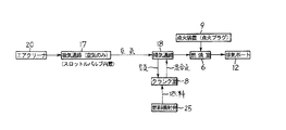
- An ignition plug 9 constituting an ignition device is fixed to the cylinder head 5, and the spark plug 9 rushes into the combustion chamber 6.
- a crankshaft 10 is rotatably supported in the crankcase 7, and the crankshaft 10 and the piston pin 4a of the piston 4 are connected by a connecting rod 11.
- crankshaft 10 When the piston 4 slides back and forth in the cylinder 3 due to combustion expansion (explosion) in the combustion chamber 6, the crankshaft 10 is rotationally driven via the connecting rod 11 and rotates to an output shaft (not shown) connected to the crankshaft 10. The driving force is output.
- An exhaust port 12 and at least one scavenging port 14 are opened on the inner wall of the cylinder 3, and these ports 12 and 14 are controlled to open and close at a predetermined timing by the reciprocating movement of the piston 4.
- the exhaust port 12 communicates with the muffler 15a via the exhaust pipe 15.
- the scavenging port 14 communicates with the crank chamber 8 via the scavenging passage 18.
- the engine 1 includes an intake passage 17 for supplying air.
- the intake passage 17 sucks only air by the negative pressure when the piston 4 operates.
- a butterfly type throttle valve 19 is arranged in the intake passage 17, and an air cleaner 20 is arranged on the upstream side of the throttle valve 19.
- the opening degree of the throttle valve 19 is adjusted by the operator operating an output operating member (throttle trigger, throttle lever, etc.) of the working machine.
- the intake passage 17 communicates with the scavenging passage 18.
- a check valve 23 for preventing backflow of air from the scavenging passage 18 is provided on the intake passage 17.
- the intake passage 17 is connected to an intake port 24 formed at the end of the scavenging passage 18 on the scavenging port 14 side. Then, the intake passage 17 guides the air purified by the air cleaner 20 to the scavenging passage 18.
- the intake passage 17 opens to only one intake port 24.
- the air purified by the air cleaner 20 passes through the check valve 23, the intake port 24, and the scavenging passage 18 in this order from the intake passage 17 in the suction stroke in which the crank chamber 8 becomes a negative pressure, and is sucked into the crank chamber 8. NS.
- air stays in the scavenging passage 18. This retained air flows into the cylinder 3 from the scavenging port 14 prior to the air-fuel mixture in the crank chamber 8 in the scavenging stroke.
- the combustion gas in the combustion chamber 6 is discharged from the exhaust port 12.
- the engine 1 includes a fuel injection valve 25 for supplying fuel into the crank chamber 8.
- the fuel mixes with air in the crank chamber 8 to form an air-fuel mixture.
- the fuel injection valve 25 is arranged below the crankcase 7.
- a fuel tank 26 and a fuel pump 27 are connected to the fuel injection valve 25.
- the fuel in the fuel tank 26 is supplied to the fuel injection valve 25 by the operation of the fuel pump 27, and the fuel injection is controlled by opening and closing the fuel injection valve 25.
- the fuel injection valve 25 is opened and closed by a control device 28 including a microcomputer.
- a detection signal of at least one sensor 29 (29a to 29g) for detecting the operating status of the engine 1 is input to the control device 28.
- the control device 28 controls the fuel supply to the crank chamber 8 by the fuel injection valve 25 based on the detection of the sensor 29.
- an intake air temperature sensor 29a that detects an intake air temperature and emits a signal
- an intake pressure sensor 29b that detects an intake pressure and emits a signal
- a signal that detects the opening degree of a throttle valve 19.
- Throttle valve opening sensor 29c that emits a signal
- crank chamber pressure sensor 29d that detects the pressure of the crank chamber 8 and emits a signal
- crank chamber temperature sensor 29e that detects the temperature of the crank chamber 8 and emits a signal
- the number of revolutions of the engine 1 examples include an engine rotation speed sensor 29f that detects and emits a signal, and a crank angle sensor 29g that detects a crank angle and emits a signal.
- the signals of these sensors 29a to 29g are input to the control device 28.
- the control device 28 emits a fuel injection signal to the fuel injection valve 25 at an appropriate timing based on various signals from the sensors 29a to 29g according to a predetermined program, and also to the spark plug 9 constituting the ignition device. And emits an ignition signal at a predetermined timing. As a result, fuel is supplied to the crank chamber 8 and the air-fuel mixture in the combustion chamber 6 is ignited.
- FIG. 2 (a) is an explanatory diagram at the time of scavenging, (b) is at the time of suction and compression, (c) is at the time of combustion expansion (explosion), and (d) is an explanatory diagram at the time of exhaust.
- the fuel injection into the crank chamber 8 may be performed in a timely manner, but as an example, it is assumed that the fuel is injected at the end of the suction stroke.
- the spark plug 9 ignites when the piston 4 reaches top dead center.
- the air-fuel mixture burns and expands (explodes) in the combustion chamber 6, and the piston 4 is pushed down to the bottom dead center, so that the crankshaft 10 rotates and power is generated.
- the lowering of the piston 4 precompresses the air-fuel mixture in the crank chamber 8.
- the check valve 23 operates, air does not flow out from the intake port 24.
- FIG. 3 shows the flow of air and fuel in the engine 1 of FIG. 1 briefly.
- the timing of the fuel supply can be easily controlled, and the air-fuel mixture suitable for the operating state of the engine 1 can be controlled. Supply becomes possible. Further, at the end of intake air, air stays in the scavenging passage 18, and the stagnant air participates in scavenging as leading air, so that the air-fuel mixture is prevented from blowing through during scavenging, and the exhaust gas component is improved. Since the intake passage 17 is configured to suck only air, the intake air can be easily controlled and the reliability of the air control can be improved. Further, since the intake passage 17 communicates with the scavenging passage 18 via the check valve 23, it can contribute to the simplification of the piston 4 and the scavenging passage 18.
- the arrangement mode and type of the fuel injection valve 25 may be, for example, as follows.
- the fuel injection valve 25 may inject fuel into the scavenging passage 18 in a direction in which the fuel does not face. In this way, fuel is less likely to be mixed into the stagnant air in the scavenging passage 18.
- the fuel injection valve 25 may be a high-pressure fuel injection valve in which at least one of an electric fuel pump and a pump operated by rotation of the crankshaft 10 enjoys fuel pressure. In this way, fuel can be injected at the target location. For example, it is possible to inject the engine 1 at a place where seizure is likely to occur.
- the fuel injection valve 25 may inject fuel at a high pressure toward a cooling-required portion in the cylinder 3 or the crank chamber 8.
- the portion requiring cooling is effectively cooled by the fuel injected from the fuel injection valve 25 at a high pressure.
- the cooling required portion include a portion where frictional heat is generated, such as a connecting portion between the connecting rod 11 and the piston pin 4a and a connecting portion between the connecting rod 11 and the crankshaft 10.
- fuel may be injected into the inner wall of the piston 4 at a high pressure.
- the fuel for a two-stroke internal combustion engine is a mixed fuel in which gasoline is mixed with lubricating oil. Therefore, when the fuel (mixed fuel) is supplied into the crank chamber 8, the lubricating oil contained in the fuel lubricates the piston 4 and the cylinder 3 promptly and quickly. As a result, seizure of the engine 1 is prevented.
- fuel may be injected using at least one of the temperature signal, the rotation speed signal, the intake pressure signal, and the opening degree signal to prevent seizure of the engine 1. For example, fuel may be injected when a high temperature is detected during high-speed operation. It is also conceivable to inject fuel to prevent seizure even when the vehicle suddenly stops during high-speed operation.
- the fuel injection valve 25 may be a high-pressure fuel injection valve capable of injecting fuel even under the maximum internal pressure of the crank chamber 8 in the operating process of the piston 4.
- the timing of fuel injection into the crank chamber can be optimized, so that the exhaust gas component can be improved, such as suppressing the mixing of gasoline with the leading air.
- the fuel injection valve 25 is located on the side where the fuel tank 26 is arranged with respect to a plane including the axis X of the cylinder 3 and the axis Y of the crankshaft 10. It may be installed. With this configuration, the positions of the fuel tank 26 and the fuel injection valve 25 are close to each other, so that the piping between the fuel tanks 26 and the fuel injection valve 25 can be shortened, which can contribute to the miniaturization and weight reduction of the work equipment. Further, by disposing the fuel injection valve 25 so that the fuel inlet 25c of the fuel injection valve 25 faces the fuel tank 26, it becomes easy to form a pipe from the fuel tank 26 to the fuel injection valve 25.
- the fuel injection valve 25a may include a fuel inlet 25c at the rear end, inject fuel toward the upper side, and the fuel tank 26 may be arranged below the crank chamber 8. In this case as well, the same effect as described above can be obtained.
- the fuel injection valve 25 one that can be electrically controlled or one that is mechanically controlled may be adopted.
- a fuel injection valve that can be opened and closed mechanically may be operatively connected to the crankshaft 10 so that the fuel injection valve is opened and closed at a predetermined timing in the operation stroke of the piston 4.
- FIG. 4A shows a state in which the piston is at top dead center
- FIG. 4B shows a state in which the piston is at bottom dead center.
- only one intake port 42 opens on the inner wall of the cylinder 41.
- An intake passage 17 communicates with the intake port 42.
- the intake port 42 is opened and closed by the piston 43.
- the piston 43 of FIG. 4 is provided with a piston groove 44 on its peripheral surface, and the intake passage 17 and the scavenging port 14 communicate with each other through the piston groove 44 at a predetermined timing.
- the crank chamber 8 becomes a negative pressure when the piston 43 operates toward the top dead center. Then, when the piston groove 44 and the scavenging port 14 overlap in the ascending process of the piston 43, the crank chamber 8 passes through the scavenging passage 18, the scavenging port 14, the piston groove 44, and the intake port 42, and the intake passage 17 Communicate with. Therefore, due to the negative pressure of the crank chamber 8, air is sucked into the crank chamber 8 through the intake passage 17, the intake port 42, the piston groove 44, the scavenging port 14, and the scavenging passage 18. Since the sucked air comes into direct contact with the peripheral surface of the piston 43, the cooling performance of the piston 43 is improved. Further, since the intake port 42 is opened and closed by the piston 43, unlike the engine 1 of FIG. 1, it is not necessary to dispose a check valve on the intake passage 17.
- FIG. 4 a modified example of FIG. 4 will be described with reference to FIG.
- components that are the same as or equivalent to the example of FIG. 4 will be designated by the same reference numerals as those in FIG. 4, and duplicate description will be omitted.
- a hole 52 communicating with the crank chamber 8 is provided in the piston groove 44 of the piston 51. Then, since air also flows from the intake port 42 to the crank chamber 8 through the hole 52, the amount of air supplied to the crank chamber 8 can be increased.
- FIG. 4 a modified example of FIG. 4 will be described with reference to FIG.
- components that are the same as or equivalent to the example of FIG. 4 will be designated by the same reference numerals as those in FIG. 4, and duplicate description will be omitted.
- a communication portion 61 for communicating the intake passage 17 and the crank chamber 8 is provided between the lower end of the piston 43 and the lower end of the intake port 42.
- air also flows from the intake port 42 into the crank chamber 8 through the communication portion 61, so that the amount of air supplied to the crank chamber 8 can be increased.
- a downward expansion portion 61a is provided at the lower end of the intake port 42, and the communication portion 61 is formed by the expansion portion 61a. good. In this case, air flows from the intake port 42 into the crank chamber 8 through the expansion portion 61a.
- a notch 61b may be provided at the lower end of the piston 62, and the communication portion 61 may be formed by the notch 61b. In this case, air flows from the intake port 42 into the crank chamber 8 through the notch 61b.
- FIG. 7 a modified example of FIG. 4 will be described with reference to FIG. 7.
- components that are the same as or equivalent to the example of FIG. 4 will be designated by the same reference numerals as those in FIG. 4, and duplicate description will be omitted.
- the scavenging passage 18 has a branch passage 71 communicating with the piston groove 44 at a position closer to the crank chamber 8 than the scavenging port 14.
- the branch passage 71 since the branch passage 71 is located below the scavenging port 14, the communication time between the piston groove 44 and the branch passage 71 due to the operation of the piston 43 can be lengthened, and the intake amount can be increased to improve the output. can.
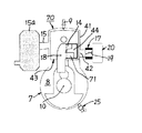
- FIGS. 8 and 9 are embodiments based on the modification of the engine 40 of FIG. 4, which is a modification of FIG. Therefore, components that are the same as or equivalent to the examples of FIGS. 1 and 4 may be designated by the same reference numerals and duplicate description may be omitted.
- the engine 80 of FIGS. 8 and 9 also has a cylinder 41 that defines the combustion chamber 6 and has an exhaust port 12, an ignition device (ignition plug 9) that ignites the air-fuel mixture of the combustion chamber 6, and the combustion chamber 6.
- a piston 43 that reciprocates in the cylinder 41 due to combustion expansion, a crank chamber 8 that communicates with the inside of the cylinder 41, a crank shaft 10 that is arranged in the crank chamber 8 and is operatively connected to the piston 43, and a crank.
- a fuel injection valve 25 that injects fuel into the chamber 8, an intake passage 17 that supplies only air sucked by the negative pressure when the piston 43 operates, and a scavenging passage 18 that communicates the crank chamber 8 and the combustion chamber 6. And. Then, the air passing through the intake passage 17 is introduced into the scavenging passage 18, and the air staying in the scavenging passage 18 in the latter half of the intake stroke is involved in the scavenging.
- a pair of scavenging passages 18 are arranged in the engine 80.
- the intake passage 17 branches into two branch paths 17a and 17b, and the branch paths 17a and 17b communicate with each of the pair of intake ports 42 and 42 arranged in the cylinder 41.
- the intake ports 42, 42 communicate with the scavenging ports 14, 14 at predetermined timings via the two piston grooves 44, 44 arranged on the peripheral surface of the piston 43, respectively.
- the booster passage 81 communicating the crank chamber 8 and the combustion chamber 6 is arranged separately from the pair of scavenging passages 18 and 18. .
- the booster passage 81 communicates with the combustion chamber 6 via the top dead center side booster port 81a formed in the cylinder 41, and communicates with the crank chamber 8 via the bottom dead center side booster port 81b formed in the crankcase 7. do.
- the booster passage 81 is for allowing the fuel in the crank chamber 8 to flow into the combustion chamber 6 during the light load operation of the engine 80 to realize stratified combustion. That is, during the light load operation of the engine 80, the fuel in the crank chamber 8 flows into the combustion chamber 6 through the booster passage 81 by the operation of the piston 43. At the same time, the air in the crank chamber 8 flows into the combustion chamber 6 through the scavenging passages 18 and 18. In this way, the air and the air-fuel mixture are separately introduced into the combustion chamber 6, and stratified combustion is performed.
- At least the fuel supply timing by the fuel injection valve 25 is controlled by the control device 28, so that homogeneous combustion is performed during the full load operation shown in FIGS. 8A and 8B.
- fuel flows into the combustion chamber 6 through the booster passage 81 to perform stratified combustion.
- the thermal efficiency during light load operation as well as during full load operation is improved.
- the fuel supply timing by the fuel injection valve 25 is controlled by the control device 28 so as to be different between the full load operation and the light load operation of the engine 80. That is, during full load operation of the engine 80, fuel is supplied from the fuel injection valve 25 at the timing when the piston 43 is located near the top dead center side, as shown in FIG. 8B. In this configuration, the air-fuel mixture generated by mixing in the crank chamber 8 is introduced into the combustion chamber 6 from the lower end side of the scavenging passages 18 and 18. As a result, the homogeneity of the air-fuel mixture in the crank chamber 8 is improved during full-load operation, which is suitable for homogeneous combustion.
- the timing at which the piston 43 is located on the bottom dead center side more preferably the timing immediately before the piston 43 reaches the vicinity of the bottom dead center.
- fuel is supplied from the fuel injection valve 25.
- the fuel supplied from the fuel injection valve 25 tends to flow into the combustion chamber 6 through the booster passage 81 before being mixed with the air in the crank chamber 8.
- the air filled in the crank chamber 8 is introduced from the scavenging passages 18 and 18 to generate an air layer and an air-fuel mixture layer in the combustion chamber 6, and stratified combustion is realized.
- the fuel injection mode by the fuel injection valve 25 is also controlled by the control device 28 so as to be different between the full load operation and the light load operation of the engine 80. That is, during full-load operation of the engine 80, as shown in FIG. 8A, it is preferable that fuel is vigorously injected radially from the fuel injection valve 25. As a result, the fuel is likely to be scattered throughout the crank chamber 8, so that the fuel and air are likely to be uniformly mixed in the entire crank chamber 8.
- the fuel is supplied from the fuel injection valve 25 so that the fuel is located near the booster port 81b on the bottom dead center side.
- a fuel supply configuration 82 that positions the fuel supplied from the fuel injection valve 25 in the vicinity of the bottom dead center side booster port 81b during light load operation of the engine 80 is provided. It is equipped. Due to this fuel supply configuration 82, fuel easily flows into the combustion chamber 6 through the booster passage 81 during light load operation of the engine 80. Therefore, it is suitable for stratified combustion during light load operation.
- the combustion supply configuration 82 has a first configuration 82a in which the fuel injection valve 25 is arranged in the vicinity of the bottom dead center side booster port 81b.
- the second configuration 82b in which the fuel is injected from the fuel injection valve at an injection pressure that allows the fuel to stay in the vicinity of the bottom dead center side booster port 81b, can be provided together.
- the injection pressure of the fuel injection valve 25 is controlled by the control device 28.
- a fuel injection valve 25 is arranged so that fuel is injected toward the bottom dead center side booster port 81b.
- One configuration 82c and a second configuration 82d in which fuel is injected from the fuel injection valve 25 at an injection pressure at which fuel can reach the bottom dead center side booster port 81b may be provided together. Also in this case, the injection pressure of the fuel injection valve 25 is controlled by the control device 28.
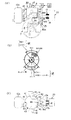
- two scavenging ports are provided on the inner peripheral surface of the cylinder.
- An exhaust port is provided on one arc surface side of the inner peripheral surface of the cylinder between these two scavenging ports.
- the top dead center side booster port is arranged on the other arc surface side of the inner peripheral surface of the cylinder between the two scavenging ports.
- the opening position of the booster port on the top dead center side in the axial direction of the cylinder may be a position lower than the exhaust port (bottom dead center side), and may be a position substantially the same height as the scavenging port.
- the configuration in which the booster passage is provided and the fuel supply timing from the fuel injection valve is controlled to perform stratified combustion during light load operation is not limited to the embodiment shown in FIGS. 8 and 9, and is not limited to the embodiment shown in FIGS. Of course, it can also be applied to embodiments.
Abstract
This two-cycle internal combustion engine comprises: a fuel injection valve 25 that supplies fuel into a crank chamber 8; an intake passage 17 that intakes only air, said intake being due to the negative pressure when a piston 4 operates; and a scavenge passage 18 that communicates the crank chamber 8 and a combustion chamber 6. The air that passes through the intake passage 17 is introduced into the scavenge passage 18, and when the intake is completed, the air retained in the scavenge passage 18 participates in the scavenging.
Description
本発明は、2サイクル内燃エンジンと、2サイクル内燃エンジンを動力源とするエンジン作業機に関するものである。
The present invention relates to a two-stroke internal combustion engine and an engine working machine powered by a two-cycle internal combustion engine.
刈払機、チェーンソー、パワーブロアなどの携帯式作業機には、動力源として2サイクル内燃エンジンが多用されている。2サイクル内燃エンジンにおいては、気化器で燃料と空気により混合気が生成され、この混合気がクランク室へと吸入される。2サイクル内燃エンジンは、クランク室と燃焼室とを連通する掃気通路を有する。シリンダ内をピストンが作動することにより、クランク室で予圧縮された混合気が掃気通路を通じて燃焼室に導入され、この混合気によって掃気が行われる。
Two-stroke internal combustion engines are often used as a power source for portable work machines such as brush cutters, chainsaws, and power blowers. In a two-stroke internal combustion engine, a carburetor produces an air-fuel mixture with fuel and air, and this air-fuel mixture is sucked into the crank chamber. The two-stroke internal combustion engine has a scavenging passage that connects the crank chamber and the combustion chamber. When the piston operates in the cylinder, the air-fuel mixture precompressed in the crank chamber is introduced into the combustion chamber through the scavenging passage, and the scavenging is performed by this air-fuel mixture.
2サイクル内燃エンジンは、周知の「混合気(新気)の吹き抜け」の問題を有する。すなわち、燃焼室に導入される掃気用の混合気がそのままシリンダの排気口から排出されてしまうことである。混合気の吹き抜けは燃料の無駄使いであり、大気汚染の原因にもなる。
Two-stroke internal combustion engines have the well-known problem of "air-fuel mixture (fresh air) atrium". That is, the scavenging air-fuel mixture introduced into the combustion chamber is discharged as it is from the exhaust port of the cylinder. The atrium of the air-fuel mixture is a waste of fuel and causes air pollution.
この問題を解消するため、シリンダに導入する気体を、空気、混合気の順となるように構成した、いわゆる「層状掃気式2サイクルエンジン」が知られている(再表98/057053)。この技術では、空気供給用吸気通路と混合気供給用吸気通路とをそれぞれ備え、シリンダ内を往復動するピストンの動作によって、掃気通路の上部に空気を、クランクケースに混合気を充填する。これによって掃気通路の上部に滞留した空気を掃気に関与させ、所謂、先導空気により吹き抜けを軽減する。
In order to solve this problem, a so-called "layered scavenging two-stroke engine" in which the gas to be introduced into the cylinder is configured in the order of air and air-fuel mixture is known (re-table 98/057053). In this technique, an intake passage for air supply and an intake passage for air-fuel mixture supply are provided, respectively, and air is filled in the upper part of the scavenging passage and the air-fuel mixture is filled in the crankcase by the operation of a piston that reciprocates in the cylinder. As a result, the air accumulated in the upper part of the scavenging passage is involved in the scavenging, and the so-called leading air reduces the atrium.
この構成においては、先導空気と混合気の双方の供給量とタイミングが、燃焼室内に発生する負圧や掃気通路の上部に滞留した空気の量によって従属的に定まってしまい、精密なコントロールができない。一案として、先導空気と混合気の供給配分を規定するために、それぞれの吸気通路の断面積を適宜に設定し空気と混合気の吸気割合を調整する等の対策案も採用できる。しかし、このような対策であっても、広い回転数領域の全ての運転領域で最適な供給配分を実現するような精密な制御はできない。また、エンジンへの損傷を回避するためには、全ての回転数領域で運転の確実性を保つことのできる、混合気供給量を優先した(濃い目の)設定にならざるを得なかった。
In this configuration, the supply amount and timing of both the leading air and the air-fuel mixture are dependently determined by the negative pressure generated in the combustion chamber and the amount of air accumulated in the upper part of the scavenging passage, and precise control cannot be performed. .. As one idea, in order to regulate the supply distribution of the leading air and the air-fuel mixture, it is possible to adopt a countermeasure such as adjusting the intake ratio of the air and the air-fuel mixture by appropriately setting the cross-sectional area of each intake passage. However, even with such measures, precise control that realizes the optimum supply distribution in all operating regions in a wide rotation speed region cannot be performed. In addition, in order to avoid damage to the engine, it was necessary to give priority to the amount of air-fuel mixture supply (darker) so that the reliability of operation could be maintained in all the rotation speed ranges.
また、2サイクル内燃エンジンは携帯型作業機に広く用いられるが、その特性上、高回転、高負荷域だけでなく、低回転から高回転への加減速や中間的な回転数、軽負荷領域も頻繁に使用される。このような2サイクル内燃エンジンにおいても、エンジンの運転状態に最も適する先導空気および混合気を燃焼室へ供給することが望ましい。より詳細には、上述のようなさまざまな運転状態において、先導空気量と混合気量のそれぞれを正確にコントロールすること、エンジンの各運転領域に要求される混合気の供給量に依存せずに、充分な先導空気供給量を設定すること、エンジンのコンパクト性を維持すること、等が求められる。
In addition, two-stroke internal combustion engines are widely used in portable work machines, but due to their characteristics, they are not only in the high rpm and high load range, but also in the acceleration / deceleration from low rpm to high rpm, intermediate rpm, and light load range. Is also frequently used. Even in such a two-stroke internal combustion engine, it is desirable to supply the leading air and the air-fuel mixture that are most suitable for the operating state of the engine to the combustion chamber. More specifically, in various operating conditions as described above, it is possible to accurately control each of the leading air amount and the air-fuel mixture amount, without depending on the air-fuel mixture supply amount required for each operating region of the engine. , Setting a sufficient amount of leading air supply, maintaining the compactness of the engine, etc. are required.
本発明は、前記のような事情に鑑みてなされたもので、掃気時の混合気の吹き抜けを防止可能であり、且つ、エンジンの運転状態に適した混合気を燃焼室に供給可能な2サイクル内燃エンジンを提供しようとするものである。
The present invention has been made in view of the above circumstances, and has two cycles in which it is possible to prevent the air-fuel mixture from blowing through during scavenging and to supply the air-fuel mixture suitable for the operating state of the engine to the combustion chamber. It seeks to provide an internal combustion engine.
本発明はまた、前記2サイクル内燃エンジンを動力源とするエンジン作業機を提供しようとするものである。
The present invention also provides an engine working machine powered by the two-stroke internal combustion engine.
前記課題を解決するため、本発明に係る2サイクル内燃エンジンは、燃焼室を画成し且つ排気口を有するシリンダと、前記燃焼室の混合気に点火する点火装置と、前記燃焼室での燃焼膨張により前記シリンダ内を往復動するピストンと、前記シリンダの内部と連通するクランク室と、該クランク室内に配設されて前記ピストンと作動上連結されるクランクシャフトと、前記クランク室内に燃料を噴射する燃料噴射弁と、前記ピストンの作動時の負圧によって空気のみを吸入する吸気通路と、前記クランク室と前記燃焼室とを連通する掃気通路と、を備え、前記吸気通路を通過する空気が前記掃気通路に導入され、吸気の終了時に前記掃気通路内に滞留する空気が掃気に関与することを特徴とする。
In order to solve the above problems, the two-stroke internal combustion engine according to the present invention includes a cylinder that defines a combustion chamber and has an exhaust port, an ignition device that ignites an air-fuel mixture in the combustion chamber, and combustion in the combustion chamber. A piston that reciprocates in the cylinder due to expansion, a crank chamber that communicates with the inside of the cylinder, a crank shaft that is arranged in the crank chamber and is operatively connected to the piston, and fuel is injected into the crank chamber. A fuel injection valve is provided, an intake passage that sucks only air by a negative pressure when the piston is operated, and a scavenging passage that communicates the crank chamber and the combustion chamber, and the air passing through the intake passage is provided. It is characterized in that air introduced into the scavenging passage and staying in the scavenging passage at the end of intake is involved in scavenging.
本発明によれば、燃料噴射弁によってクランク室内に燃料が噴射される。また、吸気通路を通過する空気が掃気通路に導入される。掃気通路に導入される空気はクランク室に吸入される。吸気の終了時には掃気通路に空気が滞留する。掃気通路を介してクランク室内に導入された空気は燃料と混合して混合気となる。クランク室内の混合気は、ピストンの作動によって掃気通路を通って燃焼室へと導入される。燃焼室の混合気は、ピストンによって圧縮され、点火装置によって点火されて燃焼膨張する。この燃焼膨張でピストンが押し戻される過程で、掃気と排気が行われる。すなわち、掃気通路内に滞留する空気が、燃焼室へと圧送されて掃気に関与し、この掃気により、排気口から燃焼ガスが排出される。
According to the present invention, fuel is injected into the crank chamber by a fuel injection valve. In addition, air passing through the intake passage is introduced into the scavenging passage. The air introduced into the scavenging passage is sucked into the crank chamber. At the end of intake, air stays in the scavenging passage. The air introduced into the crank chamber through the scavenging passage mixes with the fuel to form an air-fuel mixture. The air-fuel mixture in the crank chamber is introduced into the combustion chamber through the scavenging passage by the operation of the piston. The air-fuel mixture in the combustion chamber is compressed by a piston and ignited by an igniter to burn and expand. Scavenging and exhaust are performed in the process of pushing back the piston by this combustion expansion. That is, the air staying in the scavenging passage is pumped to the combustion chamber and participates in the scavenging, and the combustion gas is discharged from the exhaust port by this scavenging.
以上のように、本発明によれば、燃料噴射弁によってクランク室内に燃料が供給されるので、燃料供給のタイミングの制御が容易となり、エンジンの運転状態に適した混合気の供給が可能となる。また、吸気通路は空気のみを吸入し、且つ、吸気通路を通過する空気は掃気通路に導入されるので、吸気通路を簡易に形成することができる。吸気通路が空気のみを吸入することで、吸入空気の制御が容易となるほか、空気制御の信頼性の向上にも貢献できる。吸気の終了時には掃気通路に空気が滞留し、この空気が掃気に関与するので、掃気時の混合気の吹き抜けが防止され、排気ガスの成分が改善される。
As described above, according to the present invention, since fuel is supplied to the crank chamber by the fuel injection valve, it becomes easy to control the timing of fuel supply, and it is possible to supply an air-fuel mixture suitable for the operating state of the engine. .. Further, since the intake passage sucks only air and the air passing through the intake passage is introduced into the scavenging passage, the intake passage can be easily formed. By sucking only air through the intake passage, it becomes easy to control the intake air and it can contribute to the improvement of the reliability of the air control. At the end of intake, air stays in the scavenging passage, and this air is involved in scavenging, so that the air-fuel mixture is prevented from blowing through during scavenging, and the exhaust gas component is improved.
また、本発明によれば、吸気側には空気通路のみを配置すればよいため、従来の層状掃気式エンジンにおいて設けられていた混合気供給用の吸気通路及び吸気ポートが不要となることから、シリンダ、マニーホールド等も簡易に形成することができる。この構成により、空気制御弁を簡素化でき吸入空気量制御の容易化・信頼性の向上にも貢献できる。シリンダの構成についてより詳細には、従来、空気ポート及び混合気ポートを上下ないし周方向に並べて配置する必要があったところ、本発明では混合気供給用のポートが不要になることから、シリンダにおけるポート開口の設計自由度が格段に向上する。
Further, according to the present invention, since only the air passage needs to be arranged on the intake side, the intake passage and the intake port for supplying the air-fuel mixture, which are provided in the conventional layered scavenging engine, are not required. Cylinders, manifolds, etc. can also be easily formed. With this configuration, the air control valve can be simplified, and the intake air amount control can be facilitated and the reliability can be improved. More specifically about the configuration of the cylinder, conventionally, it has been necessary to arrange the air port and the air-fuel mixture port side by side in the vertical or circumferential direction. However, in the present invention, the port for supplying the air-fuel mixture becomes unnecessary. The degree of freedom in designing the port opening is greatly improved.
実施の一形態として、前記ピストンは、ピストン溝を備え、前記吸気ポートと前記掃気通路は前記ピストン溝を介して連通される態様としてもよい。この場合、ピストンによって吸気ポートが開閉されるので、逆止弁を配設する必要がない。
As one embodiment, the piston may include a piston groove, and the intake port and the scavenging passage may communicate with each other through the piston groove. In this case, since the intake port is opened and closed by the piston, it is not necessary to dispose of a check valve.
実施の一形態として、前記ピストン溝に、前記クランク室と連通する孔が設けられる態様としてもよい。この場合、孔を通して吸気ポートからクランク室へも空気が流入するので、クランク室への給気量を増大させることができる。
As one embodiment, the piston groove may be provided with a hole communicating with the crank chamber. In this case, since air also flows from the intake port to the crank chamber through the hole, the amount of air supplied to the crank chamber can be increased.
実施の一形態として、前記ピストンの下端と前記吸気ポートの下端との間に、前記吸気通路と前記クランク室とを連通させる連通部を備える態様としてもよい。この場合、連通部を通して吸気ポートからクランク室へも空気が流入するので、クランク室への給気量を増大させることができる。
As one embodiment, a communication portion for communicating the intake passage and the crank chamber may be provided between the lower end of the piston and the lower end of the intake port. In this case, since air also flows into the crank chamber from the intake port through the communication portion, the amount of air supplied to the crank chamber can be increased.
実施の一形態として、前記ピストンの下端に切欠きを備え、該切欠きによって前記連通部が形成される態様としてもよい。この場合、切欠きを通して吸気ポートからクランク室へ空気が流入する。
As one embodiment, a notch may be provided at the lower end of the piston, and the communication portion may be formed by the notch. In this case, air flows from the intake port into the crank chamber through the notch.
実施の一形態として、前記吸気ポートの下端に下方への拡大部を備え、該拡大部によって前記連通部が形成される態様としてもよい。この場合、拡大部を通して吸気ポートからクランク室へ空気が流入する。
As one embodiment, a downward expanding portion may be provided at the lower end of the intake port, and the communicating portion may be formed by the expanding portion. In this case, air flows from the intake port to the crank chamber through the enlarged portion.
実施の一形態として、前記掃気通路は、前記掃気ポートよりも前記クランク室寄りの位置に、前記ピストン溝と連通する分岐通路を有する態様としてもよい。この場合、吸気ポートから分岐通路を通してクランク室へ空気が流入するので、クランク室への給気量を増大させることができる。
As one embodiment, the scavenging passage may have a branch passage communicating with the piston groove at a position closer to the crank chamber than the scavenging port. In this case, since air flows into the crank chamber from the intake port through the branch passage, the amount of air supplied to the crank chamber can be increased.
実施の一形態として、前記燃料噴射弁は、前記掃気通路から前記クランク室への空気の流入を阻害しない方向に燃料を噴射する態様としてもよい。
As one embodiment, the fuel injection valve may inject fuel in a direction that does not obstruct the inflow of air from the scavenging passage into the crank chamber.
実施の一形態として、前記燃料噴射弁が、電動燃料ポンプと、前記クランクシャフトの回転により動作するポンプの、少なくとも一つに燃圧を享受される高圧式燃料噴射弁である態様としてもよい。このようにすれば、狙ったところに燃料を噴射できる。
As one embodiment, the fuel injection valve may be a high-pressure fuel injection valve in which at least one of an electric fuel pump and a pump operated by rotation of the crankshaft enjoys fuel pressure. In this way, fuel can be injected at the target location.
実施の一形態として、前記燃料噴射弁が、前記シリンダ内又は前記クランク室内の要冷却部位に向けて高圧で燃料を噴射する態様としてもよい。このようにすれば、燃料噴射弁から高圧で噴射される燃料により、要冷却部位が効果的に冷却される。
As one embodiment, the fuel injection valve may inject fuel at a high pressure toward a cooling-required portion in the cylinder or the crank chamber. In this way, the cooling-required portion is effectively cooled by the fuel injected at high pressure from the fuel injection valve.
実施の一形態として、前記燃料噴射弁が、前記ピストンの作動過程における前記クランク室の最高内圧下においても燃料を噴射可能な高圧式燃料噴射弁とされる態様としてもよい。このようにすれば、クランク室内への燃料噴射のタイミングが最適化できるため、掃気通路の滞留空気への燃料混合を抑止するなど排気ガスの成分を改善できる。
As one embodiment, the fuel injection valve may be a high-pressure fuel injection valve capable of injecting fuel even under the maximum internal pressure of the crank chamber in the operating process of the piston. By doing so, the timing of fuel injection into the crank chamber can be optimized, so that the components of the exhaust gas can be improved, such as suppressing fuel mixing with the stagnant air in the scavenging passage.
実施の一形態として、前記吸気通路は一か所のみの吸気ポートに開口する態様としてもよい。このようにすれば、従来の、混合気ポートおよび2か所の空気用ポートを設ける構成に比して吸気通路を簡易に形成することができ、作業機のコンパクト性に大いに寄与できる。
As one embodiment, the intake passage may be opened to only one intake port. In this way, the intake passage can be easily formed as compared with the conventional configuration in which the air-fuel mixture port and the two air ports are provided, which can greatly contribute to the compactness of the working machine.
実施の一形態として、前記クランク室と前記燃焼室とを連通するブースター通路が前記掃気通路とは別に配設され、前記燃料噴射弁による燃料供給タイミングが制御装置で制御されることにより、全負荷運転時には均質燃焼が行われる一方、軽負荷運転時には、前記ブースター通路を介して燃料が前記燃焼室に流入して成層燃焼が行われる態様としてもよい。この場合、全負荷運転時には均質燃焼が行われ、軽負荷運転時には成層燃焼が行われる。これにより、全負荷運転時に加えて軽負荷運転時の熱効率も改善される。
As one embodiment, a booster passage connecting the crank chamber and the combustion chamber is arranged separately from the scavenging passage, and the fuel supply timing by the fuel injection valve is controlled by the control device, whereby the total load is reached. While homogeneous combustion is performed during operation, fuel may flow into the combustion chamber through the booster passage to perform stratified combustion during light load operation. In this case, homogeneous combustion is performed during full load operation, and stratified combustion is performed during light load operation. As a result, the thermal efficiency during light load operation as well as during full load operation is improved.
実施の一形態として、前記クランク室と前記ブースター通路とを連通させる下死点側ブースターポートと、前記燃料噴射弁から供給される燃料を軽負荷運転時に前記下死点側ブースターポートの近傍に位置させる燃料供給構成と、を備える態様としてもよい。この場合、燃料噴射弁から供給される燃料が軽負荷運転時に下死点側ブースターポートの近傍に導入される(流入する)ので、燃料がブースター通路を介して燃焼室へと流入しやすい。一方、空気は掃気通路から燃焼室に導入されており、空気と混合気が別の通路から導入されることによって、軽負荷運転時の成層燃焼に適する。
As one embodiment, a bottom dead center side booster port that communicates the crank chamber and the booster passage and a fuel supplied from the fuel injection valve are located near the bottom dead center side booster port during light load operation. It may be an embodiment including a fuel supply configuration for causing the fuel to be supplied. In this case, since the fuel supplied from the fuel injection valve is introduced (inflows) into the vicinity of the booster port on the bottom dead center side during light load operation, the fuel easily flows into the combustion chamber through the booster passage. On the other hand, air is introduced into the combustion chamber from the scavenging passage, and the air and the air-fuel mixture are introduced from another passage, which is suitable for stratified combustion during light load operation.
実施の一形態として、前記燃料供給構成は、前記燃料噴射弁が前記下死点側ブースターポートの近傍に配置される第一構成と、前記下死点側ブースターポートの近傍に滞留可能な噴射圧で前記燃料噴射弁から燃料が噴射される第二構成と、を共に備える態様としてもよい。
As one embodiment, the fuel supply configuration includes a first configuration in which the fuel injection valve is arranged in the vicinity of the bottom dead center side booster port and an injection pressure capable of staying in the vicinity of the bottom dead center side booster port. The mode may include both a second configuration in which fuel is injected from the fuel injection valve and the above.
実施の一形態として、前記燃料供給構成は、前記下死点側ブースターポートに向けて燃料が噴射されるように前記燃料噴射弁が配置される第一構成と、前記下死点側ブースターポートに到達可能な噴射圧で前記燃料噴射弁から燃料が噴射される第二構成と、を共に備える態様としてもよい。
As one embodiment, the fuel supply configuration includes a first configuration in which the fuel injection valve is arranged so that fuel is injected toward the bottom dead center side booster port, and the bottom dead center side booster port. The mode may also include a second configuration in which fuel is injected from the fuel injection valve at a reachable injection pressure.
実施の一形態として、全負荷運転時には、前記ピストンが上死点側に位置するタイミングで前記燃料噴射弁から燃料が供給され、軽負荷運転時には、前記ピストンが下死点に到達する直前のタイミングで前記燃料噴射弁から燃料が供給される態様としてもよい。このようにすれば、全負荷運転時には、クランク室内での混合気の均質性が向上するので、均質燃焼に適する。一方、軽負荷運転時には、燃料噴射弁から供給された燃料がクランク室内に充填する空気と混ざる前に、ブースター通路を介して燃焼室へと流入する。クランク室内に充填した空気には燃料が混合されずに掃気通路から燃焼室へと導入されるので、成層燃焼に適する。
As one embodiment, fuel is supplied from the fuel injection valve at the timing when the piston is located on the top dead center side during full load operation, and at the timing immediately before the piston reaches bottom dead center during light load operation. The fuel may be supplied from the fuel injection valve. In this way, the homogeneity of the air-fuel mixture in the crank chamber is improved during full-load operation, which is suitable for homogeneous combustion. On the other hand, during light load operation, the fuel supplied from the fuel injection valve flows into the combustion chamber through the booster passage before being mixed with the air filled in the crank chamber. Since fuel is not mixed with the air filled in the crank chamber and is introduced into the combustion chamber from the scavenging passage, it is suitable for stratified combustion.
実施の一形態として、前記掃気通路と前記燃焼室とを連通させる掃気ポートが前記シリンダの内周面に一対配設され、該一対の掃気ポート間における一方の円弧面側に前記排気ポートが配設され、前記燃焼室と前記ブースター通路とを連通させる上死点側ブースターポートが、前記一対の掃気ポート間における他方の円弧面側に配設される態様としてもよい。この場合、軽負荷運転時には、ブースター通路を介して燃焼室に燃料が流入すると共に、一対の掃気ポートから燃焼室に空気が流入する。掃気通路とは別に設けられた、混合気供給のためのブースターポートから濃い混合気が燃焼室内の空気と混合することにより、点火装置の点火部付近に濃い混合気が形成される。これにより、軽負荷運転時の成層燃焼の確実性が向上する。
As one embodiment, a pair of scavenging ports that communicate the scavenging passage and the combustion chamber are arranged on the inner peripheral surface of the cylinder, and the exhaust port is arranged on one arc surface side between the pair of scavenging ports. The top dead center side booster port that is provided and communicates the combustion chamber and the booster passage may be arranged on the other arc surface side between the pair of scavenging ports. In this case, during light load operation, fuel flows into the combustion chamber through the booster passage, and air flows into the combustion chamber from the pair of scavenging ports. A rich air-fuel mixture is formed in the vicinity of the ignition portion of the ignition device by mixing the rich air-fuel mixture with the air in the combustion chamber from the booster port for supplying the air-fuel mixture provided separately from the scavenging passage. This improves the certainty of stratified combustion during light load operation.
以上説明したように、本発明によれば、2サイクル内燃エンジンの高回転、高負荷域だけでなく、低回転から高回転への加減速や中間的な回転数、軽負荷領域においても、エンジンの運転状態に最も適する先導空気および混合気を燃焼室へ供給することができる。また、燃料噴射装置の配置、タイミング制御、指向性のそれぞれを組み合わせることで先導空気量と混合気量のそれぞれを正確にコントロールすることができる。なお、シリンダには空気を吸入する空気用の空気ポートのみが開口するため、充分な先導空気供給量を設定することが可能であり、かつ、エンジンの吸気側(反排気側)の構造簡素化、コンパクト性にも寄与できる。
As described above, according to the present invention, not only in the high rotation and high load range of a two-stroke internal combustion engine, but also in the acceleration / deceleration from low rotation to high rotation, intermediate rotation speed, and light load region. Leading air and air-fuel mixture that are most suitable for the operating conditions of the above can be supplied to the combustion chamber. Further, by combining the arrangement of the fuel injection device, the timing control, and the directivity, it is possible to accurately control each of the leading air amount and the air-fuel mixture amount. Since only the air port for air that sucks air opens in the cylinder, it is possible to set a sufficient amount of leading air supply, and the structure of the intake side (anti-exhaust side) of the engine is simplified. , Can also contribute to compactness.
実施の一形態として、前記吸気通路に逆止弁を備える態様としてもよい。逆止弁を設けることにより、前回サイクルにおける燃焼室からの吹き返しが吸気通路に混入せず、次のサイクルでの空気供給量および燃料噴射量をより精密に管理できる。
As one embodiment, a check valve may be provided in the intake passage. By providing the check valve, the blowback from the combustion chamber in the previous cycle is not mixed in the intake passage, and the air supply amount and the fuel injection amount in the next cycle can be controlled more precisely.
実施の一形態として、前記2サイクル内燃エンジンを動力源として備えるエンジン作業機を提供してもよい。
As one embodiment, an engine working machine including the two-cycle internal combustion engine as a power source may be provided.
以下、添付図面を参照して、本発明の実施の形態について説明する。
Hereinafter, embodiments of the present invention will be described with reference to the accompanying drawings.
本発明に係る2サイクル内燃エンジン(以下、単に「エンジン」という。)は、主に携帯式のエンジン作業機に動力源として搭載される空冷式のものである。本発明のエンジンが用いられる作業機としては、チェーンソー、刈払機、動力カッター、ヘッジトリマー、パワーブロワ等の、手持式、肩掛式又は背負式等の携帯式作業機が挙げられる。
The two-cycle internal combustion engine (hereinafter, simply referred to as "engine") according to the present invention is an air-cooled engine mainly mounted as a power source in a portable engine work machine. Examples of the working machine in which the engine of the present invention is used include a handheld type, a shoulder-mounted type, a backpack type, and other portable working machines such as a chainsaw, a brush cutter, a power cutter, a hedge trimmer, and a power blower.
図1に示すように、本発明の実施の一形態に係るエンジン1は、シリンダブロック2と、このシリンダブロック2を構成するシリンダ3内を往復摺動するピストン4と、を備える。シリンダブロック2の一端側を構成するシリンダヘッド5とピストン4とによって燃焼室6が画成され、シリンダブロック2の他端側を構成するクランクケース7とピストン4とによってクランク室8が画成される。シリンダヘッド5には点火装置を構成する点火プラグ9が固着され、この点火プラグ9は燃焼室6に突入している。クランクケース7内にはクランクシャフト10が回動自在に支持され、このクランクシャフト10とピストン4のピストンピン4aとが連接棒11によって連結される。燃焼室6での燃焼膨張(爆発)によりピストン4がシリンダ3内を往復摺動することにより、連接棒11を介してクランクシャフト10が回転駆動され、クランクシャフト10に繋がる図示しない出力軸に回転駆動力が出力される。
As shown in FIG. 1, the engine 1 according to the embodiment of the present invention includes a cylinder block 2 and a piston 4 that reciprocates in the cylinder 3 constituting the cylinder block 2. The combustion chamber 6 is defined by the cylinder head 5 and the piston 4 which form one end side of the cylinder block 2, and the crankcase 8 is defined by the crankcase 7 and the piston 4 which form the other end side of the cylinder block 2. NS. An ignition plug 9 constituting an ignition device is fixed to the cylinder head 5, and the spark plug 9 rushes into the combustion chamber 6. A crankshaft 10 is rotatably supported in the crankcase 7, and the crankshaft 10 and the piston pin 4a of the piston 4 are connected by a connecting rod 11. When the piston 4 slides back and forth in the cylinder 3 due to combustion expansion (explosion) in the combustion chamber 6, the crankshaft 10 is rotationally driven via the connecting rod 11 and rotates to an output shaft (not shown) connected to the crankshaft 10. The driving force is output.
シリンダ3の内壁には、排気ポート12と少なくとも一つの掃気ポート14が開口しており、これらのポート12,14がピストン4の往復動によって所定のタイミングで開閉制御される。排気ポート12は排気管15を介してマフラ15aに連通する。掃気ポート14は、掃気通路18を介してクランク室8に連通する。
An exhaust port 12 and at least one scavenging port 14 are opened on the inner wall of the cylinder 3, and these ports 12 and 14 are controlled to open and close at a predetermined timing by the reciprocating movement of the piston 4. The exhaust port 12 communicates with the muffler 15a via the exhaust pipe 15. The scavenging port 14 communicates with the crank chamber 8 via the scavenging passage 18.
エンジン1は、空気供給用の吸気通路17を備える。吸気通路17は、ピストン4の作動時の負圧によって空気のみを吸入する。吸気通路17内にはバタフライ式等のスロットルバルブ19が配設され、スロットルバルブ19の上流側にはエアクリーナ20が配設される。スロットルバルブ19の開度は、作業者が作業機の出力操作部材(スロットルトリガやスロットルレバー等)を操作することで調整される。
The engine 1 includes an intake passage 17 for supplying air. The intake passage 17 sucks only air by the negative pressure when the piston 4 operates. A butterfly type throttle valve 19 is arranged in the intake passage 17, and an air cleaner 20 is arranged on the upstream side of the throttle valve 19. The opening degree of the throttle valve 19 is adjusted by the operator operating an output operating member (throttle trigger, throttle lever, etc.) of the working machine.
吸気通路17は掃気通路18に連通される。吸気通路17上には、掃気通路18からの空気の逆流を防止する逆止弁23が配設される。吸気通路17は、掃気通路18の掃気ポート14側の端部に形成される吸気ポート24に連結される。そして、吸気通路17は、エアクリーナ20で浄化された空気を掃気通路18へと導く。吸気通路17は、一か所のみの吸気ポート24に開口する。
The intake passage 17 communicates with the scavenging passage 18. A check valve 23 for preventing backflow of air from the scavenging passage 18 is provided on the intake passage 17. The intake passage 17 is connected to an intake port 24 formed at the end of the scavenging passage 18 on the scavenging port 14 side. Then, the intake passage 17 guides the air purified by the air cleaner 20 to the scavenging passage 18. The intake passage 17 opens to only one intake port 24.
エアクリーナ20で浄化された空気は、クランク室8が負圧となる吸入行程で、吸気通路17から逆止弁23、吸気ポート24、掃気通路18の順に通過して、クランク室8へと吸入される。吸入行程の終了時には、掃気通路18に空気が滞留する。この滞留空気は、掃気行程において、クランク室8内の混合気に先立って、掃気ポート14からシリンダ3内へと流入する。この空気先導式の掃気により、燃焼室6の燃焼ガスが排気ポート12から排出される。
The air purified by the air cleaner 20 passes through the check valve 23, the intake port 24, and the scavenging passage 18 in this order from the intake passage 17 in the suction stroke in which the crank chamber 8 becomes a negative pressure, and is sucked into the crank chamber 8. NS. At the end of the suction stroke, air stays in the scavenging passage 18. This retained air flows into the cylinder 3 from the scavenging port 14 prior to the air-fuel mixture in the crank chamber 8 in the scavenging stroke. By this air-led scavenging, the combustion gas in the combustion chamber 6 is discharged from the exhaust port 12.
エンジン1は、クランク室8内に燃料を供給するための燃料噴射弁25を備える。燃料は、クランク室8内で空気と混合して混合気となる。図示例では、クランクケース7の下部に燃料噴射弁25が配設されている。
The engine 1 includes a fuel injection valve 25 for supplying fuel into the crank chamber 8. The fuel mixes with air in the crank chamber 8 to form an air-fuel mixture. In the illustrated example, the fuel injection valve 25 is arranged below the crankcase 7.
燃料噴射弁25には、燃料タンク26と燃料ポンプ27が連結される。燃料ポンプ27の作動によって燃料タンク26内の燃料が燃料噴射弁25に供給され、燃料噴射弁25の開閉によって燃料の噴射が制御される。
A fuel tank 26 and a fuel pump 27 are connected to the fuel injection valve 25. The fuel in the fuel tank 26 is supplied to the fuel injection valve 25 by the operation of the fuel pump 27, and the fuel injection is controlled by opening and closing the fuel injection valve 25.
燃料噴射弁25は、マイクロコンピュータを含む制御装置28によって開閉制御される。制御装置28には、エンジン1の運転状況を検知する少なくとも一つのセンサ29(29a~29g)の検知信号が入力される。制御装置28は、センサ29の検知に基づいて、燃料噴射弁25によるクランク室8への燃料供給を制御する。
The fuel injection valve 25 is opened and closed by a control device 28 including a microcomputer. A detection signal of at least one sensor 29 (29a to 29g) for detecting the operating status of the engine 1 is input to the control device 28. The control device 28 controls the fuel supply to the crank chamber 8 by the fuel injection valve 25 based on the detection of the sensor 29.
少なくとも一つのセンサ29を例示すると、例えば、吸気温度を検知して信号を発する吸気温度センサ29a、吸気圧を検知して信号を発する吸気圧センサ29b、スロットルバルブ19の開度を検知して信号を発するスロットルバルブ開度センサ29c、クランク室8の圧力を検知して信号を発するクランク室圧力センサ29d、クランク室8の温度を検知して信号を発するクランク室温度センサ29e、エンジン1の回転数を検知して信号を発するエンジン回転数センサ29f、クランク角を検知して信号を発するクランク角センサ29gが挙げられる。これらのセンサ29a~29gの信号は制御装置28に入力される。
To exemplify at least one sensor 29, for example, an intake air temperature sensor 29a that detects an intake air temperature and emits a signal, an intake pressure sensor 29b that detects an intake pressure and emits a signal, and a signal that detects the opening degree of a throttle valve 19. Throttle valve opening sensor 29c that emits a signal, crank chamber pressure sensor 29d that detects the pressure of the crank chamber 8 and emits a signal, crank chamber temperature sensor 29e that detects the temperature of the crank chamber 8 and emits a signal, and the number of revolutions of the engine 1. Examples include an engine rotation speed sensor 29f that detects and emits a signal, and a crank angle sensor 29g that detects a crank angle and emits a signal. The signals of these sensors 29a to 29g are input to the control device 28.
制御装置28は、センサ29a~29gからの種々の信号に基づき、所定のプログラムにしたがって、燃料噴射弁25へと適宜のタイミングで燃料噴射信号を発し、また、点火装置を構成する点火プラグ9へと所定のタイミングで点火信号を発する。これにより、クランク室8への燃料供給と、燃焼室6の混合気への点火が行われる。
The control device 28 emits a fuel injection signal to the fuel injection valve 25 at an appropriate timing based on various signals from the sensors 29a to 29g according to a predetermined program, and also to the spark plug 9 constituting the ignition device. And emits an ignition signal at a predetermined timing. As a result, fuel is supplied to the crank chamber 8 and the air-fuel mixture in the combustion chamber 6 is ignited.
次に、図2を参照して、図1のエンジン1の動作について説明する。図2において、(a)は掃気時、(b)は吸入及び圧縮時、(c)は燃焼膨張(爆発)時、(d)は排気時の説明図である。なお、クランク室8への燃料噴射は適時に行われればよいが、一例として、吸入行程の終盤に行われるものとする。
Next, the operation of the engine 1 of FIG. 1 will be described with reference to FIG. In FIG. 2, (a) is an explanatory diagram at the time of scavenging, (b) is at the time of suction and compression, (c) is at the time of combustion expansion (explosion), and (d) is an explanatory diagram at the time of exhaust. The fuel injection into the crank chamber 8 may be performed in a timely manner, but as an example, it is assumed that the fuel is injected at the end of the suction stroke.
図2(a)、(b)を参照して、ピストン4が下死点から上昇する過程でピストン4により掃気ポート14が閉じると、ピストン4の上昇によりクランク室8内が負圧になる。これにより、吸気通路17から吸気ポート24と掃気通路18とを通ってクランク室8へと空気が吸入される。一例として、吸入行程の終盤で燃焼噴射弁25から燃料が噴射される。燃焼室6では、ピストン4が上死点に達するまで混合気の圧縮が行われる。ピストン4が上死点に達すると、クランク室8への空気の吸入が終了する。この時点で、クランク室8内には燃料と空気が混合した混合気が充満し、掃気通路18内には空気が滞留する。
With reference to FIGS. 2 (a) and 2 (b), when the scavenging port 14 is closed by the piston 4 in the process of the piston 4 rising from the bottom dead center, the inside of the crank chamber 8 becomes negative pressure due to the rise of the piston 4. As a result, air is sucked from the intake passage 17 into the crank chamber 8 through the intake port 24 and the scavenging passage 18. As an example, fuel is injected from the combustion injection valve 25 at the end of the suction stroke. In the combustion chamber 6, the air-fuel mixture is compressed until the piston 4 reaches top dead center. When the piston 4 reaches top dead center, the suction of air into the crank chamber 8 ends. At this point, the crank chamber 8 is filled with a mixture of fuel and air, and the air stays in the scavenging passage 18.
図2(c)を参照して、ピストン4が上死点に達した時に点火プラグ9による点火が行われる。これにより燃焼室6で混合気が燃焼膨張(爆発)し、ピストン4が下死点へと押し下げられることで、クランクシャフト10が回転して動力が発生する。ピストン4の下降により、クランク室8内の混合気が予圧縮される。このとき、逆止弁23が作用するので、吸気ポート24から空気が流出することはない。
With reference to FIG. 2C, the spark plug 9 ignites when the piston 4 reaches top dead center. As a result, the air-fuel mixture burns and expands (explodes) in the combustion chamber 6, and the piston 4 is pushed down to the bottom dead center, so that the crankshaft 10 rotates and power is generated. The lowering of the piston 4 precompresses the air-fuel mixture in the crank chamber 8. At this time, since the check valve 23 operates, air does not flow out from the intake port 24.
図2(d)を参照して、ピストン4の下降により排気ポート12が開くと、燃焼ガスが排気管15へと流出する。続いて、図2(a)に示すように掃気ポート14が開き、予圧縮されたクランク室8内の混合気が掃気通路18を通って燃焼室6へと送り込まれる。このとき、クランク室8内の混合気に先立って、掃気通路18内に滞留していた空気が先導エアとして燃焼室6へと流入し、排気ポート12へと燃焼ガスを追い出す。このため、掃気時における混合気の吹き抜けが低減される。ピストン4は、クランクシャフト10の回転により再び上死点へ向けて移動し、以後、同様の作用が繰り返される。
With reference to FIG. 2D, when the exhaust port 12 is opened by the lowering of the piston 4, the combustion gas flows out to the exhaust pipe 15. Subsequently, as shown in FIG. 2A, the scavenging port 14 is opened, and the air-fuel mixture in the precompressed crank chamber 8 is sent to the combustion chamber 6 through the scavenging passage 18. At this time, prior to the air-fuel mixture in the crank chamber 8, the air staying in the scavenging passage 18 flows into the combustion chamber 6 as leading air, and the combustion gas is expelled to the exhaust port 12. Therefore, the atrium of the air-fuel mixture during scavenging is reduced. The piston 4 moves toward the top dead center again due to the rotation of the crankshaft 10, and the same operation is repeated thereafter.
なお、図1のエンジン1における空気と燃料の流れを簡潔に示すと、図3のブロック図のようになる。
The block diagram of FIG. 3 shows the flow of air and fuel in the engine 1 of FIG. 1 briefly.
本実施の一形態のエンジン1によれば、燃料噴射弁25によってクランク室8内に燃料が供給されるので、燃料供給のタイミングの制御が容易となり、エンジン1の運転状態に適した混合気の供給が可能となる。また、吸気の終了時には掃気通路18に空気が滞留し、この滞留空気が先導エアとして掃気に関与するので、掃気時の混合気の吹き抜けが防止され、排気ガスの成分が改善される。吸気通路17が空気のみを吸入するように構成されていることで、吸入空気の制御が容易となるほか、空気制御の信頼性の向上にも貢献できる。また、吸気通路17が逆止弁23を介して掃気通路18に連通するので、ピストン4や掃気通路18の簡素化に貢献できる。
According to the engine 1 of the present embodiment, since the fuel is supplied into the crank chamber 8 by the fuel injection valve 25, the timing of the fuel supply can be easily controlled, and the air-fuel mixture suitable for the operating state of the engine 1 can be controlled. Supply becomes possible. Further, at the end of intake air, air stays in the scavenging passage 18, and the stagnant air participates in scavenging as leading air, so that the air-fuel mixture is prevented from blowing through during scavenging, and the exhaust gas component is improved. Since the intake passage 17 is configured to suck only air, the intake air can be easily controlled and the reliability of the air control can be improved. Further, since the intake passage 17 communicates with the scavenging passage 18 via the check valve 23, it can contribute to the simplification of the piston 4 and the scavenging passage 18.
なお、燃料噴射弁25の配設態様や種類は、例えば次のようにしてもよい。
The arrangement mode and type of the fuel injection valve 25 may be, for example, as follows.
好適な実施の一形態として、燃料噴射弁25は、掃気通路18へ燃料が向かわない方向に向けて燃料を噴射する態様としてもよい。このようにすれば、掃気通路18の滞留空気に燃料が混入しにくい。
As a preferred embodiment, the fuel injection valve 25 may inject fuel into the scavenging passage 18 in a direction in which the fuel does not face. In this way, fuel is less likely to be mixed into the stagnant air in the scavenging passage 18.
好適な実施の一形態として、燃料噴射弁25は、電動燃料ポンプと、クランクシャフト10の回転により動作するポンプの、少なくとも一つに燃圧を享受される高圧式燃料噴射弁としてもよい。このようにすれば、狙ったところに燃料を噴射できる。例えば、エンジン1の焼き付きが起こりやすい場所へ狙って噴射することも可能である。
As a preferred embodiment, the fuel injection valve 25 may be a high-pressure fuel injection valve in which at least one of an electric fuel pump and a pump operated by rotation of the crankshaft 10 enjoys fuel pressure. In this way, fuel can be injected at the target location. For example, it is possible to inject the engine 1 at a place where seizure is likely to occur.
好適な実施の一形態として、燃料噴射弁25は、シリンダ3内又はクランク室8内の要冷却部位に向けて高圧で燃料を噴射する態様としてもよい。このようにすれば、燃料噴射弁25から高圧で噴射される燃料により、要冷却部位が効果的に冷却される。要冷却部位として、例えば、連接棒11とピストンピン4aとの連結部や、連接棒11とクランクシャフト10との連結部等の、摩擦熱の発生部位が挙げられる。また、ピストン4を冷却するために、ピストン4の内壁に高圧で燃料を噴射してもよい。
As a preferred embodiment, the fuel injection valve 25 may inject fuel at a high pressure toward a cooling-required portion in the cylinder 3 or the crank chamber 8. In this way, the portion requiring cooling is effectively cooled by the fuel injected from the fuel injection valve 25 at a high pressure. Examples of the cooling required portion include a portion where frictional heat is generated, such as a connecting portion between the connecting rod 11 and the piston pin 4a and a connecting portion between the connecting rod 11 and the crankshaft 10. Further, in order to cool the piston 4, fuel may be injected into the inner wall of the piston 4 at a high pressure.
2サイクル内燃エンジンの燃料は、ガソリンに潤滑用オイルを混合した混合燃料である。このため、クランク室8内に燃料(混合燃料)が供給されると、燃料に含まれる潤滑用オイルにより、ピストン4とシリンダ3との潤滑が即応的且つ迅速に行われる。これによって、エンジン1の焼き付きが防止される。この場合に、温度信号、回転数信号、吸気圧信号、及び開度信号の少なくとも一つを利用して燃料を噴射してエンジン1の焼き付きを防止してもよい。例えば、高速運転時に高温を検知した際に燃料を噴射すればよい。また、高速運転時に急停止する際にも燃料を噴射して焼き付きを防止することも考えられる。
The fuel for a two-stroke internal combustion engine is a mixed fuel in which gasoline is mixed with lubricating oil. Therefore, when the fuel (mixed fuel) is supplied into the crank chamber 8, the lubricating oil contained in the fuel lubricates the piston 4 and the cylinder 3 promptly and quickly. As a result, seizure of the engine 1 is prevented. In this case, fuel may be injected using at least one of the temperature signal, the rotation speed signal, the intake pressure signal, and the opening degree signal to prevent seizure of the engine 1. For example, fuel may be injected when a high temperature is detected during high-speed operation. It is also conceivable to inject fuel to prevent seizure even when the vehicle suddenly stops during high-speed operation.
好適な実施の一形態として、燃料噴射弁25は、ピストン4の作動過程におけるクランク室8の最高内圧下においても燃料を噴射可能な高圧式燃料噴射弁としてもよい。このようにすれば、クランク室内への燃料噴射のタイミングが最適化できるため、先導エアへのガソリン混合を抑止するなど排気ガスの成分を改善できる。
As a preferred embodiment, the fuel injection valve 25 may be a high-pressure fuel injection valve capable of injecting fuel even under the maximum internal pressure of the crank chamber 8 in the operating process of the piston 4. By doing so, the timing of fuel injection into the crank chamber can be optimized, so that the exhaust gas component can be improved, such as suppressing the mixing of gasoline with the leading air.
好適な実施の一形態として、図1に示すように、燃料噴射弁25は、シリンダ3の軸線Xとクランクシャフト10の軸線Yとを含む平面に対して、燃料タンク26が配置される側に設置されてもよい。この構成により、燃料タンク26と燃料噴射弁25の位置が近くなるので、相互間の配管が短くて済み、作業機の小型化、軽量化に貢献できる。また、燃料噴射弁25の燃料入口25cが燃料タンク26へ向くように燃料噴射弁25を配設することで、燃料タンク26から燃料噴射弁25への配管の形成が容易となる。また、この場合、燃料タンク26と燃料噴射弁25との距離が短いので、燃料噴射弁25に早急に燃料を送ることができ、エンジン1の始動が良好に行える。特に、燃料タンク26内に電動の燃料ポンプが設置された高圧式燃料噴射弁の場合に、電動の燃料ポンプと燃料噴射弁25との距離が近いので、早急に燃料を送ることができ、エンジン1の始動が良好に行える。
As a preferred embodiment, as shown in FIG. 1, the fuel injection valve 25 is located on the side where the fuel tank 26 is arranged with respect to a plane including the axis X of the cylinder 3 and the axis Y of the crankshaft 10. It may be installed. With this configuration, the positions of the fuel tank 26 and the fuel injection valve 25 are close to each other, so that the piping between the fuel tanks 26 and the fuel injection valve 25 can be shortened, which can contribute to the miniaturization and weight reduction of the work equipment. Further, by disposing the fuel injection valve 25 so that the fuel inlet 25c of the fuel injection valve 25 faces the fuel tank 26, it becomes easy to form a pipe from the fuel tank 26 to the fuel injection valve 25. Further, in this case, since the distance between the fuel tank 26 and the fuel injection valve 25 is short, fuel can be quickly sent to the fuel injection valve 25, and the engine 1 can be started satisfactorily. In particular, in the case of a high-pressure fuel injection valve in which an electric fuel pump is installed in the fuel tank 26, since the distance between the electric fuel pump and the fuel injection valve 25 is short, fuel can be sent quickly and the engine can be sent. 1 can be started well.
好適な実施の一形態として、燃料噴射弁25aは、後端に燃料入口25cを備え、上側に向けて燃料を噴射し、燃料タンク26はクランク室8の下側に配置されてもよい。この場合も、前記と同様の作用効果が得られる。
As a preferred embodiment, the fuel injection valve 25a may include a fuel inlet 25c at the rear end, inject fuel toward the upper side, and the fuel tank 26 may be arranged below the crank chamber 8. In this case as well, the same effect as described above can be obtained.
燃料噴射弁25は、電気的に制御可能なもののほか、機械的に制御されるものを採用してもよい。後者の場合には、例えば、機械的に開閉可能な燃料噴射弁をクランクシャフト10に作動上連結し、ピストン4の作動行程における所定のタイミングで燃料噴射弁が開閉されるようにしてもよい。
As the fuel injection valve 25, one that can be electrically controlled or one that is mechanically controlled may be adopted. In the latter case, for example, a fuel injection valve that can be opened and closed mechanically may be operatively connected to the crankshaft 10 so that the fuel injection valve is opened and closed at a predetermined timing in the operation stroke of the piston 4.
次に、図4を参照して、図1の変形例を説明する。以下の説明において、図1の例と同一又は均等な構成要素については、図1と同様の符号を付して、重複する説明を省略する。図4(a)は、ピストンが上死点にある状態、図4(b)は、ピストンが下死点にある状態を示している。
Next, a modified example of FIG. 1 will be described with reference to FIG. In the following description, components that are the same as or equivalent to the example of FIG. 1 are designated by the same reference numerals as those of FIG. 1, and duplicate description will be omitted. FIG. 4A shows a state in which the piston is at top dead center, and FIG. 4B shows a state in which the piston is at bottom dead center.
図4のエンジン40においては、シリンダ41の内壁に一か所のみの吸気ポート42が開口する。この吸気ポート42には、吸気通路17が連通する。吸気ポート42は、ピストン43によって開閉される。図4のピストン43は、周面にピストン溝44を備え、このピストン溝44を介して、所定のタイミングで吸気通路17と掃気ポート14とが連通する。
In the engine 40 of FIG. 4, only one intake port 42 opens on the inner wall of the cylinder 41. An intake passage 17 communicates with the intake port 42. The intake port 42 is opened and closed by the piston 43. The piston 43 of FIG. 4 is provided with a piston groove 44 on its peripheral surface, and the intake passage 17 and the scavenging port 14 communicate with each other through the piston groove 44 at a predetermined timing.
図4のエンジン40によれば、上死点へ向けてピストン43が作動することでクランク室8が負圧になる。そして、ピストン43の上昇過程でピストン溝44と掃気ポート14とが重なったときに、クランク室8が、掃気通路18と掃気ポート14とピストン溝44と吸気ポート42とを介して、吸気通路17に連通する。このため、クランク室8の負圧により、空気が、吸気通路17と吸気ポート42とピストン溝44と掃気ポート14と掃気通路18とを通して、クランク室8に吸入される。吸入される空気がピストン43の周面に直接接触するので、ピストン43の冷却性能が向上する。また、吸気ポート42がピストン43で開閉されるので、図1のエンジン1とは異なり、吸気通路17上に逆止弁を配設する必要がない。
According to the engine 40 of FIG. 4, the crank chamber 8 becomes a negative pressure when the piston 43 operates toward the top dead center. Then, when the piston groove 44 and the scavenging port 14 overlap in the ascending process of the piston 43, the crank chamber 8 passes through the scavenging passage 18, the scavenging port 14, the piston groove 44, and the intake port 42, and the intake passage 17 Communicate with. Therefore, due to the negative pressure of the crank chamber 8, air is sucked into the crank chamber 8 through the intake passage 17, the intake port 42, the piston groove 44, the scavenging port 14, and the scavenging passage 18. Since the sucked air comes into direct contact with the peripheral surface of the piston 43, the cooling performance of the piston 43 is improved. Further, since the intake port 42 is opened and closed by the piston 43, unlike the engine 1 of FIG. 1, it is not necessary to dispose a check valve on the intake passage 17.
次に、図5を参照して、図4の変形例を説明する。以下の説明において、図4の例と同一又は均等な構成要素については、図4と同様の符号を付して、重複する説明を省略する。
Next, a modified example of FIG. 4 will be described with reference to FIG. In the following description, components that are the same as or equivalent to the example of FIG. 4 will be designated by the same reference numerals as those in FIG. 4, and duplicate description will be omitted.
図5のエンジン50においては、ピストン51のピストン溝44に、クランク室8と連通する孔52が設けられる。そして、孔52を通して吸気ポート42からクランク室8へも空気が流入するので、クランク室8への給気量を増大させることができる。
In the engine 50 of FIG. 5, a hole 52 communicating with the crank chamber 8 is provided in the piston groove 44 of the piston 51. Then, since air also flows from the intake port 42 to the crank chamber 8 through the hole 52, the amount of air supplied to the crank chamber 8 can be increased.
次に、図6を参照して、図4の変形例を説明する。以下の説明において、図4の例と同一又は均等な構成要素については、図4と同様の符号を付して、重複する説明を省略する。
Next, a modified example of FIG. 4 will be described with reference to FIG. In the following description, components that are the same as or equivalent to the example of FIG. 4 will be designated by the same reference numerals as those in FIG. 4, and duplicate description will be omitted.
図6のエンジン60においては、ピストン43の下端と吸気ポート42の下端との間に、吸気通路17とクランク室8とを連通させる連通部61を備える。この場合、ピストン43が上死点に達したときに、連通部61を通して吸気ポート42からクランク室8へも空気が流入するので、クランク室8への給気量を増大させることができる。
In the engine 60 of FIG. 6, a communication portion 61 for communicating the intake passage 17 and the crank chamber 8 is provided between the lower end of the piston 43 and the lower end of the intake port 42. In this case, when the piston 43 reaches the top dead center, air also flows from the intake port 42 into the crank chamber 8 through the communication portion 61, so that the amount of air supplied to the crank chamber 8 can be increased.
連通部61の形成態様を例示すると、図6(a)に示すように、吸気ポート42の下端に下方への拡大部61aを備え、この拡大部61aによって連通部61が形成される態様としてもよい。この場合、拡大部61aを通して吸気ポート42からクランク室8へと空気が流入する。
To exemplify the formation mode of the communication portion 61, as shown in FIG. 6A, a downward expansion portion 61a is provided at the lower end of the intake port 42, and the communication portion 61 is formed by the expansion portion 61a. good. In this case, air flows from the intake port 42 into the crank chamber 8 through the expansion portion 61a.
連通部61の他の例として、図6(b)に示すように、ピストン62の下端に切欠き61bを備え、この切欠き61bによって連通部61が形成される態様としてもよい。この場合、切欠き61bを通して吸気ポート42からクランク室8へと空気が流入する。
As another example of the communication portion 61, as shown in FIG. 6B, a notch 61b may be provided at the lower end of the piston 62, and the communication portion 61 may be formed by the notch 61b. In this case, air flows from the intake port 42 into the crank chamber 8 through the notch 61b.
次に、図7を参照して、図4の変形例を説明する。以下の説明において、図4の例と同一又は均等な構成要素については、図4と同様の符号を付して、重複する説明を省略する。
Next, a modified example of FIG. 4 will be described with reference to FIG. 7. In the following description, components that are the same as or equivalent to the example of FIG. 4 will be designated by the same reference numerals as those in FIG. 4, and duplicate description will be omitted.
図7のエンジン70においては、掃気通路18が、掃気ポート14よりもクランク室8寄りの位置に、ピストン溝44と連通する分岐通路71を有する。この場合、分岐通路71は掃気ポート14より下方に位置するため、ピストン43の作動によるピストン溝44と分岐通路71の連通時間を長くすることができ、吸気量を増大させ出力を向上させることができる。
In the engine 70 of FIG. 7, the scavenging passage 18 has a branch passage 71 communicating with the piston groove 44 at a position closer to the crank chamber 8 than the scavenging port 14. In this case, since the branch passage 71 is located below the scavenging port 14, the communication time between the piston groove 44 and the branch passage 71 due to the operation of the piston 43 can be lengthened, and the intake amount can be increased to improve the output. can.
次に、図8及び図9を参照して、本発明の他の実施の一形態を説明する。図8及び図9の例は、図1の変形例である図4のエンジン40の変形例をベースとする実施の一形態である。よって、図1、図4の例と同一又は均等な構成要素については、それらと同様の符号を付して、重複する説明を省略する場合がある。
Next, another embodiment of the present invention will be described with reference to FIGS. 8 and 9. The examples of FIGS. 8 and 9 are embodiments based on the modification of the engine 40 of FIG. 4, which is a modification of FIG. Therefore, components that are the same as or equivalent to the examples of FIGS. 1 and 4 may be designated by the same reference numerals and duplicate description may be omitted.
図8及び図9のエンジン80も、燃焼室6を画成し且つ排気ポート12を有するシリンダ41と、燃焼室6の混合気に点火する点火装置(点火プラグ9)と、燃焼室6での燃焼膨張によりシリンダ41内を往復動するピストン43と、シリンダ41の内部と連通するクランク室8と、該クランク室8内に配設されてピストン43と作動上連結されるクランクシャフト10と、クランク室8内に燃料を噴射する燃料噴射弁25と、ピストン43の作動時の負圧によって吸入される空気のみを供給する吸気通路17と、クランク室8と燃焼室6とを連通する掃気通路18と、を備える。そして、吸気通路17を通過する空気が掃気通路18に導入され、吸気行程の後半に掃気通路18内に滞留する空気が掃気に関与する。
The engine 80 of FIGS. 8 and 9 also has a cylinder 41 that defines the combustion chamber 6 and has an exhaust port 12, an ignition device (ignition plug 9) that ignites the air-fuel mixture of the combustion chamber 6, and the combustion chamber 6. A piston 43 that reciprocates in the cylinder 41 due to combustion expansion, a crank chamber 8 that communicates with the inside of the cylinder 41, a crank shaft 10 that is arranged in the crank chamber 8 and is operatively connected to the piston 43, and a crank. A fuel injection valve 25 that injects fuel into the chamber 8, an intake passage 17 that supplies only air sucked by the negative pressure when the piston 43 operates, and a scavenging passage 18 that communicates the crank chamber 8 and the combustion chamber 6. And. Then, the air passing through the intake passage 17 is introduced into the scavenging passage 18, and the air staying in the scavenging passage 18 in the latter half of the intake stroke is involved in the scavenging.
図8(c)に示すように、エンジン80においては、掃気通路18が一対配設されている。その結果、掃気通路18,18と燃焼室6とを連通させる掃気ポート14が、シリンダ41の内周面上に一対存在する。吸気通路17は二つに分岐して二つの分岐路17a,17bとなり、各分岐路17a,17bは、シリンダ41に配設される一対の吸気ポート42,42のそれぞれに連通する。各吸気ポート42,42は、ピストン43の周面上に配設される二つのピストン溝44,44のそれぞれを介して、所定のタイミングで各掃気ポート14,14に連通する。
As shown in FIG. 8C, in the engine 80, a pair of scavenging passages 18 are arranged. As a result, there are a pair of scavenging ports 14 on the inner peripheral surface of the cylinder 41 that communicate the scavenging passages 18 and 18 with the combustion chamber 6. The intake passage 17 branches into two branch paths 17a and 17b, and the branch paths 17a and 17b communicate with each of the pair of intake ports 42 and 42 arranged in the cylinder 41. The intake ports 42, 42 communicate with the scavenging ports 14, 14 at predetermined timings via the two piston grooves 44, 44 arranged on the peripheral surface of the piston 43, respectively.
図8(a)と図9(a)に示すように、エンジン80においては、クランク室8と燃焼室6とを連通するブースター通路81が一対の掃気通路18,18とは別に配設される。ブースター通路81は、シリンダ41に形成される上死点側ブースターポート81aを介して燃焼室6に連通し、クランクケース7に形成される下死点側ブースターポート81bを介してクランク室8に連通する。ブースター通路81は、エンジン80の軽負荷運転時にクランク室8内の燃料を燃焼室6へと流入させて、成層燃焼を実現するためのものである。すなわち、エンジン80の軽負荷運転時には、ピストン43の作動により、クランク室8内の燃料がブースター通路81を通って燃焼室6へと流入する。同時に、クランク室8内の空気が掃気通路18,18を通って燃焼室6へと流入する。このように、燃焼室6内へ空気と混合気とが別々に導入され、成層燃焼が行われる。
As shown in FIGS. 8A and 9A, in the engine 80, the booster passage 81 communicating the crank chamber 8 and the combustion chamber 6 is arranged separately from the pair of scavenging passages 18 and 18. .. The booster passage 81 communicates with the combustion chamber 6 via the top dead center side booster port 81a formed in the cylinder 41, and communicates with the crank chamber 8 via the bottom dead center side booster port 81b formed in the crankcase 7. do. The booster passage 81 is for allowing the fuel in the crank chamber 8 to flow into the combustion chamber 6 during the light load operation of the engine 80 to realize stratified combustion. That is, during the light load operation of the engine 80, the fuel in the crank chamber 8 flows into the combustion chamber 6 through the booster passage 81 by the operation of the piston 43. At the same time, the air in the crank chamber 8 flows into the combustion chamber 6 through the scavenging passages 18 and 18. In this way, the air and the air-fuel mixture are separately introduced into the combustion chamber 6, and stratified combustion is performed.
本実施の一形態では、少なくとも燃料噴射弁25による燃料供給タイミングが制御装置28で制御されることにより、図8(a)、(b)に示す全負荷運転時には均質燃焼が行われる。一方、図9(a)、(b)に示す軽負荷運転時には、ブースター通路81を介して燃料が燃焼室6に流入して成層燃焼が行われる。これにより、全負荷運転時に加えて軽負荷運転時の熱効率も改善される。
In one embodiment of the present embodiment, at least the fuel supply timing by the fuel injection valve 25 is controlled by the control device 28, so that homogeneous combustion is performed during the full load operation shown in FIGS. 8A and 8B. On the other hand, during the light load operation shown in FIGS. 9A and 9B, fuel flows into the combustion chamber 6 through the booster passage 81 to perform stratified combustion. As a result, the thermal efficiency during light load operation as well as during full load operation is improved.
燃料噴射弁25による燃料供給タイミングは、エンジン80の全負荷運転時と軽負荷運転時とで異なるように、制御装置28によって制御される。すなわち、エンジン80の全負荷運転時には、図8(b)に示すように、ピストン43が上死点側付近に位置するタイミングで燃料噴射弁25から燃料が供給される。この構成では、クランク室8内で混合されることにより生成された混合気が掃気通路18,18の下端側から燃焼室6へ導入される。これにより、全負荷運転時には、クランク室8内での混合気の均質性が向上するので、均質燃焼に適する。
The fuel supply timing by the fuel injection valve 25 is controlled by the control device 28 so as to be different between the full load operation and the light load operation of the engine 80. That is, during full load operation of the engine 80, fuel is supplied from the fuel injection valve 25 at the timing when the piston 43 is located near the top dead center side, as shown in FIG. 8B. In this configuration, the air-fuel mixture generated by mixing in the crank chamber 8 is introduced into the combustion chamber 6 from the lower end side of the scavenging passages 18 and 18. As a result, the homogeneity of the air-fuel mixture in the crank chamber 8 is improved during full-load operation, which is suitable for homogeneous combustion.
一方、エンジン80の軽負荷運転時には、図9(b)に示すように、ピストン43が下死点側に位置するタイミングで、より好ましくは、ピストン43が下死点付近に到達する直前のタイミングで、燃料噴射弁25から燃料が供給される。これにより、軽負荷運転時には、燃料噴射弁25から供給された燃料がクランク室8内で空気と混ざる前にブースター通路81を介して燃焼室6へと流入しやすい。この混合気の流れとは別に、掃気通路18,18からはクランク室8内に充填された空気が導入されて燃焼室6内に空気層と混合気層が生成され、成層燃焼が実現する。
On the other hand, during light load operation of the engine 80, as shown in FIG. 9B, the timing at which the piston 43 is located on the bottom dead center side, more preferably the timing immediately before the piston 43 reaches the vicinity of the bottom dead center. Then, fuel is supplied from the fuel injection valve 25. As a result, during light load operation, the fuel supplied from the fuel injection valve 25 tends to flow into the combustion chamber 6 through the booster passage 81 before being mixed with the air in the crank chamber 8. Apart from the flow of the air-fuel mixture, the air filled in the crank chamber 8 is introduced from the scavenging passages 18 and 18 to generate an air layer and an air-fuel mixture layer in the combustion chamber 6, and stratified combustion is realized.
好ましくは、燃料噴射弁25による燃料噴射態様も、エンジン80の全負荷運転時と軽負荷運転時とで異なるように、制御装置28によって制御される。すなわち、エンジン80の全負荷運転時には、図8(a)に示すように、燃料噴射弁25から放射状に勢いよく燃料が噴射されることが好ましい。これにより、クランク室8内の全体に燃料が散乱しやすいので、クランク室8内の全域で燃料と空気とが均質に混合されやすい。
Preferably, the fuel injection mode by the fuel injection valve 25 is also controlled by the control device 28 so as to be different between the full load operation and the light load operation of the engine 80. That is, during full-load operation of the engine 80, as shown in FIG. 8A, it is preferable that fuel is vigorously injected radially from the fuel injection valve 25. As a result, the fuel is likely to be scattered throughout the crank chamber 8, so that the fuel and air are likely to be uniformly mixed in the entire crank chamber 8.
一方、エンジン80の軽負荷運転時には、燃料が下死点側ブースターポート81bの近傍に位置するように、燃料噴射弁25から燃料が供給されることが好ましい。このような燃料供給を実現するために、エンジン80においては、燃料噴射弁25から供給される燃料をエンジン80の軽負荷運転時に下死点側ブースターポート81bの近傍に位置させる燃料供給構成82が備わっている。この燃料供給構成82により、エンジン80の軽負荷運転時には、燃料がブースター通路81を介して燃焼室6へと流入しやすい。よって、軽負荷運転時の成層燃焼に適する。
On the other hand, during light load operation of the engine 80, it is preferable that the fuel is supplied from the fuel injection valve 25 so that the fuel is located near the booster port 81b on the bottom dead center side. In order to realize such a fuel supply, in the engine 80, a fuel supply configuration 82 that positions the fuel supplied from the fuel injection valve 25 in the vicinity of the bottom dead center side booster port 81b during light load operation of the engine 80 is provided. It is equipped. Due to this fuel supply configuration 82, fuel easily flows into the combustion chamber 6 through the booster passage 81 during light load operation of the engine 80. Therefore, it is suitable for stratified combustion during light load operation.
燃焼供給構成82の具体例を挙げると、燃焼供給構成82は、図9(a)に示すように、燃料噴射弁25が下死点側ブースターポート81bの近傍に配置される第一構成82aと、燃料が下死点側ブースターポート81bの近傍に滞留可能な噴射圧で燃料噴射弁から燃料が噴射される第二構成82bと、を共に備える態様とすることができる。前述の通り、燃料噴射弁25の噴射圧は、制御装置28によって制御される。
To give a specific example of the combustion supply configuration 82, as shown in FIG. 9A, the combustion supply configuration 82 has a first configuration 82a in which the fuel injection valve 25 is arranged in the vicinity of the bottom dead center side booster port 81b. The second configuration 82b, in which the fuel is injected from the fuel injection valve at an injection pressure that allows the fuel to stay in the vicinity of the bottom dead center side booster port 81b, can be provided together. As described above, the injection pressure of the fuel injection valve 25 is controlled by the control device 28.
燃焼供給構成82の他の具体例として、図9(a)に仮想線で示すように、下死点側ブースターポート81bに向けて燃料が噴射されるように燃料噴射弁25が配置される第一構成82cと、燃料が下死点側ブースターポート81bに到達可能な噴射圧で燃料噴射弁25から燃料が噴射される第二構成82dと、を共に備える態様としてもよい。この場合にも、燃料噴射弁25の噴射圧は、制御装置28によって制御される。
As another specific example of the combustion supply configuration 82, as shown by a virtual line in FIG. 9A, a fuel injection valve 25 is arranged so that fuel is injected toward the bottom dead center side booster port 81b. One configuration 82c and a second configuration 82d in which fuel is injected from the fuel injection valve 25 at an injection pressure at which fuel can reach the bottom dead center side booster port 81b may be provided together. Also in this case, the injection pressure of the fuel injection valve 25 is controlled by the control device 28.
次に、排気ポートと二つの掃気ポートと上死点側ブースターポートの、好ましい配置関係について説明する。図8(c)に示すように、シリンダの内周面には、二つの掃気ポートが配設される。これら二つの掃気ポート間におけるシリンダの内周面の一方の円弧面側に、排気ポートが配設される。そして、上死点側ブースターポートは、二つの掃気ポート間におけるシリンダの内周面の他方の円弧面側に配設される。シリンダの軸線方向における上死点側ブースターポートの開口位置は、排気ポートよりも低い位置(下死点側)であればよく、掃気ポートとほぼ同一の高さ位置であってもよい。
Next, a preferable arrangement relationship between the exhaust port, the two scavenging ports, and the booster port on the top dead center side will be described. As shown in FIG. 8C, two scavenging ports are provided on the inner peripheral surface of the cylinder. An exhaust port is provided on one arc surface side of the inner peripheral surface of the cylinder between these two scavenging ports. The top dead center side booster port is arranged on the other arc surface side of the inner peripheral surface of the cylinder between the two scavenging ports. The opening position of the booster port on the top dead center side in the axial direction of the cylinder may be a position lower than the exhaust port (bottom dead center side), and may be a position substantially the same height as the scavenging port.
前記構成により、軽負荷運転時には、ブースター通路を介して燃焼室に燃料が流入すると共に、二つの掃気ポートから燃焼室に空気が流入する。ブースター通路を介して燃焼室に流入する燃料は、空気をほとんど含まない濃い燃料である。また、二つの掃気ポートから燃焼室に流入する空気には、燃料はほとんど含まれていない。図9(a)に示すように、上死点側ブースターポートから燃焼室に流入した燃料は、二つの掃気ポートから燃焼室に流入する空気によって、シリンダの内周面の前記他方の円弧面に沿ってシリンダヘッド方向へと運ばれる。このように、燃焼室6内へ空気と混合気とが別々に導入されることで、軽負荷運転時の成層燃焼の確実性が一層向上する。
With the above configuration, during light load operation, fuel flows into the combustion chamber through the booster passage, and air flows into the combustion chamber from the two scavenging ports. The fuel that flows into the combustion chamber through the booster passage is a concentrated fuel that contains almost no air. In addition, the air flowing into the combustion chamber from the two scavenging ports contains almost no fuel. As shown in FIG. 9A, the fuel flowing into the combustion chamber from the top dead center side booster port is brought to the other arc surface of the inner peripheral surface of the cylinder by the air flowing into the combustion chamber from the two scavenging ports. It is carried along the direction of the cylinder head. By introducing the air and the air-fuel mixture separately into the combustion chamber 6 in this way, the certainty of stratified combustion during light load operation is further improved.
ブースター通路を設けると共に燃料噴射弁からの燃料供給タイミングを制御して、軽負荷運転時に成層燃焼を行わせる構成は、図8,図9の実施の一形態に限らず、図1~図7の実施の形態にも適用可能であることは勿論である。
The configuration in which the booster passage is provided and the fuel supply timing from the fuel injection valve is controlled to perform stratified combustion during light load operation is not limited to the embodiment shown in FIGS. 8 and 9, and is not limited to the embodiment shown in FIGS. Of course, it can also be applied to embodiments.
このようなエンジンにおいては、吸気通路から供給される空気と、燃料噴射装置によって供給される燃料成分を含む混合気との比率を、より精密に制御することが重要である。この目的のために、吸気通路中に、より好ましくは吸気ポート近傍に、周知の逆止弁(図1の逆止弁23参照)を備えることが望ましい。逆止弁を設けることにより、前回サイクルにおける燃焼室からの吹き返しが吸気通路に混入せず、次のサイクルでの空気供給量および燃料噴射量をより精密に管理できる。
In such an engine, it is important to more precisely control the ratio of the air supplied from the intake passage to the air-fuel mixture containing the fuel component supplied by the fuel injection device. For this purpose, it is desirable to provide a well-known check valve (see check valve 23 in FIG. 1) in the intake passage, more preferably in the vicinity of the intake port. By providing the check valve, the blowback from the combustion chamber in the previous cycle is not mixed in the intake passage, and the air supply amount and the fuel injection amount in the next cycle can be controlled more precisely.
以上、本発明の実施の形態について図面を参照して詳述してきたが、具体的な構成はこれらの実施の形態に限られるものではなく、本発明の要旨を逸脱しない範囲の設計の変更等があっても本発明に含まれる。また、上述の実施の形態は、その目的及び構成等に特に矛盾や問題がない限り、互いの技術を流用して組み合わせることが可能である。
Although the embodiments of the present invention have been described in detail with reference to the drawings, the specific configuration is not limited to these embodiments, and the design changes, etc. within the range not deviating from the gist of the present invention, etc. Even if there is, it is included in the present invention. Further, the above-described embodiments can be combined by diverting the technologies of each other as long as there is no particular contradiction or problem in the purpose and configuration thereof.
Claims (20)
- 燃焼室を画成し且つ排気ポートを有するシリンダと、前記燃焼室の混合気に点火する点火装置と、前記燃焼室での燃焼膨張により前記シリンダ内を往復動するピストンと、前記シリンダの内部と連通するクランク室と、該クランク室内に配設されて前記ピストンと作動上連結されるクランクシャフトと、前記クランク室内に燃料を噴射する燃料噴射弁と、前記ピストンの作動時の負圧によって空気のみを吸入する吸気通路と、前記クランク室と前記燃焼室とを連通する掃気通路と、を備え、前記吸気通路を通過する空気が前記掃気通路に導入され、吸気の終了時に前記掃気通路内に滞留する空気が掃気に関与する、2サイクル内燃エンジン。 A cylinder that defines a combustion chamber and has an exhaust port, an ignition device that ignites the air-fuel mixture in the combustion chamber, a piston that reciprocates in the cylinder due to combustion expansion in the combustion chamber, and the inside of the cylinder. A crank chamber that communicates, a crank shaft that is arranged in the crank chamber and is operatively connected to the piston, a fuel injection valve that injects fuel into the crank chamber, and only air due to negative pressure during operation of the piston. The air is introduced into the air sweep passage and stays in the air sweep passage at the end of the intake air. A two-stroke internal combustion engine in which the air is scavenged.
- 前記ピストンは、ピストン溝を備え、吸気ポートと前記掃気通路は前記ピストン溝を介して連通される、請求項1に記載の2サイクル内燃エンジン。 The two-stroke internal combustion engine according to claim 1, wherein the piston includes a piston groove, and the intake port and the scavenging passage are communicated with each other through the piston groove.
- 前記ピストン溝に、前記クランク室と連通する孔が設けられる、請求項2に記載の2サイクル内燃エンジン。 The two-stroke internal combustion engine according to claim 2, wherein the piston groove is provided with a hole communicating with the crank chamber.
- 前記ピストンの下端と前記吸気ポートの下端との間に、前記吸気通路と前記クランク室とを連通させる連通部を備える、請求項3に記載の2サイクル内燃エンジン。 The two-cycle internal combustion engine according to claim 3, further comprising a communication portion for communicating the intake passage and the crank chamber between the lower end of the piston and the lower end of the intake port.
- 前記ピストンの下端に切欠きを備え、該切欠きによって前記連通部が形成される、請求項4に記載の2サイクル内燃エンジン。 The two-stroke internal combustion engine according to claim 4, wherein the lower end of the piston is provided with a notch, and the communication portion is formed by the notch.
- 前記吸気ポートの下端に下方への拡大部を備え、該拡大部によって前記連通部が形成される、請求項5に記載の2サイクル内燃エンジン。 The two-stroke internal combustion engine according to claim 5, wherein a downward expanding portion is provided at the lower end of the intake port, and the communicating portion is formed by the expanding portion.
- 前記掃気通路は、掃気ポートよりも前記クランク室寄りの位置に、前記ピストン溝と連通する分岐通路を有する、請求項2に記載の2サイクル内燃エンジン。 The two-stroke internal combustion engine according to claim 2, wherein the scavenging passage has a branch passage communicating with the piston groove at a position closer to the crank chamber than the scavenging port.
- 前記燃料噴射弁は、前記クランク室への空気の流入を阻害しない方向に燃料を噴射する、請求項1から7のいずれか一項に記載の2サイクル内燃エンジン。 The two-cycle internal combustion engine according to any one of claims 1 to 7, wherein the fuel injection valve injects fuel in a direction that does not obstruct the inflow of air into the crank chamber.
- 前記燃料噴射弁が、電動燃料ポンプと、前記クランクシャフトの回転により動作するポンプの、少なくとも一つに燃圧を享受される高圧式燃料噴射弁である、請求項1から8のいずれか一項に記載の2サイクル内燃エンジン。 The fuel injection valve is any one of claims 1 to 8, wherein the fuel injection valve is a high-pressure fuel injection valve in which at least one of an electric fuel pump and a pump operated by rotation of the crankshaft enjoys fuel pressure. The two-stroke internal combustion engine described.
- 前記燃料噴射弁が、前記シリンダ内又は前記クランク室内の要冷却部位に向けて高圧で燃料を噴射する、請求項9に記載の2サイクル内燃エンジン。 The two-stroke internal combustion engine according to claim 9, wherein the fuel injection valve injects fuel at a high pressure toward a cooling-required portion in the cylinder or the crank chamber.
- 前記燃料噴射弁が、前記ピストンの作動過程における前記クランク室の最高内圧下においても燃料を噴射可能な高圧式燃料噴射弁である、請求項9又は10に記載の2サイクル内燃エンジン。 The two-cycle internal combustion engine according to claim 9 or 10, wherein the fuel injection valve is a high-pressure fuel injection valve capable of injecting fuel even under the maximum internal pressure of the crank chamber in the operating process of the piston.
- 前記吸気通路は一か所のみの吸気ポートに開口する、請求項1から11のいずれか一項に記載の2サイクル内燃エンジン。 The two-stroke internal combustion engine according to any one of claims 1 to 11, wherein the intake passage opens to only one intake port.
- 前記クランク室と前記燃焼室とを連通するブースター通路が前記掃気通路とは別に配設され、前記燃料噴射弁による燃料供給タイミングが制御装置で制御されることにより、全負荷運転時には均質燃焼が行われる一方、軽負荷運転時には、前記ブースター通路を介して燃料が前記燃焼室に流入して成層燃焼が行われる、請求項1から12のいずれか一項に記載の2サイクル内燃エンジン。 A booster passage that communicates the crank chamber and the combustion chamber is arranged separately from the scavenging passage, and the fuel supply timing by the fuel injection valve is controlled by the control device, so that uniform combustion is performed during full-load operation. On the other hand, the two-cycle internal combustion engine according to any one of claims 1 to 12, wherein fuel flows into the combustion chamber through the booster passage to perform stratified combustion during light load operation.
- 前記クランク室と前記ブースター通路とを連通させる下死点側ブースターポートと、前記燃料噴射弁から供給される燃料を軽負荷運転時に前記下死点側ブースターポートの近傍に導入する燃料供給構成と、を備える、請求項13に記載の2サイクル内燃エンジン。 A bottom dead center side booster port that communicates the crank chamber and the booster passage, and a fuel supply configuration that introduces fuel supplied from the fuel injection valve into the vicinity of the bottom dead center side booster port during light load operation. The two-cycle internal combustion engine according to claim 13.
- 前記燃料供給構成は、前記燃料噴射弁が前記下死点側ブースターポートの近傍に配置される第一構成と、前記下死点側ブースターポートの近傍に滞留可能な噴射圧で前記燃料噴射弁から燃料が噴射される第二構成と、を共に備える、請求項14に記載の2サイクル内燃エンジン。 The fuel supply configuration includes a first configuration in which the fuel injection valve is arranged in the vicinity of the bottom dead center side booster port and an injection pressure capable of staying in the vicinity of the bottom dead center side booster port from the fuel injection valve. The two-cycle internal combustion engine according to claim 14, further comprising a second configuration in which fuel is injected.
- 前記燃料供給構成は、前記下死点側ブースターポートに向けて燃料が噴射されるように前記燃料噴射弁が配置される第一構成と、前記下死点側ブースターポートに到達可能な噴射圧で前記燃料噴射弁から燃料が噴射される第二構成と、を共に備える、請求項14に記載の2サイクル内燃エンジン。 The fuel supply configuration includes a first configuration in which the fuel injection valve is arranged so that fuel is injected toward the bottom dead center side booster port, and an injection pressure that can reach the bottom dead center side booster port. The two-cycle internal combustion engine according to claim 14, further comprising a second configuration in which fuel is injected from the fuel injection valve.
- 全負荷運転時には、前記ピストンが上死点側付近に位置するタイミングで前記燃料噴射弁から燃料が供給され、軽負荷運転時には、前記ピストンが下死点付近に到達する直前のタイミングで前記燃料噴射弁から燃料が供給される、請求項13から16のいずれか一項に記載の2サイクル内燃エンジン。 During full load operation, fuel is supplied from the fuel injection valve at the timing when the piston is located near the top dead center, and during light load operation, the fuel injection is performed at the timing immediately before the piston reaches near the bottom dead center. The two-cycle internal combustion engine according to any one of claims 13 to 16, wherein fuel is supplied from a valve.
- 前記掃気通路と前記燃焼室とを連通させる掃気ポートが前記シリンダの内周面に一対配設され、該一対の掃気ポート間における一方の円弧面側に前記排気ポートが配設され、前記燃焼室と前記ブースター通路とを連通させる上死点側ブースターポートが、前記一対の掃気ポート間における他方の円弧面側に配設される、請求項13から17のいずれか一項に記載の2サイクル内燃エンジン。 A pair of scavenging ports that communicate the scavenging passage and the combustion chamber are arranged on the inner peripheral surface of the cylinder, and the exhaust port is arranged on one arc surface side between the pair of scavenging ports. The two-cycle internal combustion engine according to any one of claims 13 to 17, wherein the top dead point side booster port that communicates the booster passage with the booster passage is arranged on the other arc surface side between the pair of scavenging ports. engine.
- 前記吸気通路に逆止弁を備える、請求項1から18のいずれか一項に記載の2サイクル内燃エンジン。 The two-stroke internal combustion engine according to any one of claims 1 to 18, further comprising a check valve in the intake passage.
- 請求項1から19のいずれか一項に記載の2サイクル内燃エンジンを動力源として備えるエンジン作業機。 An engine working machine including the two-cycle internal combustion engine according to any one of claims 1 to 19 as a power source.
Priority Applications (3)
| Application Number | Priority Date | Filing Date | Title |
|---|---|---|---|
| JP2022505094A JPWO2021177010A1 (en) | 2020-03-02 | 2021-02-15 | |
| EP21764722.1A EP4116552A4 (en) | 2020-03-02 | 2021-02-15 | Two-cycle internal combustion engine and engine work machine |
| US17/905,182 US11795871B2 (en) | 2020-03-02 | 2021-02-15 | Two-stroke internal combustion engine and engine working machine |
Applications Claiming Priority (2)
| Application Number | Priority Date | Filing Date | Title |
|---|---|---|---|
| JP2020034899 | 2020-03-02 | ||
| JP2020-034899 | 2020-03-02 |
Publications (1)
| Publication Number | Publication Date |
|---|---|
| WO2021177010A1 true WO2021177010A1 (en) | 2021-09-10 |
Family
ID=77613292
Family Applications (1)
| Application Number | Title | Priority Date | Filing Date |
|---|---|---|---|
| PCT/JP2021/005491 WO2021177010A1 (en) | 2020-03-02 | 2021-02-15 | Two-cycle internal combustion engine and engine work machine |
Country Status (4)
| Country | Link |
|---|---|
| US (1) | US11795871B2 (en) |
| EP (1) | EP4116552A4 (en) |
| JP (1) | JPWO2021177010A1 (en) |
| WO (1) | WO2021177010A1 (en) |
Cited By (2)
| Publication number | Priority date | Publication date | Assignee | Title |
|---|---|---|---|---|
| WO2023162144A1 (en) * | 2022-02-25 | 2023-08-31 | 株式会社やまびこ | Air intake-type two-stroke engine |
| WO2023176435A1 (en) * | 2022-03-18 | 2023-09-21 | 株式会社丸山製作所 | Two-stroke engine |
Citations (6)
| Publication number | Priority date | Publication date | Assignee | Title |
|---|---|---|---|---|
| JPS59152159U (en) * | 1983-03-30 | 1984-10-12 | 川崎重工業株式会社 | 2 cycle engine |
| JPH03260373A (en) * | 1990-03-09 | 1991-11-20 | Suzuki Motor Corp | Two-cycle engine |
| WO1998057053A1 (en) | 1997-06-11 | 1998-12-17 | Komatsu Zenoah Co. | Stratified scavenging two-cycle engine |
| JP2000213356A (en) * | 1999-01-20 | 2000-08-02 | Mitsubishi Heavy Ind Ltd | Stratified scavenging 2-cycle engine |
| JP2000283008A (en) * | 1999-03-31 | 2000-10-10 | Suzuki Motor Corp | Fuel injection device for two-cycle engine |
| WO2007077826A1 (en) * | 2005-12-28 | 2007-07-12 | Zenoah Co., Ltd. | Two-cycle engine |
Family Cites Families (10)
| Publication number | Priority date | Publication date | Assignee | Title |
|---|---|---|---|---|
| GB191307926A (en) * | 1913-04-04 | 1913-12-11 | James Reginald Kemp | Improvements in Two Stroke Cycle Internal Combustion Engines. |
| GB191508385A (en) * | 1915-06-05 | 1915-09-30 | John Francis Brice | Improvements in Internal Combustion Engines. |
| JP2000145451A (en) * | 1998-11-13 | 2000-05-26 | Sanshin Ind Co Ltd | Cooling structure of cylinder fuel injection type of two cycle engine |
| US7082910B2 (en) * | 1999-01-19 | 2006-08-01 | Aktiebolaget Electrolux | Two-stroke internal combustion engine |
| SE513446C2 (en) * | 1999-01-19 | 2000-09-11 | Electrolux Ab | Crankcase coil internal combustion engine of two stroke type |
| AUPR283501A0 (en) * | 2001-02-01 | 2001-02-22 | Notaras, John Arthur | Internal combustion engine |
| DE10218200B4 (en) * | 2002-04-24 | 2013-05-16 | Andreas Stihl Ag & Co. | Two-stroke engine |
| DE10229365B4 (en) * | 2002-06-29 | 2013-10-31 | Andreas Stihl Ag & Co. | Two-stroke engine and method of operation |
| JP4677958B2 (en) * | 2006-07-05 | 2011-04-27 | 日立工機株式会社 | Layered scavenging two-cycle engine |
| DE102018003476A1 (en) * | 2018-04-24 | 2019-10-24 | Andreas Stihl Ag & Co. Kg | Internal combustion engine and method for its operation |
-
2021
- 2021-02-15 US US17/905,182 patent/US11795871B2/en active Active
- 2021-02-15 EP EP21764722.1A patent/EP4116552A4/en active Pending
- 2021-02-15 JP JP2022505094A patent/JPWO2021177010A1/ja active Pending
- 2021-02-15 WO PCT/JP2021/005491 patent/WO2021177010A1/en unknown
Patent Citations (6)
| Publication number | Priority date | Publication date | Assignee | Title |
|---|---|---|---|---|
| JPS59152159U (en) * | 1983-03-30 | 1984-10-12 | 川崎重工業株式会社 | 2 cycle engine |
| JPH03260373A (en) * | 1990-03-09 | 1991-11-20 | Suzuki Motor Corp | Two-cycle engine |
| WO1998057053A1 (en) | 1997-06-11 | 1998-12-17 | Komatsu Zenoah Co. | Stratified scavenging two-cycle engine |
| JP2000213356A (en) * | 1999-01-20 | 2000-08-02 | Mitsubishi Heavy Ind Ltd | Stratified scavenging 2-cycle engine |
| JP2000283008A (en) * | 1999-03-31 | 2000-10-10 | Suzuki Motor Corp | Fuel injection device for two-cycle engine |
| WO2007077826A1 (en) * | 2005-12-28 | 2007-07-12 | Zenoah Co., Ltd. | Two-cycle engine |
Non-Patent Citations (1)
| Title |
|---|
| See also references of EP4116552A4 |
Cited By (2)
| Publication number | Priority date | Publication date | Assignee | Title |
|---|---|---|---|---|
| WO2023162144A1 (en) * | 2022-02-25 | 2023-08-31 | 株式会社やまびこ | Air intake-type two-stroke engine |
| WO2023176435A1 (en) * | 2022-03-18 | 2023-09-21 | 株式会社丸山製作所 | Two-stroke engine |
Also Published As
| Publication number | Publication date |
|---|---|
| JPWO2021177010A1 (en) | 2021-09-10 |
| EP4116552A1 (en) | 2023-01-11 |
| EP4116552A4 (en) | 2024-04-24 |
| US20230133431A1 (en) | 2023-05-04 |
| US11795871B2 (en) | 2023-10-24 |
Similar Documents
| Publication | Publication Date | Title |
|---|---|---|
| US6367432B1 (en) | Two-stroke cycle internal combustion engine | |
| US3934562A (en) | Two-cycle engine | |
| EP0980969A2 (en) | Method for operating a two-stroke in-cylinder injection engine and such an engine | |
| WO2021177010A1 (en) | Two-cycle internal combustion engine and engine work machine | |
| JP5370669B2 (en) | 2-cycle engine | |
| US6450135B1 (en) | Two-stroke internal combustion engine | |
| US4185598A (en) | Internal combustion engine | |
| JP4340470B2 (en) | Two-cycle engine operation method and two-cycle engine | |
| US4167161A (en) | Directional auxiliary intake injection for internal combustion engine | |
| JPH02108815A (en) | Two-cycle/uniflow spark ignition engine | |
| WO2000070211A1 (en) | Low emissions two-cycle internal combustion engine | |
| JPH10153123A (en) | Two cycle internal combustion engine | |
| WO2021176813A1 (en) | Two-cycle internal combustion engine and engine work machine | |
| JPH10122102A (en) | Two-cycle internal combustion engine | |
| US6234120B1 (en) | Two-stroke engine | |
| JP2006283629A (en) | Two cycle engine | |
| US11879381B2 (en) | Two-stroke engine, and handheld power tool | |
| JPH09250429A (en) | Fuel injecting/supplying type engine | |
| CN1382246A (en) | Z-engine | |
| US8863705B2 (en) | Hand-held power tool | |
| WO2023162144A1 (en) | Air intake-type two-stroke engine | |
| US6644252B2 (en) | Two-stroke engine with storage duct | |
| WO2021065660A1 (en) | Air-leading type stratified scavenging two-cycle internal combustion engine, and engine work machine | |
| JP2622958B2 (en) | Two-cycle diesel engine | |
| JP2777421B2 (en) | 2 cycle engine |
Legal Events
| Date | Code | Title | Description |
|---|---|---|---|
| 121 | Ep: the epo has been informed by wipo that ep was designated in this application |
Ref document number: 21764722 Country of ref document: EP Kind code of ref document: A1 |
|
| ENP | Entry into the national phase |
Ref document number: 2022505094 Country of ref document: JP Kind code of ref document: A |
|
| NENP | Non-entry into the national phase |
Ref country code: DE |
|
| ENP | Entry into the national phase |
Ref document number: 2021764722 Country of ref document: EP Effective date: 20221004 |