JP2006283629A - Two cycle engine - Google Patents
Two cycle engine Download PDFInfo
- Publication number
- JP2006283629A JP2006283629A JP2005103389A JP2005103389A JP2006283629A JP 2006283629 A JP2006283629 A JP 2006283629A JP 2005103389 A JP2005103389 A JP 2005103389A JP 2005103389 A JP2005103389 A JP 2005103389A JP 2006283629 A JP2006283629 A JP 2006283629A
- Authority
- JP
- Japan
- Prior art keywords
- scavenging
- engine
- valve
- passage
- opening
- Prior art date
- Legal status (The legal status is an assumption and is not a legal conclusion. Google has not performed a legal analysis and makes no representation as to the accuracy of the status listed.)
- Pending
Links
Images


Classifications
-
- Y—GENERAL TAGGING OF NEW TECHNOLOGICAL DEVELOPMENTS; GENERAL TAGGING OF CROSS-SECTIONAL TECHNOLOGIES SPANNING OVER SEVERAL SECTIONS OF THE IPC; TECHNICAL SUBJECTS COVERED BY FORMER USPC CROSS-REFERENCE ART COLLECTIONS [XRACs] AND DIGESTS
- Y02—TECHNOLOGIES OR APPLICATIONS FOR MITIGATION OR ADAPTATION AGAINST CLIMATE CHANGE
- Y02T—CLIMATE CHANGE MITIGATION TECHNOLOGIES RELATED TO TRANSPORTATION
- Y02T10/00—Road transport of goods or passengers
- Y02T10/10—Internal combustion engine [ICE] based vehicles
- Y02T10/12—Improving ICE efficiencies
Landscapes
- Combustion Methods Of Internal-Combustion Engines (AREA)
- Output Control And Ontrol Of Special Type Engine (AREA)
Abstract
Description
本発明は、シリンダ空間とクランクケースの内部空間とを連通する掃気通路を有して構成される2サイクルエンジン、また、シリンダ空間の排気ポートに繋がる排気通路に排気制御弁を設けて自着火燃焼可能に構成される2サイクルエンジンに関する。 The present invention relates to a two-cycle engine having a scavenging passage that communicates between a cylinder space and an internal space of a crankcase, and an auto-ignition combustion by providing an exhaust control valve in an exhaust passage connected to an exhaust port of the cylinder space The present invention relates to a two-cycle engine that can be configured.
二輪車等に搭載される2サイクルエンジンは、シリンダ空間の内周面に摺接してシリンダ空間内を往復動するピストンにより、シリンダ空間の内周面に開口形成される排気ポートおよび掃気ポートを開閉するように構成されており、掃気ポートとクランクケースの内部空間とを連通する掃気通路を設け、クランクケースの内部空間で圧縮された新気をこの掃気通路を介してシリンダ空間内に供給し、この供給された新気によりシリンダ空間内の既燃気を排気ポートから排出し、ピストンの上動により圧縮された燃料混合気を点火プラグで着火させるようになっている(例えば特許文献1参照)。 2. Description of the Related Art A two-cycle engine mounted on a motorcycle or the like opens and closes an exhaust port and a scavenging port formed on an inner peripheral surface of a cylinder space by a piston that slides in contact with the inner peripheral surface of the cylinder space and reciprocates in the cylinder space. A scavenging passage communicating the scavenging port and the inner space of the crankcase is provided, and fresh air compressed in the inner space of the crankcase is supplied into the cylinder space through the scavenging passage. The burned air in the cylinder space is discharged from the exhaust port by the supplied fresh air, and the fuel mixture compressed by the upward movement of the piston is ignited by a spark plug (for example, see Patent Document 1).
2サイクルエンジンでは、中低負荷運転領域において混合気の不整燃焼が生じて低燃費になるという問題があった。これを解消するため、エンジン回転速度とスロットル開度とに対応した開度に開閉駆動制御される排気制御バルブを排気通路中に設け、中低負荷運転領域において排気制御バルブの作動により排気通路を絞ることで圧縮行程開始時のシリンダ空間の内圧を適正に制御することにより、シリンダ空間に蓄えられる既燃気の熱エネルギを利用して圧縮行程でエンジンの運転に好ましい着火時期に燃焼室内のエアを自着火させる2サイクルエンジンが知られている。このようにして行われる混合気の自着火燃焼を積極的に行わせることにより2サイクルエンジンの燃費を向上させることができる。
2サイクルエンジンは、掃気ポートがピストンの下動行程において開放されて上動行程において閉塞されるようになっている(図3参照)。このような構造上、上記のように自着火燃焼を制御可能に構成されたものであるか否かに関わらず、ピストンの下動行程においてクランクケースの内部空間で圧縮されて掃気通路を介してシリンダ空間内に導かれた新気が、ピストンの上動行程において負圧になるクランクケースの内部空間に吸い戻される現象が生じる。このような吸い戻しがあると、シリンダ空間内への掃気量が不充分となってエンジン出力が不足する要因となるとともに、低負荷運転領域においては不整燃焼の要因となる。このようなことから、掃気通路からの吸い戻しを回避できるように構成された2サイクルエンジンの提供が課題となっている。 In the two-cycle engine, the scavenging port is opened during the downward stroke of the piston and is closed during the upward stroke (see FIG. 3). Regardless of whether or not self-ignition combustion is configured to be controllable as described above, the piston is compressed in the internal space of the crankcase during the downward stroke of the piston through the scavenging passage. A phenomenon occurs in which the fresh air introduced into the cylinder space is sucked back into the internal space of the crankcase that becomes negative pressure during the upward stroke of the piston. If such suction is performed, the amount of scavenging into the cylinder space is insufficient, causing engine output to be insufficient and causing irregular combustion in the low-load operation region. For this reason, it is an issue to provide a two-cycle engine configured to avoid sucking back from the scavenging passage.
また、自着火燃焼を制御可能に構成される2サイクルエンジンにおいては、排気通路を絞ることにより蓄えられた既燃気の熱エネルギが掃気ポートから掃気通路を介してクランクケース側に漏れ、自着火燃焼を生じさせる上で妨げとなっていた。また、自着火燃焼を制御可能に構成される2サイクルエンジンは、例えばこのような熱エネルギの漏れ等様々な要因があって不整燃焼し得る運転領域の全てに渡って自着火燃焼を生じさせるように制御することが困難であるという問題があり、2サイクルエンジンのさらなる燃費向上を図るため、自着火燃焼を制御可能な運転領域を拡大させることが課題となっている。 In a two-cycle engine configured to be able to control self-ignition combustion, the thermal energy of burned gas stored by restricting the exhaust passage leaks from the scavenging port to the crankcase side through the scavenging passage, and self-ignition combustion. It has been a hindrance in creating. In addition, a two-cycle engine configured to be able to control self-ignition combustion causes self-ignition combustion over the entire operation region in which irregular combustion may occur due to various factors such as leakage of heat energy. In order to further improve the fuel efficiency of a two-cycle engine, there is a problem of expanding the operating range in which self-ignition combustion can be controlled.
上記課題に鑑み、本発明は、掃気通路を介してシリンダ空間に取り入れられた新気がクランクケースの内部空間に吸い戻されることを低減、防止し、燃費の向上が図られた2サイクルエンジンを提供することを目的とする。 In view of the above problems, the present invention provides a two-cycle engine in which fresh air taken into the cylinder space through the scavenging passage is reduced and prevented from being sucked back into the crankcase internal space, and fuel efficiency is improved. The purpose is to provide.
上記課題の解決のため、本発明に係る2サイクルエンジンは、シリンダ空間を有してこのシリンダ空間に往復動自在にピストンを収容したシリンダと、シリンダに結合されて内部空間がシリンダ空間に連通し、この内部空間にピストンの往復動を受けて回転駆動されるクランクシャフトを収容したクランクケースと、シリンダ空間の内周面に開口形成された掃気ポートおよびクランクケースの内部空間を連通する掃気通路とを有し、クランクケースの内部空間のエアを掃気通路を介してシリンダ空間に取り入れ、シリンダ空間内の燃料混合気を燃焼させるように構成された2サイクルエンジンに関するものである。この2サイクルエンジンにおいて、掃気通路内に設けられて掃気通路を開閉可能な掃気弁手段と、エンジンの回転速度を検出する回転速度検出手段と、エンジンの負荷を検出する負荷検出手段と、ピストンが下死点近傍に位置したときに、回転速度検出手段により検出されるエンジンの回転速度に基づく速度で、負荷検出手段により検出されるエンジンの負荷に基づく開度で掃気通路を開放するように掃気弁手段の開閉駆動制御を行う掃気弁駆動制御手段とを設けて構成している。 In order to solve the above problems, a two-cycle engine according to the present invention includes a cylinder space having a cylinder space in which a piston is accommodated so as to be able to reciprocate, and an internal space connected to the cylinder space. A crankcase that houses a crankshaft that is rotationally driven in response to the reciprocating motion of the piston in the internal space, a scavenging port that is formed in the inner circumferential surface of the cylinder space, and a scavenging passage that communicates the internal space of the crankcase. The present invention relates to a two-cycle engine configured to take air in an internal space of a crankcase into a cylinder space via a scavenging passage and burn a fuel mixture in the cylinder space. In this two-cycle engine, a scavenging valve means provided in the scavenging passage and capable of opening and closing the scavenging passage, a rotational speed detecting means for detecting the rotational speed of the engine, a load detecting means for detecting the engine load, and a piston Scavenging so that the scavenging passage is opened at an opening based on the engine load detected by the load detection means at a speed based on the engine rotation speed detected by the rotation speed detection means when positioned near the bottom dead center. Scavenging valve drive control means for performing opening / closing drive control of the valve means is provided.
また、2サイクルエンジンが、シリンダ空間の内周面に開口形成された排気ポートに繋がる排気通路内に設けられてこの排気通路を開閉可能な排気弁手段と、排気弁手段の開閉駆動制御を行う排気弁駆動制御手段とを有し、排気弁駆動制御手段による排気弁手段の開閉駆動制御によりシリンダ空間内の燃料混合気を自着火燃焼可能に構成されることが好ましい。 Further, the two-cycle engine is provided in an exhaust passage connected to an exhaust port formed in an inner peripheral surface of the cylinder space, and an exhaust valve means capable of opening and closing the exhaust passage, and performs opening / closing drive control of the exhaust valve means. The exhaust valve drive control means is preferably configured so that the fuel mixture in the cylinder space can be self-ignited and combusted by opening / closing drive control of the exhaust valve means by the exhaust valve drive control means.
また、掃気弁駆動制御手段が、負荷検出手段により検出されるエンジンの負荷が小さいときよりも大きいときにおいて、掃気通路の開度が大きくなるように掃気弁手段を駆動制御するように構成することが好ましい。 Further, the scavenging valve drive control means is configured to drive and control the scavenging valve means so that the opening of the scavenging passage becomes larger when the engine load detected by the load detection means is larger than when the engine load is small. Is preferred.
また、掃気弁駆動制御手段が、回転速度検出手段により検出されるエンジンの回転速度が所定の回転速度を超えるときに、クランクシャフトのクランク角に関わらず掃気通路が常に全開で開放されるように掃気弁手段を駆動制御するように構成することが好ましい。 Further, the scavenging valve drive control means is configured so that the scavenging passage is always fully opened regardless of the crank angle of the crankshaft when the engine rotation speed detected by the rotation speed detection means exceeds a predetermined rotation speed. The scavenging valve means is preferably configured to be driven and controlled.
また、負荷検出手段は、エンジンに設けられるスロットル弁の開度を検出するスロットル開度検出手段であってもよい。 Further, the load detecting means may be a throttle opening degree detecting means for detecting an opening degree of a throttle valve provided in the engine.
このような本発明に係る2サイクルエンジンの構成によると、掃気弁駆動制御手段による掃気弁手段の作動により、クランクシャフトが回転して下死点近傍に位置してから掃気通路が開放されるようになっている。従来下動行程中に掃気ポートが開口されることでクランクケースの内圧が下降するとともに、上動行程中にシリンダ空間が圧縮されてクランクケースの内部空間が負圧になることで掃気通路への吸い戻しが生じていたが、本構成によると、掃気ポートが開口されてもピストンが下死点近傍に位置するまでは掃気弁手段により掃気通路が閉塞されるため、クランクケースの内圧が下降せず、掃気弁手段が開放されてからピストンの上動行程においてクランクケースで圧縮された新気がシリンダ空間に供給される。これにより、ピストンの上動行程における掃気通路への吸い戻しが防止、低減され、エンジン出力の低下を防止できるとともに、中低負荷領域での不整燃焼の防止を図ることができる。 According to such a configuration of the two-cycle engine according to the present invention, the scavenging passage is opened after the crankshaft rotates and is positioned near the bottom dead center by the operation of the scavenging valve means by the scavenging valve drive control means. It has become. Conventionally, when the scavenging port is opened during the downward stroke, the internal pressure of the crankcase decreases, and during the upward stroke, the cylinder space is compressed and the internal space of the crankcase becomes negative pressure. However, with this configuration, even if the scavenging port is opened, the scavenging passage is closed by the scavenging valve means until the piston is located near the bottom dead center, so the internal pressure of the crankcase is lowered. First, after the scavenging valve means is opened, fresh air compressed in the crankcase is supplied to the cylinder space during the upward stroke of the piston. Thereby, the suction back to the scavenging passage in the upward stroke of the piston can be prevented and reduced, the engine output can be prevented from being lowered, and irregular combustion in the middle and low load region can be prevented.
また、排気弁手段による排気通路の閉塞により燃料混合気の自着火燃焼を可能に構成された2サイクルエンジンにおいては、上記構成の掃気弁手段の作動により、自着火燃焼に利用される既燃気の熱エネルギのクランクケース側への漏れを防止、低減できる。これにより、従来よりも自着火燃焼を的確に行えるようになるとともに、熱エネルギの不足により制御できなかった運転領域において自着火燃焼を制御することができ、自着火燃焼を制御可能な運転領域の下限側を拡大させることができる。 Further, in a two-cycle engine configured to enable the self-ignition combustion of the fuel mixture by closing the exhaust passage by the exhaust valve means, the operation of the scavenging valve means configured as described above causes the burned gas used for self-ignition combustion to be reduced. Leakage of thermal energy to the crankcase side can be prevented and reduced. As a result, self-ignition combustion can be performed more accurately than before, and self-ignition combustion can be controlled in an operation region that could not be controlled due to a lack of heat energy. The lower limit side can be enlarged.
また、掃気弁駆動制御手段が、負荷検出手段により検出されるエンジンの負荷が小さいときよりも大きいときにおいて、掃気通路の開度が大きくなるように掃気弁手段を駆動制御している。すなわち、負荷検出手段の検出する負荷が大きいときには掃気通路の開度を大きくし、負荷検出手段の検出する負荷が小さいときには掃気通路の開度を小さくしている。このように制御することにより、要求される負荷に必要な掃気量が確保され、エンジンの作動を安定して行わせることができる。また、自着火燃焼を行わせる構成の2サイクルエンジンにおいては、低負荷時に掃気通路の開度が小さくなるため、熱エネルギの漏れを効果的に防止することができる。 The scavenging valve drive control means controls the scavenging valve means so that the opening of the scavenging passage is larger when the engine load detected by the load detection means is larger than when the engine load is small. That is, the opening degree of the scavenging passage is increased when the load detected by the load detection means is large, and the opening degree of the scavenging passage is reduced when the load detected by the load detection means is small. By controlling in this way, the scavenging amount required for the required load is ensured, and the operation of the engine can be performed stably. Further, in a two-cycle engine configured to perform self-ignition combustion, the opening of the scavenging passage becomes small at low load, so that leakage of thermal energy can be effectively prevented.
また、クランクシャフトの回転に同期させて排気弁手段の開閉作動を行わせる形態であると、エンジンが高回転領域にあるときはクランクシャフトの回転速度に追従させて排気弁手段の開閉作動を行わせることが困難となり、充分な掃気作用が行われなくなるおそれがある。本構成のように、エンジンの回転速度が所定の回転速度を超える場合に、排気弁手段が常に掃気通路の開度が全開となるように駆動制御することで、エンジンの回転速度が小さいときにおいては吸い戻しを効果的に防止するとともに、エンジンの回転速度が大きいときにはエンジンの作動を安定して行わせることができる2サイクルエンジンを提供することができる。 Further, when the engine is in a high speed region, the exhaust valve means is opened and closed in accordance with the rotational speed of the crankshaft when the exhaust valve means is opened and closed in synchronization with the rotation of the crankshaft. It may be difficult to perform the scavenging action and a sufficient scavenging action may not be performed. As in this configuration, when the engine rotational speed exceeds a predetermined rotational speed, the exhaust valve means always controls the opening of the scavenging passage so that the opening of the scavenging passage is fully opened. Can effectively prevent sucking back and can provide a two-cycle engine capable of stably operating the engine when the rotational speed of the engine is high.
以下、図面を参照して本発明の好ましい実施形態について説明する。図1に本発明に係る2サイクルエンジンが適用された二輪車の駆動装置を示している。この駆動装置はエンジンEと、図示しない変速機とを備え、エンジンEのクランクシャフトの回転駆動力を変速機で変速して図示しない後輪を駆動するように構成されている。 Hereinafter, preferred embodiments of the present invention will be described with reference to the drawings. FIG. 1 shows a motorcycle driving device to which a two-cycle engine according to the present invention is applied. This drive device includes an engine E and a transmission (not shown), and is configured to drive a rear wheel (not shown) by changing the rotational driving force of the crankshaft of the engine E with the transmission.
エンジンEは、シリンダ空間11aを有したシリンダブロック11と、シリンダブロック11の上面を覆って取り付けられるシリンダヘッド13と、シリンダ空間11a内に往復動自在に配設されるピストン14と、内部空間12aをシリンダ空間11aに連通させてシリンダブロック11に結合されるクランクケース12と、クランクケース12の内部空間12aに回転自在に支持されるクランクシャフト15とを有して構成され、ピストン14およびクランクシャフト15は、先端部がピストンピン16aを介してピストン14に枢結されるとともに基端部がクランクピン16bを介してクランクシャフト15のクランク部に枢結されたコンロッド16を介して連結されており、ピストン14の往復動を受けてクランクシャフト15が回転駆動される。シリンダヘッド13、シリンダブロック11、クランクケース12は順次重ねられて相互に一体のハウジングHSGを形成する。また、シリンダ空間11aの内周面11b、シリンダヘッド13、およびピストン14の上面とで囲まれて燃焼室10aが形成される。
The engine E includes a cylinder block 11 having a
シリンダ空間11aの内周面11bの上部にはチャージポート21およびミクスチャーポート22が開口形成され、このチャージポート21に繋がりシリンダブロック11に形成される圧縮気通路23と、ミクスチャーポート22に繋がりシリンダブロック11に形成される混合気通路通路24とが、シリンダブロック11およびチャンバケース17により囲まれて形成されるエアチャンバ17aにそれぞれ連通しており、このエアチャンバ17aを介して一体の通路を形成している。また、圧縮気通路23および混合気通路24には、これらの通路を開閉可能なロータリー式の燃料噴射バルブ25が設けられている。燃料噴射バルブ25は、燃料噴射バルブ25に一体の図示しない駆動シャフトとクランクシャフト15とにそれぞれ設けられた図示しないプーリと、両プーリ間に掛け渡された図示しないコグドベルトとによりクランクシャフト15の回転が燃料噴射バルブ25の駆動シャフトに同一回転速度で伝達され、クランクシャフト15の回転に同期して駆動されて圧縮気通路23および混合気通路24を開閉する。
A charge port 21 and a
また、シリンダブロック11には図示しない燃料ポンプから供給される燃料を噴射するインジェクタ26が設けられ、ノズル部26aを混合気通路24に臨ませて配設されている。このインジェクタ26は、エンジンコントロールユニット(以下、ECUと称する)100により励磁されて開弁駆動される図示しないソレノイドバルブを有し、ソレノイドバルブが開弁するとノズル部26aから燃料が噴射されるように構成されている。ECU100は、燃料噴射バルブ25が混合気通路24を開放するタイミングに合わせてインジェクタ26のソレノイドバルブを開弁するように駆動制御する。
The cylinder block 11 is provided with an
燃料噴射バルブ25は、ピストン14の上動行程において圧縮気通路23を開放するように作動し、燃焼室10a内の圧縮気がチャージポート21から圧縮気通路23に流入してエアチャンバ17aに送られる。さらにピストン14が上動して燃料噴射バルブが25が回転して混合気通路24が開放されると、エアチャンバ17aで蓄えられたエアが混合気通路24を介してミクスチャーポート22から燃焼室10a内に送られる。このとき、ECU100によりインジェクタ26のソレノイドバルブが開弁駆動されるように制御されており、ノズル部26aが臨む混合気通路24に噴射された燃料はエアチャンバ17aからのエアとともに燃焼室10a内に送られる。このように、本実施例のエンジンEへの燃料供給は、燃焼室10aに直接噴射する形態であるとともに燃焼室10a内の圧縮気に燃料を混合させて噴射する形態がとられている。
The fuel injection valve 25 operates so as to open the
シリンダヘッド12には、燃焼室10a内に先端部を臨ませて点火プラグ27が設けられており、先端部27aの放電により燃焼室10a内の燃料混合気の点火燃焼が行われる。点火プラグ27の放電作動はECU100により制御されており、ピストン14が上死点近傍に到達する直前に点火燃焼が行われるように制御される。
The
また、シリンダ空間11aの内周面11bには排気ポート31が開口形成されている。この排気ポート31にはシリンダブロック11に成形される排気通路32が繋がっている。排気通路32には外部に繋がる排気マニホールド33が接続される。
An
クランクケース12の内側壁の略中央部には吸気ポート41が開口形成され、この吸気ポート41に繋がる吸気通路42がクランクケース12に成形される。吸気通路42には図示しないエアクリーナに繋がる吸気マニホールド43が接続される。また、吸気通路42には弾性変形可能な金属片44aから構成されるリードバルブ44が設けられており、吸気マニホールド43にはスロットルバルブ45が設けられている。
An intake port 41 is formed in an approximately central portion of the inner wall of the
リードバルブ44は、常には吸気通路42が閉塞されるように片持ち支持されて取り付けられた金属片44a,44aからなり、クランクケース12の内圧が負圧になると二点鎖線で示すようにこれら金属片44a,44aが撓んで吸気通路42を開放する。スロットルバルブ45は、図示しないスロットルレバーの手動操作に応じてスロットル開度を変化させて駆動されるように構成される。このようにスロットルバルブ45のスロットル開度に応じて吸気量が変化し、エンジンEの要求負荷が決定される。
The reed valve 44 is made up of metal pieces 44a and 44a that are supported in a cantilever manner so that the intake passage 42 is normally closed. When the internal pressure of the
また、シリンダ空間11aの内周面11bには、それぞれ排気ポート31よりも下方に位置して掃気ポート51が開口形成されている。なお、掃気ポート51は所定の角度だけ上方に傾けられて形成される。これら掃気ポート51のそれぞれに繋がる掃気通路52がクランクケース12に接続されて設けられており、掃気通路52を介してクランクケース12の内部空間12aとシリンダ空間11aとが連通される。
Further, scavenging ports 51 are formed in the inner peripheral surface 11b of the
ECU100は、入力される運転状態の検出結果に基づき、上記のようにインジェクタ26のソレノイドバルブ、点火プラグ27等を作動制御する。運転状態を検出する検出器として、クランクケース12にエンジンEの回転速度を検出するエンジン回転速度検出センサS1が設けられ、吸気マニホールド43にスロットルバルブ45のスロットル開度を検出するスロットル開度センサS2が設けられており、それぞれのセンサS1,S2からの検出信号がECU100に入力されるようになっている。また、これらセンサS1,S2の他にも、クランク角θCAを検出するクランク角検出センサ、吸気圧力を検出する吸気圧センサ、変速段を検出する変速段センサ、冷却水の水温を検出する水温センサ等が設けられており、それぞれのセンサからの検出信号がECU100に入力されるようになっている。
The
このような構成のエンジンEは、ピストン14が上動すると、燃焼室10a内のエアが圧縮され(圧縮行程)、同時にクランクケース12の内圧が負圧になってリードバルブ44が開弁し、エアクリーナからの新気がクランクケース12の内部空間12aに吸気される(吸気行程)。また、このピストン14の上動行程において、燃料噴射バルブ25が圧縮気通路23を開放してチャージポート21から燃焼室10a内の圧縮気がエアチャンバ17a内に送られる。次いで燃料噴射バルブ25により混合気通路24が開放されるとともにインジェクタ26からの燃料噴射が行われ、エアチャンバ17a内のエアが燃料混合気としてミクスチャーポート22から燃焼室10a内に供給される。このような燃料混合気はピストン14が上死点近傍に位置したときに点火プラグ27により点火燃焼され(燃焼行程)、燃焼室10a内のエアが膨張してピストン14が下動する。ピストン14の下動によりピストン14の側壁により閉塞されていた排気ポート31が開放され、燃焼室10a内のエアが燃焼で発生した熱エネルギとともに排出される(排気行程)。さらにピストン14が下動することにより同様にして掃気ポート51が開放され、圧縮されたクランクケース12の内部空間12a内の新気が掃気通路52を介して燃焼室10a内に送られる。掃気ポート51は上方に向いて開口していることから、燃焼室10a内に流入する新気は上方に吹き出され、燃焼室10a内を反転しながら燃焼室10a内に残留するエアを掃気する。なお、掃気通路52を介して燃焼室10a内に送られた新気が次のピストン14の上動で圧縮され、このピストン14の上動行程において、掃気ポート51および排気ポート31が順次閉塞される。このようにピストン14が1往復する間にエンジンEの一連の作動行程が完結する。
In the engine E having such a configuration, when the
また、このエンジンEには、低負荷低回転領域において燃焼室10a内の燃料混合気の自着火燃焼を促してこれを制御可能にするため、排気通路32を開度可変に開閉する排気制御バルブ35が設けられている。排気制御バルブ35は、側面視扇状に形成されてシリンダブロック11に成形される収容間隙11c内に配設された金属片36からなり、この金属片36が金属片36に一体に設けられた駆動シャフトの回転を受けて収容間隙11c内を上下に揺動されるように取り付けられている。金属片36を揺動させる駆動シャフトには一体の回転レバーが揺動可能に取り付けられて回転レバーの揺動と連動して回転するようになっており、この回転レバーがECU100により駆動制御されるサーボモータ37に設けられたプーリとケーブル38を介して機械的に接続されている。このようなECU100の駆動制御を受けてサーボモータ37が駆動されると、プーリが回転してケーブル38を介してサーボモータ37の駆動力が回転レバーに伝達され、回転レバー、回転シャフトが駆動されて金属片36がサーボモータ37の駆動方向に応じて上下に揺動する。金属片36が上方に揺動すると排気通路32が開放され、下方に揺動すると排気通路32が閉塞される。
In addition, the engine E has an exhaust control valve that opens and closes the exhaust passage 32 in a variable opening degree in order to facilitate self-ignition combustion of the fuel mixture in the combustion chamber 10a in a low-load and low-rotation region. 35 is provided. The
ECU100の記憶部には、自着火燃焼を適正に行わせる排気制御バルブ35の開度をエンジンEの回転速度、スロットルバルブ45のスロットル開度に対応付けた3次元マップが予め記憶されており、ECU100は、エンジン回転速度センサS1から入力されるエンジンEの回転速度の検出信号、スロットル開度センサS2から入力されるスロットルバルブ45のスロットル開度の検出信号に基づき、排気制御バルブ35の開度が3次元マップに対応した開度になるように、サーボモータ37を駆動制御する。
In the storage unit of the
このような排気制御バルブ35は、スロットルバルブ45のスロットル開度が小さく充分な掃気量が得られないようなとき等、サーボモータ37により排気通路32の開度を小さくするように駆動され、ピストン14が上動行程を開始する時点のシリンダ空間11aの内圧が制御される。また、排気通路32が閉塞されるため、燃焼室10aには未燃気が燃焼室10a内に残留されるとともに、燃焼で発生される熱エネルギーが蓄えられる。このような状態で、ピストン14の上動行程において燃焼室10a内のエアが圧縮されるときに、点火プラグ27の作動に関わらずエアを自着火させることができる。このようにして、自着火燃焼の制御がなされており、これにより低負荷運転領域での不整燃焼が解消されてエンジンEの燃費を向上させることができるとともに、排気中に含まれる未燃炭化水素量が低減される。
Such an
また、自着火燃焼の制御には、上記エンジンEの回転速度、スロットル開度だけでなく、冷却水温、変速段位置等もパラメータとして用いられ、水温センサ、変速段位置センサ等からの検出信号に基づいてECU100により所定の制御が行われる。なお、エンジンの回転速度、スロットル開度の値に応じて自着火燃焼を制御することが可能な運転領域には限界があり、このような運転領域にない場合には排気制御バルブは全開として通常の燃焼が行われて従来の2サイクルエンジンと同様に作用する。また、インジェクタ26の燃料噴射は、同一のスロットル開度であっても、自着火燃焼時が通常燃焼時に対してリーン側となる空燃比になるようにECU100により駆動制御されている。
In addition, not only the rotational speed of the engine E and the throttle opening, but also the cooling water temperature, the gear position, etc. are used as parameters for the control of the self-ignition combustion, and the detection signals from the water temperature sensor, the gear position sensor, etc. Based on this, predetermined control is performed by the
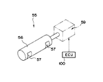
図1,図2に示すように、本実施例においては、複数設けられる掃気通路52にそれぞれ掃気制御バルブ55が設けられている。この掃気制御バルブ55は、ロータリー式のバルブであり、円柱状の回転体56に径方向に貫通する矩形状の連通孔57,57を穿設して構成され、それぞれの連通孔57が掃気通路上に配置されるようになっている。この回転体56の一端面には駆動シャフト58が同軸上に一体に設けられており、駆動シャフト58にはバルブ駆動モータ59が連結されている。バルブ駆動モータ59が駆動されると、バルブ駆動モータ59の駆動力が駆動シャフト58を介して回転体56に伝達され、回転体56が回転駆動されるようになっている。
As shown in FIGS. 1 and 2, in this embodiment, a scavenging
回転体56が回転することにより、連通孔57の開口位置が変位し、掃気通路52が開閉されるようになっている。また、この連通孔57の変位により、掃気制御バルブ55は開度Thscを可変にして掃気通路52を開放できるようになっている。
When the
この掃気制御バルブ55による掃気通路52の開閉は、図3に示すように、クランクシャフト15の回転と同期して行われる。ECU100は、クランク角検出センサからの検出信号に基づき、クランク角θCAが180度になる直前の所定の角度、すなわちピストン14の下動行程において掃気ポート51が開放されてさらにクランクシャフト15が回転して下死点近傍に位置したときに、掃気通路バルブ55による掃気通路52の開放作動が開始されるようにバルブ駆動モータ59の駆動制御を行う。掃気通路バルブ55は、回転体55の回転に伴って連通孔57の回転位置を変位させて開度Thscを増加させながら掃気通路52を開放する。そして、掃気通路バルブ55の開度が所定の最大開度ThscmとなったときにECU100によりバルブ駆動モータ59の駆動を停止し、駆動シャフト58および回転体56の回転が停止される。さらに、ECU100により、ピストン14の上動行程により掃気ポート51が閉塞された後に、掃気制御バルブ55により掃気通路52が全閉されるようにバルブ駆動モータ59が逆回転に駆動制御されて掃気制御バルブ55により早期津ロ52が全閉される。このように、一連の掃気制御バルブ55の作動がクランクシャフト15の回転に同期して行われる。
The opening and closing of the scavenging passage 52 by the scavenging
また、エンジンEの回転速度が増加すると各行程に要する時間が短くなる。従って、ECU100はエンジン回転速度センサS1からの検出信号に基づき、クランクシャフト15の回転速度に応じた駆動速度でバルブ駆動モータを駆動制御するように構成されている。
Further, as the rotational speed of the engine E increases, the time required for each stroke becomes shorter. Therefore, the
なお、このような作動タイミングで開閉駆動される掃気制御バルブ55により、ピストン14の下動行程において掃気ポート51が開放されても掃気制御バルブ55により掃気通路52は閉塞されたままであるため、従来よりも掃気ポート51が開放されてからのクランクケース15の内圧の下降が緩和される。そしてピストン14が下死点近傍に到達して掃気制御バルブ55が掃気通路52を開放するように作動し、クランククケース12の内部空間12aと燃焼室10aとが連通するようになると、クランクケース12の内圧が下降するとともに、クランクケース12の内部空間12aに圧縮された新気が掃気通路52を介して燃焼室10a内に導かれるようになっている。
The scavenging
このような作動タイミングで作動する掃気制御バルブ55において、最大開度Thscmは、スロットルバルブ45のスロットル開度に対応して設定されている。ECU100は、スロットル開度センサS2からの検出信号を受けると、この検出信号に基づいてECU100の記憶部に予め記憶されたスロットルバルブ45のスロットル開度に対応付けられた最大開度Thscmのマップから掃気制御バルブ55の最大開度Thscmを決定し、決定された最大開度Thscmで掃気制御バルブ55が掃気通路52を上記作動タイミングで開放するように駆動信号をバルブ駆動モータ59に出力する。そして、このような駆動信号を受けたバルブ駆動モータ59が掃気制御バルブ55を回転駆動し、開度Thscを上昇させてECU100により決定される最大開度Thscmで掃気通路52が開放される。
In the scavenging
また、ECU100の記憶部に記憶されるスロットル開度と最大開度Thscmとを対応付けたマップは、スロットルバルブ45のスロットル開度が大きいときに掃気制御バルブ55の最大開度Thscmが大きく、スロットルバルブ45のスロットル開度が小さいときに掃気制御バルブ55の最大開度Thscmが小さくなるように設定される。すなわち、エンジンEの負荷が大きいときには掃気制御バルブ55の最大開度Thscmが大きく、エンジンEの負荷が小さいときには掃気制御バルブ55の最大開度Thscmが小さくなるように設定されている。
Further, the map in which the throttle opening and the maximum opening Thscm stored in the storage unit of the
なお、このような掃気制御バルブ55の作動は、エンジンの回転速度が高回転領域となって所定の回転速度を超えた場合、クランクシャフト15の回転に同期させて所望の最大開度Thscmで掃気通路52を開放するように掃気制御バルブ55を作動させることが困難となり、行われるべき掃気作用が達成されなくなるおそれがある。このため、ECU100は、エンジン回転速度センサS1からの検出信号によりエンジンEが所定の回転速度を超えて回転していると判断したときには、図3に示すように掃気制御バルブ55を作動させる駆動制御信号を出力せず、掃気制御バルブ55の開度Thscが常に全開状態となるような駆動制御信号をバルブ駆動モータ59に出力する。すなわち、図3に示す作動タイミングで掃気制御バルブ55を作動させる開閉駆動制御は、ECU100によりエンジンEの回転速度が上記所定の回転速度以下であると判断されたときにおいて行われる。
The operation of the scavenging
このような、本実施例の2サイクルエンジンの構成によると、ECU100による掃気制御バルブによるバルブ駆動モータ59の駆動制御により、クランクシャフト15が回転して下死点近傍に位置するときに掃気制御バルブ55による掃気通路52の開放を行うようになっている。
According to such a configuration of the two-cycle engine of the present embodiment, the scavenging control valve is operated when the
従来は下動行程中に掃気ポート51が開口されることでクランクケース12の内圧が下降するとともに、上動行程中にシリンダ空間11aが圧縮されてクランクケース12の内部空間12aが負圧になることで掃気通路52への吸い戻しが生じていたが、本構成によると、掃気ポート51が開口されてもピストン14が下死点近傍に位置するまでは掃気制御バルブ55により掃気通路52が閉塞されるため、クランクケース12の内圧が下降せず、掃気制御バルブ55が開放されてからピストン14の上動行程においてクランクケース12で圧縮された新気がシリンダ空間11aに供給される。これにより、ピストン14の上動行程における掃気通路52への吸い戻しが防止、低減され、エンジン出力の低下を防止できるとともに、中低負荷領域での不整燃焼の防止を図ることができる。これにより、燃費の向上が図られる。
Conventionally, when the scavenging port 51 is opened during the downward stroke, the internal pressure of the
また、排気制御バルブ35による排気通路32の閉塞により、自着火燃焼を可能に構成された2サイクルエンジンにおいては、このような掃気制御バルブ55の作動により自着火燃焼に利用される既燃気の熱エネルギのクランクケース側への漏れを低減できる。このため、従来よりも自着火燃焼を的確に行えるようになるとともに、自着火燃焼を制御可能な運転領域の下限側を拡大することができる。これにより、燃費を向上させることができる。
Further, in a two-cycle engine configured to be able to perform self-ignition combustion by closing the exhaust passage 32 by the
また、スロットルバルブ45のスロットル開度に応じて掃気制御バルブ55の開度Thscを決定するようになっており、スロットルバルブ45スロットル開度が小さいときには掃気制御バルブ55の開度Thscを小さくし、スロットル開度Thscが大きいときには掃気制御バルブ55の開度Thscを大きくするようにECU100によるバルブ駆動モータ59の駆動制御が行われる。これにより、要求される負荷に応じて必要な掃気量でクランクケース12から燃焼室10aに新気を供給することができ、エンジンEを安定して作動させることができる。
Further, the opening degree Thsc of the scavenging
また、このように掃気制御バルブ55の開度Thscを制御することで、吹き戻しが生じても低負荷時においては開度Thscが小さいため、その吹き戻し量を低減することができる。本実施例のように自着火燃焼を行わせることを可能にしたエンジンEにおいては、低負荷時の吹き戻し量が低減されることにより、熱エネルギの漏れをより効果的に防ぐことになり、自着火燃焼可能な運転領域の拡大を図ることができる。
In addition, by controlling the opening degree Thsc of the scavenging
また、エンジン回転速度センサからの検出信号に基づいてバルブ駆動モータ59の駆動速度を適正に設定して掃気制御バルブ55が作動するが、高回転領域にあるときはエンジンEの回転速度に追従させて排気制御バルブを開閉駆動させることが困難となり、充分な掃気作用が行われなくなるおそれがある。ここで、本実施例のように、エンジンの回転速度が所定の回転速度を超える場合に、排気制御バルブ55が常に掃気通路52の開度Thscが全開となるように駆動制御することで、エンジンの回転速度が小さいときにおいては上記吸い戻しを効果的に防止するとともに、エンジンの回転速度が大きいときにはエンジンの作動を安定して行わせることができる2サイクルエンジンを提供することができる。
Further, the scavenging
また、本実施例においては、自着火燃焼を行わせるために設けられた排気制御バルブ35の駆動制御においても、スロットル開度センサS2が検出するスロットルバルブ45の開度に基づいて駆動制御を行うように構成しており、装置構成を複雑化することなく本発明に係る2サイクルエンジンを構成することができる。
In the present embodiment, the drive control of the
なお、本発明に係る2サイクルエンジンは、上記実施例の形態に限られない。例えば、燃料を噴射するシステムとして、燃焼室内で圧縮されたエアで燃料噴射のアシストを行う形態としたが、外部エアをエアポンプで圧縮して燃料噴射弁に供給する形態であってもよい。また、燃焼室内に直接燃料を噴射する形態に限らず、吸気マニホールド内において新気に燃料を混合させる形態であってもよい。どのような形態であっても本発明を同様に実施可能であり、同様の効果を得ることができる。 The two-cycle engine according to the present invention is not limited to the embodiment described above. For example, as a system for injecting fuel, the fuel injection assist is performed with air compressed in the combustion chamber, but external air may be compressed with an air pump and supplied to the fuel injection valve. Further, the present invention is not limited to the mode in which the fuel is directly injected into the combustion chamber, but may be a mode in which fuel is mixed with fresh air in the intake manifold. The present invention can be similarly implemented in any form, and the same effect can be obtained.
また、上記実施例では、本発明に係る2サイクルエンジンを二輪車に搭載した場合を例示したが、他の装置の内燃機関として搭載しても同様に実施可能であり、同様の効果を得ることができる。 Further, in the above embodiment, the case where the two-cycle engine according to the present invention is mounted on a two-wheeled vehicle is illustrated, but the present invention can be similarly implemented even when mounted as an internal combustion engine of another device, and the same effect can be obtained. it can.
E エンジン
S1 エンジン回転速度センサ(エンジン回転速度検出手段)
S2 スロットル開度センサ(負荷検出手段、スロットル開度検出手段)
11 シリンダボディ
11a シリンダ空間
12 クランクケース
12a 内部空間
14 ピストン
15 クランクシャフト
31 排気ポート
32 排気通路
35 排気制御バルブ(排気弁手段)
45 スロットルバルブ
51 掃気ポート
52 掃気通路
55 掃気制御バルブ(掃気弁手段)
59 バルブ駆動モータ(掃気弁手段)
100 ECU(掃気弁駆動制御手段、排気弁駆動制御手段)
E engine S1 engine rotation speed sensor (engine rotation speed detection means)
S2 Throttle opening sensor (load detection means, throttle opening detection means)
11
45 Throttle valve 51 Scavenging port 52
59 Valve drive motor (scavenging valve means)
100 ECU (scavenging valve drive control means, exhaust valve drive control means)
Claims (5)
前記シリンダに結合されて内部空間が前記シリンダ空間に連通し、前記内部空間に前記ピストンの往復動を受けて回転駆動されるクランクシャフトを収容したクランクケースと、
前記シリンダ空間の内周面に開口形成されて前記ピストンの往復動に伴って開閉される掃気ポートおよび前記クランクケースの内部空間を連通する掃気通路とを有し、
前記クランクケースの内部空間のエアを前記掃気通路を介して前記シリンダ空間に取り入れ、前記シリンダ空間内の燃料混合気を燃焼させるように構成された2サイクルエンジンにおいて、
前記掃気通路内に設けられて前記掃気通路を開閉可能な掃気弁手段と、
エンジンの回転速度を検出する回転速度検出手段と、
エンジンの負荷を検出する負荷検出手段と、
前記ピストンが下死点近傍に位置したときに、前記回転速度検出手段により検出されるエンジンの回転速度に基づく速度で、前記負荷検出手段により検出されるエンジンの負荷に基づく開度で前記掃気通路を開放するように前記掃気弁手段の開閉駆動制御を行う掃気弁駆動制御手段とを設けて構成されることを特徴とする2サイクルエンジン。 A cylinder having a cylinder space and containing a piston reciprocally movable in the cylinder space;
A crankcase that is coupled to the cylinder and communicates with the cylinder space, and that houses a crankshaft that is rotationally driven by the reciprocation of the piston in the internal space;
A scavenging port that is formed in an inner peripheral surface of the cylinder space and is opened and closed as the piston reciprocates; and a scavenging passage that communicates with the internal space of the crankcase;
In a two-cycle engine configured to take air in an internal space of the crankcase into the cylinder space via the scavenging passage, and to burn a fuel mixture in the cylinder space,
Scavenging valve means provided in the scavenging passage and capable of opening and closing the scavenging passage;
A rotational speed detecting means for detecting the rotational speed of the engine;
Load detection means for detecting engine load;
When the piston is located near the bottom dead center, the scavenging passage is at a speed based on the engine speed detected by the speed detecting means and at an opening based on the engine load detected by the load detecting means. A two-cycle engine comprising: a scavenging valve drive control means for performing opening / closing drive control of the scavenging valve means so as to open the valve.
前記排気弁手段の開閉駆動制御を行う排気弁駆動制御手段とを有し、
前記排気弁駆動制御手段による前記排気弁手段の開閉駆動制御により前記シリンダ空間内の燃料混合気を自着火燃焼可能に構成されることを特徴とする2サイクルエンジン。 An exhaust valve means provided in an exhaust passage connected to an exhaust port formed in an inner peripheral surface of the cylinder space and capable of opening and closing the exhaust passage;
Exhaust valve drive control means for performing open / close drive control of the exhaust valve means,
A two-cycle engine configured to be capable of self-ignition combustion of a fuel mixture in the cylinder space by opening / closing drive control of the exhaust valve means by the exhaust valve drive control means.
Priority Applications (1)
| Application Number | Priority Date | Filing Date | Title |
|---|---|---|---|
| JP2005103389A JP2006283629A (en) | 2005-03-31 | 2005-03-31 | Two cycle engine |
Applications Claiming Priority (1)
| Application Number | Priority Date | Filing Date | Title |
|---|---|---|---|
| JP2005103389A JP2006283629A (en) | 2005-03-31 | 2005-03-31 | Two cycle engine |
Publications (2)
| Publication Number | Publication Date |
|---|---|
| JP2006283629A true JP2006283629A (en) | 2006-10-19 |
| JP2006283629A5 JP2006283629A5 (en) | 2008-01-24 |
Family
ID=37405815
Family Applications (1)
| Application Number | Title | Priority Date | Filing Date |
|---|---|---|---|
| JP2005103389A Pending JP2006283629A (en) | 2005-03-31 | 2005-03-31 | Two cycle engine |
Country Status (1)
| Country | Link |
|---|---|
| JP (1) | JP2006283629A (en) |
Cited By (5)
| Publication number | Priority date | Publication date | Assignee | Title |
|---|---|---|---|---|
| JP2008180221A (en) * | 2007-01-25 | 2008-08-07 | Andreas Stihl Ag & Co Kg | Operation method of internal combustion engine |
| US8770159B2 (en) | 2008-09-24 | 2014-07-08 | Makita Corporation | Stratified scavenging two-stroke engine |
| KR20150023917A (en) * | 2012-10-03 | 2015-03-05 | 가부시키가이샤 아이에이치아이 | Uniflow scavenging 2-cycle engine |
| US9206736B2 (en) | 2012-12-28 | 2015-12-08 | Makita Corporation | Stratified scavenging two-stroke engine |
| CN114592966A (en) * | 2022-05-11 | 2022-06-07 | 四川迅联达智能科技有限公司 | All-air scavenging engine |
Citations (6)
| Publication number | Priority date | Publication date | Assignee | Title |
|---|---|---|---|---|
| JPS62288316A (en) * | 1986-06-05 | 1987-12-15 | Mitsubishi Heavy Ind Ltd | Scavenging hole control valve driving device for internal combustion engine |
| JPH0771279A (en) * | 1993-01-08 | 1995-03-14 | Honda Motor Co Ltd | Combustion controller of spark ignition type two-cycle engine |
| JPH07224667A (en) * | 1994-02-16 | 1995-08-22 | Suzuki Motor Corp | Two-cycle engine |
| JPH09217628A (en) * | 1996-02-13 | 1997-08-19 | Yamaha Motor Co Ltd | Two cycle engine |
| JPH09291827A (en) * | 1996-04-30 | 1997-11-11 | Yamaha Motor Co Ltd | Two-cycle engine |
| JP2002147237A (en) * | 2000-11-14 | 2002-05-22 | Fuji Heavy Ind Ltd | Combustion control device for two-cycle engine |
-
2005
- 2005-03-31 JP JP2005103389A patent/JP2006283629A/en active Pending
Patent Citations (6)
| Publication number | Priority date | Publication date | Assignee | Title |
|---|---|---|---|---|
| JPS62288316A (en) * | 1986-06-05 | 1987-12-15 | Mitsubishi Heavy Ind Ltd | Scavenging hole control valve driving device for internal combustion engine |
| JPH0771279A (en) * | 1993-01-08 | 1995-03-14 | Honda Motor Co Ltd | Combustion controller of spark ignition type two-cycle engine |
| JPH07224667A (en) * | 1994-02-16 | 1995-08-22 | Suzuki Motor Corp | Two-cycle engine |
| JPH09217628A (en) * | 1996-02-13 | 1997-08-19 | Yamaha Motor Co Ltd | Two cycle engine |
| JPH09291827A (en) * | 1996-04-30 | 1997-11-11 | Yamaha Motor Co Ltd | Two-cycle engine |
| JP2002147237A (en) * | 2000-11-14 | 2002-05-22 | Fuji Heavy Ind Ltd | Combustion control device for two-cycle engine |
Cited By (8)
| Publication number | Priority date | Publication date | Assignee | Title |
|---|---|---|---|---|
| JP2008180221A (en) * | 2007-01-25 | 2008-08-07 | Andreas Stihl Ag & Co Kg | Operation method of internal combustion engine |
| US8770159B2 (en) | 2008-09-24 | 2014-07-08 | Makita Corporation | Stratified scavenging two-stroke engine |
| US9249716B2 (en) | 2008-09-24 | 2016-02-02 | Makita Corporation | Stratified scavenging two-stroke engine |
| KR20150023917A (en) * | 2012-10-03 | 2015-03-05 | 가부시키가이샤 아이에이치아이 | Uniflow scavenging 2-cycle engine |
| KR101725850B1 (en) | 2012-10-03 | 2017-04-11 | 가부시키가이샤 아이에이치아이 | Uniflow scavenging 2-cycle engine |
| US9206736B2 (en) | 2012-12-28 | 2015-12-08 | Makita Corporation | Stratified scavenging two-stroke engine |
| US9869235B2 (en) | 2012-12-28 | 2018-01-16 | Makita Corporation | Stratified scavenging two-stroke engine |
| CN114592966A (en) * | 2022-05-11 | 2022-06-07 | 四川迅联达智能科技有限公司 | All-air scavenging engine |
Similar Documents
| Publication | Publication Date | Title |
|---|---|---|
| US7395813B2 (en) | Method of controlling the intake and/or the exhaust of at least one deactivated cylinder of an internal-combustion engine | |
| EP1379763B1 (en) | A four stroke auto-ignition engine | |
| EP0980969A2 (en) | Method for operating a two-stroke in-cylinder injection engine and such an engine | |
| JP2004162707A (en) | Stop control method for internal combustion engine, and internal combustion engine suitable for execution of the method | |
| JP2013510261A (en) | Two-stroke internal combustion engine with variable compression ratio and exhaust port shutter and method of operating such an engine | |
| CN103089489B (en) | The internal-combustion engine that can run under homogeneous charge compression-ignition pattern | |
| JPH05179986A (en) | Method of operating internal combustion engine | |
| US5083533A (en) | Two-stroke-cycle engine with variable valve timing | |
| JP2006283629A (en) | Two cycle engine | |
| JP4944131B2 (en) | Two-cycle internal combustion engine with variable compression ratio and exhaust port shutter | |
| WO2021177010A1 (en) | Two-cycle internal combustion engine and engine work machine | |
| JP2003254199A (en) | Cylinder fuel injection type internal combustion engine | |
| US5189996A (en) | Two-stroke-cycle engine with variable valve timing | |
| US6145483A (en) | Two-cycle internal combustion engine | |
| JP2009215913A (en) | Spark ignition type internal combustion engine | |
| JP4306462B2 (en) | 4-cycle internal combustion engine | |
| JP2006348809A (en) | Internal combustion engine | |
| JP2006257999A (en) | Internal combustion engine | |
| JPH04166656A (en) | Sub-chamber type engine having exhaust gas recirculation device | |
| JP2007064027A (en) | Auxiliary chamber type internal combustion engine | |
| JP4760739B2 (en) | Automatic stop / start system for internal combustion engine | |
| JPH09250429A (en) | Fuel injecting/supplying type engine | |
| JPH09242570A (en) | Spark ignition type two-stroke internal combustion engine with combustion control device | |
| JPH07259707A (en) | Fuel injection method in fuel injection type two-cycle engine | |
| JP2005337218A (en) | Variable cycle internal combustion engine |
Legal Events
| Date | Code | Title | Description |
|---|---|---|---|
| A521 | Written amendment |
Free format text: JAPANESE INTERMEDIATE CODE: A523 Effective date: 20071205 |
|
| A621 | Written request for application examination |
Free format text: JAPANESE INTERMEDIATE CODE: A621 Effective date: 20071205 |
|
| A977 | Report on retrieval |
Free format text: JAPANESE INTERMEDIATE CODE: A971007 Effective date: 20090703 |
|
| A131 | Notification of reasons for refusal |
Free format text: JAPANESE INTERMEDIATE CODE: A131 Effective date: 20090710 |
|
| A521 | Written amendment |
Free format text: JAPANESE INTERMEDIATE CODE: A523 Effective date: 20090903 |
|
| A131 | Notification of reasons for refusal |
Free format text: JAPANESE INTERMEDIATE CODE: A131 Effective date: 20100205 |
|
| A02 | Decision of refusal |
Free format text: JAPANESE INTERMEDIATE CODE: A02 Effective date: 20100604 |