WO2021176973A1 - Gripping tool - Google Patents
Gripping tool Download PDFInfo
- Publication number
- WO2021176973A1 WO2021176973A1 PCT/JP2021/004852 JP2021004852W WO2021176973A1 WO 2021176973 A1 WO2021176973 A1 WO 2021176973A1 JP 2021004852 W JP2021004852 W JP 2021004852W WO 2021176973 A1 WO2021176973 A1 WO 2021176973A1
- Authority
- WO
- WIPO (PCT)
- Prior art keywords
- rotation
- link arm
- link
- gripping tool
- gripping
- Prior art date
Links
- 230000007246 mechanism Effects 0.000 claims abstract description 37
- 210000000078 claw Anatomy 0.000 claims description 63
- 238000013459 approach Methods 0.000 claims description 7
- 230000000903 blocking effect Effects 0.000 claims description 6
- 230000004044 response Effects 0.000 claims description 3
- 230000001105 regulatory effect Effects 0.000 description 18
- 229910000831 Steel Inorganic materials 0.000 description 13
- 239000010959 steel Substances 0.000 description 13
- 230000004048 modification Effects 0.000 description 7
- 238000012986 modification Methods 0.000 description 7
- 238000000926 separation method Methods 0.000 description 7
- 238000010276 construction Methods 0.000 description 2
- 230000000694 effects Effects 0.000 description 2
- 230000009471 action Effects 0.000 description 1
- 230000008859 change Effects 0.000 description 1
- 238000007796 conventional method Methods 0.000 description 1
- 230000006872 improvement Effects 0.000 description 1
- 238000000034 method Methods 0.000 description 1
Images


Classifications
-
- B—PERFORMING OPERATIONS; TRANSPORTING
- B25—HAND TOOLS; PORTABLE POWER-DRIVEN TOOLS; MANIPULATORS
- B25J—MANIPULATORS; CHAMBERS PROVIDED WITH MANIPULATION DEVICES
- B25J9/00—Programme-controlled manipulators
- B25J9/10—Programme-controlled manipulators characterised by positioning means for manipulator elements
- B25J9/106—Programme-controlled manipulators characterised by positioning means for manipulator elements with articulated links
- B25J9/1065—Programme-controlled manipulators characterised by positioning means for manipulator elements with articulated links with parallelograms
-
- H—ELECTRICITY
- H02—GENERATION; CONVERSION OR DISTRIBUTION OF ELECTRIC POWER
- H02G—INSTALLATION OF ELECTRIC CABLES OR LINES, OR OF COMBINED OPTICAL AND ELECTRIC CABLES OR LINES
- H02G1/00—Methods or apparatus specially adapted for installing, maintaining, repairing or dismantling electric cables or lines
- H02G1/02—Methods or apparatus specially adapted for installing, maintaining, repairing or dismantling electric cables or lines for overhead lines or cables
- H02G1/04—Methods or apparatus specially adapted for installing, maintaining, repairing or dismantling electric cables or lines for overhead lines or cables for mounting or stretching
-
- B—PERFORMING OPERATIONS; TRANSPORTING
- B25—HAND TOOLS; PORTABLE POWER-DRIVEN TOOLS; MANIPULATORS
- B25B—TOOLS OR BENCH DEVICES NOT OTHERWISE PROVIDED FOR, FOR FASTENING, CONNECTING, DISENGAGING OR HOLDING
- B25B5/00—Clamps
- B25B5/04—Clamps with pivoted jaws
-
- B—PERFORMING OPERATIONS; TRANSPORTING
- B25—HAND TOOLS; PORTABLE POWER-DRIVEN TOOLS; MANIPULATORS
- B25B—TOOLS OR BENCH DEVICES NOT OTHERWISE PROVIDED FOR, FOR FASTENING, CONNECTING, DISENGAGING OR HOLDING
- B25B5/00—Clamps
- B25B5/14—Clamps for work of special profile
-
- B—PERFORMING OPERATIONS; TRANSPORTING
- B25—HAND TOOLS; PORTABLE POWER-DRIVEN TOOLS; MANIPULATORS
- B25B—TOOLS OR BENCH DEVICES NOT OTHERWISE PROVIDED FOR, FOR FASTENING, CONNECTING, DISENGAGING OR HOLDING
- B25B5/00—Clamps
- B25B5/14—Clamps for work of special profile
- B25B5/147—Clamps for work of special profile for pipes
-
- B—PERFORMING OPERATIONS; TRANSPORTING
- B25—HAND TOOLS; PORTABLE POWER-DRIVEN TOOLS; MANIPULATORS
- B25J—MANIPULATORS; CHAMBERS PROVIDED WITH MANIPULATION DEVICES
- B25J15/00—Gripping heads and other end effectors
- B25J15/0033—Gripping heads and other end effectors with gripping surfaces having special shapes
- B25J15/0038—Cylindrical gripping surfaces
Definitions
- the present invention relates to a gripping tool.
- Patent Document 1 discloses a wire grip portion of a wire cutting tool, which is a gripping tool of this type.
- the electric wire grip portion of Patent Document 1 includes a mounting portion in which a receiving piece is integrally formed, two swing levers, and a grip portion. Each of the two swing levers is pivotally supported on the mounting portion on one end side so as to be rotatable.
- the grip portion grips the electric wire between the two swing levers and the receiving piece by rotating to one of the two swing levers.
- the wire gripper further includes a locking means for restricting the rotation of the operating portion to the other side in order to prevent the gripping from being released after the gripping of such a linear body.
- the locking means acts on one of the two swing levers to regulate the rotation so that the swing lever does not rotate.
- the locking means generally has a screw shaft provided so as to be able to move forward and backward with respect to a part of one swing lever, and by moving the screw shaft forward and backward.
- the tip of the screw shaft abuts on one swing lever to regulate the rotation of the other swing lever in the other direction. Therefore, when the rotation of one swing lever is regulated by using the locking means, it is necessary to rotate the screw shaft. Therefore, when the work of attaching the wire gripper to the linear body is performed, it takes a lot of time and effort to rotate the screw shaft, and there is room for improvement.
- the present invention has been made in view of the above circumstances, and an object of the present invention is to provide a gripping tool capable of restricting the rotation of a link member with a simple operation.
- this gripping tool includes a main body portion, a link member, a connecting member, a fixed side grip portion, and a movable side grip portion.
- the link member is rotatably supported by the main body.
- the connecting member is connected to the link member.
- the fixed-side grip portion is provided on the main body portion.
- the movable side grip portion is connected to the link member so as to face the fixed side grip portion, and can move in a direction closer to or away from the fixed side grip portion in conjunction with the movement of the connecting member. be.
- the gripping tool grips and holds a linear body by the fixed-side gripping portion and the movable-side gripping portion.
- the gripping tool includes a one-way clutch that prevents rotation in a certain direction and allows rotation in the opposite direction with respect to the rotation of the link member or the rotation of another member that is interlocked with the rotation of the link member. By blocking the rotation of the one-way clutch, either one of the movement in the direction in which the movable side grip portion approaches the fixed side grip portion and the movement in the direction in which the movable side grip portion is separated from the fixed side grip portion is restricted.
- the gripping tool described above preferably has the following configuration. That is, the gripping tool includes an operation unit rotatably provided on the connecting member.
- the operating portion has a contact portion capable of contacting the link member.
- the contact portion moves along an arcuate locus in response to the operation of the operation portion.
- the link member pushes the contact portion in conjunction with the movement of the movable side grip portion in a direction away from the fixed side grip portion.
- the one-way clutch prevents the operation portion from rotating when the contact portion is pushed by the link member, and allows rotation in the opposite direction.
- the gripping tool includes an urging member that rotationally urges the operating portion in a direction in which the contact portion approaches the link member.
- the gripping tool is configured to be capable of a switching operation for releasing the rotation blocking by the one-way clutch or a switching operation for reversing the direction in which the rotation is blocked.
- the gripping tool described above preferably has the following configuration. That is, the one-way clutch includes a ratchet wheel, a claw member, and an elastic member.
- the ratchet wheel is fixedly arranged with respect to the connecting member.
- the claw member is rotatably supported with respect to the operating portion.
- the elastic member generates an elastic force acting on the claw member.
- the gripping tool described above preferably has the following configuration. That is, a plurality of the link members are provided.
- the main body, the link member, and the connecting member constitute a parallel link mechanism.
- the posture of the connecting member is constant even if the link member rotates, so that the rotation of the link member can be reliably regulated with a simple configuration.
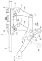
- FIG. 5 is a side view showing an overall configuration of a wire gripper according to an embodiment of the present invention.
- the cross-sectional perspective view which shows the structure of the regulation part in a wire gripper in detail.
- FIG. 3 is a cross-sectional view of a regulation unit showing a state corresponding to FIG.
- a side view showing a state in which the connecting member is pulled from the state of FIG. 1 and the linear body is grasped.
- a cross-sectional view showing the state of the regulation part before being locked by the operation lever.
- the cross-sectional view which shows the state of the regulation part after being locked by an operation lever.
- the side view which shows the 1st modification of a wire gripper.
- FIG. 1 is a side view showing the overall configuration of the wire gripping device 1 according to the embodiment of the present invention.
- the wire gripping device (grasping tool) 1 shown in FIG. 1 is a tool capable of gripping a linear body (electric wire, wire, etc.) 3.
- the wire gripping device 1 is applied to, for example, a device (wire tensioning device) that pulls the linear body 3 when construction work related to the linear body 3 is performed. When using this device, the wire gripping device 1 grips the linear body 3 and is attached to the linear body 3.
- the electric wire as the linear body 3 is stretched in the horizontal direction, and the wire gripper 1 is used to sandwich the linear body 3 in the vertical direction.
- the longitudinal direction of the linear body 3 may be referred to as a front-rear direction
- a direction perpendicular to both the front-rear direction and the up-down direction may be referred to as a left-right direction.
- this name is for convenience only and does not limit the positional relationship of each part.
- the wire gripper 1 includes a main body portion 5, two link arms (link members) 7, a fixed side grip portion (fixed side grip portion) 9, and a movable side grip portion (movable).
- a side grip portion) 11 and a regulation portion 13 are provided.
- the main body 5 is a base portion to which various parts constituting the wire gripping device 1 are attached.
- a fixed-side gripping wire portion 9 is integrally formed on the main body portion 5.
- the fixed side gripping portion 9 is provided so as to extend in the front-rear direction.
- a first groove portion 15 formed elongated in the front-rear direction is formed on the lower surface of the fixed-side gripping portion 9. The lower side of the first groove portion 15 is open so that the upper portion of the linear body 3 can be accommodated.
- the two link arms 7 are arranged at appropriate intervals in the front-rear direction.
- the configurations of the two link arms 7 are substantially the same.
- first link arm 7A the one located on one side in the front-rear direction
- second link arm 7B the one located on the other side in the front-rear direction
- the first link arm 7A and the second link arm 7B are provided so as to project downward from the main body 5, respectively.
- the first link arm 7A is rotatably supported by the main body 5 about the first shaft 21.
- the second link arm 7B is rotatably supported by the main body 5 about the second shaft 23.
- the movable side gripping portion 11 is provided so as to extend in the front-rear direction.
- a second groove portion 25 formed elongated in the front-rear direction is formed on the upper surface of the movable side gripping portion 11.
- the second groove portion 25 has an open upper side and can accommodate the lower portion of the linear body 3.
- the movable side gripping portion 11 is arranged below the fixed side gripping portion 9.
- the movable side grip portion 11 is arranged so that the open portion of the second groove portion 25 faces the open portion of the first groove portion 15 of the fixed side grip portion 9 in the vertical direction.
- the movable side gripping portion 11 is arranged above each of the first axis 21 and the second axis 23.
- the movable side gripping portion 11 is separated from the first axis 21 in the front-rear direction on the first link arm 7A and one side in the front-rear direction from the second axis 23 in the second link arm 7B. Connect the position.
- the movable side gripping portion 11 is rotatably attached to each of the first link arm 7A and the second link arm 7B.
- the main body portion 5, the first link arm 7A, the second link arm 7B, and the movable side gripping portion 11 constitute a parallel link mechanism.
- a connecting member 27 is provided so as to connect the lower end of the first link arm 7A and the lower end of the second link arm 7B.
- the connecting member 27 is formed in an elongated shape, and is arranged so that its longitudinal direction is substantially oriented in the front-rear direction.
- the third axis 31 is arranged at a position below the first axis 21 in the first link arm 7A.
- the fourth axis 33 is arranged at a position on the second link arm 7B below the second axis 23.
- One end of the connecting member 27 in the longitudinal direction is rotatably attached to the third shaft 31.
- the intermediate portion of the connecting member 27 in the longitudinal direction is rotatably attached to the fourth shaft 33.
- the main body 5, the first link arm 7A, the second link arm 7B, and the connecting member 27 constitute a parallel link mechanism.
- the other end of the connecting member 27 in the longitudinal direction is configured to be connectable to the above-mentioned device (stretching device).
- the device can pull the connecting member 27 connected to the device.
- the first link arm 7A rotates about the first axis 21 and the second link arm 7B rotates about the second axis 23.
- the movable side gripping portion 11 connected to each of the first link arm 7A and the second link arm 7B is substantially in the vertical direction so as to be close to or separated from the fixed side gripping portion 9. Moving. By moving the movable side gripping portion 11 so as to be close to the fixed side gripping portion 9, the fixed side gripping portion 9 and the movable side gripping portion 11 grip and hold the linear body 3. Can be done.
- the direction in which the movable side gripping portion 11 is brought closer to the fixed side gripping portion 9 is referred to as a "grasping direction", and the opposite direction is referred to as a "grasping direction”.
- the gripping direction is clockwise and the releasing direction is counterclockwise.
- the regulation unit 13 is provided between the second link arm 7B and the connecting member 27.
- the regulating unit 13 regulates the operation of the second link arm 7B (rotation around the second axis 23) in the parallel link mechanism described above, so that the movable side gripping portion 11 suddenly moves from the fixed side gripping portion 9. Can be held so that it does not separate from.
- FIG. 2 is a cross-sectional perspective view showing in detail the configuration of the regulating portion 13 in the wire gripping device 1.
- FIG. 3 is a cross-sectional view of the regulation unit 13 showing a state corresponding to FIG.
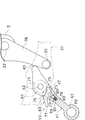
- FIG. 4 is a side view showing a state in which the connecting member 27 is pulled from the state of FIG. 1 and the linear body 3 is grasped.
- FIG. 5 is a cross-sectional view showing a state of the regulating portion 13 before being locked by the operating lever 41.
- FIG. 6 is a cross-sectional view showing a state of the regulating portion 13 after being locked by the operating lever 41.
- the connecting member 27 has a first member 37 and a second member 39, as shown in FIG.
- the first member 37 and the second member 39 have shapes corresponding to each other, and are configured substantially symmetrically.
- the first member 37 and the second member 39 are arranged at appropriate intervals in the left-right direction and are fixed to each other.
- the lower end of the first link arm 7A and the lower end of the second link arm 7B are arranged in the space between the first member 37 and the second member 39.
- a part or all of the connecting member 27 is shown transparently by a chain line in FIGS. 2 and 3 and the like.
- the above-mentioned regulating portion 13 is arranged in the space between the first member 37 and the second member 39 at a position corresponding to the intermediate portion in the longitudinal direction of the connecting member 27.
- the regulation unit 13 includes an operation lever (operation unit) 41 and a ratchet mechanism (one-way clutch) 47.
- the operation lever 41 is configured as an elongated member.
- a rotating shaft 53 extending in the left-right direction is attached to the middle portion of the operating lever 41 in the longitudinal direction.
- the operating lever 41 is rotatably supported with respect to the first member 37 and the second member 39 via the rotating shaft 53.
- One end of the operating lever 41 in the longitudinal direction projects downward from the connecting member 27.
- An operation hole 51 into which a tool or the like can be inserted is formed at the end of the protruding portion. The user of the wire gripper 1 can rotate the operation lever 41 around the rotation shaft 53 by using a tool or the like inserted in the operation hole 51.
- a contact portion 43 is integrally formed at an end portion opposite to the side on which the operation hole 51 is formed.
- the contact portion 43 rotates integrally with the operating lever 41. Therefore, by rotating the operation lever 41, the contact portion 43 moves along an arc-shaped locus centered on the rotation shaft 53.
- the contact portion 43 can come into contact with the portion of the second link arm 7B between the second shaft 23 and the fourth shaft 33. At this time, the surface of the second link arm 7B that contacts the contact portion 43 is the surface of the second link arm 7B on the downstream side in the gripping direction.
- the ratchet mechanism 47 is provided between the connecting member 27 and the operating lever 41.
- the ratchet mechanism 47 can hold the operating lever 41 so that the operating lever 41 does not rotate relative to the connecting member 27.
- the ratchet mechanism 47 includes a ratchet wheel 61, a claw member 63, and a pressing portion 59, as shown in FIGS. 2 and 3.
- the ratchet wheel 61 is fixed to the connecting member 27.
- the ratchet wheel 61 has a plurality of teeth 71 protruding in the radial direction.
- the plurality of tooth portions 71 are provided side by side in the circumferential direction on the outer periphery of the ratchet wheel 61.
- the axis of the ratchet wheel 61 coincides with the axis of the rotating shaft 53.
- the claw member 63 is rotatably supported by the operation lever 41 around the support shaft 73.
- the claw member 63 is configured to be able to be coupled with the ratchet wheel 61.
- the claw member 63 has a first claw portion 75 and a second claw portion 76.
- the first claw portion 75 and the second claw portion 76 have substantially the same shape and are arranged symmetrically.
- Each of the first claw portion 75 and the second claw portion 76 can mesh with the tooth portion 71 of the ratchet wheel 61.
- One of the first claw portion 75 and the second claw portion 76 is pressed by the pressing portion 59 so as to mesh with the tooth portion 71 of the ratchet wheel 61.
- 2 and 3 show an example in which the first claw portion 75 is inserted between the tooth portions 71 and the tooth portions 71 due to the pressing of the pressing portion 59.
- the pressing portion 59 is provided on the operation lever 41.
- the pressing portion 59 is arranged on the opposite side of the ratchet wheel 61 with the claw member 63 interposed therebetween.
- the pressing portion 59 constantly pushes the claw member 63 toward the support shaft 73.
- the pressing portion 59 has a spring (elastic member) 81 and a steel ball (intervening member) 83.
- the spring 81 is arranged inside a spring hole formed in the operating lever 41.
- the steel ball 83 is provided between the spring 81 and the claw member 63. The pressing portion 59 pushes the claw member 63 toward the ratchet wheel 61 side via the steel ball 83 by the urging force of the spring 81.
- a pointed corner 78 is formed on the side close to the steel ball 83.
- the claw member 63 is formed with a first pressed surface 79 and a second pressed surface 80 arranged so as to sandwich the corner portion 78.
- the steel ball 83 can push the pressed surfaces 79 and 80.
- the pressed surfaces 79 and 80 are oriented obliquely with respect to the direction in which the spring 81 pushes the steel ball 83. Therefore, the spring force of the pressing portion 59 is converted into a force that rotates the claw member 63 in any direction.
- a switching lever 77 is further formed on the claw member 63.
- the claw member 63 rotates about the support shaft 73 by rotating the switching lever 77.
- the corner portion 78 gets over the steel ball 83
- the pressed surfaces 79 and 80 pushed by the steel ball 83 are switched. Therefore, the rotation direction in which the claw member 63 is urged by the spring 81 is switched.
- FIG. 4 shows a state in which the movable side gripping portion 11 grips and holds the linear body 3 with the fixed side gripping portion 9.
- FIG. 5 corresponds to the state of the regulation unit 13 drawn by the solid line in FIG. In this state, as shown in FIG. 5, as a result of the pressing portion 59 pressing the first pressed surface 79, the first claw portion 75 is inserted between the tooth portions 71 and the tooth portions 71.
- the first claw portion 75 gets over the tooth portion 71 while compressing the spring 81 of the pressing portion 59, so that rotation is allowed.
- the tooth portion 71 is small, even if the claw member 63 rotates in conjunction with the first claw portion 75 getting over the tooth portion 71, the rotation stroke is small. Therefore, even when the first claw portion 75 gets over the tooth portion 71, the corner portion 78 does not get over the steel ball 83.
- the operation lever 41 can be rotated from the position shown in FIG. 5 to the position shown in FIG.
- the clockwise direction of the operating lever 41 can be said to be the direction in which the contact portion 43 approaches the second link arm 7B, and can also be said to be the direction in which the contact portion 43 strengthens the interference with the second link arm 7B.
- the contact portion 43 is in contact with the second link arm 7B.
- the operating lever 41 is to be rotated counterclockwise in the state of FIG. 5 or 6, the claw portion 75 is pushed by the tooth portions 71 of the ratchet wheel 61 and further bites into the ratchet wheel 61. Rotation in that direction is regulated.
- the counterclockwise direction of the operating lever 41 can be said to be a direction in which the contact portion 43 is separated from the second link arm 7B, and can also be said to be a direction in which the contact portion 43 weakens interference with the second link arm 7B.
- the one-way clutch is configured by the ratchet mechanism 47, and the operating lever 41 can be rotated only in the direction in which the contact portion 43 approaches and pushes the second link arm 7B.
- the contact portion 43 is in contact with the second link arm 7B. Even if the second link arm 7B tries to rotate away from this state with the second axis 23 as the center (counterclockwise direction in FIG. 6), the rotation is blocked by the contact portion 43.
- the connecting member 27 constitutes the parallel link mechanism
- the posture of the connecting member 27 is constant regardless of the rotation of the second link arm 7B. From this, as the second link arm 7B rotates counterclockwise with respect to the second axis 23, the second link arm 7B always has the fourth axis when considering the connecting member 27 as a reference. It will rotate relative to the counterclockwise direction around 33. However, it is clear with reference to FIG. 6 that such relative rotation is regulated by the contact portion 43. Eventually, the contact portion 43 prevents the second link arm 7B from rotating in the separation direction about the second shaft 23 from the state shown in FIG.
- the ratchet mechanism 47 holds the operating lever 41 so that it does not rotate even when an external force rotating in a certain direction is applied, and as a result, holds the position of the movable side gripping portion 11. In this sense, the ratchet mechanism 47 can also be called a holding portion.
- the distance from the rotating shaft 53 to the contact portion 43 is shorter than the distance from the rotating shaft 53 to the operating hole 51. Therefore, by utilizing the principle of leverage, the contact portion 43 can be strongly rotated in the clockwise direction, and the second link arm 7B can be tightly regulated so as not to rotate in the separating direction.
- the state of FIG. 6 can be said to be a double locked state by the operating lever 41 (contact portion 43) and the ratchet mechanism 47.
- the posture of the second link arm 7B when the linear body 3 is gripped between the fixed side gripping portion 9 and the movable side gripping portion 11 differs depending on the thickness of the linear body 3.
- the regulating unit 13 is configured as a one-way clutch, it is possible to prevent the operating lever 41 from rotating counterclockwise from that position regardless of the operating position of the operating lever 41. Can be done. As a result, the above-mentioned double lock can be realized while flexibly responding to the change in the thickness of the linear body 3.
- the second link arm 7B can be rotated counterclockwise in FIG. 6 about the second axis 23.
- the contact portion 43 is pushed by the second link arm 7B, so that the operating lever 41 automatically rotates counterclockwise from the state shown in FIG. In this way, the operating lever 41 rotates in conjunction with the rotation of the second link arm 7B.
- the movable side gripping portion 11 is sufficiently separated from the fixed side gripping portion 9, and then the operating lever 41 of the regulating portion 13 is rotated as necessary to perform the first operating position shown in FIG. Positioned at P1. Further, the switching lever 77 is operated to switch the claw member 63 in advance so that the first claw portion 75 is in the state of FIG. 3 in which the first claw portion 75 meshes with the ratchet wheel 61. In this state, the ratchet mechanism 47 allows only the clockwise rotation of the operating lever 41.
- the wire gripping device 1 is carried to a predetermined portion of the linear body 3, and the linear body 3 is passed between the fixed side gripping portion 9 and the movable side gripping portion 11.
- the upper portion of the linear body 3 is accommodated in the first groove portion 15 of the fixed-side gripping portion 9, so that the wire gripping device 1 is suspended from a predetermined portion of the linear body 3.
- the connecting member 27 is maintained in a state of being pulled in the direction of the white arrow in FIG. 1, the state in which the wire gripping device 1 is firmly attached to the linear body 3 is maintained.
- the second link arm 7B may rotate in the separation direction, and the wire gripper 1 may unexpectedly come off from the linear body 3. be.
- the rotation of the second link arm 7B in the separation direction is regulated by the regulating unit 13 so that the wire gripping device 1 does not come off from the linear body 3 by performing a predetermined operation. Can be done. Specifically, the operation lever 41 of the regulation unit 13 is rotated from the first operation position P1 shown in FIG. 5 to the second operation position P2 shown in FIG.
- the contact portion 43 prevents the parallel link mechanism from being deformed so that the second link arm 7B rotates in the separation direction. Further, the rotation of the operating lever 41 in the direction in which the contact portion 43 is separated from the second link arm 7B is hindered by the ratchet mechanism 47 that functions as a one-way clutch. As a result, the second link arm 7B is surely prevented from rotating unexpectedly in the separation direction by the double lock. Therefore, the state in which the wire gripping device 1 is attached to the linear body 3 can be reliably maintained.
- the operation of applying the double lock can be realized by one action of rotating the operation lever 41. Thereby, the operation can be facilitated. Further, the lock can be realized only by rotating the operation lever 41 at a small angle as compared with rotating the screw shaft many times as in the above-mentioned conventional technique.
- the angle at which the operating lever 41 needs to be rotated is less than one rotation (less than 360 °), preferably less than 180 °, depending on the situation. Therefore, the workability is good and the working time can be shortened.
- the switching lever 77 of FIG. 6 is operated so that the second claw portion 76 is in the state of the chain wire of FIG. 6 that meshes with the ratchet wheel 61.
- Switch 63 In this state, the ratchet mechanism 47 allows only the counterclockwise rotation of the operating lever 41. After that, the operation lever 41 is rotated counterclockwise. After that, the above procedure may be reversed, and detailed description thereof will be omitted.
- the wire gripping device 1 of the present embodiment includes a main body portion 5, a second link arm 7B, a connecting member 27, a fixed side gripping portion 9, and a movable side gripping portion 11.
- the second link arm 7B is rotatably supported by the main body 5.
- the connecting member 27 is connected to the second link arm 7B.
- the fixed-side gripping wire portion 9 is provided on the main body portion 5.
- the movable side grip portion 11 is connected to the second link arm 7B so as to face the fixed side grip portion 9, and approaches or separates from the fixed side grip portion 9 in conjunction with the movement of the connecting member 27. It is movable in the direction.
- the wire gripping device 1 grips and holds the linear body 3 by the fixed side gripping portion 9 and the movable side gripping portion 11.
- the wire gripper 1 includes a ratchet mechanism 47 that prevents rotation in a certain direction and allows rotation in the opposite direction with respect to the rotation of the operating lever 41 that is interlocked with the rotation of the second link arm 7B. By blocking the rotation of the ratchet mechanism 47, the movement of the movable side gripping portion 11 in the direction away from the fixed side gripping portion 9 is restricted.
- the rotation of the second link arm 7B can be substantially regulated by using the ratchet mechanism 47. Therefore, the workability is excellent. Further, even if the thickness of the linear body is variously different, the rotation can be surely regulated.
- the wire gripping device 1 of the present embodiment includes an operation lever 41 rotatably provided on the connecting member 27.
- the operating lever 41 has a contact portion 43 that can come into contact with the second link arm 7B.
- the contact portion 43 moves along an arcuate locus in response to the operation of the operation lever 41.
- the second link arm 7B moves in a direction away from the fixed side grip portion 9 as the movable side grip portion 11 moves in a direction away from the fixed side grip portion 9. Press the contact portion 43.
- the ratchet mechanism 47 prevents the operation lever 41 from rotating when the contact portion 43 is pushed by the second link arm 7B, and allows rotation in the opposite direction.
- the wire gripping device 1 of the present embodiment is configured to enable a switching operation in which the ratchet mechanism 47 reverses the direction in which the rotation is blocked.
- the ratchet mechanism 47 includes a ratchet wheel 61, a claw member 63, and a spring 81.
- the ratchet wheel 61 is fixedly arranged with respect to the connecting member 27.
- the claw member 63 is rotatably supported with respect to the operating lever 41.
- the spring 81 generates an elastic force acting on the claw member 63.
- a parallel link mechanism is configured by the main body 5, the two link arms 7, and the connecting member 27.
- the ratchet mechanism 47 is arranged between the connecting member 27 and the link arm 7.
- the claw member 63 is rotatably supported by the connecting member 27.
- the pressing portion 59 is also arranged on the connecting member 27.
- the claw member 63 has one claw portion 75.
- the ratchet wheel 61 is integrally formed at the lower end of the first link arm 7A.
- the ratchet wheel 61 is configured as an arc gear.
- the axis of the ratchet wheel 61 coincides with the axis of the third axis 31.
- the first link arm 7A is centered on the third axis 31 of FIG. 7 with respect to the connecting member 27. It functions as a one-way clutch that prevents relative rotation in the counterclockwise direction and allows relative rotation in the clockwise direction. Therefore, it is possible to regulate the rotation of the first link arm 7A in the counterclockwise direction (separation direction) about the first axis 21.
- the ratchet mechanism 47 blocks the rotation of the first link arm 7A in a certain direction and allows the rotation in the opposite direction.
- the ratchet mechanism 47 functioning as a one-way clutch may be configured so that the direction in which the rotation is blocked is opposite to that of the first modification described above.
- an urging member (not shown) for rotationally urging the operation lever 41 in a direction in which the contact portion 43 is brought closer to the second link arm 7B may be provided.
- This urging member can be configured as, for example, a torsion coil spring in which a spring wire is fixed to a connecting member 27 and an operating lever 41.
- the force of the urging member is such that the first claw portion 75 can overcome the tooth portion 71.
- the state of FIG. 6 in which the double lock is applied can be automatically realized by simply pulling the connecting member 27 in the direction of the white arrow from the state of FIG. Therefore, since the rotation operation of the operation lever 41 can be omitted, the work becomes easier.
- the direction of rotational urging of the claw member 63 by the pressing portion 59 may be configured so as not to be switchable.
- the second claw portion 76 can be omitted.
- the spring 81 can be changed to, for example, a torsion coil spring.
- the regulation unit 13 may be applied to the first link arm 7A instead of being applied to the second link arm 7B in the two link arms 7. Three or more link arms 7 may be provided.
- the contact portion 43 may be configured as a separate component from the operating lever 41 instead of being integrally configured with the operating lever 41.
- the fixed-side gripping wire portion 9 may be configured as a member separate from the main body portion 5 instead of being integrally formed with the main body portion 5.
- the linear body 3 is not limited to the electric wire and the wire, and may be another long member.
Abstract
Description
5 本体部
7 リンクアーム(リンク部材)
7A 第1リンクアーム
7B 第2リンクアーム(一方のリンク部材)
9 固定側掴線部(固定側掴み部)
11 可動側掴線部(可動側掴み部)
27 連結部材
41 操作レバー(操作部)
43 接触部
47 ラチェット機構(ワンウェイクラッチ)
59 押圧部
61 ラチェットホイール
63 爪部材 1 Gripping device (grasping tool)
5
7A
9 Fixed side grip part (fixed side grip part)
11 Movable side grip part (movable side grip part)
27 Connecting
43
59
Claims (6)
- 本体部と、
前記本体部に回転可能に支持されたリンク部材と、
前記リンク部材に連結された連結部材と、
前記本体部に設けられた固定側掴み部と、
前記固定側掴み部と対向するように前記リンク部材に連結され、前記連結部材の移動に連動して前記固定側掴み部に対して近接又は離間する方向に移動可能な可動側掴み部と、
を備え、
前記固定側掴み部と前記可動側掴み部とにより線状体を掴んで保持する掴み工具であって、
前記リンク部材の回転、又は、前記リンク部材の回転に連動する別の部材の回転に関し、ある方向の回転を阻止し、反対方向の回転を許容するワンウェイクラッチを備え、
前記ワンウェイクラッチが回転を阻止することで、前記可動側掴み部が前記固定側掴み部に対して近接する方向の移動及び離間する方向の移動のうち何れか一方が規制されることを特徴とする掴み工具。 With the main body
A link member rotatably supported by the main body and
A connecting member connected to the link member and
The fixed side grip portion provided on the main body portion and
A movable side grip portion that is connected to the link member so as to face the fixed side grip portion and can move in a direction closer to or away from the fixed side grip portion in conjunction with the movement of the connecting member.
With
A gripping tool that grips and holds a linear body by the fixed-side gripping portion and the movable-side gripping portion.
A one-way clutch that prevents rotation in a certain direction and allows rotation in the opposite direction with respect to the rotation of the link member or the rotation of another member that is interlocked with the rotation of the link member is provided.
By blocking the rotation of the one-way clutch, either one of the movement in the direction in which the movable side grip portion approaches the fixed side grip portion and the movement in the direction in which the movable side grip portion is separated from the fixed side grip portion is restricted. Grasping tool. - 請求項1に記載の掴み工具であって、
前記連結部材に回転可能に設けられた操作部を備え、
前記操作部は、前記リンク部材に接触可能な接触部を有し、
前記接触部は、前記操作部の操作に応じて、円弧状の軌跡に沿って移動し、
前記接触部が前記リンク部材に接触しているとき、前記可動側掴み部が前記固定側掴み部に対して離間する方向に移動するのに連動して、当該リンク部材は前記接触部を押し、
前記ワンウェイクラッチは、前記リンク部材によって前記接触部が押されることに伴う前記操作部の回転を阻止し、反対方向の回転を許容することを特徴とする掴み工具。 The gripping tool according to claim 1.
The connecting member is provided with an operation unit rotatably provided.
The operating portion has a contact portion capable of contacting the link member.
The contact portion moves along an arcuate locus in response to the operation of the operation portion.
When the contact portion is in contact with the link member, the link member pushes the contact portion in conjunction with the movement of the movable side grip portion in a direction away from the fixed side grip portion.
The one-way clutch is a gripping tool characterized in that it prevents the operation portion from rotating when the contact portion is pushed by the link member and allows rotation in the opposite direction. - 請求項2に記載の掴み工具であって、
前記接触部が前記リンク部材に近づく方向に前記操作部を回転付勢する付勢部材を備えることを特徴とする掴み工具。 The gripping tool according to claim 2.
A gripping tool comprising an urging member that rotationally urges the operating portion in a direction in which the contact portion approaches the link member. - 請求項2又は3に記載の掴み工具であって、
前記ワンウェイクラッチによる回転の阻止を解除する切換操作、又は、回転を阻止する方向を反転する切換操作が可能に構成されていることを特徴とする掴み工具。 The gripping tool according to claim 2 or 3.
A gripping tool characterized in that a switching operation for releasing the rotation blocking by the one-way clutch or a switching operation for reversing the direction for blocking the rotation is possible. - 請求項2から4までの何れか一項に記載の掴み工具であって、
前記ワンウェイクラッチは、
前記連結部材に対して固定的に配置されるラチェットホイールと、
前記操作部に対して回転可能に支持される爪部材と、
前記爪部材に作用する弾性力を生じさせる弾性部材と、
を備えることを特徴とする掴み工具。 The gripping tool according to any one of claims 2 to 4.
The one-way clutch is
A ratchet wheel that is fixedly arranged with respect to the connecting member,
A claw member that is rotatably supported with respect to the operating portion,
An elastic member that generates an elastic force acting on the claw member and
A gripping tool characterized by being equipped with. - 請求項1から5までの何れか一項に記載の掴み工具であって、
前記リンク部材は複数設けられ、
前記本体部と、前記リンク部材と、前記連結部材とにより、平行リンク機構が構成されることを特徴とする掴み工具。 The gripping tool according to any one of claims 1 to 5.
A plurality of the link members are provided,
A gripping tool characterized in that a parallel link mechanism is formed by the main body portion, the link member, and the connecting member.
Priority Applications (6)
| Application Number | Priority Date | Filing Date | Title |
|---|---|---|---|
| US17/754,596 US20240083020A1 (en) | 2020-03-02 | 2021-02-09 | Gripping tool |
| JP2022505076A JP7220498B2 (en) | 2020-03-02 | 2021-02-09 | Grab tool |
| CN202180003391.0A CN113826290B (en) | 2020-03-02 | 2021-02-09 | Gripping apparatus |
| AU2021232252A AU2021232252A1 (en) | 2020-03-02 | 2021-02-09 | Gripping tool |
| KR1020217038175A KR102647746B1 (en) | 2020-03-02 | 2021-02-09 | grip tool |
| EP21764590.2A EP4044381A4 (en) | 2020-03-02 | 2021-02-09 | Gripping tool |
Applications Claiming Priority (2)
| Application Number | Priority Date | Filing Date | Title |
|---|---|---|---|
| JP2020-034591 | 2020-03-02 | ||
| JP2020034591 | 2020-03-02 |
Publications (1)
| Publication Number | Publication Date |
|---|---|
| WO2021176973A1 true WO2021176973A1 (en) | 2021-09-10 |
Family
ID=77613329
Family Applications (1)
| Application Number | Title | Priority Date | Filing Date |
|---|---|---|---|
| PCT/JP2021/004852 WO2021176973A1 (en) | 2020-03-02 | 2021-02-09 | Gripping tool |
Country Status (7)
| Country | Link |
|---|---|
| US (1) | US20240083020A1 (en) |
| EP (1) | EP4044381A4 (en) |
| JP (1) | JP7220498B2 (en) |
| KR (1) | KR102647746B1 (en) |
| CN (1) | CN113826290B (en) |
| AU (1) | AU2021232252A1 (en) |
| WO (1) | WO2021176973A1 (en) |
Citations (5)
| Publication number | Priority date | Publication date | Assignee | Title |
|---|---|---|---|---|
| JPH114510A (en) * | 1997-06-10 | 1999-01-06 | Nagaki Seiki:Kk | Wire grip |
| JP2000134742A (en) * | 1998-10-28 | 2000-05-12 | Kansai Electric Power Co Inc:The | Linear element holder |
| JP3180307U (en) * | 2012-09-28 | 2012-12-13 | 株式会社永木精機 | Grabber |
| JP2013176285A (en) | 2013-03-29 | 2013-09-05 | Chugoku Electric Power Co Inc:The | Live wire demarcating tool and live wire demarcating method using the same |
| WO2014050171A1 (en) * | 2012-09-28 | 2014-04-03 | 株式会社永木精機 | Wire gripper |
Family Cites Families (8)
| Publication number | Priority date | Publication date | Assignee | Title |
|---|---|---|---|---|
| US1464939A (en) * | 1922-08-08 | 1923-08-14 | James R Kearney | Wire puller |
| JP4188719B2 (en) * | 2003-02-10 | 2008-11-26 | 株式会社永木精機 | Grabber |
| CN201588928U (en) * | 2009-11-28 | 2010-09-22 | 比亚迪股份有限公司 | Parking locking device |
| JP5312496B2 (en) * | 2011-02-02 | 2013-10-09 | 中国電力株式会社 | Grabbing device |
| JP5953227B2 (en) * | 2012-12-27 | 2016-07-20 | 株式会社永木精機 | Grabber |
| JP6487794B2 (en) * | 2015-06-30 | 2019-03-20 | 東日本旅客鉄道株式会社 | Rope grabber and overhead wire restoration method using the same |
| MY185502A (en) * | 2016-01-06 | 2021-05-19 | Nagaki Seiki Kk | Wire gripper |
| CN106545655B (en) * | 2016-11-01 | 2020-01-21 | 北京新能源汽车股份有限公司 | Parking mechanism for vehicle |
-
2021
- 2021-02-09 JP JP2022505076A patent/JP7220498B2/en active Active
- 2021-02-09 WO PCT/JP2021/004852 patent/WO2021176973A1/en active Application Filing
- 2021-02-09 CN CN202180003391.0A patent/CN113826290B/en active Active
- 2021-02-09 US US17/754,596 patent/US20240083020A1/en active Pending
- 2021-02-09 AU AU2021232252A patent/AU2021232252A1/en active Pending
- 2021-02-09 EP EP21764590.2A patent/EP4044381A4/en active Pending
- 2021-02-09 KR KR1020217038175A patent/KR102647746B1/en active IP Right Grant
Patent Citations (5)
| Publication number | Priority date | Publication date | Assignee | Title |
|---|---|---|---|---|
| JPH114510A (en) * | 1997-06-10 | 1999-01-06 | Nagaki Seiki:Kk | Wire grip |
| JP2000134742A (en) * | 1998-10-28 | 2000-05-12 | Kansai Electric Power Co Inc:The | Linear element holder |
| JP3180307U (en) * | 2012-09-28 | 2012-12-13 | 株式会社永木精機 | Grabber |
| WO2014050171A1 (en) * | 2012-09-28 | 2014-04-03 | 株式会社永木精機 | Wire gripper |
| JP2013176285A (en) | 2013-03-29 | 2013-09-05 | Chugoku Electric Power Co Inc:The | Live wire demarcating tool and live wire demarcating method using the same |
Non-Patent Citations (1)
| Title |
|---|
| See also references of EP4044381A4 |
Also Published As
| Publication number | Publication date |
|---|---|
| CN113826290A (en) | 2021-12-21 |
| EP4044381A1 (en) | 2022-08-17 |
| KR20210151977A (en) | 2021-12-14 |
| EP4044381A4 (en) | 2023-10-11 |
| CN113826290B (en) | 2023-04-04 |
| US20240083020A1 (en) | 2024-03-14 |
| JP7220498B2 (en) | 2023-02-10 |
| JPWO2021176973A1 (en) | 2021-09-10 |
| AU2021232252A1 (en) | 2022-10-20 |
| KR102647746B1 (en) | 2024-03-14 |
Similar Documents
| Publication | Publication Date | Title |
|---|---|---|
| JP5049266B2 (en) | Drill chuck | |
| US7472632B2 (en) | Locking pliers | |
| US7726217B2 (en) | Self-adjusting locking pliers | |
| US7509895B2 (en) | Self-adjusting locking pliers | |
| JP5201878B2 (en) | Drill chuck | |
| US20030145692A1 (en) | Self-adjusting tool utilizing a cam | |
| KR102102989B1 (en) | Locking plier | |
| JP2010046793A (en) | Locking plier | |
| JP2019188591A (en) | Crimp tool | |
| WO2021176973A1 (en) | Gripping tool | |
| JP2019188591A5 (en) | ||
| JP2020507718A (en) | Ratchet mechanism and ratchet clamp for locking and unlocking misaligned arrangements | |
| JP7138245B2 (en) | Grab tool | |
| JP6467302B2 (en) | Grabber | |
| JP7231167B2 (en) | safety device | |
| JP2008525247A (en) | Vehicle parking brake | |
| TWI820709B (en) | Fixtures, wire cutting tools, and fixing methods | |
| TWI765434B (en) | Wire tensioners and wire cutting tools | |
| US11642718B2 (en) | Cable clamping device of a processing machine | |
| JPH0640222Y2 (en) | Wire rope grasping device | |
| JP2004516148A (en) | Booster pliers | |
| JP2564777Y2 (en) | Material testing machine | |
| JPH08293232A (en) | Operating tool for switch | |
| JP2019098499A (en) | Robot hand | |
| JPH0653589U (en) | winch |
Legal Events
| Date | Code | Title | Description |
|---|---|---|---|
| 121 | Ep: the epo has been informed by wipo that ep was designated in this application |
Ref document number: 21764590 Country of ref document: EP Kind code of ref document: A1 |
|
| ENP | Entry into the national phase |
Ref document number: 20217038175 Country of ref document: KR Kind code of ref document: A |
|
| ENP | Entry into the national phase |
Ref document number: 2022505076 Country of ref document: JP Kind code of ref document: A |
|
| WWE | Wipo information: entry into national phase |
Ref document number: 17754596 Country of ref document: US |
|
| ENP | Entry into the national phase |
Ref document number: 2021764590 Country of ref document: EP Effective date: 20220429 |
|
| NENP | Non-entry into the national phase |
Ref country code: DE |
|
| ENP | Entry into the national phase |
Ref document number: 2021232252 Country of ref document: AU Date of ref document: 20210209 Kind code of ref document: A |