WO2021176852A1 - 画像選択支援装置、画像選択支援方法、及び画像選択支援プログラム - Google Patents
画像選択支援装置、画像選択支援方法、及び画像選択支援プログラム Download PDFInfo
- Publication number
- WO2021176852A1 WO2021176852A1 PCT/JP2021/000926 JP2021000926W WO2021176852A1 WO 2021176852 A1 WO2021176852 A1 WO 2021176852A1 JP 2021000926 W JP2021000926 W JP 2021000926W WO 2021176852 A1 WO2021176852 A1 WO 2021176852A1
- Authority
- WO
- WIPO (PCT)
- Prior art keywords
- image
- still image
- still
- selection support
- support device
- Prior art date
- Legal status (The legal status is an assumption and is not a legal conclusion. Google has not performed a legal analysis and makes no representation as to the accuracy of the status listed.)
- Ceased
Links
Images


Classifications
-
- G—PHYSICS
- G06—COMPUTING OR CALCULATING; COUNTING
- G06T—IMAGE DATA PROCESSING OR GENERATION, IN GENERAL
- G06T7/00—Image analysis
- G06T7/0002—Inspection of images, e.g. flaw detection
- G06T7/0012—Biomedical image inspection
-
- G—PHYSICS
- G06—COMPUTING OR CALCULATING; COUNTING
- G06F—ELECTRIC DIGITAL DATA PROCESSING
- G06F3/00—Input arrangements for transferring data to be processed into a form capable of being handled by the computer; Output arrangements for transferring data from processing unit to output unit, e.g. interface arrangements
- G06F3/01—Input arrangements or combined input and output arrangements for interaction between user and computer
- G06F3/048—Interaction techniques based on graphical user interfaces [GUI]
- G06F3/0484—Interaction techniques based on graphical user interfaces [GUI] for the control of specific functions or operations, e.g. selecting or manipulating an object, an image or a displayed text element, setting a parameter value or selecting a range
- G06F3/04845—Interaction techniques based on graphical user interfaces [GUI] for the control of specific functions or operations, e.g. selecting or manipulating an object, an image or a displayed text element, setting a parameter value or selecting a range for image manipulation, e.g. dragging, rotation, expansion or change of colour
-
- A—HUMAN NECESSITIES
- A61—MEDICAL OR VETERINARY SCIENCE; HYGIENE
- A61B—DIAGNOSIS; SURGERY; IDENTIFICATION
- A61B1/00—Instruments for performing medical examinations of the interior of cavities or tubes of the body by visual or photographical inspection, e.g. endoscopes; Illuminating arrangements therefor
- A61B1/04—Instruments for performing medical examinations of the interior of cavities or tubes of the body by visual or photographical inspection, e.g. endoscopes; Illuminating arrangements therefor combined with photographic or television appliances
- A61B1/045—Control thereof
-
- G—PHYSICS
- G06—COMPUTING OR CALCULATING; COUNTING
- G06F—ELECTRIC DIGITAL DATA PROCESSING
- G06F3/00—Input arrangements for transferring data to be processed into a form capable of being handled by the computer; Output arrangements for transferring data from processing unit to output unit, e.g. interface arrangements
- G06F3/01—Input arrangements or combined input and output arrangements for interaction between user and computer
- G06F3/048—Interaction techniques based on graphical user interfaces [GUI]
- G06F3/0481—Interaction techniques based on graphical user interfaces [GUI] based on specific properties of the displayed interaction object or a metaphor-based environment, e.g. interaction with desktop elements like windows or icons, or assisted by a cursor's changing behaviour or appearance
- G06F3/0482—Interaction with lists of selectable items, e.g. menus
-
- G—PHYSICS
- G16—INFORMATION AND COMMUNICATION TECHNOLOGY [ICT] SPECIALLY ADAPTED FOR SPECIFIC APPLICATION FIELDS
- G16H—HEALTHCARE INFORMATICS, i.e. INFORMATION AND COMMUNICATION TECHNOLOGY [ICT] SPECIALLY ADAPTED FOR THE HANDLING OR PROCESSING OF MEDICAL OR HEALTHCARE DATA
- G16H10/00—ICT specially adapted for the handling or processing of patient-related medical or healthcare data
- G16H10/60—ICT specially adapted for the handling or processing of patient-related medical or healthcare data for patient-specific data, e.g. for electronic patient records
-
- G—PHYSICS
- G16—INFORMATION AND COMMUNICATION TECHNOLOGY [ICT] SPECIALLY ADAPTED FOR SPECIFIC APPLICATION FIELDS
- G16H—HEALTHCARE INFORMATICS, i.e. INFORMATION AND COMMUNICATION TECHNOLOGY [ICT] SPECIALLY ADAPTED FOR THE HANDLING OR PROCESSING OF MEDICAL OR HEALTHCARE DATA
- G16H15/00—ICT specially adapted for medical reports, e.g. generation or transmission thereof
-
- G—PHYSICS
- G16—INFORMATION AND COMMUNICATION TECHNOLOGY [ICT] SPECIALLY ADAPTED FOR SPECIFIC APPLICATION FIELDS
- G16H—HEALTHCARE INFORMATICS, i.e. INFORMATION AND COMMUNICATION TECHNOLOGY [ICT] SPECIALLY ADAPTED FOR THE HANDLING OR PROCESSING OF MEDICAL OR HEALTHCARE DATA
- G16H30/00—ICT specially adapted for the handling or processing of medical images
- G16H30/20—ICT specially adapted for the handling or processing of medical images for handling medical images, e.g. DICOM, HL7 or PACS
-
- G—PHYSICS
- G16—INFORMATION AND COMMUNICATION TECHNOLOGY [ICT] SPECIALLY ADAPTED FOR SPECIFIC APPLICATION FIELDS
- G16H—HEALTHCARE INFORMATICS, i.e. INFORMATION AND COMMUNICATION TECHNOLOGY [ICT] SPECIALLY ADAPTED FOR THE HANDLING OR PROCESSING OF MEDICAL OR HEALTHCARE DATA
- G16H30/00—ICT specially adapted for the handling or processing of medical images
- G16H30/40—ICT specially adapted for the handling or processing of medical images for processing medical images, e.g. editing
-
- G—PHYSICS
- G06—COMPUTING OR CALCULATING; COUNTING
- G06F—ELECTRIC DIGITAL DATA PROCESSING
- G06F2203/00—Indexing scheme relating to G06F3/00 - G06F3/048
- G06F2203/048—Indexing scheme relating to G06F3/048
- G06F2203/04803—Split screen, i.e. subdividing the display area or the window area into separate subareas
-
- G—PHYSICS
- G06—COMPUTING OR CALCULATING; COUNTING
- G06F—ELECTRIC DIGITAL DATA PROCESSING
- G06F3/00—Input arrangements for transferring data to be processed into a form capable of being handled by the computer; Output arrangements for transferring data from processing unit to output unit, e.g. interface arrangements
- G06F3/01—Input arrangements or combined input and output arrangements for interaction between user and computer
- G06F3/048—Interaction techniques based on graphical user interfaces [GUI]
- G06F3/0484—Interaction techniques based on graphical user interfaces [GUI] for the control of specific functions or operations, e.g. selecting or manipulating an object, an image or a displayed text element, setting a parameter value or selecting a range
- G06F3/04842—Selection of displayed objects or displayed text elements
-
- G—PHYSICS
- G06—COMPUTING OR CALCULATING; COUNTING
- G06T—IMAGE DATA PROCESSING OR GENERATION, IN GENERAL
- G06T2200/00—Indexing scheme for image data processing or generation, in general
- G06T2200/24—Indexing scheme for image data processing or generation, in general involving graphical user interfaces [GUIs]
-
- G—PHYSICS
- G06—COMPUTING OR CALCULATING; COUNTING
- G06T—IMAGE DATA PROCESSING OR GENERATION, IN GENERAL
- G06T2207/00—Indexing scheme for image analysis or image enhancement
- G06T2207/10—Image acquisition modality
- G06T2207/10068—Endoscopic image
-
- G—PHYSICS
- G06—COMPUTING OR CALCULATING; COUNTING
- G06T—IMAGE DATA PROCESSING OR GENERATION, IN GENERAL
- G06T2207/00—Indexing scheme for image analysis or image enhancement
- G06T2207/10—Image acquisition modality
- G06T2207/10141—Special mode during image acquisition
- G06T2207/10152—Varying illumination
-
- G—PHYSICS
- G06—COMPUTING OR CALCULATING; COUNTING
- G06T—IMAGE DATA PROCESSING OR GENERATION, IN GENERAL
- G06T2207/00—Indexing scheme for image analysis or image enhancement
- G06T2207/30—Subject of image; Context of image processing
- G06T2207/30004—Biomedical image processing
- G06T2207/30096—Tumor; Lesion
Definitions
- the present invention relates to an image selection support device that supports selection of an image obtained by photographing with an endoscope, an image selection support method, and an image selection support program.
- an image management system that stores images obtained by taking a picture with an endoscope is known.
- the image stored in the image management system is inserted as a key image, for example, in a report produced for endoscopic examination.
- the image acquisition is performed, for example, at the timing when the image acquisition operation is performed by the endoscope operator, that is, manually.
- the image acquisition is automatically performed without the image acquisition operation by the endoscope operator.
- an index value of mucosal information is calculated from an image signal obtained by imaging an observation target with an endoscope in order to reliably store an image optimal for diagnosis such as a lesion image without omission.
- a configuration is disclosed in which a specific image signal determined to satisfy a specific condition is automatically stored based on the index value.
- the image used for the key image of the report can be selected from the manually and automatically acquired images.
- the manually acquired image may be an image with improper timing, such as a large blur due to a delay in the acquisition operation of the operator. Further, with only the manually acquired image, the necessary image may not be obtained because the operator forgets the acquisition operation or fails the acquisition operation.
- the automatically acquired image may include an unnecessary image.
- the required image may not be obtained only from the automatically acquired image.
- the present invention has been made in view of the above circumstances, and is an image selection support device, an image selection support method, and an image selection that make it possible to easily select an appropriate image from each of the manually and automatically acquired images.
- the purpose is to provide a support program.
- the image selection support device of the present invention has a processor and a memory, and is an image selection support device that supports selection of a still image based on captured image data obtained by an endoscope. It is acquired from the first still image acquired based on the captured image data when the operator of the endoscope has acquired the still image, and from the captured image data when the acquisition operation is different from the first captured image data. One or more second still images are recorded, and the processor sets a predetermined condition between the shooting time of the first still image and the shooting time of the first still image from the one or more second still images. A third still image having a satisfying shooting time is extracted, and the first still image and the third still image are associated with each other.
- the image selection support method of the present invention is an image selection support method that supports selection of a still image based on captured image data obtained by an endoscope, and includes an operation of acquiring a still image by the operator of the endoscope.
- the first still image acquired based on the captured image data at the time of the occurrence and one or more second still images acquired from the captured image data at a time different from the time when the acquisition operation was performed are used.
- a third still image having a shooting time satisfying a predetermined condition with the shooting time of the first still image is extracted, and the first still image is extracted.
- the image is associated with the third still image.
- the image selection support program of the present invention is an image selection support program that supports selection of a still image based on captured image data obtained by an endoscope, and includes an operation of acquiring a still image by the operator of the endoscope.
- the first still image acquired based on the captured image data at the time of the occurrence and one or more second still images acquired from the captured image data at a time different from the time when the acquisition operation was performed are used.
- a third still image having a shooting time satisfying a predetermined condition with the shooting time of the first still image is extracted, and the first still image is extracted. This is for causing a computer to perform a process of associating an image with the third still image.
- an image selection support device an image selection support method, and an image selection support program that make it possible to easily select an appropriate image from each of the manually and automatically acquired images.
- FIG. 1 It is a figure which shows an example of the whole system in a hospital system. It is a figure which shows the schematic structure of the endoscope department system in the system shown in FIG. It is a block diagram which shows the internal structure of the client PC in the endoscope department system shown in FIG. It is a figure which shows an example of the basic screen of the application of a client PC 22. It is a figure which shows an example of an endoscope device 24. It is a schematic diagram which shows the internal structure of the endoscope apparatus 24 shown in FIG. It is a figure which shows an example of the spectrum of the light generated by the light source apparatus 5 shown in FIG. It is a figure which shows an example of the accumulation of the 1st still image and the 2nd still image.
- FIG. 1 is a diagram showing an example of the overall configuration of the in-hospital system.
- the system shown in FIG. 1 includes a hospital information system (HIS: Hospital Information System) 10, an endoscopic department system 20, a pathological department system 30, a medical image storage system 40, and another department system 50.
- LAN Local Area Network
- HIS10 is a comprehensive system including a medical office accounting system, a medical appointment system, a medical information system, etc., and has an electronic medical record database and the like.
- the electronic medical record database stores electronic medical records that record medical information of patients.
- examination request information information regarding an examination request (order) when an examination request is made to the endoscopy department from another clinical department is issued
- the information is endoscopically performed via HIS10. It is transmitted to the mirror department system 20.
- the examination request information includes, for example, patient information, order key information ("order number”, “date and time of occurrence”, etc.), request source information ("request department name”, “request doctor name”, “request date”, etc.), order information ("request date”, etc.). "Requested disease name”, “inspection purpose”, “inspection type”, “inspection item”, “inspection site”, “comment”, etc.), inspection reservation information ("inspection date”, “implementation time”, etc.), etc. are included.
- Patient information is information about a patient and includes patient-specific information such as "patient ID”, "patient name”, “date of birth”, “age”, “gender”, "inpatient / outpatient classification”, etc. ..
- the endoscope department system 20 is a system for managing the endoscope department.
- the pathology department system 30 is a system for managing the pathology department.
- the medical image storage system 40 is a system that electronically stores, searches, and analyzes inspection images from medical image diagnostic devices such as an endoscope device, CT (Computed Tomography), and MRI (Magnetic Resonance Imaging).
- the medical image storage system 40 may be, for example, a PACS (Picture Archiving and Communication Systems) or another system capable of storing medical images.
- the other department system 50 is a system for managing other departments.
- FIG. 2 is a diagram showing a schematic configuration of an endoscopy department system in the system shown in FIG.
- the endoscopy department includes a reception 20A, a pretreatment room 20B, a plurality of endoscopy rooms (hereinafter referred to as examination rooms) 20C, a cleaning room 20D, and a conference room 20E.
- Reception 20A is a place where inspections are accepted.
- the pretreatment room 20B is a room for conducting an interview and pretreatment before endoscopy.
- the examination room 20C is a room for performing endoscopy.
- the cleaning room 20D is a room for cleaning the scope and the like used for the endoscopy.
- the endoscope department system 20 shown in FIG. 2 includes an endoscope department server 21, a plurality of client PCs (Personal Computers) 22, an image processing device 23, an endoscope device 24, a cleaning management device 25, and the like.
- a washing machine 26 is provided.
- the endoscope department server 21, the plurality of client PCs 22, the image processing device 23, and the cleaning management device 25 are connected to the LAN 27 in the department.
- the in-department LAN 27 is connected to the in-hospital LAN 60.
- the image processing device 23 and the endoscope device 24 are installed in each of the plurality of examination rooms 20C.
- the image processing device 23 and the endoscope device 24 perform synchronization processing for synchronizing their internal times by communicating with each other.
- the endoscope device 24 includes an insertion portion (scope) having an image pickup element at the tip thereof, and inputs continuous captured image data obtained by continuous shooting of the image pickup element to the image processing device 23.
- insertion portion scope
- a configuration example of the endoscope device 24 will be described later in FIG.
- the endoscope device 24 generates a first still image based on the captured image data obtained by the image pickup device when there is a still image acquisition operation (for example, pressing a button) from the operator of the endoscope device 24. do.
- the first still image is a manually acquired image acquired by an acquisition operation from the operator.
- the endoscope device 24 adds information on the photographing time, which is the internal time of the endoscope device 24 when the first still image is obtained, to the generated first still image. Then, the endoscope device 24 inputs the generated first still image to the image processing device 23.
- the image processing device 23 is connected to the endoscope device 24 in the examination room 20C in which the image processing device 23 is installed.
- the image processing device 23 constitutes an analysis device that receives captured image data from the endoscope device 24.
- Captured image data obtained by continuous imaging of the endoscope device 24 is continuously input to the image processing device 23.
- the image processing device 23 is captured image data when the still image is acquired from the operator of the endoscope device 24 and is different from the captured image data. Generates a second still image based on.
- the second still image is an automatically acquired image acquired without an operation acquired by the operator. Further, the image processing device 23 adds information on the shooting time, which is the internal time of the image processing device 23 when the second still image is obtained, to the generated second still image.
- the image processing device 23 performs analysis by AI (Artificial Intelligence) based on continuously input captured image data. Then, the image processing device 23 generates a second still image based on the captured image data at the time based on the analysis result among the captured image data continuously input from the endoscope device 24.
- the time based on the analysis result is an example of a time different from the time when the above acquisition operation is performed, for example, when a peculiar finding is detected based on the captured image data.
- the peculiar findings are, for example, lesions such as malignant tumors, but are not limited to these and can be various peculiar findings.
- the image processing device 23 transmits the first still image input from the endoscope device 24 and the generated second still image to the endoscope department server 21 via the department LAN 27.
- the first still image and the second still image transmitted by the image processing device 23 are stored by the medical image storage system 40 shown in FIG. 1 under the control of the endoscopy department server 21.
- the endoscope device does not go through the image processing device 23.
- the 24 may be configured to transmit the first still image to the endoscope department server 21. Further, as the endoscope device 24, one in which the image processing device 23 is integrated may be used.
- the washing machine 26 and the washing management device 25 are installed in the washing room 20D.
- the washing machine 26 is a device for cleaning the scope and the like used for the endoscopy.
- the cleaning management device 25 is connected to the cleaning machine 26 and is a computer for registering information such as cleaning history by the cleaning machine 26 in the endoscope department server 21.
- the endoscope department server 21 is a computer that controls the client PC 22, the image processing device 23, and the cleaning management device 25 in an integrated manner.
- a database DB is built in the endoscope department server 21, and various information (inspection request information, inspection result information, etc.) is stored in this database DB.
- a predetermined application program is installed on the client PC 22, and this program enables reference and editing of data recorded in the database DB, registration of data in the database, and the like.
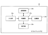
- FIG. 3 is a block diagram showing an internal configuration of a client PC in the endoscopy department system shown in FIG.
- each of the client PC 22 is composed of an input unit 22a, a display unit 22b, a recording unit 22c, a transmission / reception unit 22d, and a control unit 22e.
- the input unit 22a is an input means for performing various inputs, and is composed of an input device such as a keyboard and a touch panel, and a pointing device such as a mouse and a trackball.
- the display unit 22b is a display for displaying various images, reports, and the like, and is composed of an LCD (Liquid Crystal Display), a CRT (Cathode Ray Tube), and the like.
- LCD Liquid Crystal Display
- CRT Cathode Ray Tube
- the recording unit 22c is composed of a hard disk or the like for recording various data.
- the transmission / reception unit 22d is composed of a transmission / reception interface circuit and the like, and executes a process of transmitting / receiving various instructions, various requests, and various data via the intra-department LAN 27.
- the control unit 22e includes various processors that execute programs to perform processing, a RAM (Random Access Memory), and a ROM (Read Only Memory).
- a RAM Random Access Memory
- ROM Read Only Memory
- programmable logic which is a processor whose circuit configuration can be changed after manufacturing
- CPU Central Processing Unit
- FPGA Field Programmable Gate Array
- a dedicated electric circuit or the like which is a processor having a circuit configuration specially designed for executing a specific process such as a device (Programmable Logic Device: PLD) or an ASIC (Application Specific Integrated Circuit), is included.
- the structure of these various processors is an electric circuit that combines circuit elements such as semiconductor elements.
- the control unit 22e may be composed of one of various processors, or may be composed of a combination of two or more processors of the same type or different types (for example, a combination of a plurality of FPGAs or a combination of a CPU and an FPGA). You may.
- the control unit 22e controls each unit of the client PC 22 according to the above program, various requests transmitted from the outside via the intra-department LAN 27, instruction information input from the input unit 22a, and the like.
- FIG. 4 is a diagram showing an example of the basic screen of the application of the client PC 22.
- the control unit 22e acquires the basic screen data from the database DB and displays the basic screen shown in FIG. 4 on the display unit 22b.
- the client PC 22 is, for example, the client PC 22 in the examination room 20C, but is not limited to this, and may be another client PC 22 shown in FIG.
- This basic screen is for area A that displays a list of inspection request information (partially excerpted information), area B that displays various operation buttons, and inspection request information selected in the list of area A. It is composed of an area C for displaying a valid launcher.
- processing items such as "visit”, “reception”, “inspection”, and “accounting” are provided for each inspection request information, and the processing indicated by each processing item for each inspection request information is completed. When this is done, a " ⁇ " mark is displayed for each processing item.
- the data for displaying this mark is registered in the database DB by the endoscopy department server 21 when each process is completed. For example, when the inspection based on the inspection request information is completed, the endoscope department server 21 registers the information indicating that the inspection is completed in the database DB in association with the inspection request information. As a result, a " ⁇ " mark is displayed in the processing item of "inspection". Information on whether or not each process has been completed may be manually input, or may be automatically notified from the client PC 22 or the endoscope device 24.
- This application has a “report” button C1 as an operation button, and the "report” button C1 is displayed in the area C of the basic screen shown in FIG.
- This button C1 is a button for creating a report for the inspection based on the inspection request information selected from the list of the area A.
- the control unit 22e of the client PC 22 periodically acquires data for displaying this basic screen from the database DB and displays it on the display unit 22b.
- a report creator for example, a report creator of a still image to be inserted into the report. It supports the choice of the doctor).
- FIG. 5 is a diagram showing an example of the endoscope device 24.
- the endoscope device 24 includes an endoscope 1, a control device 4 to which the endoscope 1 is connected, and a light source device 5.
- the control device 4 includes a display device 7 that displays an image captured by imaging the inside of the subject with the endoscope 1, and an input unit 6 that is an interface for inputting various information to the control device 4. And are connected.
- the control device 4 controls the endoscope 1, the light source device 5, and the display device 7.
- the display device 7 has a display surface in which display pixels are arranged in a two-dimensional manner, and pixel data constituting the image data is drawn on each display pixel of the display surface, so that an image based on the image data is drawn. Is displayed.
- the display device 7 constitutes a display unit that switches the display image in response to a command from the control device 4.
- the endoscope 1 is a tubular member extending in one direction and is provided at an insertion portion 110 inserted into a subject and a proximal end portion of the insertion portion 110. Observation mode switching operation, imaging recording operation, forceps operation, An operation unit 11 provided with an operation member for performing air supply / water supply operation, suction operation, etc., an angle knob 12 provided adjacent to the operation unit 11, an endoscope 1, a control device 4 and a light source device.
- forceps holes for inserting forceps for collecting biological tissues such as cells or polyps, channels for air supply and water supply, and channels for air supply and water supply.
- Various channels such as a suction channel are provided.
- the insertion portion 110 is composed of a flexible soft portion 10A, a curved portion 10B provided at the tip of the flexible portion 10A, and a hard tip portion 10C provided at the tip of the curved portion 10B.
- the curved portion 10B is configured to be bendable by rotating the angle knob 12.
- the curved portion 10B can be curved in an arbitrary direction and an arbitrary angle according to the part of the subject in which the endoscope 1 is used, and the tip portion 10C can be directed in a desired direction.
- FIG. 6 is a schematic view showing the internal configuration of the endoscope device 24 shown in FIG.
- FIG. 7 is a diagram showing an example of a spectrum of light generated by the light source device 5 shown in FIG.
- the light source device 5 can irradiate the illumination light by switching between normal light and special light.
- Normal light is light having an emission spectrum suitable for recognition by humans such as doctors, such as white light.
- the special light is light having an emission spectrum suitable for analysis by a computer such as IEE (Image-Enhanced Endoscopy: image-enhanced observation), which has an emission spectrum different from that of normal light.
- IEE Image-Enhanced Endoscopy: image-enhanced observation
- the light source device 5 includes a light source processor 151, a light source unit 152, and an optical path coupling unit 154.
- the light source processor 151 is connected to the system control unit 44 of the control device 4, and controls the light source unit 152 based on a command from the system control unit 44.
- the light source unit 152 has, for example, a plurality of semiconductor light sources, each of which is turned on or off, and when the light source unit 152 is turned on, the amount of light emitted from each semiconductor light source is controlled to emit illumination light that illuminates the observation target.
- the light source unit 152 includes a V-LED (Violet Light Emitting Diet) 152a, a B-LED (Blue Light Emitting Diode) 152b, a G-LED (Green Light Emitting Diode) 152c, and an R-LED (Red).
- Emitting Diet It has a four-color LED of 152d.
- the light source processor 151 independently controls V-LED152a, B-LED152b, G-LED152c, and R-LED152d to independently control purple light V, blue light B, green light G, or red light R, respectively. It is possible to emit light by changing the amount of light.
- the V-LED152a generates purple light V having a center wavelength of 405 ⁇ 10 nm and a wavelength range of 380 to 420 nm.
- the B-LED152b generates blue light B having a center wavelength of 450 ⁇ 10 nm and a wavelength range of 420 to 500 nm.
- the G-LED152c generates green light G having a wavelength range of 480 to 600 nm.
- the R-LED152d generates red light R having a center wavelength of 620 to 630 nm and a wavelength range of 600 to 650 nm.
- the light source processor 151 emits white light having a light amount ratio of Vc: Bc: Gc: Rc among purple light V, blue light B, green light G, and red light R when irradiated with normal light.
- each LED 152a to 52d is controlled.
- the light source processor 151 has a light amount ratio of Vs: Bs: Gs: Rs with purple light V, blue light B, green light G, and red light R as short-wavelength narrow-band light when irradiated with special light.
- the LEDs 152a to 52d are controlled so as to emit the special light.
- the light amount ratio Vs: Bs: Gs: Rs is different from the light amount ratio Vc: Bc: Gc: Rc used when irradiating normal light, and is appropriately determined according to the purpose of observation. For example, when emphasizing superficial blood vessels, it is preferable to make Vs larger than other Bs, Gs, Rs, and when emphasizing mesopelagic blood vessels, Gs is made larger than other Vs, Gs, Rs. It is also preferable to increase the size.
- the optical path coupling unit 154 combines the lights emitted from the V-LED152a, B-LED152b, G-LED152c, and R-LED152d, and emits the combined light as illumination light.
- the illumination light emitted from the optical path coupling portion 154 of the light source portion 152 enters the light guide 153 described later built in the universal cord 13, and passes through the illumination lens 150 provided at the tip portion 10C of the insertion portion 110. The subject is illuminated.
- the tip portion 10C of the endoscope 1 includes an imaging optical system including an objective lens 121 and a lens group 122, an imaging element 123 that images a subject through the imaging optical system, a memory 125 such as a RAM, and a communication interface (I). / F) 126, an image pickup driving unit 127, and a light guide 153 for guiding the illumination light emitted from the light source unit 152 to the illumination lens 150 are provided.
- the image sensor 123 constitutes the image pickup unit of the present invention.
- the light guide 153 extends from the tip portion 10C to the connector portion 13A of the universal cord 13. With the connector portion 13A of the universal cord 13 connected to the light source device 5, the illumination light emitted from the light source portion 152 of the light source device 5 can be incident on the light guide 153.
- the image sensor 123 As the image sensor 123, a CCD (Charge Coupled Device) image sensor, a CMOS (Complementary Metal Oxide Semiconductor) image sensor, or the like is used. In the present embodiment, the image sensor 123 is a CMOS that uses a rolling shutter.
- CCD Charge Coupled Device
- CMOS Complementary Metal Oxide Semiconductor
- the image sensor 123 has a light receiving surface in which a plurality of pixels are arranged two-dimensionally, and the optical image formed on the light receiving surface by the above imaging optical system is converted into an electric signal (imaging signal) in each pixel. do. Then, the image pickup device 123 converts the converted image pickup signal from an analog signal into a digital signal having a predetermined number of bits, and outputs the image pickup signal converted into the digital signal to the memory 125.
- the image pickup device 123 for example, one equipped with a color filter such as a primary color or a complementary color is used.
- the image sensor 123 may be arranged at the tip portion 10C in a state where the light receiving surface is perpendicular to the optical axis Ax of the objective lens 121, or the light receiving surface is parallel to the optical axis Ax of the objective lens 121. It may be arranged in the tip portion 10C in such a state.
- the image pickup optical system provided in the endoscope 1 includes optical members (including the above lens group 122) such as a lens and a prism on the optical path of light from the subject between the image pickup element 123 and the objective lens 121. It is composed of an objective lens 121.
- the imaging optical system may be composed of only the objective lens 121.
- the memory 125 temporarily records the digital image pickup signal output from the image sensor 123.
- the communication I / F 126 is connected to the communication interface (I / F) 41 of the control device 4.
- the communication I / F 126 transmits the image pickup signal recorded in the memory 125 to the control device 4 through the signal line in the universal code 13.
- the image pickup drive unit 127 is connected to the system control unit 44 of the control device 4 via the communication I / F 126.
- the image pickup drive unit 127 drives the image pickup element 123 and the memory 125 based on a command from the system control unit 44 received by the communication I / F 126.
- the control device 4 includes a communication I / F 41 connected to the communication I / F 126 of the endoscope 1 by a universal code 13, a signal processing unit 42, a display controller 43, a system control unit 44, a recording medium 45, and the like. To be equipped.
- the communication I / F 41 receives the image pickup signal transmitted from the communication I / F 126 of the endoscope 1 and transmits it to the signal processing unit 42.
- the signal processing unit 42 has a built-in memory for temporarily recording the image pickup signal received from the communication I / F 41, and processes the image pickup image signal which is a set of the image pickup signals recorded in the memory (demosaic processing, gamma correction processing, etc.). Image processing) to generate captured image information in a format that can be recognized and processed.
- the captured image information generated by the signal processing unit 42 is recorded on a recording medium 45 such as a hard disk or a flash memory.
- the display controller 43 causes the display device 7 to display an captured image based on the captured image information generated by the signal processing unit 42.
- the coordinates of each pixel data constituting the captured image information generated by the signal processing unit 42 are managed in association with the coordinates of any of the display pixels constituting the display surface of the display device 7.
- the system control unit 44 controls each part of the control device 4 and sends a command to the image pickup drive unit 127 of the endoscope 1 and the light source processor 151 of the light source device 5 to control the entire endoscope device 24 in an integrated manner. do.
- the system control unit 44 controls the image pickup device 123 via the image pickup drive unit 127.
- the system control unit 44 controls the light source unit 152 via the light source processor 151.
- the system control unit 44 and the signal processing unit 42 include various processors that execute programs to perform processing, RAM, and ROM.
- a CPU As various processors, a CPU, a general-purpose processor that executes a program to perform various processes, a programmable logic device that is a processor whose circuit configuration can be changed after manufacturing such as FPGA, or a specific process such as an ASIC is executed.
- a dedicated electric circuit or the like which is a processor having a circuit configuration specially designed for the purpose of using the CPU, is included.
- the structure of these various processors is an electric circuit that combines circuit elements such as semiconductor elements.
- the system control unit 44 and the signal processing unit 42 may be composed of one of various processors, or a combination of two or more processors of the same type or different types (for example, a combination of a plurality of FPGAs or a CPU and an FPGA). It may be composed of a combination of).
- the endoscope device 24 periodically switches the emission spectrum of the illumination light during continuous shooting by the endoscope device 24.
- the endoscope device 24 switches the illumination light to normal light such as white light for 9 frames and the illumination light to special light such as narrow band light for 1 frame immediately after that. Is performed periodically.
- the frame referred to here is a photographing frame by the endoscope device 24.
- the ratio of the time of normal light to the time of special light in each cycle is not limited to 1: 9 and can be set arbitrarily.
- the captured image data obtained by continuous photographing by the endoscope device 24 includes the photographed image data obtained by photographing with normal light (photographed image data with normal light) and the photographed image data obtained by photographing with special light.
- the captured image data (photographed image data of special light) and the captured image data are included.
- the endoscope device 24 displays, for example, an image of normal light based on captured image data of normal light and an image of special light based on captured image data of special light on the display device 7.
- the endoscope device 24 may set the image of the special light based on the captured image data of the special light as a processing target such as analysis without displaying it by the display device 7 (that is, in the background).
- the endoscope device 24 inputs at least one of the photographed image data of normal light and the photographed image data of special light among the photographed image data obtained by continuous photographing to the image processing device 23.
- the image processing device 23 may detect singular findings based on the captured image data of normal light among the captured image data continuously input from the endoscope device 24, or the captured image data of special light.
- the peculiar findings may be detected based on the above, or the peculiar findings may be detected based on both captured image data.
- the image processing device 23 detects a peculiar finding based on, for example, captured image data of normal light, it generates a second still image of normal light based on the captured image data.
- the image processing device 23 detects a peculiar finding based on the captured image data of the special light, it generates a second still image of the special light based on the captured image data.
- the second still image of the special light based on the captured image data of the special light and the normal image based on the captured image data of the normal light are used. Both a second still image of light and may be generated.
- the captured image data of the normal light is, for example, the captured image data of the special light in which the peculiar findings are detected among the captured image data of the normal light input from the endoscope device 24 to the image processing device 23. It is the captured image data having the shooting time closest to the time.
- the switching of the illumination light is not limited to this. That is, the endoscope device 24 may periodically switch the illumination light to two or more illumination lights having different emission spectra. For example, the endoscope device 24 may periodically switch between normal light, first special light, and second special light having a different emission spectrum from the first special light.
- the image processing device 23 detects a peculiar finding based on the captured image data of an arbitrary emission spectrum among the captured image data continuously input from the endoscope device 24.
- FIG. 8 is a diagram showing an example of accumulation of the first still image and the second still image.
- the horizontal axis represents time.
- a doctor finds a peculiar finding while looking at a live image displayed on a display of the endoscope device 24 (for example, the display device 7 of FIG. 5) during a diagnosis using the endoscope device 24.
- a still image acquisition operation is performed on the endoscope device 24 at an arbitrary timing.
- the first still image is generated in the endoscope device 24.
- manually acquired images 51 and 52 are generated as the first still image.
- the manually acquired images 51 and 52 are stored in the medical image storage system 40 together with time information indicating the time when the manually acquired images 51 and 52 are generated, respectively.
- the image processing device 23 detects a peculiar finding (for example, a lesion such as a malignant tumor) by analysis by AI based on the photographed image data continuously input from the endoscope device 24. ..
- This analysis by AI is, for example, a back-end AI analysis performed in a state invisible to a doctor or the like (at the back end).
- the image processing device 23 calculates an index value of mucosal information by AI from the photographed image data obtained by imaging the observation target with the endoscope device 24.
- the index value is, for example, a value indicating at least one of the blood vessels, ducts, redness, folds, and mucus of the observation target represented by the image signal. Then, the image processing apparatus 23 determines whether or not the mucosal information (mucosal state) to be observed corresponds to a lesion such as a malignant tumor based on the calculated index value, thereby determining a lesion such as a malignant tumor (a lesion such as a malignant tumor). Specific findings) are detected.
- the image processing device 23 generates a second still image based on the captured image data when a peculiar finding is detected by back-end AI analysis among the captured image data continuously input from the endoscope device 24.
- automatically acquired images 53 to 57 are generated as the second still image.
- the automatically acquired images 53 to 57 are stored in the medical image storage system 40 together with time information indicating the time when the automatically acquired images 53 to 57 are generated, respectively.
- FIG. 9 is a diagram showing an example of an image selection screen of the client PC 22.
- the "screen display" button C2 included in the area C of the basic screen is instructed after the first still image and the second still image are stored in the medical image storage system 40 by the diagnosis using the endoscope device 24, Areas D to F are displayed in place of the areas A and B shown in FIG.
- operation units such as buttons for performing various operations on the areas D and E are arranged.
- the first still image (manually acquired image) and the second still image (automatically acquired image) generated for the target patient are generated.
- the control unit 22e of the client PC 22 displays these still images by acquiring them from the medical image storage system 40.
- the first still images generated for the target patient are displayed side by side.
- four first still images are displayed in the area D.
- more first still images may be able to be displayed in the area D by scrolling the screen or the like.
- the thick frame D1 is displayed so as to surround the selected first still image among the first still images displayed in the area D.
- the first still image on the upper left is selected.
- the selected first still image among the first still images displayed in the area D is switched, and the thick frame D1 also moves accordingly.
- the area E is an automatically acquired image having a shooting time that satisfies a predetermined condition with the shooting time of the first still image selected in the area D among the second still images generated for the target patient. Is displayed side by side as a third still image.
- the control unit 22e has a second still image having time information in which the magnitude of the difference from the time information of the selected first still image is equal to or less than a threshold value (constant value) from the second still images. Is extracted, and the extracted second still image is displayed side by side in the area E as a third still image.
- the threshold value is, for example, a value in the range of several seconds to several tens of seconds, but is not limited to a value in this range. In the example shown in FIG. 9, five second still images are displayed in the area E as the third still image.
- the control unit 22e causes the display unit 22b to display the first still image and the third still image in association with each other.
- Displaying the first still image and the third still image in association with each other means displaying the first still image and the third still image in a contrastable manner. For example, as shown in FIG. 9, the first still image is displayed. The image and the third still image are simultaneously displayed in different regions of the display unit 22b.
- the report creator can select a key image from the first still image and the third still image displayed in association with each other by operating the operation unit in the area F.
- a key image is one or more still images that are inserted into the report.
- the report creator can select a key image from one first still image in the upper left of the area D and five third still images in the area E.
- the selected key image constitutes a selected still image selected by the user from the first still image and the third still image, and is a candidate image of an image to be inserted into the inspection report by the endoscope device 24. Become.
- first still image and third still image are each still image whose shooting time is close to each other.
- the report creator can select either the manually acquired first still image or the third still image automatically acquired at the same time as the first still image as the key image. can. Therefore, for example, when the quality of the first still image is poor (for example, the blurring is large), an image having good quality can be selected and replaced from the third still image.
- the control unit 22e moves from the second still image to the upper right.
- the second still image having the time information whose difference from the time information of the first still image is equal to or less than the threshold value is extracted, and the extracted second still image is displayed side by side in the area E as the third still image.
- the report creator can select a key image from the first still image and the third still image displayed in association with each other.
- the report creator also selects a key image from the first still image and the third still image for the other first still image in the area D. It may be possible to delete a part of the first still image in the area D by operating the operation unit in the area F.
- FIG. 10 is a diagram showing an example of an overlooked concern image display screen of the client PC 22.
- the control unit 22e causes the display unit 22b to display the area G instead of the areas D and E.
- the fourth still images extracted by the control unit 22e from the second still images are displayed side by side.
- the fourth still image is a second still image having a shooting time in which the above conditions are incompatible with the shooting times of all the first still images in the area D.
- the control unit 22e displays the area G instead of the areas D and E
- the difference between the second still image and the time information of all the first still images in the area D is large.
- a second still image having time information whose value is larger than the threshold value is extracted, and the extracted second still image is displayed side by side in the area G as a fourth still image.
- the fourth still image is the second still image obtained by automatic shooting based on the back-end AI analysis during the time period when the still image acquisition operation was not performed. Therefore, the fourth still image includes an image that may be overlooked at the time of examination by the endoscope device 24.
- the report creator can select a key image from the fourth still image displayed in the area G by operating the operation unit in the area F.
- the key image is selected from the automatically acquired fourth still image. It can be selected and interpolated.
- the operator of the endoscope device 24 can perform a still image acquisition operation by focusing only on a clear lesion or the like found by himself / herself.
- the control unit 22e may display a plurality of fourth still images side by side in chronological order together with time information.
- the control unit 22e may display the fourth still image together with the selected key image on the screen shown in FIG. 9 in chronological order.
- the report creation screen for performing the report creation work is displayed on the display unit 22b. Will be done.
- each still image selected as a key image by each operation described in FIG. 9 can be selected as an image to be inserted into the report.
- the report operator can easily create a report in which an appropriate key image selected from the first still image (manually acquired image) and the second still image (automatically acquired image) is inserted.
- the created report is saved in, for example, the database DB of the endoscopy department server 21.
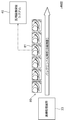
- FIG. 11 is a diagram showing an example of back-end AI analysis by the image processing device 23.
- the horizontal axis represents time.
- the captured image data group 80 is each captured image data continuously input from the endoscope device 24 to the image processing device 23.
- the image processing device 23 calculates the correct diagnosis rate based on the target captured image data for each of the captured image data included in the captured image data group 80.
- the correct diagnosis rate is the probability that a correct diagnosis will be made based on a still image based on captured image data.
- the correct diagnosis rate based on the captured image data can be performed using, for example, an AI model trained by a large number of samples of a combination of the captured image data and the correct diagnosis rate.
- the image processing device 23 receives the continuous captured image data when a certain number (6 frames as an example) of captured image data in which the calculated correct diagnosis rate is equal to or higher than the threshold value (90% as an example) is continuous. Generate a second still image based on at least a portion. In the example shown in FIG. 11, the image processing device 23 generates the second still image based on the captured image data 81 in the captured image data group 80. Then, the image processing device 23 stores the generated second still image in the medical image storage system 40 via the endoscopy department server 21.
- FIG. 12 is a sequence diagram showing an example of normal light photography based on automatic acquisition during special light observation.
- the endoscope device 24 sets the illumination light by the light source unit 152 to special light (step S1).
- the endoscope device 24 starts continuous shooting by the image sensor 123, and starts inputting the continuous shot image data obtained by the continuous shooting to the image processing device 23 (step S2).
- This captured image data is captured image data obtained by photographing in a state of being irradiated with special light.
- the image processing device 23 starts the above-mentioned back-end AI analysis based on the captured image data from the endoscope device 24 (step S3).
- the image processing device 23 detects a peculiar finding based on the captured image data from the endoscope device 24 (step S4).
- the image processing device 23 stops the back-end AI analysis (step S5) and generates a still image (special light) based on the captured image data in which the peculiar finding is detected (step S6).
- the image processing device 23 transmits a detection signal indicating that a peculiar finding has been detected to the endoscope device 24 (step S7).
- the endoscope device 24 sets the illumination light by the light source unit 152 to normal light (for example, white light) (step S8).
- the endoscope device 24 inputs the captured image data obtained by photographing by the image pickup element 123 into the image processing device 23 (step S9).
- This captured image data is captured image data obtained by photographing in a state of being irradiated with normal light.
- the image processing device 23 generates a still image (normal light) based on the captured image data input from the endoscope device 24 (step S10).
- the endoscope device 24 sets the illumination light by the light source unit 152 to special light (step S11).
- the endoscope device 24 restarts the continuous shooting by the image sensor 123, and starts inputting the continuous shot image data obtained by the continuous shooting to the image processing device 23 (step S12).
- This captured image data is captured image data obtained by photographing in a state of being irradiated with special light.
- the image processing device 23 restarts the above-mentioned back-end AI analysis based on the captured image data from the endoscope device 24 (step S13). After that, when the peculiar finding is detected again in the image processing apparatus 23, steps S5 to S12 are repeated.
- the image processing device 23 stores the still image of normal light generated in step S10 in the medical image storage system 40 as the second still image described above.
- a still image of the normal light at almost the same timing as when the special light is shot can be obtained. Therefore, a still image of the special light and a still image of the normal light for the same scene can be obtained. Can be done.
- the operator of the endoscope device 24 can focus on examination and diagnosis without considering the recording of reports and still images.
- the endoscope device 24 transmits the captured image data of the normal light to the image processing device 23, and the image processing device 23 transmits the captured image data of the normal light based on the captured image data.
- the process of generating a still image has been described, the process is not limited to such a process.
- the endoscope device 24 may generate a still image of the normal light based on the captured image data of the normal light, and transmit the generated still image of the normal light to the image processing device 23.
- the process of stopping the back-end AI analysis when the image processing device 23 detects a peculiar finding based on the captured image data has been described, but the image processing device 23 performs the back-end AI analysis when the peculiar finding is detected. You may continue.
- the back-end AI analysis is not limited to this, and various analyzes capable of detecting peculiar findings can be used.
- the analysis using AI has been described as the analysis for automatically acquiring the still image, the analysis for automatically acquiring the still image may be performed based on a specific algorithm that does not use AI. good.
- first still image and the second still image are stored in the medical image storage system 40
- the first still image and the second still image are processed by the endoscopy department server 21, the client PC 22, or the image processing. It may be configured to be stored in the device 23 or the like.
- the first still image and the third still image are simultaneously displayed in different regions of the display unit 22b.
- the control unit 22e of the client PC 22 compares the first still image with the third still image by displaying the first still image and the third still image on the display unit 22b while switching the time. It may be displayed as possible.
- An image selection support device that has a processor and a memory and supports selection of a still image based on captured image data obtained by an endoscope.
- the above memory From the first still image acquired based on the captured image data when the operator of the endoscope has acquired the still image, and from the captured image data when the acquisition operation is different from that of the first still image.
- One or more acquired second still images and are recorded,
- the above processor From the one or more second still images, a third still image having a shooting time satisfying a predetermined condition with the shooting time of the first still image is extracted.
- the first still image and the third still image are associated with each other.
- Image selection support device From the one or more second still images, a third still image having a shooting time satisfying a predetermined condition with the shooting time of the first still image is extracted.
- the first still image and the third still image are associated with each other.
- the image selection support device according to any one of (2) to (5).
- the processor selects a still image selected by the user from the first still image and the third still image displayed on the display in association with each other as the selected still image.
- Image selection support device selects a still image selected by the user from the first still image and the third still image displayed on the display in association with each other as the selected still image.
- the image selection support device according to any one of (2) to (6).
- the above processor From the one or more second still images, a fourth still image having a shooting time in which the above conditions are incompatible with the shooting time of the first still image is extracted.
- the fourth still image is displayed on the display, From the fourth still image, a still image that has been selected by the user is selected as the selected still image.
- Image selection support device From the fourth still image, a still image that has been selected by the user is selected as the selected still image.
- the image selection support device according to (6) or (7).
- the selected still image is a candidate image of an image to be inserted into the report of the endoscopic examination.
- Image selection support device .
- the image selection support device according to any one of (1) to (8).
- the second still image is a still image acquired from the captured image data in response to detection of a peculiar finding based on the analysis of the captured image data.
- Image selection support device .
- the analysis includes calculation of the correct diagnosis rate, which is the probability that a correct diagnosis is made by the second still image based on the captured image data.
- the second still image is a still image acquired from the captured image data when the calculated correct diagnosis rate is a certain value or more and the captured image data is continuously obtained in a certain number or more.
- Image selection support device is a still image acquired from the captured image data when the calculated correct diagnosis rate is a certain value or more and the captured image data is continuously obtained in a certain number or more.
- the image selection support device according to (9) or (10).
- the analysis is performed by an analysis device that receives the captured image data from the endoscope.
- the second still image is a still image acquired from the captured image data by the analysis device.
- Image selection support device is
- the image selection support device according to any one of (9) to (11).
- the second still image is a captured image obtained by the endoscope in a state where the emission spectrum of the illumination light taken by the endoscope is switched according to the detection of the peculiar finding based on the analysis of the captured image data. Including still images obtained from the data, Image selection support device.
- the image selection support device according to the above.
- the second still image is a state in which the emission spectrum of the illumination light taken by the endoscope is switched between the still image acquired from the captured image data in which the peculiar finding is detected and the illumination light taken by the endoscope in response to the detection of the peculiar finding. Including a still image acquired from the captured image data obtained by the above endoscope. Image selection support device.
- the image selection support device according to any one of (1) to (13).
- the processor extracts the third still image having a shooting time in which the difference from the shooting time of the first still image is equal to or less than a certain value from the one or more second still images.
- Image selection support device extracts the third still image having a shooting time in which the difference from the shooting time of the first still image is equal to or less than a certain value from the one or more second still images.
- the image selection support device according to any one of (1) to (14).
- the processor extracts the third still image from the acquired first still images with respect to the first still image selected by the user.
- Image selection support device
- An image selection support program that supports the selection of still images based on captured image data obtained by an endoscope. From the first still image acquired based on the captured image data when the operator of the endoscope has acquired the still image, and from the captured image data when the acquisition operation is different from that of the first still image. With one or more acquired second still images, From the one or more second still images, a third still image having a shooting time satisfying a predetermined condition with the shooting time of the first still image is extracted. The first still image and the third still image are associated with each other.
- An image selection support program that allows a computer to perform processing.
- Endoscope 4 Control device 5 Light source device 6, 22a Input unit 7 Display device 10 HIS 10A Flexible part 10B Curved part 10C Tip part 11 Operation part 12 Angle knob 13 Universal cord 13A Connector part 13B Connector part 20 Endoscope department system 20A Reception 20B Pretreatment room 20C Examination room 20D Cleaning room 20E Conference room 21 Endoscope department Server 22 Client PC 22b Display unit 22c Recording unit 22d Transmission / reception unit 22e Control unit 23 Image processing device 24 Endoscope device 25 Cleaning machine 27 In-department LAN 30 Pathology Department System 40 Medical Image Storage System 41,126 Communication I / F 42 Signal processing unit 43 Display controller 44 System control unit 45 Recording medium 50 Other department system 51, 52 Manual acquisition image 53-57 Automatic acquisition image 60 In-hospital LAN 80 Photographed image data group 81 Photographed image data 110 Insertion unit 121 Objective lens 122 Lens group 123 Imaging element 125 Memory 127 Imaging drive unit 150 Illumination lens 151 Light source processor 152 Light source unit 152a V-LED 152
Landscapes
- Engineering & Computer Science (AREA)
- Health & Medical Sciences (AREA)
- General Health & Medical Sciences (AREA)
- Medical Informatics (AREA)
- Theoretical Computer Science (AREA)
- Public Health (AREA)
- Nuclear Medicine, Radiotherapy & Molecular Imaging (AREA)
- Radiology & Medical Imaging (AREA)
- Physics & Mathematics (AREA)
- Primary Health Care (AREA)
- Epidemiology (AREA)
- General Engineering & Computer Science (AREA)
- General Physics & Mathematics (AREA)
- Life Sciences & Earth Sciences (AREA)
- Surgery (AREA)
- Human Computer Interaction (AREA)
- Quality & Reliability (AREA)
- Computer Vision & Pattern Recognition (AREA)
- Veterinary Medicine (AREA)
- Animal Behavior & Ethology (AREA)
- Molecular Biology (AREA)
- Heart & Thoracic Surgery (AREA)
- Biomedical Technology (AREA)
- Pathology (AREA)
- Optics & Photonics (AREA)
- Biophysics (AREA)
- Endoscopes (AREA)
Priority Applications (3)
| Application Number | Priority Date | Filing Date | Title |
|---|---|---|---|
| JP2022505008A JP7427766B2 (ja) | 2020-03-03 | 2021-01-13 | 画像選択支援装置、画像選択支援方法、及び画像選択支援プログラム |
| CN202180018819.9A CN115279249B (zh) | 2020-03-03 | 2021-01-13 | 图像选择辅助装置、图像选择辅助方法及记录介质 |
| US17/823,852 US12327353B2 (en) | 2020-03-03 | 2022-08-31 | Image selection support device, image selection support method, and image selection support program |
Applications Claiming Priority (2)
| Application Number | Priority Date | Filing Date | Title |
|---|---|---|---|
| JP2020-036270 | 2020-03-03 | ||
| JP2020036270 | 2020-03-03 |
Related Child Applications (1)
| Application Number | Title | Priority Date | Filing Date |
|---|---|---|---|
| US17/823,852 Continuation US12327353B2 (en) | 2020-03-03 | 2022-08-31 | Image selection support device, image selection support method, and image selection support program |
Publications (1)
| Publication Number | Publication Date |
|---|---|
| WO2021176852A1 true WO2021176852A1 (ja) | 2021-09-10 |
Family
ID=77613670
Family Applications (1)
| Application Number | Title | Priority Date | Filing Date |
|---|---|---|---|
| PCT/JP2021/000926 Ceased WO2021176852A1 (ja) | 2020-03-03 | 2021-01-13 | 画像選択支援装置、画像選択支援方法、及び画像選択支援プログラム |
Country Status (4)
| Country | Link |
|---|---|
| US (1) | US12327353B2 (https=) |
| JP (1) | JP7427766B2 (https=) |
| CN (1) | CN115279249B (https=) |
| WO (1) | WO2021176852A1 (https=) |
Families Citing this family (1)
| Publication number | Priority date | Publication date | Assignee | Title |
|---|---|---|---|---|
| JP7546270B2 (ja) * | 2020-09-23 | 2024-09-06 | 株式会社Aiメディカルサービス | 検査支援装置、検査支援方法および検査支援プログラム |
Citations (8)
| Publication number | Priority date | Publication date | Assignee | Title |
|---|---|---|---|---|
| JPH10323326A (ja) * | 1997-05-23 | 1998-12-08 | Olympus Optical Co Ltd | 内視鏡装置 |
| JP2008062069A (ja) * | 2007-09-13 | 2008-03-21 | Olympus Corp | 画像表示装置、画像表示方法および画像表示プログラム |
| JP2013230319A (ja) * | 2012-05-02 | 2013-11-14 | Olympus Corp | 内視鏡装置及び内視鏡装置の制御方法 |
| JP2014018471A (ja) * | 2012-07-19 | 2014-02-03 | Hoya Corp | 内視鏡の画像処理装置 |
| WO2016084779A1 (ja) * | 2014-11-27 | 2016-06-02 | オリンパス株式会社 | 画像再生装置および画像再生プログラム |
| WO2018216618A1 (ja) * | 2017-05-25 | 2018-11-29 | 日本電気株式会社 | 情報処理装置、制御方法、及びプログラム |
| WO2019039259A1 (ja) * | 2017-08-25 | 2019-02-28 | 富士フイルム株式会社 | 診断支援システム、内視鏡システム、プロセッサ、及び診断支援方法 |
| WO2019130964A1 (ja) * | 2017-12-28 | 2019-07-04 | 富士フイルム株式会社 | 内視鏡画像取得システム及び方法 |
Family Cites Families (2)
| Publication number | Priority date | Publication date | Assignee | Title |
|---|---|---|---|---|
| JP6243311B2 (ja) | 2014-09-30 | 2017-12-06 | 富士フイルム株式会社 | 内視鏡用のプロセッサ装置、内視鏡用のプロセッサ装置の作動方法、内視鏡用の制御プログラム |
| WO2018043585A1 (ja) * | 2016-08-31 | 2018-03-08 | Hoya株式会社 | 内視鏡装置、情報処理装置およびプログラム |
-
2021
- 2021-01-13 WO PCT/JP2021/000926 patent/WO2021176852A1/ja not_active Ceased
- 2021-01-13 CN CN202180018819.9A patent/CN115279249B/zh active Active
- 2021-01-13 JP JP2022505008A patent/JP7427766B2/ja active Active
-
2022
- 2022-08-31 US US17/823,852 patent/US12327353B2/en active Active
Patent Citations (8)
| Publication number | Priority date | Publication date | Assignee | Title |
|---|---|---|---|---|
| JPH10323326A (ja) * | 1997-05-23 | 1998-12-08 | Olympus Optical Co Ltd | 内視鏡装置 |
| JP2008062069A (ja) * | 2007-09-13 | 2008-03-21 | Olympus Corp | 画像表示装置、画像表示方法および画像表示プログラム |
| JP2013230319A (ja) * | 2012-05-02 | 2013-11-14 | Olympus Corp | 内視鏡装置及び内視鏡装置の制御方法 |
| JP2014018471A (ja) * | 2012-07-19 | 2014-02-03 | Hoya Corp | 内視鏡の画像処理装置 |
| WO2016084779A1 (ja) * | 2014-11-27 | 2016-06-02 | オリンパス株式会社 | 画像再生装置および画像再生プログラム |
| WO2018216618A1 (ja) * | 2017-05-25 | 2018-11-29 | 日本電気株式会社 | 情報処理装置、制御方法、及びプログラム |
| WO2019039259A1 (ja) * | 2017-08-25 | 2019-02-28 | 富士フイルム株式会社 | 診断支援システム、内視鏡システム、プロセッサ、及び診断支援方法 |
| WO2019130964A1 (ja) * | 2017-12-28 | 2019-07-04 | 富士フイルム株式会社 | 内視鏡画像取得システム及び方法 |
Also Published As
| Publication number | Publication date |
|---|---|
| US20220414873A1 (en) | 2022-12-29 |
| JPWO2021176852A1 (https=) | 2021-09-10 |
| CN115279249A (zh) | 2022-11-01 |
| JP7427766B2 (ja) | 2024-02-05 |
| US12327353B2 (en) | 2025-06-10 |
| CN115279249B (zh) | 2025-01-10 |
Similar Documents
| Publication | Publication Date | Title |
|---|---|---|
| JP7346285B2 (ja) | 医療画像処理装置、内視鏡システム、医療画像処理装置の作動方法及びプログラム | |
| JP7326308B2 (ja) | 医療画像処理装置及び医療画像処理装置の作動方法、内視鏡システム、プロセッサ装置、診断支援装置並びにプログラム | |
| US20180153385A1 (en) | Displaying image data from a scanner capsule | |
| JP6889282B2 (ja) | 医療画像処理装置及び方法、内視鏡システム、プロセッサ装置、診断支援装置並びにプログラム | |
| EP4091532B1 (en) | Medical image processing device, endoscope system, diagnosis assistance method, and program | |
| US12458207B2 (en) | Endoscopic examination support device, endoscopic examination support method, and endoscopic examination support program | |
| US11423318B2 (en) | System and methods for aggregating features in video frames to improve accuracy of AI detection algorithms | |
| US20090023993A1 (en) | System and method for combined display of medical devices | |
| CN112512398B (zh) | 医疗图像处理装置 | |
| CN112105286A (zh) | 内窥镜装置、内窥镜操作方法及程序 | |
| WO2019039252A1 (ja) | 医療画像処理装置及び医療画像処理方法 | |
| JPWO2020184257A1 (ja) | 医用画像処理装置及び方法 | |
| US20230222666A1 (en) | Medical image processing apparatus, method for operating medical image processing apparatus, and non-transitory computer readable medium | |
| JP7775047B2 (ja) | 内視鏡システム、医療画像処理装置及びその作動方法 | |
| CN112584746B (zh) | 医用图像处理装置和内窥镜系统 | |
| WO2014061554A1 (ja) | 画像処理装置及び画像処理方法 | |
| JP7427766B2 (ja) | 画像選択支援装置、画像選択支援方法、及び画像選択支援プログラム | |
| JP7679453B2 (ja) | 医療支援システムおよび医療支援方法 | |
| WO2023175916A1 (ja) | 医療支援システムおよび画像表示方法 | |
| JP2024112325A (ja) | 医療画像処理装置、内視鏡システム、及び医療画像処理装置の作動方法 | |
| WO2025027838A1 (ja) | 医療支援装置、医療支援システムおよび医療支援方法 | |
| US20240233896A9 (en) | Information processing apparatus, information processing method, endoscope system, and report creation support device | |
| US20240108198A1 (en) | Medical image processing device, endoscope system, and operation method of medical image processing device | |
| WO2023166647A1 (ja) | 医療支援システムおよび画像表示方法 |
Legal Events
| Date | Code | Title | Description |
|---|---|---|---|
| 121 | Ep: the epo has been informed by wipo that ep was designated in this application |
Ref document number: 21764526 Country of ref document: EP Kind code of ref document: A1 |
|
| ENP | Entry into the national phase |
Ref document number: 2022505008 Country of ref document: JP Kind code of ref document: A |
|
| NENP | Non-entry into the national phase |
Ref country code: DE |
|
| 122 | Ep: pct application non-entry in european phase |
Ref document number: 21764526 Country of ref document: EP Kind code of ref document: A1 |
|
| WWG | Wipo information: grant in national office |
Ref document number: 202180018819.9 Country of ref document: CN |