WO2021171878A1 - 面状照明装置 - Google Patents
面状照明装置 Download PDFInfo
- Publication number
- WO2021171878A1 WO2021171878A1 PCT/JP2021/002725 JP2021002725W WO2021171878A1 WO 2021171878 A1 WO2021171878 A1 WO 2021171878A1 JP 2021002725 W JP2021002725 W JP 2021002725W WO 2021171878 A1 WO2021171878 A1 WO 2021171878A1
- Authority
- WO
- WIPO (PCT)
- Prior art keywords
- emitting surface
- light
- light emitting
- row
- light source
- Prior art date
- Legal status (The legal status is an assumption and is not a legal conclusion. Google has not performed a legal analysis and makes no representation as to the accuracy of the status listed.)
- Ceased
Links
Images


Classifications
-
- F—MECHANICAL ENGINEERING; LIGHTING; HEATING; WEAPONS; BLASTING
- F21—LIGHTING
- F21S—NON-PORTABLE LIGHTING DEVICES; SYSTEMS THEREOF; VEHICLE LIGHTING DEVICES SPECIALLY ADAPTED FOR VEHICLE EXTERIORS
- F21S2/00—Systems of lighting devices, not provided for in main groups F21S4/00 - F21S10/00 or F21S19/00, e.g. of modular construction
-
- F—MECHANICAL ENGINEERING; LIGHTING; HEATING; WEAPONS; BLASTING
- F21—LIGHTING
- F21V—FUNCTIONAL FEATURES OR DETAILS OF LIGHTING DEVICES OR SYSTEMS THEREOF; STRUCTURAL COMBINATIONS OF LIGHTING DEVICES WITH OTHER ARTICLES, NOT OTHERWISE PROVIDED FOR
- F21V7/00—Reflectors for light sources
-
- F—MECHANICAL ENGINEERING; LIGHTING; HEATING; WEAPONS; BLASTING
- F21—LIGHTING
- F21V—FUNCTIONAL FEATURES OR DETAILS OF LIGHTING DEVICES OR SYSTEMS THEREOF; STRUCTURAL COMBINATIONS OF LIGHTING DEVICES WITH OTHER ARTICLES, NOT OTHERWISE PROVIDED FOR
- F21V7/00—Reflectors for light sources
- F21V7/04—Optical design
- F21V7/09—Optical design with a combination of different curvatures
-
- G—PHYSICS
- G02—OPTICS
- G02F—OPTICAL DEVICES OR ARRANGEMENTS FOR THE CONTROL OF LIGHT BY MODIFICATION OF THE OPTICAL PROPERTIES OF THE MEDIA OF THE ELEMENTS INVOLVED THEREIN; NON-LINEAR OPTICS; FREQUENCY-CHANGING OF LIGHT; OPTICAL LOGIC ELEMENTS; OPTICAL ANALOGUE/DIGITAL CONVERTERS
- G02F1/00—Devices or arrangements for the control of the intensity, colour, phase, polarisation or direction of light arriving from an independent light source, e.g. switching, gating or modulating; Non-linear optics
- G02F1/01—Devices or arrangements for the control of the intensity, colour, phase, polarisation or direction of light arriving from an independent light source, e.g. switching, gating or modulating; Non-linear optics for the control of the intensity, phase, polarisation or colour
- G02F1/13—Devices or arrangements for the control of the intensity, colour, phase, polarisation or direction of light arriving from an independent light source, e.g. switching, gating or modulating; Non-linear optics for the control of the intensity, phase, polarisation or colour based on liquid crystals, e.g. single liquid crystal display cells
- G02F1/133—Constructional arrangements; Operation of liquid crystal cells; Circuit arrangements
- G02F1/1333—Constructional arrangements; Manufacturing methods
- G02F1/1335—Structural association of cells with optical devices, e.g. polarisers or reflectors
- G02F1/1336—Illuminating devices
-
- F—MECHANICAL ENGINEERING; LIGHTING; HEATING; WEAPONS; BLASTING
- F21—LIGHTING
- F21Y—INDEXING SCHEME ASSOCIATED WITH SUBCLASSES F21K, F21L, F21S and F21V, RELATING TO THE FORM OR THE KIND OF THE LIGHT SOURCES OR OF THE COLOUR OF THE LIGHT EMITTED
- F21Y2105/00—Planar light sources
- F21Y2105/10—Planar light sources comprising a two-dimensional [2D] array of point-like light-generating elements
- F21Y2105/14—Planar light sources comprising a two-dimensional [2D] array of point-like light-generating elements characterised by the overall shape of the two-dimensional [2D] array
- F21Y2105/18—Planar light sources comprising a two-dimensional [2D] array of point-like light-generating elements characterised by the overall shape of the two-dimensional [2D] array annular; polygonal other than square or rectangular, e.g. for spotlights or for generating an axially symmetrical light beam
-
- F—MECHANICAL ENGINEERING; LIGHTING; HEATING; WEAPONS; BLASTING
- F21—LIGHTING
- F21Y—INDEXING SCHEME ASSOCIATED WITH SUBCLASSES F21K, F21L, F21S and F21V, RELATING TO THE FORM OR THE KIND OF THE LIGHT SOURCES OR OF THE COLOUR OF THE LIGHT EMITTED
- F21Y2115/00—Light-generating elements of semiconductor light sources
- F21Y2115/10—Light-emitting diodes [LED]
Definitions
- the present invention relates to a planar lighting device.
- a planar lighting device used for the backlight of a liquid crystal display device a plurality of light sources such as LEDs (Light Emitting Diodes) are arranged two-dimensionally, and an optical sheet or the like is arranged on the light emitting surface side, so-called.
- a direct type planar lighting device is known.
- the light emitting surface of the planar lighting device is rectangular, the light sources are generally arranged at equal pitches in the horizontal direction and the vertical direction of the light emitting surface.
- planar lighting devices have a rectangular outer shape, but a circular device other than the rectangular one has been proposed depending on the place where the lighting device is mounted (see, for example, Patent Document 1 and the like). ..
- a planar illuminator having, for example, a circular light emitting surface other than a rectangular shape
- a general arrangement of light sources that is easy to design and manufacture that is, an arrangement of light sources at equal pitches in the horizontal and vertical directions of the light emitting surface.
- the present invention has been made in view of the above, and an object of the present invention is to improve the uniformity of brightness at an end portion of a planar illumination device having a light emitting surface having an outer shape other than a rectangle.
- the planar illumination device is a planar illumination device having a light emitting surface having an outer shape other than a rectangle.
- light sources are arranged at a predetermined pitch in one direction along the light emitting surface, and the first type row in which the light sources are housed in the light emitting surface and half of the pitch with respect to the row.
- the light sources are arranged at the predetermined pitch in the one direction, and the second type row in which the light sources are housed in the light emitting surface is arranged in a direction orthogonal to the one direction. Has been done.
- the planar illumination device can improve the uniformity of brightness at the end portion of the planar illumination device having a light emitting surface having an outer shape other than a rectangle.
- FIG. 1 is a plan view showing a configuration example of a planar lighting device according to an embodiment.
- FIG. 2 is a cross-sectional view taken along the line YY in FIG.
- FIG. 3 is a diagram showing an example of arrangement of a light source in a planar lighting device.
- FIG. 4 is a diagram showing an example of arrangement of light sources in the comparative example.
- FIG. 5 is a diagram showing an example of a luminance simulation result according to the embodiment of FIG.
- FIG. 6 is a diagram showing an example in which lighting / extinguishing is performed in units of regions extending in the horizontal direction by local dimming.
- planar illuminating device having a light emitting surface having an outer shape other than a rectangle a planar illuminating device having a light emitting surface having a circular outer shape will be described as an example. Anything that has an outer light emitting surface may be used. For example, it may have a light emitting surface having an elliptical outer shape, or may have a light emitting surface having a parallelogram outer shape.
- FIG. 1 is a plan view showing a configuration example of the planar lighting device 1 according to the embodiment, and is a view seen from the exit surface side.
- FIG. 2 is a cross-sectional view taken along the line YY in FIG.
- the outer shape of the light emitting surface of the planar illumination device 1 is circular, and rows L1 to L16 extend in the lateral direction (one direction along the light emitting surface) in the figure, and in the figure, the rows L1 to L16 extend. Rows L1 to L16 are arranged symmetrically in the downward direction (direction orthogonal to one direction) from the upper end.
- Each row L1 to L16 is a row in which light sources 3 are arranged at a predetermined pitch in one direction (horizontal direction in the figure) along the light emitting surface, and these light sources 3 are housed in the light emitting surface.
- L3, L5, L7 to L10, L12, L14, and the light source 3 is arranged in one direction at a predetermined pitch, shifted in the row direction by half the pitch (half pitch) with respect to these first type rows.
- These light sources 3 are divided into rows L1, L2, L4, L6, L11, L13, L15, and L16, which are the second type rows in which the light source 3 is housed in the light emitting surface.
- the first type row has no light source on the center line C extending in a direction orthogonal to one direction (horizontal direction in the figure) of the light emitting surface (the center line C is arranged between adjacent light sources), and the second type row. In the line of, the light source is arranged on the center line C.
- Whether it is a type 1 row or a type 2 row is determined according to the distance from the center line C to the end of the light emitting surface in one direction. More details will be described later.
- Each light source 3 is arranged on the substrate 2, and each light source 3 is arranged at the center of a plurality (many) reflecting portions provided on the reflector 4. Each reflecting portion is composed of four inclined reflecting surfaces 4a centered on the light source 3.
- the reflector 4 reflects light in a required direction, and can improve the brightness uniformity of the light emitting surface carried by each light source 3.
- the amount of light from each light source 3 is set to be constant.
- the positions (positions in the vertical direction and / or horizontal direction in the figure) of the light source 3 at the ends of the rows L1 to L16 are adjusted as necessary.
- the light sources 31 to 34 in FIG. 1 and the light sources at symmetrical positions in the vertical and horizontal directions are shifted from a predetermined pitch.
- the reflecting portions 41 to 46 in FIG. 1 and the reflecting portions located symmetrically with each other in the vertical and horizontal directions are different in shape from the others.
- the position of these light sources and the shape of the reflecting portion are adjusted according to the position of the end portion of the light emitting surface. Specifically, the brightness at the end is simulated to make adjustments so that the uniformity of the brightness is increased. Since adjustments are made only to the light source and the reflecting portion at the end of the light emitting surface, and most of the light sources and the reflecting portions can be made regular, the influence on the design and manufacturing can be small.
- planar lighting device 1 as a product, optical sheets such as a diffusion sheet and a brightness improving sheet are arranged on the exit surface side of the light emitting surface, and the entire planar illumination device 1 is provided with an opening on the exit surface. It is generally stored in a housing frame.
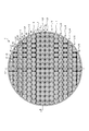
- FIG. 3 is a diagram showing an example of the arrangement of the light source 3 in the planar lighting device 1, and corresponds to the arrangement of the light source 3 in FIG.
- the small white squares in FIG. 3 indicate the light source 3.
- the scales on the vertical and horizontal axes indicate the distance from the center (unit is "mm").
- the solid circle indicates the effective area of the light emitting surface.
- the broken line circle indicates the arrangement range of the light source 3.
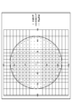
- FIG. 4 is a diagram showing an example of arrangement of the light source 3'in the comparative example, in which rows having the same pitch are arranged and only the position of the light source at the end is adjusted.
- the notation is the same as in FIG.
- the arrangement density around the light source 3'at the end portion becomes non-uniform, and the brightness at the end portion (outer peripheral portion) becomes non-uniform.
- the arrangement density around the light source 3 at the end becomes uniform, and the brightness becomes uniform.
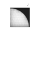
- FIG. 5 is a diagram showing an example of the simulation result of the brightness according to the embodiment of FIG. 1, and shows the region of the upper right 1/4 of the circular light emitting surface. In FIG. 5, it can be seen that the light emitting surface has uniform brightness including the end portion (outer peripheral portion).
- the amount of light of each light source 3 is constant, but the amount of light of the light source 3 arranged at the end of the light emitting surface may be increased. That is, the light from the surrounding light source 3 is superimposed on the light from the light source 3 directly under the light source 3 other than the end portion, but the light source 3 at the end portion has no light superimposed from the end portion side and has brightness. This is to make up for the shortage of light sources.
- local dimming for controlling the individual lighting of the light source 3 is performed, and local dimming may be performed in units of a series of areas.
- local dimming when local dimming is performed in units of areas extending in the directions of each line L1 to L16 (areas in which adjacent lines are grouped), an area that is turned off and an area that is turned on are used. It has the advantage of improving the appearance of the boundary with. This is because the direction of the arrangement of the light sources 3 and the direction of the boundary of the region where the local dimming is performed coincide with each other.
- FIG. 6 is a diagram showing an example in which lighting / extinguishing is performed in units of regions extending in the horizontal direction by local dimming.
- a OFF indicates an area where the light is turned off
- a ON indicates an area where the light is turned on.
- the line on the area A OFF side is turned off and the line on the area A ON side is turned on, so that the boundary appears in a straight line and the appearance is improved.
- the planar illuminating device is a planar illuminating device having a light emitting surface having an outer shape other than a rectangular shape, and the light emitting surface has a light source at a predetermined pitch in one direction along the light emitting surface.
- the second type of rows contained within are arranged in a direction orthogonal to one direction.
- first type row and the second type row are arranged according to the distance from the center line extending in the direction orthogonal to one direction of the light emitting surface to the end portion of the light emitting surface in one direction. Thereby, the uniformity of the brightness at the end portion can be improved.
- the position of the light source arranged at the end of the light emitting surface in the first type row or the second type row is adjusted according to the position of the end portion. Thereby, the uniformity of the brightness at the end portion can be further improved.
- a reflector having a reflecting portion surrounding each of the light sources in the first type row and the second type row. As a result, it is possible to reflect light in a required direction and improve the brightness uniformity of the light emitting surface carried by each light source.
- the shape of the reflecting portion provided corresponding to the light source arranged at the end of the light emitting surface in the first type row or the second type row is adjusted according to the position of the end portion. Thereby, the uniformity of the brightness at the end portion can be further improved.
- the amount of light is increased for the light source arranged at the end of the light emitting surface in the first type row or the second type row, and the amount of light is constant for the other light sources. As a result, it is possible to compensate for the lack of brightness at the end portion and further improve the uniformity of brightness at the end portion.
- the lighting or lighting of the light source is controlled in units of an area composed of a plurality of adjacent rows arranged in a direction orthogonal to one direction. As a result, the appearance of the boundary of the area can be improved.
- the present invention is not limited by the above-described embodiment.
- the present invention also includes a configuration in which the above-mentioned components are appropriately combined. Further, further effects and modifications can be easily derived by those skilled in the art. Therefore, the broader aspect of the present invention is not limited to the above-described embodiment, and various modifications can be made.
- 1 planar lighting device 2 substrate, 3, 31-34 light source, 4 reflector, 4a reflective surface, 41-46 reflector, L1-L16 line, C center line
Landscapes
- Physics & Mathematics (AREA)
- Engineering & Computer Science (AREA)
- General Engineering & Computer Science (AREA)
- Nonlinear Science (AREA)
- Mathematical Physics (AREA)
- Chemical & Material Sciences (AREA)
- Crystallography & Structural Chemistry (AREA)
- General Physics & Mathematics (AREA)
- Optics & Photonics (AREA)
- Planar Illumination Modules (AREA)
- Non-Portable Lighting Devices Or Systems Thereof (AREA)
- Liquid Crystal (AREA)
Applications Claiming Priority (2)
| Application Number | Priority Date | Filing Date | Title |
|---|---|---|---|
| JP2020030444A JP7307009B2 (ja) | 2020-02-26 | 2020-02-26 | 面状照明装置 |
| JP2020-030444 | 2020-02-26 |
Publications (1)
| Publication Number | Publication Date |
|---|---|
| WO2021171878A1 true WO2021171878A1 (ja) | 2021-09-02 |
Family
ID=77490436
Family Applications (1)
| Application Number | Title | Priority Date | Filing Date |
|---|---|---|---|
| PCT/JP2021/002725 Ceased WO2021171878A1 (ja) | 2020-02-26 | 2021-01-27 | 面状照明装置 |
Country Status (2)
| Country | Link |
|---|---|
| JP (1) | JP7307009B2 (https=) |
| WO (1) | WO2021171878A1 (https=) |
Cited By (1)
| Publication number | Priority date | Publication date | Assignee | Title |
|---|---|---|---|---|
| JPWO2024034296A1 (https=) * | 2022-08-09 | 2024-02-15 |
Citations (3)
| Publication number | Priority date | Publication date | Assignee | Title |
|---|---|---|---|---|
| JP2010049865A (ja) * | 2008-08-20 | 2010-03-04 | Sharp Corp | 照明機器 |
| JP2012256572A (ja) * | 2011-06-10 | 2012-12-27 | Toshiba Lighting & Technology Corp | 照明装置 |
| JP2013143239A (ja) * | 2012-01-10 | 2013-07-22 | Sharp Corp | Ledバックライト装置および液晶表示装置 |
-
2020
- 2020-02-26 JP JP2020030444A patent/JP7307009B2/ja active Active
-
2021
- 2021-01-27 WO PCT/JP2021/002725 patent/WO2021171878A1/ja not_active Ceased
Patent Citations (3)
| Publication number | Priority date | Publication date | Assignee | Title |
|---|---|---|---|---|
| JP2010049865A (ja) * | 2008-08-20 | 2010-03-04 | Sharp Corp | 照明機器 |
| JP2012256572A (ja) * | 2011-06-10 | 2012-12-27 | Toshiba Lighting & Technology Corp | 照明装置 |
| JP2013143239A (ja) * | 2012-01-10 | 2013-07-22 | Sharp Corp | Ledバックライト装置および液晶表示装置 |
Cited By (4)
| Publication number | Priority date | Publication date | Assignee | Title |
|---|---|---|---|---|
| JPWO2024034296A1 (https=) * | 2022-08-09 | 2024-02-15 | ||
| JP7546185B1 (ja) | 2022-08-09 | 2024-09-05 | ミネベアミツミ株式会社 | 面状照明装置 |
| JP2024147823A (ja) * | 2022-08-09 | 2024-10-16 | ミネベアミツミ株式会社 | 面状照明装置 |
| JP7588737B2 (ja) | 2022-08-09 | 2024-11-22 | ミネベアミツミ株式会社 | 面状照明装置 |
Also Published As
| Publication number | Publication date |
|---|---|
| JP7307009B2 (ja) | 2023-07-11 |
| JP2021136117A (ja) | 2021-09-13 |
Similar Documents
| Publication | Publication Date | Title |
|---|---|---|
| TWI460501B (zh) | 平面型光源 | |
| JP4926928B2 (ja) | 照明装置および液晶表示装置 | |
| KR100638658B1 (ko) | 백라이트 장치 | |
| JP2009542017A (ja) | オプトエレクトロニクスコンポーネントおよび照明装置 | |
| JP2002324409A (ja) | 色付き照明装置 | |
| JP2004163886A (ja) | 平板表示素子用照明装置 | |
| JP2009193669A (ja) | 液晶ディスプレイ機器 | |
| KR20060124831A (ko) | 백라이트 어셈블리 및 이를 구비한 액정표시장치 | |
| KR20060070159A (ko) | 백라이트 시스템 및 이를 채용한 액정표시장치 | |
| KR20020096910A (ko) | 직하형 조명장치 | |
| CN101688647A (zh) | 照明装置和液晶显示装置 | |
| KR20080080150A (ko) | 조명 장치 | |
| CN103874878A (zh) | 分裂波束照明器和照明系统 | |
| RU2523779C2 (ru) | Оптический элемент для асимметричного распределения света | |
| TW201243457A (en) | Surface light-source apparatus and liquid crystal display apparatus | |
| KR20090131886A (ko) | 면 광원 장치 및 이를 구비하는 백라이트 유닛 | |
| KR100708147B1 (ko) | 발광소자 클러스터 및 이를 채용한 직하발광형 백라이트유닛 및 액정표시장치 | |
| JP2020013714A (ja) | 面状照明装置 | |
| TW201619541A (zh) | 光源模組與光源單元 | |
| WO2021171878A1 (ja) | 面状照明装置 | |
| TWI353473B (en) | Backlight unit and liquid crystal display | |
| US7832893B2 (en) | Direct type backlight assembly and liquid crystal display device having the same | |
| KR20090090030A (ko) | 발광다이오드 램프를 이용한 직하 조광형 백라이트 장치 | |
| EP3279555B1 (en) | Lens for light source, illumination device, and display device | |
| JP2007108543A (ja) | 光学フィルム及び該光学フィルムを用いた照明装置 |
Legal Events
| Date | Code | Title | Description |
|---|---|---|---|
| 121 | Ep: the epo has been informed by wipo that ep was designated in this application |
Ref document number: 21759018 Country of ref document: EP Kind code of ref document: A1 |
|
| NENP | Non-entry into the national phase |
Ref country code: DE |
|
| 122 | Ep: pct application non-entry in european phase |
Ref document number: 21759018 Country of ref document: EP Kind code of ref document: A1 |