WO2021171648A1 - Vacuum heat insulator, and method for inspecting same - Google Patents
Vacuum heat insulator, and method for inspecting same Download PDFInfo
- Publication number
- WO2021171648A1 WO2021171648A1 PCT/JP2020/029057 JP2020029057W WO2021171648A1 WO 2021171648 A1 WO2021171648 A1 WO 2021171648A1 JP 2020029057 W JP2020029057 W JP 2020029057W WO 2021171648 A1 WO2021171648 A1 WO 2021171648A1
- Authority
- WO
- WIPO (PCT)
- Prior art keywords
- heat insulating
- vacuum
- power
- vacuum insulation
- transmission unit
- Prior art date
Links
Images


Classifications
-
- B—PERFORMING OPERATIONS; TRANSPORTING
- B65—CONVEYING; PACKING; STORING; HANDLING THIN OR FILAMENTARY MATERIAL
- B65D—CONTAINERS FOR STORAGE OR TRANSPORT OF ARTICLES OR MATERIALS, e.g. BAGS, BARRELS, BOTTLES, BOXES, CANS, CARTONS, CRATES, DRUMS, JARS, TANKS, HOPPERS, FORWARDING CONTAINERS; ACCESSORIES, CLOSURES, OR FITTINGS THEREFOR; PACKAGING ELEMENTS; PACKAGES
- B65D25/00—Details of other kinds or types of rigid or semi-rigid containers
- B65D25/02—Internal fittings
-
- B—PERFORMING OPERATIONS; TRANSPORTING
- B65—CONVEYING; PACKING; STORING; HANDLING THIN OR FILAMENTARY MATERIAL
- B65D—CONTAINERS FOR STORAGE OR TRANSPORT OF ARTICLES OR MATERIALS, e.g. BAGS, BARRELS, BOTTLES, BOXES, CANS, CARTONS, CRATES, DRUMS, JARS, TANKS, HOPPERS, FORWARDING CONTAINERS; ACCESSORIES, CLOSURES, OR FITTINGS THEREFOR; PACKAGING ELEMENTS; PACKAGES
- B65D81/00—Containers, packaging elements, or packages, for contents presenting particular transport or storage problems, or adapted to be used for non-packaging purposes after removal of contents
- B65D81/38—Containers, packaging elements, or packages, for contents presenting particular transport or storage problems, or adapted to be used for non-packaging purposes after removal of contents with thermal insulation
- B65D81/3825—Containers, packaging elements, or packages, for contents presenting particular transport or storage problems, or adapted to be used for non-packaging purposes after removal of contents with thermal insulation rigid container being in the form of a box, tray or like container with one or more containers located inside the external container
- B65D81/3834—Containers, packaging elements, or packages, for contents presenting particular transport or storage problems, or adapted to be used for non-packaging purposes after removal of contents with thermal insulation rigid container being in the form of a box, tray or like container with one or more containers located inside the external container the external tray being formed of different materials, e.g. laminated or foam filling between walls
-
- G—PHYSICS
- G01—MEASURING; TESTING
- G01L—MEASURING FORCE, STRESS, TORQUE, WORK, MECHANICAL POWER, MECHANICAL EFFICIENCY, OR FLUID PRESSURE
- G01L11/00—Measuring steady or quasi-steady pressure of a fluid or a fluent solid material by means not provided for in group G01L7/00 or G01L9/00
- G01L11/002—Measuring steady or quasi-steady pressure of a fluid or a fluent solid material by means not provided for in group G01L7/00 or G01L9/00 by thermal means, e.g. hypsometer
-
- B—PERFORMING OPERATIONS; TRANSPORTING
- B65—CONVEYING; PACKING; STORING; HANDLING THIN OR FILAMENTARY MATERIAL
- B65D—CONTAINERS FOR STORAGE OR TRANSPORT OF ARTICLES OR MATERIALS, e.g. BAGS, BARRELS, BOTTLES, BOXES, CANS, CARTONS, CRATES, DRUMS, JARS, TANKS, HOPPERS, FORWARDING CONTAINERS; ACCESSORIES, CLOSURES, OR FITTINGS THEREFOR; PACKAGING ELEMENTS; PACKAGES
- B65D51/00—Closures not otherwise provided for
- B65D51/24—Closures not otherwise provided for combined or co-operating with auxiliary devices for non-closing purposes
-
- B—PERFORMING OPERATIONS; TRANSPORTING
- B65—CONVEYING; PACKING; STORING; HANDLING THIN OR FILAMENTARY MATERIAL
- B65D—CONTAINERS FOR STORAGE OR TRANSPORT OF ARTICLES OR MATERIALS, e.g. BAGS, BARRELS, BOTTLES, BOXES, CANS, CARTONS, CRATES, DRUMS, JARS, TANKS, HOPPERS, FORWARDING CONTAINERS; ACCESSORIES, CLOSURES, OR FITTINGS THEREFOR; PACKAGING ELEMENTS; PACKAGES
- B65D79/00—Kinds or details of packages, not otherwise provided for
- B65D79/02—Arrangements or devices for indicating incorrect storage or transport
-
- B—PERFORMING OPERATIONS; TRANSPORTING
- B65—CONVEYING; PACKING; STORING; HANDLING THIN OR FILAMENTARY MATERIAL
- B65D—CONTAINERS FOR STORAGE OR TRANSPORT OF ARTICLES OR MATERIALS, e.g. BAGS, BARRELS, BOTTLES, BOXES, CANS, CARTONS, CRATES, DRUMS, JARS, TANKS, HOPPERS, FORWARDING CONTAINERS; ACCESSORIES, CLOSURES, OR FITTINGS THEREFOR; PACKAGING ELEMENTS; PACKAGES
- B65D81/00—Containers, packaging elements, or packages, for contents presenting particular transport or storage problems, or adapted to be used for non-packaging purposes after removal of contents
- B65D81/18—Containers, packaging elements, or packages, for contents presenting particular transport or storage problems, or adapted to be used for non-packaging purposes after removal of contents providing specific environment for contents, e.g. temperature above or below ambient
- B65D81/20—Containers, packaging elements, or packages, for contents presenting particular transport or storage problems, or adapted to be used for non-packaging purposes after removal of contents providing specific environment for contents, e.g. temperature above or below ambient under vacuum or superatmospheric pressure, or in a special atmosphere, e.g. of inert gas
- B65D81/2007—Containers, packaging elements, or packages, for contents presenting particular transport or storage problems, or adapted to be used for non-packaging purposes after removal of contents providing specific environment for contents, e.g. temperature above or below ambient under vacuum or superatmospheric pressure, or in a special atmosphere, e.g. of inert gas under vacuum
- B65D81/2015—Containers, packaging elements, or packages, for contents presenting particular transport or storage problems, or adapted to be used for non-packaging purposes after removal of contents providing specific environment for contents, e.g. temperature above or below ambient under vacuum or superatmospheric pressure, or in a special atmosphere, e.g. of inert gas under vacuum in an at least partially rigid container
-
- B—PERFORMING OPERATIONS; TRANSPORTING
- B65—CONVEYING; PACKING; STORING; HANDLING THIN OR FILAMENTARY MATERIAL
- B65D—CONTAINERS FOR STORAGE OR TRANSPORT OF ARTICLES OR MATERIALS, e.g. BAGS, BARRELS, BOTTLES, BOXES, CANS, CARTONS, CRATES, DRUMS, JARS, TANKS, HOPPERS, FORWARDING CONTAINERS; ACCESSORIES, CLOSURES, OR FITTINGS THEREFOR; PACKAGING ELEMENTS; PACKAGES
- B65D81/00—Containers, packaging elements, or packages, for contents presenting particular transport or storage problems, or adapted to be used for non-packaging purposes after removal of contents
- B65D81/24—Adaptations for preventing deterioration or decay of contents; Applications to the container or packaging material of food preservatives, fungicides, pesticides or animal repellants
-
- B—PERFORMING OPERATIONS; TRANSPORTING
- B65—CONVEYING; PACKING; STORING; HANDLING THIN OR FILAMENTARY MATERIAL
- B65D—CONTAINERS FOR STORAGE OR TRANSPORT OF ARTICLES OR MATERIALS, e.g. BAGS, BARRELS, BOTTLES, BOXES, CANS, CARTONS, CRATES, DRUMS, JARS, TANKS, HOPPERS, FORWARDING CONTAINERS; ACCESSORIES, CLOSURES, OR FITTINGS THEREFOR; PACKAGING ELEMENTS; PACKAGES
- B65D81/00—Containers, packaging elements, or packages, for contents presenting particular transport or storage problems, or adapted to be used for non-packaging purposes after removal of contents
- B65D81/38—Containers, packaging elements, or packages, for contents presenting particular transport or storage problems, or adapted to be used for non-packaging purposes after removal of contents with thermal insulation
- B65D81/3813—Containers, packaging elements, or packages, for contents presenting particular transport or storage problems, or adapted to be used for non-packaging purposes after removal of contents with thermal insulation rigid container being in the form of a box, tray or like container
- B65D81/3816—Containers, packaging elements, or packages, for contents presenting particular transport or storage problems, or adapted to be used for non-packaging purposes after removal of contents with thermal insulation rigid container being in the form of a box, tray or like container formed of foam material
-
- B—PERFORMING OPERATIONS; TRANSPORTING
- B65—CONVEYING; PACKING; STORING; HANDLING THIN OR FILAMENTARY MATERIAL
- B65D—CONTAINERS FOR STORAGE OR TRANSPORT OF ARTICLES OR MATERIALS, e.g. BAGS, BARRELS, BOTTLES, BOXES, CANS, CARTONS, CRATES, DRUMS, JARS, TANKS, HOPPERS, FORWARDING CONTAINERS; ACCESSORIES, CLOSURES, OR FITTINGS THEREFOR; PACKAGING ELEMENTS; PACKAGES
- B65D81/00—Containers, packaging elements, or packages, for contents presenting particular transport or storage problems, or adapted to be used for non-packaging purposes after removal of contents
- B65D81/38—Containers, packaging elements, or packages, for contents presenting particular transport or storage problems, or adapted to be used for non-packaging purposes after removal of contents with thermal insulation
- B65D81/3813—Containers, packaging elements, or packages, for contents presenting particular transport or storage problems, or adapted to be used for non-packaging purposes after removal of contents with thermal insulation rigid container being in the form of a box, tray or like container
- B65D81/3818—Containers, packaging elements, or packages, for contents presenting particular transport or storage problems, or adapted to be used for non-packaging purposes after removal of contents with thermal insulation rigid container being in the form of a box, tray or like container formed with double walls, i.e. hollow
-
- F—MECHANICAL ENGINEERING; LIGHTING; HEATING; WEAPONS; BLASTING
- F16—ENGINEERING ELEMENTS AND UNITS; GENERAL MEASURES FOR PRODUCING AND MAINTAINING EFFECTIVE FUNCTIONING OF MACHINES OR INSTALLATIONS; THERMAL INSULATION IN GENERAL
- F16L—PIPES; JOINTS OR FITTINGS FOR PIPES; SUPPORTS FOR PIPES, CABLES OR PROTECTIVE TUBING; MEANS FOR THERMAL INSULATION IN GENERAL
- F16L59/00—Thermal insulation in general
- F16L59/06—Arrangements using an air layer or vacuum
- F16L59/065—Arrangements using an air layer or vacuum using vacuum
-
- G—PHYSICS
- G01—MEASURING; TESTING
- G01L—MEASURING FORCE, STRESS, TORQUE, WORK, MECHANICAL POWER, MECHANICAL EFFICIENCY, OR FLUID PRESSURE
- G01L21/00—Vacuum gauges
- G01L21/10—Vacuum gauges by measuring variations in the heat conductivity of the medium, the pressure of which is to be measured
- G01L21/14—Vacuum gauges by measuring variations in the heat conductivity of the medium, the pressure of which is to be measured using thermocouples
-
- G—PHYSICS
- G01—MEASURING; TESTING
- G01N—INVESTIGATING OR ANALYSING MATERIALS BY DETERMINING THEIR CHEMICAL OR PHYSICAL PROPERTIES
- G01N25/00—Investigating or analyzing materials by the use of thermal means
- G01N25/18—Investigating or analyzing materials by the use of thermal means by investigating thermal conductivity
-
- G—PHYSICS
- G08—SIGNALLING
- G08C—TRANSMISSION SYSTEMS FOR MEASURED VALUES, CONTROL OR SIMILAR SIGNALS
- G08C17/00—Arrangements for transmitting signals characterised by the use of a wireless electrical link
-
- G—PHYSICS
- G08—SIGNALLING
- G08C—TRANSMISSION SYSTEMS FOR MEASURED VALUES, CONTROL OR SIMILAR SIGNALS
- G08C17/00—Arrangements for transmitting signals characterised by the use of a wireless electrical link
- G08C17/02—Arrangements for transmitting signals characterised by the use of a wireless electrical link using a radio link
-
- H—ELECTRICITY
- H04—ELECTRIC COMMUNICATION TECHNIQUE
- H04Q—SELECTING
- H04Q9/00—Arrangements in telecontrol or telemetry systems for selectively calling a substation from a main station, in which substation desired apparatus is selected for applying a control signal thereto or for obtaining measured values therefrom
-
- H—ELECTRICITY
- H04—ELECTRIC COMMUNICATION TECHNIQUE
- H04Q—SELECTING
- H04Q2209/00—Arrangements in telecontrol or telemetry systems
- H04Q2209/40—Arrangements in telecontrol or telemetry systems using a wireless architecture
-
- H—ELECTRICITY
- H04—ELECTRIC COMMUNICATION TECHNIQUE
- H04Q—SELECTING
- H04Q2209/00—Arrangements in telecontrol or telemetry systems
- H04Q2209/40—Arrangements in telecontrol or telemetry systems using a wireless architecture
- H04Q2209/43—Arrangements in telecontrol or telemetry systems using a wireless architecture using wireless personal area networks [WPAN], e.g. 802.15, 802.15.1, 802.15.4, Bluetooth or ZigBee
-
- H—ELECTRICITY
- H04—ELECTRIC COMMUNICATION TECHNIQUE
- H04Q—SELECTING
- H04Q2209/00—Arrangements in telecontrol or telemetry systems
- H04Q2209/80—Arrangements in the sub-station, i.e. sensing device
- H04Q2209/88—Providing power supply at the sub-station
- H04Q2209/886—Providing power supply at the sub-station using energy harvesting, e.g. solar, wind or mechanical
Definitions
- This disclosure relates to vacuum insulation and this inspection system.
- the heat insulating container of Patent Document 1 As a conventional vacuum heat insulating body, the heat insulating container of Patent Document 1 is known.
- the heat insulating container includes a container and a heat insulating bag for accommodating the container.
- the bag has a double wall, and the vacuum heat insulating material is housed between the double walls.
- the transportation of pharmaceuticals and the like requires strict temperature control to maintain a low temperature for a predetermined time regardless of the outside temperature.
- the vacuum heat insulating material as described above may have a low degree of vacuum due to external force, deterioration over time, etc., and the heat insulating performance may be lowered. Therefore, it is important to inspect the heat insulating performance of the vacuum heat insulating material.
- the vacuum heat insulating material may be damaged because the test device needs to be brought into contact with the vacuum heat insulating material.
- the present disclosure has been made to solve such a problem, and an object of the present invention is to provide a vacuum heat insulating body capable of safely inspecting the heat insulating performance in a short time and this inspection system.
- the vacuum heat insulating body includes a core material, a pressure sensor that detects pressure, a transmission unit that transmits the pressure detected by the pressure sensor by wireless communication, and power to the pressure sensor and the transmission unit.
- a core material, a pressure sensor, a transmission unit, and an outer cover material having a gas barrier property in which the inside containing the power supply unit is decompressed are provided.
- the pressure inside the outer cover material is detected by the pressure sensor, and this detected pressure is transmitted by wireless communication by the transmission unit. Since this pressure can be detected in a short time and the detected pressure can be obtained without contacting the outer cover material, the heat insulating performance of the vacuum insulator can be safely inspected in a short time based on the detected pressure. Can be done.
- the transmission unit may transmit the detection pressure by NFC (Near Field Communication).
- NFC Near Field Communication
- the receiving unit can receive the detected pressure from the transmitting unit without pairing, and can inspect the heat insulating performance of the vacuum heat insulating body in a short time based on the detected pressure.
- the transmission unit may transmit the detection pressure by BLE (Bluetooth Low Energy) communication.
- BLE Bluetooth Low Energy
- the receiving unit can receive the detection pressure from the transmitting unit arranged apart from each other, and the degree of freedom in arranging the receiving unit is increased.
- the power supply unit may include a power receiving coil that receives non-contact power from the power transmitting coil outside the outer cover material. .. According to this configuration, by not using the battery for the power supply unit, it is possible to prevent the inspectability due to insufficient power and the decrease in the degree of vacuum due to the liquid leakage of the battery.
- the power receiving coil may receive power by a magnetic field resonance method.
- the power receiving coil can receive power from the power transmission coils arranged apart from each other, and even if the vacuum heat insulating body is covered with a thick protective layer or the like, the protective layer is a vacuum heat insulating body. The insulation performance of the vacuum insulation can be inspected without removing it from.
- the power receiving coil may receive power by an electromagnetic induction method. According to this configuration, since the power supply unit can be miniaturized, it is possible to reduce the deterioration of the heat insulation performance due to the power supply unit while suppressing the increase in size of the vacuum heat insulating body.
- the power supply unit may include a battery storing the power. According to this configuration, since the power supply unit can be miniaturized, it is possible to reduce the deterioration of the heat insulation performance due to the power supply unit while suppressing the increase in size of the vacuum heat insulating body.
- the inspection system for the vacuum insulation body according to the eighth aspect of the present invention is transmitted by the vacuum insulation body according to any one of the first to sixth aspects, the power transmission unit that transmits the electric power to the power supply unit, and the transmission unit.
- An inspection device having a receiving unit for receiving the detected pressure may be provided. According to this configuration, the heat insulating performance of the vacuum heat insulating body can be safely inspected in a short time.
- the vacuum insulation body inspection system includes the vacuum insulation body of the seventh aspect and an inspection device having a receiving unit for receiving the detection pressure transmitted by the transmitting unit. .. According to this configuration, the heat insulating performance of the vacuum heat insulating body can be safely inspected in a short time.
- the present disclosure has the effect that the heat insulating performance can be safely inspected in a short time in the vacuum heat insulating body and this inspection system.
- FIG. 5 is a cross-sectional view schematically showing the wireless vacuum gauge device of FIG.
- FIG. 5 is a cross-sectional view schematically showing an inner member, a core material, and an outer member of the first vacuum heat insulating body of FIG.
- FIG. 8 is a cross-sectional view schematically showing a heat insulating box and a heat storage container in which the heat insulating lid and the heat storage lid of FIG. 8 are opened.
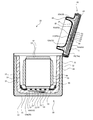
- the vacuum insulation body 10 As shown in FIGS. 1 and 2, the vacuum insulation body 10 according to the first embodiment is used as a heat insulating box 20 for transporting or storing articles such as pharmaceuticals, specimens, and foods, for example.
- the vacuum heat insulating body 10 is used for the heat insulating box 20
- the use of the vacuum heat insulating body 10 is not limited to this.
- the heat insulating box 20 includes a heat insulating container 30 and a heat insulating lid 40.
- the heat insulating container 30 has a first exterior member 31, a first protective layer 32 and a first vacuum heat insulating body 10a
- the heat insulating lid 40 has a second exterior member 41, a covering layer 45, a second protective layer 42 and a second vacuum heat insulating body. It has a body 10b.
- the first vacuum heat insulating body 10a and the second vacuum heat insulating body 10b may be simply referred to as the vacuum heat insulating body 10. The details of the vacuum heat insulating body 10 will be described later.
- the first protective layer 32 is arranged in the first exterior member 31, the first vacuum heat insulating body 10a is arranged in the first protective layer 32, and the first vacuum heat insulating body 10a has an internal space inside the first protective layer 32.
- the heat insulating lid 40 covers the opening of the internal space, and the heat insulating box 20 is closed.
- the internal space side of the first vacuum heat insulating body 10a with respect to the first exterior member 31 is referred to as the inside, and the opposite side thereof is referred to as the outside.
- the side of the heat insulating container 30 is referred to as the lower side and the opposite side is referred to as the upper side, but the arrangement of the heat insulating box 20 is not limited to this. ..
- the first exterior member 31 of the heat insulating container 30 has a box shape with an open upper end, and is made of, for example, a synthetic fiber fabric, plastic, corrugated cardboard, or the like.
- the first exterior member 31 accommodates the first protective layer 32 inside and covers the outer surface of the first protective layer 32.
- a hand-carrying belt or the like may be attached to the first exterior member 31 so that the user can easily hold the heat insulating box 20.
- the first protective layer 32 has, for example, a box shape with an open upper end, and is formed of, for example, a cushioning material such as Styrofoam.
- the first protective layer 32 accommodates the first vacuum heat insulating body 10a inside, covers the outer surface of the first vacuum heat insulating body 10a, and damages the first vacuum heat insulating body 10a and the article due to external impact and vibration. Is prevented.
- the first protective layer 32 has a first lower wall 33 and four first side walls 34, which have a rectangular flat plate shape.
- the first lower wall 33 is arranged at the lower end of the first protective layer 32.
- the four first side walls 34 rise upward from the outer peripheral edge of the first lower wall 33, and the first side walls 34 adjacent to each other are connected to each other, and the lower end opening is closed by the first side wall 34 in a square tube shape. Have.
- the first vacuum heat insulating body 10a has a box shape with an open upper end, and has a second lower wall 11 and four second side walls 12.
- the second lower wall 11 and the second side wall 12 have a rectangular flat plate shape, and the second lower wall 11 is arranged at the lower end of the first vacuum heat insulating body 10a.
- the four second side walls 12 rise upward from the outer peripheral edge of the second lower wall 11, and the second side walls 12 adjacent to each other are connected to each other, and the lower end opening is closed by the second lower wall 11. It has a tubular shape.
- the outer surface of the heat insulating container 30 is formed by the first exterior member 31, the inner surface of the heat insulating container 30 is formed by the first vacuum heat insulating body 10a, and the upper end opening of the heat insulating container 30 is the first. Corresponds to the upper end opening of the vacuum insulation body 10a.
- the internal space of the heat insulating container 30 corresponds to the internal space of the first vacuum heat insulating body 10a, and this internal space has a rectangular parallelepiped shape surrounded by the second lower wall 11 and the four second side walls 12 through the upper end opening. It communicates with the outside.
- the heat insulating lid 40 has an upper lid portion 43 and a lower lid portion 44.
- the upper lid portion 43 has a rectangular flat plate shape.
- the lower lid portion 44 has a rectangular flat plate-shaped flat plate portion and a protruding portion protruding from the lower surface of the flat plate portion.
- the flat plate portion of the lower lid portion 44 has a lower surface facing the upper end opening of the heat insulating container 30 and an upper surface opposite to the lower surface.
- the upper surface of the lower lid portion 44 is in contact with the lower surface of the upper lid portion 43 so as to face the lower surface of the upper lid portion 43, whereby the heat insulating lid 40 is formed.
- the lower surface of the lower lid portion 44 comes into contact with the upper end of the first protective layer 32 and the upper end of the first vacuum heat insulating body 10a. .. Further, the protruding portion of the lower lid portion 44 fits inside the first vacuum heat insulating body 10a, and the outer peripheral surface of the lower lid portion 44 abuts or approaches the inner surface of the first vacuum heat insulating body 10a with a gap. There is.
- the upper lid portion 43 is formed by the second exterior member 41, the upper portion 45a of the coating layer 45, and the upper portion 42a of the second protective layer 42, and the lower lid portion 44 is the coating layer. It is formed by the lower portion 45b of the 45, the lower portion 42b of the second protective layer 42, and the second vacuum heat insulating body 10b.
- the second exterior member 41 is made of, for example, a synthetic fiber fabric, plastic, corrugated cardboard, or other material.
- the second protective layer 42 is formed of a cushioning material such as Styrofoam.
- the coating layer 45 may be formed of a cushioning material such as styrofoam like the first protective layer 32 and the second protective layer 42, or may be made of soft urethane foam or the like in order to enhance the airtightness of the upper end opening of the heat insulating container 30. It may be formed by a cushioning material.
- the upper portion 45a of the coating layer 45 and the upper portion 42a of the second protective layer 42 may be integrally formed when both are made of the same material such as Styrofoam.
- the lower portion 45b of the coating layer 45 and the lower portion 42b of the second protective layer 42 may be integrally formed when both are made of the same material such as Styrofoam.
- the upper surface and side surfaces of the upper portion 42a are covered with the upper portion 45a, and the upper portion 45a is covered with the second exterior member 41. Therefore, the upper surface and the side surface of the upper lid portion 43 are composed of the second exterior member 41, and the lower surface of the upper lid portion 43 is composed of the upper portion 42a. Further, the lower portion 42b is covered with a surface other than the upper surface by the lower portion 45b. Therefore, the lower surface and side surfaces of the flat plate portion and the protruding portion of the lower lid portion 44 are composed of the lower portion 45b, and the upper surface of the lower lid portion 44 is composed of the lower portion 42b.
- the lower portion 42b is provided with a recess that is recessed from the upper surface thereof, and the second vacuum heat insulating body 10b is housed in the recess.
- the upper surface of the second vacuum heat insulating body 10b and the upper surface of the lower portion 42b are arranged so as to be flush with each other.
- the second protective layer 42 formed by the upper portion 42a and the lower portion 42b is housed in the coating layer 45 formed by the upper portion 45a and the lower portion 45b, and the second protective layer 42 formed by the upper portion 42a and the lower portion 42b is housed in the second protective layer 42.
- the second vacuum insulation body 10b is arranged.
- the upper surface and the side surface are composed of the second exterior member 41, and the lower surface and the protruding portion are composed of the covering layer 45.
- the second vacuum heat insulating body 10b is arranged in the heat insulating lid 40 and is covered with the second protective layer 42.
- the second exterior member 41 may be connected to the upper end of the first exterior member 31 so that the heat insulating lid 40 can open and close the upper end opening of the heat insulating container 30.
- the vacuum heat insulating body 10 includes a core material 13, an outer cover material 14, and a wireless vacuum gauge device 50.
- the wireless vacuum gauge device 50 includes a pressure sensor 51, a transmission unit 52, a power supply unit 53, and a housing 54.
- the core material 13 is a porous body and is formed of a material having low thermal conductivity, and serves as a skeleton of the vacuum heat insulating material to form a heat insulating space.
- an open cell such as open cell urethane foam, a foamed resin material such as expanded polystyrene, an aggregate of fibers, and an aggregate of inorganic fine particles are used.
- the open cell urethane foam is a polyurethane foam having open cells in which a plurality of bubbles communicate with each other.
- the outer cover material 14 is formed of a non-metal material such as resin, has a gas barrier property, and keeps the pressure inside the vacuum heat insulating body 10 low.
- the outer cover material 14 is a laminate of a heat-weldable thermoplastic resin layer, an air barrier layer such as an ethylene-vinyl alcohol copolymer (EVOH) or a polyvinyl alcohol polymer, and a water vapor barrier layer such as polypropylene. It may have a structure.
- the outer cover material 14 accommodates the core material 13 and the wireless vacuum gauge device 50, and covers them.
- the gas adsorbent may be housed in the outer cover material 14. The gas adsorbent adsorbs gases such as water vapor and air that remain or invade inside the outer cover material 14. As a result, the pressure inside the outer cover material 14 can be kept low.
- the pressure sensor 51 is a sensor that detects the pressure (atmospheric pressure) inside the outer cover material 14, is electrically connected to the transmission unit 52, and outputs the detected pressure to the transmission unit 52.
- the pressure sensor 51 is provided with, for example, a heater and a thermocouple, and measures the atmospheric pressure (degree of vacuum) by measuring the heat conduction characteristics of the surroundings from the temperature detected by the thermocouple when the heater is heated. Used.
- the pressure sensor 51 is not limited to this, and for example, a microelectromechanical system (MEMS) such as a piezo type, a capacitance type, and a vibration type is used.
- MEMS microelectromechanical system
- the transmission unit 52 is an element that transmits the pressure detected by the pressure sensor 51 by wireless communication, and has, for example, a communication control IC, a memory, and an antenna.
- the transmission unit 52 stores its own identification information (transmission unit ID) in a memory, and the communication control IC transmits the transmission unit ID together with the detection pressure from the antenna.
- the transmission unit 52 is a short-range wireless communication using a frequency in the 13.56 MHz band, and transmits the detection pressure by NFC (Near Field Communication).
- NFC Near Field Communication
- the power supply unit 53 is electrically connected to the pressure sensor 51 and the transmission unit 52, and supplies electric power to these.
- the power supply unit 53 has a power supply control IC and a magnetic field resonance type wireless power supply power receiving unit.
- the power receiving unit includes a secondary coil (power receiving coil 55) that receives non-contact power from the primary coil (power transmission coil) outside the outer cover material 14.
- the power receiving coil 55 is a coil in which a conducting wire is wound around a central axis, and is, for example, a solenoid type coil or a spiral type coil.
- the power receiving coil 55 receives the electric power transmitted from the power transmitting coil, and the power supply control IC supplies this electric power to the pressure sensor 51 and the transmitting unit 52.
- the housing 54 is made of a non-metal such as resin, and houses the pressure sensor 51, the transmission unit 52, and the power supply unit 53 inside the housing 54, and is arranged in the outer cover material 14.
- the housing 54 has an internal space, and the housing 54 is provided with a plurality of through holes 56. Since the air inside the housing 54 is discharged through the through hole 56, the pressure inside and outside the housing 54 is even inside the outer cover material 14. Further, the space inside the housing 54 may be potted with resin to protect the circuit components. Also in this case, the pressure sensor 51 and the through hole 56 are not filled with the resin, and the pressure inside the housing 54 detected by the pressure sensor 51 and the pressure outside the housing 54 are equalized.
- the housing 54 has, for example, a flat plate shape, and has a pair of walls facing each other and four walls connecting them.
- One wall (fixed wall 57) of the pair of walls is flat, and the pressure sensor 51, the transmission unit 52, and the power supply unit 53 are mounted side by side. Therefore, the dimension between the pair of walls (thickness of the housing 54) can be reduced in the direction orthogonal to the line-up direction.
- the thickness of the core material 13 overlapping the housing 54 of the wireless pressure gauge device 50 can be increased without increasing the thickness of the vacuum heat insulating body 10, and the deterioration of the heat insulating performance due to the wireless pressure gauge device 50 can be suppressed. can do.
- the wireless pressure gauge device 50 may not have a part or all of the housing 54.
- the circuit board is covered with the resin by potting the circuit parts requiring protection with the resin.
- the wireless vacuum gauge device 50 does not use the housing 54, or can use the housing 54 that accommodates at least a part of the pressure sensor 51, the transmission unit 52, and the power supply unit 53.
- the thickness of the wireless vacuum gauge device 50 can be further reduced.
- the wireless vacuum gauge device 50 (first wireless vacuum gauge device 50a) is arranged in this recess.
- the fixed wall 57 of the first radio pressure gauge device 50a and the lower surface of the core material 13 are arranged so as to be flush with each other and covered with the outer cover material 14, so that the first radio pressure gauge device 50a is in the first vacuum. It is arranged in the heat insulating body 10a.
- the power receiving coil 55 is attached so as to extend the central axis of the power receiving coil 55 of the power supply unit 53 in the direction orthogonal to the fixed wall 57 in parallel with the fixed wall 57, the power receiving coil 55 is the first. 1 It is arranged parallel to the lower surface of the vacuum insulation body 10a.
- the wireless vacuum gauge device 50 (second wireless vacuum gauge device 50b) is arranged in this recess.
- the fixed wall 57 of the second radio pressure gauge device 50b and the upper surface of the core material 13 are arranged so as to be flush with each other and covered with the outer cover material 14, so that the second radio pressure gauge device 50b is in the second vacuum. It is arranged in the heat insulating body 10b.
- the power receiving coil 55 is attached so as to extend the central axis of the power receiving coil 55 of the power supply unit 53 in the direction orthogonal to the fixed wall 57 in parallel with the fixed wall 57, the power receiving coil 55 is the first. 2 Arranged parallel to the upper surface of the vacuum insulation body 10b.
- the outer cover material 14 of the first vacuum heat insulating body 10a has an inner member 15 and an outer member 16.
- Each of the inner member 15 and the outer member 16 has a box shape with an open upper end, and has collar portions 15a and 16a surrounding the periphery of the upper end opening.
- Each of the inner member 15 and the outer member 16 is formed into a predetermined shape by vacuum molding, compressed air molding, blow molding, or the like.
- the core material 13 is formed by injecting a urethane liquid into a mold and releasing the open-cell urethane foam formed by foaming the urethane liquid. At this time, a dent is formed from the lower surface of the core material 13.
- the first wireless vacuum gauge device 50a is fitted into the recess so that the fixed wall 57 of the first wireless vacuum gauge device 50a appears from the recess of the core material 13 formed in this way. Then, these are housed in the outer member 16, and the inner member 15 is housed in the core material 13. As a result, the core member 13 and the first radio pressure gauge device 50a are housed in the heat insulating space between the outer member 16 and the inner member 15, and the flange portion 15a of the inner member 15 overlaps the flange portion 16a of the outer member 16. ..
- the collar portion 16a and the collar portion 15a are welded together, and the heat insulating space is evacuated from the opening provided in either the inner member 15 or the outer member 16.
- the heat insulating space is depressurized, the inner member 15 and the outer member 16 are brought into close contact with the core member 13, and the outer member 16 is brought into close contact with the fixed wall 57 of the first radio pressure gauge device 50a.
- the outer cover material 14 is sealed.
- the first vacuum heat insulating body 10a shown in FIG. 5 is manufactured.
- the inspection system 60 of the vacuum insulation body 10 includes the vacuum insulation body 10, the inspection device 70, and the pedestal 61.
- the inspection device 70 has a receiving unit 71 and a power transmission unit 72, is arranged outside the outer cover material 14 of the vacuum insulation body 10, and is connected to the computer 64.
- the inspection device 70 overlaps at least a part of the radio pressure gauge device 50 in the direction orthogonal to the fixed wall 57 of the radio pressure gauge device 50 of the vacuum insulation body 10. As shown above, it is arranged so as to face the wireless vacuum gauge device 50.
- the inspection devices 70a and 70b have a receiving unit 71 and a power transmission unit 72.
- the power transmission unit 72 has a power transmission coil 73, and the power transmission coil 73 is a coil in which a lead wire is wound around a central axis, and is, for example, a solenoid type coil or a spiral type coil.
- the receiving unit 71 of the inspection device 70 and the transmitting unit 52 of the wireless pressure gauge device 50 form a wireless communication unit.
- the power transmission unit 72 of the inspection device 70 and the power supply unit 53 of the wireless vacuum gauge device 50 form a wireless power supply unit.
- the inspection device 70 includes a first inspection device 70a for inspecting the degree of vacuum of the first vacuum heat insulating body 10a and a second inspection device 70b for inspecting the degree of vacuum of the second vacuum heat insulating body 10b.
- the pedestal 61 has, for example, a first mounting surface 62 on which the heat insulating container 30 is placed and a second mounting surface 63 on which the heat insulating lid 40 is placed.
- the first mounting surface 62 is arranged horizontally and faces the lower surface of the heat insulating container 30 mounted on the first mounting surface 62.
- the second mounting surface 63 faces the first mounting surface 62 so as to face the upper surface of the heat insulating lid 40 in a state where the upper end opening of the heat insulating container 30 mounted on the first mounting surface 62 is opened. It is arranged at an angle.
- the first inspection device 70a faces the first mounting surface 62 so that the first wireless vacuum gauge device 50a faces the first inspection device 70a. Is located in.
- the second inspection device 70b is placed second so that the second wireless vacuum gauge device 50b faces the second inspection device 70b. It is arranged on the surface 63. Thereby, the degree of vacuum of the first vacuum heat insulating body 10a and the second vacuum heat insulating body 10b can be easily inspected by the first inspection device 70a and the second inspection device 70b without changing the arrangement of the heat insulating box 20. ..
- the first mounting surface 62 is provided with a recess, and the first inspection device 70a is housed in the recess.
- the second mounting surface 63 is provided with a recess, and the second inspection device 70b is housed in the recess.
- the receiving unit 71 faces the transmitting unit 52 so as to overlap at least a part of the transmitting unit 52 in the direction orthogonal to the fixed wall 57, and the power transmission coil 73 of the power transmitting unit 72 is the power supply unit 53. It is arranged to face the power receiving coil 55 so as to overlap with at least a part of the power receiving coil 55.
- the receiving unit 71 has a communication control IC, a memory, and an antenna.
- the receiving unit 71 stores its own identification information (receiving unit ID) in the memory, and the communication control IC outputs the receiving unit ID together with the received information to the computer 64.
- the computer 64 has an arithmetic processing unit such as a CPU, a storage unit such as a RAM and a ROM, and a display unit such as a screen.
- the computer 64 displays the information on the display unit or stores the information in the storage unit.
- the computer 64 also controls the drive of the power transmission unit 72.
- the heat insulating box 20 is arranged on the first mounting surface 62, and the heat insulating lid 40 is opened.
- the receiving unit 71 faces the transmitting unit 52
- the power receiving coil 55 of the power supply unit 53 faces the power transmission coil 73 of the power transmission unit 72.
- the computer 64 energizes the power transmission coil 73 with an alternating current.
- a magnetic field is generated, the power receiving coil 55 resonates at the same frequency as the vibration of this magnetic field, and electric power is transmitted from the power transmitting coil 73.
- the power receiving coil 55 and the power transmitting coil 73 face each other via the non-metal outer cover material 14, the second lower wall 11, the first lower wall 33, and the like, and metal does not intervene between them.
- the power receiving coil 55 can efficiently and safely receive power while suppressing power loss and abnormal heat generation due to eddy currents.
- the power receiving coil 55 can receive power from the power transmission coil 73 separated by several cm, so that the vacuum heat insulating body 10 is covered with the protective layers 32 and 42 and the exterior members 31 and 41. In this state, the power receiving coil 55 can receive power from the power transmitting coil 73. Therefore, the degree of vacuum of the vacuum heat insulating body 10 can be easily inspected without removing the protective layers 32 and 42 and the exterior members 31 and 41 from the vacuum heat insulating body 10.
- the power transmission coil 73 is attached parallel to the surfaces of the inspection devices 70a and 70b appearing from the recesses of the mounting surfaces 62 and 63 so that their central axes are orthogonal to the surfaces.
- the power receiving coil 55 is attached in parallel to the fixed wall 57 of the housing 54.
- the power supply unit 53 supplies the power received by the power receiving coil 55 to the pressure sensor 51 and the transmission unit 52. In this way, since the power supply unit 53 receives power every time the inspection is performed, the vacuum insulation body 10 can be inspected for a long period of time without running out of power like a battery.
- the pressure sensor 51 detects the pressure of the vacuum insulation body 10 and outputs it to the transmission unit 52, and the transmission unit 52 transmits the detected pressure and its own transmission unit ID.
- the receiving unit 71 receives the detected pressure and the transmitting unit ID, and outputs its own receiving unit ID to the computer 64 together with these.
- the receiving unit 71 since the receiving unit 71 communicates with the transmitting unit 52 via the non-metal outer cover material 14 or the like, it is possible to reduce the decrease in communication efficiency due to the outer cover material 14, and the detection pressure from the transmitting unit 52 can be reduced in a short time. Can be received. Further, since NFC is used for communication between the receiving unit 71 and the transmitting unit 52, there is no need to pair the transmitting unit 52 and the receiving unit 71, and the receiving unit 71 can quickly receive the detection pressure. ..
- the computer 64 stores the detected pressure, the transmitting unit ID, and the receiving unit ID in association with each other in the storage unit, and displays these on the display unit. Since the transmission unit 52 has a one-to-one correspondence with the vacuum insulation body 10, the vacuum insulation body 10 can be identified by the transmission unit ID. Further, the degree of vacuum of the vacuum insulation body 10 can be determined from the detected pressure. Further, since the receiving unit 71 has a one-to-one correspondence with the inspection device 70, the inspection device 70 can be identified by the receiving unit ID. Therefore, the degree of vacuum of the vacuum insulation body 10 and the inspection location thereof can be managed from the detected pressure, the transmitting unit ID, and the receiving unit ID.
- the degree of vacuum (insulation performance) of the vacuum insulation body 10 can be measured in a non-contact manner. As a result, it is possible to reduce damage to the vacuum heat insulating body 10 by contacting an inspection device such as a heat flux sensor and a temperature sensor with the vacuum heat insulating body 10. Further, by using the pressure sensor 51, the degree of vacuum of the vacuum insulation body 10 can be reduced in a short time such as 1 second as compared with the inspection time (for example, several minutes to several tens of minutes) by an inspection device such as a heat flux sensor. Can be measured.
- the transmission unit 52 transmits the detection pressure by NFC, but the transmission method is not limited to this, and other short-range wireless communication can be used.
- the transmission unit 52 may transmit the detection pressure by BLE (Bluetooth Low Energy) communication.
- BLE Bluetooth Low Energy
- radio waves in the frequency band of 2.4 GHz are used.
- the transmission unit 52 of the first vacuum insulation body 10a and the transmission unit 52 of the second vacuum insulation body 10b may use the same communication method or different communication methods from each other. For example, even if one of the transmission unit 52 of the first vacuum insulation body 10a and the transmission unit 52 of the second vacuum insulation body 10b uses the NFC method and the other transmission unit 52 uses the BLE communication method. good.
- the power receiving coil 55 of the power supply unit 53 receives power by the magnetic field resonance method, but the present invention is not limited to this, and other wireless power feeding methods can be used.
- the power receiving coil 55 may receive power by an electromagnetic induction method.
- the power transmission coil 73 and the power reception coil 55 are brought close to each other and an alternating current is passed through the power transmission coil 73 to generate a magnetic flux, and the change in the magnetic flux causes an induced electromotive force to be generated in the power reception coil 55. Since the power supply unit 53 of such an electromagnetic induction type can be miniaturized, it is possible to suppress a decrease in heat insulating performance while suppressing an increase in size of the vacuum heat insulating body 10.
- the power supply unit 53 of the first vacuum heat insulating body 10a and the power supply unit 53 of the second vacuum heat insulating body 10b may use the same wireless power feeding method or different methods from each other.
- one of the power supply unit 53 of the first vacuum insulation body 10a and the power supply unit 53 of the second vacuum insulation body 10b uses a magnetic field resonance method, and the other power supply unit 53 is electromagnetically induced. The method may be used.
- wireless power supply is used for the power supply unit 53, but the power supply method is not limited to this.
- the power supply unit 53 may include a battery that stores electric power to be supplied to the pressure sensor 51 and the transmission unit 52. Since the power supply unit 53 of such a battery can be miniaturized, it is possible to suppress a decrease in heat insulating performance while suppressing an increase in size of the vacuum heat insulating body 10.
- the power supply unit 53 is a battery that does not use a liquid electrolyte, and for example, an all-solid-state battery such as an all-solid-state lithium-ion battery is used. In this case, even if the pressure inside the outer cover material 14 is reduced, there is no liquid leakage from the battery, and it is possible to suppress a decrease in the degree of vacuum of the vacuum heat insulating body 10 due to the liquid leakage and the occurrence of a situation in which power cannot be supplied.
- an all-solid-state battery such as an all-solid-state lithium-ion battery
- the inspection device 70 of the vacuum insulation body 10 using this battery has a receiving unit 71 that receives the detection pressure transmitted by the transmitting unit 52, but does not have a power transmitting unit 72 that transmits power to the power supply unit 53. ..
- the inspection device 70 and the inspection system 60 provided with the inspection device 70 can be miniaturized and the cost can be reduced.
- the vacuum insulation body 10 is inspected for the degree of vacuum while being covered with the exterior members 31, 41 and the protective layers 32, 42, but the inspection method is not limited to this.
- the degree of vacuum of the vacuum insulation body 10 may be inspected with the exterior members 31, 41 and the protective layers 32, 42 removed from the vacuum insulation body 10.
- the first vacuum heat insulating body 10a is placed on the first mounting surface 62 without passing through the first exterior member 31 and the first protective layer 32.
- the receiving unit 71 faces the transmitting unit 52 and the power receiving coil 55 of the power supply unit 53 faces the power transmission coil 73 of the power transmission unit 72 via the outer cover material 14 of the first vacuum heat insulating body 10a. Therefore, the distance between the receiving unit 71 and the transmitting unit 52 and the distance between the power receiving coil 55 and the power transmission coil 73 can be shortened. Therefore, the receiving unit 71 can more reliably receive the detected pressure from the transmitting unit 52, and the power receiving coil 55 can receive the power from the power transmission coil 73 more efficiently, shortening the inspection time. Can be planned.
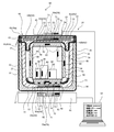
- the inspection system 60 of the vacuum insulation body 10 according to the second embodiment further includes an ID tag 80 and an ID reader 82 in addition to the vacuum insulation body 10, the inspection device 70, and the pedestal 61. There is. As a result, the inspection system 60 can inspect the contents of the heat insulating box 20 in addition to the inspection of the heat insulating performance of the vacuum heat insulating body 10.
- the heat insulating box 20 includes a heat insulating container 30, a heat insulating lid 40, and a heat storage unit 90.
- the heat storage unit 90 has a heat storage container 91, a heat storage lid 92, and a support portion 93.
- the heat storage container 91 has a box shape with an open upper end, and the heat storage lid 92 is attached to the upper end of the heat storage container 91 so that the upper end opening of the heat storage container 91 can be opened and closed. Therefore, it is possible to prevent the heat storage container 91 from being put into the heat insulation box 20 in a state where the heat storage lid 92 is forgotten to be attached to the heat storage container 91.
- the heat storage container 91 and the heat storage lid 92 are provided with an accommodating portion along the surface thereof, and the heat storage material 94 is detachably accommodated in the accommodating portion.
- the heat storage material 94 is a member having a cooling effect or a heat retaining effect.
- the heat storage material 94 surrounds the internal space formed by the heat storage container 91 and the heat storage lid 92, and can cool or keep the internal space warm. Further, a temperature logger T is installed in the heat storage container 91.
- the support portion 93 is formed of, for example, a cushioning material such as Styrofoam, and has a shape along the upper surface of the second lower wall 11 of the first vacuum heat insulating body 10a. As shown in FIG. 1, the heat storage unit 90 is placed in the internal space of the heat insulating box 20 formed by the heat insulating container 30 and the heat insulating lid 40.
- the support portion 93 is arranged on the second lower wall 11 of the first vacuum heat insulating body 10a, and supports the heat storage container 91 with respect to the first vacuum heat insulating body 10a.
- the protruding portion of the lower lid portion 44 of the heat insulating lid 40 fits between the first vacuum heat insulating body 10a and the heat storage container 91, and the heat storage container 91 is supported with respect to the heat insulation container 30.
- the ID tag 80 is attached to the contained items of the vacuum heat insulating body 10, such as the heat storage material 94, the support portion 93, the temperature logger T, and the article M.
- the ID tag 80 is, for example, a passive type IC tag such as an RFID (Radio Frequency Identifier) tag, has a memory, and stores the identification information (contained product ID) of the stored product in the memory.
- the ID reader 82 is, for example, an RFID reader, which has an antenna, is provided on the pedestal 61 alongside the first inspection device 70a, and is connected to the computer 64.
- ⁇ Inspection system inspection method> As shown in FIG. 8, a case where the inspection system 60 inspects the degree of vacuum of the vacuum heat insulating body 10 and inspects the contained items of the vacuum heat insulating body 10 will be described.
- the first inspection device 70a is arranged on the pedestal 61 and the second inspection device 70b is provided on the portable terminal 65 separately from the pedestal 61 will be described.
- the form of the second inspection device 70b is not limited to this, and may be provided on the pedestal 61 together with the first inspection device 70a, for example, as shown in FIG.
- the heat storage material 94 that has been pre-cooled to several ° C. is housed in the storage portion of the heat storage container 91 and the storage portion of the heat storage lid 92, and the temperature logger T is attached to the heat storage container 91 to form the heat storage container 91.
- the article M is stored, and the opening of the heat storage container 91 is closed by the heat storage lid 92.
- the heat storage unit 90 is housed in the heat insulating container 30, and the opening of the heat insulating container 30 is closed by the heat insulating lid 40.
- the heat insulating box 20 is arranged on the first mounting surface 62 so that the first wireless vacuum gauge device 50a faces the first inspection device 70a. Further, the terminal 65 is arranged on the heat insulating lid 40 so that the second wireless vacuum gauge device 50b faces the second inspection device 70b.
- the transmitting unit 52 faces the receiving unit 71
- the power receiving coil 55 of the power supply unit 53 faces the power transmission coil 73 of the power transmission unit 72.
- the computer 64 drives the ID reader 82 and emits radio waves from the ID reader 82.
- the ID tag 80 receives radio waves from the ID reader 82 and transmits the contained item ID of the ID tag 80.
- the ID reader 82 receives the contained item ID and outputs it to the computer 64.
- the computer 64 stores each contained item ID in association with the detection pressure, the transmitting unit ID, and the receiving unit ID in the storage unit, and displays these in the display unit.
- the degree of vacuum of the vacuum insulation body 10 and its inspection location can be obtained from the detection pressure, the transmission unit ID, and the reception unit ID, and the vacuum insulation body 10 and its accommodation are contained from the transmission unit ID and the contained product ID. It is possible to determine the presence or absence of contained items such as the heat storage material 94, the support portion 93, the temperature logger T, and the article M.
- the outer cover material 14 is made of a non-metal, but a part thereof may be made of a metal such as aluminum and stainless steel.
- a region facing at least one of the power receiving coil 55 and the transmitting portion 52 is formed of non-metal, and a part or all of the other region is formed of metal such as metal foil. May be.
- the power receiving coil 55 can receive power from the power transmission coil 73 via the non-metal outer cover material 14, and the transmitting unit 52 communicates with the receiving unit 71 via the non-metal outer cover material 14.
- the degree of vacuum inside the outer cover material 14 can be maintained high by the metal foil in the other regions.
- the outer cover material 14 may have a laminated structure of a non-metal film and a metal vapor deposition film.
- the metal vapor deposition film is interposed between the power receiving coil 55 and the power transmitting coil 73, the power feeding efficiency is somewhat lowered, but the degree of vacuum inside the outer cover material 14 can be maintained high.
- the metal vapor deposition film is not formed in the region of the outer cover material 14 facing at least one of the power receiving coil 55 and the transmitting unit 52, and the metal is partially or wholly covered in the other regions. A vapor-deposited film may be formed.
- the vacuum insulation body 10 was covered with exterior members 31, 41 and protective layers 32, 42.
- the vacuum heat insulating body 10 may not be covered with the exterior members 31, 41 and the protective layers 32, 42, or may be covered with any one of the exterior members 31, 41 and the protective layers 32, 42. good.
- the power transmission unit 72 and the reception unit 71 are arranged side by side, but the arrangement thereof is not limited to this.
- the narrower the distance between the power transmission coil 73 of the power transmission unit 72 and the power reception coil 55 of the power supply unit 53 the higher the power transmission efficiency. Therefore, the power transmission unit 72 so that the power transmission coil 73 and the power reception coil 55 correspond to each other. It is preferable to arrange.
- the reception unit 71 can communicate with the transmission unit 52 at a distant position. Therefore, the power transmission unit 72 may be arranged so that the power transmission coil 73 corresponds to the power reception coil 55, and the reception unit 71 may be arranged at a position away from the position corresponding to the transmission unit 52.
- the first modification is applied to any one of the second embodiment and the first to third modifications
- the second modification is applied to the second embodiment and the fourth modification
- the third modification is applied to the second embodiment and the second modification. 4
- the modified example 4 may be applied to the second embodiment.
- the vacuum insulation body and this inspection system of the present disclosure are useful as a vacuum insulation body and this inspection system that can safely inspect the heat insulation performance in a short time.
- Vacuum insulation body 10a First vacuum insulation body (vacuum insulation body) 10b: Second vacuum insulation body (vacuum insulation body) 13: Core material 14: Outer cover material 51: Pressure sensor 52: Transmission unit 53: Power supply unit 55: Power receiving coil 60: Inspection system 70: Inspection device 70a: First inspection device (inspection device) 70b: Second inspection device (inspection device) 71: Receiver 72: Power transmission 73: Power transmission coil
Abstract
A vacuum heat insulator (10) comprising: a core material (13); a pressure sensor (51) that detects pressure; a transmission unit (52) that, via wireless communication, transmits the pressure detected by the pressure sensor (51); an electric power supply unit (53) that supplies electric power to the pressure sensor (51) and the transmission unit (52); and an outer material (14) that has gas barrier properties and accommodates the core material (13), the pressure sensor (51), the transmission unit (52), and the electric power supply unit (53), the interior of the outer material (14) being depressurized.
Description
本開示は、真空断熱体及びこの検査システムに関する。
This disclosure relates to vacuum insulation and this inspection system.
従来の真空断熱体として、特許文献1の断熱容器が知られている。この断熱容器は、容器、及び、容器を収容する断熱性のバッグを備えている。バッグは二重壁を有しており、二重壁の間に真空断熱材が収容されている。
As a conventional vacuum heat insulating body, the heat insulating container of Patent Document 1 is known. The heat insulating container includes a container and a heat insulating bag for accommodating the container. The bag has a double wall, and the vacuum heat insulating material is housed between the double walls.
例えば、医薬品等の輸送には、外気温に係わらず所定時間、低温で維持する厳しい温度管理が求められる。これに対し、上記のような真空断熱材は、外力及び経年劣化等により真空度が低くなり、断熱性能が低下することがある。このため、真空断熱材の断熱性能を検査することが重要になっている。
For example, the transportation of pharmaceuticals and the like requires strict temperature control to maintain a low temperature for a predetermined time regardless of the outside temperature. On the other hand, the vacuum heat insulating material as described above may have a low degree of vacuum due to external force, deterioration over time, etc., and the heat insulating performance may be lowered. Therefore, it is important to inspect the heat insulating performance of the vacuum heat insulating material.
しかしながら、この断熱性能の検査に熱流束センサ及び温度センサ等の検査器を用いると、真空断熱材に検査器を接触させる必要があるため、真空断熱体を破損するおそれがある。また、検査器による熱量又は温度等の測定には時間がかかり、断熱性能の検査時間が長くなってしまう。
However, if an inspection device such as a heat flux sensor or a temperature sensor is used to inspect the heat insulation performance, the vacuum heat insulating material may be damaged because the test device needs to be brought into contact with the vacuum heat insulating material. In addition, it takes time to measure the amount of heat or temperature by the inspection device, and the inspection time for heat insulation performance becomes long.
本開示はこのような課題を解決するためになされたものであり、短時間で安全に断熱性能を検査することができる真空断熱体及びこの検査システムを提供することを目的としている。
The present disclosure has been made to solve such a problem, and an object of the present invention is to provide a vacuum heat insulating body capable of safely inspecting the heat insulating performance in a short time and this inspection system.
本発明の第1態様に係る真空断熱体は、芯材と、圧力を検出する圧力センサと、前記圧力センサによる検出圧力を無線通信により送信する送信部と、前記圧力センサ及び前記送信部に電力を供給する電力供給部と、前記芯材、前記圧力センサ、前記送信部及び前記電力供給部を収容した内部が減圧されたガスバリア性を有する外被材と、を備えている。
The vacuum heat insulating body according to the first aspect of the present invention includes a core material, a pressure sensor that detects pressure, a transmission unit that transmits the pressure detected by the pressure sensor by wireless communication, and power to the pressure sensor and the transmission unit. A core material, a pressure sensor, a transmission unit, and an outer cover material having a gas barrier property in which the inside containing the power supply unit is decompressed are provided.
この構成によれば、圧力センサにより外被材内の圧力を検出し、この検出圧力を送信部により無線通信で送信している。この圧力は短時間で検出することができ、また、外被材に非接触で検出圧力を得ることができるため、検出圧力に基づいて真空断熱体の断熱性能を短時間で安全に検査することができる。
According to this configuration, the pressure inside the outer cover material is detected by the pressure sensor, and this detected pressure is transmitted by wireless communication by the transmission unit. Since this pressure can be detected in a short time and the detected pressure can be obtained without contacting the outer cover material, the heat insulating performance of the vacuum insulator can be safely inspected in a short time based on the detected pressure. Can be done.
本発明の第2態様に係る真空断熱体では、第1態様において、前記送信部は、NFC(Near Field Communication)により前記検出圧力を送信してもよい。この構成によれば、受信部は、ペアリングすることなく検出圧力を送信部から受信することができ、検出圧力に基づいて真空断熱体の断熱性能を短時間で検査することができる。
In the vacuum insulation body according to the second aspect of the present invention, in the first aspect, the transmission unit may transmit the detection pressure by NFC (Near Field Communication). According to this configuration, the receiving unit can receive the detected pressure from the transmitting unit without pairing, and can inspect the heat insulating performance of the vacuum heat insulating body in a short time based on the detected pressure.
本発明の第3態様に係る真空断熱体では、第1態様において、前記送信部は、BLE(Bluetooth(登録商標) low energy)通信により前記検出圧力を送信してもよい。この構成によれば、受信部は、離れて配置された送信部からの検出圧力を受信することができ、受信部の配置の自由度が増す。
In the vacuum insulation body according to the third aspect of the present invention, in the first aspect, the transmission unit may transmit the detection pressure by BLE (Bluetooth Low Energy) communication. According to this configuration, the receiving unit can receive the detection pressure from the transmitting unit arranged apart from each other, and the degree of freedom in arranging the receiving unit is increased.
本発明の第4態様に係る真空断熱体では、第1~3態様のいずれかにおいて、前記電力供給部は、前記外被材外の送電コイルから無接触受電する受電コイルを含んでいてもよい。この構成によれば、電力供給部にバッテリを用いないことにより、電力不足による検査不能、及び、バッテリの液漏れによる真空度の低下を防止することができる。
In the vacuum insulation body according to the fourth aspect of the present invention, in any one of the first to third aspects, the power supply unit may include a power receiving coil that receives non-contact power from the power transmitting coil outside the outer cover material. .. According to this configuration, by not using the battery for the power supply unit, it is possible to prevent the inspectability due to insufficient power and the decrease in the degree of vacuum due to the liquid leakage of the battery.
本発明の第5態様に係る真空断熱体では、第4態様において、前記受電コイルは、磁界共鳴方式により受電してもよい。この構成によれば、受電コイルは、離れて配置された送電コイルから受電することができ、厚みが大きい保護層等により真空断熱体が覆われた状態であっても、保護層を真空断熱体から取り外さずに、真空断熱体の断熱性能の検査することができる。
In the vacuum insulation body according to the fifth aspect of the present invention, in the fourth aspect, the power receiving coil may receive power by a magnetic field resonance method. According to this configuration, the power receiving coil can receive power from the power transmission coils arranged apart from each other, and even if the vacuum heat insulating body is covered with a thick protective layer or the like, the protective layer is a vacuum heat insulating body. The insulation performance of the vacuum insulation can be inspected without removing it from.
本発明の第6態様に係る真空断熱体では、第4態様において、前記受電コイルは、電磁誘導方式により受電してもよい。この構成によれば、電力供給部を小型化できるため、真空断熱体の大型化を抑えながら、電力供給部に起因した断熱性能の低下を低減することができる。
In the vacuum insulation body according to the sixth aspect of the present invention, in the fourth aspect, the power receiving coil may receive power by an electromagnetic induction method. According to this configuration, since the power supply unit can be miniaturized, it is possible to reduce the deterioration of the heat insulation performance due to the power supply unit while suppressing the increase in size of the vacuum heat insulating body.
本発明の第7態様に係る真空断熱体では、第1~3態様のいずれかにおいて、前記電力供給部は、前記電力を蓄えているバッテリを含んでいてもよい。この構成によれば、電力供給部を小型化できるため、真空断熱体の大型化を抑えながら、電力供給部に起因した断熱性能の低下を低減することができる。
In the vacuum insulation body according to the seventh aspect of the present invention, in any one of the first to third aspects, the power supply unit may include a battery storing the power. According to this configuration, since the power supply unit can be miniaturized, it is possible to reduce the deterioration of the heat insulation performance due to the power supply unit while suppressing the increase in size of the vacuum heat insulating body.
本発明の第8態様に係る真空断熱体の検査システムは、第1~6態様のいずれかの真空断熱体と、前記電力供給部に前記電力を送電する送電部、及び、前記送信部により送信された前記検出圧力を受信する受信部を有する検査装置と、を備えていてもよい。この構成によれば、真空断熱体の断熱性能を短時間で安全に検査することができる。
The inspection system for the vacuum insulation body according to the eighth aspect of the present invention is transmitted by the vacuum insulation body according to any one of the first to sixth aspects, the power transmission unit that transmits the electric power to the power supply unit, and the transmission unit. An inspection device having a receiving unit for receiving the detected pressure may be provided. According to this configuration, the heat insulating performance of the vacuum heat insulating body can be safely inspected in a short time.
本発明の第9態様に係る真空断熱体の検査システムは、第7態様の真空断熱体と、前記送信部により送信された前記検出圧力を受信する受信部を有する検査装置と、を備えている。この構成によれば、真空断熱体の断熱性能を短時間で安全に検査することができる。
The vacuum insulation body inspection system according to the ninth aspect of the present invention includes the vacuum insulation body of the seventh aspect and an inspection device having a receiving unit for receiving the detection pressure transmitted by the transmitting unit. .. According to this configuration, the heat insulating performance of the vacuum heat insulating body can be safely inspected in a short time.
本開示は、真空断熱体及びこの検査システムにおいて、短時間で安全に断熱性能を検査することができるという効果を奏する。
The present disclosure has the effect that the heat insulating performance can be safely inspected in a short time in the vacuum heat insulating body and this inspection system.
本開示の上記目的、他の目的、特徴、及び利点は、添付図面参照の下、以下の好適な実施態様の詳細な説明から明らかにされる。
The above objectives, other objectives, features, and advantages of the present disclosure will be apparent from the following detailed description of preferred embodiments with reference to the accompanying drawings.
以下、本開示の実施の形態を、図面を参照しながら具体的に説明する。なお、以下では全ての図面を通じて同一又は相当する要素には同一の参照符号を付して、その重複する説明を省略する。
Hereinafter, embodiments of the present disclosure will be specifically described with reference to the drawings. In the following, the same or corresponding elements will be designated by the same reference numerals throughout the drawings, and duplicate description thereof will be omitted.
(実施の形態1)
<保温箱の構成>
実施の形態1に係る真空断熱体10は、図1及び図2に示すように、例えば、医薬品、検体、食品等の物品を輸送したり保管したりするための保温箱20に用いられる。以下では、真空断熱体10を保温箱20に用いる場合について説明するが、真空断熱体10の用途はこれに限定されない。 (Embodiment 1)
<Structure of heat insulation box>
As shown in FIGS. 1 and 2, thevacuum insulation body 10 according to the first embodiment is used as a heat insulating box 20 for transporting or storing articles such as pharmaceuticals, specimens, and foods, for example. Hereinafter, the case where the vacuum heat insulating body 10 is used for the heat insulating box 20 will be described, but the use of the vacuum heat insulating body 10 is not limited to this.
<保温箱の構成>
実施の形態1に係る真空断熱体10は、図1及び図2に示すように、例えば、医薬品、検体、食品等の物品を輸送したり保管したりするための保温箱20に用いられる。以下では、真空断熱体10を保温箱20に用いる場合について説明するが、真空断熱体10の用途はこれに限定されない。 (Embodiment 1)
<Structure of heat insulation box>
As shown in FIGS. 1 and 2, the
保温箱20は保温容器30及び保温蓋40を備えている。保温容器30は第1外装部材31、第1保護層32及び第1真空断熱体10aを有し、保温蓋40は第2外装部材41、被覆層45、第2保護層42及び第2真空断熱体10bを有している。なお、第1真空断熱体10a及び第2真空断熱体10bを単に真空断熱体10と称することがある。この真空断熱体10の詳細については後述する。
The heat insulating box 20 includes a heat insulating container 30 and a heat insulating lid 40. The heat insulating container 30 has a first exterior member 31, a first protective layer 32 and a first vacuum heat insulating body 10a, and the heat insulating lid 40 has a second exterior member 41, a covering layer 45, a second protective layer 42 and a second vacuum heat insulating body. It has a body 10b. The first vacuum heat insulating body 10a and the second vacuum heat insulating body 10b may be simply referred to as the vacuum heat insulating body 10. The details of the vacuum heat insulating body 10 will be described later.
第1外装部材31内に第1保護層32が配置され、第1保護層32内に第1真空断熱体10aが配置され、第1真空断熱体10aはその内側に内部空間を有し、この内部空間の開口を保温蓋40が覆って、保温箱20が閉じられる。この保温箱20において、第1外装部材31よりも第1真空断熱体10aの内部空間側を内側と称し、その反対側を外側と称する。また、保温蓋40が保温容器30の開口を塞いだ状態において保温蓋40よりも保温容器30側を下側と称し、その反対側を上側と称するが、保温箱20の配置はこれに限定されない。
The first protective layer 32 is arranged in the first exterior member 31, the first vacuum heat insulating body 10a is arranged in the first protective layer 32, and the first vacuum heat insulating body 10a has an internal space inside the first protective layer 32. The heat insulating lid 40 covers the opening of the internal space, and the heat insulating box 20 is closed. In the heat insulating box 20, the internal space side of the first vacuum heat insulating body 10a with respect to the first exterior member 31 is referred to as the inside, and the opposite side thereof is referred to as the outside. Further, in a state where the heat insulating lid 40 closes the opening of the heat insulating container 30, the side of the heat insulating container 30 is referred to as the lower side and the opposite side is referred to as the upper side, but the arrangement of the heat insulating box 20 is not limited to this. ..
保温容器30の第1外装部材31は、上端が開口した箱形状を有しており、例えば、合成繊維の生地、プラスチック、段ボール等の材料で形成されている。第1外装部材31は、その内部に第1保護層32を収容し、第1保護層32の外表面を覆っている。なお、ユーザが保温箱20を持ち易いように、第1外装部材31には手提げベルト等が取り付けられていてもよい。
The first exterior member 31 of the heat insulating container 30 has a box shape with an open upper end, and is made of, for example, a synthetic fiber fabric, plastic, corrugated cardboard, or the like. The first exterior member 31 accommodates the first protective layer 32 inside and covers the outer surface of the first protective layer 32. A hand-carrying belt or the like may be attached to the first exterior member 31 so that the user can easily hold the heat insulating box 20.
第1保護層32は、例えば、上端が開口した箱形状を有しており、例えば、発泡スチロール等の緩衝材により形成されている。第1保護層32は、その内部に第1真空断熱体10aを収容し、第1真空断熱体10aの外表面を覆い、外部からの衝撃及び振動等から第1真空断熱体10a及び物品の破損を防いでいる。
The first protective layer 32 has, for example, a box shape with an open upper end, and is formed of, for example, a cushioning material such as Styrofoam. The first protective layer 32 accommodates the first vacuum heat insulating body 10a inside, covers the outer surface of the first vacuum heat insulating body 10a, and damages the first vacuum heat insulating body 10a and the article due to external impact and vibration. Is prevented.
第1保護層32は、第1下壁33及び4つの第1側壁34を有しており、これらは矩形の平板形状である。第1下壁33は第1保護層32の下端に配置されている。4つの第1側壁34は第1下壁33の外周縁から上方に立ち上り、互いに隣接する第1側壁34どうしが接続されており、下端開口が第1側壁34により塞がれた角筒形状を有している。
The first protective layer 32 has a first lower wall 33 and four first side walls 34, which have a rectangular flat plate shape. The first lower wall 33 is arranged at the lower end of the first protective layer 32. The four first side walls 34 rise upward from the outer peripheral edge of the first lower wall 33, and the first side walls 34 adjacent to each other are connected to each other, and the lower end opening is closed by the first side wall 34 in a square tube shape. Have.
第1真空断熱体10aは、上端が開口した箱形状であって、第2下壁11及び4つの第2側壁12を有している。第2下壁11及び第2側壁12は矩形の平板形状であり、第2下壁11は第1真空断熱体10aの下端に配置されている。
例えば、4つの第2側壁12は第2下壁11の外周縁から上方に立ち上り、互いに隣接する第2側壁12どうしが接続されており、下端開口が第2下壁11により塞がれた角筒形状を有している。 The first vacuumheat insulating body 10a has a box shape with an open upper end, and has a second lower wall 11 and four second side walls 12. The second lower wall 11 and the second side wall 12 have a rectangular flat plate shape, and the second lower wall 11 is arranged at the lower end of the first vacuum heat insulating body 10a.
For example, the foursecond side walls 12 rise upward from the outer peripheral edge of the second lower wall 11, and the second side walls 12 adjacent to each other are connected to each other, and the lower end opening is closed by the second lower wall 11. It has a tubular shape.
例えば、4つの第2側壁12は第2下壁11の外周縁から上方に立ち上り、互いに隣接する第2側壁12どうしが接続されており、下端開口が第2下壁11により塞がれた角筒形状を有している。 The first vacuum
For example, the four
このように、保温容器30の外表面は第1外装部材31により形成されており、保温容器30の内表面は第1真空断熱体10aにより形成されており、保温容器30の上端開口は第1真空断熱体10aの上端開口に相当する。保温容器30の内部空間は第1真空断熱体10aの内部空間に相当し、この内部空間は、第2下壁11及び4つの第2側壁12により囲まれた直方体形状であって上端開口を介して外部に連通している。
As described above, the outer surface of the heat insulating container 30 is formed by the first exterior member 31, the inner surface of the heat insulating container 30 is formed by the first vacuum heat insulating body 10a, and the upper end opening of the heat insulating container 30 is the first. Corresponds to the upper end opening of the vacuum insulation body 10a. The internal space of the heat insulating container 30 corresponds to the internal space of the first vacuum heat insulating body 10a, and this internal space has a rectangular parallelepiped shape surrounded by the second lower wall 11 and the four second side walls 12 through the upper end opening. It communicates with the outside.
保温蓋40は、上側蓋部分43及び下側蓋部分44を有している。上側蓋部分43は、矩形の平板形状を有している。下側蓋部分44は、矩形の平板形状の平板部分、及び、この平板部分の下面から突出した突出部分を有している。下側蓋部分44の平板部分は、保温容器30の上端開口に対向する下面、及び、下面と反対側の上面を有している。この下側蓋部分44の上面は上側蓋部分43の下面に対向して接触することにより、保温蓋40が形成される。
The heat insulating lid 40 has an upper lid portion 43 and a lower lid portion 44. The upper lid portion 43 has a rectangular flat plate shape. The lower lid portion 44 has a rectangular flat plate-shaped flat plate portion and a protruding portion protruding from the lower surface of the flat plate portion. The flat plate portion of the lower lid portion 44 has a lower surface facing the upper end opening of the heat insulating container 30 and an upper surface opposite to the lower surface. The upper surface of the lower lid portion 44 is in contact with the lower surface of the upper lid portion 43 so as to face the lower surface of the upper lid portion 43, whereby the heat insulating lid 40 is formed.
図1に示すように、保温蓋40が保温容器30の上端開口を塞いだ状態では、下側蓋部分44の下面が第1保護層32の上端及び第1真空断熱体10aの上端に当接する。また、下側蓋部分44の突出部分が第1真空断熱体10aの内側に嵌り、下側蓋部分44の外周面が第1真空断熱体10aの内面に当接又は隙間を空けて近接している。
As shown in FIG. 1, when the heat insulating lid 40 closes the upper end opening of the heat insulating container 30, the lower surface of the lower lid portion 44 comes into contact with the upper end of the first protective layer 32 and the upper end of the first vacuum heat insulating body 10a. .. Further, the protruding portion of the lower lid portion 44 fits inside the first vacuum heat insulating body 10a, and the outer peripheral surface of the lower lid portion 44 abuts or approaches the inner surface of the first vacuum heat insulating body 10a with a gap. There is.
このような保温蓋40において、上側蓋部分43は第2外装部材41、被覆層45の上側部分45a及び第2保護層42の上側部分42aにより形成されており、下側蓋部分44は被覆層45の下側部分45b、第2保護層42の下側部分42b、及び、第2真空断熱体10bにより形成されている。
In such a heat insulating lid 40, the upper lid portion 43 is formed by the second exterior member 41, the upper portion 45a of the coating layer 45, and the upper portion 42a of the second protective layer 42, and the lower lid portion 44 is the coating layer. It is formed by the lower portion 45b of the 45, the lower portion 42b of the second protective layer 42, and the second vacuum heat insulating body 10b.
第2外装部材41は、例えば、合成繊維の生地、プラスチック、段ボール等の材料で形成されている。第2保護層42は、発泡スチロール等の緩衝材によって形成されている。被覆層45は、第1保護層32及び第2保護層42と同様に発泡スチロール等の緩衝材によって形成されてもよいし、保温容器30の上端開口の密閉性を高めるために軟質発泡ウレタン等の緩衝材によって形成されてもよい。
The second exterior member 41 is made of, for example, a synthetic fiber fabric, plastic, corrugated cardboard, or other material. The second protective layer 42 is formed of a cushioning material such as Styrofoam. The coating layer 45 may be formed of a cushioning material such as styrofoam like the first protective layer 32 and the second protective layer 42, or may be made of soft urethane foam or the like in order to enhance the airtightness of the upper end opening of the heat insulating container 30. It may be formed by a cushioning material.
なお、被覆層45の上側部分45aと第2保護層42の上側部分42aとが、双方発泡スチロール等の同材質の場合は一体的に形成されていてもよい。また、同様に、被覆層45の下側部分45bと第2保護層42の下側部分42bとが、双方発泡スチロール等の同材質の場合は一体的に形成されていてもよい。
Note that the upper portion 45a of the coating layer 45 and the upper portion 42a of the second protective layer 42 may be integrally formed when both are made of the same material such as Styrofoam. Similarly, the lower portion 45b of the coating layer 45 and the lower portion 42b of the second protective layer 42 may be integrally formed when both are made of the same material such as Styrofoam.
上側部分42aは、その上面及び側面が上側部分45aにより覆われており、上側部分45aが第2外装部材41により覆われている。このため、上側蓋部分43の上面及び側面は第2外装部材41により構成され、上側蓋部分43の下面は上側部分42aにより構成されている。また、下側部分42bは、上面以外の面が下側部分45bにより覆われている。このため、下側蓋部分44における平板部分の下面及び側面、並びに突出部分は下側部分45bにより構成され、下側蓋部分44の上面は下側部分42bにより構成されている。
The upper surface and side surfaces of the upper portion 42a are covered with the upper portion 45a, and the upper portion 45a is covered with the second exterior member 41. Therefore, the upper surface and the side surface of the upper lid portion 43 are composed of the second exterior member 41, and the lower surface of the upper lid portion 43 is composed of the upper portion 42a. Further, the lower portion 42b is covered with a surface other than the upper surface by the lower portion 45b. Therefore, the lower surface and side surfaces of the flat plate portion and the protruding portion of the lower lid portion 44 are composed of the lower portion 45b, and the upper surface of the lower lid portion 44 is composed of the lower portion 42b.
下側部分42bは、その上面から窪む窪みが設けられており、その窪みに第2真空断熱体10bが収容されている。第2真空断熱体10bの上面と下側部分42bの上面とは、面一になるように配置されている。第2真空断熱体10bの上面及び下側部分42bの上面が上側部分42aにより覆われると、上側蓋部分43及び下側蓋部分44が接続されて、保温蓋40が形成される。このため、上側部分45a及び下側部分45bにより形成された被覆層45内に、上側部分42a及び下側部分42bにより形成された第2保護層42が収容され、この第2保護層42内に第2真空断熱体10bが配置される。この保温蓋40において上面及び側面は第2外装部材41により構成されており、下面及び突出部分は被覆層45により構成される。この保温蓋40内に第2真空断熱体10bが配置され、第2保護層42により覆われる。なお、第2外装部材41は、保温蓋40が保温容器30の上端開口を開閉可能に第1外装部材31の上端に接続されていてもよい。
The lower portion 42b is provided with a recess that is recessed from the upper surface thereof, and the second vacuum heat insulating body 10b is housed in the recess. The upper surface of the second vacuum heat insulating body 10b and the upper surface of the lower portion 42b are arranged so as to be flush with each other. When the upper surface of the second vacuum heat insulating body 10b and the upper surface of the lower portion 42b are covered with the upper portion 42a, the upper lid portion 43 and the lower lid portion 44 are connected to form the heat insulating lid 40. Therefore, the second protective layer 42 formed by the upper portion 42a and the lower portion 42b is housed in the coating layer 45 formed by the upper portion 45a and the lower portion 45b, and the second protective layer 42 formed by the upper portion 42a and the lower portion 42b is housed in the second protective layer 42. The second vacuum insulation body 10b is arranged. In the heat insulating lid 40, the upper surface and the side surface are composed of the second exterior member 41, and the lower surface and the protruding portion are composed of the covering layer 45. The second vacuum heat insulating body 10b is arranged in the heat insulating lid 40 and is covered with the second protective layer 42. The second exterior member 41 may be connected to the upper end of the first exterior member 31 so that the heat insulating lid 40 can open and close the upper end opening of the heat insulating container 30.
<真空断熱体の構成>
真空断熱体10は、図1及び図3に示すように、芯材13、外被材14及び無線真空計デバイス50を備えている。無線真空計デバイス50は圧力センサ51、送信部52、電力供給部53及び筐体54を有している。 <Construction of vacuum insulation>
As shown in FIGS. 1 and 3, the vacuumheat insulating body 10 includes a core material 13, an outer cover material 14, and a wireless vacuum gauge device 50. The wireless vacuum gauge device 50 includes a pressure sensor 51, a transmission unit 52, a power supply unit 53, and a housing 54.
真空断熱体10は、図1及び図3に示すように、芯材13、外被材14及び無線真空計デバイス50を備えている。無線真空計デバイス50は圧力センサ51、送信部52、電力供給部53及び筐体54を有している。 <Construction of vacuum insulation>
As shown in FIGS. 1 and 3, the vacuum
芯材13は、多孔質体であって、熱伝導性が低い材料により形成されており、真空断熱材の骨格となり断熱空間を形成する。芯材13には、例えば、連続気泡ウレタンフォーム等の連続気泡体、発泡スチロール等の発泡樹脂材、繊維の集合体、及び、無機微粒子の集合体が用いられる。連続気泡ウレタンフォームは、複数の気泡が互いに連通した連続気泡を有するポリウレタンフォームである。
The core material 13 is a porous body and is formed of a material having low thermal conductivity, and serves as a skeleton of the vacuum heat insulating material to form a heat insulating space. For the core material 13, for example, an open cell such as open cell urethane foam, a foamed resin material such as expanded polystyrene, an aggregate of fibers, and an aggregate of inorganic fine particles are used. The open cell urethane foam is a polyurethane foam having open cells in which a plurality of bubbles communicate with each other.
外被材14は、樹脂等の非金属材料により形成されており、ガスバリア性を有し、真空断熱体10の内部の圧力を低く維持する。例えば、外被材14は、熱溶着可能な熱可塑性樹脂層、及び、エチレン-ビニルアルコール共重合体(EVOH)又はポリビニルアルコール重合体等の空気バリア層、及び、ポリプロピレン等の水蒸気バリア層の積層構造を有していてもよい。外被材14は、その内部に芯材13及び無線真空計デバイス50を収容し、これらを覆っている。なお、これに加えて、気体吸着材が外被材14内に収容されていてもよい。気体吸着材は、外被材14の内部に残存又は侵入する水蒸気及び空気等のガスを吸着する。これにより、外被材14の内部の圧力を低く維持することができる。
The outer cover material 14 is formed of a non-metal material such as resin, has a gas barrier property, and keeps the pressure inside the vacuum heat insulating body 10 low. For example, the outer cover material 14 is a laminate of a heat-weldable thermoplastic resin layer, an air barrier layer such as an ethylene-vinyl alcohol copolymer (EVOH) or a polyvinyl alcohol polymer, and a water vapor barrier layer such as polypropylene. It may have a structure. The outer cover material 14 accommodates the core material 13 and the wireless vacuum gauge device 50, and covers them. In addition to this, the gas adsorbent may be housed in the outer cover material 14. The gas adsorbent adsorbs gases such as water vapor and air that remain or invade inside the outer cover material 14. As a result, the pressure inside the outer cover material 14 can be kept low.
圧力センサ51は、外被材14の内部の圧力(気圧)を検出するセンサであり、送信部52に電気的に接続されており、検出圧力を送信部52に出力する。圧力センサ51には、例えば、ヒータ及び熱電対を備え、ヒータを加熱したときに熱電対で検出される温度から、周囲の熱伝導特性を測定することで気圧(真空度)を測定するものが用いられる。しかしながら、圧力センサ51は、これに限定されず、例えば、ピエゾ式、静電容量式及び振動式等の微小電気機械システム(MEMS)が用いられる。
The pressure sensor 51 is a sensor that detects the pressure (atmospheric pressure) inside the outer cover material 14, is electrically connected to the transmission unit 52, and outputs the detected pressure to the transmission unit 52. The pressure sensor 51 is provided with, for example, a heater and a thermocouple, and measures the atmospheric pressure (degree of vacuum) by measuring the heat conduction characteristics of the surroundings from the temperature detected by the thermocouple when the heater is heated. Used. However, the pressure sensor 51 is not limited to this, and for example, a microelectromechanical system (MEMS) such as a piezo type, a capacitance type, and a vibration type is used.
送信部52は、圧力センサ51による検出圧力を無線通信により送信する素子であり、例えば、通信制御IC、メモリ及びアンテナを有している。送信部52は自己の識別情報(送信部ID)をメモリに記憶しており、通信制御ICは検出圧力と共に送信部IDをアンテナから送信する。例えば、送信部52は、13.56MHz帯の周波数を使った近距離無線通信であって、NFC(Near Field Communication)により検出圧力を送信する。これにより、送信部52は、所定の距離内(例えば、10cm以内)の受信部に近接することにより、検出圧力を受信することができる。
The transmission unit 52 is an element that transmits the pressure detected by the pressure sensor 51 by wireless communication, and has, for example, a communication control IC, a memory, and an antenna. The transmission unit 52 stores its own identification information (transmission unit ID) in a memory, and the communication control IC transmits the transmission unit ID together with the detection pressure from the antenna. For example, the transmission unit 52 is a short-range wireless communication using a frequency in the 13.56 MHz band, and transmits the detection pressure by NFC (Near Field Communication). As a result, the transmitting unit 52 can receive the detected pressure by approaching the receiving unit within a predetermined distance (for example, within 10 cm).
電力供給部53は、圧力センサ51及び送信部52に電気的に接続されており、これらに電力を供給する。例えば、電力供給部53は、給電制御IC、及び、磁界共鳴方式のワイヤレス給電の受電部を有している。受電部は、外被材14外の1次側コイル(送電コイル)から無接触受電する2次側コイル(受電コイル55)を含んでいる。受電コイル55は、中心軸の周囲を導線が巻き回されたコイルであって、例えば、ソレノイド型コイル又はスパイラル型コイルである。受電コイル55は送電コイルから伝送された電力を受け、給電制御ICはこの電力を圧力センサ51及び送信部52に供給する。このように、圧力センサ51及び送信部52への電力供給にバッテリを用いないことにより、減圧状態によるバッテリの液漏れがなく、液漏れによる真空断熱体10の真空度の低下及び電力供給ができない事態を抑制することができる。
The power supply unit 53 is electrically connected to the pressure sensor 51 and the transmission unit 52, and supplies electric power to these. For example, the power supply unit 53 has a power supply control IC and a magnetic field resonance type wireless power supply power receiving unit. The power receiving unit includes a secondary coil (power receiving coil 55) that receives non-contact power from the primary coil (power transmission coil) outside the outer cover material 14. The power receiving coil 55 is a coil in which a conducting wire is wound around a central axis, and is, for example, a solenoid type coil or a spiral type coil. The power receiving coil 55 receives the electric power transmitted from the power transmitting coil, and the power supply control IC supplies this electric power to the pressure sensor 51 and the transmitting unit 52. As described above, since the battery is not used to supply power to the pressure sensor 51 and the transmission unit 52, there is no liquid leakage of the battery due to the reduced pressure state, and the vacuum degree of the vacuum insulation body 10 cannot be lowered and power cannot be supplied due to the liquid leakage. The situation can be suppressed.
筐体54は、樹脂などの非金属により形成されており、その内部に圧力センサ51、送信部52及び電力供給部53を収容し、外被材14内に配置されている。筐体54は内部空間を有し、筐体54には複数の貫通孔56が設けられている。この貫通孔56を介して筐体54内の空気が排出されるため、外被材14内において筐体54内外の圧力は均等になっている。また、筐体54内の空間は、回路部品の保護ために樹脂によりポッティングされていてもよい。この場合も、圧力センサ51及び貫通孔56は樹脂で埋められずに、圧力センサ51により検出される筐体54内の圧力と筐体54外の圧力とは均等にされる。
The housing 54 is made of a non-metal such as resin, and houses the pressure sensor 51, the transmission unit 52, and the power supply unit 53 inside the housing 54, and is arranged in the outer cover material 14. The housing 54 has an internal space, and the housing 54 is provided with a plurality of through holes 56. Since the air inside the housing 54 is discharged through the through hole 56, the pressure inside and outside the housing 54 is even inside the outer cover material 14. Further, the space inside the housing 54 may be potted with resin to protect the circuit components. Also in this case, the pressure sensor 51 and the through hole 56 are not filled with the resin, and the pressure inside the housing 54 detected by the pressure sensor 51 and the pressure outside the housing 54 are equalized.
筐体54は、例えば、平板形状を有しており、互いに対向する一対の壁及びこれらを接続する4つの壁を有している。一対の壁の一方の壁(固定壁57)は、平らであって、圧力センサ51、送信部52及び電力供給部53が並んで取り付けられている。このため、並ぶ方向に直交する方向において、一対の壁間の寸法(筐体54の厚み)を小さくすることができる。これにより、真空断熱体10の厚みを大きくすることなく、無線真空計デバイス50の筐体54に重なる芯材13の厚みを大きく採ることができ、無線真空計デバイス50による断熱性能の低下を抑制することができる。なお、無線真空計デバイス50は、筐体54の一部又は全部を有していなくてもよい。例えば、無線真空計デバイス50において、保護が必要な回路部品を樹脂でポッティングすることによって、回路基板が樹脂により覆われる。これにより、無線真空計デバイス50は、筐体54を用いない、又は、圧力センサ51、送信部52及び電力供給部53の少なくとも一部を収容するような筐体54を用いることができるため、無線真空計デバイス50の厚みを更に薄くすることが可能である。
The housing 54 has, for example, a flat plate shape, and has a pair of walls facing each other and four walls connecting them. One wall (fixed wall 57) of the pair of walls is flat, and the pressure sensor 51, the transmission unit 52, and the power supply unit 53 are mounted side by side. Therefore, the dimension between the pair of walls (thickness of the housing 54) can be reduced in the direction orthogonal to the line-up direction. As a result, the thickness of the core material 13 overlapping the housing 54 of the wireless pressure gauge device 50 can be increased without increasing the thickness of the vacuum heat insulating body 10, and the deterioration of the heat insulating performance due to the wireless pressure gauge device 50 can be suppressed. can do. The wireless pressure gauge device 50 may not have a part or all of the housing 54. For example, in the wireless vacuum gauge device 50, the circuit board is covered with the resin by potting the circuit parts requiring protection with the resin. As a result, the wireless vacuum gauge device 50 does not use the housing 54, or can use the housing 54 that accommodates at least a part of the pressure sensor 51, the transmission unit 52, and the power supply unit 53. The thickness of the wireless vacuum gauge device 50 can be further reduced.
第1真空断熱体10aにおいて、芯材13の下面から窪む窪みが設けられており、この窪みに無線真空計デバイス50(第1無線真空計デバイス50a)が配置されている。第1無線真空計デバイス50aの固定壁57と芯材13の下面とが、互いに面一になるように配置され、外被材14により覆われて、第1無線真空計デバイス50aが第1真空断熱体10a内に配置されている。この際、固定壁57に直交する方向に電力供給部53の受電コイル55の中心軸が延びるように受電コイル55が固定壁57に平行に対向して取り付けられているため、受電コイル55は第1真空断熱体10aの下面に平行に配置される。
In the first vacuum heat insulating body 10a, a recess recessed from the lower surface of the core material 13 is provided, and the wireless vacuum gauge device 50 (first wireless vacuum gauge device 50a) is arranged in this recess. The fixed wall 57 of the first radio pressure gauge device 50a and the lower surface of the core material 13 are arranged so as to be flush with each other and covered with the outer cover material 14, so that the first radio pressure gauge device 50a is in the first vacuum. It is arranged in the heat insulating body 10a. At this time, since the power receiving coil 55 is attached so as to extend the central axis of the power receiving coil 55 of the power supply unit 53 in the direction orthogonal to the fixed wall 57 in parallel with the fixed wall 57, the power receiving coil 55 is the first. 1 It is arranged parallel to the lower surface of the vacuum insulation body 10a.
第2真空断熱体10bにおいて、芯材13の上面から窪む窪みが設けられており、この窪みに無線真空計デバイス50(第2無線真空計デバイス50b)が配置されている。第2無線真空計デバイス50bの固定壁57と芯材13の上面とが、互いに面一になるように配置され、外被材14により覆われて、第2無線真空計デバイス50bが第2真空断熱体10b内に配置されている。この際、固定壁57に直交する方向に電力供給部53の受電コイル55の中心軸が延びるように受電コイル55が固定壁57に平行に対向して取り付けられているため、受電コイル55は第2真空断熱体10bの上面に平行に配置される。
In the second vacuum heat insulating body 10b, a recess recessed from the upper surface of the core material 13 is provided, and the wireless vacuum gauge device 50 (second wireless vacuum gauge device 50b) is arranged in this recess. The fixed wall 57 of the second radio pressure gauge device 50b and the upper surface of the core material 13 are arranged so as to be flush with each other and covered with the outer cover material 14, so that the second radio pressure gauge device 50b is in the second vacuum. It is arranged in the heat insulating body 10b. At this time, since the power receiving coil 55 is attached so as to extend the central axis of the power receiving coil 55 of the power supply unit 53 in the direction orthogonal to the fixed wall 57 in parallel with the fixed wall 57, the power receiving coil 55 is the first. 2 Arranged parallel to the upper surface of the vacuum insulation body 10b.
<第1真空断熱体の製造方法>
図4に示すように、第1真空断熱体10aの外被材14は内側部材15及び外側部材16を有している。内側部材15及び外側部材16のそれぞれは、上端が開口した箱形状であって、上端開口の周囲を取り囲む鍔部分15a、16aを有している。内側部材15及び外側部材16のそれぞれは、真空成形、圧空成形又はブロー成形などにより所定の形状に形成されている。芯材13は、金型にウレタン液を注入し、ウレタン液が発泡して形成された連続気泡ウレタンフォームを離型することにより成形される。この際、芯材13の下面から窪む窪みを形成しておく。 <Manufacturing method of the first vacuum insulation body>
As shown in FIG. 4, theouter cover material 14 of the first vacuum heat insulating body 10a has an inner member 15 and an outer member 16. Each of the inner member 15 and the outer member 16 has a box shape with an open upper end, and has collar portions 15a and 16a surrounding the periphery of the upper end opening. Each of the inner member 15 and the outer member 16 is formed into a predetermined shape by vacuum molding, compressed air molding, blow molding, or the like. The core material 13 is formed by injecting a urethane liquid into a mold and releasing the open-cell urethane foam formed by foaming the urethane liquid. At this time, a dent is formed from the lower surface of the core material 13.
図4に示すように、第1真空断熱体10aの外被材14は内側部材15及び外側部材16を有している。内側部材15及び外側部材16のそれぞれは、上端が開口した箱形状であって、上端開口の周囲を取り囲む鍔部分15a、16aを有している。内側部材15及び外側部材16のそれぞれは、真空成形、圧空成形又はブロー成形などにより所定の形状に形成されている。芯材13は、金型にウレタン液を注入し、ウレタン液が発泡して形成された連続気泡ウレタンフォームを離型することにより成形される。この際、芯材13の下面から窪む窪みを形成しておく。 <Manufacturing method of the first vacuum insulation body>
As shown in FIG. 4, the
このように形成された芯材13の窪みから第1無線真空計デバイス50aの固定壁57が現れるように、第1無線真空計デバイス50aを窪みに嵌める。そして、これらを外側部材16内に収容し、芯材13内に内側部材15を収容する。これにより、外側部材16と内側部材15との間の断熱空間に芯材13及び第1無線真空計デバイス50aが収容され、外側部材16の鍔部分16a上に内側部材15の鍔部分15aが重なる。
The first wireless vacuum gauge device 50a is fitted into the recess so that the fixed wall 57 of the first wireless vacuum gauge device 50a appears from the recess of the core material 13 formed in this way. Then, these are housed in the outer member 16, and the inner member 15 is housed in the core material 13. As a result, the core member 13 and the first radio pressure gauge device 50a are housed in the heat insulating space between the outer member 16 and the inner member 15, and the flange portion 15a of the inner member 15 overlaps the flange portion 16a of the outer member 16. ..
この鍔部分16aと鍔部分15aとを溶着し、内側部材15及び外側部材16のいずれかの部材に設けられた開口から断熱空間を真空引きする。これにより、断熱空間が減圧されて、内側部材15及び外側部材16が芯材13に密着し、外側部材16が第1無線真空計デバイス50aの固定壁57に密着する。そして、開口を封止材により封止することにより、外被材14が密封される。これにより、図5に示す第1真空断熱体10aが製造される。
The collar portion 16a and the collar portion 15a are welded together, and the heat insulating space is evacuated from the opening provided in either the inner member 15 or the outer member 16. As a result, the heat insulating space is depressurized, the inner member 15 and the outer member 16 are brought into close contact with the core member 13, and the outer member 16 is brought into close contact with the fixed wall 57 of the first radio pressure gauge device 50a. Then, by sealing the opening with a sealing material, the outer cover material 14 is sealed. As a result, the first vacuum heat insulating body 10a shown in FIG. 5 is manufactured.
<真空断熱体の検査システム>
真空断熱体10の検査システム60は、図6に示すように、真空断熱体10、検査装置70及び台座61を有している。検査装置70は、受信部71及び送電部72を有しており、真空断熱体10の外被材14の外側に配置され、コンピュータ64に接続されている。真空断熱体10が台座61に載置された状態において、検査装置70は、真空断熱体10の無線真空計デバイス50の固定壁57に直交する方向において無線真空計デバイス50の少なくとも一部と重なるように無線真空計デバイス50に対向して配置されている。 <Vacuum insulation inspection system>
As shown in FIG. 6, theinspection system 60 of the vacuum insulation body 10 includes the vacuum insulation body 10, the inspection device 70, and the pedestal 61. The inspection device 70 has a receiving unit 71 and a power transmission unit 72, is arranged outside the outer cover material 14 of the vacuum insulation body 10, and is connected to the computer 64. In the state where the vacuum insulation body 10 is mounted on the pedestal 61, the inspection device 70 overlaps at least a part of the radio pressure gauge device 50 in the direction orthogonal to the fixed wall 57 of the radio pressure gauge device 50 of the vacuum insulation body 10. As shown above, it is arranged so as to face the wireless vacuum gauge device 50.
真空断熱体10の検査システム60は、図6に示すように、真空断熱体10、検査装置70及び台座61を有している。検査装置70は、受信部71及び送電部72を有しており、真空断熱体10の外被材14の外側に配置され、コンピュータ64に接続されている。真空断熱体10が台座61に載置された状態において、検査装置70は、真空断熱体10の無線真空計デバイス50の固定壁57に直交する方向において無線真空計デバイス50の少なくとも一部と重なるように無線真空計デバイス50に対向して配置されている。 <Vacuum insulation inspection system>
As shown in FIG. 6, the
検査装置70a、70bは受信部71及び送電部72を有している。送電部72は送電コイル73を有しており、送電コイル73は、中心軸の周囲を導線が巻き回されたコイルであって、例えば、ソレノイド型コイル又はスパイラル型コイルである。この検査装置70の受信部71と無線真空計デバイス50の送信部52とは、無線通信ユニットを構成する。検査装置70の送電部72と無線真空計デバイス50の電力供給部53とは、ワイヤレス給電ユニットを構成する。
The inspection devices 70a and 70b have a receiving unit 71 and a power transmission unit 72. The power transmission unit 72 has a power transmission coil 73, and the power transmission coil 73 is a coil in which a lead wire is wound around a central axis, and is, for example, a solenoid type coil or a spiral type coil. The receiving unit 71 of the inspection device 70 and the transmitting unit 52 of the wireless pressure gauge device 50 form a wireless communication unit. The power transmission unit 72 of the inspection device 70 and the power supply unit 53 of the wireless vacuum gauge device 50 form a wireless power supply unit.
検査装置70は、第1真空断熱体10aの真空度を検査する第1検査装置70a、及び、第2真空断熱体10bの真空度を検査する第2検査装置70bを有している。また、台座61は、例えば、保温容器30が載置される第1載置面62、及び、保温蓋40が載置される第2載置面63を有している。
The inspection device 70 includes a first inspection device 70a for inspecting the degree of vacuum of the first vacuum heat insulating body 10a and a second inspection device 70b for inspecting the degree of vacuum of the second vacuum heat insulating body 10b. Further, the pedestal 61 has, for example, a first mounting surface 62 on which the heat insulating container 30 is placed and a second mounting surface 63 on which the heat insulating lid 40 is placed.
例えば、第1載置面62は、水平に配置されており、その上に載置された保温容器30の下面に対向する。第2載置面63は、第1載置面62に載置された保温容器30の上端開口を開けた状態の保温蓋40の上面に対向するように、第1載置面62に対して傾斜して配置されている。保温容器30が第1載置面62上に載置された状態において、第1無線真空計デバイス50aが第1検査装置70aに対向するように、第1検査装置70aが第1載置面62に配置されている。また、保温蓋40が第2載置面63上に載置された状態において、第2無線真空計デバイス50bが第2検査装置70bに対向するように、第2検査装置70bが第2載置面63に配置されている。これにより、保温箱20の配置を変更することなく、第1検査装置70a及び第2検査装置70bにより第1真空断熱体10a及び第2真空断熱体10bの真空度を容易に検査することができる。
For example, the first mounting surface 62 is arranged horizontally and faces the lower surface of the heat insulating container 30 mounted on the first mounting surface 62. The second mounting surface 63 faces the first mounting surface 62 so as to face the upper surface of the heat insulating lid 40 in a state where the upper end opening of the heat insulating container 30 mounted on the first mounting surface 62 is opened. It is arranged at an angle. In a state where the heat insulating container 30 is mounted on the first mounting surface 62, the first inspection device 70a faces the first mounting surface 62 so that the first wireless vacuum gauge device 50a faces the first inspection device 70a. Is located in. Further, in a state where the heat insulating lid 40 is mounted on the second mounting surface 63, the second inspection device 70b is placed second so that the second wireless vacuum gauge device 50b faces the second inspection device 70b. It is arranged on the surface 63. Thereby, the degree of vacuum of the first vacuum heat insulating body 10a and the second vacuum heat insulating body 10b can be easily inspected by the first inspection device 70a and the second inspection device 70b without changing the arrangement of the heat insulating box 20. ..
第1載置面62には窪みが設けられており、窪みに第1検査装置70aが収容されている。また、第2載置面63には窪みが設けられており、窪みに第2検査装置70bが収容されている。第1載置面62上に保温容器30が載置されると、第1検査装置70aの固定壁57は第1載置面62に平行に配置される。第2載置面63上に保温蓋40が載置されると、第2検査装置70bの固定壁57は第2載置面63に平行に配置される。検査装置70a、70bでは、固定壁57に直交する方向において、受信部71が送信部52の少なくとも一部と重なるように送信部52に対向し、送電部72の送電コイル73は電力供給部53の受電コイル55の少なくとも一部と重なるように受電コイル55に対向して配置されている。
The first mounting surface 62 is provided with a recess, and the first inspection device 70a is housed in the recess. Further, the second mounting surface 63 is provided with a recess, and the second inspection device 70b is housed in the recess. When the heat insulating container 30 is placed on the first mounting surface 62, the fixed wall 57 of the first inspection device 70a is arranged parallel to the first mounting surface 62. When the heat insulating lid 40 is placed on the second mounting surface 63, the fixed wall 57 of the second inspection device 70b is arranged parallel to the second mounting surface 63. In the inspection devices 70a and 70b, the receiving unit 71 faces the transmitting unit 52 so as to overlap at least a part of the transmitting unit 52 in the direction orthogonal to the fixed wall 57, and the power transmission coil 73 of the power transmitting unit 72 is the power supply unit 53. It is arranged to face the power receiving coil 55 so as to overlap with at least a part of the power receiving coil 55.
受信部71は、通信制御IC、メモリ及びアンテナを有している。受信部71は自己の識別情報(受信部ID)をメモリに記憶しており、通信制御ICは、受信した情報と共に受信部IDをコンピュータ64に出力する。コンピュータ64は、CPU等の演算処理部、RAM及びROM等の記憶部、及び、スクリーン等の表示部を有している。コンピュータ64はその情報を表示部に表示したり、記憶部に記憶したりする。また、コンピュータ64は、送電部72の駆動を制御する。
The receiving unit 71 has a communication control IC, a memory, and an antenna. The receiving unit 71 stores its own identification information (receiving unit ID) in the memory, and the communication control IC outputs the receiving unit ID together with the received information to the computer 64. The computer 64 has an arithmetic processing unit such as a CPU, a storage unit such as a RAM and a ROM, and a display unit such as a screen. The computer 64 displays the information on the display unit or stores the information in the storage unit. The computer 64 also controls the drive of the power transmission unit 72.
このような検査システム60において、真空断熱体10を検査する場合、保温箱20を第1載置面62に配置し、保温蓋40を開ける。これにより、受信部71が送信部52に対向し、電力供給部53の受電コイル55が送電部72の送電コイル73に対向する。ここで、コンピュータ64は、送電コイル73に交流電流を通電する。これにより、磁場が発生し、受電コイル55はこの磁場の振動と同じ周波数で共振し、送電コイル73から電力が伝送される。
When inspecting the vacuum heat insulating body 10 in such an inspection system 60, the heat insulating box 20 is arranged on the first mounting surface 62, and the heat insulating lid 40 is opened. As a result, the receiving unit 71 faces the transmitting unit 52, and the power receiving coil 55 of the power supply unit 53 faces the power transmission coil 73 of the power transmission unit 72. Here, the computer 64 energizes the power transmission coil 73 with an alternating current. As a result, a magnetic field is generated, the power receiving coil 55 resonates at the same frequency as the vibration of this magnetic field, and electric power is transmitted from the power transmitting coil 73.
この際、受電コイル55と送電コイル73とは非金属の外被材14、第2下壁11及び第1下壁33等を介して対向しており、これらの間に金属が介在しないため、渦電流による電力損失及び異常発熱等を抑制しながら、受電コイル55は効率良く安全に受電することができる。
At this time, the power receiving coil 55 and the power transmitting coil 73 face each other via the non-metal outer cover material 14, the second lower wall 11, the first lower wall 33, and the like, and metal does not intervene between them. The power receiving coil 55 can efficiently and safely receive power while suppressing power loss and abnormal heat generation due to eddy currents.
また、受電に磁界共鳴方式を用いることにより、受電コイル55は数cm離れた送電コイル73から受電することができるため、真空断熱体10が保護層32、42及び外装部材31、41により覆われた状態で受電コイル55は送電コイル73から受電することができる。よって、保護層32、42及び外装部材31、41を真空断熱体10から取り外さずに、容易に真空断熱体10の真空度を検査することができる。
Further, by using the magnetic field resonance method for receiving power, the power receiving coil 55 can receive power from the power transmission coil 73 separated by several cm, so that the vacuum heat insulating body 10 is covered with the protective layers 32 and 42 and the exterior members 31 and 41. In this state, the power receiving coil 55 can receive power from the power transmitting coil 73. Therefore, the degree of vacuum of the vacuum heat insulating body 10 can be easily inspected without removing the protective layers 32 and 42 and the exterior members 31 and 41 from the vacuum heat insulating body 10.
更に、送電コイル73は、載置面62、63の窪みから現れる検査装置70a、70bの面に対しその中心軸が直交するように面に平行に取り付けられている。また、受電コイル55は筐体54の固定壁57に平行に取り付けられている。これにより、送電コイル73及び受電コイル55を互いに平行でかつ近づけて対向させることができ、受電コイル55は、傾きによる給電効率の低下を低減し、効率良く受電することができる。
Further, the power transmission coil 73 is attached parallel to the surfaces of the inspection devices 70a and 70b appearing from the recesses of the mounting surfaces 62 and 63 so that their central axes are orthogonal to the surfaces. Further, the power receiving coil 55 is attached in parallel to the fixed wall 57 of the housing 54. As a result, the power transmission coil 73 and the power reception coil 55 can be made to face each other in parallel and close to each other, and the power reception coil 55 can reduce the decrease in power supply efficiency due to inclination and can receive power efficiently.
そして、電力供給部53は、受電コイル55にて受電した電力を圧力センサ51及び送信部52に供給する。このように、検査の度に電力供給部53は受電するため、バッテリのような電力不足にならずに、長期間に亘って真空断熱体10の検査を行うことができる。
Then, the power supply unit 53 supplies the power received by the power receiving coil 55 to the pressure sensor 51 and the transmission unit 52. In this way, since the power supply unit 53 receives power every time the inspection is performed, the vacuum insulation body 10 can be inspected for a long period of time without running out of power like a battery.
それから、圧力センサ51は真空断熱体10の圧力を検出して送信部52に出力し、送信部52は検出圧力及び自己の送信部IDを送信する。受信部71は、検出圧力及び送信部IDを受信して、これらと共に自己の受信部IDをコンピュータ64に出力する。
Then, the pressure sensor 51 detects the pressure of the vacuum insulation body 10 and outputs it to the transmission unit 52, and the transmission unit 52 transmits the detected pressure and its own transmission unit ID. The receiving unit 71 receives the detected pressure and the transmitting unit ID, and outputs its own receiving unit ID to the computer 64 together with these.
この際、受信部71は非金属の外被材14等を介して送信部52と通信するため、外被材14による通信効率の低下を低減でき、短時間で送信部52からの検出圧力を受信することができる。また、受信部71と送信部52との通信にNFCを用いているため、送信部52と受信部71とのペアリングする必要がなく、受信部71は迅速に検出圧力を受信することができる。
At this time, since the receiving unit 71 communicates with the transmitting unit 52 via the non-metal outer cover material 14 or the like, it is possible to reduce the decrease in communication efficiency due to the outer cover material 14, and the detection pressure from the transmitting unit 52 can be reduced in a short time. Can be received. Further, since NFC is used for communication between the receiving unit 71 and the transmitting unit 52, there is no need to pair the transmitting unit 52 and the receiving unit 71, and the receiving unit 71 can quickly receive the detection pressure. ..
続いて、コンピュータ64は、検出圧力、送信部ID及び受信部IDを対応付けて記憶部に記憶し、これらを表示部に表示する。送信部52は真空断熱体10と一対一で対応しているため、送信部IDにより真空断熱体10を識別することができる。また、検出圧力から真空断熱体10の真空度を判定することができる。更に、受信部71は検査装置70と一対一で対応しているため、受信部IDにより検査装置70を識別することができる。よって、検出圧力、送信部ID及び受信部IDから、真空断熱体10の真空度及びその検査場所を管理することができる。
Subsequently, the computer 64 stores the detected pressure, the transmitting unit ID, and the receiving unit ID in association with each other in the storage unit, and displays these on the display unit. Since the transmission unit 52 has a one-to-one correspondence with the vacuum insulation body 10, the vacuum insulation body 10 can be identified by the transmission unit ID. Further, the degree of vacuum of the vacuum insulation body 10 can be determined from the detected pressure. Further, since the receiving unit 71 has a one-to-one correspondence with the inspection device 70, the inspection device 70 can be identified by the receiving unit ID. Therefore, the degree of vacuum of the vacuum insulation body 10 and the inspection location thereof can be managed from the detected pressure, the transmitting unit ID, and the receiving unit ID.
このように、真空断熱体10は無線真空計デバイス50を備えることにより、真空断熱体10の真空度(断熱性能)を非接触で測定することができる。これにより、熱流束センサ及び温度センサ等の検査器を真空断熱体10に接触することにより真空断熱体10が破損することを低減することができる。また、圧力センサ51を用いることにより、熱流束センサ等の検査器による検査時間(例えば、数分~数十分)に比べて、例えば、1秒等の短時間で真空断熱体10の真空度を測定することができる。
As described above, by providing the vacuum insulation body 10 with the wireless vacuum gauge device 50, the degree of vacuum (insulation performance) of the vacuum insulation body 10 can be measured in a non-contact manner. As a result, it is possible to reduce damage to the vacuum heat insulating body 10 by contacting an inspection device such as a heat flux sensor and a temperature sensor with the vacuum heat insulating body 10. Further, by using the pressure sensor 51, the degree of vacuum of the vacuum insulation body 10 can be reduced in a short time such as 1 second as compared with the inspection time (for example, several minutes to several tens of minutes) by an inspection device such as a heat flux sensor. Can be measured.
<変形例1>
上記実施の形態では、送信部52はNFCにより検出圧力を送信したが、送信方法はこれに限定されず、他の近距離無線通信を用いることができる。例えば、送信部52は、BLE(Bluetooth(登録商標) low energy)通信により検出圧力を送信してもよい。これは、例えば、2.4GHzの周波数帯の電波が用いられる。このように送信部52及び受信部71との間の通信にBLE通信を用いることにより、受信部71は離れた位置にある送信部52から検出圧力を受信することができる。よって、受信部71は、送信部52に対応する位置に限らず、その配置位置の自由度が増すことができる。 <Modification example 1>
In the above embodiment, thetransmission unit 52 transmits the detection pressure by NFC, but the transmission method is not limited to this, and other short-range wireless communication can be used. For example, the transmission unit 52 may transmit the detection pressure by BLE (Bluetooth Low Energy) communication. For this, for example, radio waves in the frequency band of 2.4 GHz are used. By using BLE communication for communication between the transmitting unit 52 and the receiving unit 71 in this way, the receiving unit 71 can receive the detection pressure from the transmitting unit 52 at a distant position. Therefore, the receiving unit 71 is not limited to the position corresponding to the transmitting unit 52, and the degree of freedom in its arrangement position can be increased.
上記実施の形態では、送信部52はNFCにより検出圧力を送信したが、送信方法はこれに限定されず、他の近距離無線通信を用いることができる。例えば、送信部52は、BLE(Bluetooth(登録商標) low energy)通信により検出圧力を送信してもよい。これは、例えば、2.4GHzの周波数帯の電波が用いられる。このように送信部52及び受信部71との間の通信にBLE通信を用いることにより、受信部71は離れた位置にある送信部52から検出圧力を受信することができる。よって、受信部71は、送信部52に対応する位置に限らず、その配置位置の自由度が増すことができる。 <Modification example 1>
In the above embodiment, the
なお、第1真空断熱体10aの送信部52及び第2真空断熱体10bの送信部52は、互いに同じ通信方式を用いてもよいし、互いに異なる通信方式を用いてもよい。例えば、第1真空断熱体10aの送信部52及び第2真空断熱体10bの送信部52のいずれか一方の送信部52がNFC方式を用い、他方の送信部52がBLE通信方式を用いてもよい。
The transmission unit 52 of the first vacuum insulation body 10a and the transmission unit 52 of the second vacuum insulation body 10b may use the same communication method or different communication methods from each other. For example, even if one of the transmission unit 52 of the first vacuum insulation body 10a and the transmission unit 52 of the second vacuum insulation body 10b uses the NFC method and the other transmission unit 52 uses the BLE communication method. good.
<変形例2>
上記実施の形態では、電力供給部53の受電コイル55は、磁界共鳴方式により受電したが、これに限定されず、他のワイヤレス給電の方式を用いることができる。例えば、受電コイル55は、電磁誘導方式により受電してもよい。この場合、送電コイル73及び受電コイル55を互いに近づけ、送電コイル73に交流電流を流すことにより、磁束が発生し、この磁束変化によって受電コイル55に誘導起電力が生じる。このような電磁誘導方式の電力供給部53は小型化できるため、真空断熱体10の大型化を抑えながら、断熱性能の低下を抑制することができる。 <Modification 2>
In the above embodiment, thepower receiving coil 55 of the power supply unit 53 receives power by the magnetic field resonance method, but the present invention is not limited to this, and other wireless power feeding methods can be used. For example, the power receiving coil 55 may receive power by an electromagnetic induction method. In this case, the power transmission coil 73 and the power reception coil 55 are brought close to each other and an alternating current is passed through the power transmission coil 73 to generate a magnetic flux, and the change in the magnetic flux causes an induced electromotive force to be generated in the power reception coil 55. Since the power supply unit 53 of such an electromagnetic induction type can be miniaturized, it is possible to suppress a decrease in heat insulating performance while suppressing an increase in size of the vacuum heat insulating body 10.
上記実施の形態では、電力供給部53の受電コイル55は、磁界共鳴方式により受電したが、これに限定されず、他のワイヤレス給電の方式を用いることができる。例えば、受電コイル55は、電磁誘導方式により受電してもよい。この場合、送電コイル73及び受電コイル55を互いに近づけ、送電コイル73に交流電流を流すことにより、磁束が発生し、この磁束変化によって受電コイル55に誘導起電力が生じる。このような電磁誘導方式の電力供給部53は小型化できるため、真空断熱体10の大型化を抑えながら、断熱性能の低下を抑制することができる。 <Modification 2>
In the above embodiment, the
なお、第1真空断熱体10aの電力供給部53及び第2真空断熱体10bの電力供給部53は、互いに同じワイヤレス給電の方式を用いてもよいし、互いに異なる方式を用いてもよい。例えば、第1真空断熱体10aの電力供給部53及び第2真空断熱体10bの電力供給部53のいずれか一方の電力供給部53が磁界共鳴方式を用い、他方の電力供給部53が電磁誘導方式を用いてもよい。
The power supply unit 53 of the first vacuum heat insulating body 10a and the power supply unit 53 of the second vacuum heat insulating body 10b may use the same wireless power feeding method or different methods from each other. For example, one of the power supply unit 53 of the first vacuum insulation body 10a and the power supply unit 53 of the second vacuum insulation body 10b uses a magnetic field resonance method, and the other power supply unit 53 is electromagnetically induced. The method may be used.
<変形例3>
上記実施の形態では、電力供給部53にワイヤレス給電を用いたが、電力の供給方法はこれに限定されない。例えば、電力供給部53は、圧力センサ51及び送信部52に供給する電力を蓄えているバッテリを含んでいてもよい。このようなバッテリの電力供給部53は小型化できるため、真空断熱体10の大型化を抑えながら、断熱性能の低下を抑制することができる。 <Modification example 3>
In the above embodiment, wireless power supply is used for thepower supply unit 53, but the power supply method is not limited to this. For example, the power supply unit 53 may include a battery that stores electric power to be supplied to the pressure sensor 51 and the transmission unit 52. Since the power supply unit 53 of such a battery can be miniaturized, it is possible to suppress a decrease in heat insulating performance while suppressing an increase in size of the vacuum heat insulating body 10.
上記実施の形態では、電力供給部53にワイヤレス給電を用いたが、電力の供給方法はこれに限定されない。例えば、電力供給部53は、圧力センサ51及び送信部52に供給する電力を蓄えているバッテリを含んでいてもよい。このようなバッテリの電力供給部53は小型化できるため、真空断熱体10の大型化を抑えながら、断熱性能の低下を抑制することができる。 <Modification example 3>
In the above embodiment, wireless power supply is used for the
また、電力供給部53は、液体の電解質を用いない電池であって、例えば、全固体リチウムイオン電池等の全固体電池が用いられる。この場合、外被材14内を減圧にしても、バッテリの液漏れがなく、液漏れによる真空断熱体10の真空度の低下及び電力供給ができない事態の発生を抑制することができる。
Further, the power supply unit 53 is a battery that does not use a liquid electrolyte, and for example, an all-solid-state battery such as an all-solid-state lithium-ion battery is used. In this case, even if the pressure inside the outer cover material 14 is reduced, there is no liquid leakage from the battery, and it is possible to suppress a decrease in the degree of vacuum of the vacuum heat insulating body 10 due to the liquid leakage and the occurrence of a situation in which power cannot be supplied.
このバッテリを用いた真空断熱体10の検査装置70は、送信部52により送信された検出圧力を受信する受信部71を有するが、電力供給部53に電力を送電する送電部72を有さない。これにより、検査装置70及びこれを備える検査システム60の小型化及びコスト低減を図ることができる。
The inspection device 70 of the vacuum insulation body 10 using this battery has a receiving unit 71 that receives the detection pressure transmitted by the transmitting unit 52, but does not have a power transmitting unit 72 that transmits power to the power supply unit 53. .. As a result, the inspection device 70 and the inspection system 60 provided with the inspection device 70 can be miniaturized and the cost can be reduced.
<変形例4>
上記実施の形態では、真空断熱体10は外装部材31、41及び保護層32、42により覆われた状態で真空度が検査されたが、検査方法はこれに限定されない。真空断熱体10から外装部材31、41及び保護層32、42を取り外した状態で、真空断熱体10の真空度を検査してもよい。 <Modification example 4>
In the above embodiment, thevacuum insulation body 10 is inspected for the degree of vacuum while being covered with the exterior members 31, 41 and the protective layers 32, 42, but the inspection method is not limited to this. The degree of vacuum of the vacuum insulation body 10 may be inspected with the exterior members 31, 41 and the protective layers 32, 42 removed from the vacuum insulation body 10.
上記実施の形態では、真空断熱体10は外装部材31、41及び保護層32、42により覆われた状態で真空度が検査されたが、検査方法はこれに限定されない。真空断熱体10から外装部材31、41及び保護層32、42を取り外した状態で、真空断熱体10の真空度を検査してもよい。 <Modification example 4>
In the above embodiment, the
例えば、図7に示すように、第1真空断熱体10aを第1外装部材31及び第1保護層32を介さずに第1載置面62に載置する。これにより、第1真空断熱体10aの外被材14を介して、受信部71が送信部52に対向し、電力供給部53の受電コイル55が送電部72の送電コイル73に対向する。このため、受信部71と送信部52との間隔、及び、受電コイル55と送電コイル73との間隔を縮めることができる。よって、受信部71は送信部52からの検出圧力をより確実に受信することができ、受電コイル55は送電コイル73からの電力をより効率的に受電することができ、検査時間の短縮化を図ることができる。
For example, as shown in FIG. 7, the first vacuum heat insulating body 10a is placed on the first mounting surface 62 without passing through the first exterior member 31 and the first protective layer 32. As a result, the receiving unit 71 faces the transmitting unit 52 and the power receiving coil 55 of the power supply unit 53 faces the power transmission coil 73 of the power transmission unit 72 via the outer cover material 14 of the first vacuum heat insulating body 10a. Therefore, the distance between the receiving unit 71 and the transmitting unit 52 and the distance between the power receiving coil 55 and the power transmission coil 73 can be shortened. Therefore, the receiving unit 71 can more reliably receive the detected pressure from the transmitting unit 52, and the power receiving coil 55 can receive the power from the power transmission coil 73 more efficiently, shortening the inspection time. Can be planned.
(実施の形態2)
<真空断熱体の検査システムの構成>
実施の形態2に係る真空断熱体10の検査システム60は、図8に示すように、真空断熱体10、検査装置70及び台座61に加えて、IDタグ80及びIDリーダ82を更に有している。これにより、検査システム60は、真空断熱体10の断熱性能の検査に加えて、保温箱20の収容品の検査を行うことができる。 (Embodiment 2)
<Structure of vacuum insulation inspection system>
As shown in FIG. 8, theinspection system 60 of the vacuum insulation body 10 according to the second embodiment further includes an ID tag 80 and an ID reader 82 in addition to the vacuum insulation body 10, the inspection device 70, and the pedestal 61. There is. As a result, the inspection system 60 can inspect the contents of the heat insulating box 20 in addition to the inspection of the heat insulating performance of the vacuum heat insulating body 10.
<真空断熱体の検査システムの構成>
実施の形態2に係る真空断熱体10の検査システム60は、図8に示すように、真空断熱体10、検査装置70及び台座61に加えて、IDタグ80及びIDリーダ82を更に有している。これにより、検査システム60は、真空断熱体10の断熱性能の検査に加えて、保温箱20の収容品の検査を行うことができる。 (Embodiment 2)
<Structure of vacuum insulation inspection system>
As shown in FIG. 8, the
具体的には、保温箱20は保温容器30、保温蓋40及び蓄熱ユニット90を備えている。蓄熱ユニット90は、図9に示すように、蓄熱容器91、蓄熱蓋92及び支持部93を有している。蓄熱容器91は上端が開口した箱形状を有しており、蓄熱蓋92は蓄熱容器91の上端開口を開閉可能に蓄熱容器91の上端に取り付けられている。このため、蓄熱蓋92を蓄熱容器91に取り付け忘れた状態で蓄熱容器91を保温箱20に入れることを防止することができる。
Specifically, the heat insulating box 20 includes a heat insulating container 30, a heat insulating lid 40, and a heat storage unit 90. As shown in FIG. 9, the heat storage unit 90 has a heat storage container 91, a heat storage lid 92, and a support portion 93. The heat storage container 91 has a box shape with an open upper end, and the heat storage lid 92 is attached to the upper end of the heat storage container 91 so that the upper end opening of the heat storage container 91 can be opened and closed. Therefore, it is possible to prevent the heat storage container 91 from being put into the heat insulation box 20 in a state where the heat storage lid 92 is forgotten to be attached to the heat storage container 91.
蓄熱容器91及び蓄熱蓋92は、その表面に沿って収容部が設けられており、収容部に蓄熱材94が脱着可能に収容されている。蓄熱材94は、冷却効果又は保温効果を有する部材である。蓄熱材94は、蓄熱容器91及び蓄熱蓋92により形成された内部空間の周囲を取り囲み、この内部空間を冷却又は保温することができる。また、蓄熱容器91の中に温度ロガーTを取り付けられている。
The heat storage container 91 and the heat storage lid 92 are provided with an accommodating portion along the surface thereof, and the heat storage material 94 is detachably accommodated in the accommodating portion. The heat storage material 94 is a member having a cooling effect or a heat retaining effect. The heat storage material 94 surrounds the internal space formed by the heat storage container 91 and the heat storage lid 92, and can cool or keep the internal space warm. Further, a temperature logger T is installed in the heat storage container 91.
支持部93は、例えば、発泡スチロール等の緩衝材により形成されており、第1真空断熱体10aの第2下壁11の上面に沿った形状を有している。図1に示すように、蓄熱ユニット90は、保温容器30及び保温蓋40により形成された保温箱20の内部空間に入れられる。支持部93は、第1真空断熱体10aの第2下壁11上に配置され、蓄熱容器91を第1真空断熱体10aに対して支持する。蓄熱ユニット90を収容した保温容器30を保温蓋40で塞いだ状態では、第1真空断熱体10aと蓄熱容器91との間に保温蓋40の下側蓋部分44の突出部分が嵌り、蓄熱容器91は保温容器30に対して支持される。
The support portion 93 is formed of, for example, a cushioning material such as Styrofoam, and has a shape along the upper surface of the second lower wall 11 of the first vacuum heat insulating body 10a. As shown in FIG. 1, the heat storage unit 90 is placed in the internal space of the heat insulating box 20 formed by the heat insulating container 30 and the heat insulating lid 40. The support portion 93 is arranged on the second lower wall 11 of the first vacuum heat insulating body 10a, and supports the heat storage container 91 with respect to the first vacuum heat insulating body 10a. In a state where the heat insulating container 30 accommodating the heat storage unit 90 is closed with the heat insulating lid 40, the protruding portion of the lower lid portion 44 of the heat insulating lid 40 fits between the first vacuum heat insulating body 10a and the heat storage container 91, and the heat storage container 91 is supported with respect to the heat insulation container 30.
IDタグ80は、蓄熱材94、支持部93、温度ロガーT及び物品M等、真空断熱体10の収容品に取り付けられている。IDタグ80は、例えば、RFID(Radio Frequency IDentifier)タグ等のパッシブ型のICタグであって、メモリを有し、収容品の識別情報(収容品ID)をメモリに記憶している。IDリーダ82は、例えば、RFIDリーダであって、アンテナを有し、第1検査装置70aに並んで台座61に設けられており、コンピュータ64に接続されている。
The ID tag 80 is attached to the contained items of the vacuum heat insulating body 10, such as the heat storage material 94, the support portion 93, the temperature logger T, and the article M. The ID tag 80 is, for example, a passive type IC tag such as an RFID (Radio Frequency Identifier) tag, has a memory, and stores the identification information (contained product ID) of the stored product in the memory. The ID reader 82 is, for example, an RFID reader, which has an antenna, is provided on the pedestal 61 alongside the first inspection device 70a, and is connected to the computer 64.
<検査システムの検査方法>
図8に示すように、検査システム60により、真空断熱体10の真空度を検査すると共に、真空断熱体10の収容品を検査する場合について説明する。以下では、第1検査装置70aは台座61に配置されており、第2検査装置70bは台座61とは別に携帯可能な端末65に備えられている場合について説明する。但し、第2検査装置70bの形態は、これに限定されず、例えば、図6のように、第1検査装置70aと共に台座61に設けられていてもよい。 <Inspection system inspection method>
As shown in FIG. 8, a case where theinspection system 60 inspects the degree of vacuum of the vacuum heat insulating body 10 and inspects the contained items of the vacuum heat insulating body 10 will be described. Hereinafter, a case where the first inspection device 70a is arranged on the pedestal 61 and the second inspection device 70b is provided on the portable terminal 65 separately from the pedestal 61 will be described. However, the form of the second inspection device 70b is not limited to this, and may be provided on the pedestal 61 together with the first inspection device 70a, for example, as shown in FIG.
図8に示すように、検査システム60により、真空断熱体10の真空度を検査すると共に、真空断熱体10の収容品を検査する場合について説明する。以下では、第1検査装置70aは台座61に配置されており、第2検査装置70bは台座61とは別に携帯可能な端末65に備えられている場合について説明する。但し、第2検査装置70bの形態は、これに限定されず、例えば、図6のように、第1検査装置70aと共に台座61に設けられていてもよい。 <Inspection system inspection method>
As shown in FIG. 8, a case where the
まず、例えば、数℃に予め冷却しておいた蓄熱材94を蓄熱容器91の収容部及び蓄熱蓋92の収容部に収容し、蓄熱容器91の中に温度ロガーTを取り付け、蓄熱容器91に物品Mを収めて、蓄熱容器91の開口を蓄熱蓋92により閉じる。そして、この蓄熱ユニット90を保温容器30の中に収容して、保温容器30の開口を保温蓋40により閉じる。
First, for example, the heat storage material 94 that has been pre-cooled to several ° C. is housed in the storage portion of the heat storage container 91 and the storage portion of the heat storage lid 92, and the temperature logger T is attached to the heat storage container 91 to form the heat storage container 91. The article M is stored, and the opening of the heat storage container 91 is closed by the heat storage lid 92. Then, the heat storage unit 90 is housed in the heat insulating container 30, and the opening of the heat insulating container 30 is closed by the heat insulating lid 40.
そして、第1無線真空計デバイス50aが第1検査装置70aに対向するように、保温箱20を第1載置面62に配置する。また、第2無線真空計デバイス50bが第2検査装置70bに対向するように、保温蓋40上に端末65を配置する。これにより、送信部52が受信部71に対向し、電力供給部53の受電コイル55が送電部72の送電コイル73に対向する。
Then, the heat insulating box 20 is arranged on the first mounting surface 62 so that the first wireless vacuum gauge device 50a faces the first inspection device 70a. Further, the terminal 65 is arranged on the heat insulating lid 40 so that the second wireless vacuum gauge device 50b faces the second inspection device 70b. As a result, the transmitting unit 52 faces the receiving unit 71, and the power receiving coil 55 of the power supply unit 53 faces the power transmission coil 73 of the power transmission unit 72.
この状態で、コンピュータ64は送電部72に交流電流を通電すると、送電コイル73から受電コイル55に電力が伝送され、電力供給部53は受電コイル55にて受電した電力を圧力センサ51及び送信部52に供給する。圧力センサ51は真空断熱体10の圧力を検出して送信部52に出力し、送信部52は検出圧力及び自己の送信部IDを送信する。これにより、受信部71は、検出圧力及び送信部IDを受信し、これらと共に自己の受信部IDをコンピュータ64に出力する。
In this state, when the computer 64 energizes the power transmission unit 72 with an alternating current, power is transmitted from the power transmission coil 73 to the power reception coil 55, and the power supply unit 53 transmits the power received by the power reception coil 55 to the pressure sensor 51 and the transmission unit. Supply to 52. The pressure sensor 51 detects the pressure of the vacuum insulation body 10 and outputs it to the transmission unit 52, and the transmission unit 52 transmits the detected pressure and its own transmission unit ID. As a result, the receiving unit 71 receives the detected pressure and the transmitting unit ID, and outputs its own receiving unit ID to the computer 64 together with these.
また、コンピュータ64は、IDリーダ82を駆動し、IDリーダ82から電波を発信する。IDタグ80は、IDリーダ82からの電波を受けて、IDタグ80の収容品IDを発信する。IDリーダ82は、収容品IDを受信してコンピュータ64に出力する。
Further, the computer 64 drives the ID reader 82 and emits radio waves from the ID reader 82. The ID tag 80 receives radio waves from the ID reader 82 and transmits the contained item ID of the ID tag 80. The ID reader 82 receives the contained item ID and outputs it to the computer 64.
コンピュータ64は、検出圧力、送信部ID及び受信部IDと共に、各収容品IDを対応付けて記憶部に記憶し、これらを表示部に表示する。これにより、検出圧力、送信部ID及び受信部IDから、真空断熱体10の真空度及びその検査場所を取得できると共に、送信部IDと収容品IDから、真空断熱体10及びそれに収容されている蓄熱材94、支持部93、温度ロガーT及び物品M等の収容品の有無を判定することができる。このため、真空断熱体10とその収容品とを対応付けたリストデータを予め作成しておき、このリストデータの全項目の収容品IDを取得できれば、真空断熱体10に収容し忘れたものがないとして、出荷判定を〇と判定することができる。このように、真空断熱体10及び収容品について物品管理を行うことができる。
The computer 64 stores each contained item ID in association with the detection pressure, the transmitting unit ID, and the receiving unit ID in the storage unit, and displays these in the display unit. As a result, the degree of vacuum of the vacuum insulation body 10 and its inspection location can be obtained from the detection pressure, the transmission unit ID, and the reception unit ID, and the vacuum insulation body 10 and its accommodation are contained from the transmission unit ID and the contained product ID. It is possible to determine the presence or absence of contained items such as the heat storage material 94, the support portion 93, the temperature logger T, and the article M. For this reason, if list data in which the vacuum heat insulating body 10 and its contained items are associated with each other is created in advance and the stored item IDs of all the items of this list data can be obtained, the one that has been forgotten to be stored in the vacuum heat insulating body 10 may be forgotten. Assuming that there is no such thing, the shipping judgment can be judged as 〇. In this way, it is possible to manage the articles of the vacuum heat insulating body 10 and the contained items.
<その他の変形例>
上記全ての実施の形態及び変形例において、外被材14は、非金属により形成されていたが、その一部がアルミニウム及びステンレス等の金属により形成されていてもよい。例えば、外被材14のうち、受電コイル55及び送信部52の少なくともいずれか一方に対向する領域が非金属で形成され、これ以外の領域の一部又は全部が金属箔などの金属で形成されていてもよい。これにより、受電コイル55は非金属の外被材14を介して送電コイル73から受電することができ、また、送信部52は非金属の外被材14を介して受信部71と通信することができると共に、これ以外の領域は金属箔により外被材14内部の真空度を高く維持することができる。 <Other variants>
In all the above-described embodiments and modifications, theouter cover material 14 is made of a non-metal, but a part thereof may be made of a metal such as aluminum and stainless steel. For example, in the outer cover material 14, a region facing at least one of the power receiving coil 55 and the transmitting portion 52 is formed of non-metal, and a part or all of the other region is formed of metal such as metal foil. May be. As a result, the power receiving coil 55 can receive power from the power transmission coil 73 via the non-metal outer cover material 14, and the transmitting unit 52 communicates with the receiving unit 71 via the non-metal outer cover material 14. In addition, the degree of vacuum inside the outer cover material 14 can be maintained high by the metal foil in the other regions.
上記全ての実施の形態及び変形例において、外被材14は、非金属により形成されていたが、その一部がアルミニウム及びステンレス等の金属により形成されていてもよい。例えば、外被材14のうち、受電コイル55及び送信部52の少なくともいずれか一方に対向する領域が非金属で形成され、これ以外の領域の一部又は全部が金属箔などの金属で形成されていてもよい。これにより、受電コイル55は非金属の外被材14を介して送電コイル73から受電することができ、また、送信部52は非金属の外被材14を介して受信部71と通信することができると共に、これ以外の領域は金属箔により外被材14内部の真空度を高く維持することができる。 <Other variants>
In all the above-described embodiments and modifications, the
また、外被材14は、非金属の膜と金属蒸着膜との積層構造を有していてもよい。これにより、受電コイル55と送電コイル73との間に金属蒸着膜が介在するため、幾分給電効率は低下するが、外被材14内部の真空度を高く維持することができる。なお、この場合も、外被材14のうち、受電コイル55及び送信部52の少なくともいずれか一方に対向する領域には金属蒸着膜が形成されず、これ以外の領域の一部又は全部に金属蒸着膜が形成されていてもよい。
Further, the outer cover material 14 may have a laminated structure of a non-metal film and a metal vapor deposition film. As a result, since the metal vapor deposition film is interposed between the power receiving coil 55 and the power transmitting coil 73, the power feeding efficiency is somewhat lowered, but the degree of vacuum inside the outer cover material 14 can be maintained high. Also in this case, the metal vapor deposition film is not formed in the region of the outer cover material 14 facing at least one of the power receiving coil 55 and the transmitting unit 52, and the metal is partially or wholly covered in the other regions. A vapor-deposited film may be formed.
上記全ての実施の形態及び変形例において、真空断熱体10は外装部材31、41及び保護層32、42により覆われていた。但し、真空断熱体10は、外装部材31、41及び保護層32、42に覆われていなくてもよいし、外装部材31、41及び保護層32、42のいずれか一方により覆われていてもよい。
In all the above embodiments and modifications, the vacuum insulation body 10 was covered with exterior members 31, 41 and protective layers 32, 42. However, the vacuum heat insulating body 10 may not be covered with the exterior members 31, 41 and the protective layers 32, 42, or may be covered with any one of the exterior members 31, 41 and the protective layers 32, 42. good.
上記全ての実施の形態及び変形例において、送電部72及び受信部71が並んで配置されていたが、これらの配置はこれに限定されない。例えば、送電部72の送電コイル73と電力供給部53の受電コイル55との間隔が狭いほど、電力の伝送効率が高いため、送電コイル73と受電コイル55とが互いに対応するように送電部72を配置することが好ましい。これに対し、送電部72及び受信部71の通信にBLEを用いる場合、受信部71は離れた位置にある送信部52と通信することができる。このため、送電コイル73が受電コイル55に対応するように送電部72を配置し、送信部52に対応する位置から離れた位置に受信部71を配置してもよい。
In all the above-described embodiments and modifications, the power transmission unit 72 and the reception unit 71 are arranged side by side, but the arrangement thereof is not limited to this. For example, the narrower the distance between the power transmission coil 73 of the power transmission unit 72 and the power reception coil 55 of the power supply unit 53, the higher the power transmission efficiency. Therefore, the power transmission unit 72 so that the power transmission coil 73 and the power reception coil 55 correspond to each other. It is preferable to arrange. On the other hand, when BLE is used for communication between the power transmission unit 72 and the reception unit 71, the reception unit 71 can communicate with the transmission unit 52 at a distant position. Therefore, the power transmission unit 72 may be arranged so that the power transmission coil 73 corresponds to the power reception coil 55, and the reception unit 71 may be arranged at a position away from the position corresponding to the transmission unit 52.
なお、上記全実施の形態は、互いに相手を排除しない限り、互いに組み合わせてもよい。例えば、変形例1を実施の形態2及び変形例1~3のいずれかに適用し、変形例2を実施の形態2及び変形例4に適用し、変形例3を実施の形態2及び変形例4に適用し、変形例4を実施の形態2に適用してもよい。
Note that all the above embodiments may be combined with each other as long as the other party is not excluded from each other. For example, the first modification is applied to any one of the second embodiment and the first to third modifications, the second modification is applied to the second embodiment and the fourth modification, and the third modification is applied to the second embodiment and the second modification. 4 may be applied, and the modified example 4 may be applied to the second embodiment.
上記説明から、当業者にとっては、本開示の多くの改良や他の実施形態が明らかである。従って、上記説明は、例示としてのみ解釈されるべきであり、本開示を実行する最良の態様を当業者に教示する目的で提供されたものである。本開示の精神を逸脱することなく、その構造及び/又は機能の詳細を実質的に変更できる。
From the above description, many improvements and other embodiments of the present disclosure will be apparent to those skilled in the art. Therefore, the above description should be construed as an example only and is provided for the purpose of teaching those skilled in the art the best way to carry out the present disclosure. The details of its structure and / or function can be substantially modified without departing from the spirit of the present disclosure.
本開示の真空断熱体及びこの検査システムは、短時間で安全に断熱性能を検査することができる真空断熱体及びこの検査システム等として有用である。
The vacuum insulation body and this inspection system of the present disclosure are useful as a vacuum insulation body and this inspection system that can safely inspect the heat insulation performance in a short time.
10 :真空断熱体
10a :第1真空断熱体(真空断熱体)
10b :第2真空断熱体(真空断熱体)
13 :芯材
14 :外被材
51 :圧力センサ
52 :送信部
53 :電力供給部
55 :受電コイル
60 :検査システム
70 :検査装置
70a :第1検査装置(検査装置)
70b :第2検査装置(検査装置)
71 :受信部
72 :送電部
73 :送電コイル 10:Vacuum insulation body 10a: First vacuum insulation body (vacuum insulation body)
10b: Second vacuum insulation body (vacuum insulation body)
13: Core material 14: Outer cover material 51: Pressure sensor 52: Transmission unit 53: Power supply unit 55: Power receiving coil 60: Inspection system 70:Inspection device 70a: First inspection device (inspection device)
70b: Second inspection device (inspection device)
71: Receiver 72: Power transmission 73: Power transmission coil
10a :第1真空断熱体(真空断熱体)
10b :第2真空断熱体(真空断熱体)
13 :芯材
14 :外被材
51 :圧力センサ
52 :送信部
53 :電力供給部
55 :受電コイル
60 :検査システム
70 :検査装置
70a :第1検査装置(検査装置)
70b :第2検査装置(検査装置)
71 :受信部
72 :送電部
73 :送電コイル 10:
10b: Second vacuum insulation body (vacuum insulation body)
13: Core material 14: Outer cover material 51: Pressure sensor 52: Transmission unit 53: Power supply unit 55: Power receiving coil 60: Inspection system 70:
70b: Second inspection device (inspection device)
71: Receiver 72: Power transmission 73: Power transmission coil
Claims (9)
- 芯材と、
圧力を検出する圧力センサと、
前記圧力センサによる検出圧力を無線通信により送信する送信部と、
前記圧力センサ及び前記送信部に電力を供給する電力供給部と、
前記芯材、前記圧力センサ、前記送信部及び前記電力供給部を収容した内部が減圧されたガスバリア性を有する外被材と、を備えている真空断熱体。 With the core material
A pressure sensor that detects pressure and
A transmitter that transmits the pressure detected by the pressure sensor by wireless communication,
A power supply unit that supplies power to the pressure sensor and the transmission unit,
A vacuum heat insulating body comprising the core material, the pressure sensor, an outer cover material having a gas barrier property in which the inside containing the transmission unit and the power supply unit is decompressed. - 前記送信部は、NFC(Near Field Communication)により前記検出圧力を送信する、請求項1に記載の真空断熱体。 The vacuum insulation body according to claim 1, wherein the transmission unit transmits the detection pressure by NFC (Near Field Communication).
- 前記送信部は、BLE(Bluetooth low energy)通信により前記検出圧力を送信する、請求項1に記載の真空断熱体。 The vacuum insulation body according to claim 1, wherein the transmission unit transmits the detection pressure by BLE (Bluetooth low energy) communication.
- 前記電力供給部は、前記外被材外の送電コイルから無接触受電する受電コイルを含んでいる、請求項1~3のいずれか一項に記載の真空断熱体。 The vacuum insulation body according to any one of claims 1 to 3, wherein the power supply unit includes a power receiving coil that receives power from a power transmitting coil outside the outer cover material in a non-contact manner.
- 前記受電コイルは、磁界共鳴方式により受電する、請求項4に記載の真空断熱体。 The vacuum insulation body according to claim 4, wherein the power receiving coil receives power by a magnetic field resonance method.
- 前記受電コイルは、電磁誘導方式により受電する、請求項4に記載の真空断熱体。 The vacuum insulation body according to claim 4, wherein the power receiving coil receives power by an electromagnetic induction method.
- 前記電力供給部は、前記電力を蓄えているバッテリを含んでいる、請求項1~3のいずれか一項に記載の真空断熱体。 The vacuum insulation body according to any one of claims 1 to 3, wherein the electric power supply unit includes a battery storing the electric power.
- 請求項1~6のいずれか一項に記載の真空断熱体と、
前記電力供給部に前記電力を送電する送電部、及び、前記送信部により送信された前記検出圧力を受信する受信部を有する検査装置と、を備えている、真空断熱体の検査システム。 The vacuum insulator according to any one of claims 1 to 6 and
An inspection system for a vacuum insulation body, comprising a power transmission unit that transmits the electric power to the power supply unit and an inspection device having a reception unit that receives the detection pressure transmitted by the transmission unit. - 請求項7に記載の真空断熱体と、
前記送信部により送信された前記検出圧力を受信する受信部を有する検査装置と、を備えている、真空断熱体の検査システム。 The vacuum insulator according to claim 7 and
A vacuum insulation inspection system comprising an inspection device having a receiver for receiving the detection pressure transmitted by the transmitter.
Priority Applications (3)
| Application Number | Priority Date | Filing Date | Title |
|---|---|---|---|
| CN202080007108.7A CN113677602B (en) | 2020-02-28 | 2020-07-29 | Vacuum heat insulator and inspection system thereof |
| EP20921421.2A EP4113088A4 (en) | 2020-02-28 | 2020-07-29 | Vacuum heat insulator, and method for inspecting same |
| US17/282,889 US20220146353A1 (en) | 2020-02-28 | 2020-07-29 | Vacuum insulator and system for testing the same |
Applications Claiming Priority (2)
| Application Number | Priority Date | Filing Date | Title |
|---|---|---|---|
| JP2020033361A JP7194899B2 (en) | 2020-02-28 | 2020-02-28 | Vacuum insulator and its inspection system |
| JP2020-033361 | 2020-02-28 |
Publications (1)
| Publication Number | Publication Date |
|---|---|
| WO2021171648A1 true WO2021171648A1 (en) | 2021-09-02 |
Family
ID=77490820
Family Applications (1)
| Application Number | Title | Priority Date | Filing Date |
|---|---|---|---|
| PCT/JP2020/029057 WO2021171648A1 (en) | 2020-02-28 | 2020-07-29 | Vacuum heat insulator, and method for inspecting same |
Country Status (5)
| Country | Link |
|---|---|
| US (1) | US20220146353A1 (en) |
| EP (1) | EP4113088A4 (en) |
| JP (1) | JP7194899B2 (en) |
| CN (1) | CN113677602B (en) |
| WO (1) | WO2021171648A1 (en) |
Families Citing this family (1)
| Publication number | Priority date | Publication date | Assignee | Title |
|---|---|---|---|---|
| CN114715518B (en) * | 2022-04-14 | 2023-09-05 | 安徽登云玻璃科技有限公司 | Glassware with heat preservation function |
Citations (10)
| Publication number | Priority date | Publication date | Assignee | Title |
|---|---|---|---|---|
| JPH10239199A (en) * | 1997-02-28 | 1998-09-11 | Toshiba Corp | Device for measuring degree of vacuum |
| JP2007126188A (en) | 2005-11-04 | 2007-05-24 | Sugiyama Gen Iriki:Kk | Heat-insulating container |
| WO2012017903A1 (en) * | 2010-08-02 | 2012-02-09 | 株式会社本宏製作所 | Sensor-equipped vacuum thermally insulating panel and thermally insulated container using same |
| US20120211974A1 (en) * | 2011-02-23 | 2012-08-23 | Mercedes Textiles Ltd. | Color-codeable couplings for fire hoses |
| JP2017184383A (en) * | 2016-03-29 | 2017-10-05 | キヤノン株式会社 | Power receiver, control method, and program |
| JP2018100712A (en) * | 2016-12-20 | 2018-06-28 | 旭ファイバーグラス株式会社 | Vacuum heat insulation material, method for inspecting internal pressure failure of vacuum heat insulation material and method for manufacturing vacuum heat insulation material |
| JP2018128816A (en) * | 2017-02-08 | 2018-08-16 | 株式会社三菱ケミカルホールディングス | Article transport case having identification function |
| WO2018158323A1 (en) * | 2017-03-01 | 2018-09-07 | Va-Q-Tec Ag | Method for checking the functional capability of the thermal insulation of a transport container |
| JP2018537638A (en) * | 2015-09-24 | 2018-12-20 | レンロック ホールディングズ エルエルシーLenlok Holdings, LLC | Pipe fitting with sensor |
| WO2019069531A1 (en) * | 2017-10-03 | 2019-04-11 | 旭ファイバーグラス株式会社 | Vacuum heat-insulating material |
Family Cites Families (30)
| Publication number | Priority date | Publication date | Assignee | Title |
|---|---|---|---|---|
| US6508235B2 (en) * | 2000-02-22 | 2003-01-21 | Siemens Canada Limited | Vacuum detection component |
| JP3544653B2 (en) | 2000-04-21 | 2004-07-21 | 松下冷機株式会社 | refrigerator |
| JP2006118559A (en) | 2004-10-20 | 2006-05-11 | Matsushita Electric Ind Co Ltd | Vacuum heat insulating material and its heat insulating performance checking method, and heat insulating container and its utilizing system |
| US7931052B2 (en) * | 2005-10-27 | 2011-04-26 | Schooley Bruce A | Vacuum storage container |
| JP2007155086A (en) * | 2005-12-08 | 2007-06-21 | Matsushita Electric Ind Co Ltd | Heat insulating box body and refrigerator |
| JP2010143602A (en) * | 2008-12-17 | 2010-07-01 | Nichias Corp | Heat insulating container and method for examining it |
| JP2010261501A (en) | 2009-05-07 | 2010-11-18 | Panasonic Corp | Vacuum heat insulating box |
| JP2012051647A (en) | 2010-08-02 | 2012-03-15 | Honko Mfg Co Ltd | Cool container and vacuum heat insulating panel with sensor |
| JP2012136254A (en) * | 2010-12-27 | 2012-07-19 | Honko Mfg Co Ltd | Sensor-equipped vacuum thermally insulating panel and thermally insulated container using the same |
| JP2012051608A (en) | 2010-08-31 | 2012-03-15 | Honko Mfg Co Ltd | Vacuum heat insulating panel with sensor and cool container using the same |
| JP2012171733A (en) | 2011-02-21 | 2012-09-10 | Honko Mfg Co Ltd | Article delivery system |
| KR101824503B1 (en) * | 2011-03-09 | 2018-02-01 | 삼성전자 주식회사 | Apparatus for low energy wireless communication |
| JP2013088036A (en) | 2011-10-19 | 2013-05-13 | Hitachi Appliances Inc | Thermal insulation box, refrigerator, and storage type water heater |
| JP2015513327A (en) * | 2012-02-03 | 2015-05-07 | カラロン グローバル リミテッド | Vacuum insulation panel quality control system and method using the same |
| JPWO2014122939A1 (en) * | 2013-02-07 | 2017-01-26 | パナソニックIpマネジメント株式会社 | Thermal insulation panel |
| JP2015096740A (en) | 2013-11-15 | 2015-05-21 | パナソニックIpマネジメント株式会社 | Vacuum heat insulation housing |
| JP2015169372A (en) | 2014-03-06 | 2015-09-28 | 大日本印刷株式会社 | Heat insulation container, and method of manufacturing heat insulation container |
| WO2016120224A1 (en) * | 2015-01-26 | 2016-08-04 | Ventana Medical Systems, Inc. | Transporter systems, assemblies and associated methods for transporting tissue samples |
| CN108368962A (en) | 2015-11-25 | 2018-08-03 | 松下知识产权经营株式会社 | Vacuum insulation element and use its thermally insulated container, adiabatic wall and freezer |
| WO2017154445A1 (en) * | 2016-03-10 | 2017-09-14 | パナソニックIpマネジメント株式会社 | Insulated structure using vacuum thermal insulation material and insulated container with same |
| SG11201807642XA (en) * | 2016-03-29 | 2018-10-30 | Basf Se | Transport container with remote surveillance capability |
| US11264697B2 (en) | 2016-10-18 | 2022-03-01 | American Aerogel Corporation | Linked antenna pair for transmission through shielded shipping container |
| CN206573897U (en) | 2017-03-06 | 2017-10-20 | 中国人民解放军第三军医大学第一附属医院 | A kind of blood supply case of novel intelligent monitoring temperature |
| CN108861111A (en) * | 2018-07-05 | 2018-11-23 | 丫互科技(深圳)有限公司 | A kind of intelligent vacuum storage tank |
| GB2580708B (en) * | 2019-01-28 | 2022-10-19 | Dgp Intelsius Ltd | Thermally insulated containers |
| CN110217496A (en) * | 2019-04-23 | 2019-09-10 | 上海海事大学 | A kind of microenvironment vacuum regulator for cellulosic historical relic storage and transportation |
| JPWO2020255887A1 (en) * | 2019-06-17 | 2020-12-24 | ||
| US11248979B2 (en) * | 2019-09-25 | 2022-02-15 | Whirlpool Corporation | Feature in vacuum insulated structure to allow pressure monitoring |
| JP7394326B2 (en) * | 2021-03-26 | 2023-12-08 | パナソニックIpマネジメント株式会社 | vacuum insulated container |
| JP7457973B2 (en) * | 2021-09-14 | 2024-03-29 | パナソニックIpマネジメント株式会社 | Cold insulation material inspection equipment and inspection system |
-
2020
- 2020-02-28 JP JP2020033361A patent/JP7194899B2/en active Active
- 2020-07-29 WO PCT/JP2020/029057 patent/WO2021171648A1/en unknown
- 2020-07-29 CN CN202080007108.7A patent/CN113677602B/en active Active
- 2020-07-29 EP EP20921421.2A patent/EP4113088A4/en active Pending
- 2020-07-29 US US17/282,889 patent/US20220146353A1/en active Pending
Patent Citations (10)
| Publication number | Priority date | Publication date | Assignee | Title |
|---|---|---|---|---|
| JPH10239199A (en) * | 1997-02-28 | 1998-09-11 | Toshiba Corp | Device for measuring degree of vacuum |
| JP2007126188A (en) | 2005-11-04 | 2007-05-24 | Sugiyama Gen Iriki:Kk | Heat-insulating container |
| WO2012017903A1 (en) * | 2010-08-02 | 2012-02-09 | 株式会社本宏製作所 | Sensor-equipped vacuum thermally insulating panel and thermally insulated container using same |
| US20120211974A1 (en) * | 2011-02-23 | 2012-08-23 | Mercedes Textiles Ltd. | Color-codeable couplings for fire hoses |
| JP2018537638A (en) * | 2015-09-24 | 2018-12-20 | レンロック ホールディングズ エルエルシーLenlok Holdings, LLC | Pipe fitting with sensor |
| JP2017184383A (en) * | 2016-03-29 | 2017-10-05 | キヤノン株式会社 | Power receiver, control method, and program |
| JP2018100712A (en) * | 2016-12-20 | 2018-06-28 | 旭ファイバーグラス株式会社 | Vacuum heat insulation material, method for inspecting internal pressure failure of vacuum heat insulation material and method for manufacturing vacuum heat insulation material |
| JP2018128816A (en) * | 2017-02-08 | 2018-08-16 | 株式会社三菱ケミカルホールディングス | Article transport case having identification function |
| WO2018158323A1 (en) * | 2017-03-01 | 2018-09-07 | Va-Q-Tec Ag | Method for checking the functional capability of the thermal insulation of a transport container |
| WO2019069531A1 (en) * | 2017-10-03 | 2019-04-11 | 旭ファイバーグラス株式会社 | Vacuum heat-insulating material |
Also Published As
| Publication number | Publication date |
|---|---|
| US20220146353A1 (en) | 2022-05-12 |
| EP4113088A1 (en) | 2023-01-04 |
| EP4113088A4 (en) | 2023-10-11 |
| CN113677602B (en) | 2023-07-14 |
| CN113677602A (en) | 2021-11-19 |
| JP2021134891A (en) | 2021-09-13 |
| JP7194899B2 (en) | 2022-12-23 |
Similar Documents
| Publication | Publication Date | Title |
|---|---|---|
| WO2012017903A1 (en) | Sensor-equipped vacuum thermally insulating panel and thermally insulated container using same | |
| JP6108180B2 (en) | Vacuum heat insulating material and heat insulating housing using the same | |
| JP2012180904A (en) | Heat insulation sensors | |
| CN105877061B (en) | Inflation bumping bag with the electro-mechanical device for transporting object for safety and firmness | |
| US11264697B2 (en) | Linked antenna pair for transmission through shielded shipping container | |
| JP2012051647A (en) | Cool container and vacuum heat insulating panel with sensor | |
| WO2021171648A1 (en) | Vacuum heat insulator, and method for inspecting same | |
| JP2012136254A (en) | Sensor-equipped vacuum thermally insulating panel and thermally insulated container using the same | |
| JP6961447B2 (en) | Vacuum heat insulating material | |
| EP2432711A1 (en) | Shipping container vent cover for theft detection, theft prevention and logistics management and method for securing a shipping container | |
| JP2012171733A (en) | Article delivery system | |
| US20080104969A1 (en) | Acoustic fluid level monitoring | |
| JP2019522596A (en) | Transport container with remote monitoring capability | |
| US11873152B2 (en) | Thermostatic container | |
| WO2022201611A1 (en) | Vacuum insulation container | |
| WO2022014138A1 (en) | Vacuum heat insulator management system | |
| JP2018128816A (en) | Article transport case having identification function | |
| JP2012180903A (en) | Bent heat insulating panel and heat insulating vessel using the same | |
| TWM570303U (en) | Intelligent pallet | |
| JP6159469B1 (en) | Insulated container that uses vacuum insulation and can be assembled and disassembled | |
| JP7279348B2 (en) | Insulated containers, insulated containers containing contents, and combinations of insulated containers | |
| TWI473451B (en) | Refrigerated storage, transportation monitoring system, and wireless transmission method thereof | |
| JP2023124914A (en) | Opening detection system | |
| JP2023143529A (en) | Opening detection system |
Legal Events
| Date | Code | Title | Description |
|---|---|---|---|
| 121 | Ep: the epo has been informed by wipo that ep was designated in this application |
Ref document number: 20921421 Country of ref document: EP Kind code of ref document: A1 |
|
| NENP | Non-entry into the national phase |
Ref country code: DE |
|
| ENP | Entry into the national phase |
Ref document number: 2020921421 Country of ref document: EP Effective date: 20220928 |