WO2021166686A1 - Fault detection apparatus, fault detection method, and submarine cable system - Google Patents
Fault detection apparatus, fault detection method, and submarine cable system Download PDFInfo
- Publication number
- WO2021166686A1 WO2021166686A1 PCT/JP2021/004329 JP2021004329W WO2021166686A1 WO 2021166686 A1 WO2021166686 A1 WO 2021166686A1 JP 2021004329 W JP2021004329 W JP 2021004329W WO 2021166686 A1 WO2021166686 A1 WO 2021166686A1
- Authority
- WO
- WIPO (PCT)
- Prior art keywords
- optical signal
- optical
- section
- level
- failure
- Prior art date
Links
Images


Classifications
-
- H—ELECTRICITY
- H04—ELECTRIC COMMUNICATION TECHNIQUE
- H04L—TRANSMISSION OF DIGITAL INFORMATION, e.g. TELEGRAPHIC COMMUNICATION
- H04L69/00—Network arrangements, protocols or services independent of the application payload and not provided for in the other groups of this subclass
- H04L69/40—Network arrangements, protocols or services independent of the application payload and not provided for in the other groups of this subclass for recovering from a failure of a protocol instance or entity, e.g. service redundancy protocols, protocol state redundancy or protocol service redirection
-
- H—ELECTRICITY
- H04—ELECTRIC COMMUNICATION TECHNIQUE
- H04B—TRANSMISSION
- H04B10/00—Transmission systems employing electromagnetic waves other than radio-waves, e.g. infrared, visible or ultraviolet light, or employing corpuscular radiation, e.g. quantum communication
- H04B10/07—Arrangements for monitoring or testing transmission systems; Arrangements for fault measurement of transmission systems
- H04B10/075—Arrangements for monitoring or testing transmission systems; Arrangements for fault measurement of transmission systems using an in-service signal
- H04B10/077—Arrangements for monitoring or testing transmission systems; Arrangements for fault measurement of transmission systems using an in-service signal using a supervisory or additional signal
- H04B10/0771—Fault location on the transmission path
-
- H—ELECTRICITY
- H04—ELECTRIC COMMUNICATION TECHNIQUE
- H04B—TRANSMISSION
- H04B10/00—Transmission systems employing electromagnetic waves other than radio-waves, e.g. infrared, visible or ultraviolet light, or employing corpuscular radiation, e.g. quantum communication
- H04B10/07—Arrangements for monitoring or testing transmission systems; Arrangements for fault measurement of transmission systems
- H04B10/075—Arrangements for monitoring or testing transmission systems; Arrangements for fault measurement of transmission systems using an in-service signal
- H04B10/077—Arrangements for monitoring or testing transmission systems; Arrangements for fault measurement of transmission systems using an in-service signal using a supervisory or additional signal
- H04B10/0775—Performance monitoring and measurement of transmission parameters
Definitions
- the present invention relates to a fault detection device, a fault detection method and a submarine cable system, and more particularly to a fault detection device, a fault detection method and a submarine cable system capable of detecting a fault in a section in which an optical signal is transmitted.
- the submarine cable system is an optical communication system that connects end stations installed on land with an optical cable laid on the seabed.
- a method for monitoring the reception level of the return light of the monitoring light transmitted from the terminal station is known. If the reception level of the return light drops or the reception level fluctuates greatly over time, it can be estimated that there is a problem with the optical cable through which the monitoring light propagated.
- Patent Document 1 describes a technique for detecting an obstacle based on a level fluctuation of an optical signal.
- the initial value is the reception level of the return light when the system is laid when the optical fiber transmission line is folded back in the repeater. Then, when the reception level of the return light drops by a predetermined threshold value or more from the initial value, it is determined that a failure has occurred. In this case, even if the first failure occurs and the return light reception level drops by the threshold value or more and then the return light reception level further drops due to the second failure in the same section, an alarm is already issued by the first failure. Therefore, there is a problem that the second failure cannot be detected as another failure. (Purpose of Invention)
- An object of the present invention is to provide a technique for detecting when a plurality of failures occur in a section in which an optical signal is transmitted.
- the fault detection device of the present invention A transmission means for transmitting the first optical signal to the optical transmission line, A receiving means that receives a second optical signal from the optical transmission line in response to the transmission of the first optical signal and measures the reception level of the second optical signal.
- the section in which the second optical signal is generated according to the first optical signal is specified, and the section is identified.
- the light level corresponding to the loss in the section is calculated based on the reception level, and when the light level in the section fluctuates from the first reference level to the first threshold value or more, the first failure occurs in the section.
- a second reference level and a second threshold value are set, and when the light level fluctuates from the second reference level to the second threshold value or more.
- a control means for determining that a second failure has occurred in the section and To be equipped.
- the fault detection method of the present invention The first optical signal is transmitted to the optical transmission line, In response to the transmission of the first optical signal, the second optical signal is received from the optical transmission line, and the second optical signal is received. The reception level of the second optical signal is measured and The section in which the second optical signal is generated according to the first optical signal is specified, and the section is identified. The light level corresponding to the loss in the section is calculated based on the reception level. When the light level in the section fluctuates from the first reference level by the first threshold value or more, it is determined that the first obstacle has occurred in the section. After the occurrence of the first failure, a second reference level and a second threshold are set. When the light level fluctuates from the second reference level by the second threshold value or more, it is determined that a second obstacle has occurred in the section. Including the procedure.
- the present invention makes it possible to detect when a plurality of failures occur in a section in which an optical signal is transmitted.
- FIG. 1 is a block diagram showing a configuration example of the submarine cable system 1 according to the first embodiment of the present invention.
- the submarine cable system 1 includes a monitoring device 100, transmission line interfaces 111 and 112, and m repeaters 201-20 m.
- the letter m is a natural number.
- the configuration of the repeater 201-20m is the same. In the following, when the repeater 201-20m is generically referred to, it will be referred to as the repeater 200.
- the repeater 200 is installed on the seabed.
- the transmission line interfaces 111 and 112 and the repeater 200 are vertically connected by a submarine cable 300.
- the submarine cable 300 is a cable including an optical fiber and a feeding line.
- the repeater 200 operates by receiving power supplied from a power supply device on land (not shown) via a submarine cable 300.
- the monitoring device 100 includes a transmitter 101, a receiver 102, and a control unit 103.
- the transmitter 101 transmits a monitoring signal.
- the receiver 102 receives the monitoring signal looped back by the repeater 200, and outputs an electric signal corresponding to the reception level of the monitoring signal to the control unit 103.
- the control unit 103 controls the monitoring device 100.
- the monitoring signal is an optical signal for monitoring the submarine cable system 1.
- the transmission line interfaces 111 and 112 are interfaces for connecting a device installed on land such as a monitoring device 100 and a submarine cable 300.
- the transmission line interface 111 combines the monitoring signal transmitted by the transmitter 101 and the optical signal (main signal) including the user data and sends the signal to the submarine cable 300.
- the transmission line interface 111 further separates the optical signal received from the submarine cable 300 into a monitoring signal and a main signal.
- the monitoring signal looped back in each repeater 200 is separated from the main signal in the transmission line interface 111 and received by the receiver 102.
- a transmission line interface 112 having the same function as the transmission line interface 111 may be installed.
- the main signal is, for example, a wavelength division multiplexing signal transmitted between the optical transmission device 121 and the optical transmission device 122.
- the optical transmission devices 121 and 122 are optical transmission / reception devices connected to the transmission line interfaces 111 and 112, respectively.
- the transmission line interface 111 may be included in the monitoring device 100.
- the transmission line interfaces 111 and 112 may be included in the optical transmission devices 121 and 122, respectively.
- the transmission line interfaces 111 and 112 have a combine demultiplexing function for performing wavelength division multiplexing and wavelength separation between a monitoring signal and a main signal.
- the monitoring signal is an optical pulse with a specified peak level and duration.
- the wavelength of the monitoring signal is set to a wavelength that does not overlap with the wavelength of the main signal.
- the wavelength of the monitoring signal is preferably within the wavelength band that the repeater 200 can relay. A wavelength outside the band of the main signal may be used as the wavelength of the monitoring signal. Alternatively, the wavelength of the unused main signal may be used as the wavelength of the monitoring signal.
- the transmitter 101 includes, for example, a light source and a pulse modulator of the light source.
- the transmitter 101 repeatedly outputs a monitoring signal to the submarine cable 300 via the transmission line interface 111.
- the receiver 102 is a photoelectric converter and includes, for example, a photodiode.
- the receiver 102 receives the loopbacked monitoring signal (return light) from each repeater, and outputs an electric signal corresponding to the reception level of the monitoring signal to the control unit 103.
- the control unit 103 measures the reception level of the monitoring signal based on the electric signal, associates the repeater in which the monitoring signal is looped back, and the measurement time with the reception level, and records it in a storage unit such as a non-volatile semiconductor memory. do.
- the storage unit is provided in, for example, the control unit 103.
- FIG. 2 is a diagram for explaining the loopback of the monitoring signal.
- FIG. 2 illustrates three repeaters 20n-2, 20n-1, and 20n having the same configuration.
- the character n is an integer of 3 or more and m or less.
- the section including the submarine cable 300 and the repeater 20n between the repeater 20n-1 and the repeater 20n will be referred to as a relay section n below. Further, the section including the submarine cable 300 between the repeater 202 and the repeater 201 can be referred to as a relay section 2.
- the section including the submarine cable 300 between the repeater 201 and the transmission line interface 111 can be referred to as a relay section 1.
- the repeater 200 includes optical amplifiers 211 and 212 for amplifying the input optical signal and a loopback circuit 220.
- the loopback circuit 220 returns the monitoring signal transmitted by the monitoring device 100 in the downward direction (from left to right in FIG. 2) in the upward direction (from right to left in FIG. 2).
- the loopback circuit 220 is configured to connect, for example, between a pair of fibers (fiber pair, FP) included in the submarine cable 300 by using two 1 ⁇ 2 optical couplers 221 and 222.
- An optical filter 223 is arranged between the optical coupler 221 and the optical coupler 222.
- the optical filter 223 transmits the light having the wavelength of the monitoring signal and blocks the light having the wavelength of the main signal.
- An optical fiber grating or a dielectric multilayer filter may be used as the optical filter 223.
- the monitoring signal propagating the submarine cable in the downward direction is looped back by the loopback circuit 220 of each repeater.
- the loopbacked monitoring signal propagates through the submarine cable in the upward direction and returns to the monitoring device 100.
- the configuration of FIG. 2 in which the repeater 200 loops back the monitoring signal is an example, and the configuration of the loopback circuit 220 is not limited.
- the monitoring device 100 repeatedly sends a monitoring signal to the submarine cable 300.
- FIG. 2 shows an example of propagation of one monitoring signal P input to the submarine cable 300.
- the optical amplifier 211 amplifies an optical signal in which the monitoring signal and the main signal are wavelength-multiplexed.
- the optical amplifier 211 compensates for a decrease in the level of each relay section of the main signal and the monitoring signal transmitted in the downlink direction.
- the loopback circuit 220 of each repeater loops back the monitoring signal P propagating in the downward direction and sends it out in the upward direction. The time at which the monitoring signal P is looped back is earlier as the repeater is closer to the monitoring device 100.
- the loopbacked monitoring signal is received by the receiver 102 in the order of the monitoring signals P (n-2), P (n-1), and P (n).
- the receiver 102 measures the reception level of the received monitoring signal.
- the propagation distance of the received monitoring signal can be calculated from the difference between the transmission time and the reception time of the monitoring signal and the propagation speed of the monitoring signal.
- the distance from the monitoring device 100 to the loopback repeater 200 may be considered to be half the propagation distance. Therefore, the control unit 103 can identify the repeater to which the received monitoring signal is looped back.
- the control unit 103 records the reception level of the monitoring signal in association with the repeater in which the monitoring signal is looped back and the measurement time. It is preferable that the width of the optical pulse and the transmission interval of the transmitted monitoring signal are set so that the respective monitoring signals looped back in the adjacent repeaters are not received in duplicate in the receiver 102.
- the optical power at the input of the repeater 20n-2 of the monitoring signal P (n-1) looped back by the repeater 20n-1 is S (n-1), and the monitoring signal P looped back by the repeater 20n.
- S (n) be the optical power of the repeater 20n-1 of (n).
- the spectral profile of the transmitted optical signal is stored at the input and output of each repeater.
- the variation in the difference between the reception level of the monitoring signal P (n-1) and the reception level of the monitoring signal P (n) in the receiver 102 is the difference in optical power (level difference) S at both ends of the relay section n.
- the monitoring device 100 repeatedly outputs the monitoring signal P to the submarine cable 300.
- the control unit 103 obtains and records the temporal variation of the difference between the reception levels of the adjacent monitoring signals P (n-1) and P (n). In this way, the fluctuation of the loss in the relay section n can be monitored.
- the submarine cable system 1 is designed so that the level of the monitoring signal looped back by the repeater is the same when the submarine cable system 1 does not have a failure in the output of each repeater in the upstream direction. May be done.
- the level difference S (n-1) -S (n) indicates the loss of the relay section n.
- the difference between the reception level of the monitoring signal P (n-1) and the reception level of the monitoring signal P (n) in the receiver 102 indicates the loss of the relay section n.
- the loss fluctuation of the relay section n can correspond to the fluctuation of the difference in reception level between the monitoring signal P (n-1) and the monitoring signal P (n). Therefore, an initial value is set for the difference between the reception level of the monitoring signal P (n-1) and the reception level of the monitoring signal P (n), and the subsequent fluctuations in the reception level of the loopbacked monitoring signal are set respectively. It can be recorded in correspondence with the loss fluctuation of the relay section of.
- the difference in reception level corresponding to the loss in the relay section n will be referred to as “light level in the relay section n”.
- the control unit 103 determines that a failure has occurred in the relay section n when the light level in the relay section n drops by a predetermined threshold value or more from the initial value.
- the control unit 103 sets and records a new reference level and a new threshold value that serve as a reference for subsequent failure detection in the relay section n. This procedure will be described below.
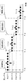
- FIG. 3 is a diagram illustrating an example of detecting a failure in the relay section in the monitoring device 100.
- the transmitter 101 repeatedly transmits an optical pulse to the submarine cable 300.
- the receiver 102 receives the monitoring signal looped back by each of the repeater 201 to the repeater 20 m.
- the control unit 103 measures the reception level of the received monitoring signal, and records the light level for each relay section based on the measurement result of the reception level. As a result, the control unit 103 calculates the time variation of the light level in the relay section n.
- [1] to [3] in FIG. 3 are examples of loss distribution for each relay section at different times after the start of monitoring.
- the horizontal axis of [1] to [3] in FIG. 3 is the relay section, and the vertical axis is the optical level of the monitoring signal of the corresponding relay section.
- [4] to [6] in FIG. 3 are examples of fluctuations in the light level in the relay section n.
- the horizontal axis of [4] to [6] in FIG. 3 is the time, and the vertical axis is the light level of the relay section n.
- [1] in FIG. 3 shows the light level when no failure has occurred after the start of monitoring.
- the initial value of the light level of each relay section at the start of monitoring is normalized as the reference level REF1.
- the fluctuation of the light level after the start of monitoring corresponds to the fluctuation of the loss with respect to the initial value.
- the light levels of each relay section are almost the same.
- [4] in FIG. 3 shows the time variation of the light level in the relay section n in the situation of [1] in FIG.
- the light level in the relay section n is constant over time.
- the control unit 103 of the monitoring device 100 determines that a failure has occurred when the light level is equal to or lower than the level (REF1-TH1) indicated by the first threshold value TH1.
- [2] in FIG. 3 is an example of the light level at the failure occurrence time T1.
- the reception level of the monitoring signal looped back by the repeater n and the repeater farther from the monitoring device 100 at the receiver 102 is lowered. Therefore, the light level of the relay section n is lower than that of REF1. Further, the light levels other than the relay section n are not affected by the loss fluctuation of the relay section n.
- [5] in FIG. 3 shows an example of time fluctuation of the light level of the relay section n before and after the time T1.
- [5] of FIG. 3 shows an example in which the light level in the relay section n fluctuates above the first threshold value TH1 at the time T1 when the failure A occurs, and maintains a substantially constant value after the light level drops.
- [3] and [6] of FIG. 3 are diagrams for explaining the resetting of the reference level and the threshold value after the occurrence of the failure A in the relay section n.
- the control unit 103 sets and records the light level of the relay section n lowered due to the occurrence of the failure A as the second reference level REF2. Further, the control unit 103 sets and records a second threshold value TH2 corresponding to the second reference level REF2.
- the control unit 103 may autonomously perform such resetting of the reference level and the threshold value. Since the light level does not fluctuate in the relay section n + 1 and the relay section farther from the monitoring device 100, the reference level and the threshold value remain REF1 and TH1, respectively.
- the first reference level REF1 may be a normalized optical level immediately after the start of operation of the submarine cable system 1.
- the second reference level REF2 may be the light level of the relay section n immediately after the occurrence of the failure A. Further, the first and second reference levels may be determined from the light level calculated after the transient fluctuation of the light level due to the start of operation or the occurrence of a failure has converged. The time for convergence of such fluctuations is generally about several minutes. For these reference levels, the average value or the median value of the light levels calculated multiple times may be used. Further, the first threshold value TH1 and the second threshold value TH2 may be the same or different. For example, by setting TH1> TH2, the detection sensitivity of the second and subsequent failures in the relay section n can be increased.
- the monitoring device 100 can continue to monitor all relay sections by repeatedly transmitting the monitoring signal. Further, by resetting the reference level according to the occurrence of the failure and recording the content of the failure and the content of the reset, the monitoring device 100 has caused a failure in the relay section n in the past, and the reference level is REF1. It can be known that it has changed to REF2. Then, the monitoring device 100 can detect that a new fault B has occurred when the light level in the relay section n exceeds the range defined by REF2 and TH2 after the fault A has occurred.
- FIG. 4 is a diagram showing an example of time variation of the light level in the relay section n.
- the setting of the second reference level REF2 to the fourth REF4 and the corresponding threshold values TH2 to TH4 when a plurality of failures occur in the relay section n will be described.
- the control unit 103 determines that the failure A has occurred when the light level is equal to or lower than the light level determined by the first reference level REF1 and the first threshold value TH1 at the time T1.
- the control unit 103 sets and records a second reference level REF2 and a second threshold value TH2 according to the light level after the occurrence of the failure A.
- the control unit 103 sets a fourth reference level REF4 and a corresponding fourth threshold value TH4 according to the light level after the failure C occurs. And record. After that, the control unit 103 similarly sets and records the reference level and the threshold value each time a failure occurs. As a result, the monitoring device 100 can record past failures and prepare for detection of failures that occur later.
- FIG. 5 is a diagram for explaining the detection of a failure in the relay section n.
- FIG. 6 is a flowchart showing an example of a failure detection procedure. The detection and recording of failures in the relay section n will be described with reference to FIGS. 4 to 6.
- the first reference level REF1 and the first threshold value TH1 are set (step S01 in FIG. 6).
- the control unit 103 repeats the measurement of the light level L (steps S02 to S03).
- the transmitter 101 may transmit the next monitoring signal to the submarine cable 300 after the return light from all the repeaters for a certain monitoring signal is received by the receiver 102.
- the control unit 103 determines that the failure A has occurred, and the failure A The occurrence is recorded as a determination result (step S04).
- the determination result may include the failure mode and the amount of failure of failure A.
- the failure mode is, for example, a state of failure (decreased light level, etc.), and the amount of failure is, for example, the degree of failure.
- the control unit 103 sets the second reference level REF2 and the second threshold value TH2 (step S05).
- the amount of obstacle may include the amount of decrease in REF1, TH1 and light level at the time of detection of obstacle A.
- the second reference level REF2 and the second threshold value TH2 may be set according to the light level at the time of occurrence of the obstacle A.
- the control unit 103 repeats the measurement of the light level L (steps S06 to S07).
- the control unit 103 determines that the failure B has occurred, and causes the failure B to occur. It is recorded as a determination result (step S08).
- the control unit 103 sets a third reference level REF3 and a third threshold value TH3 (step S09).
- the amount of obstacle B may include the amount of decrease in REF2, TH2 and light level at the time of detection of obstacle B.
- the third reference level REF3 and the third threshold value TH3 may be set according to the light level at the time of occurrence of the obstacle B.
- the control unit 103 repeats the measurement of the light level L (steps S10 to S11).
- the control unit 103 determines that the failure C has occurred, and determines that the failure C has occurred. It is recorded as a determination result (step S12).
- the fourth reference level REF4 and the fourth threshold value TH4 are set (step S13).
- the fourth reference level REF4 and the fourth threshold value TH4 may be set according to the light level at the time of occurrence of the obstacle C. After that, the control unit 103 repeats the measurement of the light level L (step S14). The control unit 103 can continue to detect the failure in the same manner thereafter.
- the monitoring device 100 having the above functions can be called a failure detection device. (Modified example of the first embodiment)
- the first embodiment also exerts its effect by the following modification. (1)
- the control unit 103 may set a failure detection standard different from that of other relay sections in a specific relay section.
- the control unit 103 may determine the occurrence of a failure based on the average value, the median value, or the like of the results of a plurality of measurements of the light level.
- the control unit 103 may determine that a failure has occurred in the relay section n when the light level in the relay section n increases by a predetermined threshold value or more from the initial value.
- the determination of the failure may be performed based on the fluctuation of the light level in the plurality of relay sections. For example, when the control unit 103 detects a failure in any of the continuous relay section n-1, the relay section n, and the relay section n + 1, and the decrease in the light level of the relay section n is the largest among these relay sections. , It may be determined that a failure has occurred in the relay section n. Alternatively, in such a case, the control unit 103 determines that a failure has occurred in all of these relay sections, determines that the failure in the relay section n is the most important, and determines that determination as a determination result. It may be included in and recorded.
- the control unit 103 may reset the reference level and the threshold value only for the relay section in which the failure is detected. Alternatively, the control unit 103 may reset the reference level and the threshold value of the relay section other than the relay section in which the failure is detected, triggered by the detection of the failure. (6) The control unit 103 may record the patterns of the positional fluctuation and the temporal fluctuation of the light level illustrated in [1] to [6] of FIG. 3 in association with the obstacles, respectively. Then, when a pattern similar to the recorded pattern occurs in the submarine cable system in operation, the control unit 103 may presume that a failure similar to a past failure having that pattern has occurred. ..
- the submarine cable system 1 and the monitoring device 100 of the first embodiment can detect when a plurality of failures occur in the section in which the optical signal is transmitted. The reason is that after the failure occurs, a new reception level and threshold value are set as a reference for detecting the failure that occurs thereafter.
- FIG. 7 is a diagram showing a configuration example of the monitoring device 500 according to the second embodiment of the present invention.
- the function and configuration of the monitoring device 500 are the same as those of the monitoring device 100 of the first embodiment. That is, the monitoring device 500 includes a transmitter 101, a receiver 102, and a control unit 103.
- the transmitter 101 is responsible for transmitting means for transmitting the monitoring signal.
- the receiver 102 serves as a receiving means for receiving an optical signal.
- the control unit 103 serves as a control means for controlling and setting the inside of the monitoring device 500.
- the optical signal transmitted by the transmitter 101 can be called a first optical signal. Further, the optical signal received by the receiver 102 can be called a second optical signal.
- FIG. 8 is a flowchart showing an operation example of the monitoring device 500.
- the transmitter 101 transmits the first optical signal to the optical transmission line (step S51 in FIG. 8).
- the receiver 102 receives the second optical signal from the optical transmission line in response to the transmission of the first optical signal.
- the control unit 103 measures the reception level of the received second optical signal (step S52). Further, the control unit 103 specifies a section in which the second optical signal corresponding to the first optical signal is generated (step S53).
- the control unit 103 may specify the section in which the second optical signal is generated based on the transmission time of the first optical signal and the reception time of the second optical signal.
- the control unit 103 calculates the optical level L corresponding to the loss of the specified section based on the reception level (step S54), and determines the measured reception level and the specified section of the second optical signal. Record in association with the first time, which is the reception time.
- control unit 103 determines that the failure A has occurred in the section (step S55: YES). Step S56), record failure A. After recording the fault A, the control unit 103 sets a second reference level and a second threshold (step S57).
- the procedure of steps S58 to S60 is the same as that of steps S52 to S54.
- the control unit 103 measures the reception level of the second optical signal (step S58) and identifies the section in which the second optical signal is generated (step S59).
- the control unit 103 calculates the optical level L corresponding to the loss of the specified section based on the reception level (step S60), and determines the measured reception level and the specified section of the second optical signal. Record in association with the first time, which is the reception time.
- step S61 When the light level fluctuates from the second reference level to the second threshold value or more (step S61: YES), the control unit 103 determines that the failure B has occurred in the section. After that, the reference level and the threshold value may be reset and the failure may be detected in the same manner as in step S57.
- the monitoring device 500 having such a function can be called a failure detection device.
- the monitoring device 500 can detect each of them as different failures (fault A and failure B). The reason is that after the occurrence of the failure A, the reception level and the threshold value as a reference for detecting the failure B that occurs thereafter are newly set.
- the section in which the second optical signal is generated according to the first optical signal is specified, and the section is identified.
- the light level corresponding to the loss in the section is calculated based on the reception level, and when the light level in the section fluctuates from the first reference level to the first threshold value or more, the first failure occurs in the section.
- a second reference level and a second threshold value are set, and when the light level fluctuates from the second reference level to the second threshold value or more.
- a control means for determining that a second failure has occurred in the section, and A fault detection device comprising.
- Appendix 2 The transmitting means repeatedly transmits an optical pulse as the first optical signal, The receiving means measures the receiving level in correspondence with each of the optical pulses.
- the optical transmission line is a submarine cable in which a plurality of optical repeaters are connected in series.
- the second optical signal is the first optical signal looped back in each of the plurality of optical repeaters.
- the control means specifies the section based on the transmission time of the first optical signal, the reception time of the second optical signal, and the distances to each of the plurality of repeaters, according to Appendix 1 or 2. Failure detector.
- Appendix 4 The fault detection device according to Appendix 3, wherein the section includes one of the plurality of optical repeaters that generate the second optical signal as a loopback signal of the first optical signal.
- Appendix 5 The control means is described in any one of Appendix 1 to 4, which sets the second reference level and the second threshold value according to the light level when the first failure occurs. Fault detector.
- the control means determines at least one of the occurrence of the first failure and the occurrence of the second failure based on the fluctuation of the light level in the plurality of sections, any one of Supplementary notes 1 to 5.
- the control means sets a reference level and a threshold value for a section other than the section in which the failure is detected, triggered by the occurrence of at least one of the first failure and the second failure.
- the fault detection device according to item 1.
- Appendix 9 Optical transmission line and The fault detection device according to any one of Appendix 1 to 8 is provided.
- the fault detection device transmits the first optical signal to the optical transmission line and receives the second optical signal from the optical transmission line.
- the first optical signal is transmitted to the optical transmission line, In response to the transmission of the first optical signal, the second optical signal is received from the optical transmission line, and the second optical signal is received.
- the reception level of the second optical signal is measured and
- the section in which the second optical signal is generated according to the first optical signal is specified, and the section is identified.
- the light level corresponding to the loss in the section is calculated based on the reception level.
- a second reference level and a second threshold are set. When the light level fluctuates from the second reference level by the second threshold value or more, it is determined that a second obstacle has occurred in the section. Failure detection method.
- the optical transmission line is a submarine cable in which a plurality of optical repeaters are connected in series.
- the second optical signal is the first optical signal looped back in each of the plurality of optical repeaters.
- the section is specified based on the transmission time of the first optical signal, the reception time of the second optical signal, and the distances to each of the plurality of repeaters.
- the failure detection method according to Appendix 10 or 11.
- Appendix 13 The fault detection method according to Appendix 12, wherein the section includes one of the plurality of optical repeaters that generate the second optical signal as a loopback signal of the first optical signal.
- Appendix 14 The failure detection method according to any one of Appendix 10 to 13, wherein the second reference level and the second threshold value are set according to the light level when the first failure occurs.
- Appendix 15 The obstacle according to any one of Appendix 10 to 14, wherein at least one of the occurrence of the first obstacle and the occurrence of the second obstacle is determined based on the fluctuation of the light level in the plurality of said sections. Detection method.
- Appendix 16 The item according to any one of Appendix 10 to 15, which sets a reference level and a threshold value for a section other than the section in which the failure is detected, triggered by the occurrence of at least one of the first failure and the second failure. Failure detection method.
- Appendix 17 The fault detection method according to any one of Appendix 10 to 16, wherein the fluctuation of the light level is recorded in association with the fault, and the occurrence of the fault is determined based on the recorded fluctuation of the light level.
- the functions and procedures described in each of the above embodiments may be realized by executing a program by a central processing unit (CPU) included in each positioning device.
- the program is recorded on a fixed, non-transitory recording medium.
- a semiconductor memory or a fixed magnetic disk device is used as the recording medium, but the recording medium is not limited thereto.
- the CPU is, for example, a computer provided in the control unit 103, but the CPU may be provided in another place in the monitoring device 100.
- Submarine cable system 200 201-20m Repeater 100 Monitoring device 101 Transmitter 102 Receiver 103 Control unit 111, 112 Transmission line interface 121, 122 Optical transmission device 211, 212 Optical amplifier 220 Loopback circuit 221, 222 Optical coupler 223 Optical filter 300 Submarine cable 500 Monitoring device
Abstract
In order to provide a technology for detecting a plurality of faults that occurred in sections through which optical signals are transferred, this fault detection apparatus is provided with: a transmitter that transmits a first optical signal through an optical transmission line; a receiver that receives, in response to the transmission of the first optical signal, a second optical signal from the optical transmission line, and measures the reception level of the second optical signal; and a control unit that specifies a section where the second optical signal corresponding to the first optical signal was generated, calculates an optical level corresponding to a loss in said section on the basis of the reception level, determines that a first fault has occurred in the section when the optical level in the section has changed from a first reference level by a first threshold or more, sets a second reference level and a second threshold after occurrence of the first fault, and determines that a second fault has occurred in the section when the optical level has changed from the second reference level by the second threshold or more.
Description
本発明は障害検出装置、障害検出方法及び海底ケーブルシステムに関し、特に、光信号が伝送される区間における障害を検出可能な障害検出装置、障害検出方法及び海底ケーブルシステムに関する。
The present invention relates to a fault detection device, a fault detection method and a submarine cable system, and more particularly to a fault detection device, a fault detection method and a submarine cable system capable of detecting a fault in a section in which an optical signal is transmitted.
海底ケーブルシステムは、陸上に設置された端局の間を海底に敷設された光ケーブルで接続する、光通信システムである。海底ケーブルシステムを監視する手法の1つとして、端局から送信された監視光の戻り光の受信レベルを監視する方法が知られている。戻り光の受信レベルが低下した場合や受信レベルの時間的な変動が大きい場合には、監視光が伝搬した光ケーブルに障害があると推定できる。
The submarine cable system is an optical communication system that connects end stations installed on land with an optical cable laid on the seabed. As one of the methods for monitoring the submarine cable system, a method for monitoring the reception level of the return light of the monitoring light transmitted from the terminal station is known. If the reception level of the return light drops or the reception level fluctuates greatly over time, it can be estimated that there is a problem with the optical cable through which the monitoring light propagated.
海底ケーブルシステムで用いられる中継器には、監視光を折り返す機能を持つものがある。端局の送信器は、監視光を海底ケーブルへ送出する。端局に接続された各中継器は監視光をループバックし、ループバックされた監視光(戻り光)を端局へ返送する。端局の受信器は、戻り光を受信する。端局は、光パルスを繰り返し送信することで、それぞれの中継器からの戻り光の受信レベルの時間的な変動を知ることができる。本発明に関連して、特許文献1には光信号のレベル変動に基づいて障害を検知するための技術が記載されている。
Some repeaters used in submarine cable systems have the function of returning the monitoring light. The transmitter of the terminal station sends the monitoring light to the submarine cable. Each repeater connected to the terminal station loops back the monitoring light and returns the looped-back monitoring light (return light) to the terminal station. The terminal receiver receives the return light. By repeatedly transmitting the optical pulse, the terminal station can know the temporal fluctuation of the reception level of the return light from each repeater. In connection with the present invention, Patent Document 1 describes a technique for detecting an obstacle based on a level fluctuation of an optical signal.
一般的な海底ケーブルシステムでは、中継器において光ファイバ伝送路を折り返した際の、システムの敷設時の戻り光の受信レベルを初期値としていた。そして、戻り光の受信レベルが初期値から所定の閾値以上低下すると障害発生と判定していた。この場合、第1の障害が発生し戻り光の受信レベルが閾値以上低下した後に同じ区間で第2の障害によりさらに戻り光の受信レベルが低下しても、すでに第1の障害で警報が発出されているため、第2の障害を別の障害として検出できないという課題がある。
(発明の目的)
本発明は、光信号が伝送される区間において複数の障害が発生した場合に、それぞれを検出するための技術を提供することを目的とする。 In a general submarine cable system, the initial value is the reception level of the return light when the system is laid when the optical fiber transmission line is folded back in the repeater. Then, when the reception level of the return light drops by a predetermined threshold value or more from the initial value, it is determined that a failure has occurred. In this case, even if the first failure occurs and the return light reception level drops by the threshold value or more and then the return light reception level further drops due to the second failure in the same section, an alarm is already issued by the first failure. Therefore, there is a problem that the second failure cannot be detected as another failure.
(Purpose of Invention)
An object of the present invention is to provide a technique for detecting when a plurality of failures occur in a section in which an optical signal is transmitted.
本発明の障害検出装置は、
第1の光信号を光伝送路に送信する送信手段と、
前記第1の光信号の送信に応じて前記光伝送路から第2の光信号を受信し、前記第2の光信号の受信レベルを測定する受信手段と、
前記第1の光信号に応じた前記第2の光信号が生成された区間を特定し、
前記区間の損失に対応する光レベルを前記受信レベルに基づいて算出し、前記区間の光レベルが第1の基準レベルから第1の閾値以上変動した場合に、前記区間において第1の障害が発生したと判定し、前記第1の障害の発生後、第2の基準レベル及び第2の閾値を設定し、前記光レベルが前記第2の基準レベルから前記第2の閾値以上変動した場合に、前記区間において第2の障害が発生したと判定する制御手段と、
を備える。 The fault detection device of the present invention
A transmission means for transmitting the first optical signal to the optical transmission line,
A receiving means that receives a second optical signal from the optical transmission line in response to the transmission of the first optical signal and measures the reception level of the second optical signal.
The section in which the second optical signal is generated according to the first optical signal is specified, and the section is identified.
The light level corresponding to the loss in the section is calculated based on the reception level, and when the light level in the section fluctuates from the first reference level to the first threshold value or more, the first failure occurs in the section. After the occurrence of the first obstacle, a second reference level and a second threshold value are set, and when the light level fluctuates from the second reference level to the second threshold value or more. A control means for determining that a second failure has occurred in the section, and
To be equipped.
本発明の障害検出方法は、
第1の光信号を光伝送路に送信し、
前記第1の光信号の送信に応じて前記光伝送路から第2の光信号を受信し、
前記第2の光信号の受信レベルを測定し、
前記第1の光信号に応じた前記第2の光信号が生成された区間を特定し、
前記区間の損失に対応する光レベルを前記受信レベルに基づいて算出し、
前記区間の光レベルが第1の基準レベルから第1の閾値以上変動した場合に、前記区間において第1の障害が発生したと判定し、
前記第1の障害の発生後、第2の基準レベル及び第2の閾値を設定し、
前記光レベルが前記第2の基準レベルから前記第2の閾値以上変動した場合に、前記区間において第2の障害が発生したと判定する、
手順を含む。 The fault detection method of the present invention
The first optical signal is transmitted to the optical transmission line,
In response to the transmission of the first optical signal, the second optical signal is received from the optical transmission line, and the second optical signal is received.
The reception level of the second optical signal is measured and
The section in which the second optical signal is generated according to the first optical signal is specified, and the section is identified.
The light level corresponding to the loss in the section is calculated based on the reception level.
When the light level in the section fluctuates from the first reference level by the first threshold value or more, it is determined that the first obstacle has occurred in the section.
After the occurrence of the first failure, a second reference level and a second threshold are set.
When the light level fluctuates from the second reference level by the second threshold value or more, it is determined that a second obstacle has occurred in the section.
Including the procedure.
本発明は、光信号が伝送される区間において複数の障害が発生した場合に、それぞれを検出することを可能とする。
The present invention makes it possible to detect when a plurality of failures occur in a section in which an optical signal is transmitted.
(第1の実施形態)
図1は、本発明の第1の実施形態の海底ケーブルシステム1の構成例を示すブロック図である。海底ケーブルシステム1は、監視装置100、伝送路インタフェース111及び112、m台の中継器201-20mを備える。文字mは自然数である。中継器201-20mの構成は同一である。以下では、中継器201-20mを総称する場合は中継器200と記載する。中継器200は海底に設置される。伝送路インタフェース111、112及び中継器200は、海底ケーブル300によって縦続接続されている。海底ケーブル300は光ファイバ及び給電線を含むケーブルである。中継器200は、図示されない陸上の電源装置から海底ケーブル300を介した給電を受けて動作する。 (First Embodiment)
FIG. 1 is a block diagram showing a configuration example of thesubmarine cable system 1 according to the first embodiment of the present invention. The submarine cable system 1 includes a monitoring device 100, transmission line interfaces 111 and 112, and m repeaters 201-20 m. The letter m is a natural number. The configuration of the repeater 201-20m is the same. In the following, when the repeater 201-20m is generically referred to, it will be referred to as the repeater 200. The repeater 200 is installed on the seabed. The transmission line interfaces 111 and 112 and the repeater 200 are vertically connected by a submarine cable 300. The submarine cable 300 is a cable including an optical fiber and a feeding line. The repeater 200 operates by receiving power supplied from a power supply device on land (not shown) via a submarine cable 300.
図1は、本発明の第1の実施形態の海底ケーブルシステム1の構成例を示すブロック図である。海底ケーブルシステム1は、監視装置100、伝送路インタフェース111及び112、m台の中継器201-20mを備える。文字mは自然数である。中継器201-20mの構成は同一である。以下では、中継器201-20mを総称する場合は中継器200と記載する。中継器200は海底に設置される。伝送路インタフェース111、112及び中継器200は、海底ケーブル300によって縦続接続されている。海底ケーブル300は光ファイバ及び給電線を含むケーブルである。中継器200は、図示されない陸上の電源装置から海底ケーブル300を介した給電を受けて動作する。 (First Embodiment)
FIG. 1 is a block diagram showing a configuration example of the
監視装置100は、送信器101と、受信器102と、制御部103とを備える。送信器101は監視信号を送信する。受信器102は、中継器200でループバックされた監視信号を受信し、監視信号の受信レベルに応じた電気信号を制御部103へ出力する。制御部103は監視装置100を制御する。監視信号は、海底ケーブルシステム1を監視するための光信号である。
The monitoring device 100 includes a transmitter 101, a receiver 102, and a control unit 103. The transmitter 101 transmits a monitoring signal. The receiver 102 receives the monitoring signal looped back by the repeater 200, and outputs an electric signal corresponding to the reception level of the monitoring signal to the control unit 103. The control unit 103 controls the monitoring device 100. The monitoring signal is an optical signal for monitoring the submarine cable system 1.
伝送路インタフェース111及び112は、監視装置100等の陸上に設置された機器と海底ケーブル300とを接続するインタフェースである。伝送路インタフェース111は、送信器101が送信する監視信号と、ユーザデータを含む光信号(主信号)とを合波して海底ケーブル300へ送出する。伝送路インタフェース111は、さらに、海底ケーブル300から受信した光信号を、監視信号と主信号とに分離する。それぞれの中継器200においてループバックされた監視信号は、伝送路インタフェース111において主信号と分離され、受信器102で受信される。また、中継器20mに接続された海底ケーブル300と陸上の機器とを接続するために、伝送路インタフェース111と同様の機能を備える伝送路インタフェース112が設置されてもよい。
The transmission line interfaces 111 and 112 are interfaces for connecting a device installed on land such as a monitoring device 100 and a submarine cable 300. The transmission line interface 111 combines the monitoring signal transmitted by the transmitter 101 and the optical signal (main signal) including the user data and sends the signal to the submarine cable 300. The transmission line interface 111 further separates the optical signal received from the submarine cable 300 into a monitoring signal and a main signal. The monitoring signal looped back in each repeater 200 is separated from the main signal in the transmission line interface 111 and received by the receiver 102. Further, in order to connect the submarine cable 300 connected to the repeater 20 m and the equipment on land, a transmission line interface 112 having the same function as the transmission line interface 111 may be installed.
主信号は、例えば、光伝送装置121と光伝送装置122との間で伝送される波長多重信号である。光伝送装置121及び122は、それぞれ、伝送路インタフェース111及び112に接続された光送受信装置である。伝送路インタフェース111は監視装置100に含まれてもよい。あるいは、伝送路インタフェース111及び112は、それぞれ、光伝送装置121及び122に含まれてもよい。伝送路インタフェース111及び112は、監視信号と主信号との波長多重及び波長分離を行う合波分波機能を備える。
The main signal is, for example, a wavelength division multiplexing signal transmitted between the optical transmission device 121 and the optical transmission device 122. The optical transmission devices 121 and 122 are optical transmission / reception devices connected to the transmission line interfaces 111 and 112, respectively. The transmission line interface 111 may be included in the monitoring device 100. Alternatively, the transmission line interfaces 111 and 112 may be included in the optical transmission devices 121 and 122, respectively. The transmission line interfaces 111 and 112 have a combine demultiplexing function for performing wavelength division multiplexing and wavelength separation between a monitoring signal and a main signal.
監視信号は規定されたピークレベル及び持続時間を持つ光パルスである。監視信号の波長は、主信号の波長と重複しない波長に設定される。監視信号の波長は中継器200が中継可能な波長帯域内にあることが好ましい。主信号の帯域外の波長を監視信号の波長としてもよい。あるいは、使用されていない主信号の波長が監視信号の波長に使用されてもよい。
The monitoring signal is an optical pulse with a specified peak level and duration. The wavelength of the monitoring signal is set to a wavelength that does not overlap with the wavelength of the main signal. The wavelength of the monitoring signal is preferably within the wavelength band that the repeater 200 can relay. A wavelength outside the band of the main signal may be used as the wavelength of the monitoring signal. Alternatively, the wavelength of the unused main signal may be used as the wavelength of the monitoring signal.
送信器101は、例えば光源及び光源のパルス変調器を含む。送信器101は、伝送路インタフェース111を介して海底ケーブル300へ監視信号を繰り返し出力する。受信器102は光電変換器であり、例えばフォトダイオードを含む。受信器102は各中継器からループバックされた監視信号(戻り光)を受信し、監視信号の受信レベルに応じた電気信号を制御部103へ出力する。制御部103は、当該電気信号に基づいて監視信号の受信レベルを測定し、監視信号をループバックさせた中継器及び測定時刻と受信レベルとを関連付けて、不揮発性半導体メモリ等の記憶部に記録する。記憶部は、例えば制御部103に備えられる。
The transmitter 101 includes, for example, a light source and a pulse modulator of the light source. The transmitter 101 repeatedly outputs a monitoring signal to the submarine cable 300 via the transmission line interface 111. The receiver 102 is a photoelectric converter and includes, for example, a photodiode. The receiver 102 receives the loopbacked monitoring signal (return light) from each repeater, and outputs an electric signal corresponding to the reception level of the monitoring signal to the control unit 103. The control unit 103 measures the reception level of the monitoring signal based on the electric signal, associates the repeater in which the monitoring signal is looped back, and the measurement time with the reception level, and records it in a storage unit such as a non-volatile semiconductor memory. do. The storage unit is provided in, for example, the control unit 103.
図2は、監視信号のループバックを説明する図である。図2には、同一の構成を持つ3台の中継器20n-2、20n-1、20nが例示される。文字nは3以上m以下の整数である。中継器20n-1と中継器20nとの間の海底ケーブル300及び中継器20nを含む区間を、以下では中継区間nと記載する。また、中継器202と中継器201との間の海底ケーブル300を含む区間は中継区間2と呼ぶことができる。中継器201と伝送路インタフェース111との間の海底ケーブル300を含む区間は中継区間1と呼ぶことができる。中継器200は、入力された光信号を増幅する光増幅器211、212及びループバック回路220を備える。
FIG. 2 is a diagram for explaining the loopback of the monitoring signal. FIG. 2 illustrates three repeaters 20n-2, 20n-1, and 20n having the same configuration. The character n is an integer of 3 or more and m or less. The section including the submarine cable 300 and the repeater 20n between the repeater 20n-1 and the repeater 20n will be referred to as a relay section n below. Further, the section including the submarine cable 300 between the repeater 202 and the repeater 201 can be referred to as a relay section 2. The section including the submarine cable 300 between the repeater 201 and the transmission line interface 111 can be referred to as a relay section 1. The repeater 200 includes optical amplifiers 211 and 212 for amplifying the input optical signal and a loopback circuit 220.
ループバック回路220は、監視装置100が下り方向(図2の左から右方向)へ送信した監視信号を上り方向(図2の右から左方向)に折り返す。ループバック回路220は、例えば、海底ケーブル300に含まれる1組のファイバペア(fiber pair, FP)の間を2台の1×2光カプラ221、222を用いて接続するように構成される。光カプラ221と光カプラ222との間には、光フィルタ223が配される。光フィルタ223は、監視信号の波長の光を透過し、主信号の波長の光を阻止する。光フィルタ223には、光ファイバグレーティング又は誘電体多層膜フィルタが用いられてもよい。このような構成により、下り方向の海底ケーブルを伝搬する監視信号は、各中継器のループバック回路220でループバックされる。ループバックされた監視信号は、上り方向の海底ケーブルを伝搬して監視装置100へ戻る。なお、監視信号を中継器200がループバックさせる図2の構成は例であり、ループバック回路220の構成を限定しない。
The loopback circuit 220 returns the monitoring signal transmitted by the monitoring device 100 in the downward direction (from left to right in FIG. 2) in the upward direction (from right to left in FIG. 2). The loopback circuit 220 is configured to connect, for example, between a pair of fibers (fiber pair, FP) included in the submarine cable 300 by using two 1 × 2 optical couplers 221 and 222. An optical filter 223 is arranged between the optical coupler 221 and the optical coupler 222. The optical filter 223 transmits the light having the wavelength of the monitoring signal and blocks the light having the wavelength of the main signal. An optical fiber grating or a dielectric multilayer filter may be used as the optical filter 223. With such a configuration, the monitoring signal propagating the submarine cable in the downward direction is looped back by the loopback circuit 220 of each repeater. The loopbacked monitoring signal propagates through the submarine cable in the upward direction and returns to the monitoring device 100. The configuration of FIG. 2 in which the repeater 200 loops back the monitoring signal is an example, and the configuration of the loopback circuit 220 is not limited.
監視装置100は、監視信号を繰り返し海底ケーブル300に送出する。図2は、海底ケーブル300に入力された1個の監視信号Pの伝搬の例を示す。光増幅器211は、監視信号と主信号とが波長多重された光信号を増幅する。光増幅器211は、下り方向へ伝送される主信号及び監視信号の、各中継区間のレベルの低下を補償する。各中継器のループバック回路220は、下り方向に伝搬する監視信号Pをループバックし、上り方向へ送出する。監視信号Pがループバックされる時刻は監視装置100に近い中継器ほど早い。このため、ループバックされた監視信号は、監視信号P(n-2)、P(n-1)、P(n)の順に、受信器102で受信される。受信器102は、受信した監視信号の受信レベルを測定する。ここで、監視信号の送信時刻と受信時刻との差及び監視信号の伝搬速度から、受信した監視信号の伝搬距離が計算できる。監視装置100からループバックされた中継器200までの距離は伝搬距離の半分と考えてよい。従って、制御部103は受信した監視信号がループバックされた中継器を特定できる。
The monitoring device 100 repeatedly sends a monitoring signal to the submarine cable 300. FIG. 2 shows an example of propagation of one monitoring signal P input to the submarine cable 300. The optical amplifier 211 amplifies an optical signal in which the monitoring signal and the main signal are wavelength-multiplexed. The optical amplifier 211 compensates for a decrease in the level of each relay section of the main signal and the monitoring signal transmitted in the downlink direction. The loopback circuit 220 of each repeater loops back the monitoring signal P propagating in the downward direction and sends it out in the upward direction. The time at which the monitoring signal P is looped back is earlier as the repeater is closer to the monitoring device 100. Therefore, the loopbacked monitoring signal is received by the receiver 102 in the order of the monitoring signals P (n-2), P (n-1), and P (n). The receiver 102 measures the reception level of the received monitoring signal. Here, the propagation distance of the received monitoring signal can be calculated from the difference between the transmission time and the reception time of the monitoring signal and the propagation speed of the monitoring signal. The distance from the monitoring device 100 to the loopback repeater 200 may be considered to be half the propagation distance. Therefore, the control unit 103 can identify the repeater to which the received monitoring signal is looped back.
制御部103は、監視信号の受信レベルを、監視信号がループバックされた中継器及び測定時刻と関連付けて記録する。なお、送信される監視信号の光パルスの幅及び送信間隔は、隣接する中継器においてループバックされたそれぞれの監視信号が受信器102において重複して受信されないように設定されることが好ましい。
The control unit 103 records the reception level of the monitoring signal in association with the repeater in which the monitoring signal is looped back and the measurement time. It is preferable that the width of the optical pulse and the transmission interval of the transmitted monitoring signal are set so that the respective monitoring signals looped back in the adjacent repeaters are not received in duplicate in the receiver 102.
隣接した2台の中継器でループバックされたそれぞれの監視信号の受信レベルの変動から、これらの中継器の間の中継区間の損失の変動を知ることができる。例えば、中継器20n-1でループバックされた監視信号P(n-1)の中継器20n-2の入力における光パワーをS(n-1)、中継器20nでループバックされた監視信号P(n)の中継器20n-1における光パワーをS(n)とする。各中継器の入出力では伝送される光信号のスペクトルのプロファイルは保存される。このため、受信器102における監視信号P(n-1)の受信レベルと監視信号P(n)の受信レベルとの差の変動は、中継区間nの両端の光パワーの差(レベル差)S(n-1)-S(n)の変動と対応する。従って、まず、監視装置100は、監視信号Pを繰り返し海底ケーブル300へ出力する。そして、制御部103は、隣接する監視信号P(n-1)とP(n)の受信レベルの差の時間的な変動を求めて記録する。このようにして、中継区間nにおける損失の変動を監視できる。
From the fluctuation of the reception level of each monitoring signal looped back by two adjacent repeaters, it is possible to know the fluctuation of the loss in the relay section between these repeaters. For example, the optical power at the input of the repeater 20n-2 of the monitoring signal P (n-1) looped back by the repeater 20n-1 is S (n-1), and the monitoring signal P looped back by the repeater 20n. Let S (n) be the optical power of the repeater 20n-1 of (n). The spectral profile of the transmitted optical signal is stored at the input and output of each repeater. Therefore, the variation in the difference between the reception level of the monitoring signal P (n-1) and the reception level of the monitoring signal P (n) in the receiver 102 is the difference in optical power (level difference) S at both ends of the relay section n. Corresponds to the variation of (n-1) -S (n). Therefore, first, the monitoring device 100 repeatedly outputs the monitoring signal P to the submarine cable 300. Then, the control unit 103 obtains and records the temporal variation of the difference between the reception levels of the adjacent monitoring signals P (n-1) and P (n). In this way, the fluctuation of the loss in the relay section n can be monitored.
なお、上り方向の各中継器の出力において、海底ケーブルシステム1に障害が発生していない場合には当該中継器でループバックされた監視信号のレベルが同一となるように海底ケーブルシステム1が設計されてもよい。このような場合には、レベル差S(n-1)-S(n)は中継区間nの損失を示す。また、このような場合には受信器102における監視信号P(n-1)の受信レベルと監視信号P(n)の受信レベルとの差は、中継区間nの損失を示す。
The submarine cable system 1 is designed so that the level of the monitoring signal looped back by the repeater is the same when the submarine cable system 1 does not have a failure in the output of each repeater in the upstream direction. May be done. In such a case, the level difference S (n-1) -S (n) indicates the loss of the relay section n. Further, in such a case, the difference between the reception level of the monitoring signal P (n-1) and the reception level of the monitoring signal P (n) in the receiver 102 indicates the loss of the relay section n.
上述のように、中継区間nの損失変動は、監視信号P(n-1)と監視信号P(n)との受信レベルの差の変動と対応させることができる。このため、監視信号P(n-1)の受信レベルと監視信号P(n)の受信レベルとの差に初期値を設定し、ループバックされた監視信号の受信レベルのその後の変動を、それぞれの中継区間の損失変動と対応させて記録することができる。以下では、監視装置100において、中継区間nの損失に対応する受信レベルの差を「中継区間nの光レベル」と記載する。中継区間nのみの損失が増加するとレベル差S(n-1)-S(n)のみが低下するため、中継区間nの光レベルは低下する。すなわち、中継区間nの光レベルの低下は、中継区間nにおける初期値に対する損失増加と対応する。
As described above, the loss fluctuation of the relay section n can correspond to the fluctuation of the difference in reception level between the monitoring signal P (n-1) and the monitoring signal P (n). Therefore, an initial value is set for the difference between the reception level of the monitoring signal P (n-1) and the reception level of the monitoring signal P (n), and the subsequent fluctuations in the reception level of the loopbacked monitoring signal are set respectively. It can be recorded in correspondence with the loss fluctuation of the relay section of. In the following, in the monitoring device 100, the difference in reception level corresponding to the loss in the relay section n will be referred to as “light level in the relay section n”. When the loss of only the relay section n increases, only the level difference S (n-1) −S (n) decreases, so that the light level of the relay section n decreases. That is, the decrease in the light level in the relay section n corresponds to the increase in loss with respect to the initial value in the relay section n.
制御部103は、中継区間nの光レベルが初期値から所定の閾値以上低下した場合に、中継区間nにおいて障害が発生したと判定する。障害が検出されると(すなわち、障害の発生が判定されると)、制御部103は中継区間nにおける以降の障害検出の基準となる新たな基準レベル及び新たな閾値を設定して記録する。この手順について以降に説明する。
The control unit 103 determines that a failure has occurred in the relay section n when the light level in the relay section n drops by a predetermined threshold value or more from the initial value. When a failure is detected (that is, when the occurrence of a failure is determined), the control unit 103 sets and records a new reference level and a new threshold value that serve as a reference for subsequent failure detection in the relay section n. This procedure will be described below.
図3は、監視装置100における中継区間の障害の検出の例を説明する図である。送信器101は、海底ケーブル300に光パルスを繰り返し送信する。受信器102は、中継器201から中継器20mまでのそれぞれでループバックされた監視信号を受信する。制御部103は、受信された監視信号の受信レベルを測定し、受信レベルの測定結果に基づいて中継区間毎の光レベルを記録する。これにより、制御部103は、中継区間nの光レベルの時間変動を算出する。
FIG. 3 is a diagram illustrating an example of detecting a failure in the relay section in the monitoring device 100. The transmitter 101 repeatedly transmits an optical pulse to the submarine cable 300. The receiver 102 receives the monitoring signal looped back by each of the repeater 201 to the repeater 20 m. The control unit 103 measures the reception level of the received monitoring signal, and records the light level for each relay section based on the measurement result of the reception level. As a result, the control unit 103 calculates the time variation of the light level in the relay section n.
図3の[1]から[3]は、それぞれ、監視開始後の異なる時刻における中継区間ごとの損失の分布の例である。図3の[1]から[3]の横軸は中継区間であり、縦軸は対応する中継区間の監視信号の光レベルである。また、図3の[4]から[6]は、中継区間nの光レベルの変動の例である。図3の[4]から[6]の横軸は時刻であり、縦軸は中継区間nの光レベルである。送信器101が光パルスを一定時間ごとに送信することで、制御部103は、定期的かつ自律的に光レベルの変動を監視できる。
[1] to [3] in FIG. 3 are examples of loss distribution for each relay section at different times after the start of monitoring. The horizontal axis of [1] to [3] in FIG. 3 is the relay section, and the vertical axis is the optical level of the monitoring signal of the corresponding relay section. Further, [4] to [6] in FIG. 3 are examples of fluctuations in the light level in the relay section n. The horizontal axis of [4] to [6] in FIG. 3 is the time, and the vertical axis is the light level of the relay section n. When the transmitter 101 transmits an optical pulse at regular intervals, the control unit 103 can periodically and autonomously monitor fluctuations in the optical level.
図3の[1]は監視開始後、障害が未発生の場合の光レベルを示す。図3の[1]では、監視開始時のそれぞれの中継区間の光レベルの初期値は基準レベルREF1として正規化されている。監視開始後の光レベルの変動は、初期値に対する損失変動と対応する。図3の[1]では障害が発生している中継区間が存在しないため、各中継区間の光レベルはほぼ等しい。
[1] in FIG. 3 shows the light level when no failure has occurred after the start of monitoring. In [1] of FIG. 3, the initial value of the light level of each relay section at the start of monitoring is normalized as the reference level REF1. The fluctuation of the light level after the start of monitoring corresponds to the fluctuation of the loss with respect to the initial value. In [1] of FIG. 3, since there is no relay section in which a failure has occurred, the light levels of each relay section are almost the same.
図3の[4]は、図3の[1]の状況で中継区間nの光レベルの時間変動を示す。中継区間nで障害が発生していない場合には、中継区間nの光レベルは時間が経過しても一定である。監視装置100の制御部103は、光レベルが第1の閾値TH1で示されるレベル(REF1-TH1)以下となると障害が発生したと判定する。
[4] in FIG. 3 shows the time variation of the light level in the relay section n in the situation of [1] in FIG. When no failure occurs in the relay section n, the light level in the relay section n is constant over time. The control unit 103 of the monitoring device 100 determines that a failure has occurred when the light level is equal to or lower than the level (REF1-TH1) indicated by the first threshold value TH1.
図3の[2]は、障害の発生時刻T1における光レベルの例である。中継区間nにおいて障害Aが発生した場合には、中継器n-1及びこれよりも監視装置100に近い中継器でループバックされた監視信号の、受信器102における受信レベルは変動しない。一方、中継器n及びこれよりも監視装置100から遠い中継器でループバックされた監視信号の、受信器102における受信レベルは低下する。従って、中継区間nの光レベルはREF1よりも低下する。また、中継区間n以外の光レベルは中継区間nの損失変動の影響を受けない。
[2] in FIG. 3 is an example of the light level at the failure occurrence time T1. When a failure A occurs in the relay section n, the reception level of the monitoring signal looped back by the repeater n-1 and the repeater closer to the monitoring device 100 does not change in the receiver 102. On the other hand, the reception level of the monitoring signal looped back by the repeater n and the repeater farther from the monitoring device 100 at the receiver 102 is lowered. Therefore, the light level of the relay section n is lower than that of REF1. Further, the light levels other than the relay section n are not affected by the loss fluctuation of the relay section n.
図3の[5]は、時刻T1の前後における中継区間nの光レベルの時間変動の例を示す。図3の[5]は、中継区間nの光レベルが障害Aの発生時刻T1で第1の閾値TH1以上に変動し、光レベルの低下後はほぼ一定の値を維持する例を示す。
[5] in FIG. 3 shows an example of time fluctuation of the light level of the relay section n before and after the time T1. [5] of FIG. 3 shows an example in which the light level in the relay section n fluctuates above the first threshold value TH1 at the time T1 when the failure A occurs, and maintains a substantially constant value after the light level drops.
図3の[3]及び[6]は、中継区間nにおける障害Aの発生後の基準レベル及び閾値の再設定を説明する図である。制御部103は、障害Aの発生により低下した中継区間nの光レベルを第2の基準レベルREF2として設定して記録する。さらに、制御部103は、第2の基準レベルREF2に対応する第2の閾値TH2を設定して記録する。制御部103は、基準レベル及び閾値のこのような再設定を自律的に行ってもよい。なお、中継区間n+1及びこれよりも監視装置100から遠い中継区間は光レベルが変動していないので基準レベル及び閾値はそれぞれREF1及びTH1のままである。
[3] and [6] of FIG. 3 are diagrams for explaining the resetting of the reference level and the threshold value after the occurrence of the failure A in the relay section n. The control unit 103 sets and records the light level of the relay section n lowered due to the occurrence of the failure A as the second reference level REF2. Further, the control unit 103 sets and records a second threshold value TH2 corresponding to the second reference level REF2. The control unit 103 may autonomously perform such resetting of the reference level and the threshold value. Since the light level does not fluctuate in the relay section n + 1 and the relay section farther from the monitoring device 100, the reference level and the threshold value remain REF1 and TH1, respectively.
第1の基準レベルREF1は、海底ケーブルシステム1の運用開始の直後の、正規化された光レベルとしてもよい。第2の基準レベルREF2は、障害Aの発生直後の中継区間nの光レベルとしてもよい。また、第1及び第2の基準レベルは、運用開始あるいは障害の発生に伴う過渡的な光レベルの変動が収束した後に算出された光レベルから決定されてもよい。このような変動の収束の時間は、一般的には数分程度である。これらの基準レベルには、複数回算出された光レベルの平均値あるいは中央値を用いてもよい。また、第1の閾値TH1と第2の閾値TH2とは同じでもよいし、異なっていてもよい。例えば、TH1>TH2とすることで、中継区間nにおける2回目以降の障害の検出感度を上げることができる。
The first reference level REF1 may be a normalized optical level immediately after the start of operation of the submarine cable system 1. The second reference level REF2 may be the light level of the relay section n immediately after the occurrence of the failure A. Further, the first and second reference levels may be determined from the light level calculated after the transient fluctuation of the light level due to the start of operation or the occurrence of a failure has converged. The time for convergence of such fluctuations is generally about several minutes. For these reference levels, the average value or the median value of the light levels calculated multiple times may be used. Further, the first threshold value TH1 and the second threshold value TH2 may be the same or different. For example, by setting TH1> TH2, the detection sensitivity of the second and subsequent failures in the relay section n can be increased.
障害の検出並びに基準レベル及び閾値の再設定以降も、監視装置100は監視信号を繰り返し送信することで、すべての中継区間の監視を継続できる。また、障害の発生に応じて基準レベルを再設定し、その障害の内容及び再設定の内容を記録することにより、監視装置100は、中継区間nにおいて過去に障害が発生し、基準レベルがREF1からREF2に変動したことを知ることができる。そして、監視装置100は、障害Aの発生後、中継区間nの光レベルがREF2及びTH2で規定される範囲を超えた場合に新たな障害Bが生じたことを検出できる。
Even after the failure is detected and the reference level and threshold are reset, the monitoring device 100 can continue to monitor all relay sections by repeatedly transmitting the monitoring signal. Further, by resetting the reference level according to the occurrence of the failure and recording the content of the failure and the content of the reset, the monitoring device 100 has caused a failure in the relay section n in the past, and the reference level is REF1. It can be known that it has changed to REF2. Then, the monitoring device 100 can detect that a new fault B has occurred when the light level in the relay section n exceeds the range defined by REF2 and TH2 after the fault A has occurred.
図4は、中継区間nにおける光レベルの時間変動の例を示す図である。図4を用いて、中継区間nにおいて複数回の障害が発生した場合の第2の基準レベルREF2から第4のREF4及びそれに対応する閾値TH2からTH4の設定について説明する。
FIG. 4 is a diagram showing an example of time variation of the light level in the relay section n. With reference to FIG. 4, the setting of the second reference level REF2 to the fourth REF4 and the corresponding threshold values TH2 to TH4 when a plurality of failures occur in the relay section n will be described.
中継区間nにおいて、制御部103は、時刻T1において光レベルが第1の基準レベルREF1及び第1の閾値TH1で定まる光レベル以下となった場合は障害Aが発生したと判定する。制御部103は、障害Aの発生後の光レベルに応じた第2の基準レベルREF2及び第2の閾値TH2を設定して記録する。その後時刻T2及びT3にそれぞれ障害B及び障害Cが発生した場合も同様である。すなわち、制御部103は、障害Bが発生すると、障害Bの発生後の光レベルに応じた第3の基準レベルREF3及び第3の閾値TH3を設定して記録する。制御部103は、障害Bの発生後に障害Cが発生すると、制御部103は、障害Cの発生後の光レベルに応じた第4の基準レベルREF4及びそれに対応する第4の閾値TH4を設定して記録する。以降、制御部103は、障害の発生の都度、同様に基準レベル及び閾値を設定して記録する。これにより、監視装置100は過去の障害を記録し、さらに後に発生する障害の検出に備えることができる。
In the relay section n, the control unit 103 determines that the failure A has occurred when the light level is equal to or lower than the light level determined by the first reference level REF1 and the first threshold value TH1 at the time T1. The control unit 103 sets and records a second reference level REF2 and a second threshold value TH2 according to the light level after the occurrence of the failure A. The same applies when the failure B and the failure C occur at the times T2 and T3, respectively. That is, when the failure B occurs, the control unit 103 sets and records the third reference level REF3 and the third threshold value TH3 according to the light level after the failure B occurs. When the failure C occurs after the failure B occurs, the control unit 103 sets a fourth reference level REF4 and a corresponding fourth threshold value TH4 according to the light level after the failure C occurs. And record. After that, the control unit 103 similarly sets and records the reference level and the threshold value each time a failure occurs. As a result, the monitoring device 100 can record past failures and prepare for detection of failures that occur later.
図5は、中継区間nにおける障害の検出を説明する図である。図6は、障害の検出手順の例を示すフローチャートである。図4から図6を参照して、中継区間nにおける障害の検出及び記録について説明する。初期時刻T0において、第1の基準レベルREF1及び第1の閾値TH1が設定される(図6のステップS01)。その後、制御部103は光レベルLの測定を繰り返す(ステップS02からS03)。送信器101は、ある監視信号に対するすべての中継器からの戻り光が受信器102で受信された後に、次の監視信号を海底ケーブル300へ送信してもよい。
FIG. 5 is a diagram for explaining the detection of a failure in the relay section n. FIG. 6 is a flowchart showing an example of a failure detection procedure. The detection and recording of failures in the relay section n will be described with reference to FIGS. 4 to 6. At the initial time T0, the first reference level REF1 and the first threshold value TH1 are set (step S01 in FIG. 6). After that, the control unit 103 repeats the measurement of the light level L (steps S02 to S03). The transmitter 101 may transmit the next monitoring signal to the submarine cable 300 after the return light from all the repeaters for a certain monitoring signal is received by the receiver 102.
図6のステップS03からS06は、図4及び図5のT=T1の状態に関連する。時刻T1においてある中継区間の光レベルが第1の基準レベルREF1から第1の閾値TH1以上低下すると(図6のS03:YES)、制御部103は障害Aが発生したと判定し、障害Aの発生を判定結果として記録する(ステップS04)。判定結果には、障害Aの障害モード及び障害量を含んでもよい。障害モードは例えば障害の状態(光レベル低下等)であり、障害量は例えば障害の程度である。そして、制御部103は第2の基準レベルREF2及び第2の閾値TH2を設定する(ステップS05)。障害量は、障害Aの検出時のREF1、TH1及び光レベルの低下量を含んでもよい。第2の基準レベルREF2及び第2の閾値TH2は、障害Aの発生時の光レベルに応じて設定されてもよい。障害Aの発生後の光レベルをREF2とする場合は、障害Aによる光レベルの低下量はREF1-REF2である。その後、制御部103は光レベルLの測定を繰り返す(ステップS06からS07)。
Steps S03 to S06 of FIG. 6 relate to the state of T = T1 of FIGS. 4 and 5. When the light level of a relay section at time T1 drops from the first reference level REF1 to the first threshold value TH1 or more (S03: YES in FIG. 6), the control unit 103 determines that the failure A has occurred, and the failure A The occurrence is recorded as a determination result (step S04). The determination result may include the failure mode and the amount of failure of failure A. The failure mode is, for example, a state of failure (decreased light level, etc.), and the amount of failure is, for example, the degree of failure. Then, the control unit 103 sets the second reference level REF2 and the second threshold value TH2 (step S05). The amount of obstacle may include the amount of decrease in REF1, TH1 and light level at the time of detection of obstacle A. The second reference level REF2 and the second threshold value TH2 may be set according to the light level at the time of occurrence of the obstacle A. When the light level after the occurrence of the obstacle A is REF2, the amount of decrease in the light level due to the obstacle A is REF1-REF2. After that, the control unit 103 repeats the measurement of the light level L (steps S06 to S07).
図6のステップS07からS10は、図4及び図5のT=T2の状態に関連する。時刻T2においてある中継区間の光レベルが第2の基準レベルREF2から第2の閾値TH2以上低下すると(ステップS07:YES)、制御部103は障害Bが発生したと判定し、障害Bの発生を判定結果として記録する(ステップS08)。これにより、判定結果として過去の障害A及び新たな障害Bの情報が、それぞれの障害モード及び障害量とともに記録される。また、制御部103は第3の基準レベルREF3及び第3の閾値TH3を設定する(ステップS09)。障害Bの障害量は、障害Bの検出時のREF2、TH2及び光レベルの低下量を含んでもよい。第3の基準レベルREF3及び第3の閾値TH3は、障害Bの発生時の光レベルに応じて設定されてもよい。障害Bの発生後の光レベルをREF3とする場合は、障害Bによる光レベルの低下量はREF2-REF3である。その後、制御部103は光レベルLの測定を繰り返す(ステップS10からS11)。
Steps S07 to S10 of FIG. 6 relate to the state of T = T2 of FIGS. 4 and 5. When the light level in the relay section at time T2 drops from the second reference level REF2 to the second threshold value TH2 or more (step S07: YES), the control unit 103 determines that the failure B has occurred, and causes the failure B to occur. It is recorded as a determination result (step S08). As a result, the information of the past failure A and the new failure B is recorded as the determination result together with the respective failure modes and the amount of failures. Further, the control unit 103 sets a third reference level REF3 and a third threshold value TH3 (step S09). The amount of obstacle B may include the amount of decrease in REF2, TH2 and light level at the time of detection of obstacle B. The third reference level REF3 and the third threshold value TH3 may be set according to the light level at the time of occurrence of the obstacle B. When the light level after the occurrence of the obstacle B is REF3, the amount of decrease in the light level due to the obstacle B is REF2-REF3. After that, the control unit 103 repeats the measurement of the light level L (steps S10 to S11).
図6のステップS11からS14は、図4及び図5のT=T3の状態に関連する。時刻T3においてある中継区間の光レベルが第3の基準レベルREF3から第3の閾値TH3以上低下すると(ステップS11:YES)、制御部103は障害Cが発生したと判定し、障害Cの発生を判定結果として記録する(ステップS12)。これにより、判定結果として過去の障害A及び障害Bの情報に加えて、新たな障害Cの情報がその障害モード及び障害量とともに記録される。そして、第4の基準レベルREF4及び第4の閾値TH4を設定する(ステップS13)。第4の基準レベルREF4及び第4の閾値TH4は、障害Cの発生時の光レベルに応じて設定されてもよい。その後、制御部103は光レベルLの測定を繰り返す(ステップS14)。制御部103は、以降も同様に障害の検出を継続できる。以上の機能を備える監視装置100は、障害検出装置と呼ぶことができる。
(第1の実施形態の変形例)
第1の実施形態は、以下のような変形例によってもその効果を奏する。
(1)制御部103は、特定の中継区間において、他の中継区間とは異なる障害の検出基準を設定してもよい。例えば、海底ケーブル300及び中継器200の環境条件の変化によって中継区間の損失が変動した場合に、障害を検出する条件が変動することを防ぐために、その中継区間の基準レベルや閾値を工事後に修正してもよい。あるいは、当該中継区間の監視を行わなくてもよい。
(2)制御部103は、光レベルの複数回の測定結果の平均値、中央値等に基づいて障害の発生を判定してもよい。
(3)制御部103は、中継区間nの光レベルが初期値から所定の閾値以上増加した場合に、中継区間nにおいて障害が発生したと判定してもよい。
(4)障害の判定は、複数の中継区間の光レベルの変動に基づいて行われてもよい。例えば、制御部103は、連続する中継区間n-1、中継区間n、中継区間n+1のいずれにおいても障害が検出され、これらの中継区間のうち中継区間nの光レベルの低下が最も大きい場合に、中継区間nにおいて障害が発生したと判定してもよい。あるいは、このような場合には、制御部103は、これらの中継区間の全てにおいて障害が発生したと判定するとともに、中継区間nの障害が最も重要であると判定して、その判定を判定結果に含めて記録してもよい。
(5)制御部103は、障害が検出された中継区間のみの基準レベル及び閾値を再設定してもよい。あるいは、制御部103は、障害の検出を契機として、障害が検出された中継区間以外の中継区間の基準レベル及び閾値を再設定してもよい。
(6)制御部103は、図3の[1]から[6]に例示した光レベルの位置上の変動及び時間上の変動のパターンをそれぞれ障害と対応付けて記録してもよい。そして、制御部103は、運用中の海底ケーブルシステムにおいて、記録されたパターンと類似のパターンが生じた場合には、そのパターンを持つ過去の障害と同様の障害が発生したと推定してもよい。 Steps S11 to S14 of FIG. 6 relate to the state of T = T3 of FIGS. 4 and 5. When the light level of a relay section at time T3 drops from the third reference level REF3 to the third threshold value TH3 or more (step S11: YES), the control unit 103 determines that the failure C has occurred, and determines that the failure C has occurred. It is recorded as a determination result (step S12). As a result, in addition to the information of the past failure A and the failure B, the information of the new failure C is recorded together with the failure mode and the amount of the failure as the determination result. Then, the fourth reference level REF4 and the fourth threshold value TH4 are set (step S13). The fourth reference level REF4 and the fourth threshold value TH4 may be set according to the light level at the time of occurrence of the obstacle C. After that, the control unit 103 repeats the measurement of the light level L (step S14). The control unit 103 can continue to detect the failure in the same manner thereafter. The monitoring device 100 having the above functions can be called a failure detection device.
(Modified example of the first embodiment)
The first embodiment also exerts its effect by the following modification.
(1) The control unit 103 may set a failure detection standard different from that of other relay sections in a specific relay section. For example, when the loss of the relay section fluctuates due to changes in the environmental conditions of the submarine cable 300 and the repeater 200, the reference level and threshold value of the relay section are corrected after construction in order to prevent the conditions for detecting a failure from fluctuating. You may. Alternatively, it is not necessary to monitor the relay section.
(2) The control unit 103 may determine the occurrence of a failure based on the average value, the median value, or the like of the results of a plurality of measurements of the light level.
(3) The control unit 103 may determine that a failure has occurred in the relay section n when the light level in the relay section n increases by a predetermined threshold value or more from the initial value.
(4) The determination of the failure may be performed based on the fluctuation of the light level in the plurality of relay sections. For example, when the control unit 103 detects a failure in any of the continuous relay section n-1, the relay section n, and the relay section n + 1, and the decrease in the light level of the relay section n is the largest among these relay sections. , It may be determined that a failure has occurred in the relay section n. Alternatively, in such a case, the control unit 103 determines that a failure has occurred in all of these relay sections, determines that the failure in the relay section n is the most important, and determines that determination as a determination result. It may be included in and recorded.
(5) The control unit 103 may reset the reference level and the threshold value only for the relay section in which the failure is detected. Alternatively, the control unit 103 may reset the reference level and the threshold value of the relay section other than the relay section in which the failure is detected, triggered by the detection of the failure.
(6) The control unit 103 may record the patterns of the positional fluctuation and the temporal fluctuation of the light level illustrated in [1] to [6] of FIG. 3 in association with the obstacles, respectively. Then, when a pattern similar to the recorded pattern occurs in the submarine cable system in operation, the control unit 103 may presume that a failure similar to a past failure having that pattern has occurred. ..
以上説明したように、第1の実施形態の海底ケーブルシステム1及び監視装置100は、光信号が伝送される区間において複数の障害が発生した場合に、それぞれを検出することを可能とする。その理由は、障害の発生後に、その後に発生する障害を検出するための基準となる受信レベル及び閾値が新たに設定されるからである。
As described above, the submarine cable system 1 and the monitoring device 100 of the first embodiment can detect when a plurality of failures occur in the section in which the optical signal is transmitted. The reason is that after the failure occurs, a new reception level and threshold value are set as a reference for detecting the failure that occurs thereafter.
(第2の実施形態)
図7は、本発明の第2の実施形態の監視装置500の構成例を示す図である。監視装置500の機能及び構成は、第1の実施形態の監視装置100と同様である。すなわち、監視装置500は送信器101、受信器102及び制御部103を備える。送信器101は、監視信号を送信する送信手段を担う。受信器102は光信号を受信する受信手段を担う。制御部103は、監視装置500の内部の制御や設定を行う制御手段を担う。送信器101が送信する光信号は第1の光信号と呼ぶことができる。また、受信器102が受信する光信号は第2の光信号と呼ぶことができる。 (Second Embodiment)
FIG. 7 is a diagram showing a configuration example of the monitoring device 500 according to the second embodiment of the present invention. The function and configuration of the monitoring device 500 are the same as those of the monitoring device 100 of the first embodiment. That is, the monitoring device 500 includes a transmitter 101, a receiver 102, and a control unit 103. The transmitter 101 is responsible for transmitting means for transmitting the monitoring signal. The receiver 102 serves as a receiving means for receiving an optical signal. The control unit 103 serves as a control means for controlling and setting the inside of the monitoring device 500. The optical signal transmitted by the transmitter 101 can be called a first optical signal. Further, the optical signal received by the receiver 102 can be called a second optical signal.
図8は、監視装置500の動作例を示すフローチャートである。送信器101は、光伝送路へ第1の光信号を送信する(図8のステップS51)。受信器102は第1の光信号の送信に応じて光伝送路から第2の光信号を受信する。制御部103は、受信した第2の光信号の受信レベルを測定する(ステップS52)。また、制御部103は、第1の光信号に応じた第2の光信号が生成された区間を特定する(ステップS53)。制御部103は、第1の光信号の送信時刻及び第2の光信号の受信時刻に基づいて、第2の光信号が生成された区間を特定してもよい。制御部103は、特定された前記区間の損失に対応する光レベルLを前記受信レベルに基づいて算出し(ステップS54)、測定された受信レベル及び特定された区間を、第2の光信号の受信時刻である第1の時刻と関連付けて記録する。
FIG. 8 is a flowchart showing an operation example of the monitoring device 500. The transmitter 101 transmits the first optical signal to the optical transmission line (step S51 in FIG. 8). The receiver 102 receives the second optical signal from the optical transmission line in response to the transmission of the first optical signal. The control unit 103 measures the reception level of the received second optical signal (step S52). Further, the control unit 103 specifies a section in which the second optical signal corresponding to the first optical signal is generated (step S53). The control unit 103 may specify the section in which the second optical signal is generated based on the transmission time of the first optical signal and the reception time of the second optical signal. The control unit 103 calculates the optical level L corresponding to the loss of the specified section based on the reception level (step S54), and determines the measured reception level and the specified section of the second optical signal. Record in association with the first time, which is the reception time.
制御部103は、第1の時刻T1において光レベルが第1の基準レベルREF1から第1の閾値TH1以上変動した場合に(ステップS55:YES)、当該区間において障害Aが発生したと判定し(ステップS56)、障害Aを記録する。障害Aの記録後、制御部103は第2の基準レベル及び第2の閾値を設定する(ステップS57)。
When the light level fluctuates from the first reference level REF1 to the first threshold value TH1 or more at the first time T1, the control unit 103 determines that the failure A has occurred in the section (step S55: YES). Step S56), record failure A. After recording the fault A, the control unit 103 sets a second reference level and a second threshold (step S57).
ステップS58からS60の手順は、ステップS52からS54と同様である。制御部103は第2の光信号の受信レベルを測定し(ステップS58)、第2の光信号が生成された区間を特定する(ステップS59)。制御部103は、特定された前記区間の損失に対応する光レベルLを前記受信レベルに基づいて算出し(ステップS60)、測定された受信レベル及び特定された区間を、第2の光信号の受信時刻である第1の時刻と関連付けて記録する。
The procedure of steps S58 to S60 is the same as that of steps S52 to S54. The control unit 103 measures the reception level of the second optical signal (step S58) and identifies the section in which the second optical signal is generated (step S59). The control unit 103 calculates the optical level L corresponding to the loss of the specified section based on the reception level (step S60), and determines the measured reception level and the specified section of the second optical signal. Record in association with the first time, which is the reception time.
制御部103は、光レベルが第2の基準レベルから第2の閾値以上変動した場合に(ステップS61:YES)、当該区間において障害Bが発生したと判定する。以降、ステップS57と同様に基準レベル及び閾値の再設定及び障害の検出が行われてもよい。
When the light level fluctuates from the second reference level to the second threshold value or more (step S61: YES), the control unit 103 determines that the failure B has occurred in the section. After that, the reference level and the threshold value may be reset and the failure may be detected in the same manner as in step S57.
このような機能を備える監視装置500は、障害検出装置と呼ぶことができる。監視装置500は、光信号が伝送される区間において複数の障害が発生した場合に、それぞれを異なる障害(障害A及び障害B)として検出できる。その理由は、障害Aの発生後に、その後に発生する障害Bを検出するための基準となる受信レベル及び閾値が新たに設定されるからである。
The monitoring device 500 having such a function can be called a failure detection device. When a plurality of failures occur in the section in which the optical signal is transmitted, the monitoring device 500 can detect each of them as different failures (fault A and failure B). The reason is that after the occurrence of the failure A, the reception level and the threshold value as a reference for detecting the failure B that occurs thereafter are newly set.
なお、本発明の実施形態は以下の付記のようにも記載されうるが、これらには限定されない。
The embodiment of the present invention may be described as in the following appendix, but is not limited thereto.
(付記1)
第1の光信号を光伝送路に送信する送信手段と、
前記第1の光信号の送信に応じて前記光伝送路から第2の光信号を受信し、前記第2の光信号の受信レベルを測定する受信手段と、
前記第1の光信号に応じた前記第2の光信号が生成された区間を特定し、
前記区間の損失に対応する光レベルを前記受信レベルに基づいて算出し、前記区間の光レベルが第1の基準レベルから第1の閾値以上変動した場合に、前記区間において第1の障害が発生したと判定し、前記第1の障害の発生後、第2の基準レベル及び第2の閾値を設定し、前記光レベルが前記第2の基準レベルから前記第2の閾値以上変動した場合に、前記区間において第2の障害が発生したと判定する制御手段と、
を備える障害検出装置。 (Appendix 1)
A transmission means for transmitting the first optical signal to the optical transmission line,
A receiving means that receives a second optical signal from the optical transmission line in response to the transmission of the first optical signal and measures the reception level of the second optical signal.
The section in which the second optical signal is generated according to the first optical signal is specified, and the section is identified.
The light level corresponding to the loss in the section is calculated based on the reception level, and when the light level in the section fluctuates from the first reference level to the first threshold value or more, the first failure occurs in the section. After the occurrence of the first obstacle, a second reference level and a second threshold value are set, and when the light level fluctuates from the second reference level to the second threshold value or more. A control means for determining that a second failure has occurred in the section, and
A fault detection device comprising.
(付記2)
前記送信手段は光パルスを前記第1の光信号として繰り返し送信し、
前記受信手段は前記受信レベルを前記光パルスのそれぞれと対応させて測定する、
付記1に記載された障害検出装置。 (Appendix 2)
The transmitting means repeatedly transmits an optical pulse as the first optical signal,
The receiving means measures the receiving level in correspondence with each of the optical pulses.
The fault detection device described inAppendix 1.
前記送信手段は光パルスを前記第1の光信号として繰り返し送信し、
前記受信手段は前記受信レベルを前記光パルスのそれぞれと対応させて測定する、
付記1に記載された障害検出装置。 (Appendix 2)
The transmitting means repeatedly transmits an optical pulse as the first optical signal,
The receiving means measures the receiving level in correspondence with each of the optical pulses.
The fault detection device described in
(付記3)
前記光伝送路は複数の光中継器が縦続接続された海底ケーブルであり、
前記第2の光信号は前記複数の光中継器のそれぞれにおいてループバックされた前記第1の光信号であり、
前記制御手段は、前記第1の光信号の送信時刻、前記第2の光信号の受信時刻及び前記複数の中継器のそれぞれまでの距離に基づいて前記区間を特定する、付記1又は2に記載された障害検出装置。 (Appendix 3)
The optical transmission line is a submarine cable in which a plurality of optical repeaters are connected in series.
The second optical signal is the first optical signal looped back in each of the plurality of optical repeaters.
The control means specifies the section based on the transmission time of the first optical signal, the reception time of the second optical signal, and the distances to each of the plurality of repeaters, according to Appendix 1 or 2. Failure detector.
前記光伝送路は複数の光中継器が縦続接続された海底ケーブルであり、
前記第2の光信号は前記複数の光中継器のそれぞれにおいてループバックされた前記第1の光信号であり、
前記制御手段は、前記第1の光信号の送信時刻、前記第2の光信号の受信時刻及び前記複数の中継器のそれぞれまでの距離に基づいて前記区間を特定する、付記1又は2に記載された障害検出装置。 (Appendix 3)
The optical transmission line is a submarine cable in which a plurality of optical repeaters are connected in series.
The second optical signal is the first optical signal looped back in each of the plurality of optical repeaters.
The control means specifies the section based on the transmission time of the first optical signal, the reception time of the second optical signal, and the distances to each of the plurality of repeaters, according to
(付記4)
前記区間は、前記第1の光信号がループバックされた信号として前記第2の光信号を生成する前記複数の光中継器の1つを含む、付記3に記載された障害検出装置。 (Appendix 4)
The fault detection device according toAppendix 3, wherein the section includes one of the plurality of optical repeaters that generate the second optical signal as a loopback signal of the first optical signal.
前記区間は、前記第1の光信号がループバックされた信号として前記第2の光信号を生成する前記複数の光中継器の1つを含む、付記3に記載された障害検出装置。 (Appendix 4)
The fault detection device according to
(付記5)
前記制御手段は、前記第1の障害が発生した際の前記光レベルに応じて前記第2の基準レベル及び前記第2の閾値を設定する、付記1から4のいずれか1項に記載された障害検出装置。 (Appendix 5)
The control means is described in any one ofAppendix 1 to 4, which sets the second reference level and the second threshold value according to the light level when the first failure occurs. Fault detector.
前記制御手段は、前記第1の障害が発生した際の前記光レベルに応じて前記第2の基準レベル及び前記第2の閾値を設定する、付記1から4のいずれか1項に記載された障害検出装置。 (Appendix 5)
The control means is described in any one of
(付記6)
前記制御手段は、前記第1の障害の発生及び前記第2の障害の発生の少なくとも一方を、複数の前記区間の前記光レベルの変動に基づいて判定する、付記1から5のいずれか1項に記載された障害検出装置。 (Appendix 6)
The control means determines at least one of the occurrence of the first failure and the occurrence of the second failure based on the fluctuation of the light level in the plurality of sections, any one ofSupplementary notes 1 to 5. The fault detector described in.
前記制御手段は、前記第1の障害の発生及び前記第2の障害の発生の少なくとも一方を、複数の前記区間の前記光レベルの変動に基づいて判定する、付記1から5のいずれか1項に記載された障害検出装置。 (Appendix 6)
The control means determines at least one of the occurrence of the first failure and the occurrence of the second failure based on the fluctuation of the light level in the plurality of sections, any one of
(付記7)
前記制御手段は、前記第1の障害及び前記第2の障害の少なくとも一方の発生を契機として、障害が検出された前記区間以外の区間の基準レベル及び閾値を設定する、付記1から6のいずれか1項に記載された障害検出装置。 (Appendix 7)
The control means sets a reference level and a threshold value for a section other than the section in which the failure is detected, triggered by the occurrence of at least one of the first failure and the second failure. The fault detection device according toitem 1.
前記制御手段は、前記第1の障害及び前記第2の障害の少なくとも一方の発生を契機として、障害が検出された前記区間以外の区間の基準レベル及び閾値を設定する、付記1から6のいずれか1項に記載された障害検出装置。 (Appendix 7)
The control means sets a reference level and a threshold value for a section other than the section in which the failure is detected, triggered by the occurrence of at least one of the first failure and the second failure. The fault detection device according to
(付記8)
前記制御手段は前記光レベルの変動を障害と対応付けて記録し、記録された前記光レベルの変動に基づいて障害の発生を判定する、付記1から7のいずれか1項に記載された障害検出装置。 (Appendix 8)
The fault according to any one ofSupplementary note 1 to 7, wherein the control means records the fluctuation of the light level in association with the fault and determines the occurrence of the fault based on the recorded fluctuation of the light level. Detection device.
前記制御手段は前記光レベルの変動を障害と対応付けて記録し、記録された前記光レベルの変動に基づいて障害の発生を判定する、付記1から7のいずれか1項に記載された障害検出装置。 (Appendix 8)
The fault according to any one of
(付記9)
光伝送路と、
付記1から8のいずれか1項に記載された障害検出装置と、を備え、
前記障害検出装置は前記第1の光信号を前記光伝送路に送信し、前記光伝送路から前記第2の光信号を受信する、
海底ケーブルシステム。 (Appendix 9)
Optical transmission line and
The fault detection device according to any one ofAppendix 1 to 8 is provided.
The fault detection device transmits the first optical signal to the optical transmission line and receives the second optical signal from the optical transmission line.
Submarine cable system.
光伝送路と、
付記1から8のいずれか1項に記載された障害検出装置と、を備え、
前記障害検出装置は前記第1の光信号を前記光伝送路に送信し、前記光伝送路から前記第2の光信号を受信する、
海底ケーブルシステム。 (Appendix 9)
Optical transmission line and
The fault detection device according to any one of
The fault detection device transmits the first optical signal to the optical transmission line and receives the second optical signal from the optical transmission line.
Submarine cable system.
(付記10)
第1の光信号を光伝送路に送信し、
前記第1の光信号の送信に応じて前記光伝送路から第2の光信号を受信し、
前記第2の光信号の受信レベルを測定し、
前記第1の光信号に応じた前記第2の光信号が生成された区間を特定し、
前記区間の損失に対応する光レベルを前記受信レベルに基づいて算出し、
前記区間の光レベルが第1の基準レベルから第1の閾値以上変動した場合に、前記区間において第1の障害が発生したと判定し、
前記第1の障害の発生後、第2の基準レベル及び第2の閾値を設定し、
前記光レベルが前記第2の基準レベルから前記第2の閾値以上変動した場合に、前記区間において第2の障害が発生したと判定する、
障害検出方法。 (Appendix 10)
The first optical signal is transmitted to the optical transmission line,
In response to the transmission of the first optical signal, the second optical signal is received from the optical transmission line, and the second optical signal is received.
The reception level of the second optical signal is measured and
The section in which the second optical signal is generated according to the first optical signal is specified, and the section is identified.
The light level corresponding to the loss in the section is calculated based on the reception level.
When the light level in the section fluctuates from the first reference level by the first threshold value or more, it is determined that the first obstacle has occurred in the section.
After the occurrence of the first failure, a second reference level and a second threshold are set.
When the light level fluctuates from the second reference level by the second threshold value or more, it is determined that a second obstacle has occurred in the section.
Failure detection method.
(付記11)
光パルスを前記第1の光信号として繰り返し送信し、
前記受信レベルを前記光パルスのそれぞれと対応させて測定する、
付記10に記載された障害検出方法。 (Appendix 11)
The optical pulse is repeatedly transmitted as the first optical signal,
The reception level is measured in correspondence with each of the optical pulses.
The failure detection method described in Appendix 10.
光パルスを前記第1の光信号として繰り返し送信し、
前記受信レベルを前記光パルスのそれぞれと対応させて測定する、
付記10に記載された障害検出方法。 (Appendix 11)
The optical pulse is repeatedly transmitted as the first optical signal,
The reception level is measured in correspondence with each of the optical pulses.
The failure detection method described in Appendix 10.
(付記12)
前記光伝送路は複数の光中継器が縦続接続された海底ケーブルであり、
前記第2の光信号は前記複数の光中継器のそれぞれにおいてループバックされた前記第1の光信号であり、
前記第1の光信号の送信時刻、前記第2の光信号の受信時刻及び前記複数の中継器のそれぞれまでの距離に基づいて前記区間を特定する、
付記10又は11に記載された障害検出方法。 (Appendix 12)
The optical transmission line is a submarine cable in which a plurality of optical repeaters are connected in series.
The second optical signal is the first optical signal looped back in each of the plurality of optical repeaters.
The section is specified based on the transmission time of the first optical signal, the reception time of the second optical signal, and the distances to each of the plurality of repeaters.
The failure detection method according to Appendix 10 or 11.
(付記13)
前記区間は、前記第1の光信号がループバックされた信号として前記第2の光信号を生成する前記複数の光中継器の1つを含む、付記12に記載された障害検出方法。 (Appendix 13)
The fault detection method according to Appendix 12, wherein the section includes one of the plurality of optical repeaters that generate the second optical signal as a loopback signal of the first optical signal.
(付記14)
前記第1の障害が発生した際の前記光レベルに応じて前記第2の基準レベル及び前記第2の閾値を設定する、付記10から13のいずれか1項に記載された障害検出方法。 (Appendix 14)
The failure detection method according to any one of Appendix 10 to 13, wherein the second reference level and the second threshold value are set according to the light level when the first failure occurs.
前記第1の障害が発生した際の前記光レベルに応じて前記第2の基準レベル及び前記第2の閾値を設定する、付記10から13のいずれか1項に記載された障害検出方法。 (Appendix 14)
The failure detection method according to any one of Appendix 10 to 13, wherein the second reference level and the second threshold value are set according to the light level when the first failure occurs.
(付記15)
前記第1の障害の発生及び前記第2の障害の発生の少なくとも一方を、複数の前記区間の前記光レベルの変動に基づいて判定する、付記10から14のいずれか1項に記載された障害検出方法。 (Appendix 15)
The obstacle according to any one of Appendix 10 to 14, wherein at least one of the occurrence of the first obstacle and the occurrence of the second obstacle is determined based on the fluctuation of the light level in the plurality of said sections. Detection method.
(付記16)
前記第1の障害及び前記第2の障害の少なくとも一方の発生を契機として、障害が検出された前記区間以外の区間の基準レベル及び閾値を設定する、付記10から15のいずれか1項に記載された障害検出方法。 (Appendix 16)
The item according to any one of Appendix 10 to 15, which sets a reference level and a threshold value for a section other than the section in which the failure is detected, triggered by the occurrence of at least one of the first failure and the second failure. Failure detection method.
(付記17)
前記光レベルの変動を障害と対応付けて記録し、記録された前記光レベルの変動に基づいて障害の発生を判定する、付記10から16のいずれか1項に記載された障害検出方法。 (Appendix 17)
The fault detection method according to any one of Appendix 10 to 16, wherein the fluctuation of the light level is recorded in association with the fault, and the occurrence of the fault is determined based on the recorded fluctuation of the light level.
以上、実施形態を参照して本発明を説明したが、本発明は上記の実施形態に限定されない。本発明の構成や詳細には、本発明のスコープ内で当業者が理解し得る様々な変更をすることができる。例えば、各実施形態は、海底ケーブルシステムに限らず、陸上の光伝送システムにも適用されうる。
Although the present invention has been described above with reference to the embodiments, the present invention is not limited to the above embodiments. Various changes that can be understood by those skilled in the art can be made to the structure and details of the present invention within the scope of the present invention. For example, each embodiment can be applied not only to a submarine cable system but also to an optical transmission system on land.
また、それぞれの実施形態に記載された構成は、必ずしも互いに排他的なものではない。本発明の作用及び効果は、上述の実施形態の全部又は一部を組み合わせた構成によって実現されてもよい。
Moreover, the configurations described in the respective embodiments are not necessarily exclusive to each other. The actions and effects of the present invention may be realized by a configuration in which all or a part of the above-described embodiments are combined.
以上の各実施形態に記載された機能及び手順は、それぞれの測位装置が備える中央処理装置(central processing unit、CPU)がプログラムを実行することにより実現されてもよい。プログラムは、固定された一時的でない(tangible and non-transitory)記録媒体に記録される。記録媒体としては半導体メモリ又は固定磁気ディスク装置が用いられるが、これらには限定されない。CPUは例えば制御部103に備えられたコンピュータであるが、CPUは監視装置100内の他の場所に備えられてもよい。
The functions and procedures described in each of the above embodiments may be realized by executing a program by a central processing unit (CPU) included in each positioning device. The program is recorded on a fixed, non-transitory recording medium. A semiconductor memory or a fixed magnetic disk device is used as the recording medium, but the recording medium is not limited thereto. The CPU is, for example, a computer provided in the control unit 103, but the CPU may be provided in another place in the monitoring device 100.
この出願は、2020年2月19日に出願された日本出願特願2020-025893を基礎とする優先権を主張し、その開示の全てをここに取り込む。
This application claims priority based on Japanese application Japanese Patent Application No. 2020-025893 filed on February 19, 2020, and incorporates all of its disclosures herein.
1 海底ケーブルシステム
200、201-20m 中継器
100 監視装置
101 送信器
102 受信器
103 制御部
111、112 伝送路インタフェース
121、122 光伝送装置
211、212 光増幅器
220 ループバック回路
221、222 光カプラ
223 光フィルタ
300 海底ケーブル
500 監視装置 1 Submarine cable system 200, 201-20m Repeater 100 Monitoring device 101 Transmitter 102 Receiver 103 Control unit 111, 112 Transmission line interface 121, 122 Optical transmission device 211, 212 Optical amplifier 220 Loopback circuit 221, 222 Optical coupler 223 Optical filter 300 Submarine cable 500 Monitoring device
200、201-20m 中継器
100 監視装置
101 送信器
102 受信器
103 制御部
111、112 伝送路インタフェース
121、122 光伝送装置
211、212 光増幅器
220 ループバック回路
221、222 光カプラ
223 光フィルタ
300 海底ケーブル
500 監視装置 1 Submarine cable system 200, 201-20m Repeater 100 Monitoring device 101 Transmitter 102 Receiver 103 Control unit 111, 112 Transmission line interface 121, 122 Optical transmission device 211, 212 Optical amplifier 220
Claims (17)
- 第1の光信号を光伝送路に送信する送信手段と、
前記第1の光信号の送信に応じて前記光伝送路から第2の光信号を受信し、前記第2の光信号の受信レベルを測定する受信手段と、
前記第1の光信号に応じた前記第2の光信号が生成された区間を特定し、
前記区間の損失に対応する光レベルを前記受信レベルに基づいて算出し、前記区間の光レベルが第1の基準レベルから第1の閾値以上変動した場合に、前記区間において第1の障害が発生したと判定し、前記第1の障害の発生後、第2の基準レベル及び第2の閾値を設定し、前記光レベルが前記第2の基準レベルから前記第2の閾値以上変動した場合に、前記区間において第2の障害が発生したと判定する制御手段と、
を備える障害検出装置。 A transmission means for transmitting the first optical signal to the optical transmission line,
A receiving means that receives a second optical signal from the optical transmission line in response to the transmission of the first optical signal and measures the reception level of the second optical signal.
The section in which the second optical signal is generated according to the first optical signal is specified, and the section is identified.
The light level corresponding to the loss in the section is calculated based on the reception level, and when the light level in the section fluctuates from the first reference level to the first threshold value or more, the first failure occurs in the section. After the occurrence of the first obstacle, a second reference level and a second threshold value are set, and when the light level fluctuates from the second reference level to the second threshold value or more. A control means for determining that a second failure has occurred in the section, and
A fault detection device comprising. - 前記送信手段は光パルスを前記第1の光信号として繰り返し送信し、
前記受信手段は前記受信レベルを前記光パルスのそれぞれと対応させて測定する、
請求項1に記載された障害検出装置。 The transmitting means repeatedly transmits an optical pulse as the first optical signal,
The receiving means measures the receiving level in correspondence with each of the optical pulses.
The fault detection device according to claim 1. - 前記光伝送路は複数の光中継器が縦続接続された海底ケーブルであり、
前記第2の光信号は前記複数の光中継器のそれぞれにおいてループバックされた前記第1の光信号であり、
前記制御手段は、前記第1の光信号の送信時刻、前記第2の光信号の受信時刻及び前記複数の中継器のそれぞれまでの距離に基づいて前記区間を特定する、請求項1又は2に記載された障害検出装置。 The optical transmission line is a submarine cable in which a plurality of optical repeaters are connected in series.
The second optical signal is the first optical signal looped back in each of the plurality of optical repeaters.
The control means specifies the section based on the transmission time of the first optical signal, the reception time of the second optical signal, and the distances to each of the plurality of repeaters, according to claim 1 or 2. The described fault detector. - 前記区間は、前記第1の光信号がループバックされた信号として前記第2の光信号を生成する前記複数の光中継器の1つを含む、請求項3に記載された障害検出装置。 The fault detection device according to claim 3, wherein the section includes one of the plurality of optical repeaters that generate the second optical signal as a loopback signal of the first optical signal.
- 前記制御手段は、前記第1の障害が発生した際の前記光レベルに応じて前記第2の基準レベル及び前記第2の閾値を設定する、請求項1から4のいずれか1項に記載された障害検出装置。 The control means is described in any one of claims 1 to 4, wherein the second reference level and the second threshold value are set according to the light level when the first failure occurs. Fault detector.
- 前記制御手段は、前記第1の障害の発生及び前記第2の障害の発生の少なくとも一方を、複数の前記区間の前記光レベルの変動に基づいて判定する、請求項1から5のいずれか1項に記載された障害検出装置。 Any one of claims 1 to 5, wherein the control means determines at least one of the occurrence of the first fault and the occurrence of the second fault based on the fluctuation of the light level in the plurality of said sections. The fault detector described in the section.
- 前記制御手段は、前記第1の障害及び前記第2の障害の少なくとも一方の発生を契機として、障害が検出された前記区間以外の区間の基準レベル及び閾値を設定する、請求項1から6のいずれか1項に記載された障害検出装置。 The control means according to claims 1 to 6, wherein the control means sets a reference level and a threshold value in a section other than the section in which the failure is detected, triggered by the occurrence of at least one of the first failure and the second failure. The fault detection device according to any one item.
- 前記制御手段は前記光レベルの変動を障害と対応付けて記録し、記録された前記光レベルの変動に基づいて障害の発生を判定する、請求項1から7のいずれか1項に記載された障害検出装置。 The control means according to any one of claims 1 to 7, wherein the control means records the fluctuation of the light level in association with the fault and determines the occurrence of the fault based on the recorded fluctuation of the light level. Fault detector.
- 光伝送路と、
請求項1から8のいずれか1項に記載された障害検出装置と、
を備え、
前記障害検出装置は前記第1の光信号を前記光伝送路に送信し、前記光伝送路から前記第2の光信号を受信する、
海底ケーブルシステム。 Optical transmission line and
The failure detection device according to any one of claims 1 to 8.
With
The fault detection device transmits the first optical signal to the optical transmission line and receives the second optical signal from the optical transmission line.
Submarine cable system. - 第1の光信号を光伝送路に送信し、
前記第1の光信号の送信に応じて前記光伝送路から第2の光信号を受信し、
前記第2の光信号の受信レベルを測定し、
前記第1の光信号に応じた前記第2の光信号が生成された区間を特定し、
前記区間の損失に対応する光レベルを前記受信レベルに基づいて算出し、
前記区間の光レベルが第1の基準レベルから第1の閾値以上変動した場合に、前記区間において第1の障害が発生したと判定し、
前記第1の障害の発生後、第2の基準レベル及び第2の閾値を設定し、
前記光レベルが前記第2の基準レベルから前記第2の閾値以上変動した場合に、前記区間において第2の障害が発生したと判定する、
障害検出方法。 The first optical signal is transmitted to the optical transmission line,
In response to the transmission of the first optical signal, the second optical signal is received from the optical transmission line, and the second optical signal is received.
The reception level of the second optical signal is measured and
The section in which the second optical signal is generated according to the first optical signal is specified, and the section is identified.
The light level corresponding to the loss in the section is calculated based on the reception level.
When the light level in the section fluctuates from the first reference level by the first threshold value or more, it is determined that the first obstacle has occurred in the section.
After the occurrence of the first failure, a second reference level and a second threshold are set.
When the light level fluctuates from the second reference level by the second threshold value or more, it is determined that a second obstacle has occurred in the section.
Failure detection method. - 光パルスを前記第1の光信号として繰り返し送信し、
前記受信レベルを前記光パルスのそれぞれと対応させて測定する、
請求項10に記載された障害検出方法。 The optical pulse is repeatedly transmitted as the first optical signal,
The reception level is measured in correspondence with each of the optical pulses.
The failure detection method according to claim 10. - 前記光伝送路は複数の光中継器が縦続接続された海底ケーブルであり、
前記第2の光信号は前記複数の光中継器のそれぞれにおいてループバックされた前記第1の光信号であり、
前記第1の光信号の送信時刻、前記第2の光信号の受信時刻及び前記複数の中継器のそれぞれまでの距離に基づいて前記区間を特定する、
請求項10又は11に記載された障害検出方法。 The optical transmission line is a submarine cable in which a plurality of optical repeaters are connected in series.
The second optical signal is the first optical signal looped back in each of the plurality of optical repeaters.
The section is specified based on the transmission time of the first optical signal, the reception time of the second optical signal, and the distances to each of the plurality of repeaters.
The failure detection method according to claim 10 or 11. - 前記区間は、前記第1の光信号がループバックされた信号として前記第2の光信号を生成する前記複数の光中継器の1つを含む、請求項12に記載された障害検出方法。 The fault detection method according to claim 12, wherein the section includes one of the plurality of optical repeaters that generate the second optical signal as a loopback signal of the first optical signal.
- 前記第1の障害が発生した際の前記光レベルに応じて前記第2の基準レベル及び前記第2の閾値を設定する、請求項10から13のいずれか1項に記載された障害検出方法。 The failure detection method according to any one of claims 10 to 13, wherein the second reference level and the second threshold value are set according to the light level when the first failure occurs.
- 前記第1の障害の発生及び前記第2の障害の発生の少なくとも一方を、複数の前記区間の前記光レベルの変動に基づいて判定する、請求項10から14のいずれか1項に記載された障害検出方法。 It is described in any one of claims 10 to 14, wherein at least one of the occurrence of the first obstacle and the occurrence of the second obstacle is determined based on the fluctuation of the light level in the plurality of said sections. Failure detection method.
- 前記第1の障害及び前記第2の障害の少なくとも一方の発生を契機として、障害が検出された前記区間以外の区間の基準レベル及び閾値を設定する、請求項10から15のいずれか1項に記載された障害検出方法。 10. The described fault detection method.
- 前記光レベルの変動を障害と対応付けて記録し、記録された前記光レベルの変動に基づいて障害の発生を判定する、請求項10から16のいずれか1項に記載された障害検出方法。 The fault detection method according to any one of claims 10 to 16, wherein the fluctuation of the light level is recorded in association with the fault, and the occurrence of the fault is determined based on the recorded fluctuation of the light level.
Priority Applications (4)
| Application Number | Priority Date | Filing Date | Title |
|---|---|---|---|
| US17/797,492 US11936423B2 (en) | 2020-02-19 | 2021-02-05 | Fault detection apparatus, fault detection method, and submarine cable system |
| JP2022501792A JPWO2021166686A1 (en) | 2020-02-19 | 2021-02-05 | |
| EP21756194.3A EP4109843A4 (en) | 2020-02-19 | 2021-02-05 | Fault detection apparatus, fault detection method, and submarine cable system |
| CN202180014888.2A CN115136514A (en) | 2020-02-19 | 2021-02-05 | Fault detection apparatus, fault detection method and submarine cable system |
Applications Claiming Priority (2)
| Application Number | Priority Date | Filing Date | Title |
|---|---|---|---|
| JP2020025893 | 2020-02-19 | ||
| JP2020-025893 | 2020-02-19 |
Publications (1)
| Publication Number | Publication Date |
|---|---|
| WO2021166686A1 true WO2021166686A1 (en) | 2021-08-26 |
Family
ID=77392130
Family Applications (1)
| Application Number | Title | Priority Date | Filing Date |
|---|---|---|---|
| PCT/JP2021/004329 WO2021166686A1 (en) | 2020-02-19 | 2021-02-05 | Fault detection apparatus, fault detection method, and submarine cable system |
Country Status (5)
| Country | Link |
|---|---|
| US (1) | US11936423B2 (en) |
| EP (1) | EP4109843A4 (en) |
| JP (1) | JPWO2021166686A1 (en) |
| CN (1) | CN115136514A (en) |
| WO (1) | WO2021166686A1 (en) |
Citations (5)
| Publication number | Priority date | Publication date | Assignee | Title |
|---|---|---|---|---|
| JPH0342927A (en) * | 1989-07-10 | 1991-02-25 | Nippon Telegr & Teleph Corp <Ntt> | Monitor system for optical amplifying and repeating transmission line |
| JP2005277842A (en) * | 2004-03-25 | 2005-10-06 | Hitachi Communication Technologies Ltd | Optical transmission apparatus and its control method |
| US20090202237A1 (en) * | 2008-02-11 | 2009-08-13 | Tyco Telecommunications (Us) Inc. | System and Method for Fault Identification in Optical Communication Systems |
| JP2012015736A (en) | 2010-06-30 | 2012-01-19 | Nec Corp | Failure detection device, optical transmission device, and failure detection method |
| JP2020025893A (en) | 2019-09-15 | 2020-02-20 | 株式会社サンセイアールアンドディ | Game machine |
Family Cites Families (11)
| Publication number | Priority date | Publication date | Assignee | Title |
|---|---|---|---|---|
| JP4152125B2 (en) * | 2002-05-30 | 2008-09-17 | 富士通株式会社 | Optical signal level control device |
| US20040047629A1 (en) * | 2002-08-20 | 2004-03-11 | Red Sky Systems, Inc. | Adaptor arrangement for detecting faults in an optically amplified multi-span transmission system using a remotely located OTDR |
| US20040047295A1 (en) * | 2002-08-20 | 2004-03-11 | Morreale Jay P. | Method and apparatus for providing a common optical line monitoring and service channel over an WDM optical transmission system |
| JP4782667B2 (en) * | 2006-12-26 | 2011-09-28 | 三菱電機株式会社 | Optical receiver |
| CN102801464B (en) * | 2011-05-27 | 2015-03-25 | 华为海洋网络有限公司 | Method, conveying device and system for detecting submarine optical cable line |
| US8417114B1 (en) * | 2011-11-18 | 2013-04-09 | Level 3 Communications, Llc | Apparatus, system and method for network monitoring |
| US9749041B2 (en) * | 2011-11-23 | 2017-08-29 | Tyco Electronics Subsea Communications Llc | System and method using fault injection into line monitoring system baselines |
| US9002197B2 (en) * | 2012-11-14 | 2015-04-07 | Telefonaktiebolaget L M Ericsson (Publ) | Sequence-based link fault localization |
| US10382123B2 (en) * | 2018-01-12 | 2019-08-13 | Subcom, Llc | Techniques for parameter reporting of elements in an optical transmission system using high loss loopback (HLLB) data and a line monitoring system implementing the same |
| US10644792B2 (en) * | 2018-07-16 | 2020-05-05 | Juniper Networks, Inc. | Methods and apparatus for adaptively detecting signal degradation in an optical communication system using the pre-forward error correction bit error rate |
| CN112601946A (en) * | 2018-08-30 | 2021-04-02 | 日本电气株式会社 | Optical time domain reflectometer, method of testing optical transmission line, and test system of optical transmission line |
-
2021
- 2021-02-05 CN CN202180014888.2A patent/CN115136514A/en active Pending
- 2021-02-05 US US17/797,492 patent/US11936423B2/en active Active
- 2021-02-05 EP EP21756194.3A patent/EP4109843A4/en active Pending
- 2021-02-05 WO PCT/JP2021/004329 patent/WO2021166686A1/en unknown
- 2021-02-05 JP JP2022501792A patent/JPWO2021166686A1/ja active Pending
Patent Citations (5)
| Publication number | Priority date | Publication date | Assignee | Title |
|---|---|---|---|---|
| JPH0342927A (en) * | 1989-07-10 | 1991-02-25 | Nippon Telegr & Teleph Corp <Ntt> | Monitor system for optical amplifying and repeating transmission line |
| JP2005277842A (en) * | 2004-03-25 | 2005-10-06 | Hitachi Communication Technologies Ltd | Optical transmission apparatus and its control method |
| US20090202237A1 (en) * | 2008-02-11 | 2009-08-13 | Tyco Telecommunications (Us) Inc. | System and Method for Fault Identification in Optical Communication Systems |
| JP2012015736A (en) | 2010-06-30 | 2012-01-19 | Nec Corp | Failure detection device, optical transmission device, and failure detection method |
| JP2020025893A (en) | 2019-09-15 | 2020-02-20 | 株式会社サンセイアールアンドディ | Game machine |
Non-Patent Citations (1)
| Title |
|---|
| See also references of EP4109843A4 |
Also Published As
| Publication number | Publication date |
|---|---|
| CN115136514A (en) | 2022-09-30 |
| EP4109843A4 (en) | 2023-08-09 |
| EP4109843A1 (en) | 2022-12-28 |
| JPWO2021166686A1 (en) | 2021-08-26 |
| US20230060104A1 (en) | 2023-02-23 |
| US11936423B2 (en) | 2024-03-19 |
Similar Documents
| Publication | Publication Date | Title |
|---|---|---|
| EP2088697B1 (en) | System and method for fault identification in optical communication systems | |
| JP4213218B2 (en) | Monitoring system using optical sidetone as test signal | |
| JP7298980B2 (en) | Optical communication system and method for monitoring optical transmission lines in optical communication system | |
| JP4183699B2 (en) | Optical distribution network monitoring method and system | |
| CN101809429B (en) | System and method using differential loop gain for fault identification in line monitoring equipment | |
| JP4570555B2 (en) | Passive optical network monitoring method and passive optical network | |
| CN110061775B (en) | Automatic calibration of loop back data in line monitoring system | |
| WO1998015816A1 (en) | Side-tone otdr for in-service optical cable monitoring | |
| US7471895B2 (en) | Method and apparatus for obtaining status information concerning optical amplifiers located along an undersea optical transmission line using COTDR | |
| US11668590B2 (en) | System and method for fiber sensing | |
| WO2021166686A1 (en) | Fault detection apparatus, fault detection method, and submarine cable system | |
| EP1698078B1 (en) | Optical communication network and component therefore | |
| JP2018157330A (en) | Fault discrimination device and control method therefor, program, and optical fiber communication system | |
| US11444689B2 (en) | Systems and methods for detecting optical network conditions based on signal loss | |
| JPH09116502A (en) | High output optical amplifier repeater with monitoring loopback circuit | |
| JP2536940B2 (en) | Output control method of optical repeater | |
| JP2508986B2 (en) | Optical amplification repeater system | |
| JP3541881B2 (en) | Wavelength multiplexing optical transmission device and wavelength multiplexing optical transmission method | |
| KR20200066401A (en) | Method for monitoring a ring type optical network and apparatus thereof | |
| JPH0225770A (en) | Cable repeater |
Legal Events
| Date | Code | Title | Description |
|---|---|---|---|
| 121 | Ep: the epo has been informed by wipo that ep was designated in this application |
Ref document number: 21756194 Country of ref document: EP Kind code of ref document: A1 |
|
| ENP | Entry into the national phase |
Ref document number: 2022501792 Country of ref document: JP Kind code of ref document: A |
|
| NENP | Non-entry into the national phase |
Ref country code: DE |
|
| ENP | Entry into the national phase |
Ref document number: 2021756194 Country of ref document: EP Effective date: 20220919 |