WO2021166293A1 - Heater element for heating vehicle interior, and heater for heating vehicle interior - Google Patents
Heater element for heating vehicle interior, and heater for heating vehicle interior Download PDFInfo
- Publication number
- WO2021166293A1 WO2021166293A1 PCT/JP2020/034197 JP2020034197W WO2021166293A1 WO 2021166293 A1 WO2021166293 A1 WO 2021166293A1 JP 2020034197 W JP2020034197 W JP 2020034197W WO 2021166293 A1 WO2021166293 A1 WO 2021166293A1
- Authority
- WO
- WIPO (PCT)
- Prior art keywords
- heating
- heater element
- vehicle interior
- heater
- passenger compartment
- Prior art date
Links
Images


Classifications
-
- B—PERFORMING OPERATIONS; TRANSPORTING
- B60—VEHICLES IN GENERAL
- B60H—ARRANGEMENTS OF HEATING, COOLING, VENTILATING OR OTHER AIR-TREATING DEVICES SPECIALLY ADAPTED FOR PASSENGER OR GOODS SPACES OF VEHICLES
- B60H1/00—Heating, cooling or ventilating [HVAC] devices
- B60H1/22—Heating, cooling or ventilating [HVAC] devices the heat being derived otherwise than from the propulsion plant
- B60H1/2215—Heating, cooling or ventilating [HVAC] devices the heat being derived otherwise than from the propulsion plant the heat being derived from electric heaters
- B60H1/2225—Heating, cooling or ventilating [HVAC] devices the heat being derived otherwise than from the propulsion plant the heat being derived from electric heaters arrangements of electric heaters for heating air
-
- H—ELECTRICITY
- H05—ELECTRIC TECHNIQUES NOT OTHERWISE PROVIDED FOR
- H05B—ELECTRIC HEATING; ELECTRIC LIGHT SOURCES NOT OTHERWISE PROVIDED FOR; CIRCUIT ARRANGEMENTS FOR ELECTRIC LIGHT SOURCES, IN GENERAL
- H05B3/00—Ohmic-resistance heating
- H05B3/10—Heater elements characterised by the composition or nature of the materials or by the arrangement of the conductor
- H05B3/12—Heater elements characterised by the composition or nature of the materials or by the arrangement of the conductor characterised by the composition or nature of the conductive material
- H05B3/14—Heater elements characterised by the composition or nature of the materials or by the arrangement of the conductor characterised by the composition or nature of the conductive material the material being non-metallic
-
- B—PERFORMING OPERATIONS; TRANSPORTING
- B60—VEHICLES IN GENERAL
- B60H—ARRANGEMENTS OF HEATING, COOLING, VENTILATING OR OTHER AIR-TREATING DEVICES SPECIALLY ADAPTED FOR PASSENGER OR GOODS SPACES OF VEHICLES
- B60H1/00—Heating, cooling or ventilating [HVAC] devices
- B60H1/00007—Combined heating, ventilating, or cooling devices
- B60H1/00021—Air flow details of HVAC devices
- B60H2001/00078—Assembling, manufacturing or layout details
- B60H2001/00085—Assembling, manufacturing or layout details of air intake
-
- B—PERFORMING OPERATIONS; TRANSPORTING
- B60—VEHICLES IN GENERAL
- B60H—ARRANGEMENTS OF HEATING, COOLING, VENTILATING OR OTHER AIR-TREATING DEVICES SPECIALLY ADAPTED FOR PASSENGER OR GOODS SPACES OF VEHICLES
- B60H1/00—Heating, cooling or ventilating [HVAC] devices
- B60H1/00007—Combined heating, ventilating, or cooling devices
- B60H1/00021—Air flow details of HVAC devices
- B60H2001/00114—Heating or cooling details
- B60H2001/00128—Electric heaters
-
- B—PERFORMING OPERATIONS; TRANSPORTING
- B60—VEHICLES IN GENERAL
- B60H—ARRANGEMENTS OF HEATING, COOLING, VENTILATING OR OTHER AIR-TREATING DEVICES SPECIALLY ADAPTED FOR PASSENGER OR GOODS SPACES OF VEHICLES
- B60H1/00—Heating, cooling or ventilating [HVAC] devices
- B60H1/22—Heating, cooling or ventilating [HVAC] devices the heat being derived otherwise than from the propulsion plant
- B60H2001/2268—Constructional features
Definitions
- the present invention relates to a heater element for heating a passenger compartment and a heater for heating a passenger compartment.
- a vapor compression heat pump has been used to perform heating by effectively using the electric power of the battery (Patent Document 1).
- the vapor compression heat pump compresses the medium by an electric compressor and pumps heat from the cold outside air into the vehicle interior by utilizing heat absorption and heat dissipation in the phase change between the gas phase and the liquid phase.
- the vapor compression heat pump has an advantage that electric energy can be used more effectively because the amount of heat that can be pumped is large with respect to the input power.
- a heater that utilizes Joule heat generated by electrical resistance when energized is also known (Patent Document 2).
- a heating element is arranged in a heat exchanger, and a fluid passing through the heat exchanger is heated.
- a heater using Joule heat is effective when rapid heating is required at the start of the vehicle or when the outside air temperature is very low.
- As the heating element it is known to use a PTC material in order to prevent thermal runaway.
- a heater using a honeycomb-shaped heater element (hereinafter referred to as "honeycomb heater") is known.
- Patent Document 3 describes that a honeycomb-shaped heating element using a barium titanate-based PTC thermistor is used in fields such as a hot air heater, a dryer, and a hair dryer.
- Patent Document 4 describes a honeycomb structure for energizing heat generation which is effective for heating exhaust gas from a gasoline engine, a diesel engine and a combustion device.
- Patent Document 5 also describes an electrically heatable honeycomb body for treating the exhaust gas of an internal combustion engine.
- the steam compression heat pump is superior from the viewpoint of thermal efficiency, but the steam compression heat pump has problems that it is difficult to operate when the outside air is extremely low temperature and it is difficult to quickly heat the passenger compartment when the vehicle is started. .. Therefore, while using the vapor compression heat pump as the main heating device, it is practical to use a heater that uses Joule heat as a supplement when rapid heating is required at the start of the vehicle or when the outside temperature is extremely low. It is believed that there is.
- the conventional heater using Joule heat tends to be large and has a problem of squeezing the space inside the vehicle. Therefore, it is desirable to provide a more compact heater.
- the honeycomb heater can increase the heat transfer area per volume, which is considered to contribute to the miniaturization of the heater.
- the honeycomb structure for energizing heat generation described in Patent Document 4 has NTC characteristics, it generates excessive heat, and it is difficult to adapt it as a heater for heating a vehicle interior.
- the temperature of the control element made of the PTC material does not follow the temperature of the honeycomb body, and it cannot be said that the effect of suppressing excessive heat generation is sufficient for the heater for heating the passenger compartment.
- the honeycomb-shaped heating element using the PTC thermistor described in Patent Document 3 can suppress excessive heat generation, and therefore may be applicable to a heater for heating a vehicle interior.
- the honeycomb heater when the honeycomb heater is placed in the passenger compartment heating heater that uses the steam compression heat pump as the main heating device, the heat exchanger (condenser and evaporator) of the steam compression heat pump exists on the upstream side, so that the heat exchanger is used. Condensation water generated in the above may be scattered and adhered to the honeycomb heater. Therefore, when the honeycomb-shaped heating element described in Patent Document 3 is used for the heater for heating the passenger compartment, the electric circuit of the honeycomb heater may be short-circuited by the dew condensation water, so that this problem needs to be improved.
- the present invention has been made to solve the above-mentioned problems, and is for heating a passenger compartment in a heater element using a PTC material, which can suppress a short circuit of an electric circuit due to moisture such as dew condensation water. It is an object of the present invention to provide a heater element and a heater for heating a passenger compartment provided with such a heater element for heating a passenger compartment.
- the above problem is solved by the following invention.
- the present invention is specified as follows.
- the present invention includes a columnar honeycomb structure having an outer peripheral wall and a partition wall arranged inside the outer peripheral wall and partitioning a plurality of cells forming a flow path from the first end surface to the second end surface. It is a heater element for heating the passenger compartment of a vehicle.
- the outer peripheral wall and the partition wall are made of a material having PTC characteristics.
- a dense insulating film that covers at least a part of the columnar honeycomb structure is further provided. It is a heater element for heating the passenger compartment.
- the present invention relates to the above-mentioned heater element for heating the passenger compartment.
- An inflow pipe that communicates the outside air introduction unit or the passenger compartment with the first end surface of the passenger compartment heating heater element.
- a vehicle interior heating heater including a battery for applying a voltage to the vehicle interior heating heater element and an outflow pipe that connects a second end surface of the vehicle interior heating heater element to the vehicle interior.
- a heater element for heating a passenger compartment capable of suppressing a short circuit of an electric circuit due to moisture such as condensed water, and such a heater element for heating a passenger compartment are provided.
- a heater for heating the passenger compartment can be provided.
- FIG. 5 is a cross-sectional view taken along the line aa'in the heater element of FIG. It is sectional drawing of the bb'line in the heater element of FIG. It is sectional drawing of the cc'line in the heater element of FIG.
- It is a schematic perspective view of another columnar honeycomb structure part which can be used for the heater element which concerns on embodiment of this invention.
- It is a schematic perspective view of another columnar honeycomb structure part which can be used for the heater element which concerns on embodiment of this invention.
- It is a schematic end view which shows an example of the composite which joined a plurality of columnar honeycomb structure parts.
- the heater element according to the embodiment of the present invention can be suitably used as a heater element for heating the passenger compartment of a vehicle.
- Vehicles include, but are not limited to, automobiles and trains. Examples of automobiles include, but are not limited to, gasoline-powered vehicles, diesel-powered vehicles, gas-fueled vehicles using CNG (compressed natural gas), LNG (liquefied natural gas), fuel cell vehicles, electric vehicles, and plug-in hybrid vehicles. ..
- the heater element according to the embodiment of the present invention can be particularly suitably used for a vehicle having no internal combustion engine such as an electric vehicle and a train.
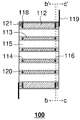
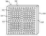
- FIG. 1 is a schematic perspective view of a heater element according to an embodiment of the present invention.
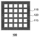
- FIG. 2 is a cross-sectional view taken along the line aa'in the heater element of FIG.
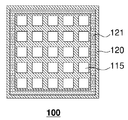
- FIG. 3 is a cross-sectional view taken along the line bb'in the heater element of FIG.
- FIG. 4 is a cross-sectional view taken along the line cc'in the heater element of FIG.
- the heater element 100 according to the embodiment of the present invention is arranged inside the outer peripheral wall 112 and the outer peripheral wall 112, and forms a plurality of cells 115 that form a flow path from the first end surface 114 to the second end surface 116.
- a columnar honeycomb structure having a partition wall 113 is provided.
- the heater element 100 further includes a dense insulating film 120 that covers at least a part of the columnar honeycomb structure portion.
- the perspective view of FIG. 1 shows, as an example, a case where the entire columnar honeycomb structure is covered with a dense insulating film 120.
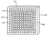
- the columnar honeycomb structure has, for example, a columnar end face (first end face 114 and second end face 116) having a polygonal shape (square (rectangular, square), pentagon, hexagon, heptagon, octagon, etc.) and a circular end face. It can have any shape such as a columnar shape (cylindrical shape) and a columnar shape having an oval end face. If the end face is polygonal, the corners may be chamfered.
- the columnar honeycomb structure shown in FIGS. 5 and 6 described later has a chamfered rectangular end face.
- the shape of the cell 115 in the cross section orthogonal to the flow path direction of the cell 115 is preferably a quadrangle (rectangle, square), a hexagon, an octagon, or a combination of two or more of these. Of these, squares and hexagons are preferred.
- the shape of the cell 115 such a shape, it is possible to reduce the pressure loss when gas is passed through the columnar honeycomb structure portion.
- the shape of the cell 115 in the cross section orthogonal to the flow path direction of the cell 115 is square.
- the area of each end face of the columnar honeycomb structure is preferably 50 cm 2 or more, more preferably 70 cm 2 or more, and even more preferably 100 cm 2 or more.
- the area of each bottom surface of the columnar honeycomb structure portion preferably to 500 cm 2 or less, more preferably, to 300 cm 2 or less, still more to 200 cm 2 or less Even more preferable.
- the area of each end face of the columnar honeycomb structure can be , for example, 50 to 500 cm 2.
- the length of the columnar honeycomb structure (flow path length of each cell 115) is preferably, for example, 40 mm or less, more preferably 30 mm or less, and 20 mm or less. It is more preferably 10 mm or less, and even more preferably 10 mm or less. From the viewpoint of ensuring heating performance and strength, the length of the columnar honeycomb structure (flow path length of each cell 115) is preferably 3 mm or more. The length of the columnar honeycomb structure (the length of the flow path of each cell 115) can be, for example, 3 to 40 mm.
- the outer peripheral wall 112 and the partition wall 113 of the columnar honeycomb structure are made of a material capable of generating heat by energization. Therefore, a gas such as outside air or vehicle interior air flows in from the first end surface 114, passes through the plurality of cells 115, and flows out from the second end surface 116. It can be heated by heat transfer from the partition wall 113.
- the outer peripheral wall 112 and the partition wall 113 are made of a material having PTC (Positive Temperature Coefficient) characteristics. That is, the outer peripheral wall 112 and the partition wall 113 have a characteristic that when the temperature rises and exceeds the Curie point, the resistance value rapidly rises and it becomes difficult for electricity to flow. Since the outer peripheral wall 112 and the partition wall 113 have PTC characteristics, when the heater element 100 becomes hot, the current flowing through them is limited, so that excessive heat generation of the heater element 100 is prevented.
- PTC Pressure Temperature Coefficient
- the outer peripheral wall 112 and the partition wall 113 are preferably ceramics made of a material containing barium titanate as a main component, and 70 mass of barium titanate is used. It is more preferable that the ceramic is made of a material containing% or more, and even more preferably the ceramic is made of a material containing 90% by mass or more of barium titanate. It is preferable that the ceramics contain one or more additives such as rare earth elements in order to obtain desired PTC characteristics.
- Additives include semiconductor agents such as Y, La, Ce, Pr, Nd, Sm, Eu, Gd, Tb, Dy, Ho, Er, Tm, Yb and Lu, and low temperatures such as Sr, Sn and Zr. Side shifters, high temperature shifters such as (Bi-Na), (Bi-K), property improvers such as Mn, metal oxides such as vanadium oxide and ytterbium oxide (especially oxides of rare earth elements). , And conductor powders such as carbon black and nickel.
- Other PTC materials include composite materials containing cristobalite phase SiO 2 as a base material and a conductive filler. Alternatively the tridymite phase SiO 2 of cristobalite phase SiO 2 base material, cristobalite phase AlPO 4, can also be used tridymite phase AlPO 4.
- the Curie point of the material constituting the outer peripheral wall 112 and the partition wall 113 is preferably 100 ° C. or higher, more preferably 110 ° C. or higher, and 125 ° C. or higher from the viewpoint of efficiently heating air for heating. It is even more preferable to have. Further, the Curie point of the material constituting the outer peripheral wall 112 and the partition wall 113 is preferably 250 ° C. or lower, preferably 225 ° C. or lower, from the viewpoint of safety as a component placed in the passenger compartment or in the vicinity of the passenger compartment. Is more preferable, 200 ° C. or lower is even more preferable, and 150 ° C. or lower is particularly preferable.
- the Curie point of the material constituting the outer peripheral wall 112 and the partition wall 113 is related to the type of the insulating film 120 covering the outer peripheral wall 112 and the partition wall 113. Details will be described below.
- the Curie points of the materials constituting the outer peripheral wall 112 and the partition wall 113 can be adjusted by the type of shifter and the amount of addition.
- the Curie point of barium titanate (BaTIO 3 ) is about 120 ° C., but the Curie point is shifted to the low temperature side by substituting a part of Ba and Ti with one or more of Sr, Sn and Zr. Can be done. Further, by substituting a part of Ba with Pb, the Curie temperature can be shifted to the high temperature side.
- the Curie point is measured by the following method.
- the sample is attached to a sample holder for measurement, mounted in a measuring tank (eg, MINI-SUBZERO MC-810P, manufactured by Tabai Espec), and the change in electrical resistance of the sample with respect to the temperature change when the temperature rises from 10 ° C. , Measured using a DC resistance meter (eg, multimeter 3478A, manufactured by YHP).
- a DC resistance meter eg, multimeter 3478A, manufactured by YHP
- the average thickness of the partition wall 113 in the honeycomb structure portion is preferably 0.13 mm or less, more preferably 0.10 mm or less, and even more preferably 0.08 mm or less.
- the average thickness of the partition wall 113 is preferably 0.02 mm or more, more preferably 0.04 mm or more, and more preferably 0.06 mm or more. Is even more preferable.
- the thickness of the partition wall 113 refers to the length at which the line segment crosses the partition wall 113 when the centers of gravity of adjacent cells 115 are connected by a line segment in a cross section orthogonal to the flow path direction of the cell 115. ..
- the average thickness of the partition wall 113 refers to an average value when the thickness of the partition wall 113 is measured at 10 points.
- the strength of the columnar honeycomb structure tends to decrease. Therefore, the strength can be supplemented by providing the partition wall A having a large thickness of the partition wall 113 and the partition wall B having a small thickness of the partition wall 113.
- the partition wall 113 forming the outermost cell group is at least thick.
- the average thickness of the partition wall 113 is preferably 0.12 mm or more, preferably 0.12 mm or more, while maintaining the above range.
- FIGS. 5 and 6 show an example of a columnar honeycomb structure portion in which a portion having a large thickness of the partition wall 113 is partially provided.
- the same reference numerals as those shown in FIGS. 1 to 4 are the same as those in FIGS. 1 to 4, so the description thereof will be omitted.
- the partition wall 113 for partitioning the outermost cell group and the partition wall 113 for partitioning the outermost cell group excluding the cell group are more than the other partition walls 113. Is getting thicker.
- a group of cells arranged in a cross shape is formed through the center of the end face of the columnar honeycomb structure.
- the partition wall 113 is also thicker than the other partition walls 113.
- the strength of the columnar honeycomb structure can be supplemented by increasing the thickness of the outer peripheral wall 112.
- the thickness of the outer peripheral wall 112 is preferably 0.05 mm or more, more preferably 0.06 mm or more, and even more preferably 0.08 mm or more. preferable.
- the thickness of the outer peripheral wall 112 is preferably 1 mm or less, preferably 0.5 mm or less. Is even more preferable, 0.4 mm or less is even more preferable, and 0.3 mm or less is even more preferable.
- the thickness of the outer peripheral wall 112 is the thickness of the outer peripheral wall 112 from the boundary between the outer peripheral side wall and the outermost cell 115 or the partition wall 113 to the side surface of the columnar honeycomb structure in the cross section orthogonal to the flow path of the cell 115. Refers to the length in the normal direction.
- the aperture ratio (OFA) is large. Therefore, the aperture ratio at each end face of the honeycomb structure is preferably 0.81 or more, more preferably 0.83 or more, and even more preferably 0.85 or more. Further, by increasing the aperture ratio (OFA), it is possible to further suppress the ventilation resistance. However, from the viewpoint of ensuring the strength of the honeycomb structure, the aperture ratio at each end face of the honeycomb structure is preferably 0.92 or less, more preferably 0.90 or less, and 0.88 or less. Is even more preferable.
- the aperture ratio at each end face of the columnar honeycomb structure refers to the ratio of the area of the opening of the cell 115 at the end face to the area of each end face including the opening of the cell 115.
- the columnar honeycomb structure preferably has a cell density of 93 cells / cm 2 or less, and more preferably 90 cells / cm 2 or less. By controlling the cell density within such a range, the ventilation resistance can be suppressed and the output of the blower can be suppressed.
- the columnar honeycomb structure preferably has a cell density of 60 cells / cm 2 or more, and more preferably 80 cells / cm 2 or more. By restricting the cell density to the above range in combination with the above-mentioned preferable range of the average thickness of the partition wall 113, it is possible to obtain a columnar honeycomb structure suitable for rapid heating while suppressing the initial current.
- the cell density of the columnar honeycomb structure is a value obtained by dividing the number of cells by the area of each end face of the columnar honeycomb structure.
- the upper limit of h ⁇ S is preferably 80 W / K or less, and preferably 75 W / K or less. More preferably, it is 70 W / K or less, and even more preferably.
- the apparent heat transfer coefficient h is calculated by the following formula (1).
- h (Nu / d) ⁇ ⁇ ⁇ ⁇ ⁇ (1)
- Nu is a fixed value of 3.63
- d is the hydraulic diameter (m) of the cell 115
- ⁇ is the thermal conductivity of air (W / m / K)
- ⁇ 2.5. It is set to ⁇ 10 -2 .
- the total surface area S is calculated by the following formula (2).
- S GSA x V ... (2)
- V indicates the volume of the columnar honeycomb structure (m 3 )
- GSA indicates the surface area per volume of the columnar honeycomb structure (m 2 / m 3 )
- GSA is based on the following formula (3). Desired.
- GSA ⁇ 4 (Pt) x Li ⁇ / ⁇ Li x P 2 ⁇ ... (3)
- Li indicates the unit length (1 m)
- P indicates the average cell pitch (m)
- t indicates the average thickness (m) of the partition wall 113.
- the volume of the columnar honeycomb structure refers to a volume value measured based on the external dimensions of the columnar honeycomb structure.
- the average cell pitch (P) refers to a value obtained by the following calculation. First, the area of the end face of the columnar honeycomb structure portion excluding the outer peripheral wall 112 is divided by the number of cells 115 to calculate the area per cell. Next, the square root of the area per cell is calculated, and this is used as the average cell pitch.
- the average thickness of the partition wall 113 is as described above.
- the columnar honeycomb structure can be used as a complex in which two or more are joined by the outer peripheral walls 112.
- By joining a plurality of small columnar honeycomb structure portions to form a large complex it is possible to increase the total cross-sectional area of the cell 115, which is important for securing the gas flow rate while suppressing the occurrence of cracks.
- a schematic end view of an example of such a composite of columnar honeycomb structures is shown in FIG. In FIG. 7, four columnar honeycomb structure portions A to D having substantially square end faces and the same size are joined to each other by joining two outer peripheral walls 112 to each other via a joining material 117 in the vertical and horizontal directions.
- the joining material 117 for joining the outer peripheral walls 112 of the columnar honeycomb structure portions A to D is not limited, but a ceramic material to which a solvent such as water is added to form a paste can be used. ..
- the bonding material 117 may contain ceramics having PTC characteristics, or may contain the same ceramics as the outer peripheral wall 112 and the partition wall 113.
- the joining material 117 can also be used as an outer peripheral coating material for the entire large composite after joining the columnar honeycomb structure portions A to D.
- the dense insulating film 120 plays a role of suppressing a short circuit of the electric circuit in the heater element 100 when moisture such as dew condensation water adheres to the heater element 100.
- the dense insulating film 120 may cover a portion to which moisture such as condensed water adheres.
- the dense insulating film 120 preferably covers at least one selected from the outer surface of the outer peripheral wall 112 of the columnar honeycomb structure, the surface of the flow path, the first end surface 114 and the second end surface 116.
- the dense insulating film 120 refers to the insulating film 120 having a small porosity.
- the porosity of the insulating film 120 is preferably 5% or less, preferably 4% or less, and preferably 3% or less. If the porosity is in such a range, it is possible to stably suppress the passage of water through the insulating film 120.
- the dense insulating film 120 is formed of an insulating material.
- the material having insulating properties is not particularly limited, and for example, resins (polyimide resin, polyamide resin, polyamide-imide resin, fluororesin, phenol resin, silicone resin, epoxy resin, furan resin, polyvinylidene fluoride, polyphenylene sulfide, etc. Polyetherimide, polysulfone, polyamideimide, etc.), glass, ceramics, etc. can be used. Examples of ceramics include alumina, mullite, and spinel.
- the outer peripheral wall 112 and the partition wall 113 are made of a material having a Curie point of 150 ° C. or lower, the level of heat resistance required for the dense insulating film 120 becomes low. Therefore, it is possible to select a resin as the material of the dense insulating film 120.
- a resin a fluororesin such as polytetrafluoroethylene or a polyimide resin is preferable from the viewpoint of insulating property and heat resistance.
- the outer peripheral wall 112 and the partition wall 113 are made of a material having a Curie point of more than 150 ° C., the level of heat resistance required for the dense insulating film 120 becomes high. Therefore, it is preferable to select glass or ceramics as the material of the dense insulating film 120.
- the average thickness of the dense insulating film 120 is preferably 100 ⁇ m or less, more preferably 50 ⁇ m or less, and even more preferably 10 ⁇ m or less. By controlling the average thickness within such a range, the influence on the heat transferability to the gas is small, and the pressure loss is unlikely to increase. On the other hand, if the average thickness of the dense insulating film 120 is too small, the effect of suppressing a short circuit in the electric circuit may not be sufficiently obtained. Therefore, the average thickness of the dense insulating film 120 is preferably 0.1 ⁇ m or more, more preferably 0.5 ⁇ m or more, and even more preferably 1.0 ⁇ m or more.
- the thickness of the dense insulating film 120 refers to the base material (outer surface of the outer peripheral wall 112, the surface of the flow path) on which the dense insulating film 120 is formed in a cross section orthogonal to the flow path direction of the cell 115. Refers to the length in the direction perpendicular to the first end surface 114 and the second end surface 116).
- the average thickness of the dense insulating film 120 refers to an average value when the thickness of the insulating film 120 is measured at 10 points.
- the heater element 100 may have an electrode layer 118 on the surfaces of the outer peripheral wall 112 and the partition wall 113 on the first end surface 114 and the second end surface 116 (see FIGS. 2 and 3). It is preferable that the electrode layer 118 is provided with the electrode layer 118 on each end face without blocking the cell 115, and more preferably the electrode layer 118 is provided on the entire end face without blocking the cell 115.
- the electrode layer 118 for example, one containing at least one selected from Cu, Ag, Al and Si can be used. It is also possible to use an ohmic electrode layer capable of ohmic contact with the outer peripheral wall 112 and / or the partition wall 113 having PTC characteristics.
- the ohmic electrode layer contains, for example, at least one selected from Au, Ag and In as the base metal, and at least one selected from Ni, Si, Ge, Sn, Se and Te for n-type semiconductors as the dopant.
- the contained ohmic electrode layer can be used.
- the heater element 100 has the electrode layer 118, it is preferable that at least a part, preferably the whole of the electrode layer 118, is covered with the insulating film 120. With such a configuration, it is possible to suppress a short circuit of the electric circuit when moisture such as dew condensation water adheres to the heater element 100.
- the heater element 100 may have a conductive member 121 connectable to an external power source in at least a part of the electrode layer 118 (see FIGS. 2 and 4).
- the conductive member 121 is preferably electrically connected to the electrode layer 118. That is, it is preferable that the conductive member 121 and the electrode layer 118 are in contact with each other, and it is preferable that the insulating film 120 does not intervene on the contact surface between the conductive member 121 and the electrode layer 118.
- the conductive member 121 is preferably arranged on the electrode layer 118 provided on the outer peripheral wall 112 of the first end surface 114 and the second end surface 116. With such a configuration, the entire electrode layer 118 can be efficiently energized.
- the conductive member 121 is plate-shaped and is formed of a material having excellent conductivity.
- the conductive member 121 is formed of a metal such as a copper plate or a stainless steel plate.
- the heater element 100 has the conductive member 121, it is preferable that at least a part, preferably the whole of the conductive member 121 is covered with the insulating film 120. With such a configuration, it is possible to suppress a short circuit of the electric circuit when moisture such as dew condensation water adheres to the heater element 100.
- a part of the conductive member 121 is exposed on the surface, and the part is connected to the electric wire 119 from the external power source.
- the electric wire 119 can be connected to the conductive member 121 by diffusion bonding, a mechanical pressurizing mechanism, welding, or the like, and power can be supplied from the battery, for example, via the electric wire 119.
- the heater element 100 according to the embodiment of the present invention can generate heat by applying a voltage between a pair of electrode layers 118 arranged on each end face, for example.
- a voltage between a pair of electrode layers 118 arranged on each end face for example.
- the applied voltage from the viewpoint of rapid heating, it is preferable to apply a voltage of 200 V or more, and more preferably a voltage of 250 V or more is applied.
- the heater element 100 according to the embodiment of the present invention is highly safe because the initial current can be suppressed even when a high voltage is applied.
- the safety specifications do not become heavy, the equipment around the heater can be manufactured at low cost.
- the gas can be heated by flowing the gas through the cell 115.
- the temperature of the gas flowing into the cell 115 can be, for example, ⁇ 60 ° C. to 20 ° C., and typically ⁇ 10 ° C. to 20 ° C.
- a method for manufacturing the heater element 100 according to the embodiment of the present invention will be exemplified.
- a raw material composition containing a dispersion medium and a binder is mixed with a ceramic raw material and kneaded to prepare a clay, and then the clay is extruded to prepare a honeycomb molded product.
- Additives such as dispersants, semiconductor agents, shifters, metal oxides, property improvers, and conductor powders can be added to the raw material composition, if necessary.
- a mouthpiece having a desired overall shape, cell shape, partition wall thickness, cell density and the like can be used.
- the ceramic raw material is a raw material for a portion that remains after firing and constitutes the skeleton of the honeycomb structure as ceramics.
- the ceramic raw material can be provided, for example, in the form of powder.
- oxides and carbonate raw materials such as TiO 2 and BaCO 3, which are the main components of barium titanate, can be used.
- semiconductor agents such as Y, La, Ce, Pr, Nd, Sm, Eu, Gd, Tb, Dy, Ho, Er, Tm, Yb and Lu, and low temperature shifters such as Sr, Sn and Zr.
- the raw material powder such as TiO 2 and BaCO 3, La after adding (NH 3) 3 ⁇ 6H 2 O, further addition of dispersants and binders, BaO (50.3mol%) as a sintered body, TiO Lead-free by blending to 2 (49.6 mol%), La 2 O 3 (0.05 mol%), K 2 O (0.033 mol%), Na 2 O (0.002 mol%).
- a honeycomb structure can be obtained.
- the composition is not limited to this, and by blending the ceramics whose composition formula is represented by the following formula so as to occupy 90% by mass or more, a honeycomb structure portion containing rare earth elements and alkali metal elements and not using lead is obtained. be able to.
- A1 represents one or more rare earth elements
- A2 represents one or more alkali metal elements, 0.001 ⁇ x ⁇ 0.01, 0 ⁇ y ⁇ 0.01, 0. 001 ⁇ x + y ⁇ 0.02.
- dispersion medium examples include water or a mixed solvent of water and an organic solvent such as alcohol, and water can be particularly preferably used.
- binder examples include organic binders such as methyl cellulose, hydroxypropoxyl cellulose, hydroxyethyl cellulose, carboxymethyl cellulose, and polyvinyl alcohol. In particular, it is preferable to use methyl cellulose and hydroxypropoxyl cellulose in combination.
- the binder content is preferably 4 parts by mass or more, more preferably 5 parts by mass or more, and 6 parts by mass with respect to 100 parts by mass of the ceramic raw material from the viewpoint of increasing the strength of the honeycomb molded body. It is even more preferable that the number is more than one part.
- the binder content is preferably 9 parts by mass or less, more preferably 8 parts by mass or less, based on 100 parts by mass of the ceramic raw material, from the viewpoint of suppressing the occurrence of sharpening due to abnormal heat generation in the firing step. Even more preferably, it is 7 parts by mass or less.
- One type of binder may be used alone, or two or more types may be used in combination.
- a surfactant such as ethylene glycol, dextrin, fatty acid soap, or polyalcohol can be used.
- the dispersant may be used alone or in combination of two or more.
- the content of the dispersant is preferably 0 to 2 parts by mass with respect to 100 parts by mass of the ceramic raw material.
- the obtained honeycomb molded body is dried.
- conventionally known drying methods such as hot air drying, microwave drying, dielectric drying, vacuum drying, vacuum drying, and freeze drying can be used.
- a drying method combining hot air drying and microwave drying or dielectric drying is preferable in that the entire molded product can be dried quickly and uniformly.
- a heater element having a columnar honeycomb structure can be manufactured by firing the dried honeycomb molded body.
- a degreasing step to remove the binder can also be performed before firing.
- the firing conditions can be appropriately determined depending on the material of the honeycomb molded body. For example, when the material of the honeycomb molded product contains barium titanate as a main component, the firing temperature is preferably 1100 to 1400 ° C, more preferably 1200 to 1300 ° C.
- the firing time is preferably about 1 to 4 hours.
- the atmosphere for carrying out the degreasing step can be, for example, an atmospheric atmosphere, an inert atmosphere, or a decompressed atmosphere. Among these, it is preferable to create an inert atmosphere and a reduced pressure atmosphere that prevent insufficient sintering due to oxidation of the raw material and easily reduce the oxide contained in the raw material.
- the firing furnace is not particularly limited, but an electric furnace, a gas furnace, or the like can be used.
- the electrode layer 118 is formed on the first end surface 114 and the second end surface 116 of the columnar honeycomb structure portion thus obtained.
- the electrode layer 118 can be formed by a metal precipitation method such as sputtering, vapor deposition, electrolytic precipitation, or chemical precipitation. Further, the electrode layer 118 can also be formed by applying the electrode paste and then baking the electrode layer 118. Further, the electrode layer 118 can also be formed by thermal spraying.
- the electrode layer 118 may be a single layer, but may be a plurality of layers having different compositions.
- the thickness of the electrode layer 118 is about 5 to 30 ⁇ m for baking paste, about 100 to 1000 nm for dry plating such as sputtering and vapor deposition, about 10 to 100 ⁇ m for thermal spraying, and wet plating such as electrolytic precipitation and chemical precipitation. Then, it is preferably about 5 to 30 ⁇ m.
- the conductive member 121 is arranged and joined at a predetermined position on the electrode layer 118.
- the joining method is not particularly limited, and diffusion joining, a mechanical pressurizing mechanism, welding, or the like can be used.
- a dense insulating film 120 is formed on a predetermined surface of the columnar honeycomb structure portion in which the electrode layer 118 and the conductive member 121 are arranged.
- a method for forming the dense insulating film 120 a method known in the art may be selected according to the type of material used. Specifically, CVD, PVD, immersion coating, spray coating and the like can be used. Further, when ceramics are selected as the material of the dense insulating film 120, the ceramic film may be formed by performing a dip coating with a slurry of ceramic raw materials and then performing a heat treatment.
- FIG. 8 is a schematic view showing a configuration example of a vehicle interior heating heater according to an embodiment of the present invention.
- the vehicle interior heating heater 200 according to the embodiment of the present invention includes a heater element 100, an inflow pipe 132 (132a, 132b) communicating the outside air introduction unit or the vehicle interior 130 with the first end surface 114 of the heater element 100, and a heater element.
- a battery 134 for applying a voltage to the 100 and an outflow pipe 136 for communicating the second end surface 116 of the heater element 100 with the vehicle interior 130 are provided.
- the heater element 100 can be configured to energize and generate heat by connecting the battery 134 to the battery 134 with an electric wire 119 and turning on the power switch in the middle of the connection.
- a vapor compression heat pump 150 can be installed on the upstream side of the heater element 100.
- the vapor compression heat pump 150 is configured as a main heating device, and the heater element 100 is configured as an auxiliary heater.
- the vapor compression heat pump 150 includes a heat exchanger.
- the heat exchanger includes an evaporator 160 that absorbs heat from the outside during cooling and evaporates the refrigerant, and a condenser 170 that liquefies the refrigerant gas and releases heat to the outside during heating.
- dew condensation water is generated in the heat exchanger of the vapor compression heat pump 150. Condensed water scatters and adheres to the heater element 100 on the downstream side due to the flow of air.
- the heater element 100 is unlikely to cause a short circuit in the electric circuit due to condensed water, so that the heater element 100 is stably operated as an auxiliary heater. be able to.
- the vapor compression heat pump 150 is not particularly limited, and a vapor compression heat pump 150 known in the art can be used.
- a blower 138 can be installed on the upstream side or the downstream side of the heater element 100. From the viewpoint of ensuring safety by arranging the high-voltage parts as far as possible from the passenger compartment 130, it is preferable to install the blower 138 on the upstream side of the heater element 100.
- the blower 138 When the blower 138 is driven, air flows into the heater element 100 from inside the passenger compartment 130 or outside the passenger compartment 130 through the inflow pipes 132 (132a, 132b). The air is heated while passing through the heating element 100 that is generating heat. The heated air flows out from the heater element 100 and is sent into the passenger compartment 130 through the outflow pipe 136.
- the outlet of the outflow pipe 136 may be arranged near the feet of the occupant so that the heating effect is particularly high even in the passenger compartment 130, or the pipe outlet may be arranged in the seat to warm the seat from the inside. Alternatively, it may be arranged near the window to have the effect of suppressing fogging of the window.
- the vehicle interior heating heater 200 includes an inflow pipe 132a that communicates the outside air introduction portion and the first end surface 114 of the heater element 100. Further, the vehicle interior heating heater 200 includes an inflow pipe 132b that communicates the vehicle interior 130 with the first end surface 114 of the heater element 100. The inflow pipe 132a and the inflow pipe 132b merge in the middle. Valves 139 (139a, 139b) can be installed in the inflow pipe 132a and the inflow pipe 132b on the upstream side of the confluence.
- valves 139 By controlling the opening and closing of the valves 139 (139a and 139b), it is possible to switch between a mode in which the outside air is introduced into the heater element 100 and a mode in which the air inside the passenger compartment 130 is introduced into the heater element 100. For example, when the valve 139a is opened and the valve 139b is closed, the mode is set to introduce the outside air into the heater element 100. It is also possible to open both the valve 139a and the valve 139b to simultaneously introduce the outside air and the air inside the passenger compartment 130 into the heater element 100.
- Heater element 112 Outer wall 113 Barrier 114 First end surface 115 Cell 116 Second end surface 117 Joint material 118 Electrode layer 119 Electric wire 120 Insulation film 121 Conductive member 130 Vehicle interior 139 (139a, 139b) Valve 132 (132a, 132b) Inflow piping 134 Battery 136 Outflow piping 138 Blower 150 Vapor-compression heat pump 160 Evaporator 170 Condenser 200 Heater for room heating
Abstract
The purpose of the present invention is to provide: a heater element for heating a vehicle interior, the heater element being on in which a PTC material is used, wherein it is possible to minimize short-circuiting of an electric circuit due to moisture such as condensed water; and a heater for heating a vehicle interior, the heater comprising such a heater element for heating a vehicle interior. A heater element (100) for heating the interior of a vehicle, the heater element (100) comprising a pillared honeycomb structure section having: an outer peripheral wall (112); and a dividing wall (113) that is placed on the inner side of the outer peripheral wall (112) and that, by sectioning, forms a plurality of cells (115) that form flow channels from a first end surface (114) to a second end surface (116). The outer peripheral wall (112) and the dividing wall (113) are configured from a material having PTC characteristics. The heater element (100) for heating a vehicle interior furthermore comprises a fine insulating film (120) that covers at least part of the pillared honeycomb structure section.
Description
本発明は、車室暖房用ヒーターエレメント及び車室暖房用ヒーターに関する。
The present invention relates to a heater element for heating a passenger compartment and a heater for heating a passenger compartment.
地球環境保護の観点から、自動車からのCO2排出量の低減要求が高まっている。また、都市部での環境基準達成の観点から、自動車からの窒素酸化物などのゼロエミッション化要求が高まっている。これらに対応可能な対策として、電気自動車が注目されている。しかしながら、電気自動車は従来暖房の熱源としていた内燃機関を持たないので、暖房の熱源が不足するという問題がある。
From the viewpoint of protecting the global environment, there is an increasing demand for reduction of CO 2 emissions from automobiles. In addition, from the viewpoint of achieving environmental standards in urban areas, there is an increasing demand for zero emissions of nitrogen oxides and the like from automobiles. Electric vehicles are attracting attention as measures that can deal with these issues. However, since the electric vehicle does not have an internal combustion engine which has been used as a heat source for heating in the past, there is a problem that the heat source for heating is insufficient.
そこで、バッテリーの電力を有効に用いて暖房を行うために蒸気圧縮ヒートポンプが用いられてきた(特許文献1)。蒸気圧縮ヒートポンプは、媒体を電動コンプレッサーによって圧縮し、気相-液相間の相変化での吸熱及び放熱を利用して、冷たい外気から車室内へ熱をポンピングするものである。蒸気圧縮ヒートポンプは、投入電力に対し、ポンピングできる熱量が大きいので、電気エネルギーをより有効に利用できるという利点がある。
Therefore, a vapor compression heat pump has been used to perform heating by effectively using the electric power of the battery (Patent Document 1). The vapor compression heat pump compresses the medium by an electric compressor and pumps heat from the cold outside air into the vehicle interior by utilizing heat absorption and heat dissipation in the phase change between the gas phase and the liquid phase. The vapor compression heat pump has an advantage that electric energy can be used more effectively because the amount of heat that can be pumped is large with respect to the input power.
また、通電時の電気抵抗により発生するジュール熱を利用したヒーターも知られている(特許文献2)。ジュール熱を利用したヒーターでは、発熱体が熱交換器に配置されており、熱交換器を通過する流体が加熱される。ジュール熱を利用したヒーターは、車両始動時の急速加熱が必要なときや外気温が非常に低い時に有効である。発熱体としては、熱暴走を防止するためPTC材料を用いることが知られている。
A heater that utilizes Joule heat generated by electrical resistance when energized is also known (Patent Document 2). In a heater using Joule heat, a heating element is arranged in a heat exchanger, and a fluid passing through the heat exchanger is heated. A heater using Joule heat is effective when rapid heating is required at the start of the vehicle or when the outside air temperature is very low. As the heating element, it is known to use a PTC material in order to prevent thermal runaway.
一方で、ハニカム状のヒーターエレメントを用いたヒーター(以下、「ハニカムヒーター」という。)が知られている。例えば、特許文献3には、チタン酸バリウム系のPTCサーミスタを利用したハニカム状発熱体が、温風暖房機、乾燥機、ヘアドライヤなどの分野に使用されることが記載されている。また、特許文献4には、ガソリンエンジン、ディーゼルエンジン及び燃焼装置からの排ガスを加熱するのに有効な通電発熱用ハニカム構造体が記載されている。さらに、特許文献5においても、内燃機関の排ガスを処理するための電気加熱可能なハニカム体が記載されている。
On the other hand, a heater using a honeycomb-shaped heater element (hereinafter referred to as "honeycomb heater") is known. For example, Patent Document 3 describes that a honeycomb-shaped heating element using a barium titanate-based PTC thermistor is used in fields such as a hot air heater, a dryer, and a hair dryer. Further, Patent Document 4 describes a honeycomb structure for energizing heat generation which is effective for heating exhaust gas from a gasoline engine, a diesel engine and a combustion device. Further, Patent Document 5 also describes an electrically heatable honeycomb body for treating the exhaust gas of an internal combustion engine.
熱効率の観点からは蒸気圧縮ヒートポンプが優れているが、蒸気圧縮ヒートポンプは外気が極低温の時に作動が困難であること、及び車両始動時に急速に車室を温めることが困難であるといった問題がある。そこで、蒸気圧縮ヒートポンプを主たる暖房装置として使用しつつ、車両始動時の急速加熱が必要なときや外気温が非常に低い時に、ジュール熱を利用したヒーターを補助的に活用することは実用的であると考えられる。
The steam compression heat pump is superior from the viewpoint of thermal efficiency, but the steam compression heat pump has problems that it is difficult to operate when the outside air is extremely low temperature and it is difficult to quickly heat the passenger compartment when the vehicle is started. .. Therefore, while using the vapor compression heat pump as the main heating device, it is practical to use a heater that uses Joule heat as a supplement when rapid heating is required at the start of the vehicle or when the outside temperature is extremely low. It is believed that there is.
しかしながら、従来のジュール熱を利用したヒーターは、大型化し易く、車内スペースを圧迫するという問題がある。このため、よりコンパクトなヒーターが提供されることが望ましい。この点、ハニカムヒーターは体積当たりの熱伝達面積を大きくすることができるため、ヒーターの小型化に資すると考えられる。しかしながら、特許文献4に記載の通電発熱用ハニカム構造体は、ハニカム構造体がNTC特性を有するため、過剰に発熱してしまい、車室暖房用ヒーターとしては適応し難い。また、特許文献5に記載の技術では、PTC材料からなる制御要素の温度がハニカム体の温度に追随せず、車室暖房用ヒーターとしては、過剰発熱の抑制効果が十分といえるものではない。これに対して、特許文献3に記載のPTCサーミスタを利用したハニカム状発熱体は、過剰な発熱を抑制できるため、車室暖房用ヒーターに適用できる可能性がある。
However, the conventional heater using Joule heat tends to be large and has a problem of squeezing the space inside the vehicle. Therefore, it is desirable to provide a more compact heater. In this respect, the honeycomb heater can increase the heat transfer area per volume, which is considered to contribute to the miniaturization of the heater. However, since the honeycomb structure for energizing heat generation described in Patent Document 4 has NTC characteristics, it generates excessive heat, and it is difficult to adapt it as a heater for heating a vehicle interior. Further, in the technique described in Patent Document 5, the temperature of the control element made of the PTC material does not follow the temperature of the honeycomb body, and it cannot be said that the effect of suppressing excessive heat generation is sufficient for the heater for heating the passenger compartment. On the other hand, the honeycomb-shaped heating element using the PTC thermistor described in Patent Document 3 can suppress excessive heat generation, and therefore may be applicable to a heater for heating a vehicle interior.
一方、蒸気圧縮ヒートポンプを主暖房装置として使用する車室暖房用ヒーターにハニカムヒーターを配置する場合、上流側に蒸気圧縮ヒートポンプの熱交換器(凝縮器及び蒸発器)が存在するため、熱交換器で発生する結露水がハニカムヒーターに飛散して付着することがある。したがって、特許文献3に記載のハニカム状発熱体を車室暖房用ヒーターに用いる場合、ハニカムヒーターの電気回路が結露水によって短絡する恐れがあることから、この問題を改善する必要があった。
On the other hand, when the honeycomb heater is placed in the passenger compartment heating heater that uses the steam compression heat pump as the main heating device, the heat exchanger (condenser and evaporator) of the steam compression heat pump exists on the upstream side, so that the heat exchanger is used. Condensation water generated in the above may be scattered and adhered to the honeycomb heater. Therefore, when the honeycomb-shaped heating element described in Patent Document 3 is used for the heater for heating the passenger compartment, the electric circuit of the honeycomb heater may be short-circuited by the dew condensation water, so that this problem needs to be improved.
本発明は、上記のような問題を解決するためになされたものであり、PTC材料を用いたヒーターエレメントにおいて、結露水などの水分による電気回路の短絡を抑制することが可能な車室暖房用ヒーターエレメント、及びこのような車室暖房用ヒーターエレメントを備えた車室暖房用ヒーターを提供することを目的とする。
The present invention has been made to solve the above-mentioned problems, and is for heating a passenger compartment in a heater element using a PTC material, which can suppress a short circuit of an electric circuit due to moisture such as dew condensation water. It is an object of the present invention to provide a heater element and a heater for heating a passenger compartment provided with such a heater element for heating a passenger compartment.
上記課題は、以下の本発明によって解決されるものである。本発明は以下のように特定される。
The above problem is solved by the following invention. The present invention is specified as follows.
すなわち、本発明は、外周壁と、外周壁の内側に配設され、第1端面から第2端面まで流路を形成する複数のセルを区画形成する隔壁とを有する柱状ハニカム構造部を備える、車両の車室暖房用ヒーターエレメントであって、
前記外周壁及び前記隔壁がPTC特性を有する材料で構成されており、
前記柱状ハニカム構造部の少なくとも一部を被覆する緻密な絶縁膜を更に備える、
車室暖房用ヒーターエレメントである。 That is, the present invention includes a columnar honeycomb structure having an outer peripheral wall and a partition wall arranged inside the outer peripheral wall and partitioning a plurality of cells forming a flow path from the first end surface to the second end surface. It is a heater element for heating the passenger compartment of a vehicle.
The outer peripheral wall and the partition wall are made of a material having PTC characteristics.
A dense insulating film that covers at least a part of the columnar honeycomb structure is further provided.
It is a heater element for heating the passenger compartment.
また、本発明は、前記車室暖房用ヒーターエレメント、
外気導入部又は車室と前記車室暖房用ヒーターエレメントの前記第1端面とを連通する流入配管、
前記車室暖房用ヒーターエレメントに電圧を印加するためのバッテリー、及び
前記車室暖房用ヒーターエレメントの第2端面と前記車室とを連通する流出配管
を備える車室暖房用ヒーターである。 Further, the present invention relates to the above-mentioned heater element for heating the passenger compartment.
An inflow pipe that communicates the outside air introduction unit or the passenger compartment with the first end surface of the passenger compartment heating heater element.
A vehicle interior heating heater including a battery for applying a voltage to the vehicle interior heating heater element and an outflow pipe that connects a second end surface of the vehicle interior heating heater element to the vehicle interior.
本発明によれば、PTC材料を用いたヒーターエレメントにおいて、結露水などの水分による電気回路の短絡を抑制することが可能な車室暖房用ヒーターエレメント、及びこのような車室暖房用ヒーターエレメントを備えた車室暖房用ヒーターを提供することができる。
According to the present invention, in a heater element using a PTC material, a heater element for heating a passenger compartment capable of suppressing a short circuit of an electric circuit due to moisture such as condensed water, and such a heater element for heating a passenger compartment are provided. A heater for heating the passenger compartment can be provided.
以下、本発明の実施形態について、図面を参照しながら具体的に説明する。本発明は以下の実施形態に限定されるものではなく、本発明の趣旨を逸脱しない範囲で、当業者の通常の知識に基づいて、以下の実施形態に対し変更、改良などが適宜加えられたものも本発明の範囲に入ることが理解されるべきである。
Hereinafter, embodiments of the present invention will be specifically described with reference to the drawings. The present invention is not limited to the following embodiments, and changes, improvements, etc. have been appropriately added to the following embodiments based on the ordinary knowledge of those skilled in the art without departing from the spirit of the present invention. It should be understood that things also fall within the scope of the present invention.
(1.ヒーターエレメント)
本発明の実施形態に係るヒーターエレメントは、車両の車室暖房用のヒーターエレメントとして好適に利用可能である。車両としては、限定的ではないが、自動車及び電車が挙げられる。自動車としては、限定的ではないが、ガソリン車、ディーゼル車、CNG(圧縮天然ガス)やLNG(液化天然ガス)などを用いるガス燃料車、燃料電池自動車、電気自動車及びプラグインハイブリッド自動車が挙げられる。本発明の実施形態に係るヒーターエレメントは、とりわけ電気自動車及び電車のような内燃機関を持たない車両に好適に利用可能である。 (1. Heater element)
The heater element according to the embodiment of the present invention can be suitably used as a heater element for heating the passenger compartment of a vehicle. Vehicles include, but are not limited to, automobiles and trains. Examples of automobiles include, but are not limited to, gasoline-powered vehicles, diesel-powered vehicles, gas-fueled vehicles using CNG (compressed natural gas), LNG (liquefied natural gas), fuel cell vehicles, electric vehicles, and plug-in hybrid vehicles. .. The heater element according to the embodiment of the present invention can be particularly suitably used for a vehicle having no internal combustion engine such as an electric vehicle and a train.
図1は、本発明の実施形態に係るヒーターエレメントの模式的な斜視図である。図2は、図1のヒーターエレメントにおけるa-a’線の断面図である。図3は、図2のヒーターエレメントにおけるb-b’線の断面図である。図4は、図2のヒーターエレメントにおけるc-c’線の断面図である。
本発明の実施形態に係るヒーターエレメント100は、外周壁112と、外周壁112の内側に配設され、第1端面114から第2端面116まで流路を形成する複数のセル115を区画形成する隔壁113とを有する柱状ハニカム構造部を備える。また、ヒーターエレメント100は、柱状ハニカム構造部の少なくとも一部を被覆する緻密な絶縁膜120を更に備える。なお、図1の斜視図では、一例として、柱状ハニカム構造部の全体が緻密な絶縁膜120によって被覆されている場合を示している。 FIG. 1 is a schematic perspective view of a heater element according to an embodiment of the present invention. FIG. 2 is a cross-sectional view taken along the line aa'in the heater element of FIG. FIG. 3 is a cross-sectional view taken along the line bb'in the heater element of FIG. FIG. 4 is a cross-sectional view taken along the line cc'in the heater element of FIG.
Theheater element 100 according to the embodiment of the present invention is arranged inside the outer peripheral wall 112 and the outer peripheral wall 112, and forms a plurality of cells 115 that form a flow path from the first end surface 114 to the second end surface 116. A columnar honeycomb structure having a partition wall 113 is provided. Further, the heater element 100 further includes a dense insulating film 120 that covers at least a part of the columnar honeycomb structure portion. The perspective view of FIG. 1 shows, as an example, a case where the entire columnar honeycomb structure is covered with a dense insulating film 120.
本発明の実施形態に係るヒーターエレメント100は、外周壁112と、外周壁112の内側に配設され、第1端面114から第2端面116まで流路を形成する複数のセル115を区画形成する隔壁113とを有する柱状ハニカム構造部を備える。また、ヒーターエレメント100は、柱状ハニカム構造部の少なくとも一部を被覆する緻密な絶縁膜120を更に備える。なお、図1の斜視図では、一例として、柱状ハニカム構造部の全体が緻密な絶縁膜120によって被覆されている場合を示している。 FIG. 1 is a schematic perspective view of a heater element according to an embodiment of the present invention. FIG. 2 is a cross-sectional view taken along the line aa'in the heater element of FIG. FIG. 3 is a cross-sectional view taken along the line bb'in the heater element of FIG. FIG. 4 is a cross-sectional view taken along the line cc'in the heater element of FIG.
The
(1-1.柱状ハニカム構造部)
柱状ハニカム構造部は、例えば、端面(第1端面114及び第2端面116)が多角形(四角形(長方形、正方形)、五角形、六角形、七角形、八角形など)の柱状、端面が円形の柱状(円柱形状)、端面がオーバル形状の柱状などの任意の形状とすることができる。端面が多角形の場合、角部は面取りしてもよい。なお、後述する図5及び図6に示す柱状ハニカム構造部は、面取りされた長方形状の端面を有する。 (1-1. Columnar honeycomb structure)
The columnar honeycomb structure has, for example, a columnar end face (first end face 114 and second end face 116) having a polygonal shape (square (rectangular, square), pentagon, hexagon, heptagon, octagon, etc.) and a circular end face. It can have any shape such as a columnar shape (cylindrical shape) and a columnar shape having an oval end face. If the end face is polygonal, the corners may be chamfered. The columnar honeycomb structure shown in FIGS. 5 and 6 described later has a chamfered rectangular end face.
柱状ハニカム構造部は、例えば、端面(第1端面114及び第2端面116)が多角形(四角形(長方形、正方形)、五角形、六角形、七角形、八角形など)の柱状、端面が円形の柱状(円柱形状)、端面がオーバル形状の柱状などの任意の形状とすることができる。端面が多角形の場合、角部は面取りしてもよい。なお、後述する図5及び図6に示す柱状ハニカム構造部は、面取りされた長方形状の端面を有する。 (1-1. Columnar honeycomb structure)
The columnar honeycomb structure has, for example, a columnar end face (
セル115の流路方向に直交する断面におけるセル115の形状に制限はないが、四角形(長方形、正方形)、六角形、八角形、又はこれらの二種以上の組み合わせであることが好ましい。これらの中でも、正方形及び六角形が好ましい。セル115の形状をこのような形状にすることにより、柱状ハニカム構造部にガスを流したときの圧力損失を小さくすることができる。なお、図1に示すヒーターエレメント100における柱状ハニカム構造部は、セル115の流路方向に直交する断面におけるセル115の形状は正方形である。
There is no limitation on the shape of the cell 115 in the cross section orthogonal to the flow path direction of the cell 115, but it is preferably a quadrangle (rectangle, square), a hexagon, an octagon, or a combination of two or more of these. Of these, squares and hexagons are preferred. By making the shape of the cell 115 such a shape, it is possible to reduce the pressure loss when gas is passed through the columnar honeycomb structure portion. In the columnar honeycomb structure portion of the heater element 100 shown in FIG. 1, the shape of the cell 115 in the cross section orthogonal to the flow path direction of the cell 115 is square.
ガス流量を確保するという観点から、柱状ハニカム構造部の各端面の面積は、50cm2以上とすることが好ましく、70cm2以上とすることがより好ましく、100cm2以上とすることが更により好ましい。ヒーターエレメント100をコンパクトにするという観点から、柱状ハニカム構造部の各底面の面積は、500cm2以下とすることが好ましく、300cm2以下とすることがより好ましく、更には200cm2以下とすることが更により好ましい。柱状ハニカム構造部の各端面の面積は、例えば50~500cm2とすることができる。
From the viewpoint of ensuring the gas flow rate, the area of each end face of the columnar honeycomb structure is preferably 50 cm 2 or more, more preferably 70 cm 2 or more, and even more preferably 100 cm 2 or more. From the viewpoint of the heater element 100 compact, the area of each bottom surface of the columnar honeycomb structure portion, preferably to 500 cm 2 or less, more preferably, to 300 cm 2 or less, still more to 200 cm 2 or less Even more preferable. The area of each end face of the columnar honeycomb structure can be , for example, 50 to 500 cm 2.
ヒーターエレメント100をコンパクトにするという観点から、柱状ハニカム構造部の長さ(各セル115の流路長さ)は、例えば40mm以下とすることが好ましく、30mm以下とすることがより好ましく、20mm以下とすることが更に好ましく、10mm以下とすることが更により好ましい。加熱性能及び強度を確保するという観点からは、柱状ハニカム構造部の長さ(各セル115の流路長さ)は、3mm以上とすることが好ましい。柱状ハニカム構造部の長さ(各セル115の流路長さ)は、例えば3~40mmとすることができる。
From the viewpoint of making the heater element 100 compact, the length of the columnar honeycomb structure (flow path length of each cell 115) is preferably, for example, 40 mm or less, more preferably 30 mm or less, and 20 mm or less. It is more preferably 10 mm or less, and even more preferably 10 mm or less. From the viewpoint of ensuring heating performance and strength, the length of the columnar honeycomb structure (flow path length of each cell 115) is preferably 3 mm or more. The length of the columnar honeycomb structure (the length of the flow path of each cell 115) can be, for example, 3 to 40 mm.
(1-1-1.柱状ハニカム構造部の材質)
柱状ハニカム構造部の外周壁112及び隔壁113は、通電によって発熱可能な材料から形成されている。従って、外気又は車室内空気のようなガスが、第1端面114から流入してから、複数のセル115を通過し、第2端面116から流出するまでに、当該ガスは発熱する外周壁112及び隔壁113からの伝熱によって加熱されることが可能である。 (1-1-1. Material of columnar honeycomb structure)
The outerperipheral wall 112 and the partition wall 113 of the columnar honeycomb structure are made of a material capable of generating heat by energization. Therefore, a gas such as outside air or vehicle interior air flows in from the first end surface 114, passes through the plurality of cells 115, and flows out from the second end surface 116. It can be heated by heat transfer from the partition wall 113.
柱状ハニカム構造部の外周壁112及び隔壁113は、通電によって発熱可能な材料から形成されている。従って、外気又は車室内空気のようなガスが、第1端面114から流入してから、複数のセル115を通過し、第2端面116から流出するまでに、当該ガスは発熱する外周壁112及び隔壁113からの伝熱によって加熱されることが可能である。 (1-1-1. Material of columnar honeycomb structure)
The outer
また、外周壁112及び隔壁113は、PTC(Positive Temperature Coefficient)特性を有する材料で構成されている。つまり、外周壁112及び隔壁113は、温度が上昇してキュリー点を超えると、急激に抵抗値が上昇して電気が流れ難くなるという特性を有する。外周壁112及び隔壁113がPTC特性を有することによって、ヒーターエレメント100が高温になったときに、これらに流れる電流が制限されるので、ヒーターエレメント100の過剰な発熱が防止される。
Further, the outer peripheral wall 112 and the partition wall 113 are made of a material having PTC (Positive Temperature Coefficient) characteristics. That is, the outer peripheral wall 112 and the partition wall 113 have a characteristic that when the temperature rises and exceeds the Curie point, the resistance value rapidly rises and it becomes difficult for electricity to flow. Since the outer peripheral wall 112 and the partition wall 113 have PTC characteristics, when the heater element 100 becomes hot, the current flowing through them is limited, so that excessive heat generation of the heater element 100 is prevented.
通電発熱可能であり、且つ、PTC特性を有するという観点から、外周壁112及び隔壁113は、チタン酸バリウムを主成分とする材料で構成されるセラミックスであることが好ましく、チタン酸バリウムを70質量%以上含有する材料で構成されるセラミックスであることがより好ましく、チタン酸バリウムを90質量%以上含有する材料で構成されるセラミックスであることが更により好ましい。当該セラミックスは、希土類元素などの添加物を一種以上含有することが所望のPTC特性を得る上で好ましい。添加物としては、Y、La、Ce、Pr、Nd、Sm、Eu、Gd、Tb、Dy、Ho、Er、Tm、Yb及びLuのような半導体化剤、Sr、Sn及びZrのような低温側のシフター、(Bi-Na)、(Bi-K)のような高温側のシフター、Mnのような特性改善剤、酸化バナジウム及び酸化イットリウムのような金属酸化物(特に希土類元素の酸化物)、並びにカーボンブラック及びニッケルのような導電体粉末が挙げられる。このほかのPTC材料として、クリストバライト相SiO2を母材とし導電フィラーを含む複合材がある。クリストバライト相SiO2母材の代替にトリジマイト相SiO2、クリストバライト相AlPO4、トリジマイト相AlPO4を用いることもできる。
From the viewpoint of being able to generate heat by energization and having PTC characteristics, the outer peripheral wall 112 and the partition wall 113 are preferably ceramics made of a material containing barium titanate as a main component, and 70 mass of barium titanate is used. It is more preferable that the ceramic is made of a material containing% or more, and even more preferably the ceramic is made of a material containing 90% by mass or more of barium titanate. It is preferable that the ceramics contain one or more additives such as rare earth elements in order to obtain desired PTC characteristics. Additives include semiconductor agents such as Y, La, Ce, Pr, Nd, Sm, Eu, Gd, Tb, Dy, Ho, Er, Tm, Yb and Lu, and low temperatures such as Sr, Sn and Zr. Side shifters, high temperature shifters such as (Bi-Na), (Bi-K), property improvers such as Mn, metal oxides such as vanadium oxide and ytterbium oxide (especially oxides of rare earth elements). , And conductor powders such as carbon black and nickel. Other PTC materials include composite materials containing cristobalite phase SiO 2 as a base material and a conductive filler. Alternatively the tridymite phase SiO 2 of cristobalite phase SiO 2 base material, cristobalite phase AlPO 4, can also be used tridymite phase AlPO 4.
外周壁112及び隔壁113を構成する材料のキュリー点は、暖房用に空気を効率良く加熱する観点から、100℃以上であることが好ましく、110℃以上であることがより好ましく、125℃以上であることが更により好ましい。また、外周壁112及び隔壁113を構成する材料のキュリー点は、車室又は車室近傍に置かれる部品としての安全性の観点から、250℃以下であることが好ましく、225℃以下であることがより好ましく、200℃以下であることが更により好ましく、150℃以下であることが特に好ましい。
なお、外周壁112及び隔壁113を構成する材料のキュリー点は、外周壁112及び隔壁113を被覆する絶縁膜120の種類と関係する。詳細については下記で説明する。 The Curie point of the material constituting the outerperipheral wall 112 and the partition wall 113 is preferably 100 ° C. or higher, more preferably 110 ° C. or higher, and 125 ° C. or higher from the viewpoint of efficiently heating air for heating. It is even more preferable to have. Further, the Curie point of the material constituting the outer peripheral wall 112 and the partition wall 113 is preferably 250 ° C. or lower, preferably 225 ° C. or lower, from the viewpoint of safety as a component placed in the passenger compartment or in the vicinity of the passenger compartment. Is more preferable, 200 ° C. or lower is even more preferable, and 150 ° C. or lower is particularly preferable.
The Curie point of the material constituting the outerperipheral wall 112 and the partition wall 113 is related to the type of the insulating film 120 covering the outer peripheral wall 112 and the partition wall 113. Details will be described below.
なお、外周壁112及び隔壁113を構成する材料のキュリー点は、外周壁112及び隔壁113を被覆する絶縁膜120の種類と関係する。詳細については下記で説明する。 The Curie point of the material constituting the outer
The Curie point of the material constituting the outer
外周壁112及び隔壁113を構成する材料のキュリー点は、シフターの種類及び添加量によって調整可能である。例えば、チタン酸バリウム(BaTiO3)のキュリー点は約120℃であるが、Ba及びTiの一部をSr、Sn及びZrの一種以上で置換することにより、キュリー点を低温側にシフトさせることができる。また、Baの一部をPbで置換することにより、キュリー温度を高温側にシフトさせることができる。
The Curie points of the materials constituting the outer peripheral wall 112 and the partition wall 113 can be adjusted by the type of shifter and the amount of addition. For example, the Curie point of barium titanate (BaTIO 3 ) is about 120 ° C., but the Curie point is shifted to the low temperature side by substituting a part of Ba and Ti with one or more of Sr, Sn and Zr. Can be done. Further, by substituting a part of Ba with Pb, the Curie temperature can be shifted to the high temperature side.
本発明において、キュリー点は以下の方法により測定される。試料を測定用の試料ホルダーに取りつけ、測定槽(例:MINI-SUBZERO MC-810P タバイ エスペック社製)内に装着して、10℃から昇温したときの温度変化に対する試料の電気抵抗の変化を、直流抵抗計(例:マルチメーター3478A YHP製)を用いて測定する。測定により得られた電気抵抗-温度プロットにより、抵抗値が室温(20℃)における抵抗値の2倍になるときの温度をキュリー点とする。
In the present invention, the Curie point is measured by the following method. The sample is attached to a sample holder for measurement, mounted in a measuring tank (eg, MINI-SUBZERO MC-810P, manufactured by Tabai Espec), and the change in electrical resistance of the sample with respect to the temperature change when the temperature rises from 10 ° C. , Measured using a DC resistance meter (eg, multimeter 3478A, manufactured by YHP). According to the electrical resistance-temperature plot obtained by the measurement, the temperature at which the resistance value becomes twice the resistance value at room temperature (20 ° C.) is defined as the Curie point.
(1-1-2.柱状ハニカム構造部の隔壁113の平均厚み)
初期電流を抑えるという観点からは、電流通路を小さくして電気抵抗を大きくすることが有利である。従って、ハニカム構造部における隔壁113の平均厚みは、0.13mm以下であることが好ましく、0.10mm以下であることがより好ましく、0.08mm以下であることが更により好ましい。但し、ハニカム構造部の強度を確保するという観点からは、隔壁113の平均厚みは、0.02mm以上であることが好ましく、0.04mm以上であることがより好ましく、0.06mm以上であることが更により好ましい。 (1-1-2. Average thickness ofpartition wall 113 of columnar honeycomb structure)
From the viewpoint of suppressing the initial current, it is advantageous to make the current passage smaller and increase the electric resistance. Therefore, the average thickness of thepartition wall 113 in the honeycomb structure portion is preferably 0.13 mm or less, more preferably 0.10 mm or less, and even more preferably 0.08 mm or less. However, from the viewpoint of ensuring the strength of the honeycomb structure, the average thickness of the partition wall 113 is preferably 0.02 mm or more, more preferably 0.04 mm or more, and more preferably 0.06 mm or more. Is even more preferable.
初期電流を抑えるという観点からは、電流通路を小さくして電気抵抗を大きくすることが有利である。従って、ハニカム構造部における隔壁113の平均厚みは、0.13mm以下であることが好ましく、0.10mm以下であることがより好ましく、0.08mm以下であることが更により好ましい。但し、ハニカム構造部の強度を確保するという観点からは、隔壁113の平均厚みは、0.02mm以上であることが好ましく、0.04mm以上であることがより好ましく、0.06mm以上であることが更により好ましい。 (1-1-2. Average thickness of
From the viewpoint of suppressing the initial current, it is advantageous to make the current passage smaller and increase the electric resistance. Therefore, the average thickness of the
本発明において、隔壁113の厚みとは、セル115の流路方向に直交する断面において、隣接するセル115の重心同士を線分で結んだときに当該線分が隔壁113を横切る長さを指す。隔壁113の平均厚みは、隔壁113の厚みを10点測定したときの平均値を指す。
In the present invention, the thickness of the partition wall 113 refers to the length at which the line segment crosses the partition wall 113 when the centers of gravity of adjacent cells 115 are connected by a line segment in a cross section orthogonal to the flow path direction of the cell 115. .. The average thickness of the partition wall 113 refers to an average value when the thickness of the partition wall 113 is measured at 10 points.
隔壁113の厚みを薄くしていくと、柱状ハニカム構造部の強度が低下し易い。そこで、隔壁113の厚みが大きな隔壁Aと、隔壁113の厚みが小さな隔壁Bとを設けることで強度を補うこともできる。柱状ハニカム構造部を補強するという観点からは、最も外周側のセル群を形成する隔壁113は少なくとも厚くすることが好ましい。例えば、隔壁113の平均厚みとしては上述した範囲を維持しつつ、一部の隔壁A(例えば、全隔壁数の60%以内、好ましくは10%~30%)の厚みを0.12mm以上、好ましくは0.15mm以上、より好ましくは0.18mm以上、例えば0.12~0.18mm、典型的には0.15~0.18mmとし、残りの隔壁Bの厚みを0.10mm以下、好ましくは0.08mm以下、より好ましくは0.06mm以下、例えば0.05~0.10mm、典型的には0.05~0.08mmとすることができる。
As the thickness of the partition wall 113 is reduced, the strength of the columnar honeycomb structure tends to decrease. Therefore, the strength can be supplemented by providing the partition wall A having a large thickness of the partition wall 113 and the partition wall B having a small thickness of the partition wall 113. From the viewpoint of reinforcing the columnar honeycomb structure, it is preferable that the partition wall 113 forming the outermost cell group is at least thick. For example, the average thickness of the partition wall 113 is preferably 0.12 mm or more, preferably 0.12 mm or more, while maintaining the above range. Is 0.15 mm or more, more preferably 0.18 mm or more, for example 0.12 to 0.18 mm, typically 0.15 to 0.18 mm, and the thickness of the remaining partition wall B is 0.10 mm or less, preferably 0.10 mm or more. It can be 0.08 mm or less, more preferably 0.06 mm or less, for example, 0.05 to 0.10 mm, typically 0.05 to 0.08 mm.
ここで、部分的に隔壁113の厚みが大きい箇所を設けた柱状ハニカム構造部の一例を図5及び図6に示す。図5及び図6において、図1~4に示されている符号と同一の符号は、それぞれ図1~4と同様の説明が当てはまるので、説明を省略する。図5に示す柱状ハニカム構造部においては、最も外周側のセル群を区画形成する隔壁113と、当該セル群を除いて最も外周側のセル群を区画形成する隔壁113が、他の隔壁113よりも厚くなっている。図6に示す柱状ハニカム構造部においては、図5の柱状ハニカム構造部で説明した隔壁113に加えて、柱状ハニカム構造部の端面の中心を通って十文字状に配列されたセル群を区画形成する隔壁113も、他の隔壁113より厚くなっている。
Here, FIGS. 5 and 6 show an example of a columnar honeycomb structure portion in which a portion having a large thickness of the partition wall 113 is partially provided. In FIGS. 5 and 6, the same reference numerals as those shown in FIGS. 1 to 4 are the same as those in FIGS. 1 to 4, so the description thereof will be omitted. In the columnar honeycomb structure shown in FIG. 5, the partition wall 113 for partitioning the outermost cell group and the partition wall 113 for partitioning the outermost cell group excluding the cell group are more than the other partition walls 113. Is getting thicker. In the columnar honeycomb structure shown in FIG. 6, in addition to the partition wall 113 described in the columnar honeycomb structure of FIG. 5, a group of cells arranged in a cross shape is formed through the center of the end face of the columnar honeycomb structure. The partition wall 113 is also thicker than the other partition walls 113.
上記の補強方法に加えて、又は上記の補強方法に代えて、外周壁112の厚みを大きくすることによって柱状ハニカム構造部の強度を補うこともできる。柱状ハニカム構造部を補強するという観点からは、外周壁112の厚みは、0.05mm以上であることが好ましく、0.06mm以上であることがより好ましく、0.08mm以上であることが更により好ましい。ただし、電気抵抗を大きくし、初期電流を抑える観点、及びガス通過時の圧力損失を低減する観点からは、外周壁112の厚みは、1mm以下であることが好ましく、0.5mm以下であることがより好ましく、0.4mm以下であることが更により好ましく、0.3mm以下であることが更により好ましい。
In addition to the above reinforcement method, or in place of the above reinforcement method, the strength of the columnar honeycomb structure can be supplemented by increasing the thickness of the outer peripheral wall 112. From the viewpoint of reinforcing the columnar honeycomb structure, the thickness of the outer peripheral wall 112 is preferably 0.05 mm or more, more preferably 0.06 mm or more, and even more preferably 0.08 mm or more. preferable. However, from the viewpoint of increasing the electric resistance and suppressing the initial current and reducing the pressure loss when the gas passes, the thickness of the outer peripheral wall 112 is preferably 1 mm or less, preferably 0.5 mm or less. Is even more preferable, 0.4 mm or less is even more preferable, and 0.3 mm or less is even more preferable.
本発明において、外周壁112の厚みは、セル115の流路に直交する断面において、外周側壁と最も外周側のセル115又は隔壁113との境界から柱状ハニカム構造部の側面までの、当該側面の法線方向の長さを指す。
In the present invention, the thickness of the outer peripheral wall 112 is the thickness of the outer peripheral wall 112 from the boundary between the outer peripheral side wall and the outermost cell 115 or the partition wall 113 to the side surface of the columnar honeycomb structure in the cross section orthogonal to the flow path of the cell 115. Refers to the length in the normal direction.
(1-1-3.柱状ハニカム構造部の開口率)
初期電流を抑えるという観点から、開口率(OFA)は大きいほうが有利である。従って、ハニカム構造部の各端面における開口率は、0.81以上であることが好ましく、0.83以上であることがより好ましく、0.85以上であることが更により好ましい。また、開口率(OFA)を大きくすることにより、通風抵抗をより抑えることが可能である。但し、ハニカム構造部の強度を確保するという観点からは、ハニカム構造部の各端面における開口率は0.92以下であることが好ましく、0.90以下であることがより好ましく、0.88以下であることが更により好ましい。 (1-1-3. Opening ratio of columnar honeycomb structure)
From the viewpoint of suppressing the initial current, it is advantageous that the aperture ratio (OFA) is large. Therefore, the aperture ratio at each end face of the honeycomb structure is preferably 0.81 or more, more preferably 0.83 or more, and even more preferably 0.85 or more. Further, by increasing the aperture ratio (OFA), it is possible to further suppress the ventilation resistance. However, from the viewpoint of ensuring the strength of the honeycomb structure, the aperture ratio at each end face of the honeycomb structure is preferably 0.92 or less, more preferably 0.90 or less, and 0.88 or less. Is even more preferable.
本発明において、柱状ハニカム構造部の各端面における開口率は、セル115の開口部を含む各端面の面積に対する当該端面におけるセル115の開口部の面積の比率を指す。
In the present invention, the aperture ratio at each end face of the columnar honeycomb structure refers to the ratio of the area of the opening of the cell 115 at the end face to the area of each end face including the opening of the cell 115.
(1-1-4.柱状ハニカム構造部のセル密度)
柱状ハニカム構造部は、セル密度が93セル/cm2以下であることが好ましく、90セル/cm2以下であることがより好ましい。このような範囲にセル密度を制御することにより、通風抵抗を抑えて送風機の出力を抑制することができる。また、柱状ハニカム構造部は、セル密度が60セル/cm2以上であることが好ましく、80セル/cm2以上であることがより好ましい。先述した隔壁113の平均厚みの好適な範囲と組み合わせてセル密度を上記範囲に規制することで、初期電流を抑えながら、急速加熱に適した柱状ハニカム構造部とすることができる。
なお、本発明において、柱状ハニカム構造部のセル密度は、柱状ハニカム構造部の各端面の面積でセル数を除して得られる値である。 (1-1-4. Cell density of columnar honeycomb structure)
The columnar honeycomb structure preferably has a cell density of 93 cells / cm 2 or less, and more preferably 90 cells / cm 2 or less. By controlling the cell density within such a range, the ventilation resistance can be suppressed and the output of the blower can be suppressed. The columnar honeycomb structure preferably has a cell density of 60 cells / cm 2 or more, and more preferably 80 cells / cm 2 or more. By restricting the cell density to the above range in combination with the above-mentioned preferable range of the average thickness of thepartition wall 113, it is possible to obtain a columnar honeycomb structure suitable for rapid heating while suppressing the initial current.
In the present invention, the cell density of the columnar honeycomb structure is a value obtained by dividing the number of cells by the area of each end face of the columnar honeycomb structure.
柱状ハニカム構造部は、セル密度が93セル/cm2以下であることが好ましく、90セル/cm2以下であることがより好ましい。このような範囲にセル密度を制御することにより、通風抵抗を抑えて送風機の出力を抑制することができる。また、柱状ハニカム構造部は、セル密度が60セル/cm2以上であることが好ましく、80セル/cm2以上であることがより好ましい。先述した隔壁113の平均厚みの好適な範囲と組み合わせてセル密度を上記範囲に規制することで、初期電流を抑えながら、急速加熱に適した柱状ハニカム構造部とすることができる。
なお、本発明において、柱状ハニカム構造部のセル密度は、柱状ハニカム構造部の各端面の面積でセル数を除して得られる値である。 (1-1-4. Cell density of columnar honeycomb structure)
The columnar honeycomb structure preferably has a cell density of 93 cells / cm 2 or less, and more preferably 90 cells / cm 2 or less. By controlling the cell density within such a range, the ventilation resistance can be suppressed and the output of the blower can be suppressed. The columnar honeycomb structure preferably has a cell density of 60 cells / cm 2 or more, and more preferably 80 cells / cm 2 or more. By restricting the cell density to the above range in combination with the above-mentioned preferable range of the average thickness of the
In the present invention, the cell density of the columnar honeycomb structure is a value obtained by dividing the number of cells by the area of each end face of the columnar honeycomb structure.
(1-1-5.柱状ハニカム構造部のガスへの熱伝達率)
みかけの熱伝達率h(単位:W/m2/K)に総表面積(単位:m2)Sを乗じた値(h×S)は、柱状ハニカム構造部からガスへの熱伝達率を表す指標となる。加熱性能を高めて柱状ハニカム構造部を小型化する上では、h×Sの下限は、20W/K以上であることが好ましく、25W/K以上であることがより好ましく、30W/K以上であることが更により好ましく、40W/K以上であることが更により好ましい。また、柱状ハニカム構造部が冷気により冷やされるために生じる熱衝撃による破壊を回避する観点からは、h×Sの上限は、80W/K以下であることが好ましく、75W/K以下であることがより好ましく、70W/K以下であることが更により好ましい。 (1-1-5. Heat transfer coefficient of columnar honeycomb structure to gas)
The value (h × S) obtained by multiplying the apparent heat transfer coefficient h (unit: W / m 2 / K) by the total surface area (unit: m 2 ) S represents the heat transfer coefficient from the columnar honeycomb structure to the gas. It becomes an index. In order to improve the heating performance and reduce the size of the columnar honeycomb structure, the lower limit of h × S is preferably 20 W / K or more, more preferably 25 W / K or more, and 30 W / K or more. Is even more preferable, and 40 W / K or more is even more preferable. Further, from the viewpoint of avoiding destruction due to thermal shock caused by the columnar honeycomb structure being cooled by cold air, the upper limit of h × S is preferably 80 W / K or less, and preferably 75 W / K or less. More preferably, it is 70 W / K or less, and even more preferably.
みかけの熱伝達率hは、下記式(1)によって求められる。
h=(Nu/d)×λ ・・・(1)
式(1)中、Nuは固定値として3.63、dはセル115の水力直径(m)を示し、λは空気の熱伝導率(W/m/K)を示し、λ=2.5×10-2とする。 The apparent heat transfer coefficient h is calculated by the following formula (1).
h = (Nu / d) × λ ・ ・ ・ (1)
In the formula (1), Nu is a fixed value of 3.63, d is the hydraulic diameter (m) of thecell 115, λ is the thermal conductivity of air (W / m / K), and λ = 2.5. It is set to × 10 -2 .
h=(Nu/d)×λ ・・・(1)
式(1)中、Nuは固定値として3.63、dはセル115の水力直径(m)を示し、λは空気の熱伝導率(W/m/K)を示し、λ=2.5×10-2とする。 The apparent heat transfer coefficient h is calculated by the following formula (1).
h = (Nu / d) × λ ・ ・ ・ (1)
In the formula (1), Nu is a fixed value of 3.63, d is the hydraulic diameter (m) of the
総表面積Sは、下記式(2)によって求められる。
S=GSA×V ・・・(2)
式(2)中、Vは柱状ハニカム構造部の容積(m3)を示し、GSAは柱状ハニカム構造部の容積あたりの表面積(m2/m3)を示し、GSAは下記式(3)によって求められる。
GSA={4(P-t)×Li}/{Li×P2} ・・・(3)
式(3)中、Liは単位長さ(1m)を示し、Pは平均セルピッチ(m)を示し、tは隔壁113の平均厚み(m)を示す。 The total surface area S is calculated by the following formula (2).
S = GSA x V ... (2)
In formula (2), V indicates the volume of the columnar honeycomb structure (m 3 ), GSA indicates the surface area per volume of the columnar honeycomb structure (m 2 / m 3 ), and GSA is based on the following formula (3). Desired.
GSA = {4 (Pt) x Li} / {Li x P 2 } ... (3)
In the formula (3), Li indicates the unit length (1 m), P indicates the average cell pitch (m), and t indicates the average thickness (m) of thepartition wall 113.
S=GSA×V ・・・(2)
式(2)中、Vは柱状ハニカム構造部の容積(m3)を示し、GSAは柱状ハニカム構造部の容積あたりの表面積(m2/m3)を示し、GSAは下記式(3)によって求められる。
GSA={4(P-t)×Li}/{Li×P2} ・・・(3)
式(3)中、Liは単位長さ(1m)を示し、Pは平均セルピッチ(m)を示し、tは隔壁113の平均厚み(m)を示す。 The total surface area S is calculated by the following formula (2).
S = GSA x V ... (2)
In formula (2), V indicates the volume of the columnar honeycomb structure (m 3 ), GSA indicates the surface area per volume of the columnar honeycomb structure (m 2 / m 3 ), and GSA is based on the following formula (3). Desired.
GSA = {4 (Pt) x Li} / {Li x P 2 } ... (3)
In the formula (3), Li indicates the unit length (1 m), P indicates the average cell pitch (m), and t indicates the average thickness (m) of the
セル115の水力直径d(m)は、平均セルピッチP(m)から隔壁113の平均厚みt(m)を控除することによって求められる値(d=P-t)である。
柱状ハニカム構造部の容積は、柱状ハニカム構造部の外形寸法に基づいて測定される容積値を指す。
平均セルピッチ(P)とは、以下の計算によって求められる値を指す。まず、柱状ハニカム構造部の外周壁112を除く部分の端面の面積をセル115の数で割り、1セル当たりの面積を算出する。次いで、1セル当たりの面積の平方根を算出し、これを平均セルピッチとする。
隔壁113の平均厚みは先述した通りである。 The hydraulic diameter d (m) of thecell 115 is a value (d = Pt) obtained by subtracting the average thickness t (m) of the partition wall 113 from the average cell pitch P (m).
The volume of the columnar honeycomb structure refers to a volume value measured based on the external dimensions of the columnar honeycomb structure.
The average cell pitch (P) refers to a value obtained by the following calculation. First, the area of the end face of the columnar honeycomb structure portion excluding the outerperipheral wall 112 is divided by the number of cells 115 to calculate the area per cell. Next, the square root of the area per cell is calculated, and this is used as the average cell pitch.
The average thickness of thepartition wall 113 is as described above.
柱状ハニカム構造部の容積は、柱状ハニカム構造部の外形寸法に基づいて測定される容積値を指す。
平均セルピッチ(P)とは、以下の計算によって求められる値を指す。まず、柱状ハニカム構造部の外周壁112を除く部分の端面の面積をセル115の数で割り、1セル当たりの面積を算出する。次いで、1セル当たりの面積の平方根を算出し、これを平均セルピッチとする。
隔壁113の平均厚みは先述した通りである。 The hydraulic diameter d (m) of the
The volume of the columnar honeycomb structure refers to a volume value measured based on the external dimensions of the columnar honeycomb structure.
The average cell pitch (P) refers to a value obtained by the following calculation. First, the area of the end face of the columnar honeycomb structure portion excluding the outer
The average thickness of the
(1-1-6.柱状ハニカム構造部同士の接合)
柱状ハニカム構造部は、二つ以上を外周壁112同士で接合した複合体として用いることができる。小さな柱状ハニカム構造部を複数接合して大きな複合体とすることで、クラックの発生を抑えながらガスの流量確保に重要なセル115の総断面積を増やすことが可能となる。このような柱状ハニカム構造部の複合体の一例について、模式的な端面図を図7に示す。図7には、端面が略正方形であって同サイズの四つの柱状ハニカム構造部A~Dを外周壁112同士で接合材117を介して上下左右に二個ずつ接合することで形成された、端面が略正方形の大きな柱状ハニカム構造部の複合体の模式的な端面図が示されている。
柱状ハニカム構造部A~Dの外周壁112同士を接合するための接合材117としては、限定的ではないが、セラミックス材料に、水などの溶媒を加えてペースト状にしたものを用いることができる。接合材117は、PTC特性を有するセラミックスを含有してもよく、外周壁112及び隔壁113と同一のセラミックスを含有してもよい。接合材117は、柱状ハニカム構造部A~D同士を接合する役割に加えて、柱状ハニカム構造部A~Dを接合した後の大きな複合体全体の外周コート材として用いることも可能である。 (1-1-6. Joining of columnar honeycomb structures)
The columnar honeycomb structure can be used as a complex in which two or more are joined by the outerperipheral walls 112. By joining a plurality of small columnar honeycomb structure portions to form a large complex, it is possible to increase the total cross-sectional area of the cell 115, which is important for securing the gas flow rate while suppressing the occurrence of cracks. A schematic end view of an example of such a composite of columnar honeycomb structures is shown in FIG. In FIG. 7, four columnar honeycomb structure portions A to D having substantially square end faces and the same size are joined to each other by joining two outer peripheral walls 112 to each other via a joining material 117 in the vertical and horizontal directions. A schematic end-view view of a complex of large columnar honeycomb structures with substantially square end faces is shown.
The joiningmaterial 117 for joining the outer peripheral walls 112 of the columnar honeycomb structure portions A to D is not limited, but a ceramic material to which a solvent such as water is added to form a paste can be used. .. The bonding material 117 may contain ceramics having PTC characteristics, or may contain the same ceramics as the outer peripheral wall 112 and the partition wall 113. In addition to the role of joining the columnar honeycomb structure portions A to D, the joining material 117 can also be used as an outer peripheral coating material for the entire large composite after joining the columnar honeycomb structure portions A to D.
柱状ハニカム構造部は、二つ以上を外周壁112同士で接合した複合体として用いることができる。小さな柱状ハニカム構造部を複数接合して大きな複合体とすることで、クラックの発生を抑えながらガスの流量確保に重要なセル115の総断面積を増やすことが可能となる。このような柱状ハニカム構造部の複合体の一例について、模式的な端面図を図7に示す。図7には、端面が略正方形であって同サイズの四つの柱状ハニカム構造部A~Dを外周壁112同士で接合材117を介して上下左右に二個ずつ接合することで形成された、端面が略正方形の大きな柱状ハニカム構造部の複合体の模式的な端面図が示されている。
柱状ハニカム構造部A~Dの外周壁112同士を接合するための接合材117としては、限定的ではないが、セラミックス材料に、水などの溶媒を加えてペースト状にしたものを用いることができる。接合材117は、PTC特性を有するセラミックスを含有してもよく、外周壁112及び隔壁113と同一のセラミックスを含有してもよい。接合材117は、柱状ハニカム構造部A~D同士を接合する役割に加えて、柱状ハニカム構造部A~Dを接合した後の大きな複合体全体の外周コート材として用いることも可能である。 (1-1-6. Joining of columnar honeycomb structures)
The columnar honeycomb structure can be used as a complex in which two or more are joined by the outer
The joining
(1-2.緻密な絶縁膜120)
緻密な絶縁膜120は、結露水などの水分がヒーターエレメント100に付着した場合に、ヒーターエレメント100における電気回路の短絡を抑制する役割を果たす。
緻密な絶縁膜120は、結露水などの水分が付着する部分を被覆していればよい。緻密な絶縁膜120は、柱状ハニカム構造部の外周壁112の外側表面、流路の表面、第1端面114及び第2端面116から選択される少なくとも1つを被覆していることが好ましい。 (1-2. Dense insulating film 120)
The denseinsulating film 120 plays a role of suppressing a short circuit of the electric circuit in the heater element 100 when moisture such as dew condensation water adheres to the heater element 100.
The denseinsulating film 120 may cover a portion to which moisture such as condensed water adheres. The dense insulating film 120 preferably covers at least one selected from the outer surface of the outer peripheral wall 112 of the columnar honeycomb structure, the surface of the flow path, the first end surface 114 and the second end surface 116.
緻密な絶縁膜120は、結露水などの水分がヒーターエレメント100に付着した場合に、ヒーターエレメント100における電気回路の短絡を抑制する役割を果たす。
緻密な絶縁膜120は、結露水などの水分が付着する部分を被覆していればよい。緻密な絶縁膜120は、柱状ハニカム構造部の外周壁112の外側表面、流路の表面、第1端面114及び第2端面116から選択される少なくとも1つを被覆していることが好ましい。 (1-2. Dense insulating film 120)
The dense
The dense
本発明において、緻密な絶縁膜120とは、気孔率が小さい絶縁膜120のことを指す。絶縁膜120の気孔率は、5%以下であることが好ましく、4%以下であることが好ましく、3%以下であることが好ましい。このような範囲の気孔率であれば、絶縁膜120を水分が通過することを安定して抑制することができる。
In the present invention, the dense insulating film 120 refers to the insulating film 120 having a small porosity. The porosity of the insulating film 120 is preferably 5% or less, preferably 4% or less, and preferably 3% or less. If the porosity is in such a range, it is possible to stably suppress the passage of water through the insulating film 120.
(1-2-1.緻密な絶縁膜120の材質)
緻密な絶縁膜120は、絶縁性を有する材料から形成されている。
絶縁性を有する材料としては、特に限定されないが、例えば、樹脂(ポリイミド樹脂、ポリアミド樹脂、ポリアミドイミド樹脂、フッ素樹脂、フェノール樹脂、シリコーン樹脂、エポキシ樹脂、フラン樹脂、ポリフッ化ビニリデン、ポリフェニレンスルファイド、ポリエーテルイミド、ポリスルホン、ポリアミドイミドなど)、ガラス、セラミックスなどを用いることができる。セラミックスとしては、アルミナ、ムライト、スピネルなどが挙げられる。 (1-2-1. Material of dense insulating film 120)
The denseinsulating film 120 is formed of an insulating material.
The material having insulating properties is not particularly limited, and for example, resins (polyimide resin, polyamide resin, polyamide-imide resin, fluororesin, phenol resin, silicone resin, epoxy resin, furan resin, polyvinylidene fluoride, polyphenylene sulfide, etc. Polyetherimide, polysulfone, polyamideimide, etc.), glass, ceramics, etc. can be used. Examples of ceramics include alumina, mullite, and spinel.
緻密な絶縁膜120は、絶縁性を有する材料から形成されている。
絶縁性を有する材料としては、特に限定されないが、例えば、樹脂(ポリイミド樹脂、ポリアミド樹脂、ポリアミドイミド樹脂、フッ素樹脂、フェノール樹脂、シリコーン樹脂、エポキシ樹脂、フラン樹脂、ポリフッ化ビニリデン、ポリフェニレンスルファイド、ポリエーテルイミド、ポリスルホン、ポリアミドイミドなど)、ガラス、セラミックスなどを用いることができる。セラミックスとしては、アルミナ、ムライト、スピネルなどが挙げられる。 (1-2-1. Material of dense insulating film 120)
The dense
The material having insulating properties is not particularly limited, and for example, resins (polyimide resin, polyamide resin, polyamide-imide resin, fluororesin, phenol resin, silicone resin, epoxy resin, furan resin, polyvinylidene fluoride, polyphenylene sulfide, etc. Polyetherimide, polysulfone, polyamideimide, etc.), glass, ceramics, etc. can be used. Examples of ceramics include alumina, mullite, and spinel.
キュリー点が150℃以下の材料で外周壁112及び隔壁113が構成されている場合、緻密な絶縁膜120に要求される耐熱性のレベルが低くなる。そのため、緻密な絶縁膜120の材料として樹脂を選択することが可能である。樹脂としては、絶縁性及び耐熱性の観点から、ポリテトラフルオロエチレンなどのフッ素樹脂、ポリイミド樹脂が好ましい。
一方、キュリー点が150℃を超える材料で外周壁112及び隔壁113が構成されている場合、緻密な絶縁膜120に要求される耐熱性のレベルが高くなる。そのため、緻密な絶縁膜120の材料としては、ガラスやセラミックスを選択することが好ましい。 When the outerperipheral wall 112 and the partition wall 113 are made of a material having a Curie point of 150 ° C. or lower, the level of heat resistance required for the dense insulating film 120 becomes low. Therefore, it is possible to select a resin as the material of the dense insulating film 120. As the resin, a fluororesin such as polytetrafluoroethylene or a polyimide resin is preferable from the viewpoint of insulating property and heat resistance.
On the other hand, when the outerperipheral wall 112 and the partition wall 113 are made of a material having a Curie point of more than 150 ° C., the level of heat resistance required for the dense insulating film 120 becomes high. Therefore, it is preferable to select glass or ceramics as the material of the dense insulating film 120.
一方、キュリー点が150℃を超える材料で外周壁112及び隔壁113が構成されている場合、緻密な絶縁膜120に要求される耐熱性のレベルが高くなる。そのため、緻密な絶縁膜120の材料としては、ガラスやセラミックスを選択することが好ましい。 When the outer
On the other hand, when the outer
(1-2-2.緻密な絶縁膜120の平均厚み)
緻密な絶縁膜120の平均厚みは、100μm以下であることが好ましく、50μm以下であることがより好ましく、10μm以下であることが更により好ましい。このような範囲に平均厚みを制御することにより、ガスへの熱伝達性に対する影響が少なく、圧力損失も大きくなり難い。一方、緻密な絶縁膜120の平均厚みが小さすぎると、電気回路の短絡を抑制する効果が十分に得られないことがある。そのため、緻密な絶縁膜120の平均厚みは、0.1μm以上であることが好ましく、0.5μm以上であることがより好ましく、1.0μm以上であることが更により好ましい。 (1-2-2. Average thickness of the dense insulating film 120)
The average thickness of the denseinsulating film 120 is preferably 100 μm or less, more preferably 50 μm or less, and even more preferably 10 μm or less. By controlling the average thickness within such a range, the influence on the heat transferability to the gas is small, and the pressure loss is unlikely to increase. On the other hand, if the average thickness of the dense insulating film 120 is too small, the effect of suppressing a short circuit in the electric circuit may not be sufficiently obtained. Therefore, the average thickness of the dense insulating film 120 is preferably 0.1 μm or more, more preferably 0.5 μm or more, and even more preferably 1.0 μm or more.
緻密な絶縁膜120の平均厚みは、100μm以下であることが好ましく、50μm以下であることがより好ましく、10μm以下であることが更により好ましい。このような範囲に平均厚みを制御することにより、ガスへの熱伝達性に対する影響が少なく、圧力損失も大きくなり難い。一方、緻密な絶縁膜120の平均厚みが小さすぎると、電気回路の短絡を抑制する効果が十分に得られないことがある。そのため、緻密な絶縁膜120の平均厚みは、0.1μm以上であることが好ましく、0.5μm以上であることがより好ましく、1.0μm以上であることが更により好ましい。 (1-2-2. Average thickness of the dense insulating film 120)
The average thickness of the dense
本発明において、緻密な絶縁膜120の厚みとは、セル115の流路方向に直交する断面において、緻密な絶縁膜120が形成される基材(外周壁112の外側表面、流路の表面、第1端面114及び第2端面116)に対して垂直な方向の長さを指す。緻密な絶縁膜120の平均厚みは、絶縁膜120の厚みを10点測定したときの平均値を指す。
In the present invention, the thickness of the dense insulating film 120 refers to the base material (outer surface of the outer peripheral wall 112, the surface of the flow path) on which the dense insulating film 120 is formed in a cross section orthogonal to the flow path direction of the cell 115. Refers to the length in the direction perpendicular to the first end surface 114 and the second end surface 116). The average thickness of the dense insulating film 120 refers to an average value when the thickness of the insulating film 120 is measured at 10 points.
(1-3.電極層118)
本発明の実施形態に係るヒーターエレメント100は、第1端面114及び第2端面116における外周壁112及び隔壁113の表面に電極層118を有することができる(図2及び図3参照)。
電極層118は、セル115を塞ぐことなく各端面に電極層118を設けることが好ましく、セル115を塞ぐことなく各端面全体に電極層118を設けることがより好ましい。 (1-3. Electrode layer 118)
Theheater element 100 according to the embodiment of the present invention may have an electrode layer 118 on the surfaces of the outer peripheral wall 112 and the partition wall 113 on the first end surface 114 and the second end surface 116 (see FIGS. 2 and 3).
It is preferable that theelectrode layer 118 is provided with the electrode layer 118 on each end face without blocking the cell 115, and more preferably the electrode layer 118 is provided on the entire end face without blocking the cell 115.
本発明の実施形態に係るヒーターエレメント100は、第1端面114及び第2端面116における外周壁112及び隔壁113の表面に電極層118を有することができる(図2及び図3参照)。
電極層118は、セル115を塞ぐことなく各端面に電極層118を設けることが好ましく、セル115を塞ぐことなく各端面全体に電極層118を設けることがより好ましい。 (1-3. Electrode layer 118)
The
It is preferable that the
電極層118としては、例えば、Cu、Ag、Al及びSiから選択される少なくとも一種を含有するものを使用することができる。また、PTC特性を有する外周壁112及び/又は隔壁113とオーミック接触が可能なオーミック電極層を使用することもできる。オーミック電極層は、例えば、ベース金属としてAu、Ag及びInから選択される少なくとも一種を含有し、ドーパントとしてn型半導体用のNi、Si、Ge、Sn、Se及びTeから選択される少なくとも一種を含有するオーミック電極層を使用することができる。
As the electrode layer 118, for example, one containing at least one selected from Cu, Ag, Al and Si can be used. It is also possible to use an ohmic electrode layer capable of ohmic contact with the outer peripheral wall 112 and / or the partition wall 113 having PTC characteristics. The ohmic electrode layer contains, for example, at least one selected from Au, Ag and In as the base metal, and at least one selected from Ni, Si, Ge, Sn, Se and Te for n-type semiconductors as the dopant. The contained ohmic electrode layer can be used.
本発明の実施形態に係るヒーターエレメント100が電極層118を有する場合、電極層118の少なくとも一部、好ましくは全体が、絶縁膜120によって被覆されていることが好ましい。このような構成とすることにより、結露水などの水分がヒーターエレメント100に付着した場合に、電気回路の短絡を抑制することができる。
When the heater element 100 according to the embodiment of the present invention has the electrode layer 118, it is preferable that at least a part, preferably the whole of the electrode layer 118, is covered with the insulating film 120. With such a configuration, it is possible to suppress a short circuit of the electric circuit when moisture such as dew condensation water adheres to the heater element 100.
(1-4.導電部材121)
本発明の実施形態に係るヒーターエレメント100は、電極層118の少なくとも一部に、外部電源と接続可能な導電部材121を有することができる(図2及び図4参照)。
導電部材121は、電極層118と電気的に接続されていることが好ましい。すなわち、導電部材121と電極層118とが接触していることが好ましく、導電部材121と電極層118との接触面には絶縁膜120が介在しないことが好ましい。 (1-4. Conductive member 121)
Theheater element 100 according to the embodiment of the present invention may have a conductive member 121 connectable to an external power source in at least a part of the electrode layer 118 (see FIGS. 2 and 4).
Theconductive member 121 is preferably electrically connected to the electrode layer 118. That is, it is preferable that the conductive member 121 and the electrode layer 118 are in contact with each other, and it is preferable that the insulating film 120 does not intervene on the contact surface between the conductive member 121 and the electrode layer 118.
本発明の実施形態に係るヒーターエレメント100は、電極層118の少なくとも一部に、外部電源と接続可能な導電部材121を有することができる(図2及び図4参照)。
導電部材121は、電極層118と電気的に接続されていることが好ましい。すなわち、導電部材121と電極層118とが接触していることが好ましく、導電部材121と電極層118との接触面には絶縁膜120が介在しないことが好ましい。 (1-4. Conductive member 121)
The
The
導電部材121は、第1端面114及び第2端面116の外周壁112に設けられた電極層118上に配置されていることが好ましい。このような構成とすることにより、電極層118全体に効率的に通電させることができる。
The conductive member 121 is preferably arranged on the electrode layer 118 provided on the outer peripheral wall 112 of the first end surface 114 and the second end surface 116. With such a configuration, the entire electrode layer 118 can be efficiently energized.
導電部材121は、板状であり、導電性に優れる材料から形成される。例えば、導電部材121は、銅板、ステンレス板などの金属から形成される。
The conductive member 121 is plate-shaped and is formed of a material having excellent conductivity. For example, the conductive member 121 is formed of a metal such as a copper plate or a stainless steel plate.
本発明の実施形態に係るヒーターエレメント100が導電部材121を有する場合、導電部材121の少なくとも一部、好ましくは全体が、絶縁膜120によって被覆されていることが好ましい。このような構成とすることにより、結露水などの水分がヒーターエレメント100に付着した場合に、電気回路の短絡を抑制することができる。
When the heater element 100 according to the embodiment of the present invention has the conductive member 121, it is preferable that at least a part, preferably the whole of the conductive member 121 is covered with the insulating film 120. With such a configuration, it is possible to suppress a short circuit of the electric circuit when moisture such as dew condensation water adheres to the heater element 100.
導電部材121は、一部が表面に露出しており、当該部分が外部電源からの電線119と接続される。導電部材121には、電線119を拡散接合、機械的な加圧機構、溶接などによって接続することができ、例えばバッテリーから電線119を介して給電可能である。
A part of the conductive member 121 is exposed on the surface, and the part is connected to the electric wire 119 from the external power source. The electric wire 119 can be connected to the conductive member 121 by diffusion bonding, a mechanical pressurizing mechanism, welding, or the like, and power can be supplied from the battery, for example, via the electric wire 119.
(1-5.ヒーターエレメント100の使用方法)
本発明の実施形態に係るヒーターエレメント100は、例えば、各端面に配置された一対の電極層118間に電圧を印加することで発熱させることができる。印加電圧としては、急速加熱の観点から、200V以上の電圧を印加することが好ましく、250V以上の電圧を印加することがより好ましい。先述したように、本発明の実施形態に係るヒーターエレメント100は、高電圧を印加したときにでも初期電流を抑えることができるので、安全性が高い。また、安全仕様が重くならないため、ヒーター周りの機器を低コストで製造可能である。 (1-5. How to use the heater element 100)
Theheater element 100 according to the embodiment of the present invention can generate heat by applying a voltage between a pair of electrode layers 118 arranged on each end face, for example. As the applied voltage, from the viewpoint of rapid heating, it is preferable to apply a voltage of 200 V or more, and more preferably a voltage of 250 V or more is applied. As described above, the heater element 100 according to the embodiment of the present invention is highly safe because the initial current can be suppressed even when a high voltage is applied. In addition, since the safety specifications do not become heavy, the equipment around the heater can be manufactured at low cost.
本発明の実施形態に係るヒーターエレメント100は、例えば、各端面に配置された一対の電極層118間に電圧を印加することで発熱させることができる。印加電圧としては、急速加熱の観点から、200V以上の電圧を印加することが好ましく、250V以上の電圧を印加することがより好ましい。先述したように、本発明の実施形態に係るヒーターエレメント100は、高電圧を印加したときにでも初期電流を抑えることができるので、安全性が高い。また、安全仕様が重くならないため、ヒーター周りの機器を低コストで製造可能である。 (1-5. How to use the heater element 100)
The
ヒーターエレメント100が、電圧の印加によって発熱しているときに、セル115にガスを流すことで、ガスを加熱することができる。セル115に流入するガスの温度としては、例えば-60℃~20℃とすることができ、典型的には-10℃~20℃とすることができる。
When the heater element 100 is generating heat due to the application of voltage, the gas can be heated by flowing the gas through the cell 115. The temperature of the gas flowing into the cell 115 can be, for example, −60 ° C. to 20 ° C., and typically −10 ° C. to 20 ° C.
(1-6.ヒーターエレメント100の製造方法)
次に、本発明の実施形態に係るヒーターエレメント100を製造する方法について例示的に説明する。まず、セラミックス原料に、分散媒及びバインダを含有する原料組成物を混ぜ合わせ、混練して坏土を調製した後、坏土を押出成形してハニカム成形体を作製する。原料組成物中には分散剤、半導体化剤、シフター、金属酸化物、特性改善剤、導電体粉末などの添加剤を必要に応じて配合することができる。押出成形に際しては、所望の全体形状、セル形状、隔壁厚み、セル密度などを有する口金を用いることができる。 (1-6. Manufacturing method of heater element 100)
Next, a method for manufacturing theheater element 100 according to the embodiment of the present invention will be exemplified. First, a raw material composition containing a dispersion medium and a binder is mixed with a ceramic raw material and kneaded to prepare a clay, and then the clay is extruded to prepare a honeycomb molded product. Additives such as dispersants, semiconductor agents, shifters, metal oxides, property improvers, and conductor powders can be added to the raw material composition, if necessary. In extrusion molding, a mouthpiece having a desired overall shape, cell shape, partition wall thickness, cell density and the like can be used.
次に、本発明の実施形態に係るヒーターエレメント100を製造する方法について例示的に説明する。まず、セラミックス原料に、分散媒及びバインダを含有する原料組成物を混ぜ合わせ、混練して坏土を調製した後、坏土を押出成形してハニカム成形体を作製する。原料組成物中には分散剤、半導体化剤、シフター、金属酸化物、特性改善剤、導電体粉末などの添加剤を必要に応じて配合することができる。押出成形に際しては、所望の全体形状、セル形状、隔壁厚み、セル密度などを有する口金を用いることができる。 (1-6. Manufacturing method of heater element 100)
Next, a method for manufacturing the
セラミックス原料は、焼成後に残存し、セラミックスとしてハニカム構造部の骨格を構成する部分の原料である。セラミックス原料は例えば粉末の形態で提供することができる。セラミックス原料としては、チタン酸バリウムの主成分となるTiO2やBaCO3などの酸化物や炭酸塩原料が使用可能である。また、Y、La、Ce、Pr、Nd、Sm、Eu、Gd、Tb、Dy、Ho、Er、Tm、Yb及びLuのような半導体化剤、Sr、Sn及びZrのような低温側のシフター、(Bi-Na)、(Bi-K)のような高温側のシフター、Mnのような特性改善剤などとして、これらの酸化物や炭酸塩、あるいは焼成後に酸化物になるシュウ酸塩を用いてもよい。導電率を制御するため、カーボンブラック及びニッケルのような導電体粉末を添加してもよい。NaやKのアルカリ金属元素の添加は、アルカリ金属元素を含むバインダの形態で用いることもできる。
The ceramic raw material is a raw material for a portion that remains after firing and constitutes the skeleton of the honeycomb structure as ceramics. The ceramic raw material can be provided, for example, in the form of powder. As the ceramic raw material, oxides and carbonate raw materials such as TiO 2 and BaCO 3, which are the main components of barium titanate, can be used. Also, semiconductor agents such as Y, La, Ce, Pr, Nd, Sm, Eu, Gd, Tb, Dy, Ho, Er, Tm, Yb and Lu, and low temperature shifters such as Sr, Sn and Zr. , (Bi-Na), (Bi-K) and other high-temperature side shifters, Mn and other property improvers, these oxides and carbonates, or oxalates that become oxides after firing are used. You may. Conductor powders such as carbon black and nickel may be added to control conductivity. The addition of the alkali metal element of Na or K can also be used in the form of a binder containing the alkali metal element.
また、例えば、TiO2やBaCO3などの原料粉末に、La(NH3)3・6H2Oを加えた後、分散剤及びバインダを更に加え、焼成体としてBaO(50.3mol%)、TiO2(49.6mol%)、La2O3(0.05mol%)、K2O(0.033mol%)、Na2O(0.002mol%)になるように配合することで、鉛フリーのハニカム構造部を得ることができる。ただし、この組成に限らず、組成式が下記式で表されるセラミックスが90質量%以上を占めるように配合することで、希土類元素とアルカリ金属元素を含み、鉛を用いないハニカム構造部とすることができる。
(Ba1-x-yA1xA2y)TiO3
式中、A1は一種又は二種以上の希土類元素を表し、A2は一種又は二種以上のアルカリ金属元素を表し、0.001≦x≦0.01、0≦y≦0.01、0.001≦x+y≦0.02である。 Further, for example, the raw material powder such as TiO 2 and BaCO 3, La after adding (NH 3) 3 · 6H 2 O, further addition of dispersants and binders, BaO (50.3mol%) as a sintered body, TiO Lead-free by blending to 2 (49.6 mol%), La 2 O 3 (0.05 mol%), K 2 O (0.033 mol%), Na 2 O (0.002 mol%). A honeycomb structure can be obtained. However, the composition is not limited to this, and by blending the ceramics whose composition formula is represented by the following formula so as to occupy 90% by mass or more, a honeycomb structure portion containing rare earth elements and alkali metal elements and not using lead is obtained. be able to.
(Ba 1-xy A1 x A2 y ) TiO 3
In the formula, A1 represents one or more rare earth elements, A2 represents one or more alkali metal elements, 0.001 ≦ x ≦ 0.01, 0 ≦ y ≦ 0.01, 0. 001 ≦ x + y ≦ 0.02.
分散媒としては、水、又は水とアルコールなどの有機溶媒との混合溶媒などを挙げることができるが、特に水を好適に用いることができる。
Examples of the dispersion medium include water or a mixed solvent of water and an organic solvent such as alcohol, and water can be particularly preferably used.
バインダとしては、メチルセルロース、ヒドロキシプロポキシルセルロース、ヒドロキシエチルセルロース、カルボキシメチルセルロース、ポリビニルアルコールなどの有機バインダを例示することができる。特に、メチルセルロース及びヒドロキシプロポキシルセルロースを併用することが好適である。また、バインダの含有量は、ハニカム成形体の強度を高めるという観点から、セラミックス原料100質量部に対して4質量部以上であることが好ましく、5質量部以上であることがより好ましく、6質量部以上であることが更により好ましい。バインダの含有量は、焼成工程での異常発熱によるキレ発生を抑制する観点から、セラミックス原料100質量部に対して9質量部以下であることが好ましく、8質量部以下であるのがより好ましく、7質量部以下であるのが更により好ましい。バインダは、1種類を単独で使用するものであっても、2種類以上を組み合わせて使用するものであってもよい。
Examples of the binder include organic binders such as methyl cellulose, hydroxypropoxyl cellulose, hydroxyethyl cellulose, carboxymethyl cellulose, and polyvinyl alcohol. In particular, it is preferable to use methyl cellulose and hydroxypropoxyl cellulose in combination. The binder content is preferably 4 parts by mass or more, more preferably 5 parts by mass or more, and 6 parts by mass with respect to 100 parts by mass of the ceramic raw material from the viewpoint of increasing the strength of the honeycomb molded body. It is even more preferable that the number is more than one part. The binder content is preferably 9 parts by mass or less, more preferably 8 parts by mass or less, based on 100 parts by mass of the ceramic raw material, from the viewpoint of suppressing the occurrence of sharpening due to abnormal heat generation in the firing step. Even more preferably, it is 7 parts by mass or less. One type of binder may be used alone, or two or more types may be used in combination.
分散剤には、エチレングリコール、デキストリン、脂肪酸石鹸、ポリアルコールなどの界面活性剤を用いることができる。分散剤は、1種類を単独で使用するものであっても、2種類以上を組み合わせて使用するものであってもよい。分散剤の含有量は、セラミックス原料100質量部に対して0~2質量部であることが好ましい。
As the dispersant, a surfactant such as ethylene glycol, dextrin, fatty acid soap, or polyalcohol can be used. The dispersant may be used alone or in combination of two or more. The content of the dispersant is preferably 0 to 2 parts by mass with respect to 100 parts by mass of the ceramic raw material.
次いで、得られたハニカム成形体を乾燥する。乾燥工程においては、例えば、熱風乾燥、マイクロ波乾燥、誘電乾燥、減圧乾燥、真空乾燥、凍結乾燥などの従来公知の乾燥方法を用いることができる。なかでも、成形体全体を迅速かつ均一に乾燥することができる点で、熱風乾燥と、マイクロ波乾燥又は誘電乾燥とを組み合わせた乾燥方法が好ましい。
Next, the obtained honeycomb molded body is dried. In the drying step, conventionally known drying methods such as hot air drying, microwave drying, dielectric drying, vacuum drying, vacuum drying, and freeze drying can be used. Among them, a drying method combining hot air drying and microwave drying or dielectric drying is preferable in that the entire molded product can be dried quickly and uniformly.
次いで、乾燥後のハニカム成形体に対して焼成を行うことで柱状ハニカム構造部を有するヒーターエレメントを製造可能である。焼成の前にバインダを除去するための脱脂工程を行うこともできる。焼成条件は、ハニカム成形体の材質によって適宜決定することができる。例えば、ハニカム成形体の材質がチタン酸バリウムを主成分とする場合、焼成温度は、1100~1400℃が好ましく、1200~1300℃が更に好ましい。また、焼成時間は、1~4時間程度とすることが好ましい。
Next, a heater element having a columnar honeycomb structure can be manufactured by firing the dried honeycomb molded body. A degreasing step to remove the binder can also be performed before firing. The firing conditions can be appropriately determined depending on the material of the honeycomb molded body. For example, when the material of the honeycomb molded product contains barium titanate as a main component, the firing temperature is preferably 1100 to 1400 ° C, more preferably 1200 to 1300 ° C. The firing time is preferably about 1 to 4 hours.
脱脂工程を実施する際の雰囲気としては、例えば大気雰囲気、不活性雰囲気、減圧雰囲気とすることができる。これらの中でも、原料の酸化による焼結不足を防ぎ、また原料内に含まれる酸化物を還元し易い、不活性雰囲気かつ減圧雰囲気とすることが好ましい。
The atmosphere for carrying out the degreasing step can be, for example, an atmospheric atmosphere, an inert atmosphere, or a decompressed atmosphere. Among these, it is preferable to create an inert atmosphere and a reduced pressure atmosphere that prevent insufficient sintering due to oxidation of the raw material and easily reduce the oxide contained in the raw material.
焼成炉としては、特に限定されないが、電気炉、ガス炉などを用いることができる。
The firing furnace is not particularly limited, but an electric furnace, a gas furnace, or the like can be used.
このようにして得られた柱状ハニカム構造部の第1端面114及び第2端面116に、電極層118を形成する。電極層118は、スパッタリング、蒸着、電解析出、化学析出のような金属析出法によって形成することができる。また、電極層118は、電極ペーストを塗布した後、焼き付けることによって形成することもできる。さらに、電極層118は、溶射によって形成することもできる。電極層118は単層であってよいが、組成の異なる複数層であってもよい。上記の方法で電極層118を形成するとき、電極層118の厚みが過度に大きくならないように設定すれば、セル115を塞がないようにすることができる。例えば、電極層118の厚みは、ペーストの焼付けでは5~30μm程度、スパッタリング及び蒸着のような乾式めっきでは100~1000nm程度、溶射では10~100μm程度、電解析出及び化学析出のような湿式めっきでは5~30μm程度とすることが好ましい。
The electrode layer 118 is formed on the first end surface 114 and the second end surface 116 of the columnar honeycomb structure portion thus obtained. The electrode layer 118 can be formed by a metal precipitation method such as sputtering, vapor deposition, electrolytic precipitation, or chemical precipitation. Further, the electrode layer 118 can also be formed by applying the electrode paste and then baking the electrode layer 118. Further, the electrode layer 118 can also be formed by thermal spraying. The electrode layer 118 may be a single layer, but may be a plurality of layers having different compositions. When the electrode layer 118 is formed by the above method, the cell 115 can be prevented from being blocked by setting the thickness of the electrode layer 118 so as not to be excessively large. For example, the thickness of the electrode layer 118 is about 5 to 30 μm for baking paste, about 100 to 1000 nm for dry plating such as sputtering and vapor deposition, about 10 to 100 μm for thermal spraying, and wet plating such as electrolytic precipitation and chemical precipitation. Then, it is preferably about 5 to 30 μm.
次に、電極層118上の所定の位置に導電部材121を配置して接合する。接合方法としては、特に限定されず、拡散接合、機械的な加圧機構、溶接などを用いることができる。
Next, the conductive member 121 is arranged and joined at a predetermined position on the electrode layer 118. The joining method is not particularly limited, and diffusion joining, a mechanical pressurizing mechanism, welding, or the like can be used.
次に、電極層118及び導電部材121を配置した柱状ハニカム構造部の所定の表面に緻密な絶縁膜120を形成する。緻密な絶縁膜120の形成方法は、使用する材料の種類に応じて当該技術分野において公知の方法を選択すればよい。具体的には、CVD、PVD、浸漬コーティング、スプレーコーティングなどを用いることができる。また、緻密な絶縁膜120の材料としてセラミックスを選択する場合、セラミックス原料のスラリーで浸漬コーティングを行った後に熱処理を行うことによってセラミックス膜を形成してもよい。
Next, a dense insulating film 120 is formed on a predetermined surface of the columnar honeycomb structure portion in which the electrode layer 118 and the conductive member 121 are arranged. As a method for forming the dense insulating film 120, a method known in the art may be selected according to the type of material used. Specifically, CVD, PVD, immersion coating, spray coating and the like can be used. Further, when ceramics are selected as the material of the dense insulating film 120, the ceramic film may be formed by performing a dip coating with a slurry of ceramic raw materials and then performing a heat treatment.
(2.車室暖房用ヒーター)
図8は、本発明の実施形態に係る車室暖房用ヒーターの構成例を示す模式図である。
本発明の実施形態に係る車室暖房用ヒーター200は、ヒーターエレメント100、外気導入部又は車室130とヒーターエレメント100の第1端面114とを連通する流入配管132(132a、132b)、ヒーターエレメント100に電圧を印加するためのバッテリー134、及びヒーターエレメント100の第2端面116と車室130とを連通する流出配管136を備える。 (2. Heater for heating the passenger compartment)
FIG. 8 is a schematic view showing a configuration example of a vehicle interior heating heater according to an embodiment of the present invention.
The vehicleinterior heating heater 200 according to the embodiment of the present invention includes a heater element 100, an inflow pipe 132 (132a, 132b) communicating the outside air introduction unit or the vehicle interior 130 with the first end surface 114 of the heater element 100, and a heater element. A battery 134 for applying a voltage to the 100 and an outflow pipe 136 for communicating the second end surface 116 of the heater element 100 with the vehicle interior 130 are provided.
図8は、本発明の実施形態に係る車室暖房用ヒーターの構成例を示す模式図である。
本発明の実施形態に係る車室暖房用ヒーター200は、ヒーターエレメント100、外気導入部又は車室130とヒーターエレメント100の第1端面114とを連通する流入配管132(132a、132b)、ヒーターエレメント100に電圧を印加するためのバッテリー134、及びヒーターエレメント100の第2端面116と車室130とを連通する流出配管136を備える。 (2. Heater for heating the passenger compartment)
FIG. 8 is a schematic view showing a configuration example of a vehicle interior heating heater according to an embodiment of the present invention.
The vehicle
ヒーターエレメント100は、例えば、バッテリー134と電線119で接続し、その途中の電源スイッチをONにすることでヒーターエレメント100を通電発熱するように構成することが可能である。
The heater element 100 can be configured to energize and generate heat by connecting the battery 134 to the battery 134 with an electric wire 119 and turning on the power switch in the middle of the connection.
ヒーターエレメント100の上流側には蒸気圧縮ヒートポンプ150を設置することができる。車室暖房用ヒーター200において、蒸気圧縮ヒートポンプ150が主暖房装置として構成されており、ヒーターエレメント100が補助ヒーターとして構成されている。蒸気圧縮ヒートポンプ150は、熱交換器を備える。熱交換器は、冷房時に外部から熱を吸収して冷媒を蒸発させる働きをする蒸発器160、及び暖房時に冷媒ガスを液化させて熱を外部へ放出する働きをする凝縮器170を備える。蒸気圧縮ヒートポンプ150を作動させると、蒸気圧縮ヒートポンプ150の熱交換器において結露水が発生する。結露水は、空気の流れによって下流側のヒーターエレメント100に飛散して付着する。ヒーターエレメント100は、上述の通り、柱状ハニカム構造部の少なくとも一部が緻密な絶縁膜120によって被覆されているため、結露水による電気回路の短絡が生じ難いため、補助ヒーターとして安定的に作動させることができる。なお、蒸気圧縮ヒートポンプ150としては、特に限定されず、当該技術分野において公知のものを用いることができる。
A vapor compression heat pump 150 can be installed on the upstream side of the heater element 100. In the vehicle interior heating heater 200, the vapor compression heat pump 150 is configured as a main heating device, and the heater element 100 is configured as an auxiliary heater. The vapor compression heat pump 150 includes a heat exchanger. The heat exchanger includes an evaporator 160 that absorbs heat from the outside during cooling and evaporates the refrigerant, and a condenser 170 that liquefies the refrigerant gas and releases heat to the outside during heating. When the vapor compression heat pump 150 is operated, dew condensation water is generated in the heat exchanger of the vapor compression heat pump 150. Condensed water scatters and adheres to the heater element 100 on the downstream side due to the flow of air. As described above, since at least a part of the columnar honeycomb structure is covered with the dense insulating film 120, the heater element 100 is unlikely to cause a short circuit in the electric circuit due to condensed water, so that the heater element 100 is stably operated as an auxiliary heater. be able to. The vapor compression heat pump 150 is not particularly limited, and a vapor compression heat pump 150 known in the art can be used.
ヒーターエレメント100の上流側又は下流側には送風機138を設置することができる。高電圧の部品をできるだけ車室130から離して配置して安全を確保する観点から、送風機138はヒーターエレメント100の上流側に設置することが好ましい。送風機138を駆動すると、車室130内又は車室130外から空気が流入配管132(132a、132b)を通ってヒーターエレメント100に流入する。発熱中のヒーターエレメント100を通過する間に空気は加熱される。加熱された空気は、ヒーターエレメント100から流出し、流出配管136を通って車室130内に送られる。流出配管136の出口は車室130内でも特に暖房効果が高くなるよう乗員の足元近傍に配置してもよいし、座席シート内へ配管出口を配置して座席シートを内側から温めるようにしてもよいし、ウィンドウ近傍に配置してウィンドウの曇りを抑制する効果を合わせ持たせてもよい。
A blower 138 can be installed on the upstream side or the downstream side of the heater element 100. From the viewpoint of ensuring safety by arranging the high-voltage parts as far as possible from the passenger compartment 130, it is preferable to install the blower 138 on the upstream side of the heater element 100. When the blower 138 is driven, air flows into the heater element 100 from inside the passenger compartment 130 or outside the passenger compartment 130 through the inflow pipes 132 (132a, 132b). The air is heated while passing through the heating element 100 that is generating heat. The heated air flows out from the heater element 100 and is sent into the passenger compartment 130 through the outflow pipe 136. The outlet of the outflow pipe 136 may be arranged near the feet of the occupant so that the heating effect is particularly high even in the passenger compartment 130, or the pipe outlet may be arranged in the seat to warm the seat from the inside. Alternatively, it may be arranged near the window to have the effect of suppressing fogging of the window.
車室暖房用ヒーター200は、外気導入部とヒーターエレメント100の第1端面114とを連通する流入配管132aを備える。また、車室暖房用ヒーター200は、車室130とヒーターエレメント100の第1端面114を連通する流入配管132bを備える。流入配管132aと流入配管132bは途中で合流する。流入配管132a及び流入配管132bには、合流地点よりも上流側において、バルブ139(139a、139b)を設置することができる。バルブ139(139a、139b)の開閉を制御することで、外気をヒーターエレメント100に導入するモードと、車室130内空気をヒーターエレメント100に導入するモードの間で切り替えることができる。例えば、バルブ139aを開き、バルブ139bを閉じると、外気をヒーターエレメント100に導入するモードとなる。バルブ139a及びバルブ139bの両者を開いて、外気及び車室130内空気を同時にヒーターエレメント100に導入することも可能である。
The vehicle interior heating heater 200 includes an inflow pipe 132a that communicates the outside air introduction portion and the first end surface 114 of the heater element 100. Further, the vehicle interior heating heater 200 includes an inflow pipe 132b that communicates the vehicle interior 130 with the first end surface 114 of the heater element 100. The inflow pipe 132a and the inflow pipe 132b merge in the middle. Valves 139 (139a, 139b) can be installed in the inflow pipe 132a and the inflow pipe 132b on the upstream side of the confluence. By controlling the opening and closing of the valves 139 (139a and 139b), it is possible to switch between a mode in which the outside air is introduced into the heater element 100 and a mode in which the air inside the passenger compartment 130 is introduced into the heater element 100. For example, when the valve 139a is opened and the valve 139b is closed, the mode is set to introduce the outside air into the heater element 100. It is also possible to open both the valve 139a and the valve 139b to simultaneously introduce the outside air and the air inside the passenger compartment 130 into the heater element 100.
100 ヒーターエレメント
112 外周壁
113 隔壁
114 第1端面
115 セル
116 第2端面
117 接合材
118 電極層
119 電線
120 絶縁膜
121 導電部材
130 車室
139(139a、139b) バルブ
132(132a、132b) 流入配管
134 バッテリー
136 流出配管
138 送風機
150 蒸気圧縮ヒートポンプ
160 蒸発器
170 凝縮器
200 車室暖房用ヒーター 100Heater element 112 Outer wall 113 Barrier 114 First end surface 115 Cell 116 Second end surface 117 Joint material 118 Electrode layer 119 Electric wire 120 Insulation film 121 Conductive member 130 Vehicle interior 139 (139a, 139b) Valve 132 (132a, 132b) Inflow piping 134 Battery 136 Outflow piping 138 Blower 150 Vapor-compression heat pump 160 Evaporator 170 Condenser 200 Heater for room heating
112 外周壁
113 隔壁
114 第1端面
115 セル
116 第2端面
117 接合材
118 電極層
119 電線
120 絶縁膜
121 導電部材
130 車室
139(139a、139b) バルブ
132(132a、132b) 流入配管
134 バッテリー
136 流出配管
138 送風機
150 蒸気圧縮ヒートポンプ
160 蒸発器
170 凝縮器
200 車室暖房用ヒーター 100
Claims (14)
- 外周壁と、外周壁の内側に配設され、第1端面から第2端面まで流路を形成する複数のセルを区画形成する隔壁とを有する柱状ハニカム構造部を備える、車両の車室暖房用ヒーターエレメントであって、
前記外周壁及び前記隔壁がPTC特性を有する材料で構成されており、
前記柱状ハニカム構造部の少なくとも一部を被覆する緻密な絶縁膜を更に備える、
車室暖房用ヒーターエレメント。 For heating the passenger compartment of a vehicle, comprising a columnar honeycomb structure having an outer peripheral wall and a partition wall arranged inside the outer peripheral wall and partitioning a plurality of cells forming a flow path from the first end surface to the second end surface. It ’s a heater element,
The outer peripheral wall and the partition wall are made of a material having PTC characteristics.
A dense insulating film that covers at least a part of the columnar honeycomb structure is further provided.
Heater element for heating the passenger compartment. - 前記絶縁膜の平均厚みが100μm以下である、請求項1に記載の車室暖房用ヒーターエレメント。 The heater element for heating a vehicle interior according to claim 1, wherein the average thickness of the insulating film is 100 μm or less.
- 前記絶縁膜の気孔率が5%以下である、請求項1又は2に記載の車室暖房用ヒーターエレメント。 The heater element for heating a vehicle interior according to claim 1 or 2, wherein the insulating film has a porosity of 5% or less.
- 前記外周壁の外側表面、前記流路の表面、前記第1端面及び前記第2端面から選択される少なくとも1つが、前記絶縁膜によって被覆されている、請求項1~3のいずれか一項に記載の車室暖房用ヒーターエレメント。 The aspect of any one of claims 1 to 3, wherein at least one selected from the outer surface of the outer peripheral wall, the surface of the flow path, the first end surface and the second end surface is covered with the insulating film. The heater element for heating the passenger compartment described.
- 前記隔壁の平均厚みが0.13mm以下である、請求項1~4のいずれか一項に記載の車室暖房用ヒーターエレメント。 The heater element for heating a passenger compartment according to any one of claims 1 to 4, wherein the average thickness of the partition wall is 0.13 mm or less.
- セル密度が93セル/cm2以下である、請求項1~5のいずれか一項に記載の車室暖房用ヒーターエレメント。 The heater element for heating a vehicle interior according to any one of claims 1 to 5, wherein the cell density is 93 cells / cm 2 or less.
- 前記外周壁及び前記隔壁はチタン酸バリウムを主成分とする材料で構成されている、請求項1~6のいずれか一項に記載の車室暖房用ヒーターエレメント。 The heater element for heating a passenger compartment according to any one of claims 1 to 6, wherein the outer peripheral wall and the partition wall are made of a material containing barium titanate as a main component.
- 前記外周壁及び前記隔壁はキュリー点が150℃以下の材料で構成されている、請求項1~7のいずれか一項に記載の車室暖房用ヒーターエレメント。 The heater element for heating a passenger compartment according to any one of claims 1 to 7, wherein the outer peripheral wall and the partition wall are made of a material having a Curie point of 150 ° C. or less.
- 前記第1端面及び前記第2端面における前記外周壁及び前記隔壁の表面に電極層を備える、請求項1~8のいずれか一項に記載の車室暖房用ヒーターエレメント。 The heater element for heating a vehicle interior according to any one of claims 1 to 8, further comprising an electrode layer on the outer peripheral wall and the surface of the partition wall on the first end surface and the second end surface.
- 前記電極層の少なくとも一部に、外部電源と接続可能な導電部材が配置され、
前記導電部材と前記電極層とが電気的に接続されている、請求項9に記載の車室暖房用ヒーターエレメント。 A conductive member that can be connected to an external power source is arranged in at least a part of the electrode layer.
The heater element for heating a vehicle interior according to claim 9, wherein the conductive member and the electrode layer are electrically connected to each other. - 前記電極層及び前記導電部材の少なくとも一部が、前記絶縁膜によって被覆されている、請求項10に記載の車室暖房用ヒーターエレメント。 The heater element for heating a vehicle interior according to claim 10, wherein at least a part of the electrode layer and the conductive member is covered with the insulating film.
- 請求項1~11のいずれか一項に記載の車室暖房用ヒーターエレメント、
外気導入部又は車室と前記車室暖房用ヒーターエレメントの前記第1端面とを連通する流入配管、
前記車室暖房用ヒーターエレメントに電圧を印加するためのバッテリー、及び
前記車室暖房用ヒーターエレメントの第2端面と前記車室とを連通する流出配管
を備える車室暖房用ヒーター。 The heater element for heating the passenger compartment according to any one of claims 1 to 11.
An inflow pipe that communicates the outside air introduction unit or the passenger compartment with the first end surface of the passenger compartment heating heater element.
A passenger compartment heating heater including a battery for applying a voltage to the passenger compartment heating heater element and an outflow pipe that connects a second end surface of the passenger compartment heating heater element and the passenger compartment. - 前記車室暖房用ヒーターが、主暖房装置として構成されている蒸気圧縮ヒートポンプを有する車室暖房用ヒーターである、請求項12に記載の車室暖房用ヒーター。 The vehicle interior heating heater according to claim 12, wherein the vehicle interior heating heater is a vehicle interior heating heater having a vapor compression heat pump configured as a main heating device.
- 前記車室暖房用ヒーターエレメントの上流側に蒸気圧縮ヒートポンプの熱交換器が配置されている、請求項13に記載の車室暖房用ヒーター。 The vehicle interior heating heater according to claim 13, wherein the heat exchanger of the vapor compression heat pump is arranged on the upstream side of the vehicle interior heating heater element.
Priority Applications (4)
| Application Number | Priority Date | Filing Date | Title |
|---|---|---|---|
| JP2022501610A JP7467590B2 (en) | 2020-02-21 | 2020-09-09 | Heater element for heating vehicle interior and heater for heating vehicle interior |
| CN202080093635.4A CN115066347A (en) | 2020-02-21 | 2020-09-09 | Heater member for heating vehicle cabin and heater for heating vehicle cabin |
| DE112020006518.9T DE112020006518T5 (en) | 2020-02-21 | 2020-09-09 | HEATING ELEMENT FOR HEATING A VEHICLE INTERIOR AND HEATING DEVICE FOR HEATING A VEHICLE INTERIOR |
| US17/817,682 US20220371405A1 (en) | 2020-02-21 | 2022-08-05 | Heater element for heating vehicle interior, and heater for heating vehicle interior |
Applications Claiming Priority (2)
| Application Number | Priority Date | Filing Date | Title |
|---|---|---|---|
| JP2020-028527 | 2020-02-21 | ||
| JP2020028527 | 2020-02-21 |
Related Child Applications (1)
| Application Number | Title | Priority Date | Filing Date |
|---|---|---|---|
| US17/817,682 Continuation US20220371405A1 (en) | 2020-02-21 | 2022-08-05 | Heater element for heating vehicle interior, and heater for heating vehicle interior |
Publications (1)
| Publication Number | Publication Date |
|---|---|
| WO2021166293A1 true WO2021166293A1 (en) | 2021-08-26 |
Family
ID=77390564
Family Applications (1)
| Application Number | Title | Priority Date | Filing Date |
|---|---|---|---|
| PCT/JP2020/034197 WO2021166293A1 (en) | 2020-02-21 | 2020-09-09 | Heater element for heating vehicle interior, and heater for heating vehicle interior |
Country Status (5)
| Country | Link |
|---|---|
| US (1) | US20220371405A1 (en) |
| JP (1) | JP7467590B2 (en) |
| CN (1) | CN115066347A (en) |
| DE (1) | DE112020006518T5 (en) |
| WO (1) | WO2021166293A1 (en) |
Families Citing this family (1)
| Publication number | Priority date | Publication date | Assignee | Title |
|---|---|---|---|---|
| EP3790358A4 (en) * | 2018-08-13 | 2022-02-16 | NGK Insulators, Ltd. | Heating element for heating passenger compartment, method of use thereof, and heater for heating passenger compartment |
Citations (9)
| Publication number | Priority date | Publication date | Assignee | Title |
|---|---|---|---|---|
| JPS59117083A (en) * | 1982-12-23 | 1984-07-06 | トヨタ自動車株式会社 | Positive temperature coefficient semiconductor porcelain heater |
| JPH04151459A (en) * | 1990-10-15 | 1992-05-25 | Matsushita Electric Ind Co Ltd | Air warmer |
| JPH06255349A (en) * | 1993-03-04 | 1994-09-13 | Matsushita Electric Ind Co Ltd | Heat pump type air conditioner for vehicle |
| JPH0722160A (en) * | 1993-06-30 | 1995-01-24 | Tokai Konetsu Kogyo Co Ltd | Honeycomb-form heater |
| JPH07186697A (en) * | 1993-11-05 | 1995-07-25 | Texas Instr Inc <Ti> | Heating apparatus for vehicle |
| JP2004514904A (en) * | 2000-11-25 | 2004-05-20 | ローベルト ボツシユ ゲゼルシヤフト ミツト ベシユレンクテル ハフツング | Heating equipment |
| JP2009190541A (en) * | 2008-02-14 | 2009-08-27 | Denso Corp | Heating system for vehicle using electric heater |
| JP2014054935A (en) * | 2012-09-13 | 2014-03-27 | Ngk Insulators Ltd | Heater |
| WO2020036067A1 (en) * | 2018-08-13 | 2020-02-20 | 日本碍子株式会社 | Heating element for heating passenger compartment, method of use thereof, and heater for heating passenger compartment |
Family Cites Families (5)
| Publication number | Priority date | Publication date | Assignee | Title |
|---|---|---|---|---|
| JPS54123442A (en) | 1978-03-11 | 1979-09-25 | Sumitomo Electric Industries | Preventing method for invading weed into culture field |
| DE502006000793D1 (en) | 2005-09-23 | 2008-07-03 | Catem Gmbh & Co Kg | Heat generating element of a heating device |
| JP5261256B2 (en) | 2009-03-30 | 2013-08-14 | 日本碍子株式会社 | Energized heat generating honeycomb body and manufacturing method thereof |
| DE112013003447T5 (en) | 2012-07-09 | 2015-04-16 | Halla Visteon Climate Control Corp. | Heating device for vehicles |
| JP2014054934A (en) | 2012-09-13 | 2014-03-27 | Ngk Insulators Ltd | Heater |
-
2020
- 2020-09-09 DE DE112020006518.9T patent/DE112020006518T5/en active Pending
- 2020-09-09 JP JP2022501610A patent/JP7467590B2/en active Active
- 2020-09-09 CN CN202080093635.4A patent/CN115066347A/en active Pending
- 2020-09-09 WO PCT/JP2020/034197 patent/WO2021166293A1/en active Application Filing
-
2022
- 2022-08-05 US US17/817,682 patent/US20220371405A1/en active Pending
Patent Citations (9)
| Publication number | Priority date | Publication date | Assignee | Title |
|---|---|---|---|---|
| JPS59117083A (en) * | 1982-12-23 | 1984-07-06 | トヨタ自動車株式会社 | Positive temperature coefficient semiconductor porcelain heater |
| JPH04151459A (en) * | 1990-10-15 | 1992-05-25 | Matsushita Electric Ind Co Ltd | Air warmer |
| JPH06255349A (en) * | 1993-03-04 | 1994-09-13 | Matsushita Electric Ind Co Ltd | Heat pump type air conditioner for vehicle |
| JPH0722160A (en) * | 1993-06-30 | 1995-01-24 | Tokai Konetsu Kogyo Co Ltd | Honeycomb-form heater |
| JPH07186697A (en) * | 1993-11-05 | 1995-07-25 | Texas Instr Inc <Ti> | Heating apparatus for vehicle |
| JP2004514904A (en) * | 2000-11-25 | 2004-05-20 | ローベルト ボツシユ ゲゼルシヤフト ミツト ベシユレンクテル ハフツング | Heating equipment |
| JP2009190541A (en) * | 2008-02-14 | 2009-08-27 | Denso Corp | Heating system for vehicle using electric heater |
| JP2014054935A (en) * | 2012-09-13 | 2014-03-27 | Ngk Insulators Ltd | Heater |
| WO2020036067A1 (en) * | 2018-08-13 | 2020-02-20 | 日本碍子株式会社 | Heating element for heating passenger compartment, method of use thereof, and heater for heating passenger compartment |
Also Published As
| Publication number | Publication date |
|---|---|
| JP7467590B2 (en) | 2024-04-15 |
| CN115066347A (en) | 2022-09-16 |
| JPWO2021166293A1 (en) | 2021-08-26 |
| US20220371405A1 (en) | 2022-11-24 |
| DE112020006518T5 (en) | 2022-12-01 |
Similar Documents
| Publication | Publication Date | Title |
|---|---|---|
| JP7220218B2 (en) | Vehicle interior heating heater element, usage thereof, and vehicle interior heating heater | |
| US8907256B2 (en) | Heater | |
| US20220371405A1 (en) | Heater element for heating vehicle interior, and heater for heating vehicle interior | |
| CN114763308B (en) | Ceramic body, method for manufacturing the same, heater member, heater unit, heater system, and purification system | |
| US20230129722A1 (en) | Heater element with functional material-containing layer and vehicle compartment purification system | |
| JP7335994B2 (en) | Heating element and its use | |
| JP7034047B2 (en) | Vehicle room heating heater element and its usage, and vehicle room heating heater | |
| US20230096396A1 (en) | Vehicle compartment purification system, method for controlling vehicle compartment purification system, program and storage medium | |
| JP7393928B2 (en) | Ceramic body and heating element | |
| WO2022091668A1 (en) | Cabin heating heater element, cabin heating heater unit, and cabin heating heater system | |
| JP7477557B2 (en) | Heater element for heating vehicle cabin, method of use thereof, and heater for heating vehicle cabin | |
| US20240107633A1 (en) | Heater element, heater unit, and heater system for heating vehicle interior | |
| WO2022153594A1 (en) | Heater element for heating vehicle cabin, heater unit, heater system, and heater element for purifying vehicle cabin | |
| US20230309195A1 (en) | Ceramic body, honeycomb structure, method for producing ceramic body and heater element | |
| JP2014054935A (en) | Heater | |
| JP2022109861A (en) | Ceramic body and manufacturing method thereof, heater element, heater unit, heater system, and purification system | |
| WO2022264886A1 (en) | Heater element equipped with functional-material-containing layer, heater unit equipped with functional-material-containing layer, vehicle interior cleaning system, and honeycomb structure | |
| WO2023074202A1 (en) | Heater element and cabin-cleaning system | |
| WO2024090131A1 (en) | Dehumidification device, heater element for dehumidification device, and vehicular-cabin dehumidification system | |
| JP2020034198A (en) | Heat pump, heating system and cooling system |
Legal Events
| Date | Code | Title | Description |
|---|---|---|---|
| 121 | Ep: the epo has been informed by wipo that ep was designated in this application |
Ref document number: 20920312 Country of ref document: EP Kind code of ref document: A1 |
|
| ENP | Entry into the national phase |
Ref document number: 2022501610 Country of ref document: JP Kind code of ref document: A |
|
| 122 | Ep: pct application non-entry in european phase |
Ref document number: 20920312 Country of ref document: EP Kind code of ref document: A1 |