WO2021166223A1 - 生体認証装置、生体認証方法、および生体認証用プログラム - Google Patents
生体認証装置、生体認証方法、および生体認証用プログラム Download PDFInfo
- Publication number
- WO2021166223A1 WO2021166223A1 PCT/JP2020/007076 JP2020007076W WO2021166223A1 WO 2021166223 A1 WO2021166223 A1 WO 2021166223A1 JP 2020007076 W JP2020007076 W JP 2020007076W WO 2021166223 A1 WO2021166223 A1 WO 2021166223A1
- Authority
- WO
- WIPO (PCT)
- Prior art keywords
- distance
- information
- image
- subject
- correction
- Prior art date
- Legal status (The legal status is an assumption and is not a legal conclusion. Google has not performed a legal analysis and makes no representation as to the accuracy of the status listed.)
- Ceased
Links
Images







Classifications
-
- H—ELECTRICITY
- H04—ELECTRIC COMMUNICATION TECHNIQUE
- H04N—PICTORIAL COMMUNICATION, e.g. TELEVISION
- H04N23/00—Cameras or camera modules comprising electronic image sensors; Control thereof
- H04N23/60—Control of cameras or camera modules
- H04N23/61—Control of cameras or camera modules based on recognised objects
- H04N23/611—Control of cameras or camera modules based on recognised objects where the recognised objects include parts of the human body
-
- G—PHYSICS
- G06—COMPUTING OR CALCULATING; COUNTING
- G06F—ELECTRIC DIGITAL DATA PROCESSING
- G06F21/00—Security arrangements for protecting computers, components thereof, programs or data against unauthorised activity
- G06F21/30—Authentication, i.e. establishing the identity or authorisation of security principals
- G06F21/31—User authentication
- G06F21/32—User authentication using biometric data, e.g. fingerprints, iris scans or voiceprints
-
- G—PHYSICS
- G06—COMPUTING OR CALCULATING; COUNTING
- G06T—IMAGE DATA PROCESSING OR GENERATION, IN GENERAL
- G06T1/00—General purpose image data processing
-
- H—ELECTRICITY
- H04—ELECTRIC COMMUNICATION TECHNIQUE
- H04N—PICTORIAL COMMUNICATION, e.g. TELEVISION
- H04N23/00—Cameras or camera modules comprising electronic image sensors; Control thereof
- H04N23/60—Control of cameras or camera modules
-
- H—ELECTRICITY
- H04—ELECTRIC COMMUNICATION TECHNIQUE
- H04N—PICTORIAL COMMUNICATION, e.g. TELEVISION
- H04N23/00—Cameras or camera modules comprising electronic image sensors; Control thereof
- H04N23/60—Control of cameras or camera modules
- H04N23/67—Focus control based on electronic image sensor signals
- H04N23/675—Focus control based on electronic image sensor signals comprising setting of focusing regions
Definitions
- the present invention relates to a biometric authentication device, a biometric authentication method, and a biometric authentication program.
- Patent Document 1 describes an authentication method using the distance from the sensor to each feature point such as the forehead of the face and the tip of the nose.
- Patent Document 2 discloses an authentication system that adjusts an image pickup apparatus using a distance sensor.
- Patent Document 3 even in a state where image deviation occurs due to displacement or deformation of the optical system by obtaining distance information corrected for errors such as parallax amount calculated from two images obtained from the main imaging unit and the sub-imaging unit.
- a control device capable of high-precision and high-speed focus control is disclosed.
- This disclosure is intended to provide a biometric device, a biometric authentication method, and a biometric authentication program that improve the above related techniques.
- the biometric authentication device includes focusing information indicating the degree of focusing in an image of a subject subject to biometric authentication and an estimated distance to the subject obtained from a distance between feature points of the image.
- the difference distance information obtained based on the above, wherein the difference between the estimated distance and the focusing distance with respect to the subject is calculated by using the difference distance information indicating the deviation between the estimated distance and the focusing distance with respect to the subject.
- a correction means for generating a corrected correction distance based on the distance information, a focus control means for generating information for controlling the focus of the subject at the time of image acquisition based on the correction distance, and the focus control are performed. It is provided with a focusing determination means for generating information for selecting an image for biometric authentication from the images of the subject taken after the process.
- the computer-based biometric authentication method estimates the subject from the in-focus information indicating the degree of focusing in the image of the subject to be bioauthenticated and the distance between the feature points of the image. It is the difference distance information obtained based on the distance, and the difference between the estimated distance and the focusing distance with respect to the subject is determined by using the difference distance information indicating the deviation between the estimated distance and the focusing distance with respect to the subject.
- the corrected distance was generated based on the difference distance information, the information for controlling the focus at the time of acquiring the image of the subject was generated based on the corrected distance, and the image was taken after the focus was controlled. Information for selecting an image to be bioauthenticated from the image of the subject is generated.
- the computer is estimated from the focusing information indicating the degree of focusing in the image of the subject to be bioauthenticated and the distance between the feature points of the image to the subject.
- the difference distance information obtained based on the distance, and the deviation of the estimated distance is corrected based on the difference distance information by using the difference distance information indicating the deviation between the estimated distance and the focusing distance with respect to the subject.
- a program that functions as a focusing determination means for generating information for selecting an image for bioauthentication from an image of a subject is recorded.
- FIG. 1 is a diagram showing a configuration of a biometric authentication device 1 according to the first embodiment.
- reference numeral 1 indicates a biometric authentication device
- reference numeral 2 indicates an imaging device.
- the biometric authentication device 1 acquires an image from an image taken by the image pickup device 2 and performs biometric authentication using the obtained image.
- the imaging device 2 is a device capable of imaging a subject including a biological portion subject to biometric authentication.
- the image pickup device 2 is shown in FIG. 1 as a device different from the biometric authentication device 1, the image pickup device 2 may be a part of the biometric authentication device 1.
- the biometric authentication device 1 includes an image information acquisition unit 101, an adjustment unit 10, an image selection unit 107, and a biometric authentication unit 108.
- the image information acquisition unit 101 acquires an image from the image obtained by controlling the image pickup device 2.
- the image information acquisition unit 101 outputs the obtained image information to the adjustment unit 10 and the image selection unit 107. Further, the image information acquisition unit 101 uses the information related to the focus control from the adjustment unit 10 to control the focus of the image pickup apparatus 2 and acquire a new image.
- the adjusting unit 10 determines the degree of focusing in the image obtained by the image information acquisition unit 101, obtains an estimated distance to the subject using the distance between the feature points appearing in the image, and obtains the estimated distance and the subject. Find the difference distance that indicates the deviation of the focusing distance.
- the adjusting unit 10 generates a correction distance obtained by correcting the deviation of the obtained estimated distance based on the difference distance information, and generates information for controlling the focus at the time of image acquisition of the subject based on the correction distance.
- the adjustment unit 10 outputs information for controlling the focus to the image information acquisition unit 101.
- the image selection unit 107 outputs an image for biometric authentication in which the image is in focus to the biometric authentication unit 108 as a selected image.
- the biometric authentication unit 108 performs biometric authentication processing on the selected image output from the image selection unit 107, and generates an authentication result.
- the adjusting unit 10 includes a focusing determination unit 102, a feature point extraction unit 103, a distance estimation unit 104, a correction unit 105, and a focus control unit 106.
- the in-focus determination unit 102 analyzes the image information output from the image information acquisition unit 101 to determine whether or not the image is in focus, and outputs the in-focus information indicating whether or not the image is in focus to the correction unit 105. Further, the focusing determination unit 102 generates selection information which is information for identifying the focused image or frame from the determination result of whether or not the subject is in focus, and outputs the selection information to the image selection unit 107.
- the feature point extraction unit 103 detects a feature point that becomes a face landmark from the image information output from the image information acquisition unit 101, and outputs the position information of the face landmark to the distance estimation unit 104.
- the distance estimation unit 104 estimates the distance from the distance between the landmark positions to the subject based on the landmark position information output from the feature point extraction unit 103, and outputs the estimated distance information to the correction unit 105.
- the correction unit 105 corrects the distance to the subject based on the estimated distance information output from the distance estimation unit 104 and the focusing information output from the focusing determination unit 102, and obtains the corrected distance information.
- the focus control unit 106 generates control information for controlling the focus of the lens based on the correction distance information output from the focus control unit 106, and outputs the control information to the image information acquisition unit 101.
- biometric authentication using all or part of the face and head is targeted.
- face recognition iris recognition
- the image information acquisition unit 101 controls the image pickup device 2 to capture an image of a person as a subject and acquire an image (step S1).
- the image pickup apparatus 2 may be any image as long as the above-mentioned part used for biometric authentication can be photographed with a resolution and image quality capable of authentication.
- the image pickup apparatus 2 may be a USB camera, an IP camera, a Web camera, or a CCTV camera.
- the camera when performing biometric authentication using near-infrared light (iris recognition, etc.), the camera must be able to capture images in the near-infrared region with the resolution and image quality required for biometric authentication. ..
- the image pickup apparatus 2 has a mechanism for adjusting the focus according to the distance to the subject.
- the image pickup apparatus 2 is at least capable of controlling the focus from the outside, and is a device capable of controlling the focus according to the control information input from the focus control unit 106.
- focus control the rotation angle of the focus ring for adjusting the distance of the lens or the rotation angle of the focus motor used for rotating the focus ring is included in the control information.
- the control information includes the control voltage information of the liquid lens, changes the control voltage to a specified value, and acquires an image.
- the image acquired by the image information acquisition unit 101 is output to the adjustment unit 10 and the image selection unit 107. Further, the adjusting unit 10 performs processing using the images acquired by the focusing determination unit 102 and the feature point extraction unit 103.
- the adjustment unit 10 uses the image obtained by the image information acquisition unit 101 to generate information for controlling the focus of the subject at the time of image acquisition (step S2). More specifically, the adjusting unit 10 determines the degree of focusing in the image obtained by the image information acquisition unit 101, and also obtains and obtains the estimated distance to the subject obtained from the distance between the feature points of the image. Obtain the difference distance information indicating the difference between the estimated distance and the focusing distance with respect to the subject. Further, the adjusting unit 10 generates a correction distance obtained by correcting the deviation of the obtained estimated distance based on the difference distance information, and generates information for controlling the focus at the time of image acquisition of the subject based on the correction distance.
- the focus adjustment process at the time of acquiring the image of the subject by the adjusting unit 10 is performed until the image is focused to the extent that biometric authentication can be performed with a predetermined accuracy.
- the focus adjustment process when the adjustment unit 10 acquires an image of the subject is performed a predetermined number of times. During that time, the feedback processing of step S1 and step S2 is repeated, and then the process proceeds to step S3.
- the image selection unit 107 stores the input images for a certain period of time. Then, an image is selected and output based on the selection information indicating that the focus is achieved, which is output from the focusing determination unit 102 of the adjustment unit 10 (step S3).
- the "image" is a predetermined frame in the image obtained by the imaging device 2 or a still image acquired from the predetermined frame.
- the selection information is information for identifying a focused image, such as a frame number and a time stamp of the focused image.
- the image selected by the selection information is output to the biometric authentication unit 108 as a selected image.
- the number of images to be selected may be not limited to one, but may be a plurality of images. For example, the frames before and after the frame having the highest focusing index may be selected.
- the focused position is not the part used for biometric authentication but a slightly deviated position, the possibility of acquiring a focused image of the part required for biometric authentication is increased, and biometric authentication can be used. The probability of failure can be reduced.
- the biometric authentication unit 108 performs biometric authentication processing on the selected image output from the image selection unit 107, and generates an authentication result (step S4). More specifically, the biometric authentication unit 108 extracts the feature amount according to the biometric authentication used from the input image. Then, it is compared with the feature amount of the person registered in advance, and it is determined who the person to be the target of biometric authentication is or does not match with anyone. For example, in the case of iris collation, the eye area is cut out from the selected image and the feature amount of the iris is extracted. Then, the extracted feature amount and the pre-registered feature amount of the iris are compared, and the authentication result is generated.
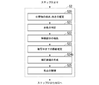
- step S2 in FIG. 2 the operation of the adjusting unit 10 of the biometric authentication device 1 (step S2 in FIG. 2) will be described in detail with reference to FIG.
- the operation of the adjustment unit 10 of the biometric authentication device 1 first, the operation of the adjustment unit 10 when the person of the subject to be biometric authentication is stopped is described, and then the adjustment unit when the person moves. The operation of 10 will be described.
- the focusing determination unit 102 analyzes the image information output from the image information acquisition unit 101, and performs focusing determination, which is a determination of whether or not the subject is in focus (step S21).
- focusing determination a focusing index indicating whether or not the image is in focus in a predetermined area is calculated.
- the in-focus index is an index that becomes higher as the image is in focus, and is, for example, a value that evaluates the power of a high-frequency component of an image and the amount of an edge component. There are various methods for determining whether or not the subject is in focus using the focus index.
- the focus control is used to take a picture while shifting the focus position, obtain the focus index, and determine the maximum point. You may ask for it and make a focus determination. In the latter case, it is not immediately possible to know whether or not the image is in focus on the spot, and after taking a picture by moving the focus position several times, the image in focus is known. Therefore, it is necessary for the image selection unit 107, which will be described later, to temporarily hold an image that may be selected as an in-focus image.
- Focusing information is information indicating whether or not the target image is in focus. This may be binary information indicating whether it is in focus or not, or it may be a continuous value indicating the degree of focus. When it is a continuous value, for example, the above-mentioned focusing score value may be used as it is.
- an index that identifies the image with the maximum focusing index while the focus is shaken. Include (frame numbers, timestamps, etc.).
- This focusing information is information indicating the degree of focusing. The obtained focusing information is input to the correction unit 105. Further, the information indicating which frame is in focus or the information indicating the degree of focusing is output to the image selection unit 107 as selection information.
- the feature point extraction unit 103 performs face detection or head detection on the input image, and obtains a face landmark which is a position of a characteristic portion included in the face or the head (step S22).
- the face landmark may also be simply referred to as a landmark or a feature point.
- the face or head itself or its part can be detected by using a detector that has learned the feature points of the face or head or its part.
- a detector is used that extracts Histograms of Oriented Gradients (HOG) features, which is one of the features extraction methods from images, and detects them based on the extracted features.
- HOG Histograms of Oriented Gradients
- a detector that directly detects from an image using CNN (Convolutional Neural Network), which is a kind of image recognition by machine learning, may be used.
- the feature point extraction unit 103 may obtain the position information (position coordinates on the image) of only the feature points used for estimating the distance to the subject in the distance estimation unit 104.
- the position information position coordinates on the image
- the pupils of both eyes are set as feature points and the positions thereof are obtained.
- the position of the pupil instead of the position of the pupil, the position of other feature points of the eye (inner eye angle, outer eye angle, etc.) may be obtained, and the distance between these feature points may be used instead of the inter-eye distance.
- the distance to other feature points such as the nose and mouth may be used instead of the eyes, and in that case, the position of the feature point to be used may be obtained.
- the obtained landmark position information is output to the distance estimation unit 104.
- the distance estimation unit 104 estimates the distance to the subject from the obtained landmark position information (step S23). Assuming that the individual difference in the size of the human face is not large, the distance from the subject to the face can be roughly estimated from the distance between the positions of the feature points. As described above, various feature points can be used, but in the following, as an example, the pupils of both eyes are used as feature points, and the distance to the subject is used using the interpupillary distance, which is the distance between the pupils. The case of obtaining is described.
- the distance estimation unit 104 may obtain a relational expression between the eye-to-eye distance and the distance from the camera to the subject in advance, and obtain the distance to the subject based on the formula. That is, if the distance between the eyes is d and the estimated distance to the subject is D E , the relational expression can be expressed as Equation 1.
- This function f (d) is obtained in advance and used.
- the function f (d) may be approximated by a straight line obtained by linear regression, or it may be obtained by applying a polynomial or other mathematical formula. Alternatively, it may be expressed by combining those approximated for each section.
- the estimated distance to the subject obtained in this way is output to the correction unit 105 as estimated distance information.
- the correction unit 105 generates information on the correction distance for correcting the distance to the subject based on the estimated distance information and the focusing information (step S24). The processing of the correction unit 105 will be described in detail separately.
- the focus control unit 106 generates control information for controlling the focus of the image pickup apparatus 2 based on the correction distance information (step S25). As described above, this control information is generated according to the method of focusing by the image pickup apparatus 2. Further, the focus control unit 106 outputs the generated control information to the image information acquisition unit 101. The image information acquisition unit 101 controls the focus of the image pickup apparatus 2 using the obtained control information, and obtains a new image having a different focus from the image for which the focus is controlled.
- the correction unit 105 generates information on the correction distance for correcting the distance to the subject based on the estimated distance information and the focusing information.
- the correction unit 105 may use the estimated distance input in the past and the corresponding correction distance and focusing information instead of the estimated distance and focusing information at the current time. Therefore, it is assumed that the correction unit 105 holds the results of the estimated distance input and the output correction distance within a certain period of time in association with the time.
- the method of correcting the distance based on the estimated distance D E and obtaining the corrected distance D C is arbitrary. In the following, a case where the correction distance D C is obtained by adding the difference distance ⁇ D to the estimated distance D E will be described.
- the correction method is not limited to the method described below.
- the operation of the correction unit 105 is roughly classified into a focusing distance search mode and a focusing tracking mode.
- Focusing distance search mode is a mode for obtaining the focusing differential distance [Delta] D f in a state of focusing the difference metric [Delta] D f corresponds to the in-focus state has not been obtained.
- the focusing tracking mode is a mode in which after the focusing difference distance ⁇ D f is obtained, the distance is corrected using the value and the focusing state is maintained.
- the operation of the correction unit 105 in each mode will be described.
- the focusing difference distance ⁇ D f is indefinite, so the camera operates in the focusing distance search mode.
- the correction distance D C is calculated from the estimated distance D E according to a certain rule.
- the variation from the initial estimated distance estimate the variation from the initial estimated distance (estimated distance at time t 0)
- the correction distance Dc can be expressed as Equation 2.
- g 1 represents the variation obtained in the focusing distance search mode.
- n indicates the number of times the processing shown in FIG. 3 was performed from the time t 0 at which the initial estimated distance was obtained
- t n indicates the time at the nth time.
- N 1 is a value that determines the average number of continuations until the input focusing information indicates that the focus has been achieved in the focusing distance search mode as an index.
- the value is smaller than the average number of continuations of the number of repetitions until the focusing information indicates that the focus is in focus, for example, a value approximately half of the average number of continuations.
- the estimated distance D E at time t j (t j) is changed more than a certain percentage from the initial estimated distance D E (t 0) is the estimated distance D E at time t j a (t j) You may try the search again based on the reference.
- the difference distance ⁇ D at that time is obtained as the focusing difference distance ⁇ D f .
- the difference between the correction distance and the estimated distance at time t i is the individual. It means that the distance is different based on the difference. Therefore, the value obtained by subtracting the estimated distance from the correction distance shown in Equation 4 is obtained as the focusing difference distance ⁇ D f , and is stored as the difference distance information for the target person.
- the above focusing difference distance may depend on the estimated distance D E. Therefore, as shown in Equation 6, the focusing difference distance ⁇ D f is regarded as a function of the estimated distance D E , and each time the focus is reached, the set of the difference distance and the estimated distance at the time of focusing is accumulated and this function is obtained. You may do so.
- the difference distance information is information that describes a function for obtaining the focusing difference distance ⁇ D f from the estimated distance D E.
- the distance is controlled to be constant regardless of the estimated distance D E , and if the focus is lost when the D E changes, the focus position is adjusted by slightly shaking the focus position as described later, and the focus difference is adjusted. Find the distance. This is associated with D E and stored and used. At this time, fitting by a regression line may be performed and the coefficient may be held as the difference distance information.
- the focusing information obtained as a result of controlling by the correction distance obtained in this way indicates that the focus is not sufficiently focused, the distance is further changed slightly before and after that. For example, it is conceivable to control according to Equation 7 using a function g 2 (t) whose range is narrower than g 1 (t).
- g 2 represents the fluctuation amount obtained in the focusing tracking mode.
- g 2 (t) for example, 0 ⁇
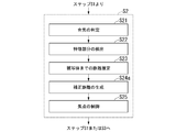
- FIG. 4 is a flowchart showing the processing flow of the correction unit 105.
- the correction unit 105 checks whether or not there is difference distance information (whether or not it has already been calculated) (step S24a). When the difference distance information has not been obtained yet (step S24a: No), the correction unit 105 calculates the focus difference distance in the focus distance search mode (step S24b). When the difference distance information has already been obtained (step S24a: Yes), the correction unit 105 adjusts the focus difference distance in the focus tracking mode (step S24c). Then, the correction unit 105 calculates the correction distance from the obtained focusing difference distance (step S24d).
- the above process is repeated until an image focused to the extent that sufficient accuracy can be obtained in biometric authentication is obtained, or a predetermined number of times.
- the correction distance information obtained in this way is output to the focus control unit 106.
- biometric authentication device 1 when the subject is not stationary at a fixed place but the subject moves.
- biometric authentication is performed by changing the position of the focal point according to the movement of a person.
- a person performs authentication while moving toward the image pickup apparatus 2 will be described. It should be noted that the application is not limited to the case where the person moves toward the image pickup apparatus 2, and the same applies to any case where the movement of the person can be predicted.
- the distance to the subject decreases with the passage of time. Therefore, if the focus is set to a distance shorter than the current subject distance, the subject distance becomes the set distance at a slightly later point, and the in-focus image can be acquired. Then, after the in-focus image is acquired, the focus is set so that the in-focus image can be acquired in a little later time at the subject distance assumed at a little later time. That is, the correction distance is calculated so that the in-focus image can be acquired in the previous time.
- the walking speed of the person or the time when the next new image is acquired so that the in-focus image can be acquired at the time before the next image is acquired.
- the correction distance is calculated by using the information that is the basis of the prediction for acquiring the in-focus image, such as the predicted movement distance of the person. Then, after acquiring the in-focus image, the same procedure is repeated. This makes it possible to acquire in-focus images at a plurality of positions and perform biometric authentication.
- the operation of the correction unit 105 that realizes this will be described.
- the correction distance D C (t n ) is calculated by the number tens, where L is a value slightly larger than the maximum value of
- This fixed value is output as a correction value until it indicates that the focusing information is in focus.
- the focusing information is in focus, it is obtained as the focusing difference distance ⁇ D f by the equation 4 in the same manner as described above.
- the in-focus tracking mode In the in-focus tracking mode, the subject distance at a point slightly ahead is predicted, and the correction distance D C is set so that the subject is in focus at that point. If the time of the focused image is t i , then the elapsed time from the time t i of the scheduled time to acquire the in-focus image (this is t m ) is calculated, and the distance that can be moved during that time is calculated. Find and find a distance slightly larger than that distance as L M. Then, the correction distance D C is calculated by the equation 11.
- L M is represented by the equation 12.
- the walking speed V of the person an average value may be used, or the walking speed V may be estimated and used from the time variation of the inter-eye distance d. That is, the walking speed V may be estimated and used by using the calculation history of the estimated distance D E at a time earlier than this.
- the correction distance D C obtained in this way is output until the subject distance becomes this value and the focusing information by the focusing determination unit 102 indicates that the subject is in focus.
- L M is calculated again in the same manner as described above, and the correction distance Dc is calculated.
- the focusing difference distance ⁇ D f may also be calculated and updated.
- the value obtained at a close position is generally more accurate than the focusing difference distance obtained at a position where the subject is far, because the accuracy of the relative position between the face landmarks is improved. Therefore, by appropriately updating the focusing difference distance ⁇ D f, the estimation accuracy of the focusing position can be improved, the number of times biometric authentication can be performed increases, and the failure rate of biometric authentication can be reduced.
- the operations other than the correction unit 105 are the same as when the person is stopped.
- the search in the focusing distance search mode by the correction unit 105 can be executed even before the person approaches a distance suitable for biometric authentication.
- the mode shifts to the focusing tracking mode, so that faster authentication becomes possible.
- Biometrics can be performed faster. Therefore, even if the acquisition of the biometric image fails once, it can be recovered by the subsequent image acquisition, and the biometric authentication can be performed more reliably.
- FIG. 5 shows a functional block diagram of the biometric authentication device 1 according to the second embodiment.
- the difference from the functional block diagram of the biometric authentication device 1 in the second embodiment shown in FIG. 1 is in the correction unit 105a, and the other processing units are the same.
- the correction unit 105a of the biometric authentication device 1 in the second embodiment receives the input of the difference distance information
- the correction unit 105a corrects the estimated distance based on the input difference distance information and generates the correction distance.
- FIG. 6 shows the operation of the adjusting unit 10a of the biometric authentication device 1 in the second embodiment.
- the difference in operation of the biometric authentication device 1 from the adjusting unit 10 in the first embodiment is the operation of the correction unit 105a in step S24a.
- the operation of the correction unit 105a in step S24a will be described.
- the operation of the correction unit 105a receives input of the difference distance information from the portable medium 3 and generates the correction distance using the input difference distance information, as compared with the operation of the correction unit 105 in the first embodiment.
- the difference distance information is basically the same as the difference distance information described in the first embodiment, and is information for correcting individual differences.
- the difference distance information obtained at the time of the previous authentication is stored in the portable medium 3 such as a smartphone, and is read and input by the system at the time of the next authentication.
- the correction unit 105a when registering biometric authentication, if the difference distance information is obtained by the same procedure as at the time of collation, the correction unit 105a stores the difference distance information obtained at that time and uses it at the time of collation. It may be. Further, instead of storing the difference distance information itself, the distance between the eyes and the like is measured or estimated together at the time of registration and stored in the portable medium 3, and then the difference distance information is obtained. May be good.
- the correction unit 105a calculates the correction distance based on the value. That is, the correction distance is calculated according to Equation 5 from the beginning. As a result, it becomes possible to focus faster than when the difference distance information is not known, and the time required for biometric authentication can be shortened.
- FIG. 7 shows a functional block diagram of the biometric authentication device 1 according to the third embodiment.
- the difference from the functional block diagram of the biometric authentication device 1 in the first embodiment shown in FIG. 1 is in the image analysis unit 109 and the correction unit 105b, and the other processing units are the same.
- the image analysis unit 109 in the third embodiment at least either generates incidental information by detecting an accessory of the face in the subject or calculates information on the orientation of the face. Do one or the other.
- the correction unit 105b changes the method of calculating the correction distance based on one or both of the incidental information or the face orientation information obtained by the image analysis unit 109.
- FIG. 8 shows the operation of the adjusting unit 10b of the biometric authentication device 1 in the third embodiment.
- the difference in operation of the biometric authentication device 1 from the adjusting unit 10 in the first embodiment is the operation of the image analysis unit 109 in step S20 and the correction unit 105b in step S24b.
- the operations of the image analysis unit 109 and the correction unit 105b will be described.
- the image analysis unit 109 detects an accessory attached to the face from the image output from the image information acquisition unit 101, estimates the face orientation, and obtains the obtained accessory and orientation information (step). S20).
- the image analysis unit 109 detects whether or not there is an accessory on the face with respect to the input image.
- the accessory refers to an object attached to the face, and specifically, glasses, sunglasses, an eye patch, goggles, a mask, a nicab, and the like. This detection can be detected by using a detector learned in the same manner as general object detection.
- the image analysis unit 109 also calculates the orientation of the face. That is, it is calculated how much the direction is deviated from the front direction in the vertical direction and the horizontal direction. This can also be determined using a determination device trained for each face orientation.
- the obtained incidental information and face orientation information are output to the correction unit 105b.
- the correction unit 105b includes the estimated distance information output from the distance estimation unit 104, the focusing information output from the focusing determination unit 102, the incidental information output from the image analysis unit 109, and the face orientation information. Then, the correction distance is obtained and output to the focus control unit 106 (step S24b).
- the correction unit 105b adjusts the distance correction method based on the incidental / orientation information.
- the correction is performed in the same manner as in the correction unit 105.
- the correction unit 105b changes the correction method accordingly if there is an accessory.
- the measured inter-eye distance may deviate from the correct value due to the refraction of the spectacle lens. Therefore, this deviation is also taken into consideration when correcting.
- the correction unit 105b may control the range of the correction distance to be changed in the focusing distance search mode so as to be biased toward the closer side. good.
- the distance between the eyes may be corrected in consideration of the direction.
- the correction unit 105b adds the correction amount due to the inclination to the difference distance to perform the correction.
- the corrected inter-eye distance d'shown in Equation 13 is used instead of the inter-eye distance d.
- the correction unit 105b may be capable of inputting the difference distance as in the correction unit 105a described in the second embodiment. In this case, the correction unit 105b generates the correction distance using the input difference distance information. In this way, even when an accessory is attached to the face or the orientation is not the front, the focus can be achieved at high speed by performing the correction in consideration of the fact.
- FIG. 9 shows a functional block diagram of the biometric authentication device 1 according to the fourth embodiment.
- the difference from the functional block diagram of the biometric authentication device 1 in the third embodiment shown in FIG. 7 is that there is a focusing determination unit 102c, and the other processing units are the same.
- the focusing determination unit 102c in the fourth embodiment changes the selection criteria of the image for biometric authentication from the image of the subject based on the information on the incidental objects or the orientation information of the face obtained by the image analysis unit 109.
- FIG. 10 shows the operation of the adjusting unit 10c of the biometric authentication device 1 in the fourth embodiment.
- the difference in operation of the biometric authentication device 1 from the adjusting unit 10b in the third embodiment is the operation of the focusing determination unit 102c in step S21c.
- the operations of the image analysis unit 109 and the focus determination unit 102c will be described.
- the image analysis unit 109 detects ancillary objects attached to the face from the image output from the image information acquisition unit 101, estimates the face orientation, and provides information on the obtained ancillary objects and information on the face orientation. (Step S20). The details of the operation of the image analysis unit 109 are as described in the third embodiment.
- the focusing determination unit 102c generates focusing information and selection information based on the image output from the image information acquisition unit 101, information on incidental objects output from the image analysis unit 109, and face orientation information. Focusing information is output to the correction unit 105b, and selection information is output to the image selection unit 107 (step S21c). That is, when the focusing determination unit 102c indicates that there is no accessory on the face and the orientation of the face is front from the information on the incidental objects and the information on the orientation of the face, the operation of the focusing determination unit 102c is Performs the same operation as. On the other hand, when indicating that there is an accessory such as eyeglasses, the focusing determination unit 102c may change the focusing determination method or the selection information determination method.
- the biometric authentication is iris authentication
- the frame of the spectacles may be in focus and the iris may not be in focus. Therefore, when the accessory information includes spectacles, a position shifted slightly far from the position where the focusing score is maximized may be obtained as the focusing position.
- the selection information not only the frame having the maximum focusing index but also the frame at a position slightly farther from the focal position may be selected. By doing so, it is possible to reduce the risk that the acquired image is out of focus to the part required for biometric authentication, and it is possible to reduce the failure rate of biometric authentication when there are incidentals.
- face authentication that is, iris authentication, etc.
- iris authentication has been described as an example of biometric authentication, but the present invention is not limited to this. It can be applied as long as it is a method of authenticating using image information of a living body other than the face, and for example, it can be applied to non-contact fingerprint / palm print and vein authentication. In this case, the landmark information becomes the feature points of the palm and fingers.
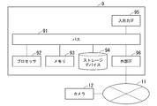
- FIG. 11 is a diagram illustrating a hardware configuration of the biometric authentication device.
- the network 11 and the camera 12 are illustrated.
- the computer 9 is an arbitrary computer.
- the computer 9 is a personal computer (PC), a server machine, a tablet terminal, a smartphone, or the like.
- the computer 9 may be a dedicated computer designed to realize the biometric authentication device 1, or may be a general-purpose computer.
- the computer 9 includes a bus 91, a processor 92, a memory 93, a storage device 94, an input / output interface 95, and an external interface 96.
- the bus 91 is a data transmission path for the processor 92, the memory 93, the storage device 94, the input / output interface 95, and the external interface 96 which also serves as a network interface to transmit and receive data to and from each other.
- the method of connecting the processors 92 and the like to each other is not limited to the bus connection.
- the processor 92 is various processors such as a CPU (Central Processing Unit), a GPU (Graphics Processing Unit), or an FPGA (Field-Programmable Gate Array).
- the memory 93 is a main storage device realized by using RAM (Random Access Memory) or the like.
- the storage device 94 is an auxiliary storage device realized by using a hard disk, an SSD (Solid State Drive), a memory card, a ROM (Read Only Memory), or the like.
- the input / output interface 95 is an interface for connecting the computer 9 and the input / output device.
- an input device such as a keyboard and an output device such as a display device are connected to the input / output interface 95.
- the external interface 96 is an interface for connecting the computer 9 to the network 11 or the like.
- FIG. 11 shows a case where the external interface 96 is a network interface and is connected to the network 11, but the present invention is not limited to this.
- this network is, for example, LAN (Local Area Network) or WAN (Wide Area Network).
- the method of connecting the external interface 96 to the network may be a wireless connection or a wired connection.
- the external interface 96 may be an interface for directly connecting an external device instead of a network interface.
- it may be directly connected to the camera 12 without going through a network by USB (Universal Serial Bus), IEEE1394, or the like.
- a camera 12 is connected to the network 11, and the computer 9 and the camera 12 can communicate data via the network 11.
- the camera 12 corresponds to the image pickup device 2 of the biometric authentication device 1.
- the storage device 94 stores a program module that realizes each processing unit of the biometric authentication device 1.
- the processor 92 realizes the function corresponding to each program module by reading each of these program modules into the memory 93 and executing the module. Note that some functions of the biometric authentication device 1 may be executed on the camera 12 side. That is, even if a processor, a storage device, and a memory are stored inside the camera 12, all or part of the processing of each processing unit of the biometric authentication device 1 is executed by using these components. good.
- the image information acquisition unit 101, the focusing determination unit 102, the feature point extraction unit 103, the distance estimation unit 104, the correction unit 105 (105a), the focus control unit 106, the image selection unit 107, and the biometric authentication unit 108 are on the camera 12 side.
- other processing may be executed on the computer 9 side.
- the processing of the feature point extraction unit 103 may also be executed on the camera 12 side, and other processing may be executed on the computer 9 side.
- all the processes other than the biometric authentication unit 108 may be executed on the camera side.
- FIG. 12 is a diagram showing a minimum configuration diagram of the biometric authentication device 1.
- the biometric authentication device 1 includes a correction unit 105, a focus control unit 106, and a focus determination unit 102.
- FIG. 13 is a diagram showing a processing flow diagram of the biometric authentication device in the minimum configuration shown in FIG.
- the correction unit 105 is a difference distance information obtained based on the focusing information indicating the degree of focusing in the image of the subject to be bioauthenticated and the estimated distance to the subject obtained from the distance between the feature points of the image.
- the correction that corrects the deviation between the estimated distance and the focusing distance with respect to the subject based on the difference distance information by using the difference distance information indicating the deviation between the estimated distance and the focusing distance with respect to the subject.
- Generate a distance step S101).
- the focus control unit 106 generates information for controlling the focus of the subject at the time of image acquisition based on the correction distance (step S102).
- the focusing determination unit 102 generates information for selecting an image to be biometrically authenticated from the images of the subject taken after controlling the focus (step S103). The above process may be repeated until a focused image capable of performing authentication with a predetermined accuracy in biometric authentication is obtained.
- the biometric authentication device 1 will be able to focus at high speed in consideration of individual differences. Therefore, it is possible to focus at high speed when focusing and shooting from the second time onward, and even if the first image acquisition fails, biometric authentication can be performed at high speed.
- biometric authentication device 1 does not require an additional device, and has an effect that the image quality can be improved, which leads to improvement in the accuracy of biometric authentication.
- the biometric authentication device 1 it becomes possible to focus at high speed and execute biometric authentication without a sensor for measuring the distance to the subject to be biometric authentication. Further, it can be used regardless of whether the person to be biometrically authenticated is stationary or moving. Therefore, it can be used for a biometric authentication system for payment, a biometric authentication system for a gate while walking, and the like.
- Biometric authentication device 2 Imaging device 3 Portable medium 10, 10a, 10b, 10c Adjustment unit 101 Image information acquisition unit 102, 102c Focus determination unit 103 Feature point extraction unit 104 Distance estimation unit 105, 105a, 105b Correction unit 106 Focus Control unit 107 Image selection unit 108 Biometrics unit 109 Image analysis unit
Landscapes
- Engineering & Computer Science (AREA)
- Theoretical Computer Science (AREA)
- Computer Security & Cryptography (AREA)
- Physics & Mathematics (AREA)
- General Physics & Mathematics (AREA)
- Signal Processing (AREA)
- Multimedia (AREA)
- Computer Hardware Design (AREA)
- Software Systems (AREA)
- General Engineering & Computer Science (AREA)
- Measurement Of The Respiration, Hearing Ability, Form, And Blood Characteristics Of Living Organisms (AREA)
- Collating Specific Patterns (AREA)
- Studio Devices (AREA)
Priority Applications (5)
| Application Number | Priority Date | Filing Date | Title |
|---|---|---|---|
| EP20919661.7A EP4109876A4 (en) | 2020-02-21 | 2020-02-21 | BIOMETRIC AUTHENTICATION DEVICE, BIOMETRIC AUTHENTICATION METHOD AND BIOMETRIC AUTHENTICATION PROGRAM |
| JP2022501556A JP7302729B2 (ja) | 2020-02-21 | 2020-02-21 | 生体認証装置、生体認証方法、および生体認証用プログラム |
| PCT/JP2020/007076 WO2021166223A1 (ja) | 2020-02-21 | 2020-02-21 | 生体認証装置、生体認証方法、および生体認証用プログラム |
| US17/799,976 US12339941B2 (en) | 2020-02-21 | 2020-02-21 | Biometric authentication device, biometric authentication method, and biometricauthentication program |
| JP2023100888A JP7439980B2 (ja) | 2020-02-21 | 2023-06-20 | 生体認証装置、生体認証方法、および生体認証用プログラム |
Applications Claiming Priority (1)
| Application Number | Priority Date | Filing Date | Title |
|---|---|---|---|
| PCT/JP2020/007076 WO2021166223A1 (ja) | 2020-02-21 | 2020-02-21 | 生体認証装置、生体認証方法、および生体認証用プログラム |
Publications (1)
| Publication Number | Publication Date |
|---|---|
| WO2021166223A1 true WO2021166223A1 (ja) | 2021-08-26 |
Family
ID=77390743
Family Applications (1)
| Application Number | Title | Priority Date | Filing Date |
|---|---|---|---|
| PCT/JP2020/007076 Ceased WO2021166223A1 (ja) | 2020-02-21 | 2020-02-21 | 生体認証装置、生体認証方法、および生体認証用プログラム |
Country Status (4)
| Country | Link |
|---|---|
| US (1) | US12339941B2 (https=) |
| EP (1) | EP4109876A4 (https=) |
| JP (2) | JP7302729B2 (https=) |
| WO (1) | WO2021166223A1 (https=) |
Cited By (4)
| Publication number | Priority date | Publication date | Assignee | Title |
|---|---|---|---|---|
| JPWO2023042248A1 (https=) * | 2021-09-14 | 2023-03-23 | ||
| WO2023157056A1 (ja) | 2022-02-15 | 2023-08-24 | 日本電気株式会社 | 情報処理システム、情報処理方法、及び記録媒体 |
| WO2024252924A1 (ja) * | 2023-06-08 | 2024-12-12 | 日本電気株式会社 | 情報処理装置、情報処理システム、情報処理方法及びプログラム |
| WO2025187045A1 (ja) * | 2024-03-08 | 2025-09-12 | 日本電気株式会社 | 情報処理システム、情報処理装置、情報処理方法及び記録媒体 |
Citations (5)
| Publication number | Priority date | Publication date | Assignee | Title |
|---|---|---|---|---|
| JP2004226729A (ja) * | 2003-01-23 | 2004-08-12 | Matsushita Electric Ind Co Ltd | 認証対象画像撮像装置 |
| JP2006221422A (ja) | 2005-02-10 | 2006-08-24 | Fuji Electric Device Technology Co Ltd | 人物認証装置 |
| JP2007094535A (ja) | 2005-09-27 | 2007-04-12 | Konica Minolta Photo Imaging Inc | 認証システム及び認証方法 |
| JP2007159762A (ja) * | 2005-12-13 | 2007-06-28 | Matsushita Electric Ind Co Ltd | 生体認証装置用距離測定装置および生体認証装置 |
| JP2019168479A (ja) | 2018-03-22 | 2019-10-03 | キヤノン株式会社 | 制御装置、撮像装置、制御方法、プログラム、および、記憶媒体 |
Family Cites Families (7)
| Publication number | Priority date | Publication date | Assignee | Title |
|---|---|---|---|---|
| JP2006338236A (ja) * | 2005-06-01 | 2006-12-14 | Matsushita Electric Ind Co Ltd | 眼画像撮影装置およびそれを用いた認証装置 |
| US8213782B2 (en) | 2008-08-07 | 2012-07-03 | Honeywell International Inc. | Predictive autofocusing system |
| JP5808124B2 (ja) * | 2011-03-24 | 2015-11-10 | キヤノン株式会社 | 焦点検出装置及びその制御方法並びに焦点検出装置を有する撮像装置 |
| US9794467B2 (en) * | 2013-11-01 | 2017-10-17 | Canon Kabushiki Kaisha | Focus adjustment apparatus, method for controlling focus adjustment apparatus, and storage medium |
| JP6327161B2 (ja) | 2015-01-23 | 2018-05-23 | 株式会社デンソー | 後写鏡制御装置 |
| US10579871B2 (en) * | 2016-02-03 | 2020-03-03 | Hefei Xu | Biometric composite imaging system and method reusable with visible light |
| WO2018220963A1 (ja) | 2017-06-02 | 2018-12-06 | ソニー株式会社 | 情報処理装置、情報処理方法、及びプログラム |
-
2020
- 2020-02-21 WO PCT/JP2020/007076 patent/WO2021166223A1/ja not_active Ceased
- 2020-02-21 EP EP20919661.7A patent/EP4109876A4/en not_active Withdrawn
- 2020-02-21 US US17/799,976 patent/US12339941B2/en active Active
- 2020-02-21 JP JP2022501556A patent/JP7302729B2/ja active Active
-
2023
- 2023-06-20 JP JP2023100888A patent/JP7439980B2/ja active Active
Patent Citations (5)
| Publication number | Priority date | Publication date | Assignee | Title |
|---|---|---|---|---|
| JP2004226729A (ja) * | 2003-01-23 | 2004-08-12 | Matsushita Electric Ind Co Ltd | 認証対象画像撮像装置 |
| JP2006221422A (ja) | 2005-02-10 | 2006-08-24 | Fuji Electric Device Technology Co Ltd | 人物認証装置 |
| JP2007094535A (ja) | 2005-09-27 | 2007-04-12 | Konica Minolta Photo Imaging Inc | 認証システム及び認証方法 |
| JP2007159762A (ja) * | 2005-12-13 | 2007-06-28 | Matsushita Electric Ind Co Ltd | 生体認証装置用距離測定装置および生体認証装置 |
| JP2019168479A (ja) | 2018-03-22 | 2019-10-03 | キヤノン株式会社 | 制御装置、撮像装置、制御方法、プログラム、および、記憶媒体 |
Cited By (8)
| Publication number | Priority date | Publication date | Assignee | Title |
|---|---|---|---|---|
| JPWO2023042248A1 (https=) * | 2021-09-14 | 2023-03-23 | ||
| WO2023042248A1 (ja) * | 2021-09-14 | 2023-03-23 | 日本電気株式会社 | 情報処理システム、情報処理装置、情報処理方法、及び記録媒体 |
| EP4403974A4 (en) * | 2021-09-14 | 2024-10-16 | NEC Corporation | INFORMATION PROCESSING SYSTEM, INFORMATION PROCESSING DEVICE, INFORMATION PROCESSING METHOD, AND RECORDING MEDIUM |
| US12236714B2 (en) * | 2021-09-14 | 2025-02-25 | Nec Corporation | Information processing system, information processing apparatus, information processing method, and recording medium |
| JP7715197B2 (ja) | 2021-09-14 | 2025-07-30 | 日本電気株式会社 | 情報処理システム、情報処理装置、情報処理方法、及び記録媒体 |
| WO2023157056A1 (ja) | 2022-02-15 | 2023-08-24 | 日本電気株式会社 | 情報処理システム、情報処理方法、及び記録媒体 |
| WO2024252924A1 (ja) * | 2023-06-08 | 2024-12-12 | 日本電気株式会社 | 情報処理装置、情報処理システム、情報処理方法及びプログラム |
| WO2025187045A1 (ja) * | 2024-03-08 | 2025-09-12 | 日本電気株式会社 | 情報処理システム、情報処理装置、情報処理方法及び記録媒体 |
Also Published As
| Publication number | Publication date |
|---|---|
| JP7302729B2 (ja) | 2023-07-04 |
| US20230083281A1 (en) | 2023-03-16 |
| JP2023126236A (ja) | 2023-09-07 |
| EP4109876A1 (en) | 2022-12-28 |
| JPWO2021166223A1 (https=) | 2021-08-26 |
| US12339941B2 (en) | 2025-06-24 |
| EP4109876A4 (en) | 2023-02-08 |
| JP7439980B2 (ja) | 2024-02-28 |
Similar Documents
| Publication | Publication Date | Title |
|---|---|---|
| JP7439980B2 (ja) | 生体認証装置、生体認証方法、および生体認証用プログラム | |
| AU2016264503B2 (en) | Tilt shift iris imaging | |
| KR102078249B1 (ko) | 얼굴 인증 방법, 얼굴 인증 장치, 이를 위한 컴퓨터 프로그램 | |
| JP5766564B2 (ja) | 顔認証装置及び顔認証方法 | |
| JP4156430B2 (ja) | データベース自動更新方法を用いた顔検証方法及びそのシステム | |
| US9684850B2 (en) | Biological information processor | |
| JP4811259B2 (ja) | 視線方向推定装置及び視線方向推定方法 | |
| CN110781712B (zh) | 一种基于人脸检测与识别的人头空间定位方法 | |
| US10430644B2 (en) | Blended iris and facial biometric system | |
| CN114270417A (zh) | 能够更新注册人脸模板的人脸识别系统及方法 | |
| JP7156511B2 (ja) | 物体検出装置、物体検出システム、物体検出方法及びプログラム | |
| WO2024010780A1 (en) | Image capture devices, systems, and methods | |
| WO2006035890A1 (ja) | 視線検出方法 | |
| JP5971712B2 (ja) | 監視装置及び方法 | |
| JP6572841B2 (ja) | 情報処理装置及びプログラム | |
| JP2004192552A (ja) | 開閉眼判定装置 | |
| CN109770845A (zh) | 测量瞳距的装置和方法 | |
| KR101066097B1 (ko) | 안경 착용자에 대한 오인식을 최소화한 얼굴 인식 장치 및 이를 이용한 안경 착용자에 대한 얼굴 오인식 최소화 방법 | |
| US20250380051A1 (en) | Information processing apparatus, information processing system, information processing method, and non-transitory computer readable medium | |
| KR20150135745A (ko) | 얼굴 인식 장치 및 방법 | |
| EP4465247A1 (en) | Method and system for predicting distance of gazed objects using infrared (ir) camera | |
| JP7103443B2 (ja) | 情報処理装置、情報処理方法、およびプログラム | |
| JP2012212325A (ja) | 視線計測システム、方法およびプログラム | |
| Middendorff et al. | Multibiometrics using face and ear | |
| WO2024247251A1 (ja) | 情報処理システム、情報処理装置、情報処理方法、記憶媒体 |
Legal Events
| Date | Code | Title | Description |
|---|---|---|---|
| 121 | Ep: the epo has been informed by wipo that ep was designated in this application |
Ref document number: 20919661 Country of ref document: EP Kind code of ref document: A1 |
|
| ENP | Entry into the national phase |
Ref document number: 2022501556 Country of ref document: JP Kind code of ref document: A |
|
| NENP | Non-entry into the national phase |
Ref country code: DE |
|
| ENP | Entry into the national phase |
Ref document number: 2020919661 Country of ref document: EP Effective date: 20220921 |
|
| WWG | Wipo information: grant in national office |
Ref document number: 17799976 Country of ref document: US |