WO2021166223A1 - 生体認証装置、生体認証方法、および生体認証用プログラム - Google Patents
生体認証装置、生体認証方法、および生体認証用プログラム Download PDFInfo
- Publication number
- WO2021166223A1 WO2021166223A1 PCT/JP2020/007076 JP2020007076W WO2021166223A1 WO 2021166223 A1 WO2021166223 A1 WO 2021166223A1 JP 2020007076 W JP2020007076 W JP 2020007076W WO 2021166223 A1 WO2021166223 A1 WO 2021166223A1
- Authority
- WO
- WIPO (PCT)
- Prior art keywords
- distance
- information
- image
- subject
- correction
- Prior art date
Links
Images


Classifications
-
- H—ELECTRICITY
- H04—ELECTRIC COMMUNICATION TECHNIQUE
- H04N—PICTORIAL COMMUNICATION, e.g. TELEVISION
- H04N23/00—Cameras or camera modules comprising electronic image sensors; Control thereof
- H04N23/60—Control of cameras or camera modules
- H04N23/61—Control of cameras or camera modules based on recognised objects
- H04N23/611—Control of cameras or camera modules based on recognised objects where the recognised objects include parts of the human body
-
- G—PHYSICS
- G06—COMPUTING; CALCULATING OR COUNTING
- G06F—ELECTRIC DIGITAL DATA PROCESSING
- G06F21/00—Security arrangements for protecting computers, components thereof, programs or data against unauthorised activity
- G06F21/30—Authentication, i.e. establishing the identity or authorisation of security principals
- G06F21/31—User authentication
- G06F21/32—User authentication using biometric data, e.g. fingerprints, iris scans or voiceprints
-
- G—PHYSICS
- G06—COMPUTING; CALCULATING OR COUNTING
- G06T—IMAGE DATA PROCESSING OR GENERATION, IN GENERAL
- G06T1/00—General purpose image data processing
-
- H—ELECTRICITY
- H04—ELECTRIC COMMUNICATION TECHNIQUE
- H04N—PICTORIAL COMMUNICATION, e.g. TELEVISION
- H04N23/00—Cameras or camera modules comprising electronic image sensors; Control thereof
- H04N23/60—Control of cameras or camera modules
-
- H—ELECTRICITY
- H04—ELECTRIC COMMUNICATION TECHNIQUE
- H04N—PICTORIAL COMMUNICATION, e.g. TELEVISION
- H04N23/00—Cameras or camera modules comprising electronic image sensors; Control thereof
- H04N23/60—Control of cameras or camera modules
- H04N23/67—Focus control based on electronic image sensor signals
- H04N23/675—Focus control based on electronic image sensor signals comprising setting of focusing regions
Definitions
- the present invention relates to a biometric authentication device, a biometric authentication method, and a biometric authentication program.
- Patent Document 1 describes an authentication method using the distance from the sensor to each feature point such as the forehead of the face and the tip of the nose.
- Patent Document 2 discloses an authentication system that adjusts an image pickup apparatus using a distance sensor.
- Patent Document 3 even in a state where image deviation occurs due to displacement or deformation of the optical system by obtaining distance information corrected for errors such as parallax amount calculated from two images obtained from the main imaging unit and the sub-imaging unit.
- a control device capable of high-precision and high-speed focus control is disclosed.
- This disclosure is intended to provide a biometric device, a biometric authentication method, and a biometric authentication program that improve the above related techniques.
- the biometric authentication device includes focusing information indicating the degree of focusing in an image of a subject subject to biometric authentication and an estimated distance to the subject obtained from a distance between feature points of the image.
- the difference distance information obtained based on the above, wherein the difference between the estimated distance and the focusing distance with respect to the subject is calculated by using the difference distance information indicating the deviation between the estimated distance and the focusing distance with respect to the subject.
- a correction means for generating a corrected correction distance based on the distance information, a focus control means for generating information for controlling the focus of the subject at the time of image acquisition based on the correction distance, and the focus control are performed. It is provided with a focusing determination means for generating information for selecting an image for biometric authentication from the images of the subject taken after the process.
- the computer-based biometric authentication method estimates the subject from the in-focus information indicating the degree of focusing in the image of the subject to be bioauthenticated and the distance between the feature points of the image. It is the difference distance information obtained based on the distance, and the difference between the estimated distance and the focusing distance with respect to the subject is determined by using the difference distance information indicating the deviation between the estimated distance and the focusing distance with respect to the subject.
- the corrected distance was generated based on the difference distance information, the information for controlling the focus at the time of acquiring the image of the subject was generated based on the corrected distance, and the image was taken after the focus was controlled. Information for selecting an image to be bioauthenticated from the image of the subject is generated.
- the computer is estimated from the focusing information indicating the degree of focusing in the image of the subject to be bioauthenticated and the distance between the feature points of the image to the subject.
- the difference distance information obtained based on the distance, and the deviation of the estimated distance is corrected based on the difference distance information by using the difference distance information indicating the deviation between the estimated distance and the focusing distance with respect to the subject.
- a program that functions as a focusing determination means for generating information for selecting an image for bioauthentication from an image of a subject is recorded.
- FIG. 1 is a diagram showing a configuration of a biometric authentication device 1 according to the first embodiment.
- reference numeral 1 indicates a biometric authentication device
- reference numeral 2 indicates an imaging device.
- the biometric authentication device 1 acquires an image from an image taken by the image pickup device 2 and performs biometric authentication using the obtained image.
- the imaging device 2 is a device capable of imaging a subject including a biological portion subject to biometric authentication.
- the image pickup device 2 is shown in FIG. 1 as a device different from the biometric authentication device 1, the image pickup device 2 may be a part of the biometric authentication device 1.
- the biometric authentication device 1 includes an image information acquisition unit 101, an adjustment unit 10, an image selection unit 107, and a biometric authentication unit 108.
- the image information acquisition unit 101 acquires an image from the image obtained by controlling the image pickup device 2.
- the image information acquisition unit 101 outputs the obtained image information to the adjustment unit 10 and the image selection unit 107. Further, the image information acquisition unit 101 uses the information related to the focus control from the adjustment unit 10 to control the focus of the image pickup apparatus 2 and acquire a new image.
- the adjusting unit 10 determines the degree of focusing in the image obtained by the image information acquisition unit 101, obtains an estimated distance to the subject using the distance between the feature points appearing in the image, and obtains the estimated distance and the subject. Find the difference distance that indicates the deviation of the focusing distance.
- the adjusting unit 10 generates a correction distance obtained by correcting the deviation of the obtained estimated distance based on the difference distance information, and generates information for controlling the focus at the time of image acquisition of the subject based on the correction distance.
- the adjustment unit 10 outputs information for controlling the focus to the image information acquisition unit 101.
- the image selection unit 107 outputs an image for biometric authentication in which the image is in focus to the biometric authentication unit 108 as a selected image.
- the biometric authentication unit 108 performs biometric authentication processing on the selected image output from the image selection unit 107, and generates an authentication result.
- the adjusting unit 10 includes a focusing determination unit 102, a feature point extraction unit 103, a distance estimation unit 104, a correction unit 105, and a focus control unit 106.
- the in-focus determination unit 102 analyzes the image information output from the image information acquisition unit 101 to determine whether or not the image is in focus, and outputs the in-focus information indicating whether or not the image is in focus to the correction unit 105. Further, the focusing determination unit 102 generates selection information which is information for identifying the focused image or frame from the determination result of whether or not the subject is in focus, and outputs the selection information to the image selection unit 107.
- the feature point extraction unit 103 detects a feature point that becomes a face landmark from the image information output from the image information acquisition unit 101, and outputs the position information of the face landmark to the distance estimation unit 104.
- the distance estimation unit 104 estimates the distance from the distance between the landmark positions to the subject based on the landmark position information output from the feature point extraction unit 103, and outputs the estimated distance information to the correction unit 105.
- the correction unit 105 corrects the distance to the subject based on the estimated distance information output from the distance estimation unit 104 and the focusing information output from the focusing determination unit 102, and obtains the corrected distance information.
- the focus control unit 106 generates control information for controlling the focus of the lens based on the correction distance information output from the focus control unit 106, and outputs the control information to the image information acquisition unit 101.
- biometric authentication using all or part of the face and head is targeted.
- face recognition iris recognition
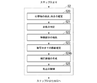
- the image information acquisition unit 101 controls the image pickup device 2 to capture an image of a person as a subject and acquire an image (step S1).
- the image pickup apparatus 2 may be any image as long as the above-mentioned part used for biometric authentication can be photographed with a resolution and image quality capable of authentication.
- the image pickup apparatus 2 may be a USB camera, an IP camera, a Web camera, or a CCTV camera.
- the camera when performing biometric authentication using near-infrared light (iris recognition, etc.), the camera must be able to capture images in the near-infrared region with the resolution and image quality required for biometric authentication. ..
- the image pickup apparatus 2 has a mechanism for adjusting the focus according to the distance to the subject.
- the image pickup apparatus 2 is at least capable of controlling the focus from the outside, and is a device capable of controlling the focus according to the control information input from the focus control unit 106.
- focus control the rotation angle of the focus ring for adjusting the distance of the lens or the rotation angle of the focus motor used for rotating the focus ring is included in the control information.
- the control information includes the control voltage information of the liquid lens, changes the control voltage to a specified value, and acquires an image.
- the image acquired by the image information acquisition unit 101 is output to the adjustment unit 10 and the image selection unit 107. Further, the adjusting unit 10 performs processing using the images acquired by the focusing determination unit 102 and the feature point extraction unit 103.
- the adjustment unit 10 uses the image obtained by the image information acquisition unit 101 to generate information for controlling the focus of the subject at the time of image acquisition (step S2). More specifically, the adjusting unit 10 determines the degree of focusing in the image obtained by the image information acquisition unit 101, and also obtains and obtains the estimated distance to the subject obtained from the distance between the feature points of the image. Obtain the difference distance information indicating the difference between the estimated distance and the focusing distance with respect to the subject. Further, the adjusting unit 10 generates a correction distance obtained by correcting the deviation of the obtained estimated distance based on the difference distance information, and generates information for controlling the focus at the time of image acquisition of the subject based on the correction distance.
- the focus adjustment process at the time of acquiring the image of the subject by the adjusting unit 10 is performed until the image is focused to the extent that biometric authentication can be performed with a predetermined accuracy.
- the focus adjustment process when the adjustment unit 10 acquires an image of the subject is performed a predetermined number of times. During that time, the feedback processing of step S1 and step S2 is repeated, and then the process proceeds to step S3.
- the image selection unit 107 stores the input images for a certain period of time. Then, an image is selected and output based on the selection information indicating that the focus is achieved, which is output from the focusing determination unit 102 of the adjustment unit 10 (step S3).
- the "image" is a predetermined frame in the image obtained by the imaging device 2 or a still image acquired from the predetermined frame.
- the selection information is information for identifying a focused image, such as a frame number and a time stamp of the focused image.
- the image selected by the selection information is output to the biometric authentication unit 108 as a selected image.
- the number of images to be selected may be not limited to one, but may be a plurality of images. For example, the frames before and after the frame having the highest focusing index may be selected.
- the focused position is not the part used for biometric authentication but a slightly deviated position, the possibility of acquiring a focused image of the part required for biometric authentication is increased, and biometric authentication can be used. The probability of failure can be reduced.
- the biometric authentication unit 108 performs biometric authentication processing on the selected image output from the image selection unit 107, and generates an authentication result (step S4). More specifically, the biometric authentication unit 108 extracts the feature amount according to the biometric authentication used from the input image. Then, it is compared with the feature amount of the person registered in advance, and it is determined who the person to be the target of biometric authentication is or does not match with anyone. For example, in the case of iris collation, the eye area is cut out from the selected image and the feature amount of the iris is extracted. Then, the extracted feature amount and the pre-registered feature amount of the iris are compared, and the authentication result is generated.
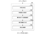
- step S2 in FIG. 2 the operation of the adjusting unit 10 of the biometric authentication device 1 (step S2 in FIG. 2) will be described in detail with reference to FIG.
- the operation of the adjustment unit 10 of the biometric authentication device 1 first, the operation of the adjustment unit 10 when the person of the subject to be biometric authentication is stopped is described, and then the adjustment unit when the person moves. The operation of 10 will be described.
- the focusing determination unit 102 analyzes the image information output from the image information acquisition unit 101, and performs focusing determination, which is a determination of whether or not the subject is in focus (step S21).
- focusing determination a focusing index indicating whether or not the image is in focus in a predetermined area is calculated.
- the in-focus index is an index that becomes higher as the image is in focus, and is, for example, a value that evaluates the power of a high-frequency component of an image and the amount of an edge component. There are various methods for determining whether or not the subject is in focus using the focus index.
- the focus control is used to take a picture while shifting the focus position, obtain the focus index, and determine the maximum point. You may ask for it and make a focus determination. In the latter case, it is not immediately possible to know whether or not the image is in focus on the spot, and after taking a picture by moving the focus position several times, the image in focus is known. Therefore, it is necessary for the image selection unit 107, which will be described later, to temporarily hold an image that may be selected as an in-focus image.
- Focusing information is information indicating whether or not the target image is in focus. This may be binary information indicating whether it is in focus or not, or it may be a continuous value indicating the degree of focus. When it is a continuous value, for example, the above-mentioned focusing score value may be used as it is.
- an index that identifies the image with the maximum focusing index while the focus is shaken. Include (frame numbers, timestamps, etc.).
- This focusing information is information indicating the degree of focusing. The obtained focusing information is input to the correction unit 105. Further, the information indicating which frame is in focus or the information indicating the degree of focusing is output to the image selection unit 107 as selection information.
- the feature point extraction unit 103 performs face detection or head detection on the input image, and obtains a face landmark which is a position of a characteristic portion included in the face or the head (step S22).
- the face landmark may also be simply referred to as a landmark or a feature point.
- the face or head itself or its part can be detected by using a detector that has learned the feature points of the face or head or its part.
- a detector is used that extracts Histograms of Oriented Gradients (HOG) features, which is one of the features extraction methods from images, and detects them based on the extracted features.
- HOG Histograms of Oriented Gradients
- a detector that directly detects from an image using CNN (Convolutional Neural Network), which is a kind of image recognition by machine learning, may be used.
- the feature point extraction unit 103 may obtain the position information (position coordinates on the image) of only the feature points used for estimating the distance to the subject in the distance estimation unit 104.
- the position information position coordinates on the image
- the pupils of both eyes are set as feature points and the positions thereof are obtained.
- the position of the pupil instead of the position of the pupil, the position of other feature points of the eye (inner eye angle, outer eye angle, etc.) may be obtained, and the distance between these feature points may be used instead of the inter-eye distance.
- the distance to other feature points such as the nose and mouth may be used instead of the eyes, and in that case, the position of the feature point to be used may be obtained.
- the obtained landmark position information is output to the distance estimation unit 104.
- the distance estimation unit 104 estimates the distance to the subject from the obtained landmark position information (step S23). Assuming that the individual difference in the size of the human face is not large, the distance from the subject to the face can be roughly estimated from the distance between the positions of the feature points. As described above, various feature points can be used, but in the following, as an example, the pupils of both eyes are used as feature points, and the distance to the subject is used using the interpupillary distance, which is the distance between the pupils. The case of obtaining is described.
- the distance estimation unit 104 may obtain a relational expression between the eye-to-eye distance and the distance from the camera to the subject in advance, and obtain the distance to the subject based on the formula. That is, if the distance between the eyes is d and the estimated distance to the subject is D E , the relational expression can be expressed as Equation 1.
- This function f (d) is obtained in advance and used.
- the function f (d) may be approximated by a straight line obtained by linear regression, or it may be obtained by applying a polynomial or other mathematical formula. Alternatively, it may be expressed by combining those approximated for each section.
- the estimated distance to the subject obtained in this way is output to the correction unit 105 as estimated distance information.
- the correction unit 105 generates information on the correction distance for correcting the distance to the subject based on the estimated distance information and the focusing information (step S24). The processing of the correction unit 105 will be described in detail separately.
- the focus control unit 106 generates control information for controlling the focus of the image pickup apparatus 2 based on the correction distance information (step S25). As described above, this control information is generated according to the method of focusing by the image pickup apparatus 2. Further, the focus control unit 106 outputs the generated control information to the image information acquisition unit 101. The image information acquisition unit 101 controls the focus of the image pickup apparatus 2 using the obtained control information, and obtains a new image having a different focus from the image for which the focus is controlled.
- the correction unit 105 generates information on the correction distance for correcting the distance to the subject based on the estimated distance information and the focusing information.
- the correction unit 105 may use the estimated distance input in the past and the corresponding correction distance and focusing information instead of the estimated distance and focusing information at the current time. Therefore, it is assumed that the correction unit 105 holds the results of the estimated distance input and the output correction distance within a certain period of time in association with the time.
- the method of correcting the distance based on the estimated distance D E and obtaining the corrected distance D C is arbitrary. In the following, a case where the correction distance D C is obtained by adding the difference distance ⁇ D to the estimated distance D E will be described.
- the correction method is not limited to the method described below.
- the operation of the correction unit 105 is roughly classified into a focusing distance search mode and a focusing tracking mode.
- Focusing distance search mode is a mode for obtaining the focusing differential distance [Delta] D f in a state of focusing the difference metric [Delta] D f corresponds to the in-focus state has not been obtained.
- the focusing tracking mode is a mode in which after the focusing difference distance ⁇ D f is obtained, the distance is corrected using the value and the focusing state is maintained.
- the operation of the correction unit 105 in each mode will be described.
- the focusing difference distance ⁇ D f is indefinite, so the camera operates in the focusing distance search mode.
- the correction distance D C is calculated from the estimated distance D E according to a certain rule.
- the variation from the initial estimated distance estimate the variation from the initial estimated distance (estimated distance at time t 0)
- the correction distance Dc can be expressed as Equation 2.
- g 1 represents the variation obtained in the focusing distance search mode.
- n indicates the number of times the processing shown in FIG. 3 was performed from the time t 0 at which the initial estimated distance was obtained
- t n indicates the time at the nth time.
- N 1 is a value that determines the average number of continuations until the input focusing information indicates that the focus has been achieved in the focusing distance search mode as an index.
- the value is smaller than the average number of continuations of the number of repetitions until the focusing information indicates that the focus is in focus, for example, a value approximately half of the average number of continuations.
- the estimated distance D E at time t j (t j) is changed more than a certain percentage from the initial estimated distance D E (t 0) is the estimated distance D E at time t j a (t j) You may try the search again based on the reference.
- the difference distance ⁇ D at that time is obtained as the focusing difference distance ⁇ D f .
- the difference between the correction distance and the estimated distance at time t i is the individual. It means that the distance is different based on the difference. Therefore, the value obtained by subtracting the estimated distance from the correction distance shown in Equation 4 is obtained as the focusing difference distance ⁇ D f , and is stored as the difference distance information for the target person.
- the above focusing difference distance may depend on the estimated distance D E. Therefore, as shown in Equation 6, the focusing difference distance ⁇ D f is regarded as a function of the estimated distance D E , and each time the focus is reached, the set of the difference distance and the estimated distance at the time of focusing is accumulated and this function is obtained. You may do so.
- the difference distance information is information that describes a function for obtaining the focusing difference distance ⁇ D f from the estimated distance D E.
- the distance is controlled to be constant regardless of the estimated distance D E , and if the focus is lost when the D E changes, the focus position is adjusted by slightly shaking the focus position as described later, and the focus difference is adjusted. Find the distance. This is associated with D E and stored and used. At this time, fitting by a regression line may be performed and the coefficient may be held as the difference distance information.
- the focusing information obtained as a result of controlling by the correction distance obtained in this way indicates that the focus is not sufficiently focused, the distance is further changed slightly before and after that. For example, it is conceivable to control according to Equation 7 using a function g 2 (t) whose range is narrower than g 1 (t).
- g 2 represents the fluctuation amount obtained in the focusing tracking mode.
- g 2 (t) for example, 0 ⁇
- FIG. 4 is a flowchart showing the processing flow of the correction unit 105.
- the correction unit 105 checks whether or not there is difference distance information (whether or not it has already been calculated) (step S24a). When the difference distance information has not been obtained yet (step S24a: No), the correction unit 105 calculates the focus difference distance in the focus distance search mode (step S24b). When the difference distance information has already been obtained (step S24a: Yes), the correction unit 105 adjusts the focus difference distance in the focus tracking mode (step S24c). Then, the correction unit 105 calculates the correction distance from the obtained focusing difference distance (step S24d).
- the above process is repeated until an image focused to the extent that sufficient accuracy can be obtained in biometric authentication is obtained, or a predetermined number of times.
- the correction distance information obtained in this way is output to the focus control unit 106.
- biometric authentication device 1 when the subject is not stationary at a fixed place but the subject moves.
- biometric authentication is performed by changing the position of the focal point according to the movement of a person.
- a person performs authentication while moving toward the image pickup apparatus 2 will be described. It should be noted that the application is not limited to the case where the person moves toward the image pickup apparatus 2, and the same applies to any case where the movement of the person can be predicted.
- the distance to the subject decreases with the passage of time. Therefore, if the focus is set to a distance shorter than the current subject distance, the subject distance becomes the set distance at a slightly later point, and the in-focus image can be acquired. Then, after the in-focus image is acquired, the focus is set so that the in-focus image can be acquired in a little later time at the subject distance assumed at a little later time. That is, the correction distance is calculated so that the in-focus image can be acquired in the previous time.
- the walking speed of the person or the time when the next new image is acquired so that the in-focus image can be acquired at the time before the next image is acquired.
- the correction distance is calculated by using the information that is the basis of the prediction for acquiring the in-focus image, such as the predicted movement distance of the person. Then, after acquiring the in-focus image, the same procedure is repeated. This makes it possible to acquire in-focus images at a plurality of positions and perform biometric authentication.
- the operation of the correction unit 105 that realizes this will be described.
- the correction distance D C (t n ) is calculated by the number tens, where L is a value slightly larger than the maximum value of
- This fixed value is output as a correction value until it indicates that the focusing information is in focus.
- the focusing information is in focus, it is obtained as the focusing difference distance ⁇ D f by the equation 4 in the same manner as described above.
- the in-focus tracking mode In the in-focus tracking mode, the subject distance at a point slightly ahead is predicted, and the correction distance D C is set so that the subject is in focus at that point. If the time of the focused image is t i , then the elapsed time from the time t i of the scheduled time to acquire the in-focus image (this is t m ) is calculated, and the distance that can be moved during that time is calculated. Find and find a distance slightly larger than that distance as L M. Then, the correction distance D C is calculated by the equation 11.
- L M is represented by the equation 12.
- the walking speed V of the person an average value may be used, or the walking speed V may be estimated and used from the time variation of the inter-eye distance d. That is, the walking speed V may be estimated and used by using the calculation history of the estimated distance D E at a time earlier than this.
- the correction distance D C obtained in this way is output until the subject distance becomes this value and the focusing information by the focusing determination unit 102 indicates that the subject is in focus.
- L M is calculated again in the same manner as described above, and the correction distance Dc is calculated.
- the focusing difference distance ⁇ D f may also be calculated and updated.
- the value obtained at a close position is generally more accurate than the focusing difference distance obtained at a position where the subject is far, because the accuracy of the relative position between the face landmarks is improved. Therefore, by appropriately updating the focusing difference distance ⁇ D f, the estimation accuracy of the focusing position can be improved, the number of times biometric authentication can be performed increases, and the failure rate of biometric authentication can be reduced.
- the operations other than the correction unit 105 are the same as when the person is stopped.
- the search in the focusing distance search mode by the correction unit 105 can be executed even before the person approaches a distance suitable for biometric authentication.
- the mode shifts to the focusing tracking mode, so that faster authentication becomes possible.
- Biometrics can be performed faster. Therefore, even if the acquisition of the biometric image fails once, it can be recovered by the subsequent image acquisition, and the biometric authentication can be performed more reliably.
- FIG. 5 shows a functional block diagram of the biometric authentication device 1 according to the second embodiment.
- the difference from the functional block diagram of the biometric authentication device 1 in the second embodiment shown in FIG. 1 is in the correction unit 105a, and the other processing units are the same.
- the correction unit 105a of the biometric authentication device 1 in the second embodiment receives the input of the difference distance information
- the correction unit 105a corrects the estimated distance based on the input difference distance information and generates the correction distance.
- FIG. 6 shows the operation of the adjusting unit 10a of the biometric authentication device 1 in the second embodiment.
- the difference in operation of the biometric authentication device 1 from the adjusting unit 10 in the first embodiment is the operation of the correction unit 105a in step S24a.
- the operation of the correction unit 105a in step S24a will be described.
- the operation of the correction unit 105a receives input of the difference distance information from the portable medium 3 and generates the correction distance using the input difference distance information, as compared with the operation of the correction unit 105 in the first embodiment.
- the difference distance information is basically the same as the difference distance information described in the first embodiment, and is information for correcting individual differences.
- the difference distance information obtained at the time of the previous authentication is stored in the portable medium 3 such as a smartphone, and is read and input by the system at the time of the next authentication.
- the correction unit 105a when registering biometric authentication, if the difference distance information is obtained by the same procedure as at the time of collation, the correction unit 105a stores the difference distance information obtained at that time and uses it at the time of collation. It may be. Further, instead of storing the difference distance information itself, the distance between the eyes and the like is measured or estimated together at the time of registration and stored in the portable medium 3, and then the difference distance information is obtained. May be good.
- the correction unit 105a calculates the correction distance based on the value. That is, the correction distance is calculated according to Equation 5 from the beginning. As a result, it becomes possible to focus faster than when the difference distance information is not known, and the time required for biometric authentication can be shortened.
- FIG. 7 shows a functional block diagram of the biometric authentication device 1 according to the third embodiment.
- the difference from the functional block diagram of the biometric authentication device 1 in the first embodiment shown in FIG. 1 is in the image analysis unit 109 and the correction unit 105b, and the other processing units are the same.
- the image analysis unit 109 in the third embodiment at least either generates incidental information by detecting an accessory of the face in the subject or calculates information on the orientation of the face. Do one or the other.
- the correction unit 105b changes the method of calculating the correction distance based on one or both of the incidental information or the face orientation information obtained by the image analysis unit 109.
- FIG. 8 shows the operation of the adjusting unit 10b of the biometric authentication device 1 in the third embodiment.
- the difference in operation of the biometric authentication device 1 from the adjusting unit 10 in the first embodiment is the operation of the image analysis unit 109 in step S20 and the correction unit 105b in step S24b.
- the operations of the image analysis unit 109 and the correction unit 105b will be described.
- the image analysis unit 109 detects an accessory attached to the face from the image output from the image information acquisition unit 101, estimates the face orientation, and obtains the obtained accessory and orientation information (step). S20).
- the image analysis unit 109 detects whether or not there is an accessory on the face with respect to the input image.
- the accessory refers to an object attached to the face, and specifically, glasses, sunglasses, an eye patch, goggles, a mask, a nicab, and the like. This detection can be detected by using a detector learned in the same manner as general object detection.
- the image analysis unit 109 also calculates the orientation of the face. That is, it is calculated how much the direction is deviated from the front direction in the vertical direction and the horizontal direction. This can also be determined using a determination device trained for each face orientation.
- the obtained incidental information and face orientation information are output to the correction unit 105b.
- the correction unit 105b includes the estimated distance information output from the distance estimation unit 104, the focusing information output from the focusing determination unit 102, the incidental information output from the image analysis unit 109, and the face orientation information. Then, the correction distance is obtained and output to the focus control unit 106 (step S24b).
- the correction unit 105b adjusts the distance correction method based on the incidental / orientation information.
- the correction is performed in the same manner as in the correction unit 105.
- the correction unit 105b changes the correction method accordingly if there is an accessory.
- the measured inter-eye distance may deviate from the correct value due to the refraction of the spectacle lens. Therefore, this deviation is also taken into consideration when correcting.
- the correction unit 105b may control the range of the correction distance to be changed in the focusing distance search mode so as to be biased toward the closer side. good.
- the distance between the eyes may be corrected in consideration of the direction.
- the correction unit 105b adds the correction amount due to the inclination to the difference distance to perform the correction.
- the corrected inter-eye distance d'shown in Equation 13 is used instead of the inter-eye distance d.
- the correction unit 105b may be capable of inputting the difference distance as in the correction unit 105a described in the second embodiment. In this case, the correction unit 105b generates the correction distance using the input difference distance information. In this way, even when an accessory is attached to the face or the orientation is not the front, the focus can be achieved at high speed by performing the correction in consideration of the fact.
- FIG. 9 shows a functional block diagram of the biometric authentication device 1 according to the fourth embodiment.
- the difference from the functional block diagram of the biometric authentication device 1 in the third embodiment shown in FIG. 7 is that there is a focusing determination unit 102c, and the other processing units are the same.
- the focusing determination unit 102c in the fourth embodiment changes the selection criteria of the image for biometric authentication from the image of the subject based on the information on the incidental objects or the orientation information of the face obtained by the image analysis unit 109.
- FIG. 10 shows the operation of the adjusting unit 10c of the biometric authentication device 1 in the fourth embodiment.
- the difference in operation of the biometric authentication device 1 from the adjusting unit 10b in the third embodiment is the operation of the focusing determination unit 102c in step S21c.
- the operations of the image analysis unit 109 and the focus determination unit 102c will be described.
- the image analysis unit 109 detects ancillary objects attached to the face from the image output from the image information acquisition unit 101, estimates the face orientation, and provides information on the obtained ancillary objects and information on the face orientation. (Step S20). The details of the operation of the image analysis unit 109 are as described in the third embodiment.
- the focusing determination unit 102c generates focusing information and selection information based on the image output from the image information acquisition unit 101, information on incidental objects output from the image analysis unit 109, and face orientation information. Focusing information is output to the correction unit 105b, and selection information is output to the image selection unit 107 (step S21c). That is, when the focusing determination unit 102c indicates that there is no accessory on the face and the orientation of the face is front from the information on the incidental objects and the information on the orientation of the face, the operation of the focusing determination unit 102c is Performs the same operation as. On the other hand, when indicating that there is an accessory such as eyeglasses, the focusing determination unit 102c may change the focusing determination method or the selection information determination method.
- the biometric authentication is iris authentication
- the frame of the spectacles may be in focus and the iris may not be in focus. Therefore, when the accessory information includes spectacles, a position shifted slightly far from the position where the focusing score is maximized may be obtained as the focusing position.
- the selection information not only the frame having the maximum focusing index but also the frame at a position slightly farther from the focal position may be selected. By doing so, it is possible to reduce the risk that the acquired image is out of focus to the part required for biometric authentication, and it is possible to reduce the failure rate of biometric authentication when there are incidentals.
- face authentication that is, iris authentication, etc.
- iris authentication has been described as an example of biometric authentication, but the present invention is not limited to this. It can be applied as long as it is a method of authenticating using image information of a living body other than the face, and for example, it can be applied to non-contact fingerprint / palm print and vein authentication. In this case, the landmark information becomes the feature points of the palm and fingers.
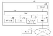
- FIG. 11 is a diagram illustrating a hardware configuration of the biometric authentication device.
- the network 11 and the camera 12 are illustrated.
- the computer 9 is an arbitrary computer.
- the computer 9 is a personal computer (PC), a server machine, a tablet terminal, a smartphone, or the like.
- the computer 9 may be a dedicated computer designed to realize the biometric authentication device 1, or may be a general-purpose computer.
- the computer 9 includes a bus 91, a processor 92, a memory 93, a storage device 94, an input / output interface 95, and an external interface 96.
- the bus 91 is a data transmission path for the processor 92, the memory 93, the storage device 94, the input / output interface 95, and the external interface 96 which also serves as a network interface to transmit and receive data to and from each other.
- the method of connecting the processors 92 and the like to each other is not limited to the bus connection.
- the processor 92 is various processors such as a CPU (Central Processing Unit), a GPU (Graphics Processing Unit), or an FPGA (Field-Programmable Gate Array).
- the memory 93 is a main storage device realized by using RAM (Random Access Memory) or the like.
- the storage device 94 is an auxiliary storage device realized by using a hard disk, an SSD (Solid State Drive), a memory card, a ROM (Read Only Memory), or the like.
- the input / output interface 95 is an interface for connecting the computer 9 and the input / output device.
- an input device such as a keyboard and an output device such as a display device are connected to the input / output interface 95.
- the external interface 96 is an interface for connecting the computer 9 to the network 11 or the like.
- FIG. 11 shows a case where the external interface 96 is a network interface and is connected to the network 11, but the present invention is not limited to this.
- this network is, for example, LAN (Local Area Network) or WAN (Wide Area Network).
- the method of connecting the external interface 96 to the network may be a wireless connection or a wired connection.
- the external interface 96 may be an interface for directly connecting an external device instead of a network interface.
- it may be directly connected to the camera 12 without going through a network by USB (Universal Serial Bus), IEEE1394, or the like.
- a camera 12 is connected to the network 11, and the computer 9 and the camera 12 can communicate data via the network 11.
- the camera 12 corresponds to the image pickup device 2 of the biometric authentication device 1.
- the storage device 94 stores a program module that realizes each processing unit of the biometric authentication device 1.
- the processor 92 realizes the function corresponding to each program module by reading each of these program modules into the memory 93 and executing the module. Note that some functions of the biometric authentication device 1 may be executed on the camera 12 side. That is, even if a processor, a storage device, and a memory are stored inside the camera 12, all or part of the processing of each processing unit of the biometric authentication device 1 is executed by using these components. good.
- the image information acquisition unit 101, the focusing determination unit 102, the feature point extraction unit 103, the distance estimation unit 104, the correction unit 105 (105a), the focus control unit 106, the image selection unit 107, and the biometric authentication unit 108 are on the camera 12 side.
- other processing may be executed on the computer 9 side.
- the processing of the feature point extraction unit 103 may also be executed on the camera 12 side, and other processing may be executed on the computer 9 side.
- all the processes other than the biometric authentication unit 108 may be executed on the camera side.
- FIG. 12 is a diagram showing a minimum configuration diagram of the biometric authentication device 1.
- the biometric authentication device 1 includes a correction unit 105, a focus control unit 106, and a focus determination unit 102.
- FIG. 13 is a diagram showing a processing flow diagram of the biometric authentication device in the minimum configuration shown in FIG.
- the correction unit 105 is a difference distance information obtained based on the focusing information indicating the degree of focusing in the image of the subject to be bioauthenticated and the estimated distance to the subject obtained from the distance between the feature points of the image.
- the correction that corrects the deviation between the estimated distance and the focusing distance with respect to the subject based on the difference distance information by using the difference distance information indicating the deviation between the estimated distance and the focusing distance with respect to the subject.
- Generate a distance step S101).
- the focus control unit 106 generates information for controlling the focus of the subject at the time of image acquisition based on the correction distance (step S102).
- the focusing determination unit 102 generates information for selecting an image to be biometrically authenticated from the images of the subject taken after controlling the focus (step S103). The above process may be repeated until a focused image capable of performing authentication with a predetermined accuracy in biometric authentication is obtained.
- the biometric authentication device 1 will be able to focus at high speed in consideration of individual differences. Therefore, it is possible to focus at high speed when focusing and shooting from the second time onward, and even if the first image acquisition fails, biometric authentication can be performed at high speed.
- biometric authentication device 1 does not require an additional device, and has an effect that the image quality can be improved, which leads to improvement in the accuracy of biometric authentication.
- the biometric authentication device 1 it becomes possible to focus at high speed and execute biometric authentication without a sensor for measuring the distance to the subject to be biometric authentication. Further, it can be used regardless of whether the person to be biometrically authenticated is stationary or moving. Therefore, it can be used for a biometric authentication system for payment, a biometric authentication system for a gate while walking, and the like.
- Biometric authentication device 2 Imaging device 3 Portable medium 10, 10a, 10b, 10c Adjustment unit 101 Image information acquisition unit 102, 102c Focus determination unit 103 Feature point extraction unit 104 Distance estimation unit 105, 105a, 105b Correction unit 106 Focus Control unit 107 Image selection unit 108 Biometrics unit 109 Image analysis unit
Landscapes
- Engineering & Computer Science (AREA)
- Theoretical Computer Science (AREA)
- Computer Security & Cryptography (AREA)
- Physics & Mathematics (AREA)
- General Physics & Mathematics (AREA)
- Signal Processing (AREA)
- Multimedia (AREA)
- Computer Hardware Design (AREA)
- Software Systems (AREA)
- General Engineering & Computer Science (AREA)
- Measurement Of The Respiration, Hearing Ability, Form, And Blood Characteristics Of Living Organisms (AREA)
- Collating Specific Patterns (AREA)
- Studio Devices (AREA)
- Image Input (AREA)
Abstract
生体認証装置は、生体認証の対象となる被写体の画像における合焦の度合を示す合焦情報と画像の特徴点間の距離より求めた被写体までの推定距離とに基づき得られる差分距離情報を利用して、推定距離と被写体に対する合焦距離のずれを差分距離情報に基づき補正した補正距離を生成する。生体認証装置は、補正距離に基づいて被写体の画像取得時における焦点を制御するための情報を生成し、焦点の制御を行った後に撮影された被写体の画像の中から、生体認証を行う画像を選択するための情報を生成する。
Description
本発明は、生体認証装置、生体認証方法、および生体認証用プログラムに関する。
顔や、虹彩などのその一部を使って人物を認識する方式が数多く提案されている。これらの方式では、顔やその一部をカメラで撮影し、個人を識別可能な情報を抽出し、個人の照合を行う。この際、精度の高い認証を行うには、高画質な画像を得る必要がある。
特許文献1では、センサから顔の額、鼻頭といった各特徴点までの距離を利用した認証方法が記載されている。特許文献2では、距離センサを用いて撮像装置の調整をおこなう認証システムを開示している。特許文献3は、主撮像部と副撮像部から得られる2つの画像から算出された視差量等の誤差を補正した距離情報を求めることで光学系の変位や変形による像ズレが発生した状態でも高精度かつ高速なフォーカス制御が可能な制御装置を開示している。
この開示は、上記関連する技術を改善する生体認証装置、生体認証方法、および生体認証用プログラムを提供することを目的としている。
本開示の一実施形態による生体認証装置は、生体認証の対象となる被写体の画像における合焦の度合を示す合焦情報と前記画像の特徴点間の距離より求めた前記被写体までの推定距離とに基づき得られる差分距離情報であって、前記推定距離と前記被写体に対する合焦距離のずれを示す前記差分距離情報を利用して、前記推定距離と前記被写体に対する前記合焦距離のずれを前記差分距離情報に基づき補正した補正距離を生成する補正手段と、前記補正距離に基づいて、前記被写体の画像取得時における焦点を制御するための情報を生成する焦点制御手段と、前記焦点の制御を行った後に撮影された前記被写体の画像の中から、生体認証を行う画像を選択するための情報を生成する合焦判定手段と、を備える。
本開示の一実施形態によるコンピュータによる生体認証方法は、生体認証の対象となる被写体の画像における合焦の度合を示す合焦情報と前記画像の特徴点間の距離より求めた前記被写体までの推定距離とに基づき得られる差分距離情報であって、前記推定距離と前記被写体に対する合焦距離のずれを示す前記差分距離情報を利用して、前記推定距離と前記被写体に対する前記合焦距離のずれを前記差分距離情報に基づき補正した補正距離を生成し、前記補正距離に基づいて、前記被写体の画像取得時における焦点を制御するための情報を生成し、前記焦点の制御を行った後に撮影された前記被写体の画像の中から、生体認証を行う画像を選択するための情報を生成する。
本開示の一実施形態による記録媒体は、コンピュータを、生体認証の対象となる被写体の画像における合焦の度合を示す合焦情報と前記画像の特徴点間の距離より求めた前記被写体までの推定距離とに基づき得られる差分距離情報であって、前記推定距離と前記被写体に対する合焦距離のずれを示す前記差分距離情報を利用して、前記推定距離のずれを前記差分距離情報に基づき補正した補正距離を生成する補正手段と、前記補正距離に基づいて、前記被写体の画像取得時における焦点を制御するための情報を生成する焦点制御手段と、前記焦点の制御を行った後に撮影された前記被写体の画像の中から、生体認証を行う画像を選択するための情報を生成する合焦判定手段と、として機能させるプログラムを記録する。
以下、本開示の一実施形態による生体認証装置を、図面を参照して説明する。
(第1の実施の形態)
図1は第1の実施の形態による生体認証装置1の構成を示す図である。図1において、符号1は生体認証装置を、符号2は撮像装置を示す。生体認証装置1は、撮像装置2により撮影された映像より画像を取得し、得られた画像を用いた生体認証を行う。撮像装置2は、生体認証の対象となる生体部分を含む被写体を撮像可能な装置である。なお、撮像装置2は、図1において生体認証装置1と別の装置として図示しているが、撮像装置2は生体認証装置1の一部であってもよい。
図1は第1の実施の形態による生体認証装置1の構成を示す図である。図1において、符号1は生体認証装置を、符号2は撮像装置を示す。生体認証装置1は、撮像装置2により撮影された映像より画像を取得し、得られた画像を用いた生体認証を行う。撮像装置2は、生体認証の対象となる生体部分を含む被写体を撮像可能な装置である。なお、撮像装置2は、図1において生体認証装置1と別の装置として図示しているが、撮像装置2は生体認証装置1の一部であってもよい。
生体認証装置1は、画像情報取得部101、調整部10、画像選択部107、生体認証部108を備える。
画像情報取得部101は、撮像装置2を制御して得られた映像から画像を取得する。画像情報取得部101は、得た画像の情報を調整部10と画像選択部107へ出力する。また、画像情報取得部101は、調整部10からの焦点制御に関する情報を利用して、撮像装置2の焦点制御を行い、新たな画像を取得する。
調整部10は、画像情報取得部101で得た画像における合焦の程度を判定するとともに、画像に写る特徴点間の距離を用いて被写体までの推定距離を求め、求めた推定距離と被写体に対する合焦距離のずれを示す差分距離を求める。また、調整部10は、求めた推定距離のずれを差分距離情報に基づいて補正した補正距離を生成し、補正距離に基づいて被写体の画像取得時における焦点を制御するための情報を生成する。調整部10は、焦点を制御するための情報を画像情報取得部101に出力する。
画像選択部107は、画像情報取得部101から出力される画像情報の中で、画像の焦点が合った生体認証を行う画像を選択画像として生体認証部108へ出力する。
生体認証部108は、画像選択部107から出力される選択画像に対して生体認証処理を行い、認証結果を生成する。
次に調整部10について説明する。調整部10は、合焦判定部102、特徴点抽出部103、距離推定部104、補正部105、焦点制御部106を含む。
合焦判定部102は、画像情報取得部101から出力される画像情報を解析して焦点が合っているかを判定し、焦点が合っているかを表す合焦情報を補正部105へ出力する。また、合焦判定部102は、焦点があっているかの判断結果より、焦点があった画像またはフレームを特定するための情報である選択情報を生成し、画像選択部107に出力する。
特徴点抽出部103は、画像情報取得部101から出力される画像情報から顔のランドマークとなる特徴点を検出し、距離推定部104へ顔ランドマークの位置情報を出力する。
合焦判定部102は、画像情報取得部101から出力される画像情報を解析して焦点が合っているかを判定し、焦点が合っているかを表す合焦情報を補正部105へ出力する。また、合焦判定部102は、焦点があっているかの判断結果より、焦点があった画像またはフレームを特定するための情報である選択情報を生成し、画像選択部107に出力する。
特徴点抽出部103は、画像情報取得部101から出力される画像情報から顔のランドマークとなる特徴点を検出し、距離推定部104へ顔ランドマークの位置情報を出力する。
距離推定部104は、特徴点抽出部103から出力されるランドマーク位置情報に基づいて、ランドマーク位置間の距離から被写体までの距離を推定し、推定距離情報を、補正部105へ出力する。
補正部105は、距離推定部104から出力される推定距離情報と、合焦判定部102から出力される合焦情報とに基づいて、被写体までの距離を補正し、得られた補正距離情報を焦点制御部106へ出力する。
焦点制御部106は、焦点制御部106から出力される補正距離情報に基づいて、レンズの焦点を制御するための制御情報を生成し、画像情報取得部101へ出力する。
補正部105は、距離推定部104から出力される推定距離情報と、合焦判定部102から出力される合焦情報とに基づいて、被写体までの距離を補正し、得られた補正距離情報を焦点制御部106へ出力する。
焦点制御部106は、焦点制御部106から出力される補正距離情報に基づいて、レンズの焦点を制御するための制御情報を生成し、画像情報取得部101へ出力する。
次に、図1に示す生体認証装置1の動作について図2を用いて説明する。まず、生体認証としては、顔や頭部の全部、あるいは一部を用いた生体認証を対象にする。例えば、顔認証、虹彩認証、目の周囲領域での認証、耳認証などが対象に含まれる。
画像情報取得部101は、撮像装置2を制御して、被写体の人物の映像を撮影し、画像の取得を行う(ステップS1)。ここで、撮像装置2としては、上述の生体認証に用いる部位が、認証に可能な解像度、画質で撮影できるものであれば、どのようなものでもよい。例えば、USBカメラであってもよいし、IPカメラやWebカメラ、CCTVカメラであってもよい。ただし、近赤外光を用いて生体認証を行う場合(虹彩認証など)には、カメラは近赤外の領域の映像を、生体認証に必要な解像度、画質で撮影できるものである必要がある。
また、撮像装置2は、被写体までの距離に応じて焦点を調節する仕組みを有する。この仕組みとしては、従来オートフォーカスで用いている任意の機構を用いることができる。また、液体レンズなど、近年使われるようになってきた新しいデバイスを用いてもよい。撮像装置2は、少なくとも、外部から焦点を制御できるようになっており、焦点制御部106から入力される制御情報に従って焦点が制御可能な装置とする。焦点制御の例としては、レンズの距離を調節するフォーカスリングの回転角、あるいはフォーカスリングを回転させるのに用いるフォーカスモータの回転角を制御情報に含む。また、液体レンズの場合であれば、制御情報は液体レンズの制御電圧情報を含み、制御電圧を指定された値に変更し、画像を取得する。
画像情報取得部101で取得された画像は、調整部10と画像選択部107へ出力する。また、調整部10では、合焦判定部102と特徴点抽出部103とにおいて取得された画像を用いた処理が行われる。
調整部10は、画像情報取得部101で得た画像を利用して、被写体の画像取得時における焦点を制御するための情報を生成する(ステップS2)。より具体的には、調整部10は、画像情報取得部101で得た画像における合焦の度合を判定するとともに、画像の特徴点間の距離より求めた被写体までの推定距離を求め、求めた推定距離と被写体に対する合焦距離のずれを示す差分距離情報を求める。また、調整部10は、求めた推定距離のずれを差分距離情報に基づいて補正した補正距離を生成し、補正距離に基づいて被写体の画像取得時における焦点を制御するための情報を生成する。
なお、調整部10による被写体の画像取得時における焦点の調整処理は、生体認証を定められた精度で行える程度に画像における焦点が合うまで行われる。あるいは、調整部10による被写体の画像取得時における焦点の調整処理は、定められた所定回数行われるものとする。その間、ステップS1、ステップS2のフィードバック処理が繰り返され、その後、ステップS3に進む。
なお、調整部10による被写体の画像取得時における焦点の調整処理は、生体認証を定められた精度で行える程度に画像における焦点が合うまで行われる。あるいは、調整部10による被写体の画像取得時における焦点の調整処理は、定められた所定回数行われるものとする。その間、ステップS1、ステップS2のフィードバック処理が繰り返され、その後、ステップS3に進む。
画像選択部107は、入力される画像を一定期間蓄積している。そして、調整部10の合焦判定部102から出力される焦点が合ったことを示す選択情報に基づいて、画像を選択し、出力する(ステップS3)。ここで、“画像”とは、撮像装置2でえられた映像における所定のフレーム、または、所定のフレームから取得した静止画とする。選択情報は、焦点があった画像を特定するための情報であり、焦点が合った画像のフレーム番号やタイムスタンプなどの情報である。選択情報で選択された画像は選択画像として生体認証部108へ出力される。
なお、選択する画像は1枚だけでなく、複数枚であってもよい。例えば、合焦指標が一番高くなるフレームの前後のフレームも選択するようにしてもよい。これにより、焦点のあった位置が、生体認証で用いる部位ではなく、少しずれた位置だった場合でも、生体認証に必要な部位の焦点が合った画像を取得できる可能性が高まり、生体認証で失敗する確率を低減できる。
なお、選択する画像は1枚だけでなく、複数枚であってもよい。例えば、合焦指標が一番高くなるフレームの前後のフレームも選択するようにしてもよい。これにより、焦点のあった位置が、生体認証で用いる部位ではなく、少しずれた位置だった場合でも、生体認証に必要な部位の焦点が合った画像を取得できる可能性が高まり、生体認証で失敗する確率を低減できる。
生体認証部108は、画像選択部107から出力される選択画像に対して生体認証処理を行い、認証結果を生成する(ステップS4)。より具体的には、生体認証部108は、入力される画像から用いる生体認証に応じた特徴量を抽出する。そして、あらかじめ登録されている人物の特徴量と比較し、生体認証の対象となる人物が誰であるか、あるいは誰とも合致しないかを判定する。例えば、虹彩照合の場合には、選択された画像から目領域を切り出し、虹彩の特徴量を抽出する。そして、抽出された特徴量と、あらかじめ登録されている虹彩の特徴量の比較を実施し、認証結果を生成する。
以下、生体認証装置1の調整部10の動作(図2のステップS2)について、図3を用いて詳細に説明する。生体認証装置1の調整部10の動作の説明において、最初に、生体認証の対象となる被写体の人物が止まっている場合における調整部10の動作について述べ、次に、人物が動く場合における調整部10の動作について説明する。
(被写体の人物が止まっている場合の動作)
合焦判定部102は、画像情報取得部101から出力される画像情報を解析し、焦点が合っているかの判定である合焦判定を行う(ステップS21)。合焦判定では、画像の所定領域におけるフォーカスがあっているかどうかを表す合焦指標を算出する。合焦指標は、フォーカスがあっているときほど高い値になる指標であり、例えば、画像の高周波成分の電力や、エッジ成分がどの程度あるかを評価した値である。
合焦指標を用いて焦点が合っているかどうかを判定する方式は様々である。例えば、合焦指標が所定の閾値を超えたときに焦点が合っていると判定してもよいし、焦点制御によって焦点の位置をずらしながら撮影し、合焦指標を求め、極大となる点を求めて合焦判定を行ってもよい。後者の場合は、その場ですぐに焦点が合っているかどうかがわかるわけではなく、数回焦点位置を動かして撮影した後で、焦点が合った画像がわかることになる。よって、焦点が合った画像として選択される可能性がある画像を後述の画像選択部107で一時的に保持しておく必要がある。
また、合焦判定部102は、合焦判定の結果に基づいて、合焦情報を生成し、出力する。合焦情報は、対象となる画像の焦点が合っているかどうかを表す情報である。これは、合っているか、いないかのいずれかを示す2値情報であってもよいし、または、焦点が合っている程度を表す連続値であってもよい。連続値である場合、例えば、上述の合焦スコアの値をそのまま用いてもよい。また、数回焦点を振ってその中の極大値を求める方式の場合には、合焦したかどうかの情報に加え、焦点を振った中で合焦指標が最大となった画像を識別するインデックス(フレーム番号やタイムスタンプなど)を含めるようにする。この合焦情報は合焦の度合を示す情報となる。
求まった合焦情報は、補正部105へ入力される。また、どのフレームの焦点が合っているかを示す情報、ないしは、合焦の度合を示す情報は選択情報として、画像選択部107へ出力される。
求まった合焦情報は、補正部105へ入力される。また、どのフレームの焦点が合っているかを示す情報、ないしは、合焦の度合を示す情報は選択情報として、画像選択部107へ出力される。
特徴点抽出部103は、入力された画像に対して、顔検出、あるいは頭部検出を行い、顔や頭部に含まれる特徴的な部位の位置である顔ランドマークを求める(ステップS22)。なお、以後において、顔ランドマークを単にランドマークまたは特徴点とも呼ぶこともある。
なお、顔や頭部自体、あるいはその部位の検出には、顔や頭部、あるいはその部位の特徴点を学習させた検出器を用いて行うことができる。例えば、画像からの特徴抽出方法の1つであるHOG(Histograms of Oriented Gradients)特徴量を抽出し、抽出した特徴量に基づいて検出する検出器を用いる。また、別の例として、機械学習による画像認識の一種であるCNN(Convolutional Neural Network)を用いて画像から直接検出する検出器を用いてもよい。
なお、顔や頭部自体、あるいはその部位の検出には、顔や頭部、あるいはその部位の特徴点を学習させた検出器を用いて行うことができる。例えば、画像からの特徴抽出方法の1つであるHOG(Histograms of Oriented Gradients)特徴量を抽出し、抽出した特徴量に基づいて検出する検出器を用いる。また、別の例として、機械学習による画像認識の一種であるCNN(Convolutional Neural Network)を用いて画像から直接検出する検出器を用いてもよい。
特徴点抽出部103は、これらのランドマークのうち、距離推定部104において、被写体までの距離を推定するのに用いる特徴点のみの位置情報(画像上での位置座標)を求めればよい。例えば、両目の瞳孔の間の距離である目間距離に基づいて、被写体までの距離を推定する場合には、両目の瞳孔を特徴点とし、その位置を求める。あるいは、瞳孔の位置の代わりに、目のほかの特徴点(内眼角や外眼角など)の位置を求め、これらの特徴点間の距離を目間距離の代わりに用いるようにしてもよい。あるいは、目の代わりに鼻や口など、他の特徴点との距離を代わりに用いるようになっていてもよく、その場合は用いる特徴点の位置を求めるようにすればよい。得られたランドマークの位置情報は、距離推定部104へ出力される。
距離推定部104は、求まったランドマークの位置情報から被写体までの距離を推定する(ステップS23)。人の顔の大きさの個人差は大きくないと仮定すると、特徴点の位置間の距離から、被写体から顔までの距離を大まかに推定できる。特徴点としては、上述の通り、様々なものを用いることができるが、以下では、一例として、特徴点として両目の瞳孔を用い、瞳孔間の距離である目間距離を用いて被写体までの距離を求める場合について説明する。
この場合、距離推定部104では、目間距離とカメラから被写体までの距離との関係式をあらかじめ求めておき、その式に基づいて、被写体までの距離を求めるようにすればよい。すなわち、目間距離をd、推定される被写体までの距離をDEとすると、関係式は数1のように表せる。
この関数f(d)をあらかじめ求めておき、用いるようにする。例えば、関数f(d)は線形回帰によって求めた直線で近似してもよいし、多項式やその他の数式を当てはめることによって求めるようにしてもよい。あるいは、区間ごとに近似したものを組み合わせて表現するようになっていてもよい。このようにして求まった被写体までの推定距離は推定距離情報として、補正部105へ出力される。
補正部105は、推定距離情報と合焦情報に基づいて、被写体までの距離を補正するための補正距離に関する情報の生成を行う(ステップS24)。補正部105の処理については、別途詳細に説明する。
焦点制御部106は、補正距離情報に基づいて、撮像装置2の焦点を制御するための制御情報を生成する(ステップS25)。この制御情報は、上述のように、撮像装置2で焦点を合わせる方式に応じて生成される。また、焦点制御部106は、生成した制御情報を画像情報取得部101へ出力する。なお、画像情報取得部101は、得た制御情報を用いて撮像装置2の焦点制御を行い、焦点の制御を行った映像より、焦点の異なる新たな画像を得る。
次に、補正部105の動作について、詳細に説明する。補正部105は、推定距離情報と合焦情報に基づいて、被写体までの距離を補正するための補正距離に関する情報の生成を行う。
補正部105は、補正距離に関する情報の生成において、現在時刻における推定距離と合焦情報ではなく、過去に入力された推定距離と、対応する補正距離、合焦情報も用いるとよい。このため、補正部105では、過去一定時間内に入力された推定距離と出力した補正距離の結果を、時刻と対応付けて保持しているものとする。
推定距離DEに基づいて距離を補正し、補正距離DCを求める方法は任意である。以下では、推定距離DEに差分距離ΔDを加算して、補正距離DCを求める場合について説明する。なお、補正方法は以下に説明する方法に限らない。
補正部105は、補正距離に関する情報の生成において、現在時刻における推定距離と合焦情報ではなく、過去に入力された推定距離と、対応する補正距離、合焦情報も用いるとよい。このため、補正部105では、過去一定時間内に入力された推定距離と出力した補正距離の結果を、時刻と対応付けて保持しているものとする。
推定距離DEに基づいて距離を補正し、補正距離DCを求める方法は任意である。以下では、推定距離DEに差分距離ΔDを加算して、補正距離DCを求める場合について説明する。なお、補正方法は以下に説明する方法に限らない。
補正部105の動作としては、大別すると、合焦距離探索モードと合焦追従モードとがある。合焦距離探索モードは、合焦状態に対応する合焦差分距離ΔDfが求まっていない状態で合焦差分距離ΔDfを求めるモードである。合焦追従モードは合焦差分距離ΔDfが求まった後で、その値を用いて距離を補正し、合焦状態を維持するモードである。以下では、それぞれのモードでの補正部105の動作について説明する。
(合焦距離探索モード)
初期状態では、合焦差分距離ΔDfは不定であるため、合焦距離探索モードで動作する。このモードでは、一定の規則に従って、推定距離DEから補正距離DCを求める。ここで、時刻tnにおける、初期推定距離(時刻t0のときの推定距離)からの変動分をg1(tn)とすると、補正距離Dcは数2のように表現できる。ここで、g1は、合焦距離探索モードで得られる変動分を表す。
初期状態では、合焦差分距離ΔDfは不定であるため、合焦距離探索モードで動作する。このモードでは、一定の規則に従って、推定距離DEから補正距離DCを求める。ここで、時刻tnにおける、初期推定距離(時刻t0のときの推定距離)からの変動分をg1(tn)とすると、補正距離Dcは数2のように表現できる。ここで、g1は、合焦距離探索モードで得られる変動分を表す。
数2のg1(tn)としては、例えば、数3のように距離δ1(>0)ずつ変化させていく関数を用いることができる。また、nは、初期推定距離を求めた時刻t0から図3に示す処理を行った回数を示し、tnはn回目における時刻を示す。
数3において、N1は、合焦距離探索モードにおいて、入力される合焦情報が合焦したことを示すまでの平均的な継続回数を指標として定める値である。好ましくは、合焦情報が合焦したことを示すまでの繰り返し回数の平均的な継続回数より小さな値、例えば、平均的な継続回数のおおよそ半分の値とする。これにより、推定距離DEの前後の距離を補正距離として生成することができるようになる。
このような算出は、入力される合焦情報が合焦したことを示すまで継続する。
ただし、推定距離が初期値から大きくずれた場合には、その推定値を基準として上述の処理をやり直してもよい。例えば、時刻tjでの推定距離DE(tj)が最初の推定距離DE(t0)から一定比率以上変化した場合には、時刻tjでの推定距離DE(tj)を基準にして、再度探索をやり直してもよい。
このような算出は、入力される合焦情報が合焦したことを示すまで継続する。
ただし、推定距離が初期値から大きくずれた場合には、その推定値を基準として上述の処理をやり直してもよい。例えば、時刻tjでの推定距離DE(tj)が最初の推定距離DE(t0)から一定比率以上変化した場合には、時刻tjでの推定距離DE(tj)を基準にして、再度探索をやり直してもよい。
合焦判定部102で求めた合焦情報が合焦したことを示した場合には、その時点での差分距離ΔDを合焦差分距離ΔDfとして求める。現時刻をtnとし、時刻ti(i<n)の画像において焦点が合っていたことを合焦情報が示す場合には、時刻tiでの、補正距離と推定距離の差分が、個人差等に基づく距離のずれということになる。よって、数4で示される、補正距離から推定距離を引いた値を合焦差分距離ΔDfとして求め、その対象人物に対する差分距離情報として記憶する。
(合焦追従モード)
合焦追従モードについて説明する。合焦距離探索モードによる差分距離情報が求まった後は、数5に示すように、推定距離情報に合焦差分距離ΔDfを加算することで、補正距離を算出するようにする(合焦追従モード)。
合焦追従モードについて説明する。合焦距離探索モードによる差分距離情報が求まった後は、数5に示すように、推定距離情報に合焦差分距離ΔDfを加算することで、補正距離を算出するようにする(合焦追従モード)。
あるいは、上記の合焦差分距離は、推定距離DEに依存する可能性もある。よって、合焦差分距離ΔDfを数6に示すように、推定距離DEの関数として捉え、焦点が合うたびに、あった時の差分距離と推定距離の組を蓄積し、この関数を求めるようにしてもよい。
この場合、差分距離情報は、推定距離DEから合焦差分距離ΔDfを求める関数を記載する情報になる。最初は推定距離DEによらずに一定として制御し、DEが変化したときに、焦点が合わなくなるようであれば、この後に述べるようにして焦点位置を少し振って調節し、合焦差分距離を求める。これをDEと対応付けて記憶しておき用いるようにする。この際、回帰直線によるフィッティングを行い、その係数を差分距離情報として保持していてもよい。
このようにして求まった補正距離によって制御した結果として得られる合焦情報が、焦点が十分に合わないことを示す場合には、さらにその前後で距離を少しだけ振るようにする。例えば、g1(t)よりも値域が狭い関数g2(t)を用いて、数7に従って制御することが考えられる。ここで、g2は、合焦追従モードで得られる変動分を表す。
このようにして求まった補正距離によって制御した結果として得られる合焦情報が、焦点が十分に合わないことを示す場合には、さらにその前後で距離を少しだけ振るようにする。例えば、g1(t)よりも値域が狭い関数g2(t)を用いて、数7に従って制御することが考えられる。ここで、g2は、合焦追従モードで得られる変動分を表す。
関数g2(t)としては、例えば、0<|δ2|<|δ1|、0<N2<N1とし、数8や数9のような関数を用いることが考えられる。
これにより、推定距離DEとΔDf前により求められる補正距離DCに対して前後距離での微調整を行った、より精度の高い補正距離DC(tn)の取得が可能となる。そして、合焦したときのDE(tn)とΔDf+g2(tn)の値を関連付けて記憶し、それ以降の差分距離の計算で用いるようにする。
次に、上述の補正部105の動作を、フローチャートを用いて説明する。図4は、補正部105の処理フローを表すフローチャートである。
補正部105は、差分距離情報があるかどうか(すでに算出済みかどうか)をチェックする(ステップS24a)。差分距離情報がまだ求まっていない場合(ステップS24a:No)、補正部105は、合焦距離探索モードで合焦差分距離を算出する(ステップS24b)。
差分距離情報がすでに求まっている場合(ステップS24a:Yes)は、補正部105は、合焦追従モードで合焦差分距離の調整を行う(ステップS24c)。そして、補正部105は、求めた合焦差分距離から補正距離の算出を行う(ステップS24d)。
補正部105は、差分距離情報があるかどうか(すでに算出済みかどうか)をチェックする(ステップS24a)。差分距離情報がまだ求まっていない場合(ステップS24a:No)、補正部105は、合焦距離探索モードで合焦差分距離を算出する(ステップS24b)。
差分距離情報がすでに求まっている場合(ステップS24a:Yes)は、補正部105は、合焦追従モードで合焦差分距離の調整を行う(ステップS24c)。そして、補正部105は、求めた合焦差分距離から補正距離の算出を行う(ステップS24d)。
以上の処理を、生体認証において十分な精度が得られる程度に焦点の合った画像が得らえるまで、あるいは、予め定められた回数、繰り返す。このようにして得られた補正距離情報は焦点制御部106へ出力される。
(被写体の人物が動く場合の動作)
次に、被写体の人物は一定の場所で静止しているのではなく、被写体が動く場合における生体認証装置1の動作について述べる。例えば、被写体となる人物がゲートにおいて歩きながら認証を行う等の場合には、人物と撮像装置2の距離は人物が動くことによって変化する。そこで、人の動きに合わせて焦点の位置を変化させ、生体認証を行う。以下では、人物が撮像装置2の方へ向かって移動しながら認証を行う場合について述べる。なお、人物が撮像装置2の方へ向かって移動する場合に限らず、人物の動きの予測が可能な任意の場合にも同様に適用可能である。
次に、被写体の人物は一定の場所で静止しているのではなく、被写体が動く場合における生体認証装置1の動作について述べる。例えば、被写体となる人物がゲートにおいて歩きながら認証を行う等の場合には、人物と撮像装置2の距離は人物が動くことによって変化する。そこで、人の動きに合わせて焦点の位置を変化させ、生体認証を行う。以下では、人物が撮像装置2の方へ向かって移動しながら認証を行う場合について述べる。なお、人物が撮像装置2の方へ向かって移動する場合に限らず、人物の動きの予測が可能な任意の場合にも同様に適用可能である。
被写体となる人物が撮像装置2の方へ向かって移動する場合、時間の経過とともに被写体までの距離(以後単に被写体距離とも呼ぶ)は減少する。よって、現時点での被写体距離よりも短い距離で焦点が合うように設定しておけば、少し先の時点で被写体距離が設定した距離となり、合焦画像を取得できる。そして、合焦画像を取得した後は、また少し先の時間で合焦画像を取得できるように、少し先の時点で想定される被写体距離で焦点が合うように設定する。すなわち、先の時間で合焦画像が取得できるように補正距離を算出する。より具体的には、例えば、人物が移動する場合において、次の画像が取得される先の時間にて合焦画像が取得できるよう、人物の歩行速度や次の新たな画像の取得時までに予測される人物の移動距離など、合焦画像を取得するための予測の基となる情報を利用して、補正距離を算出する。
そして、合焦画像を取得した後は、同様のことを繰り返す。これにより、複数の位置で合焦画像を取得し、生体認証を行えるようになる。以下では、これを実現する補正部105の動作について説明する。
そして、合焦画像を取得した後は、同様のことを繰り返す。これにより、複数の位置で合焦画像を取得し、生体認証を行えるようになる。以下では、これを実現する補正部105の動作について説明する。
(合焦距離探索モード)
補正部105では、合焦距離探索モードのときは、合焦差分距離ΔDfが求まっていない。そこで、個人差によって生じ得る|ΔDf|の最大値よりも少し大きな値をLとして、数10によって、補正距離DC (tn)を算出する。
補正部105では、合焦距離探索モードのときは、合焦差分距離ΔDfが求まっていない。そこで、個人差によって生じ得る|ΔDf|の最大値よりも少し大きな値をLとして、数10によって、補正距離DC (tn)を算出する。
合焦情報が合焦したことを示すまでは、この固定値を補正値として出力する。合焦情報が合焦したことを示した場合は、上述と同様にして、数4によって、合焦差分距離ΔDfとして求める。
(合焦追従モード)
合焦追従モードでは、少し先の時点における被写体距離を予測し、その時点で焦点が合うように補正距離DCを設定する。焦点が合った画像の時刻をtiとすると、次に合焦画像を取得する予定時刻(これをtmとする)の、時刻tiからの経過時間を求め、その間に移動し得る距離を求め、その距離より少し大きい距離をLMとして求める。そして、補正距離DCを数11によって算出する。
合焦追従モードでは、少し先の時点における被写体距離を予測し、その時点で焦点が合うように補正距離DCを設定する。焦点が合った画像の時刻をtiとすると、次に合焦画像を取得する予定時刻(これをtmとする)の、時刻tiからの経過時間を求め、その間に移動し得る距離を求め、その距離より少し大きい距離をLMとして求める。そして、補正距離DCを数11によって算出する。
ここで、人物の歩行速度をV、マージンをδ3 (>0)とすると、LMは数12で表される。
なお、人物の歩行速度Vとしては、平均的な値を用いてもよいし、目間距離dの時刻変動から歩行速度Vを推定して用いるようにしてもよい。すなわち、これより以前の時刻における推定距離DEの算出履歴を用いて歩行速度Vを推定し、用いるようにしてもよい。
このようにして求めた補正距離DCは、被写体距離がこの値になり、合焦判定部102による合焦情報は焦点が合ったことを示すまで出力される。合焦後は、上述と同様にして、再度LMを求め、補正距離Dcを算出する。この際、合焦差分距離ΔDfも合わせて算出し、更新するようにしてもよい。被写体が遠い位置で求まった合焦差分距離よりも、近い位置で求まった値の方が、顔ランドマーク間の相対位置の精度が向上することによって一般的に精度がよくなる。よって、合焦差分距離ΔDfも適切に更新することで合焦位置の推定精度が上がり、生体認証を実行できる回数が増え、生体認証の失敗率を低減できる。
このようにして求めた補正距離DCは、被写体距離がこの値になり、合焦判定部102による合焦情報は焦点が合ったことを示すまで出力される。合焦後は、上述と同様にして、再度LMを求め、補正距離Dcを算出する。この際、合焦差分距離ΔDfも合わせて算出し、更新するようにしてもよい。被写体が遠い位置で求まった合焦差分距離よりも、近い位置で求まった値の方が、顔ランドマーク間の相対位置の精度が向上することによって一般的に精度がよくなる。よって、合焦差分距離ΔDfも適切に更新することで合焦位置の推定精度が上がり、生体認証を実行できる回数が増え、生体認証の失敗率を低減できる。
補正部105以外の動作については、人物が止まっている場合と同様である。ただし、補正部105での合焦距離探索モードでの探索については、人物が生体認証に適した距離まで近づく前から実行することも可能である。これにより、生体認証に適した位置まで人物が近づいた時には、合焦追従モードに移行しているため、より高速な認証が可能となる。
このように、顔のランドマークとなる部位の位置から人物までの距離を算出する際に、個人差を考慮して焦点を制御することで、高速に焦点を合わせられるようになり、複数回の生体認証をより高速に実行できるようになる。このため、1度生体認証画像の取得に失敗しても、その後の画像取得でリカバリできるようになり、より確実に生体認証できるようになる。
このように、顔のランドマークとなる部位の位置から人物までの距離を算出する際に、個人差を考慮して焦点を制御することで、高速に焦点を合わせられるようになり、複数回の生体認証をより高速に実行できるようになる。このため、1度生体認証画像の取得に失敗しても、その後の画像取得でリカバリできるようになり、より確実に生体認証できるようになる。
(第2の実施の形態)
次に、第2の実施の形態における生体認証装置1について説明する。図5は、第2の実施の形態における生体認証装置1における機能ブロック図を示す。図1に示す第2の実施の形態における生体認証装置1における機能ブロック図との違いは、補正部105aにあり、他の処理部は同様である。第2の実施の形態における生体認証装置1の補正部105aは、差分距離情報の入力を受ける場合、入力された差分距離情報に基づいて推定距離を補正して、補正距離を生成する。
次に、第2の実施の形態における生体認証装置1について説明する。図5は、第2の実施の形態における生体認証装置1における機能ブロック図を示す。図1に示す第2の実施の形態における生体認証装置1における機能ブロック図との違いは、補正部105aにあり、他の処理部は同様である。第2の実施の形態における生体認証装置1の補正部105aは、差分距離情報の入力を受ける場合、入力された差分距離情報に基づいて推定距離を補正して、補正距離を生成する。
第2の実施の形態における生体認証装置1の調整部10aの動作を図6に示す。図6において、第1の実施の形態における生体認証装置1の調整部10との動作の違いは、ステップS24aにおける補正部105aの動作にある。以下、ステップS24aにおける補正部105aの動作について説明する。
補正部105aの動作は、第1の実施の形態における補正部105の動作と比べ、可搬媒体3から差分距離情報の入力を受け、入力された差分距離情報を用いて補正距離の生成を行う以外は同じである。ここで、差分距離情報は、第1の実施の形態で述べた差分距離情報と基本的には同じであり、個人差を補正するための情報である。以前の認証の時に求まった差分距離情報を、スマートフォンなどの可搬媒体3に格納しておき、次の認証時にはシステムに読み取らせて入力するようにする。
あるいは、生体認証を登録する際に、照合時と同様の手順で差分距離情報が求まっているのであれば、補正部105aは、その時に求まった差分距離情報を格納しておいて照合時に用いるようにしてもよい。また、差分距離情報そのものを格納しておくのではなく、目間距離などを登録時に一緒に計測、あるいは、推定して可搬媒体3に格納しておき、それから差分距離情報を求めるようにしてもよい。
補正部105aは、差分距離情報が入力された場合には、その値を基準に補正距離を算出する。すなわち、最初から数5に従って補正距離を算出する。これにより、差分距離情報がわからない場合に比べ焦点をより早く合わせることができるようになり、生体認証にかかる時間を短縮できる。
(第3の実施の形態)
次に、第3の実施の形態における生体認証装置1について説明する。図7は、第3の実施の形態における生体認証装置1における機能ブロック図を示す。図1に示す第1の実施の形態における生体認証装置1における機能ブロック図との違いは、画像分析部109、補正部105bにあり、他の処理部は同様である。
次に、第3の実施の形態における生体認証装置1について説明する。図7は、第3の実施の形態における生体認証装置1における機能ブロック図を示す。図1に示す第1の実施の形態における生体認証装置1における機能ブロック図との違いは、画像分析部109、補正部105bにあり、他の処理部は同様である。
第3の実施の形態における画像分析部109は、被写体の画像が顔画像である場合、被写体における顔の付帯物の検出による付帯物情報の生成、または、顔の向きの情報の算出の少なくともいずれか一方を行う。補正部105bは、画像分析部109により得られた付帯物情報または顔の向き情報の一方ないしは双方に基づいて、補正距離の算出方法を変える。
第3の実施の形態における生体認証装置1の調整部10bの動作を図8に示す。図8において、第1の実施の形態における生体認証装置1の調整部10との動作の違いは、ステップS20における画像分析部109の動作、ステップS24bにおける補正部105bにある。以下、画像分析部109、補正部105bの動作について説明する。
画像分析部109は、画像情報取得部101から出力される画像から、顔に付帯されている付帯物を検出するとともに、顔向きを推定し、得られた付帯物と向きの情報を求める(ステップS20)。
すなわち、画像分析部109は、入力される画像に対して、顔に付帯物があるかどうかを検出する。ここで、付帯物は、顔に付加されているオブジェクトのことを指し、具体的には、眼鏡、サングラス、眼帯、ゴーグル、マスク、ニカブなどである。この検出については、一般オブジェクト検出と同様にして学習した検出器を用いることで検出できる。
また、画像分析部109では、顔の向きも算出する。すなわち、正面向きに対して、縦方向、横方向にどの程度ずれた方向を向いているかを算出する。これも、顔の向きごとに学習させた判定器を用いて判定が可能である。
得られた付帯物の情報、顔の向きの情報は、補正部105bへ出力される。
また、画像分析部109では、顔の向きも算出する。すなわち、正面向きに対して、縦方向、横方向にどの程度ずれた方向を向いているかを算出する。これも、顔の向きごとに学習させた判定器を用いて判定が可能である。
得られた付帯物の情報、顔の向きの情報は、補正部105bへ出力される。
補正部105bは、距離推定部104から出力される推定距離情報と、合焦判定部102から出力される合焦情報と、画像分析部109から出力される付帯物の情報、顔の向きの情報とから、補正距離を求め、焦点制御部106へ出力する(ステップS24b)。
すなわち、補正部105bは、付帯物・向き情報に基づいて、距離の補正方法を調節する。付帯物がなく、顔の向きが正面の場合には、補正部105と同様に補正を行う。
また、補正部105bは、付帯物がある場合には、それに応じて補正方法を変える。例えば、眼鏡の場合には、眼鏡のレンズの屈折により、計測される目間距離が、正しい値からずれている可能性がある。このため、このずれも考慮して補正する。例えば、近視用の眼鏡の場合、目間が実際よりも小さく算出され、実際よりも遠くにいるように推定される可能性がある。このため、近視用の眼鏡の人が多い状況では、この点を考慮し、補正部105bは、合焦距離探索モードで変化させる補正距離の範囲を、より近いほうに偏るように制御してもよい。
一方、顔の向きが正面でない場合には、その向きを考慮して目間距離を補正してもよい。例えば、顔が斜め横方向を向いている場合、求まる目間距離は実際の距離より短くなる。よって、補正部105bは、傾きによる補正分を差分距離に加え、補正を行うようにする。具体的には、横方向の回転角がθのときに、目間距離dの代わりに、数13に示す、補正した目間距離d’を用いるようにする。
一方、顔の向きが正面でない場合には、その向きを考慮して目間距離を補正してもよい。例えば、顔が斜め横方向を向いている場合、求まる目間距離は実際の距離より短くなる。よって、補正部105bは、傾きによる補正分を差分距離に加え、補正を行うようにする。具体的には、横方向の回転角がθのときに、目間距離dの代わりに、数13に示す、補正した目間距離d’を用いるようにする。

なお、補正部105bは、第2の実施の形態で説明した補正部105aのように、差分距離が入力できるようになっていてもよい。この場合、補正部105bは、入力される差分距離情報を用いて補正距離の生成を行う。
このように、顔に付帯物をつけている場合や、向きが正面でない場合であっても、そのことを考慮して補正を実施することで、高速に焦点を合わせられるようになる。
このように、顔に付帯物をつけている場合や、向きが正面でない場合であっても、そのことを考慮して補正を実施することで、高速に焦点を合わせられるようになる。
(第4の実施の形態)
次に、第4の実施の形態における生体認証装置1について説明する。図9は、第4の実施の形態における生体認証装置1における機能ブロック図を示す。図7に示す第3の実施の形態における生体認証装置1における機能ブロック図との違いは、合焦判定部102cあり、他の処理部は同様である。
次に、第4の実施の形態における生体認証装置1について説明する。図9は、第4の実施の形態における生体認証装置1における機能ブロック図を示す。図7に示す第3の実施の形態における生体認証装置1における機能ブロック図との違いは、合焦判定部102cあり、他の処理部は同様である。
第4の実施の形態における合焦判定部102cは、画像分析部109により得られた付帯物に関する情報または顔の向き情報に基づき、被写体の画像から生体認証用の画像の選択基準を変更する。
第4の実施の形態における生体認証装置1の調整部10cの動作を図10に示す。図10において、第3の実施の形態における生体認証装置1の調整部10bとの動作の違いは、ステップS21cにおける合焦判定部102cの動作にある。以下、画像分析部109と合焦判定部102cの動作について説明する。
画像分析部109は、画像情報取得部101から出力される画像から、顔に付帯されている付帯物を検出するとともに、顔向きを推定し、得られた付帯物に関する情報、顔の向きの情報を求める(ステップS20)。画像分析部109の動作の詳細は、第3の実施の形態における説明の通りである。
合焦判定部102cは、画像情報取得部101から出力される画像と、画像分析部109から出力される付帯物に関する情報、顔の向き情報に基づいて合焦情報、および選択情報を生成し、合焦情報を補正部105bへ出力するとともに、選択情報を画像選択部107へ出力する(ステップS21c)。
すなわち、合焦判定部102cは、付帯物に関する情報、顔の向きに関する情報より、顔に付帯物はなく、顔の向きは正面であることを示している場合の動作は、合焦判定部102と同様の動作を行う。
一方、眼鏡などの付帯物があることを示す場合、合焦判定部102cは、合焦判定の方法や選択情報の判定方式を変更してもよい。例えば、生体認証が虹彩認証の場合、合焦画像をそのまま使うと、眼鏡のフレームに焦点が合って、虹彩に焦点が合わない可能性がある。よって、付帯物情報に眼鏡が含まれる場合、合焦スコアが最大となる位置から少し遠くにずらした位置を合焦位置として求めるようにしてもよい。また、選択情報も、合焦指標が最大となるフレームだけでなく、それよりも焦点位置が少し遠い位置のフレームを選択するようにしてもよい。
このようにすることで、取得した画像の焦点が生体認証に必要な部位に合っていないリスクを低減でき、付帯物がある場合の生体認証の失敗率を低減できる。
なお、各実施の形態では、生体認証として、顔に関する認証、すなわち、虹彩認証等を例として説明したが、これに限定されるものではない。顔以外の生体の画像情報を用いて認証する方法であれば適用可能であり、例えば、非接触での指紋・掌紋や静脈認証への適用も可能である。この場合、ランドマーク情報は、手のひらや指の特徴点になる。
次に、生体認証装置1におけるハードウェアの構成例について述べる。図11は、生体認証装置のハードウェア構成を例示する図である。図11では、生体認証装置1を実現するための計算機9のほか、ネットワーク11、カメラ12を例示する。計算機9は任意の計算機である。例えば計算機9は、Personal Computer(PC)、サーバマシン、タブレット端末、又はスマートフォンなどである。計算機9は、生体認証装置1を実現するために設計された専用の計算機であってもよいし、汎用の計算機であってもよい。
計算機9は、バス91、プロセッサ92、メモリ93、ストレージデバイス94、入出力インタフェース95、および、外部インタフェース96を備える。バス91は、プロセッサ92、メモリ93、ストレージデバイス94、入出力インタフェース95、及びネットワークインタフェースともなる外部インタフェース96が、相互にデータを送受信するためのデータ伝送路である。ただし、プロセッサ92などを互いに接続する方法は、バス接続に限定されない。プロセッサ92は、CPU(Central Processing Unit)、GPU(Graphics Processing Unit)、又は FPGA(Field-Programmable Gate Array)などの種々のプロセッサである。メモリ93は、RAM(Random Access Memory)などを用いて実現される主記憶装置である。ストレージデバイス94は、ハードディスク、SSD(Solid State Drive)、メモリカード、又は ROM(Read Only Memory)などを用いて実現される補助記憶装置である。
入出力インタフェース95は、計算機9と入出力デバイスとを接続するためのインタフェースである。例えば入出力インタフェース95には、キーボードなどの入力装置や、ディスプレイ装置などの出力装置が接続される。
外部インタフェース96は、計算機9をネットワーク11などに接続するためのインタフェースである。図11は、外部インタフェース96がネットワークインタフェースであり、ネットワーク11と接続している場合について記しているが、これに限らない。図の場合、このネットワークは、例えば LAN(Local Area Network)や WAN(Wide Area Network)である。外部インタフェース96がネットワークに接続する方法は、無線接続であってもよいし、有線接続であってもよい。
外部インタフェース96は、ネットワークインタフェースではなく、直接外部機器を接続するインタフェースであってもよい。例えば、USB(Universal Serial Bus)やIEEE1394などにより、ネットワークを介さずに直接、カメラ12と接続されるようになっていてもよい。
さらに、ネットワーク11にはカメラ12が接続されており、計算機9とカメラ12とはネットワーク11を介してデータを通信できるようになっている。この場合、カメラ12は、生体認証装置1の撮像装置2に該当する。
さらに、ネットワーク11にはカメラ12が接続されており、計算機9とカメラ12とはネットワーク11を介してデータを通信できるようになっている。この場合、カメラ12は、生体認証装置1の撮像装置2に該当する。
ストレージデバイス94は、生体認証装置1の各処理部を実現するプログラムモジュールを記憶している。プロセッサ92は、これら各プログラムモジュールをメモリ93に読み出して実行することで、各プログラムモジュールに対応する機能を実現する。
なお、生体認証装置1の一部の機能はカメラ12側で実行されていてもよい。すなわち、カメラ12の内部にプロセッサやストレージデバイス、メモリが格納されており、生体認証装置1の各処理部の処理の全部、あるいは一部をこれらのコンポーネントを用いて実行するようになっていてもよい。例えば、画像情報取得部101、合焦判定部102、特徴点抽出部103、距離推定部104、補正部105(105a)、焦点制御部106、画像選択部107、生体認証部108をカメラ12側で実行し、それ以外の処理を計算機9側で実行するようになっていてもよい。あるいは、特徴点抽出部103の処理もカメラ12側で実行するようになっており、それ以外については、計算機9側で実行するようになっていてもよい。あるいは、生体認証部108以外の処理をすべてカメラ側で実行するようになっていてもよい。
なお、生体認証装置1の一部の機能はカメラ12側で実行されていてもよい。すなわち、カメラ12の内部にプロセッサやストレージデバイス、メモリが格納されており、生体認証装置1の各処理部の処理の全部、あるいは一部をこれらのコンポーネントを用いて実行するようになっていてもよい。例えば、画像情報取得部101、合焦判定部102、特徴点抽出部103、距離推定部104、補正部105(105a)、焦点制御部106、画像選択部107、生体認証部108をカメラ12側で実行し、それ以外の処理を計算機9側で実行するようになっていてもよい。あるいは、特徴点抽出部103の処理もカメラ12側で実行するようになっており、それ以外については、計算機9側で実行するようになっていてもよい。あるいは、生体認証部108以外の処理をすべてカメラ側で実行するようになっていてもよい。
図12は、生体認証装置1の最小構成図を示す図である。
生体認証装置1は、補正部105、焦点制御部106、合焦判定部102を備える。
生体認証装置1は、補正部105、焦点制御部106、合焦判定部102を備える。
図13は、図12に示す最小構成における生体認証装置の処理フロー図を示す図である。
補正部105は、生体認証の対象となる被写体の画像における合焦の度合を示す合焦情報と前記画像の特徴点間の距離より求めた前記被写体までの推定距離とに基づき得られる差分距離情報であって、前記推定距離と前記被写体に対する合焦距離のずれを示す前記差分距離情報を利用して、前記推定距離と前記被写体に対する前記合焦距離のずれを前記差分距離情報に基づき補正した補正距離を生成する(ステップS101)。
焦点制御部106は、前記補正距離に基づいて、前記被写体の画像取得時における焦点を制御するための情報を生成する(ステップS102)。
合焦判定部102は、前記焦点の制御を行った後に撮影された前記被写体の画像の中から、生体認証を行う画像を選択するための情報を生成する(ステップS103)。
以上の処理は、生体認証において所定の精度の認証を行える焦点の合った画像が得られるまで繰り返えしてもよい。
以上のように、生体認証装置1は、個人差を考慮して高速に焦点を合わせられるようになる。そのため、二回目以降に焦点を合わせて撮影する際に高速に焦点合わせができ、最初の画像取得で失敗した場合でも、高速に生体認証できるようになる。
また、生体認証装置1では、追加のデバイスが必要とせず、生体認証での精度を向上につながる画像の高画質化が可能になる、という効果も得られる。
また、生体認証装置1を用いることで、生体認証の対象となる被写体までの距離を測るセンサがなくても高速に焦点を合わせ、生体認証を実行できるようになる。また、生体認証の対象となる人物が静止していても、動いていても用いることができる。このため、決済向けの生体認証システムや、ゲート向けの歩きながらの生体認証システム等に用いることができるようになる。
以上、本開示を、上述した模範的な実施の形態に適用した例として説明した。しかしながら、本開示の技術的範囲は、上述した各実施の形態に記載した範囲には限定されない。当業者には、係る実施の形態に対して多様な変更または改良を加えることが可能であることは明らかである。そのような場合、係る変更または改良を加えた新たな実施の形態も、本開示の技術的範囲に含まれ得る。そしてこのことは、特許請求の範囲に記載した事項から明らかである。
1 生体認証装置
2 撮像装置
3 可搬媒体
10、10a、10b、10c 調整部
101 画像情報取得部
102、102c 合焦判定部
103 特徴点抽出部
104 距離推定部
105、105a、105b 補正部
106 焦点制御部
107 画像選択部
108 生体認証部
109 画像分析部
2 撮像装置
3 可搬媒体
10、10a、10b、10c 調整部
101 画像情報取得部
102、102c 合焦判定部
103 特徴点抽出部
104 距離推定部
105、105a、105b 補正部
106 焦点制御部
107 画像選択部
108 生体認証部
109 画像分析部
Claims (12)
- 生体認証の対象となる被写体の画像における合焦の度合を示す合焦情報と前記画像の特徴点間の距離より求めた前記被写体までの推定距離とに基づき得られる差分距離情報であって、前記推定距離と前記被写体に対する合焦距離のずれを示す前記差分距離情報を利用して、前記推定距離と前記被写体に対する前記合焦距離のずれを前記差分距離情報に基づき補正した補正距離を生成する補正手段と、
前記補正距離に基づいて、前記被写体の画像取得時における焦点を制御するための情報を生成する焦点制御手段と、
前記焦点の制御を行った後に撮影された前記被写体の画像の中から、生体認証を行う画像を選択するための情報を生成する合焦判定手段と、
を備える生体認証装置。 - 前記補正手段は、前記焦点制御手段の制御により得られた前記補正距離の異なる前記被写体の画像に対し、算出される該画像の前記合焦情報を利用して、前記補正距離を算出するための前記差分距離情報を探索する
請求項1の生体認証装置。 - 前記補正手段は、前記差分距離情報が探索された後は、前記探索された差分距離情報に基づいて該探索された後の前記被写体の画像より得られる前記推定距離を補正することで、前記補正距離を生成する
請求項2に記載の生体認証装置。 - 前記補正手段は、前記差分距離情報を探索するために、前記推定距離の前後の距離を前記補正距離として生成する
請求項2に記載の生体認証装置。 - 前記補正手段は、前記被写体が移動する場合において、前記差分距離情報を探索するために、前記被写体の次の撮影時までに移動する距離も利用して、前記補正距離を生成する
請求項2に記載の生体認証装置。 - 前記補正手段は、前記差分距離情報の入力を受ける場合、前記入力された前記差分距離情報を用いて前記推定距離を補正し、前記補正距離を生成する
請求項1に記載の生体認証装置。 - 前記被写体の画像が顔画像である場合、該被写体における顔の付帯物の検出による付帯物情報の生成、または、顔の向きの情報の算出の少なくともいずれか一方を行う画像分析手段をさらに備え、
前記補正手段は、前記付帯物情報または前記向き情報の一方ないしは双方に基づいて、前記補正距離の生成方法を変える
請求項1に記載の生体認証装置。 - 前記付帯物情報または前記向き情報に基づき、前記被写体の画像から生体認証用の画像の選択基準を変更する合焦判定手段
をさらに備える請求項7に記載の生体認証装置。 - 前記補正手段は、
前記差分距離情報が探索されていない場合、前記焦点制御手段の制御により得られた前記補正距離の異なる前記被写体の画像に対し、算出される該画像の前記合焦情報を利用して、前記差分距離情報を探索しつつ前記補正距離を生成し、
前記差分距離情報が探索された後は、前記探索された差分距離情報に基づいて該探索された後の前記被写体の画像より得られる前記推定距離を補正することで、前記補正距離を生成する
請求項1から請求項8のいずれか1項に記載の生体認証装置。 - 前記補正手段は、先の時間で合焦画像が取得できるように前記補正距離を生成する
請求項1または請求項9のいずれか1項に記載の生体認証装置。 - 生体認証の対象となる被写体の画像における合焦の度合を示す合焦情報と前記画像の特徴点間の距離より求めた前記被写体までの推定距離とに基づき得られる差分距離情報であって、前記推定距離と前記被写体に対する合焦距離のずれを示す前記差分距離情報を利用して、前記推定距離と前記被写体に対する前記合焦距離のずれを前記差分距離情報に基づき補正した補正距離を生成し、
前記補正距離に基づいて、前記被写体の画像取得時における焦点を制御するための情報を生成し、
前記焦点の制御を行った後に撮影された前記被写体の画像の中から、生体認証を行う画像を選択するための情報を生成する
コンピュータによる生体認証方法。 - コンピュータを、
生体認証の対象となる被写体の画像における合焦の度合を示す合焦情報と前記画像の特徴点間の距離より求めた前記被写体までの推定距離とに基づき得られる差分距離情報であって、前記推定距離と前記被写体に対する合焦距離のずれを示す前記差分距離情報を利用して、前記推定距離のずれを前記差分距離情報に基づき補正した補正距離を生成する補正手段と、
前記補正距離に基づいて、前記被写体の画像取得時における焦点を制御するための情報を生成する焦点制御手段と、
前記焦点の制御を行った後に撮影された前記被写体の画像の中から、生体認証を行う画像を選択するための情報を生成する合焦判定手段と、
として機能させるプログラムを記録する記録媒体。
Priority Applications (5)
| Application Number | Priority Date | Filing Date | Title |
|---|---|---|---|
| EP20919661.7A EP4109876A4 (en) | 2020-02-21 | 2020-02-21 | BIOMETRIC AUTHENTICATION DEVICE, BIOMETRIC AUTHENTICATION METHOD AND BIOMETRIC AUTHENTICATION PROGRAM |
| PCT/JP2020/007076 WO2021166223A1 (ja) | 2020-02-21 | 2020-02-21 | 生体認証装置、生体認証方法、および生体認証用プログラム |
| US17/799,976 US20230083281A1 (en) | 2020-02-21 | 2020-02-21 | Biometric authentication device, biometric authentication method, and biometricauthentication program |
| JP2022501556A JP7302729B2 (ja) | 2020-02-21 | 2020-02-21 | 生体認証装置、生体認証方法、および生体認証用プログラム |
| JP2023100888A JP7439980B2 (ja) | 2020-02-21 | 2023-06-20 | 生体認証装置、生体認証方法、および生体認証用プログラム |
Applications Claiming Priority (1)
| Application Number | Priority Date | Filing Date | Title |
|---|---|---|---|
| PCT/JP2020/007076 WO2021166223A1 (ja) | 2020-02-21 | 2020-02-21 | 生体認証装置、生体認証方法、および生体認証用プログラム |
Publications (1)
| Publication Number | Publication Date |
|---|---|
| WO2021166223A1 true WO2021166223A1 (ja) | 2021-08-26 |
Family
ID=77390743
Family Applications (1)
| Application Number | Title | Priority Date | Filing Date |
|---|---|---|---|
| PCT/JP2020/007076 WO2021166223A1 (ja) | 2020-02-21 | 2020-02-21 | 生体認証装置、生体認証方法、および生体認証用プログラム |
Country Status (4)
| Country | Link |
|---|---|
| US (1) | US20230083281A1 (ja) |
| EP (1) | EP4109876A4 (ja) |
| JP (2) | JP7302729B2 (ja) |
| WO (1) | WO2021166223A1 (ja) |
Cited By (2)
| Publication number | Priority date | Publication date | Assignee | Title |
|---|---|---|---|---|
| WO2023042248A1 (ja) * | 2021-09-14 | 2023-03-23 | 日本電気株式会社 | 情報処理システム、情報処理装置、情報処理方法、及び記録媒体 |
| WO2023157056A1 (ja) | 2022-02-15 | 2023-08-24 | 日本電気株式会社 | 情報処理システム、情報処理方法、及び記録媒体 |
Citations (5)
| Publication number | Priority date | Publication date | Assignee | Title |
|---|---|---|---|---|
| JP2004226729A (ja) * | 2003-01-23 | 2004-08-12 | Matsushita Electric Ind Co Ltd | 認証対象画像撮像装置 |
| JP2006221422A (ja) | 2005-02-10 | 2006-08-24 | Fuji Electric Device Technology Co Ltd | 人物認証装置 |
| JP2007094535A (ja) | 2005-09-27 | 2007-04-12 | Konica Minolta Photo Imaging Inc | 認証システム及び認証方法 |
| JP2007159762A (ja) * | 2005-12-13 | 2007-06-28 | Matsushita Electric Ind Co Ltd | 生体認証装置用距離測定装置および生体認証装置 |
| JP2019168479A (ja) | 2018-03-22 | 2019-10-03 | キヤノン株式会社 | 制御装置、撮像装置、制御方法、プログラム、および、記憶媒体 |
Family Cites Families (6)
| Publication number | Priority date | Publication date | Assignee | Title |
|---|---|---|---|---|
| JP2006338236A (ja) * | 2005-06-01 | 2006-12-14 | Matsushita Electric Ind Co Ltd | 眼画像撮影装置およびそれを用いた認証装置 |
| US8213782B2 (en) | 2008-08-07 | 2012-07-03 | Honeywell International Inc. | Predictive autofocusing system |
| JP5808124B2 (ja) * | 2011-03-24 | 2015-11-10 | キヤノン株式会社 | 焦点検出装置及びその制御方法並びに焦点検出装置を有する撮像装置 |
| JP6327161B2 (ja) | 2015-01-23 | 2018-05-23 | 株式会社デンソー | 後写鏡制御装置 |
| WO2017132903A1 (zh) * | 2016-02-03 | 2017-08-10 | 徐鹤菲 | 与可见光复用的生物特征复合成像系统和方法 |
| US11080888B2 (en) | 2017-06-02 | 2021-08-03 | Sony Corporation | Information processing device and information processing method |
-
2020
- 2020-02-21 WO PCT/JP2020/007076 patent/WO2021166223A1/ja unknown
- 2020-02-21 EP EP20919661.7A patent/EP4109876A4/en not_active Withdrawn
- 2020-02-21 JP JP2022501556A patent/JP7302729B2/ja active Active
- 2020-02-21 US US17/799,976 patent/US20230083281A1/en active Pending
-
2023
- 2023-06-20 JP JP2023100888A patent/JP7439980B2/ja active Active
Patent Citations (5)
| Publication number | Priority date | Publication date | Assignee | Title |
|---|---|---|---|---|
| JP2004226729A (ja) * | 2003-01-23 | 2004-08-12 | Matsushita Electric Ind Co Ltd | 認証対象画像撮像装置 |
| JP2006221422A (ja) | 2005-02-10 | 2006-08-24 | Fuji Electric Device Technology Co Ltd | 人物認証装置 |
| JP2007094535A (ja) | 2005-09-27 | 2007-04-12 | Konica Minolta Photo Imaging Inc | 認証システム及び認証方法 |
| JP2007159762A (ja) * | 2005-12-13 | 2007-06-28 | Matsushita Electric Ind Co Ltd | 生体認証装置用距離測定装置および生体認証装置 |
| JP2019168479A (ja) | 2018-03-22 | 2019-10-03 | キヤノン株式会社 | 制御装置、撮像装置、制御方法、プログラム、および、記憶媒体 |
Cited By (3)
| Publication number | Priority date | Publication date | Assignee | Title |
|---|---|---|---|---|
| WO2023042248A1 (ja) * | 2021-09-14 | 2023-03-23 | 日本電気株式会社 | 情報処理システム、情報処理装置、情報処理方法、及び記録媒体 |
| EP4403974A4 (en) * | 2021-09-14 | 2024-10-16 | Nec Corp | INFORMATION PROCESSING SYSTEM, INFORMATION PROCESSING APPARATUS, INFORMATION PROCESSING METHOD AND RECORDING MEDIUM |
| WO2023157056A1 (ja) | 2022-02-15 | 2023-08-24 | 日本電気株式会社 | 情報処理システム、情報処理方法、及び記録媒体 |
Also Published As
| Publication number | Publication date |
|---|---|
| JP7439980B2 (ja) | 2024-02-28 |
| JP7302729B2 (ja) | 2023-07-04 |
| JPWO2021166223A1 (ja) | 2021-08-26 |
| EP4109876A1 (en) | 2022-12-28 |
| JP2023126236A (ja) | 2023-09-07 |
| EP4109876A4 (en) | 2023-02-08 |
| US20230083281A1 (en) | 2023-03-16 |
Similar Documents
| Publication | Publication Date | Title |
|---|---|---|
| JP7439980B2 (ja) | 生体認証装置、生体認証方法、および生体認証用プログラム | |
| JP6873918B2 (ja) | 傾斜シフト虹彩撮像 | |
| JP4811259B2 (ja) | 視線方向推定装置及び視線方向推定方法 | |
| US9684850B2 (en) | Biological information processor | |
| JP4156430B2 (ja) | データベース自動更新方法を用いた顔検証方法及びそのシステム | |
| JP5766564B2 (ja) | 顔認証装置及び顔認証方法 | |
| US20080253622A1 (en) | Multimodal ocular biometric system and methods | |
| US20070189584A1 (en) | Specific expression face detection method, and imaging control method, apparatus and program | |
| US20190392129A1 (en) | Identity authentication method | |
| MX2012010602A (es) | Aparato para el reconocimiento de la cara y metodo para el reconocimiento de la cara. | |
| US20180349683A1 (en) | Blended iris and facial biometric system | |
| WO2006035890A1 (ja) | 視線検出方法 | |
| CN110781712B (zh) | 一种基于人脸检测与识别的人头空间定位方法 | |
| JP7156511B2 (ja) | 物体検出装置、物体検出システム、物体検出方法及びプログラム | |
| JP2014064083A (ja) | 監視装置及び方法 | |
| JP5653003B2 (ja) | オブジェクト識別装置及びオブジェクト識別方法 | |
| JP6572841B2 (ja) | 情報処理装置及びプログラム | |
| KR101756919B1 (ko) | 얼굴 인식 장치 및 방법 | |
| KR101066097B1 (ko) | 안경 착용자에 대한 오인식을 최소화한 얼굴 인식 장치 및 이를 이용한 안경 착용자에 대한 얼굴 오인식 최소화 방법 | |
| JP2008040874A (ja) | 照合装置 | |
| JP4471607B2 (ja) | 眼の追跡装置、眼の状態判定装置及びコンピュータプログラム | |
| WO2024150283A1 (ja) | 情報処理システム、情報処理装置、情報処理方法及び記録媒体 | |
| WO2024057508A1 (ja) | 情報処理装置、情報処理システム、情報処理方法及び記録媒体 | |
| JP5688514B2 (ja) | 視線計測システム、方法およびプログラム | |
| CN109770845A (zh) | 测量瞳距的装置和方法 |
Legal Events
| Date | Code | Title | Description |
|---|---|---|---|
| 121 | Ep: the epo has been informed by wipo that ep was designated in this application |
Ref document number: 20919661 Country of ref document: EP Kind code of ref document: A1 |
|
| ENP | Entry into the national phase |
Ref document number: 2022501556 Country of ref document: JP Kind code of ref document: A |
|
| NENP | Non-entry into the national phase |
Ref country code: DE |
|
| ENP | Entry into the national phase |
Ref document number: 2020919661 Country of ref document: EP Effective date: 20220921 |