WO2021161776A1 - Power transmission device and power receiving device, and control method and program therefor - Google Patents
Power transmission device and power receiving device, and control method and program therefor Download PDFInfo
- Publication number
- WO2021161776A1 WO2021161776A1 PCT/JP2021/002605 JP2021002605W WO2021161776A1 WO 2021161776 A1 WO2021161776 A1 WO 2021161776A1 JP 2021002605 W JP2021002605 W JP 2021002605W WO 2021161776 A1 WO2021161776 A1 WO 2021161776A1
- Authority
- WO
- WIPO (PCT)
- Prior art keywords
- power
- foreign matter
- matter detection
- power transmission
- receiving device
- Prior art date
Links
- 230000005540 biological transmission Effects 0.000 title claims abstract description 255
- 238000000034 method Methods 0.000 title claims description 196
- 238000001514 detection method Methods 0.000 claims abstract description 255
- 230000008569 process Effects 0.000 claims description 129
- 238000012546 transfer Methods 0.000 claims description 41
- 239000000126 substance Substances 0.000 claims description 24
- 230000004044 response Effects 0.000 claims description 10
- 238000012545 processing Methods 0.000 description 69
- 238000004891 communication Methods 0.000 description 48
- 238000005259 measurement Methods 0.000 description 32
- 238000010586 diagram Methods 0.000 description 24
- 238000000691 measurement method Methods 0.000 description 19
- 230000006870 function Effects 0.000 description 15
- 230000008859 change Effects 0.000 description 8
- 238000011109 contamination Methods 0.000 description 8
- 230000007423 decrease Effects 0.000 description 5
- 230000000694 effects Effects 0.000 description 5
- 230000007704 transition Effects 0.000 description 4
- 230000005674 electromagnetic induction Effects 0.000 description 3
- 230000003247 decreasing effect Effects 0.000 description 2
- 238000006073 displacement reaction Methods 0.000 description 2
- 238000012986 modification Methods 0.000 description 2
- 230000004048 modification Effects 0.000 description 2
- 238000009774 resonance method Methods 0.000 description 2
- 239000000725 suspension Substances 0.000 description 2
- 230000002159 abnormal effect Effects 0.000 description 1
- 230000002238 attenuated effect Effects 0.000 description 1
- 230000004397 blinking Effects 0.000 description 1
- 238000012508 change request Methods 0.000 description 1
- 239000004020 conductor Substances 0.000 description 1
- 230000008878 coupling Effects 0.000 description 1
- 238000010168 coupling process Methods 0.000 description 1
- 238000005859 coupling reaction Methods 0.000 description 1
- 230000002542 deteriorative effect Effects 0.000 description 1
- 238000011161 development Methods 0.000 description 1
- 230000005684 electric field Effects 0.000 description 1
- 230000005611 electricity Effects 0.000 description 1
- 230000005669 field effect Effects 0.000 description 1
- 230000010365 information processing Effects 0.000 description 1
- 239000004973 liquid crystal related substance Substances 0.000 description 1
- 239000002184 metal Substances 0.000 description 1
- 230000008520 organization Effects 0.000 description 1
- 238000012795 verification Methods 0.000 description 1
Images


Classifications
-
- H—ELECTRICITY
- H02—GENERATION; CONVERSION OR DISTRIBUTION OF ELECTRIC POWER
- H02J—CIRCUIT ARRANGEMENTS OR SYSTEMS FOR SUPPLYING OR DISTRIBUTING ELECTRIC POWER; SYSTEMS FOR STORING ELECTRIC ENERGY
- H02J50/00—Circuit arrangements or systems for wireless supply or distribution of electric power
- H02J50/60—Circuit arrangements or systems for wireless supply or distribution of electric power responsive to the presence of foreign objects, e.g. detection of living beings
-
- G—PHYSICS
- G01—MEASURING; TESTING
- G01R—MEASURING ELECTRIC VARIABLES; MEASURING MAGNETIC VARIABLES
- G01R22/00—Arrangements for measuring time integral of electric power or current, e.g. electricity meters
- G01R22/06—Arrangements for measuring time integral of electric power or current, e.g. electricity meters by electronic methods
- G01R22/061—Details of electronic electricity meters
- G01R22/068—Arrangements for indicating or signaling faults
-
- G—PHYSICS
- G01—MEASURING; TESTING
- G01R—MEASURING ELECTRIC VARIABLES; MEASURING MAGNETIC VARIABLES
- G01R35/00—Testing or calibrating of apparatus covered by the other groups of this subclass
- G01R35/005—Calibrating; Standards or reference devices, e.g. voltage or resistance standards, "golden" references
- G01R35/007—Standards or reference devices, e.g. voltage or resistance standards, "golden references"
-
- H—ELECTRICITY
- H02—GENERATION; CONVERSION OR DISTRIBUTION OF ELECTRIC POWER
- H02J—CIRCUIT ARRANGEMENTS OR SYSTEMS FOR SUPPLYING OR DISTRIBUTING ELECTRIC POWER; SYSTEMS FOR STORING ELECTRIC ENERGY
- H02J50/00—Circuit arrangements or systems for wireless supply or distribution of electric power
- H02J50/10—Circuit arrangements or systems for wireless supply or distribution of electric power using inductive coupling
- H02J50/12—Circuit arrangements or systems for wireless supply or distribution of electric power using inductive coupling of the resonant type
-
- H—ELECTRICITY
- H02—GENERATION; CONVERSION OR DISTRIBUTION OF ELECTRIC POWER
- H02J—CIRCUIT ARRANGEMENTS OR SYSTEMS FOR SUPPLYING OR DISTRIBUTING ELECTRIC POWER; SYSTEMS FOR STORING ELECTRIC ENERGY
- H02J50/00—Circuit arrangements or systems for wireless supply or distribution of electric power
- H02J50/20—Circuit arrangements or systems for wireless supply or distribution of electric power using microwaves or radio frequency waves
-
- H—ELECTRICITY
- H02—GENERATION; CONVERSION OR DISTRIBUTION OF ELECTRIC POWER
- H02J—CIRCUIT ARRANGEMENTS OR SYSTEMS FOR SUPPLYING OR DISTRIBUTING ELECTRIC POWER; SYSTEMS FOR STORING ELECTRIC ENERGY
- H02J50/00—Circuit arrangements or systems for wireless supply or distribution of electric power
- H02J50/40—Circuit arrangements or systems for wireless supply or distribution of electric power using two or more transmitting or receiving devices
- H02J50/402—Circuit arrangements or systems for wireless supply or distribution of electric power using two or more transmitting or receiving devices the two or more transmitting or the two or more receiving devices being integrated in the same unit, e.g. power mats with several coils or antennas with several sub-antennas
-
- H—ELECTRICITY
- H02—GENERATION; CONVERSION OR DISTRIBUTION OF ELECTRIC POWER
- H02J—CIRCUIT ARRANGEMENTS OR SYSTEMS FOR SUPPLYING OR DISTRIBUTING ELECTRIC POWER; SYSTEMS FOR STORING ELECTRIC ENERGY
- H02J50/00—Circuit arrangements or systems for wireless supply or distribution of electric power
- H02J50/80—Circuit arrangements or systems for wireless supply or distribution of electric power involving the exchange of data, concerning supply or distribution of electric power, between transmitting devices and receiving devices
-
- H—ELECTRICITY
- H02—GENERATION; CONVERSION OR DISTRIBUTION OF ELECTRIC POWER
- H02J—CIRCUIT ARRANGEMENTS OR SYSTEMS FOR SUPPLYING OR DISTRIBUTING ELECTRIC POWER; SYSTEMS FOR STORING ELECTRIC ENERGY
- H02J7/00—Circuit arrangements for charging or depolarising batteries or for supplying loads from batteries
- H02J7/00032—Circuit arrangements for charging or depolarising batteries or for supplying loads from batteries characterised by data exchange
- H02J7/00034—Charger exchanging data with an electronic device, i.e. telephone, whose internal battery is under charge
Definitions
- This disclosure relates to a power receiving device and a power transmitting device, and their control methods and programs.
- Patent Document 1 discloses a power transmitting device and a power receiving device conforming to a standard established by a wireless charging standard standardization organization, Willless Power Consortium (hereinafter, referred to as a Wireless Power Consortium standard (WPC standard)). Further, Patent Document 2 discloses foreign matter detection (Foreign Object Detection) in the WPC standard.
- WPC standard Wireless Power Consortium standard
- Patent Document 2 discloses foreign matter detection (Foreign Object Detection) in the WPC standard.
- the WPC standard employs a foreign matter detection method called the Power Loss method.
- the Power Loss method first, the power loss in a state where there is no foreign matter between the power transmitting device and the power receiving device is calculated in advance from the difference between the power transmitted from the power transmitting device and the power received by the power receiving device. Then, the power transmission device executes a calibration process in which the calculated value is a power loss in a normal state (a state in which there is no foreign matter) during the power transmission process. Then, when the power loss between the power transmitting device and the power receiving device calculated during the subsequent power transmission exceeds the threshold value from the standard power loss in the normal state, it is determined that there is a foreign substance.
- the above-mentioned calibration process may be executed in a state where the foreign substance does not exist.
- the presence or absence of the foreign matter is determined based on the power loss in the state where the foreign matter is present, there is a problem that the detection accuracy of the foreign matter detection by the power transmission device is lowered.
- the present disclosure has been made in view of the above problems, and an object of the present disclosure is to suppress a decrease in detection accuracy of foreign matter detection.
- one aspect of the power receiving device is a power receiving device capable of receiving power transmitted from a power transmitting device capable of performing first foreign matter detection and second foreign matter detection.
- the first transmission means for transmitting the data used by the power transmission device to perform the first foreign matter detection to the power transmission device, and the first transmission means before the first transmission means transmits the data.
- a determination means for determining whether or not a predetermined condition for the power transmission device to execute the second foreign matter detection different from the first foreign matter detection, and the second foreign matter detection according to the determination of the determination means. It has a second transmission means for transmitting a signal for executing the above to the power transmission device.
- the block diagram of the power transmission device which concerns on 1st Embodiment The block diagram of the power receiving device which concerns on 1st Embodiment.
- the block diagram of the wireless power transmission system which concerns on 1st Embodiment The flowchart which shows the processing of the power transmission system which concerns on 1st Embodiment.
- the flowchart which shows the process in the Power Transfer phase of the power receiving apparatus which concerns on 3rd Embodiment The flowchart which shows the process in the Power Transfer phase of the power transmission apparatus which concerns on 3rd Embodiment.
- the sequence diagram which shows the process in the Power Transfer phase of the power transmission system which concerns on 4th Embodiment The flowchart which shows the process in the Power Transfer phase of the power receiving apparatus which concerns on 4th Embodiment.
- First Embodiment> Foreign matter detection based on the Power Loss method>
- Foreign matter detection based on the Power Loss method defined by the Wireless Power Consortium standard (WPC standard) (hereinafter referred to as first foreign matter detection) will be described with reference to FIG.
- the horizontal axis of FIG. 11 is the power transmitted by the power transmission device, and the vertical axis is the power received by the power receiving device.
- the foreign matter is an object that is not a power receiving device, and is, for example, a conductive metal piece or the like.
- the power transmission device transmits power to the power receiving device with the first power transmission power value Pt1.
- the power receiving device receives power at the first received power value Pr1 (referred to as the state of Light Load).
- the power transmission device stores the first power transmission power value Pt1.
- the first transmitted power value Pt1 or the first received power value Pr1 is the minimum power.
- the power receiving device controls the load so that the power received is the minimum power. For example, the power receiving device may disconnect the load so that the received power is not supplied to the load (such as a charging circuit and a battery).
- the power receiving device reports the power value Pr1 of the first received power to the power transmitting device.
- the power transmission device that receives Pr1 from the power receiving device calculates that the power loss between the power transmitting device and the power receiving device is Pt1-Pr1 (Ploss1), and sets a calibration point 1100 (point 1100) indicating the correspondence between Pt1 and Pr1. Can be created.
- the power transmission device changes the power transmission power value to the second power transmission power value Pt2, and transmits power to the power receiving device.
- the power receiving device receives power at the second received power value Pr2 (referred to as the connected load state).
- the power transmission device stores the second power transmission power value Pt2.
- the second transmitted power value Pt2 or the second received power value Pr2 is the maximum power.
- the power receiving device controls the load so that the received power becomes the maximum power. For example, the power receiving device is connected so that the received power is supplied to the load.
- the power receiving device reports Pr2 to the power transmission device.
- the power transmission device that receives Pr2 from the power receiving device calculates that the power loss between the power transmitting device and the power receiving device is Pt2-Pr2 (Plus2), and sets a calibration point 1101 (point 1101) indicating the correspondence between Pt2 and Pr2. Can be created.
- the power transmission device linearly interpolates the points 1100 and 1101 to create a straight line 1102.
- the straight line 1102 shows the relationship between the transmitted power and the received power in a state where no foreign matter is present around the power transmitting device and the power receiving device.
- the power transmitting device can predict the power value received by the power receiving device when the power is transmitted with a predetermined power transmission in a state where there is no foreign matter. For example, when the power transmission device transmits power at the third power transmission power value Pt3, the third power reception power value received by the power reception device when power is transmitted by Pt3 is Pr3 from the point 1103 on the straight line 1102 where the power transmission power value is Pt3. Can be inferred to be.
- CAL process The calibration process performed by the power transmission device and the power receiving device in order for the power transmission device to acquire the combination of the transmitted power value and the received power value is hereinafter referred to as a calibration process (CAL process).
- the power transmitting device when the power transmitting device actually transmits power to the power receiving device with Pt3, the power transmitting device receives a value of the received power value Pr3'from the power receiving device.
- This Plus_FO can be considered as a power loss consumed by the foreign matter when a foreign matter is present between the power transmission device and the power receiving device. Therefore, when the power Plus_FO that would have been consumed by the foreign matter exceeds a predetermined threshold value, it can be determined that the foreign matter is present.
- the power transmission device obtains the power loss Pt3-Pr3 (Plus3) between the power transmission device and the power reception device in advance from the power received power value Pr3 in the absence of foreign matter.
- the power loss Pt3-Pr3'(Plus3') between the power transmission device and the power receiving device in the presence of the foreign substance is obtained from the received power value Pr3'received from the power receiving device in the presence of the foreign substance.
- the power receiving device transmits the received power value to the power transmission device.
- This received power value needs to be the received power value when there is no foreign matter between the power transmitting device and the power receiving device, and foreign matter can be detected by the Power Loss method with high accuracy only when there is no foreign matter. ..
- the power receiving device measures the received power value, foreign matter may exist between the power transmitting device and the power receiving device, and in that case, the accuracy of foreign matter detection deteriorates. Therefore, in the present embodiment, a method of performing CAL processing in a state where foreign matter exists between the power transmission device and the power receiving device to prevent the foreign matter detection accuracy by the Power Loss method from being lowered will be described.
- FIG. 12 shows a configuration example of the wireless power transmission system (wireless charging system) according to the present embodiment.
- this system includes a power receiving device 1 and a power transmitting device 2.
- the power receiving device 1 is referred to as RX1
- the power transmitting device 2 is also referred to as TX2.
- the RX1 is a device capable of receiving the electric power transmitted from the TX2, and in one example, is an electronic device that charges the built-in battery with the received electric power.
- the TX2 is an electronic device that wirelessly transmits power to the RX1 mounted on the charging stand 3 which is a part of the TX2.
- RX1 and TX2 may have a function of executing an application other than wireless charging.
- An example of RX1 is a smartphone
- an example of TX2 is an accessory device for charging the smartphone.
- RX1 and TX2 may be a storage device such as a tablet, a hard disk device or a memory device, or an information processing device such as a personal computer (PC).
- PC personal computer
- the RX1 and TX2 may be, for example, an image input device such as an image pickup device (camera, video camera, etc.) or a scanner, or an image output device such as a printer, a copier, or a projector.
- the TX2 may be a smartphone.
- RX1 may be another smartphone or a wireless earphone.
- RX1 may be a vehicle such as an automobile, and TX2 may be a charger installed on a console or the like of an automobile.
- This system performs wireless power transmission using an electromagnetic induction method for wireless charging based on the WPC standard. That is, RX1 and TX2 perform wireless power transmission for wireless charging based on the WPC standard between the power receiving antenna of RX1 and the power transmitting antenna of TX2.
- the wireless power transmission method applied to this system is not limited to the method specified by the WPC standard, but other methods using electromagnetic induction method, magnetic field resonance method, electric field resonance method, microwave method, laser, etc. There may be. Further, in the present embodiment, wireless power transmission is used for wireless charging, but wireless power transmission may be performed for purposes other than wireless charging.
- Control flow for power transmission> RX1 and TX2 according to the present embodiment communicate for power transmission / reception control based on the WPC standard.
- the WPC standard defines a plurality of phases, including a Power Transfer phase in which power transmission is executed and one or more phases before actual power transmission is performed, and is used for power transmission / reception control required in each phase. Communication takes place.
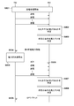
- FIG. 13 shows a sequence for performing power transmission.
- the phase before power transmission includes the Selection phase (S1301), Ping phase (S1302), Identity and Configuration phase (S1303), Negotiation phase (S1304), and Calibration phase (S1305) after RX1 is mounted on TX2. sell.
- the Identity and Configuration phase will be referred to as the I & C phase.
- the TX2 intermittently transmits the Analog Ping, and the object is placed on the charging stand 3 of the TX2 (for example, the RX1, the conductor piece, etc. are placed on the charging stand 3). Is detected. TX2 detects at least one of the voltage value and the current value of the power transmission antenna when the Analog Ping is transmitted, and determines that an object exists when the voltage value falls below a certain threshold value or when the current value exceeds a certain threshold value. Then, the transition to the Ping phase occurs.
- TX2 transmits a Digital Ping that has a larger power than the Analog Ping.
- the size of the Digital Ping is sufficient power to activate the control unit of the RX1 mounted on the TX2.
- RX1 notifies TX2 of the magnitude of the received voltage.
- the TX2 recognizes that the object detected in the Selection phase is the RX1 by receiving the response from the RX1 that has received the Digital Ping.
- the TX2 Upon receiving the notification of the received voltage value, the TX2 transitions to the I & C phase. Further, the TX2 may measure the Q-Factor of the power transmission antenna (power transmission coil) before transmitting the Digital Ping. This measurement result is used when executing the foreign matter detection process (second foreign matter detection) using the Q value measurement method (Quality Factor method).
- TX2 identifies RX1 and acquires device configuration information (capacity information) from RX1. Therefore, RX1 transmits the ID Packet and the Configuration Packet to TX2.
- the ID Packet contains the identifier information of RX1
- the Configuration Packet contains the device configuration information (capacity information) of RX1.
- the TX2 that has received the ID Packet and the Configuration Packet responds with an acknowledge (ACK, acknowledgment). Then, the I & C phase ends.
- the GP value is determined based on the value of the Guaranteed Power (hereinafter referred to as "GP") required by RX1 and the power transmission capacity of TX2. Further, the TX2 executes foreign matter detection (second foreign matter detection) using the Q value measurement method (Quality Factor method) in accordance with the request from RX1. Further, the WPC standard stipulates a method of once shifting to the Power Transfer phase and then performing the same processing as the Negotiation phase again at the request of RX1. The phase that shifts from the Power Transfer phase and performs these processes is called the Renegotiation phase.
- the above-mentioned CAL process is performed based on the WPC standard. Further, RX1 notifies TX2 of a predetermined received power value (received power value in light load state / received power value in maximum load state), and TX2 makes adjustments for efficient power transmission.
- the received power value notified to TX2 can be used for the foreign matter detection process (first foreign matter detection) by the Power Loss method.
- TX2 and RX1 use the same power transmission antenna (power transmission coil) and power reception antenna (power reception coil) used when performing wireless power transmission, and transmit from the power transmission antenna or power reception antenna. Communication is performed by superimposing a signal on the generated electromagnetic wave.
- the range in which communication between TX2 and RX1 is possible is almost the same as the range in which power transmission is possible in TX2. In one example, the communication between TX2 and RX1 is based on the WPC standard.
- the amount of power guaranteed when RX1 receives power from TX2 is defined by a value called GP.
- the GP guarantees the output to the load of RX1 (for example, charging circuit, battery, etc.) even if the positional relationship between RX1 and TX2 fluctuates and the power transmission efficiency between the power receiving antenna and the power transmission antenna decreases. Indicates the power value to be generated. For example, when the GP is 5 watts, even if the positional relationship between the power receiving antenna and the power transmitting antenna fluctuates and the power transmission efficiency decreases, the TX2 controls the power transmission so that it can output 5 watts to the load in the RX1. I do.
- the WPC standard stipulates a method for the TX2 to detect the presence of an object (foreign matter) that is not a power receiving device (near the power receiving antenna) around the TX2.
- the Power Loss method first foreign matter detection
- the Q value measurement method second foreign matter detection
- Foreign matter detection by the Power Loss method is performed during the power transmission (transmission) (described later in the Power Transfer phase) based on the above-mentioned CAL processing and the data.
- the foreign matter detection by the Q value measurement method is executed before the power transmission (before the digital ping transmission described later, the negotiation phase or the negotiation phase).
- TX2 repeatedly intermittently transmits the WPC standard Analog Ping in order to detect an object existing within the power transmission range (S401).
- the TX2 executes the processes defined as the Selection phase and the Ping phase of the WPC standard, and waits for the RX1 to be mounted.
- RX1 brings RX1 closer to TX2 in order to charge RX1 (for example, a smartphone) (S402).
- RX1 for example, a smartphone
- S402 a method of loading RX1 on TX2 can be considered.
- the TX2 detects that an object exists within the power transmission range (S403, S404), it transmits a WPC standard Digital Ping (S405).
- the RX1 receives the Digital Ping, it can grasp that the TX2 has detected the RX1 (S406). Further, TX2 determines that the detected object is RX1 and RX1 is placed on the charging stand 3 when there is a predetermined response to Digital Ping.
- the TX2 When the TX2 detects the placement of the RX1, it acquires the identification information and the capability information from the RX1 by the communication of the I & C phase defined by the WPC standard (S407).
- the identification information of RX1 includes the Manufacturer Code and the Basic Device ID.
- the capability information of RX1 includes information that can specify the version of the corresponding WPC standard, a value indicating the maximum power that RX1 can receive (Maximum Power Value), and whether or not it has a negotiation function of the WPC standard. Information indicating that is included.
- the TX2 may acquire the identification information and the capability information of the RX1 by a method other than the communication of the I & C phase of the WPC standard.
- the identification information may be any other identification information that can identify an individual RX1 such as Wireless Power ID. Information other than the above may be included as the ability information.
- TX2 determines the values of RX1 and GP by the communication of the Negotiation phase defined by the WPC standard (S408).
- S408 not only the communication in the Negotiation phase of the WPC standard but also other procedures for determining the GP may be executed.
- TX2 After determining the GP, TX2 performs the above-mentioned CAL process based on the GP.
- the RX1 transmits information including the received power in the light load state (hereinafter referred to as the first received power information) to the TX2 (S409).
- the first received power information in the present embodiment is data corresponding to the received power of RX1 when the transmitted power of TX2 is 250 mW.
- the first received power information will be described as being a received power packet (RP packet) including a Received Power (mode 1) defined by the WPC standard, but other messages may be used.
- the TX2 determines whether or not to accept the first received power information based on the power transmission state of the TX2.
- the TX2 when the TX2 receives the first received power information including the data corresponding to the received power exceeding the transmitted power, it may determine that it does not accept the first received power information. Alternatively, TX2 may determine that it does not accept the first received power information when the ratio of the received power to the transmitted power is less than the threshold value.
- the TX2 transmits an acknowledgment (ACK) when accepting the first received power information, and a negative response (NAK) when not accepting the first received power information (S410).
- ACK acknowledgment
- NAK negative response
- the RX1 determines whether it is possible to receive a larger amount of power, and if possible, positively to increase the transmitted power from the TX2.
- the power transmission output change instruction including the value of is transmitted (S411).
- the TX2 receives the above-mentioned power transmission output change instruction, responds with an ACK when the transmission power can be increased, and increases the transmission power (S412, S413). Since the GP is set to 5W in S408, the transmission of the transmission output change request (+) such as S411 and S414 is repeated until the transmission power becomes 5W.
- TX2 When TX2 receives a power increase request exceeding GP from RX1 (S414), it suppresses power transmission beyond the specified value by responding to NAK in response to the power transmission output change instruction (S415).
- the RX1 determines that the predetermined received power has been reached by receiving the NAK from the TX2, the RX1 transmits data including the received power in the load connected state to the TX2 as the second received power information (S417).
- the second received power information is the received power information of RX1 when the transmitted power of TX2 is 5 watts.
- the second received power information is a received power packet including a Received Power (mode 2) defined by the WPC standard, but other messages may be used.
- TX2 calculates the power loss between TX2 and RX1 based on the received power value included in the first and second received power information and the transmitted power value corresponding to each of the first and second received power information. (S416). By interpolating these power losses, it is possible to calculate the power loss value between TX2 and RX1 at the time of transmission power of all TX2 (in this case, TX2 transmission power is 250 mW to 5 W).
- TX2 transmits an ACK to the second received power information from RX1 (S418), completes the calibration phase, and shifts to the Power Transfer phase.
- the TX2, which has determined that the charging process can be started starts the power transmission process for the RX1 and starts charging the RX1.
- TX2 and RX1 perform device authentication processing (S419), and if it is found that each device can support a larger GP, the GP may be reset to a larger value, here 15W. Good (S420).
- RX1 and TX2 change the power transmission output by using the power transmission output change instruction, ACK, and NAK in order to increase the power transmission power of TX2 to 15W (S421 to S424, S508).
- the RX1 transmits a received power packet (hereinafter referred to as a third received power information) including data corresponding to the received power in the load connection state of the RX1 when the transmitted power of the TX2 is 15 W (hereinafter referred to as the third received power information). S425).
- TX2 calculates the power loss between TX2 and RX1 based on the received power value included in the first, second and third received power information and the corresponding transmitted power value (S426). This makes it possible to estimate the power loss at the time of transmission power of all TX2 (in this case, TX2 transmission power is 250 mW to 15 W).
- TX2 creates a calibration point using the third received power from the RX1, it transmits an ACK to the RX1 (S427) and completes the CAL process.
- TX2 which has determined that the charging process can be started, starts the power transmission process for RX1 (S428).
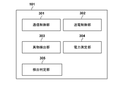
- FIG. 1 is a functional block diagram showing a configuration example of TX2 according to the present embodiment.
- TX2 has a control unit 101, a power supply unit 102, a power transmission unit 103, a communication unit 104, a power transmission antenna 105, a memory 106, and an antenna switching unit 107.
- the control unit 101, the power supply unit 102, the power transmission unit 103, the communication unit 104, the memory 106, and the antenna switching unit 107 are described as separate bodies, but any plurality of functional blocks among them are the same chip. It may be implemented in.
- the control unit 101 controls the entire TX2 by executing a control program stored in the memory 106, for example.
- the control unit 101 controls power transmission control including communication for device authentication in TX2.
- the control unit 101 may perform control for executing an application other than wireless power transmission.
- the control unit 101 includes one or more processors such as a CPU (central processor unit) or an MPU (microprocessor unit), for example.
- the control unit 101 may be configured with hardware dedicated to specific processing such as an integrated circuit (ASIC) for a specific application.
- the control unit 101 may be configured to include an array circuit such as an FPGA (Field Programmable Gate Array) compiled to execute a predetermined process.
- the control unit 101 stores information to be stored in the memory 106 during execution of various processes. Further, the control unit 101 can measure the time using a timer (not shown).
- the power supply unit 102 supplies power to each functional block.
- the power supply unit 102 is, for example, a commercial power supply or a battery.
- the battery stores electric power supplied from a commercial power source.
- the power transmission unit 103 converts the DC or AC power input from the power supply unit 102 into AC frequency power in the frequency band used for wireless power transmission, and inputs the AC frequency power to the power transmission antenna 105 to receive power to the RX1. Generates an electromagnetic wave to make it.
- the power transmission unit 103 converts the DC voltage supplied by the power supply unit 102 into an AC voltage by a switching circuit having a half-bridge or full-bridge configuration using an FET (Field Effect Transistor).
- the power transmission unit 103 includes a gate driver that controls ON / OFF of the FET.
- the power transmission unit 103 controls the strength of the electric power of the electromagnetic wave to be output by adjusting the voltage (transmission voltage) and / or current (transmission current) input to the power transmission antenna 105. Increasing the transmission voltage or transmission current increases the strength of the electromagnetic power, and decreasing the transmission voltage or transmission current reduces the intensity of the electromagnetic power. Further, the power transmission unit 103 controls the output of the AC frequency power so that the power transmission from the power transmission antenna 105 is started or stopped based on the instruction of the control unit 101. Further, it is assumed that the power transmission unit 103 has an ability to supply electric power sufficient to output 15 watts (W) of electric power to the charging unit 206 (FIG. 2) of RX1 corresponding to the WPC standard.
- W watts
- the communication unit 104 communicates with the RX1 for power transmission control based on the WPC standard as described above.
- the communication unit 104 modulates the electromagnetic wave transmitted from the power transmission antenna 105, transmits information to the RX1, and performs communication. Further, the communication unit 104 demodulates the electromagnetic wave transmitted from the power transmission antenna 105 modulated by the RX1 and acquires the information transmitted by the RX1. That is, the communication performed by the communication unit 104 is performed by superimposing the signal on the electromagnetic wave transmitted from the power transmission antenna 105. Further, the communication unit 104 may communicate with the RX1 by communication according to a standard different from the WPC standard using an antenna different from the power transmission antenna 105, or may selectively use a plurality of communications to communicate with the RX1. You may.
- the memory 106 can also store the states of TX2 and RX1 (transmitted power value, received power value, etc.).
- the state of TX2 can be acquired by the control unit 101
- the state of RX1 can be acquired by the control unit 201 (FIG. 2) of RX1, and can be received via the communication unit 104.
- the power transmission antenna 105 has a plurality of antennas (coils).
- the antenna switching unit 107 selects and switches any one of the plurality of antennas (coils).
- the power transmission antenna 105 may have one power transmission antenna 105 instead of a plurality of antennas. In that case, the antenna switching unit 107 is not required.
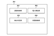
- FIG. 2 is a block diagram showing a configuration example of RX1 according to the present embodiment.
- RX1 includes a control unit 201, a UI (user interface) unit 202, a power receiving unit 203, a communication unit 204, a power receiving antenna 205, a charging unit 206, a battery 207, a memory 208, and a switch unit 209.
- the plurality of functional blocks shown in FIG. 2 may be realized as one hardware module.
- the control unit 201 controls the entire RX1 by executing a control program stored in the memory 208, for example. That is, the control unit 201 controls each functional unit shown in FIG. 3B. Further, the control unit 201 may perform control for executing an application other than wireless power transmission.
- An example of the control unit 201 includes one or more processors such as a CPU or an MPU.
- the entire RX1 (if the RX1 is a smartphone, the entire smartphone) may be controlled in cooperation with the OS (Operating System) executed by the control unit 201.
- control unit 201 may be configured with hardware dedicated to a specific process such as an ASIC. Further, the control unit 201 may be configured to include an array circuit such as an FPGA compiled to execute a predetermined process. The control unit 201 stores in the memory 208 information to be stored during execution of various processes. Further, the control unit 201 can measure the time using a timer (not shown).
- the UI unit 202 outputs various outputs to the user.
- the various outputs referred to here are operations such as screen display, LED blinking and color change, audio output by a speaker, and vibration of the RX1 main body.
- the UI unit 202 is realized by a liquid crystal panel, a speaker, a vibration motor, and the like.
- the power receiving unit 203 acquires AC power (AC voltage and AC current) generated by electromagnetic induction generated by electromagnetic waves radiated from the transmission antenna 105 of TX2 in the power receiving antenna 205. Then, the power receiving unit 203 converts the AC power into direct current or AC power having a predetermined frequency, and outputs the power to the charging unit 206 that performs processing for charging the battery 207. That is, the power receiving unit 203 supplies electric power to the load in RX1.
- the GP described above is electric power that is guaranteed to be output from the power receiving unit 203. It is assumed that the power receiving unit 203 has an ability to supply electric power for charging the battery 207 by the charging unit 206 and to supply electric power sufficient to output 15 watts of electric power to the charging unit 206.
- the switch unit 209 is for controlling whether or not to supply the received electric power to the battery (load).
- the switch unit 209 connects the charging unit 206 and the battery 207, the electric power received via the power receiving antenna 205 is supplied to the battery 207. That is, the switch unit 209 is a switching unit that switches whether or not to disconnect the power receiving antenna 205 and the battery 207, which is a load. If the switch unit 209 disconnects the charging unit 206 and the battery 207 with the switch, the received power is not supplied to the battery 207.
- the switch unit 209 is arranged between the charging unit 206 and the battery 207 in FIG. 2, the switch unit 209 may be arranged between the power receiving unit 203 and the charging unit 206.
- the switch unit 209 is described as one block in FIG. 2, the switch unit 209 can be realized as a part of the charging unit 206.
- the communication unit 204 communicates with the communication unit 104 of the TX2 for power reception control based on the WPC standard as described above.
- the communication unit 204 demodulates the electromagnetic wave input from the power receiving antenna 205 and acquires the information transmitted from the TX2. Then, the communication unit 204 communicates with the TX2 by superimposing the signal related to the information to be transmitted to the TX2 on the electromagnetic wave by load-modulating the input electromagnetic wave.
- the communication unit 204 may communicate with the TX2 by a standard different from the WPC standard using an antenna different from the power receiving antenna 205, or may selectively use a plurality of communications to communicate with the TX2. May be good.
- the memory 208 stores the states of TX2 and RX1 in addition to storing the control program.
- the state of RX1 can be acquired by the control unit 201
- the state of TX2 can be acquired by the control unit 101 of TX2, and can be received via the communication unit 204.
- the control unit 101 includes a communication control unit 301, a power transmission control unit 302, a foreign matter detection unit 303, a power measurement unit 304, and a detection determination unit 305.
- the communication control unit 301 performs control communication with the RX1 based on the WPC standard via the communication unit 104. For example, the communication control unit 301 receives a received power packet including data indicating the received power from RX1 to RX1 and transmits a response to the received power packet.
- the power transmission control unit 302 controls the power transmission unit 103 and controls the power transmission to the RX1.
- the foreign matter detection unit 303 performs the first foreign matter detection based on the power loss between the power transmission device and the power receiving device, and the second foreign matter detection by measuring the Q value of the power transmission antenna 105.
- the foreign matter detection unit 303 will be described as performing foreign matter detection by the Q value measurement method as the second foreign matter detection, but the foreign matter detection process may be performed by using another method.
- foreign matter may be detected by using the counter device detection function according to the NFC standard.
- the foreign matter detecting unit 303 can also detect that the state on the TX2 has changed as a function other than detecting the foreign matter. For example, an increase or decrease in the number of RX1 on TX2 may be detected. Alternatively, it may be detected that RX1 on TX2 has moved.
- the power measurement unit 304 measures the power output to the RX1 via the power transmission unit 103, and calculates the average output power value for each unit time.
- the foreign matter detection unit 303 performs the foreign matter detection process by the Power Loss method based on the measurement result by the power measurement unit 304 and the received power information received from the power receiving device via the communication control unit 301.
- the detection determination unit 305 determines whether or not to execute the foreign matter detection based on at least one of the information received from the RX1 and the power measured by the power measurement unit 304. Further, the detection determination unit 305 may determine at least one of the foreign matter detections (at least one of the first foreign matter detection and the second foreign matter detection).
- the functions of the communication control unit 301, the power transmission control unit 302, the foreign matter detection unit 303, the power measurement unit 304, and the foreign matter detection determination unit 305 are realized as programs that operate in the control unit 101.
- Each processing unit is configured as an independent program, and can operate in parallel while synchronizing the programs by event processing or the like.
- the control unit 201 includes a communication control unit 351, a power measurement unit 352, a detection determination unit 353, and a power reception control unit 354.
- the communication control unit 351 performs control communication with the TX2 via the communication unit 204.
- the power measurement unit 352 measures the power received from the TX2, and the communication control unit 351 transmits data indicating the received power to the TX2.
- the detection determination unit 353 determines at least one of whether the TX2 needs to execute the foreign matter detection and at least one of the first foreign matter detection and the second foreign matter detection, and causes the communication control unit 351 to perform the communication control unit 351.
- a signal for causing TX2 to perform foreign matter detection is transmitted via the signal.
- the power receiving control unit 354 controls the power receiving unit 203 and controls the power transmission with the TX2. Further, the power receiving control unit 354 controls the communication unit 204 and controls the phase and parameters of the power transmission.
- the functions of the communication control unit 351, the power measurement unit 352, the detection determination unit 353, and the power reception control unit 354 are realized as programs that operate in the control unit 201.
- Each processing unit is configured as an independent program, and can operate in parallel while synchronizing the programs by event processing or the like.
- Power Transfer Phase Processing Example> Power is transmitted from TX2 to RX1. Further, the foreign matter is detected by the first foreign matter detection.
- the power loss power loss in the normal state
- the TX2 determines that there is a foreign substance when the power loss between the TX2 and the RX1 calculated during the subsequent power transmission exceeds the threshold value from the reference power loss in the normal state.
- the CAL process is executed in a state where there is no foreign matter even though there is actually a foreign matter between the power transmission device and the power receiving device.
- the presence or absence of the foreign matter is determined based on the power loss in the state where the foreign matter is present, and the foreign matter detection accuracy is lowered. Therefore, in the present embodiment, the CAL process is performed even though the foreign substance exists between the TX2 and the RX1, and the process for preventing the foreign matter detection accuracy by the Power Loss method from being lowered will be described.
- the CAL process for acquiring the data necessary for the first foreign matter detection is executed.
- RX1 controls TX2 to check whether foreign matter is mixed in the power transmission device by using the second foreign matter detecting method. This makes it possible to perform the CAL process in an appropriate state (without foreign matter).
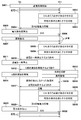
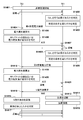
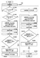
- the operations of TX2 and RX1 for realizing this will be described with reference to the sequence of FIG. 5, the flowchart of the power receiving device of FIG. 6, and the flowchart of the power transmission device of FIG.
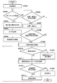
- RX1 determines whether or not it is necessary to perform CAL processing after starting power reception (S501, S601, S701) (S502, S602). For example, when changing the transmitted power to a higher power, it is necessary to create a new calibration point (for example, 1100, 1103, 1101 in FIG. 11), so it is determined that the CAL process needs to be executed. do.
- the temperature of TX2 or RX1 may rise due to power transmission from TX2 to RX1, and the characteristics of the circuits and components of TX2 or RX1 may fluctuate.
- RX1 executes CAL processing in order to update the calibration points. It can be determined that it is necessary to do so. That is, the RX1 may include a temperature sensor (not shown) and may determine whether or not it is necessary to execute the CAL process based on the value of the temperature sensor. In this case, it may be determined that the CAL process needs to be executed when the value of the temperature sensor changes by a predetermined value or more from the value when the CAL process was executed last time. Alternatively, the RX1 is provided with a timer (not shown) to determine whether or not it is necessary to execute the CAL process according to the lapse of time since the start of power reception or the lapse of time since the previous CAL process was executed. You may.
- RX1 determines whether or not a predetermined condition is satisfied (S503, S603). This determines whether or not there is a high possibility that a foreign substance is mixed between TX2 and RX1 (whether or not a predetermined condition is satisfied). For example, when a predetermined time has elapsed since the previous foreign matter detection executed by the foreign matter detection unit 303 shown in FIG. 3A, the RX1 has a foreign matter mixed between the TX2 and the RX1. Judge that the possibility is high. On the other hand, if the predetermined time has not elapsed, the RX1 determines that it is unlikely that a foreign substance is mixed between the TX2 and the RX1.
- RX1 converts the received power value (fourth received power information) of the received power received by RX1 into TX2 in the received power packet (RP packet). Transmit (S504, S604, S702).
- the TX2 that has received the RP packet determines whether or not the RP packet indicates the execution of the CAL process (S703). In one example, the TX2 has the RP packet executing the CAL processing based on the presence / absence of the execution instruction of the CAL processing or the execution instruction of the first foreign matter detection included in the RP packet or in a signal different from the RP packet. It is determined whether or not it indicates.
- the TX2 creates a calibration point based on the received fourth received power information and the corresponding transmitted power (S505, S704), and transmits an ACK to the TX2 (S506, S705).
- TX2 determines that the RP packet is an execution instruction for detecting the first foreign matter
- TX2 executes the first foreign matter detection (S706), and when a foreign matter is detected (Yes in S707), RX1 indicates that fact. (S709) and stop power transmission (S710). If it is determined that no foreign matter is detected in the first foreign matter detection in S706 (No in S707), RX1 is notified to that effect (S708), and the process is returned to S702.
- RX1 determines whether or not it is necessary to perform the CAL process again after the elapse of a predetermined time after S604 (S502, S607), and determines whether or not the predetermined condition is satisfied (S503, S608). This determines whether or not there is a high possibility that foreign matter is mixed between the power transmitting device and the power receiving device. For example, if a predetermined time has elapsed since the last CAL treatment was executed, it is determined that there is a high possibility of foreign matter contamination, and before the CAL treatment is performed, the power transmission device uses a foreign matter detection method different from the first foreign matter detection method. Is used to check if foreign matter is mixed between TX2 and RX1.
- the RX1 transmits, for example, an EPT packet (End Power Transfer packet) to the TX2 in order to cause the TX2 to execute a foreign matter detection method different from that of the first foreign matter detection (S505, S609, S711).
- EPT packet End Power Transfer packet
- TX2 ends the Power Transfer phase and shifts to the Selection phase (S712). That is, it is reset to the state before power transmission is performed.
- the foreign matter detection (second foreign matter detection) by the Q value measurement method, which is executed in the Negotiation phase or the Negotiation phase, is executed. In this way, it is possible to perform the second foreign matter detection different from the first foreign matter detection before executing the CAL process. As a result, the possibility that foreign matter is mixed between TX2 and RX1 when the CAL process is executed is reduced, and the first foreign matter detection can be performed with higher accuracy.
- the RX1 transmits an EPT (End Power Transfer) packet to the TX2 in order to execute the second foreign matter detection, but the EPT packet is used to execute the second foreign matter detection.
- EPT End Power Transfer
- Signals other than may be used.
- the RX1 may send a signal instructing the TX2 to transition to the Regency phase.
- RX1 may instruct TX2 to transition to the Selection phase so as not to change the reference value for detecting the second foreign matter.
- the RX determines whether or not the predetermined condition for executing the second foreign matter detection is satisfied before executing the CAL process for detecting the first foreign matter. Further, when it is determined that the predetermined condition is satisfied, the TX is controlled so as to execute the second foreign matter detection. As a result, the possibility of executing the CAL process for detecting the first foreign matter is reduced in a state where there is a high possibility that a foreign matter is present between TX2 and RX1, and the detection accuracy of the foreign matter by the first foreign matter detection is lowered. You can prevent that.
- ⁇ Second embodiment> In the first embodiment, if it is determined that the second foreign matter detection is to be executed before the CAL process for detecting the first foreign matter is executed, the power transmission device is configured to perform the second foreign matter detection by ending the Power Transfer phase. The method of control was described. In the second embodiment, when it is determined that the CAL process required for executing the first foreign matter detection is necessary, the power transmission device is controlled so as to execute the second foreign matter detection within a shorter time. Will be described. The description of the same configuration, function, and processing as in the first embodiment will be omitted.
- the first foreign matter detection requires a CAL process, but before executing the CAL process, the RX1 checks whether the TX2 uses the second foreign matter detection method to check whether foreign matter is mixed in the power transmission device. To control.
- the second foreign matter detection is also performed during the Power Transfer phase, so that whether or not the foreign matter is present on the power transmission device in a shorter time than in the first embodiment. It becomes possible to check whether or not.
- TX2 and RX1 to realize this will be described with reference to the sequence of FIG. 8, the flowchart of the power receiving device of FIG. 9, and the flowchart of the power transmission device of FIG.
- TX2 starts power transmission to RX1, and RX1 starts power reception (S801, S901, S1001).
- RX1 determines whether or not it is necessary to perform CAL processing after starting power reception (S802, S902). For example, when the transmitted power is changed to a higher power, it is necessary to create a new calibration point (for example, 1100, 1103, 1101 in FIG. 11), and therefore it is necessary to perform CAL processing. Is determined.
- power transmission causes the temperature of TX2 or RX1 to rise, causing fluctuations in the characteristics of the circuits and components of TX2 or RX1, and the line or curve connecting the calibration points (for example, the line connecting 1100, 1103, 1101 in FIG. 11). ) May fluctuate. In this case, since it is necessary to update the calibration point, it is determined that the CAL process needs to be performed.
- a predetermined condition for executing the second foreign matter detection is satisfied (S803, S903). This determines whether there is a high possibility that a foreign substance is present between TX2 and RX1. For example, when a predetermined time has passed since the previous foreign matter detection performed by the foreign matter detecting unit 303 shown in FIG. 3A, it is determined that there is a high possibility that a foreign matter is mixed between TX2 and RX1, and the predetermined amount is determined. If the time has not passed, it is judged that there is a low possibility that foreign matter is mixed.
- the RX1 converts the data (fourth received power information) corresponding to the received power received by the RX1 into the TX2 in the received power packet (RP packet). Transmit (S804, S904).
- the TX2 receives the RP packet (S1002), it executes the CAL process (S805, S1003), and if there is no problem as a result of the CAL process, transmits an ACK to the TX2 (S806, S1004). Then, based on the result of the CAL processing, the TX2 detects the foreign matter at a predetermined timing during power transmission by the first foreign matter detection (S807, S1005).
- RX1 determines whether or not it is necessary to perform the CAL process again (S808, S902), and determines whether or not a predetermined condition is satisfied (S903, S809). This determines whether or not there is a high possibility that a foreign substance is present between TX2 and RX1. In this case, if the elapsed time exceeds a predetermined time, it is determined that there is a high possibility of foreign matter contamination, and before performing the CAL treatment, TX2 uses a foreign matter detection method different from the Power Loss method, and uses a foreign matter detection method different from that of TX2. Confirm that no foreign matter is mixed with RX1.
- RX1 instructs TX2 to suspend power transmission (S905, S810).
- the TX2 receives the instruction to suspend the power transmission (S1006)
- the TX2 suspends the power transmission (S1007, S811).
- RX1 requests TX2 to perform foreign matter detection (second foreign matter detection) by the Q value measuring method (S906, S812).
- RX1 controls the switch unit 209 to disconnect the load (battery or the like) (S907, S813). This is because, when the second foreign matter is detected, if the load of RX1 is in the connected state, the foreign matter cannot be detected or the accuracy of the foreign matter detection is lowered.
- the TX2 receives the execution instruction of the foreign matter detection by the Q value measurement method (Q-FACTOR MEASUREMENT) (S1008, S812)
- the TX2 performs the foreign matter detection by the Q value measurement method (Q-FACTOR MEASUREMENT) (S1009, S814).
- RX1 connects the load after a predetermined time has elapsed for TX2 to detect foreign matter by the Q value measurement method (Q-FACTOR MEASUREMENT) (S908, S815). If TX2 does not detect a foreign matter as a result of the second foreign matter detection (No in S1010), TX2 notifies RX1 that no foreign matter has been detected (S1011, S816).
- the RX1 When the RX1 receives a notification from the TX2 that the TX2 has not detected a foreign substance (No in S909), the RX1 instructs the TX2 to restart the power transmission (S910, S817), and the TX2 instructs the power transmission to resume. (S1012), power transmission is restarted (S1013).
- RX1 returns the processing to S902, determines whether or not to perform CAL processing (S902, S818), and sets a predetermined condition. It is determined whether or not the condition is satisfied (S903, S819).
- RX1 When it is determined that RX1 satisfies a predetermined condition, it is determined to perform CAL processing, and RX1 transmits data (fifth power received power information) for executing CAL processing to TX2 by RP (S904, S820).
- RP RP
- the TX2 receives the RP (S1002, S820), it calculates the power loss, executes the CAL process (S1003, S821), and transmits an ACK to the RX1 (S1004, S822).
- the TX2 detects a foreign matter in S1010, it notifies RX1 that the foreign matter has been detected (S1015) and stops power transmission (S1016).
- the RX1 When the RX1 receives a notification from the power transmission device that a foreign substance has been detected (Yes in S909), the RX1 may transmit an EPT packet to the TX2 (S911) to stop the power transmission.
- the RX1 may transmit an EPT packet to the TX2 (S911) to stop the power transmission.
- a pause packet requesting a temporary stop (instantaneous interruption) of power transmission is transmitted to the power transmission device, and before the CAL processing required for foreign matter detection is performed, the foreign matter is detected.
- the method of controlling the power transmission device so as to perform the Q value measurement method was described.
- the second foreign matter detection is controlled to be performed during the Power Transfer phase without adding a new packet (protocol) to the existing WPC standard, and the foreign matter is mixed into the power transmission device in a shorter time. Describes how to check if it is. As a result, compatibility can be ensured while reducing the verification required by adding a new packet (protocol).
- the description of the configuration, function, or process similar to that of the first or second embodiment will be omitted.
- TX2 starts power transmission to RX1, and RX1 starts power reception (S1501, S1601, S1401).
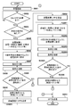
- the RX1 determines whether or not it is necessary to execute the CAL process after starting the power reception (S1502, S1402). For example, when the transmitted power is changed to a higher power, it is necessary to create a new calibration point (for example, 1100, 1103, 1101 in FIG. 11), so that it is necessary to execute the CAL process. Judge that there is.
- the temperature of TX2 or RX1 rises and the characteristics of circuits and parts fluctuate, causing fluctuations in the lines connecting calibration points or curves (for example, the lines connecting 1100, 1103, 1101 in FIG. 11). May occur.
- RX1 determines that it is necessary to perform a CAL process in order to update the calibration point.
- RX1 determines whether or not a predetermined condition for executing the second foreign matter detection is satisfied (S1503, S1403). This determines whether or not there is a high possibility that a foreign substance is mixed between TX2 and RX1. For example, if a predetermined time has not passed since the previous foreign matter detection (first or second foreign matter detection) performed by the foreign matter detection unit 303 shown in FIG. 3A, the RX1 has a foreign matter between TX2 and RX1. It is judged that the possibility of contamination is low. Then, when a predetermined time or more has passed since the previous detection of the foreign matter, the RX1 determines that there is a high possibility that the foreign matter is mixed between the TX2 and the RX1.
- RX1 transmits the received power value (fourth received power information) of the received power received by RX1 to TX2 by RP (S1504, S1404).
- the TX2 receives the RP (S1602) and executes the CAL process (S1603, S1405). Then, TX2 determines whether or not the received power value in the received Received Power Packet and the calculated power loss value are appropriate (S1604, S1506). This is determined based on, for example, whether or not the received power value in the received RP is larger than a predetermined threshold value, whether or not the calculated power loss value value is larger than a predetermined threshold value, and the like.
- the TX2 determines that there is no problem with the received power value in the received RP, the TX2 transmits an ACK to the RX1 (S1605, S1507). Then, TX2 detects the first foreign matter based on the Power Loss method, which is the first foreign matter detecting method, at a predetermined timing during power transmission (S1606, S1422). After a predetermined time, RX1 again determines whether the CAL process needs to be performed (S1502, S1408). When it is determined that the CAL process needs to be performed, it is then determined whether or not a predetermined condition is satisfied (S1503, S1409).
- RX1 transmits a signal for causing TX2 to execute the second foreign matter detection.
- the RP packet is transmitted to the TX2 with a value that determines that the TX2 is not appropriate, rather than the received power value of the received power received by the RX1, as the received power value (S1505, S1410).
- This value may be, for example, the maximum value or the minimum value of the received power value that can be set in the RP packet. Alternatively, it may be a predetermined value for causing TX2 to detect the second foreign matter.
- the TX2 may be made to perform the second foreign matter detection by transmitting the RP packet to the TX2 a plurality of times in succession within a predetermined time.
- TX2 performs CAL processing (power loss value calculation) based on the information included in the received RP (S1603, S1411). Then, TX2 determines whether or not the received power value in the received RP or the calculated power loss value is appropriate (S1604, S1412). At this time, as described above, when the RX1 transmits the RP with a value that determines that the TX2 is not appropriate as the received power value, the TX2 is the received power value in the RP or the calculated power loss value. It will be determined that the value of is not appropriate.
- the RX1 transmits a value that is clearly abnormal as a received power value to the TX2 by RP, so that the TX2 can recognize that the RX1 requests the execution of the second foreign matter detection. ..
- the TX2 requests the RX1 to execute the second foreign matter detection. It becomes possible to recognize that.
- the RX1 holds the information for requesting the TX2 to execute the second foreign matter detection at the place where the RX1 holds the information other than the received power value in the RP, so that the RX1 detects the second foreign matter.
- TX2 transmits the NAK for the received RP to RX1 (S1607, S1413).
- RX1 can recognize that TX2 is trying to detect the second foreign matter by the Q value measurement method (Q-FACTOR MEASUREMENT).
- RX1 recognizes that TX2 is about to detect the second foreign matter, and controls the switch unit 209 to disconnect the load (battery, etc.) (S1506, S1414). This is because when the foreign matter is detected by the Q value measurement method (Q-FACTOR MEASUREMENT), if the load of RX1 is in the connected state, the foreign matter detection by the Q value measurement method cannot be performed, or the accuracy of foreign matter detection is lowered. Because. Therefore, when TX2 detects a foreign matter that does not require disconnection of the load other than the Q value measurement method, the processing of S1414 is not necessary.
- Q-FACTOR MEASUREMENT Q-FACTOR MEASUREMENT
- TX2 performs foreign matter detection by the Q value measurement method (Q-FACTOR MEASUREMENT), which is the second foreign matter detection method (S1608, S1415). Then, the RX1 waits for a predetermined time for the TX2 to execute the foreign matter detection by the Q value measurement method (Q-FACTOR MEASUREMENT), and then controls the switch unit 209 to reconnect the load (battery or the like) (S1507). , S1416). Then, TX2 determines whether or not the foreign matter is detected as a result of detecting the foreign matter by the Q value measuring method (S1609, S1417). If the TX2 does not detect a foreign substance, it starts power transmission.
- Q-FACTOR MEASUREMENT the Q value measurement method
- S1608, S1415 the second foreign matter detection method
- the RX1 waits for a predetermined time for the TX2 to execute the foreign matter detection by the Q value measurement method (Q-FACTOR MEASUREMENT), and then controls the switch unit 209
- TX2 may notify RX1 that no foreign matter has been detected.
- the RX1 determines whether or not there is a notification that the foreign matter has been detected from the TX2 (S1507), determines that the foreign matter has not been detected if there is no notification for a predetermined time, and returns to S1502.
- the TX2 notifies that the foreign matter has not been detected, it may be determined that the foreign matter has not been detected and the process returns to S1502.
- TX2 detects a foreign substance in S1609
- TX2 notifies RX1 that the foreign substance has been detected (S1610).
- the RX1 may transmit an EPT to the TX2 (1509) to stop the power transmission.
- the RX1 determines that it is necessary to perform the CAL process in S1502 and the TX2 executes the second foreign matter detection and determines that no foreign matter exists
- the RX1 satisfies the predetermined condition in S1503 (the possibility of foreign matter contamination is high). It is judged to be low).
- the RP (fifth power received power information) is transmitted to the TX2 again in S1504 (S1504, S1418).
- the received power value of the received power received by RX1 is stored.
- the TX2 receives the RP (S1602, S1418), performs CAL processing based on the received RP (S1603, S1419), and the received power value in the received RP or the calculated power loss value is appropriate.
- the TX2 transmits an ACK to the RX1 (S1605, S1421). Then, TX2 transmits power to RX1 and executes first foreign matter detection at a predetermined timing based on the result of the above-mentioned CAL processing (S1606).
- TX2 determines in S1604 whether to perform the first foreign matter detection or the second foreign matter detection from the information of the RP from RX1. However, TX2 may determine which foreign matter is detected. That is, TX2 makes a determination in the same manner as in S1502 and S1503, transmits ACK when it is determined to execute the first foreign matter detection (S1605), and NAK when it is determined to execute the second foreign matter detection. May be transmitted (S1607).
- the second foreign matter detection is executed before the CAL processing is executed, and whether or not foreign matter is mixed in the power transmission device is shortened. It becomes possible to check by time.
- a method of confirming the presence or absence of foreign matter between TX2 and RX1 by a second foreign matter detection different from the first foreign matter detection before executing the CAL treatment used in the first foreign matter detection Said.
- the order in which the CAL treatment and the second foreign matter detection are performed is reversed, and after the CAL treatment for the first foreign matter detection is executed, the TX2 and RX1 are subjected to the second foreign matter detection different from the first foreign matter detection. You may check for foreign matter in between.
- the second foreign matter detection is executed after the CAL processing is executed, and when it is determined that there is a foreign matter between TX2 and RX1, the CAL processing is re-executed to obtain the result of the CAL processing in the state where the foreign matter is present. This is because it is possible to prevent the first foreign matter detection from being performed.
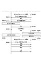
- TX2 and RX1 when the order of executing the CAL processing and the second foreign matter detection of the second embodiment according to the present embodiment is reversed is shown in the processing sequence diagram of RX1 and TX2 of FIG. 17 and FIG. It is shown in the flowchart of RX1.
- the processing of TX2 is the same as the flowchart of TX2 according to the second embodiment shown in FIG. Further, in the process sequence diagram of FIG. 17 and the flowchart of FIG. 18, the same reference numerals are used for the same processes as those of FIGS. 8 and 9, and the description thereof will be omitted.
- the RX1 determines that the predetermined condition for executing the second foreign matter detection is satisfied (Yes in S903), the RX1 transmits a Received Power Packet (RP) including the received power information for the CAL processing to the TX2 (S1801). , S820).
- the TX2 calculates the power loss value based on the received power information (fifth received power information) included in the RP and executes the CAL process (S821).
- RX1 performs a process of requesting TX2 to detect a second foreign matter (S906, S812), and when TX2 detects a foreign matter by detecting a second foreign matter (Yes in S909), an EPT is transmitted (S911). , The CAL process is executed again. As a result, it is possible to prevent the first foreign matter detection from being performed based on the reference power by the CAL process in the state where the foreign matter is present between the TX2 and the RX1.
- the CAL process is executed as soon as the TX2 receives the RP in S1801, but in one example, the execution of the CAL process may be waited for a predetermined time. For example, if the TX2 does not receive a power transmission suspension or a second foreign matter detection execution request from the RX1 within a predetermined time after receiving the RP, the received RP is used to execute the CAL process. You may. Then, when the TX2 receives the execution request for the temporary suspension of power transmission or the detection of the second foreign matter from the RX1, the CAL process may be executed after the detection of the second foreign matter.
- the TX2 calculates the power loss value and transmits the ACK before the detection of the second foreign matter, but the calibration point may be created after the detection of the second foreign matter. That is, the calibration point may be created after the processing of S1010 when the foreign matter is not detected by the second foreign matter detection (No in S1010).
- the RX1 that has received the notification from the TX2 that the foreign matter has been detected in the S909 may delete the calibration point created in the S1801 in the S911.
- TX2, which has transmitted a notification to RX1 that a foreign matter has been detected in S816 of FIG. 17, may be controlled so as not to detect the first foreign matter by using the area corresponding to the calibration point created in S821. good.
- the TX2 that detects a foreign substance in S816 transmits power with a transmission power larger than that of Pt3 until the CAL processing of Pt2 is re-executed. It does not have to be.
- TX2 does not have to perform the first foreign matter detection during power transmission with a power transmission power larger than Pt3.
- the order in which the CAL treatment and the second foreign matter detection of the second embodiment are performed is reversed, and after the CAL treatment for the first foreign matter detection is executed, the second foreign matter detection is different from the first foreign matter detection.
- the process of confirming the presence or absence of foreign matter between TX2 and RX1 by foreign matter detection has been described.
- the processing of TX2 and RX1 when the order of performing the CAL processing and the second foreign matter detection of the third embodiment are reversed will be described.
- TX2 and RX1 when the order of executing the CAL processing and the second foreign matter detection of the third embodiment according to the present embodiment is reversed is shown in the processing sequence diagram of RX1 and TX2 of FIG. 19 and FIG. It is shown in the flowchart of RX1.
- the processing of TX2 is the same as the flowchart of TX2 according to the third embodiment shown in FIG. Further, in FIGS. 19 and 20, the same processing as in FIGS. 14 and 15 of the third embodiment uses the same reference numerals, and the description thereof will be omitted.
- the RX1 determines that the predetermined condition for executing the second foreign matter detection is satisfied (Yes in S1503), the RX1 transmits a Received Power Packet (RP) including the received power information for the CAL processing to the TX2 (S2001). , S1418).
- the TX2 calculates the power loss value based on the received power information (fifth received power information) included in the RP and executes the CAL process (S1419). Further, the RX1 transmits an RP or a predetermined signal requesting the TX2 to detect a second foreign matter (S1505, S1410), and when the TX2 detects a foreign matter by the second foreign matter detection (Yes in S1508), the EPA is set.
- RP Received Power Packet
- the CAL process is executed as soon as the TX2 receives the RP in S1411, but in one example, the execution of the CAL process may be waited for a predetermined time. Since this is the same as the fourth embodiment, the description thereof will be omitted.
- the TX2 when the TX2 is configured to detect the second foreign matter when the received power packets are continuously received within a predetermined time, the received power packet is used. It is not necessary to include instructions to perform a second foreign object detection.
- the second foreign matter is different from the first foreign matter detection before and after instructing the execution of the CAL treatment used in the first foreign matter detection by combining the second embodiment and the fourth embodiment.
- the process of confirming the presence or absence of foreign matter between TX2 and RX1 by detection will be described.
- the third and fifth embodiments are combined, and before and after instructing the execution of the CAL process used in the first foreign matter detection, TX2 is detected by a second foreign matter different from the first foreign matter detection.
- TX2 is detected by a second foreign matter different from the first foreign matter detection. The process of confirming the presence or absence of foreign matter between the RX1 and the RX1 will be described.
- the first to seventh embodiments described above can be combined at will.
- the second embodiment and the third embodiment may be combined, and the power receiving device may be instructed to perform the second foreign matter detection by a different method depending on the model of the power transmission device, the version of the corresponding WPC standard, and the like. ..
- the Q value measurement method (Q-FACTOR MEASUREMENT) is mentioned as the second foreign matter detection different from the first foreign matter detection.
- a method of measuring the Q value of the transmission antenna (transmission coil) there is a method of transmitting a signal having a resonance frequency (for example, a sine wave, a square wave, etc.) for a predetermined time and measuring the Q value at the resonance frequency.
- a resonance frequency for example, a sine wave, a square wave, etc.
- a plurality of signals having at least a part of the frequency components of the plurality of frequencies to be measured are transmitted once, and the measurement results are subjected to arithmetic processing (for example, Fourier transform).
- arithmetic processing for example, Fourier transform
- the above-mentioned signal may be output, then the signal output may be stopped, and foreign matter detection may be performed based on the attenuation state of the signal waveform (electromagnetic wave waveform) (hereinafter referred to as waveform attenuation method). ..
- waveform attenuation method hereinafter referred to as waveform attenuation method.
- the ratio of the waveform amplitudes A1 and A2 is predetermined in the waveform attenuation state.
- the second foreign matter detection may be performed based on whether or not it is larger than the value.
- the second foreign matter may be detected based on the difference between the waveform amplitudes A1 and A2, the slope of the waveform attenuation (A1-A2) / (T2-T1), the time until the waveform becomes equal to or less than a predetermined amplitude, and the like.
- the Q value is based on the assumption that the frequency of the electromagnetic wave waveform is f.
- Q ⁇ f (T2-T1) / ln (A1 / A2) Since it is obtained from, foreign matter detection may be performed based on it.
- the sharpness of resonance (Q value) may be obtained from the above-mentioned measurement results at each frequency, and foreign matter may be detected based on this.
- the second foreign matter detection is performed between the TX2 and the RX1 so as not to execute the first foreign matter detection (foreign matter detection by the Power Loss method) using the calibration result in the state where the foreign matter exists between the TX2 and the RX1.
- a foreign matter detection method other than the Q value measurement method Q-FACTOR MEASUREMENT may be applied as the second foreign matter detection.
- the resonance frequency of the power transmission antenna in addition to the Q value of the power transmission antenna, the resonance frequency of the power transmission antenna, the sharpness of the resonance curve, or the inductor value, the coupling coefficient between the power transmission antenna and the object mounted on the power transmission device, and the power transmission antenna of the power transmission device are included.
- Measurement results such as the electrical characteristics of the power transmission unit may be used. Further, they may determine the presence or absence of foreign matter based on the measurement results of electrical characteristics at one frequency, or may determine the presence or absence of foreign matter based on the measurement results of electrical characteristics at a plurality of frequencies. ..
- a signal for example, a sine wave, a square wave, etc.
- the signal of each frequency is transmitted a plurality of times, and the signal of each frequency is used. This can be achieved by measuring the electrical characteristics.
- This method has the effect that the measurement can be performed with a relatively small amount of arithmetic processing in the power transmission device.
- a signal for example, a pulse wave
- arithmetic processing for example, Fourier transform
- electricity at a plurality of frequencies can be obtained by transmitting a signal having a part of a frequency component of a plurality of frequencies whose electrical characteristics are desired to be measured multiple times and performing arithmetic processing (for example, Fourier transform) on the measurement result. Characteristics can be calculated.
- This method has the effect that the measurement can be performed in a relatively short time because the number of times the signal for measurement is transmitted can be reduced.
- the second foreign matter detection method measurement results by sensors such as a photoelectric sensor, an eddy current displacement sensor, a contact displacement sensor, an ultrasonic sensor, an image discrimination sensor, and a weight sensor mounted on a power transmission device may be used. ..
- the TX2 and RX1 are subjected to the second foreign matter detection different from the first foreign matter detection.
- the method of confirming the presence or absence of foreign matter between the two is described.
- the presence or absence of foreign matter between TX2 and RX1 in the second foreign matter detection different from the first foreign matter detection described in the first to seventh embodiments is described.
- the same effect can be obtained by confirming. That is, by applying the first to seventh embodiments to the calibration process during the calibration phase, it is possible to reduce the possibility of foreign matter being mixed between the TX2 and the RX1 during the CAL process.
- the Power Loss method is mentioned as the first foreign matter detection.
- the calibration process (CAL process) has been described as estimating the power loss between the power transmission device and the power receiving device under different loads when there is no foreign matter between the power transmission device and the power receiving device.
- this calibration process is a step for acquiring parameters between the power receiving devices of the power transmitting device necessary for detecting foreign substances in a state where there is no foreign substance between the power transmitting device and the power receiving device. Therefore, foreign matter detection other than the Power Loss method may be applied as the first foreign matter detection.
- the detection of foreign matter by the above-mentioned Q value measurement method (Q-FACTOR MEASUREMENT) or the waveform attenuation method may be used as the first foreign matter detection. Then, in the calibration process, the Q value or the waveform attenuation state in the absence of foreign matter may be measured. Then, based on the result, the threshold value for detecting the first foreign matter and the like are determined, and the same effect can be obtained even if the foreign matter is detected.
- the present disclosure supplies a program that realizes one or more functions of the above-described embodiment to a system or device via a network or storage medium, and one or more processors in the computer of the system or device reads and executes the program. It can also be realized by the processing to be performed. It can also be realized by a circuit (for example, ASIC) that realizes one or more functions.
- a program that realizes one or more functions of the above-described embodiment to a system or device via a network or storage medium, and one or more processors in the computer of the system or device reads and executes the program. It can also be realized by the processing to be performed. It can also be realized by a circuit (for example, ASIC) that realizes one or more functions.
- ASIC application specific integrated circuit
Abstract
This power receiving device, capable of receiving power transmitted from a power transmission device capable of performing a first foreign object detection and a second foreign object detection, transmits, to the power transmission device, data that the power transmission device uses to perform the first foreign object detection, determines, before the transmission of the data, whether or not a predetermined condition for the power transmission device to perform the second foreign object detection different from the first foreign object detection is satisfied, and transmits, to the power transmission device, a signal for performing the second foreign object detection according to the determination.
Description
本開示は、受電装置および送電装置、ならびにそれらの制御方法およびプログラムに関する。
This disclosure relates to a power receiving device and a power transmitting device, and their control methods and programs.
近年、無線電力伝送システムの技術開発が広く行われている。特許文献1では、無線充電規格の標準化団体Wireless Power Consortiumが策定する規格(以下、Wireless Power Consortium規格(WPC規格)という)に準拠した送電装置および受電装置が開示されている。また、特許文献2には、WPC規格における、異物検出(Foreign Object Detection)が開示されている。
In recent years, technological development of wireless power transmission systems has been widely carried out. Patent Document 1 discloses a power transmitting device and a power receiving device conforming to a standard established by a wireless charging standard standardization organization, Willless Power Consortium (hereinafter, referred to as a Wireless Power Consortium standard (WPC standard)). Further, Patent Document 2 discloses foreign matter detection (Foreign Object Detection) in the WPC standard.
WPC規格では、Power Loss法と呼ばれる異物検出方法を採用している。Power Loss法ではまず、送電装置からの送電電力と受電装置における受電電力との差分から、送電装置と受電装置との間に異物がない状態の電力損失を事前に算出する。そして、送電装置は、算出した値を送電処理中の通常状態(異物がない状態)における電力損失であるとするキャリブレーション処理を実行する。そのうえで、その後の送電中に算出した送電装置と受電装置との間の電力損失が、基準となる通常状態の電力損失から閾値以上はなれた場合に「異物あり」と判定するものである。
The WPC standard employs a foreign matter detection method called the Power Loss method. In the Power Loss method, first, the power loss in a state where there is no foreign matter between the power transmitting device and the power receiving device is calculated in advance from the difference between the power transmitted from the power transmitting device and the power received by the power receiving device. Then, the power transmission device executes a calibration process in which the calculated value is a power loss in a normal state (a state in which there is no foreign matter) during the power transmission process. Then, when the power loss between the power transmitting device and the power receiving device calculated during the subsequent power transmission exceeds the threshold value from the standard power loss in the normal state, it is determined that there is a foreign substance.
ここで、実際には送電装置と受電装置との間に異物が存在するにもかかわらず、異物が存在しない状態として上述したキャリブレーション処理を実行してしまう場合がある。この場合、異物が存在する状態の電力損失に基づいて異物の有無を判定するため、送電装置による異物検出の検出精度が低下するという課題があった。
Here, even though there is actually a foreign substance between the power transmission device and the power receiving device, the above-mentioned calibration process may be executed in a state where the foreign substance does not exist. In this case, since the presence or absence of the foreign matter is determined based on the power loss in the state where the foreign matter is present, there is a problem that the detection accuracy of the foreign matter detection by the power transmission device is lowered.
本開示は上記課題を鑑みてなされたものであり、異物検出の検出精度の低下を抑制することを目的とする。
The present disclosure has been made in view of the above problems, and an object of the present disclosure is to suppress a decrease in detection accuracy of foreign matter detection.
上述のような課題を解決するため、本開示に係る受電装置の一態様は、第一異物検出及び第二異物検出を実行することが可能な送電装置から送電された電力を受電可能な受電装置であって、前記送電装置が前記第一異物検出を実行するために使用されるデータを前記送電装置に送信する第一送信手段と、前記第一送信手段が前記データを送信する前に、前記第一異物検出とは異なる前記第二異物検出を前記送電装置が実行するための所定の条件を満たすか否かを判定する判定手段と、前記判定手段の判定に応じて、前記第二異物検出を実行させる信号を前記送電装置に送信する第二送信手段と、を有する。
In order to solve the above-mentioned problems, one aspect of the power receiving device according to the present disclosure is a power receiving device capable of receiving power transmitted from a power transmitting device capable of performing first foreign matter detection and second foreign matter detection. The first transmission means for transmitting the data used by the power transmission device to perform the first foreign matter detection to the power transmission device, and the first transmission means before the first transmission means transmits the data. A determination means for determining whether or not a predetermined condition for the power transmission device to execute the second foreign matter detection different from the first foreign matter detection, and the second foreign matter detection according to the determination of the determination means. It has a second transmission means for transmitting a signal for executing the above to the power transmission device.
本開示により、異物検出の検出精度の低下を抑制することができる。
According to the present disclosure, it is possible to suppress a decrease in the detection accuracy of foreign matter detection.
本開示のその他の特徴及び利点は、添付図面を参照とした以下の説明により明らかになるであろう。なお、添付図面においては、同じ若しくは同様の構成には、同じ参照番号を付す。
Other features and advantages of this disclosure will become apparent with the following description with reference to the accompanying drawings. In the attached drawings, the same or similar configurations are given the same reference numbers.
添付図面は明細書に含まれ、その一部を構成し、本開示の実施の形態を示し、その記述と共に本開示の原理を説明するために用いられる。
第一実施形態に係る送電装置の構成図。
第一実施形態に係る受電装置の構成図。
第一実施形態に係る送電装置の制御部の機能ブロック図。
第一実施形態に係る受電装置の制御部の機能ブロック図。
第一実施形態に係る電力伝送システムの処理を示すシーケンス図。
第一実施形態に係る電力伝送システムの処理を示すシーケンス図。
第一実施形態に係る電力伝送システムのPower Transferフェーズにおける処理を示すシーケンス図。
第一実施形態に係る受電装置のPower Transferフェーズにおける処理を示すフローチャート。
第一実施形態に係る送電装置のPower Transferフェーズにおける処理を示すフローチャート。
第二実施形態に係る電力伝送システムのPower Transferフェーズにおける処理を示すシーケンス図。
第二実施形態に係る受電装置のPower Transferフェーズにおける処理を示すフローチャート。
第二実施形態に係る送電装置のPower Transferフェーズにおける処理を示すフローチャート。
Power Loss法に基づく異物検出を示す図。
第一実施形態に係る無線電力伝送システムの構成図。
第一実施形態に係る電力伝送システムの処理を示すフローチャート。
第三実施形態に係る電力伝送システムのPower Transferフェーズにおける処理を示すシーケンス図。
第三実施形態に係る受電装置のPower Transferフェーズにおける処理を示すフローチャート。
第三実施形態に係る送電装置のPower Transferフェーズにおける処理を示すフローチャート。
第四実施形態に係る電力伝送システムのPower Transferフェーズにおける処理を示すシーケンス図。
第四実施形態に係る受電装置のPower Transferフェーズにおける処理を示すフローチャート。
第五実施形態に係る電力伝送システムのPower Transferフェーズにおける処理を示すシーケンス図。
第五実施形態に係る受電装置のPower Transferフェーズにおける処理を示すフローチャート。
第六実施形態に係る電力伝送システムのPower Transferフェーズにおける処理を示すシーケンス図。
第六実施形態に係る電力伝送システムのPower Transferフェーズにおける処理を示すシーケンス図。
第六実施形態に係る受電装置のPower Transferフェーズにおける処理を示すフローチャート。
第七実施形態に係る電力伝送システムのPower Transferフェーズにおける処理を示すシーケンス図。
第七実施形態に係る電力伝送システムのPower Transferフェーズにおける処理を示すシーケンス図。
第七実施形態に係る受電装置のPower Transferフェーズにおける処理を示すフローチャート。
The accompanying drawings are included in the specification, which form a part thereof, show an embodiment of the present disclosure, and are used together with the description to explain the principle of the present disclosure.
The block diagram of the power transmission device which concerns on 1st Embodiment. The block diagram of the power receiving device which concerns on 1st Embodiment. The functional block diagram of the control part of the power transmission apparatus which concerns on 1st Embodiment. The functional block diagram of the control part of the power receiving device which concerns on 1st Embodiment. The sequence diagram which shows the process of the power transmission system which concerns on 1st Embodiment. The sequence diagram which shows the process of the power transmission system which concerns on 1st Embodiment. The sequence diagram which shows the process in the Power Transfer phase of the power transmission system which concerns on 1st Embodiment. The flowchart which shows the process in the Power Transfer phase of the power receiving apparatus which concerns on 1st Embodiment. The flowchart which shows the process in the Power Transfer phase of the power transmission apparatus which concerns on 1st Embodiment. The sequence diagram which shows the process in the Power Transfer phase of the power transmission system which concerns on 2nd Embodiment. The flowchart which shows the process in the Power Transfer phase of the power receiving apparatus which concerns on 2nd Embodiment. The flowchart which shows the process in the Power Transfer phase of the power transmission apparatus which concerns on 2nd Embodiment. The figure which shows the foreign matter detection based on the Power Loss method. The block diagram of the wireless power transmission system which concerns on 1st Embodiment. The flowchart which shows the processing of the power transmission system which concerns on 1st Embodiment. The sequence diagram which shows the process in the Power Transfer phase of the power transmission system which concerns on 3rd Embodiment. The flowchart which shows the process in the Power Transfer phase of the power receiving apparatus which concerns on 3rd Embodiment. The flowchart which shows the process in the Power Transfer phase of the power transmission apparatus which concerns on 3rd Embodiment. The sequence diagram which shows the process in the Power Transfer phase of the power transmission system which concerns on 4th Embodiment. The flowchart which shows the process in the Power Transfer phase of the power receiving apparatus which concerns on 4th Embodiment. The sequence diagram which shows the process in the Power Transfer phase of the power transmission system which concerns on 5th Embodiment. The flowchart which shows the process in the Power Transfer phase of the power receiving device which concerns on 5th Embodiment. The sequence diagram which shows the process in the Power Transfer phase of the power transmission system which concerns on 6th Embodiment. The sequence diagram which shows the process in the Power Transfer phase of the power transmission system which concerns on 6th Embodiment. The flowchart which shows the process in the Power Transfer phase of the power receiving apparatus which concerns on 6th Embodiment. The sequence diagram which shows the process in the Power Transfer phase of the power transmission system which concerns on 7th Embodiment. The sequence diagram which shows the process in the Power Transfer phase of the power transmission system which concerns on 7th Embodiment. The flowchart which shows the process in the Power Transfer phase of the power receiving apparatus which concerns on 7th Embodiment.
以下、添付図面を参照して実施形態を詳しく説明する。なお、以下の実施形態は特許請求の範囲に係る発明を限定するものではない。実施形態には複数の特徴が記載されているが、これらの複数の特徴の全てが発明に必須のものとは限らず、また、複数の特徴は任意に組み合わせられてもよい。さらに、添付図面においては、同一若しくは同様の構成に同一の参照番号を付し、重複した説明は省略する。
Hereinafter, embodiments will be described in detail with reference to the attached drawings. The following embodiments do not limit the invention according to the claims. Although a plurality of features are described in the embodiment, not all of the plurality of features are essential to the invention, and the plurality of features may be arbitrarily combined. Further, in the attached drawings, the same or similar configurations are given the same reference numbers, and duplicate explanations are omitted.
<第一実施形態>
<1. Power Loss法に基づく異物検出>
Wireless Power Consortium規格(WPC規格)で規定されているPower Loss法に基づく異物検出(以下、第一異物検出という)について、図11を用いて説明する。図11の横軸は送電装置の送電電力、縦軸は受電装置の受電電力である。なお、異物とは、受電装置ではない物体であり、例えば導電性を有する金属片等の物体である。 <First Embodiment>
<1. Foreign matter detection based on the Power Loss method>
Foreign matter detection based on the Power Loss method defined by the Wireless Power Consortium standard (WPC standard) (hereinafter referred to as first foreign matter detection) will be described with reference to FIG. The horizontal axis of FIG. 11 is the power transmitted by the power transmission device, and the vertical axis is the power received by the power receiving device. The foreign matter is an object that is not a power receiving device, and is, for example, a conductive metal piece or the like.
まず、送電装置は第一送電電力値Pt1で受電装置に対して送電を行う。ここで、受電装置は、第一受電電力値Pr1で受電するものとする(Light Loadの状態という)。ここで、送電装置は第一送電電力値Pt1を記憶する。ここで、第一送電電力値Pt1、あるいは第一受電電力値Pr1は、最小の電力である。また、ここで、受電装置は受電する電力が最小の電力となるように、負荷を制御する。たとえば、受電装置は、受電した電力が負荷(充電回路とバッテリなど)に供給されないように、負荷を切断してもよい。
First, the power transmission device transmits power to the power receiving device with the first power transmission power value Pt1. Here, it is assumed that the power receiving device receives power at the first received power value Pr1 (referred to as the state of Light Load). Here, the power transmission device stores the first power transmission power value Pt1. Here, the first transmitted power value Pt1 or the first received power value Pr1 is the minimum power. Further, here, the power receiving device controls the load so that the power received is the minimum power. For example, the power receiving device may disconnect the load so that the received power is not supplied to the load (such as a charging circuit and a battery).
続いて、受電装置は、第一受信電力の電力値Pr1を送電装置に報告する。受電装置からPr1を受信した送電装置は、送電装置と受電装置間の電力損失はPt1-Pr1(Ploss1)であると算出し、Pt1とPr1との対応を示すキャリブレーションポイント1100(点1100)を作成することができる。
Subsequently, the power receiving device reports the power value Pr1 of the first received power to the power transmitting device. The power transmission device that receives Pr1 from the power receiving device calculates that the power loss between the power transmitting device and the power receiving device is Pt1-Pr1 (Ploss1), and sets a calibration point 1100 (point 1100) indicating the correspondence between Pt1 and Pr1. Can be created.
続いて、送電装置は、送電電力値を第二送電電力値Pt2に変更し、受電装置に対して送電を行う。ここで、受電装置は、第二受電電力値Pr2で受電するものとする(Connected Loadの状態という)。ここで、送電装置は第二送電電力値Pt2を記憶する。ここで、第二送電電力値Pt2、あるいは第二受電電力値Pr2は、最大の電力である。また、ここで、受電装置は受電する電力が最大の電力となるように、負荷を制御する。たとえば、受電装置は、受電した電力が負荷に供給されるように、接続する。
Subsequently, the power transmission device changes the power transmission power value to the second power transmission power value Pt2, and transmits power to the power receiving device. Here, it is assumed that the power receiving device receives power at the second received power value Pr2 (referred to as the connected load state). Here, the power transmission device stores the second power transmission power value Pt2. Here, the second transmitted power value Pt2 or the second received power value Pr2 is the maximum power. Further, here, the power receiving device controls the load so that the received power becomes the maximum power. For example, the power receiving device is connected so that the received power is supplied to the load.
続いて、受電装置はPr2を送電装置に報告する。受電装置からPr2を受信した送電装置は、送電装置と受電装置間の電力損失はPt2-Pr2(Ploss2)であると算出し、Pt2とPr2との対応を示すキャリブレーションポイント1101(点1101)を作成することができる。
Subsequently, the power receiving device reports Pr2 to the power transmission device. The power transmission device that receives Pr2 from the power receiving device calculates that the power loss between the power transmitting device and the power receiving device is Pt2-Pr2 (Plus2), and sets a calibration point 1101 (point 1101) indicating the correspondence between Pt2 and Pr2. Can be created.
そして送電装置は点1100と点1101を直線補間し直線1102を作成する。直線1102は送電装置と受電装置の周辺に異物が存在しない状態における送電電力と受電電力の関係を示している。これによって、送電装置は直線1102に基づいて、異物がない状態において所定の送電電力で送電した場合に受電装置が受電する電力値を予想することができる。例えば、送電装置が第三送電電力値Pt3で送電した場合は、送電電力値がPt3である直線1102上の点1103から、Pt3で送電した場合の受電装置が受電する第三受電電力値はPr3になると推測することができる。
Then, the power transmission device linearly interpolates the points 1100 and 1101 to create a straight line 1102. The straight line 1102 shows the relationship between the transmitted power and the received power in a state where no foreign matter is present around the power transmitting device and the power receiving device. Thereby, based on the straight line 1102, the power transmitting device can predict the power value received by the power receiving device when the power is transmitted with a predetermined power transmission in a state where there is no foreign matter. For example, when the power transmission device transmits power at the third power transmission power value Pt3, the third power reception power value received by the power reception device when power is transmitted by Pt3 is Pr3 from the point 1103 on the straight line 1102 where the power transmission power value is Pt3. Can be inferred to be.
以上のように、異なる負荷時の送電装置の送電電力値と受電装置の受電電力値との複数の組み合わせに基づいて、異なる負荷時の送電装置と受電装置との間の電力損失を求めることができる。また、複数の組み合わせを補間して、すべての負荷時の送電装置と受電装置との間の電力損失を推定することができる。このように、送電装置が送電電力値と受電電力値との組み合わせを取得するために送電装置と受電装置とが行うキャリブレーション処理を、以下ではCalibration処理(CAL処理)と呼ぶ。
As described above, it is possible to obtain the power loss between the power transmitting device and the power receiving device under different loads based on a plurality of combinations of the power transmission value of the power transmitting device and the power received value of the power receiving device under different loads. can. In addition, a plurality of combinations can be interpolated to estimate the power loss between the power transmitting device and the power receiving device under all loads. The calibration process performed by the power transmission device and the power receiving device in order for the power transmission device to acquire the combination of the transmitted power value and the received power value is hereinafter referred to as a calibration process (CAL process).
ここで、実際に送電装置がPt3で受電装置に送電した場合に、送電装置が受電装置から受電電力値Pr3'という値を受信したとする。送電装置は前記異物が存在しない状態における受電電力値Pr3から実際に受電装置から受電した受電電力値Pr3'を引いた値Pr3-Pr3'(=Ploss_FO)を算出する。このPloss_FOは、送電装置と受電装置との間に異物が存在する場合に、その異物で消費される電力損失と考えることができる。よって、異物で消費されたであろう電力Ploss_FOがあらかじめ決められた閾値を超えた場合に、異物が存在すると判定することができる。あるいは、送電装置は、事前に、異物が存在しない状態における受電電力値Pr3から、送電装置と受電装置と間の電力損失Pt3-Pr3(Ploss3)を求めておく。そして次に、異物が存在する状態において受電装置から受電した受電電力値Pr3'から、異物が存在する状態での送電装置と受電装置間の電力損失Pt3-Pr3'(Ploss3')を求める。そして、Ploss3'-Ploss3 (=Ploss_FO)で、異物で消費されたであろう電力Ploss_FOを推定してもよい。
Here, it is assumed that when the power transmitting device actually transmits power to the power receiving device with Pt3, the power transmitting device receives a value of the received power value Pr3'from the power receiving device. The power transmission device calculates a value Pr3-Pr3'(= Plus_FO) obtained by subtracting the power received power value Pr3' actually received from the power receiving device from the power received power value Pr3 in the absence of the foreign matter. This Plus_FO can be considered as a power loss consumed by the foreign matter when a foreign matter is present between the power transmission device and the power receiving device. Therefore, when the power Plus_FO that would have been consumed by the foreign matter exceeds a predetermined threshold value, it can be determined that the foreign matter is present. Alternatively, the power transmission device obtains the power loss Pt3-Pr3 (Plus3) between the power transmission device and the power reception device in advance from the power received power value Pr3 in the absence of foreign matter. Next, the power loss Pt3-Pr3'(Plus3') between the power transmission device and the power receiving device in the presence of the foreign substance is obtained from the received power value Pr3'received from the power receiving device in the presence of the foreign substance. Then, the power Plus_FO that would have been consumed by the foreign matter may be estimated by Plus3'-Poss3 (= Plus_FO).
以上述べたように、異物で消費されたであろう電力Ploss_FOの求め方としては、Pr3-Pr3'(=Ploss_FO)として求めてもよいし、Ploss3'-Ploss3 (=Ploss_FO)として求めてもよい。以下の本明細書中においては、基本的にPloss3'-Ploss3 (=Ploss_FO)として求める方法について述べるが、Pr3-Pr3'(=Ploss_FO)として求める方法においても適用可能である。以上がPower Loss法に基づく異物検出の説明である。
As described above, as a method of obtaining the electric power Plus_FO that would have been consumed by the foreign matter, it may be obtained as Pr3-Pr3'(= Plus_FO) or as Plus3'-Poss3 (= Plus_FO). .. In the following specification, the method of obtaining as Plus3'-Poss3 (= Pluss_FO) is basically described, but the method of obtaining as Pr3-Pr3'(= Plus_FO) can also be applied. The above is the explanation of foreign matter detection based on the Power Loss method.
上述したCAL処理において、受電装置は、送電装置に対して受電した受電電力値を送信する。この受電電力値は、送電装置と受電装置間に異物が無い状態での受電電力値である必要があり、異物が無い状態の場合においてのみ、精度の高いPower Loss法による異物検出が可能になる。しかしながら、実際には受電装置が受電電力値を測定する際に、送電装置と受電装置との間に異物が存在する可能性があり、その場合、異物検出の精度が劣化してしまう。よって、本実施形態では、送電装置と受電装置との間に異物が存在する状態でCAL処理を行いPower Loss法による異物検出精度が低下することを防ぐ方法について述べる。
In the above-mentioned CAL process, the power receiving device transmits the received power value to the power transmission device. This received power value needs to be the received power value when there is no foreign matter between the power transmitting device and the power receiving device, and foreign matter can be detected by the Power Loss method with high accuracy only when there is no foreign matter. .. However, in reality, when the power receiving device measures the received power value, foreign matter may exist between the power transmitting device and the power receiving device, and in that case, the accuracy of foreign matter detection deteriorates. Therefore, in the present embodiment, a method of performing CAL processing in a state where foreign matter exists between the power transmission device and the power receiving device to prevent the foreign matter detection accuracy by the Power Loss method from being lowered will be described.
<2. システム構成>
図12に、本実施形態に係る無線電力伝送システム(無線充電システム)の構成例を示す。本システムは、一例において、受電装置1と送電装置2を含んで構成される。以下では、受電装置1をRX1と呼び、送電装置2をTX2とも呼ぶ。RX1は、TX2から送電された電力を受電可能な装置であって、一例では受電した電力で内蔵バッテリの充電を行う電子機器である。TX2は、TX2の一部である充電台3に載置されたRX1に対して無線で送電する電子機器である。以下、充電台3はTX2の一部であるため、「充電台3に戴置された」ことを「TX2に載置された」という場合がある。4は、RX1がTX2から受電が可能な範囲である。なお、RX1とTX2は無線充電以外のアプリケーションを実行する機能を有しうる。RX1の一例はスマートフォンであり、TX2の一例はそのスマートフォンを充電するためのアクセサリ機器である。RX1及びTX2は、タブレットや、ハードディスク装置やメモリ装置などの記憶装置であってもよいし、パーソナルコンピュータ(PC)などの情報処理装置であってもよい。また、RX1及びTX2は、例えば、撮像装置(カメラやビデオカメラ等)やスキャナ等の画像入力装置であってもよいし、プリンタやコピー機、プロジェクタ等の画像出力装置であってもよい。また、TX2がスマートフォンであってもよい。この場合、RX1は、別のスマートフォンでもよいし、無線イヤホンであってもよい。また、RX1は自動車等の車両であってもよいし、TX2は自動車のコンソール等に設置される充電器であってもよい。 <2. System configuration>
FIG. 12 shows a configuration example of the wireless power transmission system (wireless charging system) according to the present embodiment. In one example, this system includes apower receiving device 1 and a power transmitting device 2. Hereinafter, the power receiving device 1 is referred to as RX1, and the power transmitting device 2 is also referred to as TX2. The RX1 is a device capable of receiving the electric power transmitted from the TX2, and in one example, is an electronic device that charges the built-in battery with the received electric power. The TX2 is an electronic device that wirelessly transmits power to the RX1 mounted on the charging stand 3 which is a part of the TX2. Hereinafter, since the charging stand 3 is a part of the TX2, "placed on the charging stand 3" may be referred to as "placed on the TX2". Reference numeral 4 is a range in which RX1 can receive power from TX2. Note that RX1 and TX2 may have a function of executing an application other than wireless charging. An example of RX1 is a smartphone, and an example of TX2 is an accessory device for charging the smartphone. RX1 and TX2 may be a storage device such as a tablet, a hard disk device or a memory device, or an information processing device such as a personal computer (PC). Further, the RX1 and TX2 may be, for example, an image input device such as an image pickup device (camera, video camera, etc.) or a scanner, or an image output device such as a printer, a copier, or a projector. Further, the TX2 may be a smartphone. In this case, RX1 may be another smartphone or a wireless earphone. Further, RX1 may be a vehicle such as an automobile, and TX2 may be a charger installed on a console or the like of an automobile.
図12に、本実施形態に係る無線電力伝送システム(無線充電システム)の構成例を示す。本システムは、一例において、受電装置1と送電装置2を含んで構成される。以下では、受電装置1をRX1と呼び、送電装置2をTX2とも呼ぶ。RX1は、TX2から送電された電力を受電可能な装置であって、一例では受電した電力で内蔵バッテリの充電を行う電子機器である。TX2は、TX2の一部である充電台3に載置されたRX1に対して無線で送電する電子機器である。以下、充電台3はTX2の一部であるため、「充電台3に戴置された」ことを「TX2に載置された」という場合がある。4は、RX1がTX2から受電が可能な範囲である。なお、RX1とTX2は無線充電以外のアプリケーションを実行する機能を有しうる。RX1の一例はスマートフォンであり、TX2の一例はそのスマートフォンを充電するためのアクセサリ機器である。RX1及びTX2は、タブレットや、ハードディスク装置やメモリ装置などの記憶装置であってもよいし、パーソナルコンピュータ(PC)などの情報処理装置であってもよい。また、RX1及びTX2は、例えば、撮像装置(カメラやビデオカメラ等)やスキャナ等の画像入力装置であってもよいし、プリンタやコピー機、プロジェクタ等の画像出力装置であってもよい。また、TX2がスマートフォンであってもよい。この場合、RX1は、別のスマートフォンでもよいし、無線イヤホンであってもよい。また、RX1は自動車等の車両であってもよいし、TX2は自動車のコンソール等に設置される充電器であってもよい。 <2. System configuration>
FIG. 12 shows a configuration example of the wireless power transmission system (wireless charging system) according to the present embodiment. In one example, this system includes a
本システムは、WPC規格に基づいて、無線充電のための電磁誘導方式を用いた無線電力伝送を行う。すなわち、RX1とTX2は、RX1の受電アンテナとTX2の送電アンテナとの間で、WPC規格に基づく無線充電のための無線電力伝送を行う。なお、本システムに適用される無線電力伝送方式は、WPC規格で規定された方式に限られず、他の電磁誘導方式、磁界共鳴方式、電界共鳴方式、マイクロ波方式、レーザー等を利用した方式であってもよい。また、本実施形態では、無線電力伝送が無線充電に用いられるものとするが、無線充電以外の用途で無線電力伝送が行われてもよい。
This system performs wireless power transmission using an electromagnetic induction method for wireless charging based on the WPC standard. That is, RX1 and TX2 perform wireless power transmission for wireless charging based on the WPC standard between the power receiving antenna of RX1 and the power transmitting antenna of TX2. The wireless power transmission method applied to this system is not limited to the method specified by the WPC standard, but other methods using electromagnetic induction method, magnetic field resonance method, electric field resonance method, microwave method, laser, etc. There may be. Further, in the present embodiment, wireless power transmission is used for wireless charging, but wireless power transmission may be performed for purposes other than wireless charging.
<3. 電力伝送のための制御フロー>
本実施形態に係るRX1とTX2は、WPC規格に基づく送受電制御のための通信を行う。WPC規格では、電力伝送が実行されるPower Transferフェーズと実際の電力伝送が行われる前の1以上のフェーズとを含んだ、複数のフェーズが規定され、各フェーズにおいて必要な送受電制御のための通信が行われる。 <3. Control flow for power transmission>
RX1 and TX2 according to the present embodiment communicate for power transmission / reception control based on the WPC standard. The WPC standard defines a plurality of phases, including a Power Transfer phase in which power transmission is executed and one or more phases before actual power transmission is performed, and is used for power transmission / reception control required in each phase. Communication takes place.
図13に、電力伝送を行うためのシーケンスを示す。電力伝送前のフェーズは、RX1がTX2に載置されてから、Selectionフェーズ(S1301)、Pingフェーズ(S1302)、Identification and Configurationフェーズ(S1303)、Negotiationフェーズ(S1304)、Calibrationフェーズ(S1305)を含みうる。なお、以下では、Identification and ConfigurationフェーズをI&Cフェーズと呼ぶ。
FIG. 13 shows a sequence for performing power transmission. The phase before power transmission includes the Selection phase (S1301), Ping phase (S1302), Identity and Configuration phase (S1303), Negotiation phase (S1304), and Calibration phase (S1305) after RX1 is mounted on TX2. sell. In the following, the Identity and Configuration phase will be referred to as the I & C phase.
Selectionフェーズ(S1301)では、TX2が、Analog Pingを間欠的に送信し、物体がTX2の充電台3に載置されたこと(例えば充電台3にRX1や導体片等が載置されたこと)を検出する。TX2は、Analog Pingを送信した時の送電アンテナの電圧値と電流値の少なくともいずれか一方を検出し、電圧値がある閾値を下回る場合又は電流値がある閾値を超える場合に物体が存在すると判断し、Pingフェーズに遷移する。
In the Selection phase (S1301), the TX2 intermittently transmits the Analog Ping, and the object is placed on the charging stand 3 of the TX2 (for example, the RX1, the conductor piece, etc. are placed on the charging stand 3). Is detected. TX2 detects at least one of the voltage value and the current value of the power transmission antenna when the Analog Ping is transmitted, and determines that an object exists when the voltage value falls below a certain threshold value or when the current value exceeds a certain threshold value. Then, the transition to the Ping phase occurs.
Pingフェーズでは、TX2が、Analog Pingより電力が大きいDigital Pingを送信する。Digital Pingの大きさは、TX2に載置されたRX1の制御部が起動するのに十分な電力である。RX1は、受電電圧の大きさをTX2へ通知する。このように、TX2は、そのDigital Pingを受信したRX1からの応答を受信することにより、Selectionフェーズにおいて検出された物体がRX1であることを認識する。TX2は、受電電圧値の通知を受けると、I&Cフェーズに遷移する。また、TX2は、Digital Pingを送信する前に、送電アンテナ(送電コイル)のQ-Factorを測定してもよい。この測定結果は、Q値計測法(Quality Factor法)を用いた異物検出処理(第二異物検出)を実行する際に使用する。
In the Ping phase, TX2 transmits a Digital Ping that has a larger power than the Analog Ping. The size of the Digital Ping is sufficient power to activate the control unit of the RX1 mounted on the TX2. RX1 notifies TX2 of the magnitude of the received voltage. In this way, the TX2 recognizes that the object detected in the Selection phase is the RX1 by receiving the response from the RX1 that has received the Digital Ping. Upon receiving the notification of the received voltage value, the TX2 transitions to the I & C phase. Further, the TX2 may measure the Q-Factor of the power transmission antenna (power transmission coil) before transmitting the Digital Ping. This measurement result is used when executing the foreign matter detection process (second foreign matter detection) using the Q value measurement method (Quality Factor method).
I&Cフェーズでは、TX2は、RX1を識別し、RX1から機器構成情報(能力情報)を取得する。そのため、RX1は、ID Packet及びConfiguration PacketをTX2に送信する。ID PacketにはRX1の識別子情報が含まれ、Configuration Packetには、RX1の機器構成情報(能力情報)が含まれる。ID Packet及びConfiguration Packetを受信したTX2は、アクノリッジ(ACK、肯定応答)で応答する。そして、I&Cフェーズが終了する。
In the I & C phase, TX2 identifies RX1 and acquires device configuration information (capacity information) from RX1. Therefore, RX1 transmits the ID Packet and the Configuration Packet to TX2. The ID Packet contains the identifier information of RX1, and the Configuration Packet contains the device configuration information (capacity information) of RX1. The TX2 that has received the ID Packet and the Configuration Packet responds with an acknowledge (ACK, acknowledgment). Then, the I & C phase ends.
Negotiationフェーズでは、RX1が要求するGuaranteed Power(以下、「GP」と呼ぶ)の値やTX2の送電能力等に基づいてGPの値が決定される。またTX2は、RX1からの要求に従って、Q値計測法(Quality Factor法)を用いた異物検出(第二異物検出)を実行する。また、WPC規格では、一旦Power Transferフェーズに移行した後、RX1の要求によって再度Negotiationフェーズと同様の処理を行う方法が規定されている。Power Transferフェーズから移行してこれらの処理を行うフェーズのことをRenegotiationフェーズと呼ぶ。
In the negotiation phase, the GP value is determined based on the value of the Guaranteed Power (hereinafter referred to as "GP") required by RX1 and the power transmission capacity of TX2. Further, the TX2 executes foreign matter detection (second foreign matter detection) using the Q value measurement method (Quality Factor method) in accordance with the request from RX1. Further, the WPC standard stipulates a method of once shifting to the Power Transfer phase and then performing the same processing as the Negotiation phase again at the request of RX1. The phase that shifts from the Power Transfer phase and performs these processes is called the Renegotiation phase.
Calibrationフェーズでは、WPC規格に基づいて、上述したCAL処理を実施する。また、RX1が所定の受電電力値(軽負荷状態における受電電力値/最大負荷状態における受電電力値)をTX2へ通知し、TX2が、効率よく送電するための調整を行う。TX2へ通知された受電電力値は、Power Loss法による異物検出処理(第一異物検出)のために使用されうる。
In the calibration phase, the above-mentioned CAL process is performed based on the WPC standard. Further, RX1 notifies TX2 of a predetermined received power value (received power value in light load state / received power value in maximum load state), and TX2 makes adjustments for efficient power transmission. The received power value notified to TX2 can be used for the foreign matter detection process (first foreign matter detection) by the Power Loss method.
Power Transferフェーズでは、送電の開始、継続、及びエラーや満充電による送電停止等のための制御が行われる。また、本実施形態では、Power Transferフェーズにおいても、後述するように、必要に応じてCAL処理が実行される。TX2とRX1は、これらの送受電制御のために、無線電力伝送を行う際に使用するものと同じ送電アンテナ(送電コイル)、受電アンテナ(受電コイル)を用いて、送電アンテナあるいは受電アンテナから送信される電磁波に信号を重畳する通信を行う。なお、TX2とRX1との間の通信が可能な範囲は、TX2の送電可能範囲とほぼ同様である。一例では、TX2とRX1との間の通信は、WPC規格に基づく。
In the Power Transfer phase, control is performed for starting and continuing power transmission, and stopping power transmission due to an error or full charge. Further, in the present embodiment, the CAL process is executed as needed even in the Power Transfer phase, as will be described later. For these power transmission / reception control, TX2 and RX1 use the same power transmission antenna (power transmission coil) and power reception antenna (power reception coil) used when performing wireless power transmission, and transmit from the power transmission antenna or power reception antenna. Communication is performed by superimposing a signal on the generated electromagnetic wave. The range in which communication between TX2 and RX1 is possible is almost the same as the range in which power transmission is possible in TX2. In one example, the communication between TX2 and RX1 is based on the WPC standard.
WPC規格では、RX1がTX2から受電する際に保証される電力の大きさが、GPと呼ばれる値によって規定される。GPは、例えばRX1とTX2の位置関係が変動して受電アンテナと送電アンテナとの間の送電効率が低下したとしても、RX1の負荷(例えば、充電用の回路、バッテリー等)への出力が保証される電力値を示す。例えばGPが5ワットの場合、受電アンテナと送電アンテナの位置関係が変動して送電効率が低下したとしても、TX2は、RX1内の負荷へ5ワットを出力することができるように制御して送電を行う。
In the WPC standard, the amount of power guaranteed when RX1 receives power from TX2 is defined by a value called GP. The GP guarantees the output to the load of RX1 (for example, charging circuit, battery, etc.) even if the positional relationship between RX1 and TX2 fluctuates and the power transmission efficiency between the power receiving antenna and the power transmission antenna decreases. Indicates the power value to be generated. For example, when the GP is 5 watts, even if the positional relationship between the power receiving antenna and the power transmitting antenna fluctuates and the power transmission efficiency decreases, the TX2 controls the power transmission so that it can output 5 watts to the load in the RX1. I do.
またWPC規格では、TX2が、TX2の周囲に(受電アンテナ近傍に)受電装置ではない物体(異物)が存在することを検出する手法が規定されている。具体的には、TX2の送電電力値とRX1の受電電力値の差分により異物を検出するPower Loss法(第一異物検出)と、TX2の送電アンテナの品質係数(Q値)の変化により異物を検出するQ値計測法(第二異物検出)が規定されている。Power Loss法による異物検出は、上述したCAL処理を行い、そのデータを基に、電力伝送(送電)中(後述のPower Transferフェーズ)に実行される。また、Q値計測法による異物検出は、電力伝送前(後述のDigital Ping送信前、NegotiationフェーズまたはRenegotiationフェーズ)に実行される。
The WPC standard also stipulates a method for the TX2 to detect the presence of an object (foreign matter) that is not a power receiving device (near the power receiving antenna) around the TX2. Specifically, the Power Loss method (first foreign matter detection) that detects foreign matter by the difference between the transmitted power value of TX2 and the received power value of RX1 and the change of the quality coefficient (Q value) of the transmission antenna of TX2 remove the foreign matter. The Q value measurement method (second foreign matter detection) to be detected is specified. Foreign matter detection by the Power Loss method is performed during the power transmission (transmission) (described later in the Power Transfer phase) based on the above-mentioned CAL processing and the data. Further, the foreign matter detection by the Q value measurement method is executed before the power transmission (before the digital ping transmission described later, the negotiation phase or the negotiation phase).
<4. 電力伝送のための処理シーケンス>
次に、図13のS1301~S1306における、TX2およびRX1の動作について、図4Aおよび図4Bのシーケンス図を用いて説明する。 <4. Processing sequence for power transfer>
Next, the operations of TX2 and RX1 in S1301 to S1306 of FIG. 13 will be described with reference to the sequence diagrams of FIGS. 4A and 4B.
次に、図13のS1301~S1306における、TX2およびRX1の動作について、図4Aおよび図4Bのシーケンス図を用いて説明する。 <4. Processing sequence for power transfer>
Next, the operations of TX2 and RX1 in S1301 to S1306 of FIG. 13 will be described with reference to the sequence diagrams of FIGS. 4A and 4B.
TX2は送電可能範囲内に存在する物体を検出するため、WPC規格のAnalog Pingを繰り返し間欠送信する(S401)。TX2は、WPC規格のSelectionフェーズとPingフェーズとして規定されている処理を実行し、RX1が載置されるのを待ち受ける。
TX2 repeatedly intermittently transmits the WPC standard Analog Ping in order to detect an object existing within the power transmission range (S401). The TX2 executes the processes defined as the Selection phase and the Ping phase of the WPC standard, and waits for the RX1 to be mounted.
RX1のユーザは、RX1(例えばスマートフォン)を充電すべくRX1をTX2に近づける(S402)。具体的にはRX1をTX2に積載する方法などが考えられる。TX2は、送電可能範囲内に物体が存在することを検出すると(S403、S404)、WPC規格のDigital Pingを送信する(S405)。RX1はDigital Pingを受信すると、TX2がRX1を検知したことを把握できる(S406)。またTX2はDigital Pingに対する所定の応答があった場合に、検出された物体がRX1であり、RX1が充電台3に載置されたと判定する。
The user of RX1 brings RX1 closer to TX2 in order to charge RX1 (for example, a smartphone) (S402). Specifically, a method of loading RX1 on TX2 can be considered. When the TX2 detects that an object exists within the power transmission range (S403, S404), it transmits a WPC standard Digital Ping (S405). When the RX1 receives the Digital Ping, it can grasp that the TX2 has detected the RX1 (S406). Further, TX2 determines that the detected object is RX1 and RX1 is placed on the charging stand 3 when there is a predetermined response to Digital Ping.
TX2は、RX1の載置を検出すると、WPC規格で規定されたI&Cフェーズの通信により、当該RX1から識別情報と能力情報を取得する(S407)。ここで、RX1の識別情報は、Manufacturer CodeとBasic Device IDが含められる。また、RX1の能力情報には、対応しているWPC規格のバージョンを特定可能な情報や、RX1が受電可能な最大電力を示す値(Maximum Power Value)、WPC規格のNegotiation機能を有するか否かを示す情報が含められる。なお、TX2は、WPC規格のI&Cフェーズの通信以外の方法でRX1の識別情報と能力情報を取得してもよい。また、識別情報は、Wireless Power ID等の、RX1の個体を識別可能な任意の他の識別情報であってもよい。能力情報として、上記以外の情報を含んでいてもよい。
When the TX2 detects the placement of the RX1, it acquires the identification information and the capability information from the RX1 by the communication of the I & C phase defined by the WPC standard (S407). Here, the identification information of RX1 includes the Manufacturer Code and the Basic Device ID. In addition, the capability information of RX1 includes information that can specify the version of the corresponding WPC standard, a value indicating the maximum power that RX1 can receive (Maximum Power Value), and whether or not it has a negotiation function of the WPC standard. Information indicating that is included. The TX2 may acquire the identification information and the capability information of the RX1 by a method other than the communication of the I & C phase of the WPC standard. Further, the identification information may be any other identification information that can identify an individual RX1 such as Wireless Power ID. Information other than the above may be included as the ability information.
続いて、TX2は、WPC規格で規定されたNegotiationフェーズの通信により、RX1とGPの値を決定する(S408)。なお、S408では、WPC規格のNegotiationフェーズの通信に限らず、GPを決定する他の手順が実行されてもよい。また、TX2は、RX1がNegotiationフェーズに対応していないことを示す情報を(例えばS407で)取得した場合は、Negotiationフェーズの通信は行わず、GPの値を(例えばWPC規格で予め規定された)小さな値としてもよい。本実施形態では、GP=5ワット(5W)とする。
Subsequently, TX2 determines the values of RX1 and GP by the communication of the Negotiation phase defined by the WPC standard (S408). In S408, not only the communication in the Negotiation phase of the WPC standard but also other procedures for determining the GP may be executed. Further, when TX2 acquires information indicating that RX1 does not correspond to the Negotiation phase (for example, in S407), the TX2 does not perform communication in the Negotiation phase and sets the GP value (for example, in advance by the WPC standard). ) It may be a small value. In this embodiment, GP = 5 watts (5 W).
TX2は、GPの決定後、当該GPに基づいて上述したCAL処理を行う。CAL処理では、RX1は、TX2に軽負荷状態における受電電力を含む情報(以降、第一受電電力情報と呼ぶ)を送信する(S409)。本実施形態での第一受電電力情報は、TX2の送電電力が250mWである場合の、RX1の受電電力に対応するデータであるものとする。第一受電電力情報は、WPC規格で規定されるReceived Power(mode1)を含む受電電力パケット(RPパケット)であるものとして説明を行うが、他のメッセージが用いられてもよい。TX2は、TX2の送電状態に基づいて、第一受電電力情報を受け入れるか否かを判定する。ここで、TX2は、送電電力を超える受電電力に対応するデータを含む第一受電電力情報を受信した場合、第一受電電力情報を受け入れないと判定してもよい。または、TX2は、送電電力に対する受電電力の割合が閾値未満である場合には、第一受電電力情報を受け入れないと判定してもよい。TX2は、第一受電電力情報を受け入れる場合は肯定応答(ACK)を、受け入れない場合は否定応答(NAK)を、RX1へ送信する(S410)。
After determining the GP, TX2 performs the above-mentioned CAL process based on the GP. In the CAL process, the RX1 transmits information including the received power in the light load state (hereinafter referred to as the first received power information) to the TX2 (S409). The first received power information in the present embodiment is data corresponding to the received power of RX1 when the transmitted power of TX2 is 250 mW. The first received power information will be described as being a received power packet (RP packet) including a Received Power (mode 1) defined by the WPC standard, but other messages may be used. The TX2 determines whether or not to accept the first received power information based on the power transmission state of the TX2. Here, when the TX2 receives the first received power information including the data corresponding to the received power exceeding the transmitted power, it may determine that it does not accept the first received power information. Alternatively, TX2 may determine that it does not accept the first received power information when the ratio of the received power to the transmitted power is less than the threshold value. The TX2 transmits an acknowledgment (ACK) when accepting the first received power information, and a negative response (NAK) when not accepting the first received power information (S410).
続いて、RX1はTX2からACKを受信すると(S410)、RX1はより大きな電力を受電することが可能か否かを判定し、可能であれば、TX2からの送電電力を増加させるために、正の値を含む送電出力変更指示を送信する(S411)。TX2は上述した送電出力変更指示を受信し、送信電力の増加対応が可能な場合、ACKを応答し、送信電力の増加を行う(S412、S413)。S408でGPが5Wに設定されているため、送電電力が5WになるまでS411、S414のような送電出力変更要求(+)の送信を繰り返す。
Subsequently, when the RX1 receives an ACK from the TX2 (S410), the RX1 determines whether it is possible to receive a larger amount of power, and if possible, positively to increase the transmitted power from the TX2. The power transmission output change instruction including the value of is transmitted (S411). The TX2 receives the above-mentioned power transmission output change instruction, responds with an ACK when the transmission power can be increased, and increases the transmission power (S412, S413). Since the GP is set to 5W in S408, the transmission of the transmission output change request (+) such as S411 and S414 is repeated until the transmission power becomes 5W.
TX2がGPを超える電力増加要求をRX1から受信した場合は(S414)、送電出力変更指示に対してNAKを応答することで、規定以上の電力送電を抑止する(S415)。RX1は、TX2よりNAKを受信することで既定の受電電力に達したと判断すると、TX2へ負荷接続状態における受電電力を含むデータを第二受電電力情報として送信する(S417)。本実施形態では、GPが5Wであることから第二受電電力情報は、TX2の送電電力が5ワットの時の、RX1の受電電力情報とする。ここで第二受電電力情報は、WPC規格で規定されるReceived Power(mode2)を含む受電電力パケットであるが、他のメッセージが用いられてもよい。
When TX2 receives a power increase request exceeding GP from RX1 (S414), it suppresses power transmission beyond the specified value by responding to NAK in response to the power transmission output change instruction (S415). When the RX1 determines that the predetermined received power has been reached by receiving the NAK from the TX2, the RX1 transmits data including the received power in the load connected state to the TX2 as the second received power information (S417). In the present embodiment, since the GP is 5 W, the second received power information is the received power information of RX1 when the transmitted power of TX2 is 5 watts. Here, the second received power information is a received power packet including a Received Power (mode 2) defined by the WPC standard, but other messages may be used.
TX2は、第一および第二受電電力情報に含まれる受電電力値と、第一および第二受電電力情報のそれぞれに対応する送電電力値に基づいて、TX2とRX1との間の電力損失を算出する(S416)。これらの電力損失を補間することで、すべてのTX2の送電電力時(本ケースでは、TX2送電電力が250mWから5W)におけるTX2とRX1との間の電力損失値を算出することができる。TX2はRX1からの第二受電電力情報に対してACKを送信し(S418)、Calibrationフェーズを完了し、Power Transferフェーズに移行する。充電処理を開始可能と判断したTX2は、RX1に対して送電処理を開始し、RX1の充電が開始される。
TX2 calculates the power loss between TX2 and RX1 based on the received power value included in the first and second received power information and the transmitted power value corresponding to each of the first and second received power information. (S416). By interpolating these power losses, it is possible to calculate the power loss value between TX2 and RX1 at the time of transmission power of all TX2 (in this case, TX2 transmission power is 250 mW to 5 W). TX2 transmits an ACK to the second received power information from RX1 (S418), completes the calibration phase, and shifts to the Power Transfer phase. The TX2, which has determined that the charging process can be started, starts the power transmission process for the RX1 and starts charging the RX1.
続いて、TX2とRX1が機器認証処理を行い(S419)、相互の機器がより大きなGPに対応可能と判明した場合には、GPをより大きな値、ここでは15Wに再設定するようにしてもよい(S420)。RX1、TX2はS411~S413で上述したように、TX2の送電電力を15Wまで増加させるために、送電出力変更指示、ACK、NAKを使い送電出力を変更する(S421~S424、S508)。TX2、RX1はGP=15Wに対して、再度CAL処理を実行する。具体的には、RX1は、TX2の送電電力が15Wの時の、RX1の負荷接続状態における受電電力に対応するデータを含む受電電力パケット(以降、第三受電電力情報と呼ぶ)を送信する(S425)。
Subsequently, TX2 and RX1 perform device authentication processing (S419), and if it is found that each device can support a larger GP, the GP may be reset to a larger value, here 15W. Good (S420). As described above in S411 to S413, RX1 and TX2 change the power transmission output by using the power transmission output change instruction, ACK, and NAK in order to increase the power transmission power of TX2 to 15W (S421 to S424, S508). TX2 and RX1 execute the CAL process again for GP = 15W. Specifically, the RX1 transmits a received power packet (hereinafter referred to as a third received power information) including data corresponding to the received power in the load connection state of the RX1 when the transmitted power of the TX2 is 15 W (hereinafter referred to as the third received power information). S425).
TX2は、第一、第二及び第三受電電力情報に含まれる受電電力値と、それぞれに対応する送電電力値に基づいてTX2とRX1との間の電力損失を算出する(S426)。これによって、すべてのTX2の送電電力時(本ケースでは、TX2送電電力が250mWから15W)における電力損失を推定することができる。TX2は、RX1からの第三受電電力を使用してキャリブレーションポイントを作成すると、RX1にACKを送信し(S427)、CAL処理を完了する。充電処理を開始可能と判断したTX2は、RX1に対して送電処理を開始する(S428)。
TX2 calculates the power loss between TX2 and RX1 based on the received power value included in the first, second and third received power information and the corresponding transmitted power value (S426). This makes it possible to estimate the power loss at the time of transmission power of all TX2 (in this case, TX2 transmission power is 250 mW to 15 W). When the TX2 creates a calibration point using the third received power from the RX1, it transmits an ACK to the RX1 (S427) and completes the CAL process. TX2, which has determined that the charging process can be started, starts the power transmission process for RX1 (S428).
<5.送電装置および受電装置の構成>
続いて、本実施形態に係る送電装置及び受電装置の構成について説明する。なお、以下で説明する構成は一例に過ぎず、説明される構成の一部(場合によっては全部が)他の同様の機能を果たす他の構成と置き換えられ又は省略されてもよく、さらなる構成が説明される構成に追加されてもよい。さらに、以下の説明で示される1つのブロックが複数のブロックに分割されてもよいし、複数のブロックが1つのブロックに統合されてもよい。また、以下に示す各機能ブロックは、ソフトウェアプログラムとして機能が実施されるものとするが、本機能ブロックに含まれる一部または全部がハードウェア化されていてもよい。 <5. Configuration of power transmission device and power reception device>
Subsequently, the configurations of the power transmission device and the power receiving device according to the present embodiment will be described. It should be noted that the configuration described below is merely an example, and a part (in some cases, all) of the configurations described below may be replaced with or omitted from other configurations that perform similar functions. It may be added to the configuration described. Further, one block shown in the following description may be divided into a plurality of blocks, or the plurality of blocks may be integrated into one block. Further, each functional block shown below is assumed to function as a software program, but a part or all of the functional blocks included in the functional block may be hardwareized.
図1は、本実施形態に係るTX2の構成例を示す機能ブロック図である。TX2は、制御部101、電源部102、送電部103、通信部104、送電アンテナ105、メモリ106、アンテナ切り替え部107を有する。図1では制御部101、電源部102、送電部103、通信部104、メモリ106、アンテナ切り替え部107は別体として記載しているが、これらの内の任意の複数の機能ブロックは、同一チップ内に実装されてもよい。
FIG. 1 is a functional block diagram showing a configuration example of TX2 according to the present embodiment. TX2 has a control unit 101, a power supply unit 102, a power transmission unit 103, a communication unit 104, a power transmission antenna 105, a memory 106, and an antenna switching unit 107. In FIG. 1, the control unit 101, the power supply unit 102, the power transmission unit 103, the communication unit 104, the memory 106, and the antenna switching unit 107 are described as separate bodies, but any plurality of functional blocks among them are the same chip. It may be implemented in.
制御部101は、例えばメモリ106に記憶されている制御プログラムを実行することにより、TX2全体を制御する。また、制御部101は、TX2における機器認証のための通信を含む送電制御に関する制御を行う。さらに、制御部101は、無線電力伝送以外のアプリケーションを実行するための制御を行ってもよい。制御部101は、例えばCPU(セントラルプロセッサユニット)又はMPU(マイクロプロセッサユニット)等の1つ以上のプロセッサを含んで構成される。なお、制御部101は、特定用途向け集積回路(ASIC)等の特定の処理に専用のハードウェアで構成されてもよい。また、制御部101は、所定の処理を実行するようにコンパイルされたFPGA(Field Programmable Gate Array)等のアレイ回路を含んで構成されてもよい。制御部101は、各種処理を実行中に記憶しておくべき情報をメモリ106に記憶させる。また、制御部101は、タイマ(不図示)を用いて時間を計測しうる。
The control unit 101 controls the entire TX2 by executing a control program stored in the memory 106, for example. In addition, the control unit 101 controls power transmission control including communication for device authentication in TX2. Further, the control unit 101 may perform control for executing an application other than wireless power transmission. The control unit 101 includes one or more processors such as a CPU (central processor unit) or an MPU (microprocessor unit), for example. The control unit 101 may be configured with hardware dedicated to specific processing such as an integrated circuit (ASIC) for a specific application. Further, the control unit 101 may be configured to include an array circuit such as an FPGA (Field Programmable Gate Array) compiled to execute a predetermined process. The control unit 101 stores information to be stored in the memory 106 during execution of various processes. Further, the control unit 101 can measure the time using a timer (not shown).
電源部102は、各機能ブロックに電源を供給する。電源部102は、例えば、商用電源又はバッテリである。バッテリには、商用電源から供給される電力が蓄電される。
The power supply unit 102 supplies power to each functional block. The power supply unit 102 is, for example, a commercial power supply or a battery. The battery stores electric power supplied from a commercial power source.
送電部103は、電源部102から入力される直流又は交流電力を、無線電力伝送に用いる周波数帯の交流周波数電力に変換し、その交流周波数電力を送電アンテナ105へ入力することによって、RX1に受電させるための電磁波を発生させる。例えば、送電部103は、電源部102が供給する直流電圧を、FET(Field Effect Transister)を使用したハーフブリッジ又はフルブリッジ構成のスイッチング回路で交流電圧に変換する。この場合、送電部103は、FETのON/OFFを制御するゲ-トドライバを含む。
The power transmission unit 103 converts the DC or AC power input from the power supply unit 102 into AC frequency power in the frequency band used for wireless power transmission, and inputs the AC frequency power to the power transmission antenna 105 to receive power to the RX1. Generates an electromagnetic wave to make it. For example, the power transmission unit 103 converts the DC voltage supplied by the power supply unit 102 into an AC voltage by a switching circuit having a half-bridge or full-bridge configuration using an FET (Field Effect Transistor). In this case, the power transmission unit 103 includes a gate driver that controls ON / OFF of the FET.
送電部103は、送電アンテナ105に入力する電圧(送電電圧)又は電流(送電電流)、又はその両方を調節することにより、出力させる電磁波の電力の強度を制御する。送電電圧又は送電電流を大きくすると電磁波の電力の強度が強くなり、送電電圧又は送電電流を小さくすると電磁波の電力の強度が弱くなる。また、送電部103は、制御部101の指示に基づいて、送電アンテナ105からの送電が開始又は停止されるように、交流周波数電力の出力制御を行う。また、送電部103はWPC規格に対応したRX1の充電部206(図2)に15ワット(W)の電力を出力するだけの電力を供給する能力があるものとする。
The power transmission unit 103 controls the strength of the electric power of the electromagnetic wave to be output by adjusting the voltage (transmission voltage) and / or current (transmission current) input to the power transmission antenna 105. Increasing the transmission voltage or transmission current increases the strength of the electromagnetic power, and decreasing the transmission voltage or transmission current reduces the intensity of the electromagnetic power. Further, the power transmission unit 103 controls the output of the AC frequency power so that the power transmission from the power transmission antenna 105 is started or stopped based on the instruction of the control unit 101. Further, it is assumed that the power transmission unit 103 has an ability to supply electric power sufficient to output 15 watts (W) of electric power to the charging unit 206 (FIG. 2) of RX1 corresponding to the WPC standard.
通信部104は、RX1との間で、上述のようなWPC規格に基づく送電制御のための通信を行う。通信部104は、送電アンテナ105から送電される電磁波を変調し、RX1へ情報を伝送して、通信を行う。また、通信部104は、RX1が変調した送電アンテナ105から送電される電磁波を復調して、RX1が送信した情報を取得する。すなわち、通信部104で行う通信は、送電アンテナ105から送電される電磁波に信号が重畳されて行われる。また、通信部104は、送電アンテナ105とは異なるアンテナを用いたWPC規格とは異なる規格による通信でRX1と通信を行ってもよいし、複数の通信を選択的に用いてRX1と通信を行ってもよい。
The communication unit 104 communicates with the RX1 for power transmission control based on the WPC standard as described above. The communication unit 104 modulates the electromagnetic wave transmitted from the power transmission antenna 105, transmits information to the RX1, and performs communication. Further, the communication unit 104 demodulates the electromagnetic wave transmitted from the power transmission antenna 105 modulated by the RX1 and acquires the information transmitted by the RX1. That is, the communication performed by the communication unit 104 is performed by superimposing the signal on the electromagnetic wave transmitted from the power transmission antenna 105. Further, the communication unit 104 may communicate with the RX1 by communication according to a standard different from the WPC standard using an antenna different from the power transmission antenna 105, or may selectively use a plurality of communications to communicate with the RX1. You may.
メモリ106は、制御プログラムを記憶するほかに、TX2及びRX1の状態(送電電力値、受電電力値等)なども記憶しうる。例えば、TX2の状態は制御部101により取得され、RX1の状態はRX1の制御部201(図2)により取得され、通信部104を介して受信されうる。
In addition to storing the control program, the memory 106 can also store the states of TX2 and RX1 (transmitted power value, received power value, etc.). For example, the state of TX2 can be acquired by the control unit 101, the state of RX1 can be acquired by the control unit 201 (FIG. 2) of RX1, and can be received via the communication unit 104.
送電アンテナ105は、複数のアンテナ(コイル)を有する。アンテナ切り替え部107は、複数のアンテナ(コイル)のうち、いずれか一つを選択し、切り替える。あるいは、送電アンテナ105は複数のアンテナではなく、一つの送電アンテナ105を有するものであってもよい。その場合、アンテナ切り替え部107は必要ない。
The power transmission antenna 105 has a plurality of antennas (coils). The antenna switching unit 107 selects and switches any one of the plurality of antennas (coils). Alternatively, the power transmission antenna 105 may have one power transmission antenna 105 instead of a plurality of antennas. In that case, the antenna switching unit 107 is not required.
図2は、本実施形態に係るRX1の構成例を示すブロック図である。RX1は、制御部201、UI(ユーザインタフェース)部202、受電部203、通信部204、受電アンテナ205、充電部206、バッテリ207、メモリ208、スイッチ部209を有する。なお、図2に示す複数の機能ブロックを1つのハードウェアモジュールとして実現してもよい。
FIG. 2 is a block diagram showing a configuration example of RX1 according to the present embodiment. RX1 includes a control unit 201, a UI (user interface) unit 202, a power receiving unit 203, a communication unit 204, a power receiving antenna 205, a charging unit 206, a battery 207, a memory 208, and a switch unit 209. The plurality of functional blocks shown in FIG. 2 may be realized as one hardware module.
制御部201は、例えばメモリ208に記憶されている制御プログラムを実行することによりRX1全体を制御する。すなわち、制御部201は、図3Bで示す各機能部を制御する。さらに、制御部201は、無線電力伝送以外のアプリケーションを実行するための制御を行ってもよい。制御部201の一例は、CPU又はMPU等の1つ以上のプロセッサを含んで構成される。なお、制御部201が実行しているOS(Operating System)との協働によりRX1全体(RX1がスマートフォンである場合には当該スマートフォン全体)を制御するようにしてもよい。
The control unit 201 controls the entire RX1 by executing a control program stored in the memory 208, for example. That is, the control unit 201 controls each functional unit shown in FIG. 3B. Further, the control unit 201 may perform control for executing an application other than wireless power transmission. An example of the control unit 201 includes one or more processors such as a CPU or an MPU. The entire RX1 (if the RX1 is a smartphone, the entire smartphone) may be controlled in cooperation with the OS (Operating System) executed by the control unit 201.
また、制御部201は、ASIC等の特定の処理に専用のハードウェアで構成されてもよい。また、制御部201は、所定の処理を実行するようにコンパイルされたFPGA等のアレイ回路を含んで構成されてもよい。制御部201は、各種処理を実行中に記憶しておくべき情報をメモリ208に記憶させる。また、制御部201は、タイマ(不図示)を用いて時間を計測しうる。
Further, the control unit 201 may be configured with hardware dedicated to a specific process such as an ASIC. Further, the control unit 201 may be configured to include an array circuit such as an FPGA compiled to execute a predetermined process. The control unit 201 stores in the memory 208 information to be stored during execution of various processes. Further, the control unit 201 can measure the time using a timer (not shown).
UI部202は、ユーザに対する各種の出力を行う。ここでいう各種の出力とは、画面表示、LEDの点滅や色の変化、スピーカーによる音声出力、RX1本体の振動等の動作である。UI部202は液晶パネル、スピーカー、バイブレーションモーター等により実現される。
The UI unit 202 outputs various outputs to the user. The various outputs referred to here are operations such as screen display, LED blinking and color change, audio output by a speaker, and vibration of the RX1 main body. The UI unit 202 is realized by a liquid crystal panel, a speaker, a vibration motor, and the like.
受電部203は、受電アンテナ205において、TX2の送電アンテナ105から放射された電磁波による発生する電磁誘導により生じた交流電力(交流電圧及び交流電流)を取得する。そして、受電部203は、交流電力を直流又は所定周波数の交流電力に変換して、バッテリ207を充電するための処理を行う充電部206に電力を出力する。すなわち、受電部203は、RX1における負荷に対して電力を供給する。上述のGPは、受電部203から出力されることが保証される電力である。受電部203は、充電部206がバッテリ207を充電するための電力を供給し、充電部206に15ワットの電力を出力するだけの電力を供給する能力があるものとする。スイッチ部209は、受電した電力をバッテリ(負荷)に供給するか否かを制御するためのものである。充電部206とバッテリ207を、スイッチ部209が接続すれば、受電アンテナ205を介して受電した電力はバッテリ207に供給される。すなわち、スイッチ部209は、受電アンテナ205と負荷であるバッテリ207との接続を切断するか否かを切り替える切替部である。スイッチで充電部206とバッテリ207との接続をスイッチ部209が切断すれば、受電した電力はバッテリ207に供給されない。なお、スイッチ部209は、図2においては、充電部206とバッテリ207の間に配置されているが、受電部203と充電部206の間に配置されてもよい。あるいは、図2ではスイッチ部209を一つのブロックとして記載しているが、スイッチ部209を充電部206の一部として実現することも可能である。通信部204は、TX2が有する通信部104との間で、上述したようなWPC規格に基づく受電制御ための通信を行う。通信部204は、受電アンテナ205から入力された電磁波を復調してTX2から送信された情報を取得する。そして、通信部204は、その入力された電磁波を負荷変調することによってTX2へ送信すべき情報に関する信号を電磁波に重畳することにより、TX2との間で通信を行う。なお通信部204は、受電アンテナ205とは異なるアンテナを用いたWPC規格とは異なる規格による通信でTX2と通信を行ってもよいし、複数の通信を選択的に用いてTX2と通信を行ってもよい。
The power receiving unit 203 acquires AC power (AC voltage and AC current) generated by electromagnetic induction generated by electromagnetic waves radiated from the transmission antenna 105 of TX2 in the power receiving antenna 205. Then, the power receiving unit 203 converts the AC power into direct current or AC power having a predetermined frequency, and outputs the power to the charging unit 206 that performs processing for charging the battery 207. That is, the power receiving unit 203 supplies electric power to the load in RX1. The GP described above is electric power that is guaranteed to be output from the power receiving unit 203. It is assumed that the power receiving unit 203 has an ability to supply electric power for charging the battery 207 by the charging unit 206 and to supply electric power sufficient to output 15 watts of electric power to the charging unit 206. The switch unit 209 is for controlling whether or not to supply the received electric power to the battery (load). When the switch unit 209 connects the charging unit 206 and the battery 207, the electric power received via the power receiving antenna 205 is supplied to the battery 207. That is, the switch unit 209 is a switching unit that switches whether or not to disconnect the power receiving antenna 205 and the battery 207, which is a load. If the switch unit 209 disconnects the charging unit 206 and the battery 207 with the switch, the received power is not supplied to the battery 207. Although the switch unit 209 is arranged between the charging unit 206 and the battery 207 in FIG. 2, the switch unit 209 may be arranged between the power receiving unit 203 and the charging unit 206. Alternatively, although the switch unit 209 is described as one block in FIG. 2, the switch unit 209 can be realized as a part of the charging unit 206. The communication unit 204 communicates with the communication unit 104 of the TX2 for power reception control based on the WPC standard as described above. The communication unit 204 demodulates the electromagnetic wave input from the power receiving antenna 205 and acquires the information transmitted from the TX2. Then, the communication unit 204 communicates with the TX2 by superimposing the signal related to the information to be transmitted to the TX2 on the electromagnetic wave by load-modulating the input electromagnetic wave. The communication unit 204 may communicate with the TX2 by a standard different from the WPC standard using an antenna different from the power receiving antenna 205, or may selectively use a plurality of communications to communicate with the TX2. May be good.
メモリ208は、制御プログラムを記憶するほかに、TX2及びRX1の状態なども記憶する。例えば、RX1の状態は制御部201により取得され、TX2の状態はTX2の制御部101により取得され、通信部204を介して受信されうる。
The memory 208 stores the states of TX2 and RX1 in addition to storing the control program. For example, the state of RX1 can be acquired by the control unit 201, the state of TX2 can be acquired by the control unit 101 of TX2, and can be received via the communication unit 204.
次に、図3Aを参照してTX2の制御部101の機能ブロック図を説明する。制御部101は通信制御部301、送電制御部302、異物検出部303、電力測定部304、および検出判定部305を含む。通信制御部301は、通信部104を介したWPC規格に基づいたRX1との制御通信を行う。例えば、通信制御部301は、RX1からRX1の受電電力を示すデータを含む受電電力パケット受信し、受電電力パケットへの応答を送信する。送電制御部302は、送電部103を制御し、RX1への送電を制御する。
Next, a functional block diagram of the control unit 101 of the TX2 will be described with reference to FIG. 3A. The control unit 101 includes a communication control unit 301, a power transmission control unit 302, a foreign matter detection unit 303, a power measurement unit 304, and a detection determination unit 305. The communication control unit 301 performs control communication with the RX1 based on the WPC standard via the communication unit 104. For example, the communication control unit 301 receives a received power packet including data indicating the received power from RX1 to RX1 and transmits a response to the received power packet. The power transmission control unit 302 controls the power transmission unit 103 and controls the power transmission to the RX1.
異物検出部303は、送電装置と受電装置との間の電力損失に基づく第一異物検出や、送電アンテナ105のQ値を計測することで第二異物検出を行う。本実施形態において、異物検出部303は、第二異物検出としてQ値計測法による異物検出を行うものとして説明を行うが、その他の手法を用いて異物検出処理を行ってもよい。例えばNFC(Near Feald Communication)通信機能を備えるTX2においては、NFC規格による対向機検出機能を用いて異物検出を行ってもよい。また、異物検出部303は、異物を検出する以外の機能として、TX2上の状態が変化したことを検出することもできる。例えば、TX2上のRX1の数の増減を検出してもよい。あるいは、TX2上のRX1が移動したことを検出してもよい。
The foreign matter detection unit 303 performs the first foreign matter detection based on the power loss between the power transmission device and the power receiving device, and the second foreign matter detection by measuring the Q value of the power transmission antenna 105. In the present embodiment, the foreign matter detection unit 303 will be described as performing foreign matter detection by the Q value measurement method as the second foreign matter detection, but the foreign matter detection process may be performed by using another method. For example, in the TX2 having an NFC (Near Field Communication) communication function, foreign matter may be detected by using the counter device detection function according to the NFC standard. Further, the foreign matter detecting unit 303 can also detect that the state on the TX2 has changed as a function other than detecting the foreign matter. For example, an increase or decrease in the number of RX1 on TX2 may be detected. Alternatively, it may be detected that RX1 on TX2 has moved.
電力測定部304は、送電部103を介してRX1に対して出力する電力を計測し、単位時間ごとに平均出力電力値を計算する。異物検出部303は、電力測定部304による測定結果と通信制御部301を介して受電装置から受信した受電電力情報をもとに、Power Loss法による異物検出処理を行う。検出判定部305は、RX1から受信した情報、および電力測定部304で測定した電力の少なくともいずれかに基づいて、異物検出を実行するか否かを判定する。また、検出判定部305は、いずれの異物検出(第一異物検出および第二異物検出の少なくともいずれか)を実行するかの少なくともいずれかを判定してもよい。
The power measurement unit 304 measures the power output to the RX1 via the power transmission unit 103, and calculates the average output power value for each unit time. The foreign matter detection unit 303 performs the foreign matter detection process by the Power Loss method based on the measurement result by the power measurement unit 304 and the received power information received from the power receiving device via the communication control unit 301. The detection determination unit 305 determines whether or not to execute the foreign matter detection based on at least one of the information received from the RX1 and the power measured by the power measurement unit 304. Further, the detection determination unit 305 may determine at least one of the foreign matter detections (at least one of the first foreign matter detection and the second foreign matter detection).
通信制御部301、送電制御部302、異物検出部303、電力測定部304、および異物検出判定部305は、制御部101において動作するプログラムとしてその機能が実現される。各処理部は、それぞれが独立したプログラムとして構成され、イベント処理等によりプログラム間の同期をとりながら並行して動作しうる。
The functions of the communication control unit 301, the power transmission control unit 302, the foreign matter detection unit 303, the power measurement unit 304, and the foreign matter detection determination unit 305 are realized as programs that operate in the control unit 101. Each processing unit is configured as an independent program, and can operate in parallel while synchronizing the programs by event processing or the like.
次に、図3Bを参照してRX1の制御部201の機能ブロック図を説明する。制御部201は、通信制御部351、電力測定部352、検出判定部353、および受電制御部354を含む。
Next, a functional block diagram of the control unit 201 of RX1 will be described with reference to FIG. 3B. The control unit 201 includes a communication control unit 351, a power measurement unit 352, a detection determination unit 353, and a power reception control unit 354.
通信制御部351は、通信部204を介してTX2との制御通信を行う。電力測定部352は、TX2から受電している電力を測定し、通信制御部351によってTX2に受電電力を示すデータを送信する。検出判定部353は、TX2に異物検出を実行させる必要があるか、並びに第一異物検出および第二異物検出の少なくともいずれかを実行させるか、の少なくともいずれかを判定し、通信制御部351を介してTX2に異物検出を実行させる信号を送信する。受電制御部354は、受電部203を制御し、TX2との電力伝送を制御する。また、受電制御部354は、通信部204を制御し、電力伝送のフェーズやパラメータを制御する。
The communication control unit 351 performs control communication with the TX2 via the communication unit 204. The power measurement unit 352 measures the power received from the TX2, and the communication control unit 351 transmits data indicating the received power to the TX2. The detection determination unit 353 determines at least one of whether the TX2 needs to execute the foreign matter detection and at least one of the first foreign matter detection and the second foreign matter detection, and causes the communication control unit 351 to perform the communication control unit 351. A signal for causing TX2 to perform foreign matter detection is transmitted via the signal. The power receiving control unit 354 controls the power receiving unit 203 and controls the power transmission with the TX2. Further, the power receiving control unit 354 controls the communication unit 204 and controls the phase and parameters of the power transmission.
通信制御部351、電力測定部352、検出判定部353、受電制御部354は、制御部201において動作するプログラムとしてその機能が実現される。各処理部は、それぞれが独立したプログラムとして構成され、イベント処理等によりプログラム間の同期をとりながら並行して動作しうる。
The functions of the communication control unit 351, the power measurement unit 352, the detection determination unit 353, and the power reception control unit 354 are realized as programs that operate in the control unit 201. Each processing unit is configured as an independent program, and can operate in parallel while synchronizing the programs by event processing or the like.
<6. Power Transferフェーズの処理例>
Power Transferフェーズにおいては、TX2からRX1に対して、送電を行う。また、第一異物検出によって、異物を検出することが行われる。第一異物検出ではまず、上述したCAL処理により、TX2の送電電力とRX1における受電電力との差分から、TX2とRX1との間の異物がない状態の電力損失(通常状態の電力損失)を事前に算出する。そのうえで、TX2は、その後の送電中に算出したTX2とRX1との間の電力損失が、基準となる通常状態の電力損失から閾値以上はなれた場合に異物があると判定する。 <6. Power Transfer Phase Processing Example>
In the Power Transfer phase, power is transmitted from TX2 to RX1. Further, the foreign matter is detected by the first foreign matter detection. In the first foreign matter detection, first, by the above-mentioned CAL processing, the power loss (power loss in the normal state) in the state where there is no foreign matter between TX2 and RX1 is determined in advance from the difference between the transmitted power of TX2 and the received power in RX1. Calculate to. Then, the TX2 determines that there is a foreign substance when the power loss between the TX2 and the RX1 calculated during the subsequent power transmission exceeds the threshold value from the reference power loss in the normal state.
しかし、実際には送電装置と受電装置との間に異物が存在するにもかかわらず、異物が存在しない状態としてCAL処理を実行する場合がある。この場合、異物が存在する状態の電力損失に基づいて異物の有無を判定することとなり、異物検出精度が低下してしまう。そのため、本実施形態では、TX2とRX1との間に異物が存在するにも関わらずCAL処理を行い、Power Loss法による異物検出精度が低下することを防ぐための処理について説明する。
However, there are cases where the CAL process is executed in a state where there is no foreign matter even though there is actually a foreign matter between the power transmission device and the power receiving device. In this case, the presence or absence of the foreign matter is determined based on the power loss in the state where the foreign matter is present, and the foreign matter detection accuracy is lowered. Therefore, in the present embodiment, the CAL process is performed even though the foreign substance exists between the TX2 and the RX1, and the process for preventing the foreign matter detection accuracy by the Power Loss method from being lowered will be described.
第一異物検出を実行するためには、第一異物検出に必要なデータを取得するCAL処理を実行する。このCAL処理を実行する前に、RX1は、TX2が第二異物検出方法を用いて送電装置上に異物が混入しているかどうかをチェックするように制御する。これにより、適切な状態(異物がない状態で)でCAL処理を行うことが可能となる。これを実現するためのTX2、RX1の動作を、図5のシーケンス、図6の受電装置のフローチャート、および図7の送電装置のフローチャートを用いて説明する。
In order to execute the first foreign matter detection, the CAL process for acquiring the data necessary for the first foreign matter detection is executed. Before executing this CAL process, RX1 controls TX2 to check whether foreign matter is mixed in the power transmission device by using the second foreign matter detecting method. This makes it possible to perform the CAL process in an appropriate state (without foreign matter). The operations of TX2 and RX1 for realizing this will be described with reference to the sequence of FIG. 5, the flowchart of the power receiving device of FIG. 6, and the flowchart of the power transmission device of FIG.
本実施形態では、TX2からRX1に対して送電されるPower Transferフェーズ中において、再度CAL処理が必要になる場合を考える。RX1は、受電を開始後(S501、S601、S701)、CAL処理を行う必要があるかどうかを判定する(S502、S602)。例えば、送電電力をさらに高い電力に変更する場合には、新たなキャリブレーションのポイントを(例えば図11の1100、1103、1101)作成する必要があるため、CAL処理を実行する必要があると判定する。あるいは、TX2からRX1への送電などにより、TX2あるいはRX1の温度が上昇し、TX2あるいはRX1の回路、部品に特性の変動が生じる場合がある。このような場合、キャリブレーションポイントを結んだ線あるいは曲線(例えば図11の点1100、1103、1101を結ぶ線)に変動が生じるため、RX1はキャリブレーションポイントを更新するために、CAL処理を実行する必要があると判定しうる。すなわち、RX1は温度センサ(不図示)を備え、温度センサの値に基づいてCAL処理を実行する必要があるか否かを判定してもよい。この場合、温度センサの値が、前回CAL処理を実行した際の値から、所定の値以上変化した場合にCAL処理を実行する必要があると判定してもよい。あるいは、RX1はタイマー(不図示)を備え、受電を開始してからの時間経過、または前回CAL処理を実行してからの時間経過に応じてCAL処理を実行する必要があるか否かを判定してもよい。
In the present embodiment, consider a case where CAL processing is required again during the Power Transfer phase in which power is transmitted from TX2 to RX1. RX1 determines whether or not it is necessary to perform CAL processing after starting power reception (S501, S601, S701) (S502, S602). For example, when changing the transmitted power to a higher power, it is necessary to create a new calibration point (for example, 1100, 1103, 1101 in FIG. 11), so it is determined that the CAL process needs to be executed. do. Alternatively, the temperature of TX2 or RX1 may rise due to power transmission from TX2 to RX1, and the characteristics of the circuits and components of TX2 or RX1 may fluctuate. In such a case, since the line or curve connecting the calibration points (for example, the line connecting the points 1100, 1103, 1101 in FIG. 11) fluctuates, RX1 executes CAL processing in order to update the calibration points. It can be determined that it is necessary to do so. That is, the RX1 may include a temperature sensor (not shown) and may determine whether or not it is necessary to execute the CAL process based on the value of the temperature sensor. In this case, it may be determined that the CAL process needs to be executed when the value of the temperature sensor changes by a predetermined value or more from the value when the CAL process was executed last time. Alternatively, the RX1 is provided with a timer (not shown) to determine whether or not it is necessary to execute the CAL process according to the lapse of time since the start of power reception or the lapse of time since the previous CAL process was executed. You may.
次に、RX1は所定の条件を満たすかどうかを判定する(S503、S603)。これは、TX2とRX1との間に、異物が混入している可能性が高いか否か(所定の条件を満たすか否か)を判定する。例えば、図3Aで示す異物検出部303で実行した、前回の異物検出からの経過時間が所定の時間が経過している場合は、RX1は、TX2とRX1との間に異物が混入している可能性が高いと判定する。一方、所定の時間が経過していない場合は、RX1は、TX2とRX1との間に異物が混入している可能性は低いと判定する。異物混入の可能性が低いと判定した場合(S603でNo)には、RX1は、RX1が受電した受電電力の受電電力値(第四受電電力情報)を受電電力パケット(RPパケット)でTX2に送信する(S504、S604、S702)。RPパケットを受信したTX2は、当該RPパケットがCAL処理の実行を指示するものであるか否かを判定する(S703)。一例では、RPパケットに含まれる、またはRPパケットとは異なる信号に含まれる、CAL処理の実行指示の有無、または第一異物検出の実行指示の有無に基づいてTX2はRPパケットがCAL処理の実行を指示するものであるか否かを判定する。TX2は、受信した第四受電電力情報とそれに対応する送電電力とに基づいてキャリブレーションポイントを作成し(S505、S704)、TX2に対してACKを送信する(S506、S705)。ここで、RPパケットが第一異物検出の実行指示であるとTX2が判定すると、TX2は第一異物検出を実行し(S706)、異物が検出されると(S707でYes)、その旨をRX1に通知し(S709)、送電を停止(S710)する。S706の第一異物検出で異物を検出しなかったと判定すると(S707でNo)、その旨をRX1に通知し(S708)、S702に処理を戻す。
Next, RX1 determines whether or not a predetermined condition is satisfied (S503, S603). This determines whether or not there is a high possibility that a foreign substance is mixed between TX2 and RX1 (whether or not a predetermined condition is satisfied). For example, when a predetermined time has elapsed since the previous foreign matter detection executed by the foreign matter detection unit 303 shown in FIG. 3A, the RX1 has a foreign matter mixed between the TX2 and the RX1. Judge that the possibility is high. On the other hand, if the predetermined time has not elapsed, the RX1 determines that it is unlikely that a foreign substance is mixed between the TX2 and the RX1. When it is determined that the possibility of foreign matter contamination is low (No in S603), RX1 converts the received power value (fourth received power information) of the received power received by RX1 into TX2 in the received power packet (RP packet). Transmit (S504, S604, S702). The TX2 that has received the RP packet determines whether or not the RP packet indicates the execution of the CAL process (S703). In one example, the TX2 has the RP packet executing the CAL processing based on the presence / absence of the execution instruction of the CAL processing or the execution instruction of the first foreign matter detection included in the RP packet or in a signal different from the RP packet. It is determined whether or not it indicates. The TX2 creates a calibration point based on the received fourth received power information and the corresponding transmitted power (S505, S704), and transmits an ACK to the TX2 (S506, S705). Here, when TX2 determines that the RP packet is an execution instruction for detecting the first foreign matter, TX2 executes the first foreign matter detection (S706), and when a foreign matter is detected (Yes in S707), RX1 indicates that fact. (S709) and stop power transmission (S710). If it is determined that no foreign matter is detected in the first foreign matter detection in S706 (No in S707), RX1 is notified to that effect (S708), and the process is returned to S702.
RX1は、S604の後、所定時間の経過後、再びCAL処理を行う必要があるかどうかを判定し、(S502、S607)、所定の条件を満たすかどうかを判定する(S503、S608)。これは、送電装置と受電装置の間に、異物が混入している可能性が高いか否かを判定する。例えば、前回CAL処理を実行してから所定の時間が経過した場合、異物混入の可能性が高いと判定し、CAL処理を行う前に、送電装置は、第一異物検出とは異なる異物検出方法を用いて、TX2とRX1との間に異物が混入していないか確認する。RX1は、第一異物検出とは異なる異物検出方法をTX2に実行させるために、TX2に対して、例えばEPTパケット(End Power Transferパケット)を送信する(S505、S609、S711)。
RX1 determines whether or not it is necessary to perform the CAL process again after the elapse of a predetermined time after S604 (S502, S607), and determines whether or not the predetermined condition is satisfied (S503, S608). This determines whether or not there is a high possibility that foreign matter is mixed between the power transmitting device and the power receiving device. For example, if a predetermined time has elapsed since the last CAL treatment was executed, it is determined that there is a high possibility of foreign matter contamination, and before the CAL treatment is performed, the power transmission device uses a foreign matter detection method different from the first foreign matter detection method. Is used to check if foreign matter is mixed between TX2 and RX1. The RX1 transmits, for example, an EPT packet (End Power Transfer packet) to the TX2 in order to cause the TX2 to execute a foreign matter detection method different from that of the first foreign matter detection (S505, S609, S711).
これにより、TX2はPower Transferフェーズを終了し、Selectionフェーズに移行する(S712)。すなわち、送電が行われる前の状態にリセットされる。これにより、送電装置は再度Selectionフェーズから処理を開始するため、NegotiationフェーズまたはRenegotiationフェーズに実行される、Q値計測法による異物検出(第二異物検出)を実行することになる。このようにして、CAL処理を実行する前に、第一異物検出とは異なる第二異物検出を行うことが可能となる。これにより、CAL処理を実行する際にTX2とRX1との間に異物が混入する可能性が少なくなり、より高精度で第一異物検出を実行することが可能となる。
As a result, TX2 ends the Power Transfer phase and shifts to the Selection phase (S712). That is, it is reset to the state before power transmission is performed. As a result, since the power transmission device starts the process again from the Selection phase, the foreign matter detection (second foreign matter detection) by the Q value measurement method, which is executed in the Negotiation phase or the Negotiation phase, is executed. In this way, it is possible to perform the second foreign matter detection different from the first foreign matter detection before executing the CAL process. As a result, the possibility that foreign matter is mixed between TX2 and RX1 when the CAL process is executed is reduced, and the first foreign matter detection can be performed with higher accuracy.
なお、本実施形態では、第二異物検出を実行するために、RX1はTX2に対して、EPT(End Power Transfer)パケットを送信するものとしたが、第二異物検出を実行するためにEPTパケット以外の信号が使用されてもよい。例えば、RX1はTX2にRenegotiationフェーズに移行するよう指示する信号を送信してもよい。あるいは、RX1はTX2に、第二異物検出の基準値を変更しないようにSelectionフェーズに遷移するよう指示してもよい。
In the present embodiment, the RX1 transmits an EPT (End Power Transfer) packet to the TX2 in order to execute the second foreign matter detection, but the EPT packet is used to execute the second foreign matter detection. Signals other than may be used. For example, the RX1 may send a signal instructing the TX2 to transition to the Regency phase. Alternatively, RX1 may instruct TX2 to transition to the Selection phase so as not to change the reference value for detecting the second foreign matter.
以上のように、本実施形態に係るRXは、第一異物検出のためのCAL処理を実行する前に、第二異物検出を実行するための所定の条件を満たすか否かを判定する。また、所定の条件を満たすと判定した場合には、第二異物検出を実行するようTXを制御する。これによってTX2とRX1との間に異物が存在する可能性が高い状態で、第一異物検出のためのCAL処理を実行する可能性を低くなり、第一異物検出による異物の検出精度が低下することを防ぐことができる。
As described above, the RX according to the present embodiment determines whether or not the predetermined condition for executing the second foreign matter detection is satisfied before executing the CAL process for detecting the first foreign matter. Further, when it is determined that the predetermined condition is satisfied, the TX is controlled so as to execute the second foreign matter detection. As a result, the possibility of executing the CAL process for detecting the first foreign matter is reduced in a state where there is a high possibility that a foreign matter is present between TX2 and RX1, and the detection accuracy of the foreign matter by the first foreign matter detection is lowered. You can prevent that.
<第二実施形態>
第一実施形態では、第一異物検出のためのCAL処理を実行する前に第二異物検出を実行すると判定すると、Power Transferフェーズを終了することで、第二異物検出を行うように送電装置を制御する方法について述べた。第二実施形態では、第一異物検出を実行する上で必要となるCAL処理が必要であると判定した場合に、より短い時間内に第二異物検出を実行するように送電装置を制御する方法について述べる。なお、第一実施形態と同様の構成、機能、および処理については説明を省略する。 <Second embodiment>
In the first embodiment, if it is determined that the second foreign matter detection is to be executed before the CAL process for detecting the first foreign matter is executed, the power transmission device is configured to perform the second foreign matter detection by ending the Power Transfer phase. The method of control was described. In the second embodiment, when it is determined that the CAL process required for executing the first foreign matter detection is necessary, the power transmission device is controlled so as to execute the second foreign matter detection within a shorter time. Will be described. The description of the same configuration, function, and processing as in the first embodiment will be omitted.
第一異物検出には、CAL処理が必要であるが、CAL処理を実行する前に、RX1は、TX2が第二異物検出方法を用いて送電装置上に異物が混入しているかどうかをチェックするように制御する。CAL処理がPower Transferフェーズ中に実行される場合、第二異物検出もPower Transferフェーズ中に行うことで、第一実施形態と比べて、より短時間で送電装置上に異物が存在しているか否かをチェックすることが可能となる。
The first foreign matter detection requires a CAL process, but before executing the CAL process, the RX1 checks whether the TX2 uses the second foreign matter detection method to check whether foreign matter is mixed in the power transmission device. To control. When the CAL process is executed during the Power Transfer phase, the second foreign matter detection is also performed during the Power Transfer phase, so that whether or not the foreign matter is present on the power transmission device in a shorter time than in the first embodiment. It becomes possible to check whether or not.
これを実現するためのTX2、RX1の動作を、図8のシーケンス、図9の受電装置のフローチャート、および図10の送電装置のフローチャートを参照して説明する。
The operations of TX2 and RX1 to realize this will be described with reference to the sequence of FIG. 8, the flowchart of the power receiving device of FIG. 9, and the flowchart of the power transmission device of FIG.
まずTX2は、RX1に対して送電を開始し、RX1は受電を開始する(S801、S901、S1001)。RX1は、受電を開始後、CAL処理を行う必要があるかどうかを判定する(S802、S902)。たとえば、送電電力がさらに高い電力になる等変更になった場合には、新たなキャリブレーションポイント(例えば図11の1100、1103、1101)を作成する必要があるため、CAL処理を行う必要があると判定する。あるいは、送電により、TX2あるいはRX1の温度が上昇し、TX2あるいはRX1の回路、部品に特性の変動が生じ、キャリブレーションポイントを結んだ線あるいは曲線(例えば図11の1100、1103、1101を結ぶ線)に変動が生じる場合がある。この場合、キャリブレーションポイントを更新する必要があるため、CAL処理を行う必要があると判定される。
First, TX2 starts power transmission to RX1, and RX1 starts power reception (S801, S901, S1001). RX1 determines whether or not it is necessary to perform CAL processing after starting power reception (S802, S902). For example, when the transmitted power is changed to a higher power, it is necessary to create a new calibration point (for example, 1100, 1103, 1101 in FIG. 11), and therefore it is necessary to perform CAL processing. Is determined. Alternatively, power transmission causes the temperature of TX2 or RX1 to rise, causing fluctuations in the characteristics of the circuits and components of TX2 or RX1, and the line or curve connecting the calibration points (for example, the line connecting 1100, 1103, 1101 in FIG. 11). ) May fluctuate. In this case, since it is necessary to update the calibration point, it is determined that the CAL process needs to be performed.
次に、第二の異物検出を実行するための所定の条件を満たすかどうかを判定する(S803、S903)。これは、TX2とRX1との間に、異物が存在している可能性が高いかどうかを判定する。例えば、図3Aで示す異物検出部303で実施した、前回の異物検出から所定の時間が経過した場合は、TX2とRX1との間に異物が混入している可能性は高いと判定し、所定の時間が経過していない場合は、異物が混入している可能性が低いと判定する。異物混入の可能性が低い(S903でNo)と判定した場合には、RX1は、RX1が受電した受電電力に対応するデータ(第四受電電力情報)を受電電力パケット(RPパケット)でTX2に送信する(S804、S904)。TX2は、RPパケットを受信すると(S1002)、CAL処理を実行し(S805、S1003)、CAL処理の結果問題が無ければ、TX2に対してACKを送信する(S806、S1004)。そしてTX2はCAL処理の結果に基づき、第一異物検出によって、送電中に所定のタイミングで異物検出を行う(S807、S1005)。そして、ある時間の経過後、RX1は再びCAL処理を行う必要があるかどうかを判定し、(S808、S902)、所定の条件を満たすかどうかを判定する(S903、S809)。これは、TX2とRX1との間に、異物が存在している可能性が高いか否かを判定する。この場合、経過した時間が所定の時間を上回る場合、異物混入の可能性が高いと判定し、CAL処理を行う前に、TX2は、Power Loss法とは異なる異物検出方法を用いて、TX2とRX1との間に異物が混入していないことを確認する。これを行うために、RX1は、TX2に対して、送電を一時停止するように指示する(S905、S810)。TX2は、送電一時停止の指示を受信すると(S1006)、送電を一時停止する(S1007、S811)。そして、RX1は、Q値計測法による異物検出(第二異物検出)を実施するように、TX2に要求する(S906、S812)。そして、RX1は、スイッチ部209を制御して負荷(バッテリ等)を切断する(S907、S813)。これは、第二異物検出を行う際に、RX1の負荷が接続状態であると、異物検出が実行できない、あるいは異物検出の精度が低下するためである。そして、TX2は、Q値計測法(Q-FACTOR MEASUREMENT)による異物検出の実行指示を受信したら(S1008、S812)、Q値計測法(Q-FACTOR MEASUREMENT)による異物検出を行う(S1009、S814)。RX1は、TX2がQ値計測法(Q-FACTOR MEASUREMENT)による異物検出を行うための所定の時間経過後、負荷を接続する(S908、S815)。第二異物検出の結果、TX2が異物を検出しなかった場合には(S1010でNo)、TX2は異物を検出しなかった旨をRX1に通知する(S1011、S816)。RX1は、TX2から、TX2が異物を検出しなかった旨の通知を受信した場合(S909でNo)、TX2に対して送電を再開するように指示する(S910、S817)、TX2は送電再開指示を受信したら(S1012)、送電を再開する(S1013)。第二異物検出で、TX2とRX1との間に異物が無いことを確認できた場合、RX1は処理をS902に戻し、CAL処理を行うかどうかを判定し(S902、S818)、所定の条件を満たすかどうかを判定する(S903、S819)。RX1が所定の条件を満たすと判定すると、CAL処理を行うことを決定し、RX1はCAL処理を実行するためのデータ(第五受電電力情報)をRPでTX2に送信する(S904、S820)。TX2は、RPを受信したら(S1002、S820)、電力損失を算出してCAL処理を実行し(S1003、S821)、RX1に対してACKを送信する(S1004、S822)。TX2は、S1010において異物を検出した場合、RX1に対して異物を検出した旨通知し(S1015)、送電を停止する(S1016)。RX1は異物を検出した旨の通知を送電装置から受信した場合(S909でYes)、EPTパケットをTX2に送信し(S911)、送電を停止してもよい。以上説明したように、本実施形態によれば、第一異物検出のためのCAL処理を行う前に、第一異物検出とは異なる第二異物検出をより短時間で行うことが可能となる。これにより、CAL処理を実行する際にTX2とRX1との間に異物が混入して第一異物検出の精度が低下することを防ぐことが可能となる。
Next, it is determined whether or not a predetermined condition for executing the second foreign matter detection is satisfied (S803, S903). This determines whether there is a high possibility that a foreign substance is present between TX2 and RX1. For example, when a predetermined time has passed since the previous foreign matter detection performed by the foreign matter detecting unit 303 shown in FIG. 3A, it is determined that there is a high possibility that a foreign matter is mixed between TX2 and RX1, and the predetermined amount is determined. If the time has not passed, it is judged that there is a low possibility that foreign matter is mixed. When it is determined that the possibility of foreign matter contamination is low (No in S903), the RX1 converts the data (fourth received power information) corresponding to the received power received by the RX1 into the TX2 in the received power packet (RP packet). Transmit (S804, S904). When the TX2 receives the RP packet (S1002), it executes the CAL process (S805, S1003), and if there is no problem as a result of the CAL process, transmits an ACK to the TX2 (S806, S1004). Then, based on the result of the CAL processing, the TX2 detects the foreign matter at a predetermined timing during power transmission by the first foreign matter detection (S807, S1005). Then, after a certain period of time has elapsed, RX1 determines whether or not it is necessary to perform the CAL process again (S808, S902), and determines whether or not a predetermined condition is satisfied (S903, S809). This determines whether or not there is a high possibility that a foreign substance is present between TX2 and RX1. In this case, if the elapsed time exceeds a predetermined time, it is determined that there is a high possibility of foreign matter contamination, and before performing the CAL treatment, TX2 uses a foreign matter detection method different from the Power Loss method, and uses a foreign matter detection method different from that of TX2. Confirm that no foreign matter is mixed with RX1. To do this, RX1 instructs TX2 to suspend power transmission (S905, S810). When the TX2 receives the instruction to suspend the power transmission (S1006), the TX2 suspends the power transmission (S1007, S811). Then, RX1 requests TX2 to perform foreign matter detection (second foreign matter detection) by the Q value measuring method (S906, S812). Then, RX1 controls the switch unit 209 to disconnect the load (battery or the like) (S907, S813). This is because, when the second foreign matter is detected, if the load of RX1 is in the connected state, the foreign matter cannot be detected or the accuracy of the foreign matter detection is lowered. Then, when the TX2 receives the execution instruction of the foreign matter detection by the Q value measurement method (Q-FACTOR MEASUREMENT) (S1008, S812), the TX2 performs the foreign matter detection by the Q value measurement method (Q-FACTOR MEASUREMENT) (S1009, S814). .. RX1 connects the load after a predetermined time has elapsed for TX2 to detect foreign matter by the Q value measurement method (Q-FACTOR MEASUREMENT) (S908, S815). If TX2 does not detect a foreign matter as a result of the second foreign matter detection (No in S1010), TX2 notifies RX1 that no foreign matter has been detected (S1011, S816). When the RX1 receives a notification from the TX2 that the TX2 has not detected a foreign substance (No in S909), the RX1 instructs the TX2 to restart the power transmission (S910, S817), and the TX2 instructs the power transmission to resume. (S1012), power transmission is restarted (S1013). When it is confirmed by the second foreign matter detection that there is no foreign matter between TX2 and RX1, RX1 returns the processing to S902, determines whether or not to perform CAL processing (S902, S818), and sets a predetermined condition. It is determined whether or not the condition is satisfied (S903, S819). When it is determined that RX1 satisfies a predetermined condition, it is determined to perform CAL processing, and RX1 transmits data (fifth power received power information) for executing CAL processing to TX2 by RP (S904, S820). When the TX2 receives the RP (S1002, S820), it calculates the power loss, executes the CAL process (S1003, S821), and transmits an ACK to the RX1 (S1004, S822). When the TX2 detects a foreign matter in S1010, it notifies RX1 that the foreign matter has been detected (S1015) and stops power transmission (S1016). When the RX1 receives a notification from the power transmission device that a foreign substance has been detected (Yes in S909), the RX1 may transmit an EPT packet to the TX2 (S911) to stop the power transmission. As described above, according to the present embodiment, it is possible to perform the second foreign matter detection different from the first foreign matter detection in a shorter time before performing the CAL treatment for the first foreign matter detection. This makes it possible to prevent foreign matter from being mixed between TX2 and RX1 when executing the CAL process and deteriorating the accuracy of detecting the first foreign matter.
<第三実施形態>
第二実施形態では、Power Loss法で異物検出を行う場合に、送電装置に送電一時停止(瞬断)を要求する一時停止パケットを送信し、異物検出に必要となるCAL処理を行う前に、Q値計測法を行うように送電装置を制御する方法について述べた。第三実施形態では、既存のWPC規格に新たなパケット(プロトコル)の追加なしに、第二異物検出をPower Transferフェーズ中に行うように制御し、より短時間で送電装置上に異物が混入しているかどうかをチェックする方法について述べる。これによって、新たにパケット(プロトコル)を追加することで必要となる検証を減らしながら、互換性を確保することができる。なお、第一または第二実施形態と同様の構成、機能、または処理については説明を省略する。 <Third Embodiment>
In the second embodiment, when foreign matter is detected by the Power Loss method, a pause packet requesting a temporary stop (instantaneous interruption) of power transmission is transmitted to the power transmission device, and before the CAL processing required for foreign matter detection is performed, the foreign matter is detected. The method of controlling the power transmission device so as to perform the Q value measurement method was described. In the third embodiment, the second foreign matter detection is controlled to be performed during the Power Transfer phase without adding a new packet (protocol) to the existing WPC standard, and the foreign matter is mixed into the power transmission device in a shorter time. Describes how to check if it is. As a result, compatibility can be ensured while reducing the verification required by adding a new packet (protocol). The description of the configuration, function, or process similar to that of the first or second embodiment will be omitted.
以下、本実施形態に係るTX2、RX1の動作を、図15のRX1のフローチャート、図16のTX2のフローチャート、図14の処理シーケンスを用いて説明する。
Hereinafter, the operations of TX2 and RX1 according to the present embodiment will be described with reference to the flowchart of RX1 of FIG. 15, the flowchart of TX2 of FIG. 16, and the processing sequence of FIG.
まずTX2は、RX1に対して送電を開始し、RX1は受電を開始する(S1501、S1601、S1401)。RX1は、受電を開始後、CAL処理を実行する必要があるかどうかを判定する(S1502、S1402)。たとえば、送電電力がさらに高い電力になるなどの変更になった場合には、新たなCalibrationポイント(例えば図11の1100、1103、1101)を作成する必要があるため、CAL処理を実行する必要があると判定する。あるいは、送電により、TX2あるいはRX1の温度が上昇して回路、部品に特性の変動が生じ、キャリブレーションポイントを結んだ線あるいは曲線(例えば図11の1100、1103、1101を結ぶ線)に変動が生じる場合がある。この場合、RX1はキャリブレーションポイントを更新するためにCAL処理を実行する必要があると判定する。次に、RX1は、第二異物検出を実行するための所定の条件が満たされるか否かを判定する(S1503、S1403)。これは、TX2とRX1との間に、異物が混入している可能性が大きいか否かを判定する。例えば、図3Aで示す異物検出部303で実施した、前回の異物検出(第一または第二異物検出)から所定の時間が経過していない場合は、RX1はTX2とRX1との間に異物が混入している可能性は低いと判定する。そして、前回の異物検出から所定の時間以上が経過している場合は、RX1はTX2とRX1との間に異物が混入している可能性は高いと判定する。
First, TX2 starts power transmission to RX1, and RX1 starts power reception (S1501, S1601, S1401). The RX1 determines whether or not it is necessary to execute the CAL process after starting the power reception (S1502, S1402). For example, when the transmitted power is changed to a higher power, it is necessary to create a new calibration point (for example, 1100, 1103, 1101 in FIG. 11), so that it is necessary to execute the CAL process. Judge that there is. Alternatively, due to power transmission, the temperature of TX2 or RX1 rises and the characteristics of circuits and parts fluctuate, causing fluctuations in the lines connecting calibration points or curves (for example, the lines connecting 1100, 1103, 1101 in FIG. 11). May occur. In this case, RX1 determines that it is necessary to perform a CAL process in order to update the calibration point. Next, RX1 determines whether or not a predetermined condition for executing the second foreign matter detection is satisfied (S1503, S1403). This determines whether or not there is a high possibility that a foreign substance is mixed between TX2 and RX1. For example, if a predetermined time has not passed since the previous foreign matter detection (first or second foreign matter detection) performed by the foreign matter detection unit 303 shown in FIG. 3A, the RX1 has a foreign matter between TX2 and RX1. It is judged that the possibility of contamination is low. Then, when a predetermined time or more has passed since the previous detection of the foreign matter, the RX1 determines that there is a high possibility that the foreign matter is mixed between the TX2 and the RX1.
異物混入の可能性が低いと判定した場合には、RX1は、RX1が受電した受電電力の受電電力値(第四受電電力情報)をRPでTX2に送信する(S1504、S1404)。TX2は、RPを受信し(S1602)、CAL処理を実行する(S1603、S1405)。そして、TX2は、受信したReceived Power Packet内の受信電力値や、算出した電力損失値が適切であるかどうかを判定する(S1604、S1506)。これは、たとえば受信したRP内の受信電力値が所定の閾値よりも大きいか否か、算出した電力損失値の値が所定の閾値よりも大きいか否か等に基づき、判定される。判定の結果、受信したRP内の受信電力値に問題がないとTX2が判定した場合には、TX2はRX1に対してACKを送信する(S1605、S1507)。そして、TX2は送電中に、所定のタイミングで第一異物検出方法であるPower Loss法に基づく第一異物検出を行う(S1606、S1422)。所定の時間後、RX1は再度、CAL処理を実行する必要があるかどうかを判定する(S1502、S1408)。CAL処理を行う必要があると判定された場合、次に、所定の条件を満たすかどうかを判定する(S1503、S1409)。前回の異物検出実施から長時間経過している等、異物混入の可能性が高いと判定した場合には、RX1は、TX2に第二異物検出を実行させる信号を送信する。例えば、RX1が受電した受電電力の受電電力値ではなく、TX2が適切ではないと判定するような値を受電電力値として、RPパケットをTX2に送信する(S1505、S1410)。この値は、たとえばRPパケットで設定可能な受電電力値の最大値、あるいは最小値であってもよい。あるいは、TX2に第二異物検出をさせるための所定の値であってもよい。RP内の、受電電力値以外の情報を保持する箇所に、TX2に第二異物検出を実行させるための要求に対応する値を保持させることでも実現可能である。別の例では、所定の時間内に複数回連続してRPパケットをTX2に送信することでTX2に第二異物検出を実行させてもよい。
When it is determined that the possibility of foreign matter contamination is low, RX1 transmits the received power value (fourth received power information) of the received power received by RX1 to TX2 by RP (S1504, S1404). The TX2 receives the RP (S1602) and executes the CAL process (S1603, S1405). Then, TX2 determines whether or not the received power value in the received Received Power Packet and the calculated power loss value are appropriate (S1604, S1506). This is determined based on, for example, whether or not the received power value in the received RP is larger than a predetermined threshold value, whether or not the calculated power loss value value is larger than a predetermined threshold value, and the like. As a result of the determination, if the TX2 determines that there is no problem with the received power value in the received RP, the TX2 transmits an ACK to the RX1 (S1605, S1507). Then, TX2 detects the first foreign matter based on the Power Loss method, which is the first foreign matter detecting method, at a predetermined timing during power transmission (S1606, S1422). After a predetermined time, RX1 again determines whether the CAL process needs to be performed (S1502, S1408). When it is determined that the CAL process needs to be performed, it is then determined whether or not a predetermined condition is satisfied (S1503, S1409). When it is determined that there is a high possibility of foreign matter contamination, such as when a long time has passed since the previous foreign matter detection was performed, RX1 transmits a signal for causing TX2 to execute the second foreign matter detection. For example, the RP packet is transmitted to the TX2 with a value that determines that the TX2 is not appropriate, rather than the received power value of the received power received by the RX1, as the received power value (S1505, S1410). This value may be, for example, the maximum value or the minimum value of the received power value that can be set in the RP packet. Alternatively, it may be a predetermined value for causing TX2 to detect the second foreign matter. It can also be realized by having the TX2 hold a value corresponding to the request for executing the second foreign matter detection in a place in the RP that holds information other than the received power value. In another example, the TX2 may be made to perform the second foreign matter detection by transmitting the RP packet to the TX2 a plurality of times in succession within a predetermined time.
そして、TX2は、受信したRPに含まれる情報に基づいて、CAL処理(電力損失値算出)を実施する(S1603、S1411)。そして、TX2は、受信したRP内の受信電力値、あるいは算出した電力損失値の値が適切であるかどうかを判定する(S1604、S1412)。このとき、上述のように、RX1は、TX2が適切ではないと判定するような値を受電電力値としてRPを送信している場合、TX2はRP内の受信電力値、あるいは算出した電力損失値の値が適切ではない、と判定することになる。すなわち、RX1は、明らかに異常である値を受信電力値としてRPでTX2に送信することで、TX2は、RX1が第二異物検出の実行を要求していることを認識することが可能となる。RX1が、TX2に第二異物検出を実行させるための所定の値を受信電力値としてRPでTX2に送信した場合にも同様に、TX2は、RX1が第二異物検出の実行を要求していることを認識することが可能となる。あるいは、RX1が、RP内の、受電電力値以外の情報を保持する箇所に、TX2に第二異物検出の実行を要求するための情報を保持させることで、TX2は、RX1が第二異物検出の実行を要求していることを認識することが可能となる。そして、TX2は、受信したRPに対するNAKをRX1へ送信する(S1607、S1413)。これにより、RX1は、TX2がQ値計測法(Q-FACTOR MEASUREMENT)による第二異物検出を行おうとしているということを認識することができる。
Then, TX2 performs CAL processing (power loss value calculation) based on the information included in the received RP (S1603, S1411). Then, TX2 determines whether or not the received power value in the received RP or the calculated power loss value is appropriate (S1604, S1412). At this time, as described above, when the RX1 transmits the RP with a value that determines that the TX2 is not appropriate as the received power value, the TX2 is the received power value in the RP or the calculated power loss value. It will be determined that the value of is not appropriate. That is, the RX1 transmits a value that is clearly abnormal as a received power value to the TX2 by RP, so that the TX2 can recognize that the RX1 requests the execution of the second foreign matter detection. .. Similarly, when the RX1 transmits a predetermined value for causing the TX2 to execute the second foreign matter detection as a received power value to the TX2 by the RP, the TX2 requests the RX1 to execute the second foreign matter detection. It becomes possible to recognize that. Alternatively, the RX1 holds the information for requesting the TX2 to execute the second foreign matter detection at the place where the RX1 holds the information other than the received power value in the RP, so that the RX1 detects the second foreign matter. It becomes possible to recognize that the execution of is requested. Then, TX2 transmits the NAK for the received RP to RX1 (S1607, S1413). As a result, RX1 can recognize that TX2 is trying to detect the second foreign matter by the Q value measurement method (Q-FACTOR MEASUREMENT).
TX2が第二異物検出を行おうとしていることを認識したRX1は、スイッチ部209を制御して負荷(バッテリ等)を切断する(S1506、S1414)。これは、Q値計測法(Q-FACTOR MEASUREMENT)による異物検出を行う際に、RX1の負荷が接続状態であると、Q値計測法による異物検出が実施できない、あるいは異物検出の精度が低下するためである。したがって、TX2がQ値計測法以外の、負荷の切断が必要ではない異物検出を行う場合には、S1414の処理は必要ではない。
RX1 recognizes that TX2 is about to detect the second foreign matter, and controls the switch unit 209 to disconnect the load (battery, etc.) (S1506, S1414). This is because when the foreign matter is detected by the Q value measurement method (Q-FACTOR MEASUREMENT), if the load of RX1 is in the connected state, the foreign matter detection by the Q value measurement method cannot be performed, or the accuracy of foreign matter detection is lowered. Because. Therefore, when TX2 detects a foreign matter that does not require disconnection of the load other than the Q value measurement method, the processing of S1414 is not necessary.
そして、TX2は、第二異物検出方法である、Q値計測法(Q-FACTOR MEASUREMENT)による異物検出を実施する(S1608、S1415)。そして、RX1は、TX2がQ値計測法(Q-FACTOR MEASUREMENT)による異物検出を実行するために所定の時間待機した後、スイッチ部209を制御して負荷(バッテリ等)を再度接続する(S1507、S1416)。そして、TX2はQ値計測法による異物検出を行った結果、異物を検出したかどうかを判定する(S1609、S1417)。TX2は、異物を検出しなかった場合、送電を開始する。この時、TX2はRX1に対して、異物を検出しなかった旨、通知してもよい。RX1は、TX2から異物を検出した旨の通知の有無を判定し(S1507)、所定の時間通知がない場合には異物を検出しなかったと判定して、S1502に戻る。あるいは、TX2より異物を検出しなかった旨の通知があった場合には、異物を検出しなかったと判定して、S1502に戻るとしてもよい。ここで、S1609でTX2が異物を検出した場合、TX2はRX1に異物を検出した旨を通知する(S1610)。RX1は、TX2より、異物を検出した旨の通知を受信した場合、TX2に対してEPTを送信して(1509)、送電を停止してもよい。
Then, TX2 performs foreign matter detection by the Q value measurement method (Q-FACTOR MEASUREMENT), which is the second foreign matter detection method (S1608, S1415). Then, the RX1 waits for a predetermined time for the TX2 to execute the foreign matter detection by the Q value measurement method (Q-FACTOR MEASUREMENT), and then controls the switch unit 209 to reconnect the load (battery or the like) (S1507). , S1416). Then, TX2 determines whether or not the foreign matter is detected as a result of detecting the foreign matter by the Q value measuring method (S1609, S1417). If the TX2 does not detect a foreign substance, it starts power transmission. At this time, TX2 may notify RX1 that no foreign matter has been detected. The RX1 determines whether or not there is a notification that the foreign matter has been detected from the TX2 (S1507), determines that the foreign matter has not been detected if there is no notification for a predetermined time, and returns to S1502. Alternatively, when the TX2 notifies that the foreign matter has not been detected, it may be determined that the foreign matter has not been detected and the process returns to S1502. Here, when TX2 detects a foreign substance in S1609, TX2 notifies RX1 that the foreign substance has been detected (S1610). When the RX1 receives a notification from the TX2 that a foreign substance has been detected, the RX1 may transmit an EPT to the TX2 (1509) to stop the power transmission.
RX1は、S1502でCAL処理を行う必要があると判定し、TX2が第二異物検出を実行した結果、異物が存在しないと判定した場合、S1503で所定の条件を満たす(異物混入の可能性は低い)と判定する。そして、再度S1504でTX2にRP(第五受電電力情報)を送信する(S1504、S1418)。この時のRPには、RX1が受電した受電電力の受電電力値が格納される。TX2は、RPを受信し(S1602、S1418)、受信したRPに基づいてCAL処理を行い(S1603、S1419)、受信したRP内の受信電力値、あるいは算出した電力損失値の値が適切であるかどうかを判定する(S1604、S1420)。そして、適切であると判定されて、CAL処理を完了すると、TX2はRX1にACKを送信する(S1605、S1421)。そしてTX2はRX1に対して送電を行い、所定のタイミングで上述したCAL処理の結果を基に第一異物検出を実行する(S1606)。
When the RX1 determines that it is necessary to perform the CAL process in S1502 and the TX2 executes the second foreign matter detection and determines that no foreign matter exists, the RX1 satisfies the predetermined condition in S1503 (the possibility of foreign matter contamination is high). It is judged to be low). Then, the RP (fifth power received power information) is transmitted to the TX2 again in S1504 (S1504, S1418). In the RP at this time, the received power value of the received power received by RX1 is stored. The TX2 receives the RP (S1602, S1418), performs CAL processing based on the received RP (S1603, S1419), and the received power value in the received RP or the calculated power loss value is appropriate. Whether or not it is determined (S1604, S1420). Then, when it is determined to be appropriate and the CAL process is completed, the TX2 transmits an ACK to the RX1 (S1605, S1421). Then, TX2 transmits power to RX1 and executes first foreign matter detection at a predetermined timing based on the result of the above-mentioned CAL processing (S1606).
なお、上述した実施形態においては、TX2は、S1604において、RX1からのRPの情報から、第一異物検出を実施するか、第二異物検出を実行するかを決定した。しかし、どちらの異物検出を行うかを、TX2が決定してもよい。すなわち、TX2は、S1502、S1503と同様の方法で判定を行い、第一異物検出を実行すると判定した場合にはACKを送信し(S1605)、第二異物検出を実行すると判定した場合にはNAKを送信する(S1607)ようにしてもよい。
In the above-described embodiment, TX2 determines in S1604 whether to perform the first foreign matter detection or the second foreign matter detection from the information of the RP from RX1. However, TX2 may determine which foreign matter is detected. That is, TX2 makes a determination in the same manner as in S1502 and S1503, transmits ACK when it is determined to execute the first foreign matter detection (S1605), and NAK when it is determined to execute the second foreign matter detection. May be transmitted (S1607).
以上より、既存のWPC規格に新たなパケット(プロトコル)タイプを追加することなく、CAL処理を実行する前に、第二異物検出を実行し、送電装置上に異物が混入しているかどうかを短時間でチェックすることが可能となる。
From the above, without adding a new packet (protocol) type to the existing WPC standard, the second foreign matter detection is executed before the CAL processing is executed, and whether or not foreign matter is mixed in the power transmission device is shortened. It becomes possible to check by time.
<第四実施形態>
第二、第三実施形態では、第一異物検出で用いられるCAL処理を実行する前に、第一異物検出とは異なる第二異物検出でTX2とRX1との間の異物の有無を確認する方法について述べた。一例では、CAL処理と第二異物検出を実施する順番を逆にし、第一異物検出のためのCAL処理を実行したのちに、第一異物検出とは異なる第二異物検出でTX2とRX1との間の異物の有無を確認してもよい。なぜなら、CAL処理の実行後に第二異物検出を実行し、TX2とRX1との間に異物が有ると判定した場合に、CAL処理を再実行することで、異物が有る状態のCAL処理の結果を用いて第一異物検出を実行しないようにすることができるためである。 <Fourth Embodiment>
In the second and third embodiments, a method of confirming the presence or absence of foreign matter between TX2 and RX1 by a second foreign matter detection different from the first foreign matter detection before executing the CAL treatment used in the first foreign matter detection. Said. In one example, the order in which the CAL treatment and the second foreign matter detection are performed is reversed, and after the CAL treatment for the first foreign matter detection is executed, the TX2 and RX1 are subjected to the second foreign matter detection different from the first foreign matter detection. You may check for foreign matter in between. This is because the second foreign matter detection is executed after the CAL processing is executed, and when it is determined that there is a foreign matter between TX2 and RX1, the CAL processing is re-executed to obtain the result of the CAL processing in the state where the foreign matter is present. This is because it is possible to prevent the first foreign matter detection from being performed.
本実施形態に係る、第二実施形態のCAL処理と第二異物検出とを実行する順番を逆にした場合のTX2、RX1の動作を、図17のRX1およびTX2の処理シーケンス図および図18のRX1のフローチャートに示す。なお、TX2の処理に関しては、図8に示す第二実施形態に係るTX2のフローチャートと同様である。また、図17の処理シーケンス図及び図18のフローチャートにおいて、図8および図9と同様の処理は、同一の参照符号を使用し、説明は省略する。
The operation of TX2 and RX1 when the order of executing the CAL processing and the second foreign matter detection of the second embodiment according to the present embodiment is reversed is shown in the processing sequence diagram of RX1 and TX2 of FIG. 17 and FIG. It is shown in the flowchart of RX1. The processing of TX2 is the same as the flowchart of TX2 according to the second embodiment shown in FIG. Further, in the process sequence diagram of FIG. 17 and the flowchart of FIG. 18, the same reference numerals are used for the same processes as those of FIGS. 8 and 9, and the description thereof will be omitted.
RX1は、第二異物検出を実行するための所定の条件を満たすと判定した(S903でYes)場合、CAL処理のための受電電力情報を含むReceived Power Packet(RP)をTX2に送信する(S1801、S820)。RPを受信したTX2は、RPに含まれる受電電力情報(第五受電電力情報)に基づいて、電力損失値を算出してCAL処理を実行する(S821)。また、RX1は、TX2に第二異物検出を要求する処理を行い(S906、S812)、TX2が第二異物検出によって異物を検出した場合(S909でYes)は、EPTを送信して(S911)、再度CAL処理を実行させる。これによって、TX2とRX1との間に異物が存在する状態でのCAL処理による基準電力に基づいて第一異物検出を行うことを防ぐことができる。
When the RX1 determines that the predetermined condition for executing the second foreign matter detection is satisfied (Yes in S903), the RX1 transmits a Received Power Packet (RP) including the received power information for the CAL processing to the TX2 (S1801). , S820). Upon receiving the RP, the TX2 calculates the power loss value based on the received power information (fifth received power information) included in the RP and executes the CAL process (S821). Further, RX1 performs a process of requesting TX2 to detect a second foreign matter (S906, S812), and when TX2 detects a foreign matter by detecting a second foreign matter (Yes in S909), an EPT is transmitted (S911). , The CAL process is executed again. As a result, it is possible to prevent the first foreign matter detection from being performed based on the reference power by the CAL process in the state where the foreign matter is present between the TX2 and the RX1.
なお、本実施形態では、S1801でTX2がRPを受信するとすぐにCAL処理を実行することとしたが、一例では、所定の時間、CAL処理の実行を待機してもよい。例えば、TX2が、RPを受信してから所定の時間内に、送電の一時停止や第二異物検出の実行要求をRX1から受信しない場合には、受信したRPを使用してCAL処理を実行してもよい。そして、TX2が送電の一時停止や第二異物検出の実行要求をRX1から受信した場合には、第二異物検出の後にCAL処理を実行してもよい。なお、この場合、TX2は、第二異物検出の前に、電力損失値を算出してACKを送信するが、キャリブレーションポイントを作成するのは第二異物検出の後であってもよい。すなわち、キャリブレーションポイントの作成は、第二異物検出によって異物を検出しなかった場合(S1010でNo)のS1010の処理以降であってもよい。
In the present embodiment, the CAL process is executed as soon as the TX2 receives the RP in S1801, but in one example, the execution of the CAL process may be waited for a predetermined time. For example, if the TX2 does not receive a power transmission suspension or a second foreign matter detection execution request from the RX1 within a predetermined time after receiving the RP, the received RP is used to execute the CAL process. You may. Then, when the TX2 receives the execution request for the temporary suspension of power transmission or the detection of the second foreign matter from the RX1, the CAL process may be executed after the detection of the second foreign matter. In this case, the TX2 calculates the power loss value and transmits the ACK before the detection of the second foreign matter, but the calibration point may be created after the detection of the second foreign matter. That is, the calibration point may be created after the processing of S1010 when the foreign matter is not detected by the second foreign matter detection (No in S1010).
また、一例では、S909で異物を検出した旨の通知をTX2から受信したRX1は、S1801で作成したキャリブレーションポイントをS911で削除してもよい。
Further, in one example, the RX1 that has received the notification from the TX2 that the foreign matter has been detected in the S909 may delete the calibration point created in the S1801 in the S911.
あるいは、図17のS816で異物を検出した旨の通知をRX1に送信したTX2は、S821で作成したキャリブレーションポイントに対応する領域を用いて第一異物検出を行わないように制御を行ってもよい。例えば、図11の例において、キャリブレーションポイント1101を図17のS821で作成したあとに、S816で異物を検出したTX2は、Pt2のCAL処理を再実行するまで、Pt3より大きい送電電力で送電しなくてもよい。あるいは、TX2は、Pt3より大きい送電電力で送電中には第一異物検出を行わなくてもよい。
Alternatively, TX2, which has transmitted a notification to RX1 that a foreign matter has been detected in S816 of FIG. 17, may be controlled so as not to detect the first foreign matter by using the area corresponding to the calibration point created in S821. good. For example, in the example of FIG. 11, after the calibration point 1101 is created in S821 of FIG. 17, the TX2 that detects a foreign substance in S816 transmits power with a transmission power larger than that of Pt3 until the CAL processing of Pt2 is re-executed. It does not have to be. Alternatively, TX2 does not have to perform the first foreign matter detection during power transmission with a power transmission power larger than Pt3.
これによって、TX2とRX1との間に異物が存在する可能性が高い状態で実行したCAL処理に基づいて第一異物検出を行わないようにすることができるため、第一異物検出の検出精度が低下することを防ぐことができる。
As a result, it is possible to prevent the first foreign matter detection from being performed based on the CAL process executed in a state where there is a high possibility that a foreign matter is present between TX2 and RX1, so that the detection accuracy of the first foreign matter detection can be improved. It can be prevented from decreasing.
<第五実施形態>
第四実施形態では、第二実施形態のCAL処理と第二異物検出を実施する順番を逆にし、第一異物検出のためのCAL処理を実行したのちに、第一異物検出とは異なる第二異物検出でTX2とRX1との間の異物の有無を確認する処理について説明した。本実施形態では、第三実施形態のCAL処理と第二異物検出を実施する順番を逆にした場合のTX2、RX1の処理について説明する。 <Fifth Embodiment>
In the fourth embodiment, the order in which the CAL treatment and the second foreign matter detection of the second embodiment are performed is reversed, and after the CAL treatment for the first foreign matter detection is executed, the second foreign matter detection is different from the first foreign matter detection. The process of confirming the presence or absence of foreign matter between TX2 and RX1 by foreign matter detection has been described. In this embodiment, the processing of TX2 and RX1 when the order of performing the CAL processing and the second foreign matter detection of the third embodiment are reversed will be described.
本実施形態に係る、第三実施形態のCAL処理と第二異物検出とを実行する順番を逆にした場合のTX2、RX1の動作を、図19のRX1およびTX2の処理シーケンス図および図20のRX1のフローチャートに示す。なお、TX2の処理に関しては、図16に示す第三実施形態に係るTX2のフローチャートと同様である。また、図19および図20において、第三実施形態の図14および図15と同様の処理は、同一の参照符号を使用し、説明は省略する。
The operation of TX2 and RX1 when the order of executing the CAL processing and the second foreign matter detection of the third embodiment according to the present embodiment is reversed is shown in the processing sequence diagram of RX1 and TX2 of FIG. 19 and FIG. It is shown in the flowchart of RX1. The processing of TX2 is the same as the flowchart of TX2 according to the third embodiment shown in FIG. Further, in FIGS. 19 and 20, the same processing as in FIGS. 14 and 15 of the third embodiment uses the same reference numerals, and the description thereof will be omitted.
RX1は、第二異物検出を実行するための所定の条件を満たすと判定した(S1503でYes)場合、CAL処理のための受電電力情報を含むReceived Power Packet(RP)をTX2に送信する(S2001、S1418)。RPを受信したTX2は、RPに含まれる受電電力情報(第五受電電力情報)に基づいて、電力損失値を算出してCAL処理を実行する(S1419)。また、RX1は、TX2に第二異物検出を要求するRPまたは所定の信号の送信を行い(S1505、S1410)、TX2が第二異物検出によって異物を検出した場合(S1508でYes)は、EPTを送信して(S1509)、再度CAL処理を実行させる。これによって、TX2とRX1との間に異物が存在する状態でのCAL処理による基準電力に基づいて第一異物検出を行うことを防ぐことができる。
When the RX1 determines that the predetermined condition for executing the second foreign matter detection is satisfied (Yes in S1503), the RX1 transmits a Received Power Packet (RP) including the received power information for the CAL processing to the TX2 (S2001). , S1418). Upon receiving the RP, the TX2 calculates the power loss value based on the received power information (fifth received power information) included in the RP and executes the CAL process (S1419). Further, the RX1 transmits an RP or a predetermined signal requesting the TX2 to detect a second foreign matter (S1505, S1410), and when the TX2 detects a foreign matter by the second foreign matter detection (Yes in S1508), the EPA is set. It is transmitted (S1509) and the CAL process is executed again. As a result, it is possible to prevent the first foreign matter detection from being performed based on the reference power by the CAL process in the state where the foreign matter is present between the TX2 and the RX1.
なお、本実施形態では、S1411でTX2がRPを受信するとすぐにCAL処理を実行することとしたが、一例では、所定の時間、CAL処理の実行を待機してもよい。これは、第四実施形態と同様のため、説明を省略する。
In the present embodiment, the CAL process is executed as soon as the TX2 receives the RP in S1411, but in one example, the execution of the CAL process may be waited for a predetermined time. Since this is the same as the fourth embodiment, the description thereof will be omitted.
また、本実施形態でも、第三実施形態と同様に、所定時間内に連続して受電電力パケットを受信した場合に第二異物検出を行うようTX2が構成される場合には、受電電力パケットに第二異物検出を実行する指示を含める必要はない。
Further, also in the present embodiment, as in the third embodiment, when the TX2 is configured to detect the second foreign matter when the received power packets are continuously received within a predetermined time, the received power packet is used. It is not necessary to include instructions to perform a second foreign object detection.
<第六実施形態>
第二実施形態では、第一異物検出で用いられるCAL処理の実行を指示する前に、第一異物検出とは異なる第二異物検出でTX2とRX1との間の異物の有無を確認する処理について説明した。 <Sixth Embodiment>
In the second embodiment, before instructing the execution of the CAL process used in the first foreign matter detection, the process of confirming the presence or absence of foreign matter between TX2 and RX1 by the second foreign matter detection different from the first foreign matter detection. explained.
第四実施形態では、第一異物検出で用いられるCAL処理の実行を指示した後に、第一異物検出とは異なる第二異物検出でTX2とRX1との間の異物の有無を確認する処理について説明した。
In the fourth embodiment, after instructing the execution of the CAL process used in the first foreign matter detection, a process of confirming the presence or absence of a foreign matter between TX2 and RX1 by a second foreign matter detection different from the first foreign matter detection will be described. bottom.
本実施形態では、第二実施形態と第四実施形態とを組み合わせ、第一異物検出で用いられるCAL処理の実行を指示する前と指示した後とに、第一異物検出とは異なる第二異物検出でTX2とRX1との間の異物の有無を確認する処理について説明する。
In the present embodiment, the second foreign matter is different from the first foreign matter detection before and after instructing the execution of the CAL treatment used in the first foreign matter detection by combining the second embodiment and the fourth embodiment. The process of confirming the presence or absence of foreign matter between TX2 and RX1 by detection will be described.
なお、第一~第五実施形態と同様の処理、構成、機能については同様の参照符号を使用し、説明を省略する。
Note that the same reference numerals are used for the same processes, configurations, and functions as in the first to fifth embodiments, and the description thereof will be omitted.
図21BのS2101~S2108の処理は、S810~S817の処理と同様のため説明を省略する。また、図22の2201~S2206の処理も、S905~S910の処理と同様のため説明を省略する。
Since the processing of S2101 to S2108 in FIG. 21B is the same as the processing of S810 to S817, the description thereof will be omitted. Further, the processing of 2201 to S2206 in FIG. 22 is the same as the processing of S905 to S910, and thus the description thereof will be omitted.
図21A、図21B、図22に示すように、TX2がCAL処理を実行する前後に、第二異物検出を行うことで、CAL処理の実行中にTX2とRX1との間に異物が混入したり、取り除かれたりしたことを検出できるようになる。これによって、CAL処理の結果の正当性をより高精度に判断することができる。
As shown in FIGS. 21A, 21B, and 22, foreign matter is detected between TX2 and RX1 during the execution of the CAL processing by detecting the second foreign matter before and after the TX2 executes the CAL processing. , It will be possible to detect that it has been removed. Thereby, the correctness of the result of the CAL processing can be judged with higher accuracy.
<第七実施形態>
第三実施形態では、第一異物検出で用いられるCAL処理の実行を指示する前に、第一異物検出とは異なる第二異物検出でTX2とRX1との間の異物の有無を確認する処理について説明した。 <Seventh Embodiment>
In the third embodiment, before instructing the execution of the CAL process used in the first foreign matter detection, the process of confirming the presence or absence of foreign matter between TX2 and RX1 by the second foreign matter detection different from the first foreign matter detection. explained.
第五実施形態では、第一異物検出で用いられるCAL処理の実行を指示した後に、第一異物検出とは異なる第二異物検出でTX2とRX1との間の異物の有無を確認する処理について説明した。
In the fifth embodiment, after instructing the execution of the CAL process used in the first foreign matter detection, a process of confirming the presence or absence of a foreign matter between TX2 and RX1 by the second foreign matter detection different from the first foreign matter detection will be described. bottom.
本実施形態では、第三、第五実施形態を組み合わせ、第一異物検出で用いられるCAL処理の実行を指示する前と指示した後とに、第一異物検出とは異なる第二異物検出でTX2とRX1との間の異物の有無を確認する処理について説明する。
In the present embodiment, the third and fifth embodiments are combined, and before and after instructing the execution of the CAL process used in the first foreign matter detection, TX2 is detected by a second foreign matter different from the first foreign matter detection. The process of confirming the presence or absence of foreign matter between the RX1 and the RX1 will be described.
なお、第一~第五実施形態と同様の処理、構成、機能については同様の参照符号を使用し、説明を省略する。
Note that the same reference numerals are used for the same processes, configurations, and functions as in the first to fifth embodiments, and the description thereof will be omitted.
図23BのS2301、S2302の処理は、S1610およびS1510の処理と同様のため説明を省略する。また、図23BのS2303~S2309は、S1410~S1416およびS2301、S2302の処理と同様のため説明を省略する。また、図24のS2401~S2405の処理もS1505~S1510の処理と同様のため説明を省略する。
Since the processing of S2301 and S2302 in FIG. 23B is the same as the processing of S1610 and S1510, the description thereof will be omitted. Further, since S2303 to S2309 in FIG. 23B are the same as the processes of S1410 to S1416 and S2301 and S2302, the description thereof will be omitted. Further, since the processing of S2401 to S2405 in FIG. 24 is the same as the processing of S1505 to S1510, the description thereof will be omitted.
図23A、図23B、図24に示すように、TX2がCAL処理を実行する前後に、第二異物検出を行うことで、CAL処理を実行している間にTX2とRX1との間に異物が混入したり、取り除かれたりしたことを検出できるようになる。これによって、CAL処理の結果の正当性をより高精度に判断することができる。
As shown in FIGS. 23A, 23B, and 24, by detecting the second foreign matter before and after the TX2 executes the CAL processing, a foreign matter is generated between the TX2 and the RX1 while the CAL processing is being executed. It will be possible to detect that it has been mixed or removed. Thereby, the correctness of the result of the CAL processing can be judged with higher accuracy.
<その他の実施形態>
上述した第一から第七実施形態は、随意に組み合わせることができる。例えば、第二実施形態と第三実施形態とを組み合わせ、受電装置は送電装置の機種、対応するWPC規格のバージョンなどに応じて、異なる方法で第二異物検出を実行するよう指示してもよい。 <Other Embodiments>
The first to seventh embodiments described above can be combined at will. For example, the second embodiment and the third embodiment may be combined, and the power receiving device may be instructed to perform the second foreign matter detection by a different method depending on the model of the power transmission device, the version of the corresponding WPC standard, and the like. ..
上述した実施形態では、第一異物検出とは異なる第二異物検出として、Q値計測法(Q-FACTOR MEASUREMENT)を挙げた。送電アンテナ(送電コイル)のQ値を測定する方法としては、共振周波数の信号(例えば、正弦波、矩形波等)を所定の時間送信し、当該共振周波数におけるQ値を測定する方法がある。あるいは、共振周波数近傍の複数の周波数の信号を複数回送信し、それらのQ値を測定する方法がある。あるいは、測定したい複数の周波数の少なくとも一部の周波数成分を有する信号(例えば、パルス波)を1回送信し、その測定結果に対して演算処理(例えば、フーリエ変換)を行うことで、複数の周波数におけるQ値を測定する方法がある。あるいは、上述した信号(電磁波)を出力して、その後信号の出力を停止し、その信号波形(電磁波波形)の減衰状態を基に異物検出をおこなってもよい(以下、波形減衰法とよぶ)。波形の減衰状態が大きい場合には、異物が有ると判断することが可能である。たとえば、電磁波の出力停止後に、時間T1の波形振幅がA1、所定の時間経過後の時間T2の波形振幅がA2となった場合、波形減衰状態は、波形振幅A1とA2との比が所定の値より大きいか否かに基づいて第二異物検出を行ってもよい。あるいは、波形振幅A1とA2との差、波形減衰の傾き(A1-A2)/(T2-T1)、波形が所定の振幅以下になるまでの時間等で第二異物検出を行ってもよい。あるいは、Q値は、電磁波波形の周波数をfとすると、
Q=πf(T2-T1)/ln(A1/A2)
から求められるため、それを基に異物検出を行ってもよい。あるいは、上述した各周波数における測定結果から、共振の鋭さ(Q値)を求め、これを基に異物検出をおこなってもよい。 In the above-described embodiment, the Q value measurement method (Q-FACTOR MEASUREMENT) is mentioned as the second foreign matter detection different from the first foreign matter detection. As a method of measuring the Q value of the transmission antenna (transmission coil), there is a method of transmitting a signal having a resonance frequency (for example, a sine wave, a square wave, etc.) for a predetermined time and measuring the Q value at the resonance frequency. Alternatively, there is a method of transmitting signals of a plurality of frequencies in the vicinity of the resonance frequency a plurality of times and measuring their Q values. Alternatively, a plurality of signals (for example, pulse waves) having at least a part of the frequency components of the plurality of frequencies to be measured are transmitted once, and the measurement results are subjected to arithmetic processing (for example, Fourier transform). There is a method of measuring the Q value at a frequency. Alternatively, the above-mentioned signal (electromagnetic wave) may be output, then the signal output may be stopped, and foreign matter detection may be performed based on the attenuation state of the signal waveform (electromagnetic wave waveform) (hereinafter referred to as waveform attenuation method). .. When the waveform is greatly attenuated, it can be determined that there is a foreign substance. For example, when the waveform amplitude of time T1 becomes A1 and the waveform amplitude of time T2 after a predetermined time elapses becomes A2 after the output of the electromagnetic wave is stopped, the ratio of the waveform amplitudes A1 and A2 is predetermined in the waveform attenuation state. The second foreign matter detection may be performed based on whether or not it is larger than the value. Alternatively, the second foreign matter may be detected based on the difference between the waveform amplitudes A1 and A2, the slope of the waveform attenuation (A1-A2) / (T2-T1), the time until the waveform becomes equal to or less than a predetermined amplitude, and the like. Alternatively, the Q value is based on the assumption that the frequency of the electromagnetic wave waveform is f.
Q = πf (T2-T1) / ln (A1 / A2)
Since it is obtained from, foreign matter detection may be performed based on it. Alternatively, the sharpness of resonance (Q value) may be obtained from the above-mentioned measurement results at each frequency, and foreign matter may be detected based on this.
一方、第二異物検出は、TX2とRX1との間に異物が有る状態のCalibration結果を用いて第一異物検出(Power Loss法による異物検出)を実行しないように、TX2とRX1との間に異物が無いことをチェックすればよい。このため、第二異物検出としてQ値計測法(Q-FACTOR MEASUREMENT)以外の異物検出方法を適用してもよい。
On the other hand, the second foreign matter detection is performed between the TX2 and the RX1 so as not to execute the first foreign matter detection (foreign matter detection by the Power Loss method) using the calibration result in the state where the foreign matter exists between the TX2 and the RX1. Check that there are no foreign objects. Therefore, a foreign matter detection method other than the Q value measurement method (Q-FACTOR MEASUREMENT) may be applied as the second foreign matter detection.
例えば、送電アンテナのQ値以外に、送電アンテナの共振周波数、共振曲線の鋭さ、またはインダクタ値や、送電アンテナと送電装置上に載置される物体との結合係数、送電装置の送電アンテナを含む送電部の電気的特性等の測定結果を用いてもよい。また、それらは一つの周波数における電気的特性の測定結果を基に異物の有無を判定してもよいし、複数の周波数における電気的特性の測定結果を基に異物の有無を判定してもよい。
For example, in addition to the Q value of the power transmission antenna, the resonance frequency of the power transmission antenna, the sharpness of the resonance curve, or the inductor value, the coupling coefficient between the power transmission antenna and the object mounted on the power transmission device, and the power transmission antenna of the power transmission device are included. Measurement results such as the electrical characteristics of the power transmission unit may be used. Further, they may determine the presence or absence of foreign matter based on the measurement results of electrical characteristics at one frequency, or may determine the presence or absence of foreign matter based on the measurement results of electrical characteristics at a plurality of frequencies. ..
なお、複数の周波数における電気的特性を測定するための方法としては、電気的特性を測定したい各周波数の信号(例えば、正弦波、矩形波等)を複数回送信し、各々の周波数の信号における電気的特性を測定することで実現可能である。この方法は、送電装置での演算処理を比較的少なくして測定ができるという効果がある。
As a method for measuring the electrical characteristics at a plurality of frequencies, a signal (for example, a sine wave, a square wave, etc.) of each frequency for which the electrical characteristics are to be measured is transmitted a plurality of times, and the signal of each frequency is used. This can be achieved by measuring the electrical characteristics. This method has the effect that the measurement can be performed with a relatively small amount of arithmetic processing in the power transmission device.
あるいは、電気的特性を測定したい複数の周波数のすべての周波数成分を有する信号(例えば、パルス波)を1回送信し、その測定結果に対して演算処理(例えば、フーリエ変換)を行うことで、複数の周波数における電気的特性を算出することができる。
Alternatively, by transmitting a signal (for example, a pulse wave) having all the frequency components of a plurality of frequencies for which the electrical characteristics are to be measured once, and performing arithmetic processing (for example, Fourier transform) on the measurement result, the measurement result is performed. The electrical characteristics at multiple frequencies can be calculated.
あるいは、電気的特性を測定したい複数の周波数の一部の周波数成分を有する信号を複数回送信し、その測定結果に対して演算処理(例えば、フーリエ変換)を行うことで、複数の周波数における電気的特性を算出することができる。この方法は、測定のための信号を送信する回数を少なくすることができるため、比較的短時間で測定ができるという効果がある。
Alternatively, electricity at a plurality of frequencies can be obtained by transmitting a signal having a part of a frequency component of a plurality of frequencies whose electrical characteristics are desired to be measured multiple times and performing arithmetic processing (for example, Fourier transform) on the measurement result. Characteristics can be calculated. This method has the effect that the measurement can be performed in a relatively short time because the number of times the signal for measurement is transmitted can be reduced.
あるいは、第二異物検出手法として、送電装置に実装された光電センサ、渦電流式変位センサ、接触式変位センサ、超音波センサ、画像判別センサ、重量センサ等のセンサによる測定結果を用いてもよい。
Alternatively, as the second foreign matter detection method, measurement results by sensors such as a photoelectric sensor, an eddy current displacement sensor, a contact displacement sensor, an ultrasonic sensor, an image discrimination sensor, and a weight sensor mounted on a power transmission device may be used. ..
また、第一~第七の実施形態では、Power Transferフェーズ中に、第一異物検出のためのキャリブレーション処理を実行する前に、第一異物検出とは異なる第二異物検出でTX2とRX1との間の異物の有無を確認する方法について述べた。しかし、Calibrationフェーズ中に、キャリブレーション処理を実行する前に、第一~第七の実施形態で説明した、第一異物検出とは異なる第二異物検出でTX2とRX1との間の異物の有無を確認することを行っても同様の効果が得られる。すなわち、Calibrationフェーズ中のキャリブレーション処理に第一~第七実施形態を適用することで、CAL処理の際に、TX2とRX1との間に異物が混入する可能性を低くすることができる。また、第一~第七の実施形態では、第一異物検出としてPower Loss法を挙げた。そして、Calibration処理(CAL処理)とは、送電装置と受電装置の間に異物が無い場合の、異なる負荷時の送電装置と受電装置との間の電力損失を推定すること、として説明した。しかし、このCalibration処理は、広義には、送電装置と受電装置間に異物が無い状態における、異物検出に必要な送電装置の受電装置間のパラメータ取得のための工程である。このため、第一異物検出としてPower Loss法以外の異物検出を適用してもよい。例えば、上述したQ値計測法(Q-FACTOR MEASUREMENT)や波形減衰法による異物検出を第一異物検出としてもよい。そして、Calibration処理においては、異物が無い状態におけるQ値や波形減衰状態を測定してもよい。そして、その結果を基に、第一異物検出の閾値等を決定し、異物検出を行っても同様の効果が得られる。
Further, in the first to seventh embodiments, during the Power Transfer phase, before executing the calibration process for detecting the first foreign matter, the TX2 and RX1 are subjected to the second foreign matter detection different from the first foreign matter detection. The method of confirming the presence or absence of foreign matter between the two is described. However, during the calibration phase, before performing the calibration process, the presence or absence of foreign matter between TX2 and RX1 in the second foreign matter detection different from the first foreign matter detection described in the first to seventh embodiments. The same effect can be obtained by confirming. That is, by applying the first to seventh embodiments to the calibration process during the calibration phase, it is possible to reduce the possibility of foreign matter being mixed between the TX2 and the RX1 during the CAL process. Further, in the first to seventh embodiments, the Power Loss method is mentioned as the first foreign matter detection. Then, the calibration process (CAL process) has been described as estimating the power loss between the power transmission device and the power receiving device under different loads when there is no foreign matter between the power transmission device and the power receiving device. However, in a broad sense, this calibration process is a step for acquiring parameters between the power receiving devices of the power transmitting device necessary for detecting foreign substances in a state where there is no foreign substance between the power transmitting device and the power receiving device. Therefore, foreign matter detection other than the Power Loss method may be applied as the first foreign matter detection. For example, the detection of foreign matter by the above-mentioned Q value measurement method (Q-FACTOR MEASUREMENT) or the waveform attenuation method may be used as the first foreign matter detection. Then, in the calibration process, the Q value or the waveform attenuation state in the absence of foreign matter may be measured. Then, based on the result, the threshold value for detecting the first foreign matter and the like are determined, and the same effect can be obtained even if the foreign matter is detected.
本開示は、上述の実施形態の1以上の機能を実現するプログラムを、ネットワーク又は記憶媒体を介してシステム又は装置に供給し、そのシステム又は装置のコンピュータにおける1つ以上のプロセッサーがプログラムを読出し実行する処理でも実現可能である。また、1以上の機能を実現する回路(例えば、ASIC)によっても実現可能である。
The present disclosure supplies a program that realizes one or more functions of the above-described embodiment to a system or device via a network or storage medium, and one or more processors in the computer of the system or device reads and executes the program. It can also be realized by the processing to be performed. It can also be realized by a circuit (for example, ASIC) that realizes one or more functions.
本開示は上記実施形態に制限されるものではなく、発明の精神及び範囲から離脱することなく、様々な変更及び変形が可能である。従って、発明の範囲を公にするために請求項を添付する。
The present disclosure is not limited to the above embodiments, and various modifications and modifications can be made without departing from the spirit and scope of the invention. Therefore, a claim is attached to make the scope of the invention public.
本願は、2020年2月13日提出の日本国特許出願特願2020-022673を基礎として優先権を主張するものであり、その記載内容の全てを、ここに援用する。
This application claims priority based on Japanese Patent Application No. 2020-022673 submitted on February 13, 2020, and all the contents thereof are incorporated herein by reference.
Claims (28)
- 第一異物検出及び第二異物検出を実行することが可能な送電装置から送電された電力を受電可能な受電装置であって、
前記送電装置が前記第一異物検出を実行するために使用されるデータを前記送電装置に送信する第一送信手段と、
前記第一送信手段が前記データを送信する前に、前記第一異物検出とは異なる前記第二異物検出を前記送電装置が実行するための所定の条件を満たすか否かを判定する判定手段と、
前記判定手段の判定に応じて、前記第二異物検出を実行させる信号を前記送電装置に送信する第二送信手段と、
を有することを特徴とする受電装置。 A power receiving device capable of receiving power transmitted from a power transmitting device capable of performing first foreign matter detection and second foreign matter detection.
A first transmission means for transmitting data to the power transmission device, which is used by the power transmission device to perform the first foreign matter detection.
A determination means for determining whether or not a predetermined condition for the power transmission device to execute the second foreign matter detection different from the first foreign matter detection is satisfied before the first transmission means transmits the data. ,
A second transmission means that transmits a signal for executing the second foreign matter detection to the power transmission device in response to the determination of the determination means.
A power receiving device characterized by having. - 前記第二送信手段は、前記第一送信手段が前記データを送信する前に、前記信号を送信することを特徴とする請求項1に記載の受電装置。 The power receiving device according to claim 1, wherein the second transmitting means transmits the signal before the first transmitting means transmits the data.
- 前記第二送信手段は、前記第一送信手段が前記データを送信した後に、前記信号を送信することを特徴とする請求項1または2に記載の受電装置。 The power receiving device according to claim 1 or 2, wherein the second transmitting means transmits the signal after the first transmitting means transmits the data.
- 前記所定の条件は、前記第二送信手段が前回、前記信号を送信した後に、所定の時間が経過したことを含むことを特徴とする請求項1から3のいずれか1項に記載の受電装置。 The power receiving device according to any one of claims 1 to 3, wherein the predetermined condition includes that a predetermined time has elapsed since the second transmitting means transmitted the signal last time. ..
- 前記受電装置の温度を検出する温度センサをさらに備え、
前記所定の条件は、前記第二送信手段が前回、前記信号を送信した後に、前記温度センサで検出した温度が所定の値以上変化したことを含むことを特徴とする請求項1から4のいずれか1項に記載の受電装置。 Further equipped with a temperature sensor for detecting the temperature of the power receiving device,
The predetermined condition is any one of claims 1 to 4, wherein the temperature detected by the temperature sensor changes by a predetermined value or more after the second transmitting means transmits the signal last time. The power receiving device according to item 1. - 前記データは、受電装置が受電している受電電力に対応する値を含むことを特徴とする請求項1から5のいずれか1項に記載の受電装置。 The power receiving device according to any one of claims 1 to 5, wherein the data includes a value corresponding to the received power received by the power receiving device.
- 前記第一送信手段は、前記データを受電電力パケットで送信することを特徴とする請求項6に記載の受電装置。 The power receiving device according to claim 6, wherein the first transmitting means transmits the data as a received power packet.
- 前記信号は、所定の時間内に連続して送信された複数の受電電力パケットであることを特徴とする請求項1から7のいずれか1項に記載の受電装置。 The power receiving device according to any one of claims 1 to 7, wherein the signal is a plurality of received power packets continuously transmitted within a predetermined time.
- 前記信号は、受電電力パケットで設定できる受電電力値の最大値、または最小値を設定した受電電力パケットであることを特徴とする請求項1から8のいずれか1項に記載の受電装置。 The power receiving device according to any one of claims 1 to 8, wherein the signal is a received power packet in which the maximum value or the minimum value of the received power value that can be set in the received power packet is set.
- 前記第二送信手段は、前記送電装置に対して送電を停止するよう要求するEnd Power Transferパケットを送信することで前記送電装置に前記第二異物検出を実行させることを特徴とする請求項1から7のいずれか1項に記載の受電装置。 From claim 1, the second transmission means causes the power transmission device to execute the second foreign matter detection by transmitting an End Power Transfer packet requesting the power transmission device to stop power transmission. 7. The power receiving device according to any one of 7.
- 前記第二送信手段は、前記第二異物検出の実行の要求を送信する前に、送電を一時停止させる信号を前記送電装置に送信することを特徴とする請求項1から10のいずれか1項に記載の受電装置。 Any one of claims 1 to 10, wherein the second transmission means transmits a signal for suspending power transmission to the power transmission device before transmitting a request for executing the second foreign matter detection. The power receiving device described in.
- 前記第二異物検出の結果を受信する受信手段をさらに備え、
前記受信手段で、異物を検出しなかったことを示す通知を受信した場合、前記第二送信手段は、送電を再開させる信号を前記送電装置に送信することを特徴とする請求項11に記載の受電装置。 Further provided with a receiving means for receiving the result of the second foreign matter detection,
The eleventh aspect of claim 11, wherein when the receiving means receives a notification indicating that a foreign substance has not been detected, the second transmitting means transmits a signal for resuming power transmission to the power transmission device. Power receiving device. - アンテナ、負荷、および前記アンテナと前記負荷との接続を切断するか否かを切り替える切替手段をさらに備え、
前記切替手段は、前記第二送信手段が前記第二異物検出の実行の要求を前記送電装置に送信した後、所定の時間、前記アンテナと前記負荷との接続を切断することを特徴とする請求項1から12のいずれか1項に記載の受電装置。 Further provided with an antenna, a load, and a switching means for switching between disconnecting the antenna and the load.
The switching means is characterized in that the connection between the antenna and the load is disconnected for a predetermined time after the second transmitting means transmits a request for executing the second foreign matter detection to the power transmission device. Item 2. The power receiving device according to any one of Items 1 to 12. - 前記第一異物検出は、Power Loss法による異物検出であり、前記データは、Power Loss法による異物検出のためのキャリブレーション処理に使用される受電電力情報であることを特徴とする請求項1から13のいずれか1項に記載の受電装置。 The first foreign matter detection is the foreign matter detection by the Power Loss method, and the data is the received power information used for the calibration process for the foreign matter detection by the Power Loss method, according to claim 1. 13. The power receiving device according to any one of 13.
- 前記第二異物検出は、Quality Factor法による異物検出であることを特徴とする請求項1から14のいずれか1項に記載の受電装置。 The power receiving device according to any one of claims 1 to 14, wherein the second foreign matter detection is foreign matter detection by the Quality Factor method.
- 前記第一異物検出および前記第二異物検出は、Wireless Power Consortium規格のPower Transferフェーズに実行されることを特徴とする請求項1から15のいずれか1項に記載の受電装置。 The power receiving device according to any one of claims 1 to 15, wherein the first foreign matter detection and the second foreign matter detection are executed in the Power Transfer phase of the Wireless Power Consortium standard.
- 前記第一異物検出、または前記第二異物検出により、前記受電装置とは異なる物体が異物として検出されることを特徴とする請求項1から16のいずれか1項に記載の受電装置。 The power receiving device according to any one of claims 1 to 16, wherein an object different from the power receiving device is detected as a foreign substance by the first foreign matter detection or the second foreign matter detection.
- 受電装置に電力を送電可能な送電装置であって、
前記受電装置から、第一異物検出のために使用されるデータを受信する受信手段と、
前記受信手段で受信した前記データに基づいて、前記第一異物検出とは異なる第二異物検出を実行するか否かを判定する判定手段と、
前記受信手段で受信した前記データに対する応答を前記受電装置に送信する送信手段と、
前記判定手段の判定に従い、第一異物検出および前記第二異物検出の少なくともいずれかを実行する異物検出手段と、
を備えることを特徴とする送電装置。 A power transmission device that can transmit power to a power receiving device.
A receiving means for receiving data used for detecting the first foreign matter from the power receiving device, and
A determination means for determining whether or not to execute a second foreign matter detection different from the first foreign matter detection based on the data received by the receiving means.
A transmitting means that transmits a response to the data received by the receiving means to the power receiving device, and
A foreign matter detecting means that executes at least one of the first foreign matter detection and the second foreign matter detection according to the determination of the determination means.
A power transmission device characterized by being equipped with. - 前記送信手段は、前記判定手段が前記第二異物検出を実行すると判定した場合に、前記応答として否定応答を送信することを特徴とする請求項18に記載の送電装置。 The power transmission device according to claim 18, wherein the transmission means transmits a negative response as the response when the determination means determines to execute the second foreign matter detection.
- 前記判定手段は、前記受信手段が所定の時間内に複数の受電電力パケットを受信した場合に、前記第二異物検出を実行すると判定することを特徴とする請求項18または19に記載の送電装置。 The power transmission device according to claim 18 or 19, wherein the determination means determines to execute the second foreign matter detection when the receiving means receives a plurality of received power packets within a predetermined time. ..
- 前記データは、受電電力パケットで送信される前記受電装置の受電電力を示す情報であり、
前記判定手段は、前記受電電力が受電電力パケットで設定可能な最大値または最小値である場合に、前記第二異物検出を実行すると判定することを特徴とする請求項18から20のいずれか1項に記載の送電装置。 The data is information indicating the received power of the power receiving device transmitted in the received power packet.
Any one of claims 18 to 20, wherein the determination means determines that the second foreign matter detection is executed when the received power is the maximum value or the minimum value that can be set in the received power packet. The power transmission device described in the section. - 前記第一異物検出は、Power Loss法による異物検出であり、前記データは、Power Loss法による異物検出のためのキャリブレーション処理に使用される前記受電装置の受電電力を示す情報であることを特徴とする請求項18から21のいずれか1項に記載の送電装置。 The first foreign matter detection is foreign matter detection by the Power Loss method, and the data is information indicating the received power of the power receiving device used for the calibration process for foreign matter detection by the Power Loss method. The power transmission device according to any one of claims 18 to 21.
- 前記第二異物検出は、Quality Factor法による異物検出であることを特徴とする請求項18から22のいずれか1項に記載の送電装置。 The power transmission device according to any one of claims 18 to 22, wherein the second foreign matter detection is foreign matter detection by the Quality Factor method.
- 前記第一異物検出および前記第二異物検出は、Wireless Power Consortium(WPC)規格のPower Transferフェーズに実行されることを特徴とする請求項18から23のいずれか1項に記載の送電装置。 The power transmission device according to any one of claims 18 to 23, wherein the first foreign matter detection and the second foreign matter detection are executed in the Power Transfer phase of the Wireless Power Consortium (WPC) standard.
- 第一異物検出及び第二異物検出を実行することが可能な送電装置から送電された電力を受電可能な受電装置であって、前記送電装置が前記第一異物検出を実行するために使用されるデータを前記送電装置に送信する受電装置の制御方法であって、
前記データを送信する前に、前記第一異物検出とは異なる前記第二異物検出を前記送電装置が実行するための所定の条件を満たすか否かを判定する判定工程と、
前記判定工程における判定に応じて、前記第二異物検出を実行させる信号を前記送電装置に送信する第二送信工程と、
を含むことを特徴とする制御方法。 A power receiving device capable of receiving power transmitted from a power transmitting device capable of performing a first foreign matter detection and a second foreign matter detection, and the power transmitting device is used to perform the first foreign matter detection. It is a control method of a power receiving device that transmits data to the power transmission device.
Before transmitting the data, a determination step of determining whether or not a predetermined condition for the power transmission device to execute the second foreign matter detection different from the first foreign matter detection is satisfied.
A second transmission step of transmitting a signal for executing the second foreign matter detection to the power transmission device according to the determination in the determination step,
A control method comprising. - 受電装置に電力を送電可能な送電装置が実行する制御方法であって、
前記受電装置から、第一異物検出のために使用されるデータを受信する受信工程と、
前記受信工程において受信した前記データに基づいて、異物検出工程において前記第一異物検出とは異なる第二異物検出を実行するか否かを判定する判定工程と、
前記受信工程において受信した前記データに対する応答を前記受電装置に送信する送信工程と、
第一異物検出および前記第二異物検出の少なくともいずれかを実行する異物検出工程と、
を含むことを特徴とする制御方法。 It is a control method executed by a power transmission device that can transmit power to a power receiving device.
A receiving process for receiving data used for detecting the first foreign matter from the power receiving device, and
Based on the data received in the receiving step, a determination step of determining whether or not to execute a second foreign matter detection different from the first foreign matter detection in the foreign matter detecting step, and a determination step.
A transmission step of transmitting a response to the data received in the reception step to the power receiving device, and
A foreign matter detection step of executing at least one of the first foreign matter detection and the second foreign matter detection, and
A control method comprising. - コンピュータを請求項1から17のいずれか1項に記載の受電装置として動作させるためのプログラム。 A program for operating a computer as a power receiving device according to any one of claims 1 to 17.
- コンピュータを請求項18から24のいずれか1項に記載の送電装置として動作させるためのプログラム。 A program for operating a computer as a power transmission device according to any one of claims 18 to 24.
Priority Applications (6)
| Application Number | Priority Date | Filing Date | Title |
|---|---|---|---|
| KR1020227029938A KR20220133983A (en) | 2020-02-13 | 2021-01-26 | Power receiving device and power transmitting device, control method thereof, and non-transitory computer-readable storage medium |
| CN202180014191.5A CN115088157A (en) | 2020-02-13 | 2021-01-26 | Power receiving apparatus, power transmitting apparatus, control method therefor, and program |
| EP23187949.5A EP4254736A3 (en) | 2020-02-13 | 2021-01-26 | Power transmission device and power receiving device, and control method and program therefor |
| EP21753754.7A EP4106147A4 (en) | 2020-02-13 | 2021-01-26 | Power transmission device and power receiving device, and control method and program therefor |
| CN202310935485.2A CN116995825A (en) | 2020-02-13 | 2021-01-26 | Power receiving apparatus |
| US17/886,912 US11962167B2 (en) | 2020-02-13 | 2022-08-12 | Power receiving apparatus, power transmitting apparatus, control methods thereof, and a non-transitory computer-readable storage medium |
Applications Claiming Priority (2)
| Application Number | Priority Date | Filing Date | Title |
|---|---|---|---|
| JP2020-022673 | 2020-02-13 | ||
| JP2020022673A JP2021129410A (en) | 2020-02-13 | 2020-02-13 | Power receiving device and power transmission device, and control method for these |
Related Child Applications (1)
| Application Number | Title | Priority Date | Filing Date |
|---|---|---|---|
| US17/886,912 Continuation US11962167B2 (en) | 2020-02-13 | 2022-08-12 | Power receiving apparatus, power transmitting apparatus, control methods thereof, and a non-transitory computer-readable storage medium |
Publications (1)
| Publication Number | Publication Date |
|---|---|
| WO2021161776A1 true WO2021161776A1 (en) | 2021-08-19 |
Family
ID=77291554
Family Applications (1)
| Application Number | Title | Priority Date | Filing Date |
|---|---|---|---|
| PCT/JP2021/002605 WO2021161776A1 (en) | 2020-02-13 | 2021-01-26 | Power transmission device and power receiving device, and control method and program therefor |
Country Status (6)
| Country | Link |
|---|---|
| US (1) | US11962167B2 (en) |
| EP (2) | EP4254736A3 (en) |
| JP (1) | JP2021129410A (en) |
| KR (1) | KR20220133983A (en) |
| CN (2) | CN115088157A (en) |
| WO (1) | WO2021161776A1 (en) |
Cited By (2)
| Publication number | Priority date | Publication date | Assignee | Title |
|---|---|---|---|---|
| WO2023112622A1 (en) * | 2021-12-14 | 2023-06-22 | キヤノン株式会社 | Power reception device, control method for power reception device, and program |
| WO2023136154A1 (en) * | 2022-01-14 | 2023-07-20 | キヤノン株式会社 | Power transmission device, power reception device, wireless power transmission system, method for controlling power transmission device, method for controlling power reception device, and program |
Citations (6)
| Publication number | Priority date | Publication date | Assignee | Title |
|---|---|---|---|---|
| JP2012244732A (en) * | 2011-05-18 | 2012-12-10 | Sony Corp | Electromagnetic coupling state detection circuit, transmission equipment, non-contact power transmission system, and method for detecting electromagnetic coupling state |
| JP2014007838A (en) * | 2012-06-22 | 2014-01-16 | Sony Corp | Processing unit, processing method, and program |
| JP2015056959A (en) | 2013-09-11 | 2015-03-23 | ローム株式会社 | Wireless power receiver, and control circuit and control method for the same |
| JP2017070074A (en) | 2015-09-29 | 2017-04-06 | ローム株式会社 | Wireless power transmission device, control circuit therefor, charger, and calibration method of foreign object detection using power loss method |
| WO2019088760A1 (en) * | 2017-11-02 | 2019-05-09 | 엘지이노텍 주식회사 | Wireless charging method and apparatus therefor |
| JP2020022673A (en) | 2018-08-08 | 2020-02-13 | 株式会社藤商事 | Game machine |
Family Cites Families (4)
| Publication number | Priority date | Publication date | Assignee | Title |
|---|---|---|---|---|
| TWI570427B (en) | 2015-10-28 | 2017-02-11 | 富達通科技股份有限公司 | Induction type power supply system and intruding metal detection method thereof |
| JP5708251B2 (en) | 2011-05-27 | 2015-04-30 | 日産自動車株式会社 | Non-contact power feeding device |
| KR102049118B1 (en) | 2013-02-20 | 2020-01-08 | 지이 하이브리드 테크놀로지스, 엘엘씨 | Apparatus and method for detecting foreign object in wireless power transmitting system |
| US11139702B2 (en) * | 2018-01-10 | 2021-10-05 | Lg Electronics Inc. | Apparatus and method for performing power calibration in wireless power transmission system |
-
2020
- 2020-02-13 JP JP2020022673A patent/JP2021129410A/en active Pending
-
2021
- 2021-01-26 EP EP23187949.5A patent/EP4254736A3/en active Pending
- 2021-01-26 CN CN202180014191.5A patent/CN115088157A/en active Pending
- 2021-01-26 CN CN202310935485.2A patent/CN116995825A/en active Pending
- 2021-01-26 WO PCT/JP2021/002605 patent/WO2021161776A1/en unknown
- 2021-01-26 KR KR1020227029938A patent/KR20220133983A/en active Search and Examination
- 2021-01-26 EP EP21753754.7A patent/EP4106147A4/en active Pending
-
2022
- 2022-08-12 US US17/886,912 patent/US11962167B2/en active Active
Patent Citations (6)
| Publication number | Priority date | Publication date | Assignee | Title |
|---|---|---|---|---|
| JP2012244732A (en) * | 2011-05-18 | 2012-12-10 | Sony Corp | Electromagnetic coupling state detection circuit, transmission equipment, non-contact power transmission system, and method for detecting electromagnetic coupling state |
| JP2014007838A (en) * | 2012-06-22 | 2014-01-16 | Sony Corp | Processing unit, processing method, and program |
| JP2015056959A (en) | 2013-09-11 | 2015-03-23 | ローム株式会社 | Wireless power receiver, and control circuit and control method for the same |
| JP2017070074A (en) | 2015-09-29 | 2017-04-06 | ローム株式会社 | Wireless power transmission device, control circuit therefor, charger, and calibration method of foreign object detection using power loss method |
| WO2019088760A1 (en) * | 2017-11-02 | 2019-05-09 | 엘지이노텍 주식회사 | Wireless charging method and apparatus therefor |
| JP2020022673A (en) | 2018-08-08 | 2020-02-13 | 株式会社藤商事 | Game machine |
Non-Patent Citations (1)
| Title |
|---|
| See also references of EP4106147A4 |
Cited By (2)
| Publication number | Priority date | Publication date | Assignee | Title |
|---|---|---|---|---|
| WO2023112622A1 (en) * | 2021-12-14 | 2023-06-22 | キヤノン株式会社 | Power reception device, control method for power reception device, and program |
| WO2023136154A1 (en) * | 2022-01-14 | 2023-07-20 | キヤノン株式会社 | Power transmission device, power reception device, wireless power transmission system, method for controlling power transmission device, method for controlling power reception device, and program |
Also Published As
| Publication number | Publication date |
|---|---|
| EP4106147A1 (en) | 2022-12-21 |
| EP4106147A4 (en) | 2024-02-28 |
| JP2021129410A (en) | 2021-09-02 |
| CN115088157A (en) | 2022-09-20 |
| EP4254736A2 (en) | 2023-10-04 |
| US11962167B2 (en) | 2024-04-16 |
| KR20220133983A (en) | 2022-10-05 |
| US20220385114A1 (en) | 2022-12-01 |
| EP4254736A3 (en) | 2024-01-03 |
| CN116995825A (en) | 2023-11-03 |
Similar Documents
| Publication | Publication Date | Title |
|---|---|---|
| US11937315B2 (en) | Power receiving apparatus, power transmission apparatus, control method, and non-transitory computer-readable storage medium | |
| WO2021161776A1 (en) | Power transmission device and power receiving device, and control method and program therefor | |
| JP6590497B2 (en) | Power transmission device, control method performed by power transmission device, power reception device, control method performed by power reception device, and program | |
| GB2579744A (en) | Power transmitting apparatus, power receiving apparatus, control methods therefor, program, and computer-readable storage medium | |
| KR102614514B1 (en) | Power reception device, transmission device, control method and storage medium | |
| WO2021161966A1 (en) | Power transmission device and power receiving device, and control method and program therefor | |
| JP2016100922A (en) | Power transmission device, control method for power transmission device and program | |
| US20230104039A1 (en) | Power transmitting apparatus, control method for power transmitting apparatus, and storage medium | |
| JP2023100793A (en) | Power transmission device, wireless power transmission method, and program | |
| JP6516519B2 (en) | Power transmission device, control method performed by power transmission device, and program | |
| US20140183978A1 (en) | Power supply apparatus, method, and recording medium | |
| WO2021039115A1 (en) | Power transmitting device, method for controlling power transmitting device, and program | |
| US20230275472A1 (en) | Power transmission apparatus, control method of power transmission apparatus, and storage medium | |
| US20230275473A1 (en) | Power transmission apparatus, control method of power transmission apparatus, and storage medium | |
| US10601260B2 (en) | Power transmission apparatus, control method for power transmission apparatus, and program | |
| JP2021093828A (en) | Power receiving device, power transmission device, and control method thereof, and program | |
| US20230122918A1 (en) | Power transmitting apparatus, control method for power transmitting apparatus, and storage medium | |
| JP2016034209A (en) | Power reception device, power transmission device, power reception device control method, power transmission device control method, and program | |
| US20230318362A1 (en) | Power transmission apparatus, control method of power transmission apparatus, and storage medium | |
| JP2016220394A (en) | Power transmission device, power transmission device control method, and program | |
| JP2020188548A (en) | Power receiving device and control method of the same, and wireless power transmission system | |
| JP2016100921A (en) | Power transmission device, control method for power transmission device and program |
Legal Events
| Date | Code | Title | Description |
|---|---|---|---|
| 121 | Ep: the epo has been informed by wipo that ep was designated in this application |
Ref document number: 21753754 Country of ref document: EP Kind code of ref document: A1 |
|
| ENP | Entry into the national phase |
Ref document number: 20227029938 Country of ref document: KR Kind code of ref document: A |
|
| NENP | Non-entry into the national phase |
Ref country code: DE |
|
| ENP | Entry into the national phase |
Ref document number: 2021753754 Country of ref document: EP Effective date: 20220913 |