WO2021161385A1 - 視機能検査装置 - Google Patents
視機能検査装置 Download PDFInfo
- Publication number
- WO2021161385A1 WO2021161385A1 PCT/JP2020/005128 JP2020005128W WO2021161385A1 WO 2021161385 A1 WO2021161385 A1 WO 2021161385A1 JP 2020005128 W JP2020005128 W JP 2020005128W WO 2021161385 A1 WO2021161385 A1 WO 2021161385A1
- Authority
- WO
- WIPO (PCT)
- Prior art keywords
- visual function
- optotype
- function test
- peephole
- eye
- Prior art date
Links
Images


Classifications
-
- A—HUMAN NECESSITIES
- A61—MEDICAL OR VETERINARY SCIENCE; HYGIENE
- A61B—DIAGNOSIS; SURGERY; IDENTIFICATION
- A61B3/00—Apparatus for testing the eyes; Instruments for examining the eyes
- A61B3/02—Subjective types, i.e. testing apparatus requiring the active assistance of the patient
- A61B3/028—Subjective types, i.e. testing apparatus requiring the active assistance of the patient for testing visual acuity; for determination of refraction, e.g. phoropters
- A61B3/032—Devices for presenting test symbols or characters, e.g. test chart projectors
-
- A—HUMAN NECESSITIES
- A61—MEDICAL OR VETERINARY SCIENCE; HYGIENE
- A61B—DIAGNOSIS; SURGERY; IDENTIFICATION
- A61B3/00—Apparatus for testing the eyes; Instruments for examining the eyes
- A61B3/0008—Apparatus for testing the eyes; Instruments for examining the eyes provided with illuminating means
-
- A—HUMAN NECESSITIES
- A61—MEDICAL OR VETERINARY SCIENCE; HYGIENE
- A61B—DIAGNOSIS; SURGERY; IDENTIFICATION
- A61B3/00—Apparatus for testing the eyes; Instruments for examining the eyes
- A61B3/0091—Fixation targets for viewing direction
-
- A—HUMAN NECESSITIES
- A61—MEDICAL OR VETERINARY SCIENCE; HYGIENE
- A61B—DIAGNOSIS; SURGERY; IDENTIFICATION
- A61B3/00—Apparatus for testing the eyes; Instruments for examining the eyes
- A61B3/0016—Operational features thereof
- A61B3/0041—Operational features thereof characterised by display arrangements
- A61B3/005—Constructional features of the display
Definitions
- the present invention relates to a visual function test device.
- a predetermined visual acuity such as a Randold ring displayed on a visual acuity table is conventionally made to be visually recognized by a subject from a predetermined distance (usually 5 m) to measure the visual acuity.
- the method of doing is adopted.
- As the visual acuity table one in which a predetermined optotype is printed as described in Non-Patent Document 1 or one in which a predetermined optotype is displayable on a liquid crystal screen as described in Non-Patent Document 2 is used. ..
- the subject is made to visually recognize the optotype with the eye to be inspected with the eye shield applied to the eye on the side not to be inspected.
- Non-Patent Document 3 describes a visual acuity meter that displays a virtual image of an optotype inside a housing provided with a forehead pad and two peepholes.
- Patent Document 1 In the visual acuity test using this visual acuity meter, the subject's forehead is placed on the forehead and fixed, and the virtual image of the optotype is viewed from the peephole corresponding to the eye to be examined with the optical path of the eye not to be examined blocked. Make it visible. Further, Patent Document 1, Non-Patent Documents 4 and 5 describe a visual acuity meter that displays a virtual image of an optotype inside a housing having an optotype window formed on the front surface.
- Non-Patent Document 4 the optotype is visually displayed without any chipping within a range of ⁇ 70 mm to the left and right and ⁇ 60 mm to the top and bottom from the center of the optotype window, that is, the optotype that can be visually recognized by both eyes at the same time is displayed.
- Patent Document 1 describes the use of a lens unit that switches the lens in front of the eye at high speed in order to perform an inspection for each eye.
- Non-Patent Document 5 describes that polarized glasses are used to perform an inspection for each eye.
- Non-Patent Documents 1 and 2 a visual acuity test is performed by applying an eye shield to an eye that is not the subject of the test.
- a visual acuity test is performed with one eye closed, the subject's visual acuity adjustment function unknowingly works and the test result It has been pointed out that is prone to myopia (for example, Non-Patent Documents 5 and 6).
- the visual acuity meters described in Patent Document 1 and Non-Patent Documents 3 to 5 do not cause such a problem, but the visual acuity meters described in Non-Patent Document 3 apply the subject's forehead to the forehead to perform a visual acuity test. It tends to be unsanitary unless it is disinfected regularly.
- Non-Patent Document 7 there was the same problem as described above when performing these visual function tests.
- An object to be solved by the present invention is to provide a visual function test device capable of performing a visual function test in a non-contact manner without the need for a subject to wear a jig.
- the visual function test apparatus which has been made to solve the above problems, is A housing with a peephole and An optotype display unit that displays a predetermined optotype housed in the housing, An optical system including a lens that forms a virtual image of the predetermined target at a position visible from the peephole, which is housed in the housing, and has an exit pupil of a predetermined size.
- the eye relief is 5 cm or more.
- a convex lens may be arranged so that the optotype display unit is located between the convex lens and its focal point.
- the image of the optotype displayed on the optotype display unit is imaged by one or more lenses (relay lenses), and the convex lens is positioned between the convex lens and its focal point. It can be arranged so as to.
- the predetermined size is less than the distance between the eyes of the subject.
- the intereye distance depends on whether the subject is a child or an adult. Therefore, this predetermined size is determined according to the subject in the visual function test.
- the eye relief is conventionally known as an index showing the characteristics of binoculars. Specifically, the distance from the eyepiece of the binoculars to the position farthest from the eyepiece within the range in which the entire field of view can be seen without chipping. To say. Head-up displays and head-mounted displays may not have eyepieces (lenses paired with objective lenses). In such cases, eye relief is more broadly interpreted as the design eye position and the distance between the optical elements located closest to the eye.
- the eye relief in the visual function test device according to the present invention is a distance from the design eye position in the visual function test device to the optical element arranged closest to the eye, and is an optotype display. It means the distance at which the optotype displayed on the part can be seen without fail.
- the eye relief in the present invention is 5 cm or more.
- the length of the eye relief depends on the size of the optotype and / or the numerical aperture of the lens included in the virtual image optical system, and the eye relief is lengthened by reducing the optotype or increasing the numerical aperture of the lens. can do.
- the size of the exit pupil of the virtual image optical system is a predetermined size (less than the distance between the eyes of the subject), the virtual image cannot be visually recognized by the eyes on the side not to be inspected. Therefore, it is not necessary for the subject to wear the jig. Further, since the eye relief is 5 cm or more and the virtual image of the optotype can be visually recognized at a position 5 cm or more away from the visual function test device, the visual function can be inspected without contact.
- the external view of the Example of the visual function inspection apparatus which concerns on this invention.
- the figure which shows the structure inside the housing of the visual function inspection apparatus of this Example The figure which shows typically the feature of the visual function inspection apparatus of this Example.
- the figure explaining the mode of using the louver in the visual function inspection apparatus of this Example The figure explaining the mode of using the liquid crystal display provided with the backlight which has directivity in the visual function inspection apparatus of this Example.
- the figure explaining the aspect of using the microlens array in the visual function inspection apparatus of this Example The figure which shows the structure inside the housing of the visual function inspection apparatus of a modification.
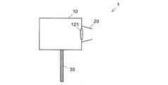
- FIG. 1 is a cross-sectional view of the visual function inspection device 1 of this embodiment (however, the configuration inside the housing 10 is not shown. See FIG. 2 for the configuration inside the housing 10.).
- the visual function test device 1 of this embodiment has a housing 10, a light-shielding portion 20 attached to the front side (subject side) of the housing 10, and a support rod 30 provided on the lower surface of the housing 10. doing.
- a peephole (window) is provided on the front side of the housing 10, and a tubular light-shielding portion 20 having a shape in which the upper part of the cone is cut off is attached so as to surround the peephole.
- a lens 121 having a predetermined numerical aperture is attached to the peephole.
- the subject is provided with a support rod 30, and the visual view formed inside the housing 10 by the eye to be inspected from a position separated from the lens 121 by a predetermined distance (for example, 5 cm). It is designed to perform a predetermined visual function test by visually recognizing a virtual image of a target.
- a visual acuity test is a visual acuity test, in which case, for example, a Randold ring is visually recognized as a predetermined optotype.
- the inside of the housing 10 is an optical system including an optotype display unit for displaying a predetermined optotype and a lens that forms a virtual image of the predetermined optotype at a position visible from a peephole. It houses a virtual image optical system with an exit pupil of a size.
- the inner wall surface of the housing 10 is painted black in order to suppress the generation of stray light in the housing 10 and to make it difficult for the subject to see the optical elements and the like in the housing 10.
- the optotype display unit of this embodiment is a backlit liquid crystal display 11.
- the liquid crystal display 11 displays a predetermined optotype under the control of a control unit (not shown).
- FIG. 2 shows the arrangement of the liquid crystal display 11 arranged in the housing 10 and the virtual image optical system.
- the camera 40 shown in FIG. 2 is used in a preferred embodiment described later.
- the virtual image optical system includes a first lens group 12 and a second lens group 13 in this order from the side closer to the peephole.
- the first lens group 12 includes a first achromatic lens 121 and a second achromatic lens 122 in this order from the side closer to the peephole.
- the second lens group 13 includes a plano-convex lens 131 and an achromatic lens 132 in this order from the side closer to the peephole.
- this plano-convex lens is only an example, and a biconvex lens, a biconcave lens, or a concavo-convex lens may be used in an appropriate combination.
- a diaphragm 14 is provided between the achromatic lens 132 and the liquid crystal display 11.
- These achromatic lenses are a combination of a negative lens and a positive lens made of members having different refractive indexes from each other, and have a function of removing chromatic aberration, thereby improving imaging performance.
- the negative lens (concave lens) refers to a lens whose central portion is thinner than the peripheral portion. With a negative lens, light parallel to the optical axis is refracted by the lens and spread.
- a positive lens refers to a lens whose central portion is thicker than its peripheral portion.
- light parallel to the optical axis (a line that passes through the center of the curved surface of the lens perpendicular to the lens) is refracted by the lens and collected at one point on the optical axis.
- the optical path of light emitted from the center of the liquid crystal display 11 is shown by a solid line
- the optical path of light emitted from the upper end is shown by a broken line
- the optical path of light emitted from the lower end is shown by a chain line.
- the liquid crystal display 11 only the light passing through the aperture 14 passes through the achromatic lens 132 and the plano-convex lens 131 of the second lens group 13 in this order, whereby the liquid crystal display 11
- the image of the optotype displayed in is imaged at the imaging position P. That is, the second lens group 13 constitutes an imaging optical system.
- the luminous flux emitted from the liquid crystal display 11 travels in the direction centered on the optical axis C and is incident on the eyes of the subject.
- the first achromatic lens 121 and the second achromatic lens 122 of the first lens group 12 are arranged so that their focal points are located farther than the position of the subject's eye at the time of the visual function test. Therefore, a virtual image of the index image formed at the imaging position P appears on the subject's eye at a predetermined distance (for example, 5 m in the case of a visual acuity test) from the subject's eye. That is, the first lens group 12 constitutes a virtual image forming optical system.
- the visual function test device 1 of this embodiment is designed so that the size of the exit pupil becomes a predetermined size, as schematically shown in FIG.
- the predetermined size is a size less than the distance between the eyes of the subject.
- the distance between the eyes of an adult is about 7 cm. Therefore, when used for visual acuity measurement using an adult as a subject, the size of the exit pupil should be less than 7 cm.
- the distance between the eyes of a child is shorter than that. Therefore, when it is used for visual acuity measurement with a child as a subject, the predetermined size is less than the inter-eye distance.
- the size of the exit pupil corresponds to the size of the luminous flux at the position of the subject's eye (shown by the size of the eye in FIG. 2; the same applies in FIG. 9 described later). There is.
- the design of the visual function test apparatus 1 will be described with an example.
- the field of view actual field of view
- the size of the exit pupil is 30 mm (less than the distance between the eyes of the subject)
- the eye relief is 200 mm, it is closest to the eye.
- the size of the exit pupil is smaller than the distance between the eyes of the subject. Therefore, for example, when examining the right eye, the right eye (the eye on the side to be examined). When visually recognizing the virtual image of the index, the virtual image is not visually recognized by the left eye (the eye on the side not to be inspected).
- the eye relief is 5 cm or more, as schematically shown in FIG.
- the eye relief is conventionally known as an index showing the characteristics of binoculars, and specifically, the distance from the eyepiece of the binoculars to the position farthest from the eyepiece within the range in which the entire field of view can be seen without chipping.
- a head-up display or a head-mounted display may not have an eyepiece (a lens paired with an objective lens).
- eye relief is more broadly interpreted as the design eye position and the distance between the optical elements located closest to the eye.
- the eye relief in this embodiment refers to the distance from the design eye position in the visual function test apparatus 1 to the optical element (first achromatic lens 121) arranged closest to the eye.
- the eye relief can be lengthened by increasing the numerical aperture of the lens 121 attached to the peephole or by reducing the optotype displayed on the liquid crystal display 11 (narrowing the field of view).
- the eye relief may be appropriately determined as long as it is 5 cm or more, but for example, it may be 30 cm or more. As a result, it is possible to suppress the intervention of the subject's unconscious adjustment of visual acuity and perform an accurate examination.
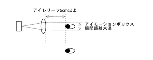
- FIGS. 4 and 5 schematically show the size of the eye relief and the exit pupil of the conventional visual acuity meter (the size of the eye motion box).
- FIG. 4 relates to the visual acuity meter described in Non-Patent Document 3.
- This visual acuity meter displays a virtual image of the optotype inside a housing provided with a forehead pad and two peepholes. The distance between the eyepiece attached to the peephole and the subject's eye when the subject's forehead is placed on the forehead is about 3 cm, and therefore the length of the eye relief is set to the same level. Since such a visual acuity meter puts the subject's forehead on the forehead to perform a visual acuity test, it tends to be unsanitary unless it is disinfected regularly.
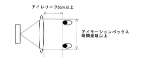
- FIG. 5 relates to the visual acuity meter described in Patent Document 1, Non-Patent Documents 4 and 5.
- a virtual image of the optotype is displayed inside the housing in which the optotype window is formed on the front surface.
- the optotype can be visually recognized without any chipping within a range of ⁇ 70 mm to the left and right and ⁇ 60 mm to the top and bottom from the center of the optotype window. That is, the size of the exit pupil (the size of the eye motion box) is equal to or larger than the inter-eye distance.
- the visual function test device 1 of the present embodiment since the size of the exit pupil of the virtual image optical system is a predetermined size (less than the distance between the eyes of the subject), the eye on the side not to be tested The virtual image is not visible. Therefore, it is not necessary for the subject to wear the jig. Further, since the eye relief is 5 cm or more and the virtual image of the optotype can be visually recognized at a position 5 cm or more away from the visual function inspection device 1, the visual function can be inspected without contact.
- the above embodiment is an example and can be appropriately modified according to the gist of the present invention.
- the size of the exit pupil is limited by the diaphragm 14, but as shown in FIG. 6, the louver 16 may be attached to the front surface of the liquid crystal display 11.
- the louver 16 is arranged so that light parallel to the optical axis C passes through the central portion of the liquid crystal display 11 and the inclination with respect to the optical axis C increases toward the end portion of the liquid crystal display 11. Thereby, the luminous flux emitted from the liquid crystal display 11 can be limited as in the case where the diaphragm 14 is provided.
- the backlight of the liquid crystal display 11 may have directivity.
- a backlight 17 may be used that illuminates the central portion of the liquid crystal display 11 in a direction parallel to the optical axis C and illuminates in a direction in which the inclination with respect to the optical axis C increases toward the end portion of the liquid crystal display 11. ..
- a backlight 17 it is possible to limit the luminous flux emitted from the liquid crystal display 11 as in the case where the diaphragm 14 is provided.
- the microlens array 18 may be attached to the front side of the liquid crystal display 11.
- the microlens array 18 is composed of a large number of minute lenses 181.
- the top of the lens 181 faces in a direction parallel to the optical axis C, and the more toward the end of the liquid crystal display 11, the more the lens 181
- the top is arranged so as to face an inclined direction with respect to the optical axis C.
- FIG. 8 shows a microlens 181 having the same shape arranged on a curved base material, but has a different shape on a flat base material (in the central portion of the liquid crystal display 11, the top of the lens 181 has an optical axis C. (The top of each microlens 181 is processed so that the top of the lens faces the direction inclined with respect to the optical axis C toward the end of the liquid crystal display 11). You can also.
- FIG. 2 shows an example in which the optical axis C from the liquid crystal display 11 to the subject's eye is in a straight line
- a mirror may be arranged at an appropriate position and the optical axis C may be bent.
- the housing (eye motion box) 10 can be compactly configured without enlarging the housing (eye motion box) 10 in a specific direction.
- a reflective optical system that gives power to the mirror (including a concave mirror and a convex mirror) may be used.
- a catadioptric system may be used, which is a combination of a mirror and a lens having power.
- the positions of each optical element and the liquid crystal display 11 may be changed.
- the imaging position P of the index is moved, and the position (distance from the subject's eye) where the virtual image of the optotype is formed is changed. can do.
- the imaging position P of the index can be moved, and the position (distance from the subject's eye) where the virtual image of the optotype is formed can be changed.
- the visual function test device 1 of the above embodiment allows the subject to hold the support rod 30, and visually recognizes a virtual image of an optotype formed inside the housing 10 supported by the support rod 30 with one eye of the subject.
- the housing 10 may be placed on the desk.
- two peepholes may be provided in one housing 10 and a lens 121 may be attached to each of them, and the virtual image optical system described with reference to FIG. 2 may be arranged at a position corresponding to each peephole. As a result, not only one eye but also both eyes can be tested for visual function.
- the camera 40 is arranged inside the housing 10, and the eye condition (eye position, eye movement, fundus, refractive index) of the subject who visually recognizes the optotype by the camera. Etc.) can also be configured to be photographed and inspected.
- the above embodiment is an example of a preferable visual function inspection device, and some of the components (optical elements and the like) included in the visual function inspection device 1 of the above embodiment may be omitted.
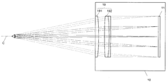
- a liquid crystal display 11 inside the housing 10 and a lens group 19 (a plano-convex lens 191 and an achromatic lens 192) constituting a virtual image of an optotype displayed on the liquid crystal display 11. It is possible that only the lens is arranged and the plano-convex lens 191 is arranged in the peephole of the housing.
- this configuration does not include an aperture, it is preferable to limit the luminous flux emitted from the display 11 by combining the configurations described with reference to FIGS. 6 to 8 in order to limit the size of the exit pupil.
- the optotype is displayed on the liquid crystal display 11, but in addition, a sheet on which a plurality of optotypes are printed in advance is arranged to illuminate the optotype from the back, and the illuminated optotype is displayed.
- An appropriate one such as a switchable one can be used.
- the tubular light-shielding portion 20 is arranged so as to surround the peephole, but the light-shielding portion 20 prevents the target from being visually recognized by the eyes on the side not to be inspected (not to be inspected). If it is a device that blocks the line of sight from the eye to the peephole), a device having an appropriate shape may be used by arranging it at an appropriate position.
- the light-shielding portion 20 may be omitted.
- the lenses 121 and 191 are attached to the peephole, but these lenses 121 and 191 are housed inside the housing 10 so that the peephole portion is opened or a transparent plate member is provided in the peephole. (A transparent member that is not an optical element) may be arranged.
- the visual function test apparatus is A housing with a peephole and An optotype display unit that displays a predetermined optotype housed in the housing, An optical system including a lens that forms a virtual image of the predetermined target at a position visible from the peephole, which is housed in the housing and has an exit pupil of a predetermined size.
- the eye relief is 5 cm or more.
- the predetermined size is less than the inter-eye distance of the subject.
- the intereye distance depends on whether the subject is a child or an adult. Therefore, this predetermined size is determined according to the subject in the visual function test.
- the visual function test device of the first item since the size of the exit pupil of the virtual image optical system is a predetermined size (less than the distance between the eyes of the subject), the virtual image cannot be visually recognized by the eyes on the side not to be inspected. Therefore, it is not necessary for the subject to wear the jig. Further, since the eye relief is 5 cm or more and the virtual image of the optotype can be visually recognized at a position 5 cm or more away from the visual function test device, the visual function can be inspected without contact.
- the virtual image optical system includes an imaging optical system that forms an image of an optotype displayed on the optotype display unit between the optotype display unit and the lens.
- the visual function inspection device of the second item by forming an image of the optotype at a position closer to the optotype display unit, it is possible to make it difficult for the eye on the side not to be inspected to see the optotype.
- the imaging optical system has a diaphragm.
- the eye relief can be adjusted by appropriately changing the size of the visual field depending on the aperture.
- the direction of the light from the optotype display unit can be restricted by the directivity imparting unit, and the optotype can be made difficult to be visually recognized by the eyes on the side not to be inspected.
- the directivity imparting portion is a louver attached to the optotype display device.
- the visual function test device of the fifth item can be easily and inexpensively configured by simply attaching a louver to the optotype display device.
- the optotype display device is a liquid crystal display.
- the directivity-imparting unit is a backlight that irradiates the directional light of the liquid crystal display.
- the backlight of the liquid crystal display is used as the directivity imparting unit, it is difficult for the visual target to be visually recognized by the eyes on the side not to be inspected without increasing the number of components. Can be done.
- the directivity imparting unit is a microlens array arranged between the optotype display device and the viewing window.
- directivity can be given to the luminous flux with high accuracy by appropriately designing the microarray lens.
- the light-shielding portion can surely prevent the visual target from being visually recognized by the eye on the side not to be inspected.
- various tests such as eye position, eye movement, fundus, and refractive index can be performed by tracking the line of sight of the subject with an imaging unit (for example, a camera).
- an imaging unit for example, a camera
- the virtual image optical system can change the position of forming the virtual image of the predetermined optotype.
- the visual function test device of the tenth item by changing the formation position of the virtual image of the optotype, it is possible to perform a peri-middle-near test, a near-point distance test of presbyopia, and the like.
Landscapes
- Life Sciences & Earth Sciences (AREA)
- Health & Medical Sciences (AREA)
- Medical Informatics (AREA)
- Biophysics (AREA)
- Ophthalmology & Optometry (AREA)
- Engineering & Computer Science (AREA)
- Biomedical Technology (AREA)
- Heart & Thoracic Surgery (AREA)
- Physics & Mathematics (AREA)
- Molecular Biology (AREA)
- Surgery (AREA)
- Animal Behavior & Ethology (AREA)
- General Health & Medical Sciences (AREA)
- Public Health (AREA)
- Veterinary Medicine (AREA)
- Eye Examination Apparatus (AREA)
Abstract
覗き穴が形成された筐体10と、前記筐体10内に収容された、所定の視標を表示する視標表示部11と、前記筐体10内に収容された、前記覗き穴から視認可能な位置に前記所定の視標の虚像を形成するレンズ121、122を含む光学系であって、所定の大きさの射出瞳を有する虚像光学系とを備え、アイレリーフが5cm以上である、視機能検査装置1。この視機能検査装置1を用いることにより、被験者に治具を装着させる必要がなく、非接触で視機能検査を行うことができる。
Description
本発明は、視機能検査装置に関する。
視機能検査の1つである視力検査では、従来、視力表に表示されるランドルト環等の所定の視標を、所定の距離(通常、5m)離れた位置から被験者に視認させて視力を測定するという方法が採られている。視力表には、非特許文献1に記載のように所定の視標を印刷したものや、非特許文献2に記載のように液晶画面に所定の視標を変更可能に表示するものが用いられる。これらを用いて視力検査を行う際には、検査対象でない側の眼に遮眼子をあてた状態で、検査対象の眼で被験者に視標を視認させる。
上記の視力検査では、視力表から上記所定の距離だけ離れた位置から被験者に視標を視認させるため、少なくともその距離以上の空間が必要である。より狭い空間でも視力検査を実施可能とするべく、所定の視標を表示する視標表示部と、上記所定の距離だけ離れた位置に該視標の虚像を形成する虚像光学系を備えた視力計が提案されている。非特許文献3には、額当てと2つの覗き穴が設けられた筐体の内部に視標の虚像を表示する視力計が記載されている。この視力計を用いた視力検査では、額当てに被験者の額を当てて固定し、検査対象でない側の眼の光路を遮断した状態で検査対象の眼に対応する覗き穴から視標の虚像を視認させる。また、特許文献1、非特許文献4及び5には、前面に視標窓が形成された筐体の内部に視標の虚像を表示する視力計が記載されている。非特許文献4には、視標窓の中心から左右に±70mm、上下に±60mmの範囲において欠けなく視標を視認可能に表示する、即ち両眼で同時に視認可能な視標を表示することが記載されている。特許文献1には、片目ごとに検査を行うために、眼前のレンズを高速で切り替えるレンズユニットを使用することが記載されている。また、非特許文献5には、片眼ごとに検査を行うために偏光メガネを使用することが記載されている。
"LED視力表 ミルカII", [online], 株式会社イナミ, [令和1年11月19日検索], インターネット<URL: http://inami.co.jp/files/topics/1358_ext_02_0.pdf>
"液晶視力表 システムチャート SC-1600", [online], 株式会社ニデック, [令和1年11月19日検索], インターネット<URL: https://www.nidek.co.jp/products/ophthalmology/exami_list/exami_acuitychart/sc-1600.html>
"自動視力計 ニデックビジョン NV-350", [online], 株式会社ニデック, [令和1年11月19日検索], インターネット<URL: https://www.nidek.co.jp/products/glasses/optical_list/optical_acuitychart/nv-350.html>
玉井ひろみ, 他10名, "視力表スペースセイビングチャート(SSC-330 type II)の有用性", Japanese Orthoptic Journal 29, 121-125, 2001-11-30, 公益社団法人 日本視能訓練士協会, インターネット<URL: https://www.jstage.jst.go.jp/article/jorthoptic1977/29/0/29_0_121/_article/-char/ja/>
"スペースセイビングチャート SSC-370 Type D", [online], 株式会社ニデック, [令和1年10月1日検索], インターネット<URL:https://www.nidek.co.jp/products/ophthalmology/exami_list/exami_acuitychart/ssc-370.html>
"診療案内", [online], 山中眼科医院, [令和1年11月19日検索], インターネット<URL:http://www.oputoyamanaka.com/guide/>
"3D ビジュアルファンクショントレイナー", [online], 株式会社JFCセールスプラン, [令和1年11月19日検索], インターネット<URL:http://www.jfcsp.co.jp/products/other-m/o-jfc/689>
非特許文献1及び2では、検査対象でない眼に遮眼子をあてて視力検査を行うが、片眼を塞いで視力検査を行うと、無意識のうちに被験者の視力の調整機能が働き検査結果が近視寄りになりやすいことが指摘されている(例えば非特許文献5、6)。特許文献1や非特許文献3~5に記載の視力計ではこのような問題が生じないが、非特許文献3に記載の視力計では額当てに被験者の額をあてて視力検査を行うため、定期的に消毒するなどしなければ不衛生になりやすい。特許文献1や非特許文献4及び5に記載の視力計では偏光メガネを装着したり、レンズユニットで遮眼したりする手間がかかり、被験者が子供である場合、そのようなメガネの装着等を嫌がることがある。
以上は視力検査を行う場合の例であるが、視力検査に限らず、眼位検査、眼球運動検査、眼底検査、屈折力検査等などの視機能検査においても上記同様の視力計が用いられており(例えば非特許文献7)、これらの視機能検査を行う場合にも上記同様の問題があった。
本発明が解決しようとする課題は、被験者に治具を装着させる必要がなく、非接触で視機能検査を行うことができる視機能検査装置を提供することである。
上記課題を解決するために成された本発明に係る視機能検査装置は、
覗き穴が形成された筐体と、
前記筐体内に収容された、所定の視標を表示する視標表示部と、
前記筐体内に収容された、前記覗き穴から視認可能な位置に前記所定の視標の虚像を形成するレンズを含む光学系であって、所定の大きさの射出瞳を有する虚像光学系と、
を備え、アイレリーフが5cm以上である。
覗き穴が形成された筐体と、
前記筐体内に収容された、所定の視標を表示する視標表示部と、
前記筐体内に収容された、前記覗き穴から視認可能な位置に前記所定の視標の虚像を形成するレンズを含む光学系であって、所定の大きさの射出瞳を有する虚像光学系と、
を備え、アイレリーフが5cm以上である。
前記虚像光学系は、例えば、凸レンズを、視標表示部が該凸レンズとその焦点の間に位置するように配置したものとすることができる。あるいは、視標表示部に表示される視標の像を1乃至複数のレンズ(リレーレンズ)により結像させるとともに、凸レンズを、該視標の結像位置が該凸レンズとその焦点の間に位置するように配置したものとすることができる。
前記所定の大きさは、被験者の眼間距離未満とする。眼間距離は被験者が子供であるか大人であるかによって異なる。従って、この所定の大きさは、視機能検査における被検者に応じて決められる。
アイレリーフは、双眼鏡の特性を表す指標として従来知られているものであり、具体的には双眼鏡の接眼レンズから視野全体が欠けなく見える範囲内の、該接眼レンズから最も離れた位置までの距離をいう。ヘッドアップディスプレイやヘッドマウントディスプレイでは、接眼レンズ(対物レンズと対になるレンズ)を有しない場合がある。こうした場合、アイレリーフは、設計上の眼の位置と、眼から最も近い位置に配される光学素子の間の距離、とより広義に解釈される。本発明に係る視機能検査装置における前記アイレリーフも同様に、該視機能検査装置における設計上の眼の位置から、眼の最も近くに配置される光学素子までの距離であって、視標表示部に表示される視標を欠けなく見える距離を意味する。そして、本発明におけるアイレリーフは5cm以上である。アイレリーフの長さは、視標の大きさ及び/又は虚像光学系に含まれるレンズの開口数に依存し、視標を小さくしたりレンズの開口数を大きくしたりすることによりアイレリーフを長くすることができる。
本発明に係る視機能検査装置では、虚像光学系が有する射出瞳の大きさが所定の大きさ(被験者の眼間距離未満)であることから、検査対象でない側の眼では虚像が視認されない。そのため、被験者に治具を装着させる必要がない。また、アイレリーフが5cm以上であり、視機能検査装置から5cm以上離れた位置で視標の虚像を視認することができるため、非接触で視機能の検査を行うことができる。
本発明に係る視機能検査装置の一実施例について、以下、図面を参照して説明する。図1は、本実施例の視機能検査装置1の横断面図(但し、筐体10内の構成の図示略。筐体10内の構成については図2参照。)である。
本実施例の視機能検査装置1は、筐体10、該筐体10の前面側(被験者側)に取り付けられた遮光部20、及び該筐体10の下面に設けられた支持棒30を有している。筐体10の前面側には覗き穴(窓)が設けられており、その覗き穴を取り囲むように、円錐の上部を切り取った形状を有する筒状の遮光部20が取り付けられている。覗き穴には、所定の開口数を有するレンズ121が取り付けられている。本実施例の視機能検査装置1は、被験者に支持棒30を持たせ、そのレンズ121から所定の距離(例えば5cm)離れた位置から検査対象の眼で筐体10の内部に形成される視標の虚像を視認させることにより所定の視機能検査を行うように設計されている。視機能検査の一例は視力検査であり、その場合、所定の視標として、例えばランドルト環を視認させる。
筐体10の内部には、所定の視標を表示する視標表示部と、覗き穴から視認可能な位置に該所定の視標の虚像を形成するレンズを含む光学系であって、所定の大きさの射出瞳を有する虚像光学系とが収容されている。該筐体10内での迷光の発生を抑制するとともに、被験者に筐体10内の光学素子等を見えにくくするため、筐体10の内部の壁面は黒色に塗装されている。本実施例の視標表示部は、バックライト方式の液晶ディスプレイ11である。液晶ディスプレイ11は、図示しない制御部による制御の下で、所定の視標を表示する。
図2に、筐体10内に配置される液晶ディスプレイ11と、虚像光学系の配置を示す。図2に示すカメラ40は、後述する好ましい一態様において用いられる。虚像光学系は、覗き穴に近い側から順に、第1レンズ群12と、第2レンズ群13とを備えている。第1レンズ群12は、覗き穴に近い側から順に、第1アクロマティックレンズ121と第2アクロマティックレンズ122を備えている。また、第2レンズ群13は、覗き穴に近い側から順に、平凸レンズ131とアクロマティックレンズ132を備えている。なお、この平凸レンズは一例にすぎず、両凸レンズ、両凹レンズ、あるいは凹凸レンズを適宜に組み合わせて用いてもよい。さらに、アクロマティックレンズ132と液晶ディスプレイ11の間には絞り14が設けられている。これらのアクロマティックレンズは、互いに屈折率が異なる部材から構成された負レンズと正レンズを組み合わせたものであり、色収差を除去する機能を有し、それによって結像性能を高めている。なお、負レンズ(凹レンズ)とは、周縁部よりも中央部の方が薄いレンズを指す。負レンズでは、光軸に平行な光はレンズによって屈折し、広がる。このとき拡散した光は、光軸上の1点から発せられているように広がる。また、正レンズ(凸レンズ)とは、周縁部よりも中央部の方が厚いレンズを指す。正レンズでは、光軸(レンズ曲面の中心をレンズに垂直に通る線)に平行な光はレンズによって屈折し、光軸上の1点に集まる。
図2には、また、液晶ディスプレイ11の中央から発せられる光の光路を実線で、上端から発せられる光の光路を破線で、下端から発せられる光の光路を一点鎖線で、それぞれ示している。これらの光路で示すように、液晶ディスプレイ11から発せられる光のうち、絞り14を通過する光のみが第2レンズ群13のアクロマティックレンズ132、平凸レンズ131を順に通過し、これにより液晶ディスプレイ11に表示される視標の像が結像位置Pで結像する。即ち、第2レンズ群13は結像光学系を構成している。液晶ディスプレイ11から発せられた光束は、光軸Cを中心軸とする方向に進行して被験者の眼に入射する。
第1レンズ群12の第1アクロマティックレンズ121と第2アクロマティックレンズ122は、それらの焦点が視機能検査時に被験者の眼の位置よりも遠く位置するように配置されている。そのため、被験者の眼には、結像位置Pで結像した指標の像の虚像が、被験者の眼から所定距離(例えば視力検査の場合、5m)離れた位置に映る。即ち、第1レンズ群12は、虚像形成光学系を構成している。
本実施例の視機能検査装置1では、図3に模式的に示すように、射出瞳の大きさが所定の大きさとなるように設計されている。所定の大きさとは被験者の眼間距離未満の大きさである。大人の眼間距離は7cm程度である。従って、大人を被験者とする視力測定に使用する場合には、射出瞳の大きさは7cm未満とする。一方、子供の眼間距離はそれよりも短い。従って、子供を被験者とする視力測定に使用する場合には、所定の大きさはその眼間距離未満とする。本実施例の視機能検査装置1において、射出瞳の大きさは被験者の眼の位置における光束の大きさ(図2では眼の大きさで図示。後述する図9においても同様)に対応している。
ここで、視機能検査装置1の設計について、一例を挙げて説明する。表示する視標の大きさで決まる視野(実視界)をφ6(6度)、射出瞳の大きさを30mm(被験者の眼間距離未満)、アイレリーフを200mmとする場合、眼から最も近くに配置する光学素子の大きさMを次式から算出することができる。
M(光学素子の大きさ)=30mm(射出瞳の大きさ)+2×200mm(アイレリーフ)×tan(6度(視野の大きさ)/2)≒51mm …(1)
M(光学素子の大きさ)=30mm(射出瞳の大きさ)+2×200mm(アイレリーフ)×tan(6度(視野の大きさ)/2)≒51mm …(1)
本実施例の視機能検査装置1では、上記のとおり、射出瞳の大きさが被験者の眼間距離未満であることから、例えば右目の検査を行う場合、右眼(検査対象の側の眼)で指標の虚像を視認する際に左目(検査対象でない側の眼)に虚像が視認されることはない。
また、本実施例の視機能検査装置1では、図3に模式的に示すように、アイレリーフが5cm以上である。アイレリーフは、双眼鏡の特性を表す指標として従来知られているものであり、具体的には双眼鏡の接眼レンズから視野全体を欠けなく見える範囲内の、該接眼レンズから最も離れた位置までの距離をいう。また、ヘッドアップディスプレイやヘッドマウントディスプレイでは、接眼レンズ(対物レンズと対になるレンズ)を有しない場合がある。こうした場合、アイレリーフは、設計上の眼の位置と、眼から最も近い位置に配される光学素子の間の距離、とより広義に解釈される。本実施例におけるアイレリーフも同様に、視機能検査装置1における設計上の眼の位置から、眼の最も近くに配置される光学素子(第1アクロマティックレンズ121)までの距離をいう。アイレリーフは覗き穴に取り付けられているレンズ121の開口数を大きくしたり、液晶ディスプレイ11に表示する視標を小さく(視野を狭く)したりすることにより長くすることができる。アイレリーフは5cm以上である限りにおいて適宜に決めればよいが、例えば30cm以上にするとよい。これにより、被験者の無意識下の視力の調整が介入するのを抑制し、正確な検査を行うことできる。
図4及び5は、従来の視力計のアイレリーフ及び射出瞳の大きさ(アイモーションボックスの大きさ)を模式的に示したものである。図4は、非特許文献3に記載の視力計に関する。この視力計では、額当てと2つの覗き穴が設けられた筐体の内部に視標の虚像を表示する。額当てに被験者の額を当てた状態での、覗き穴に取り付けられている接眼レンズと被験者の眼の距離は3cm程度であり、従って、アイレリーフの長さも同程度に設定される。こうした視力計では額当てに被験者の額をあてて視力検査を行うため、定期的に消毒するなどしなければ不衛生になりやすい。
図5は、特許文献1、非特許文献4及び5に記載の視力計に関する。この視力計では、前面に視標窓が形成された筐体の内部に視標の虚像を表示する。非特許文献4に記載されているように、視標窓の中心から左右に±70mm、上下に±60mmの範囲において欠けなく視標を視認可能である。つまり、射出瞳の大きさ(アイモーションボックスの大きさ)が眼間距離以上である。こうした視力計では、片目ごとに検査を行う場合、偏光メガネを装着する等の必要があり、被験者が子供である場合、そのようなメガネの装着を嫌がることがある。
これに対し、本実施例の視機能検査装置1では、虚像光学系が有する射出瞳の大きさが所定の大きさ(被験者の眼間距離未満)であることから、検査対象でない側の眼では虚像が視認されない。そのため、被験者に治具を装着させる必要がない。また、アイレリーフが5cm以上であり、視機能検査装置1から5cm以上離れた位置で視標の虚像を視認することができるため、非接触で視機能の検査を行うことができる。
上記実施例は一例であって、本発明の趣旨に沿って適宜に変更することができる。上記実施例の視機能検査装置1では、絞り14により射出瞳の大きさを制限する構成としたが、図6に示すように、液晶ディスプレイ11の前面にルーバー16を取り付けてもよい。ルーバー16は、液晶ディスプレイ11の中央部では光軸Cに平行な光を通過させ、液晶ディスプレイ11の端部に向かうほど光軸Cに対する傾斜が大きくなるように配置される。これにより、絞り14を設けた場合と同様に液晶ディスプレイ11から発せられる光束を制限することができる。
あるいは、図7に示すように、液晶ディスプレイ11のバックライトに指向性を有するものを用いてもよい。この場合は、液晶ディスプレイ11の中央部では光軸Cに平行な方向に照明し、液晶ディスプレイ11の端部に向かうほど光軸Cに対する傾斜が大きくなる方向に照明するバックライト17を用いればよい。このようなバックライト17を用いることによっても、絞り14を設けた場合と同様に液晶ディスプレイ11から発せられる光束を制限することができる。
あるいは、図8に示すように、液晶ディスプレイ11の前面側にマイクロレンズアレイ18を取り付けても良い。マイクロレンズアレイ18は多数の微小なレンズ181で構成され、液晶ディスプレイ11の中央部ではレンズ181の頂部が光軸Cに平行な方向を向き、液晶ディスプレイ11の端部に向かうほど、レンズ181の頂部が光軸Cに対して傾斜した方向を向くように配置したものである。こうして配置した各レンズ181を通過する光に指向性を与えることによって、絞り14を設けた場合と同様に液晶ディスプレイ11から発せられる光束を制限することができる。図8では弯曲した基材上に同一形状のマイクロレンズ181を配置したものを示したが、平板状の基材上に形状が異なる(液晶ディスプレイ11の中央部ではレンズ181の頂部が光軸Cに平行な方向を向き、液晶ディスプレイ11の端部に向かうほど、レンズの頂部が光軸Cに対して傾斜した方向を向くように、各マイクロレンズ181の頂部が加工された)レンズを用いることもできる。
図2では、液晶ディスプレイ11から被験者の眼に至る光軸Cが一直線である例を示したが、適宜の位置にミラーを配置し、光軸Cを曲げてもよい。これにより、特定の一方向に筐体(アイモーションボックス)10を大きくすることなく、コンパクトに構成することができる。また,レンズの代わりにミラーにパワーをもたせる(凹面ミラーや凸面ミラーを含んだ)反射光学系にしても良い。更に,パワーを持ったミラーとレンズの組み合わせである反射屈折光学系にしても良い。
また、上記実施例の視機能検査装置1において、各光学素子や液晶ディスプレイ11の位置を変更可能としてもよい。例えば、虚像光学系の第2レンズ群13の位置を変更することにより、指標の結像位置Pを移動し、それによって視標の虚像が形成される位置(被験者の眼からの距離)を変更することができる。あるいは液晶ディスプレイ11の位置を変更することによっても、指標の結像位置Pを移動し、それによって視標の虚像が形成される位置(被験者の眼からの距離)を変更することができる。こうした構成を採ることにより、遠中近検査や老眼の近点距離検査などを行うことができる。
さらに、上記実施例の視機能検査装置1は、被験者に支持棒30を持たせ、該支持棒30で支持されている筐体10の内部に形成する視標の虚像を被験者の片眼で視認させる構成としたが、これに代えて、筐体10を机上に置くようにしてもよい。また、1つの筐体10に覗き穴を2つ設けてそれぞれにレンズ121を取り付けるとともに、各覗き穴に対応する位置に、図2で説明した虚像光学系を配置してもよい。これにより片眼だけでなく、両眼の視機能検査を行うことができる。
さらに、上記実施例の視機能検査装置1において、筐体10の内部にカメラ40を配置し、そのカメラによって、視標を視認する被験者の眼の状態(眼位、眼球運動、眼底、屈折率等)を撮影して検査するように構成することもできる。
上記実施例は好ましい視機能検査装置の例であって、上記実施例の視機能検査装置1に含まれる構成要素(光学素子等)の一部を省略してもよい。例えば図9に変形例として示すように、筐体10の内部に液晶ディスプレイ11と、該液晶ディスプレイ11に表示される視標の虚像を構成するレンズ群19(平凸レンズ191とアクロマティックレンズ192)のみを配置し、筐体の覗き穴に平凸レンズ191を配置したものとすることができる。このように簡素な構成を採れば、装置を小型化し、また安価に製造することができる。なお、この構成は絞りを含まないため、射出瞳の大きさを制限するために、図6~図8により説明した構成を組み合わせてディスプレイ11から発せられる光束を制限するとよい。
また、上記実施例では液晶ディスプレイ11に視標を表示するものとしたが、その他、複数の視標を予め印刷したシートを配置して視標を背面から照明するとともに、照明される視標を切り替え可能に構成したものなど、適宜のものを用いることができる。さらに、上記実施例では、筒状の遮光部20を、覗き穴を取り囲むように配置したが、遮光部20は検査対象でない側の眼により視標が視認されるのを防止する(検査対象でない眼から覗き穴に向かう視線を遮断する)ものであれば適宜の形状のものを適宜の位置に配置して用いればよい。また、不要な光線を光学系で十分に遮光できるのであれば、遮光部20を省略しても良い。さらに、上記実施例では覗き穴にレンズ121、191を取り付けたが、これらのレンズ121、191を筐体10の内部に収容し、覗き穴の部分を開口にしたり、覗き穴に透明な板部材(光学素子ではない透明な部材)を配置したりしてもよい。
[態様]
上述した複数の例示的な実施形態は、以下の態様の具体例であることが当業者により理解される。
上述した複数の例示的な実施形態は、以下の態様の具体例であることが当業者により理解される。
(第1項)
本発明の一態様に係る視機能検査装置は、
覗き穴が形成された筐体と、
前記筐体内に収容された、所定の視標を表示する視標表示部と、
前記筐体内に収容された、前記覗き穴から視認可能な位置に前記所定の視標の虚像を形成するレンズを含む光学系であって、所定の大きさの射出瞳を有する虚像光学系と
を備え、アイレリーフが5cm以上である。
本発明の一態様に係る視機能検査装置は、
覗き穴が形成された筐体と、
前記筐体内に収容された、所定の視標を表示する視標表示部と、
前記筐体内に収容された、前記覗き穴から視認可能な位置に前記所定の視標の虚像を形成するレンズを含む光学系であって、所定の大きさの射出瞳を有する虚像光学系と
を備え、アイレリーフが5cm以上である。
第1項の視機能検査装置において、前記所定の大きさは、被験者の眼間距離未満とする。眼間距離は被験者が子供であるか大人であるかによって異なる。従って、この所定の大きさは、視機能検査における被検者に応じて決められる。
第1項の視機能検査装置では、虚像光学系が有する射出瞳の大きさが所定の大きさ(被験者の眼間距離未満)であることから、検査対象でない側の眼では虚像が視認されない。そのため、被験者に治具を装着させる必要がない。また、アイレリーフが5cm以上であり、視機能検査装置から5cm以上離れた位置で視標の虚像を視認することができるため、非接触で視機能の検査を行うことができる。
(第2項)
上記第1項に記載の視機能検査装置において、
前記虚像光学系は、前記視標表示部に表示される視標の像を、該視標表示部と前記レンズの間で結像させる結像光学系を備える。
上記第1項に記載の視機能検査装置において、
前記虚像光学系は、前記視標表示部に表示される視標の像を、該視標表示部と前記レンズの間で結像させる結像光学系を備える。
第2項の視機能検査装置では、視標表示部よりも近い位置に視標の像を形成することにより、検査対象でない側の眼で視標を視認されにくくすることができる。
(第3項)
上記第2項に記載の視機能検査装置において、
前記結像光学系は絞りを有する。
上記第2項に記載の視機能検査装置において、
前記結像光学系は絞りを有する。
第3項の視機能検査装置では、絞りによって視野の大きさを適宜に変更してアイレリーフを調整することができる。
(第4項)
上記第1項から第3項のいずれかに記載の視機能検査装置において、
前記視標表示部から前記覗き穴に至る光束に指向性を付与する指向性付与部を備える。
上記第1項から第3項のいずれかに記載の視機能検査装置において、
前記視標表示部から前記覗き穴に至る光束に指向性を付与する指向性付与部を備える。
第4項の視機能検査装置では指向性付与部によって視標表示部からの光の方向を制限し、検査対象でない側の眼で視標を視認されにくくすることができる。
(第5項)
上記第4項に記載の視機能検査装置において、
前記指向性付与部は、前記視標表示装置に取り付けられたルーバーである。
上記第4項に記載の視機能検査装置において、
前記指向性付与部は、前記視標表示装置に取り付けられたルーバーである。
第5項の視機能検査装置では、視標表示装置にルーバーを取り付けるのみで簡単かつ安価に構成することができる。
(第6項)
上記第4項に記載の視機能検査装置において、
前記視標表示装置は、液晶ディスプレイであり、
前記指向性付与部は、前記液晶ディスプレイが有する、指向性を有する光を照射するバックライトである。
上記第4項に記載の視機能検査装置において、
前記視標表示装置は、液晶ディスプレイであり、
前記指向性付与部は、前記液晶ディスプレイが有する、指向性を有する光を照射するバックライトである。
第6項の視機能検査装置では、液晶ディスプレイのバックライトを指向性付与部として活用するため、構成部品の数を増加することなく、検査対象でない側の眼で視標を視認されにくくすることができる。
(第7項)
上記第4項に記載の視機能検査装置において、
前記指向性付与部は、前記視標表示装置と前記覗き窓の間に配置されたマイクロレンズアレイである。
上記第4項に記載の視機能検査装置において、
前記指向性付与部は、前記視標表示装置と前記覗き窓の間に配置されたマイクロレンズアレイである。
第7項の視機能検査装置では、マイクロアレイレンズを適宜に設計することにより、精度よく光束に指向性を与えることができる。
(第8項)
上記第1項から第7項のいずれかに記載の視機能検査装置において、さらに、
前記覗き穴の周囲に取り付けられ、該覗き穴から出射する光の一部を遮光する遮光部を備える。
上記第1項から第7項のいずれかに記載の視機能検査装置において、さらに、
前記覗き穴の周囲に取り付けられ、該覗き穴から出射する光の一部を遮光する遮光部を備える。
第8項の視機能検査装置では、遮光部によって、検査対象でない側の眼で視標を視認されるのを確実に防止することができる。
(第9項)
上記第1項から第8項のいずれかに記載の視機能検査装置において、さらに、
前記覗き穴を通じて前記所定の指標を視認する被験者の視線を追跡する撮影部を備える。
上記第1項から第8項のいずれかに記載の視機能検査装置において、さらに、
前記覗き穴を通じて前記所定の指標を視認する被験者の視線を追跡する撮影部を備える。
第9項の視機能検査装置では、撮影部(例えばカメラ)で被験者の視線を追跡することにより、眼位、眼球運動、眼底、屈折率等の多様な検査を行うことができる。
(第10項)
上記第1項から第8項のいずれかに記載の視機能検査装置において、
前記虚像光学系は、前記所定の視標の虚像を形成する位置を変更可能である。
上記第1項から第8項のいずれかに記載の視機能検査装置において、
前記虚像光学系は、前記所定の視標の虚像を形成する位置を変更可能である。
第10項の視機能検査装置では、視標の虚像の形成位置を変更することにより、遠中近検査や老眼の近点距離検査などを行うことができる。
1…視機能検査装置
10…筐体
11…液晶ディスプレイ
12…第1レンズ群
121…第1アクロマティックレンズ
122…第2アクロマティックレンズ
13…第2レンズ群
131…平凸レンズ
132…アクロマティックレンズ
14…絞り
16…ルーバー
17…バックライト
18…マイクロレンズアレイ
181…レンズ
19…レンズ群
191…平凸レンズ
192…アクロマティックレンズ
20…遮光部
30…支持棒
40…カメラ
C…光軸
P…結像位置
10…筐体
11…液晶ディスプレイ
12…第1レンズ群
121…第1アクロマティックレンズ
122…第2アクロマティックレンズ
13…第2レンズ群
131…平凸レンズ
132…アクロマティックレンズ
14…絞り
16…ルーバー
17…バックライト
18…マイクロレンズアレイ
181…レンズ
19…レンズ群
191…平凸レンズ
192…アクロマティックレンズ
20…遮光部
30…支持棒
40…カメラ
C…光軸
P…結像位置
Claims (10)
- 覗き穴が形成された筐体と、
前記筐体内に収容された、所定の視標を表示する視標表示部と、
前記筐体内に収容された、前記覗き穴から視認可能な位置に前記所定の視標の虚像を形成するレンズを含む光学系であって、所定の大きさの射出瞳を有する虚像光学系と
を備え、アイレリーフが5cm以上である、視機能検査装置。 - 前記虚像光学系は、前記視標表示部に表示される視標の像を、該視標表示部と前記レンズの間で結像させる結像光学系を備える、請求項1に記載の視機能検査装置。
- 前記結像光学系は絞りを有する、請求項2に記載の視機能検査装置。
- 前記視標表示部から前記覗き穴に至る光束に指向性を付与する指向性付与部を備える、請求項1に記載の視機能検査装置。
- 前記指向性付与部は、前記視標表示装置に取り付けられたルーバーである、請求項4に記載の視機能検査装置。
- 前記視標表示装置は、液晶ディスプレイであり、
前記指向性付与部は、前記液晶ディスプレイが有する、指向性を有する光を照射するバックライトである、請求項4に記載の視機能検査装置。 - 前記指向性付与部は、前記視標表示装置と前記覗き窓の間に配置されたマイクロレンズアレイである、請求項4に記載の視機能検査装置。
- さらに、
前記覗き穴の周囲に取り付けられ、該覗き穴から出射する光の一部を遮光する遮光部を備える、請求項1に記載の視機能検査装置。 - さらに、
前記覗き穴を通じて前記所定の指標を視認する被験者の視線を追跡する撮影部を備える、請求項1に記載の視機能検査装置。 - 前記虚像光学系は、前記所定の視標の虚像を形成する位置を変更可能である、請求項1に記載の視機能検査装置。
Priority Applications (5)
| Application Number | Priority Date | Filing Date | Title |
|---|---|---|---|
| PCT/JP2020/005128 WO2021161385A1 (ja) | 2020-02-10 | 2020-02-10 | 視機能検査装置 |
| EP20919086.7A EP4104748A4 (en) | 2020-02-10 | 2020-02-10 | DEVICE FOR TESTING VISUAL FUNCTIONS |
| US17/798,388 US20230075963A1 (en) | 2020-02-10 | 2020-02-10 | Visual function test device |
| CN202080093994.XA CN115023173A (zh) | 2020-02-10 | 2020-02-10 | 视功能检查装置 |
| JP2021577733A JP7388457B2 (ja) | 2020-02-10 | 2020-02-10 | 視機能検査装置 |
Applications Claiming Priority (1)
| Application Number | Priority Date | Filing Date | Title |
|---|---|---|---|
| PCT/JP2020/005128 WO2021161385A1 (ja) | 2020-02-10 | 2020-02-10 | 視機能検査装置 |
Publications (1)
| Publication Number | Publication Date |
|---|---|
| WO2021161385A1 true WO2021161385A1 (ja) | 2021-08-19 |
Family
ID=77292189
Family Applications (1)
| Application Number | Title | Priority Date | Filing Date |
|---|---|---|---|
| PCT/JP2020/005128 WO2021161385A1 (ja) | 2020-02-10 | 2020-02-10 | 視機能検査装置 |
Country Status (5)
| Country | Link |
|---|---|
| US (1) | US20230075963A1 (ja) |
| EP (1) | EP4104748A4 (ja) |
| JP (1) | JP7388457B2 (ja) |
| CN (1) | CN115023173A (ja) |
| WO (1) | WO2021161385A1 (ja) |
Citations (6)
| Publication number | Priority date | Publication date | Assignee | Title |
|---|---|---|---|---|
| JPS5889235A (ja) * | 1981-11-13 | 1983-05-27 | エシロ−ル・アンテルナシヨナル・コムパニ−・ジエネラル・ドプテイク | 被検者に視試験標識を提示する装置 |
| JPS5899945A (ja) * | 1981-12-09 | 1983-06-14 | キヤノン株式会社 | 乱視測定装置 |
| US6042231A (en) * | 1996-08-02 | 2000-03-28 | Vega Vista, Inc. | Methods and systems for relieving eye strain |
| JP2002200041A (ja) | 2001-01-09 | 2002-07-16 | Nidek Co Ltd | 検眼装置 |
| JP2009273869A (ja) * | 2008-04-16 | 2009-11-26 | Panasonic Electric Works Co Ltd | 多機能眼科検査装置 |
| JP2015500732A (ja) * | 2011-12-20 | 2015-01-08 | ポステック アカデミー−インダストリー ファンデーション | 個人用コンピュータに基づく視野自己診断システムおよび視野自己診断方法 |
Family Cites Families (3)
| Publication number | Priority date | Publication date | Assignee | Title |
|---|---|---|---|---|
| US20180103841A1 (en) * | 2015-05-01 | 2018-04-19 | Carl Zeiss Meditec, Inc. | Systems for visual field testing |
| US11432718B2 (en) * | 2017-10-31 | 2022-09-06 | EyeQue Inc. | Smart phone based virtual visual charts for measuring visual acuity |
| CN107157437A (zh) * | 2017-06-22 | 2017-09-15 | 宁波明星科技发展有限公司 | 一种双透镜反射式液晶视力仪 |
-
2020
- 2020-02-10 CN CN202080093994.XA patent/CN115023173A/zh active Pending
- 2020-02-10 JP JP2021577733A patent/JP7388457B2/ja active Active
- 2020-02-10 EP EP20919086.7A patent/EP4104748A4/en active Pending
- 2020-02-10 WO PCT/JP2020/005128 patent/WO2021161385A1/ja unknown
- 2020-02-10 US US17/798,388 patent/US20230075963A1/en active Pending
Patent Citations (6)
| Publication number | Priority date | Publication date | Assignee | Title |
|---|---|---|---|---|
| JPS5889235A (ja) * | 1981-11-13 | 1983-05-27 | エシロ−ル・アンテルナシヨナル・コムパニ−・ジエネラル・ドプテイク | 被検者に視試験標識を提示する装置 |
| JPS5899945A (ja) * | 1981-12-09 | 1983-06-14 | キヤノン株式会社 | 乱視測定装置 |
| US6042231A (en) * | 1996-08-02 | 2000-03-28 | Vega Vista, Inc. | Methods and systems for relieving eye strain |
| JP2002200041A (ja) | 2001-01-09 | 2002-07-16 | Nidek Co Ltd | 検眼装置 |
| JP2009273869A (ja) * | 2008-04-16 | 2009-11-26 | Panasonic Electric Works Co Ltd | 多機能眼科検査装置 |
| JP2015500732A (ja) * | 2011-12-20 | 2015-01-08 | ポステック アカデミー−インダストリー ファンデーション | 個人用コンピュータに基づく視野自己診断システムおよび視野自己診断方法 |
Non-Patent Citations (5)
| Title |
|---|
| "3D Visual Function Trainer", JFC SALES PLAN CO., LTD |
| "Liquid Crystal visual acuity chart Systems Chart SC-1600", 19 November 2019, YAMANAKA OPHTHALMOLOGIC CLINIC |
| "Space Saving Chart SSC-370 Type D", 1 October 2019, NIDEK CO., LTD. |
| See also references of EP4104748A4 |
| TAMAI HIROMI: "Japanese Orthoptic Journal", vol. 29, 30 November 2001, PUBLIC INTEREST CORPORATION, article "Utility of visual acuity chart Space Saving Chart (SSC-330 type II", pages: 121 - 125 |
Also Published As
| Publication number | Publication date |
|---|---|
| EP4104748A1 (en) | 2022-12-21 |
| CN115023173A (zh) | 2022-09-06 |
| JP7388457B2 (ja) | 2023-11-29 |
| JPWO2021161385A1 (ja) | 2021-08-19 |
| EP4104748A4 (en) | 2023-01-18 |
| US20230075963A1 (en) | 2023-03-09 |
Similar Documents
| Publication | Publication Date | Title |
|---|---|---|
| JP6655121B2 (ja) | 光学測定方法 | |
| Smith et al. | The eye and visual optical instruments | |
| James | Light microscopic techniques in biology and medicine | |
| US8042945B2 (en) | Multifocal intraocular lens simulator and method of simulating multifocal intraocular lens | |
| US20170336609A1 (en) | Catadioptric eyepiece system, eyepiece system and optical system | |
| EP3210525B1 (en) | Vision examination device and head-mounted display device | |
| JP3199801B2 (ja) | 視力検査装置 | |
| US4072395A (en) | Microscope | |
| US8678834B2 (en) | Device for demonstrating and testing the effectiveness of an anti-reflective treatment of an ophthalmic lens | |
| Chirre et al. | Binocular open-view instrument to measure aberrations and pupillary dynamics | |
| WO2021161385A1 (ja) | 視機能検査装置 | |
| EP3210524B1 (en) | Vision testing device | |
| JPH11249086A (ja) | 疑似視覚レンズ並びにこれを用いた疑似視覚カメラ及び疑似視覚装置 | |
| Petrov et al. | Investigation of optical characteristics of rigid protected and traditional elastic Fresnel microprisms using electronic method for measuring visual acuity | |
| JPH09253049A (ja) | 検眼装置 | |
| Prescott | Optical principles of endoscopy | |
| JPH06165755A (ja) | 検眼装置 | |
| JP2022525675A (ja) | 個人の眼を検査するための視力測定装置及び関連する方法 | |
| Carpentras et al. | See-through ophthalmoscope for retinal imaging | |
| Sarkar | Design, Alignment, and Usage of Infinity-Corrected Microscope | |
| JPS6249924B2 (ja) | ||
| Xing et al. | Design of portable fundus camera system based on mobile phone | |
| KR102142097B1 (ko) | 시력검사기구 | |
| JPH09171147A (ja) | 接眼光学系 | |
| SU1760511A1 (ru) | Устройство дл получени увеличенного изображени объекта |
Legal Events
| Date | Code | Title | Description |
|---|---|---|---|
| 121 | Ep: the epo has been informed by wipo that ep was designated in this application |
Ref document number: 20919086 Country of ref document: EP Kind code of ref document: A1 |
|
| ENP | Entry into the national phase |
Ref document number: 2021577733 Country of ref document: JP Kind code of ref document: A |
|
| NENP | Non-entry into the national phase |
Ref country code: DE |
|
| ENP | Entry into the national phase |
Ref document number: 2020919086 Country of ref document: EP Effective date: 20220912 |