WO2021157528A1 - 画像処理装置 - Google Patents
画像処理装置 Download PDFInfo
- Publication number
- WO2021157528A1 WO2021157528A1 PCT/JP2021/003552 JP2021003552W WO2021157528A1 WO 2021157528 A1 WO2021157528 A1 WO 2021157528A1 JP 2021003552 W JP2021003552 W JP 2021003552W WO 2021157528 A1 WO2021157528 A1 WO 2021157528A1
- Authority
- WO
- WIPO (PCT)
- Prior art keywords
- detection
- image
- value
- rate
- objective function
- Prior art date
- Legal status (The legal status is an assumption and is not a legal conclusion. Google has not performed a legal analysis and makes no representation as to the accuracy of the status listed.)
- Ceased
Links
Images


Classifications
-
- G—PHYSICS
- G06—COMPUTING OR CALCULATING; COUNTING
- G06V—IMAGE OR VIDEO RECOGNITION OR UNDERSTANDING
- G06V10/00—Arrangements for image or video recognition or understanding
- G06V10/40—Extraction of image or video features
- G06V10/46—Descriptors for shape, contour or point-related descriptors, e.g. scale invariant feature transform [SIFT] or bags of words [BoW]; Salient regional features
- G06V10/469—Contour-based spatial representations, e.g. vector-coding
-
- G—PHYSICS
- G06—COMPUTING OR CALCULATING; COUNTING
- G06V—IMAGE OR VIDEO RECOGNITION OR UNDERSTANDING
- G06V10/00—Arrangements for image or video recognition or understanding
- G06V10/70—Arrangements for image or video recognition or understanding using pattern recognition or machine learning
- G06V10/74—Image or video pattern matching; Proximity measures in feature spaces
- G06V10/75—Organisation of the matching processes, e.g. simultaneous or sequential comparisons of image or video features; Coarse-fine approaches, e.g. multi-scale approaches; using context analysis; Selection of dictionaries
- G06V10/751—Comparing pixel values or logical combinations thereof, or feature values having positional relevance, e.g. template matching
-
- G—PHYSICS
- G06—COMPUTING OR CALCULATING; COUNTING
- G06V—IMAGE OR VIDEO RECOGNITION OR UNDERSTANDING
- G06V10/00—Arrangements for image or video recognition or understanding
- G06V10/40—Extraction of image or video features
- G06V10/50—Extraction of image or video features by performing operations within image blocks; by using histograms, e.g. histogram of oriented gradients [HoG]; by summing image-intensity values; Projection analysis
- G06V10/507—Summing image-intensity values; Histogram projection analysis
-
- G—PHYSICS
- G06—COMPUTING OR CALCULATING; COUNTING
- G06V—IMAGE OR VIDEO RECOGNITION OR UNDERSTANDING
- G06V10/00—Arrangements for image or video recognition or understanding
- G06V10/70—Arrangements for image or video recognition or understanding using pattern recognition or machine learning
- G06V10/77—Processing image or video features in feature spaces; using data integration or data reduction, e.g. principal component analysis [PCA] or independent component analysis [ICA] or self-organising maps [SOM]; Blind source separation
- G06V10/776—Validation; Performance evaluation
-
- G—PHYSICS
- G06—COMPUTING OR CALCULATING; COUNTING
- G06V—IMAGE OR VIDEO RECOGNITION OR UNDERSTANDING
- G06V2201/00—Indexing scheme relating to image or video recognition or understanding
- G06V2201/06—Recognition of objects for industrial automation
Definitions
- the present invention relates to an image processing device.
- An image processing device that detects an image of a specific object from the images in the field of view of the image pickup device is known.
- the feature amount is matched between the reference information representing the object (generally referred to as a model pattern, a template, etc.) and the input image acquired by the image pickup device, and the degree of matching is determined. It is common to determine that the object has been successfully detected when the level exceeds the above level (see, for example, Patent Document 1).
- Patent Document 2 as a configuration of the parameter control device, "In the first stage of collation, the registration data is narrowed down by a high-speed but low-precision collation process. Subsequently, the second stage of collation. Then, the registered data is further narrowed down from the first collation stage by the collation process of medium speed and medium accuracy. Then, in the m-th collation process, the registered data narrowed down by the plurality of collation processes in the previous stage is narrowed down. Performs low-speed but high-precision collation processing to identify one registered data. Collation speed and / or collation accuracy according to the parameters for adjusting the accuracy and speed of narrowing down the registered data at each collation stage according to the registered data. Is automatically calculated to be optimal. ”(Abstract).
- the permissible range of the distance between the feature points of the model pattern and the corresponding points in the corresponding input image is used as a detection parameter.
- a detection parameter for example, the permissible range of the distance between the feature points of the model pattern and the corresponding points in the corresponding input image.
- One aspect of the present disclosure is an image processing device that detects an image of the object in one or more input image data based on the model pattern of the object, and uses detection parameters to obtain a feature amount of the model pattern. Before setting the value of the detection parameter, the object detection unit that matches the feature amount extracted from the one or more input image data and detects the image of the object from the one or more input image data. The detection result by the object detection unit for the prepared one or more input image data, and the information representing the desired detection result when the image of the object is detected for the one or more input image data.
- the detection rate calculation unit that calculates at least one of the undetected rate and the false detection rate in the detection of the object by the object detecting unit, and at least one of the undetected rate and the false detection rate.
- the objective function value calculation unit that calculates the value of the objective function defined as a function that uses By changing the value of the detection parameter, the object detection unit detects the object, the detection rate calculation unit calculates at least one of the undetected rate and the false detection rate, and the objective function value calculation unit. It is an image processing apparatus including a detection parameter search unit that searches for the detection parameter by repeating the calculation of the value of the objective function.
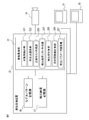
- FIG. 1 is a block diagram showing the configuration of the image processing device 21 according to the embodiment.
- a visual sensor 10, an operation panel 31, and a display device 32 are connected to the image processing device 21.
- the image processing device 21 has a function of detecting an image of a specific object from an image in the field of view of the visual sensor 10.
- the image processing device 21 may have a configuration as a general computer having a CPU, ROM, RAM, storage device, input / output interface, network interface, and the like.
- the operation panel 31 and the display device 32 may be integrally provided with the image processing device 21.
- the visual sensor 10 may be a camera that captures a grayscale image or a color image, or a stereo camera or a three-dimensional sensor that can acquire a distance image or a three-dimensional point cloud.
- a camera is used as the visual sensor 10, and the visual sensor 10 outputs a grayscale image.
- the camera is an electronic camera having an image pickup device such as a CCD (Charge Coupled Device), and is a well-known light receiving device having a function of detecting a two-dimensional image on the image pickup surface (on the CCD array surface).
- the two-dimensional coordinate system on the imaging surface is hereinafter referred to as an image coordinate system.
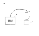
- FIG. 2 is a diagram showing a configuration example in which an object is detected by a visual sensor control device 20 having an image processing device 21 and a visual sensor 10.
- the visual sensor 10 is fixedly installed at a position where the object 1 can take an image, and the object 1 is placed on the work table 2. In this configuration, the object 1 is detected in the image captured by the visual sensor 10.
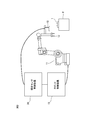
- FIG. 3 shows the hand 12 of the robot 11 controlled by the robot control device 13, and when handling the object 1 on the workbench 2, the object is taken from the image of the visual sensor 10 installed at the tip of the arm of the robot 11.
- FIG. 3 shows the configuration example which detects 1.
- the image captured by the visual sensor 10 is processed by the image processing device 21 mounted on the visual sensor control device 20, the object 1 is detected, and the position information of the detected object 1 is controlled by the robot. It supplies to the device 13.
- the visual sensor 10 may be installed in a movable portion such as an arm tip portion of the robot 11.
- the image processing device 21 includes an image processing unit 22, a model pattern storage unit 26, and a detection result storage unit 27.
- the image processing unit 22 includes an object detection unit 221, a corresponding point selection unit 222, a correct answer list creation unit 223, a detection result list creation unit 224, a detection rate calculation unit 225, an objective function value calculation unit 226, and the like. It has a detection parameter search unit 227.
- Each function of the image processing device 21 shown in FIG. 1 may be realized by the CPU of the image processing device 21 executing various software stored in the storage device, or ASIC (Application Specific Integrated IC). It may be realized by a configuration mainly composed of hardware such as.
- the object detection unit 221 has, for each of one or a plurality of input images (input image data) in which the object is captured, a plurality of second feature points extracted from the input image and a plurality of plurality of input images constituting the model pattern. Matching with the first feature point is performed to detect one or more images of the object.
- the corresponding point selection unit 222 constitutes a model pattern from a plurality of second feature points constituting the image for each of the images of the one or a plurality of objects detected from the one or a plurality of input images. A second feature point corresponding to the feature point of is selected, and the second feature point is stored in association with the first feature point as a corresponding point.
- the correct answer list creation unit 223 determines whether the detection result obtained by performing the detection process on one or more input images including the image in which the detection target is captured is the correct detection result by the operator or incorrect. It accepts the operation of inputting the detection result, and creates a correct answer list (that is, information representing the detection result desired by the operator) consisting only of the correct detection results.
- the detection result list creation unit 224 uses the set detection parameters to perform detection processing on one or more input images including an image in which the detection target is captured, and the detection result and the detection processing. Create a detection result list that records the processing time required for.
- the detection rate calculation unit 225 compares the detection result list created by the detection result list creation unit 224 with the correct answer list, and calculates at least one of the undetected rate and the false detection rate.
- the objective function value calculation unit 226 calculates the value of the objective function defined as a function having at least one of the undetected rate and the false positive rate as an input variable.
- the detection parameter search unit 227 changes the value of the detection parameter until the value of the objective function satisfies a predetermined condition or the number of searches for the detection parameter reaches a specified number, and the detection, undetected rate, and error of the object are detected.
- the detection parameters are searched by repeating the calculation of the detection rate and the calculation of the value of the objective function.
- the visual sensor 10 is connected to the image processing device 21 with a communication cable.
- the visual sensor 10 supplies the captured image data to the image processing device 21.
- the operation panel 31 is connected to the image processing device 21 with a communication cable.
- the operation panel 31 is used to set the visual sensor 10 necessary for detecting the object 1 in the image processing device 21.
- the display device 32 is connected to the image processing device 21 with a communication cable.
- the display device 32 displays an image captured by the visual sensor 10 and setting contents set by the operation panel 31.
- the image processing device 21 matches the feature amount between the reference information (called a model pattern, a template, etc.) representing the object and the input image acquired by the visual sensor 10, and the degree of matching is a predetermined level (referred to as a degree of matching).
- a degree of matching a predetermined level
- the threshold value is exceeded, it is determined that the object has been successfully detected.
- the range of the distance between the feature points of the model pattern and the corresponding points of the corresponding input image (hereinafter referred to as "allowable distance of the corresponding points") is set as a detection parameter. .. In this case, if a small value is set as the detection parameter, the degree of matching may decrease and the object to be detected may not be found.
- the image processing device 21 has a function of automatically setting detection parameters suitable for obtaining the detection result expected by the operator without trial and error of the operator.
- the image processing device 21 sets detection parameters suitable for obtaining the detection result expected by the operator by the following algorithm.
- (Procedure A11) A list of detection results (correct answer list) as expected by the operator is created for one or more input images including an image showing the detection target.
- (Procedure A12) A new detection parameter is set, and detection is performed on the input image used in the above (procedure A11) (that is, one or a plurality of input images prepared in advance before setting the value of the detection parameter). By doing so, a new detection result is acquired. At that time, the processing time required for detection is recorded (creation of detection list).
- Bayesian optimization is one of the black box optimization methods, and is a method of searching for an input having the minimum output for a function (black box function) whose output value for an input is known but difficult to formulate.
- Random search is a search method that randomly sets the values of detection parameters. In this embodiment, Bayesian optimization is used to search for detection parameters.
- the objective function uses a weighted undetected rate, false positive rate, and processing time required for detection.
- the operator can determine which value of the undetected rate, the false detection rate, and the processing time required for detection is prioritized and minimized. For example, if the weight of the false positive rate is increased, the detection parameter for fail-safe detection that eliminates false positives even if undetected occurs is preferentially searched. On the other hand, if the weight of the undetected rate is increased, it is possible to obtain a detection parameter particularly suitable for suppressing the occurrence of undetected. Further, by increasing the weight of the processing time, it is possible to obtain a detection parameter particularly suitable for reducing the processing time.
- the correct answer list creation unit 223 creates a list of detection results (correct answer list) as expected by the operator for one or more input images including an image in which the detection target is captured by the following algorithm.
- Detection is performed on one or more input images including an image showing a detection target, and the detection result is acquired.
- the detection result includes information on the detected image, detection position, posture, and size.
- the operator accepts a labeling operation for each detection result.
- the detection rate calculation unit 225 calculates the undetected rate and the false detection rate when the image data set is detected with the newly set detection parameters by the following algorithm.
- (Procedure A31) It is determined whether or not the detection result newly acquired for the input image matches the detection result included in the correct answer list. When the difference in detection position, posture, and size is within the set threshold value, it is determined that the detection results match.
- (Procedure A32) All the determination results are totaled, and the undetected rate and the false detection rate are calculated. If all the detection results included in the correct answer list are included in the newly acquired detection result list, the undetected rate is set to zero, and any detection result not included in the correct answer list is included in the newly acquired detection result list. If it is not included, the false positive rate is set to zero. If what the operator expects is properly detected, both the undetected rate and the false positive rate will be zero.
- FIG. 4 is a flowchart showing a process (hereinafter, referred to as a detection parameter setting process) that specifically realizes the above-mentioned algorithm for setting a detection parameter suitable for obtaining the detection result expected by the operator.
- the detection parameter setting process is executed under the control of the CPU of the image processing device 21.
- the detection parameters the above-mentioned “allowable distance of the corresponding point” and the “threshold value of the degree of coincidence" between the feature amount of the model pattern and the feature amount extracted from the input image are used.
- step S1 the model pattern is taught (step S1). That is, in step S1, the image processing unit 22 creates a model pattern, and the created model pattern is stored in the model pattern storage unit 26.
- the model pattern in this embodiment is composed of a plurality of feature points.
- Various objects can be used as the feature points, but in the present embodiment, the edge points are used as the feature points.
- the edge point is a point having a large luminance gradient in the image and can be used to acquire the contour shape of the object 1.
- As a method for extracting edge points various methods known in the art can be used.
- the physical quantity of the edge point includes the position of the edge point, the direction of the luminance gradient, the magnitude of the luminance gradient, and the like. If the direction of the brightness gradient of the edge point is defined as the posture of the feature point, the position and posture of the feature point can be defined together with the position. In the present embodiment, the physical quantity of the edge point, that is, the position of the edge point, the attitude (direction of the luminance gradient), and the magnitude of the luminance gradient are stored as the physical quantity of the feature point.
- FIG. 6 is a diagram showing an example of a model pattern of the object 1.
- the origin of the model pattern coordinate system 100 may be defined in any way.
- an arbitrary one point may be selected from the first feature points constituting the model pattern and defined as the origin, or the centers of gravity of all the feature points constituting the model pattern may be defined as the origin. May be good.
- the posture (axis direction) of the model pattern coordinate system 100 may be defined in any way.
- the image coordinate system and the model pattern coordinate system 100 may be defined to be parallel to each other in the image in which the model pattern is created, or any two points may be selected from the feature points constituting the model pattern.
- the direction from one of them to the other may be defined to be the X-axis direction.
- the first feature point P_i constituting the model pattern is stored in the model pattern storage unit 26 in the format shown in Table 1 below (including the size of the position, the posture, and the luminance gradient).
- FIG. 5 is a flowchart showing a procedure for creating a model pattern by the image processing unit 22 in step S1 of FIG.
- the object 1 to be taught as a model pattern is arranged in the field of view of the visual sensor 10, and an image of the object 1 is captured. It is desirable that the positional relationship between the visual sensor 10 and the object 1 at this time is the same as when the object 1 is detected.
- step S202 the area in which the object 1 is reflected in the captured image is designated as a model pattern designation area with a rectangle or a circle.
- FIG. 7 is a diagram showing an example of a model pattern designation region in the captured image. As shown in FIG. 7, the image coordinate system 210 is defined in the captured image, and the model pattern designation area (here, the rectangular area) 220 is designated so as to include the image 1A of the object 1.
- the model pattern designation area 220 is a portion where the image processing unit 22 has a large luminance gradient in the image even if the image processing unit 22 receives and sets an instruction input by the operation panel 31 while viewing the image on the display device 32. May be obtained as the outline of the image 1A and automatically specified so that the image 1A is included inside.
- step S203 edge points are extracted as feature points within the range of the model pattern designation area 220, and physical quantities such as the position of the edge points, the posture (direction of the luminance gradient), and the magnitude of the luminance gradient are obtained. Further, the model pattern coordinate system 100 is defined in the designated area, and the positions and orientations of the edge points are converted from the values represented by the image coordinate system 210 to the values represented by the model pattern coordinate system 100.
- step S204 the physical quantity of the extracted edge points is stored in the model pattern storage unit 26 as the first feature point P_i constituting the model pattern.
- edge points are used as feature points, but the feature points that can be used in this embodiment are not limited to edge points.
- SIFT Scale-Invariant Feature Transform
- You may use feature points such as.
- a line segment is formed so as to match the contour line of the object in the image.
- a model pattern may be created by arranging geometric figures such as minutes, rectangles, and circles. In that case, feature points may be provided at appropriate intervals on the geometric figure forming the contour line.
- a model pattern can be created based on CAD data or the like.
- steps S2 to S5 lists the detection results as expected by the operator for one or more input images including the image in which the detection target is captured. Create a correct answer list).
- the processes of steps S2 to S5 correspond to the above-mentioned algorithms for creating a correct answer list (procedures A21 to A23).
- the threshold value of the degree of coincidence is set low and the permissible distance of the corresponding points is set large (step S2).
- the image 1A of the object 1 (hereinafter, may be simply referred to as the object 1) is detected for each of one or a plurality of input images including the image in which the detection target is reflected, and the detection result is acquired (hereinafter, may be simply referred to as the object 1).
- Step S3 the detection result includes information on the detected image, detection position, posture, and size.
- Step 101 Detection of object
- Step 102 Selection of corresponding points
- Step 103 Evaluation based on detection parameters
- step 101 detection of the object
- the second feature point is extracted from the input image I_j.
- the second feature point may be extracted by the same method as the method of extracting the first feature point when creating the model pattern.
- edge points are extracted from the input image and used as the second feature points.
- the second feature point Q_jk is stored in the detection result storage unit 27 in association with the input image I_j. At this point, the position and orientation of the second feature point Q_jk are represented by the image coordinate system 210.
- the second feature point Q_jk extracted from the input image I_j is matched with the first feature point P_i that constitutes the model pattern, and the object 1 is detected.
- the object 1 is detected.
- generalized Hough transform RANSAC (Random Sample Consensus), ICP (Iterative Closest Point) algorithm known in the art can be used.
- NT_j images of the object are detected from the input image I_j.
- the detection position R_Tjg is the position and orientation of the image T_jg of the object viewed from the image coordinate system 210, that is, the position and orientation of the model pattern coordinate system 100 as seen from the image coordinate system 210 when the model pattern is superimposed on the image T_jg. It is a homogeneous transformation matrix to be represented, and is represented by the following equation.
- (x, y) is the position on the image
- ⁇ is the amount of rotational movement on the image.
- s is the ratio of the size of the taught model pattern to the size of the image T_jg of the object.
- the detection position R_Tjg is stored in the detection result storage unit 27 in association with the input image I_j.
- step 102 selection of corresponding points
- R_Pi the position and orientation of the first feature points P_i constituting the model pattern.
- R_Pi can be described as follows.
- t_Pi (tx_Pi, ty_Pi) is the position of P_i in the model pattern coordinate system
- v_Pi (vx_Pi, vy_Pi) is the posture of P_i in the model pattern coordinate system.
- the position and orientation of the second feature point_Q_jk extracted from the input image I_j will also be represented by the homogeneous transformation matrix R_Qjk.
- the position / orientation R_Pi of the first feature point P_i constituting the model pattern is represented by the model pattern coordinate system
- the position / orientation R_Qjk of the second feature point Q_jk extracted from the input image I_j is the image coordinate system. It should be noted that it is expressed by. Therefore, the relationship between the two will be clarified.
- R_Pi' the position and orientation of the first feature point P_i seen from the image coordinate system when the model pattern is superimposed on the image T_jg of the object reflected in the image I_j.
- R_Qjk' is Q_jk seen from the image coordinate system.
- the position of P_i seen from the image coordinate system is t_Pi'
- the posture of P_i seen from the image coordinate system is v_Pi'
- the position of Q_jk seen from the image coordinate system is t_Qjk
- v_Qjk be the attitude of Q_jk as seen
- t_Qjk' be the position of Q_jk as seen from the model pattern coordinate system
- v_Qjk' as the attitude of Q_jk as seen from the model pattern coordinate system.
- the position and orientation R_Pi of the first feature point P_i constituting the model pattern is the position seen from the image coordinate system by the equation (1). Convert to posture R_Pi'.
- the closest one is searched from the second feature points Q_jk.
- the following methods can be used for the search.
- (A) Calculate the distance between the position and orientation R_Pi'of the first feature point and the position and orientation R_Qjk of all the second feature points, and select the second feature point Q_jk that is the closest.
- (B) In a two-dimensional array having the same number of elements as the number of pixels of the input image I_j, the position / orientation R_Qjk of the second feature point is stored in the elements of the two-dimensional array corresponding to the pixel at that position, and the second of the two-dimensional array. The position and orientation of the feature point 1 The vicinity of the pixel corresponding to the orientation R_Pi is two-dimensionally searched, and the second feature point Q_jk found first is selected.
- the selected second feature point Q_jk is appropriate as a corresponding point of the first feature point P_i. For example, the distance between the position / orientation R_Pi'of the first feature point P_i and the position / orientation R_Qjk of the second feature point Q_jk is calculated, and if the distance is less than or equal to the threshold value, the selected second feature point Q_jk is the first. It is assumed that it is appropriate as a corresponding point of the feature point P_i of 1.
- the difference in physical quantities such as the attitude and the magnitude of the brightness gradient between the first feature point P_i and the second feature point Q_jk is also evaluated, and the first feature selected when they are also below or above the threshold value. It may be determined that the feature point Q_jk of 2 is appropriate as the corresponding point of the first feature point P_i.
- R_Oim R_Qjk, which is the position / orientation seen from the image coordinate system, so it is converted to the position / orientation R_Oim'viewed from the model pattern coordinate system. Try to remember it afterwards.
- procedure 103 evaluation based on detection parameters
- the second feature point selected by the above procedure 102 selection of the corresponding point
- the "allowable distance of the corresponding point” is used as the detection parameter.
- the distance between the first feature point P_i and the corresponding second feature point Q_jk when the model pattern is superimposed on the image T_jg is equal to or less than the "allowable distance of the corresponding point”
- the corresponding point (second feature) The feature point) is considered to be appropriate.
- a valid correspondence point is stored in the detection result storage unit 27 as the correspondence point O_i of P_i.
- step S4 the detection result is labeled.
- the operator visually checks and labels the correct / incorrect answer (whether it was detected correctly or falsely detected).
- FIG. 8 shows, as an example, a state in which images A11-A18 of eight objects are detected from the input image by the detection process (procedures 101 to 103) in step S3 and displayed on the display device 32. ..
- the operator labels each of the detected images with a correct answer (OK) / incorrect answer (NG).
- OK / NG may be switched by clicking the portion of the label image 301 on the image.
- the operator makes the correct answer for the images A11, A13-A16, and A18, and makes the incorrect answer for the images A12 and A17.
- step S5 only the detection result labeled as correct is extracted from the detection result, and the extracted detection result is used as the detection result (correct answer list) expected by the operator for the input image.
- the correct answer list includes images A11, A13-A16, and A18.
- the detection parameter is searched by Bayesian optimization.
- new detection parameters threshold of matching degree and permissible distance of corresponding points
- the above-mentioned detection processing procedures 101 to 103 is performed on the input image used for creating the correct answer list.
- Acquires the detection result in step S7).
- the detection result includes information on the detected image, detection position, posture, and size. At this time, the processing time required for detection is recorded.
- step S8 the detection rate calculation unit 225 compares the detection result obtained in step S7 with the correct answer list, and by comparing the detection result obtained in step S7 with the detection result list newly set in step S6, the detection parameters (threshold value of matching degree and tolerance of corresponding points) are allowed. Calculate the undetected rate and false positive rate when the input image is detected by (distance).
- the detection rate calculation unit 225 has a threshold value in which the images to be detected are the same (the ID numbers attached to the images are the same), and the difference between the detection position, the posture, and the size is set in advance. When it is within the range, it is determined that the detection results match.
- the detection rate calculation unit 225 calculates the undetected rate so that the undetected rate becomes zero when all the detected results included in the correct answer list are included in the newly acquired detection results. Further, the detection rate calculation unit 225 calculates the false detection rate so that the false detection rate becomes zero when none of the detection results not included in the correct answer list are included in the newly acquired detection result list. Specifically, when the number of images included in the correct answer list is N and the number of images detected by the new detection parameter in the correct answer list is m 0 , the detection rate calculation unit 225 , The undetected rate may be calculated by the following formula.
- step S9 the objective function value calculation unit 226 inputs the undetected rate and the false detection rate calculated in step S8 and the processing time required for detection in step S7 by the weight value input operation. Calculate the value of the objective function weighted by the weighted value.
- the objective function value calculation unit 226 accepts the input of the weight value by the operation through the operation panel 31 by the operator.
- x 1 , x 2 , and x 3 are the undetected rate, the false detection rate, and the processing time, respectively
- w 1 , w 2 , and w 3 are the weight values for x 1 , x 2 , and x 3, respectively.
- the objective function f is expressed by the following mathematical formula.
- the objective function is calculated as described above, and when the value of the objective function becomes smaller than the preset value (S10: YES) or when a specified number of searches are performed (S11: YES), the search ends.
- the objective function is equal to or greater than the set value and the specified number of searches has not been completed (S10: NO, S11: NO)
- the series of processes from steps S6 to S11 for setting new detection parameters and performing detection is repeated. Execute.
- the objective function is calculated as described above, and the search for the detection parameter is terminated when the value of the objective function is minimized or sufficiently reduced.
- the parameter setting process it is possible to automatically set the optimum detection parameter for obtaining the detection result expected by the operator without trial and error of the operator.
- the image processing device 21 sets the detection parameters obtained by the above processing as detection parameters used for detecting the object.
- the "allowable distance of the corresponding point" and the “threshold of the degree of coincidence” are used as the detection parameters, but these are examples, and other detection parameters are used in place of or in addition to these. You may.
- an allowable range may be set in the brightness gradient direction of the edge point, or an allowable range may be set in the magnitude of the brightness gradient of the edge point.
- the operator In the loop processing of steps S6 to S11 in the detection parameter setting processing shown in FIG. 4 (that is, the detection parameter search processing in Bayesian optimization), the operator previously calculates some detection parameters and the values of the objective function. It may be given to reduce the search processing time (number of searches).
- a function having three input variables of an undetected rate, a false detection rate, and a processing time is used as the objective function f, but at least one of these input variables is used as an input variable.
- An objective function may be used. For example, when an objective variable whose input variable is the undetected rate is used, it is possible to search for a detection parameter suitable for reducing the undetected rate.
- the detection rate calculation unit 225 may be configured to calculate either the undetected rate or the false detection rate.
- the program that executes various processes such as the detection parameter setting process in the above-described embodiment includes various computer-readable recording media (for example, semiconductor memory such as ROM, EEPROM, flash memory, magnetic recording medium, CD-ROM, etc.). It can be recorded on an optical disk such as a DVD-ROM.
- semiconductor memory such as ROM, EEPROM, flash memory, magnetic recording medium, CD-ROM, etc.
- optical disk such as a DVD-ROM.
Landscapes
- Engineering & Computer Science (AREA)
- Theoretical Computer Science (AREA)
- Computer Vision & Pattern Recognition (AREA)
- Physics & Mathematics (AREA)
- General Physics & Mathematics (AREA)
- Multimedia (AREA)
- Health & Medical Sciences (AREA)
- Artificial Intelligence (AREA)
- Computing Systems (AREA)
- Databases & Information Systems (AREA)
- Evolutionary Computation (AREA)
- General Health & Medical Sciences (AREA)
- Medical Informatics (AREA)
- Software Systems (AREA)
- Image Analysis (AREA)
Abstract
Description
(手順A11)検出対象が写った画像が含まれる一乃至複数の入力画像に対する、操作者の期待通りの検出結果のリスト(正解リスト)を作成する。
(手順A12)新たに検出パラメータを設定し、上記(手順A11)で使用した入力画像(すなわち、検出パラメータの値の設定前に予め準備された一乃至複数の入力画像)に対して検出を行うことで、新たに検出結果を取得する。その際に、検出にかかった処理時間を記録する(検出リストの作成)。
(手順A13)新たに取得した検出結果を正解リストと比較することで、新たに設定した検出パラメータで上記(手順A11)で使用した入力画像に対して検出を行った時の未検出率、誤検出率を計算する。
(手順A14)計算した未検出率、誤検出率及び記録した検出にかかった処理時間から目的関数の値を計算する。目的関数は、未検出率、誤検出率及び検出にかかる処理時間を操作者が任意の値で重みづけしたものを使用する。
(手順A15)目的関数の値が設定した値より小さくなった時、または規定数の検出パラメータを探索した時に、検出パラメータの探索を終了する。条件を満たさない場合は、新しい検出パラメータの探索を行う(手順A12に戻る)。
(手順A16)探索した検出パラメータの中で、目的関数の値が最小の時の検出パラメータを画像処理装置に設定する。
(手順A21)検出対象が写った画像が含まれる一乃至複数の入力画像に対して検出を行い、検出結果を取得する。検出結果には検出した画像、検出位置、姿勢、サイズの情報が含まれる。ここでは、誤検出が多くても未検出がないまたは少ないことが望ましいので、比較的多くの検出結果が得られるように検出パラメータを比較的緩い値に設定して検出を行う。
(手順A22)操作者による各検出結果に対するラベル付けの操作を受け付ける。通常は操作者が目視で確認して、正解/不正解(正しく検出できたか、誤検出だったか)のラベルを付ける。
(手順A23)検出結果から正解のラベルを付けた検出結果だけを抜き出し、入力画像に対する操作者の期待通りの検出結果のリスト(正解リスト)を作成する。
(手順A31)入力画像に対し新たに取得した検出結果が、正解リストに含まれる検出結果と一致するかを判定する。検出位置、姿勢、サイズの差が設定した閾値内に収まっている時に、その検出結果が一致すると判定する。
(手順A32)全ての判定結果を合計し、未検出率、誤検出率を計算する。正解リストに含まれる全ての検出結果が新たに取得した検出結果のリストに含まれる場合に未検出率をゼロとし、正解リストに含まれない検出結果が新たに取得した検出結果のリストに一つも含まれない場合に誤検出率をゼロとする。操作者の期待したものが適切に検出される場合、未検出率、誤検出率は共にゼロになる。

手順101:対象物の検出
手順102:対応点の選択
手順103:検出パラメータに基づく評価

a00=cosθ
a01=-sinθ
a02=x
a10=sinθ
a11=cosθ
a12=y
ただし、(x、y)は画像上での位置、θは画像上での回転移動量である。
a00=s・cosθ
a01=-s・sinθ
a02=x
a10=s・sinθ
a11=s・cosθ
a12=y
ただし、sは教示されたモデルパターンの大きさと対象物の像T_jgの大きさの比である。


b01=-vy_Pi
b02= tx_Pi
b10= vy_Pi
b11= vx_Pi
b12= ty_Pi
ただし、t_Pi =(tx_Pi, ty_Pi)はモデルパターン座標系でのP_iの位置、v_Pi =(vx_Pi, vy_Pi)はモデルパターン座標系でのP_iの姿勢である。
R_Pi'=R_Tjg・R_Pi ・・・(1)
R_Qjk'=R_Tjg-1・R_Qjk ・・・(2)
(ア)第1の特徴点の位置姿勢R_Pi’と全ての第2の特徴点の位置姿勢R_Qjkとの距離を計算し、最も距離が近い第2の特徴点Q_jkを選択する。
(イ)入力画像I_jの画素数と同じ要素数の2次元配列に、第2の特徴点の位置姿勢R_Qjkをその位置の画素に対応する2次元配列の要素に格納し、2次元配列の第1の特徴点の位置姿勢R_Piに対応する画素近傍を2次元的に探索し、最初に見つかった第2の特徴点Q_jkを選択する。


(未検出率)=(N-m0)/N
また、正解リストに含まれる像の数をN個、新たな検出パラメータで検出にされた像のうち正解リストに含まれない像の数をm1個とするとき、また、検出率計算部225は、以下の数式により誤検出率を算出しても良い。
(誤検出率)=m1/N

10 視覚センサ
11 ロボット
12 ハンド
20 視覚センサ制御装置
21 画像処理装置
22 画像処理部
31 操作盤
32 表示装置
221 対象物検出部
222 対応点選択部
223 正解リスト作成部
224 検出結果リスト作成部
225 検出率計算部
226 目的関数値計算部
227 検出パラメータ探索部
Claims (6)
- 対象物のモデルパターンに基づいて1以上の入力画像データ中の前記対象物の像を検出する画像処理装置であって、
検出パラメータを用いて前記モデルパターンの特徴量と前記1以上の入力画像データから抽出された特徴量とのマッチングを行い前記1以上の入力画像データから前記対象物の像を検出する対象物検出部と、
前記検出パラメータの値の設定前に予め準備された前記1以上の入力画像データに対する前記対象物検出部による検出結果と、前記1以上の入力画像データに対して前記対象物の像の検出を行った場合の所望の検出結果を表す情報とを比較することで、前記対象物検出部による前記対象物の検出における未検出率と誤検出率の少なくともいずれかを算出する検出率計算部と、
前記未検出率と前記誤検出率の少なくとも一方を入力変数とする関数として定義される目的関数の値を算出する目的関数値計算部と、
前記目的関数の値が所定の条件を満たすか又は前記検出パラメータの探索回数が規定数に達するまで前記検出パラメータの値を変更して前記対象物検出部による前記対象物の検出、前記検出率計算部による前記未検出率と前記誤検出率の少なくともいずれかの算出、及び前記目的関数値計算部による前記目的関数の値の算出を繰り返すことにより前記検出パラメータの探索を行う検出パラメータ探索部と、
を備える画像処理装置。 - 前記目的関数は、前記未検出率、前記誤検出率、及び前記対象物検出部による前記対象物の像の検出に要した処理時間のそれぞれに対して重み値を乗じて加算した値として定義される請求項1に記載の画像処理装置。
- 前記対象物検出部は、前記モデルパターンの第1の特徴点と前記1以上の入力画像データから抽出される第2の特徴点との間でマッチングを行い、
前記検出パラメータは、前記第1の特徴点と当該第1の特徴点に対応する前記1以上の入力画像データ中の前記第2の特徴点との間の許容距離を含む、請求項1又は2に記載の画像処理装置。 - 前記検出パラメータは、前記モデルパターンの前記第1の特徴点の総数に対する、前記第1の特徴点に対応する前記第2の特徴点として前記許容距離内にあるものの数の比率として定義される一致度についての閾値を更に含む、請求項3に記載の画像処理装置。
- 前記所定の条件は、前記目的関数の値が予め設定した設定値よりも低くなることである、請求項1から4のいずれか一項に記載の画像処理装置。
- 前記検出パラメータ探索部は、前記検出パラメータの探索にベイズ最適化、ランダムサーチのいずれかを用いる、請求項1から5のいずれか一項に記載の画像処理装置。
Priority Applications (5)
| Application Number | Priority Date | Filing Date | Title |
|---|---|---|---|
| DE112021000890.0T DE112021000890T5 (de) | 2020-02-04 | 2021-02-01 | Bildverarbeitungsvorrichtung |
| US17/794,070 US12205347B2 (en) | 2020-02-04 | 2021-02-01 | Image processing device |
| CN202180011524.9A CN115004246B (zh) | 2020-02-04 | 2021-02-01 | 图像处理装置 |
| JP2021575785A JP7324317B2 (ja) | 2020-02-04 | 2021-02-01 | 画像処理装置 |
| JP2023112951A JP7502528B2 (ja) | 2020-02-04 | 2023-07-10 | 画像処理装置 |
Applications Claiming Priority (2)
| Application Number | Priority Date | Filing Date | Title |
|---|---|---|---|
| JP2020-017190 | 2020-02-04 | ||
| JP2020017190 | 2020-02-04 |
Publications (1)
| Publication Number | Publication Date |
|---|---|
| WO2021157528A1 true WO2021157528A1 (ja) | 2021-08-12 |
Family
ID=77199280
Family Applications (1)
| Application Number | Title | Priority Date | Filing Date |
|---|---|---|---|
| PCT/JP2021/003552 Ceased WO2021157528A1 (ja) | 2020-02-04 | 2021-02-01 | 画像処理装置 |
Country Status (5)
| Country | Link |
|---|---|
| US (1) | US12205347B2 (ja) |
| JP (2) | JP7324317B2 (ja) |
| CN (1) | CN115004246B (ja) |
| DE (1) | DE112021000890T5 (ja) |
| WO (1) | WO2021157528A1 (ja) |
Cited By (1)
| Publication number | Priority date | Publication date | Assignee | Title |
|---|---|---|---|---|
| JPWO2023084900A1 (ja) * | 2021-11-10 | 2023-05-19 |
Families Citing this family (1)
| Publication number | Priority date | Publication date | Assignee | Title |
|---|---|---|---|---|
| JP7648460B2 (ja) * | 2021-07-12 | 2025-03-18 | 株式会社日立製作所 | 調整支援システムおよび調整支援方法 |
Citations (4)
| Publication number | Priority date | Publication date | Assignee | Title |
|---|---|---|---|---|
| JP2001525579A (ja) * | 1997-11-28 | 2001-12-11 | クァリア・コンピューティング・インコーポレーテッド | 乳房x線デジタル像からのクラスター化微小カルシウム沈着の自動検出 |
| JP2005128628A (ja) * | 2003-10-21 | 2005-05-19 | Toshiba Corp | パターン識別における照合に用いられるテンプレートの生成ならびに同テンプレートを用いたパターン識別のための方法、装置、およびプログラム |
| JP2017091079A (ja) * | 2015-11-06 | 2017-05-25 | ファナック株式会社 | 入力データから検出対象物の像を検出する画像処理装置および方法 |
| JP2017151813A (ja) * | 2016-02-25 | 2017-08-31 | ファナック株式会社 | 入力画像から検出した対象物を表示する画像処理装置 |
Family Cites Families (9)
| Publication number | Priority date | Publication date | Assignee | Title |
|---|---|---|---|---|
| US7167583B1 (en) * | 2000-06-28 | 2007-01-23 | Landrex Technologies Co., Ltd. | Image processing system for use with inspection systems |
| JP5391631B2 (ja) | 2008-10-03 | 2014-01-15 | 富士通株式会社 | パラメタ制御装置、パラメタ制御プログラム及び多段照合装置 |
| JP2010097436A (ja) * | 2008-10-16 | 2010-04-30 | Keyence Corp | 画像処理におけるパターンモデルの位置決め方法、画像処理装置、画像処理プログラム及びコンピュータで読み取り可能な記録媒体 |
| JP5759133B2 (ja) | 2010-09-24 | 2015-08-05 | Juki株式会社 | 形状ベースマッチングパラメータの調整装置および部品実装装置 |
| JP5447641B2 (ja) | 2012-12-27 | 2014-03-19 | オムロン株式会社 | モデル画像取得支援装置、モデル画像取得支援方法およびモデル画像取得支援プログラム |
| JP6197340B2 (ja) * | 2013-04-05 | 2017-09-20 | オムロン株式会社 | 画像処理装置、画像処理方法、およびプログラム |
| EP3070430B1 (en) * | 2013-11-13 | 2019-08-14 | Nissan Motor Co., Ltd. | Moving body position estimation device and moving body position estimation method |
| JP2018126798A (ja) * | 2017-02-06 | 2018-08-16 | セイコーエプソン株式会社 | 制御装置、ロボットおよびロボットシステム |
| WO2020008995A1 (ja) | 2018-07-02 | 2020-01-09 | コニカミノルタ株式会社 | 画像認識プログラム、画像認識装置、学習プログラム、および学習装置 |
-
2021
- 2021-02-01 CN CN202180011524.9A patent/CN115004246B/zh active Active
- 2021-02-01 JP JP2021575785A patent/JP7324317B2/ja active Active
- 2021-02-01 DE DE112021000890.0T patent/DE112021000890T5/de active Pending
- 2021-02-01 US US17/794,070 patent/US12205347B2/en active Active
- 2021-02-01 WO PCT/JP2021/003552 patent/WO2021157528A1/ja not_active Ceased
-
2023
- 2023-07-10 JP JP2023112951A patent/JP7502528B2/ja active Active
Patent Citations (4)
| Publication number | Priority date | Publication date | Assignee | Title |
|---|---|---|---|---|
| JP2001525579A (ja) * | 1997-11-28 | 2001-12-11 | クァリア・コンピューティング・インコーポレーテッド | 乳房x線デジタル像からのクラスター化微小カルシウム沈着の自動検出 |
| JP2005128628A (ja) * | 2003-10-21 | 2005-05-19 | Toshiba Corp | パターン識別における照合に用いられるテンプレートの生成ならびに同テンプレートを用いたパターン識別のための方法、装置、およびプログラム |
| JP2017091079A (ja) * | 2015-11-06 | 2017-05-25 | ファナック株式会社 | 入力データから検出対象物の像を検出する画像処理装置および方法 |
| JP2017151813A (ja) * | 2016-02-25 | 2017-08-31 | ファナック株式会社 | 入力画像から検出した対象物を表示する画像処理装置 |
Cited By (1)
| Publication number | Priority date | Publication date | Assignee | Title |
|---|---|---|---|---|
| JPWO2023084900A1 (ja) * | 2021-11-10 | 2023-05-19 |
Also Published As
| Publication number | Publication date |
|---|---|
| DE112021000890T5 (de) | 2022-12-01 |
| JPWO2021157528A1 (ja) | 2021-08-12 |
| CN115004246B (zh) | 2025-06-03 |
| JP7502528B2 (ja) | 2024-06-18 |
| US20230068692A1 (en) | 2023-03-02 |
| JP7324317B2 (ja) | 2023-08-09 |
| CN115004246A (zh) | 2022-09-02 |
| US12205347B2 (en) | 2025-01-21 |
| JP2023119037A (ja) | 2023-08-25 |
Similar Documents
| Publication | Publication Date | Title |
|---|---|---|
| JP6348093B2 (ja) | 入力データから検出対象物の像を検出する画像処理装置および方法 | |
| CN113409391B (zh) | 视觉定位方法及相关装置、设备和存储介质 | |
| JP7094702B2 (ja) | 画像処理装置及びその方法、プログラム | |
| JP4825253B2 (ja) | 可変形オブジェクト認識のためのシステムおよび方法 | |
| US11625842B2 (en) | Image processing apparatus and image processing method | |
| CN107424160B (zh) | 通过视觉系统查找图像中线的系统和方法 | |
| US9862091B2 (en) | Information processing apparatus and information processing method | |
| US10430650B2 (en) | Image processing system | |
| CN116051634B (zh) | 一种视觉定位方法、终端及存储介质 | |
| CN113407030B (zh) | 视觉定位方法及相关装置、设备和存储介质 | |
| CN107953329A (zh) | 物体识别和姿态估计方法、装置及机械臂抓取系统 | |
| CN109886124A (zh) | 一种基于线束描述子图像匹配的无纹理金属零件抓取方法 | |
| Zheng et al. | Industrial part localization and grasping using a robotic arm guided by 2D monocular vision | |
| JP5976089B2 (ja) | 位置姿勢計測装置、位置姿勢計測方法、およびプログラム | |
| US20190279022A1 (en) | Object recognition method and device thereof | |
| CN112446917A (zh) | 一种姿态确定方法及装置 | |
| JPH07103715A (ja) | 視覚に基く三次元位置および姿勢の認識方法ならびに視覚に基く三次元位置および姿勢の認識装置 | |
| CN112634377B (zh) | 扫地机器人的相机标定方法、终端和计算机可读存储介质 | |
| JP7502528B2 (ja) | 画像処理装置 | |
| CN111199533B (zh) | 图像处理装置 | |
| JPH1151611A (ja) | 認識対象物体の位置姿勢認識装置および位置姿勢認識方法 | |
| US20230386078A1 (en) | Information processing apparatus, information processing method, and storage medium | |
| CN120997289B (zh) | 一种基于机器人的点焊方法、装置、设备及存储介质 | |
| Hoysala et al. | Performance Analysis of 3D-SIFT and ICP Algorithms for Pose Estimation:* Note: Sub-titles are not captured in Xplore and should not be used | |
| WO2019021173A1 (en) | SYSTEM AND METHOD FOR ADJUSTING THE ORIENTATION OF A CAPTURED IMAGE OF AN OBLIQUE DIGITAL FOOTPRINT |
Legal Events
| Date | Code | Title | Description |
|---|---|---|---|
| 121 | Ep: the epo has been informed by wipo that ep was designated in this application |
Ref document number: 21750631 Country of ref document: EP Kind code of ref document: A1 |
|
| ENP | Entry into the national phase |
Ref document number: 2021575785 Country of ref document: JP Kind code of ref document: A |
|
| 122 | Ep: pct application non-entry in european phase |
Ref document number: 21750631 Country of ref document: EP Kind code of ref document: A1 |
|
| WWG | Wipo information: grant in national office |
Ref document number: 202180011524.9 Country of ref document: CN |