WO2021157117A1 - Clamping device and stacking device - Google Patents
Clamping device and stacking device Download PDFInfo
- Publication number
- WO2021157117A1 WO2021157117A1 PCT/JP2020/035017 JP2020035017W WO2021157117A1 WO 2021157117 A1 WO2021157117 A1 WO 2021157117A1 JP 2020035017 W JP2020035017 W JP 2020035017W WO 2021157117 A1 WO2021157117 A1 WO 2021157117A1
- Authority
- WO
- WIPO (PCT)
- Prior art keywords
- sensor
- tire
- holding
- pair
- load
- Prior art date
Links
- 230000003287 optical effect Effects 0.000 claims abstract description 29
- 238000001514 detection method Methods 0.000 claims abstract description 25
- 238000013459 approach Methods 0.000 claims description 4
- 230000002159 abnormal effect Effects 0.000 claims 2
- 230000003028 elevating effect Effects 0.000 description 27
- 238000000034 method Methods 0.000 description 18
- 230000008569 process Effects 0.000 description 16
- 238000010586 diagram Methods 0.000 description 15
- 230000005540 biological transmission Effects 0.000 description 3
- 230000008859 change Effects 0.000 description 3
- 210000000078 claw Anatomy 0.000 description 3
- 230000004048 modification Effects 0.000 description 3
- 238000012986 modification Methods 0.000 description 3
- 238000012546 transfer Methods 0.000 description 3
- 230000005856 abnormality Effects 0.000 description 2
- 238000011144 upstream manufacturing Methods 0.000 description 2
- 238000006243 chemical reaction Methods 0.000 description 1
- 238000004891 communication Methods 0.000 description 1
- 230000003111 delayed effect Effects 0.000 description 1
- 230000007246 mechanism Effects 0.000 description 1
Images


Classifications
-
- B—PERFORMING OPERATIONS; TRANSPORTING
- B65—CONVEYING; PACKING; STORING; HANDLING THIN OR FILAMENTARY MATERIAL
- B65G—TRANSPORT OR STORAGE DEVICES, e.g. CONVEYORS FOR LOADING OR TIPPING, SHOP CONVEYOR SYSTEMS OR PNEUMATIC TUBE CONVEYORS
- B65G61/00—Use of pick-up or transfer devices or of manipulators for stacking or de-stacking articles not otherwise provided for
-
- B—PERFORMING OPERATIONS; TRANSPORTING
- B66—HOISTING; LIFTING; HAULING
- B66C—CRANES; LOAD-ENGAGING ELEMENTS OR DEVICES FOR CRANES, CAPSTANS, WINCHES, OR TACKLES
- B66C13/00—Other constructional features or details
- B66C13/18—Control systems or devices
- B66C13/46—Position indicators for suspended loads or for crane elements
-
- B—PERFORMING OPERATIONS; TRANSPORTING
- B65—CONVEYING; PACKING; STORING; HANDLING THIN OR FILAMENTARY MATERIAL
- B65G—TRANSPORT OR STORAGE DEVICES, e.g. CONVEYORS FOR LOADING OR TIPPING, SHOP CONVEYOR SYSTEMS OR PNEUMATIC TUBE CONVEYORS
- B65G47/00—Article or material-handling devices associated with conveyors; Methods employing such devices
- B65G47/74—Feeding, transfer, or discharging devices of particular kinds or types
- B65G47/90—Devices for picking-up and depositing articles or materials
- B65G47/901—Devices for picking-up and depositing articles or materials provided with drive systems with rectilinear movements only
-
- B—PERFORMING OPERATIONS; TRANSPORTING
- B65—CONVEYING; PACKING; STORING; HANDLING THIN OR FILAMENTARY MATERIAL
- B65G—TRANSPORT OR STORAGE DEVICES, e.g. CONVEYORS FOR LOADING OR TIPPING, SHOP CONVEYOR SYSTEMS OR PNEUMATIC TUBE CONVEYORS
- B65G47/00—Article or material-handling devices associated with conveyors; Methods employing such devices
- B65G47/74—Feeding, transfer, or discharging devices of particular kinds or types
- B65G47/90—Devices for picking-up and depositing articles or materials
- B65G47/905—Control arrangements
-
- B—PERFORMING OPERATIONS; TRANSPORTING
- B65—CONVEYING; PACKING; STORING; HANDLING THIN OR FILAMENTARY MATERIAL
- B65G—TRANSPORT OR STORAGE DEVICES, e.g. CONVEYORS FOR LOADING OR TIPPING, SHOP CONVEYOR SYSTEMS OR PNEUMATIC TUBE CONVEYORS
- B65G57/00—Stacking of articles
- B65G57/02—Stacking of articles by adding to the top of the stack
- B65G57/03—Stacking of articles by adding to the top of the stack from above
-
- B—PERFORMING OPERATIONS; TRANSPORTING
- B65—CONVEYING; PACKING; STORING; HANDLING THIN OR FILAMENTARY MATERIAL
- B65G—TRANSPORT OR STORAGE DEVICES, e.g. CONVEYORS FOR LOADING OR TIPPING, SHOP CONVEYOR SYSTEMS OR PNEUMATIC TUBE CONVEYORS
- B65G57/00—Stacking of articles
- B65G57/02—Stacking of articles by adding to the top of the stack
- B65G57/16—Stacking of articles of particular shape
- B65G57/20—Stacking of articles of particular shape three-dimensional, e.g. cubiform, cylindrical
-
- B—PERFORMING OPERATIONS; TRANSPORTING
- B65—CONVEYING; PACKING; STORING; HANDLING THIN OR FILAMENTARY MATERIAL
- B65G—TRANSPORT OR STORAGE DEVICES, e.g. CONVEYORS FOR LOADING OR TIPPING, SHOP CONVEYOR SYSTEMS OR PNEUMATIC TUBE CONVEYORS
- B65G57/00—Stacking of articles
- B65G57/30—Stacking of articles by adding to the bottom of the stack
- B65G57/301—Stacking of articles by adding to the bottom of the stack by means of reciprocatory or oscillatory lifting and holding or gripping devices
- B65G57/303—Stacking of articles by adding to the bottom of the stack by means of reciprocatory or oscillatory lifting and holding or gripping devices the stack being lowered by mobile grippers or holders onto added articles
-
- B—PERFORMING OPERATIONS; TRANSPORTING
- B66—HOISTING; LIFTING; HAULING
- B66C—CRANES; LOAD-ENGAGING ELEMENTS OR DEVICES FOR CRANES, CAPSTANS, WINCHES, OR TACKLES
- B66C1/00—Load-engaging elements or devices attached to lifting or lowering gear of cranes or adapted for connection therewith for transmitting lifting forces to articles or groups of articles
- B66C1/10—Load-engaging elements or devices attached to lifting or lowering gear of cranes or adapted for connection therewith for transmitting lifting forces to articles or groups of articles by mechanical means
- B66C1/42—Gripping members engaging only the external or internal surfaces of the articles
- B66C1/44—Gripping members engaging only the external or internal surfaces of the articles and applying frictional forces
- B66C1/445—Gripping members engaging only the external or internal surfaces of the articles and applying frictional forces motor actuated
-
- B—PERFORMING OPERATIONS; TRANSPORTING
- B66—HOISTING; LIFTING; HAULING
- B66C—CRANES; LOAD-ENGAGING ELEMENTS OR DEVICES FOR CRANES, CAPSTANS, WINCHES, OR TACKLES
- B66C1/00—Load-engaging elements or devices attached to lifting or lowering gear of cranes or adapted for connection therewith for transmitting lifting forces to articles or groups of articles
- B66C1/10—Load-engaging elements or devices attached to lifting or lowering gear of cranes or adapted for connection therewith for transmitting lifting forces to articles or groups of articles by mechanical means
- B66C1/62—Load-engaging elements or devices attached to lifting or lowering gear of cranes or adapted for connection therewith for transmitting lifting forces to articles or groups of articles by mechanical means comprising article-engaging members of a shape complementary to that of the articles to be handled
-
- B—PERFORMING OPERATIONS; TRANSPORTING
- B66—HOISTING; LIFTING; HAULING
- B66C—CRANES; LOAD-ENGAGING ELEMENTS OR DEVICES FOR CRANES, CAPSTANS, WINCHES, OR TACKLES
- B66C13/00—Other constructional features or details
- B66C13/18—Control systems or devices
- B66C13/22—Control systems or devices for electric drives
-
- B—PERFORMING OPERATIONS; TRANSPORTING
- B66—HOISTING; LIFTING; HAULING
- B66C—CRANES; LOAD-ENGAGING ELEMENTS OR DEVICES FOR CRANES, CAPSTANS, WINCHES, OR TACKLES
- B66C13/00—Other constructional features or details
- B66C13/18—Control systems or devices
- B66C13/48—Automatic control of crane drives for producing a single or repeated working cycle; Programme control
-
- B—PERFORMING OPERATIONS; TRANSPORTING
- B66—HOISTING; LIFTING; HAULING
- B66C—CRANES; LOAD-ENGAGING ELEMENTS OR DEVICES FOR CRANES, CAPSTANS, WINCHES, OR TACKLES
- B66C5/00—Base supporting structures with legs
- B66C5/02—Fixed or travelling bridges or gantries, i.e. elongated structures of inverted L or of inverted U shape or tripods
-
- B—PERFORMING OPERATIONS; TRANSPORTING
- B29—WORKING OF PLASTICS; WORKING OF SUBSTANCES IN A PLASTIC STATE IN GENERAL
- B29D—PRODUCING PARTICULAR ARTICLES FROM PLASTICS OR FROM SUBSTANCES IN A PLASTIC STATE
- B29D30/00—Producing pneumatic or solid tyres or parts thereof
- B29D30/0016—Handling tyres or parts thereof, e.g. supplying, storing, conveying
-
- B—PERFORMING OPERATIONS; TRANSPORTING
- B65—CONVEYING; PACKING; STORING; HANDLING THIN OR FILAMENTARY MATERIAL
- B65G—TRANSPORT OR STORAGE DEVICES, e.g. CONVEYORS FOR LOADING OR TIPPING, SHOP CONVEYOR SYSTEMS OR PNEUMATIC TUBE CONVEYORS
- B65G2201/00—Indexing codes relating to handling devices, e.g. conveyors, characterised by the type of product or load being conveyed or handled
- B65G2201/02—Articles
- B65G2201/0273—Tires
-
- B—PERFORMING OPERATIONS; TRANSPORTING
- B65—CONVEYING; PACKING; STORING; HANDLING THIN OR FILAMENTARY MATERIAL
- B65G—TRANSPORT OR STORAGE DEVICES, e.g. CONVEYORS FOR LOADING OR TIPPING, SHOP CONVEYOR SYSTEMS OR PNEUMATIC TUBE CONVEYORS
- B65G2203/00—Indexing code relating to control or detection of the articles or the load carriers during conveying
- B65G2203/02—Control or detection
- B65G2203/0208—Control or detection relating to the transported articles
- B65G2203/0233—Position of the article
-
- B—PERFORMING OPERATIONS; TRANSPORTING
- B65—CONVEYING; PACKING; STORING; HANDLING THIN OR FILAMENTARY MATERIAL
- B65G—TRANSPORT OR STORAGE DEVICES, e.g. CONVEYORS FOR LOADING OR TIPPING, SHOP CONVEYOR SYSTEMS OR PNEUMATIC TUBE CONVEYORS
- B65G2203/00—Indexing code relating to control or detection of the articles or the load carriers during conveying
- B65G2203/04—Detection means
- B65G2203/042—Sensors
- B65G2203/044—Optical
-
- B—PERFORMING OPERATIONS; TRANSPORTING
- B65—CONVEYING; PACKING; STORING; HANDLING THIN OR FILAMENTARY MATERIAL
- B65G—TRANSPORT OR STORAGE DEVICES, e.g. CONVEYORS FOR LOADING OR TIPPING, SHOP CONVEYOR SYSTEMS OR PNEUMATIC TUBE CONVEYORS
- B65G2814/00—Indexing codes relating to loading or unloading articles or bulk materials
- B65G2814/03—Loading or unloading means
- B65G2814/0301—General arrangements
- B65G2814/0304—Stacking devices
- B65G2814/0305—Adding to the top
Definitions
- the present invention relates to a holding device, particularly a holding device for holding a round baggage.
- Patent Document 1 a tire holding device for holding and moving a tire is known (see, for example, Patent Document 1).
- the tire holding device incorporated in the ceiling traveling vehicle described in Patent Document 1 has an elevating table, a chucking claw, and a sensor provided on the chucking claw.
- the chucking claws are arranged inside the tire to support the tire from the inside.
- a detection means In the conventional tire holding device, it is necessary to detect the position of the tire when the tire is gripped by the hand.
- a detection means a mechanical type including a detection plate, a spring, and a detection plate detector has been adopted. Since such a detection means is mechanical, the number of parts is large.
- An object of the present invention is to reduce the number of parts of the baggage detecting means in the holding device.
- the sandwiching device includes a mounting portion, a pair of sandwiching portions, a sensor, and a controller.
- the loading section stores round luggage.
- the pair of holding portions sandwiches the side surface of the load to be placed on the loading portion, and has a contact surface that can come into contact with the side surface of the load including the bent portion.
- the sensor has an optical axis across the bend and along the load.
- the controller does not pinch the cargo, but moves the pair of pinching parts closer to the first position where the cargo is detected by the sensor, receives the detection signal from the sensor, and then pairs to the second position where the cargo is pinched. Move the sandwiches so that they are close to each other.
- the shape of the bent portion may be, for example, a part of an arc or a V shape in a plan view.
- the bent portion is an arc portion if it is an arc, and a curved portion if it is V-shaped.
- the presence of the bent portion allows the pair of holding portions to come into contact with the side surface of the round load, and further, the load can be detected before the contact surface comes into contact with the load.
- the controller may confirm the detection of the load by the sensor after the pair of holding portions is stopped at the first position. Further, the controller may confirm the detection of the load by the sensor without stopping the pair of holding portions at the first position. In this case, the movement of the pair of holding portions is terminated after passing through the first position if the detection of the cargo cannot be confirmed.
- the luggage can be detected by non-contact before the luggage is sandwiched. Therefore, even if the diameters of the luggage to be carried are different, it can be detected accurately.
- the sensor since the sensor is non-contact type, the number of parts is reduced.
- the contact surface is arcuate in plan view
- the sensor may be provided so that the optical axis intersects two points of the arc.
- the optical axis may be parallel to the line connecting the ends of the arc, or may coincide with the line connecting the ends of the arc.
- the optical axis may be orthogonal to the moving direction of the pair of sandwiching portions.
- the optical axis may connect the end side and the end side of the arc of the first holding portion and the second holding portion in a plan view.
- the load can be detected non-contactly at a position away from the contact surface, so that the load can be reliably detected.
- the luggage may be a tire having laterally grooved sides.
- the sensor may be provided so that the optical axis is tilted upward with respect to the horizontal direction.
- the "groove extending in the horizontal direction" may extend in the horizontal direction as a whole, and includes, for example, a straight line and a zigzag.
- the controller may stop the movement of the holding portion provided with the sensor among the pair of holding portions.
- the controller is Even if the cargo is detected by the sensor, the movement of the holding part of the pair of holding parts provided with the sensor is continued, and the movement is continued. If the sensor does not detect the cargo even if the moving distance of one of the pair of holding parts exceeds a predetermined distance, the movement of the holding parts may be stopped to handle the abnormality.
- the controller is carried in with an empty space between the pair of holding portions, and for the first luggage to be held first, the pair of holding portions are moved so as to approach the first position and stopped at the first position.
- the pair of holding portions When the first load is detected by the sensor, the pair of holding portions may be moved so as to approach each other to the second position where the first load is held.
- the controller For the second luggage to be held after the second, the controller may move the pair of holding portions to the second position without stopping at the first position to hold the second luggage.
- the controller may confirm that the luggage is being held by the sensor after the pair of holding portions with respect to the second luggage is stopped at the second position. In this device, the second and subsequent packages are not stopped at the first position, so that the cycle time is shortened.
- the reason why the second baggage does not have to be stopped at the first position is, for example, for the first baggage, since the pair of holding portions are moved closer to each other and stopped at the first position, the position is memorized. This is because the amount of movement of the pair of sandwiching portions to the second position can be determined. Further, the sensor is used for stopping the pair of holding portions at the first position for the first luggage, and for the second luggage, the pair of holding portions sandwich the second luggage at the second position. Used to confirm.
- the stacking device includes the above-mentioned sandwiching device and a driving device for driving a pair of sandwiching portions in the horizontal direction and the vertical direction.
- the number of parts of the cargo detecting means can be reduced.
- the schematic plan view of the transfer system of 1st Embodiment The schematic side view of the 1st positioning apparatus.
- the schematic side view of the 1st positioning apparatus Schematic perspective view of the stacking device. Schematic front view of the stacking device.
- the schematic partial plan view explaining the holding operation of a stacking apparatus The schematic partial plan view explaining the holding operation of a stacking apparatus.
- the schematic partial plan view explaining the holding operation of a stacking apparatus The schematic partial plan view explaining the holding operation of a stacking apparatus.
- the schematic partial plan view explaining the holding operation of a stacking apparatus The schematic partial plan view explaining the holding operation of a stacking apparatus.
- the block diagram which shows the control composition of a stacking apparatus.
- a flowchart showing a stacking control operation A flowchart showing a pinching operation.
- the schematic diagram which shows one state of the operation of a pair of holding parts in a stacking operation.
- the schematic diagram which shows one state of the operation of a pair of holding parts in a stacking operation The schematic diagram which shows one state of the operation of a pair of holding parts in a stacking operation.
- the schematic diagram which shows one state of the operation of a pair of holding parts in a stacking operation The schematic diagram which shows one state of the operation of a pair of holding parts in a stacking operation.
- the schematic diagram which shows one state of the operation of a pair of holding parts in a stacking operation The schematic diagram which shows one state of the operation of a pair of holding parts in a stacking operation.
- the schematic diagram which shows one state of the operation of a pair of holding parts in a stacking operation The schematic diagram which shows one state of the operation of a pair of holding parts in a stacking operation.
- the schematic diagram which shows one state of the operation of a pair of holding parts in a stacking operation The schematic diagram which shows one state of the operation of a pair of holding parts in a stacking operation.
- the schematic diagram which shows one state of the operation of a pair of holding parts in a stacking operation The schematic diagram which shows one state of the operation of a pair of holding parts in a stacking operation.
- the schematic diagram which shows one state of the operation of a pair of holding parts in a stacking operation The schematic diagram which shows one state of the operation of a pair of holding parts in a stacking operation.
- the schematic side view which shows the relationship between the optical axis of a tire and a sensor in 2nd Embodiment.
- the flowchart which shows the pinching operation in 3rd Embodiment.
- FIG. 1 is a schematic plan view of the transport system of the first embodiment.
- the transport system 1 has a function of transporting tires T (an example of luggage) one by one, then stacking a plurality of tires T, and further transporting the stacked tires T.
- the conveyor system 1 has a conveyor device 3.
- the conveyor device 3 is a device that conveys the tire T.
- the conveyor device 3 mainly includes a first conveyor 5, a second conveyor 7, and a converter 9.
- the converter 9 is arranged between the first conveyor 5 and the second conveyor 7.
- the tire T is conveyed in the order of the second conveyor 7, the converter 9, and the first conveyor 5.
- the first conveyor 5 and the second conveyor 7 are orthogonal to each other, and the converter 9 changes the transport direction of the tire T from the second conveyor 7 to the first conveyor 5.
- the first conveyor 5 and the second conveyor 7 are known techniques, for example, a roller conveyor, and have a transport surface 5a for transporting the tire T.
- the converter 9 is a known technique, and comprises, for example, a roller conveyor and a chain conveyor capable of raising and lowering between them.
- the members of each device are omitted as appropriate for the sake of simplification of the figure.
- the extending direction of the first conveyor 5 is referred to as the first direction (arrow Y)
- the extending direction of the second conveyor 7 is referred to as the second direction (arrow X).
- the transport system 1 has a centering stacking device 11.
- the centering stacking device 11 is a device for stacking tires T while centering them.
- the stacked tires T are then directly inserted into the rack (not shown) using a robot arm (not shown) or the like, but if the tires T are not accurately centered, a plurality of robot arms are provided. When gripping the tire T, the tire may tilt and collapse. Therefore, accurate centering is required.
- the centering stacking device 11 aims to solve the above problems (described later).
- the centering stacking device 11 has a first positioning device 13.
- the first positioning device 13 is a device that defines the end portion of the tire T conveyed by the first conveyor 5 at the first predetermined position in the first direction.
- the first positioning device 13 has a first stopper 15.
- the first stopper 15 is provided on the first conveyor 5.
- the first stopper 15 projects upward from the transport surface 5a (an example of the mounting portion) of the first conveyor 5 and can come into contact with the tire T conveyed by the first conveyor 5 in the first direction.
- the first stopper 15 extends in the second direction.
- the first positioning device 13 will be specifically described with reference to FIGS. 2 and 3. 2 and 3 are schematic side views of the first positioning device.
- the first positioning device 13 separates the first stopper 15 from the contact position (FIG. 2) protruding upward from the transport surface 5a and diagonally downward from the tire T on the downstream side in the transport direction from the contact position 5a. It has a first stopper drive unit 17 that moves to and from a lower retracted position (FIG. 3).
- the first stopper drive unit 17 is, for example, an air cylinder.
- the first stopper 15 moves from the contact position to the retracted position after the tire T comes into contact with the tire T.
- the retracted position is located at a position separated from the contact position in the first direction from the tire T, it is difficult for a load to act on the tire T from the first stopper 15. Therefore, the position and orientation of the tire T are unlikely to change. If the rotation and wear of the tire T are not taken into consideration, the first stopper may move in and out only up and down.
- the centering stacking device 11 has a second positioning device 23.
- the second positioning device 23 is a device that determines the end portion of the tire T in the second direction at the second predetermined position.
- the second positioning device 23 has a second stopper 25.
- the second stopper 25 is provided on one side (lower side of FIG. 1) in the second direction of the converter 9.
- the second stopper 25 projects upward from the transport surface 9a of the converter 9 and can come into contact with one side surface of the tire T.
- the second positioning device 23 moves the second stopper 25 between the contact position protruding upward from the transport surface 5a and the retracted position separated from the tire T in the second direction from the contact position. (Fig. 10).
- the drive unit 77 may be the same as the first stopper drive unit 17 of the first positioning device 13, or may have a structure in which the second stopper 25 is retracted in the lateral direction. If the rotation of the tire T is not taken into consideration, the second stopper 25 does not have to be retracted.
- the converter 9 brings the tire T closer to one side in the second direction (lower side in FIG. 1 and the second stopper 25 side) on the upstream side in the transport direction from the first positioning device 13. As a result, the tire T is positioned in the second direction by coming into contact with the second stopper 25. After that, the second stopper 25 moves from the contact position to the retracted position. At this time, since the contact position is located in the second direction away from the tire T from the retracted position, it is difficult for a load to act on the tire T from the second stopper 25. Therefore, the position and orientation of the tire T are unlikely to change. After that, the tire T is conveyed on the first conveyor 5 toward the first positioning device 13 in the first direction.
- the tire T is conveyed without changing the posture or position positioned in the second direction. Will be done. Then, the tire T is positioned in the first direction by the first stopper 15 at the stacking position 61.
- the stacking position 61 is a position where the tire T is stopped and occupied on the upstream side of the first stopper 15 in the transport direction. From the above, the tire T is stopped at the stacking position 61 on the first conveyor 5 by the first stopper 15 in a state of being positioned in the first direction and the second direction, respectively.
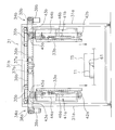
- FIG. 4 is a schematic perspective view of the stacking device.
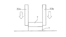
- FIG. 5 is a schematic front view of the stacking device.
- the centering stacking device 11 has a stacking device 31 (an example of a holding device).
- the stacking device 31 is a device for stacking the centered tires T.
- the stacking device 31 has a pair of columns 31a and a ceiling portion 31b that connects the columns 31a to each other at the upper part.
- the pair of columns 31a are arranged on both sides of the first conveyor 5 so as to sandwich the stacking position 61 of the first conveyor 5.
- the stacking device 31 has a first holding portion 33a and a second holding portion 33b.
- the first holding portion 33a and the second holding portion 33b are members for sandwiching the side surfaces of one or a plurality of tires T.
- the first holding portion 33a and the second holding portion 33b have a predetermined length in the vertical direction, and have arc-shaped contact surfaces 33a1 and 33b1 (an example of a bent portion) in a plan view.
- the first holding portion 33a and the second holding portion 33b can hold, for example, one tire T or two to ten stacked tires T at the same time.
- the first holding portion 33a is on the same side as the second positioning device 23. Since the contact surfaces 33a1 and 33b1 are bent portions, the first sandwiching portion 33a and the second sandwiching portion 33b can be brought into contact with each other along the side surface of the tire T.
- the stacking device 31 has a first horizontal driving device 34a and a second horizontal driving device 34b for moving the first holding portion 33a and the second holding portion 33b in the horizontal direction.
- the first horizontal drive device 34a and the second horizontal drive device 34b are the first chain 36a and the second chain that drive the first carriage 35a and the second carriage 35b and the first carriage 35a and the second carriage 35b in the horizontal direction. It has a chain 36b, a first sprocket 37a and a second sprocket 37b, a third sprocket 38a and a fourth sprocket 38b, and a first pinching motor 39a and a second pinching motor 39b, respectively.
- the stacking device 31 has a first elevating device 41a and a second elevating device 41b.
- the first elevating device 41a and the second elevating device 41b are a pair of devices that elevate and lower the first holding portion 33a and the second holding portion 33b, respectively.
- the first elevating device 41a and the second elevating device 41b are provided below each of the first horizontal driving device 34a and the second horizontal driving device 34b.
- the first elevating device 41a connects the first lower sprocket 42a arranged downward in the vertical direction, the first upper sprocket 43a arranged upward in the vertical direction, the first lower sprocket 42a, and the first upper sprocket 43a. It has a first chain 44a to be used.
- a first sandwiching portion 33a is fixed to the first chain 44a.
- the first elevating device 41a further includes a first elevating motor 45a that drives the first upper sprocket 43a and moves the first holding portion 33a between the upper position and the lower position.
- the first elevating device 41a further has a first guide portion 46a that guides the first holding portion 33a in the vertical direction.
- the second elevating device 41b connects the second lower sprocket 42b arranged downward in the vertical direction, the second upper sprocket 43b arranged upward in the vertical direction, the second lower sprocket 42b, and the second upper sprocket 43b. It has a second chain 44b to be used. A second sandwiching portion 33b is fixed to the second chain 44b.
- the second elevating device 41b further has a second elevating motor 45b that drives the second upper sprocket 43b and moves the second holding portion 33b between the upper position and the lower position.
- the second elevating device 41b further has a second guide portion 46b that guides the second holding portion 33b in the vertical direction.
- the above-mentioned "upper position of the first holding portion 33a and the second holding portion 33b” means that the lower ends of the first holding portion 33a and the second holding portion 33b are at a height that does not interfere with one tire T. is doing.
- the upper position may be, for example, an upper position according to the height of the largest tire T, or an upper position according to the type of the tire T.
- the above-mentioned "lower position of the first holding portion 33a and the second holding portion 33b” is the first when the first holding portion 33a and the second holding portion 33b grip the tire T on the first conveyor 5.
- the height is such that the sandwiching portion 33a and the second sandwiching portion 33b and the first conveyor 5 do not interfere with each other.
- the lower ends of the first sandwiching portion 33a and the second sandwiching portion 33b are lower than the first lower sprocket 42a and the second lower sprocket 42b. Is also provided so that it is in a low position. Therefore, the lowermost tire T among the plurality of stages of tires T can also be sandwiched by the first sandwiching portion 33a and the second sandwiching portion 33b. As shown in FIG. 5, the first lower sprocket 42a and the second lower sprocket 42b are provided at positions higher than the upper surface of the highest tire T.
- the first lower sprocket 42a and the second lower sprocket 42b are arranged above the first conveyor 5, but the first lower sprocket 42a and the second lower sprocket 42b hinder the transportation of the tire T. There is no.
- the stacking device 31 has a first sensor 73a and a second sensor 73b (an example of a sensor) (FIGS. 6 and 10).
- the first sensor 73a and the second sensor 73b are sensors that detect the tire T at a predetermined distance from the contact surfaces 33a1 and 33b1 of the first holding portion 33a and the second holding portion 33b, respectively.
- the first sensor 73a and the second sensor 73b are light transmission type sensors, and are composed of floodlights and receivers arranged on the left and right ends of the contact surfaces 33a1 and 33b1 of the first holding portion 33a and the second holding portion 33b, respectively. It is configured.
- the contact surfaces 33a1 and 33b1 are provided with holes (not shown) through which the optical axes of the first sensor 73a and the second sensor 73b pass. Further, the optical axes of the first sensor 73a and the second sensor 73b are orthogonal to the moving directions of the first holding portion 33a and the second holding portion 33b, and the first holding portion 33a and the second holding portion 33a and the second holding portion 33a are viewed in a plan view. It connects the end side and the end side of the arc of the sandwiching portion 33b.
- the optical axis may be parallel to and deviated from the above line, for example, as long as it crosses the arc by intersecting two points of the arc in a plan view and thereby follows the tire T. In this embodiment, the optical axis extends in the horizontal direction.
- the stacking device 31 has a tire height sensor 74 (FIG. 10) for grasping the height of the tire T.
- the tire height sensor 74 is a plurality of light transmitting type or light reflecting type sensors arranged in the height direction.
- the type of sensor is not particularly limited, and a distance measuring sensor arranged above the tire T may be used. Further, the position of the sensor is not particularly limited. Further, the grasp of the height of the tire T may be included in the tire information from the host controller (not shown).
- the controller 71 controls the driving amounts of the first elevating motor 45a and the second elevating motor 45b according to the height of the tire T. Therefore, the amount of rise of the first holding portion 33a and the second holding portion 33b can be minimized, so that the operation efficiency is improved.
- the stacking device 31 has a tire arrival sensor 75 (FIG. 10) that detects that the tire T has arrived at the stacking position 61.
- the tire arrival sensor 75 is a light transmission type or light reflection type sensor provided on both sides of the first conveyor 5.
- the type of sensor is not particularly limited, and a touch sensor provided on the first stopper 15 to detect contact with the tire T may be used.
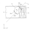
- FIG. 6 is a schematic partial plan view illustrating a holding operation of the stacking device.
- a plurality of types of tires T1 to T5 are shown.
- each tire T is determined by the tire first portion t1 on the end side defined by the first positioning device 13 and the second positioning device 23. It has a tire second portion t2 which is on the end side.
- the position of the first portion t1 of the tire in the first direction is determined by the first stopper 15.
- the position of the second portion t2 of the tire in the second direction is previously determined by the second stopper 25 of the second positioning device 23.
- the tire T does not rotate on the first conveyor 5.
- the portion of the tire T in contact with the second stopper 25 becomes the tire second portion t2 at the stacking position 61 as it is.
- FIG. 6 shows only the tire first portion t1 and the tire second portion t2 of the tire T5.
- the tire T1 will be described as an example with reference to FIGS. 7 to 9.
- 7 to 9 are schematic partial plan views for explaining the pinching operation of the stacking device.
- the tire T1 is the tire with the smallest size (that is, the shortest outer diameter).
- the first pinching portion 33a and the second pinching portion 33b pass between the tire first portion t1 and the tire second portion t2 of the tire T1 to sandwich the side surface of the tire T.
- the first holding portion 33a and the second holding portion 33b are sandwiched obliquely with respect to the first direction in the middle of the straight line P connecting the tire first portion t1 and the tire second portion t2.
- first sandwiching portion 33a and the second sandwiching portion 33b are sandwiched in a third direction (extending direction of the straight line Q, clamping direction) orthogonal to the straight line P in the horizontal direction. More specifically, the first pinching portion 33a and the second pinching portion 33b are between the tire first portion t1 and the tire second portion t2 (specifically, the tire first portion t1 and the tire first portion in the straight line P). Passing between the two portions t2), the tire T1 is sandwiched in a direction inclined by 45 degrees with respect to the first direction.
- the first pinching portion 33a and the second pinching portion 33b can accurately pinch the tires T1 having different outer diameters. Further, the first positioning device 13 and the stacking device 31 can be made into a compact configuration. In this embodiment, the center in the pinching direction and the center of the tire T1 coincide with each other regardless of the type of the tire T. This is because the tire T has a circular shape, so that the center can be determined by performing two-point positioning.
- the tire pinching operation will be described step by step.
- the tire T1 is positioned by the first stopper 15.
- the first holding portion 33a and the second holding portion 33b move to the first position close to the side surface of the tire T1.
- the arrival at the first position is determined by the detection signals from the first sensor 73a and the second sensor 73b.
- the tire T1 can be detected before the first holding portion 33a and the second holding portion 33b come into contact with the tire T1, because the first holding portion 33a and the first holding portion 33a provided with the first sensor 73a and the second sensor 73b can be detected. This is because the 2 sandwiching portion 33b is bent.
- the first pinching portion 33a and the second pinching portion 33b move to the second position where they abut on the side surface of the tire T1, whereby the first pinching portion 33a and the second pinching portion 33b move. Hold the tire T1.
- the detection signals from the first sensor 73a and the second sensor 73b that the first holding portion 33a and the second holding portion 33b sandwich the tire T1.
- the contact surfaces 33a1 and 33b1 of the first sandwiching portion 33a and the second sandwiching portion 33b have an arc shape in a plan view, the tire T is not contacted before the tire T is sandwiched. Can be detected.
- the diameters of the tires T to be sandwiched are different, they can be accurately detected.
- the first sensor 73a and the second sensor 73b are non-contact type, the number of parts of the tire detecting means can be reduced.
- FIG. 10 is a block diagram showing a control configuration of the stacking device.
- the stacking device 31 has a controller 71 (an example of a controller).
- the controller 71 is a computer having a processor (for example, a CPU), a storage device (for example, ROM, RAM, HDD, SSD, etc.) and various interfaces (for example, an A / D converter, a D / A converter, a communication interface, etc.). It is a system.
- the controller 71 performs various control operations by executing a program stored in the storage unit (corresponding to a part or all of the storage area of the storage device).
- the controller 71 may be composed of a single processor, or may be composed of a plurality of independent processors for each control. Some or all of the functions of each element of the controller 71 may be realized as a program that can be executed by the computer system constituting the controller 71. In addition, a part of the function of each element of the controller 71 may be configured by a custom IC.
- the controller 71 includes a first stopper drive unit 17, a first elevating motor 45a, a second elevating motor 45b, a first pinching motor 39a, a second pinching motor 39b, a first sensor 73a, a second sensor 73b, and a tire height sensor. 74, the tire arrival sensor 75 is connected. Although not shown, the controller 71 is connected to a sensor for detecting the size, shape and position of the tire T, a sensor and a switch for detecting the state of each device, and an information input device.
- FIG. 11 is a flowchart showing the stacking control operation.
- FIG. 12 is a flowchart showing the pinching operation.
- 13 to 25 are schematic views showing one state of the operation of the pair of sandwiching portions in the stacking operation.
- the control flowchart described below is an example, and each step can be omitted or replaced as needed. Further, a plurality of steps may be executed at the same time, or some or all of them may be executed in an overlapping manner. Further, each step of the control flowchart is not limited to a single control operation, and can be replaced with a plurality of control operations represented by a plurality of steps.
- each device is the result of a command from the controller 71 to each device, and these are represented by each step of the software application.
- tires T of the same size (type) are stacked, and after the series of operations is completed, tires of different sizes (types) are stacked.
- the tire T is positioned in the second direction by the second positioning device 23.
- step S1 of FIG. 11 the first stopper 15 moves to the contact position.
- the controller 71 controls the first stopper drive unit 17 to execute the above operation.
- step S2 the tire T waits for the stacking position 61 to arrive.
- the controller 71 determines the arrival of the tire T based on the detection signal from the tire arrival sensor 75.
- the process proceeds to step S3.
- step S3 the first stopper 15 moves to the retracted position. Specifically, the controller 71 controls the first stopper drive unit 17 to execute the above operation.
- step S4 the pinching operation in which the first pinching portion 33a and the second pinching portion 33b sandwich the tire T is executed.
- the operation of the first holding portion 33a will be described with reference to FIG. 12 (the same applies to the second holding portion 33b).
- step S101 the first holding portion 33a moves to the tire T side.
- step S102 it is determined whether or not the first sensor 73a has detected the tire T. If detected (if the detection signal is received from the first sensor 73a), the process proceeds to step S103, and if not detected, the process returns to step S101.
- step S103 as shown in FIG.
- step S104 the first pinching portion 33a stops at the first position close to (that is, not pinching) the side surface of the tire T.
- the condition for shifting from step S103 to step S104 includes checking the state of the second pinching portion 33b in order to prevent the tire T from being pushed during pinching.
- step S104 the first holding portion 33a further moves to the tire T side.
- the first holding portion 33a moves to the second position where it abuts on the side surface of the tire T.
- step S105 it is determined whether or not the torque value of the first pinching motor 39a has reached the specified value. If the specified value is reached, the process proceeds to step S106, and if the specified value is not reached, the process returns to step 104.
- step S106 the movement of the first holding portion 33a is stopped.
- step S5 of FIG. 11 it waits for the pinching operation to end.
- the controller 71 determines the end of the pinching operation based on, for example, the torques of the first pinching motor 39a and the second pinching motor 39b.
- step S6 as shown in FIG. 17, the first holding portion 33a and the second holding portion 33b are raised to lift the tire T.
- the controller 71 controls the first elevating motor 45a and the second elevating motor 45b to execute the above operation.
- step S7 the first stopper 15 moves to the contact position.
- step S8 it waits for the next tire T to arrive at the stacking position 61.
- the controller 71 determines the arrival of the tire T based on the detection signal from the tire arrival sensor 75.
- step S9 the first stopper 15 moves to the retracted position.
- step S10 as shown in FIG. 19, the first pinching portion 33a and the second pinching portion 33b are lowered to load and unload the gripped tire T onto the lower tire T.
- the controller 71 controls the first elevating motor 45a and the second elevating motor 45b to execute the above operation.
- step S11 the first pinching portion 33a and the second pinching portion 33b are separated from the tire T laterally to release the pinching.
- the controller 71 controls the first pinching motor 39a and the second pinching motor 39b to execute the above operation.
- the amount of movement of the first holding portion 33a and the second holding portion 33b may be controlled by a timer.
- the first holding portion 33a and the second holding portion 33b can be separated by the same distance or different distances.
- step S12 it is determined whether or not the stacking operation is completed. If it ends, the process ends, and if it does not end, the process returns to step S4. After the process is completed, the tires T on which the first conveyor 5 is stacked are transported to the downstream side in the transport direction.
- Steps S4 to S11 are repeated a predetermined number of times.
- step S4 as shown in FIGS. 21 to 23
- the pinching operation of the tire T is executed.
- the detection signals from the first sensor 73a and the second sensor 73b are used only for confirming the presence of the tire T (described later).
- step S6 the operation of lifting the tire T is executed as shown in FIG. 24.
- step S8 as shown in FIG. 25, it waits for the next tire T to arrive.
- description thereof will be omitted.
- the position of the tire T in the first direction is determined by the first positioning device 13, and the position in the second direction is determined by the second positioning device 23.
- the tire T is further sandwiched between the tire first portion t1 and the tire second portion t2 by the first sandwiching portion 33a and the second sandwiching portion 33b. In this way, even tires T having different outer diameters are accurately sandwiched.
- the controller may move the first pinching portion 33a and the second pinching portion 33b to the second position without stopping at the first position to sandwich the tire T. .. This is because, for example, for the tire T that is first carried in with the space between the first holding portion 33a and the second holding portion 33b empty, the first holding portion 33a and the second holding portion 33b are brought closer to the first position. This is because the tires are moved to the tire and stopped at the first position, so that the position and the pinching position can be memorized and the amount of movement to the second position can be determined.
- the tire T is operated by the first sensor 73a and the second sensor 73b. Make sure that is pinched. In this device, the second and subsequent tires T do not stop at the first position, so that the cycle time is shortened.
- the first sensor 73a and the second sensor 73b are used for stopping the first tire T1 at the first position of the first pinching portion 33a and the second pinching portion 33b, and the second and subsequent tires T1.
- the tire T is used to confirm that the first holding portion 33a and the second holding portion 33b sandwich the tire T at the second position.
- the above control can be used in stacking and disassembling.
- the tire T carried in first is the first baggage
- the tire T carried in after the second is the second baggage.
- step disassembly the bottom tire T of the stacked tires T is the first luggage
- the second and subsequent tires T of the stacked tires are the second luggage. ..
- the stacked tires T are collectively transported by, for example, a transport device that supports the inner diameter or the lower side of the tire T.
- the stacked tires T are closer to one side in the second direction, but the center of the tires is aligned with the transfer position by the same mechanism as the second direction adjusting conveyor.
- the transport device can support the tire T in a fixed position.
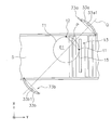
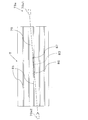
- FIG. 26 is a schematic side view showing the relationship between the tire and the optical axis of the sensor in the second embodiment. Since the basic configuration and the basic operation are the same as those in the first embodiment, the differences will be mainly described below. Further, since the first sensor 73a and the second sensor 73b have the same configuration, only the first sensor 73a will be described.
- the first sensor 73a is a sensor that detects the tire T at a predetermined distance from the contact surfaces of the first holding portion 33a and the second holding portion 33b.
- the optical axis 76 of the first sensor 73a is set to be tilted upward with respect to the horizontal direction.
- the floodlight 73a1 is provided on the upper side and the light receiver 73a2 is provided on the lower side.
- the tilt angle of the optical axis 76 is, for example, about 5 degrees. With the above angle, transmission through the groove 81 (described later) of the tire T is prevented, that is, the large outer surface of the tire T can be reliably detected.
- the tire T shown in FIG. 26 has a plurality of grooves 81 extending in the circumferential direction.
- the detection portion 83 of the pinching direction apex of the tire T is a portion detected by the sensor, and in the present embodiment, the portions 85 and 87 within the detection portion 83 and on both sides are detected. It is supposed to be done.
- the controller confirms the detection of the tire T by the sensor after the pair of sandwiching portions has stopped at the first position.
- the controller may confirm the detection of the tire T by the sensor without stopping the pair of holding portions at the first position. In this case, if the detection of the tire T cannot be confirmed, the pair of sandwiching portions are stopped after passing through the first position.
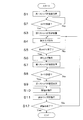
- FIG. 27 is a flowchart showing the pinching operation in the third embodiment.
- step S101 the first holding portion 33a moves to the tire T side.
- step S102 it is determined whether or not the first sensor 73a has detected the tire T. If detected, the process proceeds to step S105, and if not detected, the process proceeds to step S107.
- the condition for shifting from step S102 to step S105 includes checking the state of the second pinching portion 33b in order to prevent the tire T from being pushed during pinching. As a result, the first holding portion 33a moves to the second position where it abuts on the side surface of the tire T.
- step S105 it is determined whether or not the torque value of the first pinching motor 39a has reached the specified value. If the specified value is reached, the process proceeds to step S106, and if the specified value is not reached, the process executes step S105 again.
- step S106 the movement of the first holding portion 33a is stopped.
- step S107 it is determined whether or not the amount of movement of the first holding portion 33a exceeds a predetermined distance. If the predetermined distance is exceeded, the process proceeds to step S108, and if the predetermined distance is not exceeded, the process returns to step S101. In step S108, the movement of the first sandwiching portion 33a is stopped, and an abnormality process is further performed.
- the above-mentioned “predetermined distance” is determined for each tire T, for example. More specifically, the “predetermined distance” means that the distance between the first holding portion 33a and the second holding portion 33b is the same as or smaller than the width at which the tire T can be detected without contact, or the same as the diameter of the tire T. Or it is set to be smaller.
- the sandwiching device (for example, the stacking device 31) includes a mounting portion, a pair of sandwiching portions, a sensor, and a controller.
- a round load (for example, a tire T) is placed on the mounting portion (for example, the transport surface 5a).
- the pair of holding portions (for example, the first holding portion 33a and the second holding portion 33b) sandwich the side surface of the load to be placed on the mounting portion, and can come into contact with the side surface of the load including the bent portion.
- Has a contact surface for example, contact surfaces 33a1, 33b1).
- the sensors eg, first sensor 73a and second sensor 73b) have an optical axis that traverses the bend and is along the load.
- the controller moves the pair of holding portions close to the first position (for example, FIG. 8) that does not hold the load, and when the sensor detects the load, the second position for holding the load. (For example, FIG. 9) is moved so that the pair of holding portions are close to each other.
- the pair of holding portions since the pair of holding portions have the bent portion and the luggage is round, the luggage can be detected by non-contact before the luggage is sandwiched. Therefore, even if the diameters of the luggage to be carried are different, it can be detected accurately.
- the sensor is a non-contact type, the number of parts of the tire detecting means can be reduced.
- the controller moves a pair of holding parts toward the tire at the same time.
- the controller may make the timing of movement of the pair of holding portions different.
- the tire may be sandwiched by first bringing one sandwiching portion into contact with the tire and then bringing the other sandwiching portion into contact with the tire.
- the holding device may be used for a device other than the stacking device.
- the present invention can be applied not only to stacking but also to stacking. For example, positioning may be performed in the same manner as in stacking, and step disassembling may be performed.
- Deformation example of luggage Round luggage is not limited to tires.
- the present invention can be widely applied to a holding device for holding a round load.
- Conveyor system 3 Conveyor device 5: 1st conveyor 5a: Conveyor surface 7: 2nd conveyor 9: Conversion machine 11: Centering stacking device 13: 1st positioning device 15: 1st stopper 17: 1st stopper drive unit 23: Second positioning device 25: Second stopper 31: Stacking device 31a: Pillar 31b: Ceiling portion 33a: First holding portion 33b: Second holding portion 34a: First horizontal driving device 34b: Second horizontal driving Device 35a: 1st sprocket 35b: 2nd trolley 36a: 1st chain 36b: 2nd chain 37a: 1st sprocket 37b: 2nd sprocket 38a: 3rd sprocket 38b: 4th sprocket 39a: 1st pinching motor 39b: 1st 2 Holding motor 41a: 1st elevating device 41b: 2nd elevating device 42a: 1st lower sprocket 42b: 2nd lower sprocket 43a: 1
Landscapes
- Engineering & Computer Science (AREA)
- Mechanical Engineering (AREA)
- Automation & Control Theory (AREA)
- Civil Engineering (AREA)
- Structural Engineering (AREA)
- Tyre Moulding (AREA)
- Load-Engaging Elements For Cranes (AREA)
- Automobile Manufacture Line, Endless Track Vehicle, Trailer (AREA)
- Stacking Of Articles And Auxiliary Devices (AREA)
Abstract
Description
特許文献1に記載の天井走行車に組み込まれたタイヤ挟持装置は、昇降台と、チャッキング爪と、チャックキング爪に設けられたセンサとを有している。この天井走行車では、チャッキング爪は、タイヤの内側に配置されて、タイヤを内側から支持する。 Conventionally, a tire holding device for holding and moving a tire is known (see, for example, Patent Document 1).
The tire holding device incorporated in the ceiling traveling vehicle described in
そのような検出手段では、機械式であるので、部品点数が多くなっていた。 In the conventional tire holding device, it is necessary to detect the position of the tire when the tire is gripped by the hand. Conventionally, as such a detection means, a mechanical type including a detection plate, a spring, and a detection plate detector has been adopted.
Since such a detection means is mechanical, the number of parts is large.
載置部は、丸型の荷物を載置する。
一対の挟持部は、載置部に載置される荷物の側面を挟持するものであり、屈曲部を含み荷物の側面に当接可能な当接面を有する。
センサは、屈曲部を横断し、荷物に沿う方向に光軸を有する。
コントローラは、荷物を挟持しないがセンサにより荷物が検出される第1位置まで一対の挟持部を近づくように移動させ、センサからの検出信号を受け取り、次に荷物を挟持する第2位置まで一対の挟持部を互いに近づくように移動させる。
なお、屈曲部の形状は、例えば、平面視で円弧又はV字形状の一部でもよい。例えば、屈曲部は、円弧であれば弧の部分、V字形状であれば曲がっている部分である。
屈曲部があることで、丸型の荷物の側面に沿って一対の挟持部が当接でき、さらに、荷物に対して当接面が接触する前に荷物を検知できる。
なお、コントローラは、一対の挟持部が第1位置で停止させてからセンサによる荷物の検出を確認してもよい。また、コントローラは、一対の挟持部を第1位置で停止させずに、センサによる荷物の検出を確認してもよい。この場合は、一対の挟持部の移動は、荷物の検出が確認できなければ、第1位置を通過後に終了される。
この装置では、一対の挟持部の当接面が屈曲部を有しており、かつ荷物が丸型であるので、荷物を挟持する前に、非接触によって荷物を検知できる。したがって、挟持する荷物の径が異なっていても、正確に検知できる。
この装置では、センサが非接触式であるので、部品数が少なくなる。 The sandwiching device according to the seemingly present invention includes a mounting portion, a pair of sandwiching portions, a sensor, and a controller.
The loading section stores round luggage.
The pair of holding portions sandwiches the side surface of the load to be placed on the loading portion, and has a contact surface that can come into contact with the side surface of the load including the bent portion.
The sensor has an optical axis across the bend and along the load.
The controller does not pinch the cargo, but moves the pair of pinching parts closer to the first position where the cargo is detected by the sensor, receives the detection signal from the sensor, and then pairs to the second position where the cargo is pinched. Move the sandwiches so that they are close to each other.
The shape of the bent portion may be, for example, a part of an arc or a V shape in a plan view. For example, the bent portion is an arc portion if it is an arc, and a curved portion if it is V-shaped.
The presence of the bent portion allows the pair of holding portions to come into contact with the side surface of the round load, and further, the load can be detected before the contact surface comes into contact with the load.
The controller may confirm the detection of the load by the sensor after the pair of holding portions is stopped at the first position. Further, the controller may confirm the detection of the load by the sensor without stopping the pair of holding portions at the first position. In this case, the movement of the pair of holding portions is terminated after passing through the first position if the detection of the cargo cannot be confirmed.
In this device, since the contact surface of the pair of holding portions has a bent portion and the luggage is round, the luggage can be detected by non-contact before the luggage is sandwiched. Therefore, even if the diameters of the luggage to be carried are different, it can be detected accurately.
In this device, since the sensor is non-contact type, the number of parts is reduced.
センサは、光軸が円弧の2点と交わるように設けられていてもよい。
なお、光軸は、円弧の端部と端部を結ぶ線に平行であってもよく、円弧の端部と端部を結ぶ線に一致していてもよい。
この装置では、一対の挟持部の当接面が円弧状であり、かつ荷物が丸型であるので、荷物を挟持する前に、非接触によって荷物を検知できる。したがって、挟持する荷物の径が異なっていても、正確に検知できる。
この装置では、センサが非接触式であるので、部品数が少なくなる。 The contact surface is arcuate in plan view
The sensor may be provided so that the optical axis intersects two points of the arc.
The optical axis may be parallel to the line connecting the ends of the arc, or may coincide with the line connecting the ends of the arc.
In this device, since the contact surfaces of the pair of holding portions are arcuate and the luggage is round, the luggage can be detected by non-contact before the luggage is sandwiched. Therefore, even if the diameters of the luggage to be carried are different, it can be detected accurately.
In this device, since the sensor is non-contact type, the number of parts is reduced.
光軸は、平面視で、第1挟持部及び第2挟持部の円弧の端部側と端部側を結んでいてもよい。
この装置では、当接面から離れた位置で荷物を非接触により検知できるので、荷物を確実に検知できる。 The optical axis may be orthogonal to the moving direction of the pair of sandwiching portions.
The optical axis may connect the end side and the end side of the arc of the first holding portion and the second holding portion in a plan view.
In this device, the load can be detected non-contactly at a position away from the contact surface, so that the load can be reliably detected.
センサは、光軸が水平方向に対して上方向に傾くように設けられていてもよい。
この装置では、光軸が斜めであるので、光軸がタイヤの溝内に入り込んでしまうという不具合が生じにくい。その結果、タイヤを正確に検知できる。
なお、「水平方向に延びる溝」は、全体として水平方向に延びていればよく、例えば、直線、ジグザグを含む。
コントローラは、センサにより荷物が検出されると、一対の挟持部のうち当該センサが設けられている挟持部の移動を停止してもよい。
コントローラは、
センサにより荷物が検出されても、一対の挟持部のうち当該センサが設けられている挟持部の移動を続行し、
一対の挟持部のうちの一方の移動距離が所定距離を超えてもセンサにより荷物が検出されなければ、当該挟持部の移動を停止して、異常処理してもよい。 The luggage may be a tire having laterally grooved sides.
The sensor may be provided so that the optical axis is tilted upward with respect to the horizontal direction.
In this device, since the optical axis is slanted, the problem that the optical axis gets into the groove of the tire is unlikely to occur. As a result, the tire can be detected accurately.
The "groove extending in the horizontal direction" may extend in the horizontal direction as a whole, and includes, for example, a straight line and a zigzag.
When the load is detected by the sensor, the controller may stop the movement of the holding portion provided with the sensor among the pair of holding portions.
The controller is
Even if the cargo is detected by the sensor, the movement of the holding part of the pair of holding parts provided with the sensor is continued, and the movement is continued.
If the sensor does not detect the cargo even if the moving distance of one of the pair of holding parts exceeds a predetermined distance, the movement of the holding parts may be stopped to handle the abnormality.
コントローラは、2番目以降に挟持される第二荷物については、一対の挟持部を第1位置で停止させずに第2位置まで移動させて第二荷物を挟持してもよい。
コントローラは、第二荷物に対して一対の挟持部が第2位置で停止した後、センサによって荷物が挟持されていることを確認してもよい。
この装置では、2番目以降に搬入される第二荷物は第1位置で停止しないので、サイクルタイムが短縮される。
第二荷物を第1位置で停止しなくてよい理由は、例えば、第一荷物については、一対の挟持部を互いに近づくように移動させて第1位置で停止させているので、その位置を記憶することで一対の挟持部の第2位置までの移動量を決定できるからである。
また、センサは、第一荷物については一対の挟持部の第1位置への停止のために用いられ、第二荷物については一対の挟持部が第2位置で第二荷物を挟んでいることを確認するために用いられる。
本発明の他の見地に係る段積み装置は、前述の挟持装置と、一対の挟持部を水平方向及び上下方向に駆動する駆動装置と、を備えている。 The controller is carried in with an empty space between the pair of holding portions, and for the first luggage to be held first, the pair of holding portions are moved so as to approach the first position and stopped at the first position. When the first load is detected by the sensor, the pair of holding portions may be moved so as to approach each other to the second position where the first load is held.
For the second luggage to be held after the second, the controller may move the pair of holding portions to the second position without stopping at the first position to hold the second luggage.
The controller may confirm that the luggage is being held by the sensor after the pair of holding portions with respect to the second luggage is stopped at the second position.
In this device, the second and subsequent packages are not stopped at the first position, so that the cycle time is shortened.
The reason why the second baggage does not have to be stopped at the first position is, for example, for the first baggage, since the pair of holding portions are moved closer to each other and stopped at the first position, the position is memorized. This is because the amount of movement of the pair of sandwiching portions to the second position can be determined.
Further, the sensor is used for stopping the pair of holding portions at the first position for the first luggage, and for the second luggage, the pair of holding portions sandwich the second luggage at the second position. Used to confirm.
The stacking device according to another aspect of the present invention includes the above-mentioned sandwiching device and a driving device for driving a pair of sandwiching portions in the horizontal direction and the vertical direction.
(1)搬送システム全体
図1を用いて、第1実施形態の搬送システム1を説明する。図1は、第1実施形態の搬送システムの模式的平面図である。
搬送システム1は、タイヤT(荷物の一例)を1個ずつ搬送し、次に複数のタイヤTを段積みし、さらに段積みされたタイヤTを搬送する機能を有している。 1. 1. First Embodiment (1) Overall Transfer System The
The
搬送システム1は、コンベヤ装置3を有している。コンベヤ装置3は、タイヤTを搬送する装置である。搬送されるタイヤTは、大きさの異なる複数種類がある。
コンベヤ装置3は、主に、第1コンベヤ5と、第2コンベヤ7と、転換機9とを備えている。転換機9は、第1コンベヤ5と第2コンベヤ7との間に配置されている。タイヤTは、第2コンベヤ7、転換機9、第1コンベヤ5の順番で搬送される。
第1コンベヤ5と第2コンベヤ7は直交しており、転換機9がタイヤTを第2コンベヤ7から第1コンベヤ5へと搬送方向を変える。
第1コンベヤ5及び第2コンベヤ7は、公知の技術であり、例えばローラコンベヤであり、タイヤTを搬送する搬送面5aを有する。転換機9は、公知の技術であり、例えばローラコンベヤとその間を昇降可能なチェーンコンベヤとからなる。なお、各装置の部材は図の簡略化のため適宜省略されている。
なお、以下、第1コンベヤ5の延びる方向を第1方向(矢印Y)とし、第2コンベヤ7の延びる方向を第2方向(矢印X)とする。 (2) Conveyor device The
The
The
The
Hereinafter, the extending direction of the
搬送システム1は、センタリング段積み装置11を有している。センタリング段積み装置11は、タイヤTをセンタリングしながら段積みする装置である。段積みされたタイヤTはその後にロボットアーム(図示せず)等を用いて直接ラック(図示せず)に挿入されるが、タイヤT同士が正確にセンタリングされていなければ、ロボットアームが複数のタイヤTを把持するときにタイヤが傾いて崩れてしまうおそれがある。そこで、正確なセンタリングが必要である。センタリング段積み装置11は、上記の問題を解消することを目的としている(後述)。 (3) Centering Stacking Device The
センタリング段積み装置11は、第1位置決め装置13を有している。第1位置決め装置13は、第1コンベヤ5により搬送されるタイヤTの端部を第1方向における第1所定位置に定める装置である。
第1位置決め装置13は、第1ストッパ15を有している。第1ストッパ15は、第1コンベヤ5に設けられている。第1ストッパ15は、第1コンベヤ5の搬送面5a(載置部の一例)の上方に突出して、第1コンベヤ5により搬送されるタイヤTと第1方向に当接可能である。第1ストッパ15は、第2方向に延在している。
図2及び図3を用いて、第1位置決め装置13を具体的に説明する。図2及び図3は、第1位置決め装置の模式的側面図である。
第1位置決め装置13は、第1ストッパ15を、搬送面5aから上方に突出する当接位置(図2)と、当接位置よりタイヤTから搬送方向下流側の斜め下方に離れて搬送面5aより下方にある退避位置(図3)との間で移動させる第1ストッパ駆動部17を有している。第1ストッパ駆動部17は、例えば、エアシリンダである。
この搬送システム1では、第1ストッパ15は、タイヤTが当接した後に、当接位置から退避位置に移動する。このとき、退避位置が当接位置よりタイヤTから第1方向に離れた位置にあるので、第1ストッパ15からタイヤTに荷重が作用しにくい。したがって、タイヤTの位置や向きが変わりにくい。なお、タイヤTの回転やすり減りを考慮しなければ、第1ストッパは上下のみの出退でもよい。 (3-1) First Positioning Device The centering stacking
The
The
The
In this
センタリング段積み装置11は、第2位置決め装置23を有している。第2位置決め装置23は、第2方向におけるタイヤTの端部を第2所定位置に定める装置である。
第2位置決め装置23は、第2ストッパ25を有している。第2ストッパ25は、転換機9において、第2方向の片側(図1の下側)に設けられている。第2ストッパ25は、転換機9の搬送面9aの上方に突出してタイヤTの一方の側面に当接可能である。
第2位置決め装置23は、第2ストッパ25を、搬送面5aから上方に突出する当接位置と、当接位置よりタイヤTから第2方向に離れた退避位置との間で移動させる駆動部77(図10)を有している。駆動部77は、第1位置決め装置13の第1ストッパ駆動部17と同じでもよく、又は、第2ストッパ25を横方向に退避させる構造でもよい。なお、タイヤTの回転を考慮しない場合は、第2ストッパ25は退避しなくてもよい。 (3-2) Second Positioning Device The centering stacking
The
The
その後、第2ストッパ25は当接位置から退避位置に移動する。このとき、当接位置が退避位置よりタイヤTから第2方向に離れた位置にあるので、第2ストッパ25からタイヤTに荷重が作用しにくい。したがって、タイヤTの位置や向きが変わりにくい。
さらにその後にタイヤTは第1コンベヤ5上で第1方向において第1位置決め装置13に向かって搬送される。このとき、第1コンベヤ5の第2方向奥側(図1下側)にはガイドが設けられていないので、タイヤTは第2方向において位置決めされた姿勢や位置が変更されることなく、搬送される。
そして、タイヤTは、段積み位置61において、第1ストッパ15によって第1方向に位置決めされる。段積み位置61とは、第1ストッパ15の搬送方向上流側において、タイヤTが停止されて占有する位置である。以上より、タイヤTは、第1方向と第2方向にそれぞれ位置決めされた状態で、第1ストッパ15によって第1コンベヤ5上の段積み位置61で停止する。 The converter 9 brings the tire T closer to one side in the second direction (lower side in FIG. 1 and the
After that, the
After that, the tire T is conveyed on the
Then, the tire T is positioned in the first direction by the
図4及び図5を用いて、段積み装置を説明する。図4は、段積み装置の模式的斜視図である。図5は、段積み装置の模式的正面図である。
センタリング段積み装置11は、段積み装置31(挟持装置の一例)を有している。段積み装置31は、センタリングされたタイヤTを段積みするための装置である。
段積み装置31は、一対の柱31aと、柱31a同士を上部で連結する天井部31bとを有している。一対の柱31aは第1コンベヤ5の両側で、かつ、第1コンベヤ5の段積み位置61を挟むように配置されている。 (3-3) Stacking device The stacking device will be described with reference to FIGS. 4 and 5. FIG. 4 is a schematic perspective view of the stacking device. FIG. 5 is a schematic front view of the stacking device.
The centering stacking
The stacking
第1昇降装置41aは、上下方向において下方に配置される第1下部スプロケット42aと、上下方向において上方に配置される第1上部スプロケット43aと、第1下部スプロケット42aと第1上部スプロケット43aを連結する第1チェーン44aとを有している。第1チェーン44aには、第1挟持部33aが固定されている。第1昇降装置41aは、さらに、第1上部スプロケット43aを駆動させ、第1挟持部33aを上方位置と下方位置との間で移動させる第1昇降モータ45aを有している。第1昇降装置41aは、さらに、第1挟持部33aを上下方向にガイドする第1ガイド部46aを有している。 The stacking
The first elevating
なお、上記の「第1挟持部33a及び第2挟持部33bの上方位置」は、第1挟持部33a及び第2挟持部33bの下端がタイヤT1つ分と干渉しない高さにあることを意味している。上方位置としては例えば、最も大きいタイヤTの高さに合わせた上方の位置でもよいし、タイヤTの種類に合わせた上方の位置でもよい。
さらに、上記の「第1挟持部33a及び第2挟持部33bの下方位置」は、第1挟持部33a及び第2挟持部33bが第1コンベヤ5上のタイヤTを把持した際に、第1挟持部33a及び第2挟持部33bと第1コンベヤ5が干渉しない高さである。 The second elevating
The above-mentioned "upper position of the
Further, the above-mentioned "lower position of the
図5に示すように、第1下部スプロケット42a及び第2下部スプロケット42bは、最も高いタイヤTの上面より高い位置に設けられている。そのため、この実施形態では第1下部スプロケット42a及び第2下部スプロケット42bが第1コンベヤ5の上方に配置されているが、第1下部スプロケット42a及び第2下部スプロケット42bがタイヤTの搬送を妨げることがない。 As shown in FIG. 5, in the
As shown in FIG. 5, the first
第1センサ73a及び第2センサ73bは、光透過型センサであり、それぞれ第1挟持部33a及び第2挟持部33bの当接面33a1、33b1の左右両端に配置された投光器と受光器とから構成されている。なお、当接面33a1、33b1には、第1センサ73a及び第2センサ73bの光軸が通る穴(図示せず)が設けられている。
また、第1センサ73a及び第2センサ73bの光軸は、第1挟持部33a及び第2挟持部33bの移動方向に対して直交しており、平面視で、第1挟持部33a及び第2挟持部33bの円弧の端部側と端部側を結んでいる。ただし、光軸は、平面視で円弧の2点と交わることで円弧を横断し、それによりタイヤTに沿う方向であればよいので、例えば、上記の線と平行でかつずれていてもよい。
なお、この実施形態では、光軸は水平方向に延びている。 The stacking
The
Further, the optical axes of the
In this embodiment, the optical axis extends in the horizontal direction.
コントローラ71は、タイヤTの高さに応じて第1昇降モータ45a及び第2昇降モータ45bの駆動量を制御する。このため、第1挟持部33a及び第2挟持部33bの上昇量を最低限にできるので、動作効率が良くなる。
段積み装置31は、タイヤTが段積み位置61に到着したことを検出するタイヤ到着センサ75(図10)を有している。タイヤ到着センサ75は、第1コンベヤ5の両側に設けられた光透過型又は光反射型センサである。なお、センサの種類は特に限定されておらず、第1ストッパ15に設けられてタイヤTとの接触を検出するタッチセンサでもよい。 The stacking
The
The stacking
図6を用いて、段積み装置31の第1挟持部33a及び第2挟持部33bによるタイヤTの挟持動作を説明する。図6は、段積み装置の挟持動作を説明する模式的部分平面図である。
図6では、複数の種類のタイヤT1~T5が示されている。いずれのタイヤTも、第1位置決め装置13の第1ストッパ15に当接した後に、第1位置決め装置13により定められた端部側であるタイヤ第1部分t1と、第2位置決め装置23により定められた端部側であるタイヤ第2部分t2とを有している。タイヤ第1部分t1の第1方向位置は、第1ストッパ15によって位置が定まる。タイヤ第2部分t2の第2方向位置は、第2位置決め装置23の第2ストッパ25によって位置が先に定められている。特に、この実施形態では、タイヤTが第1コンベヤ5において回転しないことを想定している。この場合はタイヤTの第2ストッパ25と当接した部分がそのまま段積み位置61におけるタイヤ第2部分t2になっている。なお、図6では、タイヤT5のタイヤ第1部分t1とタイヤ第2部分t2のみを示している。 (3-4) Tire pinching operation by the first pinching portion and the second pinching portion The pinching operation of the tire T by the
In FIG. 6, a plurality of types of tires T1 to T5 are shown. After contacting the
第1挟持部33a及び第2挟持部33bは、タイヤT1のタイヤ第1部分t1とタイヤ第2部分t2との間を通過することで、タイヤTの側面を挟持する。具体的には、第1挟持部33a及び第2挟持部33bは、タイヤ第1部分t1とタイヤ第2部分t2とを結ぶ直線Pの中間において、第1方向に対して斜めに挟持する。より具体的には、第1挟持部33a及び第2挟持部33bは、該直線Pと水平方向に直交する第3方向(直線Qの伸びる方向、クランプ方向)に挟持する。さらに具体的には、第1挟持部33a及び第2挟持部33bは、タイヤ第1部分t1とタイヤ第2部分t2との間(具体的には、直線Pにおけるタイヤ第1部分t1とタイヤ第2部分t2の間)を通過し、第1方向に対して45度傾く方向にタイヤT1を挟持する。このように挟持方向中心とタイヤT1の中心が一致するので、第1挟持部33a及び第2挟持部33bが、異なる外径のタイヤT1を正確に挟持できる。また、第1位置決め装置13と段積み装置31をコンパクトな構成にできる。
この実施形態では、タイヤTの種類に関わらず挟持方向中心とタイヤT1の中心が一致する。なぜなら、タイヤTが円形であるため、2点位置決めを行えば中心を定めることができるからである。 The tire T1 will be described as an example with reference to FIGS. 7 to 9. 7 to 9 are schematic partial plan views for explaining the pinching operation of the stacking device. The tire T1 is the tire with the smallest size (that is, the shortest outer diameter).
The
In this embodiment, the center in the pinching direction and the center of the tire T1 coincide with each other regardless of the type of the tire T. This is because the tire T has a circular shape, so that the center can be determined by performing two-point positioning.
最初に、図7に示すように、タイヤT1が第1ストッパ15によって位置決めされる。
次に、図8に示すように、第1挟持部33a及び第2挟持部33bが、タイヤT1の側面に近接する第1位置に移動する。第1位置に到達したことは、第1センサ73a及び第2センサ73bからの検出信号によって判断される。このように第1挟持部33a及び第2挟持部33bがタイヤT1に当接する前にタイヤT1を検出できるのは、第1センサ73a及び第2センサ73bが設けられた第1挟持部33a及び第2挟持部33bが屈曲しているからである。 Next, the tire pinching operation will be described step by step.
First, as shown in FIG. 7, the tire T1 is positioned by the
Next, as shown in FIG. 8, the
この段積み装置31では、第1挟持部33a及び第2挟持部33bの当接面33a1、33b1が平面視で円弧形状を有しているので、タイヤTを挟持する前に非接触によってタイヤTを検知できる。したがって、挟持するタイヤTの径が異なっていても、正確に検知できる。
この段積み装置31では、第1センサ73a及び第2センサ73bが非接触式であるので、タイヤ検出手段の部品点数を減らせる。 Finally, as shown in FIG. 9, the
In this stacking
In this stacking
図10を用いて、段積み装置31の制御構成を説明する。図10は、段積み装置の制御構成を示すブロック図である。
段積み装置31は、コントローラ71(コントローラの一例)を有している。コントローラ71は、プロセッサ(例えば、CPU)と、記憶装置(例えば、ROM、RAM、HDD、SSDなど)と、各種インターフェース(例えば、A/Dコンバータ、D/Aコンバータ、通信インターフェースなど)を有するコンピュータシステムである。コントローラ71は、記憶部(記憶装置の記憶領域の一部又は全部に対応)に保存されたプログラムを実行することで、各種制御動作を行う。 (4) Control Configuration of Stacking Device The control configuration of the stacking
The stacking
コントローラ71の各要素の機能は、一部又は全てが、コントローラ71を構成するコンピュータシステムにて実行可能なプログラムとして実現されてもよい。その他、コントローラ71の各要素の機能の一部は、カスタムICにより構成されていてもよい。 The
Some or all of the functions of each element of the
コントローラ71には、図示しないが、タイヤTの大きさ、形状及び位置検出するセンサ、各装置の状態を検出するためのセンサ及びスイッチ、並びに情報入力装置が接続されている。 The
Although not shown, the
図11~図25を用いて、段積み制御動作を説明する。図11は、段積み制御動作を示すフローチャートである。図12は、挟みつけ動作を示すフローチャートである。図13~図25は、段積み動作における一対の挟持部の動作の一状態を示す模式図である。
以下に説明する制御フローチャートは例示であって、各ステップは必要に応じて省略及び入れ替え可能である。また、複数のステップが同時に実行されたり、一部又は全てが重なって実行されたりしてもよい。
さらに、制御フローチャートの各ステップは、単一の制御動作とは限らず、複数のステップで表現される複数の制御動作に置き換えることができる。
なお、各装置の動作は、コントローラ71から各装置への指令の結果であり、これらはソフトウェア・アプリケーションの各ステップによって表現される。
下記に述べる段積み制御動作中の一連の動作時は、同じ大きさ(種類)のタイヤTを段積みし、一連の動作が終了後、異なる大きさ(種類)のタイヤを段積みする。ただし、必ずしも一連の動作毎に大きさ(種類)を変えなくてもよい。
また、下記の動作の前には、タイヤTは、第2位置決め装置23によって第2方向に位置決めがされている。 (5) Stacking control operation The stacking control operation will be described with reference to FIGS. 11 to 25. FIG. 11 is a flowchart showing the stacking control operation. FIG. 12 is a flowchart showing the pinching operation. 13 to 25 are schematic views showing one state of the operation of the pair of sandwiching portions in the stacking operation.
The control flowchart described below is an example, and each step can be omitted or replaced as needed. Further, a plurality of steps may be executed at the same time, or some or all of them may be executed in an overlapping manner.
Further, each step of the control flowchart is not limited to a single control operation, and can be replaced with a plurality of control operations represented by a plurality of steps.
The operation of each device is the result of a command from the
During a series of operations during the stacking control operation described below, tires T of the same size (type) are stacked, and after the series of operations is completed, tires of different sizes (types) are stacked. However, it is not always necessary to change the size (type) for each series of operations.
Further, before the following operation, the tire T is positioned in the second direction by the
ステップS2では、タイヤTが段積み位置61に到着するのを待つ。コントローラ71は、タイヤTの到着を、タイヤ到着センサ75からの検出信号に基づいて判断する。図13~図14に示すようにタイヤTが到着すると、プロセスはステップS3に移行する。 In step S1 of FIG. 11, the
In step S2, the tire T waits for the stacking
ステップS4では、第1挟持部33a及び第2挟持部33bがタイヤTを挟持する挟み付け動作が実行される。
図12を用いて、第1挟持部33aの動作を説明する(第2挟持部33bも同様)。
ステップS101では、第1挟持部33aがタイヤT側に移動する。
ステップS102では、第1センサ73aがタイヤTを検出したか否かが判断される。検出されれば(第1センサ73aから検出信号を受け取れば)プロセスはステップS103に移行し、検出されなければプロセスはステップS101に戻る。
ステップS103では、図15に示すように、第1挟持部33aがタイヤTの側面に近接する(つまり、挟持はしていない)第1位置で停止する。なお、ステップS103からステップS104に移行する条件として、挟持する際にタイヤTを押してしまうことを防止するために第2挟持部33bの状態確認も含まれる。
ステップS104では、第1挟持部33aがさらにタイヤT側に移動する。その結果、図16に示すように、第1挟持部33aがタイヤTの側面に当接する第2位置まで移動する。
ステップS105では、第1挟持モータ39aのトルク値が規定値に達したか否かが判断される。規定値に達すればプロセスはステップS106に移行し、規定値に達していなければプロセスはステップ104に戻る。ステップS106では第1挟持部33aの移動が停止される。 In step S3, the
In step S4, the pinching operation in which the
The operation of the
In step S101, the
In step S102, it is determined whether or not the
In step S103, as shown in FIG. 15, the
In step S104, the
In step S105, it is determined whether or not the torque value of the
ステップS6では、図17に示すように、第1挟持部33a及び第2挟持部33bが上昇して、タイヤTを持ち上げる。具体的には、コントローラ71が、第1昇降モータ45a及び第2昇降モータ45bを制御して上記動作を実行する。 In step S5 of FIG. 11, it waits for the pinching operation to end. The
In step S6, as shown in FIG. 17, the
ステップS8では、次のタイヤTが段積み位置61に到着するのを待つ。コントローラ71は、タイヤTの到着を、タイヤ到着センサ75からの検出信号に基づいて判断する。図18に示すように次のタイヤTが到着すると、プロセスはステップS9に移行する。
ステップS9では、第1ストッパ15が退避位置に移動する。
ステップS10では、図19に示すように、第1挟持部33a及び第2挟持部33bが下降することで、把持していたタイヤTを下方にあるタイヤTの上に積み下ろす。具体的には、コントローラ71が、第1昇降モータ45a及び第2昇降モータ45bを制御して上記動作を実行する。このとき、いずれのタイヤTもすでに第1位置決め装置13と第2位置決め装置23とによって2点で位置決めされているので、段積み時に互いに対して正確にセンタリングされる。
ステップS11は、図20に示すように、第1挟持部33a及び第2挟持部33bがタイヤTから側方に離れることで、挟み付けを解除する。具体的には、コントローラ71が、第1挟持モータ39a及び第2挟持モータ39bを制御して上記動作を実行する。第1挟持部33a及び第2挟持部33bの移動量はタイマーで制御されてもよい。なお、第1挟持部33a及び第2挟持部33bは、同じ距離、又は異なる距離を離間させられる。 In step S7, the
In step S8, it waits for the next tire T to arrive at the stacking
In step S9, the
In step S10, as shown in FIG. 19, the
In step S11, as shown in FIG. 20, the
プロセス終了後、第1コンベヤ5が段積みされたタイヤTを搬送方向下流側に搬送する。 In step S12, it is determined whether or not the stacking operation is completed. If it ends, the process ends, and if it does not end, the process returns to step S4.
After the process is completed, the tires T on which the
この装置では、2番目以降に搬入されるタイヤTは第1位置で停止しないので、サイクルタイムが短縮される。 For the tire T carried in after the second, the controller may move the
In this device, the second and subsequent tires T do not stop at the first position, so that the cycle time is shortened.
上記制御は、段積み、段バラシで使用できる。段積みの場合は、1番目に搬入されるタイヤTが第一荷物であり、2番目以降に搬入されるタイヤTが第二荷物である。
段バラシの場合は、段積みされたタイヤのTの内、一番下のタイヤTが第一荷物であり、段積みされたタイヤTの内、下から2個目以降が第二荷物である。 As described above, the
The above control can be used in stacking and disassembling. In the case of stacking, the tire T carried in first is the first baggage, and the tire T carried in after the second is the second baggage.
In the case of step disassembly, the bottom tire T of the stacked tires T is the first luggage, and the second and subsequent tires T of the stacked tires are the second luggage. ..
段積み後、例えばタイヤTの内径又は下側を支持する搬送装置により、段積みされたタイヤTがまとめて搬送される。
段積みされたタイヤTは、第2方向において片側に寄っているが、第2方向調整用コンベヤと同じ仕組みにより、タイヤの中心が移載位置に合わせられる。
上記により、搬送装置は定位置でタイヤTを支持できる。 The operation of the tire T after stacking will be described.
After stacking, the stacked tires T are collectively transported by, for example, a transport device that supports the inner diameter or the lower side of the tire T.
The stacked tires T are closer to one side in the second direction, but the center of the tires is aligned with the transfer position by the same mechanism as the second direction adjusting conveyor.
As described above, the transport device can support the tire T in a fixed position.
第1実施形態では、第1センサ及び第2センサの光軸は水平であったが、上下に傾いていてもよい。
図26を用いて、そのような実施例を第2実施形態として説明する。図26は、第2実施形態におけるタイヤとセンサの光軸の関係を示す模式的側面図である。なお、基本構成及び基本動作は第1実施形態と同じであるので、以下には異なる点を中心に説明する。また、第1センサ73aと第2センサ73bは同じ構成なので、第1センサ73aのみを説明する。 2. Second Embodiment In the first embodiment, the optical axes of the first sensor and the second sensor are horizontal, but they may be tilted up and down.
Such an embodiment will be described as a second embodiment with reference to FIG. FIG. 26 is a schematic side view showing the relationship between the tire and the optical axis of the sensor in the second embodiment. Since the basic configuration and the basic operation are the same as those in the first embodiment, the differences will be mainly described below. Further, since the
第1センサ73aの光軸76は、水平方向に対して上方向に傾くように設定されている。この実施形態では投光器73a1が上側に設けられ受光器73a2が下側に設けられている。ただし、両者は逆でもよい。
なお、光軸76の傾き角度は、例えば、5度程度である。上記角度であれば、タイヤTの溝81(後述)内で透過することが防がれ、つまりタイヤTの大外面を確実に検出できる。 The
The optical axis 76 of the
The tilt angle of the optical axis 76 is, for example, about 5 degrees. With the above angle, transmission through the groove 81 (described later) of the tire T is prevented, that is, the large outer surface of the tire T can be reliably detected.
タイヤTのように水平方向の溝が設けられている場合、光軸が水平であれば、光軸が検出部分内において溝内に位置してしまい、タイヤTの検出が遅れてしまい、それにより位置検出が不正確になる可能性があった。しかし、本実施形態では、そのような検出遅れを防止できる。 The tire T shown in FIG. 26 has a plurality of
When a groove in the horizontal direction is provided like the tire T, if the optical axis is horizontal, the optical axis is located in the groove in the detection portion, and the detection of the tire T is delayed, which causes a delay. Position detection could be inaccurate. However, in this embodiment, such a detection delay can be prevented.
第1実施形態では、コントローラは、一対の挟持部が第1位置で停止してからセンサによるタイヤTの検出を確認していた。しかし、コントローラは、一対の挟持部を第1位置で停止させずにセンサによるタイヤTの検出を確認してもよい。この場合は、タイヤTの検出が確認できなければ、一対の挟持部は第1位置を通過後に停止させられる。
図27を用いて、そのような実施例を第3実施形態として説明する。図27は、第3実施形態における挟みつけ動作を示すフローチャートである。 3. 3. Third Embodiment In the first embodiment, the controller confirms the detection of the tire T by the sensor after the pair of sandwiching portions has stopped at the first position. However, the controller may confirm the detection of the tire T by the sensor without stopping the pair of holding portions at the first position. In this case, if the detection of the tire T cannot be confirmed, the pair of sandwiching portions are stopped after passing through the first position.
Such an embodiment will be described as a third embodiment with reference to FIG. 27. FIG. 27 is a flowchart showing the pinching operation in the third embodiment.
ステップS101では、第1挟持部33aがタイヤT側に移動する。
ステップS102では、第1センサ73aがタイヤTを検出したか否かが判断される。検出されればプロセスはステップS105に移行し、検出されなければプロセスはステップS107に移行する。なお、ステップS102からステップS105に移行する条件として、挟持する際にタイヤTを押してしまうことを防止するために第2挟持部33bの状態確認も含まれる。その結果、第1挟持部33aがタイヤTの側面に当接する第2位置まで移動する。 Hereinafter, the operation of the
In step S101, the
In step S102, it is determined whether or not the
ステップS106では第1挟持部33aの移動が停止される。ステップS107では、第1挟持部33aの移動量が所定距離を超えたか否か判断される。所定距離を超えればプロセスはステップS108に移行し、所定距離を超えていなければプロセスはステップS101に戻る。ステップS108では、第1挟持部33aは移動を停止させられ、さらに異常処理が行われる。 In step S105, it is determined whether or not the torque value of the
In step S106, the movement of the
また、前述の「所定距離」は、例えば、タイヤTごとに定められている。さらに具体的には、「所定距離」は、第1挟持部33aと第2挟持部33bとの離間距離が、非接触でタイヤTを検知できる幅と同じ若しくは小さい、又はタイヤTの直径と同じ若しくは又は小さくなるように設定されている。 If one of the
Further, the above-mentioned "predetermined distance" is determined for each tire T, for example. More specifically, the "predetermined distance" means that the distance between the
第1~第3実施形態は下記の事項が共通である。
挟持装置(例えば、段積み装置31)は、載置部と、一対の挟持部と、センサと、コントローラとを備えている。
載置部(例えば、搬送面5a)は、丸型の荷物(例えば、タイヤT)を載置する。
一対の挟持部(例えば、第1挟持部33a及び第2挟持部33b)は、載置部に載置される荷物の側面を挟持するものであり、屈曲部を含み荷物の側面に当接可能な当接面(例えば、当接面33a1、33b1)を有する。
センサ(例えば、第1センサ73a及び第2センサ73b)は、屈曲部を横断し、荷物に沿う方向に光軸を有する。
コントローラ(例えば、コントローラ50)は、荷物を挟持しない第1位置(例えば、図8)まで一対の挟持部を近づくように移動させ、センサにより荷物が検出されると、荷物を挟持する第2位置(例えば、図9)まで一対の挟持部を互いに近づくように移動させる。
以上に述べたように、一対の挟持部が屈曲部を有しており、かつ荷物が丸型であるので、荷物を挟持する前に非接触によって荷物を検知できる。したがって、挟持する荷物の径が異なっていても、正確に検知できる。
以上に述べたように、センサが非接触式であるので、タイヤ検出手段の部品点数を減らせる。 4. Common items of the embodiment The following items are common to the first to third embodiments.
The sandwiching device (for example, the stacking device 31) includes a mounting portion, a pair of sandwiching portions, a sensor, and a controller.
A round load (for example, a tire T) is placed on the mounting portion (for example, the transport surface 5a).
The pair of holding portions (for example, the
The sensors (eg,
The controller (for example, the controller 50) moves the pair of holding portions close to the first position (for example, FIG. 8) that does not hold the load, and when the sensor detects the load, the second position for holding the load. (For example, FIG. 9) is moved so that the pair of holding portions are close to each other.
As described above, since the pair of holding portions have the bent portion and the luggage is round, the luggage can be detected by non-contact before the luggage is sandwiched. Therefore, even if the diameters of the luggage to be carried are different, it can be detected accurately.
As described above, since the sensor is a non-contact type, the number of parts of the tire detecting means can be reduced.
以上、本発明の複数の実施形態について説明したが、本発明は上記実施形態に限定されるものではなく、発明の要旨を逸脱しない範囲で種々の変更が可能である。特に、本明細書に書かれた複数の実施形態及び変形例は必要に応じて任意に組み合せ可能である。
(1)第1挟持部及び第2挟持部の形状の変形例
第1挟持部及び第2挟持部の当接面は、平面視でV字形状でもよい。 5. Other Embodiments Although the plurality of embodiments of the present invention have been described above, the present invention is not limited to the above embodiments, and various modifications can be made without departing from the gist of the invention. In particular, the plurality of embodiments and modifications described herein can be arbitrarily combined as needed.
(1) Deformation example of the shapes of the first sandwiching portion and the second sandwiching portion The contact surfaces of the first sandwiching portion and the second sandwiching portion may have a V shape in a plan view.
第1実施形態では、コントローラは、一対の挟持部をタイヤに向けて同時に移動させていた。しかし、コントローラは一対の挟持部の移動のタイミングを異ならせてもよい。例えば、一方の挟持部を先にタイヤに当接させておき、その後に他方の挟持部をタイヤに当接させることでタイヤを挟持してもよい。 (2) Deformation Example of Moving Operation of First Holding Part and Second Holding Part In the first embodiment, the controller moves a pair of holding parts toward the tire at the same time. However, the controller may make the timing of movement of the pair of holding portions different. For example, the tire may be sandwiched by first bringing one sandwiching portion into contact with the tire and then bringing the other sandwiching portion into contact with the tire.
挟持装置は、段積み装置以外の装置に用いてもよい。
本発明は、段積みだけではなく、段バラシにも適用できる。例えば、段積みと同じように位置決めを行い、段バラシを行ってもよい。
(4)荷物の変形例
丸型の荷物はタイヤに限定されない。 (3) Modification example of holding device The holding device may be used for a device other than the stacking device.
The present invention can be applied not only to stacking but also to stacking. For example, positioning may be performed in the same manner as in stacking, and step disassembling may be performed.
(4) Deformation example of luggage Round luggage is not limited to tires.
3 :コンベヤ装置
5 :第1コンベヤ
5a :搬送面
7 :第2コンベヤ
9 :転換機
11 :センタリング段積み装置
13 :第1位置決め装置
15 :第1ストッパ
17 :第1ストッパ駆動部
23 :第2位置決め装置
25 :第2ストッパ
31 :段積み装置
31a :柱
31b :天井部
33a :第1挟持部
33b :第2挟持部
34a :第1水平方向駆動装置
34b :第2水平方向駆動装置
35a :第1台車
35b :第2台車
36a :第1チェーン
36b :第2チェーン
37a :第1スプロケット
37b :第2スプロケット
38a :第3スプロケット
38b :第4スプロケット
39a :第1挟持モータ
39b :第2挟持モータ
41a :第1昇降装置
41b :第2昇降装置
42a :第1下部スプロケット
42b :第2下部スプロケット
43a :第1上部スプロケット
43b :第2上部スプロケット
44a :第1チェーン
44b :第2チェーン
45a :第1昇降モータ
45b :第2昇降モータ
46a :第1ガイド部
46b :第2ガイド部
50 :コントローラ
61 :段積み位置
71 :コントローラ
73a :第1センサ
73b :第2センサ
74 :タイヤ高さセンサ
75 :タイヤ到着センサ
77 :駆動部
T :タイヤ 1: Conveyor system 3: Conveyor device 5: 1st conveyor 5a: Conveyor surface 7: 2nd conveyor 9: Conversion machine 11: Centering stacking device 13: 1st positioning device 15: 1st stopper 17: 1st stopper drive unit 23: Second positioning device 25: Second stopper 31: Stacking
Claims (11)
- 丸型の荷物を載置する載置部と、
前記載置部に載置される前記荷物の側面を挟持するものであり、屈曲部を含み前記荷物の側面に当接可能な当接面を有する一対の挟持部と、
前記屈曲部を横断し、前記荷物に沿う方向に光軸を有するセンサと、
前記荷物を挟持しないが前記センサにより前記荷物が検出される第1位置まで前記一対の挟持部を近づくように移動させ、前記センサからの検出信号を受け取り、次に前記荷物を挟持する第2位置まで前記一対の挟持部を互いに近づくように移動させるコントローラと、
を備えた挟持装置。 A mounting section for loading round luggage and
A pair of holding portions that sandwich the side surface of the luggage to be placed on the above-mentioned storage portion and have a contact surface that includes a bent portion and can be brought into contact with the side surface of the luggage.
A sensor that crosses the bent portion and has an optical axis in a direction along the load.
The pair of holding portions are moved closer to the first position where the baggage is detected by the sensor without holding the baggage, the detection signal from the sensor is received, and then the second position where the baggage is held. With a controller that moves the pair of holding parts closer to each other,
A holding device equipped with. - 前記当接面は平面視で円弧形状であり、
前記センサは、前記光軸が円弧の2点と交わるように設けられている、請求項1に記載の挟持装置。 The contact surface has an arc shape in a plan view.
The holding device according to claim 1, wherein the sensor is provided so that the optical axis intersects two points of an arc. - 前記光軸は、前記一対の挟持部の移動方向に対して直交しており、
前記光軸は、平面視で、第1挟持部及び第2挟持部の円弧の端部側と端部側を結んでいる、請求項2に記載の挟持装置。 The optical axis is orthogonal to the moving direction of the pair of sandwiching portions.
The sandwiching device according to claim 2, wherein the optical axis connects the end side and the end side of the arc of the first sandwiching portion and the second sandwiching portion in a plan view. - 前記荷物は、水平方向に延びる溝が形成された側面を有するタイヤであり、
前記センサは、前記光軸が水平方向に対して上方向に傾くように設けられている、請求項1に記載の挟持装置。 The luggage is a tire having a side surface having a groove extending in the horizontal direction.
The holding device according to claim 1, wherein the sensor is provided so that the optical axis is tilted upward with respect to a horizontal direction. - 前記コントローラは、前記センサにより前記荷物が検出されると、前記一対の挟持部のうち当該センサが設けられている挟持部の移動を停止する、請求項1に記載の挟持装置。 The holding device according to claim 1, wherein the controller stops the movement of the holding portion provided with the sensor among the pair of holding portions when the load is detected by the sensor.
- 前記コントローラは、
前記センサにより前記荷物が検出され前記一対の挟持部のうち当該センサが設けられている挟持部の移動を続行し、
前記一対の挟持部のうちの一方の移動距離が所定距離を超えても前記センサにより前記荷物が検出されなければ、当該挟持部の移動を停止して、異常処理する、請求項1に記載の挟持装置。 The controller
The load is detected by the sensor, and the movement of the holding portion provided with the sensor among the pair of holding portions is continued.
The first aspect of the present invention, wherein if the sensor does not detect the load even if the moving distance of one of the pair of holding portions exceeds a predetermined distance, the movement of the holding portion is stopped and abnormal processing is performed. Holding device. - 前記荷物は、水平方向に延びる溝が形成された側面を有するタイヤであり、
前記センサは、前記光軸が水平方向に対して上方向に傾くように設けられている、請求項2に記載の挟持装置。 The luggage is a tire having a side surface having a groove extending in the horizontal direction.
The holding device according to claim 2, wherein the sensor is provided so that the optical axis is tilted upward with respect to the horizontal direction. - 前記コントローラは、前記センサにより前記荷物が検出されると、前記一対の挟持部のうち当該センサが設けられている挟持部の移動を停止する、請求項2に記載の挟持装置。 The holding device according to claim 2, wherein the controller stops the movement of the holding portion provided with the sensor among the pair of holding portions when the load is detected by the sensor.
- 前記コントローラは、
前記センサにより前記荷物が検出され前記一対の挟持部のうち当該センサが設けられている挟持部の移動を続行し、
前記一対の挟持部のうちの一方の移動距離が所定距離を超えても前記センサにより前記荷物が検出されなければ、当該挟持部の移動を停止して、異常処理する、請求項2に記載の挟持装置。 The controller
The load is detected by the sensor, and the movement of the holding portion provided with the sensor among the pair of holding portions is continued.
The second aspect of the present invention, wherein if the sensor does not detect the load even if the moving distance of one of the pair of holding portions exceeds a predetermined distance, the movement of the holding portion is stopped and abnormal processing is performed. Holding device. - 前記コントローラは、前記一対の挟持部の間が空の状態で搬入され、1番目に挟持される第一荷物については、前記一対の挟持部を前記第1位置に近づくように移動させて前記第1位置で停止させ、前記センサにより前記第一荷物が検出されると、前記第一荷物を挟持する第2位置まで前記一対の挟持部を互いに近づくように移動させ、
前記コントローラは、2番目以降に挟持される第二荷物については、前記一対の挟持部を前記第1位置で停止させずに前記第2位置まで移動させて前記第二荷物を挟持させ、
前記コントローラは、前記第二荷物に対して前記一対の挟持部が前記第2位置で停止した後、前記センサによって前記第二荷物が挟持されていることを確認する、請求項1に記載の挟持装置。 The controller is carried in with an empty space between the pair of holding portions, and for the first luggage to be held first, the pair of holding portions are moved so as to approach the first position. When the first load is detected by the sensor after stopping at one position, the pair of holding portions are moved so as to approach each other to the second position where the first load is held.
For the second load to be held in the second and subsequent positions, the controller moves the pair of holding portions to the second position without stopping at the first position to hold the second load.
The sandwiching according to claim 1, wherein the controller confirms that the second luggage is being held by the sensor after the pair of holding portions are stopped at the second position with respect to the second luggage. Device. - 請求項1に記載の挟持装置と、
前記一対の挟持部を水平方向及び上下方向に駆動する駆動装置と、
を備えた段積み装置。
The sandwiching device according to claim 1 and
A drive device that drives the pair of holding portions in the horizontal direction and the vertical direction,
Stacking device equipped with.
Priority Applications (5)
| Application Number | Priority Date | Filing Date | Title |
|---|---|---|---|
| EP20917483.8A EP4101804A4 (en) | 2020-02-06 | 2020-09-16 | Clamping device and stacking device |
| KR1020227030541A KR102682380B1 (en) | 2020-02-06 | 2020-09-16 | Clamping devices and stacking devices |
| CN202080095444.1A CN115038663A (en) | 2020-02-06 | 2020-09-16 | Clamping device and laminating device |
| JP2021575600A JP7276520B2 (en) | 2020-02-06 | 2020-09-16 | Clamping device and stacking device |
| US17/796,711 US11858755B2 (en) | 2020-02-06 | 2020-09-16 | Gripping apparatus and stacker |
Applications Claiming Priority (2)
| Application Number | Priority Date | Filing Date | Title |
|---|---|---|---|
| JP2020-018905 | 2020-02-06 | ||
| JP2020018905 | 2020-02-06 |
Publications (1)
| Publication Number | Publication Date |
|---|---|
| WO2021157117A1 true WO2021157117A1 (en) | 2021-08-12 |
Family
ID=77199812
Family Applications (1)
| Application Number | Title | Priority Date | Filing Date |
|---|---|---|---|
| PCT/JP2020/035017 WO2021157117A1 (en) | 2020-02-06 | 2020-09-16 | Clamping device and stacking device |
Country Status (7)
| Country | Link |
|---|---|
| US (1) | US11858755B2 (en) |
| EP (1) | EP4101804A4 (en) |
| JP (1) | JP7276520B2 (en) |
| KR (1) | KR102682380B1 (en) |
| CN (1) | CN115038663A (en) |
| TW (1) | TWI840651B (en) |
| WO (1) | WO2021157117A1 (en) |
Families Citing this family (2)
| Publication number | Priority date | Publication date | Assignee | Title |
|---|---|---|---|---|
| WO2020170547A1 (en) * | 2019-02-19 | 2020-08-27 | 村田機械株式会社 | Transport system |
| CN116142957B (en) * | 2023-04-21 | 2023-07-04 | 河南钰润建筑工程有限公司 | Precast column hoist device |
Citations (4)
| Publication number | Priority date | Publication date | Assignee | Title |
|---|---|---|---|---|
| JPS61176187U (en) * | 1985-04-22 | 1986-11-04 | ||
| JPH11228070A (en) | 1998-02-19 | 1999-08-24 | Murata Mach Ltd | Overhead traveling vehicle |
| JP2000247569A (en) * | 1999-03-01 | 2000-09-12 | Nkk Corp | Lifter for conveying metal band coil |
| US20190193954A1 (en) * | 2017-12-26 | 2019-06-27 | Cynergy Ergonomics, Inc. | Tire manipulator |
Family Cites Families (18)
| Publication number | Priority date | Publication date | Assignee | Title |
|---|---|---|---|---|
| JPS59353B2 (en) * | 1980-07-24 | 1984-01-06 | ファナック株式会社 | gripping device |
| US4507078A (en) * | 1983-03-28 | 1985-03-26 | Silicon Valley Group, Inc. | Wafer handling apparatus and method |
| USH65H (en) * | 1983-05-27 | 1986-05-06 | At&T Bell Laboratories | Dynamic optical sensing: Robotic system and manufacturing method utilizing same |
| JPH072530B2 (en) * | 1984-07-25 | 1995-01-18 | 株式会社ブリヂストン | Tire stacking equipment |
| JPS6171302A (en) * | 1984-09-14 | 1986-04-12 | Toshiba Corp | Access sensor for robot hand |
| US4849643A (en) * | 1987-09-18 | 1989-07-18 | Eaton Leonard Technologies | Optical probe with overlapping detection fields |
| US5008555A (en) * | 1988-04-08 | 1991-04-16 | Eaton Leonard Technologies, Inc. | Optical probe with overlapping detection fields |
| US5177563A (en) * | 1989-02-01 | 1993-01-05 | Texas A&M University System | Method and apparatus for locating physical objects |
| JP3734607B2 (en) * | 1997-08-01 | 2006-01-11 | 本田技研工業株式会社 | Tire positioning and conveying device |
| TW558058U (en) * | 2002-05-03 | 2003-10-11 | Nanya Technology Corp | Wafer carrying apparatus |
| US8078315B2 (en) * | 2008-05-08 | 2011-12-13 | Cascade Corporation | Control system for a load handling clamp |
| WO2012129110A1 (en) * | 2011-03-18 | 2012-09-27 | Siemens Healthcare Diagnostics Inc. | Methods, systems, and apparatus for calibration of an orientation between and end effector and an article |
| EP2832676B1 (en) * | 2013-07-29 | 2016-10-19 | Siemens Aktiengesellschaft | Blade gripping device |
| JP2015119066A (en) * | 2013-12-19 | 2015-06-25 | 株式会社安川電機 | Detection system and detection method |
| JP6270595B2 (en) * | 2014-04-01 | 2018-01-31 | 鈴鹿エンヂニヤリング株式会社 | Method and apparatus for lifting and conveying bale rubber |
| JP6256702B2 (en) * | 2014-12-25 | 2018-01-10 | 株式会社ダイフク | Container lifting and lowering transport device for article transport |
| JP2019028010A (en) * | 2017-08-03 | 2019-02-21 | 株式会社ミツトヨ | Pipe measuring apparatus |
| WO2020170547A1 (en) * | 2019-02-19 | 2020-08-27 | 村田機械株式会社 | Transport system |
-
2020
- 2020-09-16 KR KR1020227030541A patent/KR102682380B1/en active IP Right Grant
- 2020-09-16 WO PCT/JP2020/035017 patent/WO2021157117A1/en unknown
- 2020-09-16 US US17/796,711 patent/US11858755B2/en active Active
- 2020-09-16 CN CN202080095444.1A patent/CN115038663A/en active Pending
- 2020-09-16 JP JP2021575600A patent/JP7276520B2/en active Active
- 2020-09-16 EP EP20917483.8A patent/EP4101804A4/en active Pending
-
2021
- 2021-01-29 TW TW110103353A patent/TWI840651B/en active
Patent Citations (4)
| Publication number | Priority date | Publication date | Assignee | Title |
|---|---|---|---|---|
| JPS61176187U (en) * | 1985-04-22 | 1986-11-04 | ||
| JPH11228070A (en) | 1998-02-19 | 1999-08-24 | Murata Mach Ltd | Overhead traveling vehicle |
| JP2000247569A (en) * | 1999-03-01 | 2000-09-12 | Nkk Corp | Lifter for conveying metal band coil |
| US20190193954A1 (en) * | 2017-12-26 | 2019-06-27 | Cynergy Ergonomics, Inc. | Tire manipulator |
Non-Patent Citations (1)
| Title |
|---|
| See also references of EP4101804A4 |
Also Published As
| Publication number | Publication date |
|---|---|
| EP4101804A1 (en) | 2022-12-14 |
| US11858755B2 (en) | 2024-01-02 |
| TWI840651B (en) | 2024-05-01 |
| JP7276520B2 (en) | 2023-05-18 |
| US20230109072A1 (en) | 2023-04-06 |
| CN115038663A (en) | 2022-09-09 |
| KR20220136415A (en) | 2022-10-07 |
| EP4101804A4 (en) | 2024-02-28 |
| JPWO2021157117A1 (en) | 2021-08-12 |
| TW202134163A (en) | 2021-09-16 |
| KR102682380B1 (en) | 2024-07-04 |
Similar Documents
| Publication | Publication Date | Title |
|---|---|---|
| JP7192960B2 (en) | Conveyor system | |
| WO2021157117A1 (en) | Clamping device and stacking device | |
| JP6256702B2 (en) | Container lifting and lowering transport device for article transport | |
| KR102091915B1 (en) | Substrate transfer robot and substrate processing system | |
| CA2472434A1 (en) | Materials handling system | |
| US11964303B2 (en) | Methods, devices and systems for cargo sorting | |
| KR100751495B1 (en) | Sorter of semiconductor wafer and sorting method using thereof | |
| WO2023143346A1 (en) | Container transfer system | |
| CN113666130A (en) | Automatic stacking system | |
| JP7559794B2 (en) | Unloading Equipment | |
| JPH1045210A (en) | Stacker crane | |
| US20230257211A1 (en) | Article Transport Facility | |
| JP4208110B2 (en) | Luggage transfer device and computer-readable recording medium | |
| JP4725438B2 (en) | Control device and control method for load transfer device in automatic warehouse | |
| JP5926574B2 (en) | Palletizing system | |
| JP2012214265A (en) | Holding device | |
| KR20220072236A (en) | Transfer apparatus | |
| JP2002326721A (en) | Tire handling device | |
| JPH0569923A (en) | Centering device for pallet | |
| JP2661543B2 (en) | Device for correcting misalignment of articles | |
| CN113858253A (en) | 3D vision automatic identification snatchs feeding system | |
| JPWO2021151757A5 (en) | ||
| JP2022102028A (en) | Carrier | |
| JP3697660B2 (en) | Conveyor station |
Legal Events
| Date | Code | Title | Description |
|---|---|---|---|
| 121 | Ep: the epo has been informed by wipo that ep was designated in this application |
Ref document number: 20917483 Country of ref document: EP Kind code of ref document: A1 |
|
| ENP | Entry into the national phase |
Ref document number: 2021575600 Country of ref document: JP Kind code of ref document: A |
|
| ENP | Entry into the national phase |
Ref document number: 20227030541 Country of ref document: KR Kind code of ref document: A |
|
| NENP | Non-entry into the national phase |
Ref country code: DE |
|
| ENP | Entry into the national phase |
Ref document number: 2020917483 Country of ref document: EP Effective date: 20220906 |