WO2021157066A1 - 冷却装具及び冷却装具の製造方法 - Google Patents
冷却装具及び冷却装具の製造方法 Download PDFInfo
- Publication number
- WO2021157066A1 WO2021157066A1 PCT/JP2020/004872 JP2020004872W WO2021157066A1 WO 2021157066 A1 WO2021157066 A1 WO 2021157066A1 JP 2020004872 W JP2020004872 W JP 2020004872W WO 2021157066 A1 WO2021157066 A1 WO 2021157066A1
- Authority
- WO
- WIPO (PCT)
- Prior art keywords
- tube
- cooling device
- coolant
- user
- storage container
- Prior art date
- Legal status (The legal status is an assumption and is not a legal conclusion. Google has not performed a legal analysis and makes no representation as to the accuracy of the status listed.)
- Ceased
Links
Images






Classifications
-
- A—HUMAN NECESSITIES
- A61—MEDICAL OR VETERINARY SCIENCE; HYGIENE
- A61F—FILTERS IMPLANTABLE INTO BLOOD VESSELS; PROSTHESES; DEVICES PROVIDING PATENCY TO, OR PREVENTING COLLAPSING OF, TUBULAR STRUCTURES OF THE BODY, e.g. STENTS; ORTHOPAEDIC, NURSING OR CONTRACEPTIVE DEVICES; FOMENTATION; TREATMENT OR PROTECTION OF EYES OR EARS; BANDAGES, DRESSINGS OR ABSORBENT PADS; FIRST-AID KITS
- A61F7/00—Heating or cooling appliances for medical or therapeutic treatment of the human body
- A61F7/10—Cooling bags, e.g. ice-bags
- A61F7/103—Cooling bags, e.g. ice-bags refillable
-
- A—HUMAN NECESSITIES
- A45—HAND OR TRAVELLING ARTICLES
- A45F—TRAVELLING OR CAMP EQUIPMENT: SACKS OR PACKS CARRIED ON THE BODY
- A45F3/00—Travelling or camp articles; Sacks or packs carried on the body
- A45F3/16—Water-bottles; Mess-tins; Cups
- A45F3/18—Water-bottles; Mess-tins; Cups of rigid material
-
- A—HUMAN NECESSITIES
- A45—HAND OR TRAVELLING ARTICLES
- A45F—TRAVELLING OR CAMP EQUIPMENT: SACKS OR PACKS CARRIED ON THE BODY
- A45F3/00—Travelling or camp articles; Sacks or packs carried on the body
- A45F3/16—Water-bottles; Mess-tins; Cups
- A45F3/166—Hydration systems incorporated in a backpack
-
- A—HUMAN NECESSITIES
- A61—MEDICAL OR VETERINARY SCIENCE; HYGIENE
- A61F—FILTERS IMPLANTABLE INTO BLOOD VESSELS; PROSTHESES; DEVICES PROVIDING PATENCY TO, OR PREVENTING COLLAPSING OF, TUBULAR STRUCTURES OF THE BODY, e.g. STENTS; ORTHOPAEDIC, NURSING OR CONTRACEPTIVE DEVICES; FOMENTATION; TREATMENT OR PROTECTION OF EYES OR EARS; BANDAGES, DRESSINGS OR ABSORBENT PADS; FIRST-AID KITS
- A61F7/00—Heating or cooling appliances for medical or therapeutic treatment of the human body
- A61F2007/0098—Heating or cooling appliances for medical or therapeutic treatment of the human body ways of manufacturing heating or cooling devices for therapy
-
- A—HUMAN NECESSITIES
- A61—MEDICAL OR VETERINARY SCIENCE; HYGIENE
- A61F—FILTERS IMPLANTABLE INTO BLOOD VESSELS; PROSTHESES; DEVICES PROVIDING PATENCY TO, OR PREVENTING COLLAPSING OF, TUBULAR STRUCTURES OF THE BODY, e.g. STENTS; ORTHOPAEDIC, NURSING OR CONTRACEPTIVE DEVICES; FOMENTATION; TREATMENT OR PROTECTION OF EYES OR EARS; BANDAGES, DRESSINGS OR ABSORBENT PADS; FIRST-AID KITS
- A61F7/00—Heating or cooling appliances for medical or therapeutic treatment of the human body
- A61F7/02—Compresses or poultices for effecting heating or cooling
- A61F2007/0203—Cataplasms, poultices or compresses, characterised by their contents; Bags therefor
- A61F2007/0215—Cataplasms, poultices or compresses, characterised by their contents; Bags therefor containing liquids other than water
-
- A—HUMAN NECESSITIES
- A61—MEDICAL OR VETERINARY SCIENCE; HYGIENE
- A61F—FILTERS IMPLANTABLE INTO BLOOD VESSELS; PROSTHESES; DEVICES PROVIDING PATENCY TO, OR PREVENTING COLLAPSING OF, TUBULAR STRUCTURES OF THE BODY, e.g. STENTS; ORTHOPAEDIC, NURSING OR CONTRACEPTIVE DEVICES; FOMENTATION; TREATMENT OR PROTECTION OF EYES OR EARS; BANDAGES, DRESSINGS OR ABSORBENT PADS; FIRST-AID KITS
- A61F7/00—Heating or cooling appliances for medical or therapeutic treatment of the human body
- A61F7/02—Compresses or poultices for effecting heating or cooling
- A61F2007/0225—Compresses or poultices for effecting heating or cooling connected to the body or a part thereof
- A61F2007/0233—Compresses or poultices for effecting heating or cooling connected to the body or a part thereof connected to or incorporated in clothing or garments
-
- A—HUMAN NECESSITIES
- A61—MEDICAL OR VETERINARY SCIENCE; HYGIENE
- A61F—FILTERS IMPLANTABLE INTO BLOOD VESSELS; PROSTHESES; DEVICES PROVIDING PATENCY TO, OR PREVENTING COLLAPSING OF, TUBULAR STRUCTURES OF THE BODY, e.g. STENTS; ORTHOPAEDIC, NURSING OR CONTRACEPTIVE DEVICES; FOMENTATION; TREATMENT OR PROTECTION OF EYES OR EARS; BANDAGES, DRESSINGS OR ABSORBENT PADS; FIRST-AID KITS
- A61F7/00—Heating or cooling appliances for medical or therapeutic treatment of the human body
- A61F7/02—Compresses or poultices for effecting heating or cooling
- A61F2007/0268—Compresses or poultices for effecting heating or cooling having a plurality of compartments being filled with a heat carrier
- A61F2007/0273—Compresses or poultices for effecting heating or cooling having a plurality of compartments being filled with a heat carrier with openings in the walls between the compartments serving as passageways for the filler
-
- A—HUMAN NECESSITIES
- A61—MEDICAL OR VETERINARY SCIENCE; HYGIENE
- A61F—FILTERS IMPLANTABLE INTO BLOOD VESSELS; PROSTHESES; DEVICES PROVIDING PATENCY TO, OR PREVENTING COLLAPSING OF, TUBULAR STRUCTURES OF THE BODY, e.g. STENTS; ORTHOPAEDIC, NURSING OR CONTRACEPTIVE DEVICES; FOMENTATION; TREATMENT OR PROTECTION OF EYES OR EARS; BANDAGES, DRESSINGS OR ABSORBENT PADS; FIRST-AID KITS
- A61F7/00—Heating or cooling appliances for medical or therapeutic treatment of the human body
- A61F7/10—Cooling bags, e.g. ice-bags
- A61F7/103—Cooling bags, e.g. ice-bags refillable
- A61F2007/105—Closures specially adapted for icebags or packs
Definitions
- the present invention relates to a cooling device and a method for manufacturing the cooling device.
- Non-Patent Document 1 describes a bandana that can be wrapped around a dog's neck, stores an ice pack, and cools the dog's body surface.
- the bandana described in Non-Patent Document 1 can be applied to a person, it has only a capacity that allows the coolant to be wrapped around the neck, and cannot continuously cool the human body surface. Further, the bandana described in Non-Patent Document 1 has a problem that it does not have a means for hydration of the user.
- an object of the present invention is to provide a cooling device and a method for manufacturing the cooling device, which are portable and capable of continuously cooling and hydrating the body surface of the human body.
- the coolant according to one aspect of the present invention includes a tube having an opening at only one end in the longitudinal direction, a cap capable of opening and closing the opening, and the tube filled with drinkable and non-drinkable.
- a coolant having a freezing property and a storage container for accommodating the tube filled with the coolant are provided, and the tube has a throttle portion whose inner diameter is narrowed down.
- the method for manufacturing a cooling device includes a filling step of filling the tube with the cooling material in a state of having fluidity, and applying a pressure orthogonal to the longitudinal direction of the tube to the tube. It has a dividing step of dividing the range in which the cooling material exists in the tube.
- the cooling device 100 is a portable cooling device that allows the user to drink the coolant 20 to replenish hydration while cooling the body surface of the user with the coolant 20.
- FIG. 1 is a perspective view of the cooling device 100 according to the first embodiment of the present invention.
- the cooling device 100 includes a cooling device CE and a storage container 50.
- the cooling device CE includes a tube 10, a coolant 20, a cap 30, and a drawer handle 40.
- the first cooling device CE1 and the second cooling device CE2 having the same configuration are connected.
- the tube 10 is made of a resin material such as polyethylene, polypropylene, polyvinyl alcohol, nitrile rubber or silicone.
- the resin material is not limited to the above, and a polymer material or an elastomer that serves as a waterproof film can be widely used.
- the tube 10 is long.
- FIG. 1 shows a state in which the tube 10 is folded in the longitudinal direction.
- the tube 10 has an opening 10a, a coolant accommodating portion 10c, a throttle portion 10d, and a hook 10e.
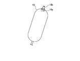
- FIG. 2 is a diagram showing an opening 10a of the tube 10 in a state where the cap 30 is removed.
- the opening 10a is provided with a drinking spout 10b.
- the spout 10b has a known check valve structure.
- the spout 10b has, for example, a screw formed on the outer surface and is removably screwed to the tube 10.
- the spout 10b may be fitted to the tube to open and close the tube.
- the spout 10b may be engaged with the tube due to its uneven shape to open and close the tube.
- the tube 10 is provided with coolant accommodating portions 10c and throttle portions 10d alternately along the longitudinal direction. Both ends of the tube 10 in the longitudinal direction are coolant accommodating portions 10c.
- the coolant accommodating portion 10c accommodates and holds the coolant 20.
- the inner diameter of the throttle portion 10d is smaller than the inner diameter of the coolant accommodating portion 10c.
- the throttle portion 10d circulates the coolant 20 in a fluid state between the coolant accommodating portions 10c adjacent to each other in the longitudinal direction.
- the hook 10e is provided at the end opposite to the end where the opening 10a in the longitudinal direction of the tube 10 is provided.
- the hook 10e can be engaged with the drawer handle 40.
- the hook 10e of the first cooling device CE1 and the drawer handle 40 of the second cooling device CE2 are engaged with each other.
- the coolant 20 is filled in the tube 10.
- the coolant 20 is a drinkable substance that exhibits fluidity at the temperature of the environment in which the user H is active.
- the coolant 20 for example, water, salt water, a sweetened solution, a liquid or jelly containing nutrients, an oral rehydration solution, an electrolyte solution, or the like can be used.
- the coolant 20 has a temperature lower than the temperature of the body surface of the user H, for example, is frozen and is in an individual state.
- the cap 30 opens and closes the opening 10a of the tube 10.
- the cap 30 has, for example, a cup-like shape, has a screw formed on the inner side surface, and is removably screwed to the tube 10.
- the cap 30 may be fitted to the tube to open and close the tube.
- the cap 30 may open and close the tube by engaging with the tube due to the uneven shape.
- the drawer handle 40 has a string shape, and both ends are attached to the cap 30.
- the drawer handle may be attached to the coolant accommodating portion 10c to which the cap 30 is attached instead of the cap 30.
- the storage container 50 stores the cooling device CE.
- the storage container 50 includes a container portion 50a and a lid portion 50b.
- the container portion 50a has a box-like shape that opens on one side.
- the container portion 50a includes an exterior portion 50c and a heat insulating portion 50d.
- the exterior portion 50c forms the outer surface of the container portion 50a.
- cloth or polyester can be used for the exterior portion 50c.
- the heat insulating portion 50d forms the inner surface of the container portion 50a.
- a heat insulating material such as aluminum foil, polyurethane foam, or batting can be used.
- the lid portion 50b covers the opening of the container portion 50a.
- the lid portion 50b for example, cloth, polyester, or the like can be used.
- the edge of the lid portion 50b is joined to the end of the opening of the container portion 50a.
- the lid portion 50b has a slit 50e.
- the user H takes out the cooling device CE from the storage container 50.
- the user H inserts his / her hand into the container portion 50a through the slit 50e.
- the user H for example, grabs the drawer handle 40 and takes out the first cooling device CE1 from the storage container 50 through the slit 50e.
- FIG. 3 shows a state in which the first cooling device CE1 is taken out from the storage container 50. As shown in FIG. 3, the first cooling device CE1 is taken out from the storage container 50 and the tube 10 is stretched when in use.
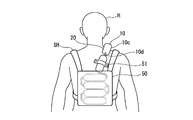
- FIG. 4 is a diagram showing the back of the user H in a state where the user H puts the tube 10 on the body surface and drinks the coolant 20.
- the user H carries the storage container 50 via, for example, the shoulder harness SH.
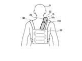
- FIG. 5 is a view showing the front of the user H in a state where the user H puts the tube 10 on the body surface and drinks the coolant 20. As shown in FIG. 5, the user H removes the cap 30 from the tube 10 and holds the drinking spout 10b. The user H absorbs the heat of his / her own body and drinks the coolant 20 in a state of showing fluidity in a timely manner.
- the user H further pulls out the first cooling device CE1 from the storage container 50 when the coolant 20 of the portion corresponding to the body surface of the user H of the first cooling device CE1 is lost due to drinking or the like. Further, when the coolant 20 of the portion corresponding to the body surface of the user H of the first cooling device CE1 becomes the same temperature as the body temperature of the user H due to the absorption of heat, the user H starts from the storage container 50. Pull out the first coolant CE1 further.
- the user H further pulls out the first cooling device CE1 from the storage container 50 when the coolant 20 of the portion corresponding to the body surface of the user H of the first cooling device CE1 is lost or the temperature rises.
- the user H puts the portion of the first cooling device CE1 on which the coolant 20 having a temperature lower than his / her body temperature is held on the body surface.
- User H further pulls out the first cooling device CE1 from the storage container 50 when the coolant 20 of the first cooling device CE1 is completely consumed.
- the user H takes out the second cooling device CE2 connected to the first cooling device CE1 by further pulling out the first cooling device CE1 from the storage container 50.
- the user H continues to cool his / her body surface and drink the coolant 20 by using the second cooling device CE2.
- the user H can carry the tube 10 filled with the coolant 20, and the tube 10 can be applied to cool the body surface of the user H.
- the user H can replenish water and salt by drinking the coolant 20 from the drinking spout 10b provided in the tube 10.
- the inner diameter of the throttle portion 10d is smaller than the inner diameter of the coolant accommodating portion 10c. Therefore, even if the frozen coolant 20 is present in the throttle portion 10d, the user H can break the frozen coolant 20 to fold the tube 10 in the throttle portion 10d or stretch the tube 10. Even if the coolant 20 is a substance that freezes at a temperature equal to or lower than the normal temperature of the user H, the user H can fold the tube 10 or stretch the tube 10. Therefore, the tube 10 can follow the body surface of the user H. Even if the coolant 20 is lost from the coolant accommodating portion 10c of the tube 10 which is the body surface of the user H due to the coolant 20 being melted and drunk, another coolant accommodating portion is newly provided from the storage container 50. By pulling out 10c, the user H can continue to cool the body surface.
- the inner surface of the storage container 50 for storing the tube 10 is the heat insulating portion 50d, it is suppressed that the tube 10 absorbs heat from other than the body surface of the user H.
- the tube 10 has a hook 10e to which the drawer handle 40 can be engaged, a plurality of tubes 10 can be connected.
- the drinking port 10b of the tube 10 has a check valve structure, even if the user H once releases the drinking port 10b, air does not enter the tube 10. Therefore, when the user H tries to drink the coolant 20 by adding the drinking spout 10b again, the user H is prevented from inhaling air.
- the tube 10 is taken out from the storage container 50 through the slit 50e. Therefore, when the tube 10 is taken out from the storage container 50, the formation of an opening in the storage container 50 is suppressed, and the temperature rise inside the storage container 50 is suppressed.
- FIG. 6 is a diagram showing a modified example of the cooling device 100.
- the cooling device 100 may include a strap (guide member) 51 as a guide member for guiding the arrangement of the tube 10 on the body surface of the user H.
- the strap 51 is formed in a band shape, and both ends are attached to the clothes of the user H (not shown) and attached to the user H.
- the strap 51 passes the tube 10 between the strap and the clothes and guides the arrangement of the tube 10 on the body surface of the user H.
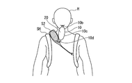
- the cooling device 100 may include a mesh-like and tubular band (guide member) 52.
- the band 52 is provided along the body surface of the user H from the storage container 50 to the shoulder harness SH, and is attached to the user H, for example.
- the band 52 passes the tube 10 inside and guides the arrangement of the tube 10 on the body surface of the user H.
- FIG. 9 is a diagram showing a modified example of the cooling device 100.
- the cooling device 100 may include a covering member 53 that covers the tube 10.
- the covering member 53 is formed of, for example, a cloth or the like.
- the covering member 53 covers the outer peripheral surface of the tube 10 filled with the coolant 20, and prevents the tube 10 from directly contacting the body surface of the user H and causing the user H to feel uncomfortable.
- the covering member 53 may be provided with a heat insulating material on the inner peripheral surface on the side that does not come into contact with the body surface of the user H.
- the storage container does not have a slit 50e, and the opening of the container portion 50a may be covered with a tab.
- the cooling device 200 includes full-body clothing 61, such as protective clothing and a costume, which is worn so as to cover the entire body of the user H.
- the cooling device 200 cools the body surface of the user H with the coolant 20.
- the cooling device 200 includes a cooling device CE, a full-body clothing 61, and a storage container 62.
- the cooling device CE has the same configuration as the cooling device CE of the cooling device 100.
- the whole body clothing 61 is worn so as to cover the whole body of the user H, and has a protective function such as chemical protection or a design in the form of a character.
- the whole body clothes 61 has a cooling device insertion portion 61a, a pull-out slit 61b, and an insertion slit 61c.
- the cooling device insertion portion 61a is provided inside the whole body clothing 61.
- the cooling device insertion portion 61a is formed in a tubular shape using a cloth, a sheet material, or the like.
- the cooling device insertion portion 61a can retract the tube 10 of the cooling device CE.
- a material having high airtightness or thermal conductivity may be used for the cooling device insertion portion 61a.
- one opening 61d and the other opening 61e are joined to the inner surface of the whole body clothing 61.
- the pull-out slit 61b is formed in the whole body clothes 61 in a range surrounded by the joint portion between the whole body clothes 61 and the opening 61d.
- the insertion slit 61c is formed in the whole body clothes 61 in a range surrounded by the joint portion between the whole body clothes 61 and the opening 61e.
- the storage container 62 stores the cooling device CE.
- the storage container 62 includes a container portion 62a and a lid portion 62b.
- the container portion 62a has a box-like shape that opens on one side.
- the container portion 62a is connected to the whole body clothes 61 so as to face the insertion slit 61c of the whole body clothes 61.
- the container portion 62a includes an exterior portion 62c, a heat insulating portion 62d, and a slit 62e.
- the exterior portion 62c forms the outer surface of the container portion 62a.
- the heat insulating portion 62d forms the inner surface of the container portion 62a.
- the heat insulating portion 62d for example, aluminum foil or the like can be used.
- the slit 62e is formed in the container portion 62a so as to face the insertion slit 61c of the whole body clothing 61.
- the lid portion 62b opens and closes the opening of the container portion 62a.
- the lid portion 62b for example, cloth or polyester can be used.
- the edge of the lid portion 62b is connected to the opening of the container portion 62a by using, for example, a fastener.
- the user H When using the cooling device 200, first, the user H opens the lid portion 62b of the storage container 62 and stores the cooling device CE in the storage container 62.
- User H inserts the tube 10 of the cooling device CE from the storage container 62 into the cooling device insertion portion 61a via the slit 62e and the insertion slit 61c. User H inserts the tube 10 over the entire length of the cooling device insertion portion 61a.
- User H closes the lid 62b of the storage container 62. User H wears full-body clothing 61.
- the user H who is active wearing the whole body clothes 61 carries the tube 10 filled with the coolant 20 and puts the tube 10 through the cooling device insertion portion 61a to the user H. Can cool the body surface of.
- the cooling device 200 can pull out the cooling device CE from the pull-out slit 61b.
- the lid portion 62b of the storage container 62 connected to the outside of the whole body clothes 61 can be opened and closed.
- the cooling device CE can be inserted from the storage container 62 into the cooling device insertion portion 61a via the slit 62e and the insertion slit 61c. Therefore, the cooling device CE that has reached the temperature of the environment in which the user H is active is pulled out from the drawing slit 61b and discarded.
- the collaborator or the like can store the cooling device CE in the storage container 62 again and insert the tube 10 into the cooling device insertion portion 61a.
- the user H who is active wearing the whole body clothes 61 can continuously cool the body surface.
- the user H can take in the cooling device CE, which has reached the temperature of the environment in which the user H is active, into the whole body clothes 61, and drink the coolant 20 to rehydrate.
- the cooling device 300 includes full-body clothing 71, such as protective clothing and a costume, which is worn so as to cover the entire body of the user H.
- the cooling device 300 is a cooling device capable of replenishing water by drinking the coolant 20 while cooling the body surface of the user H with the coolant 20.
- the cooling device 300 includes a full-body clothing 71, a storage container 50, a band 52, and a tube 10.
- the whole body clothes 71 do not have the cooling device insertion portion 61a, the pull-out slit 61b, and the insertion slit 61c.
- the full-body clothing 71 has the tube 10 pulled inside, including the storage container 50.
- the storage container 50 is arranged inside the whole body clothes 71.
- the band 52 is arranged, for example, along the inner surface of the full-body clothing 71.
- the tube 10 is stored in the storage container 50, passes through the band 52, and the drinking spout 10b is added to the user H.
- the user H who is active wearing the whole body clothes 71 carries the tube 10 filled with the coolant 20 and puts the tube 10 through the band 52 on the body surface of the user H. Can be cooled. User H can replenish hydration by drinking the coolant 20 from the drinking spout 10b provided in the tube 10.
- the squeezed portion of the tube does not have an outer diameter and an inner diameter smaller than those of the coolant accommodating portion 10c, but for example, the inner surfaces of the tubes are heat-welded to form a seal portion S to squeeze the inner diameter. You may.
- the tube does not have a drawing portion 10d and may be filled with a plurality of frozen and block-shaped coolants 20.
- the tube is filled with the coolant 20 in a fluid state (filling step).
- the tube is sandwiched by a plate sandwiching BS or the like over the entire length of the tube in the lateral direction.
- a pressure orthogonal to the longitudinal direction of the tube is applied to the tube to divide the range ER in which the coolant 20 exists in the tube (division step).
- the tube filled with the coolant 20 and the range ER in which the coolant 20 exists is divided is cooled to a temperature equal to or lower than the normal temperature of a person (cooling step).
- the tube does not have a throttle portion 10d and may be filled with an antifreeze coolant 20A.
- the end on the opposite side of the longitudinal direction from the end where the opening 10a of the tube is formed may be opened and closed so that the coolant can be filled, the air inside the tube can be evacuated, or the inside of the tube can be cleaned quickly. ..
Landscapes
- Health & Medical Sciences (AREA)
- Vascular Medicine (AREA)
- Thermal Sciences (AREA)
- Engineering & Computer Science (AREA)
- Biomedical Technology (AREA)
- Heart & Thoracic Surgery (AREA)
- Physics & Mathematics (AREA)
- Life Sciences & Earth Sciences (AREA)
- Animal Behavior & Ethology (AREA)
- General Health & Medical Sciences (AREA)
- Public Health (AREA)
- Veterinary Medicine (AREA)
- Thermotherapy And Cooling Therapy Devices (AREA)
Abstract
本冷却装具は、長手方向の一方の端部に開口部(10a)を有するチューブ(10)と、開口部(10a)を開閉可能であるキャップ(30)と、チューブ(10)に充填され、飲用可能であり、不凍性である冷却材(20)と、冷却材(20)が充填されたチューブ(10)を収納する収納容器(50)と、を備え、前記チューブは、内径が絞られる絞り部(10d)を有する。
Description
本発明は、冷却装具及び冷却装具の製造方法に関する。
従来、人や動物が装着し、人や動物の体表を冷却する冷却装具が提案されている。
例えば、家畜やペットを寒冷ストレスや温度ストレスから保護する動物用被服が提案されている。非特許文献1には、犬の首に巻かれ、保冷剤を収納し、犬の体表を冷却可能なバンダナについて記載されている。
[online]、2020年、 [2020年1月8日検索]、インターネット<URL:https://www.amazon.co.jp/dp/B076CZ1RZL/ref=psdc_2155279051_t2_B07DN6NMHV>
ところで、近年、地球温暖化や熱波に伴い、熱中症を発症する人が増加している。特に、屋外で活動中の人が熱中症を発症する場合が多い。屋外で活動中の人の熱中症の発生を予防するためには、人に携行され人体の体表を継続的に冷却可能な冷却装具が必要である。また、熱中症の発生を予防するためには、体表の冷却と同時に水分補給が必要である。
非特許文献1に記載されているバンダナは、人へ適用できたとしても、冷却材が首に一巻きされる程度の容量しかなく、人の体表を継続的に冷却することはできない。また、非特許文献1に記載されているバンダナは、使用者の水分補給の手段を備えていないという問題があった。
上記事情を踏まえ、本発明は、携行可能であり、人体の体表の継続的な冷却及び水分補給が可能な冷却装具及び冷却装具の製造方法の提供を目的とする。
本発明の一態様に係る冷却装具は、長手方向の一方の端部のみに開口部を有するチューブと、前記開口部を開閉可能であるキャップと、前記チューブに充填され、飲用可能であり、不凍性である冷却材と、前記冷却材が充填された前記チューブを収納する収納容器と、を備え、前記チューブは、内径が絞られる絞り部を有する。
本発明の一態様に係る冷却装具の製造方法は、前記チューブに流動性を有する状態の前記冷却材を充填する充填工程と、前記チューブの前記長手方向に直交した圧力を前記チューブに加え、前記チューブ内において前記冷却材の存在する範囲を分断する分断工程と、を有する。
上記冷却装具及び冷却装具の製造方法によれば、携行可能であり、人体の体表の継続的な冷却及び水分補給が可能な冷却装具及び冷却装具の製造方法を提供することができる。
本発明の第一実施形態について、図1から図9を参照して説明する。
本実施形態に係る冷却装具100は、携行可能であり、冷却材20で使用者の体表を冷却しつつ、使用者が冷却材20を飲用して水分補給可能な冷却装具である。
本実施形態に係る冷却装具100は、携行可能であり、冷却材20で使用者の体表を冷却しつつ、使用者が冷却材20を飲用して水分補給可能な冷却装具である。
図1は、本発明の第一実施形態に係る冷却装具100の斜視図である。図1に示すように、冷却装具100は、冷却器具CEと、収納容器50と、を備える。冷却器具CEは、チューブ10と、冷却材20と、キャップ30と、引出ハンドル40と、を備える。本実施形態では、冷却器具CEは、同様の構成である第一冷却器具CE1と、第二冷却器具CE2と、が連結されている。
チューブ10は、例えばポリエチレン、ポリプロピレン、ポリビニルアルコール、ニトリルゴム又はシリコーン等の樹脂材料により形成される。樹脂材料は上記に限定されず防水膜となる高分子材料、エラストマーを広く用いることができる。チューブ10は、長尺である。図1は、チューブ10が長手方向に折り畳まれている状態を示す。
チューブ10は、開口部10aと、冷却材収容部10cと、絞り部10dと、フック10eと、を有する。
チューブ10の開口部10aは、チューブ10の長手方向の一方の端部に設けられる。チューブ10は、開口部10aが、キャップ30により開閉可能である。図2は、キャップ30を取り外した状態におけるチューブ10の開口部10aを示す図である。図2に示すように、開口部10aには、飲み口10bが設けられている。飲み口10bは公知の逆止弁構造を有する。飲み口10bは、例えば外側面にねじが形成され、チューブ10に取り外し可能に螺着される。飲み口10bは、チューブに嵌合されてチューブを開閉してもよい。飲み口10bは、凹凸形状によりチューブに係合してチューブを開閉してもよい。
図1に示すように、チューブ10には、長手方向に沿って、冷却材収容部10cと絞り部10dとが交互に設けられている。チューブ10は、長手方向の両端が冷却材収容部10cとなっている。
冷却材収容部10cは、冷却材20を収容して保持する。絞り部10dの内径は、冷却材収容部10cの内径より小さい。絞り部10dは、長手方向に隣接する冷却材収容部10cの間で、流動性を有する状態にある冷却材20を流通させる。
フック10eは、チューブ10の長手方向の開口部10aが設けられた端部とは他方の端部に設けられる。フック10eは、引出ハンドル40と係合可能である。図1においては、第一冷却器具CE1のフック10eと、第二冷却器具CE2の引出ハンドル40と、が係合している。
冷却材20は、チューブ10に充填される。冷却材20は、使用者Hが活動する環境の温度では流動性を示し、飲用可能な物質である。冷却材20としては、例えば水、塩水、加糖液、若しくは栄養分等を含む液体若しくはジェリー、経口補水液又は電解質溶液等が使用できる。冷却材20は、使用者Hが冷却装具100を装着する際は、使用者Hの体表の温度より低い温度とされ、例えば冷凍され個体の状態とされる。
キャップ30は、チューブ10の開口部10aを開閉する。キャップ30は、例えばカップ状の形状を有し、内側面にねじが形成され、チューブ10に取り外し可能に螺着される。キャップ30は、チューブに嵌合されてチューブを開閉してもよい。キャップ30は、凹凸形状によりチューブに係合してチューブを開閉してもよい。
引出ハンドル40は、紐状であり、両端がキャップ30に取り付けられる。引出ハンドルは、キャップ30ではなく、キャップ30が取り付けられる冷却材収容部10cに取り付けられてもよい。
収納容器50は、冷却器具CEを収納する。収納容器50は、容器部50aと、蓋部50bと、を備える。
容器部50aは、一方に開口する箱状の形状を有する。容器部50aは、外装部50cと、断熱部50dと、を備える。外装部50cは、容器部50aの外表を形成する。外装部50cは、例えば布又はポリエステル等が使用できる。断熱部50dは、容器部50aの中表を形成する。断熱部50dは、例えばアルミホイル、ポリウレタンフォーム、中綿等の断熱性材料等が使用できる。
蓋部50bは、容器部50aの開口を覆う。蓋部50bは、例えば布やポリエステル等が使用できる。蓋部50bは、縁が容器部50aの開口の端部に接合される。蓋部50bは、スリット50eを有する。
次に、冷却装具100の使用時の動作について説明する。使用者Hは、まず、収納容器50から冷却器具CEを取り出す。使用者Hは、スリット50eを通して、容器部50aの内部に手を挿入する。使用者Hは、例えば引出ハンドル40を掴み、スリット50eを通して第一冷却器具CE1を収納容器50から取り出す。
図3は、収納容器50から第一冷却器具CE1を取り出した状態を示す。図3に示すように、第一冷却器具CE1は、使用時は、収納容器50から取り出され、チューブ10が引き伸ばされる。
図4は、使用者Hがチューブ10を体表にあてて冷却材20を飲用している状態における使用者Hの背部を示す図である。図4に示すように、使用者Hは、例えばショルダーハーネスSHを介して収納容器50を携行する。
図5は、使用者Hがチューブ10を体表にあてて冷却材20を飲用している状態における使用者Hの正面を示す図である。図5に示すように、使用者Hは、チューブ10からキャップ30を外し、飲み口10bをくわえる。使用者Hは、自己の体等の熱を吸収し、流動性を示す状態となった冷却材20を適時飲用する。
使用者Hは、飲用等により、第一冷却器具CE1の使用者Hの体表にあたる部分の冷却材20が喪失した場合に、収納容器50から第一冷却器具CE1をさらに引き出す。また、使用者Hは、熱の吸収により、第一冷却器具CE1の使用者Hの体表にあたる部分の冷却材20が使用者Hの体温と同等の温度になった場合に、収納容器50から第一冷却器具CE1をさらに引き出す。
このようにして、使用者Hは、第一冷却器具CE1の使用者Hの体表にあたる部分の冷却材20が喪失又は温度上昇した場合に、第一冷却器具CE1を収納容器50からさらに引き出す。使用者Hは、自己の体温より低い温度の冷却材20が保持された第一冷却器具CE1の部分を体表にあてる。
使用者Hは、第一冷却器具CE1の冷却材20を消費しきった場合等に、第一冷却器具CE1を収納容器50からさらに引き出す。使用者Hは、第一冷却器具CE1を収納容器50からさらに引き出すことにより、第一冷却器具CE1に連結された第二冷却器具CE2を取り出す。使用者Hは、第二冷却器具CE2を使用して、自己の体表の冷却と、冷却材20の飲用と、を継続する。
冷却装具100によれば、使用者Hが、冷却材20が充填されたチューブ10を携行可能であり、チューブ10をあてて使用者Hの体表を冷却できる。使用者Hは、チューブ10に設けられた飲み口10bから、冷却材20を飲用して水分や塩分の補給ができる。
チューブ10は、絞り部10dの内径が冷却材収容部10cの内径より小さい。そのため、絞り部10dに凍った冷却材20が存在しても、使用者Hは、凍った冷却材20を破壊して絞り部10dにおいてチューブ10を折り畳められ、又はチューブ10を引き伸ばせる。冷却材20が使用者Hの平熱以下の温度で凍る物質であっても、使用者Hは、チューブ10を折り畳められ、又はチューブ10を引き伸ばせる。そのため、チューブ10は、使用者Hの体表に沿うことができる。冷却材20が溶融して飲用されることにより、使用者Hの体表にあたるチューブ10の冷却材収容部10cから冷却材20が喪失しても、収納容器50から新たに別の冷却材収容部10cを引き出すことにより、使用者Hが体表の冷却を継続できる。
チューブ10を収納する収納容器50の中表が断熱部50dであるため、チューブ10が使用者Hの体表以外から熱を吸収することが抑制される。
チューブ10が、引出ハンドル40を係合可能なフック10eを有するため、複数のチューブ10をつなげられる。
チューブ10の飲み口10bが逆止弁構造であるため、使用者Hが一旦飲み口10bを離しても、チューブ10内に空気が混入することがない。そのため、使用者Hが再度飲み口10bをくわえて冷却材20の飲用しようとした場合に使用者Hが空気を吸入することが防止される。
チューブ10が、収納容器50からスリット50eを介して取り出される。そのため、収納容器50からチューブ10が取り出される場合に収納容器50に開口が形成されることが抑制され、収納容器50内部の温度上昇が抑制される。
図6は、冷却装具100の変形例を示す図である。図6に示すように、冷却装具100は、使用者Hの体表におけるチューブ10の配置をガイドするガイド部材として、ストラップ(ガイド部材)51を備えてもよい。ストラップ51は、バンド状に形成され、両端が使用者Hの衣服(不図示)に取り付けられ、使用者Hに装着される。ストラップ51は、衣服との間にチューブ10を通し、チューブ10の使用者Hの体表における配置をガイドする。
図7及び図8は、冷却装具100の変形例を示す図である。図7及び図8に示すように、冷却装具100は、メッシュ状で筒状のバンド(ガイド部材)52を備えてもよい。バンド52は、例えば収納容器50からショルダーハーネスSHにかけて使用者Hの体表に沿って設けられ、使用者Hに装着される。バンド52は、内部にチューブ10を通し、チューブ10の使用者Hの体表における配置をガイドする。
図9は、冷却装具100の変形例を示す図である。図9に示すように、冷却装具100は、チューブ10を覆う被覆部材53を備えてもよい。被覆部材53は、例えば布等で形成される。被覆部材53は、冷却材20が充填されたチューブ10の外周面を覆い、チューブ10が直接使用者Hの体表に接触し、使用者Hが不快を感じることを抑制する。被覆部材53は、使用者Hの体表に接触しない側の内周面に断熱材を備えていてもよい。
収納容器は、スリット50eを有さず、タブにより容器部50aの開口を覆ってもよい。
次に、本発明の第二実施形態について、図10を参照して説明する。
本実施形態に係る冷却装具200は、例えば防護服や着ぐるみ等の、使用者Hの全身を覆うように着用される全身服61を備える。冷却装具200は、冷却材20で使用者Hの体表を冷却する。
本実施形態に係る冷却装具200は、例えば防護服や着ぐるみ等の、使用者Hの全身を覆うように着用される全身服61を備える。冷却装具200は、冷却材20で使用者Hの体表を冷却する。
図10に示すように、冷却装具200は、冷却器具CEと、全身服61と、収納容器62と、を備える。冷却器具CEは、冷却装具100の冷却器具CEと同様の構成である。
全身服61は、使用者Hの全身を覆うよう着用され、化学防護等の防護機能又はキャラクターの形態のデザインを有する。
全身服61は、冷却器具挿入部61aと、引抜きスリット61bと、挿入スリット61cを有する。
冷却器具挿入部61aは、全身服61の内部に設けられる。冷却器具挿入部61aは、布やシート材等を使用して筒状に形成される。冷却器具挿入部61aは、冷却器具CEのチューブ10を引込可能である。冷却器具挿入部61aは、気密性又は熱伝導性が高い材料が用いられてもよい。冷却器具挿入部61aは、一方の開口部61d及び他方の開口部61eが全身服61の内面に接合される。
引抜きスリット61bは、全身服61に、全身服61と開口部61dとの接合部分で囲まれた範囲に形成される。挿入スリット61cは、全身服61に、全身服61と開口部61eとの接合部分で囲まれた範囲に形成される。
収納容器62は、冷却器具CEを収納する。収納容器62は、容器部62aと、蓋部62bと、を備える。
容器部62aは、一方に開口する箱状の形状を有する。容器部62aは、全身服61の挿入スリット61cと対向するように、全身服61に接続される。容器部62aは、外装部62cと、断熱部62dと、スリット62eを備える。
外装部62cは、容器部62aの外表を形成する。外装部62cは、例えば布やポリエステル等が使用できる。断熱部62dは、容器部62aの中表を形成する。断熱部62dは、例えばアルミホイル等が使用できる。スリット62eは、全身服61の挿入スリット61cと対向するように、容器部62aに形成される。
蓋部62bは、容器部62aの開口を開閉する。蓋部62bは、例えば布やポリエステル等が使用できる。蓋部62bは、例えばファスナーを使用して、縁が容器部62aの開口に接続される。
冷却装具200の使用時は、まず、使用者Hが、収納容器62の蓋部62bを開け、収納容器62に冷却器具CEを収納する。
使用者Hは、冷却器具CEのチューブ10を、スリット62e及び挿入スリット61cを介して、収納容器62から冷却器具挿入部61aに挿入する。使用者Hは、チューブ10を、冷却器具挿入部61aの全長にわたって挿入する。
使用者Hは、収納容器62の蓋部62bを閉じる。使用者Hは、全身服61を着用する。
冷却装具200によれば、全身服61を着用して活動する使用者Hが、冷却材20が充填されたチューブ10を携行し、冷却器具挿入部61aを介してチューブ10をあてて使用者Hの体表を冷却できる。
冷却装具200は、引抜きスリット61bから冷却器具CEを引抜き可能である。全身服61の外側に接続された収納容器62の蓋部62bが開閉可能である。冷却器具CEは、スリット62e及び挿入スリット61cを介して収納容器62から冷却器具挿入部61aに挿入可能である。そのため、使用者Hが活動する環境の温度となった冷却器具CEは、引抜きスリット61bから引き抜いて廃棄される。使用者Hが活動する環境の温度となった冷却器具CEが廃棄された後、共同作業者等が、再び収納容器62に冷却器具CEを収納し、冷却器具挿入部61aにチューブ10を挿入可能である。そのため、全身服61を着用して活動する使用者Hが体表を継続して冷却できる。使用者Hは、使用者Hが活動する環境の温度となった冷却器具CEを全身服61の内部に取り入れ、冷却材20を飲用して水分補給できる。
次に、本発明の第三実施形態について、図11を参照して説明する。
本実施形態に係る冷却装具300は、例えば防護服や着ぐるみ等の、使用者Hの全身を覆うように着用される全身服71を備える。冷却装具300は、冷却材20で使用者Hの体表を冷却しつつ、冷却材20を飲用して水分補給を可能とする冷却装具である。
本実施形態に係る冷却装具300は、例えば防護服や着ぐるみ等の、使用者Hの全身を覆うように着用される全身服71を備える。冷却装具300は、冷却材20で使用者Hの体表を冷却しつつ、冷却材20を飲用して水分補給を可能とする冷却装具である。
冷却装具300は、全身服71と、収納容器50と、バンド52と、チューブ10と、を備える。
全身服71は、冷却装具200の全身服61と異なり、冷却器具挿入部61a、引抜きスリット61b、及び挿入スリット61cを有さない。全身服71は、収納容器50を含めてチューブ10を内部に引き込んでいる。
収納容器50は、全身服71の内部に配置される。バンド52は、例えば全身服71の内面に沿って配置される。チューブ10は、収納容器50に収納され、バンド52を通り、飲み口10bが使用者Hにくわえられる。
冷却装具300によれば、全身服71を着用して活動する使用者Hが、冷却材20が充填されたチューブ10を携行し、バンド52を介してチューブ10をあてて使用者Hの体表を冷却できる。使用者Hは、チューブ10に設けられた飲み口10bから、冷却材20を飲用して水分補給ができる。
以上、本発明の各実施形態について図面を参照して詳述したが、具体的な構成はこの実施形態に限られるものではなく、本発明の要旨を逸脱しない範囲の設計変更等も含まれる。また、上述の実施形態および以下で示す変形例において示した構成要素は適宜に組み合わせて構成することが可能である。
図12に示すように、チューブの絞り部は、冷却材収容部10cより外径及び内径を縮小するのではなく、例えばチューブの内面同士を熱溶着してシール部Sを形成し、内径を絞ってもよい。
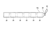
図13に示すように、チューブは、絞り部10dを有さず、冷凍されブロック状に成型された冷却材20を複数充填されてもよい。
冷凍されブロック状に成型された冷却材20をチューブに複数充填するには、まず、チューブに、流動性を有する状態の冷却材20を充填する(充填工程)。次に、図14に示すように、チューブの短手方向の全長にわたって板挟みBS等でチューブを挟む。これにより、チューブの長手方向に直交した圧力をチューブに加え、チューブ内において冷却材20の存在する範囲ERを分断する(分断工程)。次に、冷却材20が充填され、冷却材20の存在する範囲ERが分断されたチューブを、人の平熱以下の温度に冷却する(冷却工程)。
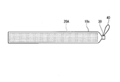
図15に示すように、チューブは、絞り部10dを有さず、不凍性の冷却材20Aが充填されてもよい。
チューブの開口部10aが形成される端部と長手方向の反対側の端部を開閉可能にして、冷却材の充填、チューブ内の空気抜き、又はチューブ内の洗浄を迅速に行えるようにしてもよい 。
100、200、300 冷却装具
10 チューブ
10a 開口部
10b 飲み口
10c 冷却材収容部
10d 絞り部
10e フック
20、20A 冷却材
30 キャップ
40 引出ハンドル
50、62 収納容器
50a、62a 容器部
50b、62b 蓋部
50c、62c 外装部
50d、62d 断熱部
50e、62e スリット
51 ストラップ(ガイド部材)
52 バンド(ガイド部材)
53 被覆部材
61、71 全身服
61a 冷却器具挿入部
CE 冷却器具
H 使用者
SH ショルダーハーネス
10 チューブ
10a 開口部
10b 飲み口
10c 冷却材収容部
10d 絞り部
10e フック
20、20A 冷却材
30 キャップ
40 引出ハンドル
50、62 収納容器
50a、62a 容器部
50b、62b 蓋部
50c、62c 外装部
50d、62d 断熱部
50e、62e スリット
51 ストラップ(ガイド部材)
52 バンド(ガイド部材)
53 被覆部材
61、71 全身服
61a 冷却器具挿入部
CE 冷却器具
H 使用者
SH ショルダーハーネス
Claims (7)
- 長手方向の一方の端部に開口部を有するチューブと、
前記開口部を開閉可能であるキャップと、
前記チューブに充填され、飲用可能であり、不凍性である冷却材と、
前記冷却材が充填された前記チューブを収納する収納容器と、を備え、
前記チューブは、内径が絞られる絞り部を有する、
冷却装具。 - 前記収納容器は、内面に断熱部を有する、
請求項1に記載の冷却装具。 - 前記チューブの外周面を覆う被覆部材を有する、
請求項1又は請求項2に記載の冷却装具。 - 人が装着可能であり、前記チューブを前記収納容器からガイドするガイド部材を有する、
請求項1から請求項3のうちいずれか一項に記載の冷却装具。 - 前記収納容器が取り付けられ、前記チューブを内部に引込可能な全身服を備える、
請求項1から請求項4のうちいずれか一項に記載の冷却装具。 - 前記チューブは、前記開口部に逆止機能を有する飲み口を備える、
請求項1から請求項5のうちいずれか一項に記載の冷却装具。 - 請求項1に記載の冷却装具の製造方法であって、
前記チューブに流動性を有する状態の前記冷却材を充填する充填工程と、
前記チューブの前記長手方向に直交した圧力を前記チューブに加え、前記チューブ内において前記冷却材の存在する範囲を分断する分断工程と、
を有する、
冷却装具の製造方法。
Priority Applications (3)
| Application Number | Priority Date | Filing Date | Title |
|---|---|---|---|
| PCT/JP2020/004872 WO2021157066A1 (ja) | 2020-02-07 | 2020-02-07 | 冷却装具及び冷却装具の製造方法 |
| US17/796,867 US20230059586A1 (en) | 2020-02-07 | 2020-02-07 | Cooling equipment and method for producing cooling equipment |
| JP2021575562A JP7299536B2 (ja) | 2020-02-07 | 2020-02-07 | 冷却装具及び冷却装具の製造方法 |
Applications Claiming Priority (1)
| Application Number | Priority Date | Filing Date | Title |
|---|---|---|---|
| PCT/JP2020/004872 WO2021157066A1 (ja) | 2020-02-07 | 2020-02-07 | 冷却装具及び冷却装具の製造方法 |
Publications (1)
| Publication Number | Publication Date |
|---|---|
| WO2021157066A1 true WO2021157066A1 (ja) | 2021-08-12 |
Family
ID=77200481
Family Applications (1)
| Application Number | Title | Priority Date | Filing Date |
|---|---|---|---|
| PCT/JP2020/004872 Ceased WO2021157066A1 (ja) | 2020-02-07 | 2020-02-07 | 冷却装具及び冷却装具の製造方法 |
Country Status (3)
| Country | Link |
|---|---|
| US (1) | US20230059586A1 (ja) |
| JP (1) | JP7299536B2 (ja) |
| WO (1) | WO2021157066A1 (ja) |
Citations (3)
| Publication number | Priority date | Publication date | Assignee | Title |
|---|---|---|---|---|
| JPH07310208A (ja) * | 1994-05-12 | 1995-11-28 | Daikin Ind Ltd | 温度調節衣服 |
| US20050145372A1 (en) * | 2004-01-02 | 2005-07-07 | Noel Thomas P. | Method and thermally active multi-phase heat transfer apparatus and method for abstracting heat using liquid bi-phase heat exchanging composition |
| US20060191063A1 (en) * | 2004-05-11 | 2006-08-31 | William Elkins | Garment for a cooling and hydration system |
Family Cites Families (3)
| Publication number | Priority date | Publication date | Assignee | Title |
|---|---|---|---|---|
| US7875011B2 (en) * | 2002-02-26 | 2011-01-25 | Harvie Mark R | Cooling, heating, bladder relief, gas, hydration and nutrition chem-bio suit connectivity system |
| US20040079517A1 (en) * | 2002-10-29 | 2004-04-29 | Med-Eng Systems Inc. | Body cooling apparatus |
| US7959657B1 (en) * | 2004-07-07 | 2011-06-14 | Harsy Douglas R | Portable thermal therapeutic apparatus and method |
-
2020
- 2020-02-07 US US17/796,867 patent/US20230059586A1/en not_active Abandoned
- 2020-02-07 WO PCT/JP2020/004872 patent/WO2021157066A1/ja not_active Ceased
- 2020-02-07 JP JP2021575562A patent/JP7299536B2/ja active Active
Patent Citations (3)
| Publication number | Priority date | Publication date | Assignee | Title |
|---|---|---|---|---|
| JPH07310208A (ja) * | 1994-05-12 | 1995-11-28 | Daikin Ind Ltd | 温度調節衣服 |
| US20050145372A1 (en) * | 2004-01-02 | 2005-07-07 | Noel Thomas P. | Method and thermally active multi-phase heat transfer apparatus and method for abstracting heat using liquid bi-phase heat exchanging composition |
| US20060191063A1 (en) * | 2004-05-11 | 2006-08-31 | William Elkins | Garment for a cooling and hydration system |
Also Published As
| Publication number | Publication date |
|---|---|
| US20230059586A1 (en) | 2023-02-23 |
| JPWO2021157066A1 (ja) | 2021-08-12 |
| JP7299536B2 (ja) | 2023-06-28 |
Similar Documents
| Publication | Publication Date | Title |
|---|---|---|
| US10544976B2 (en) | Soft-sided cooler | |
| US4399668A (en) | Individual beverage cooler | |
| US8177827B2 (en) | Cooling device for locally anesthetizing an area on the surface of the body | |
| WO2013140301A1 (en) | Cold therapy device | |
| US20190142629A1 (en) | Cooling pack and therapeutic tool used in cooling therapy | |
| KR20140141161A (ko) | 상변화물질을 이용한 아이스 목 밴드 | |
| EP2204150A1 (en) | Long-acting cold structure | |
| US20100125317A1 (en) | Long-Action Cold Pack Structure | |
| CN101489424A (zh) | 接触式冷却系统 | |
| US7335222B1 (en) | Cooling ear muffs | |
| KR20100093230A (ko) | 나노 쿨러 목 밴드 | |
| JP7299536B2 (ja) | 冷却装具及び冷却装具の製造方法 | |
| US20100319382A1 (en) | Blanket That Keeps A Person's Body Cool In The Hot Sun Complete With Matching Bag | |
| KR101187565B1 (ko) | 스탠딩 파우치 | |
| CN106490742A (zh) | 一种相变凉帽 | |
| CN110882104B (zh) | 一种亚低温眼底保护装置 | |
| KR20080096739A (ko) | 띠형태보냉온재꾸러미를 활용한 머플러겸용 띠 | |
| KR200455235Y1 (ko) | 환자용 보냉팩 | |
| WO2010013881A1 (ko) | 신체부위별 맞춤형 냉온 찜질팩 | |
| JP3210986B2 (ja) | 蓄熱保冷パックおよび蓄熱保冷パック具 | |
| JP6261969B2 (ja) | 氷嚢 | |
| CN218650740U (zh) | 一种保温背包 | |
| US20110139406A1 (en) | Pet Cooling Bed | |
| JP3147806U (ja) | 子供用巻き付け式保冷具 | |
| CN210285255U (zh) | 便携式药品冷藏箱 |
Legal Events
| Date | Code | Title | Description |
|---|---|---|---|
| 121 | Ep: the epo has been informed by wipo that ep was designated in this application |
Ref document number: 20917369 Country of ref document: EP Kind code of ref document: A1 |
|
| ENP | Entry into the national phase |
Ref document number: 2021575562 Country of ref document: JP Kind code of ref document: A |
|
| NENP | Non-entry into the national phase |
Ref country code: DE |
|
| 122 | Ep: pct application non-entry in european phase |
Ref document number: 20917369 Country of ref document: EP Kind code of ref document: A1 |