WO2021153378A1 - 緩衝器 - Google Patents
緩衝器 Download PDFInfo
- Publication number
- WO2021153378A1 WO2021153378A1 PCT/JP2021/001882 JP2021001882W WO2021153378A1 WO 2021153378 A1 WO2021153378 A1 WO 2021153378A1 JP 2021001882 W JP2021001882 W JP 2021001882W WO 2021153378 A1 WO2021153378 A1 WO 2021153378A1
- Authority
- WO
- WIPO (PCT)
- Prior art keywords
- peripheral surface
- spring receiver
- inner peripheral
- piston rod
- rod guide
- Prior art date
- Legal status (The legal status is an assumption and is not a legal conclusion. Google has not performed a legal analysis and makes no representation as to the accuracy of the status listed.)
- Ceased
Links
Images





Classifications
-
- B—PERFORMING OPERATIONS; TRANSPORTING
- B60—VEHICLES IN GENERAL
- B60G—VEHICLE SUSPENSION ARRANGEMENTS
- B60G11/00—Resilient suspensions characterised by arrangement, location or kind of springs
- B60G11/14—Resilient suspensions characterised by arrangement, location or kind of springs having helical, spiral or coil springs only
- B60G11/16—Resilient suspensions characterised by arrangement, location or kind of springs having helical, spiral or coil springs only characterised by means specially adapted for attaching the spring to axle or sprung part of the vehicle
-
- F—MECHANICAL ENGINEERING; LIGHTING; HEATING; WEAPONS; BLASTING
- F16—ENGINEERING ELEMENTS AND UNITS; GENERAL MEASURES FOR PRODUCING AND MAINTAINING EFFECTIVE FUNCTIONING OF MACHINES OR INSTALLATIONS; THERMAL INSULATION IN GENERAL
- F16F—SPRINGS; SHOCK-ABSORBERS; MEANS FOR DAMPING VIBRATION
- F16F1/00—Springs
- F16F1/02—Springs made of steel or other material having low internal friction; Wound, torsion, leaf, cup, ring or the like springs, the material of the spring not being relevant
- F16F1/04—Wound springs
- F16F1/12—Attachments or mountings
-
- F—MECHANICAL ENGINEERING; LIGHTING; HEATING; WEAPONS; BLASTING
- F16—ENGINEERING ELEMENTS AND UNITS; GENERAL MEASURES FOR PRODUCING AND MAINTAINING EFFECTIVE FUNCTIONING OF MACHINES OR INSTALLATIONS; THERMAL INSULATION IN GENERAL
- F16F—SPRINGS; SHOCK-ABSORBERS; MEANS FOR DAMPING VIBRATION
- F16F9/00—Springs, vibration-dampers, shock-absorbers, or similarly-constructed movement-dampers using a fluid or the equivalent as damping medium
- F16F9/32—Details
- F16F9/58—Stroke limiting stops, e.g. arranged on the piston rod outside the cylinder
Definitions
- the present invention relates to a shock absorber.
- the present application claims priority based on Japanese Patent Application No. 2020-011492 filed in Japan on January 28, 2020, the contents of which are incorporated herein by reference.
- an object of the present invention is to provide a shock absorber capable of suppressing the generation of abnormal noise.
- the shock absorber includes a cylinder in which a working fluid is sealed, a spring that is slidably fitted in the cylinder, and one end side connected to the piston and the other end side of the cylinder.
- a first spring including a piston rod extending to the outside and a rebound stopper mechanism for limiting the extension of the piston rod from the cylinder, and the rebound stopper mechanism is provided on the other end side of the piston rod.
- the first spring includes a receiver, a second spring receiver provided on one end side of the piston rod, and a coil spring provided between the first spring receiver and the second spring receiver.
- the spring receiver which is at least one of the receiver and the second spring receiver, is composed of a tubular portion that supports the coil spring and a flange portion formed at the end of the tubular portion, and is formed on the inner circumference of the spring receiver.
- the surface has a first surface at the position of the tubular portion and a second surface at the position of the flange portion, and a small diameter portion having a minimum diameter is formed on the first surface. ..
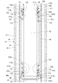
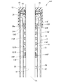
- FIG. 1 shows the shock absorber 11 of the first embodiment.
- the shock absorber 11 is used as a suspension device for vehicles such as automobiles and railroad vehicles. Specifically, the shock absorber 11 is used for a strut type suspension of an automobile. Although an example of application to a strut type suspension is shown in the present embodiment, it may be applied to a shock absorber, and it can also be applied to various suspension devices such as a twin tube and a monotube.
- the shock absorber 11 is a double-cylinder type shock absorber provided with a cylinder 17.
- the cylinder 17 has a cylindrical inner cylinder 15 and a bottomed tubular outer cylinder 16 having a diameter larger than that of the inner cylinder 15 and provided on the outer peripheral side of the inner cylinder 15. A working fluid is sealed in the cylinder 17.
- a reservoir chamber 18 is formed between the outer cylinder 16 and the inner cylinder 15.
- the outer cylinder 16 is an integrally molded product made of one metal member.
- the outer cylinder 16 has a cylindrical side wall portion 21, a bottom portion 22 that closes one end side of the side wall portion 21 in the axial direction, and an opening 23 on the side opposite to the bottom portion 22 of the side wall portion 21.
- the inner cylinder 15 is an integrally molded product made of one metal member and has a cylindrical shape.
- the shock absorber 11 includes an annular valve body 25 provided at one end of the inner cylinder 15 in the axial direction, an annular rod guide 26 provided at the other end of the inner cylinder 15 and the outer cylinder 16 in the axial direction, and the like. have.
- the valve body 25 constitutes the body valve 30.
- One end of the inner cylinder 15 in the axial direction is fitted to the metal valve body 25.
- the inner cylinder 15 is placed on the bottom portion 22 of the outer cylinder 16 via the valve body 25 so as to be positioned in the radial direction.
- the other end of the inner cylinder 15 in the axial direction is fitted to the metal rod guide 26.
- the inner cylinder 15 is positioned and fixed in the radial direction to the side wall portion 21 of the outer cylinder 16 via the rod guide 26.
- the valve body 25 and the bottom portion 22 communicate with each other between the inner cylinder 15 and the outer cylinder 16 via a passage groove 35 formed on the bottom portion 22 side of the valve body 25.
- the space between the valve body 25 and the bottom 22 forms the reservoir chamber 18 as well as between the inner cylinder 15 and the outer cylinder 16.
- the shock absorber 11 has an annular closing member 41 at a position opposite to the bottom 22 of the rod guide 26.
- the closing member 41 is also fitted to the inner peripheral portion of the side wall portion 21 in the same manner as the rod guide 26.
- a locking portion 43 obtained by plastically deforming the side wall portion 21 inward in the radial direction by crimping such as curling is formed.
- the closing member 41 is sandwiched between the locking portion 43 and the rod guide 26.
- the closing member 41 closes the opening 23 of the outer cylinder 16, and is specifically an oil seal.
- the shock absorber 11 has a piston 45 provided in the cylinder 17.
- the piston 45 is slidably fitted in the inner cylinder 15.
- the piston 45 divides the inside of the inner cylinder 15 into two chambers, a first chamber 48 and a second chamber 49.
- the first chamber 48 is provided between the piston 45 in the inner cylinder 15 and the rod guide 26.
- the second chamber 49 is provided between the piston 45 in the inner cylinder 15 and the valve body 25.
- the second chamber 49 is defined as the reservoir chamber 18 by the valve body 25.
- the first chamber 48 and the second chamber 49 are filled with an oil solution as a working fluid.
- the reservoir chamber 18 is filled with a gas as a working fluid and an oil liquid.
- the shock absorber 11 has a piston rod 51.
- One end side of the piston rod 51 is connected to the piston 45, and the other side extends from the outer cylinder 16 of the cylinder 17 to the outside through the opening 23.
- a piston 45 is connected to the piston rod 51 by a nut 53.
- the piston rod 51 extends outward from the inner cylinder 15 and the outer cylinder 16 through the rod guide 26 and the closing member 41.
- the piston rod 51 is guided by the rod guide 26 and moves in the axial direction with respect to the inner cylinder 15 and the outer cylinder 16 together with the piston 45.
- the closing member 41 closes the space between the opening 23 at the other end of the outer cylinder 16 and the piston rod 51 so that the oil liquid in the inner cylinder 15 and the gas and the oil liquid in the reservoir chamber 18 can be brought to the outside. Regulate leakage.
- the piston 45 is formed with a passage 55 and a passage 56 that penetrate in the axial direction.
- the passages 55 and 56 can communicate between the first chamber 48 and the second chamber 49.
- the shock absorber 11 has an annular disc valve 57 capable of closing the passage 55 by abutting on the piston 45 at a position opposite to the axial bottom 22 of the piston 45. Further, the shock absorber 11 has an annular disc valve 58 capable of closing the passage 56 by contacting the piston 45 at a position on the bottom 22 side in the axial direction of the piston 45.
- the disc valves 57 and 58 are connected to the piston rod 51 together with the piston 45 by a nut 53.
- the piston rod 51 moves to the contraction side that increases the amount of entry into the inner cylinder 15 and the outer cylinder 16, so that the piston 45 moves in the direction of narrowing the second chamber 49. Then, when the pressure in the second chamber 49 becomes higher than the pressure in the first chamber 48 by a predetermined value or more, the disc valve 57 opens the passage 55. As a result, the oil liquid in the second chamber 49 flows into the first chamber 48, and a damping force is generated at that time. In the disc valve 58, the piston rod 51 moves to the extension side that increases the amount of protrusion from the inner cylinder 15 and the outer cylinder 16, so that the piston 45 moves in the direction of narrowing the first chamber 48.
- the disc valve 58 opens the passage 56.
- the oil liquid in the first chamber 48 flows into the second chamber 49, and a damping force is generated at that time.
- a fixed orifice (not shown) is formed on at least one of the piston 45 and the disc valve 57. This fixed orifice communicates between the first chamber 48 and the second chamber 49 through the passage 55 even when the disc valve 57 is in the state where the passage 55 is most closed. Further, a fixed orifice (not shown) is formed on at least one of the piston 45 and the disc valve 58. This fixed orifice communicates between the first chamber 48 and the second chamber 49 through the passage 56 even when the disc valve 58 is in the state where the passage 56 is most closed.
- the valve body 25 is formed with a liquid passage 61 and a liquid passage 62 penetrating in the axial direction.
- the liquid passages 61 and 62 allow communication between the second chamber 49 and the reservoir chamber 18.
- the body valve 30 has an annular disc valve 65 at a position on the bottom 22 side of the valve body 25 in the axial direction.
- the disc valve 65 can close the liquid passage 61 by coming into contact with the valve body 25.
- the body valve 30 has an annular disc valve 66 at a position opposite to the axial bottom portion 22 of the valve body 25.
- the disc valve 66 can close the liquid passage 62 by coming into contact with the valve body 25.
- the body valve 30 has a pin 68.
- the disc valves 65 and 66 are fixed to the valve body 25 by pins 68.
- the body valve 30, which is composed of a valve body 25, disc valves 65, 66, pins 68, and the like, defines two chambers, a second chamber 49 and a reservoir chamber 18, in the cylinder 17.
- the piston rod 51 moves to the contraction side, and the piston 45 moves in the direction of narrowing the second chamber 49. Then, when the pressure in the second chamber 49 becomes higher than the pressure in the reservoir chamber 18 by a predetermined value or more, the disc valve 65 opens the liquid passage 61 in the body valve 30, and at that time, a damping force is generated.
- the piston rod 51 moves to the extension side and the piston 45 moves to the first chamber 48 side. Then, when the pressure in the second chamber 49 becomes lower than the pressure in the reservoir chamber 18, the disc valve 66 opens the liquid passage 62.
- the disc valve 66 is a suction valve that allows oil and liquid to flow from the reservoir chamber 18 into the second chamber 49 without substantially generating a damping force at that time.
- the main bracket 71 is attached to the outer cylinder 16 by welding at the position of the outer peripheral portion of the side wall portion 21 on the bottom 22 side. Further, a spring seat 72 is attached to the outer cylinder 16 by welding at a position on the opening 23 side of the outer peripheral portion of the side wall portion 21 with respect to the main bracket 71. Further, a cover 73 is attached to the outer cylinder 16 so as to cover the opening 23 on the opening 23 side of the outer peripheral portion of the side wall portion 21 with respect to the spring seat 72.
- the shock absorber 11 the main bracket 71 is connected to the wheel side, and the piston rod 51 is connected to the vehicle body side. In this arrangement state, the shock absorber 11 buffers the vibration generated on the wheel side and the vehicle body side.
- the spring seat 72 of the shock absorber 11 supports the lower end of the spring interposed between the shock absorber 11 and the vehicle body side.
- the piston rod 51 includes a main shaft portion 81 that is in sliding contact with the closing member 41 and the rod guide 26, a vehicle body side connecting portion 82 that extends from an end portion of the main shaft portion 81 that is arranged outside the cylinder 17, and a cylinder 17 of the main shaft portion 81. It has a mounting shaft portion 83 extending from an end portion arranged inside.
- the vehicle body side connecting portion 82 and the mounting shaft portion 83 have a smaller diameter than the spindle portion 81.
- the mounting shaft portion 83 is inserted into the piston 45 and the disc valves 57 and 58, and the nut 53 is screwed on the side opposite to the spindle portion 81.
- the piston 45 and the disc valves 57 and 58 are attached to the mounting shaft portion 83 by the nut 53.
- the main shaft portion 81 of the piston rod 51 has a cylindrical surface as an outer peripheral surface 81a that is in sliding contact with the closing member 41 and the rod guide 26.
- the main shaft portion 81 is formed with an annular fitting groove 91 that is recessed inward in the radial direction from the outer peripheral surface 81a.
- the fitting groove 91 is formed between the piston 45 and the rod guide 26 in the spindle portion 81.
- the fitting groove 91 is formed at a position closer to the mounting shaft portion 83 than the center of the spindle portion 81 in the axial direction.
- a metal stopper support 95 is fixed to the fitting groove 91.
- the stopper support 95 includes a perforated disk-shaped support main body 96 and a fitting portion 97 protruding from the inner peripheral side of the support main body 96 toward the piston 45 in the axial direction and fitting into the fitting groove 91.
- the fitting portion 97 has a cylindrical shape before being fitted into the fitting groove 91, and is crimped inward in the radial direction to fit into the fitting groove 91. It is also possible to fix the stopper support 95 to the piston rod 51 by welding.
- the mounting surface 96a of the support main body 96 on the opposite side of the fitting portion 97 in the axial direction has a planar shape extending orthogonal to the central axis of the piston rod 51.
- the piston rod 51 is provided with a rebound stopper mechanism 101 at a position between the stopper support 95 and the rod guide 26.
- One end of the rebound stopper mechanism 101 in the axial direction is in contact with the stopper support 95.
- the rebound stopper mechanism 101 comes into contact with the inner end surface 26a of the rod guide 26 facing the first chamber 48. Further, when the piston rod 51 moves to the extension side, the rebound stopper mechanism 101 elastically deforms in the axial direction and contracts. Then, when the rebound stopper mechanism 101 is elastically deformed in the axial direction to the limit, the piston rod 51 is stopped with respect to the rod guide 26 and the cylinder 17. In this way, the rebound stopper mechanism 101 limits the extension of the piston rod 51 from the cylinder 17. In other words, the rebound stopper mechanism 101 stops the piston rod 51 at the fully extended position from the cylinder 17.
- the inner end surface 26a of the rod guide 26 extends so as to be orthogonal to the central axis of the piston rod 51.
- the rebound stopper mechanism 101 includes a synthetic resin rod guide side spring receiver 111 (first spring receiver), a synthetic resin support side spring receiver 112 (second spring receiver), and a metal coil spring 113. It is composed of three parts,
- the rod guide side spring receiver 111 constitutes an end portion of the rebound stopper mechanism 101 on the rod guide 26 side.
- the support-side spring receiver 112 constitutes an end portion of the rebound stopper mechanism 101 on the stopper support 95 side.
- a through hole 120 penetrating in the axial direction is formed at the center of the support side spring receiver 112 in the radial direction.
- the main shaft portion 81 of the piston rod 51 is inserted through the through hole 120.
- the inside of the support-side spring receiver 112 in the radial direction is supported by the main shaft portion 81 of the piston rod 51.
- a through hole 130 penetrating in the axial direction is formed at the center of the rod guide side spring receiver 111 in the radial direction.
- the main shaft portion 81 of the piston rod 51 is inserted through the through hole 130.
- the radial inside of the rod guide side spring receiver 111 is supported by the main shaft portion 81 of the piston rod 51.
- the support side spring receiver 112 is provided on the stopper support 95 side of the piston rod 51 with respect to the rod guide side spring receiver 111.
- the coil spring 113 is provided between the rod guide side spring receiver 111 and the support side spring receiver 112 by inserting the main shaft portion 81 of the piston rod 51 inside the coil spring 113. Both ends of the coil spring 113 in the axial direction are supported by the rod guide side spring receiver 111 and the support side spring receiver 112.
- the support side spring receiver 112 is provided on the one end side of the piston rod 51 whose one end side is connected to the piston 45 and the other end side extends to the outside of the cylinder 17.
- the rod guide side spring receiver 111 is provided on the other end side of the piston rod 51 whose one end side is connected to the piston 45 and whose other end side extends to the outside of the cylinder 17 with respect to the support side spring receiver 112.
- the coil spring 113 is formed by forming a metal linear member 114 having a circular cross-sectional shape on a plane orthogonal to the extending direction into a cylindrical shape having a constant inner diameter and a constant outer diameter as a whole. It is wound in a spiral shape.
- the coil spring 113 is configured by cutting the end surface 113a at one end in the axial direction and the end surface 113b at the other end in the axial direction so as to form a plane extending orthogonal to the central axis of the coil spring 113. ..
- the inner diameter of the coil spring 113 is larger than the outer diameter of the main shaft portion 81 (that is, the diameter of the outer peripheral surface 81a of the main shaft portion 81), and the main shaft portion 81 is inserted inward with a gap in the radial direction.
- the first end portion 115 which is an end portion on one side in the axial direction
- the second end portion 116 which is an end portion on the other side in the axial direction
- the first end portion 115 includes an end face 113a.
- the second end 116 includes the end face 113b.
- the support-side spring receiver 112 has a stepped cylindrical shape composed of a cylindrical tubular portion 121 and a perforated disk-shaped flange portion 122 formed at one end of the tubular portion 121.
- the outer diameter of the flange portion 122 is larger than the outer diameter of the tubular portion 121.
- the inner diameter of the tubular portion 121 is equivalent to the inner diameter of the flange portion 122.
- the inner peripheral surface 121a of the tubular portion 121 and the inner peripheral surface 122a of the flange portion 122 are continuous cylindrical surfaces having the same coaxial diameter.
- the inner peripheral surface 121a of the tubular portion 121 and the inner peripheral surface 122a of the flange portion 122 show continuous cylindrical surfaces having the same coaxial diameter, but the diameters may be different, and the cylinders may be different. Instead, it may have a deformed tubular shape.
- the inner peripheral surface 121a of the tubular portion 121 and the inner peripheral surface 122a of the flange portion 122 form the inner peripheral surface 112a of the support side spring receiver 112.
- the inner peripheral surface 112a of the support side spring receiver 112 has an inner peripheral surface 121a at the position of the tubular portion 121 and an inner peripheral surface 122a at the position of the flange portion 122.
- the outer peripheral surface 121b of the tubular portion 121 is a cylindrical surface coaxial with the inner peripheral surface 121a.
- the outer diameter of the tubular portion 121 (that is, the diameter of the outer peripheral surface 121b) is smaller than the inner diameter of the coil spring 113.
- the inner diameter of the coil spring 113 and the outer peripheral surface 121b of the tubular portion 121 are fixed by press fitting. Therefore, in the state before assembly, the diameter of the outer peripheral surface 121b is larger than the inner diameter of the coil spring 113.
- the flange portion 122 has a cylindrical surface whose outer peripheral surface 122b is coaxial with the inner peripheral surface 122a.
- the outer diameter of the flange portion 122 (that is, the diameter of the outer peripheral surface 122b) is larger than the inner diameter of the coil spring 113.
- the end surface 122c on the side opposite to the tubular portion 121 in the axial direction extends orthogonally to the central axis of the inner peripheral surface 122a.
- the flange portion 122 also has an end surface 122d on the tubular portion 121 side in the axial direction extending orthogonally to the central axis of the inner peripheral surface 122a.
- the inner diameter (that is, the diameter of the inner peripheral surface 112a) of the support-side spring receiver 112 before assembling to the piston rod 51 is the outer diameter of the main shaft portion 81 of the piston rod 51 (that is, the diameter of the outer peripheral surface 81a). ) Is smaller in diameter. Then, the support-side spring receiver 112 is press-fitted and fixed to the outer peripheral surface 81a of the spindle portion 81 when assembled to the piston rod 51. As a result, the inner peripheral surface 112a of the support-side spring receiver 112 is in surface contact with the outer peripheral surface 81a of the main shaft portion 81.
- the flange portion 122 of the tubular portion 121 and the flange portion 122 is located on the side of the stopper support 95 in the axial direction, and the tubular portion 121 is the stopper support 95 in the axial direction. It is supposed to be located on the opposite side.
- the support-side spring receiver 112 is press-fitted until it comes into contact with the stopper support 95 and is fixed to the spindle portion 81.
- the support side spring receiver 112 assembled to the spindle portion 81 in this way, the end surface 122c of the flange portion 122 on the opposite side to the tubular portion 121 spreads orthogonally to the central axis of the piston rod 51. At the end surface 122c, the support side spring receiver 112 comes into contact with the mounting surface 96a of the stopper support 95 by surface contact. In this way, the support side spring receiver 112 is fixed to the piston rod 51. As a result, the rebound stopper mechanism 101 comes into contact with the stopper support 95 after being separated from the stopper support 95 on the support side spring receiver 112, and suppresses the generation of abnormal noise such as hitting sound.
- the tubular portion 121 is inserted radially inside the first end portion 115 of the coil spring 113, and the first end portion 115 of the coil spring 113 is radially inside. Support from. At that time, the outer peripheral surface 121b of the tubular portion 121 overlaps the inner peripheral surface of the first end portion 115 of the coil spring 113 with the axial position and faces each other in the radial direction.
- the support-side spring receiver 112 has a tubular portion 121 press-fitted inside the first end portion 115 of the coil spring 113 in the radial direction.
- the end surface 122d of the flange portion 122 on the tubular portion 121 side spreads orthogonally to the central axis of the piston rod 51.
- the support side spring receiver 112 abuts on the end surface 113a on the axially outer side of the first end portion 115 of the coil spring 113 to support the first end portion 115 of the coil spring 113 from the axially outer side.
- the support side spring receiver 112 is composed of a tubular portion 121 that supports the coil spring 113 in the radial direction and a flange portion 122 formed at the end of the tubular portion 121.
- the inner peripheral surface 112a has an inner peripheral surface 121a at the position of the tubular portion 121 and an inner peripheral surface 122a at the position of the flange portion 122.
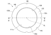
- the rod guide side spring receiver 111 has a stepped cylindrical shape composed of a cylindrical tubular portion 131 and a perforated disk-shaped flange portion 132 formed at one end of the tubular portion 131.
- the outer diameter of the flange portion 132 is larger than the outer diameter of the tubular portion 131.
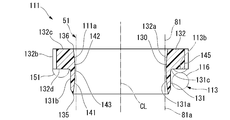
- the inner peripheral surface 111a of the rod guide side spring receiver 111 is composed of an inner peripheral surface 131a (first surface) of the tubular portion 131 and an inner peripheral surface 132a (second surface) of the flange portion 132.
- the inner peripheral surface 111a of the rod guide side spring receiver 111 has an inner peripheral surface 131a at the position of the tubular portion 131 and an inner peripheral surface 132a at the position of the flange portion 132.
- the inner peripheral surface 131a and the inner peripheral surface 132a have a shape in which one curve is swirled around the same central axis.
- the inner peripheral surface 131a and the inner peripheral surface 132a are continuous without a step.
- the inner peripheral surface 111a does not have a straight cylindrical surface portion.
- the flange portion 132 has a cylindrical surface shape in which the outer peripheral surface 132b is coaxial with the inner peripheral surface 132a.
- the flange portion 132 is formed with a recess 145 that is recessed inward in the radial direction from the outer peripheral surface 132b thereof.
- the flange portion 132 is formed with a plurality of recesses 145 at equal intervals in the circumferential direction, specifically, eight recesses 145.
- the outer diameter of the flange portion 132 (that is, the diameter of the outer peripheral surface 132b) is larger than the inner diameter of the coil spring 113.
- FIG. 1 the outer diameter of the flange portion 132 (that is, the diameter of the outer peripheral surface 132b) is larger than the inner diameter of the coil spring 113.
- the end surface 132c on the side opposite to the tubular portion 131 in the axial direction thereof extends orthogonally to the central axis of the outer peripheral surface 132b.
- the flange portion 132 also has an end surface 132d on the tubular portion 131 side in the axial direction extending orthogonally to the central axis of the outer peripheral surface 132b.
- the support-side spring receiver 112 is also formed with eight recesses as in the recess 145.
- the tubular portion 131 has a cylindrical surface whose outer peripheral surface 131b is coaxial with the inner peripheral surface 131a.
- the outer diameter of the tubular portion 131 (that is, the diameter of the outer peripheral surface 131b) is smaller than the inner diameter of the coil spring 113.
- the end of the tubular portion 131 on the flange portion 132 side in the axial direction with respect to the outer peripheral surface 131b is an R chamfered 131c.
- the inner diameter of the coil spring 113 and the outer peripheral surface 131b of the tubular portion 131 are fixed by press fitting. Therefore, in the state before assembly, the diameter of the outer peripheral surface 131b is larger than the inner diameter of the coil spring 113.
- the inner peripheral surface 111a of the rod guide side spring receiver 111 is located at an intermediate predetermined position in the axial direction of the rod guide side spring receiver 111 from the opening edge 135 at the end opposite to the flange portion 132 of the tubular portion 131 in the axial direction. It has a cylinder-side inner peripheral surface portion 141 that extends while reducing the diameter so that the diameter gradually decreases. Further, the diameter of the inner peripheral surface 111a is gradually reduced from the opening edge 136 of the end portion of the flange portion 132 opposite to the tubular portion 131 in the axial direction to the position of the inner peripheral surface portion 141 on the tubular portion side. It has an inner peripheral surface portion 142 on the flange portion side that extends while reducing the diameter.
- the inner peripheral surface 111a of the rod guide side spring receiver 111 has a boundary position between the inner peripheral surface portion 141 on the tubular portion side and the inner peripheral surface portion 142 on the flange portion side at the position of the small diameter portion 143 having the smallest diameter.
- the small diameter portion 143 aligns with the boundary position between the outer peripheral surface 131b of the tubular portion 131 and the R chamfering 131c.
- the inner peripheral surface 111a of the rod guide side spring receiver 111 has an arcuate cross section on the surface including the central axis of the rod guide side spring receiver 111, which is convex toward the central axis.
- the inner peripheral surface 111a of the rod guide side spring receiver 111 has a cross section in a plane orthogonal to the central axis of the rod guide side spring receiver 111, which is continuous over the entire circumference in the circumferential direction of the rod guide side spring receiver 111 regardless of the position. It is a circular shape. Therefore, the small diameter portion 143 is also a circular shape that is continuous over the entire circumference in the circumferential direction of the rod guide side spring receiver 111.
- the inner peripheral surface 111a of the rod guide side spring receiver 111 is provided with a small diameter portion 143 having the smallest diameter in the inner peripheral surface 131a of the tubular portion 131.
- the small diameter portion 143 having the smallest diameter overlaps the tubular portion 131 with the axial position.
- the inner peripheral surface 111a is provided with the small diameter portion 143 having the smallest diameter offset from the boundary position between the cylinder portion 131 and the flange portion 132 toward the cylinder portion 131.
- the inner peripheral surface 111a has the center of the arc of the cross section on the surface including the central axis of the rod guide side spring receiver 111 in the axial direction of the rod guide side spring receiver 111. It is provided so as to be offset toward the cylinder portion 131 side from the boundary position. In other words, in the through hole 130 of the rod guide side spring receiver 111, the small diameter portion 143 having the smallest hole diameter overlaps the tubular portion 131 in the axial direction.
- the inner peripheral surface 131a of the tubular portion 131 approaches the hole center (central axis CL) of the through hole 130 from the opening edge 135 on the tubular portion 131 side in the axial direction of the through hole 130 toward the small diameter portion 143.
- the shape is such that the through hole 130 is separated from the hole center (center axis CL) from the position of the small diameter portion 143 toward the inner peripheral surface 132a of the flange portion 132.
- the inner peripheral surface 132a of the flange portion 132 has a shape that approaches the hole center (central axis CL) of the through hole 130 from the opening edge 136 on the flange portion 132 side in the axial direction of the through hole 130 toward the small diameter portion 143. be.
- the diameter of the small diameter portion 143 which is the minimum inner diameter of the rod guide side spring receiver 111, is larger than the outer diameter of the main shaft portion 81 of the piston rod 51 (that is, the diameter of the outer peripheral surface 81a). It has become.
- the rod guide side spring receiver 111 is supported in the radial direction by the spindle portion 81 by inserting the spindle portion 81 of the piston rod 51 into the through hole 130.
- the flange portion 132 of the tubular portion 131 and the flange portion 132 is located on the side opposite to the axial stopper support 95, and the tubular portion 131 is an axial stopper. It is oriented to be located on the support 95 side.
- the rod guide side spring receiver 111 is provided so as to be movable in the axial direction with respect to the piston rod 51 and the stopper support 95.
- the tubular portion 131 is inserted inside the second end portion 116 of the coil spring 113 in the radial direction, and the second end portion 116 of the coil spring 113 is radially inside. Support from the inside. At that time, the outer peripheral surface 131b of the tubular portion 131 overlaps the inner peripheral surface of the second end portion 116 of the coil spring 113 with the axial position and faces each other in the radial direction.
- the rod guide side spring receiver 111 supported by the main shaft portion 81 hits the axially outer end surface 113b of the second end portion 116 of the coil spring 113 at the end surface 132d of the flange portion 132 on the tubular portion 131 side. In contact with the coil spring 113, it is supported from the inside in the axial direction by the second end portion 116.
- the rod guide side spring receiver 111 supported by the main shaft portion 81 has a rod guide shown in FIG. 1 at the end surface 132c of the flange portion 132 on the opposite side of the tubular portion 131 when the piston rod 51 is fully extended. It abuts on the inner end surface 26a of 26.
- the rod guide side spring receiver 111 is composed of a tubular portion 131 that supports the coil spring 113 in the radial direction and a flange portion 132 formed at the end of the tubular portion 131 as shown in FIG. Will be done.
- the inner peripheral surface 111a of the rod guide side spring receiver 111 has an inner peripheral surface 131a at the position of the tubular portion 131 and an inner peripheral surface 132a at the position of the flange portion 132.
- the inner peripheral surface 111a is formed with a small diameter portion 143 having the smallest diameter on the inner peripheral surface 131a at the position of the tubular portion 131.
- the small diameter portion 143 of the inner peripheral surface 111a of the rod guide side spring receiver 111 is positioned axially with the end strip portion 151 of the first row from the end of the second end portion 116 of the coil spring 113. It is superposed.
- the end strip 151 is a portion of the linear member 114 that constitutes the coil spring 113, which is wound once from the end on the side that constitutes the second end portion 116.
- the end strip portion 151 is a one-roll portion including the end face 113b.
- the coil spring 113 is configured to overlap the position in the axial direction with the first edge portion 151 from the end of the second end portion 116, but the configuration is not limited to this configuration, for example. It may be the second article.
- the shape of the inner peripheral surface 111a of the rod guide side spring receiver 111 is set so that when it comes into contact with the outer peripheral surface 81a of the piston rod 51, it always makes point contact, assuming that there is no deformation.
- the rod guide side spring receiver 111 is offset or tilted with respect to the shaft of the piston rod 51 due to variations in the coil spring 113, variations in assembly of the rod guide side spring receiver 111 and the support side spring receiver 112, and the like.
- the inner peripheral surface 111a a curved surface, assuming that there is no deformation, the contact state with the piston rod 51 does not become a line contact but a point contact in any case.
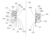
- the coil spring 113 and the rod guide side spring receiver 111 are maximized with respect to the central axis of the piston rod 51 as shown in FIG.
- it makes point contact with the outer peripheral surface 81a of the piston rod 51 at two points, a first contact point 161 on one side in the tilt direction and a second contact point 162 on the opposite side in the tilt direction.
- Both the first contact point 161 and the second contact point 162 are axially intermediate positions of the inner peripheral surface 111a of the rod guide side spring receiver 111.
- the inner peripheral surface 131a of the tubular portion 131 is the rod guide side spring.
- a gap 171 is maintained between the piston rod 51 and the outer peripheral surface 81a of the main shaft portion 81 of the piston rod 51 on the opening edge 135 side, which is one side of the first contact point 161 in the axial direction of the receiver 111.
- the inner peripheral surface 132a of the flange portion 132 is the piston rod at the opening edge 136 side which is the other side of the first contact point 161 in the axial direction of the rod guide side spring receiver 111.
- a gap 172 is maintained between the main shaft portion 81 of the 51 and the outer peripheral surface 81a.
- the inner peripheral surface 131a of the tubular portion 131 is the piston rod 51 on the opening edge 135 side, which is one side of the second contact point 162 in the axial direction of the rod guide side spring receiver 111.
- a gap 173 is maintained between the main shaft portion 81 and the outer peripheral surface 81a of the above.
- the inner peripheral surface 132a of the flange portion 132 is the piston rod 51 on the opening edge 136 side which is the other side of the second contact point 162 in the axial direction of the rod guide side spring receiver 111.
- a gap 174 is maintained between the main shaft portion 81 and the outer peripheral surface 81a of the above.
- Patent Document 1 describes a shock absorber provided with a rebound stopper mechanism that cushions the impact at the time of full extension.
- the spring receiver of this rebound stopper mechanism has a small diameter portion having a minimum hole diameter formed on the inner peripheral surface at the position of the flange portion.
- the small diameter portion at the position of the flange portion and the cylinder portion deformed by the load from the coil spring. It comes into contact with the piston rod at two points that are spaced apart from each other in the axial direction or at a line connecting them. As a result, the contact range with respect to the piston rod is expanded, and the frictional resistance is expanded.
- the piston rod 51 One rod guide side spring receiver 111 that moves in the axial direction is composed of a cylinder portion 131 that supports the coil spring 113 in the radial direction and a flange portion 132 formed at the end of the cylinder portion 131, and the inner circumference thereof. Of the surfaces 111a, a small diameter portion 143 having the smallest diameter is formed on the inner peripheral surface 131a at the position of the tubular portion 131.
- the rod guide side spring receiver 111 even if the tubular portion 131 is deformed in the radial direction due to the load from the coil spring 113, the small diameter portion 143 is formed on the inner peripheral surface 131a at the position of the tubular portion 131. Therefore, the piston rod 51 is brought into contact with the piston rod 51 in a form close to point contact. Therefore, it is possible to suppress the expansion of the contact range with respect to the piston rod 51 and the expansion of the frictional resistance. Therefore, even if the rod guide side spring receiver 111 comes into contact with the rod guide 26 due to the extension of the piston rod 51, the frictional resistance against the piston rod 51 is small, so that the rod guide side spring receiver 111 is smooth with respect to the piston rod 51. Can slide on. As a result, it is possible to suppress the generation of abnormal noise caused by tapping sound, unnecessary vibration, and the like.
- the inner peripheral surface 131a of the tubular portion 131 approaches the hole center of the through hole 130 from the opening edge 135 on the tubular portion 131 side of the through hole 130 toward the small diameter portion 143.
- the inner peripheral surface 132a of the flange portion 132 has a shape that approaches the hole center of the through hole 130 from the opening edge 136 on the flange portion 132 side of the through hole 130 toward the small diameter portion 143. Therefore, it is possible to suppress the expansion of the contact range with respect to the piston rod 51 and the expansion of the frictional resistance due to the fall of the rod guide side spring receiver 111. Therefore, the rod guide side spring receiver 111 can slide smoothly with respect to the piston rod 51. Therefore, it is possible to suppress the generation of abnormal noise caused by tapping sound, unnecessary vibration, and the like.
- the inner peripheral surface 111a of the rod guide side spring receiver 111 has a shape in which the cross section of the surface including the central axis of the rod guide side spring receiver 111 is smoothly curved so that the small diameter portion 143 is closest to the central axis.
- the shape of the inner peripheral surface 111a is set so that when it comes into contact with the outer peripheral surface 81a of the piston rod 51, it always makes point contact, assuming that there is no deformation. Therefore, it is possible to further suppress the expansion of the contact range with respect to the piston rod 51 and the expansion of the frictional resistance due to the tilting of the rod guide side spring receiver 111. Therefore, the rod guide side spring receiver 111 can slide smoothly with respect to the piston rod 51. As a result, it is possible to suppress the generation of abnormal noise caused by tapping sound, unnecessary vibration, and the like.
- the inner peripheral surface 111a of the rod guide side spring receiver 111 is a curved surface. Therefore, the inner peripheral surface 111a is in contact with the piston rod 51 even if it is deformed at the moment when the rod guide side spring receiver 111 comes into contact with the rod guide 26, or after the contact, while sliding along the piston rod 51. Is a shape close to point contact. Therefore, the contact state between the inner peripheral surface 111a of the rod guide side spring receiver 111 and the piston rod 51 is stable in a form close to point contact. Therefore, it is possible to suppress stick slip and drag that occur when the contact state becomes unstable. Therefore, unnecessary vibration is not transmitted to the piston rod 51. Therefore, it is possible to suppress abnormal noise and the like generated on the vehicle side due to vibration.
- the inner peripheral surface 131a of the tubular portion 131 of the rod guide side spring receiver 111 and the inner peripheral surface 132a of the flange portion 132 have the piston rod 51 even when the axis of the coil spring 113 is tilted with respect to the axis of the piston rod 51.
- the gap 171, 172, 173, 174 with the outer peripheral surface 81a of the above is maintained. Therefore, it is possible to further suppress the expansion of the contact range of the rod guide side spring receiver 111 with respect to the piston rod 51 and the expansion of the frictional resistance due to the tilting of the coil spring 113. Therefore, the rod guide side spring receiver 111 can slide smoothly with respect to the piston rod 51. Therefore, it is possible to further suppress the generation of abnormal noise caused by tapping sound, unnecessary vibration, and the like.
- the small diameter portion 143 overlaps the axial position with the first end strip portion 151 of the coil spring 113. Therefore, it is possible to further suppress the expansion of the contact range of the rod guide side spring receiver 111 with respect to the piston rod 51 and the expansion of the frictional resistance due to the load from the coil spring 113. Therefore, the rod guide side spring receiver 111 can slide more smoothly with respect to the piston rod 51. Therefore, it is possible to further suppress the generation of abnormal noise caused by tapping sound, unnecessary vibration, and the like.
- rod guide side spring receiver 111 and the support side spring receiver 112 one rod guide side spring receiver that moves with respect to the piston rod 51 instead of the support side spring receiver 112 fixed to the piston rod 51. 111 has the above configuration. Therefore, it is possible to effectively suppress the generation of abnormal noise caused by tapping sound, unnecessary vibration, and the like.
- the rod guide side spring receiver 111 when the central axis of the rod guide side spring receiver 111 is greatly inclined with respect to the central axis CL of the piston rod 51 due to the inclination of the coil spring 113 and the variation in the parallelism of the upper and lower end faces 113a and 113b, the rod guide side spring The inner peripheral surface 111a of the receiver 111 comes into contact with the piston rod 51 at the first contact point 161 and the second contact point 162 located diagonally thereof. At that time, the axial distance between the first contact point 161 and the second contact point 162 can be reduced, and the action of the moment can be suppressed to be small. As a result, the contact resistance that causes abnormal noise can be further reduced.
- the inner peripheral surface 111a of the rod guide side spring receiver 111 is expanded in diameter from the small diameter portion 143 in the middle in the axial direction toward the opening edges 135 and 136 at both ends in the axial direction, the shaft of the rod guide side spring receiver 111 Wide tolerance for tilt. Therefore, the inclination of the coil spring 113 and the tolerance of the coaxiality can be relaxed, and the cost can be reduced.
- the rod guide side spring receiver 111 is made of synthetic resin and can be molded with a mold. Therefore, the decrease in productivity can be suppressed. In that case, by locating the parting line at the time of molding on the small diameter portion 143, it is possible to obtain the same productivity as the conventional product.
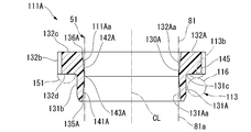
- the rod guide side spring receiver 111A (first spring receiver) which is partially different from the rod guide side spring receiver 111 of the first embodiment shown in FIG. 4 have.
- the rod guide side spring receiver 111A has an inner peripheral surface 111Aa having a shape different from the inner peripheral surface 111a of the rod guide side spring receiver 111.
- the rod guide side spring receiver 111A has a through hole 130A having a shape different from that of the through hole 130 with respect to the rod guide side spring receiver 111.
- the rod guide side spring receiver 111A differs from the rod guide side spring receiver 111 in that it has an inner peripheral surface 131Aa (first surface) having a shape different from that of the inner peripheral surface 131a. Have. Further, the rod guide side spring receiver 111A is different in that the flange portion 132 of the rod guide side spring receiver 111 has an inner peripheral surface 132Aa (second surface) having a shape different from the inner peripheral surface 132a thereof. It has 132A.
- the inner peripheral surface 111Aa of the rod guide side spring receiver 111A is located at an intermediate predetermined position in the axial direction of the rod guide side spring receiver 111A from the opening edge 135A at the end opposite to the flange portion 132A of the tubular portion 131A in the axial direction. It has a tapered cylinder-side inner peripheral surface portion 141A that extends while reducing the diameter so that the diameter gradually decreases. Further, the diameter of the inner peripheral surface 111Aa is gradually reduced from the opening edge 136A at the end of the flange portion 132A opposite to the tubular portion 131A in the axial direction to the position of the tubular portion side inner peripheral surface portion 141A. It has a tapered flange-side inner peripheral surface portion 142A that extends while reducing the diameter.
- the inner peripheral surface portion 141A on the tubular portion side is a tapered surface coaxial with the outer peripheral surface 131b of the tubular portion 131A.
- the flange portion side inner peripheral surface portion 142A is a tapered surface coaxial with the outer peripheral surface 132b of the flange portion 132A.
- the inner peripheral surface 111Aa of the rod guide side spring receiver 111A has a small diameter portion 143A at which the boundary position between the inner peripheral surface portion 141A on the tubular portion side and the inner peripheral surface portion 142A on the flange portion side is the minimum.
- the small diameter portion 143A is a circular shape continuous over the entire circumference in the circumferential direction of the rod guide side spring receiver 111A.
- the inner peripheral surface 111Aa of the rod guide side spring receiver 111A is provided with a small diameter portion 143A having the smallest diameter in the inner peripheral surface 131Aa of the tubular portion 131A.
- the small diameter portion 143A having the smallest diameter overlaps the tubular portion 131A in the axial direction.
- the inner peripheral surface 111Aa is provided with the small diameter portion 143A having the smallest diameter offset from the boundary position between the tubular portion 131A and the flange portion 132A toward the tubular portion 131A.
- the small diameter portion 143A having the smallest hole diameter overlaps the tubular portion 131A in the axial direction.
- the inner peripheral surface 131Aa of the tubular portion 131A approaches the hole center of the through hole 130A from the opening edge 135A on the tubular portion 131A side in the axial direction toward the small diameter portion 143A, and then from the position of the small diameter portion 143A. It has a shape that moves away from the hole center of the through hole 130A toward the inner peripheral surface 132Aa of the flange portion 132A.
- the inner peripheral surface 132Aa of the flange portion 132A has a shape that approaches the hole center of the through hole 130A from the opening edge 136A on the flange portion 132A side in the axial direction of the through hole 130A toward the small diameter portion 143A.
- the small diameter portion 143A aligns with the boundary position between the outer peripheral surface 131b of the tubular portion 131A and the R chamfering 131c.
- the diameter of the small diameter portion 143A is larger than the outer diameter of the main shaft portion 81 of the piston rod 51 (that is, the diameter of the outer peripheral surface 81a).
- the rod guide side spring receiver 111A is also composed of a tubular portion 131A that supports the coil spring 113 in the radial direction and a flange portion 132A formed at the end of the tubular portion 131A.
- the inner peripheral surface 111Aa of the rod guide side spring receiver 111A has an inner peripheral surface 131Aa at the position of the tubular portion 131A and an inner peripheral surface 132Aa at the position of the flange portion 132A.
- the inner peripheral surface 111Aa is formed with a small diameter portion 143A having the smallest diameter on the inner peripheral surface 131Aa at the position of the tubular portion 131A.
- the small diameter portion 143A overlaps the position in the axial direction with the end strip portion 151 of the first row from the end of the second end portion 116 of the coil spring 113.
- the shape of the inner peripheral surface 111Aa of the rod guide side spring receiver 111A is set so that when it comes into contact with the outer peripheral surface 81a of the piston rod 51, it always makes point contact at the small diameter portion 143A, assuming that there is no deformation. There is. In other words, the rod guide side spring receiver 111A may be offset or tilted with respect to the shaft of the piston rod 51. However, assuming that there is no deformation by forming the inner peripheral surface 111Aa into a bent shape, the contact state with the piston rod 51 becomes a point contact at the small diameter portion 143A in any case. The piston rod 51 and the small diameter portion 143A come into contact with each other even when the central axes of the coil spring 113 and the rod guide side spring receiver 111A are tilted with respect to the central axis of the piston rod 51.
- the rod guide side spring receiver 111A is assumed to have no deformation, and the small diameter portion 143A.
- the piston rod 51 makes point contact with the outer peripheral surface 81a.
- the inner peripheral surface 131Aa of the tubular portion 131A is a piston at the opening edge 135A side which is one side of the contact point and the opening edge 136A side which is the other side in the axial direction of the rod guide side spring receiver 111A.
- a gap is maintained between the rod 51 and the outer peripheral surface 81a of the main shaft portion 81.
- the inner peripheral surface 132Aa of the flange portion 132A is the main shaft portion 81 of the piston rod 51 only on the opening edge 136A side which is the other side of the contact point in the axial direction of the rod guide side spring receiver 111.
- a gap is maintained between the outer peripheral surface 81a and the outer peripheral surface 81a.
- the rod guide side spring receiver 111A described above comes into contact with the piston rod 51 when its small diameter portion 143A is tilted with respect to the central axis of the piston rod 51. Therefore, even when the coil spring 113 is tilted with respect to the piston rod 51, the rod guide side spring receiver 111A can be stably brought into contact with the piston rod 51 at the small diameter portion 143A.
- the diameter of the outer peripheral surface 81a of the main shaft portion 81 of the piston rod 51 is set to be equal to or larger than the diameter of the small diameter portion 143A, and the piston rod 51 is fitted to the small diameter portion 143A. You can do it.
- the piston rod 51 and the small diameter portion 143A have a portion where they are in constant contact with each other. As a result, the contact state between the piston rod 51 and the rod guide side spring receiver 111A can be stabilized. Therefore, it is possible to suppress fluctuations in the sliding state of the rod guide side spring receiver 111A with respect to the piston rod 51. Therefore, the generation of abnormal noise can be suppressed.
- the rod guide side spring receiver 111A when the rod guide side spring receiver 111A is tilted with respect to the piston rod 51, the rod is in the cross-sectional position on the surface including the central axis of the piston rod 51 and the central axis of the rod guide side spring receiver 111A. Assuming that the guide-side spring receiver 111A is not deformed, it makes point contact with the piston rod 51.
- the configuration in which the piston rod 51 and the small diameter portion 143A are constantly in contact with each other is not limited to the second embodiment, and may be applied to other embodiments.
- the rod guide side spring receiver 111B (first spring receiver) which is partially different from the rod guide side spring receiver 111 of the first embodiment shown in FIG. 4 have.
- the rod guide side spring receiver 111B has an inner peripheral surface 111Ba having a shape different from the inner peripheral surface 111a of the rod guide side spring receiver 111.
- the rod guide side spring receiver 111B has a through hole 130B having a shape different from that of the through hole 130 with respect to the rod guide side spring receiver 111.
- the rod guide side spring receiver 111B has a tubular portion 131B different from the tubular portion 131 in that it has an inner peripheral surface 131Ba (first surface) having a shape different from that of the inner peripheral surface 131a. Further, the rod guide side spring receiver 111B has a flange portion 132B different from the flange portion 132 in that it has an inner peripheral surface 132Ba (second surface) having a shape different from that of the inner peripheral surface 132a.
- the inner peripheral surface 111Ba of the rod guide side spring receiver 111B is located at an intermediate predetermined position in the axial direction of the rod guide side spring receiver 111B from the opening edge 135B at the end opposite to the flange portion 132B of the cylindrical portion 131B in the axial direction. It has a cylindrical surface-shaped inner peripheral surface portion 141B on the tubular portion side having a constant diameter formed up to. Further, the inner peripheral surface 111Ba of the rod guide side spring receiver 111B is intermediate from the opening edge 136B at the end opposite to the cylindrical portion 131B of the flange portion 132B in the axial direction in the axial direction of the rod guide side spring receiver 111B.
- the inner peripheral surface portion 141B on the tubular portion side and the inner peripheral surface portion 142B on the flange portion side may have the same inner peripheral surface from one end to the other end, or may have a tapered shape.
- the inner peripheral surface portion 141B on the tubular portion side is a cylindrical surface coaxial with the outer peripheral surface 131b of the tubular portion 131B.
- the flange portion side inner peripheral surface portion 142B is a cylindrical surface coaxial with the outer peripheral surface 132b of the flange portion 132B.
- the inner peripheral surface portion 141B on the tubular portion side and the inner peripheral surface portion 142B on the flange portion side are cylindrical surfaces having the same coaxial diameter.
- the inner peripheral surface 111Ba of the rod guide side spring receiver 111B is an annular inner protruding portion 201 projecting inward in the radial direction between the tubular portion side inner peripheral surface portion 141B and the flange portion side inner peripheral surface portion 142B. have.
- the inner protruding portion 201 is shrunk so that the diameter gradually decreases from the end edge portion of the inner peripheral surface portion 141B on the tubular portion side on the flange portion side inner peripheral surface portion 142B side to an intermediate predetermined position on the flange portion side inner peripheral surface portion 142B side. It has a tapered inner peripheral surface portion 202 that extends while having a diameter.
- the inner protruding portion 201 is reduced in diameter so that the diameter gradually decreases from the end edge portion of the flange portion side inner peripheral surface portion 142B on the tubular portion side inner peripheral surface portion 141B side to the position of the inclined inner peripheral surface portion 202. It has a tapered inclined inner peripheral surface portion 203 that extends.
- the inclined inner peripheral surfaces 202 and 203 have mirror-symmetrical shapes with each other, and are tapered surfaces coaxial with the outer peripheral surface 131b of the tubular portion 131B, respectively.
- the inner peripheral surface 111Ba of the rod guide side spring receiver 111B has a small diameter portion 143B at which the boundary position between the inclined inner peripheral surface portion 202 and the inclined inner peripheral surface portion 203 is the minimum.
- the small diameter portion 143B is a circular shape that is continuous over the entire circumference of the rod guide side spring receiver 111B in the circumferential direction.
- the small diameter portion 143B has a constant radial distance from the inner peripheral surface portion 141B on the tubular portion side and the inner peripheral surface portion 142B on the flange portion side over the entire circumference in the circumferential direction.
- the inner peripheral surface 111Ba of the rod guide side spring receiver 111B has a small diameter portion 143B having the smallest diameter provided in the inner peripheral surface 131Ba of the tubular portion 131B.
- the small diameter portion 143B having the smallest diameter overlaps the tubular portion 131B in the axial direction.
- the inner peripheral surface 111Ba is provided with the small diameter portion 143B having the smallest diameter offset from the boundary position between the tubular portion 131B and the flange portion 132B toward the tubular portion 131B.
- the small diameter portion 143B having the smallest hole diameter overlaps the tubular portion 131B in the axial direction.
- the small diameter portion 143B aligns with the boundary position between the outer peripheral surface 131b of the tubular portion 131B and the R chamfer 131c.
- the diameter of the small diameter portion 143B is larger than the outer diameter of the main shaft portion 81 of the piston rod 51 (that is, the diameter of the outer peripheral surface 81a).
- the rod guide side spring receiver 111B is also composed of a tubular portion 131B that supports the coil spring 113 in the radial direction and a flange portion 132B formed at the end of the tubular portion 131B.
- the inner peripheral surface 111Ba of the rod guide side spring receiver 111B has an inner peripheral surface 131Ba at the position of the tubular portion 131B and an inner peripheral surface 132Ba at the position of the flange portion 132B.
- the inner peripheral surface 111Ba is formed with a small diameter portion 143B having the smallest diameter on the inner peripheral surface 131Ba at the position of the tubular portion 131B.
- the small diameter portion 143B overlaps the position in the axial direction with the end strip portion 151 of the first row from the end of the second end portion 116 of the coil spring 113.
- the shape of the inner peripheral surface 111Ba of the rod guide side spring receiver 111B is set so that when it comes into contact with the outer peripheral surface 81a of the piston rod 51, it always makes point contact at the small diameter portion 143B, assuming that there is no deformation. There is. In other words, the rod guide side spring receiver 111B may be offset or tilted with respect to the shaft of the piston rod 51.
- the contact state with the piston rod 51 becomes the point contact in the small diameter portion 143B in any case. ..
- the piston rod 51 and the small diameter portion 143B come into contact with each other when the central axes of the coil spring 113 and the rod guide side spring receiver 111B are tilted with respect to the central axis of the piston rod 51.
- the rod guide side spring receiver 111B has a small diameter portion 143B, assuming that there is no deformation.
- the contact point is set to make point contact with the outer peripheral surface 81a of the piston rod 51.
- the inner peripheral surface 131Ba of the tubular portion 131B is on the opening edge 135B side, which is one side of the contact point, and the opening edge 136B side, which is the other side, in the axial direction of the rod guide side spring receiver 111B.
- a gap is maintained between the piston rod 51 and the outer peripheral surface 81a of the main shaft portion 81.
- the inner peripheral surface 132Ba of the flange portion 132B is the main shaft of the piston rod 51 only on the opening edge 136B side, which is the other side of the contact point, in the axial direction of the rod guide side spring receiver 111B.
- a gap is maintained between the portion 81 and the outer peripheral surface 81a.
- the rod guide side spring receiver 111B described above comes into contact with the piston rod 51 when its small diameter portion 143B is tilted with respect to the central axis of the piston rod 51. Therefore, even when the coil spring 113 is tilted with respect to the piston rod 51, the rod guide side spring receiver 111B can be stably brought into contact with the piston rod 51 at the small diameter portion 143B.
- the diameter of the outer peripheral surface 81a of the main shaft portion 81 of the piston rod 51 is set to be equal to or larger than the diameter of the small diameter portion 143B, and the piston rod 51 is fitted to the small diameter portion 143B. You can do it.
- the piston rod 51 and the small diameter portion 143B have a portion where they are in constant contact with each other. As a result, the contact state between the piston rod 51 and the rod guide side spring receiver 111B can be stabilized. Therefore, since the fluctuation of the sliding state of the rod guide side spring receiver 111B with respect to the piston rod 51 can be suppressed, the generation of abnormal noise can be suppressed.
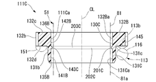
- the rod guide side spring receiver 111C (first spring receiver) which is partially different from the rod guide side spring receiver 111B of the third embodiment shown in FIG. 8 have.
- the rod guide side spring receiver 111C has an inner peripheral surface 111Ca having a shape partially different from the inner peripheral surface 111Ba thereof with respect to the rod guide side spring receiver 111B.
- the rod guide side spring receiver 111C has a through hole 130C having a shape partially different from that of the rod guide side spring receiver 111B.
- the rod guide side spring receiver 111C differs from the rod guide side spring receiver 111B in that it has an inner peripheral surface 131Ca (first surface) having a shape partially different from the inner peripheral surface 131Ba thereof. It has 131C.
- the inner peripheral surface 111Ca of the rod guide side spring receiver 111C protrudes inward in the radial direction between the tubular inner peripheral surface 141B and the flange side inner peripheral 142B as in the third embodiment. It has an annular inwardly projecting portion 201C.
- the inner protruding portion 201C is shrunk so that the diameter gradually decreases from the end edge portion of the inner peripheral surface portion 141B on the tubular portion side on the flange portion side inner peripheral surface portion 142B side to an intermediate predetermined position on the flange portion side inner peripheral surface portion 142B side. It has a curved inner peripheral surface portion 202C that extends while having a diameter.
- the inner protruding portion 201C extends from the end edge portion on the tubular portion side inner peripheral surface portion 141B side of the flange portion side inner peripheral surface portion 142B to the position of the curved inner peripheral surface portion 202C while gradually reducing the diameter. It has a curved inner peripheral surface portion 203C to be projected.
- the curved inner peripheral surface portions 202C and 203C have mirror plane symmetry with each other, and the cross section on the surface including the central axis of the rod guide side spring receiver 111C is semicircular on both sides.
- the inner peripheral surface 111Ca of the rod guide side spring receiver 111C has a small diameter portion 143C at which the boundary position between the curved inner peripheral surface portion 202C and the curved inner peripheral surface portion 203C is the minimum.
- the small diameter portion 143C is a circular shape continuous over the entire circumference in the circumferential direction of the rod guide side spring receiver 111C.
- the small diameter portion 143C has a constant radial distance from the inner peripheral surface portion 141B on the tubular portion side and the inner peripheral surface portion 142B on the flange portion side over the entire circumference.
- the inner peripheral surface 111Ca of the rod guide side spring receiver 111C has a small diameter portion 143C having the smallest diameter provided in the inner peripheral surface 131Ca of the tubular portion 131C.
- the small diameter portion 143C having the smallest diameter overlaps the tubular portion 131C in the axial direction.
- the inner peripheral surface 111Ca is provided with the small diameter portion 143C having the smallest diameter offset from the boundary position between the tubular portion 131C and the flange portion 132B toward the tubular portion 131C.
- the small diameter portion 143C having the smallest hole diameter overlaps the tubular portion 131C in the axial direction.
- the small diameter portion 143C aligns with the boundary position between the outer peripheral surface 131b of the tubular portion 131C and the R chamfering 131c.
- the diameter of the small diameter portion 143C is larger than the outer diameter of the main shaft portion 81 of the piston rod 51 (that is, the diameter of the outer peripheral surface 81a).
- the rod guide side spring receiver 111C is also composed of a tubular portion 131C that supports the coil spring 113 in the radial direction and a flange portion 132B formed at the end of the tubular portion 131C.
- the inner peripheral surface 111Ca of the rod guide side spring receiver 111C has an inner peripheral surface 131Ca at the position of the tubular portion 131C and an inner peripheral surface 132Ba at the position of the flange portion 132B.
- the inner peripheral surface 111Ca has a small diameter portion 143C having a minimum diameter formed on the inner peripheral surface 131Ca at the position of the tubular portion 131C.
- the small diameter portion 143C overlaps the position in the axial direction with the end strip portion 151 of the first row from the end of the second end portion 116 of the coil spring 113.
- the shape of the inner peripheral surface 111Ca of the rod guide side spring receiver 111C is set so that when it comes into contact with the outer peripheral surface 81a of the piston rod 51, it always makes point contact at the inner protruding portion 201C, assuming that there is no deformation. ing.
- the rod guide side spring receiver 111C may be offset or tilted with respect to the shaft of the piston rod 51.
- the contact state with the piston rod 51 is the point contact at the inner protruding portion 201C in any case. It becomes.
- the piston rod 51 and the inner protrusion 201C come into contact with each other when the central axes of the coil spring 113 and the rod guide side spring receiver 111C are tilted with respect to the central axis of the piston rod 51.
- the rod guide side spring receiver 111C is an inward protruding portion, assuming that there is no deformation.
- the contact point of 201C is set to make point contact with the outer peripheral surface 81a of the piston rod 51.
- the inner peripheral surface 131Ca of the tubular portion 131C is located on the opening edge 135B side, which is one side of the contact point, and the opening edge 136B side, which is the other side, in the axial direction of the rod guide side spring receiver 111C.
- a gap is maintained between the piston rod 51 and the outer peripheral surface 81a of the main shaft portion 81.
- the inner peripheral surface 132Ba of the flange portion 132B is the main shaft portion of the piston rod 51 only on the opening edge 136B side, which is the other side of the contact point, in the axial direction of the rod guide side spring receiver 111C.
- a gap is maintained between the 81 and the outer peripheral surface 81a.
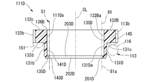
- the rod guide side spring receiver 111D (first spring receiver) which is partially different from the rod guide side spring receiver 111C of the fourth embodiment shown in FIG. 10 have.
- the rod guide side spring receiver 111D has an inner peripheral surface 111Da having a shape partially different from the inner peripheral surface 111Ca thereof with respect to the rod guide side spring receiver 111C.
- the rod guide side spring receiver 111D has a through hole 130D having a shape partially different from that of the rod guide side spring receiver 111C.
- the rod guide side spring receiver 111D has a tubular portion 131D different from the tubular portion 131C in that it has an inner peripheral surface 131Da (first surface) having a shape partially different from that of the inner peripheral surface 131Ca.
- the inner peripheral surface 111Da of the rod guide side spring receiver 111D has an opening edge 136B at an end opposite to the tubular portion 131D of the flange portion 132B in the axial direction, and the tubular portion 131D in the axial direction of the rod guide side spring receiver 111D. It has a cylindrical main inner peripheral surface portion 141D having a constant diameter formed up to an intermediate predetermined position on the opening edge 135D side at the end portion opposite to the flange portion 132B of the above.
- the main inner peripheral surface portion 141D is a cylindrical surface coaxial with the outer peripheral surface 131b of the tubular portion 131D and the outer peripheral surface 132b of the flange portion 132B.
- the inner peripheral surface 111Da of the rod guide side spring receiver 111D has an annular inner protruding portion 201D that protrudes inward in the radial direction from the main inner peripheral surface portion 141D.
- the inner protruding portion 201D extends from the opening edge 135D to an intermediate predetermined position on the main inner peripheral surface portion 141D side in the axial direction of the rod guide side spring receiver 111D while gradually reducing the diameter. It has a face portion 202D.
- the inner protruding portion 201D extends from the end edge portion of the main inner peripheral surface portion 141D opposite to the opening edge 136B to the position of the curved inner peripheral surface portion 202D while gradually reducing the diameter. It has a curved inner peripheral surface portion 203D.
- the curved inner peripheral surface portions 202D and 203D have mirror plane symmetry with each other, and the cross section on the surface including the central axis of the rod guide side spring receiver 111D is semicircular on both sides.
- the inner peripheral surface 111Da of the rod guide side spring receiver 111D has a small diameter portion 143D at which the boundary position between the curved inner peripheral surface portion 202D and the curved inner peripheral surface portion 203D is the minimum.
- the small diameter portion 143D is a circular shape continuous over the entire circumference in the circumferential direction of the rod guide side spring receiver 111D.
- the small diameter portion 143D has a constant radial distance from the main inner peripheral surface portion 141D over the entire circumference.
- the inner peripheral surface 111Da of the rod guide side spring receiver 111D has a small diameter portion 143D having the smallest diameter provided in the inner peripheral surface 131Da of the tubular portion 131D.
- the small diameter portion 143D having the smallest diameter overlaps the tubular portion 131D in the axial direction.
- the inner peripheral surface 111Da is provided with the small diameter portion 143D having the smallest diameter offset from the boundary position between the tubular portion 131D and the flange portion 132D to the tubular portion 131D side.
- the small diameter portion 143D having the smallest hole diameter overlaps the tubular portion 131D in the axial direction.
- the diameter of the small diameter portion 143D is larger than the outer diameter of the main shaft portion 81 of the piston rod 51 (that is, the diameter of the outer peripheral surface 81a).
- the rod guide side spring receiver 111D is also composed of a tubular portion 131D that supports the coil spring 113 in the radial direction and a flange portion 132B formed at the end of the tubular portion 131D.
- the inner peripheral surface 111Da of the rod guide side spring receiver 111D has an inner peripheral surface 131Da at the position of the tubular portion 131D and an inner peripheral surface 132Ba at the position of the flange portion 132B.
- the inner peripheral surface 111Da has a small diameter portion 143D having the smallest diameter formed on the inner peripheral surface 131Da at the position of the tubular portion 131D.
- the shape is set so that when it comes into contact with the outer peripheral surface 81a of the piston rod 51, it always makes point contact with the inner protruding portion 201D.
- the rod guide side spring receiver 111D may be offset or tilted with respect to the shaft of the piston rod 51.
- the contact state with the piston rod 51 is the point contact at the inner protruding portion 201D in any case. It becomes.
- the piston rod 51 and the inner protrusion 201D come into contact with each other when the central axes of the coil spring 113 and the rod guide side spring receiver 111D are tilted with respect to the central axis of the piston rod 51.
- the rod guide side spring receiver 111D is an inward protruding portion, assuming that there is no deformation.
- the piston rod 51 makes point contact with the outer peripheral surface 81a.
- the inner peripheral surface 131Da of the tubular portion 131D is located on the opening edge 135D side, which is one side of the contact point, and the opening edge 136B side, which is the other side, in the axial direction of the rod guide side spring receiver 111D.
- a gap is maintained between the piston rod 51 and the outer peripheral surface 81a of the main shaft portion 81.
- the inner peripheral surface 132Ba of the flange portion 132B is the main shaft portion of the piston rod 51 only on the opening edge 136B side, which is the other side of the contact point, in the axial direction of the rod guide side spring receiver 111D.
- a gap is maintained between the 81 and the outer peripheral surface 81a.
- the small diameter portions 143, 143A, 143B, 143C, and 143D all form a continuous circular shape has been described as an example.
- the small diameter portions 143, 143A, 143B, 143C, and 143D may be formed intermittently in the circumferential direction. As a result, the weight of the rod guide side spring receivers 111, 111A, 111B, 111C, 111D can be reduced.
- the rod guide side spring receiver 111B of the fourth embodiment shown in FIGS. 8 and 9 has a small diameter portion 143B, an inclined inner peripheral surface portion 202, and an inclined inner peripheral surface portion, all of which are continuously formed over the entire circumference.
- the inner peripheral surface 131Ba having the inner protruding portion 201 including 203, the tubular portion 131B provided with the inner peripheral surface 131B, the inner peripheral surface 111Ba, and the through hole 130B are all intermittently formed in the circumferential direction.
- An inner peripheral surface 131Ea having an inner protruding portion 201E including a small diameter portion 143E, an inclined inner peripheral surface portion 202E, and an inclined inner peripheral surface portion 203E, and a tubular portion 131E, an inner peripheral surface 111Ea, and a through hole 130E provided with the inner peripheral surface 131Ea.
- the rod guide side spring receiver 111E may be used. However, when the central axis of the coil spring 113 and the rod guide side spring receiver 111E is tilted with respect to the central axis of the piston rod 51, the rod guide side spring receiver 111E always has the small diameter portion 143E and the outer peripheral surface 81a of the piston rod 51. Make contact with.
- the support side spring receiver 112 is maintained in contact with the stopper support 95, and the rod guide side spring receivers 111, 111A to 111E are in contact with the rod guide 26. It is a structure that moves in the axial direction to abut and separate.
- the rod guide side spring receiver 111F is maintained in contact with the rod guide 26, and the support side spring receiver 112F is a stopper support. It has a structure that moves in the axial direction with respect to 95 to abut and separate from each other.
- the shock absorber 11F has a rebound stopper mechanism 101F that is partially different from the rebound stopper mechanism 101.
- the coil spring 113F spirals a metal linear member 114F having a rectangular cross-sectional shape on a plane orthogonal to the extending direction so as to form a cylindrical shape having a constant inner diameter and a constant outer diameter as a whole. It is wound in a shape.
- the first end portion 115F of the coil spring 113F is fitted into the tubular portion 121F until it comes into contact with the flange portion 122F, and is fixed to the support side spring receiver 112F.
- the second end portion 116F of the coil spring 113F is fitted into the tubular portion 131F until it comes into contact with the flange portion 132F, and is fixed to the rod guide side spring receiver 111F.
- the rod guide side spring receiver 111F maintains a state in which the flange portion 132F is locked to the locking portion 211 of the inner cylinder 15F and comes into contact with the rod guide 26.
- the inner peripheral surface of the support-side spring receiver 112F that moves axially with respect to the stopper support 95 to abut and separate from the stopper support 95 is the inner peripheral surface of the first to fifth embodiments.
- the configuration is the same as any one of the inner peripheral surfaces 111a, 111Aa, 111Ba, 111Ca, 111Da of the rod guide side spring receivers 111, 111A to 111D.
- the small diameter portions 143, 143A to 143D may be formed intermittently in the circumferential direction as in the above modification.
- the rod guide side spring receiver and the support side spring Both inner peripheral surfaces of the receiver have the same configuration as any one of the inner peripheral surfaces 111a, 111Aa, 111Ba, 111Ca, 111Da of the rod guide side spring receivers 111, 111A to 111D of the first to fifth embodiments. do.
- the small diameter portions 143, 143A to 143D may be formed intermittently in the circumferential direction as in the above modification.
- both the rod guide side spring receiver and the support side spring receiver can be used.
- the inner surface can be curved. In that case, variations such as the inclination of the coil spring can be more tolerated.
- the shock absorber includes a cylinder in which a working fluid is sealed, a spring that is slidably fitted in the cylinder, and one end side connected to the piston.
- a piston rod whose end side extends to the outside of the cylinder and a rebound stopper mechanism that limits the extension of the piston rod from the cylinder are provided, and the rebound stopper mechanism is provided on the other end side of the piston rod.
- a first spring receiver, a second spring receiver provided on one end side of the piston rod, and a coil spring provided between the first spring receiver and the second spring receiver are provided.
- the spring receiver which is at least one of the first spring receiver and the second spring receiver, is composed of a tubular portion that supports the coil spring and a flange portion formed at the end of the tubular portion.
- the inner peripheral surface of the spring receiver has a first surface at the position of the tubular portion and a second surface at the position of the flange portion, and the small diameter portion having the minimum diameter on the first surface. Is formed. According to the above configuration, it is possible to suppress the generation of abnormal noise.
- the first surface has a shape in which the first surface approaches the center of the hole from the opening edge on the tubular portion side toward the small diameter portion, and the second aspect is described.
- the surface has a shape that approaches the center of the hole from the opening edge on the flange portion side toward the small diameter portion.
- the piston Maintain a gap with the outer peripheral surface of the rod.
- the position of the small diameter portion overlaps with the first line of the coil spring and the position in the axial direction.
- the first spring receiver is movably provided with respect to the piston rod, and the second spring receiver is the piston rod.
- the first spring receiver is the spring receiver.
- the sixth aspect has a portion where the piston rod and the small diameter portion are in constant contact with each other in any one of the first to fifth aspects.
- the piston rod and the small diameter portion come into contact with each other when the axis of the coil spring is tilted with respect to the axis of the piston rod. There is.
Landscapes
- Engineering & Computer Science (AREA)
- General Engineering & Computer Science (AREA)
- Mechanical Engineering (AREA)
- Fluid-Damping Devices (AREA)
Abstract
この緩衝器は、シリンダと、ピストンと、ピストンロッドと、リバウンドストッパ機構と、を備える。前記リバウンドストッパ機構は、第1のバネ受と、第2のバネ受と、前記第1のバネ受と前記第2のバネ受との間に設けられるコイルスプリングと、を備える。前記第1のバネ受および前記第2のバネ受のうちの少なくとも一方であるバネ受が、前記コイルスプリングを支持する筒部と前記筒部の端に形成されるフランジ部とから構成される。前記バネ受の内周面が、前記筒部の位置にある第1の面と、前記フランジ部の位置にある第2の面とを有し、前記第1の面に径が最小となる小径部が形成されている。
Description
本発明は、緩衝器に関する。
本願は、2020年1月28日に、日本国に出願された特願2020-011492号に基づき優先権を主張し、その内容をここに援用する。
本願は、2020年1月28日に、日本国に出願された特願2020-011492号に基づき優先権を主張し、その内容をここに援用する。
伸び切り時の衝撃を緩和するリバウンドストッパ機構を備えた緩衝器がある(例えば、特許文献1参照)。
緩衝器において異音の発生を抑制する要望がある。
したがって、本発明は、異音の発生を抑制することが可能となる緩衝器の提供を目的とする。
上記目的を達成するために、本発明は以下の態様を採用した。
すなわち、本発明の一態様に係る緩衝器は、作動流体が封入されるシリンダと、前記シリンダ内に摺動可能に嵌装されるピストンと、一端側が前記ピストンに連結され他端側が前記シリンダの外部へ延出されるピストンロッドと、前記ピストンロッドの、前記シリンダからの伸長を制限するリバウンドストッパ機構と、を備え、前記リバウンドストッパ機構が、前記ピストンロッドの他端側に設けられる第1のバネ受と、前記ピストンロッドの一端側に設けられる第2のバネ受と、前記第1のバネ受と前記第2のバネ受との間に設けられるコイルスプリングと、を備え、前記第1のバネ受および前記第2のバネ受のうちの少なくとも一方であるバネ受が、前記コイルスプリングを支持する筒部と前記筒部の端に形成されるフランジ部とから構成され、前記バネ受の内周面が、前記筒部の位置にある第1の面と、前記フランジ部の位置にある第2の面とを有し、前記第1の面に径が最小となる小径部が形成されている。
すなわち、本発明の一態様に係る緩衝器は、作動流体が封入されるシリンダと、前記シリンダ内に摺動可能に嵌装されるピストンと、一端側が前記ピストンに連結され他端側が前記シリンダの外部へ延出されるピストンロッドと、前記ピストンロッドの、前記シリンダからの伸長を制限するリバウンドストッパ機構と、を備え、前記リバウンドストッパ機構が、前記ピストンロッドの他端側に設けられる第1のバネ受と、前記ピストンロッドの一端側に設けられる第2のバネ受と、前記第1のバネ受と前記第2のバネ受との間に設けられるコイルスプリングと、を備え、前記第1のバネ受および前記第2のバネ受のうちの少なくとも一方であるバネ受が、前記コイルスプリングを支持する筒部と前記筒部の端に形成されるフランジ部とから構成され、前記バネ受の内周面が、前記筒部の位置にある第1の面と、前記フランジ部の位置にある第2の面とを有し、前記第1の面に径が最小となる小径部が形成されている。
上記態様によれば、異音の発生を抑制することが可能となる。
以下、本発明の緩衝器の各実施形態及びそれらの変形例を、図面に基づいて説明する。
[第1実施形態]
本発明の第1実施形態に係る緩衝器について、図1~図5を参照しつつ以下に説明する。
[第1実施形態]
本発明の第1実施形態に係る緩衝器について、図1~図5を参照しつつ以下に説明する。
図1は、本第1実施形態の緩衝器11を示す。この緩衝器11は、自動車や鉄道車両等の車両のサスペンション装置に用いられる。具体的には、緩衝器11は、自動車のストラット型サスペンションに用いられる。なお、本実施形態ではストラット型サスペンションに適用した例を示したが、ショックアブソーバに適用してもよいし、また、ツインチューブ、モノチューブ等、様々なサスペンション装置にも適用可能である。
緩衝器11は、シリンダ17を備えた複筒式の緩衝器である。シリンダ17は、円筒状の内筒15と、内筒15よりも大径を有して内筒15の外周側に設けられる有底筒状の外筒16とを有する。シリンダ17内には、作動流体が封入されている。外筒16と内筒15との間には、リザーバ室18が形成されている。
緩衝器11は、シリンダ17を備えた複筒式の緩衝器である。シリンダ17は、円筒状の内筒15と、内筒15よりも大径を有して内筒15の外周側に設けられる有底筒状の外筒16とを有する。シリンダ17内には、作動流体が封入されている。外筒16と内筒15との間には、リザーバ室18が形成されている。
外筒16は、金属製の一部材からなる一体成形品である。外筒16は、円筒状の側壁部21と、側壁部21の軸方向の一端部側を閉塞する底部22と、側壁部21の底部22とは反対側の開口23とを有している。内筒15は、金属製の一部材からなる一体成形品であり、円筒状を有している。
緩衝器11は、内筒15の軸方向の一端部に設けられる円環状のバルブボディ25と、内筒15および外筒16の軸方向の他端部に設けられる円環状のロッドガイド26と、を有している。バルブボディ25は、ボデーバルブ30を構成する。
内筒15は、軸方向の一端部が、金属製のバルブボディ25に嵌合されている。内筒15は、バルブボディ25を介して外筒16の底部22に、径方向に位置決めされて載置されている。
また、内筒15は、軸方向の他端部が、金属製のロッドガイド26に嵌合されている。内筒15は、ロッドガイド26を介して、外筒16の側壁部21に、径方向に位置決めして固定されている。バルブボディ25と底部22との間は、バルブボディ25の底部22側に形成された通路溝35を介して内筒15と外筒16との間に連通している。バルブボディ25と底部22との間の空間は、内筒15と外筒16との間と同様に、リザーバ室18を形成している。
また、内筒15は、軸方向の他端部が、金属製のロッドガイド26に嵌合されている。内筒15は、ロッドガイド26を介して、外筒16の側壁部21に、径方向に位置決めして固定されている。バルブボディ25と底部22との間は、バルブボディ25の底部22側に形成された通路溝35を介して内筒15と外筒16との間に連通している。バルブボディ25と底部22との間の空間は、内筒15と外筒16との間と同様に、リザーバ室18を形成している。
緩衝器11は、ロッドガイド26の底部22とは反対側の位置に、円環状の閉塞部材41を有している。この閉塞部材41も、ロッドガイド26と同様に、側壁部21の内周部に嵌合されている。側壁部21の底部22とは反対の端部には、側壁部21をカール加工等の加締め加工によって径方向内方に塑性変形させて得た、係止部43が形成されている。閉塞部材41は、この係止部43とロッドガイド26との間に挟持されている。閉塞部材41は、外筒16の開口23を閉塞するものであり、具体的にはオイルシールである。
緩衝器11は、シリンダ17内に設けられるピストン45を有している。ピストン45は、内筒15内に、摺動可能に嵌装されている。ピストン45は、内筒15内を第1室48と第2室49との2室に区画している。第1室48は、内筒15内のピストン45とロッドガイド26との間に設けられている。第2室49は、内筒15内のピストン45とバルブボディ25との間に設けられている。第2室49は、バルブボディ25によって、リザーバ室18と画成されている。第1室48および第2室49には、作動流体としての油液が充填されている。リザーバ室18には、作動流体としてのガスと油液とが充填されている。
緩衝器11は、ピストンロッド51を有している。このピストンロッド51は、その一端側がピストン45に連結され、その他側がシリンダ17の外筒16から開口23を介して外部に延出している。ピストンロッド51には、ピストン45がナット53によって連結されている。ピストンロッド51は、ロッドガイド26および閉塞部材41を通って内筒15および外筒16から外部へと延出している。ピストンロッド51は、ロッドガイド26に案内されて、内筒15および外筒16に対して、ピストン45と一体になって軸方向に移動する。
閉塞部材41は、外筒16の他端にある開口23とピストンロッド51との間を閉塞することにより、内筒15内の油液と、リザーバ室18内のガスおよび油液とが外部に漏出するのを規制する。
ピストン45には、軸方向に貫通する通路55および通路56が形成されている。通路55,56は、第1室48と第2室49との間を連通可能である。緩衝器11は、ピストン45に当接することで通路55を閉塞可能な円環状のディスクバルブ57を、ピストン45の軸方向の底部22とは反対側の位置に有している。また、緩衝器11は、ピストン45に当接することで通路56を閉塞可能な円環状のディスクバルブ58を、ピストン45の軸方向の底部22側の位置に有している。ディスクバルブ57,58は、ピストン45と共に、ピストンロッド51に対してナット53で連結されている。
ディスクバルブ57は、ピストンロッド51が内筒15および外筒16内への進入量を増やす縮み側に移動することにより、ピストン45が第2室49を狭める方向に移動する。そして、第2室49の圧力が第1室48の圧力よりも所定値以上高くなると、ディスクバルブ57は通路55を開く。これにより、第2室49の油液を第1室48に流し、その際に減衰力を発生させる。
ディスクバルブ58は、ピストンロッド51が内筒15および外筒16からの突出量を増やす伸び側に移動することにより、ピストン45が第1室48を狭める方向に移動する。そして、第1室48の圧力が第2室49の圧力よりも所定値以上高くなると、ディスクバルブ58は通路56を開く。これにより、第1室48の油液を第2室49に流し、その際に減衰力を発生させる。
ディスクバルブ58は、ピストンロッド51が内筒15および外筒16からの突出量を増やす伸び側に移動することにより、ピストン45が第1室48を狭める方向に移動する。そして、第1室48の圧力が第2室49の圧力よりも所定値以上高くなると、ディスクバルブ58は通路56を開く。これにより、第1室48の油液を第2室49に流し、その際に減衰力を発生させる。
ピストン45およびディスクバルブ57のうちの少なくとも一方には、図示略の固定オリフィスが形成されている。この固定オリフィスは、ディスクバルブ57が通路55を最も閉塞した状態でも、通路55を介して第1室48と第2室49との間を連通させる。
また、ピストン45およびディスクバルブ58のうちの少なくとも一方にも、図示略の固定オリフィスが形成されている。この固定オリフィスは、ディスクバルブ58が通路56を最も閉塞した状態でも、通路56を介して第1室48と第2室49との間を連通させる
また、ピストン45およびディスクバルブ58のうちの少なくとも一方にも、図示略の固定オリフィスが形成されている。この固定オリフィスは、ディスクバルブ58が通路56を最も閉塞した状態でも、通路56を介して第1室48と第2室49との間を連通させる
バルブボディ25には、軸方向に貫通する液通路61および液通路62が形成されている。液通路61,62は、第2室49とリザーバ室18との間を連通可能としている。ボデーバルブ30は、バルブボディ25の軸方向の底部22側の位置に、円環状のディスクバルブ65を有している。ディスクバルブ65は、バルブボディ25に当接することで、液通路61を閉塞可能である。また、ボデーバルブ30は、バルブボディ25の軸方向の底部22とは反対側の位置に、円環状のディスクバルブ66を有している。ディスクバルブ66は、バルブボディ25に当接することで、液通路62を閉塞可能である。ボデーバルブ30は、ピン68を有している。ピン68によって、ディスクバルブ65,66がバルブボディ25に固定されている。バルブボディ25、ディスクバルブ65,66およびピン68等で構成されるボデーバルブ30は、シリンダ17内に、第2室49とリザーバ室18との2室を画成している。
ボデーバルブ30は、ピストンロッド51が縮み側に移動してピストン45が第2室49を狭める方向に移動する。そして、第2室49の圧力がリザーバ室18の圧力よりも所定値以上高くなると、ボデーバルブ30は、ディスクバルブ65が液通路61を開き、その際に減衰力を発生させる。
ボデーバルブ30は、ピストンロッド51が伸び側に移動してピストン45が第1室48側に移動する。そして、第2室49の圧力がリザーバ室18の圧力よりも低下すると、ディスクバルブ66が液通路62を開く。ディスクバルブ66は、その際にリザーバ室18から第2室49内に実質的に減衰力を発生させずに油液を流す、サクションバルブである。
ボデーバルブ30は、ピストンロッド51が伸び側に移動してピストン45が第1室48側に移動する。そして、第2室49の圧力がリザーバ室18の圧力よりも低下すると、ディスクバルブ66が液通路62を開く。ディスクバルブ66は、その際にリザーバ室18から第2室49内に実質的に減衰力を発生させずに油液を流す、サクションバルブである。
外筒16には、側壁部21の底部22側の外周部の位置に、メインブラケット71が溶接により取り付けられている。また、外筒16には、側壁部21の外周部のメインブラケット71よりも開口23側の位置に、スプリングシート72が溶接により取り付けられている。また、外筒16には、側壁部21の外周部のスプリングシート72よりも開口23側に、開口23を覆うようにカバー73が取り付けられている。緩衝器11は、メインブラケット71が車輪側に連結され、ピストンロッド51が車体側に連結される。この配置状態で、緩衝器11は、車輪側と車体側とに生じる振動を緩衝する。緩衝器11のスプリングシート72は、車体側との間に介装されるスプリングの下端を支持する。
ピストンロッド51は、閉塞部材41およびロッドガイド26に摺接する主軸部81と、主軸部81のシリンダ17外に配置される端部から延出する車体側連結部82と、主軸部81のシリンダ17内に配置される端部から延出する取付軸部83とを有している。車体側連結部82および取付軸部83は、主軸部81よりも小径である。取付軸部83は、ピストン45、ディスクバルブ57,58に挿通されて、主軸部81とは反対側にナット53が螺合される。ピストン45、ディスクバルブ57,58は、ナット53によって取付軸部83に取り付けられている。
ピストンロッド51の主軸部81は、閉塞部材41およびロッドガイド26に摺接する外周面81aが円筒面となっている。主軸部81には、この外周面81aよりも径方向内方に凹む円環状の嵌合溝91が形成されている。嵌合溝91は、主軸部81におけるピストン45とロッドガイド26との間に形成されている。嵌合溝91は、主軸部81の軸方向の中央よりも取付軸部83側の位置に形成されている。
嵌合溝91には、金属製のストッパサポート95が固定されている。ストッパサポート95は、有孔円板状のサポート本体部96と、サポート本体部96の内周側から軸方向のピストン45側に突出して嵌合溝91に嵌合する嵌合部97と、を有している。嵌合部97は、嵌合溝91への嵌合前は円筒状をなしており、径方向内方に加締められて嵌合溝91に嵌合する。なお、ストッパサポート95をピストンロッド51に溶接により固定することも可能である。図2に示すように、サポート本体部96の軸方向の嵌合部97とは反対側にある載置面96aは、ピストンロッド51の中心軸線に直交して広がる平面状をなしている。
図1に示すように、ピストンロッド51には、ストッパサポート95とロッドガイド26との間の位置に、リバウンドストッパ機構101が設けられている。リバウンドストッパ機構101は、その軸方向の一端がストッパサポート95に当接している。
リバウンドストッパ機構101は、ピストンロッド51が伸び側の所定位置まで移動すると、ロッドガイド26の第1室48に臨む内端面26aに当接する。さらにピストンロッド51が伸び側に移動すると、リバウンドストッパ機構101は軸方向に弾性変形して縮む。そして、リバウンドストッパ機構101は、限界まで軸方向に弾性変形すると、ピストンロッド51をロッドガイド26およびシリンダ17に対して停止させる。このように、リバウンドストッパ機構101は、ピストンロッド51のシリンダ17からの伸長を制限する。言い換えれば、リバウンドストッパ機構101は、ピストンロッド51を、シリンダ17からの伸び切り位置で停止させる。ロッドガイド26の内端面26aは、ピストンロッド51の中心軸線に対して直交するように広がっている。
リバウンドストッパ機構101は、合成樹脂製のロッドガイド側バネ受111(第1のバネ受)と、合成樹脂製のサポート側バネ受112(第2のバネ受)と、金属製のコイルスプリング113と、の3部品で構成されている。ロッドガイド側バネ受111は、リバウンドストッパ機構101におけるロッドガイド26側の端部を構成している。サポート側バネ受112は、リバウンドストッパ機構101におけるストッパサポート95側の端部を構成している。
図2に示すように、サポート側バネ受112の径方向中央には、その軸方向に貫通する貫通孔120が形成されている。この貫通孔120に、ピストンロッド51の主軸部81を挿通させている。これにより、サポート側バネ受112は、その径方向の内側が、ピストンロッド51の主軸部81により支持されている。ロッドガイド側バネ受111の径方向中央には、その軸方向に貫通する貫通孔130が形成されている。この貫通孔130に、ピストンロッド51の主軸部81を挿通させている。ロッドガイド側バネ受111の径方向の内側が、ピストンロッド51の主軸部81により支持されている。
サポート側バネ受112は、ピストンロッド51におけるロッドガイド側バネ受111よりもストッパサポート95側に設けられている。コイルスプリング113は、その内側にピストンロッド51の主軸部81を挿通させてロッドガイド側バネ受111とサポート側バネ受112との間に設けられている。コイルスプリング113は、その軸方向の両端が、ロッドガイド側バネ受111とサポート側バネ受112とによって支持されている。
図1に示すように、サポート側バネ受112は、一端側がピストン45に連結されて他端側がシリンダ17の外部へ延出されるピストンロッド51の、前記一端側に設けられている。ロッドガイド側バネ受111は、一端側がピストン45に連結され他端側がシリンダ17の外部へ延出されるピストンロッド51の、サポート側バネ受112よりも、前記他端側に設けられている。
図2に示すように、コイルスプリング113は、延在方向に直交する面での断面形状が円形である金属製の線状部材114を、全体として一定内径および一定外径の円筒状をなすように螺旋状に巻いたものである。そして、コイルスプリング113は、その軸方向一端の端面113aと軸方向他端の端面113bとを、コイルスプリング113の中心軸線に対して直交して広がる平面状となるように削って構成されている。
コイルスプリング113は、内径が主軸部81の外径(すなわち、主軸部81の外周面81aの径)よりも大径となっており、径方向に隙間をもって主軸部81を内側に挿通させる。
コイルスプリング113は、伸縮することで、その軸方向一側の端部である第1端部115と軸方向他側の端部である第2端部116との間が離間および近接する。第1端部115は端面113aを含んでいる。第2端部116は端面113bを含んでいる。コイルスプリング113は、線状部材114の全ての一巻き部分について、互いに隣り合うもの同士が密着すると、それ以上の縮長が規制される。
コイルスプリング113は、伸縮することで、その軸方向一側の端部である第1端部115と軸方向他側の端部である第2端部116との間が離間および近接する。第1端部115は端面113aを含んでいる。第2端部116は端面113bを含んでいる。コイルスプリング113は、線状部材114の全ての一巻き部分について、互いに隣り合うもの同士が密着すると、それ以上の縮長が規制される。
サポート側バネ受112は、円筒状の筒部121と、筒部121の一端に形成される有孔円板状のフランジ部122と、から構成される段付き円筒状をなしている。フランジ部122は、外径が筒部121の外径よりも大径となっている。筒部121の内径は、フランジ部122の内径と同等である。筒部121の内周面121aとフランジ部122の内周面122aとは、同軸同径の連続する円筒面となっている。なお、本実施形態では、筒部121の内周面121aとフランジ部122の内周面122aとが同軸同径の連続する円筒面を示したが、径が異なっていてもよいし、また円筒ではなく、異形筒状であってもよい。
筒部121の内周面121aとフランジ部122の内周面122aとが、サポート側バネ受112の内周面112aを構成している。言い換えれば、このサポート側バネ受112の内周面112aは、筒部121の位置の内周面121aと、フランジ部122の位置の内周面122aと、を有している。
筒部121は、その外周面121bが内周面121aと同軸の円筒面となっている。筒部121の外径(すなわち、外周面121bの径)は、コイルスプリング113の内径よりも小径となっている。なお、コイルスプリング113の内径と、筒部121の外周面121bとは圧入により固定される。そのため、組付け前の状態では、外周面121bの径が、コイルスプリング113の内径よりも大径である。
フランジ部122は、その外周面122bが内周面122aと同軸の円筒面となっている。フランジ部122は、その外径(すなわち、外周面122bの径)が、コイルスプリング113の内径よりも大径である。フランジ部122は、その軸方向における筒部121とは反対側にある端面122cが、内周面122aの中心軸線に対し直交して広がっている。フランジ部122は、その軸方向における筒部121側の端面122dも、内周面122aの中心軸線に対して直交して広がっている。
サポート側バネ受112は、ピストンロッド51への組み付け前の状態では、その内径(すなわち、内周面112aの径)が、ピストンロッド51の主軸部81の外径(すなわち、外周面81aの径)よりも小径となっている。そして、サポート側バネ受112は、ピストンロッド51への組み付け時に、主軸部81の外周面81aに圧入されて固定される。これにより、サポート側バネ受112は、内周面112aが全面的に主軸部81の外周面81aに面接触する。その際に、サポート側バネ受112は、筒部121およびフランジ部122のうちのフランジ部122が、軸方向のストッパサポート95側に位置し、筒部121が、軸方向のストッパサポート95とは反対側に位置する向きとされる。しかも、サポート側バネ受112は、ストッパサポート95に当接するまで圧入されて主軸部81に固定される。
このように主軸部81に組み付けられた状態のサポート側バネ受112は、フランジ部122の筒部121とは反対側の端面122cが、ピストンロッド51の中心軸線に対し直交して広がる。この端面122cにおいて、サポート側バネ受112は、ストッパサポート95の載置面96aに面接触で当接する。このようにサポート側バネ受112をピストンロッド51に固定する。これにより、リバウンドストッパ機構101は、サポート側バネ受112においてストッパサポート95に対して離間した後、当接して打音等の異音発生を抑制する。
主軸部81に組み付けられた状態のサポート側バネ受112は、筒部121がコイルスプリング113の第1端部115の径方向内側に挿入され、コイルスプリング113の第1端部115を径方向内側から支持する。その際に、筒部121の外周面121bがコイルスプリング113の第1端部115の内周面と軸方向の位置を重ね合わせて径方向に対向する。なお、本実施形態では、サポート側バネ受112は、筒部121がコイルスプリング113の第1端部115の径方向内側に圧入される。
主軸部81に組み付けられた状態のサポート側バネ受112は、フランジ部122の筒部121側の端面122dがピストンロッド51の中心軸線に対して直交して広がる。この端面122dにおいて、サポート側バネ受112は、コイルスプリング113の第1端部115の軸方向外側の端面113aに当接して、コイルスプリング113の第1端部115を軸方向外側から支持する。
以上説明のように、サポート側バネ受112は、コイルスプリング113を径方向内側で支持する筒部121と、筒部121の端に形成されるフランジ部122とから構成される。内周面112aは、筒部121の位置にある内周面121aと、フランジ部122の位置にある内周面122aとを有している。
ロッドガイド側バネ受111は、円筒状の筒部131と、筒部131の一端に形成される有孔円板状のフランジ部132とから構成される、段付き円筒状をなしている。フランジ部132は、その外径が筒部131の外径よりも大径となっている。ロッドガイド側バネ受111の内周面111aは、筒部131の内周面131a(第1の面)と、フランジ部132の内周面132a(第2の面)とからなっている。言い換えれば、ロッドガイド側バネ受111の内周面111aは、筒部131の位置の内周面131aと、フランジ部132の位置の内周面132aと、を有している。内周面131aと内周面132aとは、一つの曲線を、同一の中心軸線を中心として旋回させた形状をなしている。内周面131aと内周面132aとは、段差なく連続している。内周面111aは、ストレートな円筒面の部分を有していない。
フランジ部132は、図3に示すように、その外周面132bが内周面132aと同軸の円筒面状をなしている。フランジ部132には、その外周面132bから径方向内方に凹む凹部145が形成されている。フランジ部132には、その周方向に等間隔で複数、具体的には8箇所の凹部145が形成されている。図2に示すように、フランジ部132は、その外径(すなわち、外周面132bの径)が、コイルスプリング113の内径よりも大径である。図4に示すように、フランジ部132は、その軸方向における筒部131とは反対側にある端面132cが、外周面132bの中心軸線に対し直交して広がっている。フランジ部132は、その軸方向における筒部131側の端面132dも、外周面132bの中心軸線に対し直交して広がっている。なお、図示は省略するが、サポート側バネ受112にも、凹部145と同様に8カ所の凹部が形成されている。
筒部131は、外周面131bが内周面131aと同軸の円筒面となっている。筒部131の外径(すなわち、外周面131bの径)は、コイルスプリング113の内径よりも小径となっている。筒部131は、外周面131bよりも軸方向のフランジ部132側の端部が、R面取り131cとなっている。なお、コイルスプリング113の内径と、筒部131の外周面131bとは圧入により固定される。そのため、組付け前の状態では、外周面131bの径は、コイルスプリング113の内径よりも大径である。
ロッドガイド側バネ受111の内周面111aは、軸方向における筒部131のフランジ部132とは反対側にある端部の開口縁135から、ロッドガイド側バネ受111の軸方向における中間所定位置まで徐々に径が小さくなるように縮径しつつ延出する、筒部側内周面部141を有している。また、内周面111aは、軸方向におけるフランジ部132の筒部131とは反対側にある端部の開口縁136から筒部側内周面部141の位置まで、徐々に径が小さくなるように縮径しつつ延出する、フランジ部側内周面部142を有している。
ロッドガイド側バネ受111の内周面111aは、筒部側内周面部141とフランジ部側内周面部142との境界位置が、径が最小となる小径部143の位置となっている。ロッドガイド側バネ受111の軸方向において、小径部143は、筒部131の外周面131bとR面取り131cとの境界位置と位置を合わせている。
以上説明のように、ロッドガイド側バネ受111の内周面111aは、ロッドガイド側バネ受111の中心軸線を含む面での断面が中心軸線側に凸の円弧状をなしている。ロッドガイド側バネ受111の内周面111aは、ロッドガイド側バネ受111の中心軸線に直交する面での断面が、位置によらず、ロッドガイド側バネ受111の周方向に全周にわたって連続する円形である。よって、小径部143も、ロッドガイド側バネ受111の周方向において全周にわたって連続する円形である。
そして、ロッドガイド側バネ受111の内周面111aは、径が最小となる小径部143が、筒部131の内周面131a内に設けられている。言い換えれば、内周面111aは、径が最小となる小径部143が筒部131と軸方向の位置を重ね合わせている。さらに言い換えれば、内周面111aは、径が最小となる小径部143が筒部131およびフランジ部132の境界位置よりも筒部131側にオフセットして設けられている。さらに言い換えれば、内周面111aは、ロッドガイド側バネ受111の中心軸線を含む面での断面の円弧の中心が、ロッドガイド側バネ受111の軸方向において、筒部131およびフランジ部132の境界位置よりも筒部131側にオフセットして設けられている。さらに言い換えれば、ロッドガイド側バネ受111の貫通孔130は、孔径が最小となる小径部143が筒部131と軸方向の位置を重ね合わせている。
筒部131の内周面131aは、貫通孔130の軸方向の筒部131側の開口縁135から小径部143に向かうにしたがって貫通孔130の孔中心(中心軸線CL)に近づいて行った後、小径部143の位置からフランジ部132の内周面132aに向かうにしたがって貫通孔130の孔中心(中心軸線CL)から離れていく形状である。フランジ部132の内周面132aは、貫通孔130の軸方向のフランジ部132側の開口縁136から小径部143に向かうにしたがって貫通孔130の孔中心(中心軸線CL)に近づいていく形状である。
図2に示すように、ロッドガイド側バネ受111は、その最小内径である小径部143の径が、ピストンロッド51の主軸部81の外径(すなわち、外周面81aの径)よりも大径となっている。ロッドガイド側バネ受111は、貫通孔130にピストンロッド51の主軸部81が挿入されることで主軸部81によって、径方向に支持される。その際に、ロッドガイド側バネ受111は、筒部131およびフランジ部132のうちのフランジ部132が、軸方向のストッパサポート95とは反対側に位置し、筒部131が、軸方向のストッパサポート95側に位置する向きとされる。ロッドガイド側バネ受111は、ピストンロッド51およびストッパサポート95に対して軸方向に移動可能に設けられている。
主軸部81に支持された状態のロッドガイド側バネ受111は、筒部131がコイルスプリング113の第2端部116の径方向内側に挿入されてコイルスプリング113の第2端部116を径方向内側から支持する。その際に、筒部131の外周面131bがコイルスプリング113の第2端部116の内周面と軸方向の位置を重ね合わせて径方向に対向する。
また、主軸部81に支持された状態のロッドガイド側バネ受111は、フランジ部132の筒部131側の端面132dにおいて、コイルスプリング113の第2端部116の軸方向外側の端面113bに当接して、コイルスプリング113の第2端部116に軸方向内側から支持される。
また、主軸部81に支持された状態のロッドガイド側バネ受111は、ピストンロッド51の伸び切り時に、フランジ部132の筒部131とは反対側にある端面132cにおいて、図1に示すロッドガイド26の内端面26aに当接する。
以上説明のように、ロッドガイド側バネ受111は、図2に示すようにコイルスプリング113を径方向内側で支持する筒部131と、筒部131の端に形成されるフランジ部132とから構成される。そして、ロッドガイド側バネ受111の内周面111aは、筒部131の位置の内周面131aと、フランジ部132の位置の内周面132aとを有している。内周面111aは、筒部131の位置の内周面131aに、径が最小となる小径部143が形成されている。
図4に示すように、ロッドガイド側バネ受111の内周面111aの小径部143は、コイルスプリング113の第2端部116の端から一条目の端条部151と、軸方向の位置を重ね合わせている。端条部151は、コイルスプリング113を構成する線状部材114の、第2端部116を構成する側の端から一巻きの部分である。端条部151は、端面113bを含む一巻きの部分である。なお、本実施形態ではコイルスプリング113の第2端部116の端から一条目の端条部151と軸方向の位置を重ね合わせるよう構成したが、この構成のみに限定されるものではなく、例えば二条目であってもよい。
ロッドガイド側バネ受111の内周面111aは、変形がないと仮定した場合、ピストンロッド51の外周面81aに接触するときは、常に点接触するように形状が設定されている。言い換えれば、ロッドガイド側バネ受111は、コイルスプリング113のばらつき、ロッドガイド側バネ受111およびサポート側バネ受112の組み付けばらつき等によって、ピストンロッド51の軸に対して片寄りや傾きを発生することがある。しかし、内周面111aを曲面とすることにより、変形がないと仮定すれば、いかなる場合においてもピストンロッド51との接触状態が線接触にならず点接触となる。
図5に示すように、ピストンロッド51の中心軸線CLに対してコイルスプリング113の中心軸線が傾いたとき、コイルスプリング113の第2端部116の端面113bにフランジ部132の端面132dで面接触していてコイルスプリング113と同様に傾いたロッドガイド側バネ受111の内周面111aは、変形がないと仮定すれば、傾斜方向一側がピストンロッド51の主軸部81の外周面81aに点接触することになり、傾斜方向逆側も外周面81aに点接触する。
ロッドガイド側バネ受111の内周面111aは、変形がないと仮定すれば、図5に示すようにコイルスプリング113およびロッドガイド側バネ受111が、ピストンロッド51の中心軸線に対して最大に傾いたとき、傾斜方向一側の第1の接触点161および傾斜方向逆側の第2の接触点162の2箇所でピストンロッド51の外周面81aに点接触する。これら第1の接触点161および第2の接触点162は、いずれも、ロッドガイド側バネ受111の内周面111aの軸方向の中間位置となる。
よって、コイルスプリング113およびロッドガイド側バネ受111が、ピストンロッド51の中心軸線CLに対して最大に傾いた最大傾斜状態であっても、筒部131の内周面131aは、ロッドガイド側バネ受111の軸方向における第1の接触点161の一側である開口縁135側においてピストンロッド51の主軸部81の外周面81aとの間に隙間171を維持する。また、この最大傾斜状態であっても、フランジ部132の内周面132aは、ロッドガイド側バネ受111の軸方向における第1の接触点161の他側である開口縁136側において、ピストンロッド51の主軸部81の外周面81aとの間に隙間172を維持する。
また、この最大傾斜状態であっても、筒部131の内周面131aは、ロッドガイド側バネ受111の軸方向における第2の接触点162の一側である開口縁135側においてピストンロッド51の主軸部81の外周面81aとの間に隙間173を維持する。また、この最大傾斜状態であっても、フランジ部132の内周面132aは、ロッドガイド側バネ受111の軸方向における第2の接触点162の他側である開口縁136側においてピストンロッド51の主軸部81の外周面81aとの間に隙間174を維持する。
特許文献1には、伸び切り時の衝撃を緩和するリバウンドストッパ機構を備えた緩衝器が記載されている。このリバウンドストッパ機構のバネ受は、孔径が最小となる小径部がフランジ部の位置の内周面に形成されている。このような構成のバネ受では、コイルスプリングからの荷重によってバネ受が筒部の位置で径方向内方に変形すると、フランジ部の位置の小径部と、コイルスプリングからの荷重で変形した筒部の位置との軸方向に間隔をあけた2点またはこれらを結んだ線で、ピストンロッドに接触してしまう。その結果、ピストンロッドに対して接触範囲が拡大し、摩擦抵抗が拡大してしまうことになる。そのため、ピストンロッドの伸縮によりバネ受がロッドガイドやストッパサポートに接触した際、ピストンロッドとの間の摩擦抵抗によりバネ受がピストンロッドに対して滑らかに摺動できない。その結果、打音等の異音を発生させてしまう。なお、バネ受が筒部においてコイルスプリングの端部に嵌合して固定される場合も、筒部がコイルスプリングからの荷重で径方向内方に変形する。
これに対して、本第1実施形態の緩衝器11では、リバウンドストッパ機構101のコイルスプリング113の両側に配置されるロッドガイド側バネ受111およびサポート側バネ受112のうち、ピストンロッド51に対して軸方向に移動する一方のロッドガイド側バネ受111が、コイルスプリング113を径方向内側で支持する筒部131と筒部131の端に形成されるフランジ部132とから構成され、その内周面111aのうち、筒部131の位置の内周面131aに、径が最小となる小径部143が形成されている。
このため、ロッドガイド側バネ受111は、コイルスプリング113からの荷重で筒部131が径方向に変形しても、この筒部131の位置の内周面131aに小径部143が形成されていることから、ピストンロッド51に対し点接触に近い形で接触する。そのため、ピストンロッド51に対する接触範囲の拡大および摩擦抵抗の拡大を抑制することができる。したがって、ピストンロッド51の伸長によりロッドガイド側バネ受111がロッドガイド26に接触しても、そのピストンロッド51に対する摩擦抵抗が少ないことから、ロッドガイド側バネ受111がピストンロッド51に対して滑らかに摺動できる。その結果、打音や不必要な振動等に起因する異音の発生を抑制することができる。
また、ロッドガイド側バネ受111は、筒部131の内周面131aが、貫通孔130の筒部131側の開口縁135から小径部143に向かうにしたがって貫通孔130の孔中心に近づいていく形状を有する。また、フランジ部132の内周面132aは、貫通孔130のフランジ部132側の開口縁136から小径部143に向かうにしたがって貫通孔130の孔中心に近づいていく形状を有する。このため、ロッドガイド側バネ受111の倒れによるピストンロッド51に対する接触範囲の拡大および摩擦抵抗の拡大を抑制することができる。したがって、ロッドガイド側バネ受111がピストンロッド51に対して滑らかに摺動できる。そのため、打音や不必要な振動等に起因する異音の発生を抑制することができる。
しかも、ロッドガイド側バネ受111の内周面111aは、ロッドガイド側バネ受111の中心軸線を含む面での断面が、小径部143がこの中心軸線に最も近くなるように滑らかに湾曲する形状を有する。そして、内周面111aは、ピストンロッド51の外周面81aに接触するときは、変形がないと仮定した場合に、常に点接触となるように形状が設定されている。このため、ロッドガイド側バネ受111の倒れによるピストンロッド51に対する接触範囲の拡大および摩擦抵抗の拡大をさらに抑制することができる。したがって、ロッドガイド側バネ受111がピストンロッド51に対して滑らかに摺動できる。その結果、打音や不必要な振動等に起因する異音の発生を抑制することができる。
ロッドガイド側バネ受111の内周面111aは、曲面である。そのため、内周面111aは、ロッドガイド側バネ受111がロッドガイド26に接触した瞬間、もしくは接触した後、ピストンロッド51に沿って摺動する間、変形したとしても、ピストンロッド51との接触が点接触に近い形となる。よって、ロッドガイド側バネ受111の内周面111aとピストンロッド51との接触状態が点接触に近い形で安定する。そのため、接触状態が不安定となった場合に生じるスティックスリップや引きずりを抑制することができる。よって、ピストンロッド51に不必要な振動を伝えることがない。よって、振動に起因して車両側で生じる異音等を抑制することができる。
また、ロッドガイド側バネ受111の筒部131の内周面131aおよびフランジ部132の内周面132aは、ピストンロッド51の軸線に対してコイルスプリング113の軸線が傾いたときでも、ピストンロッド51の外周面81aとの隙間171,172,173,174を維持する。このため、コイルスプリング113の倒れによるロッドガイド側バネ受111のピストンロッド51に対する接触範囲の拡大および摩擦抵抗の拡大を、さらに抑制することができる。したがって、ロッドガイド側バネ受111がピストンロッド51に対して滑らかに摺動できることになる。よって、打音や不必要な振動等に起因する異音の発生をさらに抑制することができる。
また、小径部143は、コイルスプリング113の一条目の端条部151と軸方向の位置を重ね合わせている。そのため、コイルスプリング113からの荷重によるロッドガイド側バネ受111のピストンロッド51に対する接触範囲の拡大および摩擦抵抗の拡大をさらに抑制することができる。したがって、ロッドガイド側バネ受111がピストンロッド51に対してさらに滑らかに摺動できることになる。よって、打音や不必要な振動等に起因する異音の発生をさらに抑制することができる。
また、ロッドガイド側バネ受111とサポート側バネ受112とのうち、ピストンロッド51に対して固定されたサポート側バネ受112ではなく、ピストンロッド51に対して移動する一方のロッドガイド側バネ受111が上記構成とされている。そのため、打音や不必要な振動等に起因する異音の発生を効果的に抑制することができる。
また、コイルスプリング113の傾きや上下の端面113a,113bの平行度のばらつきにより、ロッドガイド側バネ受111の中心軸線がピストンロッド51の中心軸線CLに対して大きく傾いた場合、ロッドガイド側バネ受111の内周面111aが、第1の接触点161とその対角上に位置する第2の接触点162とでピストンロッド51と接触する。その際の、第1の接触点161と第2の接触点162との2点間の軸方向距離を小さくでき、モーメントの作用を小さく抑えることができる。その結果、異音の原因になる接触抵抗をさらに低くできる。
また、ロッドガイド側バネ受111の内周面111aは、軸方向中間の小径部143から軸方向両端の開口縁135,136に向かって拡径されているため、ロッドガイド側バネ受111の軸傾きの許容範囲が広い。よって、コイルスプリング113の傾きや同軸度の公差を緩和でき、原価低減が可能となる。
また、ロッドガイド側バネ受111は合成樹脂製であり、型で成型することができる。そのため、生産性の低下を抑制することができる。その場合、成型時のパーティングラインを小径部143に位置させることによって、従来品と同等の生産性を得ることが可能になる。
[第2実施形態]
次に、本発明の第2実施形態に係る緩衝器について、主に図6,図7に基づいて、上記第1実施形態との相違部分を中心に説明する。なお、上記第1実施形態と共通する部位については、同一称呼、同一の符号で表す。
次に、本発明の第2実施形態に係る緩衝器について、主に図6,図7に基づいて、上記第1実施形態との相違部分を中心に説明する。なお、上記第1実施形態と共通する部位については、同一称呼、同一の符号で表す。
図6に示すように、本第2実施形態においては、図4に示した上記第1実施形態のロッドガイド側バネ受111と一部が異なるロッドガイド側バネ受111A(第1のバネ受)を有している。
ロッドガイド側バネ受111Aは、ロッドガイド側バネ受111に対し、その内周面111aとは異なる形状の内周面111Aaを有している。言い換えれば、ロッドガイド側バネ受111Aは、ロッドガイド側バネ受111に対し、その貫通孔130とは異なる形状の貫通孔130Aを有している。
ロッドガイド側バネ受111Aは、ロッドガイド側バネ受111の筒部131に対し、その内周面131aとは異なる形状の内周面131Aa(第1の面)を有する点が異なる筒部131Aを有している。また、ロッドガイド側バネ受111Aは、ロッドガイド側バネ受111のフランジ部132に対し、その内周面132aとは異なる形状の内周面132Aa(第2の面)を有する点が異なるフランジ部132Aを有している。
ロッドガイド側バネ受111Aの内周面111Aaは、軸方向における筒部131Aのフランジ部132Aとは反対側の端部にある開口縁135Aから、ロッドガイド側バネ受111Aの軸方向における中間所定位置まで徐々に径が小さくなるように縮径しつつ延出するテーパ状の筒部側内周面部141Aを有している。また、内周面111Aaは、軸方向におけるフランジ部132Aの筒部131Aとは反対側の端部にある開口縁136Aから、筒部側内周面部141Aの位置まで徐々に径が小さくなるように縮径しつつ延出するテーパ状のフランジ部側内周面部142Aを有している。
筒部側内周面部141Aは、筒部131Aの外周面131bと同軸状のテーパ面である。フランジ部側内周面部142Aは、フランジ部132Aの外周面132bと同軸状のテーパ面である。ロッドガイド側バネ受111Aの内周面111Aaは、筒部側内周面部141Aとフランジ部側内周面部142Aとの境界位置が、径が最小となる小径部143Aとなっている。小径部143Aはロッドガイド側バネ受111Aの周方向に全周にわたって連続する円形である。
そして、ロッドガイド側バネ受111Aの内周面111Aaは、径が最小となる小径部143Aが、筒部131Aの内周面131Aa内に設けられている。言い換えれば、内周面111Aaは、径が最小となる小径部143Aが筒部131Aと軸方向の位置を重ね合わせている。さらに言い換えれば、内周面111Aaは、径が最小となる小径部143Aが筒部131Aおよびフランジ部132Aの境界位置よりも、筒部131A側にオフセットして設けられている。さらに言い換えれば、ロッドガイド側バネ受111Aの貫通孔130Aは、孔径が最小となる小径部143Aが筒部131Aと軸方向の位置を重ね合わせている。
筒部131Aの内周面131Aaは、貫通孔130Aの軸方向の筒部131A側の開口縁135Aから小径部143Aに向かうにしたがって貫通孔130Aの孔中心に近づいた後、小径部143Aの位置からフランジ部132Aの内周面132Aaに向かうにしたがって貫通孔130Aの孔中心から離れていく形状を有する。フランジ部132Aの内周面132Aaは、貫通孔130Aの軸方向のフランジ部132A側の開口縁136Aから小径部143Aに向かうにしたがって貫通孔130Aの孔中心に近づいていく形状を有する。
ロッドガイド側バネ受111Aの軸方向において、小径部143Aは、筒部131Aの外周面131bとR面取り131cとの境界位置と位置を合わせている。小径部143Aの径は、ピストンロッド51の主軸部81の外径(すなわち外周面81aの径)よりも大径である。
ロッドガイド側バネ受111Aも、コイルスプリング113を径方向内側で支持する筒部131Aと筒部131Aの端に形成されるフランジ部132Aとから構成される。ロッドガイド側バネ受111Aの内周面111Aaは、筒部131Aの位置の内周面131Aaと、フランジ部132Aの位置の内周面132Aaとを有している。そして、内周面111Aaは、筒部131Aの位置の内周面131Aaに、径が最小となる小径部143Aが形成されている。小径部143Aは、コイルスプリング113の第2端部116の端から一条目の端条部151と軸方向の位置を重ね合わせている。
ロッドガイド側バネ受111Aの内周面111Aaは、変形がないと仮定した場合に、ピストンロッド51の外周面81aに接触するときは、常に小径部143Aにおいて点接触するように形状が設定されている。言い換えれば、ロッドガイド側バネ受111Aは、ピストンロッド51の軸に対して片寄りや傾きを発生することがある。しかし、内周面111Aaを屈曲形状にすることにより、変形がないと仮定すれば、いかなる場合においてもピストンロッド51との接触状態が小径部143Aでの点接触となる。ピストンロッド51と小径部143Aとは、ピストンロッド51の中心軸線に対してコイルスプリング113およびロッドガイド側バネ受111Aの中心軸線が傾いたときにも接触する。
コイルスプリング113およびロッドガイド側バネ受111Aが、ピストンロッド51の中心軸線に対して最大に傾いたときであっても、ロッドガイド側バネ受111Aは、変形がないと仮定すれば、小径部143Aの接触点においてピストンロッド51の外周面81aに点接触する。この点接触時に、筒部131Aの内周面131Aaは、ロッドガイド側バネ受111Aの軸方向における、この接触点の一側である開口縁135A側および他側である開口縁136A側において、ピストンロッド51の主軸部81の外周面81aとの間に隙間を維持する。また、この点接触時に、フランジ部132Aの内周面132Aaは、ロッドガイド側バネ受111の軸方向における、この接触点の他側である開口縁136A側においてのみ、ピストンロッド51の主軸部81の外周面81aとの間に隙間を維持する。
以上に述べたロッドガイド側バネ受111Aは、その小径部143Aが、ピストンロッド51の中心軸線に対してコイルスプリング113の中心軸線が傾いたときにピストンロッド51と接触する。そのため、ピストンロッド51に対してコイルスプリング113が傾いたときでも、ロッドガイド側バネ受111Aを、小径部143Aで安定的にピストンロッド51と接触させることができる。
なお、図7に示すように、本第2実施形態において、ピストンロッド51の主軸部81の外周面81aの径を小径部143Aの径以上として、ピストンロッド51を小径部143Aに嵌合させるようにしても良い。この場合、ピストンロッド51と小径部143Aとが、常時接触している箇所を有する。これにより、ピストンロッド51とロッドガイド側バネ受111Aとの接触状態を安定させることができる。したがって、ロッドガイド側バネ受111Aのピストンロッド51に対する摺動状態の変動を抑制できることになる。よって、異音の発生を抑制することができる。この場合も、ピストンロッド51に対してロッドガイド側バネ受111Aが傾斜したときに、ピストンロッド51の中心軸線とロッドガイド側バネ受111Aの中心軸線とを含む面での断面位置においては、ロッドガイド側バネ受111Aが、変形がないと仮定すれば、ピストンロッド51に対して点接触する。なお、ピストンロッド51と小径部143Aとを常時接触させる構成は、本第2実施形態に限らず、他の実施例に適用してもよい。
[第3実施形態]
次に、本発明の第3実施形態に係る緩衝器について、主に図8,図9に基づいて、上記第1実施形態との相違部分を中心に説明する。なお、上記第1実施形態と共通する部位については、同一称呼、同一の符号で表す。
次に、本発明の第3実施形態に係る緩衝器について、主に図8,図9に基づいて、上記第1実施形態との相違部分を中心に説明する。なお、上記第1実施形態と共通する部位については、同一称呼、同一の符号で表す。
図8に示すように、本第3実施形態においては、図4に示した上記第1実施形態のロッドガイド側バネ受111と一部が異なるロッドガイド側バネ受111B(第1のバネ受)を有している。
ロッドガイド側バネ受111Bは、ロッドガイド側バネ受111に対し、その内周面111aとは異なる形状の内周面111Baを有している。言い換えれば、ロッドガイド側バネ受111Bは、ロッドガイド側バネ受111に対し、その貫通孔130とは異なる形状の貫通孔130Bを有している。
ロッドガイド側バネ受111Bは、筒部131に対し、その内周面131aとは異なる形状の内周面131Ba(第1の面)を有する点が異なる筒部131Bを有している。また、ロッドガイド側バネ受111Bは、フランジ部132に対し、その内周面132aとは異なる形状の内周面132Ba(第2の面)を有する点が異なるフランジ部132Bを有している。
ロッドガイド側バネ受111Bの内周面111Baは、軸方向における筒部131Bのフランジ部132Bとは反対側の端部にある開口縁135Bから、ロッドガイド側バネ受111Bの軸方向における中間所定位置まで形成された一定径の円筒面状の筒部側内周面部141Bを有している。また、ロッドガイド側バネ受111Bの内周面111Baは、軸方向におけるフランジ部132Bの筒部131Bとは反対側の端部にある開口縁136Bから、ロッドガイド側バネ受111Bの軸方向における中間所定位置まで形成された一定径の円筒面状のフランジ部側内周面部142Bを有している。なお、筒部側内周面部141B、フランジ部側内周面部142Bは、内周面が一端から他端まで同径であってもいいし、テーパ形状であってもよい。
筒部側内周面部141Bは、筒部131Bの外周面131bと同軸状の円筒面である。フランジ部側内周面部142Bは、フランジ部132Bの外周面132bと同軸状の円筒面である。筒部側内周面部141Bとフランジ部側内周面部142Bとは、同軸同径の円筒面である。
ロッドガイド側バネ受111Bの内周面111Baは、筒部側内周面部141Bとフランジ部側内周面部142Bとの間に、これらよりも径方向内方に突出する円環状の内側突出部201を有している。内側突出部201は、筒部側内周面部141Bのフランジ部側内周面部142B側の端縁部から、フランジ部側内周面部142B側の中間所定位置まで徐々に径が小さくなるように縮径しつつ延出するテーパ状の傾斜内周面部202を有している。また、内側突出部201は、フランジ部側内周面部142Bの筒部側内周面部141B側の端縁部から、傾斜内周面部202の位置まで徐々に径が小さくなるように縮径しつつ延出するテーパ状の傾斜内周面部203を有している。
傾斜内周面部202,203は、互いに鏡面対称形状を有し、それぞれ、筒部131Bの外周面131bと同軸状のテーパ面である。ロッドガイド側バネ受111Bの内周面111Baは、傾斜内周面部202と傾斜内周面部203との境界位置が、径が最小となる小径部143Bになっている。小径部143Bは、ロッドガイド側バネ受111Bの周方向の全周にわたって連続する円形である。小径部143Bは、周方向の全周にわたって、筒部側内周面部141Bおよびフランジ部側内周面部142Bからの径方向距離が一定となっている。
そして、ロッドガイド側バネ受111Bの内周面111Baは、径が最小となる小径部143Bが、筒部131Bの内周面131Ba内に設けられている。言い換えれば、内周面111Baは、径が最小となる小径部143Bが、筒部131Bと軸方向の位置を重ね合わせている。さらに言い換えれば、内周面111Baは、径が最小となる小径部143Bが、筒部131Bおよびフランジ部132Bの境界位置よりも筒部131B側にオフセットして設けられている。さらに言い換えれば、ロッドガイド側バネ受111Bの貫通孔130Bは、孔径が最小となる小径部143Bが、筒部131Bと軸方向の位置を重ね合わせている。
ロッドガイド側バネ受111Bの軸方向において、小径部143Bは、筒部131Bの外周面131bとR面取り131cとの境界位置と位置を合わせている。小径部143Bの径は、ピストンロッド51の主軸部81の外径(すなわち外周面81aの径)よりも大径となっている。
ロッドガイド側バネ受111Bも、コイルスプリング113を径方向内側で支持する筒部131Bと、筒部131Bの端に形成されるフランジ部132Bとから構成される。ロッドガイド側バネ受111Bの内周面111Baは、筒部131Bの位置の内周面131Baと、フランジ部132Bの位置の内周面132Baとを有している。そして、内周面111Baは、筒部131Bの位置の内周面131Baに、径が最小となる小径部143Bが形成されている。小径部143Bは、コイルスプリング113の第2端部116の端から一条目の端条部151と軸方向の位置を重ね合わせている。
ロッドガイド側バネ受111Bの内周面111Baは、変形がないと仮定した場合に、ピストンロッド51の外周面81aに接触するときは、常に小径部143Bにおいて点接触するように形状が設定されている。言い換えれば、ロッドガイド側バネ受111Bは、ピストンロッド51の軸に対して片寄りや傾きを発生することがある。しかし、内周面111Baに小径部143Bを有する内側突出部201を形成することにより、変形がないと仮定すれば、いかなる場合においてもピストンロッド51との接触状態が小径部143Bにおける点接触となる。ピストンロッド51と小径部143Bとは、ピストンロッド51の中心軸線に対してコイルスプリング113およびロッドガイド側バネ受111Bの中心軸線が傾いたときに接触する。
コイルスプリング113およびロッドガイド側バネ受111Bが、ピストンロッド51の中心軸線に対して最大に傾いたときであっても、ロッドガイド側バネ受111Bは、変形がないと仮定すれば、小径部143Bの接触点においてピストンロッド51の外周面81aに点接触する設定となっている。この点接触の状態で、筒部131Bの内周面131Baは、ロッドガイド側バネ受111Bの軸方向における、この接触点の一側である開口縁135B側および他側である開口縁136B側において、ピストンロッド51の主軸部81の外周面81aとの間に隙間を維持する。また、この点接触の状態で、フランジ部132Bの内周面132Baは、ロッドガイド側バネ受111Bの軸方向における、この接触点の他側である開口縁136B側においてのみ、ピストンロッド51の主軸部81の外周面81aとの間に隙間を維持する。
以上に述べたロッドガイド側バネ受111Bは、その小径部143Bが、ピストンロッド51の中心軸線に対してコイルスプリング113の中心軸線が傾いたときにピストンロッド51と接触する。そのため、ピストンロッド51に対してコイルスプリング113が傾いたときでも、ロッドガイド側バネ受111Bを、小径部143Bで安定的にピストンロッド51と接触させることができる。
なお、本第3実施形態において、図9に示すように、ピストンロッド51の主軸部81の外周面81aの径を小径部143Bの径以上として、ピストンロッド51を小径部143Bに嵌合させるようにしても良い。この場合、ピストンロッド51と小径部143Bとが、常時接触している箇所を有する。これにより、ピストンロッド51とロッドガイド側バネ受111Bとの接触状態を安定させることができる。したがって、ロッドガイド側バネ受111Bのピストンロッド51に対する摺動状態の変動を抑制できるので、異音の発生を抑制することができる。
[第4実施形態]
次に、本発明の第4実施形態に係る緩衝器について、主に図10に基づいて、上記第3実施形態との相違部分を中心に説明する。なお、上記第1実施形態と共通する部位については、同一称呼、同一の符号で表す。
次に、本発明の第4実施形態に係る緩衝器について、主に図10に基づいて、上記第3実施形態との相違部分を中心に説明する。なお、上記第1実施形態と共通する部位については、同一称呼、同一の符号で表す。
図10に示すように、本第4実施形態においては、図8に示した上記第3実施形態のロッドガイド側バネ受111Bと一部が異なるロッドガイド側バネ受111C(第1のバネ受)を有している。
ロッドガイド側バネ受111Cは、ロッドガイド側バネ受111Bに対し、その内周面111Baとは一部異なる形状の内周面111Caを有している。言い換えれば、ロッドガイド側バネ受111Cは、ロッドガイド側バネ受111Bに対し、その貫通孔130Bとは一部異なる形状の貫通孔130Cを有している。
ロッドガイド側バネ受111Cは、ロッドガイド側バネ受111Bの筒部131Bに対し、その内周面131Baとは一部異なる形状の内周面131Ca(第1の面)を有する点が異なる筒部131Cを有している。
ロッドガイド側バネ受111Cの内周面111Caは、上記第3実施形態と同様の筒部側内周面部141Bとフランジ部側内周面部142Bとの間に、これらよりも径方向内方に突出する円環状の内側突出部201Cを有している。内側突出部201Cは、筒部側内周面部141Bのフランジ部側内周面部142B側の端縁部から、フランジ部側内周面部142B側の中間所定位置まで徐々に径が小さくなるように縮径しつつ延出する湾曲内周面部202Cを有している。また、内側突出部201Cは、フランジ部側内周面部142Bの筒部側内周面部141B側の端縁部から湾曲内周面部202Cの位置まで徐々に径が小さくなるように縮径しつつ延出する湾曲内周面部203Cを有している。
湾曲内周面部202C,203Cは、互いに鏡面対称状を有し、ロッドガイド側バネ受111Cの中心軸線を含む面での断面が、両方で半円状をなしている。ロッドガイド側バネ受111Cの内周面111Caは、湾曲内周面部202Cと湾曲内周面部203Cとの境界位置が、径が最小となる小径部143Cとなっている。小径部143Cはロッドガイド側バネ受111Cの周方向に全周にわたって連続する円形である。小径部143Cは、全周にわたって、筒部側内周面部141Bおよびフランジ部側内周面部142Bからの径方向距離が一定である。
そして、ロッドガイド側バネ受111Cの内周面111Caは、径が最小となる小径部143Cが、筒部131Cの内周面131Ca内に設けられている。言い換えれば、内周面111Caは、径が最小となる小径部143Cが筒部131Cと軸方向の位置を重ね合わせている。さらに言い換えれば、内周面111Caは、径が最小となる小径部143Cが筒部131Cおよびフランジ部132Bの境界位置よりも、筒部131C側にオフセットして設けられている。さらに言い換えれば、ロッドガイド側バネ受111Cの貫通孔130Cは、孔径が最小となる小径部143Cが筒部131Cと軸方向の位置を重ね合わせている。
ロッドガイド側バネ受111Cの軸方向において、小径部143Cは、筒部131Cの外周面131bとR面取り131cとの境界位置と位置を合わせている。小径部143Cの径は、ピストンロッド51の主軸部81の外径(すなわち外周面81aの径)よりも大径となっている。
ロッドガイド側バネ受111Cも、コイルスプリング113を径方向内側で支持する筒部131Cと筒部131Cの端に形成されるフランジ部132Bとから構成される。ロッドガイド側バネ受111Cの内周面111Caは、筒部131Cの位置の内周面131Caと、フランジ部132Bの位置の内周面132Baとを有している。そして、内周面111Caは、筒部131Cの位置の内周面131Caに、径が最小となる小径部143Cが形成されている。小径部143Cは、コイルスプリング113の第2端部116の端から一条目の端条部151と軸方向の位置を重ね合わせている。
ロッドガイド側バネ受111Cの内周面111Caは、変形がないと仮定した場合に、ピストンロッド51の外周面81aに接触するときは、常に内側突出部201Cにおいて点接触するように形状が設定されている。言い換えれば、ロッドガイド側バネ受111Cは、ピストンロッド51の軸に対して片寄りや傾きを発生することがある。しかし、内周面111Caに小径部143Cを有する内側突出部201Cを形成することにより、変形がないと仮定すれば、いかなる場合においてもピストンロッド51との接触状態が内側突出部201Cでの点接触となる。ピストンロッド51と内側突出部201Cとは、ピストンロッド51の中心軸線に対してコイルスプリング113およびロッドガイド側バネ受111Cの中心軸線が傾いたときに接触する。
コイルスプリング113およびロッドガイド側バネ受111Cが、ピストンロッド51の中心軸線に対して最大に傾いたときであっても、ロッドガイド側バネ受111Cは、変形がないと仮定すれば、内側突出部201Cの接触点においてピストンロッド51の外周面81aに点接触する設定となっている。この点接触の状態で、筒部131Cの内周面131Caは、ロッドガイド側バネ受111Cの軸方向における、この接触点の一側である開口縁135B側および他側である開口縁136B側においてピストンロッド51の主軸部81の外周面81aとの間に隙間を維持する。また、この点接触の状態で、フランジ部132Bの内周面132Baは、ロッドガイド側バネ受111Cの軸方向における、この接触点の他側である開口縁136B側においてのみピストンロッド51の主軸部81の外周面81aとの間に隙間を維持する。
[第5実施形態]
次に、本発明の第5実施形態に係る緩衝器について、主に図11に基づいて上記第4実施形態との相違部分を中心に説明する。なお、上記第4実施形態と共通する部位については、同一称呼、同一の符号で表す。
次に、本発明の第5実施形態に係る緩衝器について、主に図11に基づいて上記第4実施形態との相違部分を中心に説明する。なお、上記第4実施形態と共通する部位については、同一称呼、同一の符号で表す。
図11に示すように、本第5実施形態においては、図10に示した上記第4実施形態のロッドガイド側バネ受111Cと一部が異なるロッドガイド側バネ受111D(第1のバネ受)を有している。
ロッドガイド側バネ受111Dは、ロッドガイド側バネ受111Cに対し、その内周面111Caと一部が異なる形状の内周面111Daを有している。言い換えれば、ロッドガイド側バネ受111Dは、ロッドガイド側バネ受111Cに対し、その貫通孔130Cと一部が異なる形状の貫通孔130Dを有している。
ロッドガイド側バネ受111Dは、筒部131Cに対し、内周面131Caと一部が異なる形状の内周面131Da(第1の面)を有する点が異なる筒部131Dを有している。
ロッドガイド側バネ受111Dの内周面111Daは、軸方向におけるフランジ部132Bの筒部131Dとは反対側の端部にある開口縁136Bから、ロッドガイド側バネ受111Dの軸方向における筒部131Dのフランジ部132Bとは反対側の端部にある開口縁135D側の中間所定位置まで形成された一定径の円筒面状の主内周面部141Dを有している。
主内周面部141Dは、筒部131Dの外周面131bおよびフランジ部132Bの外周面132bと同軸状の円筒面である。
ロッドガイド側バネ受111Dの内周面111Daは、主内周面部141Dよりも径方向内方に突出する円環状の内側突出部201Dを有している。内側突出部201Dは、開口縁135Dから、ロッドガイド側バネ受111Dの軸方向における主内周面部141D側の中間所定位置まで徐々に径が小さくなるように縮径しつつ延出する湾曲内周面部202Dを有している。また、内側突出部201Dは、主内周面部141Dの開口縁136Bとは反対側の端縁部から、湾曲内周面部202Dの位置まで徐々に径が小さくなるように縮径しつつ延出する湾曲内周面部203Dを有している。
湾曲内周面部202D,203Dは、互いに鏡面対称状を有し、ロッドガイド側バネ受111Dの中心軸線を含む面での断面が、両方で半円状をなしている。ロッドガイド側バネ受111Dの内周面111Daは、湾曲内周面部202Dと湾曲内周面部203Dとの境界位置が、径が最小となる小径部143Dとなっている。小径部143Dはロッドガイド側バネ受111Dの周方向に全周にわたって連続する円形である。小径部143Dは、全周にわたって、主内周面部141Dからの径方向距離が一定となっている。
そして、ロッドガイド側バネ受111Dの内周面111Daは、径が最小となる小径部143Dが、筒部131Dの内周面131Da内に設けられている。言い換えれば、内周面111Daは、径が最小となる小径部143Dが筒部131Dと軸方向の位置を重ね合わせている。さらに言い換えれば、内周面111Daは、径が最小となる小径部143Dが、筒部131Dおよびフランジ部132Dの境界位置よりも、筒部131D側にオフセットして設けられている。さらに言い換えれば、ロッドガイド側バネ受111Dの貫通孔130Dは、孔径が最小となる小径部143Dが筒部131Dと軸方向の位置を重ね合わせている。小径部143Dの径は、ピストンロッド51の主軸部81の外径(すなわち外周面81aの径)よりも大径となっている。
ロッドガイド側バネ受111Dも、コイルスプリング113を径方向内側で支持する筒部131Dと筒部131Dの端に形成されるフランジ部132Bとから構成される。ロッドガイド側バネ受111Dの内周面111Daは、筒部131Dの位置の内周面131Daと、フランジ部132Bの位置の内周面132Baとを有している。そして、内周面111Daは、筒部131Dの位置の内周面131Daに、径が最小となる小径部143Dが形成されている。
ロッドガイド側バネ受111Dの内周面111Daは、変形がないと仮定すれば、ピストンロッド51の外周面81aに接触するときは、常に内側突出部201Dにおいて点接触するように形状が設定されている。言い換えれば、ロッドガイド側バネ受111Dは、ピストンロッド51の軸に対し片寄りや傾きを発生することがある。しかし、内周面111Daに小径部143Dを有する内側突出部201Dを形成することにより、変形がないと仮定すれば、いかなる場合においてもピストンロッド51との接触状態が内側突出部201Dでの点接触となる。ピストンロッド51と内側突出部201Dとは、ピストンロッド51の中心軸線に対してコイルスプリング113およびロッドガイド側バネ受111Dの中心軸線が傾いたときに接触する。
コイルスプリング113およびロッドガイド側バネ受111Dが、ピストンロッド51の中心軸線に対して最大に傾いたときであっても、ロッドガイド側バネ受111Dは、変形がないと仮定すれば、内側突出部201Dの接触点においてピストンロッド51の外周面81aに点接触する。この点接触の状態で、筒部131Dの内周面131Daは、ロッドガイド側バネ受111Dの軸方向における、この接触点の一側である開口縁135D側および他側である開口縁136B側においてピストンロッド51の主軸部81の外周面81aとの間に隙間を維持する。また、この点接触の状態で、フランジ部132Bの内周面132Baは、ロッドガイド側バネ受111Dの軸方向における、この接触点の他側である開口縁136B側においてのみピストンロッド51の主軸部81の外周面81aとの間に隙間を維持する。
以上に述べた第1~第5実施形態においては、小径部143,143A,143B,143C,143Dが、いずれも一周連続する円形をなす場合を例に説明した。しかし、これらの変形例として、小径部143,143A,143B,143C,143Dを周方向に断続的に形成しても良い。これにより、ロッドガイド側バネ受111,111A,111B,111C,111Dを軽量化することができる。
例えば、図8,図9に示した上記第4実施形態のロッドガイド側バネ受111Bの、いずれも全周にわたって連続的に形成された、小径部143B、傾斜内周面部202および傾斜内周面部203を含む内側突出部201を有する内周面131Baと、これが設けられた筒部131B、内周面111Baおよび貫通孔130Bとを、図12に示すように、いずれも周方向に断続的に形成された、小径部143E、傾斜内周面部202Eおよび傾斜内周面部203Eを含む内側突出部201Eを有する内周面131Eaと、これが設けられた筒部131E、内周面111Eaおよび貫通孔130Eとしたロッドガイド側バネ受111Eとしても良い。ただし、ロッドガイド側バネ受111Eは、ピストンロッド51の中心軸線に対してコイルスプリング113およびロッドガイド側バネ受111Eの中心軸線が傾いたときに、常に小径部143Eでピストンロッド51の外周面81aに接触するようにする。
[第6実施形態]
次に、本発明の第6実施形態に係る緩衝器について、主に図13に基づいて、上記第1~第5実施形態およびそれらの変形例との相違部分を中心に説明する。なお、上記第1~第5実施形態およびそれらの変形例と共通する部位については、同一称呼、同一の符号で表す。
次に、本発明の第6実施形態に係る緩衝器について、主に図13に基づいて、上記第1~第5実施形態およびそれらの変形例との相違部分を中心に説明する。なお、上記第1~第5実施形態およびそれらの変形例と共通する部位については、同一称呼、同一の符号で表す。
上記第1~第5実施形態およびそれら変形例は、サポート側バネ受112がストッパサポート95に対して当接状態に維持され、ロッドガイド側バネ受111,111A~111Eがロッドガイド26に対して軸方向に移動して当接および離間する構造である。これに対し、図13に示すように、本第6実施形態の緩衝器11Fは、ロッドガイド側バネ受111Fがロッドガイド26に対して当接状態に維持され、サポート側バネ受112Fがストッパサポート95に対して軸方向に移動して当接および離間する構造となっている。
緩衝器11Fは、リバウンドストッパ機構101と一部が異なるリバウンドストッパ機構101Fを有している。リバウンドストッパ機構101Fは、コイルスプリング113Fが、延在方向に直交する面での断面形状が矩形の金属製の線状部材114Fを、全体として一定内径および一定外径の円筒状をなすように螺旋状に巻いたものとなっている。このコイルスプリング113Fの第1端部115Fを、フランジ部122Fに当接するまで筒部121Fに嵌合させてサポート側バネ受112Fに固定する。また、コイルスプリング113Fの第2端部116Fを、フランジ部132Fに当接するまで筒部131Fに嵌合させてロッドガイド側バネ受111Fに固定する。ロッドガイド側バネ受111Fは、フランジ部132Fが内筒15Fの係止部211に係止されてロッドガイド26に当接する状態を維持する。
そして、本第6実施形態の緩衝器11Fでは、ストッパサポート95に対して軸方向に移動して当接および離間するサポート側バネ受112Fの内周面を、上記第1~第5実施形態のロッドガイド側バネ受111,111A~111Dの内周面111a,111Aa,111Ba,111Ca,111Daの任意の一つと同様の構成とする。その際に、上記変形例のように小径部143,143A~143Dを周方向に断続的に形成しても良い。
このような緩衝器11Fにおいても、ストッパサポート95に対してサポート側バネ受112Fが当接する際に生じる異音の発生を抑制することができる。
なお、ロッドガイド側バネ受がロッドガイドに対して軸方向に移動すると共に、サポート側バネ受もストッパサポートに対し軸方向に移動する構造の緩衝器の場合、ロッドガイド側バネ受およびサポート側バネ受の両方の内周面を、上記第1~第5実施形態のロッドガイド側バネ受111,111A~111Dの内周面111a,111Aa,111Ba,111Ca,111Daの任意の一つと同様の構成とする。その際に、上記変形例のように小径部143,143A~143Dを周方向に断続的に形成しても良い。
このような構成にすれば、ロッドガイド側バネ受がロッドガイドに当接する際に生じる異音の発生を抑制することができると共に、サポート側バネ受がストッパサポートに当接する際に生じる異音の発生を抑制することができる。
また、ロッドガイド側バネ受およびサポート側バネ受の両方に対して、上記第1実施形態で述べたロッドガイド側バネ受111を採用すれば、ロッドガイド側バネ受およびサポート側バネ受の両方の内面を曲面にすることができる。その場合、コイルスプリングの傾き等のばらつきをより許容できる。
以上に述べた各実施形態の第1の態様に係る緩衝器は、作動流体が封入されるシリンダと、前記シリンダ内に摺動可能に嵌装されるピストンと、一端側が前記ピストンに連結され他端側が前記シリンダの外部へ延出されるピストンロッドと、前記ピストンロッドの、前記シリンダからの伸長を制限するリバウンドストッパ機構と、を備え、前記リバウンドストッパ機構が、前記ピストンロッドの他端側に設けられる第1のバネ受と、前記ピストンロッドの一端側に設けられる第2のバネ受と、前記第1のバネ受と前記第2のバネ受との間に設けられるコイルスプリングと、を備え、前記第1のバネ受および前記第2のバネ受のうちの少なくとも一方であるバネ受が、前記コイルスプリングを支持する筒部と前記筒部の端に形成されるフランジ部とから構成され、前記バネ受の内周面が、前記筒部の位置にある第1の面と、前記フランジ部の位置にある第2の面とを有し、前記第1の面に径が最小となる小径部が形成されている。
上記構成によれば、異音の発生を抑制することが可能となる。
上記構成によれば、異音の発生を抑制することが可能となる。
第2の態様は、上記第1の態様において、前記第1の面が、前記筒部側の開口縁から前記小径部に向かうにしたがって孔中心に近づいていく形状を有し、前記第2の面が、前記フランジ部側の開口縁から前記小径部に向かうにしたがって孔中心に近づいていく形状を有する。
第3の態様は、上記第1または第2の態様において、前記第1の面および前記第2の面が、前記ピストンロッドの軸線に対して前記コイルスプリングの軸線が傾いたときでも、前記ピストンロッドの外周面との隙間を維持する。
第4の態様は、上記第1~第3のいずれか一態様において、前記小径部の位置が、前記コイルスプリングの一条目と軸方向の位置と重なっている。
第5の態様は、上記第1~第4のいずれか一態様において、前記第1のバネ受が、前記ピストンロッドに対して移動可能に設けられ、前記第2のバネ受が、前記ピストンロッドに固定され、前記第1のバネ受が、前記バネ受である。
第6の態様は、上記第1~第5のいずれか一態様において、前記ピストンロッドと前記小径部とが、常時接触している箇所を有する。
第7の態様は、上記第1~第6のいずれか一態様において、前記ピストンロッドと前記小径部とが、前記ピストンロッドの軸線に対して前記コイルスプリングの軸線が傾いたときに接触している。
本発明によれば、異音の発生を抑制することが可能となる緩衝器を提供できる。
11,11F 緩衝器
17 シリンダ
45 ピストン
51 ピストンロッド
81a 外周面
101,101F リバウンドストッパ機構
111,111A~111F ロッドガイド側バネ受(第1のバネ受)
111a,111Aa,111Ba,111Ca,111Da,111Ea 内周面
112,112F サポート側バネ受(第2のバネ受)
113,113F コイルスプリング
121F 筒部
122F フランジ部
131,131A~131E 筒部
131a,131Aa,131Ba,131Ca,131Da 内周面(第1の面)
132,132A~132E フランジ部
132a,132Aa,132Ba 内周面(第2の面)
135,135A,135B,136,136A,136B 開口縁
143,143A,143B,143C,143D,143E 小径部
171~174 隙間
Claims (7)
- 作動流体が封入されるシリンダと、
前記シリンダ内に摺動可能に嵌装されるピストンと、
一端側が前記ピストンに連結され他端側が前記シリンダの外部へ延出されるピストンロッドと、
前記ピストンロッドの、前記シリンダからの伸長を制限するリバウンドストッパ機構と、
を備え、
前記リバウンドストッパ機構が、
前記ピストンロッドの他端側に設けられる第1のバネ受と、
前記ピストンロッドの一端側に設けられる第2のバネ受と、
前記第1のバネ受と前記第2のバネ受との間に設けられるコイルスプリングと、を備え、
前記第1のバネ受および前記第2のバネ受のうちの少なくとも一方であるバネ受が、前記コイルスプリングを支持する筒部と前記筒部の端に形成されるフランジ部とから構成され、
前記バネ受の内周面が、前記筒部の位置にある第1の面と、前記フランジ部の位置にある第2の面とを有し、前記第1の面に径が最小となる小径部が形成されている、
ことを特徴とする緩衝器。 - 前記第1の面が、前記筒部側の開口縁から前記小径部に向かうにしたがって孔中心に近づいていく形状を有し、
前記第2の面が、前記フランジ部側の開口縁から前記小径部に向かうにしたがって孔中心に近づいていく形状を有する
ことを特徴とする請求項1に記載の緩衝器。 - 前記第1の面および前記第2の面が、前記ピストンロッドの軸線に対して前記コイルスプリングの軸線が傾いたときでも、前記ピストンロッドの外周面との隙間を維持する
ことを特徴とする請求項1または2に記載の緩衝器。 - 前記小径部の位置が、前記コイルスプリングの一条目と軸方向の位置と重なっていることを特徴とする請求項1~3のいずれか一項に記載の緩衝器。
- 前記第1のバネ受が、前記ピストンロッドに対して移動可能に設けられ、
前記第2のバネ受が、前記ピストンロッドに固定され、
前記第1のバネ受が、前記バネ受である、
ことを特徴とする請求項1~4のいずれか一項に記載の緩衝器。 - 前記ピストンロッドと前記小径部とが、常時接触している箇所を有することを特徴とする請求項1~5のいずれか一項に記載の緩衝器。
- 前記ピストンロッドと前記小径部とが、前記ピストンロッドの軸線に対して前記コイルスプリングの軸線が傾いたときに接触している
ことを特徴とする請求項1~6のいずれか一項に記載の緩衝器。
Applications Claiming Priority (2)
| Application Number | Priority Date | Filing Date | Title |
|---|---|---|---|
| JP2020-011492 | 2020-01-28 | ||
| JP2020011492 | 2020-01-28 |
Publications (1)
| Publication Number | Publication Date |
|---|---|
| WO2021153378A1 true WO2021153378A1 (ja) | 2021-08-05 |
Family
ID=77078526
Family Applications (1)
| Application Number | Title | Priority Date | Filing Date |
|---|---|---|---|
| PCT/JP2021/001882 Ceased WO2021153378A1 (ja) | 2020-01-28 | 2021-01-20 | 緩衝器 |
Country Status (1)
| Country | Link |
|---|---|
| WO (1) | WO2021153378A1 (ja) |
Cited By (2)
| Publication number | Priority date | Publication date | Assignee | Title |
|---|---|---|---|---|
| CN117341408A (zh) * | 2023-12-06 | 2024-01-05 | 成都睿乐达机器人科技有限公司 | 一种缓冲悬挂系统及机器人 |
| RU235426U1 (ru) * | 2025-02-04 | 2025-07-02 | Олег Анатольевич Малахов | Амортизатор автомобиля |
Citations (5)
| Publication number | Priority date | Publication date | Assignee | Title |
|---|---|---|---|---|
| JPH0874917A (ja) * | 1994-08-31 | 1996-03-19 | Kayaba Ind Co Ltd | 緩衝器のリバウンドバネ構造 |
| JP2008069855A (ja) * | 2006-09-13 | 2008-03-27 | Showa Corp | 油圧緩衝器のリバウンドスプリング構造 |
| JP2014114871A (ja) * | 2012-12-10 | 2014-06-26 | Kayaba Ind Co Ltd | 緩衝器 |
| JP2015017628A (ja) * | 2013-07-09 | 2015-01-29 | カヤバ工業株式会社 | 緩衝器 |
| JP2015148268A (ja) * | 2014-02-06 | 2015-08-20 | カヤバ工業株式会社 | 緩衝器 |
-
2021
- 2021-01-20 WO PCT/JP2021/001882 patent/WO2021153378A1/ja not_active Ceased
Patent Citations (5)
| Publication number | Priority date | Publication date | Assignee | Title |
|---|---|---|---|---|
| JPH0874917A (ja) * | 1994-08-31 | 1996-03-19 | Kayaba Ind Co Ltd | 緩衝器のリバウンドバネ構造 |
| JP2008069855A (ja) * | 2006-09-13 | 2008-03-27 | Showa Corp | 油圧緩衝器のリバウンドスプリング構造 |
| JP2014114871A (ja) * | 2012-12-10 | 2014-06-26 | Kayaba Ind Co Ltd | 緩衝器 |
| JP2015017628A (ja) * | 2013-07-09 | 2015-01-29 | カヤバ工業株式会社 | 緩衝器 |
| JP2015148268A (ja) * | 2014-02-06 | 2015-08-20 | カヤバ工業株式会社 | 緩衝器 |
Cited By (3)
| Publication number | Priority date | Publication date | Assignee | Title |
|---|---|---|---|---|
| CN117341408A (zh) * | 2023-12-06 | 2024-01-05 | 成都睿乐达机器人科技有限公司 | 一种缓冲悬挂系统及机器人 |
| CN117341408B (zh) * | 2023-12-06 | 2024-02-02 | 成都睿乐达机器人科技有限公司 | 一种缓冲悬挂系统及机器人 |
| RU235426U1 (ru) * | 2025-02-04 | 2025-07-02 | Олег Анатольевич Малахов | Амортизатор автомобиля |
Similar Documents
| Publication | Publication Date | Title |
|---|---|---|
| US12031606B2 (en) | Shock absorber | |
| US10876591B2 (en) | Damper hydraulic compression stop cup | |
| KR102716570B1 (ko) | 완충기 | |
| US20240376954A1 (en) | Shock absorber | |
| JP7829808B2 (ja) | ショックアブソーバ | |
| US12410847B2 (en) | Shock absorber | |
| CN107923469B (zh) | 缓冲器的阀构造 | |
| JP7051543B2 (ja) | バルブ及び緩衝器 | |
| US12601385B2 (en) | Shock absorber | |
| US20250137511A1 (en) | Shock absorber | |
| CN109983250B (zh) | 减震器 | |
| JP7254039B2 (ja) | 緩衝器 | |
| JP7154166B2 (ja) | 緩衝器 | |
| US20250383004A1 (en) | Damping force generation mechanism | |
| JP7814576B2 (ja) | 緩衝器および減衰バルブ装置 | |
| US20240151290A1 (en) | Shock absorber and frequency sensitive mechanism | |
| US12241488B1 (en) | Cylinder device | |
| JP7805197B2 (ja) | シリンダ装置 | |
| JP7829452B2 (ja) | 緩衝器 | |
| JP7378634B2 (ja) | 緩衝器 | |
| JP7515441B2 (ja) | 緩衝器 | |
| JP2023090068A (ja) | 緩衝器 | |
| JP2025014216A (ja) | 減衰力発生装置、懸架装置 | |
| WO2025022892A1 (ja) | 緩衝器 | |
| JP2023160337A (ja) | 緩衝器 |
Legal Events
| Date | Code | Title | Description |
|---|---|---|---|
| 121 | Ep: the epo has been informed by wipo that ep was designated in this application |
Ref document number: 21747207 Country of ref document: EP Kind code of ref document: A1 |
|
| NENP | Non-entry into the national phase |
Ref country code: DE |
|
| NENP | Non-entry into the national phase |
Ref country code: JP |
|
| 122 | Ep: pct application non-entry in european phase |
Ref document number: 21747207 Country of ref document: EP Kind code of ref document: A1 |