WO2021153301A1 - 情報処理装置、情報処理方法、及び、プログラム - Google Patents
情報処理装置、情報処理方法、及び、プログラム Download PDFInfo
- Publication number
- WO2021153301A1 WO2021153301A1 PCT/JP2021/001416 JP2021001416W WO2021153301A1 WO 2021153301 A1 WO2021153301 A1 WO 2021153301A1 JP 2021001416 W JP2021001416 W JP 2021001416W WO 2021153301 A1 WO2021153301 A1 WO 2021153301A1
- Authority
- WO
- WIPO (PCT)
- Prior art keywords
- alp
- packet
- header
- length
- unit
- Prior art date
- Legal status (The legal status is an assumption and is not a legal conclusion. Google has not performed a legal analysis and makes no representation as to the accuracy of the status listed.)
- Ceased
Links
Images











Classifications
-
- H—ELECTRICITY
- H04—ELECTRIC COMMUNICATION TECHNIQUE
- H04L—TRANSMISSION OF DIGITAL INFORMATION, e.g. TELEGRAPHIC COMMUNICATION
- H04L69/00—Network arrangements, protocols or services independent of the application payload and not provided for in the other groups of this subclass
- H04L69/22—Parsing or analysis of headers
-
- H—ELECTRICITY
- H04—ELECTRIC COMMUNICATION TECHNIQUE
- H04N—PICTORIAL COMMUNICATION, e.g. TELEVISION
- H04N21/00—Selective content distribution, e.g. interactive television or video on demand [VOD]
- H04N21/40—Client devices specifically adapted for the reception of or interaction with content, e.g. set-top-box [STB]; Operations thereof
- H04N21/43—Processing of content or additional data, e.g. demultiplexing additional data from a digital video stream; Elementary client operations, e.g. monitoring of home network or synchronising decoder's clock; Client middleware
- H04N21/442—Monitoring of processes or resources, e.g. detecting the failure of a recording device, monitoring the downstream bandwidth, the number of times a movie has been viewed, the storage space available from the internal hard disk
- H04N21/4425—Monitoring of client processing errors or hardware failure
-
- H—ELECTRICITY
- H04—ELECTRIC COMMUNICATION TECHNIQUE
- H04L—TRANSMISSION OF DIGITAL INFORMATION, e.g. TELEGRAPHIC COMMUNICATION
- H04L65/00—Network arrangements, protocols or services for supporting real-time applications in data packet communication
- H04L65/60—Network streaming of media packets
- H04L65/61—Network streaming of media packets for supporting one-way streaming services, e.g. Internet radio
- H04L65/611—Network streaming of media packets for supporting one-way streaming services, e.g. Internet radio for multicast or broadcast
-
- H—ELECTRICITY
- H04—ELECTRIC COMMUNICATION TECHNIQUE
- H04L—TRANSMISSION OF DIGITAL INFORMATION, e.g. TELEGRAPHIC COMMUNICATION
- H04L69/00—Network arrangements, protocols or services independent of the application payload and not provided for in the other groups of this subclass
- H04L69/40—Network arrangements, protocols or services independent of the application payload and not provided for in the other groups of this subclass for recovering from a failure of a protocol instance or entity, e.g. service redundancy protocols, protocol state redundancy or protocol service redirection
-
- H—ELECTRICITY
- H04—ELECTRIC COMMUNICATION TECHNIQUE
- H04N—PICTORIAL COMMUNICATION, e.g. TELEVISION
- H04N21/00—Selective content distribution, e.g. interactive television or video on demand [VOD]
- H04N21/40—Client devices specifically adapted for the reception of or interaction with content, e.g. set-top-box [STB]; Operations thereof
- H04N21/43—Processing of content or additional data, e.g. demultiplexing additional data from a digital video stream; Elementary client operations, e.g. monitoring of home network or synchronising decoder's clock; Client middleware
- H04N21/432—Content retrieval operation from a local storage medium, e.g. hard-disk
-
- H—ELECTRICITY
- H04—ELECTRIC COMMUNICATION TECHNIQUE
- H04N—PICTORIAL COMMUNICATION, e.g. TELEVISION
- H04N21/00—Selective content distribution, e.g. interactive television or video on demand [VOD]
- H04N21/40—Client devices specifically adapted for the reception of or interaction with content, e.g. set-top-box [STB]; Operations thereof
- H04N21/43—Processing of content or additional data, e.g. demultiplexing additional data from a digital video stream; Elementary client operations, e.g. monitoring of home network or synchronising decoder's clock; Client middleware
- H04N21/434—Disassembling of a multiplex stream, e.g. demultiplexing audio and video streams, extraction of additional data from a video stream; Remultiplexing of multiplex streams; Extraction or processing of SI; Disassembling of packetised elementary stream
- H04N21/4343—Extraction or processing of packetized elementary streams [PES]
-
- H—ELECTRICITY
- H04—ELECTRIC COMMUNICATION TECHNIQUE
- H04N—PICTORIAL COMMUNICATION, e.g. TELEVISION
- H04N21/00—Selective content distribution, e.g. interactive television or video on demand [VOD]
- H04N21/40—Client devices specifically adapted for the reception of or interaction with content, e.g. set-top-box [STB]; Operations thereof
- H04N21/43—Processing of content or additional data, e.g. demultiplexing additional data from a digital video stream; Elementary client operations, e.g. monitoring of home network or synchronising decoder's clock; Client middleware
- H04N21/438—Interfacing the downstream path of the transmission network originating from a server, e.g. retrieving encoded video stream packets from an IP network
-
- H—ELECTRICITY
- H04—ELECTRIC COMMUNICATION TECHNIQUE
- H04N—PICTORIAL COMMUNICATION, e.g. TELEVISION
- H04N21/00—Selective content distribution, e.g. interactive television or video on demand [VOD]
- H04N21/40—Client devices specifically adapted for the reception of or interaction with content, e.g. set-top-box [STB]; Operations thereof
- H04N21/43—Processing of content or additional data, e.g. demultiplexing additional data from a digital video stream; Elementary client operations, e.g. monitoring of home network or synchronising decoder's clock; Client middleware
- H04N21/442—Monitoring of processes or resources, e.g. detecting the failure of a recording device, monitoring the downstream bandwidth, the number of times a movie has been viewed, the storage space available from the internal hard disk
-
- H—ELECTRICITY
- H03—ELECTRONIC CIRCUITRY
- H03M—CODING; DECODING; CODE CONVERSION IN GENERAL
- H03M13/00—Coding, decoding or code conversion, for error detection or error correction; Coding theory basic assumptions; Coding bounds; Error probability evaluation methods; Channel models; Simulation or testing of codes
- H03M13/03—Error detection or forward error correction by redundancy in data representation, i.e. code words containing more digits than the source words
- H03M13/05—Error detection or forward error correction by redundancy in data representation, i.e. code words containing more digits than the source words using block codes, i.e. a predetermined number of check bits joined to a predetermined number of information bits
- H03M13/09—Error detection only, e.g. using cyclic redundancy check [CRC] codes or single parity bit
-
- H—ELECTRICITY
- H03—ELECTRONIC CIRCUITRY
- H03M—CODING; DECODING; CODE CONVERSION IN GENERAL
- H03M13/00—Coding, decoding or code conversion, for error detection or error correction; Coding theory basic assumptions; Coding bounds; Error probability evaluation methods; Channel models; Simulation or testing of codes
- H03M13/03—Error detection or forward error correction by redundancy in data representation, i.e. code words containing more digits than the source words
- H03M13/05—Error detection or forward error correction by redundancy in data representation, i.e. code words containing more digits than the source words using block codes, i.e. a predetermined number of check bits joined to a predetermined number of information bits
- H03M13/11—Error detection or forward error correction by redundancy in data representation, i.e. code words containing more digits than the source words using block codes, i.e. a predetermined number of check bits joined to a predetermined number of information bits using multiple parity bits
- H03M13/1102—Codes on graphs and decoding on graphs, e.g. low-density parity check [LDPC] codes
-
- H—ELECTRICITY
- H03—ELECTRONIC CIRCUITRY
- H03M—CODING; DECODING; CODE CONVERSION IN GENERAL
- H03M13/00—Coding, decoding or code conversion, for error detection or error correction; Coding theory basic assumptions; Coding bounds; Error probability evaluation methods; Channel models; Simulation or testing of codes
- H03M13/03—Error detection or forward error correction by redundancy in data representation, i.e. code words containing more digits than the source words
- H03M13/05—Error detection or forward error correction by redundancy in data representation, i.e. code words containing more digits than the source words using block codes, i.e. a predetermined number of check bits joined to a predetermined number of information bits
- H03M13/13—Linear codes
- H03M13/15—Cyclic codes, i.e. cyclic shifts of codewords produce other codewords, e.g. codes defined by a generator polynomial, Bose-Chaudhuri-Hocquenghem [BCH] codes
- H03M13/151—Cyclic codes, i.e. cyclic shifts of codewords produce other codewords, e.g. codes defined by a generator polynomial, Bose-Chaudhuri-Hocquenghem [BCH] codes using error location or error correction polynomials
- H03M13/152—Bose-Chaudhuri-Hocquenghem [BCH] codes
-
- H—ELECTRICITY
- H03—ELECTRONIC CIRCUITRY
- H03M—CODING; DECODING; CODE CONVERSION IN GENERAL
- H03M13/00—Coding, decoding or code conversion, for error detection or error correction; Coding theory basic assumptions; Coding bounds; Error probability evaluation methods; Channel models; Simulation or testing of codes
- H03M13/29—Coding, decoding or code conversion, for error detection or error correction; Coding theory basic assumptions; Coding bounds; Error probability evaluation methods; Channel models; Simulation or testing of codes combining two or more codes or code structures, e.g. product codes, generalised product codes, concatenated codes, inner and outer codes
- H03M13/2906—Coding, decoding or code conversion, for error detection or error correction; Coding theory basic assumptions; Coding bounds; Error probability evaluation methods; Channel models; Simulation or testing of codes combining two or more codes or code structures, e.g. product codes, generalised product codes, concatenated codes, inner and outer codes using block codes
Definitions
- the present technology relates to an information processing device, an information processing method, and a program, and in particular, an information processing device and information processing that enable an appropriate extraction of a second packet included in a first packet regardless of differences in interpretation of standards. Regarding methods and programs.
- a TS (Transport Stream) packet is acquired from a TS signal for digital broadcasting, and the header portion of the TS packet is analyzed to determine a TS packet that has a value that cannot be taken according to the standard.
- a technique for detecting anomalies is disclosed.
- variable-length ALP ATSC Link-Layer Protocol
- BB Baseband
- This technology was made in view of such a situation, and makes it possible to appropriately extract the second packet included in the first packet regardless of the difference in the interpretation of the standard.
- the information processing device or program of one aspect of the present technology is an information processing device having a processing unit that corrects the payload length obtained based on the data of the header of the second packet included in the first packet. Or, it is a program for operating a computer as such an information processing device.
- the processing unit of the information processing apparatus having the processing unit corrects the payload length obtained based on the data of the header of the second packet included in the first packet. This is the information processing method to be performed.
- the payload length obtained based on the data of the header of the second packet included in the first packet is corrected.
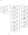
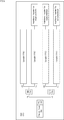
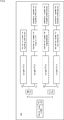
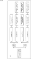
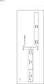
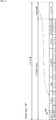
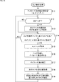
- FIG. 21 It is a flowchart explaining the example of ALP extraction processing performed by the ALP depacketizer of FIG. 21. It is a block diagram which shows the structural example of the 5th Embodiment of ALP depacketizer. It is a block diagram which shows the structural example of the 6th Embodiment of ALP depacketizer. It is a block diagram which shows the configuration example of the hardware of the computer which executes a series of processing by a program.
- FIG. 1 is a diagram showing a configuration of an embodiment of a transmission system to which the present technology is applied.
- the system is a logical collection of a plurality of devices.
- the transmission system 1 is composed of a transmission device 11 and a reception device 12.
- data transmission conforming to a digital broadcasting standard such as ATSC3.0 is performed.
- ATSC 3.0 which is one of the next-generation terrestrial broadcasting standards
- IP Internet Protocol
- UDP User Datagram Protocol
- the transmission device 11 transmits the content via the transmission line 13.
- the transmission device 11 transmits a broadcast stream including (components) such as video and audio constituting contents of a broadcast program and signaling as a broadcast wave via a transmission line 13.
- the receiving device 12 receives and outputs the content transmitted from the transmitting device 11 via the transmission line 13.
- the receiving device 12 receives the broadcast wave from the transmitting device 11 and acquires (components) such as video and audio constituting the content from the broadcast stream, and obtains video and audio of the content such as a broadcast program. To play.
- the transmission system 1 of FIG. 1 for simplification of explanation, only one receiving device 12 is shown, but a plurality of receiving devices 12 can be provided, and the transmitting device 11 transmits (simultaneously).
- the broadcast wave to be distributed can be simultaneously received by a plurality of receiving devices 12 via the transmission line 13.
- a plurality of transmission devices 11 can be provided.
- Each of the plurality of transmitters 11 transmits a broadcast wave including a broadcast stream as a separate channel, for example, in a separate frequency band, and the receiver 12 transmits a broadcast wave including a broadcast stream from each channel of the plurality of transmitters 11. , You can select the channel to receive the broadcast stream.
- the transmission line 13 in addition to terrestrial broadcasting (terrestrial broadcasting), is, for example, satellite broadcasting using a broadcasting satellite (BS: Broadcasting Satellite) or a communication satellite (CS: Communications Satellite). Alternatively, it may be a transmission line for wired broadcasting (CATV) using a cable.
- BS Broadcasting Satellite
- CS Communications Satellite
- CATV wired broadcasting
- FIG. 2 is a diagram showing a configuration example of the transmission device 11 of FIG.
- the transmission device 11 includes an AV encoder 31, FLUTE encoder 32, UDP / IP packetizer 33, ALP packetizer 34, BB packetizer 35, scrambler 36, BCH, CRC, none encoder 37, LDPC encoder 38, and bit interleaver. It is composed of 40, a data mapper 41, a time encoder 44, a frame mapper 45, a frequency encoder 46, an OFDM transmission unit 47, and an RF output unit 48.
- the AV encoder 31 encodes video and audio (components) data according to a predetermined coding method, and supplies the data to the FLUTE encoder 32.
- the FLUTE encoder 32 processes (encodes) the data from the AV encoder 31 to generate data corresponding to the FLUTE (File Delivery over Unidirectional Transport) format, and supplies the data to the UDP / IP packetizer 33.
- the UDP / IP packetizer 33 processes the data from the FLUTE encoder 32 to generate an IP packet (UDP / IP packet) including the UDP packet and supplies it to the ALP packetizer 34.
- the ALP packetizer 34 processes the UDP / IP packet from the UDP / IP packetizer 33 to generate an ALP (ATSC Link layer Protocol) packet and supplies it to the BB packetizer 35.
- ALP ATSC Link layer Protocol
- the BB packetizer 35 processes the ALP packet (second packet) from the ALP packetizer 34 to generate a BB (BaseBand) packet (first packet) and supplies it to the scrambler 36.
- the scrambler 36 scrambles the data (BB packet) from the BB packetizer 35, and supplies the resulting data to the BCH, CRC, none encoder 37.
- the BCH, CRC, none encoder 37 encodes the data from the scrambler 36 and supplies the resulting data to the LDPC encoder 38.
- the LDPC encoder 38 encodes the data from the BCH, CRC, none encoder 37 by LDPC (Low Density Parity Check), and supplies the data obtained as a result to the bit interleaver 40.
- the bit interleaver 40 performs bit interleaving on the data from the LDPC encoder 38, and supplies the data after the bit interleaving to the data mapper 41.
- the data mapper 41 maps the data from the bit interleaver 40 to a signal point representing one symbol of quadrature modulation in units of one or more sign bits (symbol units) of the data (LDPC code) and is orthogonal. Perform modulation (multi-level modulation).
- the data obtained by the processing in the data mapper 41 is supplied to the time interleaver 44.
- the time interleaver 44 performs time interleaving on the data from the data mapper 41, and supplies the data after the time interleaving to the frame mapper 45.
- the frame mapper 45 performs processing related to a frame (physical layer frame) on the data from the time interleaver 44, and supplies the data obtained as a result to the frequency interleaver 46.
- the frequency interleaver 46 performs frequency interleaving on the data from the frame mapper 45, and supplies the data after the frequency interleaving to the OFDM transmission unit 47.
- the OFDM transmission unit 47 processes the data from the frequency interleaver 46 to generate an OFDM (Orthogonal Frequency Division Multiplexing) signal and supplies it to the RF output unit 48.
- the RF output unit 48 is connected to an antenna (not shown) and transmits an OFDM signal from the OFDM transmission unit 47 as an RF (Radio Frequency) signal via the transmission line 13.
- the transmission device 11 is configured as described above.
- FIG. 3 is a diagram showing a configuration example of the receiving device 12 of FIG.
- the receiving device 12 includes an RF input unit 61, an OFDM receiving unit 62, a frequency deinterleaver 63, a frame demapper 64, a time deinterleaver 65, a data demapper 68, a bit deinterleaver 69, and an LDPC decoder 71.
- the RF input unit 61 is connected to an antenna (not shown), receives an RF signal transmitted from the transmitting device 11 via the transmission line 13, and supplies the RF signal as an OFDM signal to the OFDM receiving unit 62.
- the OFDM receiving unit 62 processes the OFDM signal from the RF input unit 61, and supplies the data obtained thereby to the frequency deinterleaver 63.
- the frequency deinterleaver 63 performs frequency deinterleave on the data from the OFDM receiving unit 62, and supplies the data after the frequency deinterleave to the frame demapper 64.
- the frame demapper 64 performs processing related to a frame (physical layer frame) on the data from the frequency deinterleaver 63, and supplies the data obtained as a result to the time deinterleaver 65.
- the time deinterleaver 65 performs time deinterleave on the data from the frame demapper 64, and supplies the data after the time deinterleave to the data demapper 68.
- the data demodulator 68 demaps the data (data on the constellation) from the time deinterleaver 65 based on the arrangement (constellation) of the signal points determined by the quadrature modulation performed on the transmission device 11 side. (Signal point arrangement decoding) is performed and quadrature demodulated, and the data (LDPC code) obtained as a result is supplied to the bit deinterleaver 69.
- the bit deinterleaver 69 performs bit deinterleave on the data from the data demapper 68, and supplies the data after the bit deinterleave to the LDPC decoder 71.
- the LDPC decoder 71 LDPC-decodes the data from the bit deinterleaver 69, and supplies the data obtained as a result to the BCH, CRC, none decoder 72.
- the BCH, CRC, none decoder 72 decodes the data from the LDPC decoder 71, and supplies the data obtained as a result to the descrambler 73.
- the descrambler 73 descrambles the data from the BCH, CRC, none decoder 72, and supplies the resulting data to the BB depacketizer 74.
- the BB depacketizer 74 extracts and processes BB packets from the data from the descrambler 73, and supplies the resulting data to the ALP depacketizer 75.
- the ALP depacketizer 75 extracts and processes ALP packets from the data from the BB depacketizer 74, and supplies the resulting data to the UDP / IP depacketizer 76.
- the UDP / IP depacketizer 76 extracts and processes UDP / IP packets from the data from the ALP depacketizer 75, and supplies the resulting data to the FLUTE decoder 77.
- the FLUTE decoder 77 processes (decodes) the data (data corresponding to the FLUTE format) from the UDP / IP depacketizer 76, and supplies the data obtained as a result to the AV decoder 78.
- the AV decoder 78 decodes the data from the FLUTE decoder 77 according to a predetermined decoding method, and outputs the video or audio (component) data obtained as a result.
- the receiving device 12 is configured as described above.
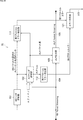
- FIG. 4 is a block diagram showing a configuration example of the first embodiment of the ALP depacketizer 75.
- the ALP depacketizer 75 (processing unit) has a BB header interpretation unit 101, an ALP header interpretation unit 102, and an ALP extraction unit 103.
- the BB header interpretation unit 101 acquires the BB packet data from the transmission line 104, and acquires the BB header data of the BB packet.
- the transmission line 104 transmits the data of the BB packet from the BB depacketizer 74 of FIG. 3 to the ALP extraction unit 103.
- FIG. 5 is a diagram showing the structure of the BB packet.
- a BB packet is composed of a BB header (BB Header) and a BB payload (BB packet payload).
- the BB header contains data such as the length of the BB packet (packet length) and the ALP start pointer (described later).
- One or more ALP packets are stored in the BB payload.
- ALP packet is composed of ALP header (ALP Header) and ALP payload (ALP payload).
- the ALP header contains data that specifies the packet type, the length of the ALP header (header length), the length of the ALP payload (payload length), and the like.
- One or more IP packets are stored as transmission data in the ALP payload.
- the BB header interpreting unit 101 acquires the BB header data from the transmission line 104
- the BB header interpreting unit 101 acquires the ALP start pointer included in the BB header.
- the ALP start pointer is data indicating the start position of the first (head) ALP header in the ALP header of the ALP packet stored in the BB packet.
- the ALP packet including the first ALP header in the BB packet (ALP packet consisting of the first ALP header and the subsequent ALP payload) is called the first ALP packet.
- the BB header interpretation unit 101 supplies the ALP start pointer to the ALP header interpretation unit 102.
- the BB header interpretation unit 101 may be a component of the BB depacketizer 74 shown in FIG.
- the ALP header interpretation unit 102 acquires the data of the ALP header of the ALP packet from the BB packet transmitted by the transmission line 104. Further, the ALP header interpreting unit 102 detects the packet length (ALP packet length) of the ALP packet based on the acquired ALP header data, and specifies the head position of the ALP packet to be transmitted next. The ALP header interpretation unit 102 has a function of correcting the data when detecting the packet length based on the data of the ALP header, which will be described in detail later.
- the ALP header interpretation unit 102 supplies the detected ALP packet length to the ALP extraction unit 103. Details of the ALP packet length detection process and the like will be described later.
- the ALP extraction unit 103 extracts the ALP packet from the BB packet transmitted by the transmission line 104 based on the ALP packet length from the ALP header interpretation unit 102, and extracts the extracted ALP packet by the transmission line 105 in UDP / Supply to IP Depacketizer 76.
- FIG. 6 is an explanatory diagram illustrating a process of extracting an ALP packet from a BB packet.
- the left and right adjacent BB packet PA and BB packet PB exemplify two BB packets that are sequentially transmitted from the BB depacketizer 74 to the ALP extraction unit 103 by the transmission line 104.
- the BB header interpretation unit 101 of FIG. 4 acquires the data of the BB header of the BB packet PA from the transmission line 104 and detects the ALP start pointer included in the BB header.
- the ALP start pointer is data that identifies the start position a-1 of the first (head) ALP header among one or more ALP headers included in the BB packet PA. Assuming that the ALP packet including the first ALP header in an arbitrary BB packet is called the head ALP packet, the ALP head pointer is data for specifying the head position of the head ALP packet.
- the start position of the ALP packet, the ALP header, or the like represents the position of the start bit of the ALP packet, the ALP header, or the like in the bit string of the BB packet.
- the BB header interpretation unit 101 supplies the detected ALP start pointer to the ALP header interpretation unit 102.
- the ALP header interpretation unit 102 identifies the start position a-1 of the start ALP packet based on the ALP start pointer.
- the ALP header interpretation unit 102 acquires the data of the ALP header of the head ALP packet in the BB packet PA from the transmission line 104 based on the ALP head pointer from the BB header interpretation unit 101.
- the ALP header interpreting unit 102 detects the header length of the ALP header and the payload length of the ALP payload (the header length and payload length of the ALP packet) based on the acquired data of the ALP header of the first ALP packet. Then, the ALP header interpretation unit 102 calculates (detects) the packet length of the head ALP packet by adding the header length and the payload length.
- the ALP header interpretation unit 102 has a function of correcting the payload length of the ALP header, which will be described in detail later.
- the ALP header interpreting unit 102 identifies the head position a-2 of the second ALP packet (the ALP packet next to the head ALP packet) in the BB packet PA based on the packet length of the detected head ALP packet.
- the start position a-2 of the second ALP packet is the position of the next bit with respect to the end position (position of the last bit) of the first ALP packet according to the packet length of the first ALP packet.
- the ALP header interpretation unit 102 supplies the packet length of the detected first ALP packet to the ALP extraction unit 103.
- the ALP extraction unit 103 sets the first ALP packet from the first position a-1 of the first ALP packet to the first position a-2 of the second ALP packet into the BB packet PA. Extract from (BB payload).
- the ALP header interpreting unit 102 specifies the start position of the start ALP packet for each BB packet based on the ALP start pointer of the BB header.
- the ALP header interpreting unit 102 specifies each of the head positions of the ALP packets included in each BB packet based on the packet length of the previous ALP packet (the next ALP based on the packet length of the ALP packet). Identify the beginning position of the packet). That is, the ALP header interpreting unit 102 specifies the end position (position of the end bit) of the previous ALP packet based on the start position and the packet length of the previous ALP packet among the two consecutive ALP packets before and after. Then, the ALP header interpreting unit 102 specifies the position of the next bit at the end position of the previous ALP packet as the start position of the subsequent ALP packet. The ALP header interpretation unit 102 detects the packet length of the previous ALP packet based on the data of the ALP header of the previous ALP packet.
- the ALP header interpretation unit 102 supplies the packet length (ALP packet length) of the ALP packet detected from the ALP header to the ALP extraction unit 103.
- the ALP extraction unit 103 transmits the head position a-2 and the head position a-3 of the second and subsequent ALP packets of the BB packet PA in FIG. 6 from the transmission line 104 based on the ALP packet length from the ALP header interpretation unit 102. It is detected by counting the timing to be performed by the self-propelled counter.
- the ALP extraction unit 103 extracts the ALP packets included in the BB packets from the BB depacketizer 74 for each ALP packet. Then, the ALP extraction unit 103 supplies the ALP packet extracted from the BB packet from the BB depacketizer 74 to the UDP / IP depacketizer 76 of FIG. 3 by the transmission line 105.
- the third ALP packet in the BB packet PA is divided into a BB packet PA and a BB packet PB.
- the data of one ALP packet is divided into a plurality of BB packets and transmitted in this way, the data of the BB header of the BB packet intervenes in the data of the one ALP packet transmitted to the ALP extraction unit 103. do.
- the ALP extraction unit 103 extracts the ALP packet data from the BB payload data excluding the BB header data, and concatenates the extracted data for the common (same) ALP packet.
- the ALP extraction unit 103 starts with the BB from the data at the head position a-3 of the third ALP packet among the data of the BB payload of the BB packet PA. Extract up to the data at the end of the packet PA.
- the ALP extraction unit 103 includes the data of the BB payload of the BB packet PB following the BB packet PA, from the data of the head position of the BB payload to the data of the bit immediately before the head position b-1 of the head ALP packet. Is extracted. Then, the ALP extraction unit 103 concatenates the data extracted from each of the BB packet PA and the BB packet PB.
- the ALP packet divided into the BB packet PA and the BB packet PB is extracted as one ALP packet.
- the ALP header interpretation unit 102 and the ALP extraction unit 103 can specify the head position of the head ALP packet in the BB packet based on the ALP packet length in the same manner as the ALP packet other than the head ALP packet. That is, if the start position of the next ALP packet specified based on the ALP packet length is within the data range of the next and subsequent BB packets, the next ALP packet is included in the next and subsequent BB packets. It is an ALP packet.
- the ALP header interpreting unit 102 sets the position of the bit next to the end position where the number of data from the beginning position of the ALP packet in the BB payload excluding the data of the BB header becomes the packet length of the ALP packet as the beginning ALP. It can be specified as the start position of the packet.
- the ALP header interpretation unit 102 and the ALP extraction unit 103 specify the head position b-1 of the head ALP packet in the BB packet PB of FIG. 6 based on the packet length of the third ALP packet in the BB packet PA.
- the ALP header interpreting unit 102 is one before the BB packet PA when the ALP packet is transmitted by the BB packet (not shown) before the BB packet PA.
- the head position a-1 of the head ALP packet can be specified based on the packet length of the ALP packet of.
- the ALP packet has a structure conforming to the terrestrial broadcasting standard ATSC3.0, and the explanation mainly focuses on the header length and payload length of the ALP packet, and the content and meaning of the data contained in the ALP packet. The description of the above will be omitted as appropriate.
- the ALP header contains data representing the packet type (Packet_Type) of the ALP packet.
- the packet type is specifically 3-bit data, and represents eight types of packet types from 000 to 111 in binary.
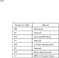
- FIG. 7 is a diagram showing the packet type value (Packet_TypeValue) of the ALP packet and the meaning (Meaning) of the packet type of each value.
- each packet type when the value of the packet type is 000 to 111 is referred to as packet type 000 to packet type 111.
- Eight types of packet types 000 to 111 are defined as packet types. Currently valid packet types are 5 types of packet types 000, packet type 010, and packet type 100, excluding 3 types of packet types 001, packet type 011 and packet type 101, which are reserved as reserved. , Packet type 110, and packet type 111.
- FIG. 8 is a diagram showing the structure of ALP headers of packet type 000 and packet type 010.
- Packet_Type is placed at the beginning of the ALP header.
- Packet_Type is data representing the packet type, and in FIG. 8, Packet_Type is set to 000 or 010.
- PC Payload_Configuration
- HM Header_Mode
- Length represents the payload length of the ALP payload.
- the payload length of the ALP payload can be in the range of 0 to 2047 bits, which can be represented by 11 bits.
- Additional header for single packets includes the data of the upper 5 bits (Length_MSB (not shown)) of the 16 bits representing the payload length of the ALP payload.
- the payload length of the ALP payload is represented by a total of 16 bits of data in which Length_MSB is the high-order bit and Length is the low-order bit, and can take a value in the range of 0 to 65535 bits.
- Additional header for single packets includes SIF (Sub-stream Identifier Flag), HEF (Header Extension Flag), etc. (not shown) in addition to Length_MSB.
- Length represents the payload length of the ALP payload.
- the payload length of the ALP payload can be in the range of 0 to 2047 bits, which can be represented by a length of 11 bits.
- Seg_SN segment_sequence_number
- LSI last_segment_indicator
- SIF Sub-stream Identifier Flag
- HEF Header Extension Flag
- the Additional header for concatenation includes the data of the upper 4 bits (Length_MSB (not shown)) of the 15 bits representing the payload length of the ALP payload.
- the payload length of the ALP payload is represented by a total of 15 bits of data in which Length_MSB is the high-order bit and Length is the low-order bit, and can take a value in the range of 0 to 32766 bits.
- Additional header for concatenation includes 3-bit Count, 1-bit SIF (Sub-stream Identifier Flag), and variable-length Component Length in addition to Length_MSB.
- the header length (number of bits) of the ALP header when the PC is 1 and the S / C is 1, is 24+ (d-1) and 12 + e.
- d is the 3-bit Count value in the Additional header for concatenation, and the Count value d is included in the ALP payload. Represents the number of IP packets.
- Component Length represents the packet length of each IP packet excluding the last IP packet among the IP packets included in the ALP payload. Since the packet length of one IP packet can take a value represented by 12 bits, ComponentLength represents (d-1) 12-bit data representing the packet length of (d-1) IP packets. Have. Therefore, (d-1) and 12 of 24+ (d-1) and 12 + e, which are the header lengths (number of bits) of the ALP header, represent the number of bits of ComponentLength.
- the e bits of the header length (number of bits) of the ALP header, 24+ (d-1) and 12 + e, are 0 bits when the Count value d is an odd number, and the Count value d is an even number. In some cases, it is 4 bits. Therefore, ⁇ 3+ (d-1) ⁇ 3/2 + e / 8 ⁇ (bytes) when 24+ (d-1) ⁇ 12 + e is divided by 8 (bits) and expressed in bytes is when d is an odd number.
- the number of bits of Additional header for concatenation obtained by the value d of Count is represented by AHb (d).
- the header length (number of bits) of the ALP header is 16 + AHb (d).
- FIG. 9 is a diagram showing the structure of the ALP header of packet type 100.
- the ALP header of packet type 100 in FIG. 9 is common to the ALP header of FIG. 8 in that it has a 3-bit packet type (Packet_Type) and a 1-bit PC in order from the beginning of the ALP header.
- Packet_Type 3-bit packet type
- PC 1-bit PC
- the ALP header of FIG. 9 has a 1-bit HM after the PC when the PC is 0, and has a 1-bit S / C after the PC when the PC is 1. Common with 8 ALP headers. Further, the ALP header of FIG. 9 is a point having an 11-bit length after HM when PC is 0 and HM is 0, and HM when PC is 0 and HM is 1. It has 11 bits of Length and 8 bits of Additional header for long packets (Additional header for single packets). If the PC is 1 and the S / C is 0, 11 bits after the S / C. Length and 8-bit Additional header for segmentation, 11-bit Length and AHb (d) -bit Additional header for category when the PC is 1 and the S / C is 1. In that it has, it is common with the ALP header of FIG.
- the ALP header in FIG. 9 has a new additional header for Signaling Information after Length when HM is 0, and Additional header for Signaling after Additional header for long packets when HM is 1.
- a point that newly has Information a point that newly has Additional header for Signaling Information after Additional header for segmentation when S / C is 0, and an Additional header for categorynation when S / C is 1. It differs from the ALP header in FIG. 8 in that it newly has Additional header for Signaling Information after.
- the HM of an arbitrary value and the Additional header for Signaling Information in the S / C of an arbitrary value are 40-bit (5 bytes) data.
- Additional header for Signaling Information includes signaling_type, signaling_type_extension, signaling_version, signaling_format, and signaling_encoding (not shown).
- the payload length of the ALP payload is the same as when PC is 0 and HM is 0 in FIG. 8, and can be represented by a length of 11 bits. It can take a value in the range of 2047 bits.
- the payload length of the ALP payload is the same as when the PC is 0 and the HM is 1 in FIG. 8, which is 5 (not shown) in the Additional header for long packets. It is represented by a total of 16 bits of data in which the Length_MSB of the bit is the high-order bit and the Length is the low-order bit. Therefore, the payload length of the ALP payload can be in the range of 0 to 65535 bits.
- the payload length of the ALP payload is the same as when the PC is 1 and the S / C is 0 in FIG. 8, and is represented by a length of 11 bits. It can take a value in the range of 0 to 2047 bits that can be.
- the header length of the ALP header is 24 bits, which is the sum of the bit numbers of the 3-bit packet type (Packet_Type), 1-bit PC, 1-bit HM, 11-bit Length, and 8-bit Additional header for segmentation. It is 64 bits (8 bytes) obtained by adding 40 bits (5 bytes), which is the number of bits of Additional header for Signaling Information (3 bytes).
- the payload length of the ALP payload is the same as when the PC is 1 and the S / C is 1 in FIG. It is represented by a total of 15 bits of data in which the 4-bit Length_MSB shown in the figure is the upper bit and the Length is the lower bit, and can take a value in the range of 0 to 32766 bits.
- the header length of the ALP header is the sum of the number of bits of the 3-bit packet type (Packet_Type), 1-bit PC, 1-bit HM, 11-bit Length, and AHb (d) bits Additional header for concatenation. It is 56 bits (7 bytes) + AHb (d) bits obtained by adding 16 bits (2 bytes) + AHb (d) bits and 40 bits (5 bytes) which is the number of bits of header for Signaling Information.
- AHb (d) is the number of bits of the Additional header for concatenation described in the ALP header of FIG. 8, and is obtained from the value d of the Count data included in the Additional header for concatenation.
- FIG. 10 is a diagram showing the structure of the ALP header of the packet type 110.
- the ALP header of the packet type 110 in FIG. 10 is common to the ALP header of FIG. 8 in that it has a 3-bit packet type (Packet_Type) and a 1-bit PC in order from the beginning of the ALP header.
- Packet_Type 3-bit packet type
- PC 1-bit PC
- the ALP header of FIG. 10 has a 1-bit HM after the PC when the PC is 0, and has a 1-bit S / C after the PC when the PC is 1. Common with 8 ALP headers. Further, the ALP header of FIG. 10 is a point having an 11-bit length after HM when PC is 0 and HM is 0, and HM when PC is 0 and HM is 1. It has 11 bits of Length and 8 bits of Additional header for long packets (Additional header for single packets). If the PC is 1 and the S / C is 0, 11 bits after the S / C. Length and 8-bit Additional header for segmentation, 11-bit Length and AHb (d) -bit Additional header for category when the PC is 1 and the S / C is 1. It is common to the ALP header of FIG. 8 in that it has.
- the ALP header in FIG. 10 has a new additional header for Type Extension after Length when HM is 0, and Additional header for Type after Additional header for single packets when HM is 1.
- a point that has a new Extensin a point that has a new Additional header for Type Extensin after the Additional header for segmentation when the S / C is 0, and an Additional header for categorynation when the S / C is 1. It differs from the ALP header in FIG. 8 in that it has a new Additional header for Type Extension after.
- the HM of an arbitrary value and the Additional header for Type Extension in the S / C of an arbitrary value are 16-bit (2 bytes) data.
- Additional header for Type Extension includes extended_type (not shown).
- the payload length of the ALP payload is the same as when PC is 0 and HM is 0 in FIG. 8, and can be represented by a length of 11 bits. It can take a value in the range of 2047 bits.
- the payload length of the ALP payload is the same as when the PC is 0 and the HM is 1 in FIG. 8, which is 5 (not shown) in the Additional header for long packets. It is represented by a total of 16 bits of data in which the Length_MSB of the bit is the high-order bit and the Length is the low-order bit. Therefore, the payload length of the ALP payload can take a value in the range of 0 to 65535 bits.
- the payload length of the ALP payload is the same as when the PC is 1 and the S / C is 0 in FIG. 8, and is represented by a length of 11 bits. It can take a value in the range of 0 to 2047 bits that can be.
- the header length of the ALP header is 24 bits, which is the sum of the number of bits of the 3-bit packet type (Packet_Type), 1-bit PC, 1-bit HM, 11-bit Length, and 8-bit Additional header for segmentation. It is 40 bits (5 bytes) obtained by adding 16 bits (2 bytes), which is the number of bits of Additional header for Type Extension (3 bytes).
- the payload length of the ALP payload is the same as when the PC is 1 and the S / C is 1 in FIG. It is represented by a total of 15 bits of data in which the 4-bit Length_MSB shown in the figure is the high-order bit and the Length is the low-order bit. Therefore, the payload length of the ALP payload can be in the range of 0 to 32766 bits.
- the header length of the ALP header is the sum of the number of bits of the 3-bit packet type (Packet_Type), 1-bit PC, 1-bit HM, 11-bit Length, and AHb (d) bits Additional header for concatenation. It is 32 bits (4 bytes) + AHb (d) bits obtained by adding 16 bits (2 bytes) + AHb (d) bits and 16 bits (2 bytes) which is the number of bits of Additional header for Type Extension.
- AHb (d) is the number of bits of the Additional header for concatenation described in the ALP header of FIG. 8, and is obtained from the value d of the Count data included in the Additional header for concatenation.
- FIG. 11 is a diagram showing the structure of the ALP header of packet type 111.
- Packet_Type indicating the packet type is arranged at the beginning of the ALP header.
- Packet_Type is set to 111.
- NUMTS Number of TS packets
- AHF Additional Header Flag
- AHF is the data at the end of the ALP header.
- HDM Header Deletion Mode
- DNP Deleted Null Packets
- the payload length of the ALP payload is obtained based on the value of NUMTS in consideration of the packet length of the TS packet etc. stored in the ALP payload.
- FIG. 12 is a diagram illustrating a specific structure of an ALP packet of packet type 000.
- the ALP packet is packet type 000.
- the 11th bit consisting of the 6th and 16th bits from the beginning of the ALP packet (ALP header) and the bits between them is the Length of the ALP header.
- the value indicated by Length represents the payload length of the ALP payload (described as "payload” in the figure). For ALP packets of packet type 000, Length is followed by the ALP payload.
- the header length of the ALP header is 16 bits (2 bytes), which is the sum of the bit numbers of the packet type, PC, HM, and Length.
- the payload length of the ALP payload is the value of the Length of the ALP header and can be in the range of 0 to 2047 bits.
- the packet length of the ALP packet is a value obtained by adding the ALP header, the header length, and the payload length of the ALP payload.
- FIG. 13 is a diagram illustrating a specific structure of an ALP packet of packet type 100.
- the ALP packet is packet type 100.
- the 11th bit consisting of the 6th and 16th bits from the beginning of the ALP packet (ALP header) and the bits between them is the Length of the ALP header.
- the value of Length represents the payload length of the ALP payload (denoted as "payload" in the figure).
- the additional header for Signaling Information is 8-bit (1 byte) signaling_type (described as “type” in the figure), 16-bit (2 bytes) signaling_type_extension (described as “extension” in the figure), and 8-bit (described as “extension” in the figure).
- 1-byte signaling_version (described as "version” in the figure)
- 2-bit signaling_format (described as “fmt” in the figure)
- 2-bit signaling_encoding described as “enc” in the figure
- 4-bit Reserved include.
- the ALP payload follows the Additional header for Signaling Information.
- the header length of the ALP header is 56 bits (7 bytes), which is the sum of the number of bits of the packet type, PC, HM, Length, and Additional header for Signaling Information. be.
- the payload length of the ALP payload is the value of the Length of the ALP header and can be in the range of 0 to 2047 bits.
- the packet length of the ALP packet is a value obtained by adding the ALP header, the header length of 56 bits (7 bytes), and the payload length of the ALP payload.
- the header length of the ALP header and the payload length of the ALP payload in the ALP packet can be detected based on the data of the ALP header for any packet type ALP packet as described with reference to FIGS. 8 to 11. ..
- ALP regardless of the packet type. It is detected by a common method according to the value in the header PC, HM, and S / C.
- the payload length is the 11-bit Length value of the ALP header (range 0 to 2047 bits). Value in).
- the payload length is indicated by 16-bit data in which the 5-bit Length_MSB of the ALP header is the high-order bit and the 11-bit Length of the ALP header is the low-order bit.
- a value (a value in the range of 0 to 65535).
- the payload length is 16-bit data in which the 5-bit Length_MSB of the ALP header is the high-order bit and the 11-bit Length of the ALP header is the low-order bit. Is a value (a value in the range of 0 to 32766) indicated by.
- the payload length of ALP paid is detected based on the value of NUMTS in the ALP header.
- the data concatenated with the Length_MSB in the ALP header as the high-order bit and the Length of the ALP header as the low-order bit is called the extended Length.
- the ATSC3.0 standard stipulates that the payload length of the ALP payload is set in the Length or extended Length in the ALP header.
- the ATSC3.0 standard stipulates that the value calculated based on the NUMTS value and a predetermined calculation formula is the payload length of the ALP payload.
- the payload length of the ALP payload is set to Length or extended Length due to the difference in interpretation of the ALP header in the country where the transmitting device 11 is manufactured or used.
- a value different from the above value is set, or an ALP pecket different from the payload length calculated by the NUMTS value and the predetermined calculation formula may be generated. That is, in the receiving device 12 of FIG. 1, the payload length detected from the data of the ALP header according to the standard may be different from the true payload length as described above.
- FIG. 14 is a diagram illustrating a case where the value of Length of the ALP header in the ALP packet of packet type 100 of FIG. 13 is different from the payload length of the ALP payload.
- the ALP packet of FIG. 14 illustrates a case where the PC of the ALP header is 0 and the ALP header is HM0 in the ALP packet of the packet type 100.
- the Length of the ALP header in the ALP packet of FIG. 14 is the ALP payload (ALP packet) from the position of the bit next to the Length, that is, the beginning position of the signaling_type (described as “type” in the figure). The number of bits up to the end position of is set.
- the value of Length is larger than the true payload length (number of bits) of the ALP payload by the amount including the number of bits of some data (Additional header for Signaling Information in FIG. 9) of the ALP header. That is, the true payload length of the ALP payload is the number of bits obtained by subtracting 40 bits (5 bytes), which is the number of bits of Additional header for Signaling Information, from the value of Length.
- the receiving device 12 detects the value of the Length of the ALP header as the payload length of the ALP payload for the ALP packet of FIG. 14 according to the standard as in FIG. 13, the detected payload length is 40 more than the actual one. It increases by a bit (5 bytes), and the packet length also increases by 40 bits (5 bytes).
- FIG. 15 is a diagram illustrating a problem that occurs when the value of Length of the ALP header is different from the payload length of the ALP payload (in the case of FIG. 14).
- the BB packet PA and BB packet PB of FIG. 15 are the same as the BB packet PA and BB packet PB of FIG. 6 except that the value of Length of the ALP header is different from the payload length of the ALP payload.
- the BB header interpreting unit 101 correctly identifies the head position a-1 of the head ALP header based on the ALP head pointer of the BB header in the BB packet PA of FIG.
- the ALP header interpreting unit 102 correctly identifies the head position a-1 of the head ALP header by the ALP head pointer from the BB header interpreting unit 101.
- the ALP header interpretation unit 102 acquires the data of the ALP header in the head ALP packet of the BB packet PA from the transmission line 104 based on the head position a-1 of the head ALP header specified by the ALP head pointer from the BB header interpretation unit 101. do.
- the ALP header interpreting unit 102 detects the header length of the ALP header and the payload length of the ALP payload in the head ALP packet based on the acquired ALP header data, adds the header length and the payload length, and adds the head ALP. Detect the packet length of the packet.
- the payload length of the ALP payload detected by the ALP header interpreting unit 102 based on the data of the ALP header as specified is different from the true payload length. Therefore, the packet length detected by the ALP header interpreting unit 102 is also different from the true packet length.
- the head position a'-2 of the second ALP packet specified by the ALP header interpreting unit 102 based on the packet length of the head ALP packet is incorrect and is different from the true head position a-2.
- the head position a'-2 shifts backward (in time) from the true head position a-2.
- the ALP header interpretation unit 102 supplies the ALP packet length corresponding to the head position a'-2 to the ALP extraction unit 103, the ALP extraction unit 103 cannot specify the correct head position a-2 of the second ALP packet. ..
- the ALP header interpreting unit 102 acquires the data of the ALP header in the ALP packet on the second surface at the specified head position a'-2, and the third ALP is based on the packet length of the second ALP packet. Identify the beginning position a'-3 of the packet.
- the ALP header Interpretation unit 102 cannot correctly identify the head position a-3 of the third ALP packet.
- the ALP header interpreting unit 102 cannot acquire the ALP header data in the second ALP packet from the correct position, the ALP header Length data cannot be acquired from the actual Length position. Therefore, the payload length detected by the ALP header interpretation unit 102 becomes an unpredictable value, and the start position a'-3 of the third ALP packet specified by the ALP header interpretation unit 102 is incorrect, and the true start position a'is set. It's different.
- the ALP header interpreting unit 102 uses the ALP head pointer from the BB header interpreting unit 101 to correct the head ALP packet. Unless the start position is specified, the correct start position cannot be specified based on the packet length.
- the BB header interpreting unit 101 sets the head ALP packet in the BB packet PA and the BB packet PB based on the ALP head pointer of the BB header. Correctly identify the head position a-1 and the head position b-1.
- the head positions a'-2, a'-3, b'-2, and b'-3 of the ALP packet specified by the ALP header interpreting unit 102 based on the packet length of the ALP packet are the true head positions a. It is different from -2, a-3, b-2, and b-3. Even when the head position b'-1 of the head ALP packet in the BB packet PB is specified based on the packet length of the third ALP packet in the BB packet PA, the head position b'-1 is the true head position b. Different from -1.
- the ALP header interpreting unit 102 supplies the ALP packet length corresponding to a position different from the true starting position of the ALP packet to the ALP extraction unit 103 except at the beginning position of the beginning ALP packet, so that the ALP extraction unit 103 , The head position of the ALP packet in the BB packet cannot be correctly specified, and the ALP packet cannot be extracted appropriately.
- a defect is illustrated by taking as an example a case where the value of the Length data of the ALP header is detected as the payload length of the ALP payload as a form in which the payload length detected based on the data of the ALP header is different from the true payload length. did. Similar problems occur when the value of the extended Length of the ALP header is detected as the payload length of the ALP payload, and the value of the NUMTS data and the value calculated by a predetermined formula are detected as the payload length of the ALP payload. It also happens in some cases.
- the ALP header interpretation unit 102 of FIG. 4 adds (subtracts) a correction value of a value that can be changed to the detected payload length among the header length of the ALP header detected based on the data of the ALP header and the payload length of the ALP payload. In the case of, a negative correction value is added) to programmatically correct the payload length.
- the ALP header interpreting unit 102 performs ALP for each of the packet types 000 to 111 of the ALP packet, which are effectively used packet type 000, packet type 010, packet type 100, packet type 110, and packet type 111. Set the correction value to be added to the detected packet length based on the header data. Further, the ALP header interpretation unit 102 sets the correction value for each packet type to a value specified based on, for example, a user operation from an operation unit (not shown).
- the correction value for the ALP packet of packet type 000 is the correction variable ⁇
- the correction value for the ALP packet of packet type 010 is the correction variable ⁇
- the correction value for the ALP packet of packet type 100 is the correction variable ⁇
- the correction value for the packet type 110 is represented by the correction variable ⁇
- the correction value for the packet type 111 is represented by the correction variable ⁇ .
- the ALP header interpretation unit 102 uses the packet type data included in the acquired ALP header data to determine the ALP packet. Detects the packet type of. Then, the ALP header interpretation unit 102 detects the header length of the ALP header by referring to the necessary data from the data of the ALP header according to the detected packet type.
- the ALP header interpreting unit 102 describes the ALP packets of packet type 000, packet type 010, packet type 100, and packet type 110 with reference to FIGS. 8 to 10.
- packet type Packet_Type
- the ALP header interpreting unit 102 refers to the AHF value of the ALP header in addition to the packet type as described with reference to FIG. 11 for the ALP packet of the packet type 111.
- the ALP header interpreting unit 102 detects the payload length of the ALP payload by referring to the necessary data from the ALP header data according to the detected packet type. As described above, the ALP header interpreting unit 102 indicates the length of the ALP header or the length of the ALP header for ALP packets other than the packet types 111 among the packet types 000, 010, 100, 110, and 111 that are effectively used. , Detects the value of extended Length (Length and Length_MSB) as the payload length. Further, the ALP header interpreting unit 102 detects (calculates) the payload length of the ALP packet of the packet type 111 based on the value of NUMTS and a predetermined calculation formula.
- the ALP header interpreting unit 102 adds correction variables ⁇ , ⁇ , ⁇ , ⁇ , and ⁇ of values according to the packet type to the payload length of the ALP payload detected based on the data of the ALP header as correction values. , Correct the payload length.
- the values of the correction variables ⁇ , ⁇ , ⁇ , ⁇ , and ⁇ will be described later.
- the corrected payload length can be matched with the true payload length.
- the ALP header interpreting unit 102 adds the header length of the ALP header detected based on the data of the ALP header and the corrected payload length to detect (calculate) the packet length of the ALP packet, and detects (calculates) the packet length of the next ALP. Identify the beginning position of the packet. Further, the ALP header interpretation unit 102 supplies the detected ALP packet length to the ALP extraction unit 103.
- the ALP header interpretation unit 102 determines the values of the correction variables ⁇ , ⁇ , ⁇ , ⁇ , and ⁇ based on, for example, a user operation of an operation unit (not shown).
- the settable values of the correction variables ⁇ , ⁇ , ⁇ , ⁇ , and ⁇ may be arbitrary values, or may be limited to one or a plurality of predetermined values. Further, depending on the packet type, the correction variable may be fixed to a predetermined value.
- the ALP header interpreting unit 102 does not correct the payload length for the ALP packet of that packet type. In the case of an ALP packet generated according to the standard, no correction is required, so that the correction variables ⁇ , ⁇ , ⁇ , ⁇ , and ⁇ are all set to 0 as standard.
- the ALP header interpreting unit 102 uses a correction pattern ( ⁇ , ⁇ , ⁇ , ⁇ , ⁇ ) that combines the values of the correction variables ⁇ , ⁇ , ⁇ , ⁇ , and ⁇ to correct the correction variables ⁇ , ⁇ , ⁇ , and ⁇ . , ⁇ may be set at once.
- the ALP header interpreting unit 102 stores a plurality of correction patterns ( ⁇ , ⁇ , ⁇ , ⁇ , ⁇ ) having predetermined values. Then, the ALP header interpretation unit 102 sets the value of any of the plurality of stored correction patterns as the correction variables ⁇ , ⁇ , ⁇ , for example, based on the user operation of the operation unit (not shown). Set as the values of ⁇ and ⁇ .
- the appropriate values of the correction variables ⁇ , ⁇ , ⁇ , and ⁇ for the ALP packets of the packet type 000, the packet type 010, the packet type 100, and the packet type 110 are set by the transmission device 11 in FIG. 1 as the ALP header. It can be determined by the difference between the value set as the Length or the extended Length (Length and Length_MSB) of ALP packet and the true payload length of the ALP packet.
- the appropriate value of the correction variable ⁇ for the ALP packet of the packet type 111 is predetermined as the true payload length of the ALP payload in the ALP packet of the packet type 111 generated by the transmission device 11 of FIG. 1 and the value of the NUMTS. It can be determined by the difference value from the payload length calculated based on the calculation formula.
- the payload length of the ALP payload detected by the ALP header interpreter 102 based on the data of the ALP header for the ALP packets of packet type 000, packet type 010, packet type 100, packet type 110, and packet type 111. And the difference from the true payload length can be the appropriate value for the correction variable.
- the value of the correction variable is a positive value, and detection is performed based on the data in the ALP header.
- the value of the correction variable is negative if the payload length of the ALP payload is greater than the true payload length.
- the payload length of the ALP payload detected by the ALP header interpreter 102 based on the data of the ALP header is the true payload for the ALP packet of packet type 100.
- the value is 40 bits (5 bytes) larger than the length.
- the appropriate value of the correction variable ⁇ for the packet type 100 ALP packet is -40 bits (-5 bytes).
- FIGS. 14 and 15 are based on an actual case, and according to the case, the ALP header interpreting unit 102 is based on the data of the ALP header for the ALP packet of the packet type other than the packet type 100.
- the payload length of the ALP packet detected in the above matches the true payload length. Therefore, the appropriate values of the correction variables ⁇ , ⁇ , ⁇ , and ⁇ other than the correction variable ⁇ are 0.
- the ALP header interpreting unit 102 limits the values that can be set for each of the correction variables ⁇ , ⁇ , ⁇ , ⁇ , and ⁇ to one or a plurality of predetermined values.
- 0 is included as a set value that can be set for each of the correction variables ⁇ , ⁇ , ⁇ , and ⁇
- 0 and -40 bits (-5 bytes) are included as a value that can be set for the correction variable ⁇ .
- the ALP header interpreting unit 102 sets the respective values of the correction variables ⁇ , ⁇ , ⁇ , ⁇ , and ⁇ to one of the predetermined correction patterns ( ⁇ , ⁇ , ⁇ , ⁇ , ⁇ ). In the case of the embodiment, the ALP header interpreting unit 102 sets the correction pattern (0, 0, 0, 0, 0) and the correction pattern (0, 0, -40 bits (-5 bytes), 0) as the correction patterns that can be set. , 0) and.
- the appropriate values of the correction variables ⁇ , ⁇ , ⁇ , ⁇ , and ⁇ are limited to some extent depending on the model and mode of the transmitting device 11, the country in which the transmitting device 11 and the receiving device 12 are used, and the like. Therefore, rather than individually specifying and setting the values of the correction variables ⁇ , ⁇ , ⁇ , ⁇ , and ⁇ by the operation of the operation unit, a plurality of predetermined correction patterns ( ⁇ , ⁇ , ⁇ , ⁇ ) are used. , ⁇ ), it is less burdensome for the user to select an appropriate correction pattern and set it as the value of the correction variables ⁇ , ⁇ , ⁇ , ⁇ , and ⁇ .
- the model and mode of the transmitting device 11, the country in which the transmitting device 11 and the receiving device 12 are used, and the like are specified by the user by operating the operation unit, so that the values of the correction variables ⁇ , ⁇ , ⁇ , ⁇ , and ⁇ are appropriate.
- a value correction pattern may be applied.
- the receiving device 12 acquires information on the model and mode of the transmitting device 11 and automatically applies a correction pattern having appropriate values as the values of the correction variables ⁇ , ⁇ , ⁇ , ⁇ , and ⁇ . good.
- the payload length of the ALP payload detected based on the data of the ALP header in the ALP packet stored in the BB packet can be corrected, and thus conforms to the standard. Even if the ALP header is different from the interpretation, the ALP packet can be appropriately extracted from the BB packet.
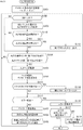
- FIG. 16 is a flowchart illustrating an example of ALP extraction processing performed by the ALP depacketizer 75 of FIG.
- step S11 the ALP header interpreting unit 102 sets a correction value for the payload length of the ALP payload. That is, the ALP header interpreting unit 102 includes correction variables ⁇ , ⁇ , ⁇ , ⁇ , and ⁇ , which are correction values for each of the packet type 000, packet type 010, packet type 100, packet type 110, and packet type 111 of the ALP packet. As the value of, for example, a predetermined value is set based on the user operation of the operation unit. The process proceeds from step S11 to step S12.
- step S12 the BB header interpreting unit 101 determines whether or not the BB header data is newly acquired from the BB packet transmitted from the BB depacketizer 74 in FIG. 3 to the ALP extraction unit 103 through the transmission line 104.
- step S12 If it is determined in step S12 that the BB header data has not been newly acquired, the process skips step S13 and proceeds to step S14.
- step S12 determines whether the BB header data has been newly acquired. If it is determined in step S12 that the BB header data has been newly acquired, the process proceeds from step S12 to step S13.
- step S13 the BB header interpretation unit 101 acquires the ALP start pointer from the newly acquired BB header data, and supplies the ALP start pointer to the ALP header interpretation unit 102.
- the process proceeds from step S13 to step S14.
- step S14 the ALP header interpreting unit 102 starts the ALP packet in which the data transmitted from the BB depacketizer 74 in FIG. 3 to the ALP extraction unit 103 is identified by the ALP head pointer from the BB header interpreting unit 101. It is determined whether or not it is the start position of the ALP packet specified by the position or the ALP packet length.
- step S14 If it is determined in step S14 that it is not the start position of the ALP packet, the process returns from step S14 to step S12.
- step S14 determines whether it is the head position of the ALP packet. If it is determined in step S14 that it is the head position of the ALP packet, the process proceeds from step S14 to step S15.
- step S15 the ALP header interpreting unit 102 acquires the data of the ALP header from the transmission line 104. At this time, the ALP header interpreting unit 102 detects the packet type of the ALP packet from the data of the ALP header. The process proceeds from step S15 to step S16.
- step S16 the ALP header interpretation unit 102 interprets the header based on the ALP header data acquired in step S15, and detects the header length and payload length of the ALP packet. The process proceeds from step S16 to step S17.
- step S17 the ALP header interpreting unit 102 corrects the payload length detected in step S16. That is, the ALP header interpreting unit 102 detects in step S16 using the value of the correction variable corresponding to the packet type of the ALP packet among the correction variables ⁇ , ⁇ , ⁇ , ⁇ , and ⁇ for which the value is set in step S11 as the correction value. Add to the payload length. The process proceeds from step S17 to step S18.
- step S18 the ALP header interpreting unit 102 calculates the packet length by adding the header length detected in step S16 and the payload length corrected in step S17, and starts the next ALP packet based on the calculated packet length. Identify the location. Further, the ALP header interpretation unit 102 supplies the calculated ALP packet length to the ALP extraction unit 103. The process proceeds from step S18 to step S19.
- step S19 the ALP extraction unit 103 identifies the head position of the next ALP packet based on the ALP packet length acquired from the ALP header interpretation unit 102 in step S18. Also, the ALP packet is extracted from the BB packet based on the start position of the previous and current ALP packets.
- the ALP extraction unit 103 supplies the ALP packet extracted from the BB packet to the UDP / IP depacketizer 76 (see FIG. 3) through the transmission line 105.
- the process returns from step S19 to step S12, and repeats from step S12.
- the payload length of the ALP payload detected based on the data of the ALP header in the ALP packet stored in the BB packet can be corrected.
- ALP packets can be appropriately extracted from BB packets even if the ALP header is different from the standard-compliant interpretation.
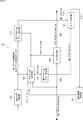
- FIG. 17 is a block diagram showing a configuration example of a second embodiment of the ALP depacketizer 75.
- the ALP depacketizer 75 of FIG. 17 has a BB header interpretation unit 101, an ALP header interpretation unit 102, an ALP extraction unit 103, a transmission line 104, a transmission line 105, a first protocol error detection unit 111, and a second protocol error detection unit 112. Has. Therefore, the ALP depacketizer 75 of FIG. 17 is common to the case of FIG. 4 in that it has a BB header interpretation unit 101, an ALP header interpretation unit 102, an ALP extraction unit 103, a transmission line 104, and a transmission line 105. However, the ALP depacketizer 75 of FIG. 17 is different from the case of FIG. 4 in that the first protocol error detection unit 111 and the second protocol error detection unit 112 are newly provided.
- the first protocol error detection unit 111 acquires the ALP start pointer output by the BB header interpretation unit 101 (supplied to the ALP header interpretation unit 102).
- the first protocol error detection unit 111 acquires the ALP packet length output by the ALP header interpretation unit 102 (supplied to the ALP extraction unit 103).
- the first protocol error detection unit 111 includes the head position of the head ALP packet based on the ALP head pointer acquired from the BB header interpretation unit 101 corresponding to the head position of the head ALP packet in each BB packet, and the head position of the head ALP packet from the ALP header interpretation unit 102.
- the first protocol error is detected based on the difference from the head position of the head ALP packet based on the acquired ALP packet length.
- the first protocol error detection unit 111 determines the start position of the start ALP packet based on the ALP start pointer from the BB header interpretation unit 101 and the start ALP packet based on the ALP packet length from the ALP header interpretation unit 102. Detect the difference from the start position.
- the first protocol error detection unit 111 determines that the first protocol error has occurred when the detected difference is equal to or greater than a predetermined threshold value, and when the detected difference is less than the predetermined threshold value, determines that the first protocol error has occurred. It is determined that the first protocol error has not occurred. As a result, the first protocol error detection unit 111 detects the first protocol error (whether or not the first protocol error has occurred).
- the first protocol error detection unit 111 When the first protocol error detection unit 111 detects the first protocol error, the first protocol error detection unit 111 outputs the first protocol error signal to an error processing unit (not shown).
- the processing for an error performed by the error processing unit by detecting the first protocol error signal is not limited to a specific processing.
- the second protocol error detection unit 112 acquires the packet type of the ALP packet detected by the ALP header interpretation unit 102 from the data of the ALP header corresponding to the head position of each ALP packet, and the second protocol error is based on the packet type. Is detected.
- the packet type of the ALP packet detected by the ALP header interpretation unit 102 is the reserved packet type 001, packet type 011 or packet type 110 shown in FIG. 7, that is, If the packet type is not effectively used, it is determined that a second protocol error has occurred, and the packet type 000, packet type 010, packet type 100, packet type 110, or other than the spare packet type is determined. , If the packet type is 111, it is determined that the second protocol error has not occurred. As a result, the second protocol error detection unit 112 detects the second protocol error (presence or absence of the second protocol error).
- the second protocol error detection unit 112 When the second protocol error detection unit 112 detects the second protocol error, the second protocol error detection unit 112 outputs a second protocol error signal to an error processing unit (not shown).
- the processing for an error performed by the error processing unit by detecting the second protocol error signal is not limited to a specific processing.
- an output unit notifies the user that an error has occurred, and a correction variable.
- the process may be a process of prompting the user to change the values of ⁇ , ⁇ , ⁇ , ⁇ , and ⁇ , a process of stopping the ALP packet extraction process by the ALP extraction unit 103, and the like.
- the payload length of the ALP header detected based on the data of the ALP header in the ALP packet stored in the BB packet can be corrected, so that the interpretation conforms to the standard.
- ALP packets can be appropriately extracted from BB packets even if they have different ALP headers.
- the ALP header interpretation unit 102 inputs the data of the ALP header. It may not be possible to obtain it correctly. For example, when the ALP header interpreting unit 102 detects a packet type from data at an erroneous position that is not an ALP header, a packet type that is not effectively used may be detected. In this case, since the second protocol error is detected by the second protocol error detection unit 112, it can be detected that the ALP header interpretation unit 102 has not correctly acquired the data of the ALP header. Therefore, it is possible to detect whether or not the values of the correction variables ⁇ , ⁇ , ⁇ , ⁇ , and ⁇ are appropriate.
- the ALP header interpretation unit 102 does not correctly acquire the ALP header data, when the ALP header interpretation unit 102 detects the packet type from the data at the wrong position that is not the ALP header, the valid packet type is May be detected. In this case, since the second protocol error detection unit 112 does not detect the second protocol error, the ALP header interpretation unit 102 does not correctly acquire the ALP header data in response to the occurrence (detection) of the second protocol error. It is difficult to detect that.
- the ALP head pointer output from the BB header interpretation unit 101 and the ALP packet length output from the ALP header interpretation unit 102 corresponding to the head position of the head ALP packet are changed. If they do not match, the first protocol error detection unit 111 detects the first protocol error. As a result, it is possible to detect that the ALP header interpreting unit 102 has not correctly acquired the ALP header data in response to the occurrence (detection) of the first protocol error. Therefore, it is possible to detect whether or not the values of the correction variables ⁇ , ⁇ , ⁇ , ⁇ , and ⁇ are appropriate.
- the first protocol error detection unit 111 and the second protocol error detection unit 112 are provided, and the first protocol error and the second protocol error can be detected. Only one of them may be detected. Even in this case, it is possible to detect whether or not the values of the correction variables ⁇ , ⁇ , ⁇ , ⁇ , and ⁇ are appropriate.
- FIG. 18 is a flowchart illustrating an example of ALP extraction processing performed by the ALP depacketizer 75 of FIG.
- steps S41 to S49 of FIG. 18 is the same as the processing of steps S11 to S19 of FIG. 16, and thus the description thereof will be omitted.
- step S43 the ALP start pointer output from the BB header interpretation unit 101 is supplied to the ALP header interpretation unit 102 and the first protocol error detection unit 111, and in step S18, the ALP header interpretation unit 102. It differs from step S13 and step S18 of FIG. 16 in that the ALP packet length output from is supplied to the ALP extraction unit 103 and the first protocol error detection unit 111.
- step S50 the first protocol error detection unit 111 determines whether or not the start position of the start ALP packet based on the ALP packet length from the ALP header interpretation unit 102 has been acquired.
- step S50 If it is determined in step S50 that the head position of the head ALP packet based on the ALP packet length has not been acquired, the process skips steps S51 and S52 and proceeds to step S44.
- step S50 If it is determined in step S50 that the head position of the head ALP packet based on the ALP packet length has been acquired, the process proceeds from step S50 to step S51.
- step S51 the first protocol error detection unit 111 determines the start position of the start ALP packet based on the ALP start pointer acquired from the BB header interpretation unit 101 and the start ALP packet based on the ALP packet length acquired from the ALP header interpretation unit 102. It is determined whether or not the head position of is different (the difference is equal to or greater than a predetermined threshold value).
- step S51 when the difference between the start position of the start ALP packet based on the ALP start pointer and the start position of the start ALP packet based on the ALP packet length is less than a predetermined threshold value, the first protocol error detection unit 111 , Step S52 is skipped and the process proceeds to step S44.
- step S51 if the difference between the head position of the head ALP packet based on the ALP head pointer and the head position of the head ALP packet based on the ALP packet length is equal to or greater than a predetermined threshold value, the process proceeds to step S52, and the process proceeds to step S52.
- the 1-protocol error detection unit 111 supplies a first protocol error signal indicating that a first protocol error has occurred to an error processing unit (not shown). The process proceeds from step S52 to step S44.
- step S53 the second protocol error detection unit 112 determines whether or not the packet type of the ALP packet obtained by the ALP header interpretation unit 102 by header interpretation in step S46 is not valid.
- step S53 If it is determined in step S53 that the packet type is valid, the process skips step S54 and proceeds to step S47.
- step S53 If it is determined in step S53 that the packet type is not valid, the process proceeds from step S53 to step S54.
- step S54 the second protocol error detection unit 112 supplies a second protocol error signal indicating that a second protocol error has occurred to an error processing unit (not shown). The process proceeds from step S54 to step S47.
- the payload length of the ALP payload detected based on the data of the ALP header in the ALP packet stored in the BB packet can be corrected.
- ALP packets can be appropriately extracted from BB packets even if the ALP header is different from the standard-compliant interpretation.
- FIG. 19 is a block diagram showing a configuration example of a third embodiment of the ALP depacketizer 75.
- the ALP depacketizer 75 of FIG. 19 includes a BB header interpretation unit 101, an ALP header interpretation unit 102, an ALP extraction unit 103, a transmission line 104, a transmission line 105, a first protocol error detection unit 111, a second protocol error detection unit 112, and , Has an error determination unit 121. Therefore, the ALP depacketizer 75 of FIG. 19 has a BB header interpretation unit 101, an ALP header interpretation unit 102, an ALP extraction unit 103, a transmission line 104, a transmission line 105, a first protocol error detection unit 111, and a second protocol error detection. It is common to the case of FIG. 17 in that it has a portion 112. However, the ALP depacketizer 75 of FIG. 19 is different from the case of FIG. 17 in that an error determination unit 121 is newly provided.
- the error determination unit 121 acquires the first protocol error signal output from the first protocol error detection unit 111.
- the error determination unit 121 acquires the second protocol error signal output from the second protocol error detection unit 112.
- the error determination unit 121 determines the error when the first protocol error occurs n times (n is 2 or more) in a predetermined manner, and sets the error signal as an error (not shown). Output to the processing unit.
- the occurrence of the first protocol error n times in succession means that the first protocol error occurs every time n consecutive BB packets are transmitted to the ALP extraction unit 103.
- the error determination unit 121 determines the error when the second protocol error occurs even once based on the second protocol error signal from the second protocol error detection unit 112, and sets the error signal as an error (not shown). Output to the processing unit.
- an output unit notifies the user that an error has occurred, and a correction variable.
- the process may be a process of prompting the user to change the values of ⁇ , ⁇ , ⁇ , ⁇ , and ⁇ , a process of stopping the ALP packet extraction process by the ALP extraction unit 103, and the like.
- the payload length of the ALP header detected based on the data of the ALP header in the ALP packet stored in the BB packet can be corrected, so that the interpretation conforms to the standard.
- ALP packets can be appropriately extracted from BB packets even if they have different ALP headers.
- the ALP header interpretation unit 102 correctly corrects the data in the ALP header. It may not be possible to obtain it. For example, when the ALP header interpreting unit 102 detects a packet type from data at an erroneous position that is not an ALP header, a packet type that is not effectively used may be detected. In this case, since the second protocol error is detected by the second protocol error detection unit 112, it can be detected that the ALP header interpretation unit 102 has not correctly acquired the data of the ALP header. Therefore, it can be detected that the values of the correction variables ⁇ , ⁇ , ⁇ , ⁇ , and ⁇ are not appropriate.
- the ALP header interpretation unit 102 does not correctly acquire the ALP header data, when the ALP header interpretation unit 102 detects the packet type from the data at the wrong position that is not the ALP header, the valid packet type is May be detected. In this case, since the second protocol error detection unit 112 does not detect the second protocol error, the ALP header interpretation unit 102 does not correctly acquire the ALP header data in response to the occurrence (detection) of the second protocol error. It is difficult to detect that.
- the first protocol error detection unit 111 detects the first protocol error only once, it is not necessarily caused by the improper values of the correction variables ⁇ , ⁇ , ⁇ , ⁇ , and ⁇ .
- the second protocol error detection unit 112 detects the second protocol error even once, it is highly possible that the values of the correction variables ⁇ , ⁇ , ⁇ , ⁇ , and ⁇ are not appropriate. Therefore, when the first protocol error detection unit 111 detects the first protocol error at least n times (n is 2 or more) continuously, or when the second protocol error detection unit 112 detects the second protocol error even once. By confirming the error in this case, it is possible to reliably detect that the values of the correction variables ⁇ , ⁇ , ⁇ , ⁇ , and ⁇ are not appropriate with high certainty.
- the error determination unit 121 uses the first protocol error.
- the error may be confirmed by detecting either one of the second protocol errors.
- the error determination unit 121 determines the error when the first protocol error is detected n times (multiple times) and continuously, but for example, when the first protocol error is detected once or the first. 1 The error may be confirmed when the protocol error is detected n times instead of continuously.
- the error determination unit 121 may determine the error when both the first protocol error and the second protocol error are detected, and is based on the detection of the first protocol error and the detection of the second protocol error. The conditions for the error determination unit 121 to determine the error can be arbitrarily changed.
- FIG. 20 is a flowchart illustrating an example of ALP extraction processing performed by the ALP depacketizer 75 of FIG.
- steps S71 to S84 of FIG. 20 is the same as the processing of steps S41 to S54 of FIG. 18, so description thereof will be omitted.
- step S85 the error determination unit 121 determines whether or not the error has been confirmed. That is, in step S82, the error determination unit 121 outputs the first protocol error signal from the first protocol error detection unit 111 a plurality of predetermined times (n times), and outputs the first protocol error signal continuously. If so, confirm the error.
- the first protocol error signal is continuously output, the first protocol error signal is output every time the ALP start pointer is output from the BB header interpretation unit 101 (every time the target BB packet changes). This is the case.
- the error determination unit 121 determines the error when the second protocol error signal is output from the second protocol error detection unit 112 even once in step S84.
- step S85 If it is determined in step S85 that the error has not been determined, the process skips step S85 from step S86 and proceeds to step S77.
- step S85 If it is determined in step S85 that the error has been confirmed, the process proceeds from step S85 to step S86.
- step S86 the error determination unit 121 outputs an error signal to an error processing unit (not shown). The process returns from step S86 to step S72, and repeats from step S72.
- the payload length of the ALP payload detected based on the data of the ALP header in the ALP packet stored in the BB packet can be corrected.
- ALP packets can be appropriately extracted from BB packets even if the ALP header is different from the standard-compliant interpretation.
- FIG. 21 is a block diagram showing a configuration example of a fourth embodiment of the ALP depacketizer 75.
- the ALP depacketizer 75 of FIG. 21 has a BB header interpretation unit 101, an ALP header interpretation unit 102, an ALP extraction unit 103, a transmission line 104, a transmission line 105, a first protocol error detection unit 111, a second protocol error detection unit 112, and an error. It has a determination unit 121 and an additional interpretation control unit 131. Therefore, the ALP depacketizer 75 of FIG. 21 has a BB header interpretation unit 101, an ALP header interpretation unit 102, an ALP extraction unit 103, a transmission line 104, a transmission line 105, a first protocol error detection unit 111, and a second protocol error detection unit 112. And, in that it has an error determination unit 121, it is common to the case of FIG. However, the ALP depacketizer 75 of FIG. 21 is different from the case of FIG. 19 in that an additional interpretation control unit 131 is newly provided.
- the additional interpretation control unit 131 acquires the error signal output by the error determination unit 121. Then, when the additional interpretation control unit 131 acquires the error signal from the error determination unit 121, the additional interpretation control unit 131 sets the values of the correction variables ⁇ , ⁇ , ⁇ , ⁇ , and ⁇ which are the correction values of the payload length of the ALP payload in the ALP header interpretation unit 102. change.
- the additional interpretation control unit 131 specifies a value to be set as a value of the correction variables ⁇ , ⁇ , ⁇ , ⁇ , and ⁇ for the ALP header interpretation unit 102, and the correction variables ⁇ , ⁇ , ⁇ , ⁇ , and ⁇ . Change the value of.
- the additional interpretation control unit 131 instructs the ALP header interpretation unit 102 only to change the values of the correction variables ⁇ , ⁇ , ⁇ , ⁇ , and ⁇ , and the ALP header interpretation unit 102 instructs the correction variables ⁇ , ⁇ , ⁇ .
- the changed values of, ⁇ , and ⁇ may be determined.
- the values of the correction variables ⁇ , ⁇ , ⁇ , ⁇ , and ⁇ in the ALP header interpreting unit 102 can be changed by, for example, the correction variables ⁇ , ⁇ , ⁇ , ⁇ , ⁇ , or the correction variables ⁇ , ⁇ , ⁇ , ⁇ , It may be a change in which all the values of ⁇ are collectively changed by a correction pattern ( ⁇ , ⁇ , ⁇ , ⁇ , ⁇ ).
- the error determination unit 121 causes an error.
- a plurality of correction patterns ( ⁇ , ⁇ , ⁇ , ⁇ , ⁇ ) prepared in advance are used as the values of the correction variables ⁇ , ⁇ , ⁇ , ⁇ , and ⁇ in a predetermined order. It may be applied.
- the payload length of the ALP header detected based on the data of the ALP header in the ALP packet stored in the BB packet can be corrected, so that the interpretation conforms to the standard.
- ALP packets can be appropriately extracted from BB packets even if they have different ALP headers.
- the ALP header interpretation unit 102 correctly corrects the data in the ALP header. It may not be possible to obtain it. For example, when the ALP header interpreting unit 102 detects a packet type from data at an erroneous position that is not an ALP header, a packet type that is not effectively used may be detected. In this case, since the second protocol error is detected by the second protocol error detection unit 112, it can be detected that the ALP header interpretation unit 102 has not correctly acquired the data of the ALP header. Therefore, it is possible to detect whether or not the values of the correction variables ⁇ , ⁇ , ⁇ , ⁇ , and ⁇ are appropriate.
- the ALP header interpretation unit 102 does not correctly acquire the ALP header data, when the ALP header interpretation unit 102 detects the packet type from the data at the wrong position that is not the ALP header, the valid packet type is May be detected. In this case, since the second protocol error detection unit 112 does not detect the second protocol error, the ALP header interpretation unit 102 does not correctly acquire the ALP header data in response to the occurrence (detection) of the second protocol error. It is difficult to detect that.
- the head ALP packet based on the head position of the head ALP packet indicated by the ALP head pointer output from the BB header interpretation unit 101 and the ALP packet length output from the ALP header interpretation unit 102. If the positions do not match, the first protocol error detection unit 111 detects the first protocol error. As a result, it is possible to detect that the ALP header interpreting unit 102 has not correctly acquired the ALP header data in response to the occurrence (detection) of the first protocol error. Therefore, it is possible to detect whether or not the values of the correction variables ⁇ , ⁇ , ⁇ , ⁇ , and ⁇ are appropriate.
- the first protocol error detection unit 111 detects the first protocol error only once, it is not necessarily caused by the improper values of the correction variables ⁇ , ⁇ , ⁇ , ⁇ , and ⁇ .
- the second protocol error detection unit 112 detects the second protocol error even once, it is highly possible that the values of the correction variables ⁇ , ⁇ , ⁇ , ⁇ , and ⁇ are not appropriate. Therefore, when the first protocol error detection unit 111 detects the first protocol error at least n times (n is 2 or more) continuously, or when the second protocol error detection unit 112 detects the second protocol error even once. By confirming the error in this case, it is possible to detect with high certainty whether or not the values of the correction variables ⁇ , ⁇ , ⁇ , and ⁇ are appropriate.
- the values of the correction variables ⁇ , ⁇ , ⁇ , ⁇ , and ⁇ are automatically changed, so that the user The values of the correction variables ⁇ , ⁇ , ⁇ , ⁇ , and ⁇ are changed to appropriate values without the trouble of.
- the error determination unit 121 uses the first protocol error.
- the error may be confirmed by only one of the second protocol errors.
- the error determination unit 121 determines the error when the first protocol error is detected n times (multiple times) and continuously, but for example, when the first protocol error is detected once or the first. 1 The error may be confirmed when the protocol error is detected n times instead of continuously.
- the error determination unit 121 may determine the error when both the first protocol error and the second protocol error are detected, and is based on the detection of the first protocol error and the detection of the second protocol error. The conditions for the error determination unit 121 to determine the error can be arbitrarily changed.
- FIG. 22 is a flowchart illustrating an example of ALP extraction processing performed by the ALP depacketizer 75 of FIG. 21.
- steps S101 to S116 of FIG. 22 is the same as the processing of steps S71 to S86 of FIG. 20, and thus the description thereof will be omitted.
- step S116 the error signal output from the error determination unit 121 in step S116 is different from step S86 in FIG. 20 in that it is supplied to the additional interpretation control unit 131.
- step S117 the additional interpretation control unit 131 sets all the correction patterns ( ⁇ , ⁇ , ⁇ , as the values of the correction variables ⁇ , ⁇ , ⁇ , ⁇ , ⁇ which are the correction values of the payload length in the ALP header interpretation unit 102. Determine whether or not ⁇ , ⁇ ) has been applied.
- step S117 If it is determined in step S117 that all the correction patterns ( ⁇ , ⁇ , ⁇ , ⁇ , ⁇ ) have not been applied as the values of the correction variables ⁇ , ⁇ , ⁇ , ⁇ , ⁇ , the process is stepped from step S117. Proceed to S118.
- step S118 the additional interpretation control unit 131 applies a correction pattern ( ⁇ , ⁇ , ⁇ , ⁇ , ⁇ ) that has not been applied as the value of the correction variables ⁇ , ⁇ , ⁇ , ⁇ , and ⁇ to the ALP header interpretation unit 102. Apply and change the correction value.
- the process returns from step S118 to step S102, and repeats from step S102.
- step S117 the additional interpretation control unit 131 determines that all the correction patterns ( ⁇ , ⁇ , ⁇ , ⁇ , ⁇ ) have been applied as the values of the correction variables ⁇ , ⁇ , ⁇ , ⁇ , and ⁇ . In that case, the process in this flowchart ends.
- the payload length of the ALP payload detected based on the data of the ALP header in the ALP packet stored in the BB packet can be corrected.
- ALP packets can be appropriately extracted from BB packets even if the ALP header is different from the standard-compliant interpretation.
- the values of the correction variables ⁇ , ⁇ , ⁇ , ⁇ , and ⁇ are automatically changed, so that the user The values of the correction variables ⁇ , ⁇ , ⁇ , ⁇ , and ⁇ are changed to appropriate values without the trouble of.
- FIG. 23 is a block diagram showing a configuration example of a fifth embodiment of the ALP depacketizer 75.
- the ALP depacketizer 75 of FIG. 23 has a plurality of ALP depackators 141A, 141B, ... Of the same configuration, and each ALP depacketizer 141A, 141B, ... It has a line 104, a transmission line 105, a first protocol error detection unit 111, and a second protocol error detection unit 112. Further, the ALP depacketizer 75 of FIG. 23 has a BB header interpretation unit 101, an error determination unit 142, and a selection unit 143.
- the ALP depacketizer 75 of FIG. 23 has a BB header interpretation unit 101, an ALP header interpretation unit 102, an ALP extraction unit 103, a transmission line 104, a transmission line 105, a first protocol error detection unit 111, and a second protocol error detection. It is common to the case of FIG. 17 in that it has a portion 112. However, the ALP depacketizer 75 of FIG. 23 has a plurality of ALP header interpretation units 102, an ALP extraction unit 103, a first protocol error detection unit 111, and a second protocol error detection unit 112, an error determination unit 142, and a selection unit. It differs from the case of FIG. 17 in that the portion 143 is newly provided.
- the ALP packet length from the BB header interpretation unit 101 is supplied to the ALP header interpretation unit 102 of each ALP depacketizer 141A, 141B, ..., And the first protocol error detection unit 111.
- a transmission line 104 for transmitting BB packets is connected to the ALP extraction unit 103 of each ALP depacketizer 141A, 141B, ..., And the BB packet from the BB depacketizer 74 of FIG. 3 is supplied through the transmission line 104. ..
- the ALP header interpretation unit 102, the ALP extraction unit 103, the first protocol error detection unit 111, and the second protocol error detection unit 112 in each ALP depacketizer 141A, 141B, ... Are the ALP header interpretation unit 112 of FIG. It operates in the same manner as 102, the ALP extraction unit 103, the first protocol error detection unit 111, and the second protocol error detection unit 112.
- the error determination unit 142 has a first protocol error signal output from the first protocol error detection unit 111 in each ALP depacketizer 141A, 141B, ..., And a second protocol error signal output from the second protocol error detection unit 112. Acquires the second protocol error signal output from the protocol error detection unit 112.
- the ALP packet extracted by the ALP extraction unit 103 of each ALP depacketizer 141A, 141B, ... Is supplied to the selection unit 143 through the transmission line 105.
- the selection unit 143 selects the ALP packet from the ALP extraction unit 103 designated by the error determination unit 142 from the ALP packets transmitted from the ALP extraction unit 103 of each ALP depacketizer 141A, 141B, ... It is supplied to the UDP / IP depacketizer 76 shown in FIG.
- Different correction patterns P1, P2, ... are set as the values of the correction variables ⁇ , ⁇ , ⁇ , ⁇ , and ⁇ in the ALP header interpretation unit 102 of each ALP depacketizer 141A, 141B, ... Any number of ALP depacketizers 141A, 141B, ... Can be provided. Therefore, the ALP depacketizers 141A, 141B, ... Are provided as many as the number of correction patterns P1, P2, ... That can be applied.
- one or more of the ALP depacketizers 141A, 141B, ... are provided as spares, and when the number of applicable correction patterns increases, the value of the correction variable of the ALP header interpreting unit 102 in the spare ALP depacketizer is used. , The value of the increased correction pattern may be set to operate the spare ALP depacketizer.
- the error determination unit 142 monitors the first protocol error signal and the second protocol error signal output from the first protocol error detection unit 111 and the second protocol error detection unit 112 of each ALP depacketizer 141A, 141B, ... , ALP depacketizers 141A, 141B, ..., Which neither the first protocol error signal nor the second protocol error signal is output, is detected (for example, ALP depacketizer 141A).
- the error determination unit 142 causes the selection unit 143 to select the ALP packet transmitted by the transmission line 105 from the ALP extraction unit 103 of the ALP depacketizer 141A and supply it to the UDP / IP depacketizer 76 of FIG.
- the ALP extraction process by the ALP depacketizer 75 in FIG. 23 is a form of the following ALP extraction process.
- a plurality of different correction values are added in parallel to the payload length detected from the data of the ALP header of the ALP packet included in the BB packet from the BB depacketizer 74 in FIG.
- the payload length is corrected.
- the corrected payload length corresponding to each correction value and the header length of the ALP header are added to detect the packet length of the ALP packet corresponding to each correction value.
- the start position of the ALP packet corresponding to each correction value specified by the packet length corresponding to each correction value and the start position of the start ALP packet specified by the ALP start pointer of the BB packet are used.
- the detection of the 1st protocol error and the 2nd protocol error is performed.
- the payload length is corrected only by the correction value that is valid, and based on the start position of the ALP packet corresponding to the correction value and the start position of the start ALP packet specified by the ALP start pointer of the BB packet.
- ALP packets are extracted from BB packets.
- the payload length of the ALP header detected based on the data of the ALP header in the ALP packet stored in the BB packet can be corrected, so that the interpretation conforms to the standard.
- ALP packets can be appropriately extracted from BB packets even if they have different ALP headers.
- the ALP header interpretation unit 102 correctly corrects the data in the ALP header. It may not be possible to obtain it. For example, when the ALP header interpreting unit 102 detects a packet type from data at an erroneous position that is not an ALP header, a packet type that is not effectively used may be detected. In this case, since the second protocol error is detected by the second protocol error detection unit 112, it can be detected that the ALP header interpretation unit 102 has not correctly acquired the data of the ALP header. Therefore, it is possible to detect whether or not the values of the correction variables ⁇ , ⁇ , ⁇ , ⁇ , and ⁇ are appropriate.
- the ALP header interpretation unit 102 does not correctly acquire the ALP header data, when the ALP header interpretation unit 102 detects the packet type from the data at the wrong position that is not the ALP header, the valid packet type is May be detected. In this case, since the second protocol error detection unit 112 does not detect the second protocol error, the ALP header interpretation unit 102 does not correctly acquire the ALP header data in response to the occurrence (detection) of the second protocol error. It is difficult to detect that.
- the head ALP packet based on the head position of the head ALP packet indicated by the ALP head pointer output from the BB header interpretation unit 101 and the ALP packet length output from the ALP header interpretation unit 102. If the positions do not match, the first protocol error detection unit 111 detects the first protocol error. As a result, it is possible to detect that the ALP header interpreting unit 102 has not correctly acquired the ALP header data in response to the occurrence (detection) of the first protocol error. Therefore, it is possible to detect whether or not the values of the correction variables ⁇ , ⁇ , ⁇ , ⁇ , and ⁇ are appropriate.
- corrections are made in parallel by the values of a plurality of correction variables ⁇ , ⁇ , ⁇ , ⁇ , and ⁇ (correction patterns), and the values of the correction variables ⁇ , ⁇ , ⁇ , ⁇ , and ⁇ that do not cause a protocol error are used. Since the correction is effective, it is not necessary to change the values of the correction variables ⁇ , ⁇ , ⁇ , ⁇ , and ⁇ after the protocol error occurs. Therefore, proper extraction of ALP packets from BB packets can be initiated immediately as compared to the second to fourth embodiments of the ALP depacketizer 75.
- each ALP depacketizer 141A, 141B, ... Is provided with only one of the first protocol error detection unit 111 and the second protocol error detection unit 112. Therefore, the error determination unit 142 may detect an ALP depacketizer in which an error has not occurred due to only one of the first protocol error and the second protocol error.
- FIG. 24 is a block diagram showing a configuration example of a sixth embodiment of the ALP depacketizer 75.
- the ALP depacketizer 75 of FIG. 24 has a plurality of ALP depackators 141A, 141B, ... Of the same configuration, and each ALP depacketizer 141A, 141B, ... It has 111 and a second protocol error detection unit 112. Further, the ALP depacketizer 75 of FIG. 24 has a BB header interpretation unit 101, an ALP extraction unit 103, an error determination unit 142, and a selection unit 143.
- the ALP depacketizer 75 of FIG. 24 has a plurality of ALP depackators 141A, 141B, ..., BB header interpretation unit 101, ALP header interpretation unit 102, ALP extraction unit 103, transmission line 104, transmission line 105, It is common to the case of FIG. 23 in that it has a first protocol error detection unit 111, a second protocol error detection unit 112, an error determination unit 142, and a selection unit 143.
- each LP depacketizer 141A, 141B, ... Does not have the ALP extraction unit 103, the transmission line 104, and the transmission line 105, and each LP depacketizer in the selection unit 143. It differs from the case of FIG. 23 in that the ALP packet length is supplied from the ALP header interpretation unit 102 of 141A and 141B and the ALP packet length is supplied from the selection unit 143 to the ALP extraction unit 103.
- the ALP extraction unit 103 is not included in each ALP depacketizer 141A, 141B, ..., And only one is provided in the ALP depacketizer 75.
- the BB packet from the BB depacketizer 74 of FIG. 3 is transmitted to the ALP extraction unit 103 through the transmission line 104. Further, from the ALP extraction unit 103, the ALP packet extracted by the ALP extraction unit 103 is transmitted to the UDP / IP depacketizer 76 of FIG. 3 through the transmission line 105.
- the selection unit 143 is the ALP header interpretation unit 102 of the ALP header 141A, 141B designated by the error determination unit 142 among the ALP packet lengths supplied from the ALP header interpretation units 102 of the ALP depackators 141A, 141B, ...
- the ALP packet length from is selected and supplied to the ALP extraction unit 103.
- the error determination unit 142 outputs the first protocol error signal and the second protocol error signal output from the first protocol error detection unit 111 and the second protocol error detection unit 112 of the ALP depacketizers 141A, 141B, .... It monitors and detects an ALP depacketizer (for example, ALP depacketizer 141A) in which neither the first protocol error signal nor the second protocol error signal is output among the ALP depackators 141A, 141B, ....
- ALP depacketizer for example, ALP depacketizer 141A
- the error determination unit 142 designates the detected ALP depacketizer (ALP depacketizer 141A) in the selection unit 143.
- the selection unit 143 selects the ALP packet length supplied from the ALP header interpretation unit 102 of the ALP depacketizer 141A designated by the error determination unit 142 and supplies it to the ALP extraction unit 103.
- the ALP extraction unit 103 extracts the ALP packet from the BB packet transmitted on the transmission line 104 based on the ALP packet length from the selection unit 143, and extracts the extracted ALP packet via the transmission line 105 to the UDP / IP depacketizer of FIG. Supply to 76.
- the ALP extraction process by the ALP depacketizer 75 in FIG. 24 is a form of the following ALP extraction process as in FIG. 23.
- a plurality of different correction values are added in parallel to the payload length detected from the data of the ALP header of the ALP packet included in the BB packet from the BB depacketizer 74 in FIG.
- the payload length is corrected.
- the corrected payload length corresponding to each correction value and the header length of the ALP header are added to detect the packet length of the ALP packet corresponding to each correction value.
- the start position of the ALP packet corresponding to each correction value specified by the packet length corresponding to each correction value and the start position of the start ALP packet specified by the ALP start pointer of the BB packet are used.
- the detection of the 1st protocol error and the 2nd protocol error is performed.
- the payload length is corrected only by the correction value that is valid, and the ALP packet is extracted from the BB packet based on the head position of the ALP packet corresponding to the correction value.
- the payload length of the ALP header detected based on the data of the ALP header in the ALP packet stored in the BB packet can be corrected, so that the interpretation conforms to the standard.
- ALP packets can be appropriately extracted from BB packets even if they have different ALP headers.
- the ALP header interpretation unit 102 correctly corrects the data in the ALP header. It may not be possible to obtain it. For example, when the ALP header interpreting unit 102 detects a packet type from data at an erroneous position that is not an ALP header, a packet type that is not effectively used may be detected. In this case, since the second protocol error is detected by the second protocol error detection unit 112, it can be detected that the ALP header interpretation unit 102 has not correctly acquired the data of the ALP header. Therefore, it is possible to detect whether or not the values of the correction variables ⁇ , ⁇ , ⁇ , ⁇ , and ⁇ are appropriate.
- the ALP header interpretation unit 102 does not correctly acquire the ALP header data, when the ALP header interpretation unit 102 detects the packet type from the data at the wrong position that is not the ALP header, the valid packet type is May be detected. In this case, since the second protocol error detection unit 112 does not detect the second protocol error, the ALP header interpretation unit 102 does not correctly acquire the ALP header data in response to the occurrence (detection) of the second protocol error. It is difficult to detect that.
- the head ALP packet based on the head position of the head ALP packet indicated by the ALP head pointer output from the BB header interpretation unit 101 and the ALP packet length output from the ALP header interpretation unit 102. If the positions do not match, the first protocol error detection unit 111 detects the first protocol error. As a result, it is possible to detect that the ALP header interpreting unit 102 has not correctly acquired the ALP header data in response to the occurrence (detection) of the first protocol error. Therefore, it is possible to detect whether or not the values of the correction variables ⁇ , ⁇ , ⁇ , ⁇ , and ⁇ are appropriate.
- corrections are made in parallel by the values of a plurality of correction variables ⁇ , ⁇ , ⁇ , ⁇ , and ⁇ (correction patterns), and the values of the correction variables ⁇ , ⁇ , ⁇ , ⁇ , and ⁇ that do not cause a protocol error are used. Since the correction is effective, it is not necessary to change the values of the correction variables ⁇ , ⁇ , ⁇ , ⁇ , and ⁇ after the protocol error occurs. Therefore, the sixth embodiment of the ALP depacketizer 75 can immediately initiate proper extraction of the ALP packet from the BB packet as compared to the second to fourth embodiments of the ALP depacketizer 75.
- the sixth embodiment of the ALP depacketizer 75 has one ALP extraction unit 103, there is an advantage that the circuit scale (RAM or the like) can be reduced as compared with the fifth embodiment.
- each ALP depacketizer 141A, 141B, ... Is provided with only one of the first protocol error detection unit 111 and the second protocol error detection unit 112. Therefore, the error determination unit 142 may detect an ALP depacketizer in which an error has not occurred due to only one of the first protocol error and the second protocol error.
- This technology is not limited to information processing devices that comply with the ATSC3.0 broadcasting standard, but is a technology that extracts the second packet from the first packet when the second packet is included in the first packet and transmitted. Can be applied.
- the first packet and the first packet satisfy the following conditions.
- the first packet has a header and a payload, and the payload includes the second packet.
- the header contains information about the joint of the second packet to be included.
- the second packet has a header and a payload, and the header contains information on the payload length.
- the BB packet in the embodiment corresponds to the first packet
- the ALP packet corresponds to the second packet.
- the above conditions of the first packet and the second packet are examples, and are not necessarily essential conditions for applying the present technology.
- the series of processes of the ALP depacketizer 75 described above can be executed by hardware or software.
- the programs constituting the software are installed on the computer.
- the computer includes a computer embedded in dedicated hardware and, for example, a general-purpose personal computer capable of executing various functions by installing various programs.
- FIG. 25 is a block diagram showing a configuration example of computer hardware that executes the above-mentioned series of processes programmatically.
- a CPU Central Processing Unit
- ROM ReadOnly Memory
- RAM RandomAccessMemory
- An input / output interface 205 is further connected to the bus 204.
- An input unit 206, an output unit 207, a storage unit 208, a communication unit 209, and a drive 210 are connected to the input / output interface 205.
- the input unit 206 includes a keyboard, a mouse, a microphone, and the like.
- the output unit 207 includes a display, a speaker, and the like.
- the storage unit 208 includes a hard disk, a non-volatile memory, and the like.
- the communication unit 209 includes a network interface and the like.
- the drive 210 drives a removable medium 211 such as a magnetic disk, an optical disk, a magneto-optical disk, or a semiconductor memory.
- the CPU 201 loads the program stored in the storage unit 208 into the RAM 203 via the input / output interface 205 and the bus 204 and executes the above-described series. Is processed.
- the program executed by the computer can be recorded and provided on the removable media 211 as a package media or the like, for example.
- the program can also be provided via a wired or wireless transmission medium such as a local area network, the Internet, or digital satellite broadcasting.
- the program can be installed in the storage unit 208 via the input / output interface 205 by mounting the removable media 211 in the drive 210. Further, the program can be received by the communication unit 209 and installed in the storage unit 208 via a wired or wireless transmission medium. In addition, the program can be pre-installed in the ROM 202 or the storage unit 208.
- the program executed by the computer may be a program that is processed in chronological order according to the order described in this specification, or may be a program that is processed in parallel or at a necessary timing such as when a call is made. It may be a program in which processing is performed.
- the present technology can also have the following configurations.
- ⁇ 4> The information processing device according to ⁇ 2> or ⁇ 3>, wherein the processing unit sets the correction value to a value for each packet type of the second packet.
- ⁇ 5> The information processing apparatus according to ⁇ 4>, wherein the processing unit sets the correction value to a value for each packet type by a correction pattern that combines correction values for each packet type of the second packet.
- the processing unit calculates the packet length of the second packet from the header length of the header of the second packet and the payload length after the correction. Information processing device described in the header.
- the processing unit has the first position of the second packet at the beginning specified by the data of the header of the first packet, and the second at the beginning.
- the information processing apparatus which detects a first protocol error based on a difference from the head position of the head of the second packet specified by the packet length of the second packet immediately before the packet.
- the processing unit detects a second protocol error based on a packet type detected by data from the head position of the next second packet specified by the packet length of the second packet.
- Information processing device. ⁇ 9> The processing unit is Of the second packet stored in the first packet, the first position of the first second packet specified by the header data of the first packet and the first position immediately before the first second packet.
- a first protocol error based on the difference between the first position of the second packet and the first position of the second packet specified by the packet length of two packets and The information processing apparatus according to ⁇ 6>, which detects a second protocol error based on a packet type detected by data from the head position of the next second packet specified by the packet length of the second packet.
- the information processing apparatus according to ⁇ 9> wherein the processing unit determines an error based on the detection of the first protocol error and the detection of the second protocol error.
- the processing unit detects the first protocol error a plurality of predetermined times and each time the target first packet changes, or depending on the packet length of the second packet.
- the information processing apparatus wherein the error is determined when a second protocol error based on the packet type detected from the data from the beginning position of the next specified second packet is detected.
- the processing unit performs the correction by adding a predetermined correction value to the payload length, and changes the correction value when the error is confirmed.
- Information processing equipment. ⁇ 13> The correction value is described in ⁇ 7>, wherein the processing unit performs the correction by adding a predetermined correction value to the payload length, and changes the correction value when the first protocol error is detected.
- Information processing device. ⁇ 14> The processing unit performs the correction by adding a predetermined correction value to the payload length, and changes the correction value when the second protocol error is detected.
- ⁇ 8> Information processing device. ⁇ 15> The correction is performed by adding a predetermined correction value to the payload length, and the payload length is corrected by a plurality of different correction values, and the first protocol error and the second protocol error are detected. The information processing apparatus according to ⁇ 9>, which enables the correction by a correction value that is not performed. ⁇ 16> The correction is performed by adding a predetermined correction value to the payload length, the payload length is corrected by a plurality of different correction values, and the correction by a correction value in which the first protocol error is not detected. The information processing device according to ⁇ 7>.
- the correction is performed by adding a predetermined correction value to the payload length, the payload length is corrected by a plurality of different correction values, and the correction by a correction value in which the second protocol error is not detected.
- the information processing device according to ⁇ 8>.
- the processing unit extracts the second packet stored in the first packet from the first packet based on the head position of the next second packet specified by the packet length of the second packet.
- the information processing apparatus according to any one of ⁇ 6> to ⁇ 17>.
- An information processing method in which the processing unit of an information processing apparatus having a processing unit corrects the payload length obtained based on the header data of the second packet included in the first packet.
Landscapes
- Engineering & Computer Science (AREA)
- Signal Processing (AREA)
- Multimedia (AREA)
- Computer Networks & Wireless Communication (AREA)
- Databases & Information Systems (AREA)
- Computer Security & Cryptography (AREA)
- Data Exchanges In Wide-Area Networks (AREA)
- Two-Way Televisions, Distribution Of Moving Picture Or The Like (AREA)
- Compression Or Coding Systems Of Tv Signals (AREA)
Abstract
本技術は、規格の解釈の相違にかかわらず第1パケットに含まれる第2パケットをケットからALPパケットを適切に抽出できるようにする情報処理装置、情報処理方法、及び、プログラムに関する。 第1パケットに内包された第2パケットのヘッダのデータに基づいて得られたペイロード長に対して補正が行われる。
Description
本技術は、情報処理装置、情報処理方法、及び、プログラムに関し、特に、規格の解釈の相違にかかわらず第1パケットに含まれる第2パケットを適切に抽出できるようにする情報処理装置、情報処理方法、及び、プログラムに関する。
特許文献1には、デジタル放送用のTS信号からTS(Transport Stream)パケットを取得し、TSパケットのヘッダ部分を解析することで、規格上とりえない値となっているTSパケットを判定して異常を検出する技術が開示されている。
次世代地上波放送規格の1つのであるATSC(Advanced Television Systems Committee)3.0規格において、規格の解釈の相違から、BB(Baseband)パケットに格納された可変長のALP(ATSC Link-Layer Protocol)パケットを適切に抽出できない場合があった。
本技術は、このような状況に鑑みてなされたものであり、規格の解釈の相違にかかわらず第1パケットに含まれる第2パケットを適切に抽出できるようにする。
本技術の一側面の情報処理装置、又は、プログラムは、第1パケットに内包された第2パケットのヘッダのデータに基づいて得られたペイロード長に対して補正を行う処理部を有する情報処理装置、又は、そのような情報処理装置として、コンピュータを機能させるためのプログラムである。
本技術の一側面の情報処理方法は、処理部を有する情報処理装置の処理部が、第1パケットに内包された第2パケットのヘッダのデータに基づいて得られたペイロード長に対して補正を行う情報処理方法である。
本技術の一側面の情報処理装置、情報処理方法、及び、プログラムにおいては、第1パケットに内包された第2パケットのヘッダのデータに基づいて得られたペイロード長に対して補正が行われる。
以下、図面を参照しながら本技術の実施の形態について説明する。
<伝送システムの構成例>
図1は、本技術を適用した伝送システムの一実施の形態の構成を示す図である。なお、システムとは、複数の装置が論理的に集合したものをいう。
図1は、本技術を適用した伝送システムの一実施の形態の構成を示す図である。なお、システムとは、複数の装置が論理的に集合したものをいう。
図1において、伝送システム1は、送信装置11と受信装置12から構成される。この伝送システム1では、ATSC3.0等のデジタル放送の規格に準拠したデータ伝送が行われる。
なお、次世代地上放送規格の1つであるATSC3.0では、データ伝送に、UDP/IPパケット、すなわち、UDP(User Datagram Protocol)パケットを含むIP(Internet Protocol)パケットを用いる方式が採用される。
送信装置11は、伝送路13を介してコンテンツを送信する。例えば、送信装置11は、放送番組等のコンテンツを構成するビデオやオーディオ等(のコンポーネント)とシグナリングを含む放送ストリームを、放送波として伝送路13を介して送信する。
受信装置12は、送信装置11から伝送路13を介して送信されてくるコンテンツを受信して出力する。例えば、受信装置12は、送信装置11からの放送波を受信して、放送ストリームから、コンテンツを構成するビデオやオーディオ等(のコンポーネント)とシグナリングを取得し、放送番組等のコンテンツの映像や音声を再生する。
なお、図1の伝送システム1においては、説明を簡単にするために、受信装置12を1つだけ図示しているが、受信装置12は複数設けることができ、送信装置11が送信(一斉同報配信)する放送波は、伝送路13を介して複数の受信装置12で同時に受信することができる。
また、図1の伝送システム1においては、送信装置11も複数設けることができる。複数の送信装置11のそれぞれでは、別個のチャネルとしての、例えば、別個の周波数帯域で、放送ストリームを含む放送波を送信し、受信装置12では、複数の送信装置11のそれぞれのチャンネルの中から、放送ストリームを受信するチャネルを選択することができる。
さらに、図1の伝送システム1において、伝送路13は、地上波(地上波放送)のほか、例えば、放送衛星(BS:Broadcasting Satellite)や通信衛星(CS:Communications Satellite)を利用した衛星放送、あるいは、ケーブルを用いた有線放送(CATV)の伝送路などであってもよい。
<送信装置11の構成例>
図2は、図1の送信装置11の構成例を示す図である。
図2は、図1の送信装置11の構成例を示す図である。
図2において、送信装置11は、AVエンコーダ31、FLUTEエンコーダ32、UDP/IPパケタイザ33、ALPパケタイザ34、BBパケタイザ35、スクランブラ36、BCH,CRC,noneエンコーダ37、LDPCエンコーダ38、ビットインターリーバ40、データマッパ41、時間インターリーバ44、フレームマッパ45、周波数インターリーバ46、OFDM送信部47、及びRF出力部48から構成される。
AVエンコーダ31は、ビデオやオーディオ(のコンポーネント)のデータを、所定の符号化方式に従い、エンコードし、FLUTEエンコーダ32に供給する。FLUTEエンコーダ32は、AVエンコーダ31からのデータを処理(エンコード)して、FLUTE(File Delivery over Unidirectional Transport)形式に対応したデータを生成し、UDP/IPパケタイザ33に供給する。
UDP/IPパケタイザ33は、FLUTEエンコーダ32からのデータを処理して、UDPパケットを含むIPパケット(UDP/IPパケット)を生成し、ALPパケタイザ34に供給する。ALPパケタイザ34は、UDP/IPパケタイザ33からのUDP/IPパケットを処理して、ALP(ATSC Link layer Protocol)パケットを生成し、BBパケタイザ35に供給する。
BBパケタイザ35は、ALPパケタイザ34からのALPパケット(第2パケット)を処理して、BB(BaseBand)パケット(第1パケット)を生成し、スクランブラ36に供給する。スクランブラ36は、BBパケタイザ35からのデータ(BBパケット)にスクランブルを施し、その結果得られるデータを、BCH,CRC,noneエンコーダ37に供給する。
BCH,CRC,noneエンコーダ37は、スクランブラ36からのデータを符号化し、その結果得られるデータを、LDPCエンコーダ38に供給する。LDPCエンコーダ38は、BCH,CRC,noneエンコーダ37からのデータをLDPC(Low Density Parity Check)符号化し、その結果得られるデータを、ビットインターリーバ40に供給する。
ビットインターリーバ40は、LDPCエンコーダ38からのデータに対し、ビットインターリーブを行い、そのビットインターリーブ後のデータを、データマッパ41に供給する。
データマッパ41は、ビットインターリーバ40からのデータを、そのデータ(LDPC符号)の1ビット以上の符号ビットの単位(シンボル単位)で、直交変調の1つのシンボルを表す信号点にマッピングして直交変調(多値変調)を行う。データマッパ41での処理により得られるデータは、時間インターリーバ44に供給される。
時間インターリーバ44は、データマッパ41からのデータに対し、時間インターリーブを行い、時間インターリーブ後のデータを、フレームマッパ45に供給する。
フレームマッパ45は、時間インターリーバ44からのデータに対し、フレーム(物理層フレーム)に関する処理を行い、その結果得られるデータを、周波数インターリーバ46に供給する。周波数インターリーバ46は、フレームマッパ45からのデータに対し、周波数インターリーブを行い、その周波数インターリーブ後のデータを、OFDM送信部47に供給する。
OFDM送信部47は、周波数インターリーバ46からのデータを処理して、OFDM(Orthogonal Frequency Division Multiplexing)信号を生成し、RF出力部48に供給する。RF出力部48は、アンテナ(不図示)と接続され、OFDM送信部47からのOFDM信号を、RF(Radio Frequency)信号として、伝送路13を介して送信する。
送信装置11は、以上のように構成される。
<受信装置12の構成例>
図3は、図1の受信装置12の構成例を示す図である。
図3は、図1の受信装置12の構成例を示す図である。
図3において、受信装置12は、RF入力部61、OFDM受信部62、周波数デインターリーバ63、フレームデマッパ64、時間デインターリーバ65、データデマッパ68、ビットデインターリーバ69、LDPCデコーダ71、BCH,CRC,noneデコーダ72、デスクランブラ73、BBデパケタイザ74、ALPデパケタイザ75、UDP/IPデパケタイザ76、FLUTEデコーダ77、及びAVデコーダ78から構成される。
RF入力部61は、アンテナ(不図示)と接続され、送信装置11から伝送路13を介して送信されてくるRF信号を受信し、OFDM信号として、OFDM受信部62に供給する。OFDM受信部62は、RF入力部61からのOFDM信号を処理し、それにより得られるデータを、周波数デインターリーバ63に供給する。
周波数デインターリーバ63は、OFDM受信部62からのデータに対し、周波数デインターリーブを行い、その周波数デインターリーブ後のデータを、フレームデマッパ64に供給する。フレームデマッパ64は、周波数デインターリーバ63からのデータに対し、フレーム(物理層フレーム)に関する処理を行い、その結果得られるデータを、時間デインターリーバ65に供給する。
時間デインターリーバ65は、フレームデマッパ64からのデータに対し、時間デインターリーブを行い、その時間デインターリーブ後のデータを、データデマッパ68に供給する。
データデマッパ68は、時間デインターリーバ65からのデータ(コンスタレーション上のデータ)を、送信装置11側で行われる直交変調で定められる信号点の配置(コンスタレーション)に基づいて、デマッピング(信号点配置復号)して直交復調し、その結果得られるデータ(LDPC符号)を、ビットデインターリーバ69に供給する。
ビットデインターリーバ69は、データデマッパ68からのデータに対し、ビットデインターリーブを行い、そのビットデインターリーブ後のデータを、LDPCデコーダ71に供給する。
LDPCデコーダ71は、ビットデインターリーバ69からのデータをLDPC復号し、その結果得られるデータを、BCH,CRC,noneデコーダ72に供給する。BCH,CRC,noneデコーダ72は、LDPCデコーダ71からのデータを復号し、その結果得られるデータを、デスクランブラ73に供給する。デスクランブラ73は、BCH,CRC,noneデコーダ72からのデータにデスクランブルを施し、その結果得られるデータを、BBデパケタイザ74に供給する。
BBデパケタイザ74は、デスクランブラ73からのデータからBBパケットを抽出して処理し、その結果得られるデータを、ALPデパケタイザ75に供給する。
ALPデパケタイザ75は、BBデパケタイザ74からのデータからALPパケットを抽出して処理し、その結果得られるデータを、UDP/IPデパケタイザ76に供給する。UDP/IPデパケタイザ76は、ALPデパケタイザ75からのデータからUDP/IPパケットを抽出して処理し、その結果得られるデータを、FLUTEデコーダ77に供給する。
FLUTEデコーダ77は、UDP/IPデパケタイザ76からのデータ(FLUTE形式に対応したデータ)を処理(デコード)して、その結果得られるデータを、AVデコーダ78に供給する。AVデコーダ78は、FLUTEデコーダ77からのデータを、所定の復号方式に従い、デコードし、その結果得られるビデオやオーディオ(のコンポーネント)のデータを出力する。
受信装置12は、以上のように構成される。
<ALPデパケタイザ75の第1の実施の形態の構成例>
図4は、ALPデパケタイザ75の第1の実施の形態の構成例を示すブロック図である。
図4は、ALPデパケタイザ75の第1の実施の形態の構成例を示すブロック図である。
ALPデパケタイザ75(処理部)は、BBヘッダ解釈部101、ALPヘッダ解釈部102、及び、ALP抽出部103を有する。
BBヘッダ解釈部101は、伝送ライン104からBBパケットのデータを取得し、BBパケットのBBヘッダのデータを取得する。伝送ライン104は、図3のBBデパケタイザ74からのBBパケットのデータをALP抽出部103に伝送する。
ここで、BBパケットの構造について説明する。
図5は、BBパケットの構造を示す図である。
BBパケットは、BBヘッダ(BB Header)と、BBペイロード(BB packet payload)とから構成される。
BBヘッダには、BBパケットの長さ(パケット長)やALP先頭ポインタ(後述)などのデータが含まれる。BBペイロードには、1又は複数のALPパケット(ALP Packet)が格納される。
ALPパケットは、ALPヘッダ(ALP Header)とALPペイロード(ALP payload)とから構成される。
ALPヘッダには、パケットタイプ、ALPヘッダの長さ(ヘッダ長)、及び、ALPペイロードの長さ(ペイロード長)等を特定するデータが含まれる。ALPペイロードには、1又は複数のIPパケットが伝送データとして格納される。
図4において、BBヘッダ解釈部101は、伝送ライン104からBBヘッダのデータを取得すると、BBヘッダに含まれるALP先頭ポインタを取得する。ALP先頭ポインタは、BBパケットに格納されたALPパケットのALPヘッダのうちの最初(先頭)のALPヘッダの先頭位置を示したデータである。
なお、BBパケットにおける最初のALPヘッダを含むALPパケット(最初のALPヘッダとそれに続くALPペイロードとからなるALPパケット)を先頭ALPパケットという。
BBヘッダ解釈部101は、ALP先頭ポインタをALPヘッダ解釈部102に供給する。
なお、BBヘッダ解釈部101は、図3のBBデパケタイザ74の構成部であってもよい。
ALPヘッダ解釈部102は、伝送ライン104により伝送されているBBパケットからALPパケットのALPヘッダのデータを取得する。また、ALPヘッダ解釈部102は、取得したALPヘッダのデータに基づいてALPパケットのパケット長(ALPパケット長)を検出し、次に伝送されるALPパケットの先頭位置を特定する。なお、ALPヘッダ解釈部102は、ALPヘッダのデータに基づいてパケット長を検出する際に、データを補正する機能を有するが詳細は後述する。
ALPヘッダ解釈部102は、検出したALPパケット長をALP抽出部103に供給する。なお、ALPパケット長の検出処理等についての詳細は後述する。
ALP抽出部103は、ALPヘッダ解釈部102からのALPパケット長に基づいて、伝送ライン104により伝送されたBBパケットからALPパケットを抽出し、抽出したALPパケットを伝送ライン105により図3のUDP/IPデパケタイザ76に供給する。
(ALPパケットの抽出)
図6は、BBパケットからのALPパケットの抽出の処理を説明する説明図である。
図6は、BBパケットからのALPパケットの抽出の処理を説明する説明図である。
図6において、左右に隣接するBBパケットPA及びBBパケットPBはBBデパケタイザ74からALP抽出部103に伝送ライン104により順に伝送される2つのBBパケットを例示している。
図4のBBヘッダ解釈部101は、伝送ライン104からBBパケットPAのBBヘッダのデータを取得し、BBヘッダに含まれるALP先頭ポインタを検出する。
ALP先頭ポインタは、BBパケットPAに含まれる1又は複数のALPヘッダのうちの最初(先頭)のALPヘッダの先頭位置a-1を特定するデータである。任意のBBパケットにおける最初のALPヘッダを含むALPパケットを先頭ALPパケットというものとすると、ALP先頭ポインタは先頭ALPパケットの先頭位置を特定するデータである。なお、ALPパケットやALPヘッダ等の先頭位置とは、BBパケットのビット列におけるALPパケットやALPヘッダ等の先頭ビットの位置を表す。
BBヘッダ解釈部101は、検出したALP先頭ポインタをALPヘッダ解釈部102に供給する。
ALPヘッダ解釈部102は、ALP先頭ポインタに基づいて、先頭ALPパケットの先頭位置a-1を特定する。
また、ALPヘッダ解釈部102は、BBヘッダ解釈部101からのALP先頭ポインタに基づいて、BBパケットPAにおける先頭ALPパケットのALPヘッダのデータを伝送ライン104から取得する。
ALPヘッダ解釈部102は、取得した先頭ALPパケットのALPヘッダのデータに基づいて、ALPヘッダのヘッダ長とALPペイロードのペイロード長と(ALPパケットのヘッダ長とペイロード長と)を検出する。そして、ALPヘッダ解釈部102は、それらのヘッダ長とペイロード長とを加算して先頭ALPパケットのパケット長を算出(検出)する。なお、ALPヘッダ解釈部102は、ALPヘッダのペイロード長に対して補正を行う機能を有するが詳細は後述する。
ALPヘッダ解釈部102は、検出した先頭ALPパケットのパケット長に基づいて、BBパケットPAにおける2番目のALPパケット(先頭ALPパケットの次のALPパケット)の先頭位置a-2を特定する。2番目のALPパケットの先頭位置a-2は、先頭ALPパケットのパケット長に応じた先頭ALPパケットの末尾位置(末尾ビットの位置)に対して、次に続くビットの位置である。
また、ALPヘッダ解釈部102は、検出した先頭ALPパケットのパケット長をALP抽出部103に供給する。
ALP抽出部103は、ALPヘッダ解釈部102からのALPパケット長に基づいて、先頭ALPパケットの先頭位置a-1から2番目のALPパケットの先頭位置a-2までの先頭ALPパケットをBBパケットPA(BBペイロード)から抽出する。
このように、ALPヘッダ解釈部102は、BBパケットごとのにBBヘッダのALP先頭ポインタに基づいて先頭ALPパケットの先頭位置を特定する。
また、ALPヘッダ解釈部102は、各BBパケットに含まれるALPパケットの先頭位置の各々を、1つ前のALPパケットのパケット長に基づいて特定する(ALPパケットのパケット長に基づいて次のALPパケットの先頭位置を特定する)。すなわち、ALPヘッダ解釈部102は、連続する前後2つのALPパケットのうちの前のALPパケットの先頭位置とパケット長とに基づいて前のALPパケットの末尾位置(末尾ビットの位置)を特定する。そして、ALPヘッダ解釈部102は、前のALPパケットの末尾位置の次のビットの位置を後のALPパケットの先頭位置として特定する。なお、ALPヘッダ解釈部102は、前のALPパケットのパケット長を前のALPパケットのALPヘッダのデータに基づいて検出する。
また、ALPヘッダ解釈部102は、ALPヘッダから検出したALPパケットのパケット長(ALPパケット長)をALP抽出部103に供給する。
ALP抽出部103は、ALPヘッダ解釈部102からのALPパケット長に基づいて図6のBBパケットPAの2番目以降のALPパケットの先頭位置a-2、先頭位置a-3が伝送ライン104から伝送されるタイミングを自走カウンタでカウントすることにより検出する。
これにより、ALP抽出部103は、BBデパケタイザ74からのBBパケットに含まれるALPパケットを、ALPパケットごとに抽出する。そして、ALP抽出部103は、BBデパケタイザ74からのBBパケットから抽出したALPパケットを伝送ライン105により図3のUDP/IPデパケタイザ76に供給する。
図6においてBBパケットPAにおける3番目のALPパケットは、BBパケットPAとBBパケットPBとに分割されている。このように1つのALPパケットのデータが複数のBBパケットに分割されて伝送される場合、ALP抽出部103に伝送されるその1つのALPパケットのデータの中にBBパケットのBBヘッダのデータが介在する。
ALP抽出部103は、BBヘッダのデータを除いたBBペイロードのデータの中からALPパケットのデータを抽出し、共通(同一)のALPパケットについて抽出したデータを連結する。
例えば、図6のBBパケットPAにおける3番目のALPパケットについては、ALP抽出部103は、BBパケットPAのBBペイロードのデータのうち、3番目のALPパケットの先頭位置a-3のデータから、BBパケットPAの末尾位置のデータまでを抽出する。
また、ALP抽出部103は、BBパケットPAに続くBBパケットPBのBBペイロードのデータのうち、BBペイロードの先頭位置のデータから先頭ALPパケットの先頭位置b-1の1つ前のビットのデータまでを抽出する。そして、ALP抽出部103は、BBパケットPA及びBBパケットPBの各々から抽出したデータを連結する。
これにより、1つのALPパケットのデータが複数のBBパケットに分割されて伝送される場合であっても、BBパケットPA及びBBパケットPBに分割されたALPパケットが1つのALPパケットとして抽出される。
ここで、ALPヘッダ解釈部102及びALP抽出部103は、BBパケットにおける先頭ALPパケットの先頭位置を、先頭ALPパケット以外のALPパケットと同様にALPパケット長に基づいて特定することができる。すなわち、ALPパケット長に基づいて特定する次のALPパケットの先頭位置が、次以降のBBパケットのデータ範囲内の位置となる場合には、次のALPパケットは次以降のBBパケットに含まれる先頭ALPパケットである。この場合に、ALPヘッダ解釈部102は、BBヘッダのデータを除いたBBペイロードにおけるALPパケットの先頭位置からのデータ数が、ALPパケットのパケット長となる末尾位置の次のビットの位置を先頭ALPパケットの先頭位置として特定することができる。
例えば、ALPヘッダ解釈部102及びALP抽出部103は、図6のBBパケットPBにおける先頭ALPパケットの先頭位置b-1を、BBパケットPAにおける3番目のALPパケットのパケット長に基づいて特定する。図6のBBパケットPAの先頭ALPパケットについても、ALPヘッダ解釈部102は、BBパケットPAよりも前に不図示のBBパケットによりALPパケットが伝送されている場合にはBBパケットPAの1つ前のALPパケットのパケット長に基づいて先頭ALPパケットの先頭位置a-1を特定することができる。
<ALPパケット(ALPヘッダ)の構造>
ALPパケットは、地上放送規格であるATSC3.0に準じた構造を有しており、主に、ALPパケットのヘッダ長及びペイロード長に着目して説明し、ALPパケットに含まれるデータの内容や意味などについての説明は適宜省略する。
ALPパケットは、地上放送規格であるATSC3.0に準じた構造を有しており、主に、ALPパケットのヘッダ長及びペイロード長に着目して説明し、ALPパケットに含まれるデータの内容や意味などについての説明は適宜省略する。
ALPパケットには、複数のパケットタイプがあり、ALPヘッダは、ALPパケットのパケットタイプ(Packet_Type)を表すデータを含む。パケットタイプは、具体的には3ビットのデータであり、2進数で000乃至111の8通りのパケットタイプを表す。
図7は、ALPパケットのパケットタイプの値(Packet_Type Value)と、各値のパケットタイプの意味(Meaning)を示した図である。
なお、パケットタイプの値が000乃至111である場合の各々のパケットタイプをパケットタイプ000乃至パケットタイプ111という。
パケットタイプとしては、8通りのパケットタイプ000乃至パケットタイプ111が規定されている。現時点で有効なパケットタイプは、予備(Reserved)として確保されている3通りのパケットタイプ001、パケットタイプ011、及び、パケットタイプ101を除く、5通りのパケットタイプ000、パケットタイプ010、パケットタイプ100、パケットタイプ110、及び、パケットタイプ111である。
<パケットタイプ000及びパケットタイプ010>
図8は、パケットタイプ000及びパケットタイプ010のALPヘッダの構造を示した図である。
図8は、パケットタイプ000及びパケットタイプ010のALPヘッダの構造を示した図である。
図8においてALPヘッダの先頭には、3ビット(3b)のPacket_Typeが配置される。Packet_Typeは、パケットタイプを表すデータであり、図8では、Packet_Typeには000又は010が設定される。
Packet_Typeの後には、1ビット(1b)のPC(Payload_Configuration)が配置される。PCには0又は1が設定される。
PCが0である場合、PCの後には、1ビットのHM(Header_Mode)が配置される。HMには0又は1が設定される。
PCが1である場合、PCの後には、1ビットのS/C(Segmentation_Concatenation)が配置される。S/Cには0又は1が設定される。
(PC=0、HM=0の場合)
PCが0であり、HMが0である場合、HMの後には、11ビット(11b)のLengthのみが配置される。Lengthは、ALPペイロードのペイロード長を表す。PCが0であり、HMが0である場合、ALPペイロードのペイロード長は、11ビットで表すことができる0乃至2047ビットの範囲内の値をとり得る。
PCが0であり、HMが0である場合、HMの後には、11ビット(11b)のLengthのみが配置される。Lengthは、ALPペイロードのペイロード長を表す。PCが0であり、HMが0である場合、ALPペイロードのペイロード長は、11ビットで表すことができる0乃至2047ビットの範囲内の値をとり得る。
PCデータが0であり、HMデータが0である場合、上述したように、HMの後には、11ビットのLengthのみが配置されるので、ALPヘッダのヘッダ長は3+1+1+11=16ビット(2バイト)になる。
(PC=0、HM=1の場合)
PCが0であり、HMが1である場合、HMの後には、11ビット(11b)のLengthと、8ビットのAdditional header for single packets(Additional header for long packets)とが配置される。PCが0であり、HMが1である場合、ALPペイロードのペイロード長は、16ビットで表すことができる値をとることができ、Lengthには、ペイロード長を表す16ビットのうちの下位11ビットのデータが設定される。
PCが0であり、HMが1である場合、HMの後には、11ビット(11b)のLengthと、8ビットのAdditional header for single packets(Additional header for long packets)とが配置される。PCが0であり、HMが1である場合、ALPペイロードのペイロード長は、16ビットで表すことができる値をとることができ、Lengthには、ペイロード長を表す16ビットのうちの下位11ビットのデータが設定される。
Additional header for single packetsは、ALPペイロードのペイロード長を表す16ビットのうちの上位5ビットのデータ(不図示のLength_MSB)を含む。ALPペイロードのペイロード長は、Length_MSBを上位ビットとするとともに、Lengthを下位ビットとして連結した合計16ビットのデータで表され、0乃至65535ビットの範囲内の値をとり得る。
Additional header for single packetsは、Length_MSB以外に不図示のSIF(Sub-stream Identifier Flag)、及び、HEF(Header Extension Flag)等を含む。
PCが0であり、HMが1である場合におけるALPヘッダのヘッダ長は、3+1+1+11+8=24ビット(3バイト)である。
(PC=1、S/C=0の場合)
PCが1であり、S/Cが0である場合、S/Cの後には、11ビット(11b)のLengthと、8ビットのAdditional header for segmentationとが配置される。Lengthは、ALPペイロードのペイロード長を表す。PCが0であり、S/Cが0である場合、ALPペイロードのペイロード長は、11ビットのLengthで表すことができる0乃至2047ビットの範囲内の値をとり得る。
PCが1であり、S/Cが0である場合、S/Cの後には、11ビット(11b)のLengthと、8ビットのAdditional header for segmentationとが配置される。Lengthは、ALPペイロードのペイロード長を表す。PCが0であり、S/Cが0である場合、ALPペイロードのペイロード長は、11ビットのLengthで表すことができる0乃至2047ビットの範囲内の値をとり得る。
Additional header for segmentationは、不図示のSeg_SN(segment_sequence_number)、LSI(last_segment_indicator)、SIF(Sub-stream Identifier Flag)、及び、HEF(Header Extension Flag)を含む。
PCが1であり、S/Cが0である場合におけるALPヘッダのヘッダ長は、3+1+1+11+8=24ビット(3バイト)である。
(PC=1、S/C=1の場合)
PCが1であり、S/Cが1である場合、S/Cの後には、11ビット(11b)のLengthと、可変長のAdditional header for concatenationとが配置される。PCが1であり、S/Cが1である場合、ALPペイロードのペイロード長は、15ビットで表すことができる値をとることができ、Lengthには、ペイロード長を表す15ビットのうちの下位11ビットのデータが設定される。
PCが1であり、S/Cが1である場合、S/Cの後には、11ビット(11b)のLengthと、可変長のAdditional header for concatenationとが配置される。PCが1であり、S/Cが1である場合、ALPペイロードのペイロード長は、15ビットで表すことができる値をとることができ、Lengthには、ペイロード長を表す15ビットのうちの下位11ビットのデータが設定される。
Additional header for concatenationは、ALPペイロードのペイロード長を表す15ビットのうちの上位4ビットのデータ(不図示のLength_MSB)を含む。ALPペイロードのペイロード長は、Length_MSBを上位ビットとするとともに、Lengthを下位ビットとして連結した合計15ビットのデータで表され、0乃至32766ビットの範囲内の値をとり得る。
Additional header for concatenationは、Length_MSB以外に3ビットのCount、1ビットのSIF(Sub-stream Identifier Flag)、及び、可変長のComponent Lengthを含む。
PCが1であり、S/Cが1である場合におけるALPヘッダのヘッダ長(ビット数)は、24+(d-1)・12+eである。
ここで、ALPヘッダのヘッダ長(ビット数)である24+(d-1)・12+eのうちの24ビット(3バイト)は、パケットタイプ(Packet_Type)、PC、S/C、及び、Lengthのビット数の和である3+1+1+11=16ビット(2バイト)と、Additional header for concatenationにおけるLength_MSB、Count、及び、SIFのビット数の和である4+3+1=8ビット(1バイト)とを加算して得られるビット数である。
ALPヘッダのヘッダ長(ビット数)である24+(d-1)・12+eのうちのdは、Additional header for concatenationにおける3ビットのCountの値であり、Countの値dは、ALPペイロードに含まれるIPパケットの数を表す。また、Additional header for concatenationにおいてComponent Lengthは、ALPペイロードに含まれるIPパケットのうちの最後のIPパケットを除くIPパケットの各々のパケット長を表す。1つのIPパケットのパケット長は12ビットで表される値をとり得るため、Component Lengthは、(d-1)個分のIPパケットのパケット長を表す(d-1)・12ビットのデータを有する。したがって、ALPヘッダのヘッダ長(ビット数)である24+(d-1)・12+eのうちの(d-1)・12は、Component Lengthのビット数を表す。
ALPヘッダのヘッダ長(ビット数)である24+(d-1)・12+eのうちのeビットは、Countの値dが奇数である場合には0ビットであり、Countの値dが偶数である場合には4ビットである。したがって、24+(d-1)・12+eを8(ビット)で割ってバイト単位で表した場合の{3+(d-1)・3/2+e/8}(バイト)は、dが奇数である場合(d=2m+1:mは自然数)には、3+3・m(バイト)であり、dが偶数である場合(d=2m)(mは自然数)には、2+3・m(バイト)である。いずれの場合もALPヘッダのヘッダ長のバイト数は自然数である。
なお、以下において、Countの値dにより求まるAdditional header for concatenationのビット数をAHb(d)で表す。この場合にALPヘッダのヘッダ長(ビット数)は16+AHb(d)である。
<パケットタイプ100>
図9は、パケットタイプ100のALPヘッダの構造を示した図である。
図9は、パケットタイプ100のALPヘッダの構造を示した図である。
図9におけるパケットタイプ100のALPヘッダは、ALPヘッダの先頭から順に3ビットのパケットタイプ(Packet_Type)、及び、1ビットのPCを有する点で図8のALPヘッダと共通する。なお、図9では、Packet_Typeには100が設定される。
また、図9のALPヘッダは、PCが0である場合に、PCの後に1ビットのHMを有し、PCが1である場合に、PCの後に1ビットのS/Cを有する点で図8のALPヘッダと共通する。更に、図9のALPヘッダは、PCが0であり、HMが0である場合に、HMの後に11ビットのLengthを有する点、PCが0であり、HMが1である場合に、HMの後に11ビットのLength、及び、8ビットのAdditional header for long packets(Additional header for single packets)を有する点、PCが1であり、S/Cが0である場合に、S/Cの後に11ビットのLength、及び、8ビットのAdditional header for segmentationを有する点、PCが1であり、S/Cが1である場合に、11ビットのLength、及び、AHb(d)ビットのAdditional header for concatenationを有する点で、図8のALPヘッダと共通する。
ただし、図9のALPヘッダは、HMが0である場合に、Lengthの後にAdditional header for Signaling Informationを新たに有する点、HMが1である場合に、Additional header for long packetsの後にAdditional header for Signaling Informationを新たに有する点、S/Cが0である場合に、Additional header for segmentationの後にAdditional header for Signaling Informationを新たに有する点、及び、S/Cが1である場合に、Additional header for concatenationの後にAdditional header for Signaling Informationを新たに有する点で、図8のALPヘッダと相違する。
図9のALPヘッダにおいて、任意の値のHM、及び、任意の値のS/CにおけるAdditional header for Signaling Informationは、40ビット(5バイト)のデータである。Additional header for Signaling Informationは、不図示のsignaling_type、signaling_type_extension、signaling_version、signaling_format、及び、signaling_encodingを含む。
(PC=0、HM=0の場合)
PCが0であり、HMが0である場合、ALPペイロードのペイロード長は、図8におけるPCが0であり、HMが0である場合と同じであり、11ビットのLengthで表すことができる0乃至2047ビットの範囲内の値をとり得る。
PCが0であり、HMが0である場合、ALPペイロードのペイロード長は、図8におけるPCが0であり、HMが0である場合と同じであり、11ビットのLengthで表すことができる0乃至2047ビットの範囲内の値をとり得る。
ALPヘッダのヘッダ長は、3ビットのパケットタイプ(Packet_Type)、1ビットのPC、1ビットのHM、及び、11ビットのLengthのビット数の和である3+1+1+11=16ビット(2バイト)と、Additional header for Signaling Informationのビット数である40ビット(5バイト)とを加算して得られる56ビット(7バイト)である。
(PC=0、HM=1の場合)
PCが0であり、HMが1である場合、ALPペイロードのペイロード長は、図8におけるPCが0であり、HMが1である場合と同じであり、Additional header for long packets における不図示の5ビットのLength_MSBを上位ビットとするとともに、Lengthを下位ビットとして連結した合計16ビットのデータで表される。したがって、ALPペイロードのペイロード長は0乃至65535ビットの範囲内の値をとり得る。
PCが0であり、HMが1である場合、ALPペイロードのペイロード長は、図8におけるPCが0であり、HMが1である場合と同じであり、Additional header for long packets における不図示の5ビットのLength_MSBを上位ビットとするとともに、Lengthを下位ビットとして連結した合計16ビットのデータで表される。したがって、ALPペイロードのペイロード長は0乃至65535ビットの範囲内の値をとり得る。
ALPヘッダのヘッダ長は、3ビットのパケットタイプ(Packet_Type)、1ビットのPC、1ビットのHM、11ビットのLength、及び、8ビットのAdditional header for single packetsのビット数の和である3+1+1+11+8=24ビット(3バイト)と、Additional header for Signaling Informationのビット数である40ビット(5バイト)とを加算して得られる64ビット(8バイト)である。
(PC=1、S/C=0の場合)
PCが1であり、S/Cが0である場合、ALPペイロードのペイロード長は、図8におけるPCが1であり、S/Cが0である場合と同じであり、11ビットのLengthで表すことができる0乃至2047ビットの範囲内の値をとり得る。
PCが1であり、S/Cが0である場合、ALPペイロードのペイロード長は、図8におけるPCが1であり、S/Cが0である場合と同じであり、11ビットのLengthで表すことができる0乃至2047ビットの範囲内の値をとり得る。
ALPヘッダのヘッダ長は、3ビットのパケットタイプ(Packet_Type)、1ビットのPC、1ビットのHM、11ビットのLength、及び、8ビットのAdditional header for segmentationのビット数の和である24ビット(3バイト)と、Additional header for Signaling Informationのビット数である40ビット(5バイト)とを加算して得られる64ビット(8バイト)である。
(PC=1、S/C=1の場合)
PCが1であり、S/Cが1である場合、ALPペイロードのペイロード長は、図8におけるPCが1であり、S/Cが1である場合と同じであり、Additional header for concatenationにおける不図示の4ビットのLength_MSBを上位ビットとするとともに、Lengthを下位ビットとして連結した合計15ビットのデータで表され、0乃至32766ビットの範囲内の値をとり得る。
PCが1であり、S/Cが1である場合、ALPペイロードのペイロード長は、図8におけるPCが1であり、S/Cが1である場合と同じであり、Additional header for concatenationにおける不図示の4ビットのLength_MSBを上位ビットとするとともに、Lengthを下位ビットとして連結した合計15ビットのデータで表され、0乃至32766ビットの範囲内の値をとり得る。
ALPヘッダのヘッダ長は、3ビットのパケットタイプ(Packet_Type)、1ビットのPC、1ビットのHM、11ビットのLength、及び、AHb(d)ビットのAdditional header for concatenationのビット数の和である16ビット(2バイト)+AHb(d)ビットと、header for Signaling Informationのビット数である40ビット(5バイト)とを加算して得られる56ビット(7バイト)+AHb(d)ビットである。AHb(d)は、図8のALPヘッダにおいて説明したAdditional header for concatenationのビット数であり、Additional header for concatenationに含まれるCountデータの値dにより求められる。
<パケットタイプ110>
図10は、パケットタイプ110のALPヘッダの構造を示した図である。
図10は、パケットタイプ110のALPヘッダの構造を示した図である。
図10におけるパケットタイプ110のALPヘッダは、ALPヘッダの先頭から順に3ビットのパケットタイプ(Packet_Type)、及び、1ビットのPCを有する点で図8のALPヘッダと共通する。なお、図10では、Packet_Typeには110が設定される。
また、図10のALPヘッダは、PCが0である場合に、PCの後に1ビットのHMを有し、PCが1である場合に、PCの後に1ビットのS/Cを有する点で図8のALPヘッダと共通する。更に、図10のALPヘッダは、PCが0であり、HMが0である場合に、HMの後に11ビットのLengthを有する点、PCが0であり、HMが1である場合に、HMの後に11ビットのLength、及び、8ビットのAdditional header for long packets(Additional header for single packets)を有する点、PCが1であり、S/Cが0である場合に、S/Cの後に11ビットのLength、及び、8ビットのAdditional header for segmentationを有する点、PCが1であり、S/Cが1である場合に、11ビットのLength、及び、AHb(d)ビットのAdditional header for concatenationを有する点で、図8のALPヘッダと共通する。
ただし、図10のALPヘッダは、HMが0である場合に、Lengthの後にAdditional header for Type Extensinを新たに有する点、HMが1である場合に、Additional header for single packetsの後にAdditional header for Type Extensinを新たに有する点、S/Cが0である場合に、Additional header for segmentationの後にAdditional header for Type Extensinを新たに有する点、及び、S/Cが1である場合に、Additional header for concatenationの後にAdditional header for Type Extensinを新たに有する点で、図8のALPヘッダと相違する。
図10のALPヘッダにおいて、任意の値のHM、及び、任意の値のS/CにおけるAdditional header for Type Extensinは、16ビット(2バイト)のデータである。Additional header for Type Extensinは、不図示のextended_typeを含む。
(PC=0、HM=0の場合)
PCが0であり、HMが0である場合、ALPペイロードのペイロード長は、図8におけるPCが0であり、HMが0である場合と同じであり、11ビットのLengthで表すことができる0乃至2047ビットの範囲内の値をとり得る。
PCが0であり、HMが0である場合、ALPペイロードのペイロード長は、図8におけるPCが0であり、HMが0である場合と同じであり、11ビットのLengthで表すことができる0乃至2047ビットの範囲内の値をとり得る。
ALPヘッダのヘッダ長は、3ビットのパケットタイプ(Packet_Type)、1ビットのPC、1ビットのHM、及び、11ビットのLengthのビット数の和である3+1+1+11=16ビット(2バイト)と、Additional header for Type Extensinのビット数である16ビット(2バイト)とを加算して得られる32ビット(4バイト)である。
(PC=0、HM=1の場合)
PCが0であり、HMが1である場合、ALPペイロードのペイロード長は、図8におけるPCが0であり、HMが1である場合と同じであり、Additional header for long packetsにおける不図示の5ビットのLength_MSBを上位ビットとするとともに、Lengthを下位ビットとして連結した合計16ビットのデータで表される。したがって、ALPペイロードのペイロード長は、0乃至65535ビットの範囲内の値をとり得る。
PCが0であり、HMが1である場合、ALPペイロードのペイロード長は、図8におけるPCが0であり、HMが1である場合と同じであり、Additional header for long packetsにおける不図示の5ビットのLength_MSBを上位ビットとするとともに、Lengthを下位ビットとして連結した合計16ビットのデータで表される。したがって、ALPペイロードのペイロード長は、0乃至65535ビットの範囲内の値をとり得る。
ALPヘッダのヘッダ長は、3ビットのパケットタイプ(Packet_Type)、1ビットのPC、1ビットのHM、11ビットのLength、及び、8ビットのAdditional header for single packetsのビット数の和である3+1+1+11+8=24ビット(3バイト)と、Additional header for Type Extensinのビット数である16ビット(2バイト)とを加算して得られる40ビット(5バイト)である。
(PC=1、S/C=0の場合)
PCが1であり、S/Cが0である場合、ALPペイロードのペイロード長は、図8におけるPCが1であり、S/Cが0である場合と同じであり、11ビットのLengthで表すことができる0乃至2047ビットの範囲内の値をとり得る。
PCが1であり、S/Cが0である場合、ALPペイロードのペイロード長は、図8におけるPCが1であり、S/Cが0である場合と同じであり、11ビットのLengthで表すことができる0乃至2047ビットの範囲内の値をとり得る。
ALPヘッダのヘッダ長は、3ビットのパケットタイプ(Packet_Type)、1ビットのPC、1ビットのHM、11ビットのLength、及び、8ビットのAdditional header for segmentationのビット数の和である24ビット(3バイト)と、Additional header for Type Extensinのビット数である16ビット(2バイト)とを加算して得られる40ビット(5バイト)である。
(PC=1、S/C=1の場合)
PCが1であり、S/Cが1である場合、ALPペイロードのペイロード長は、図8におけるPCが1であり、S/Cが1である場合と同じであり、Additional header for concatenation における不図示の4ビットのLength_MSBを上位ビットとするとともに、Lengthを下位ビットとして連結した合計15ビットのデータで表される。したがって、ALPペイロードのペイロード長は、0乃至32766ビットの範囲内の値をとり得る。
PCが1であり、S/Cが1である場合、ALPペイロードのペイロード長は、図8におけるPCが1であり、S/Cが1である場合と同じであり、Additional header for concatenation における不図示の4ビットのLength_MSBを上位ビットとするとともに、Lengthを下位ビットとして連結した合計15ビットのデータで表される。したがって、ALPペイロードのペイロード長は、0乃至32766ビットの範囲内の値をとり得る。
ALPヘッダのヘッダ長は、3ビットのパケットタイプ(Packet_Type)、1ビットのPC、1ビットのHM、11ビットのLength、及び、AHb(d)ビットのAdditional header for concatenationのビット数の和である16ビット(2バイト)+AHb(d)ビットと、Additional header for Type Extensinのビット数である16ビット(2バイト)とを加算して得られる32ビット(4バイト)+AHb(d)ビットである。AHb(d)は、図8のALPヘッダにおいて説明したAdditional header for concatenationのビット数であり、Additional header for concatenationに含まれるCountデータの値dにより求められる。
<パケットタイプ111>
図11は、パケットタイプ111のALPヘッダの構造を示した図である。
図11は、パケットタイプ111のALPヘッダの構造を示した図である。
図11においてALPヘッダの先頭には、パケットタイプを表す3ビット(3b)のPacket_Typeが配置される。図11では、Packet_Typeには111が設定される。
Packet_Typeの後には、4ビット(4b)のNUMTS(Number of TS packets)が配置される。NUMTSは、ALPペイロードに含まれるTSパケットの数が設定される。
NUMTSの後には、1ビット(1b)のAHF(Additional Header Flag)が配置される。AHFには0又は1が設定される。
AHFが0である場合、AHFがALPヘッダの末尾位置のデータとなる。AHFが0である場合、ALPヘッダのヘッダ長は3+4+1=8ビット(1バイト)となる。
AHFデータが1である場合、AHFの後には、1ビット(1b)のHDM(Header Deletion Mode)が配置される。HDMが1の場合には、HDMは、ALPペイロードにおけるTSパケットがTSヘッダの削除をされていることを示す。HDMが0の場合には、HDMは、ALPペイロードにおけるTSパケットがTSヘッダの削除をされていないことを示す。
HDMの後には、7ビット(7b)のDNP(Deleted Null Packets)が配置される。DNPは、削除された空のパケットの数を表す。
AHFが1である場合、ALPヘッダのヘッダ長は3+4+1+1+7=16ビット(2バイト)になる。
AHFが0又は1である場合のいずれにおいても、ALPペイロードのペイロード長は、ALPペイロードに格納されるTSパケット等のパケット長を考慮してNUMTSの値に基づいて求められる。
<パケットタイプ000のALPパケットの例>
図12は、パケットタイプ000のALPパケットの具体的構造を例示した図である。
図12は、パケットタイプ000のALPパケットの具体的構造を例示した図である。
図12において、ALPパケットの先頭の3ビット(図中”type”と記載されているビット)には0、0、0が設定されているので、ALPパケットはパケットタイプ000である。
また、図12のALPパケットでは、パケットタイプに続く2ビットには0、0が設定されているので、ALPヘッダのPCが0であり、ALPヘッダのHMが0である場合を例示している。
この場合において、ALPパケット(ALPヘッダ)の先頭から6ビット目と16ビット目とそれらの間のビットとからなる11ビットは、ALPヘッダのLengthである。Lengthの示す値(Lengthの値)は、ALPペイロード(図中”payload”と記載)のペイロード長を表す。パケットタイプ000のALPパケットでは、Lengthの後にALPペイロードが続く。
図12のパケットタイプ000のALPパケットの例では、ALPヘッダのヘッダ長は、パケットタイプ、PC、HM、及び、Lengthのビット数の和である16ビット(2バイト)である。ALPペイロードのペイロード長は、ALPヘッダのLengthの値であり、0乃至2047ビットの範囲内の値をとり得る。
そして、ALPパケットのパケット長は、ALPヘッダとヘッダ長と、ALPペイロードのペイロード長とを加算して得られる値である。
<パケットタイプ100のALPパケットの例>
図13は、パケットタイプ100のALPパケットの具体的構造を例示した図である。
図13は、パケットタイプ100のALPパケットの具体的構造を例示した図である。
図13において、ALPパケットの先頭の3ビット(図中”type”と記載)には1、0、0が設定されているので、ALPパケットはパケットタイプ100である。
また、図13のALPパケットでは、パケットタイプに続く2ビットには0、0が設定されているので、ALPヘッダのPCが0であり、ALPヘッダのHMが0である場合を例示している。
この場合において、ALPパケット(ALPヘッダ)の先頭から6ビット目と16ビット目とそれらの間のビットとからなる11ビットは、ALPヘッダのLengthである。Lengthの値は、ALPペイロード(図中”payload”と記載)のペイロード長を表す。
また、Lengthの後には、図9に示した40ビット(5バイト)のAdditional header for Signaling Informationが配置される。図13では、Additional header for Signaling Informationは、8ビット(1バイト)のsignaling_type(図中”type”と記載)、16ビット(2バイト)のsignaling_type_extension(図中”extension”と記載)、8ビット(1バイト)のsignaling_version(図中”version”と記載)、2ビットのsignaling_format(図中”fmt”と記載)、2ビットのsignaling_encoding(図中”enc”と記載)、及び、4ビットのReservedを含む。
パケットタイプ100のALPパケットでは、Additional header for Signaling Informationの後にALPペイロードが続く。
図13のパケットタイプ100のALPパケットの例では、ALPヘッダのヘッダ長は、パケットタイプ、PC、HM、Length、及び、Additional header for Signaling Informationのビット数の和である56ビット(7バイト)である。ALPペイロードのペイロード長は、ALPヘッダのLengthの値であり、0乃至2047ビットの範囲内の値をとり得る。
そして、ALPパケットのパケット長は、ALPヘッダとヘッダ長である56ビット(7バイト)と、ALPペイロードのペイロード長とを加算して得られる値である。
<課題>
ALPパケットにおけるALPヘッダのヘッダ長及びALPペイロードのペイロード長は、図8乃至図11で説明したように、いずれのパケットタイプのALPパケットに対してもALPヘッダのデータに基づいて検出することができる。
ALPパケットにおけるALPヘッダのヘッダ長及びALPペイロードのペイロード長は、図8乃至図11で説明したように、いずれのパケットタイプのALPパケットに対してもALPヘッダのデータに基づいて検出することができる。
ALPペイロードのペイロード長の検出について再度簡易に説明すると、有効なパケットタイプ000、010、100、110、及び、111のうちのパケットタイプ111以外のALPパケットに対しては、パケットタイプによらずALPヘッダのPC、HM、及び、S/Cに値に応じた共通の方法で検出される。
PCが0であり、HMが0である場合、又は、PCが1であり、S/Cが0である場合、ペイロード長は、ALPヘッダの11ビットのLengthの値(0乃至2047ビットの範囲内の値)である。
PCが0であり、HMが1である場合、ペイロード長は、ALPヘッダの5ビットのLength_MSBを上位ビットとするとともに、ALPヘッダの11ビットのLengthを下位ビットとして連結した16ビットのデータが示す値(0乃至65535の範囲内の値)である。
PCが1であり、S/Cが1である場合、ペイロード長は、ALPヘッダの5ビットのLength_MSBを上位ビットとするとともに、ALPヘッダの11ビットのLengthを下位ビットとして連結した16ビットのデータが示す値(0乃至32766の範囲内の値)である。
また、パケットタイプ111のALPパケットに対しては、ALPペイドードのペイロード長は、ALPヘッダのNUMTSの値に基づいて検出される。
なお、以下において、ALPヘッダにおけるLength_MSBを上位ビットとするとともに、ALPヘッダのLengthを下位ビットとして連結したデータを拡張Lengthという。
このように、ATSC3.0の規格では、ALPヘッダにおけるLength、又は、拡張Lengthには、ALPペイロードのペイロード長が設定されるように規定されている。また、ATSC3.0の規格では、NUMTSの値と予め決められた算出式とに基づいて算出される値がALPペイロードのペイロード長となるように規定されている。
しかしなから、ALPパケットを生成する図1の送信装置11によっては、送信装置11を製造又は使用する国等におけるALPヘッダの解釈の違いから、Length、又は、拡張LengthにはALPペイロードのペイロード長とは異なる値が設定される場合や、NUMTSの値と予め決められた算出式とにより算出されたペイロード長とは異なるALPペケットが生成される場合がある。すなわち、図1の受信装置12において、上述のように規格通りにALPヘッダのデータから検出したペイロード長が真のペイロード長と異なる場合がある。
図14は、図13のパケットタイプ100のALPパケットにおけるALPヘッダのLengthの値がALPペイロードのペイロード長と異なる場合を説明する図である。
図14のALPパケットは、図13と同様に、パケットタイプ100のALPパケットにおいて、ALPヘッダのPCが0であり、ALPヘッダのHM0である場合を例示している。
図14のALPパケットにおけるALPヘッダのLengthには、図13の場合と異なり、Lengthの次のビットの位置、すなわち、signaling_type(図中”type”と記載)の先頭位置からALPペイロード(ALPパケット)の末尾位置までのビット数が設定されている。
この場合、Lengthの値は、ALPヘッダの一部のデータ(図9におけるAdditional header for Signaling Information)のビット数を含む分だけ、ALPペイロードの真のペイロード長(ビット数)よりも大きくなる。すなわち、ALPペイロードの真のペイロード長は、Lengthの値からAdditional header for Signaling Informationのビット数である40ビット(5バイト)を減算して得られるビット数である。
仮に、受信装置12が、図14のALPパケットに対して、図13と同様に規格通りに、ALPヘッダのLengthの値をALPペイロードのペイロード長として検出すると、検出したペイロード長が実際よりも40ビット(5バイト)分、大きくなり、パケット長も40ビット(5バイト)分大きくなる。
図15は、ALPヘッダのLengthの値がALPペイロードのペイロード長と異なる場合(図14の場合)に発生する不具合を説明する図である。
図15のBBパケットPA及びBBパケットPBは、ALPヘッダのLengthの値がALPペイロードのペイロード長と異なる以外は、図6のBBパケットPA及びBBパケットPBを同じである。
ALPヘッダのLengthの値がALPペイロードの真のペイロード長と異なる場合においても、BBヘッダのALP先頭ポインタはALPヘッダのLengthの値に影響されない。そのため、BBヘッダ解釈部101は、図15のBBパケットPAにおけるBBヘッダのALP先頭ポインタに基づいて先頭ALPヘッダの先頭位置a-1を正しく特定する。ALPヘッダ解釈部102も同様に、BBヘッダ解釈部101からのALP先頭ポインタにより、先頭ALPヘッダの先頭位置a-1を正しく特定する。
ALPヘッダ解釈部102は、BBヘッダ解釈部101からのALP先頭ポインタにより特定した先頭ALPヘッダの先頭位置a-1に基づいてBBパケットPAの先頭ALPパケットにおけるALPヘッダのデータを伝送ライン104から取得する。
そして、ALPヘッダ解釈部102は、取得したALPヘッダのデータに基づいて、先頭ALPパケットにおけるALPヘッダのヘッダ長とALPペイロードのペイロード長を検出し、ヘッダ長とペイロード長とを加算して先頭ALPパケットのパケット長を検出する。
このとき、ALPヘッダ解釈部102がALPヘッダのデータに基づいて規定通りに検出するALPペイロードのペイロード長は、真のペイロード長と相違する。そのため、ALPヘッダ解釈部102が検出するパケット長も真のパケット長と相違する。
したがって、ALPヘッダ解釈部102が、先頭ALPパケットのパケット長に基づいて特定する2番目のALPパケットの先頭位置a′-2が正しくなく、真の先頭位置a-2と相違する。図14の場合のようにALPヘッダのLengthの値が真のペイロード長よりも大きい場合、先頭位置a′-2が真の先頭位置a-2よりも(時間的に)後方にずれる。また、ALPヘッダ解釈部102が先頭位置a′-2に対応したALPパケット長をALP抽出部103に供給するため、ALP抽出部103も2番目のALPパケットの正しい先頭位置a-2を特定できない。
続いて、ALPヘッダ解釈部102は、特定した先頭位置a′-2において2番面のALPパケットにおけるALPヘッダのデータを取得して、2番目のALPパケットのパケット長に基づいて3番目のALPパケットの先頭位置a′-3を特定する。
このとき、ALPヘッダ解釈部102が特定した2番目の先頭位置a′-2が真の先頭位置a-2と相違しているため、仮に2番目のパケット長を正しく検出したとしても、ALPヘッダ解釈部102は、3番目のALPパケットの先頭位置a-3を正しく特定することはできない。
また、ALPヘッダ解釈部102は、2番目のALPパケットにおけるALPヘッダのデータを正しい位置から取得できないことから、ALPヘッダのLengthのデータを実際のLengthの位置から取得することができない。そのため、ALPヘッダ解釈部102が検出するペイロード長が予測不能な値となり、ALPヘッダ解釈部102が特定する3番目のALPパケットの先頭位置a′-3が正しくなく、真の先頭位置a′と相違する。
すなわち、ALPヘッダ解釈部102が特定したALPパケットの先頭位置が真の先頭位置からずれると、その後は、ALPヘッダ解釈部102は、BBヘッダ解釈部101からのALP先頭ポインタによって先頭ALPパケットの正しい先頭位置を特定しない限り、パケット長に基づいて正しい先頭位置を特定することはできない。
このように、ALPヘッダのLengthの値がALPペイロードの真のペイロード長と異なる場合、BBヘッダ解釈部101は、BBヘッダのALP先頭ポインタに基づいてBBパケットPA及びBBパケットPBにおける先頭ALPパケットの先頭位置a-1及び先頭位置b-1を正しく特定する。
一方、ALPヘッダ解釈部102は、ALPパケットのパケット長に基づいて特定したALPパケットの先頭位置a′-2、a′-3、b′-2、b′-3は、真の先頭位置a-2、a-3、b-2、b-3と相違する。なお、BBパケットPAにおける3番目のALPパケットのパケット長に基づいて、BBパケットPBにおける先頭ALPパケットの先頭位置b′-1を特定した場合にも先頭位置b′-1は真の先頭位置b-1と相違する。
したがって、ALPヘッダ解釈部102は、少なくとも先頭ALPパケットの先頭位置以外では、ALPパケットの真の先頭位置と異なる位置に対応したALPパケット長をALP抽出部103に供給するため、ALP抽出部103は、BBパケットにおけるALPパケットの先頭位置を正しく特定することができず、適切にALPパケットを抽出することができないという不具合が生じる。
以上の説明では、ALPヘッダのデータに基づいて検出したペイロード長が真のペイロード長と異なる形態として、ALPヘッダのLengthデータの値をALPペイロードのペイロード長として検出する場合を例にして不具合を例示した。同様の不具合は、ALPヘッダの拡張Lengthの値をALPペイロードのペイロード長として検出する場合、及び、NUMTSデータの値と予め決められた算出式により算出される値をALPペイロードのペイロード長として検出する場合においても生じる。
<ALPデパケタイザ75の第1の実施の形態における補正処理>
以下において、ALPヘッダのデータに基づいて検出したペイロード長が真のペイロード長と異なる場合の不具合を解消するための技術について説明する。
以下において、ALPヘッダのデータに基づいて検出したペイロード長が真のペイロード長と異なる場合の不具合を解消するための技術について説明する。
図4のALPヘッダ解釈部102は、ALPヘッダのデータに基づいて検出したALPヘッダのヘッダ長と、ALPペイロードのペイロード長のうち、検出したペイロード長に変更可能な値の補正値を加算(減算の場合は負の補正値を加算)してペイロード長をプログラマブルに補正する機能を有する。
すなわち、ALPヘッダ解釈部102は、ALPパケットのパケットタイプ000乃至111のうち、有効に使用されるパケットタイプ000、パケットタイプ010、パケットタイプ100、パケットタイプ110、及び、パケットタイプ111ごとに、ALPヘッダのデータに基づいて検出したペイロード長に加算する補正値を設定する。また、ALPヘッダ解釈部102は、パケットタイプごとの補正値を例えば不図示の操作部からのユーザ操作等に基づいて指定された値に設定する。
なお、パケットタイプ000のALPパケットに対する補正値を補正変数α、パケットタイプ010のALPパケットに対する補正値を補正変数β、パケットタイプ100のALPパケットに対する補正値を補正変数γ、パケットタイプ110に対する補正値を補正変数δ、パケットタイプ111に対する補正値を補正変数εで表す。そして、補正値を変更する場合には、補正変数α、β、γ、δ、εのそれぞれの値を変更する。
一方、ALPヘッダ解釈部102は、伝送ライン104からALPヘッダのデータを取得して、次のALPヘッダの先頭位置を特定する際に、取得したALPヘッダのデータに含まれるパケットタイプデータによりALPパケットのパケットタイプを検出する。そして、ALPヘッダ解釈部102は、検出したパケットタイプに応じて、ALPヘッダのデータの中から必要なデータを参照してALPヘッダのヘッダ長を検出する。
なお、ALPヘッダのヘッダ長の検出に関して、ALPヘッダ解釈部102は、パケットタイプ000、パケットタイプ010、パケットタイプ100、及び、パケットタイプ110のALPパケットについては、図8乃至図10で説明したようにパケットタイプ(Packet_Type)の他に、ALPヘッダのPC、HM、S/C、及び、Countの値を適宜参照する。また、ALPヘッダ解釈部102は、パケットタイプ111のALPパケットについては、図11で説明したようにパケットタイプの他に、ALPヘッダのAHFの値を参照する。
また、ALPヘッダ解釈部102は、検出したパケットタイプに応じて、ALPヘッダのデータの中から必要なデータを参照してALPペイロードのペイロード長を検出する。上述のようにALPヘッダ解釈部102は、有効に使用されるパケットタイプ000、010、100、110、及び、111のうちのパケットタイプ111以外におけるALPパケットに対しては、ALPヘッダのLength、又は、拡張Length(Length及びLength_MSB)の値をペイロード長として検出する。また、ALPヘッダ解釈部102は、パケットタイプ111のALPパケットに対しては、NUMTSの値と予め決められた算出式とに基づいてペイロード長を検出(算出)する。
そして、ALPヘッダ解釈部102は、ALPヘッダのデータに基づいて検出したALPペイロードのペイロード長に対してパケットタイプに応じた値の補正変数α、β、γ、δ、εを補正値として加算し、ペイロード長を補正する。なお、補正変数α、β、γ、δ、εの値については後述する。
このペイロード長の補正により、ALPヘッダのデータに基づいて検出したペイロード長が真のペイロード長と異なる場合であっても補正後のペイロード長を真のペイロード長に一致させることができる。
そして、ALPヘッダ解釈部102は、ALPヘッダのデータに基づいて検出したALPヘッダのヘッダ長と、補正後のペイロード長とを加算してALPパケットのパケット長を検出(算出)し、次のALPパケットの先頭位置を特定する。また、ALPヘッダ解釈部102は検出したALPパケット長をALP抽出部103に供給する。
<補正変数α、β、γ、δ、εについて>
ALPヘッダ解釈部102は、補正変数α、β、γ、δ、εのそれぞれの値を、例えば、不図示の操作部のユーザ操作に基づいて決定する。補正変数α、β、γ、δ、εのそれぞれの設定可能な値は、任意の値であってもよいし、予め決められた1又は複数の値に限定されていてもよい。更に、パケットタイプによっては、補正変数は、予め決められた値に固定されていてもよい。
ALPヘッダ解釈部102は、補正変数α、β、γ、δ、εのそれぞれの値を、例えば、不図示の操作部のユーザ操作に基づいて決定する。補正変数α、β、γ、δ、εのそれぞれの設定可能な値は、任意の値であってもよいし、予め決められた1又は複数の値に限定されていてもよい。更に、パケットタイプによっては、補正変数は、予め決められた値に固定されていてもよい。
なお、ALPヘッダ解釈部102は、あるパケットタイプのALPパケットに対する補正変数の値が0である場合には、そのパケットタイプのALPパケットに対しては、ペイロード長の補正を行わない。規格通りに生成されたALPパケットの場合、補正は不要であるため、標準的には、補正変数α、β、γ、δ、εはいずれも0に設定される。
ただし、補正変数の値が0である場合も、ALPヘッダのデータに基づいて検出したペイロード長に0を加算する補正であるとみなすことができる。
また、ALPヘッダ解釈部102は、補正変数α、β、γ、δ、εのそれぞれの値を組み合わせた補正パターン(α、β、γ、δ、ε)により補正変数α、β、γ、δ、εの全ての値を一括して設定してもよい。この場合において、ALPヘッダ解釈部102は、予め決められた値の補正パターン(α、β、γ、δ、ε)を複数記憶しておく。そして、ALPヘッダ解釈部102は、例えば、不図示の操作部のユーザ操作に基づいて、記憶している複数の補正パターンのうちのいずれかの補正パターンの値を補正変数α、β、γ、δ、εの値として設定する。
ここで、パケットタイプ000、パケットタイプ010、パケットタイプ100、及び、パケットタイプ110のALPパケットに対する補正変数α、β、γ、δのそれぞれの適切な値は、図1の送信装置11がALPヘッダのLength、又は、拡張Length(Length及びLength_MSB)として設定する値と、ALPペイロードの真のペイロード長との差分値により決定することができる。
また、パケットタイプ111のALPパケットに対する補正変数εの適切な値は、図1の送信装置11が生成するパケットタイプ111のALPパケットにおけるALPペイロードの真のペイロード長と、NUMTSの値と予め決められた算出式とに基づいて算出されるペイロード長との差分値により決定することができる。
すなわち、パケットタイプ000、パケットタイプ010、パケットタイプ100、パケットタイプ110、及び、パケットタイプ111のALPパケットに対して、ALPヘッダ解釈部102がALPヘッダのデータに基づいて検出するALPペイロードのペイロード長と、真のペイロード長との差分値を補正変数の適切な値とすることができる。
なお、ALPヘッダのデータに基づいて検出するALPペイロードのペイロード長の方が、真のペイロード長よりも小さい場合には補正変数の値は正の値であり、ALPヘッダのデータに基づいて検出するALPペイロードのペイロード長の方が、真のペイロード長よりも大きい場合には補正変数の値は負の値である。
例えば,図14及び図15で説明した例では、パケットタイプ100のALPパケットに対して、ALPヘッダ解釈部102がALPヘッダのデータに基づいて検出するALPペイロードのペイロード長の方が、真のペイロード長よりも40ビット(5バイト)だけ大きな値となる。
したがって、パケットタイプ100のALPパケットに対する補正変数γの適切な値は、-40ビット(―5バイト)である。
また、図14及び図15の例は、実際の事例に基づいており、その事例によれば、パケットタイプ100以外のパケットタイプのALPパケットについては、ALPヘッダ解釈部102がALPヘッダのデータに基づいて検出するALPペイロードのペイロード長と、真のペイロード長とが一致している。したがって、補正変数γ以外の補正変数α、β、δ、εの適切な値は0となる。
このような事例に対応する場合において、ALPヘッダ解釈部102が補正変数α、β、γ、δ、εのそれぞれに設定可能な値を予め決められた1又は複数の値に限定する態様のときには、補正変数α、β、δ、εのそれぞれに設定可能な設定値として0を含み、補正変数γに設定可能な値として0及び-40ビット(-5バイト)を含む。
また、ALPヘッダ解釈部102が、補正変数α、β、γ、δ、εのそれぞれの値を予め決められた補正パターン(α、β、γ、δ、ε)のうちのいずれかに設定する態様の場合には、ALPヘッダ解釈部102は、設定可能な補正パターンとして補正パターン(0、0、0、0、0)と補正パターン(0、0、-40ビット(-5バイト)、0、0)とを有する。
なお、補正変数α、β、γ、δ、εの適切な値は、送信装置11の機種やモード、送信装置11や受信装置12を使用する国などによってある程度は限定される。したがって、補正変数α、β、γ、δ、εの値をユーザが操作部の操作により個別に指定して設定するよりも、予め決められた複数通りの補正パターン(α、β、γ、δ、ε)のうちから適切な補正パターンを選択して補正変数α、β、γ、δ、εの値として設定する方がユーザの負担が少ない。
また、送信装置11の機種やモード、送信装置11や受信装置12を使用する国等をユーザが操作部の操作により指定することで補正変数α、β、γ、δ、εの値として適切な値の補正パターンが適用されるようにしてもよい。更に、送信装置11の機種やモードの情報を受信装置12が取得して補正変数α、β、γ、δ、εの値として適切な値の補正パターンが自動的に適用されるようにしてもよい。
以上のALPデパケタイザ75の第1の実施の形態によれば、BBパケットに格納されたALPパケットにおけるALPヘッダのデータに基づいて検出したALPペイロードのペイロード長を補正することができるため、規格準拠の解釈と相違するALPヘッダであっても適切にBBパケットからALPパケットを抽出することができる。
<図4のALPデパケタイザ75が行うALP抽出処理の手順>
図16は、図4のALPデパケタイザ75が行うALP抽出処理例を説明するフローチャートである。
図16は、図4のALPデパケタイザ75が行うALP抽出処理例を説明するフローチャートである。
ステップS11では、ALPヘッダ解釈部102は、ALPペイロードのペイロード長の補正値を設定する。すなわち、ALPヘッダ解釈部102は、ALPパケットのパケットタイプ000、パケットタイプ010、パケットタイプ100、パケットタイプ110、及び、パケットタイプ111ごとの補正値である補正変数α、β、γ、δ、εの値として、例えば、操作部のユーザ操作に基づいて所定の値を設定する。処理はステップS11からステップS12に進む。
ステップS12では、BBヘッダ解釈部101は、図3のBBデパケタイザ74から伝送ライン104を通じてALP抽出部103に伝送されるBBパケットからBBヘッダのデータを新たに取得したか否かを判定する。
ステップS12において、BBヘッダのデータを新たに取得していないと判定された場合には、処理はステップS13をスキップしてステップS14に進む。
一方、ステップS12において、BBヘッダのデータを新たに取得したと判定された場合には、処理はステップS12からステップS13に進む。
ステップS13では、BBヘッダ解釈部101は、新たに取得したBBヘッダのデータからALP先頭ポインタを取得し、ALP先頭ポインタをALPヘッダ解釈部102に供給する。処理はステップS13からステップS14に進む。
ステップS14では、ALPヘッダ解釈部102は、図3のBBデパケタイザ74からALP抽出部103に対して伝送されているデータが、BBヘッダ解釈部101からのALP先頭ポインタにより特定されたALPパケットの先頭位置、又は、ALPパケット長により特定されたALPパケットの先頭位置であるか否かを判定する。
ステップS14において、ALPパケットの先頭位置ではないと判定された場合、処理はステップS14からステップS12に戻る。
一方、ステップS14において、ALPパケットの先頭位置であると判定された場合、処理はステップS14からステップS15に進む。
ステップS15では、ALPヘッダ解釈部102は、ALPヘッダのデータを伝送ライン104から取得する。このとき、ALPヘッダ解釈部102は、ALPヘッダのデータからALPパケットのパケットタイプを検出する。処理はステップS15からステップS16に進む。
ステップS16では、ALPヘッダ解釈部102は、ステップS15で取得したALPヘッダのデータに基づいてヘッダの解釈を行いALPパケットのヘッダ長とペイロード長とを検出する。処理はステップS16からステップS17に進む。
ステップS17では、ALPヘッダ解釈部102は、ステップS16で検出したペイロード長を補正する。すなわち、ALPヘッダ解釈部102は、ステップS11で値を設定した補正変数α、β、γ、δ、εのうちALPパケットのパケットタイプに対応する補正変数の値を補正値としてステップS16で検出したペイロード長に加算する。処理はステップS17からステップS18に進む。
ステップS18では、ALPヘッダ解釈部102は、ステップS16で検出したヘッダ長とステップS17で補正したペイロード長とを加算してパケット長を算出し、算出したパケット長に基づいて次のALPパケットの先頭位置を特定する。また、ALPヘッダ解釈部102は算出したALPパケット長を、ALP抽出部103に供給する。処理はステップS18からステップS19に進む。
ステップS19では、ALP抽出部103は、ステップS18においてALPヘッダ解釈部102から取得したALPパケット長に基づいて次のALPパケットの先頭位置を特定する。
また、前回と今回のALPパケットの先頭位置に基づいてALPパケットをBBパケットから抽出する。
また、前回と今回のALPパケットの先頭位置に基づいてALPパケットをBBパケットから抽出する。
ALP抽出部103は、BBパケットから抽出したALPパケットを伝送ライン105を通じてUDP/IPデパケタイザ76(図3参照)に供給する。処理はステップS19からステップS12に戻り、ステップS12から繰り返す。
以上のALPデパケタイザ75の第1の実施の形態のALP抽出処理によれば、BBパケットに格納されたALPパケットにおけるALPヘッダのデータに基づいて検出したALPペイロードのペイロード長を補正することができるため、規格準拠の解釈と相違するALPヘッダであっても適切にBBパケットからALPパケットを抽出することができる。
<ALPデパケタイザ75の第2の実施の形態の構成例>
図17は、ALPデパケタイザ75の第2の実施の形態の構成例を示すブロック図である。
図17は、ALPデパケタイザ75の第2の実施の形態の構成例を示すブロック図である。
なお、図中、図4のALPデパケタイザ75と対応する部分については、同一の符号を付してあり、その説明は適宜省略する。
図17のALPデパケタイザ75は、BBヘッダ解釈部101、ALPヘッダ解釈部102、ALP抽出部103、伝送ライン104、伝送ライン105、第1プロトコルエラー検出部111、及び、第2プロトコルエラー検出部112を有する。したがって、図17のALPデパケタイザ75は、BBヘッダ解釈部101、ALPヘッダ解釈部102、ALP抽出部103、伝送ライン104、及び、伝送ライン105を有する点で、図4の場合と共通する。但し、図17のALPデパケタイザ75は、第1プロトコルエラー検出部111、及び、第2プロトコルエラー検出部112が新たに設けられている点で、図4の場合と相違する。
図17において、第1プロトコルエラー検出部111は、BBヘッダ解釈部101が出力する(ALPヘッダ解釈部102に供給する)ALP先頭ポインタを取得する。
また、第1プロトコルエラー検出部111は、ALPヘッダ解釈部102が出力する(ALP抽出部103に供給する)ALPパケット長を取得する。
第1プロトコルエラー検出部111は、各BBパケットにおいて先頭ALPパケットの先頭位置に対応してBBヘッダ解釈部101から取得したALP先頭ポインタに基づく先頭ALPパケットの先頭位置と、ALPヘッダ解釈部102から取得したALPパケット長に基づく先頭ALPパケットの先頭位置との差に基づいて第1プロトコルエラーを検出する。
具体的には、第1プロトコルエラー検出部111は、BBヘッダ解釈部101からのALP先頭ポインタに基づく先頭ALPパケットの先頭位置と、ALPヘッダ解釈部102からのALPパケット長に基づく先頭ALPパケットの先頭位置との差を検出する。
そして、第1プロトコルエラー検出部111は、検出した差が所定の閾値以上である場合には、第1プロトコルエラーが発生したと判定し、検出した差が所定の閾値未満である場合には、第1プロトコルエラーが発生していないと判定する。これにより、第1プロトコルエラー検出部111は、第1プロトコルエラー(第1プロトコルエラーの発生の有無)を検出する。
第1プロトコルエラー検出部111は、第1プロトコルエラーを検出した場合には第1プロトコルエラー信号を不図示のエラー処理部に出力する。エラー処理部が第1プロトコルエラー信号を検知して行うエラーに対する処理は特定の処理に限定されない。
第2プロトコルエラー検出部112は、各ALPパケットの先頭位置に対応してALPヘッダ解釈部102がALPヘッダのデータにより検出したALPパケットのパケットタイプを取得し、パケットタイプに基づいて第2プロトコルエラーを検出する。
すなわち、第2プロトコルエラー検出部112は、ALPヘッダ解釈部102が検出したALPパケットのパケットタイプが図7に示した予備(Reserved)のパケットタイプ001、パケットタイプ011、又は、パケットタイプ110、すなわち、有効に使用されていないパケットタイプであった場合には、第2プロトコルエラーが発生したと判定し、予備のパケットタイプ以外のパケットタイプ000、パケットタイプ010、パケットタイプ100、パケットタイプ110、又は、パケットタイプ111であった場合には、第2プロトコルエラーが発生していないと判定する。これにより、第2プロトコルエラー検出部112は第2プロトコルエラー(第2プロトコルエラーの有無)を検出する。
第2プロトコルエラー検出部112は、第2プロトコルエラーを検出した場合には第2プロトコルエラー信号を不図示のエラー処理部に出力する。エラー処理部が第2プロトコルエラー信号を検知して行うエラーに対する処理は特定の処理に限定されない。
なお、エラー処理部のエラー処理の例としては、第1プロトコルエラー信号又は第2プロトコルエラー信号を検知した場合に、不図示の出力部により、エラーが発生したことをユーザに通知し、補正変数α、β、γ、δ、εの値の変更をユーザに促す処理、ALP抽出部103によるALPパケットの抽出処理を停止させる処理などであってよい。
ALPデパケタイザ75の第2の実施の形態によれば、BBパケットに格納されたALPパケットにおけるALPヘッダのデータに基づいて検出したALPペイロードのペイロード長を補正することができるため、規格準拠の解釈と相違するALPヘッダであっても適切にBBパケットからALPパケットを抽出することができる。
また、ALPヘッダ解釈部102において、ALPペイロードのペイロード長を補正するための補正変数α、β、γ、δ、εの値が適切ではない場合、ALPヘッダ解釈部102は、ALPヘッダのデータを正しく取得することができないことがある。例えば、ALPヘッダ解釈部102がALPヘッダでない誤った位置のデータからパケットタイプを検出した場合に、有効に使用されていないパケットタイプが検出されることがある。この場合には、第2プロトコルエラー検出部112により第2プロトコルエラーが検出されるため、ALPヘッダ解釈部102がALPヘッダのデータを正しく取得していないことを検出することができる。したがって、補正変数α、β、γ、δ、εの値が適切か否かを検出することができる。
一方、ALPヘッダ解釈部102が、ALPヘッダのデータを正しく取得していない場合でも、ALPヘッダ解釈部102がALPヘッダでない誤った位置のデータからパケットタイプを検出したときに、有効なパケットタイプが検出されることがある。この場合には、第2プロトコルエラー検出部112が第2プロトコルエラーを検出しないため、第2プロトコルエラーの発生(検出)に応じてALPヘッダ解釈部102がALPヘッダのデータを正しく取得していないことを検出することは困難である。
しかしながら、そのような状態が続いた場合、先頭ALPパケットの先頭位置に対応してBBヘッダ解釈部101から出力されるALP先頭ポインタと、ALPヘッダ解釈部102から出力されるALPパケット長とが、一致しなければ、第1プロトコルエラー検出部111が第1プロトコルエラーを検出する。これにより、第1プロトコルエラーの発生(検出)に応じて、ALPヘッダ解釈部102がALPヘッダのデータを正しく取得していないことを検出することができる。したがって、補正変数α、β、γ、δ、εの値が適切か否かを検出することができる。
なお、ALPデパケタイザ75の第2の実施の形態において、第1プロトコルエラー検出部111と第2プロトコルエラー検出部112のうちのいずれか一方のみが設けられ、第1プロトコルエラーと第2プロトコルエラーのいずれか一方のみが検出されるようにしてもよい。この場合においても補正変数α、β、γ、δ、εの値が適切か否かを検出することができる。
<図17のALPデパケタイザ75が行うALP抽出処理の手順>
図18は、図17のALPデパケタイザ75が行うALP抽出処理例を説明するフローチャートである。
図18は、図17のALPデパケタイザ75が行うALP抽出処理例を説明するフローチャートである。
図18のステップS41乃至ステップS49の処理については、図16のステップS11乃至ステップS19の処理と共通するため説明を省略する。
ただし、ステップS43では、BBヘッダ解釈部101から出力されるALP先頭ポインタがALPヘッダ解釈部102と第1プロトコルエラー検出部111とに供給される点、及び、ステップS18では、ALPヘッダ解釈部102から出力されるALPパケット長がALP抽出部103と第1プロトコルエラー検出部111とに供給される点で、図16のステップS13及びステップS18と相違する。
ステップS50では、第1プロトコルエラー検出部111は、ALPヘッダ解釈部102からのALPパケット長に基づく先頭ALPパケットの先頭位置を取得済みか否かを判定する。
ステップS50において、ALPパケット長に基づく先頭ALPパケットの先頭位置を取得済みではないと判定された場合、処理はステップS51及びS52をスキップしてステップS44に進む。
ステップS50において、ALPパケット長に基づく先頭ALPパケットの先頭位置を取得済みである判定された場合には、処理はステップS50からステップS51に進む。
ステップS51では、第1プロトコルエラー検出部111は、BBヘッダ解釈部101から取得したALP先頭ポインタに基づく先頭ALPパケットの先頭位置と、ALPヘッダ解釈部102から取得したALPパケット長に基づく先頭ALPパケットの先頭位置とが異なる(差が所定の閾値以上)か否かを判定する。
ステップS51において、ALP先頭ポインタに基づく先頭ALPパケットの先頭位置と、ALPパケット長に基づく先頭ALPパケットの先頭位置との差が所定の閾値未満である場合には、第1プロトコルエラー検出部111は、ステップS52をスキップしてステップS44に進む。
ステップS51において、ALP先頭ポインタに基づく先頭ALPパケットの先頭位置と、ALPパケット長に基づく先頭ALPパケットの先頭位置との差が所定の閾値以上である場合には、処理はステップS52に進み、第1プロトコルエラー検出部111は、第1プロトコルエラーが発生したことを示す第1プロトコルエラー信号を不図示のエラー処理部に供給する。処理はステップS52からステップS44に進む。
ステップS53では、第2プロトコルエラー検出部112は、ALPヘッダ解釈部102がステップS46でヘッダ解釈により得たALPパケットのパケットタイプが、有効でないか否かを判定する。
ステップS53において、パケットタイプが有効であると判定された場合には、処理はステップS54をスキップしてステップS47に進む。
ステップS53において、パケットタイプが有効でないと判定された場合、処理はステップS53からステップS54に進む。
ステップS54では、第2プロトコルエラー検出部112は、第2プロトコルエラーが発生したことを示す第2プロトコルエラー信号を不図示のエラー処理部に供給する。処理はステップS54からステップS47に進む。
以上のALPデパケタイザ75の第2の実施の形態のALP抽出処理によれば、BBパケットに格納されたALPパケットにおけるALPヘッダのデータに基づいて検出したALPペイロードのペイロード長を補正することができるため、規格準拠の解釈と相違するALPヘッダであっても適切にBBパケットからALPパケットを抽出することができる。
また、補正変数α、β、γ、δ、εの値が適切か否かを、第1プロトコルエラー又は第2プロトコルエラーによって検出することができる。
<ALPデパケタイザ75の第3の実施の形態の構成例>
図19は、ALPデパケタイザ75の第3の実施の形態の構成例を示すブロック図である。
図19は、ALPデパケタイザ75の第3の実施の形態の構成例を示すブロック図である。
なお、図中、図17のALPデパケタイザ75と対応する部分については、同一の符号を付してあり、その説明は適宜省略する。
図19のALPデパケタイザ75は、BBヘッダ解釈部101、ALPヘッダ解釈部102、ALP抽出部103、伝送ライン104、伝送ライン105、第1プロトコルエラー検出部111、第2プロトコルエラー検出部112、及び、エラー判定部121を有する。したがって、図19のALPデパケタイザ75は、BBヘッダ解釈部101、ALPヘッダ解釈部102、ALP抽出部103、伝送ライン104、伝送ライン105、第1プロトコルエラー検出部111、及び、第2プロトコルエラー検出部112を有する点で、図17の場合と共通する。但し、図19のALPデパケタイザ75は、エラー判定部121が新たに設けられている点で、図17の場合と相違する。
図19において、エラー判定部121は、第1プロトコルエラー検出部111から出力される第1プロトコルエラー信号を取得する。
また、エラー判定部121は、第2プロトコルエラー検出部112から出力される第2プロトコルエラー信号を取得する。
エラー判定部121は、第1プロトコルエラー信号に基づいて、第1プロトコルエラーが予め決められたn回(nは2以上)連続で発生した場合にエラーを確定してエラー信号を不図示のエラー処理部に出力する。ここで、第1プロトコルエラーがn回連続して発生とは、連続するn個のBBパケットがALP抽出部103に伝送されるごとに第1プロトコロルエラーが発生することを意味する。
また、エラー判定部121は、第2プロトコルエラー検出部112からの第2プロトコルエラー信号に基づいて、第2プロトコルエラーが1回でも発生した場合にエラーを確定してエラー信号を不図示のエラー処理部に出力する。
なお、エラー処理部のエラー処理の例としては、第1プロトコルエラー信号又は第2プロトコルエラー信号を検知した場合に、不図示の出力部により、エラーが発生したことをユーザに通知し、補正変数α、β、γ、δ、εの値の変更をユーザに促す処理、ALP抽出部103によるALPパケットの抽出処理を停止させる処理などであってよい。
ALPデパケタイザ75の第3の実施の形態によれば、BBパケットに格納されたALPパケットにおけるALPヘッダのデータに基づいて検出したALPペイロードのペイロード長を補正することができるため、規格準拠の解釈と相違するALPヘッダであっても適切にBBパケットからALPパケットを抽出することができる。
また、ALPヘッダ解釈部102におけるALPペイロードのペイロード長を補正するための補正変数α、β、γ、δ、εの値が適切ではない場合、ALPヘッダ解釈部102は、ALPヘッダのデータを正しく取得することができないことがある。例えば、ALPヘッダ解釈部102がALPヘッダでない誤った位置のデータからパケットタイプを検出した場合に、有効に使用されていないパケットタイプが検出されることがある。この場合には、第2プロトコルエラー検出部112により第2プロトコルエラーが検出されるため、ALPヘッダ解釈部102がALPヘッダのデータを正しく取得していないことを検出することができる。したがって、補正変数α、β、γ、δ、εの値が適切ではないことを検出することができる。
一方、ALPヘッダ解釈部102が、ALPヘッダのデータを正しく取得していない場合でも、ALPヘッダ解釈部102がALPヘッダでない誤った位置のデータからパケットタイプを検出したときに、有効なパケットタイプが検出されることがある。この場合には、第2プロトコルエラー検出部112が第2プロトコルエラーを検出しないため、第2プロトコルエラーの発生(検出)に応じてALPヘッダ解釈部102がALPヘッダのデータを正しく取得していないことを検出することは困難である。
しかしながら、そのような状態が続いた場合、先頭ALPパケットの先頭位置に対応してBBヘッダ解釈部101からのALP先頭ポインタに基づく先頭ALPパケットの先頭位置と、ALPヘッダ解釈部102からALPパケット長に基づく先頭ALPパケットの先頭位置とが、一致しなければ、第1プロトコルエラー検出部111が第1プロトコルエラーを検出する。これにより、第1プロトコルエラーの発生(検出)に応じて、ALPヘッダ解釈部102がALPヘッダのデータを正しく取得していないことを検出することができる。したがって、補正変数α、β、γ、δ、εの値が適切ではないことを検出することができる。
また、第1プロトコルエラー検出部111が第1プロトコルエラーを1回だけ検出した場合では、必ずしも補正変数α、β、γ、δ、εの値が適切ではないことに起因するとは限らない。一方、第2プロトコルエラー検出部112が第2プロトコルエラーを1回でも検出した場合には、補正変数α、β、γ、δ、εの値が適切ではない可能性が高い。したがって、第1プロトコルエラー検出部111が第1プロトコルエラーを少なくともn回(nは2以上)連続して検出した場合、又は、第2プロトコルエラー検出部112が第2プロトコルエラーを1回でも検出した場合にエラーを確定することで、補正変数α、β、γ、δ、εの値が適切ではないことを高い確実性で確実に検出することができる。
なお、ALPデパケタイザ75の第3の実施の形態において、第1プロトコルエラー検出部111と第2プロトコルエラー検出部112のうちのいずれか一方のみが設けられ、エラー判定部121は、第1プロトコルエラー又は第2プロトコルエラーのいずれか一方の検出によってエラーを確定してもよい。また、エラー判定部121は、第1プロトコルエラーがn回(複数回)かつ連続して検出された場合にエラーを確定したが、例えば、第1プロトコルエラーが1回検出された場合や、第1プロトコルエラーが連続ではなくn回検出された場合にエラーを確定してもよい。また、エラー判定部121は、第1プロトコルエラーと第2プロトコルエラーとの両方が検出された場合にエラーを確定してもよく、第1プロトコルエラーの検出と第2プロトコルエラーの検出とに基づいてエラー判定部121がエラーを確定する条件は任意に変更し得る。
<図19のALPデパケタイザ75が行うALP抽出処理の手順>
図20は、図19のALPデパケタイザ75が行うALP抽出処理例を説明するフローチャートである。
図20は、図19のALPデパケタイザ75が行うALP抽出処理例を説明するフローチャートである。
図20のステップS71乃至ステップS84の処理については、図18のステップS41乃至ステップS54の処理と共通するため説明を省略する。
ステップS85では、エラー判定部121は、エラーが確定したか否かを判定する。すなわち、エラー判定部121は、ステップS82で第1プロトコルエラー検出部111から第1プロトコルエラー信号が予め決められた複数回(n回)出力され、かつ、第1プロトコルエラー信号が連続して出力された場合にエラーを確定する。第1プロトコルエラー信号が連続して出力された場合とは、BBヘッダ解釈部101からALP先頭ポインタが出力されるごとに(対象のBBパケットが変わるごとに)、第1プロトコルエラー信号が出力された場合である。
また、エラー判定部121は、ステップS84で第2プロトコルエラー検出部112から第2プロトコルエラー信号が1回でも出力された場合にエラーを確定する。
ステップS85において、エラーが確定していないと判定された場合には、処理はステップS85からステップS86をスキップしてステップS77に進む。
ステップS85において、エラーが確定したと判定された場合には、処理はステップS85からステップS86に進む。
ステップS86では、エラー判定部121は、エラー信号を不図示のエラー処理部に出力する。処理はステップS86からステップS72に戻り、ステップS72から繰り返す。
以上のALPデパケタイザ75の第3の実施の形態のALP抽出処理によれば、BBパケットに格納されたALPパケットにおけるALPヘッダのデータに基づいて検出したALPペイロードのペイロード長を補正することができるため、規格準拠の解釈と相違するALPヘッダであっても適切にBBパケットからALPパケットを抽出することができる。
また、第1プロトコルエラーの複数回連続した検出又は第2プロトコルエラーの検出によって補正変数α、β、γ、δ、εの値が適切ではないことを高い確実性で検出することができる。
<ALPデパケタイザ75の第4の実施の形態の構成例>
図21は、ALPデパケタイザ75の第4の実施の形態の構成例を示すブロック図である。
図21は、ALPデパケタイザ75の第4の実施の形態の構成例を示すブロック図である。
なお、図中、図19のALPデパケタイザ75と対応する部分については、同一の符号を付してあり、その説明は適宜省略する。
図21のALPデパケタイザ75は、BBヘッダ解釈部101、ALPヘッダ解釈部102、ALP抽出部103、伝送ライン104、伝送ライン105、第1プロトコルエラー検出部111、第2プロトコルエラー検出部112、エラー判定部121、及び、追加解釈制御部131を有する。したがって、図21のALPデパケタイザ75は、BBヘッダ解釈部101、ALPヘッダ解釈部102、ALP抽出部103、伝送ライン104、伝送ライン105、第1プロトコルエラー検出部111、第2プロトコルエラー検出部112、及び、エラー判定部121を有する点で、図19の場合と共通する。但し、図21のALPデパケタイザ75は、追加解釈制御部131が新たに設けられている点で、図19の場合と相違する。
図21において、追加解釈制御部131は、エラー判定部121が出力したエラー信号を取得する。そして、追加解釈制御部131は、エラー判定部121からエラー信号を取得すると、ALPヘッダ解釈部102におけるALPペイロードのペイロード長の補正値である補正変数α、β、γ、δ、εの値を変更する。
また、追加解釈制御部131は、ALPヘッダ解釈部102に対して補正変数α、β、γ、δ、εの値として設定する値を指定して、補正変数α、β、γ、δ、εの値を変更する。
ただし、追加解釈制御部131は、ALPヘッダ解釈部102に対して補正変数α、β、γ、δ、εの値を変更のみを指示し、ALPヘッダ解釈部102が補正変数α、β、γ、δ、εの変更後の値を決めてもよい。
ALPヘッダ解釈部102における補正変数α、β、γ、δ、εの値の変更は、例えば、補正変数α、β、γ、δ、εごと、又は、補正変数α、β、γ、δ、εの全ての値を補正パターン(α、β、γ、δ、ε)により一括して行う変更であってもよい。
また、補正変数α、β、γ、δ、εの値の変更が、補正パターン(α、β、γ、δ、ε)により一括して行われる変更である場合に、エラー判定部121がエラー信号を出力するごとに、事前に用意された複数通りの補正パターン(α、β、γ、δ、ε)が、予め決められた順序で補正変数α、β、γ、δ、εの値として適用されるようにしてもよい。
ALPデパケタイザ75の第4の実施の形態によれば、BBパケットに格納されたALPパケットにおけるALPヘッダのデータに基づいて検出したALPペイロードのペイロード長を補正することができるため、規格準拠の解釈と相違するALPヘッダであっても適切にBBパケットからALPパケットを抽出することができる。
また、ALPヘッダ解釈部102におけるALPペイロードのペイロード長を補正するための補正変数α、β、γ、δ、εの値が適切ではない場合、ALPヘッダ解釈部102は、ALPヘッダのデータを正しく取得することができないことがある。例えば、ALPヘッダ解釈部102がALPヘッダでない誤った位置のデータからパケットタイプを検出した場合に、有効に使用されていないパケットタイプが検出されることがある。この場合には、第2プロトコルエラー検出部112により第2プロトコルエラーが検出されるため、ALPヘッダ解釈部102がALPヘッダのデータを正しく取得していないことを検出することができる。したがって、補正変数α、β、γ、δ、εの値が適切か否かを検出することができる。
一方、ALPヘッダ解釈部102が、ALPヘッダのデータを正しく取得していない場合でも、ALPヘッダ解釈部102がALPヘッダでない誤った位置のデータからパケットタイプを検出したときに、有効なパケットタイプが検出されることがある。この場合には、第2プロトコルエラー検出部112が第2プロトコルエラーを検出しないため、第2プロトコルエラーの発生(検出)に応じてALPヘッダ解釈部102がALPヘッダのデータを正しく取得していないことを検出することは困難である。
しかしながら、そのような状態が続いた場合、BBヘッダ解釈部101から出力されるALP先頭ポインタが示す先頭ALPパケットの先頭位置と、ALPヘッダ解釈部102から出力されるALPパケット長に基づく先頭ALPパケットの位置とが、一致しなければ、第1プロトコルエラー検出部111が第1プロトコルエラーを検出する。これにより、第1プロトコルエラーの発生(検出)に応じて、ALPヘッダ解釈部102がALPヘッダのデータを正しく取得していないことを検出することができる。したがって、補正変数α、β、γ、δ、εの値が適切か否かを検出することができる。
また、第1プロトコルエラー検出部111が第1プロトコルエラーを1回だけ検出した場合では、必ずしも補正変数α、β、γ、δ、εの値が適切ではないことに起因するとは限らない。一方、第2プロトコルエラー検出部112が第2プロトコルエラーを1回でも検出した場合には、補正変数α、β、γ、δ、εの値が適切ではない可能性が高い。したがって、第1プロトコルエラー検出部111が第1プロトコルエラーを少なくともn回(nは2以上)連続して検出した場合、又は、第2プロトコルエラー検出部112が第2プロトコルエラーを1回でも検出した場合にエラーを確定することで、補正変数α、β、γ、δ、εの値が適切か否かを高い確実性で検出することができる。
また、補正変数α、β、γ、δ、εの値が適切ではないことが検出された場合に、補正変数α、β、γ、δ、εの値が自動的に変更されるため、ユーザの手間なく、補正変数α、β、γ、δ、εの値が適切な値に変更される。
なお、ALPデパケタイザ75の第4の実施の形態において、第1プロトコルエラー検出部111と第2プロトコルエラー検出部112のうちのいずれか一方のみが設けられ、エラー判定部121は、第1プロトコルエラー又は第2プロトコルエラーのいずれか一方のみによってエラーを確定してもよい。また、エラー判定部121は、第1プロトコルエラーがn回(複数回)かつ連続して検出された場合にエラーを確定したが、例えば、第1プロトコルエラーが1回検出された場合や、第1プロトコルエラーが連続ではなくn回検出された場合にエラーを確定してもよい。また、エラー判定部121は、第1プロトコルエラーと第2プロトコルエラーとの両方が検出された場合にエラーを確定してもよく、第1プロトコルエラーの検出と第2プロトコルエラーの検出とに基づいてエラー判定部121がエラーを確定する条件は任意に変更し得る。
<図21のALPデパケタイザ75が行うALP抽出処理の手順>
図22は、図21のALPデパケタイザ75が行うALP抽出処理例を説明するフローチャートである。
図22は、図21のALPデパケタイザ75が行うALP抽出処理例を説明するフローチャートである。
図22のステップS101乃至ステップS116の処理については、図20のステップS71乃至ステップS86の処理と共通するため説明を省略する。
ただし、ステップS116でエラー判定部121から出力されるエラー信号は、追加解釈制御部131に供給される点が、図20のステップS86と相違する。
ステップS117では、追加解釈制御部131は、ALPヘッダ解釈部102におけるペイロード長の補正値である補正変数α、β、γ、δ、εの値として、全ての補正パターン(α、β、γ、δ、ε)を適用済みか否かを判定する。
ステップS117において、補正変数α、β、γ、δ、εの値として全ての補正パターン(α、β、γ、δ、ε)を適用済みでないと判定した場合には、処理はステップS117からステップS118に進む。
ステップS118では、追加解釈制御部131は、ALPヘッダ解釈部102に対して補正変数α、β、γ、δ、εの値として適用済みでない補正パターン(α、β、γ、δ、ε)を適用して補正値を変更する。処理はステップS118からステップS102に戻り、ステップS102から繰り返す。
一方、ステップS117において、追加解釈制御部131は、補正変数α、β、γ、δ、εの値として全ての補正パターン(α、β、γ、δ、ε)を適用済みであると判定した場合、本フローチャートにおける処理は終了する。
以上のALPデパケタイザ75の第4の実施の形態のALP抽出処理によれば、BBパケットに格納されたALPパケットにおけるALPヘッダのデータに基づいて検出したALPペイロードのペイロード長を補正することができるため、規格準拠の解釈と相違するALPヘッダであっても適切にBBパケットからALPパケットを抽出することができる。
また、第1プロトコルエラーの複数回連続した検出又は第2プロトコルエラーの検出によって補正変数α、β、γ、δ、εの値が適切か否かを高い確実性で検出することができる。
また、補正変数α、β、γ、δ、εの値が適切ではないことが検出された場合に、補正変数α、β、γ、δ、εの値が自動的に変更されるため、ユーザの手間なく、補正変数α、β、γ、δ、εの値が適切な値に変更される。
<ALPデパケタイザ75の第5の実施の形態の構成例>
図23は、ALPデパケタイザ75の第5の実施の形態の構成例を示すブロック図である。
図23は、ALPデパケタイザ75の第5の実施の形態の構成例を示すブロック図である。
なお、図中、図21のALPデパケタイザ75と対応する部分については、同一の符号を付してあり、その説明は適宜省略する。
図23のALPデパケタイザ75は、同一構成の複数のALPデパケタイザ141A、141B、・・・を有し、各ALPデパケタイザ141A、141B、・・・は、ALPヘッダ解釈部102、ALP抽出部103、伝送ライン104、伝送ライン105、第1プロトコルエラー検出部111、及び、第2プロトコルエラー検出部112を有する。また、図23のALPデパケタイザ75は、BBヘッダ解釈部101、エラー判定部142、及び、選択部143を有する。
したがって、図23のALPデパケタイザ75は、BBヘッダ解釈部101、ALPヘッダ解釈部102、ALP抽出部103、伝送ライン104、伝送ライン105、第1プロトコルエラー検出部111、及び、第2プロトコルエラー検出部112を有する点で、図17の場合と共通する。ただし、図23のALPデパケタイザ75は、複数のALPヘッダ解釈部102、ALP抽出部103、第1プロトコルエラー検出部111、及び、第2プロトコルエラー検出部112を有する点、エラー判定部142及び選択部143が新たに設けられている点で、図17の場合と相違する。
図23において、各ALPデパケタイザ141A、141B、・・・のALPヘッダ解釈部102、及び、第1プロトコルエラー検出部111にはBBヘッダ解釈部101からのALPパケット長が供給される。
また、各ALPデパケタイザ141A、141B、・・・のALP抽出部103には、BBパケットを伝送する伝送ライン104が接続され、伝送ライン104を通じて図3のBBデパケタイザ74からのBBパケットが供給される。
したがって、各ALPデパケタイザ141A、141B、・・・におけるALPヘッダ解釈部102、ALP抽出部103、第1プロトコルエラー検出部111、及び、第2プロトコルエラー検出部112は、図17のALPヘッダ解釈部102、ALP抽出部103、第1プロトコルエラー検出部111、及び、第2プロトコルエラー検出部112と同様に動作する。
一方、エラー判定部142は、各ALPデパケタイザ141A、141B、・・・における第1プロトコルエラー検出部111から出力される第1プロトコルエラー信号と、第2プロトコルエラー検出部112から出力される第2プロトコルエラー検出部112から出力される第2プロトコルエラー信号とを取得する。
選択部143には、各ALPデパケタイザ141A、141B、・・・のALP抽出部103により抽出されたALPパケットが伝送ライン105を通じて供給される。選択部143は、各ALPデパケタイザ141A、141B、・・・のALP抽出部103から伝送されたALPパケットのうち、エラー判定部142により指定されたALP抽出部103からのALPパケットを選択して、図3のUDP/IPデパケタイザ76に供給する。
各ALPデパケタイザ141A、141B、・・・におけるALPヘッダ解釈部102には補正変数α、β、γ、δ、εの値として異なる補正パターンP1、P2、・・・の値がそれぞれ設定される。ALPデパケタイザ141A、141B、・・・としては、任意の個数を設けることができる。したがって、ALPデパケタイザ141A、141B、・・・は、適用される得る補正パターンP1、P2、・・・の数だけ設けられる。
ただし、ALPデパケタイザ141A、141B、・・・のうちの1又は複数を予備として設けておき、適用され得る補正パターンが増加したときに予備のALPデパケタイザにおけるALPヘッダ解釈部102の補正変数の値として、増加した補正パターンの値を設定して予備のALPデパケタイザを動作させるようにしてもよい。
エラー判定部142は、各ALPデパケタイザ141A、141B、・・・の第1プロトコルエラー検出部111及び第2プロトコルエラー検出部112から出力される第1プロトコルエラー信号及び第2プロトコルエラー信号を監視し、各ALPデパケタイザ141A、141B、・・・のうち、第1プロトコルエラー信号及び第2プロトコルエラー信号のいずれも出力されていないALPデパケタイザ(例えばALPデパケタイザ141Aとする)を検出する。
そして、エラー判定部142は、選択部143に対して、ALPデパケタイザ141AのALP抽出部103から伝送ライン105により伝送されているALPパケットを選択して図3のUDP/IPデパケタイザ76に供給させる。
なお、図23のALPデパケタイザ75によるALP抽出処理は、次のALP抽出処理の一形態である。
そのALP抽出処理では、図3のBBデパケタイザ74からのBBパケットに含まれるALPパケットのALPヘッダのデータから検出されたペイロード長に対して複数の異なる補正値(補正パターン)が並列的に加算されてペイロード長が補正される。
そして、各補正値に対応した補正後のペイロード長とALPヘッダのヘッダ長とが加算されて各補正値に対応したALPパケットのパケット長が検出される。これにより、各補正値に対応したパケット長により特定された各補正値に対応したALPパケットの先頭位置と、BBパケットのALP先頭ポインタにより特定される先頭ALPパケットの先頭位置とを用いて、第1プロトコルエラーと第2プロトコルエラーとの検出が行われる。
その結果、いずれのエラーも検出されない補正値による補正が有効とされる。以後、有効とされた補正値のみによりペイロード長を補正して、その補正値に対応したALPパケットの先頭位置と、BBパケットのALP先頭ポインタにより特定される先頭ALPパケットの先頭位置とに基づいてBBパケットからALPパケットが抽出される。
ALPデパケタイザ75の第5の実施の形態によれば、BBパケットに格納されたALPパケットにおけるALPヘッダのデータに基づいて検出したALPペイロードのペイロード長を補正することができるため、規格準拠の解釈と相違するALPヘッダであっても適切にBBパケットからALPパケットを抽出することができる。
また、ALPヘッダ解釈部102におけるALPペイロードのペイロード長を補正するための補正変数α、β、γ、δ、εの値が適切ではない場合、ALPヘッダ解釈部102は、ALPヘッダのデータを正しく取得することができないことがある。例えば、ALPヘッダ解釈部102がALPヘッダでない誤った位置のデータからパケットタイプを検出した場合に、有効に使用されていないパケットタイプが検出されることがある。この場合には、第2プロトコルエラー検出部112により第2プロトコルエラーが検出されるため、ALPヘッダ解釈部102がALPヘッダのデータを正しく取得していないことを検出することができる。したがって、補正変数α、β、γ、δ、εの値が適切か否かを検出することができる。
一方、ALPヘッダ解釈部102が、ALPヘッダのデータを正しく取得していない場合でも、ALPヘッダ解釈部102がALPヘッダでない誤った位置のデータからパケットタイプを検出したときに、有効なパケットタイプが検出されることがある。この場合には、第2プロトコルエラー検出部112が第2プロトコルエラーを検出しないため、第2プロトコルエラーの発生(検出)に応じてALPヘッダ解釈部102がALPヘッダのデータを正しく取得していないことを検出することは困難である。
しかしながら、そのような状態が続いた場合、BBヘッダ解釈部101から出力されるALP先頭ポインタが示す先頭ALPパケットの先頭位置と、ALPヘッダ解釈部102から出力されるALPパケット長に基づく先頭ALPパケットの位置とが、一致しなければ、第1プロトコルエラー検出部111が第1プロトコルエラーを検出する。これにより、第1プロトコルエラーの発生(検出)に応じて、ALPヘッダ解釈部102がALPヘッダのデータを正しく取得していないことを検出することができる。したがって、補正変数α、β、γ、δ、εの値が適切か否かを検出することができる。
また、複数の補正変数α、β、γ、δ、εの値(補正パターン)による補正が並列的に行われて、プロトコルエラーが発生しない補正変数α、β、γ、δ、εの値による補正が有効となるため、プロトコルエラーが発生してから補正変数α、β、γ、δ、εの値を変更するという時間が不要となる。したがって、ALPデパケタイザ75の第2乃至第4の実施の形態と比較してBBパケットからのALPパケットの適切な抽出を即座に開始することができる。
なお、ALPデパケタイザ75の第5の実施の形態において、各ALPデパケタイザ141A、141B、・・・には第1プロトコルエラー検出部111と第2プロトコルエラー検出部112のうちのいずれか一方のみが設けられ、エラー判定部142は、第1プロトコルエラー又は第2プロトコルエラーのいずれか一方のみによってエラーが発生していないALPデパケタイザを検出してもよい。
<ALPデパケタイザ75の第6の実施の形態の構成例>
図24は、ALPデパケタイザ75の第6の実施の形態の構成例を示すブロック図である。
図24は、ALPデパケタイザ75の第6の実施の形態の構成例を示すブロック図である。
なお、図中、図23のALPデパケタイザ75と対応する部分については、同一の符号を付してあり、その説明は適宜省略する。
図24のALPデパケタイザ75は、同一構成の複数のALPデパケタイザ141A、141B、・・・を有し、各ALPデパケタイザ141A、141B、・・・は、ALPヘッダ解釈部102、第1プロトコルエラー検出部111、及び、第2プロトコルエラー検出部112を有する。また、図24のALPデパケタイザ75は、BBヘッダ解釈部101、ALP抽出部103、エラー判定部142、及び、選択部143を有する。
したがって、図24のALPデパケタイザ75は、複数のALPデパケタイザ141A、141B、・・・を有する点、BBヘッダ解釈部101、ALPヘッダ解釈部102、ALP抽出部103、伝送ライン104、伝送ライン105、第1プロトコルエラー検出部111、及び、第2プロトコルエラー検出部112、エラー判定部142、及び、選択部143を有する点で、図23の場合と共通する。
ただし、図24のALPデパケタイザ75は、各LPデパケタイザ141A、141B、・・・が、ALP抽出部103、伝送ライン104、及び、伝送ライン105を有してない点、選択部143に各LPデパケタイザ141A、141BのALPヘッダ解釈部102からのALPパケット長が供給される点、及び、選択部143からALP抽出部103にALPパケット長が供給される点で、図23の場合と相違する。
図24において、ALP抽出部103は、各ALPデパケタイザ141A、141B、・・・には含まれず、ALPデパケタイザ75において1つのみ設けられる。ALP抽出部103には、図3のBBデパケタイザ74からのBBパケットが伝送ライン104を通じて伝送される。また、ALP抽出部103からはALP抽出部103により抽出されたALPパケットが伝送ライン105を通じて図3のUDP/IPデパケタイザ76に伝送される。
選択部143は、各ALPデパケタイザ141A、141B、・・・のALPヘッダ解釈部102から供給されたALPパケット長のうち、エラー判定部142から指定されたALPデパケタイザ141A、141BのALPヘッダ解釈部102からのALPパケット長を選択してALP抽出部103に供給する。
すなわち、エラー判定部142は、各ALPデパケタイザ141A、141B、・・・の第1プロトコルエラー検出部111及び第2プロトコルエラー検出部112から出力される第1プロトコルエラー信号及び第2プロトコルエラー信号を監視し、各ALPデパケタイザ141A、141B、・・・のうち、第1プロトコルエラー信号及び第2プロトコルエラー信号のいずれも出力されていないALPデパケタイザ(例えばALPデパケタイザ141Aとする)を検出する。
そして、エラー判定部142は、検出したALPデパケタイザ(ALPデパケタイザ141A)を選択部143に指定する。選択部143は、エラー判定部142により指定されたALPデパケタイザ141AのALPヘッダ解釈部102から供給されたALPパケット長を選択してALP抽出部103に供給する。
ALP抽出部103は、選択部143からのALPパケット長に基づいて伝送ライン104を伝送されるBBパケットからALPパケット抽出し、抽出したALPパケットを伝送ライン105を介して図3のUDP/IPデパケタイザ76に供給する。
なお、図24のALPデパケタイザ75によるALP抽出処理は、図23と同様に次のALP抽出処理の一形態である。
そのALP抽出処理では、図3のBBデパケタイザ74からのBBパケットに含まれるALPパケットのALPヘッダのデータから検出されたペイロード長に対して複数の異なる補正値(補正パターン)が並列的に加算されてペイロード長が補正される。
そして、各補正値に対応した補正後のペイロード長とALPヘッダのヘッダ長とが加算されて各補正値に対応したALPパケットのパケット長が検出される。これにより、各補正値に対応したパケット長により特定された各補正値に対応したALPパケットの先頭位置と、BBパケットのALP先頭ポインタにより特定される先頭ALPパケットの先頭位置とを用いて、第1プロトコルエラーと第2プロトコルエラーとの検出が行われる。
その結果、いずれのエラーも検出されない補正値による補正が有効とされる。以後、有効とされた補正値のみによりペイロード長が補正され、その補正値に対応したALPパケットの先頭位置に基づいてBBパケットからALPパケットが抽出される。
ALPデパケタイザ75の第6の実施の形態によれば、BBパケットに格納されたALPパケットにおけるALPヘッダのデータに基づいて検出したALPペイロードのペイロード長を補正することができるため、規格準拠の解釈と相違するALPヘッダであっても適切にBBパケットからALPパケットを抽出することができる。
また、ALPヘッダ解釈部102におけるALPペイロードのペイロード長を補正するための補正変数α、β、γ、δ、εの値が適切ではない場合、ALPヘッダ解釈部102は、ALPヘッダのデータを正しく取得することができないことがある。例えば、ALPヘッダ解釈部102がALPヘッダでない誤った位置のデータからパケットタイプを検出した場合に、有効に使用されていないパケットタイプが検出されることがある。この場合には、第2プロトコルエラー検出部112により第2プロトコルエラーが検出されるため、ALPヘッダ解釈部102がALPヘッダのデータを正しく取得していないことを検出することができる。したがって、補正変数α、β、γ、δ、εの値が適切か否かを検出することができる。
一方、ALPヘッダ解釈部102が、ALPヘッダのデータを正しく取得していない場合でも、ALPヘッダ解釈部102がALPヘッダでない誤った位置のデータからパケットタイプを検出したときに、有効なパケットタイプが検出されることがある。この場合には、第2プロトコルエラー検出部112が第2プロトコルエラーを検出しないため、第2プロトコルエラーの発生(検出)に応じてALPヘッダ解釈部102がALPヘッダのデータを正しく取得していないことを検出することは困難である。
しかしながら、そのような状態が続いた場合、BBヘッダ解釈部101から出力されるALP先頭ポインタが示す先頭ALPパケットの先頭位置と、ALPヘッダ解釈部102から出力されるALPパケット長に基づく先頭ALPパケットの位置とが、一致しなければ、第1プロトコルエラー検出部111が第1プロトコルエラーを検出する。これにより、第1プロトコルエラーの発生(検出)に応じて、ALPヘッダ解釈部102がALPヘッダのデータを正しく取得していないことを検出することができる。したがって、補正変数α、β、γ、δ、εの値が適切か否かを検出することができる。
また、複数の補正変数α、β、γ、δ、εの値(補正パターン)による補正が並列的に行われて、プロトコルエラーが発生しない補正変数α、β、γ、δ、εの値による補正が有効となるため、プロトコルエラーが発生してから補正変数α、β、γ、δ、εの値を変更するという時間が不要となる。したがって、ALPデパケタイザ75の第6の実施の形態は、ALPデパケタイザ75の第2乃至第4の実施の形態と比較してBBパケットからのALPパケットの適切な抽出を即座に開始することができる。
さらにALPデパケタイザ75の第6の実施の形態は、ALP抽出部103が1つであるため、第5の実施の形態と比較して回路規模(RAM等)を低減できるという利点がある。
なお、ALPデパケタイザ75の第6の実施の形態において、各ALPデパケタイザ141A、141B、・・・には第1プロトコルエラー検出部111と第2プロトコルエラー検出部112のうちのいずれか一方のみが設けられ、エラー判定部142は、第1プロトコルエラー又は第2プロトコルエラーのいずれか一方のみによってエラーが発生していないALPデパケタイザを検出してもよい。
本技術は、ATSC3.0の放送規格に準拠した情報処理装置等に限らず、第1パケットに第2パケットが内包されて伝送される場合に、第1パケットから第2パケットを抽出する技術として適用することができる。
第1パケット及び第パケットは次のような条件満たす。
第1パケットは、ヘッダとペイロードとを有し、ペイロードに第2パケットを内包する。ヘッダには、内包する第2パケットのつなぎ目に関する情報が含まれる。
第2パケットは、ヘッダとペイロードとを有し、ヘッダにはペイロード長に関する情報が含まれる。
実施の形態におけるBBパケットは、第1パケットに対応し、ALPパケットは、第2パケットに対応する。なお、第1パケット及び第2パケットの上記条件は一例であって、必ずしも本技術を適用するための必須条件ではない。
<プログラム>
上述したALPデパケタイザ75の一連の処理は、ハードウエアにより実行することもできるし、ソフトウエアにより実行することもできる。一連の処理をソフトウエアにより実行する場合には、そのソフトウエアを構成するプログラムが、コンピュータにインストールされる。ここで、コンピュータには、専用のハードウエアに組み込まれているコンピュータや、各種のプログラムをインストールすることで、各種の機能を実行することが可能な、例えば汎用のパーソナルコンピュータなどが含まれる。
上述したALPデパケタイザ75の一連の処理は、ハードウエアにより実行することもできるし、ソフトウエアにより実行することもできる。一連の処理をソフトウエアにより実行する場合には、そのソフトウエアを構成するプログラムが、コンピュータにインストールされる。ここで、コンピュータには、専用のハードウエアに組み込まれているコンピュータや、各種のプログラムをインストールすることで、各種の機能を実行することが可能な、例えば汎用のパーソナルコンピュータなどが含まれる。
図25は、上述した一連の処理をプログラムにより実行するコンピュータのハードウエアの構成例を示すブロック図である。
コンピュータにおいて、CPU(Central Processing Unit)201,ROM(Read Only Memory)202,RAM(Random Access Memory)203は、バス204により相互に接続されている。
バス204には、さらに、入出力インタフェース205が接続されている。入出力インタフェース205には、入力部206、出力部207、記憶部208、通信部209、及びドライブ210が接続されている。
入力部206は、キーボード、マウス、マイクロフォンなどよりなる。出力部207は、ディスプレイ、スピーカなどよりなる。記憶部208は、ハードディスクや不揮発性のメモリなどよりなる。通信部209は、ネットワークインタフェースなどよりなる。ドライブ210は、磁気ディスク、光ディスク、光磁気ディスク、又は半導体メモリなどのリムーバブルメディア211を駆動する。
以上のように構成されるコンピュータでは、CPU201が、例えば、記憶部208に記憶されているプログラムを、入出力インタフェース205及びバス204を介して、RAM203にロードして実行することにより、上述した一連の処理が行われる。
コンピュータ(CPU201)が実行するプログラムは、例えば、パッケージメディア等としてのリムーバブルメディア211に記録して提供することができる。また、プログラムは、ローカルエリアネットワーク、インターネット、デジタル衛星放送といった、有線又は無線の伝送媒体を介して提供することができる。
コンピュータでは、プログラムは、リムーバブルメディア211をドライブ210に装着することにより、入出力インタフェース205を介して、記憶部208にインストールすることができる。また、プログラムは、有線又は無線の伝送媒体を介して、通信部209で受信し、記憶部208にインストールすることができる。その他、プログラムは、ROM202や記憶部208に、あらかじめインストールしておくことができる。
なお、コンピュータが実行するプログラムは、本明細書で説明する順序に沿って時系列に処理が行われるプログラムであっても良いし、並列に、あるいは呼び出しが行われたとき等の必要なタイミングで処理が行われるプログラムであっても良い。
なお、本技術は、以下のような構成も取ることができる。
<1> 第1パケットに内包された第2パケットのヘッダのデータに基づいて得られたペイロード長に対して補正を行う処理部
を有する情報処理装置。
<2> 前記処理部は、前記ペイロード長に所定の補正値を加算することにより前記補正を行う
<1>に記載の情報処理装置。
<3> 前記補正値は変更可能である
<2>に記載の情報処理装置。
<4> 前記処理部は、前記補正値を前記第2パケットのパケットタイプごとの値に設定する
<2>又は<3>に記載の情報処理装置。
<5> 前記処理部は、前記第2パケットのパケットタイプごとの補正値を組み合わせた補正パターンにより前記補正値を前記パケットタイプごとの値に設定する
<4>に記載の情報処理装置。
<6> 前記処理部は、前記第2パケットの前記ヘッダのヘッダ長と前記補正を行った後の前記ペイロード長とにより前記第2パケットのパケット長を算出する
<1>乃至<5>のいずれかに記載の情報処理装置。
<7> 前記処理部は、第1パケットに格納された前記第2パケットのうち、前記第1パケットのヘッダのデータにより特定した先頭の前記第2パケットの先頭位置と、前記先頭の前記第2パケットの1つ前の前記第2パケットの前記パケット長により特定した前記先頭の前記第2パケットの前記先頭位置との差に基づく第1プロトコルエラーを検出する
<6>に記載の情報処理装置。
<8> 前記処理部は、前記第2パケットの前記パケット長により特定した次の前記第2パケットの先頭位置からのデータにより検出したパケットタイプに基づく第2プロトコルエラーを検出する
<6>に記載の情報処理装置。
<9> 前記処理部は、
第1パケットに格納された前記第2パケットのうち、前記第1パケットのヘッダのデータにより特定した先頭の前記第2パケットの先頭位置と、前記先頭の前記第2パケットの1つ前の前記第2パケットの前記パケット長により特定した前記先頭の前記第2パケットの前記先頭位置との差に基づく第1プロトコルエラーと、
前記第2パケットの前記パケット長により特定した次の前記第2パケットの先頭位置からのデータにより検出したパケットタイプに基づく第2プロトコルエラーと
を検出する
<6>に記載の情報処理装置。
<10> 前記処理部は、前記第1プロトコルエラーの検出と前記第2プロトコルエラーの検出とに基づいてエラーを確定する
<9>に記載の情報処理装置。
<11> 前記処理部は、前記第1プロトコルエラーを、予め決められた複数の回数、かつ、対象の前記第1パケットが変わるごとに検出した場合、又は、前記第2パケットの前記パケット長により特定した次の前記第2パケットの先頭位置からのデータにより検出したパケットタイプに基づく第2プロトコルエラーを検出した場合にエラーを確定する
<9>に記載の情報処理装置。
<12> 前記処理部は、前記ペイロード長に所定の補正値を加算することにより前記補正を行い、かつ、前記エラーを確定した場合に前記補正値を変更する
<10>又は<11>に記載の情報処理装置。
<13> 前記処理部は、前記ペイロード長に所定の補正値を加算することにより前記補正を行い、かつ、前記第1プロトコルエラーを検出した場合に前記補正値を変更する
<7>に記載の情報処理装置。
<14> 前記処理部は、前記ペイロード長に所定の補正値を加算することにより前記補正を行い、かつ、前記第2プロトコルエラーを検出した場合に前記補正値を変更する
<8>に記載の情報処理装置。
<15> 前記ペイロード長に所定の補正値を加算することにより前記補正を行い、かつ、複数の異なる前記補正値により前記ペイロード長を補正し、前記第1プロトコルエラー及び前記第2プロトコルエラーが検出されない補正値による前記補正を有効にする
<9>に記載の情報処理装置。
<16> 前記ペイロード長に所定の補正値を加算することにより前記補正を行い、かつ、複数の異なる前記補正値により前記ペイロード長を補正し、前記第1プロトコルエラーが検出されない補正値による前記補正を有効にする
<7>に記載の情報処理装置。
<17> 前記ペイロード長に所定の補正値を加算することにより前記補正を行い、かつ、複数の異なる前記補正値により前記ペイロード長を補正し、前記第2プロトコルエラーが検出されない補正値による前記補正を有効にする
<8>に記載の情報処理装置。
<18> 前記処理部は、前記第2パケットの前記パケット長により特定した次の前記第2パケットの先頭位置に基づいて、第1パケットに格納された前記第2パケットを前記第1パケットから抽出する
<6>乃至<17>のいずれかに記載の情報処理装置。
<19> 処理部
を有する
情報処理装置の
処理部が、第1パケットに内包された第2パケットのヘッダのデータに基づいて得られたペイロード長に対して補正を行う
情報処理方法。
<20> コンピュータを、
第1パケットに内包された第2パケットのヘッダのデータに基づいて得られたペイロード長に対して補正を行う処理部
として機能させるためのプログラム。
<1> 第1パケットに内包された第2パケットのヘッダのデータに基づいて得られたペイロード長に対して補正を行う処理部
を有する情報処理装置。
<2> 前記処理部は、前記ペイロード長に所定の補正値を加算することにより前記補正を行う
<1>に記載の情報処理装置。
<3> 前記補正値は変更可能である
<2>に記載の情報処理装置。
<4> 前記処理部は、前記補正値を前記第2パケットのパケットタイプごとの値に設定する
<2>又は<3>に記載の情報処理装置。
<5> 前記処理部は、前記第2パケットのパケットタイプごとの補正値を組み合わせた補正パターンにより前記補正値を前記パケットタイプごとの値に設定する
<4>に記載の情報処理装置。
<6> 前記処理部は、前記第2パケットの前記ヘッダのヘッダ長と前記補正を行った後の前記ペイロード長とにより前記第2パケットのパケット長を算出する
<1>乃至<5>のいずれかに記載の情報処理装置。
<7> 前記処理部は、第1パケットに格納された前記第2パケットのうち、前記第1パケットのヘッダのデータにより特定した先頭の前記第2パケットの先頭位置と、前記先頭の前記第2パケットの1つ前の前記第2パケットの前記パケット長により特定した前記先頭の前記第2パケットの前記先頭位置との差に基づく第1プロトコルエラーを検出する
<6>に記載の情報処理装置。
<8> 前記処理部は、前記第2パケットの前記パケット長により特定した次の前記第2パケットの先頭位置からのデータにより検出したパケットタイプに基づく第2プロトコルエラーを検出する
<6>に記載の情報処理装置。
<9> 前記処理部は、
第1パケットに格納された前記第2パケットのうち、前記第1パケットのヘッダのデータにより特定した先頭の前記第2パケットの先頭位置と、前記先頭の前記第2パケットの1つ前の前記第2パケットの前記パケット長により特定した前記先頭の前記第2パケットの前記先頭位置との差に基づく第1プロトコルエラーと、
前記第2パケットの前記パケット長により特定した次の前記第2パケットの先頭位置からのデータにより検出したパケットタイプに基づく第2プロトコルエラーと
を検出する
<6>に記載の情報処理装置。
<10> 前記処理部は、前記第1プロトコルエラーの検出と前記第2プロトコルエラーの検出とに基づいてエラーを確定する
<9>に記載の情報処理装置。
<11> 前記処理部は、前記第1プロトコルエラーを、予め決められた複数の回数、かつ、対象の前記第1パケットが変わるごとに検出した場合、又は、前記第2パケットの前記パケット長により特定した次の前記第2パケットの先頭位置からのデータにより検出したパケットタイプに基づく第2プロトコルエラーを検出した場合にエラーを確定する
<9>に記載の情報処理装置。
<12> 前記処理部は、前記ペイロード長に所定の補正値を加算することにより前記補正を行い、かつ、前記エラーを確定した場合に前記補正値を変更する
<10>又は<11>に記載の情報処理装置。
<13> 前記処理部は、前記ペイロード長に所定の補正値を加算することにより前記補正を行い、かつ、前記第1プロトコルエラーを検出した場合に前記補正値を変更する
<7>に記載の情報処理装置。
<14> 前記処理部は、前記ペイロード長に所定の補正値を加算することにより前記補正を行い、かつ、前記第2プロトコルエラーを検出した場合に前記補正値を変更する
<8>に記載の情報処理装置。
<15> 前記ペイロード長に所定の補正値を加算することにより前記補正を行い、かつ、複数の異なる前記補正値により前記ペイロード長を補正し、前記第1プロトコルエラー及び前記第2プロトコルエラーが検出されない補正値による前記補正を有効にする
<9>に記載の情報処理装置。
<16> 前記ペイロード長に所定の補正値を加算することにより前記補正を行い、かつ、複数の異なる前記補正値により前記ペイロード長を補正し、前記第1プロトコルエラーが検出されない補正値による前記補正を有効にする
<7>に記載の情報処理装置。
<17> 前記ペイロード長に所定の補正値を加算することにより前記補正を行い、かつ、複数の異なる前記補正値により前記ペイロード長を補正し、前記第2プロトコルエラーが検出されない補正値による前記補正を有効にする
<8>に記載の情報処理装置。
<18> 前記処理部は、前記第2パケットの前記パケット長により特定した次の前記第2パケットの先頭位置に基づいて、第1パケットに格納された前記第2パケットを前記第1パケットから抽出する
<6>乃至<17>のいずれかに記載の情報処理装置。
<19> 処理部
を有する
情報処理装置の
処理部が、第1パケットに内包された第2パケットのヘッダのデータに基づいて得られたペイロード長に対して補正を行う
情報処理方法。
<20> コンピュータを、
第1パケットに内包された第2パケットのヘッダのデータに基づいて得られたペイロード長に対して補正を行う処理部
として機能させるためのプログラム。
1 伝送システム, 11 送信装置, 12 受信装置, 75、141A、141B ALPデパケタイザ, 101 BBヘッダ解釈部, 102 ALPヘッダ解釈部, 103 ALP抽出部, 111 第1プロトコルエラー検出部, 112 第2プロトコルエラー検出部, 121 エラー判定部, 131 追加解釈部
Claims (20)
- 第1パケットに内包された第2パケットのヘッダのデータに基づいて得られたペイロード長に対して補正を行う処理部
を有する情報処理装置。 - 前記処理部は、前記ペイロード長に所定の補正値を加算することにより前記補正を行う
請求項1に記載の情報処理装置。 - 前記補正値は変更可能である
請求項2に記載の情報処理装置。 - 前記処理部は、前記補正値を前記第2パケットのパケットタイプごとの値に設定する
請求項2に記載の情報処理装置。 - 前記処理部は、前記第2パケットのパケットタイプごとの補正値を組み合わせた補正パターンにより前記補正値を前記パケットタイプごとの値に設定する
請求項4に記載の情報処理装置。 - 前記処理部は、前記第2パケットの前記ヘッダのヘッダ長と前記補正を行った後の前記ペイロード長とにより前記第2パケットのパケット長を算出する
請求項1に記載の情報処理装置。 - 前記処理部は、第1パケットに内包された前記第2パケットのうち、前記第1パケットのヘッダのデータにより特定した先頭の前記第2パケットの先頭位置と、前記先頭の前記第2パケットの1つ前の前記第2パケットの前記パケット長により特定した前記先頭の前記第2パケットの前記先頭位置との差に基づく第1プロトコルエラーを検出する
請求項6に記載の情報処理装置。 - 前記処理部は、前記第2パケットの前記パケット長により特定した次の前記第2パケットの先頭位置からのデータにより検出したパケットタイプに基づく第2プロトコルエラーを検出する
請求項6に記載の情報処理装置。 - 前記処理部は、
第2パケットに内包された前記第2パケットのうち、前記第1パケットのヘッダのデータにより特定した先頭の前記第2パケットの先頭位置と、前記先頭の前記第2パケットの1つ前の前記第2パケットの前記パケット長により特定した前記先頭の前記第2パケットの前記先頭位置との差に基づく第1プロトコルエラーと、
前記第2パケットの前記パケット長により特定した次の前記第2パケットの先頭位置からのデータにより検出したパケットタイプに基づく第2プロトコルエラーと
を検出する
請求項6に記載の情報処理装置。 - 前記処理部は、前記第1プロトコルエラーの検出と前記第2プロトコルエラーの検出とに基づいてエラーを確定する
請求項9に記載の情報処理装置。 - 前記処理部は、前記第1プロトコルエラーを、予め決められた複数の回数、かつ、対象の前記第1パケットが変わるごとに検出した場合、又は、前記第2パケットの前記パケット長により特定した次の前記第2パケットの先頭位置からのデータにより検出したパケットタイプに基づく第2プロトコルエラーを検出した場合にエラーを確定する
請求項9に記載の情報処理装置。 - 前記処理部は、前記ペイロード長に所定の補正値を加算することにより前記補正を行い、かつ、前記エラーを確定した場合に前記補正値を変更する
請求項10に記載の情報処理装置。 - 前記処理部は、前記ペイロード長に所定の補正値を加算することにより前記補正を行い、かつ、前記第1プロトコルエラーを検出した場合に前記補正値を変更する
請求項7に記載の情報処理装置。 - 前記処理部は、前記ペイロード長に所定の補正値を加算することにより前記補正を行い、かつ、前記第2プロトコルエラーを検出した場合に前記補正値を変更する
請求項8に記載の情報処理装置。 - 前記ペイロード長に所定の補正値を加算することにより前記補正を行い、かつ、複数の異なる前記補正値により前記ペイロード長を補正し、前記第1プロトコルエラー及び前記第2プロトコルエラーが検出されない補正値による前記補正を有効にする
請求項9に記載の情報処理装置。 - 前記ペイロード長に所定の補正値を加算することにより前記補正を行い、かつ、複数の異なる前記補正値により前記ペイロード長を補正し、前記第1プロトコルエラーが検出されない補正値による前記補正を有効にする
請求項7に記載の情報処理装置。 - 前記ペイロード長に所定の補正値を加算することにより前記補正を行い、かつ、複数の異なる前記補正値により前記ペイロード長を補正し、前記第2プロトコルエラーが検出されない補正値による前記補正を有効にする
請求項8に記載の情報処理装置。 - 前記処理部は、前記第2パケットの前記パケット長により特定した前記第2パケットの先頭位置に基づいて、第1パケットに格納された前記第2パケットを前記第1パケットから抽出する
請求項6に記載の情報処理装置。 - 処理部
を有する
情報処理装置の
処理部が、第1パケットに内包された第2パケットのヘッダのデータに基づいて得られたペイロード長に対して補正を行う
情報処理方法。 - コンピュータを、
第1パケットに内包された第2パケットのヘッダのデータに基づいて得られたペイロード長に対して補正を行う処理部
として機能させるためのプログラム。
Priority Applications (2)
| Application Number | Priority Date | Filing Date | Title |
|---|---|---|---|
| US17/794,328 US12250288B2 (en) | 2020-01-31 | 2021-01-18 | Information processing device, information processing method, and program |
| KR1020227024707A KR102950648B1 (ko) | 2020-01-31 | 2021-01-18 | 정보 처리 장치, 정보 처리 방법 및 프로그램 |
Applications Claiming Priority (2)
| Application Number | Priority Date | Filing Date | Title |
|---|---|---|---|
| JP2020014934A JP2021122099A (ja) | 2020-01-31 | 2020-01-31 | 情報処理装置、情報処理方法、及び、プログラム |
| JP2020-014934 | 2020-01-31 |
Publications (1)
| Publication Number | Publication Date |
|---|---|
| WO2021153301A1 true WO2021153301A1 (ja) | 2021-08-05 |
Family
ID=77078339
Family Applications (1)
| Application Number | Title | Priority Date | Filing Date |
|---|---|---|---|
| PCT/JP2021/001416 Ceased WO2021153301A1 (ja) | 2020-01-31 | 2021-01-18 | 情報処理装置、情報処理方法、及び、プログラム |
Country Status (4)
| Country | Link |
|---|---|
| US (1) | US12250288B2 (ja) |
| JP (1) | JP2021122099A (ja) |
| KR (1) | KR102950648B1 (ja) |
| WO (1) | WO2021153301A1 (ja) |
Families Citing this family (1)
| Publication number | Priority date | Publication date | Assignee | Title |
|---|---|---|---|---|
| JP2021122099A (ja) * | 2020-01-31 | 2021-08-26 | ソニーセミコンダクタソリューションズ株式会社 | 情報処理装置、情報処理方法、及び、プログラム |
Citations (2)
| Publication number | Priority date | Publication date | Assignee | Title |
|---|---|---|---|---|
| WO2017010315A1 (ja) * | 2015-07-15 | 2017-01-19 | ソニー株式会社 | 信号処理装置および信号処理方法 |
| JP2019216368A (ja) * | 2018-06-13 | 2019-12-19 | ソニーセミコンダクタソリューションズ株式会社 | 復調回路、処理方法、および処理装置 |
Family Cites Families (13)
| Publication number | Priority date | Publication date | Assignee | Title |
|---|---|---|---|---|
| US7512128B2 (en) * | 2002-06-12 | 2009-03-31 | Sun Microsystems, Inc. | System and method for a multi-packet data link layer data transmission |
| KR20050062025A (ko) * | 2003-12-19 | 2005-06-23 | 삼성전자주식회사 | Ip 패킷의 다중 필드 에러에 대한 icmp 패킷 생성시스템 및 방법 |
| WO2007145411A1 (en) * | 2006-06-16 | 2007-12-21 | Lg Electronics Inc. | Digital broadcasting system and method of processing data |
| JP5339408B2 (ja) | 2008-07-30 | 2013-11-13 | 日本電気株式会社 | Ts信号異常検出装置、ts切替器、stlシステム、ts系統切替方法、及びts信号異常判別方法 |
| JP6333969B2 (ja) * | 2013-06-19 | 2018-05-30 | エルジー エレクトロニクス インコーポレイティド | 放送送受信装置および放送送受信方法 |
| WO2016072747A1 (en) * | 2014-11-04 | 2016-05-12 | Samsung Electronics Co., Ltd. | Transmitting apparatus and receiving apparatus and signal processing method thereof |
| EP3242457B1 (en) * | 2015-01-02 | 2019-12-11 | LG Electronics Inc. | Broadcast signal transmission apparatus, broadcast signal receiving apparatus, broadcast signal transmission method, and broadcast signal receiving method |
| US11032194B2 (en) * | 2015-01-09 | 2021-06-08 | Samsung Electronics Co., Ltd. | Transmitting apparatus and signal processing method using removal of transport steam packet header |
| JPWO2017195668A1 (ja) * | 2016-05-13 | 2019-03-14 | ソニー株式会社 | 受信装置、及び、データ処理方法 |
| US10666775B1 (en) * | 2016-12-27 | 2020-05-26 | Amazon Technologies, Inc. | Integrated packet generator and checker |
| US11076025B1 (en) * | 2016-12-27 | 2021-07-27 | Amazon Technologies, Inc. | Generating network packet centric signatures |
| KR20230002287A (ko) * | 2020-01-02 | 2023-01-05 | 보드 오브 트러스티즈 오브 미시건 스테이트 유니버시티 | 향상된 멀티미디어 신호 브로드캐스팅, 수신, 데이터 전달 및 데이터 수집을 위한 시스템들 및 방법들 |
| JP2021122099A (ja) * | 2020-01-31 | 2021-08-26 | ソニーセミコンダクタソリューションズ株式会社 | 情報処理装置、情報処理方法、及び、プログラム |
-
2020
- 2020-01-31 JP JP2020014934A patent/JP2021122099A/ja active Pending
-
2021
- 2021-01-18 WO PCT/JP2021/001416 patent/WO2021153301A1/ja not_active Ceased
- 2021-01-18 KR KR1020227024707A patent/KR102950648B1/ko active Active
- 2021-01-18 US US17/794,328 patent/US12250288B2/en active Active
Patent Citations (2)
| Publication number | Priority date | Publication date | Assignee | Title |
|---|---|---|---|---|
| WO2017010315A1 (ja) * | 2015-07-15 | 2017-01-19 | ソニー株式会社 | 信号処理装置および信号処理方法 |
| JP2019216368A (ja) * | 2018-06-13 | 2019-12-19 | ソニーセミコンダクタソリューションズ株式会社 | 復調回路、処理方法、および処理装置 |
Also Published As
| Publication number | Publication date |
|---|---|
| KR102950648B1 (ko) | 2026-04-09 |
| US20230046212A1 (en) | 2023-02-16 |
| KR20220134537A (ko) | 2022-10-05 |
| JP2021122099A (ja) | 2021-08-26 |
| US12250288B2 (en) | 2025-03-11 |
Similar Documents
| Publication | Publication Date | Title |
|---|---|---|
| KR100913108B1 (ko) | 수신 시스템 및 데이터 처리 방법 | |
| CN100551022C (zh) | 改善接收的数字广播发送及接收系统及其信号处理方法 | |
| CN101283592B (zh) | 用于对传输流进行编码的网格编码装置及其方法 | |
| CN105247794B (zh) | 用于fm带内同频无线电广播系统的迭代前向纠错解码 | |
| WO1998058468A1 (en) | Information data multiplexing transmission system, multiplexer and demultiplexer used therefor, and error correcting encoder and decoder | |
| EP2115981A1 (en) | Method and apparatus for code block segmentation in a mobile communication system | |
| CN102468919A (zh) | 接收装置以及在接收装置处理前向纠错码块的方法 | |
| RU2646346C2 (ru) | Устройство и способ передачи и приема пакета с прямой коррекцией ошибок | |
| TWI363519B (en) | Method for erasure error correction process and integrated circuit device thereof | |
| KR101813051B1 (ko) | 비디오 및 오디오 통신 시스템에서 패킷 오류 표시 장치 및 방법 | |
| WO2021153301A1 (ja) | 情報処理装置、情報処理方法、及び、プログラム | |
| JP5569989B2 (ja) | 信号を符号化する方法および装置 | |
| US20200044774A1 (en) | Reception apparatus, transmission apparatus, and data processing method | |
| JP2008193601A (ja) | データ送信装置及びそのプログラム、並びに、データ受信装置及びそのプログラム | |
| KR100916702B1 (ko) | 전송 스트림 패킷의 채널 디코딩 장치 및 그 방법 | |
| KR20150046700A (ko) | 오류 정정 부호를 사용하는 통신 시스템에서 패킷 송수신 기법 | |
| WO2020003701A1 (ja) | 受信装置、通信システム、および、受信装置の制御方法 | |
| JP4839386B2 (ja) | データ受信装置及びそのプログラム | |
| JP5895238B2 (ja) | 通信装置、通信方法、及び通信プログラム | |
| WO2021153297A1 (ja) | 情報処理装置、情報処理方法、並びにプログラム | |
| US20070230560A1 (en) | Dual transmission stream generating device and method | |
| JP7164347B2 (ja) | 送信装置及び受信装置 | |
| KR101707891B1 (ko) | 디지털 미디어 수송 스트림에서의 에러들을 정정하는 방법 | |
| WO2016063728A1 (ja) | 受信装置、および、受信装置の受信方法、並びにプログラム | |
| KR20160140359A (ko) | 송신 장치, 수신 장치 및 그 제어 방법 |
Legal Events
| Date | Code | Title | Description |
|---|---|---|---|
| 121 | Ep: the epo has been informed by wipo that ep was designated in this application |
Ref document number: 21748003 Country of ref document: EP Kind code of ref document: A1 |
|
| NENP | Non-entry into the national phase |
Ref country code: DE |
|
| 122 | Ep: pct application non-entry in european phase |
Ref document number: 21748003 Country of ref document: EP Kind code of ref document: A1 |
|
| WWG | Wipo information: grant in national office |
Ref document number: 17794328 Country of ref document: US |