WO2021153148A1 - 判定装置 - Google Patents
判定装置 Download PDFInfo
- Publication number
- WO2021153148A1 WO2021153148A1 PCT/JP2020/049165 JP2020049165W WO2021153148A1 WO 2021153148 A1 WO2021153148 A1 WO 2021153148A1 JP 2020049165 W JP2020049165 W JP 2020049165W WO 2021153148 A1 WO2021153148 A1 WO 2021153148A1
- Authority
- WO
- WIPO (PCT)
- Prior art keywords
- flash
- image data
- acquired
- eye
- unit
- Prior art date
Links
Images


Classifications
-
- G—PHYSICS
- G06—COMPUTING; CALCULATING OR COUNTING
- G06V—IMAGE OR VIDEO RECOGNITION OR UNDERSTANDING
- G06V10/00—Arrangements for image or video recognition or understanding
- G06V10/10—Image acquisition
- G06V10/12—Details of acquisition arrangements; Constructional details thereof
- G06V10/14—Optical characteristics of the device performing the acquisition or on the illumination arrangements
- G06V10/145—Illumination specially adapted for pattern recognition, e.g. using gratings
-
- A—HUMAN NECESSITIES
- A61—MEDICAL OR VETERINARY SCIENCE; HYGIENE
- A61B—DIAGNOSIS; SURGERY; IDENTIFICATION
- A61B5/00—Measuring for diagnostic purposes; Identification of persons
- A61B5/117—Identification of persons
- A61B5/1171—Identification of persons based on the shapes or appearances of their bodies or parts thereof
-
- G—PHYSICS
- G06—COMPUTING; CALCULATING OR COUNTING
- G06T—IMAGE DATA PROCESSING OR GENERATION, IN GENERAL
- G06T7/00—Image analysis
-
- G—PHYSICS
- G06—COMPUTING; CALCULATING OR COUNTING
- G06V—IMAGE OR VIDEO RECOGNITION OR UNDERSTANDING
- G06V10/00—Arrangements for image or video recognition or understanding
- G06V10/20—Image preprocessing
- G06V10/26—Segmentation of patterns in the image field; Cutting or merging of image elements to establish the pattern region, e.g. clustering-based techniques; Detection of occlusion
-
- G—PHYSICS
- G06—COMPUTING; CALCULATING OR COUNTING
- G06V—IMAGE OR VIDEO RECOGNITION OR UNDERSTANDING
- G06V10/00—Arrangements for image or video recognition or understanding
- G06V10/40—Extraction of image or video features
- G06V10/60—Extraction of image or video features relating to illumination properties, e.g. using a reflectance or lighting model
-
- G—PHYSICS
- G06—COMPUTING; CALCULATING OR COUNTING
- G06V—IMAGE OR VIDEO RECOGNITION OR UNDERSTANDING
- G06V10/00—Arrangements for image or video recognition or understanding
- G06V10/70—Arrangements for image or video recognition or understanding using pattern recognition or machine learning
- G06V10/74—Image or video pattern matching; Proximity measures in feature spaces
- G06V10/75—Organisation of the matching processes, e.g. simultaneous or sequential comparisons of image or video features; Coarse-fine approaches, e.g. multi-scale approaches; using context analysis; Selection of dictionaries
-
- G—PHYSICS
- G06—COMPUTING; CALCULATING OR COUNTING
- G06V—IMAGE OR VIDEO RECOGNITION OR UNDERSTANDING
- G06V40/00—Recognition of biometric, human-related or animal-related patterns in image or video data
- G06V40/10—Human or animal bodies, e.g. vehicle occupants or pedestrians; Body parts, e.g. hands
- G06V40/18—Eye characteristics, e.g. of the iris
-
- G—PHYSICS
- G06—COMPUTING; CALCULATING OR COUNTING
- G06V—IMAGE OR VIDEO RECOGNITION OR UNDERSTANDING
- G06V40/00—Recognition of biometric, human-related or animal-related patterns in image or video data
- G06V40/40—Spoof detection, e.g. liveness detection
Definitions
- the present invention relates to a determination device, a determination method, and a recording medium.
- Patent Document 1 is a technique for suppressing erroneous authentication when using image data.
- Patent Document 1 describes a step of acquiring an image taken by illuminating a subject coaxially with the optical axis of a camera, and a brightness value in the pupil region of the eye indicating whether or not the eye captured in the image is a living body eye.
- a method including a second step of determining based on the above is described.
- the brightness value in the pupil region of the eye is determined by utilizing the fact that the second image and the eyes captured in the second image are the eyes of the living body, and if the eyes of the living body are the eyes of the living body, the retinal reflex occurs. Judgment is based on.
- Patent Document 1 When the technique described in Patent Document 1 is used to take a picture only once, there is a risk of erroneously recognizing an image or the like in which the illumination is reflected in the eyes in advance. Further, when shooting twice in the technique described in Patent Document 1, the subject is illuminated by illuminating the subject coaxially with the optical axis of the camera, and the subject is illuminated by illuminating the subject with an optical axis different from the optical axis of the camera. Is required. Therefore, it is necessary to prepare a plurality of lighting devices, and as a result, there is a problem that it is difficult to suppress erroneous authentication using photographs or the like with a simple configuration.
- an object of the present invention is to provide a determination device, a determination method, and a recording medium that solve the problem that it is difficult to suppress false authentication using photographs or the like with a simple configuration.
- the determination device which is one embodiment of the present invention, is used to achieve such an object.
- An acquisition unit that acquires image data with a flash acquired with the flash fired and image data without a flash acquired without firing the flash for the same image as the image to be photographed reflected in the image data with the flash.
- Judgment unit and It has a structure of having.
- the determination method which is another embodiment of the present invention is Information processing device
- the image data with the flash acquired with the flash fired and the image data without the flash acquired without firing the flash for the same shooting target as the image with the flash reflected in the image data with the flash are acquired.
- the object to be imaged is a living body.
- the configuration is to determine whether or not.
- the recording medium which is another form of this invention is For information processing equipment
- the image data with the flash acquired with the flash fired and the image data without the flash acquired without firing the flash for the same shooting target as the image with the flash reflected in the image data with the flash are acquired.
- the object to be imaged is a living body.
- It is a computer-readable recording medium that records a program for realizing the process of determining whether or not it is.
- the present invention can provide a determination device, a determination method, and a recording medium capable of suppressing erroneous authentication using photographs or the like with a simple configuration by being configured as described above.
- FIG. 1 is a block diagram showing an example of the configuration of the information processing apparatus 100.
- FIG. 2 is a diagram showing an arrangement example of the image pickup unit 110 and the screen display unit 120.
- FIG. 3 is a diagram showing an example of an eye portion in image data with a flash.
- FIG. 4 is a diagram showing an example of an eye portion in image data without flash.
- FIG. 5 is a diagram showing an example of image data with a flash and image data without a flash in the case of the eyes of a living body and the case of a photograph.
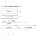
- FIG. 6 is a flowchart showing an example of the operation of the information processing device 100.
- the information processing device 100 determines whether the object to be photographed is a living body or a non-living body such as a photograph based on image data obtained by photographing a person's face. ) Will be explained. As will be described later, when the information processing apparatus 100 acquires image data, it acquires image data with a flash taken with a flash and image data without a flash taken without a flash. Then, the information processing apparatus 100 determines whether or not the imaging target is a living body by comparing the acquired image data with a flash and the image data without a flash.
- Image data such as image data with flash and image data without flash can be used for authentication purposes such as face recognition and iris recognition, for example.
- Image data such as image data with a flash and image data without a flash may be used for purposes other than authentication.
- the information processing device 100 is a device that acquires image data.
- the information processing device 100 in this embodiment is, for example, a portable terminal such as a smartphone.
- the information processing device 100 may be a device other than the illustrated portable terminal.
- FIG. 1 shows an example of the configuration of the information processing device 100.
- the information processing apparatus 100 has, for example, an imaging unit 110, a screen display unit 120, a storage unit 130, and an arithmetic processing unit 140 as constituent elements.
- the image pickup unit 110 acquires image data in response to an instruction from the image acquisition unit 141. Further, when acquiring image data, the imaging unit 110 can use a flash function using the screen display unit 120, which will be described later, a clock function of the information processing device 100, and the like.
- the imaging unit 110 may be a camera or the like preliminarily incorporated in the information processing device 100.
- the imaging unit 110 continuously acquires image data in a flash-fired state and image data in a non-flash-fired state in response to an instruction from the image acquisition unit 141. Can be done. That is, the image pickup unit 110 can continuously acquire the image data with a flash and the image data without a flash, for example, at predetermined predetermined intervals.
- the screen display unit 120 is a display device that displays an image in response to an instruction from the arithmetic processing unit 140.
- the screen display unit 120 may be a touch panel or the like that detects an operator's operation on the screen display unit 120 and outputs the operation to the arithmetic processing unit 140.
- the screen display unit 120 can function as a flash by increasing the brightness value of the image to be displayed on the screen display unit 120 when the imaging unit 110 acquires the image data.
- the screen display unit 120 serves as a flash by displaying a white image in which the brightness value is higher than a predetermined value (for example, the maximum value that can be set) in response to an instruction from the image acquisition unit 141.
- a predetermined value for example, the maximum value that can be set
- FIG. 2 shows an example of the arrangement of the imaging unit 110 and the screen display unit 120.
- the imaging unit 110 and the screen display unit 120 are arranged on the same surface of the information processing device 100.
- the imaging unit 110 is arranged above the rectangular screen display unit 120. If the image pickup unit 110 and the screen display unit 120 have a positional relationship in which the flash moves into the eye to be photographed when the flash is fired to acquire image data, the positional relationship other than that illustrated in FIG. 2 is used. It doesn't matter if there is.
- the storage unit 130 is a storage device such as a hard disk or a memory.
- the storage unit 130 stores processing information, a program 133, and the like necessary for various processes in the arithmetic processing unit 140.
- the program 133 realizes various processing units by being read and executed by the arithmetic processing unit 140.
- the program 133 is read in advance from an external device, a recording medium, or the like via the data input / output function of the information processing device 100, and is stored in the storage unit 130.
- the main information stored in the storage unit 130 includes, for example, image information 131 with a flash and image information 132 without a flash.
- the image information 131 with a flash includes the image data with a flash, which is the image data acquired by the imaging unit 110 by firing the flash.
- the flashed image information 131 includes flashed image data acquired by the imaging unit 110 with the brightness value of the image displayed on the screen display unit 120 increased.
- the image information 131 with a flash the image data with a flash and the information indicating the time when the image data with the flash is acquired by the imaging unit 110 are associated with each other.
- a flash is generated at the eye portion in the image data with the flash. It will be reflected.
- the shape of the screen display unit 120 is a rectangular shape, as shown in FIG. 3, a rectangular flash is reflected in the acquired image data (image data with a flash).
- the non-flash image information 132 includes the non-flash image data which is the image data acquired by the imaging unit 110 without firing the flash.
- the non-flash image data and the information indicating the time when the imaging unit 110 acquired the non-flash image data are associated with each other.
- the arithmetic processing unit 140 has a microprocessor such as an MPU and its peripheral circuits, and by reading and executing the program 133 from the storage unit 130, the hardware and the program 133 are made to cooperate to realize various processing units. do.
- the main processing units realized by the arithmetic processing unit 140 include, for example, an image acquisition unit 141, an extraction unit 142, and a comparison determination unit 143.
- the image acquisition unit 141 instructs the image pickup unit 110 to acquire image data, and also acquires the image data from the image pickup unit 110. Further, the image acquisition unit 141 controls the flash using the screen display unit 120.
- the image acquisition unit 141 instructs the image pickup unit 110 to continuously acquire two types of image data, an image data with a flash and an image data without a flash. Further, the image acquisition unit 141 acquires image data with a flash from the image pickup unit 110 and also acquires image data without a flash. Then, the image acquisition unit 141 stores the acquired image data with a flash in the storage unit 130 as the image information 131 with a flash in association with the time when the image data with the flash is acquired by the imaging unit 110 or the like. Further, the image acquisition unit 141 stores the acquired image data without flash in the storage unit 130 as image information 131 with flash in association with the time when the image data without flash is acquired by the imaging unit 110 or the like.
- the image acquisition unit 141 acquires a pair of image data including image data with a flash and image data without a flash.
- the extraction unit 142 extracts at least the pupil region of the eye portion from the image data such as the image data with flash and the image data without flash. For example, the extraction unit 142 extracts a region other than the white of the eye, such as an iris region and a pupil region, from image data such as image data with a flash and image data without a flash.
- the extraction unit 142 can use the processing result of the face authentication process when extracting the predetermined area.
- the center point of the pupil can be taken. Therefore, the extraction unit 142 is configured to extract the above-mentioned region by, for example, extracting a circular region having a predetermined size predetermined from the center point of the pupil specified by the face recognition process. Can be done.
- the extraction unit 142 may be configured to extract a predetermined region based on, for example, color information such as RGB.
- the comparison determination unit 143 compares predetermined areas extracted by the extraction unit 142 from the pair of image data, the image data with a flash and the image data without a flash. For example, the comparison determination unit 143 performs black and white binarization processing on each region extracted by the extraction unit 142. Then, the comparison determination unit 143 is based on the result of comparing the result of binarizing the image data with flash and the result of binarizing the image data without flash, and the image data with flash, which is a pair of image data. It is determined whether or not the subject to be photographed with the flashless image data is a living body.
- the comparison determination unit 143 calculates the ratio of black and white in the region extracted from the image data with flash and the ratio of black and white in the region extracted from the image data without flash. For example, the comparison determination unit 143 calculates at least one of the ratio of white in each region and the ratio of black in each region. Then, the comparison determination unit 143 determines whether or not the imaging target is a living body based on the result of comparing the calculated ratios. Specifically, for example, when the difference between the black-and-white ratio in the region extracted from the image data with flash and the black-and-white ratio in the region extracted from the image data without flash is equal to or more than a predetermined comparison threshold value, comparison is performed. The determination unit 143 determines that the imaging target is a living body.
- the comparison determination unit 143 determines. It is determined that the object to be imaged is not a living body.
- the flash when the eyes of a living body are photographed, the flash is reflected in the image data with a flash, but the flash is not reflected in the image data without a flash. Therefore, the ratio of black and white when the area is binarized varies between the image data with flash and the image data without flash.
- the flash in the case of a photograph taken with a flash in advance, the flash is reflected in both the image data with the flash and the image data without the flash. Further, in the case of a photograph taken in advance without a flash, the flash is not reflected in both the image data with the flash and the image data without the flash.
- the comparison determination unit 143 can easily determine whether or not the imaging target is a living body by comparing the image data with the flash with the image data without the flash. You can.
- the specific values of the threshold value and the comparison threshold value when binarizing the region are not particularly limited.
- the threshold value for binarization and the comparison threshold value may be set arbitrarily.
- the threshold value and the comparison threshold value at the time of binarization may be, for example, a preset fixed value or a fluidly fluctuating value.
- the comparison threshold value may be set according to the size of the flash such as the size of the screen display unit 120.
- the image acquisition unit 141 of the information processing apparatus 100 acquires a pair of continuously captured image data with a flash and image data without a flash (step S101).
- the extraction unit 142 extracts at least the pupil region of the eye portion from the image data such as the image data with flash and the image data without flash (step S102). For example, the extraction unit 142 extracts a region other than the white of the eye, such as an iris region and a pupil region, from image data such as image data with a flash and image data without a flash. The extraction unit 142 may use the processing result of the face authentication process when extracting the predetermined area.
- the comparison determination unit 143 compares the areas extracted by the extraction unit 142 from the pair of image data, the image data with flash and the image data without flash. For example, the comparison determination unit 143 performs black and white binarization processing on each region extracted by the extraction unit 142. Then, the comparison determination unit 143 compares the result of binarizing the image data with the flash and the result of binarizing the image data without the flash (step S103).
- step S104 When the difference between the black-and-white ratio in the region extracted from the image data with flash and the black-and-white ratio in the region extracted from the image data without flash is equal to or greater than a predetermined comparison threshold value (step S104, Yes), the comparison determination is made. Part 143 determines that the imaging target is a living body (step S105). On the other hand, when the difference between the black-and-white ratio in the region extracted from the image data with flash and the black-and-white ratio in the region extracted from the image data without flash is less than a predetermined comparison threshold value (step S104, No). The comparison determination unit 143 determines that the imaging target is not a living body (step S106).
- the above is an example of the operation of the information processing device 100.
- the information processing device 100 has a comparison determination unit 143. Further, the information processing apparatus 100 is configured to acquire image data with a flash and image data without a flash. With such a configuration, the comparison determination unit 143 can determine whether or not the imaging target is a living body based on the result of comparing the image data with the flash and the image data without the flash. As a result, with a simple configuration, it is possible to easily determine that the image data is not a living body when an image data such as a photograph is taken, and it is possible to suppress erroneous authentication.
- the information processing device 100 has the image pickup unit 110 .
- the information processing device 100 may be configured to acquire image data from an external camera or the like having a flash function. That is, the information processing device 100 does not necessarily have to have a function as an imaging unit 110.
- a case where the screen display unit 120 is used as a flash has been described.
- the function as a flash may be realized by a function other than the screen display unit 120.
- the present invention may be realized by having a plurality of information processing devices have each function shown in FIG. 1 in a distributed manner.
- the information processing device 100 is a portable terminal such as a smartphone
- the image data with flash and the image data without flash acquired by the information processing device 100 are configured to be transmitted to an external information processing device such as an external determination device.
- the external information processing device can have functions as an extraction unit 142 and a comparison determination unit 143.
- the present invention can be used for purposes other than using a portable terminal such as a smartphone, such as when performing entrance / exit management / opening / closing management of gates, delivery boxes, etc. by face authentication or iris authentication.
- a portable terminal such as a smartphone
- the present invention may be utilized in determining whether or not the object to be imaged is a living body in situations other than those illustrated above (for example, for purposes other than authentication).
- FIG. 7 is a block diagram showing an example of the configuration of the information processing device 200.
- FIG. 8 is a diagram showing an example of a flash pattern.
- FIG. 9 is a diagram showing an example of an eye portion in the image data.
- FIG. 10 is a diagram for explaining an example of processing of the extraction unit 243 and the comparison determination unit 244.
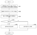
- FIG. 11 is a flowchart showing an example of the operation of the information processing device 200.
- FIG. 12 is a diagram showing another example of the flash pattern.
- the information processing device 200 for determining whether the object to be photographed is a living body or a non-living body such as a photograph by controlling the shape of the flash will be described.
- the information processing apparatus 200 controls the flash pattern, which is the shape control of the flash, when acquiring the image data.
- the information processing apparatus 200 controls the flash pattern by controlling the shape of the flash that is displayed in black instead of white.
- the information processing apparatus 200 determines whether or not the imaging target is a living body based on the shape of the flash reflected in the image data acquired by burning the shape-controlled flash.
- the image data acquired by the information processing device 200 can be used for various purposes such as authentication purposes, like the image data acquired by the information processing device 100.
- the information processing device 200 is a device that acquires image data, like the information processing device 100.
- the information processing device 200 in this embodiment is, for example, a portable terminal such as a smartphone.
- the information processing device 200 may be a device other than the illustrated portable terminal.
- FIG. 7 shows an example of the configuration of the information processing device 200.
- the information processing apparatus 100 includes, for example, an imaging unit 110, a screen display unit 120, a storage unit 230, and an arithmetic processing unit 240 as constituent elements.
- the same components as those of the information processing apparatus 100 described in the first embodiment are designated by the same reference numerals.
- a configuration characteristic of the present embodiment will be described.
- the storage unit 230 is a storage device such as a hard disk or a memory.
- the storage unit 230 stores the processing information and the program 233 required for various processes in the arithmetic processing unit 240.
- the program 233 realizes various processing units by being read and executed by the arithmetic processing unit 240.
- the program 233 is read in advance from an external device, a recording medium, or the like via the data input / output function of the information processing device 200, and is stored in the storage unit 230.
- the main information stored in the storage unit 230 includes, for example, flash pattern information 231 and image information 232.
- the flash pattern information 231 includes information indicating a flash pattern.
- the information indicating the flash pattern and the information indicating the time are associated with each other.
- the screen display unit 120 functions as a flash by displaying a white image in which the brightness value is higher than a predetermined value
- a black pattern can be displayed on the screen instead of simply making the entire surface white.
- FIG. 8 when the screen display unit 120 functions as a flash, a black donut shape can be displayed.
- the flash pattern can be displayed when the screen display unit 120 functions as a flash.
- the information indicating the flash pattern indicates information for specifying the flash pattern used when firing the flash, such as a donut shape.
- the flash pattern may be a shape other than a donut shape, such as a round shape, a square shape, a triangular shape, or another shape.
- the image information 232 includes image data acquired by the imaging unit 110 by firing a flash according to a predetermined flash pattern.
- the image data and the information indicating the time when the image data is acquired by the imaging unit 110 are associated with each other.
- the arithmetic processing unit 240 has a microprocessor such as an MPU and its peripheral circuits, and by reading and executing the program 233 from the storage unit 230, the hardware and the program 233 are made to cooperate to realize various processing units. do.
- the main processing units realized by the arithmetic processing unit 240 include, for example, a flash pattern control unit 241, an image acquisition unit 242, an extraction unit 243, and a comparison determination unit 244.
- the flash pattern control unit 241 determines the flash pattern when the flash is fired. In other words, the flash pattern control unit 241 determines a shape to be displayed in black on the screen display unit 120 when the flash is fired, for example, a round shape, a square shape, a triangular shape, or a donut shape. Then, the flash pattern control unit 241 instructs the screen display unit 120 to fire the flash with the determined flash pattern. Further, the flash pattern control unit 241 stores the determined flash pattern and the information indicating the time in the storage unit 230 as the flash pattern information 231 in association with each other.
- the flash pattern control unit 241 instructs the screen display unit 120 to make a difference in the brightness values in the image displayed on the screen display unit 120, thereby realizing that the flash is fired using the determined flash pattern. do.
- the timing of determining and controlling the flash pattern by the flash pattern control unit 241 is not particularly limited.
- the flash pattern control unit 241 can be configured to determine and control the flash pattern each time the image acquisition unit 242 acquires image data. Further, the flash pattern control unit 241 may be configured to determine and control the flash pattern at predetermined intervals, for example.
- the method of determining the flash pattern by the flash pattern control unit 241 is not particularly limited.
- the flash pattern control unit 241 can be configured to determine a flash pattern to be used from a plurality of predetermined flash patterns.
- the flash pattern control unit 241 may be configured to generate a flash pattern each time by a known algorithm.
- the flash pattern control unit 241 may be configured to determine, for example, a flash pattern including an intermediate luminance value in addition to the flash pattern represented by black.
- the image acquisition unit 242 instructs the image pickup unit 110 to acquire image data, and acquires image data from the image pickup unit 110. Further, the image acquisition unit 242 controls the flash using the screen display unit 120. In the case of the present embodiment, for example, when acquiring image data, the flash is always fired.
- the image acquisition unit 242 instructs the image pickup unit 110 to acquire image data. Further, the image acquisition unit 242 acquires image data acquired in a state where the flash is fired by the flash pattern determined by the flash pattern control unit 241. Then, the image acquisition unit 242 stores the acquired image data in the storage unit 230 as image information 232 in association with the time when the image data is acquired by the image pickup unit 110 or the like.
- the extraction unit 243 extracts a flash pattern from the image data. For example, when image data is acquired in a state where the flash is fired using the flash pattern as shown in FIG. 8, as shown in FIG. 9, a flash pattern surrounded by an area corresponding to the flash is projected in the pupil region. Will be. Therefore, the extraction unit 243 extracts the flash pattern in the image data as shown in FIG.
- the extraction unit 243 extracts the pupil region in the same manner as the extraction unit 142 described in the first embodiment.
- the extraction unit 243 specifies a flash region in the pupil region corresponding to the flash.
- the extraction unit 243 extracts the flash pattern in the specified flash area. For example, in the case shown in FIG. 9, as shown in FIG. 10, the extraction unit 243 extracts a donut-shaped flash pattern existing in the rectangular flash area.
- the comparison determination unit 244 compares the flash pattern extracted by the extraction unit 243 with the flash pattern information 231. Then, the comparison determination unit 244 determines whether or not the imaging target is a living body based on the comparison result.
- the comparison determination unit 244 acquires the flash pattern extracted by the extraction unit 243 from the extraction unit 243. Further, the comparison determination unit 244 acquires the information corresponding to the time when the image data is acquired from the flash pattern information 231. Then, the comparison determination unit 244 compares the flash pattern acquired from the extraction unit 243 with the corresponding information included in the flash pattern information 231.
- the comparison determination unit 244 determines that the imaging target is a living body. ..
- the comparison determination unit 143 determines that the imaging target is not a living body.
- the flash pattern acquired from the extraction unit 243 shows a donut shape.
- the flash pattern indicated by the corresponding information included in the flash pattern information 231 also shows a donut shape. Therefore, the comparison determination unit 244 determines that the imaging target is a living body based on the agreement between the flash pattern acquired from the extraction unit 243 and the flash pattern indicated by the corresponding information included in the flash pattern information 231.
- the image acquisition unit 242 of the information processing apparatus 200 acquires the image data acquired in a state where the flash is fired by the flash pattern determined by the flash pattern control unit 241 (step S201).
- the extraction unit 243 extracts a flash pattern from the image data (step S202). For example, the extraction unit 243 specifies a flash area corresponding to the flash in the image data, and extracts a flash pattern in the specified flash area.
- the comparison determination unit 244 compares the flash pattern extracted by the extraction unit 243 with the flash pattern indicated by the corresponding information included in the flash pattern information 231 (step S203). When the flash pattern extracted by the extraction unit 243 and the flash pattern indicated by the corresponding information included in the flash pattern information 231 match (step S204, Yes), the comparison determination unit 244 determines that the imaging target is a living body. Determine (step S205). On the other hand, when the flash pattern extracted by the extraction unit 243 and the flash pattern indicated by the corresponding information included in the flash pattern information 231 do not match (step S204, No), the comparison determination unit 255 does not have a living body. (Step S206).
- the above is an example of the operation of the information processing device 200.
- the information processing device 200 has a flash pattern control unit 241 and a comparison determination unit 244. Further, the information processing apparatus 200 is configured to acquire image data acquired in a state where the flash is fired by the flash pattern determined by the flash pattern control unit 241.
- the comparison determination unit 244 compares the flash pattern extracted by the extraction unit 243 with the flash pattern indicated by the corresponding information included in the flash pattern information 231, and the imaging target is a living body based on the result of comparison. It is possible to determine whether or not it is. As a result, with a simple configuration, it is possible to easily determine that the image data is not a living body when an image data such as a photograph is taken, and it is possible to suppress erroneous authentication.
- the information processing device 200 described in the present embodiment can employ various modified examples in the same manner as the information processing device 100 described in the first embodiment.
- the information processing device 200 may be configured to acquire image data from an external camera or the like having a flash function, or the function as a flash may be realized by a device other than the screen display unit 120.
- the function as the information processing device 200 may be realized by a plurality of information processing devices.
- the flash pattern may be determined by, for example, the shape of the flash itself.
- a flash pattern may be determined by using a flash device such as a donut type.
- the comparison determination unit 244 compares a predetermined flash pattern according to the shape of the flash device with the flash pattern extracted by the extraction unit 243. It may be configured to determine whether or not the imaging target is a living body.
- the function as the information processing device 200 described in the present embodiment and the function as the information processing device 100 described in the first embodiment may be combined.
- the information processing apparatus may be configured to acquire image data with a flash and image data without a flash acquired in a predetermined flash pattern.
- the information processing apparatus sets the image to be photographed, for example, when the difference in the black-and-white ratio between the image data with flash and the image data without flash is equal to or more than the comparison threshold value and the flash patterns match. It can be configured to determine that it is a living body.
- FIGS. 13 to 15. 13 and 14 show an example of the configuration of the determination device 300.
- FIG. 15 shows an example of another configuration of the determination device 300.
- FIG. 13 shows an example of the hardware configuration of the determination device 300.
- the determination device 300 has the following hardware configuration as an example.
- -CPU Central Processing Unit
- 301 Arimetic unit
- ROM Read Only Memory
- RAM Random Access Memory
- 303 storage device
- -Program group 304 loaded in RAM 303 -Storage device 305 that stores the program group 304
- a drive device 306 that reads and writes a recording medium 310 external to the information processing device.
- -Communication interface 307 that connects to the communication network 311 outside the information processing device.
- -I / O interface 308 that inputs and outputs data -Bus 309 connecting each component
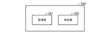
- the determination device 300 can realize the functions as the acquisition unit 321 and the determination unit 322 shown in FIG. 14 by the CPU 301 acquiring the program group 304 and executing the program group 304.
- the program group 304 is stored in the storage device 305 or the ROM 302 in advance, for example, and the CPU 301 loads the program group 304 into the RAM 303 or the like and executes the program group 304 as needed.
- the program group 304 may be supplied to the CPU 301 via the communication network 311 or may be stored in the recording medium 310 in advance, and the drive device 306 may read the program and supply the program to the CPU 301.
- FIG. 13 shows an example of the hardware configuration of the determination device 300.
- the hardware configuration of the determination device 300 is not limited to the above case.
- the determination device 300 may be configured from a part of the above-described configuration, such as not having the drive device 306.
- the acquisition unit 321 acquires the image data with the flash acquired in the state where the flash is fired. Further, the acquisition unit 321 acquires the non-flash image data acquired without firing the flash for the same shooting target as the shooting target reflected in the image data with the flash.
- the acquisition unit 321 acquires the image data with the flash and the image data without the flash.
- the same image target is shown in the image data with a flash and the image data without a flash.
- the acquisition of the image data with rush and the image data without flash by the acquisition unit 321 is continuously performed, for example, at predetermined intervals.
- the determination unit 322 determines the area of the eye to be photographed included in the image data with flash acquired by the acquisition unit 321 and the area of the eye to be photographed included in the image data without flash acquired by the acquisition unit 321. compare. Then, the determination unit 322 determines whether or not the imaging target is a living body based on the comparison result.
- the determination device 300 has an acquisition unit 321 and a determination unit 322. With such a configuration, the determination device 300 can determine whether or not the imaging target is a living body based on the result of comparing the image data with the flash and the image data without the flash acquired by the acquisition unit 321. .. As a result, with a simple configuration, it is possible to easily determine that the image data is not a living body when an image data such as a photograph is taken, and it is possible to suppress erroneous authentication.
- the above-mentioned determination device 300 can be realized by incorporating a predetermined program into the determination device 300.
- the determination device 300 is provided with a flash for the image data with the flash acquired in the state where the flash is fired and the same shooting target as the shooting target reflected in the image data with the flash.
- the acquisition unit 321 that acquires the image data without flash acquired without burning, the area of the eye to be photographed included in the image data with flash acquired by the acquisition unit 321 and the image without flash acquired by the acquisition unit 321.
- This is a program for realizing the determination unit 322 for determining whether or not the imaged object is a living body by comparing the area of the eye of the imaged object included in the data.
- the determination device 300 fires the flash for the image data with the flash acquired in the state where the flash is fired and the same image as the image to be captured in the image data with the flash.
- the image data without flash acquired without burning is acquired, and the area of the eye to be photographed included in the image data with flash is compared with the area of the eye to be photographed included in the image data without flash. This is a method of determining whether or not the imaging target is a living body.
- the object of the present invention can also be realized by a configuration such as the determination device 400.
- the determination device 400 has, for example, an acquisition unit 421 and a determination unit 422.
- the hardware configuration of the determination device 400 may be the same as the hardware configuration of the determination device 300 described with reference to FIG.
- the acquisition unit 421 acquires the image data acquired by firing the flash in a state where the shape of the flash is controlled to be a predetermined flash pattern.
- the determination unit 422 determines whether or not the imaging target is a living body based on the acquired image data.
- the determination device 400 has an acquisition unit 421 and a determination unit 422. Even with such a configuration, as with the determination device 300, it is possible to easily determine that the image data is not a living body when an image data such as a photograph is taken with a simple configuration, and it is possible to suppress erroneous authentication. Is possible. Further, even in the invention of the program for realizing the acquisition unit 421 and the determination unit 422 in the determination device 400 and the determination method performed by the determination device 400, the determination device 400 has the same action and effect as the determination device 400. The above-mentioned object of the present invention can be achieved.
- Appendix 1 An acquisition unit that acquires image data with a flash acquired with the flash fired and image data without a flash acquired without firing the flash for the same image as the image to be photographed reflected in the image data with the flash. By comparing the area of the eye to be photographed included in the image data with a flash and the area of the eye to be photographed included in the image data without a flash, it is determined whether or not the object to be photographed is a living body. Judgment unit and Judgment device having. (Appendix 2) The determination device according to Appendix 1, which is the determination device. The determination unit includes a result of binarizing the eye area of the imaging target included in the image data with flash and a result of binarizing the eye region of the imaging target included in the image data without flash.
- a determination device that determines whether or not the imaging target is a living body by comparing. (Appendix 3) The determination device according to Appendix 1 or Appendix 2. The determination unit determines the ratio of black and white in the region calculated based on the result of binarizing the region of the eye to be photographed included in the image data with flash, and the imaging included in the image data without flash. A determination device for determining whether or not the imaging target is a living body based on the difference between the black-and-white ratio in the region calculated based on the result of binarizing the eye region of the target.
- the determination device determines the ratio of black and white in the region calculated based on the result of binarizing the region of the eye to be imaged included in the image data with flash, and the imaging included in the image data without flash.
- the determination unit determines the ratio of black and white in the region calculated based on the result of binarizing the region of the eye to be imaged included in the image data with flash, and the imaging included in the image data without flash.
- the image data with a flash is image data acquired by firing a flash in a state where the shape of the flash has a predetermined flash pattern.
- Appendix 7) The determination device according to Appendix 6, which is the determination device.
- the determination unit is a determination device that determines whether or not the imaging target is a living body based on the flash pattern extracted by the extraction unit.
- the determination unit is a determination device that determines that the imaging target is a living body when the flash pattern extracted from the image data with a flash is predetermined.
- Information processing device The image data with the flash acquired with the flash fired and the image data without the flash acquired without firing the flash for the same shooting target as the image with the flash reflected in the image data with the flash are acquired.
- the object to be imaged is a living body. Judgment method to judge whether or not. (Appendix 10) For information processing equipment The image data with the flash acquired with the flash fired and the image data without the flash acquired without firing the flash for the same shooting target as the image with the flash reflected in the image data with the flash are acquired. By comparing the area of the eye to be photographed included in the acquired image data with flash and the area of the eye to be photographed included in the acquired image data without flash, the object to be imaged is a living body. A computer-readable recording medium on which a program for realizing the process of determining whether or not the data is recorded is recorded.
- the programs described in each of the above embodiments and appendices may be stored in a storage device or recorded in a computer-readable recording medium.
- the recording medium is a portable medium such as a flexible disk, an optical disk, a magneto-optical disk, and a semiconductor memory.
- Information processing device 110 Imaging unit 120 Screen display unit 130 Storage unit 131 With flash Image information 132 Without flash Image information 133 Program 140 Calculation processing unit 141 Image acquisition unit 142 Extraction unit 143 Comparison judgment unit 200 Information processing device 230 Storage unit 231 Flash Pattern information 232 Image information 240 Calculation processing unit 241 Flash pattern control unit 242 Image acquisition unit 243 Extraction unit 244 Comparison judgment unit 300 Judgment device 301 CPU 302 ROM 303 RAM 304 Program group 305 Storage device 306 Drive device 307 Communication interface 308 Input / output interface 309 Bus 310 Recording medium 311 Communication network 321 Acquisition unit 322 Judgment unit 400 Judgment device 421 Acquisition unit 422 Judgment unit
Landscapes
- Engineering & Computer Science (AREA)
- Theoretical Computer Science (AREA)
- Physics & Mathematics (AREA)
- General Physics & Mathematics (AREA)
- Multimedia (AREA)
- Computer Vision & Pattern Recognition (AREA)
- Health & Medical Sciences (AREA)
- General Health & Medical Sciences (AREA)
- Software Systems (AREA)
- Artificial Intelligence (AREA)
- Human Computer Interaction (AREA)
- Medical Informatics (AREA)
- Life Sciences & Earth Sciences (AREA)
- Ophthalmology & Optometry (AREA)
- Evolutionary Computation (AREA)
- Databases & Information Systems (AREA)
- Computing Systems (AREA)
- Public Health (AREA)
- Heart & Thoracic Surgery (AREA)
- Biomedical Technology (AREA)
- Veterinary Medicine (AREA)
- Pathology (AREA)
- Surgery (AREA)
- Molecular Biology (AREA)
- Animal Behavior & Ethology (AREA)
- Biophysics (AREA)
- Collating Specific Patterns (AREA)
Abstract
判定装置は、フラッシュを焚いた状態で取得したフラッシュあり画像データと、フラッシュあり画像データに映る撮影対象と同一の撮影対象についてフラッシュを焚かずに取得したフラッシュなし画像データと、を取得する取得部と、フラッシュあり画像データ中に含まれる撮影対象の目の領域と、フラッシュなし画像データ中に含まれる撮影対象の目の領域と、を比較することで、撮影対象が生体であるか否か判定する判定部と、を有する。
Description
本発明は、判定装置、判定方法、記録媒体に関する。
顔認証や虹彩認証などの認証技術がある。このような顔認証、虹彩認証などの認証においては、画像データを用いたなりすまし・誤認証が問題となることが知られている。
画像データを用いた際の誤認証を抑制するための技術としては、例えば、特許文献1がある。特許文献1には、被写体をカメラの光軸と同軸で照明して撮影した画像を取得するステップと、画像に写された目が生体の目であるか否かを目の瞳孔領域における輝度値を元にして判定する第2ステップと、を備えた方法が記載されている。また、特許文献1によると、被写体をカメラの光軸と同軸で照明して撮影した第1の画像と、被写体をカメラの光軸と異なる光軸で照明して撮影した第2の画像と、を取得する。そして、第2の画像と第2の画像に写された目が生体の目であるか否かを、生体の目であれば網膜反射が生じることを利用して、目の瞳孔領域における輝度値に基づいて判定する。
特許文献1に記載の技術において1回のみの撮影を行う場合、予め目に照明が映りこんでいる画像などを誤認証するおそれがある。また、特許文献1に記載の技術において2回撮影を行う場合、被写体をカメラの光軸と同軸で照明して撮影するとともに、被写体をカメラの光軸と異なる光軸で照明して撮影することが必要になる。そのため、照明装置を複数用意することが必要となり、その結果、写真などを用いた誤認証を簡易な構成で抑制することが難しい、という課題が生じていた。
そこで、本発明の目的は、写真などを用いた誤認証を簡易な構成で抑制することが難しい、という課題を解決する判定装置、判定方法、記録媒体を提供することにある。
かかる目的を達成するため本発明の一形態である判定装置は、
フラッシュを焚いた状態で取得したフラッシュあり画像データと、前記フラッシュあり画像データに映る撮影対象と同一の撮影対象についてフラッシュを焚かずに取得したフラッシュなし画像データと、を取得する取得部と、
前記フラッシュあり画像データ中に含まれる撮影対象の目の領域と、前記フラッシュなし画像データ中に含まれる撮影対象の目の領域と、を比較することで、撮影対象が生体であるか否か判定する判定部と、
を有する
という構成をとる。
フラッシュを焚いた状態で取得したフラッシュあり画像データと、前記フラッシュあり画像データに映る撮影対象と同一の撮影対象についてフラッシュを焚かずに取得したフラッシュなし画像データと、を取得する取得部と、
前記フラッシュあり画像データ中に含まれる撮影対象の目の領域と、前記フラッシュなし画像データ中に含まれる撮影対象の目の領域と、を比較することで、撮影対象が生体であるか否か判定する判定部と、
を有する
という構成をとる。
また、本発明の他の形態である判定方法は、
情報処理装置が、
フラッシュを焚いた状態で取得したフラッシュあり画像データと、前記フラッシュあり画像データに映る撮影対象と同一の撮影対象についてフラッシュを焚かずに取得したフラッシュなし画像データと、を取得し、
取得した前記フラッシュあり画像データ中に含まれる撮影対象の目の領域と、取得した前記フラッシュなし画像データ中に含まれる撮影対象の目の領域と、を比較することで、撮影対象が生体であるか否か判定する
という構成をとる。
情報処理装置が、
フラッシュを焚いた状態で取得したフラッシュあり画像データと、前記フラッシュあり画像データに映る撮影対象と同一の撮影対象についてフラッシュを焚かずに取得したフラッシュなし画像データと、を取得し、
取得した前記フラッシュあり画像データ中に含まれる撮影対象の目の領域と、取得した前記フラッシュなし画像データ中に含まれる撮影対象の目の領域と、を比較することで、撮影対象が生体であるか否か判定する
という構成をとる。
また、本発明の他の形態である記録媒体は、
情報処理装置に、
フラッシュを焚いた状態で取得したフラッシュあり画像データと、前記フラッシュあり画像データに映る撮影対象と同一の撮影対象についてフラッシュを焚かずに取得したフラッシュなし画像データと、を取得し、
取得した前記フラッシュあり画像データ中に含まれる撮影対象の目の領域と、取得した前記フラッシュなし画像データ中に含まれる撮影対象の目の領域と、を比較することで、撮影対象が生体であるか否か判定する
処理を実現するためのプログラムを記録した、コンピュータが読み取り可能な記録媒体である。
情報処理装置に、
フラッシュを焚いた状態で取得したフラッシュあり画像データと、前記フラッシュあり画像データに映る撮影対象と同一の撮影対象についてフラッシュを焚かずに取得したフラッシュなし画像データと、を取得し、
取得した前記フラッシュあり画像データ中に含まれる撮影対象の目の領域と、取得した前記フラッシュなし画像データ中に含まれる撮影対象の目の領域と、を比較することで、撮影対象が生体であるか否か判定する
処理を実現するためのプログラムを記録した、コンピュータが読み取り可能な記録媒体である。
本発明は、以上のように構成されることにより、写真などを用いた誤認証を簡易な構成で抑制することが可能な判定装置、判定方法、記録媒体を提供することが可能となる。
[第1の実施形態]
本発明の第1の実施形態について図1から図6までを参照して説明する。図1は、情報処理装置100の構成の一例を示すブロック図である。図2は、撮像部110と画面表示部120の配置例を示す図である。図3は、フラッシュあり画像データにおける目の部分の一例を示す図である。図4は、フラッシュなし画像データにおける目の部分の一例を示す図である。図5は、生体の目である場合と写真である場合のフラッシュあり画像データとフラッシュなし画像データの一例を示す図である。図6は、情報処理装置100の動作の一例を示すフローチャートである。
本発明の第1の実施形態について図1から図6までを参照して説明する。図1は、情報処理装置100の構成の一例を示すブロック図である。図2は、撮像部110と画面表示部120の配置例を示す図である。図3は、フラッシュあり画像データにおける目の部分の一例を示す図である。図4は、フラッシュなし画像データにおける目の部分の一例を示す図である。図5は、生体の目である場合と写真である場合のフラッシュあり画像データとフラッシュなし画像データの一例を示す図である。図6は、情報処理装置100の動作の一例を示すフローチャートである。
本発明の第1の実施形態では、人物の顔を撮影した画像データに基づいて、撮影対象が生体であるか、または、写真など生体以外であるか、を判定する情報処理装置100(判定装置)について説明する。後述するように、情報処理装置100は、画像データを取得する際、フラッシュありで撮影したフラッシュあり画像データと、フラッシュなしで撮影したフラッシュなし画像データと、を取得する。そして、情報処理装置100は、取得したフラッシュあり画像データとフラッシュなし画像データとを比較することで、撮影対象が生体であるか否かを判定する。
なお、フラッシュあり画像データやフラッシュなし画像データなどの画像データは、例えば、顔認証や虹彩認証などの認証目的で用いることが出来る。フラッシュあり画像データやフラッシュなし画像データなどの画像データは、認証目的以外に利用されても構わない。
情報処理装置100は、画像データを取得する装置である。本実施形態における情報処理装置100は、例えば、スマートフォンなどの携帯型端末である。情報処理装置100は、例示した携帯型端末以外の装置であっても構わない。
図1は、情報処理装置100の構成の一例を示している。図1を参照すると、情報処理装置100は、構成要素として、例えば、撮像部110と、画面表示部120と、記憶部130と、演算処理部140と、を有している。
撮像部110は、画像取得部141からの指示に応じて、画像データを取得する。また、撮像部110は、画像データを取得する際、後述する画面表示部120を利用したフラッシュ機能や情報処理装置100が有する時計機能などを利用することが出来る。例えば、撮像部110は、情報処理装置100に予め組み込まれたカメラなどであって構わない。
後述するように、撮像部110は、画像取得部141からの指示に応じて、フラッシュを焚いた状態での画像データの取得と、フラッシュを焚かない状態での画像データの取得と、を連続的に行うことが出来る。つまり、撮像部110はフラッシュあり画像データとフラッシュなし画像データとを、例えば予め定められた所定の間隔で、連続的に取得することが出来る。
画面表示部120は、演算処理部140からの指示に応じて画像を表示する表示装置である。画面表示部120は、当該画面表示部120に対するオペレータの操作を検出して演算処理部140に出力するタッチパネルなどであっても構わない。
また、画面表示部120は、撮像部110が画像データを取得する際、画面表示部120上に表示させる画像の輝度値を上げることでフラッシュとして機能することが出来る。例えば、画面表示部120は、画像取得部141からの指示に応じて、輝度値を所定値より高めた(例えば、設定可能な最高値にした)白色の画像を表示することなどにより、フラッシュとして機能することが出来る。
図2は、撮像部110と画面表示部120との配置の一例を示している。例えば、図2で示すように、撮像部110と画面表示部120とは、情報処理装置100の同一面上に配置されている。例えば、図2の場合、長方形形状の画面表示部120の上方に撮像部110が配置されている。なお、撮像部110と画面表示部120とは、フラッシュを焚いて画像データを取得した際に撮影対象の目にフラッシュが移りこむ位置関係であるならば、図2で例示した以外の位置関係であっても構わない。
記憶部130は、ハードディスクやメモリなどの記憶装置である。記憶部130は、演算処理部140における各種処理に必要な処理情報やプログラム133などを記憶する。プログラム133は、演算処理部140に読み込まれて実行されることにより各種処理部を実現する。プログラム133は、情報処理装置100が有するデータ入出力機能を介して外部装置や記録媒体などから予め読み込まれ、記憶部130に保存されている。記憶部130で記憶される主な情報としては、例えば、フラッシュあり画像情報131と、フラッシュなし画像情報132と、がある。
フラッシュあり画像情報131は、撮像部110がフラッシュを焚いて取得した画像データであるフラッシュあり画像データを含んでいる。換言すると、フラッシュあり画像情報131には、画面表示部120に表示される画像の輝度値を上げた状態で撮像部110が取得したフラッシュあり画像データが含まれている。例えば、フラッシュあり画像情報131では、フラッシュあり画像データと、フラッシュあり画像データを撮像部110が取得した時刻を示す情報と、が対応付けられている。
なお、例えば図2で示すような撮像部110と画面表示部120との位置関係において、フラッシュを焚いて生体を撮影すると、図3で示すように、フラッシュあり画像データにおける目の部分にフラッシュが映りこむことになる。例えば、画面表示部120の形状が長方形形状である場合、図3で示すように、取得した画像データ(フラッシュあり画像データ)には長方形形状のフラッシュが映りこむ。
フラッシュなし画像情報132は、撮像部110がフラッシュを焚かずに取得した画像データであるフラッシュなし画像データを含んでいる。例えば、フラッシュなし画像情報132では、フラッシュなし画像データと、フラッシュなし画像データを撮像部110が取得した時刻を示す情報と、が対応付けられている。
なお、フラッシュなしで生体を撮影した場合、図4で示すように、図3を参照して説明したフラッシュありの場合と異なり、目の部分にフラッシュが映りこまない。
演算処理部140は、MPUなどのマイクロプロセッサとその周辺回路を有し、記憶部130からプログラム133を読み込んで実行することにより、上記ハードウェアとプログラム133とを協働させて各種処理部を実現する。演算処理部140で実現される主な処理部としては、例えば、画像取得部141と、抽出部142と、比較判定部143と、がある。
画像取得部141は、撮像部110に対して画像データを取得するよう指示するとともに、撮像部110から画像データを取得する。また、画像取得部141は、画面表示部120を利用したフラッシュの制御を行う。
例えば、画像取得部141は、フラッシュあり画像データと、フラッシュなし画像データと、の2種類の画像データを連続で取得するよう撮像部110に対して指示する。また、画像取得部141は、撮像部110からフラッシュあり画像データを取得するとともに、フラッシュなし画像データを取得する。そして、画像取得部141は、取得したフラッシュあり画像データを、当該フラッシュあり画像データを撮像部110が取得した時刻などと関連付けて、フラッシュあり画像情報131として記憶部130に格納する。また、画像取得部141は、取得したフラッシュなし画像データを、当該フラッシュなし画像データを撮像部110が取得した時刻などと関連付けて、フラッシュあり画像情報131として記憶部130に格納する。
例えば、以上のように、画像取得部141は、フラッシュあり画像データとフラッシュなし画像データとからなる一対の画像データを取得する。
抽出部142は、フラッシュあり画像データやフラッシュなし画像データなどの画像データから、目の部分のうちの少なくとも瞳孔領域を抽出する。例えば、抽出部142は、フラッシュあり画像データやフラッシュなし画像データなどの画像データから、虹彩領域や瞳孔領域などの白目以外の領域を抽出する。
例えば、抽出部142は、上記所定領域の抽出を行う際、顔認証処理の処理結果を利用することが出来る。顔認証処理によると、例えば、瞳の中心点をとることが出来る。そこで、抽出部142は、例えば、顔認証処理により特定された瞳の中心点から予め定められた所定の大きさを有する円状の領域を抽出することで、上記領域の抽出を行うよう構成することが出来る。抽出部142は、例えば、RGBなどの色情報などに基づいて所定領域を抽出するよう構成しても構わない。
比較判定部143は、一対の画像データであるフラッシュあり画像データとフラッシュなし画像データとから抽出部142がそれぞれ抽出した所定領域の比較を行う。例えば、比較判定部143は、抽出部142が抽出したそれぞれの領域に対して、白黒の2値化処理を行う。そして、比較判定部143は、フラッシュあり画像データを2値化した結果と、フラッシュなし画像データを2値化した結果と、を比較した結果に基づいて、一対の画像データであるフラッシュあり画像データとフラッシュなし画像データとの撮影対象が、生体である否かを判定する。
例えば、比較判定部143は、フラッシュあり画像データから抽出した領域における白黒の割合と、フラッシュなし画像データから抽出した領域における白黒の割合と、を算出する。例えば、比較判定部143は、各領域において白が占める割合、各領域において黒が占める割合、のうちの少なくとも一方を算出する。そして、比較判定部143は、算出した割合を比較した結果に基づいて、撮影対象が生体であるか否かを判定する。具体的には、例えば、フラッシュあり画像データから抽出した領域における白黒の割合と、フラッシュなし画像データから抽出した領域における白黒の割合と、の差が予め定められた比較閾値以上である場合、比較判定部143は、撮影対象が生体であると判定する。一方、フラッシュあり画像データから抽出した領域における白黒の割合と、フラッシュなし画像データから抽出した領域における白黒の割合と、の差が予め定められた比較閾値未満である場合、比較判定部143は、撮影対象が生体でないと判定する。
ここで、図5で示すように、生体の目を撮影した場合、フラッシュあり画像データにはフラッシュが映りこむ一方で、フラッシュなし画像データにはフラッシュが映りこまない。そのため、フラッシュあり画像データとフラッシュなし画像データとで、領域を2値化した際の白黒の割合が変動することとなる。一方、予めフラッシュありで撮影した写真の場合、フラッシュあり画像データとフラッシュなし画像データの両方において、フラッシュが映りこむこととなる。また、予めフラッシュなしで撮影した写真の場合、フラッシュあり画像データとフラッシュなし画像データの両方において、フラッシュが映りこまないこととなる。つまり、写真を用いるなど生体以外である場合、フラッシュあり画像データとフラッシュなし画像データとの間に、差が生じないこととなる。以上のような関係のため、上述したように比較判定部143がフラッシュあり画像データとフラッシュなし画像データとの比較を行うことで、撮影対象が生体であるか否かを容易に判定することが出来る。
なお、本実施形態においては、領域を2値化する際の閾値や比較閾値の具体的な値については、特に限定しない。2値化する際の閾値や比較閾値は、任意に設定して構わない。また、2値化する際の閾値や比較閾値は、例えば、予め設定された固定値であっても構わないし、流動的に変動する値であっても構わない。例えば、比較閾値は、画面表示部120の大きさなどフラッシュの大きさなどに応じて定められても構わない。
以上が、情報処理装置100の構成の一例である。続いて、図6を参照して、情報処理装置100の動作の一例について説明する。
図6を参照すると、情報処理装置100の画像取得部141は、連続的に撮影された一対のフラッシュあり画像データとフラッシュなし画像データとを取得する(ステップS101)。
抽出部142は、フラッシュあり画像データやフラッシュなし画像データなどの画像データから、目の部分のうちの少なくとも瞳孔領域を抽出する(ステップS102)。例えば、抽出部142は、フラッシュあり画像データやフラッシュなし画像データなどの画像データから、虹彩領域や瞳孔領域などの白目以外の領域を抽出する。なお、抽出部142は、上記所定領域の抽出を行う際、顔認証処理の処理結果を利用しても構わない。
比較判定部143は、一対の画像データであるフラッシュあり画像データとフラッシュなし画像データとから抽出部142がそれぞれ抽出した領域の比較を行う。例えば、比較判定部143は、抽出部142が抽出したそれぞれの領域に対して、白黒の2値化処理を行う。そして、比較判定部143は、フラッシュあり画像データを2値化した結果と、フラッシュなし画像データを2値化した結果と、を比較する(ステップS103)。
フラッシュあり画像データから抽出した領域における白黒の割合と、フラッシュなし画像データから抽出した領域における白黒の割合と、の差が予め定められた比較閾値以上である場合(ステップS104、Yes)、比較判定部143は、撮影対象が生体であると判定する(ステップS105)。一方、フラッシュあり画像データから抽出した領域における白黒の割合と、フラッシュなし画像データから抽出した領域における白黒の割合と、の差が予め定められた比較閾値未満である場合(ステップS104、No)、比較判定部143は、撮影対象が生体でないと判定する(ステップS106)。
以上が、情報処理装置100の動作の一例である。
このように、情報処理装置100は、比較判定部143を有している。また、情報処理装置100は、フラッシュあり画像データとフラッシュなし画像データとを取得するよう構成されている。このような構成により、比較判定部143は、フラッシュあり画像データとフラッシュなし画像データとを比較した結果に基づいて、撮影対象が生体であるか否かを判定することが出来る。これにより、簡易な構成で、写真などの画像データを撮影した場合に生体でない旨を容易に判定することが可能となり、誤認証を抑制することが可能となる。
なお、本実施形態においては、情報処理装置100が撮像部110を有する場合について説明した。しかしながら、情報処理装置100は、フラッシュ機能を有する外部のカメラなどから画像データを取得するよう構成しても構わない。つまり、情報処理装置100は、必ずしも撮像部110としての機能を有さなくても構わない。また、本実施形態では、画面表示部120をフラッシュとして用いる場合について説明した。しかしながら、フラッシュとしての機能は画面表示部120以外により実現されても構わない。
また、本実施形態においては、図1で示すように、1台の情報処理装置が各機能を有する場合について説明した。しかしながら、本発明は、複数台の情報処理装置が図1で示す各機能を分散して有することで実現しても構わない。例えば、情報処理装置100がスマートフォンなどの携帯型端末である場合、情報処理装置100が取得したフラッシュあり画像データとフラッシュなし画像データとを外部判定装置などの外部情報処理装置に送信するよう構成しても構わない。このように構成する場合、例えば、外部情報処理装置は、抽出部142と比較判定部143としての機能を有することが出来る。
なお、本発明は、顔認証や虹彩認証などによるゲートや宅配ボックスなどの入退場管理・開閉管理を行う際など、スマートフォンなどの携帯型端末を用いる場合以外にも活用可能である。本発明は、上記例示した以外の場面において(例えば、認証目的以外において)、撮影対象が生体であるか否かを判定する際に活用しても構わない。
[第2の実施形態]
次に、本発明の第2の実施形態について図7から図12までを参照して説明する。図7は、情報処理装置200の構成の一例を示すブロック図である。図8は、フラッシュパターンの一例を示す図である。図9は、画像データにおける目の部分の一例を示す図である。図10は、抽出部243と比較判定部244の処理の一例を説明するための図である。図11は、情報処理装置200の動作の一例を示すフローチャートである。図12は、フラッシュパターンの他の一例を示す図である。
次に、本発明の第2の実施形態について図7から図12までを参照して説明する。図7は、情報処理装置200の構成の一例を示すブロック図である。図8は、フラッシュパターンの一例を示す図である。図9は、画像データにおける目の部分の一例を示す図である。図10は、抽出部243と比較判定部244の処理の一例を説明するための図である。図11は、情報処理装置200の動作の一例を示すフローチャートである。図12は、フラッシュパターンの他の一例を示す図である。
本発明の第2の実施形態では、フラッシュの形状を制御することにより、撮影対象が生体であるか、または、写真など生体以外であるか、を判定する情報処理装置200について説明する。後述するように、情報処理装置200は、画像データを取得する際、フラッシュの形状制御であるフラッシュパターンの制御を行う。例えば、情報処理装置200は、フラッシュのうち白色に表示せず黒色で表示する形状を制御することでフラッシュパターンの制御を行う。そして、情報処理装置200は、形状制御されたフラッシュを焚いて取得した画像データに映りこんでいるフラッシュの形状に基づいて、撮影対象が生体であるか否かを判定する。
なお、情報処理装置200が取得した画像データは、情報処理装置100が取得した画像データと同様に、認証目的など様々な用途に用いることが出来る。
情報処理装置200は、情報処理装置100と同様に、画像データを取得する装置である。本実施形態における情報処理装置200は、例えば、スマートフォンなどの携帯型端末である。情報処理装置200は、例示した携帯型端末以外の装置であっても構わない。
図7は、情報処理装置200の構成の一例を示している。図7を参照すると、情報処理装置100は、構成要素として、例えば、撮像部110と、画面表示部120と、記憶部230と、演算処理部240と、を有している。なお、第1の実施形態で説明した情報処理装置100と同様の構成については、同様の符号を付している。以下、本実施形態に特徴的な構成について説明する。
記憶部230は、ハードディスクやメモリなどの記憶装置である。記憶部230は、演算処理部240における各種処理に必要な処理情報やプログラム233を記憶する。プログラム233は、演算処理部240に読み込まれて実行されることにより各種処理部を実現する。プログラム233は、情報処理装置200が有するデータ入出力機能を介して外部装置や記録媒体などから予め読み込まれ、記憶部230に保存されている。記憶部230で記憶される主な情報としては、例えば、フラッシュパターン情報231と、画像情報232と、がある。
フラッシュパターン情報231は、フラッシュパターンを示す情報を含んでいる。例えば、フラッシュパターン情報231では、フラッシュパターンを示す情報と、時刻を示す情報と、が対応付けられている。
ここで、フラッシュパターンを示す情報についてより詳細に説明する。例えば、第1の実施形態においては、輝度値を所定値より高めた白色の画像を表示することにより画面表示部120をフラッシュとして機能させる場合について説明した。本実施形態の場合、画面表示部120をフラッシュとして機能させる際に、単に全面白色とするのではなく、例えば黒色のパターンを画面表示することが出来る。例えば、図8で示すように、画面表示部120をフラッシュとして機能させる際に、黒色のドーナツ型形状を表示することが出来る。このように、本実施形態の場合、画面表示部120をフラッシュとして機能させる際に、フラッシュパターンを表示することが出来る。フラッシュパターンを示す情報は、ドーナツ形状などフラッシュを焚く際に用いるフラッシュパターンを特定するための情報を示している。なお、フラッシュパターンは、丸型、四角型、三角型、その他形状など、ドーナツ型以外であっても構わない。
画像情報232は、撮像部110が所定のフラッシュパターンによりフラッシュを焚いて取得した画像データを含んでいる。例えば、画像情報232では、画像データと、画像データを撮像部110が取得した時刻を示す情報と、が対応付けられている。
演算処理部240は、MPUなどのマイクロプロセッサとその周辺回路を有し、記憶部230からプログラム233を読み込んで実行することにより、上記ハードウェアとプログラム233とを協働させて各種処理部を実現する。演算処理部240で実現される主な処理部としては、例えば、フラッシュパターン制御部241と、画像取得部242と、抽出部243と、比較判定部244と、がある。
フラッシュパターン制御部241は、フラッシュを焚く際のフラッシュパターンを決定する。換言すると、フラッシュパターン制御部241は、例えば、丸型、四角型、三角型、ドーナツ型など、フラッシュを焚く際に画面表示部120上に黒色で表示する形状を決定する。そして、フラッシュパターン制御部241は、決定したフラッシュパターンでフラッシュを焚くよう画面表示部120に指示する。また、フラッシュパターン制御部241は、決定したフラッシュパターンと、時刻を示す情報と、を対応付けて、フラッシュパターン情報231として記憶部230に格納する。
このように、フラッシュパターン制御部241は、画面表示部120に表示する画像において輝度値に差をつけるよう画面表示部120に指示することで、決定したフラッシュパターンを用いてフラッシュを焚くことを実現する。
なお、本実施形態においては、フラッシュパターン制御部241によるフラッシュパターンの決定・制御のタイミングは、特に限定しない。例えば、フラッシュパターン制御部241は、画像取得部242により画像データを取得するごとに、フラッシュパターンの決定・制御を行うよう構成することが出来る。また、フラッシュパターン制御部241は、例えば、予め定められた間隔でフラッシュパターンの決定・制御を行うよう構成しても構わない。
また、本実施形態においては、フラッシュパターン制御部241によるフラッシュパターンの決定方法についても特に限定しない。例えば、フラッシュパターン制御部241は予め定められた複数のフラッシュパターンの中から用いるフラッシュパターンを決定するよう構成することが出来る。フラッシュパターン制御部241は、既知のアルゴリズムにより都度フラッシュパターンを生成するよう構成しても構わない。
また、フラッシュパターン制御部241は、黒色により表現されるフラッシュパターンの他に、例えば、中間的な輝度値を含むフラッシュパターンを決定するよう構成しても構わない。
画像取得部242は、撮像部110に対して画像データを取得するよう指示するとともに、撮像部110から画像データを取得する。また、画像取得部242は、画面表示部120を利用したフラッシュの制御を行う。本実施形態の場合、例えば、画像データを取得する際、常にフラッシュを焚くものとする。
例えば、画像取得部242は、画像データを取得するよう撮像部110に対して指示する。また、画像取得部242は、フラッシュパターン制御部241が決定したフラッシュパターンによりフラッシュを焚いた状態で取得した画像データを取得する。そして、画像取得部242は、取得した画像データを、当該画像データを撮像部110が取得した時刻などと関連付けて、画像情報232として記憶部230に格納する。
抽出部243は、画像データからフラッシュパターンを抽出する。例えば、図8で示すようなフラッシュパターンを用いてフラッシュを焚いた状態で画像データを取得すると、図9で示すように、瞳孔領域に、フラッシュに相当する領域に囲まれたフラッシュパターンが写されることになる。そこで、抽出部243は、図9で示すような画像データ中のフラッシュパターンを抽出する。
具体的には、例えば、抽出部243は、第1の実施形態で説明した抽出部142と同様に瞳孔領域を抽出する。また、抽出部243は、瞳孔領域中のフラッシュに応じたフラッシュ領域を特定する。そして、抽出部243は、特定したフラッシュ領域中のフラッシュパターンを抽出する。例えば、図9で示す場合、抽出部243は、図10で示すように、長方形形状のフラッシュ領域の中に存在するドーナツ型のフラッシュパターンを抽出する。
比較判定部244は、抽出部243が抽出したフラッシュパターンと、フラッシュパターン情報231と、を比較する。そして、比較判定部244は、比較した結果に基づいて、撮影対象が生体であるか否かを判定する。
例えば、比較判定部244は、抽出部243から当該抽出部243が抽出したフラッシュパターンを取得する。また、比較判定部244は、画像データを取得した時刻と対応する情報をフラッシュパターン情報231から取得する。そして、比較判定部244は、抽出部243から取得したフラッシュパターンと、フラッシュパターン情報231に含まれる対応する情報と、を比較する。
比較の結果、抽出部243から取得したフラッシュパターンと、フラッシュパターン情報231に含まれる対応する情報が示すフラッシュパターンと、が一致する場合、比較判定部244は、撮影対象が生体であると判定する。一方、抽出部243から取得したフラッシュパターンと、フラッシュパターン情報231に含まれる対応する情報が示すフラッシュパターンと、が一致しない場合、比較判定部143は、撮影対象が生体でないと判定する。
例えば、図10で示す場合、抽出部243から取得したフラッシュパターンはドーナツ型を示している。また、フラッシュパターン情報231に含まれる対応する情報が示すフラッシュパターンもドーナツ型を示している。そのため、比較判定部244は、抽出部243から取得したフラッシュパターンと、フラッシュパターン情報231に含まれる対応する情報が示すフラッシュパターンと、の一致により、撮影対象が生体であると判定する。
以上が、情報処理装置200の構成の一例である。続いて、図11を参照して、情報処理装置200の動作の一例について説明する。
図11を参照すると、情報処理装置200の画像取得部242は、フラッシュパターン制御部241が決定したフラッシュパターンによりフラッシュを焚いた状態で取得した画像データを取得する(ステップS201)。
抽出部243は、画像データからフラッシュパターンを抽出する(ステップS202)。例えば、抽出部243は画像データ中のフラッシュに応じたフラッシュ領域を特定して、特定したフラッシュ領域中のフラッシュパターンを抽出する。
比較判定部244は、抽出部243が抽出したフラッシュパターンと、フラッシュパターン情報231に含まれる対応する情報が示すフラッシュパターンと、を比較する(ステップS203)。抽出部243が抽出したフラッシュパターンと、フラッシュパターン情報231に含まれる対応する情報が示すフラッシュパターンと、が一致する場合(ステップS204、Yes)、比較判定部244は、撮影対象が生体であると判定する(ステップS205)。一方、抽出部243が抽出したフラッシュパターンと、フラッシュパターン情報231に含まれる対応する情報が示すフラッシュパターンと、が一致しない場合(ステップS204、No)、比較判定部255は、撮影対象が生体でないと判定する(ステップS206)。
以上が、情報処理装置200の動作の一例である。
このように、情報処理装置200は、フラッシュパターン制御部241と比較判定部244とを有している。また、情報処理装置200は、フラッシュパターン制御部241が決定したフラッシュパターンによりフラッシュを焚いた状態で取得した画像データを取得するよう構成されている。このような構成により、比較判定部244は、抽出部243が抽出したフラッシュパターンと、フラッシュパターン情報231に含まれる対応する情報が示すフラッシュパターンと、を比較した結果に基づいて、撮影対象が生体であるか否かを判定することが出来る。これにより、簡易な構成で、写真などの画像データを撮影した場合に生体でない旨を容易に判定することが可能となり、誤認証を抑制することが可能となる。
なお、本実施形態において説明した情報処理装置200は、第1の実施形態で説明した情報処理装置100と同様に、様々な変形例を採用することが出来る。例えば、情報処理装置200は、フラッシュ機能を有する外部のカメラなどから画像データを取得するよう構成しても構わないし、フラッシュとしての機能を画面表示部120以外により実現しても構わない。また、情報処理装置200としての機能は、複数台の情報処理装置により実現されても構わない。
また、本実施形態においては、フラッシュを焚く際に黒色のパターンを画面表示部120上に表示することでフラッシュパターンを制御する例について説明した。しかしながら、フラッシュパターンは、例えば、フラッシュ自体の形状などにより定められても構わない。例えば、図12で示すように、ドーナツ型などのフラッシュ装置を用いることにより、フラッシュパターンを定めるよう構成しても構わない。また、ドーナツ型などのフラッシュ装置を用いる場合、比較判定部244は、予め定められた、フラッシュ装置の形状に応じたフラッシュパターンと、抽出部243が抽出したフラッシュパターンと、を比較することにより、撮影対象が生体であるか否か判定するよう構成しても構わない。
また、本実施形態で説明した情報処理装置200としての機能と、第1の実施形態で説明した情報処理装置100としての機能と、を組み合わせても構わない。例えば、情報処理装置は、所定のフラッシュパターンで取得したフラッシュあり画像データとフラッシュなし画像データとを取得するよう構成しても構わない。このような構成の場合、情報処理装置は、例えば、フラッシュあり画像データとフラッシュなし画像データとの白黒割合の差が比較閾値以上であり、かつ、フラッシュパターンの一致がある場合に、撮影対象を生体であると判定するよう構成することが出来る。
[第3の実施形態]
次に、本発明の第3の実施形態について、図13から図15までを参照して説明する。図13、図14は、判定装置300の構成の一例を示している。図15は、判定装置300の他の構成の一例を示している。
次に、本発明の第3の実施形態について、図13から図15までを参照して説明する。図13、図14は、判定装置300の構成の一例を示している。図15は、判定装置300の他の構成の一例を示している。
図13は、判定装置300のハードウェア構成の一例を示している。図13を参照すると、判定装置300は、一例として、以下のようなハードウェア構成を有している。
・CPU(Central Processing Unit)301(演算装置)
・ROM(Read Only Memory)302(記憶装置)
・RAM(Random Access Memory)303(記憶装置)
・RAM303にロードされるプログラム群304
・プログラム群304を格納する記憶装置305
・情報処理装置外部の記録媒体310の読み書きを行うドライブ装置306
・情報処理装置外部の通信ネットワーク311と接続する通信インタフェース307
・データの入出力を行う入出力インタフェース308
・各構成要素を接続するバス309
・CPU(Central Processing Unit)301(演算装置)
・ROM(Read Only Memory)302(記憶装置)
・RAM(Random Access Memory)303(記憶装置)
・RAM303にロードされるプログラム群304
・プログラム群304を格納する記憶装置305
・情報処理装置外部の記録媒体310の読み書きを行うドライブ装置306
・情報処理装置外部の通信ネットワーク311と接続する通信インタフェース307
・データの入出力を行う入出力インタフェース308
・各構成要素を接続するバス309
また、判定装置300は、プログラム群304をCPU301が取得して当該CPU301が実行することで、図14に示す取得部321や判定部322としての機能を実現することが出来る。なお、プログラム群304は、例えば、予め記憶装置305やROM302に格納されており、必要に応じてCPU301がRAM303などにロードして実行する。また、プログラム群304は、通信ネットワーク311を介してCPU301に供給されてもよいし、予め記録媒体310に格納されており、ドライブ装置306が該プログラムを読み出してCPU301に供給してもよい。
なお、図13は、判定装置300のハードウェア構成の一例を示している。判定装置300のハードウェア構成は上述した場合に限定されない。例えば、判定装置300は、ドライブ装置306を有さないなど、上述した構成の一部から構成されてもよい。
取得部321は、フラッシュを焚いた状態で取得したフラッシュあり画像データを取得する。また、取得部321は、フラッシュあり画像データに映る撮影対象と同一の撮影対象についてフラッシュを焚かずに取得したフラッシュなし画像データを取得する。
このように、取得部321は、フラッシュあり画像データとフラッシュなし画像データとを取得する。フラッシュあり画像データとフラッシュなし画像データとには、同一の撮影対象が映っている。なお、取得部321によるラッシュあり画像データとフラッシュなし画像データとの取得は、例えば、予め定められた間隔で連続的に行われる。
判定部322は、取得部321が取得したフラッシュあり画像データ中に含まれる撮影対象の目の領域と、取得部321が取得したフラッシュなし画像データ中に含まれる撮影対象の目の領域と、を比較する。そして、判定部322は、比較した結果に基づいて、撮影対象が生体であるか否か判定する。
このように、判定装置300は、取得部321と判定部322とを有している。このような構成により、判定装置300は、取得部321が取得したフラッシュあり画像データとフラッシュなし画像データとを比較した結果に基づいて、撮影対象が生体であるか否かを判定することが出来る。これにより、簡易な構成で、写真などの画像データを撮影した場合に生体でない旨を容易に判定することが可能となり、誤認証を抑制することが可能となる。
なお、上述した判定装置300は、当該判定装置300に所定のプログラムが組み込まれることで実現できる。具体的に、本発明の他の形態であるプログラムは、判定装置300に、フラッシュを焚いた状態で取得したフラッシュあり画像データと、フラッシュあり画像データに映る撮影対象と同一の撮影対象についてフラッシュを焚かずに取得したフラッシュなし画像データと、を取得する取得部321と、取得部321が取得したフラッシュあり画像データ中に含まれる撮影対象の目の領域と、取得部321が取得したフラッシュなし画像データ中に含まれる撮影対象の目の領域と、を比較することで、撮影対象が生体であるか否か判定する判定部322と、実現するためのプログラムである。
また、上述した判定装置300により実行される判定方法は、判定装置300が、フラッシュを焚いた状態で取得したフラッシュあり画像データと、フラッシュあり画像データに映る撮影対象と同一の撮影対象についてフラッシュを焚かずに取得したフラッシュなし画像データと、を取得し、フラッシュあり画像データ中に含まれる撮影対象の目の領域と、フラッシュなし画像データ中に含まれる撮影対象の目の領域と、を比較することで、撮影対象が生体であるか否か判定する、という方法である。
上述した構成を有する、プログラム、又は、判定方法、の発明であっても、上記判定装置300と同様の作用・効果を有するために、上述した本発明の目的を達成することが出来る。
また、本発明の目的は、判定装置400のような構成によっても実現できる。図15を参照すると、判定装置400は、例えば、取得部421と判定部422とを有している。なお、判定装置400のハードウェア構成は、図13を用いて説明した判定装置300のハードウェア構成と同様のもので構わない。
取得部421は、フラッシュの形状が予め定められたフラッシュパターンとなるように制御した状態でフラッシュを焚いて取得した画像データを取得する。判定部422は、取得した画像データに基づいて、撮影対象が生体であるか否か判定する。
このように、判定装置400は、取得部421と判定部422とを有している。このような構成であっても、判定装置300と同様に、簡易な構成で、写真などの画像データを撮影した場合に生体でない旨を容易に判定することが可能となり、誤認証を抑制することが可能となる。また、判定装置400に取得部421と判定部422とを実現するためのプログラムや判定装置400が行う判定方法の発明であっても、上記判定装置400と同様の作用・効果を有するために、上述した本発明の目的を達成することが出来る。
<付記>
上記実施形態の一部又は全部は、以下の付記のようにも記載されうる。以下、本発明における判定装置などの概略を説明する。但し、本発明は、以下の構成に限定されない。
上記実施形態の一部又は全部は、以下の付記のようにも記載されうる。以下、本発明における判定装置などの概略を説明する。但し、本発明は、以下の構成に限定されない。
(付記1)
フラッシュを焚いた状態で取得したフラッシュあり画像データと、前記フラッシュあり画像データに映る撮影対象と同一の撮影対象についてフラッシュを焚かずに取得したフラッシュなし画像データと、を取得する取得部と、
前記フラッシュあり画像データ中に含まれる撮影対象の目の領域と、前記フラッシュなし画像データ中に含まれる撮影対象の目の領域と、を比較することで、撮影対象が生体であるか否か判定する判定部と、
を有する
判定装置。
(付記2)
付記1に記載の判定装置であって、
前記判定部は、前記フラッシュあり画像データ中に含まれる撮影対象の目の領域を2値化した結果と、前記フラッシュなし画像データ中に含まれる撮影対象の目の領域を2値化した結果と、を比較することで、撮影対象が生体であるか否か判定する
判定装置。
(付記3)
付記1または付記2に記載の判定装置であって、
前記判定部は、前記フラッシュあり画像データ中に含まれる撮影対象の目の領域を2値化した結果に基づいて算出される当該領域における白黒の割合と、前記フラッシュなし画像データ中に含まれる撮影対象の目の領域を2値化した結果に基づいて算出される当該領域における白黒の割合と、の差に基づいて、撮影対象が生体であるか否か判定する
判定装置。
(付記4)
付記3に記載の判定装置であって、
前記判定部は、前記フラッシュあり画像データ中に含まれる撮影対象の目の領域を2値化した結果に基づいて算出される当該領域における白黒の割合と、前記フラッシュなし画像データ中に含まれる撮影対象の目の領域を2値化した結果に基づいて算出される当該領域における白黒の割合と、の差が予め定められた比較閾値以上である場合、撮影対象が生体であると判定する
判定装置。
(付記5)
付記3または付記4に記載の判定装置であって、
前記判定部は、前記フラッシュあり画像データ中に含まれる撮影対象の目の領域を2値化した結果に基づいて算出される当該領域における白黒の割合と、前記フラッシュなし画像データ中に含まれる撮影対象の目の領域を2値化した結果に基づいて算出される当該領域における白黒の割合と、の差が予め定められた比較閾値未満である場合、撮影対象が生体でないと判定する
判定装置。
(付記6)
付記1から付記5までのいずれか1項に記載の判定装置であって、
前記フラッシュあり画像データは、フラッシュの形状が所定のフラッシュパターンとなる状態でフラッシュを焚いて取得された画像データである
判定装置。
(付記7)
付記6に記載の判定装置であって、
前記フラッシュあり画像データから前記フラッシュパターンを抽出する抽出部を有し、
前記判定部は、前記抽出部が抽出した前記フラッシュパターンに基づいて、撮影対象が生体であるか否か判定する
判定装置。
(付記8)
付記7に記載の判定装置であって、
前記判定部は、前記フラッシュあり画像データから抽出した前記フラッシュパターンが予め定められたものである場合、撮影対象が生体であると判定する
判定装置。
(付記9)
情報処理装置が、
フラッシュを焚いた状態で取得したフラッシュあり画像データと、前記フラッシュあり画像データに映る撮影対象と同一の撮影対象についてフラッシュを焚かずに取得したフラッシュなし画像データと、を取得し、
取得した前記フラッシュあり画像データ中に含まれる撮影対象の目の領域と、取得した前記フラッシュなし画像データ中に含まれる撮影対象の目の領域と、を比較することで、撮影対象が生体であるか否か判定する
判定方法。
(付記10)
情報処理装置に、
フラッシュを焚いた状態で取得したフラッシュあり画像データと、前記フラッシュあり画像データに映る撮影対象と同一の撮影対象についてフラッシュを焚かずに取得したフラッシュなし画像データと、を取得し、
取得した前記フラッシュあり画像データ中に含まれる撮影対象の目の領域と、取得した前記フラッシュなし画像データ中に含まれる撮影対象の目の領域と、を比較することで、撮影対象が生体であるか否か判定する
処理を実現するためのプログラムを記録した、コンピュータが読み取り可能な記録媒体。
なお、上記各実施形態及び付記において記載したプログラムは、記憶装置に記憶されていたり、コンピュータが読み取り可能な記録媒体に記録されていたりする。例えば、記録媒体は、フレキシブルディスク、光ディスク、光磁気ディスク、及び、半導体メモリ等の可搬性を有する媒体である。
以上、上記各実施形態を参照して本願発明を説明したが、本願発明は、上述した実施形態に限定されるものではない。本願発明の構成や詳細には、本願発明の範囲内で当業者が理解しうる様々な変更をすることが出来る。
なお、本発明は、日本国にて2020年1月30日に特許出願された特願2020-13982の特許出願に基づく優先権主張の利益を享受するものであり、当該特許出願に記載された内容は、全て本明細書に含まれるものとする。
100 情報処理装置
110 撮像部
120 画面表示部
130 記憶部
131 フラッシュあり画像情報
132 フラッシュなし画像情報
133 プログラム
140 演算処理部
141 画像取得部
142 抽出部
143 比較判定部
200 情報処理装置
230 記憶部
231 フラッシュパターン情報
232 画像情報
240 演算処理部
241 フラッシュパターン制御部
242 画像取得部
243 抽出部
244 比較判定部
300 判定装置
301 CPU
302 ROM
303 RAM
304 プログラム群
305 記憶装置
306 ドライブ装置
307 通信インタフェース
308 入出力インタフェース
309 バス
310 記録媒体
311 通信ネットワーク
321 取得部
322 判定部
400 判定装置
421 取得部
422 判定部
Claims (10)
- フラッシュを焚いた状態で取得したフラッシュあり画像データと、前記フラッシュあり画像データに映る撮影対象と同一の撮影対象についてフラッシュを焚かずに取得したフラッシュなし画像データと、を取得する取得部と、
前記フラッシュあり画像データ中に含まれる撮影対象の目の領域と、前記フラッシュなし画像データ中に含まれる撮影対象の目の領域と、を比較することで、撮影対象が生体であるか否か判定する判定部と、
を有する
判定装置。 - 請求項1に記載の判定装置であって、
前記判定部は、前記フラッシュあり画像データ中に含まれる撮影対象の目の領域を2値化した結果と、前記フラッシュなし画像データ中に含まれる撮影対象の目の領域を2値化した結果と、を比較することで、撮影対象が生体であるか否か判定する
判定装置。 - 請求項1または請求項2に記載の判定装置であって、
前記判定部は、前記フラッシュあり画像データ中に含まれる撮影対象の目の領域を2値化した結果に基づいて算出される当該領域における白黒の割合と、前記フラッシュなし画像データ中に含まれる撮影対象の目の領域を2値化した結果に基づいて算出される当該領域における白黒の割合と、の差に基づいて、撮影対象が生体であるか否か判定する
判定装置。 - 請求項3に記載の判定装置であって、
前記判定部は、前記フラッシュあり画像データ中に含まれる撮影対象の目の領域を2値化した結果に基づいて算出される当該領域における白黒の割合と、前記フラッシュなし画像データ中に含まれる撮影対象の目の領域を2値化した結果に基づいて算出される当該領域における白黒の割合と、の差が予め定められた比較閾値以上である場合、撮影対象が生体であると判定する
判定装置。 - 請求項3または請求項4に記載の判定装置であって、
前記判定部は、前記フラッシュあり画像データ中に含まれる撮影対象の目の領域を2値化した結果に基づいて算出される当該領域における白黒の割合と、前記フラッシュなし画像データ中に含まれる撮影対象の目の領域を2値化した結果に基づいて算出される当該領域における白黒の割合と、の差が予め定められた比較閾値未満である場合、撮影対象が生体でないと判定する
判定装置。 - 請求項1から請求項5までのいずれか1項に記載の判定装置であって、
前記フラッシュあり画像データは、フラッシュの形状が所定のフラッシュパターンとなる状態でフラッシュを焚いて取得された画像データである
判定装置。 - 請求項6に記載の判定装置であって、
前記フラッシュあり画像データから前記フラッシュパターンを抽出する抽出部を有し、
前記判定部は、前記抽出部が抽出した前記フラッシュパターンに基づいて、撮影対象が生体であるか否か判定する
判定装置。 - 請求項7に記載の判定装置であって、
前記判定部は、前記フラッシュあり画像データから抽出した前記フラッシュパターンが予め定められたものである場合、撮影対象が生体であると判定する
判定装置。 - 情報処理装置が、
フラッシュを焚いた状態で取得したフラッシュあり画像データと、前記フラッシュあり画像データに映る撮影対象と同一の撮影対象についてフラッシュを焚かずに取得したフラッシュなし画像データと、を取得し、
取得した前記フラッシュあり画像データ中に含まれる撮影対象の目の領域と、取得した前記フラッシュなし画像データ中に含まれる撮影対象の目の領域と、を比較することで、撮影対象が生体であるか否か判定する
判定方法。 - 情報処理装置に、
フラッシュを焚いた状態で取得したフラッシュあり画像データと、前記フラッシュあり画像データに映る撮影対象と同一の撮影対象についてフラッシュを焚かずに取得したフラッシュなし画像データと、を取得し、
取得した前記フラッシュあり画像データ中に含まれる撮影対象の目の領域と、取得した前記フラッシュなし画像データ中に含まれる撮影対象の目の領域と、を比較することで、撮影対象が生体であるか否か判定する
処理を実現するためのプログラムを記録した、コンピュータが読み取り可能な記録媒体。
Priority Applications (2)
| Application Number | Priority Date | Filing Date | Title |
|---|---|---|---|
| US17/791,645 US20230041725A1 (en) | 2020-01-30 | 2020-12-28 | Determination device |
| JP2021574563A JPWO2021153148A1 (ja) | 2020-01-30 | 2020-12-28 |
Applications Claiming Priority (2)
| Application Number | Priority Date | Filing Date | Title |
|---|---|---|---|
| JP2020-013982 | 2020-01-30 | ||
| JP2020013982 | 2020-01-30 |
Publications (1)
| Publication Number | Publication Date |
|---|---|
| WO2021153148A1 true WO2021153148A1 (ja) | 2021-08-05 |
Family
ID=77078524
Family Applications (1)
| Application Number | Title | Priority Date | Filing Date |
|---|---|---|---|
| PCT/JP2020/049165 WO2021153148A1 (ja) | 2020-01-30 | 2020-12-28 | 判定装置 |
Country Status (3)
| Country | Link |
|---|---|
| US (1) | US20230041725A1 (ja) |
| JP (1) | JPWO2021153148A1 (ja) |
| WO (1) | WO2021153148A1 (ja) |
Citations (6)
| Publication number | Priority date | Publication date | Assignee | Title |
|---|---|---|---|---|
| JPH1069536A (ja) * | 1996-08-28 | 1998-03-10 | Sharp Corp | 画像合成装置 |
| JP2000298727A (ja) * | 1999-03-23 | 2000-10-24 | Lg Electronics Inc | 虹彩認識システムの偽造判別方法 |
| JP2001236501A (ja) * | 1999-12-13 | 2001-08-31 | Toyota Motor Corp | 画像認識装置および画像認識方法 |
| JP2007072861A (ja) * | 2005-09-08 | 2007-03-22 | Omron Corp | なりすまし検出装置及び顔認証装置 |
| US20170344793A1 (en) * | 2014-10-22 | 2017-11-30 | Veridium Ip Limited | Systems and methods for performing iris identification and verification using mobile devices |
| WO2019163065A1 (ja) * | 2018-02-22 | 2019-08-29 | 日本電気株式会社 | なりすまし検知装置、なりすまし検知方法、及びコンピュータ読み取り可能な記録媒体 |
-
2020
- 2020-12-28 WO PCT/JP2020/049165 patent/WO2021153148A1/ja active Application Filing
- 2020-12-28 JP JP2021574563A patent/JPWO2021153148A1/ja active Pending
- 2020-12-28 US US17/791,645 patent/US20230041725A1/en active Pending
Patent Citations (6)
| Publication number | Priority date | Publication date | Assignee | Title |
|---|---|---|---|---|
| JPH1069536A (ja) * | 1996-08-28 | 1998-03-10 | Sharp Corp | 画像合成装置 |
| JP2000298727A (ja) * | 1999-03-23 | 2000-10-24 | Lg Electronics Inc | 虹彩認識システムの偽造判別方法 |
| JP2001236501A (ja) * | 1999-12-13 | 2001-08-31 | Toyota Motor Corp | 画像認識装置および画像認識方法 |
| JP2007072861A (ja) * | 2005-09-08 | 2007-03-22 | Omron Corp | なりすまし検出装置及び顔認証装置 |
| US20170344793A1 (en) * | 2014-10-22 | 2017-11-30 | Veridium Ip Limited | Systems and methods for performing iris identification and verification using mobile devices |
| WO2019163065A1 (ja) * | 2018-02-22 | 2019-08-29 | 日本電気株式会社 | なりすまし検知装置、なりすまし検知方法、及びコンピュータ読み取り可能な記録媒体 |
Also Published As
| Publication number | Publication date |
|---|---|
| US20230041725A1 (en) | 2023-02-09 |
| JPWO2021153148A1 (ja) | 2021-08-05 |
Similar Documents
| Publication | Publication Date | Title |
|---|---|---|
| CN111385482B (zh) | 图像处理设备及其控制方法和机器可读介质 | |
| US11948282B2 (en) | Image processing apparatus, image processing method, and storage medium for lighting processing on image using model data | |
| CN107948539B (zh) | 一种闪光灯控制方法及终端 | |
| US20200034631A1 (en) | Image processing apparatus, image processing method, and storage medium | |
| KR101493064B1 (ko) | 고도의 정확성으로 결함이 있는 눈을 검출하는 카메라에 기반한 방법 | |
| CN103294993B (zh) | 用于识别假脸的装置和方法 | |
| US10382734B2 (en) | Electronic device and color temperature adjusting method | |
| US9699386B2 (en) | Image processing apparatus and method | |
| US10057503B2 (en) | Image processing apparatus and method for applying a virtual light source to an image | |
| CN111368819B (zh) | 光斑检测方法和装置 | |
| JP6718253B2 (ja) | 画像処理装置及び画像処理方法 | |
| WO2013114803A1 (ja) | 画像処理装置及びその画像処理方法、並びにコンピュータ・プログラム、および画像処理システム | |
| JP2017157043A (ja) | 画像処理装置、撮像装置、及び、画像処理方法 | |
| JP2020102059A (ja) | 画像処理装置 | |
| WO2021153148A1 (ja) | 判定装置 | |
| WO2021153149A1 (ja) | 判定装置 | |
| CN109040654A (zh) | 外部拍摄设备的识别方法、装置及存储介质 | |
| CN113128254A (zh) | 人脸捕获方法、装置、芯片及计算机可读存储介质 | |
| US20200374420A1 (en) | Image processing apparatus, image processing method, and storage medium | |
| CN112672066A (zh) | 图像处理设备、图像拍摄设备、控制方法及存储介质 | |
| JP2016091376A (ja) | 画像処理装置およびその制御方法、プログラムならびに記録媒体 | |
| WO2013114802A1 (ja) | 画像処理装置及びその画像処理方法、並びにコンピュータ・プログラム、および画像処理システム | |
| JP2017151562A (ja) | 画像処理装置、撮像装置およびこれらの制御方法ならびにプログラム | |
| JP6991750B2 (ja) | 画像処理装置、画像処理方法、及びプログラム | |
| CN104933390A (zh) | 生成皮肤图像的方法、装置以及电子设备 |
Legal Events
| Date | Code | Title | Description |
|---|---|---|---|
| 121 | Ep: the epo has been informed by wipo that ep was designated in this application |
Ref document number: 20916821 Country of ref document: EP Kind code of ref document: A1 |
|
| ENP | Entry into the national phase |
Ref document number: 2021574563 Country of ref document: JP Kind code of ref document: A |
|
| NENP | Non-entry into the national phase |
Ref country code: DE |
|
| 122 | Ep: pct application non-entry in european phase |
Ref document number: 20916821 Country of ref document: EP Kind code of ref document: A1 |