WO2021149632A1 - Portable authentication device, ic card, and authentication system - Google Patents
Portable authentication device, ic card, and authentication system Download PDFInfo
- Publication number
- WO2021149632A1 WO2021149632A1 PCT/JP2021/001453 JP2021001453W WO2021149632A1 WO 2021149632 A1 WO2021149632 A1 WO 2021149632A1 JP 2021001453 W JP2021001453 W JP 2021001453W WO 2021149632 A1 WO2021149632 A1 WO 2021149632A1
- Authority
- WO
- WIPO (PCT)
- Prior art keywords
- card
- authentication
- registrant
- user
- information
- Prior art date
Links
- 238000004891 communication Methods 0.000 claims abstract description 38
- 238000012545 processing Methods 0.000 description 20
- 238000000034 method Methods 0.000 description 19
- 238000012797 qualification Methods 0.000 description 19
- 230000008569 process Effects 0.000 description 18
- 238000010586 diagram Methods 0.000 description 13
- 230000004044 response Effects 0.000 description 10
- 230000006870 function Effects 0.000 description 7
- 101000760620 Homo sapiens Cell adhesion molecule 1 Proteins 0.000 description 3
- 101000661807 Homo sapiens Suppressor of tumorigenicity 14 protein Proteins 0.000 description 3
- 230000004048 modification Effects 0.000 description 3
- 238000012986 modification Methods 0.000 description 3
- 101000911772 Homo sapiens Hsc70-interacting protein Proteins 0.000 description 2
- 101000585359 Homo sapiens Suppressor of tumorigenicity 20 protein Proteins 0.000 description 2
- 102100029860 Suppressor of tumorigenicity 20 protein Human genes 0.000 description 2
- 230000005540 biological transmission Effects 0.000 description 2
- 238000004364 calculation method Methods 0.000 description 2
- 239000000284 extract Substances 0.000 description 2
- 230000007246 mechanism Effects 0.000 description 2
- 101000710013 Homo sapiens Reversion-inducing cysteine-rich protein with Kazal motifs Proteins 0.000 description 1
- 101000661816 Homo sapiens Suppression of tumorigenicity 18 protein Proteins 0.000 description 1
- 125000002066 L-histidyl group Chemical group [H]N1C([H])=NC(C([H])([H])[C@](C(=O)[*])([H])N([H])[H])=C1[H] 0.000 description 1
- 230000008859 change Effects 0.000 description 1
- 230000010365 information processing Effects 0.000 description 1
- 108090000237 interleukin-24 Proteins 0.000 description 1
- 238000004519 manufacturing process Methods 0.000 description 1
- 239000007787 solid Substances 0.000 description 1
Images


Classifications
-
- G—PHYSICS
- G06—COMPUTING; CALCULATING OR COUNTING
- G06F—ELECTRIC DIGITAL DATA PROCESSING
- G06F21/00—Security arrangements for protecting computers, components thereof, programs or data against unauthorised activity
- G06F21/30—Authentication, i.e. establishing the identity or authorisation of security principals
- G06F21/31—User authentication
- G06F21/34—User authentication involving the use of external additional devices, e.g. dongles or smart cards
- G06F21/35—User authentication involving the use of external additional devices, e.g. dongles or smart cards communicating wirelessly
-
- G—PHYSICS
- G06—COMPUTING; CALCULATING OR COUNTING
- G06F—ELECTRIC DIGITAL DATA PROCESSING
- G06F21/00—Security arrangements for protecting computers, components thereof, programs or data against unauthorised activity
- G06F21/30—Authentication, i.e. establishing the identity or authorisation of security principals
- G06F21/31—User authentication
- G06F21/32—User authentication using biometric data, e.g. fingerprints, iris scans or voiceprints
-
- G—PHYSICS
- G06—COMPUTING; CALCULATING OR COUNTING
- G06F—ELECTRIC DIGITAL DATA PROCESSING
- G06F21/00—Security arrangements for protecting computers, components thereof, programs or data against unauthorised activity
- G06F21/30—Authentication, i.e. establishing the identity or authorisation of security principals
- G06F21/45—Structures or tools for the administration of authentication
-
- G—PHYSICS
- G06—COMPUTING; CALCULATING OR COUNTING
- G06K—GRAPHICAL DATA READING; PRESENTATION OF DATA; RECORD CARRIERS; HANDLING RECORD CARRIERS
- G06K19/00—Record carriers for use with machines and with at least a part designed to carry digital markings
- G06K19/06—Record carriers for use with machines and with at least a part designed to carry digital markings characterised by the kind of the digital marking, e.g. shape, nature, code
- G06K19/067—Record carriers with conductive marks, printed circuits or semiconductor circuit elements, e.g. credit or identity cards also with resonating or responding marks without active components
- G06K19/07—Record carriers with conductive marks, printed circuits or semiconductor circuit elements, e.g. credit or identity cards also with resonating or responding marks without active components with integrated circuit chips
- G06K19/0716—Record carriers with conductive marks, printed circuits or semiconductor circuit elements, e.g. credit or identity cards also with resonating or responding marks without active components with integrated circuit chips at least one of the integrated circuit chips comprising a sensor or an interface to a sensor
- G06K19/0718—Record carriers with conductive marks, printed circuits or semiconductor circuit elements, e.g. credit or identity cards also with resonating or responding marks without active components with integrated circuit chips at least one of the integrated circuit chips comprising a sensor or an interface to a sensor the sensor being of the biometric kind, e.g. fingerprint sensors
-
- G—PHYSICS
- G06—COMPUTING; CALCULATING OR COUNTING
- G06K—GRAPHICAL DATA READING; PRESENTATION OF DATA; RECORD CARRIERS; HANDLING RECORD CARRIERS
- G06K19/00—Record carriers for use with machines and with at least a part designed to carry digital markings
- G06K19/06—Record carriers for use with machines and with at least a part designed to carry digital markings characterised by the kind of the digital marking, e.g. shape, nature, code
- G06K19/067—Record carriers with conductive marks, printed circuits or semiconductor circuit elements, e.g. credit or identity cards also with resonating or responding marks without active components
- G06K19/07—Record carriers with conductive marks, printed circuits or semiconductor circuit elements, e.g. credit or identity cards also with resonating or responding marks without active components with integrated circuit chips
- G06K19/073—Special arrangements for circuits, e.g. for protecting identification code in memory
- G06K19/07309—Means for preventing undesired reading or writing from or onto record carriers
- G06K19/07345—Means for preventing undesired reading or writing from or onto record carriers by activating or deactivating at least a part of the circuit on the record carrier, e.g. ON/OFF switches
- G06K19/07354—Means for preventing undesired reading or writing from or onto record carriers by activating or deactivating at least a part of the circuit on the record carrier, e.g. ON/OFF switches by biometrically sensitive means, e.g. fingerprint sensitive
-
- G—PHYSICS
- G06—COMPUTING; CALCULATING OR COUNTING
- G06Q—INFORMATION AND COMMUNICATION TECHNOLOGY [ICT] SPECIALLY ADAPTED FOR ADMINISTRATIVE, COMMERCIAL, FINANCIAL, MANAGERIAL OR SUPERVISORY PURPOSES; SYSTEMS OR METHODS SPECIALLY ADAPTED FOR ADMINISTRATIVE, COMMERCIAL, FINANCIAL, MANAGERIAL OR SUPERVISORY PURPOSES, NOT OTHERWISE PROVIDED FOR
- G06Q20/00—Payment architectures, schemes or protocols
- G06Q20/30—Payment architectures, schemes or protocols characterised by the use of specific devices or networks
- G06Q20/34—Payment architectures, schemes or protocols characterised by the use of specific devices or networks using cards, e.g. integrated circuit [IC] cards or magnetic cards
- G06Q20/341—Active cards, i.e. cards including their own processing means, e.g. including an IC or chip
-
- G—PHYSICS
- G06—COMPUTING; CALCULATING OR COUNTING
- G06Q—INFORMATION AND COMMUNICATION TECHNOLOGY [ICT] SPECIALLY ADAPTED FOR ADMINISTRATIVE, COMMERCIAL, FINANCIAL, MANAGERIAL OR SUPERVISORY PURPOSES; SYSTEMS OR METHODS SPECIALLY ADAPTED FOR ADMINISTRATIVE, COMMERCIAL, FINANCIAL, MANAGERIAL OR SUPERVISORY PURPOSES, NOT OTHERWISE PROVIDED FOR
- G06Q20/00—Payment architectures, schemes or protocols
- G06Q20/38—Payment protocols; Details thereof
- G06Q20/40—Authorisation, e.g. identification of payer or payee, verification of customer or shop credentials; Review and approval of payers, e.g. check credit lines or negative lists
- G06Q20/401—Transaction verification
- G06Q20/4014—Identity check for transactions
- G06Q20/40145—Biometric identity checks
-
- G—PHYSICS
- G06—COMPUTING; CALCULATING OR COUNTING
- G06V—IMAGE OR VIDEO RECOGNITION OR UNDERSTANDING
- G06V40/00—Recognition of biometric, human-related or animal-related patterns in image or video data
- G06V40/10—Human or animal bodies, e.g. vehicle occupants or pedestrians; Body parts, e.g. hands
- G06V40/12—Fingerprints or palmprints
- G06V40/13—Sensors therefor
-
- G—PHYSICS
- G06—COMPUTING; CALCULATING OR COUNTING
- G06V—IMAGE OR VIDEO RECOGNITION OR UNDERSTANDING
- G06V40/00—Recognition of biometric, human-related or animal-related patterns in image or video data
- G06V40/10—Human or animal bodies, e.g. vehicle occupants or pedestrians; Body parts, e.g. hands
- G06V40/12—Fingerprints or palmprints
- G06V40/1365—Matching; Classification
-
- G—PHYSICS
- G06—COMPUTING; CALCULATING OR COUNTING
- G06V—IMAGE OR VIDEO RECOGNITION OR UNDERSTANDING
- G06V40/00—Recognition of biometric, human-related or animal-related patterns in image or video data
- G06V40/50—Maintenance of biometric data or enrolment thereof
-
- G—PHYSICS
- G06—COMPUTING; CALCULATING OR COUNTING
- G06V—IMAGE OR VIDEO RECOGNITION OR UNDERSTANDING
- G06V40/00—Recognition of biometric, human-related or animal-related patterns in image or video data
- G06V40/50—Maintenance of biometric data or enrolment thereof
- G06V40/55—Performing matching on a personal external card, e.g. to avoid submitting reference information
-
- H—ELECTRICITY
- H04—ELECTRIC COMMUNICATION TECHNIQUE
- H04W—WIRELESS COMMUNICATION NETWORKS
- H04W12/00—Security arrangements; Authentication; Protecting privacy or anonymity
- H04W12/40—Security arrangements using identity modules
- H04W12/47—Security arrangements using identity modules using near field communication [NFC] or radio frequency identification [RFID] modules
-
- G—PHYSICS
- G06—COMPUTING; CALCULATING OR COUNTING
- G06F—ELECTRIC DIGITAL DATA PROCESSING
- G06F2221/00—Indexing scheme relating to security arrangements for protecting computers, components thereof, programs or data against unauthorised activity
- G06F2221/21—Indexing scheme relating to G06F21/00 and subgroups addressing additional information or applications relating to security arrangements for protecting computers, components thereof, programs or data against unauthorised activity
- G06F2221/2117—User registration
-
- G—PHYSICS
- G06—COMPUTING; CALCULATING OR COUNTING
- G06F—ELECTRIC DIGITAL DATA PROCESSING
- G06F2221/00—Indexing scheme relating to security arrangements for protecting computers, components thereof, programs or data against unauthorised activity
- G06F2221/21—Indexing scheme relating to G06F21/00 and subgroups addressing additional information or applications relating to security arrangements for protecting computers, components thereof, programs or data against unauthorised activity
- G06F2221/2141—Access rights, e.g. capability lists, access control lists, access tables, access matrices
Definitions
- Embodiments of the present invention relate to a portable authentication device, an IC card and an authentication system.
- a usage-restricted device As a system for operating a device that needs to restrict users such as medical devices, the operation of the device (hereinafter referred to as a usage-restricted device) is performed only by a preset (designated) person or a qualified person. There is an authentication system to allow. In the conventional authentication system, when it is confirmed that the person is registered in a higher-level device such as a usage-restricted device or a server connected to the usage-restricted device, the use of the usage-restricted device is permitted.
- IC cards that perform fingerprint authentication have been put into practical use. With IC cards, biometric information can be managed securely, and biometric authentication with high security is realized. However, the conventional IC card only outputs the biometric information of the user and the result of biometric authentication with the registrant, and cannot confirm whether or not the registrant has the authority to use the device itself.
- a portable authentication device an IC card and an authentication system that can supply the result of biometric authentication of a person who has the authority to use the device to the device.
- the authentication device includes a sensor, a communication interface, a memory, and a processor.
- the sensor acquires biometric information.
- the communication interface communicates with the device.
- the memory stores feature point information (template) of the registrant's biometric information used for biometric authentication and management information indicating a device for which the registrant has usage authority.
- the processor authenticates whether the user who has acquired the biometric information is a registrant who has the authority to use the device communicating by the communication interface, and transmits the authentication result to the device communicating by the communication interface.
- FIG. 1 is a block diagram showing a configuration example of an IC card as a portable authentication device according to the embodiment and an authentication system including the IC card.
- FIG. 2 is a diagram showing a first configuration example of data held by the IC card according to the embodiment.
- FIG. 3 is a diagram showing a first configuration example of data held by the IC card according to the embodiment.
- FIG. 4 is a diagram showing a first configuration example of data held by the IC card according to the embodiment.
- FIG. 5 is a diagram showing a second configuration example of data held by the IC card according to the embodiment.
- FIG. 6 is a diagram showing a second configuration example of data held by the IC card according to the embodiment.
- FIG. 1 is a block diagram showing a configuration example of an IC card as a portable authentication device according to the embodiment and an authentication system including the IC card.
- FIG. 2 is a diagram showing a first configuration example of data held by the IC card according to the embodiment.
- FIG. 3 is a
- FIG. 7 is a diagram showing a second configuration example of data held by the IC card according to the embodiment.
- FIG. 8 is a diagram showing a third configuration example of data held by the IC card according to the embodiment.
- FIG. 9 is a timing chart showing an operation example of the IC card and the authentication system including the IC card according to the embodiment.
- FIG. 10 is a diagram showing a configuration example of data held by an IC card according to a modified example of the embodiment.
- the portable electronic device such as an IC card according to the embodiment is a portable authentication device that securely performs a person authentication process using biometric information acquired from a user.
- the IC card includes a fingerprint sensor as a biological sensor that acquires an image (fingerprint image) of a person's fingerprint, and performs an authentication process using the fingerprint image acquired by the fingerprint sensor.
- FIG. 1 shows a configuration example of the authentication system 10 including the IC card 2 according to the embodiment.
- the authentication system 10 is a system including an IC card 2 and a plurality of types of restricted use devices 1 (1A, 1B, 1C, ).
- the usage restriction device 1 is a device that is permitted to be used by a specific person.
- the usage restriction device 1 may be one that is permitted to be used by a preset person, or may be one that is permitted to be used by a person having a specific qualification.
- the usage restriction device 1 has a function of communicating with the IC card 2 as a portable authentication device.
- the usage restriction device 1 is a device that can be used by the person when it is authenticated by the IC card 2 that the person is permitted to use the own device.
- the usage restriction device 1 may be a medical device or the like that can be operated by a preset person, or may be a device that can be operated by a qualified person.
- the usage restriction device 1 includes a processor 11, a ROM 12, a RAM 13, a data memory 14, a reader / writer 15, and a processing unit 16.
- the processor 11 controls each part and executes various processes.
- the processor 11 is, for example, a CPU (central processing unit).
- the processor 11 realizes control of each part and various processes by executing a program stored in the ROM 11 or the data memory 14.
- the ROM 12 is a non-volatile memory for storing non-rewritable data.
- the ROM 12 stores a program, control data, or the like.
- the RAM 13 is a volatile memory that temporarily stores data.
- the data memory 14 is a rewritable non-volatile memory.
- the data memory 14 is realized by an HDD (hard disk drive data), an SSD (solid state drive), or the like.
- the reader / writer 15 is an interface for communicating with the IC card 2.
- the reader / writer 15 supplies power to the IC card 2, supplies clocks, resets, and sends / receives data.
- the reader / writer 15 is configured by an interface corresponding to the communication method of the IC card 2.
- the reader / writer 15 is composed of a contact portion for physically and electrically connecting to the contact portion of the IC card 2.
- the reader / writer 15 is composed of an antenna for wireless communication with the IC card 2, a communication control unit, and the like.
- the processing unit 16 executes processing when the use is permitted by the IC card 2.
- the processing unit 16 may execute processing when it is authenticated that the person is a preset person in the IC card 2, or is a person having a predetermined qualification in the IC card 2. May be executed when is authenticated.
- the processing unit 16 may include a processing mechanism for executing or assisting a medical practice, or is driven according to the operation of a person (qualified person) having a driving (operation) license. It may include a drive mechanism.
- the IC card 2 is a portable authentication device having a function of performing authentication by biometric information (biometric authentication).
- biometric authentication biometric authentication
- the IC card 2 operates by the electric power supplied from the reader / writer 15 of the usage restriction device 1, and executes the process according to the command from the reader / writer 15. Further, the IC card 2 supplies the reader / writer 15 with a response indicating the processing result for the command from the reader / writer 15.
- the IC card 2 has a card-shaped main body C made of plastic or the like.
- the IC card 2 has a module M and a biosensor (fingerprint sensor) 27 connected to the module M built in the main body C.
- the module M is integrally formed with the IC chip Ca, the communication interface 25, and the MPU 26 connected to each other, and is embedded in the main body C of the IC card 2.
- the IC chip Ca includes a processor 21, a ROM 22, a RAM 23, a data memory 24, and the like.
- the processor 21 connects to the ROM 22, the RAM 23, the data memory 24, the communication interface 25, and the MPU 26 via a data bus or the like.
- the MPU 26 is connected to the biosensor 27 via a data bus or the like.
- the IC card 2 may have a configuration as required in addition to the configuration shown in FIG. 1, or a specific configuration may be excluded from the IC card 2.
- the processor 21 functions as a control unit that controls the entire IC card 2.
- the processor 21 performs various processes based on the control program and the control data stored in the ROM 22 or the data memory 24.
- the processor 21 executes various processes according to the operation control of the IC card 2 or the operation mode of the IC card 2 by executing the program stored in the ROM 22.
- the processor 21 may be a processor that realizes control and information processing of each part in the IC card 2 by executing a program. It should be noted that some of the various functions realized by the processor 21 executing the program may be realized by the hardware circuit. In this case, the processor 21 controls the functions performed by the hardware circuits.
- ROM 22 is a non-volatile memory that stores control programs, control data, and the like in advance.
- the ROM 22 is incorporated in the IC card 2 in a state where the control program, control data, and the like are stored in the manufacturing stage.
- the control program and control data stored in the ROM 22 are incorporated in advance according to the specifications of the IC card 2.
- the RAM 23 is a volatile memory.
- the RAM 23 temporarily stores data and the like being processed by the processor 21.
- the RAM 23 functions as a calculation buffer, a reception buffer, and a transmission buffer.
- the calculation buffer temporarily holds the results of various arithmetic processes executed by the processor 21.
- the reception buffer holds command data and the like received from the reader / writer 15 via the communication interface 25.
- the transmission buffer holds a message (response data) or the like to be transmitted to the reader / writer 15 via the communication interface 25.
- the data memory 24 is composed of a non-volatile memory such as a flash ROM capable of writing and rewriting data.
- the data memory 24 stores a control program, an application, and various data according to the operational use of the IC card 2. For example, in the data memory 24, a program file, a data file, and the like are created. A control program and various data are written in each created file.
- the data memory 24 stores the feature point information (template) 24a of the biometric information obtained from the biometric information of the registrant as the dictionary data of the biometric (fingerprint) authentication.
- the feature point information 24a of the biological information is, for example, feature point information as a feature amount extracted from the biological information of the registrant.
- the data memory 24 stores feature point information 24a of biometric information for each registrant.
- the IC card 2 may register the feature point information 24a of biometric information for one specific registrant, or the feature point information 24a (24a1, 24a1) of a plurality of biometric information corresponding to a plurality of registrants. 24a2, 42a3, ...) may be registered.
- the data memory 24 has a management table 24b showing the usage restriction device 1 that can be used by the user (registrant).
- the management table 24b stores information indicating the relationship with the usage-restricted device that is permitted to be used by the registrant in which the feature point information 24a of the biological information is registered.
- the management table 24b may store data indicating the relationship between the registrant and the usage authority of the restricted use device.
- the management table 24b may store information indicating a usage-restricted device that can be used for each registrant, or may store information indicating a registrant who has usage authority for each usage-restricted device.
- Information indicating the association between a plurality of registrants and the usage authority of a plurality of restricted devices may be stored.
- the management table 24b may store the qualifications of the registrant and the usage authority of the usage-restricted device for various qualifications in association with each other.
- the communication interface 25 is an interface for transmitting and receiving data to and from the reader / writer 15. That is, the communication interface 25 is an interface for transmitting / receiving data to / from the restricted use device 1 through the reader / writer 15.
- the communication interface 25 is composed of a communication control unit and a contact unit for physically and electrically contacting the reader / writer 15 to transmit and receive signals.
- the IC card 2 is activated by receiving an operating power supply and an operating clock from the reader / writer 15 via the contact portion.
- the communication interface 25 is composed of a communication control unit such as a modulation / demodulation circuit for performing wireless communication with the reader / writer 15 and an antenna.
- a communication control unit such as a modulation / demodulation circuit for performing wireless communication with the reader / writer 15 and an antenna.
- the IC card 2 receives radio waves from the reader / writer 15 via an antenna, a modulation / demodulation circuit, and the like.
- the IC card 2 is activated by generating an operating power supply and an operating clock from the radio wave by a power supply unit (not shown).
- the biological sensor 27 acquires the biological information of the operator.
- the biosensor 27 is, for example, a fingerprint sensor.
- the fingerprint sensor as the biosensor 27 acquires a fingerprint image from the operator's finger.
- the fingerprint sensor as the biological sensor 27 includes a CCD sensor and the like. Further, the fingerprint sensor 27 may be provided with a sensor or the like that detects a change in the electric capacity.
- the fingerprint sensor 27 transmits a fingerprint image to the MPU 26.
- the biosensor 27 is assumed to be a fingerprint sensor, and the user's finger can be placed at the reading position of the fingerprint sensor in a state where the IC card 2 is set in the reader / writer 15 of the usage restriction device 1.
- the MPU 26 (Micro Processing Unit) processes the fingerprint image from the fingerprint sensor 27.
- the MPU 26 has a configuration including a processor, RAM, ROM, and the like.
- the process realized by the MPU 26 described in the present embodiment can be realized by the processor 21 in the IC chip Ca using the ROM 22, the RAM 23, and the like. Therefore, the process executed by the MPU 26 described below may be executed by the processor 21.
- the MPU 26 extracts feature point information (information indicating the coordinates of the feature points and the feature amount) from the fingerprint image from the fingerprint sensor 27.
- the MPU 26 transmits the extracted feature point information to the processor 21.
- the processor 21 may perform the process of extracting the feature point information from the fingerprint image acquired by the fingerprint sensor 27 as described above.
- the processor 21 collates the feature point information extracted from the fingerprint image acquired by the fingerprint sensor 27 transmitted from the MPU 26 with the feature point information of the fingerprint image registered in the data memory 24 or the like. For example, the processor 21 calculates the similarity between the feature point information extracted from the fingerprint image acquired by the fingerprint sensor 27 and the feature point information of the registered fingerprint image as the similarity between the fingerprint images according to a predetermined algorithm. do.
- the degree of similarity is an index indicating that the higher the degree of similarity, the higher the similarity between fingerprint images.
- the processor 21 reads and holds the feature point information of the fingerprint image registered in the data memory 24 or the like.
- the processor 21 collates the feature point information sent from the MPU 26 with the feature point information held in the processor 21 to calculate the similarity between the two.
- the processor 21 determines the success or failure of the authentication by comparing the calculated similarity with the threshold value for authentication as a collation process (authentication process). For example, if the calculated similarity is equal to or higher than the authentication threshold value, the processor 21 is regarded as the same person (authentication success), and if the similarity degree is less than the authentication threshold value, it is not recognized as the same person (authentication failure). By doing so, the result of the authentication process is obtained.
- the MPU 26 may perform the collation process between the fingerprint image acquired by the fingerprint sensor 27 and the registered fingerprint image. For example, the MPU 26 may calculate the similarity between the fingerprint image acquired by the fingerprint sensor 27 and the registered fingerprint image by the collation process, and transmit the calculated similarity to the processor 21. Further, the MPU 26 may transmit the success or failure of the authentication to the processor 21 by comparing the calculated similarity with the threshold value for the authentication.
- the IC card 2 may be provided with a display unit that displays various information according to the control from the processor 21.
- the display unit may be a light (for example, an LED (Light Emitting Diode) light) that lights up according to the control from the processor 21.
- the IC card 2 stores the feature point information 24a and the management table 24b of the biometric information for each registrant in the data memory 24.
- the IC card 2 may register the feature point information 24a of the biometric information of one registrant, or may register the feature point information 24a1, 24a2, ... Of the biometric information for a plurality of registrants. You may try to register.
- the management table 24b may store information indicating the relationship between the registrant and the usage-restricted device having the usage authority.
- the feature point information 24a and the management table 24b of the biometric information of the registrant registered in the IC card 2 as the portable authentication device according to the embodiment will be described.
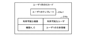
- FIG. 2 to 4 are diagrams showing a configuration example of the feature point information 24a and the management table 24b of the biometric information of the registrant in the IC card 2 issued for each individual user (registrant).
- FIG. 2 shows an example of the feature point information 24a and the management table 24b of the biometric information of the registrant in the IC card (IC card for the user 1) 2 issued to the user 1.
- FIG. 3 shows an example of the feature point information 24a and the management table 24b of the biometric information of the registrant in the IC card (IC card for the user 2) 2 issued to the user 2.
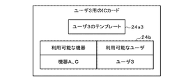
- FIG. 4 shows an example of the feature point information 24a and the management table 24b of the biometric information of the registrant in the IC card (IC card for the user 3) 2 issued to the user 3.
- the feature point information 24a of the biometric information of the registrant which is the dictionary data for biometric authentication of the user 1, and the use for which the user 1 has the usage authority.
- a management table 24b for storing information indicating the restricted device 1 is stored.
- the user 1 who can perform biometric authentication using the feature point information 24a of the biometric information of the registrant has the authority to use the device A and the device C.
- the data memory 24 of the IC card 2 contains the feature point information 24a of biometric information, which is the dictionary data for biometric authentication of the user 2, and the usage restriction device 1 to which the user 2 has the usage authority.
- a management table 24b for storing information indicating the above is stored. In the management table 24b shown in FIG. 3, it is shown that the user 2 who can perform biometric authentication using the feature point information 24a of the biometric information has the right to use the device B and the device C.
- the data memory 24 of the IC card 2 contains the feature point information 24a of biometric information, which is the dictionary data for biometric authentication of the user 3, and the usage restriction device 1 to which the user 3 has the usage authority.
- a management table 24b for storing information indicating the above is stored.
- the management table 24b shown in FIG. 3 it is shown that the user 3 who can perform biometric authentication using the feature point information 24a of the biometric information has the right to use the device A and the device C.
- the IC card 2 possessed by each user is provided with the feature point information 24a of the biometric information of the user who is the owner and the device that can be used by the user. Register the information to be shown.
- This makes it possible to provide an IC card 2 that can confirm not only biometric authentication for the registrant who is the owner but also the devices that can be used by the registrant (user).
- the feature point information 24a and the management table 24b of the registrant's biometric information as shown in FIGS.
- FIG. 5 to 7 are diagrams showing a configuration example of the feature point information 24a and the management table 24b of the registrant's biometric information in the IC card 2 issued for each use-restricted device.
- FIG. 5 shows an example of the feature point information 24a and the management table 24b of the registrant's biometric information in the IC card (IC card for the device A) 2 issued to the device A.
- FIG. 6 shows an example of the feature point information 24a and the management table 24b of the registrant's biometric information in the IC card (IC card for the device B) 2 issued to the device B.
- FIG. 7 shows an example of the feature point information 24a and the management table 24b of the registrant's biometric information in the IC card (IC card for the device C) 2 issued to the device C.
- the feature point information 24a1 of the biometric information of the user 1 who has the authority to use the device A and the feature point information 24a2 of the biometric information of the user 2 are stored in the data memory 24 of the device A.
- a management table 24b that stores information indicating a user who has usage authority is stored.
- the users who have the authority to use the device A are the user 1 of the feature point information 24a1 of the biometric information and the user 2 of the feature point information 24a2 of the biometric information.
- the data memory 24 of the IC card 2 stores information indicating the user who has the right to use the device B together with the feature point information 24a2 of the biometric information of the user 2 who has the right to use the device B.
- the management table 24b is stored. In the management table 24b shown in FIG. 6, it is shown that the user who has the authority to use the device B is the user 2 of the feature point information 24a2 of the biometric information.
- the data memory 24 of the IC card 2 contains the feature point information 24a1 of the biometric information of the user 1 who has the authority to use the device C, the feature point information 24a2 of the biometric information of the user 2, and the living body of the user 3.
- a management table 24b for storing information indicating a user who has the authority to use the device C is stored.
- the users who have the authority to use the device C are the user 1 of the feature point information 24a1 of the biometric information, the user 2 of the feature point information 24a2 of the biometric information, and the user of the feature point information 24a3 of the biometric information. It is shown to be 3.
- the IC card 2 issued (set) for each usage-restricted device contains the user who can use the usage-restricted device and the feature point information of the biometric information of each user. be registered.
- the feature point information 24a and the management table 24b of the registrant's biometric information as shown in FIGS. 5 to 7 are transferred to the IC card 2 for each device. By registering, it is possible to confirm the device used in the IC card 2 and biometric authentication of the user as described later.
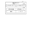
- FIG. 8 is a diagram showing a configuration example of the feature point information 24a and the management table 24b of the registrant's biometric information in the IC card 2 issued to one system.
- FIG. 8 shows an example of the feature point information 24a and the management table 24b of the registrant's biometric information in the IC card (IC card for master) 2 issued to the entire system having the three devices A, B, and C. Is shown.
- the data memory 24 of the IC card 2 is provided with feature point information 24a1, 24a2, 24a3 of biometric information for three people and information indicating users who have usage authority for each of the three devices.
- the management table 24b to be stored is stored.
- the feature point information 24a1, 24a2, and 24a3 of the biometric information shown in FIG. 8 are dictionary data for biometric authentication of the user 1, the user 2, and the user 3, respectively. Further, in the management table 24b shown in FIG. 8, the users who have the usage authority of the device A are the user 1 and the user 2, the users who have the usage authority of the device B are the user 2, and the users have the usage authority of the device C. It is shown that the users are user 1, user 2, and user 3.
- the IC card 2 issued (set) to the entire system including the plurality of usage-restricted devices has the user who can use the usage-restricted device and the feature point information of the biometric information of each user. And are registered.
- the feature point information 24a and the management table 24b of the registrant's biometric information as shown in FIG. 8 are transferred to the IC card 2.
- the IC card having the configurations shown in FIGS. 2 to 4 and the configurations shown in FIGS. 5 to 7 are provided.
- An IC card and an IC card having the configuration shown in FIG. 8 may be issued respectively.
- the IC card for each user is issued. Even if a problem occurs or the IC card for each user is lost, it is possible to realize an operation in which the restricted device can be used with the master IC card.
- FIG. 9 is a timing chart for explaining an operation example of the authentication system 10 according to the embodiment.
- a user who intends to use a certain usage restriction device 1 sets an IC card 2 for biometric (fingerprint) authentication in a reader / writer 15 of the usage restriction device 1.
- the usage restriction device 1 supplies electric power for operation to the IC card 2 set in the reader / writer 15 (ST10).
- the IC card 2 is activated (activated) by receiving electric power supplied from the reader / writer 15 via the communication interface 25 (ST11).
- the processor 21 of the IC card 2 When the processor 21 of the IC card 2 is activated by the electric power from the reader / writer 15, the initial response is transmitted to the reader / writer 15.
- the reader / writer 15 supplies electric power for operation to the set IC card 2 and receives an initial response from the IC card 2.
- the reader / writer 15 Upon receiving the initial response, the reader / writer 15 performs mutual authentication with the IC card 2 to establish a communication state.
- the processor 11 of the usage-restricted device 1 transmits the device ID as the identification information of the usage-restricted device 1 and authenticates the user on the IC card 2. Is sent (ST12).
- the processor 21 of the IC card 2 registers the feature point information of the biometric information of the person who has the usage authority of the usage-restricted device 1 indicated by the received device ID in the IC card 2. (ST13).
- the processor 21 refers to the management table 24b and confirms whether or not the biometric information of the person who has the usage authority for the usage-restricted device of the device ID is registered, so that the usage-restricted device 1 is concerned.
- the IC card 2 is used to determine whether or not the device can be used (ST14).
- the processor 21 when the biometric information of a person who has the authority to use the device of the received device ID is registered, the processor 21 is assumed to be a device that can be used by the usage restriction device 1 in which the IC card 2 is set. Further, when the biometric information of the person who has the authority to use the device of the received device ID is not registered, the processor 21 is assumed to be a device in which the usage restriction device 1 in which the IC card 2 is set cannot be used.
- the processor 21 uses the fact that the restricted device 1 is an unusable device. Respond to restriction device 1 (ST20). In this case, the usage-restricted device 1 in which the IC card 2 is set is in a state in which the processing unit 16 cannot execute the process in response to the response that the device cannot be used as described above.
- the processor 21 activates the fingerprint sensor 27 as a biosensor through the MPU 26, and the fingerprint sensor 27 Acquires a fingerprint image as biometric information of the user (ST15).
- the user assumes that the finger having the fingerprint used for authentication is placed at the reading position of the fingerprint sensor 27.
- the MPU 26 may detect that a finger is placed at the reading position of the fingerprint sensor 27 and read the fingerprint image by the fingerprint sensor 27.
- the processor 21 and the MPU 26 perform biometric (fingerprint) authentication using the acquired fingerprint image (ST16).
- the MPU 26 extracts feature point information from the fingerprint image acquired by the fingerprint sensor 27, and transmits the extracted feature point information to the processor 21.
- the processor 21 acquires the feature point information of the user's fingerprint image read by the fingerprint sensor 27 from the MPU 26.
- the processor 21 collates the feature point information of the acquired user's fingerprint image with the feature point information of the registrant's fingerprint image registered in the data memory 24.
- the processor 21 calculates the similarity between the feature point information of the fingerprint image of the user and the feature point information of the fingerprint image of the registrant, and the user is the registrant depending on whether or not the calculated similarity is equal to or higher than the threshold for authentication. It is determined whether or not it is.
- the processor 21 uses the restricted device 1 in which the user (that is, the registrant) matching the registrant is indicated by the device ID. It is determined whether or not the user has the right to use the user (ST17).
- the processor 21 uses the usage-restricted device 1 in which the user who puts his / her finger on the fingerprint sensor 27 is indicated by the device ID.
- the communication interface 25 responds to the reader / writer 15 of the usage restriction device 1 that the registrant who can use the user is authenticated (ST18).
- the processor 11 of the usage restriction device 1 When the IC card 2 receives a response that the user has been authenticated by the reader / writer 15, the processor 11 of the usage restriction device 1 permits the operation of the processing unit 16 and the processing requested by the user. Is in an executable state (ST19). In this case, the processor 11 of the usage restriction device 1 records in the memory 14 the history information indicating the usage content executed by the user together with the information indicating the user who is permitted to use the IC card 2 based on the authentication result (ST20). ..
- the processor 21 cannot confirm that the user has the usage authority, or , The fact that the usage-restricted device 1 is unavailable is used as a response to the usage-restricted device 1 (ST21).
- the processor 11 of the usage restriction device 1 When the IC card 2 receives a response that the user cannot be authenticated as a registrant or that the usage restriction device 1 is an unusable device, the processor 11 of the usage restriction device 1 is a processing unit. The operation of 16 is disabled, and the user cannot use the usage-restricted device 1 (ST22). In this case, the processor 11 of the usage restriction device 1 may record in the memory 14 the history information indicating that the use is disabled due to the result of the authentication in the IC card 2.
- the registrant registered in the IC card is the usage-restricted device. It is confirmed whether or not the user has the right to use the device, and whether or not the user is a registrant who has the right to use the restricted device is confirmed by biometric authentication acquired by the biometric sensor.
- the IC card can be prevented from being used by a person who does not have the usage authority, and the user has the usage authority by biometric authentication. It can be confirmed that the person has. As a result, the IC card can surely confirm the use of the device and prevent spoofing by biometric authentication, so that it is possible to surely use the device whose use is restricted by a person who has the authority to use the IC card.
- the IC card confirms the user's usage authority for the device and the registrant (patient or identification) for which the user has the usage authority. Operator) Performs biometric authentication to confirm the identity of the patient with biometric information.
- the IC card can be allowed to perform medical treatment by the restricted device when the biometric authentication with the person who has the authority to use the restricted device is successful, and the IC card can be associated with the registrant. It is possible to ensure that medical treatment is provided by the correct usage restriction device.
- the management table 24b of the IC card 2 stores information indicating the qualification possessed by the registrant and information indicating the qualification that the use of each usage-restricted device is permitted.
- an example of confirming whether or not the use-restricted device can be used based on the qualification possessed by the user will be described.
- the configurations other than the management table 24b can be realized by the same configurations as those in the above-described embodiment, detailed description thereof will be omitted.
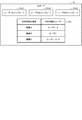
- FIG. 10 is a diagram showing a configuration example of the feature point information 24a and the management table 24b of the biometric information of the registrant in the IC card 2 when confirming the usage authority of the usage-restricted device based on the qualification information.
- the data memory 24 of the IC card 2 includes a management table 24b including feature point information 24a1, 24a2, 24a3 of biometric information for three people, and a first table 24b1 and a second table 24b2. Is memorized.
- the first table 24b1 stores information indicating qualifications required when using each usage-restricted device (devices A, B, C).
- the second table 24b2 stores information indicating the qualifications of each registrant (users 1, 2, 3).
- the processor 21 of the IC card 2 shown in FIG. 10 can identify that the user 1 and the user 3 have the right to use the device A by referring to the management table 24b.
- the device B can determine from the first table 24b1 that the qualification required for use is ⁇ , and can determine from the second table 24b2 that the user having the qualification ⁇ is the user 2. That is, the processor 21 of the IC card 2 shown in FIG. 10 can identify that the user 2 has the right to use the device B by referring to the management table 24b.
- the processor 21 of the IC card 2 shown in FIG. 10 can identify that the users 1, 2, and 3 have the right to use the device C by referring to the management table 24b.
- the authentication system according to the modified example can realize the same processing in the same flow as the processing shown in FIG. 9 described above.
- the processing of ST13 in FIG. 9 is a device that can be used by the usage restriction device in which the IC card is set by referring to the information registered in the management table 24b as shown in FIG. It should be confirmed based on the qualification of the registrant.
- the processing of ST13 in FIG. 9 is a device that can be used by the usage restriction device in which the IC card is set by referring to the information registered in the management table 24b as shown in FIG. It should be confirmed based on the qualification of the registrant.
- an IC card as a portable authentication device that can confirm the users who can use each device based on the qualifications of each registrant. Can be provided.
Abstract
According to an embodiment of the present invention, an authentication device is provided with a sensor, a communication interface, a memory, and a processor. The sensor acquires biometric information. The communication interface communicates with an appliance. The memory stores feature point information, used for biometric authentication, relating to the biometric information of a registrant, and management information indicating an appliance that the registrant has authority to use. The processor authenticates whether the user from which the sensor has acquired the biometric information is a registrant having authority to use the appliance with which communication is being performed by means of the communication interface, and transmits the authentication result to the appliance with which communication is being performed by means of the communication interface.
Description
本発明の実施形態は、携帯可能な認証デバイス、ICカードおよび認証システムに関する。
Embodiments of the present invention relate to a portable authentication device, an IC card and an authentication system.
従来、医療機器などの利用者を制限する必要がある機器を運用するためのシステムとして、予め設定(指定)された人物または有資格者だけに機器(以下、利用制限機器と称する)の操作を許可する認証システムがある。従来の認証システムでは、利用制限機器または利用制限機器に接続したサーバなどの上位装置に登録された人物であることを確認できた場合に、利用制限機器の利用を許可する。
Conventionally, as a system for operating a device that needs to restrict users such as medical devices, the operation of the device (hereinafter referred to as a usage-restricted device) is performed only by a preset (designated) person or a qualified person. There is an authentication system to allow. In the conventional authentication system, when it is confirmed that the person is registered in a higher-level device such as a usage-restricted device or a server connected to the usage-restricted device, the use of the usage-restricted device is permitted.
しかしながら、利用制限機器でユーザ認証を行う場合には、ユーザ認証を行うためのハードウエアを利用制限機器に設けなければならない。また、生体認証などでユーザ認証を行う場合、利用制限機器または利用制限機器の上位装置が、全ての登録者の生体情報などをセキュアに管理しなければならないという問題がある。
However, when user authentication is performed on a usage-restricted device, the hardware for user authentication must be provided on the usage-restricted device. Further, when user authentication is performed by biometric authentication or the like, there is a problem that the usage-restricted device or the host device of the usage-restricted device must securely manage the biometric information of all the registrants.
一方、指紋認証を行うICカードが実用化されている。ICカードでは、セキュアに生体情報を管理でき、セキュリティ性が高い生体認証を実現している。しかしながら、従来のICカードは、ユーザの生体情報と登録者との生体認証の結果を出力するだけであり、登録者が機器本体の利用権限を持っているか否かを確認することできない。
On the other hand, IC cards that perform fingerprint authentication have been put into practical use. With IC cards, biometric information can be managed securely, and biometric authentication with high security is realized. However, the conventional IC card only outputs the biometric information of the user and the result of biometric authentication with the registrant, and cannot confirm whether or not the registrant has the authority to use the device itself.
上記の課題を解決するため、機器の利用権限を有する人物であるかを生体認証で認証した結果を前記機器へ供給できる携帯可能な認証デバイス、ICカードおよび認証システムを提供する。
In order to solve the above problems, we provide a portable authentication device, an IC card and an authentication system that can supply the result of biometric authentication of a person who has the authority to use the device to the device.
実施形態によれば、認証デバイスは、センサと通信インターフェースとメモリとプロセッサとを備える。センサは、生体情報を取得する。通信インターフェースは、機器と通信する。メモリは、生体認証に用いる登録者の生体情報の特徴点情報(テンプレート)と登録者が利用権限を有する機器を示す管理情報とを記憶する。プロセッサは、センサが生体情報を取得したユーザが前記通信インターフェースにより通信する機器の利用権限を有する登録者であるかを認証し、認証の結果を通信インターフェースにより通信する機器へ送信する。
According to the embodiment, the authentication device includes a sensor, a communication interface, a memory, and a processor. The sensor acquires biometric information. The communication interface communicates with the device. The memory stores feature point information (template) of the registrant's biometric information used for biometric authentication and management information indicating a device for which the registrant has usage authority. The processor authenticates whether the user who has acquired the biometric information is a registrant who has the authority to use the device communicating by the communication interface, and transmits the authentication result to the device communicating by the communication interface.
以下、実施形態について、図面を参照して説明する。
実施形態に係るICカードなどの携帯可能電子装置は、ユーザから取得する生体情報を用いてセキュアに人物の認証処理を行う携帯可能な認証デバイスである。本実施形態において、ICカードは、人物の指紋の画像(指紋画像)を取得する生体センサとしての指紋センサを具備し、指紋センサで取得する指紋画像を用いて認証処理を行う。 Hereinafter, embodiments will be described with reference to the drawings.
The portable electronic device such as an IC card according to the embodiment is a portable authentication device that securely performs a person authentication process using biometric information acquired from a user. In the present embodiment, the IC card includes a fingerprint sensor as a biological sensor that acquires an image (fingerprint image) of a person's fingerprint, and performs an authentication process using the fingerprint image acquired by the fingerprint sensor.
図1は、実施形態に係るICカード2を含む認証システム10の構成例を示す。
図1が示すように、認証システム10は、ICカード2と複数種類の利用制限機器1(1A、1B、1C、…)とを含むシステムである。利用制限機器1は、特定の人物に対して利用が許可される機器である。例えば、利用制限機器1は、予め設定した人物に対して利用が許可されるものであっても良いし、特定の資格を有する人物に対して利用が許可されるものであっても良い。 FIG. 1 shows a configuration example of theauthentication system 10 including the IC card 2 according to the embodiment.
As shown in FIG. 1, theauthentication system 10 is a system including an IC card 2 and a plurality of types of restricted use devices 1 (1A, 1B, 1C, ...). The usage restriction device 1 is a device that is permitted to be used by a specific person. For example, the usage restriction device 1 may be one that is permitted to be used by a preset person, or may be one that is permitted to be used by a person having a specific qualification.
図1が示すように、認証システム10は、ICカード2と複数種類の利用制限機器1(1A、1B、1C、…)とを含むシステムである。利用制限機器1は、特定の人物に対して利用が許可される機器である。例えば、利用制限機器1は、予め設定した人物に対して利用が許可されるものであっても良いし、特定の資格を有する人物に対して利用が許可されるものであっても良い。 FIG. 1 shows a configuration example of the
As shown in FIG. 1, the
利用制限機器1は、携帯可能な認証デバイスとしてのICカード2と通信する機能を有する。利用制限機器1は、ICカード2によって自機の利用が許可されている人物であることが認証された場合、当該人物による利用が可能となる装置である。利用制限機器1は、予め設定した人物が操作可能となる医療機器などであっても良いし、有資格者である場合に操作可能となる装置であっても良い。
図1に示す構成例において、利用制限機器1は、プロセッサ11、ROM12、RAM13、データメモリ14、リーダライタ15および処理部16を有する。
プロセッサ11は、各部の制御および各種の処理などを実行する。プロセッサ11は、例えば、CPU(central processing unit)である。プロセッサ11は、ROM11またはデータメモリ14に記憶されたプログラムを実行することにより各部の制御および各種の処理を実現する。 The usage restriction device 1 has a function of communicating with theIC card 2 as a portable authentication device. The usage restriction device 1 is a device that can be used by the person when it is authenticated by the IC card 2 that the person is permitted to use the own device. The usage restriction device 1 may be a medical device or the like that can be operated by a preset person, or may be a device that can be operated by a qualified person.
In the configuration example shown in FIG. 1, the usage restriction device 1 includes a processor 11, aROM 12, a RAM 13, a data memory 14, a reader / writer 15, and a processing unit 16.
The processor 11 controls each part and executes various processes. The processor 11 is, for example, a CPU (central processing unit). The processor 11 realizes control of each part and various processes by executing a program stored in the ROM 11 or thedata memory 14.
図1に示す構成例において、利用制限機器1は、プロセッサ11、ROM12、RAM13、データメモリ14、リーダライタ15および処理部16を有する。
プロセッサ11は、各部の制御および各種の処理などを実行する。プロセッサ11は、例えば、CPU(central processing unit)である。プロセッサ11は、ROM11またはデータメモリ14に記憶されたプログラムを実行することにより各部の制御および各種の処理を実現する。 The usage restriction device 1 has a function of communicating with the
In the configuration example shown in FIG. 1, the usage restriction device 1 includes a processor 11, a
The processor 11 controls each part and executes various processes. The processor 11 is, for example, a CPU (central processing unit). The processor 11 realizes control of each part and various processes by executing a program stored in the ROM 11 or the
ROM12は、書き換え不可のデータを保存する不揮発性メモリである。ROM12は、プログラムまたは制御データなどを記憶する。RAM13は、データを一時的に記憶する揮発性メモリである。
データメモリ14は、書き換え可能な不揮発性のメモリである。データメモリ14は、HDD(ハードディスクドライブデータ)あるいはSSD(ソリッドステートドライブ)などで実現される。 TheROM 12 is a non-volatile memory for storing non-rewritable data. The ROM 12 stores a program, control data, or the like. The RAM 13 is a volatile memory that temporarily stores data.
Thedata memory 14 is a rewritable non-volatile memory. The data memory 14 is realized by an HDD (hard disk drive data), an SSD (solid state drive), or the like.
データメモリ14は、書き換え可能な不揮発性のメモリである。データメモリ14は、HDD(ハードディスクドライブデータ)あるいはSSD(ソリッドステートドライブ)などで実現される。 The
The
リーダライタ15は、ICカード2と通信接続するためのインターフェースである。リーダライタ15は、ICカード2に対して電源供給、クロック供給、リセット制御、データの送受信が行う。リーダライタ15は、ICカード2の通信方式に応じたインターフェースにより構成される。
The reader / writer 15 is an interface for communicating with the IC card 2. The reader / writer 15 supplies power to the IC card 2, supplies clocks, resets, and sends / receives data. The reader / writer 15 is configured by an interface corresponding to the communication method of the IC card 2.
例えば、ICカード2が接触型のICカードである場合、リーダライタ15は、ICカード2のコンタクト部と物理的かつ電気的に接続するための接触部などにより構成される。また、ICカード2が非接触型のICカードである場合、リーダライタ15は、ICカード2との無線通信を行うためのアンテナ及び通信制御部などにより構成される。
For example, when the IC card 2 is a contact type IC card, the reader / writer 15 is composed of a contact portion for physically and electrically connecting to the contact portion of the IC card 2. When the IC card 2 is a non-contact type IC card, the reader / writer 15 is composed of an antenna for wireless communication with the IC card 2, a communication control unit, and the like.
処理部16は、ICカード2によって利用が許可された場合に処理を実行するものである。例えば、処理部16は、ICカード2において予め設定された人物であることが認証された場合に処理を実行するものであっても良いし、ICカード2において所定の資格を有する人物であることが認証された場合に処理を実行するものであっても良い。具体例として、処理部16は、医療行為を実行または補助するための処理機構を含むものであっても良いし、運転(操作)免許を有する人物(有資格者)の操作に応じて駆動する駆動機構を含むものであっても良い。
The processing unit 16 executes processing when the use is permitted by the IC card 2. For example, the processing unit 16 may execute processing when it is authenticated that the person is a preset person in the IC card 2, or is a person having a predetermined qualification in the IC card 2. May be executed when is authenticated. As a specific example, the processing unit 16 may include a processing mechanism for executing or assisting a medical practice, or is driven according to the operation of a person (qualified person) having a driving (operation) license. It may include a drive mechanism.
次に、ICカード2の構成について説明する。
ICカード2は、生体情報による認証(生体認証)を実行する機能を有する携帯可能な認証デバイスである。実施形態に係る認証システムにおいて、ICカード2は、利用制限機器1のリーダライタ15から供給される電力によって動作し、リーダライタ15からのコマンドに従って処理を実行する。また、ICカード2は、リーダライタ15からのコマンドに対する処理結果を示すレスポンスをリーダライタ15へ供給する。 Next, the configuration of theIC card 2 will be described.
TheIC card 2 is a portable authentication device having a function of performing authentication by biometric information (biometric authentication). In the authentication system according to the embodiment, the IC card 2 operates by the electric power supplied from the reader / writer 15 of the usage restriction device 1, and executes the process according to the command from the reader / writer 15. Further, the IC card 2 supplies the reader / writer 15 with a response indicating the processing result for the command from the reader / writer 15.
ICカード2は、生体情報による認証(生体認証)を実行する機能を有する携帯可能な認証デバイスである。実施形態に係る認証システムにおいて、ICカード2は、利用制限機器1のリーダライタ15から供給される電力によって動作し、リーダライタ15からのコマンドに従って処理を実行する。また、ICカード2は、リーダライタ15からのコマンドに対する処理結果を示すレスポンスをリーダライタ15へ供給する。 Next, the configuration of the
The
図1に示す構成例において、ICカード2は、プラスチックなどで形成されたカード状の本体Cを有する。ICカード2は、本体C内にモジュールMおよびモジュールMに接続された生体センサ(指紋センサ)27を内蔵する。モジュールMは、ICチップCa、通信インターフェース25およびMPU26が接続された状態で一体的に形成され、ICカード2の本体C内に埋設される。
In the configuration example shown in FIG. 1, the IC card 2 has a card-shaped main body C made of plastic or the like. The IC card 2 has a module M and a biosensor (fingerprint sensor) 27 connected to the module M built in the main body C. The module M is integrally formed with the IC chip Ca, the communication interface 25, and the MPU 26 connected to each other, and is embedded in the main body C of the IC card 2.
さらに、ICチップCaは、プロセッサ21、ROM22、RAM23及びデータメモリ24などを備える。プロセッサ21は、データバスなどを介してROM22、RAM23、データメモリ24、通信インターフェース25およびMPU26に接続する。MPU26は、データバスなどを介して生体センサ27に接続する。
なお、ICカード2は、図1が示すような構成の他に必要に応じた構成を具備したり、ICカード2から特定の構成が除外されたりしてもよい。 Further, the IC chip Ca includes aprocessor 21, a ROM 22, a RAM 23, a data memory 24, and the like. The processor 21 connects to the ROM 22, the RAM 23, the data memory 24, the communication interface 25, and the MPU 26 via a data bus or the like. The MPU 26 is connected to the biosensor 27 via a data bus or the like.
TheIC card 2 may have a configuration as required in addition to the configuration shown in FIG. 1, or a specific configuration may be excluded from the IC card 2.
なお、ICカード2は、図1が示すような構成の他に必要に応じた構成を具備したり、ICカード2から特定の構成が除外されたりしてもよい。 Further, the IC chip Ca includes a
The
プロセッサ21は、ICカード2全体の制御を司る制御部として機能する。プロセッサ21は、ROM22またはデータメモリ24に記憶される制御プログラム及び制御データに基づいて種々の処理を行う。例えば、プロセッサ21は、ROM22に記憶されているプログラムを実行することにより、ICカード2の動作制御またはICカード2の運用形態に応じた種々の処理を行う。
The processor 21 functions as a control unit that controls the entire IC card 2. The processor 21 performs various processes based on the control program and the control data stored in the ROM 22 or the data memory 24. For example, the processor 21 executes various processes according to the operation control of the IC card 2 or the operation mode of the IC card 2 by executing the program stored in the ROM 22.
例えば、プロセッサ21は、プログラムを実行することにより、ICカード2内の各部の制御及び情報処理を実現するプロセッサであればよい。
なお、プロセッサ21がプログラムを実行することにより実現する各種の機能のうちの一部は、ハードウエア回路により実現されるものであっても良い。この場合、プロセッサ21は、ハードウエア回路により実行される機能を制御する。 For example, theprocessor 21 may be a processor that realizes control and information processing of each part in the IC card 2 by executing a program.
It should be noted that some of the various functions realized by theprocessor 21 executing the program may be realized by the hardware circuit. In this case, the processor 21 controls the functions performed by the hardware circuits.
なお、プロセッサ21がプログラムを実行することにより実現する各種の機能のうちの一部は、ハードウエア回路により実現されるものであっても良い。この場合、プロセッサ21は、ハードウエア回路により実行される機能を制御する。 For example, the
It should be noted that some of the various functions realized by the
ROM22は、予め制御用のプログラム及び制御データなどを記憶する不揮発性のメモリである。ROM22は、製造段階で制御プログラム及び制御データなどを記憶した状態でICカード2に組み込まれる。例えば、ROM22に記憶される制御プログラム及び制御データは、予めICカード2の仕様などに応じて組み込まれる。
ROM 22 is a non-volatile memory that stores control programs, control data, and the like in advance. The ROM 22 is incorporated in the IC card 2 in a state where the control program, control data, and the like are stored in the manufacturing stage. For example, the control program and control data stored in the ROM 22 are incorporated in advance according to the specifications of the IC card 2.
RAM23は、揮発性のメモリである。RAM23は、プロセッサ21の処理中のデータなどを一時的に格納する。例えば、RAM23は、計算用バッファ、受信用バッファ及び送信用バッファとして機能する。計算用バッファは、プロセッサ21が実行する種々の演算処理の結果などを一時的に保持する。受信用バッファは、通信インターフェース25を介してリーダライタ15から受信するコマンドデータなどを保持する。送信用バッファは、通信インターフェース25を介してリーダライタ15へ送信するメッセージ(レスポンスデータ)などを保持する。
RAM 23 is a volatile memory. The RAM 23 temporarily stores data and the like being processed by the processor 21. For example, the RAM 23 functions as a calculation buffer, a reception buffer, and a transmission buffer. The calculation buffer temporarily holds the results of various arithmetic processes executed by the processor 21. The reception buffer holds command data and the like received from the reader / writer 15 via the communication interface 25. The transmission buffer holds a message (response data) or the like to be transmitted to the reader / writer 15 via the communication interface 25.
データメモリ24は、フラッシュROMなどのデータの書き込み及び書換えが可能な不揮発性のメモリにより構成される。データメモリ24は、ICカード2の運用用途に応じて制御プログラム、アプリケーション及び種々のデータを格納する。例えば、データメモリ24では、プログラムファイル及びデータファイルなどが作成される。作成された各ファイルは、制御プログラム及び種々のデータなどが書き込まれる。
The data memory 24 is composed of a non-volatile memory such as a flash ROM capable of writing and rewriting data. The data memory 24 stores a control program, an application, and various data according to the operational use of the IC card 2. For example, in the data memory 24, a program file, a data file, and the like are created. A control program and various data are written in each created file.
また、データメモリ24は、生体(指紋)認証の辞書データとして登録者の生体情報から得られる生体情報の特徴点情報(テンプレート)24aを記憶する。生体情報の特徴点情報24aは、例えば、登録者の生体情報から抽出される特徴量としての特徴点情報である。データメモリ24には、登録者ごとの生体情報の特徴点情報24aが記憶される。ICカード2は、特定の1人の登録者に対する生体情報の特徴点情報24aを登録するものであっても良いし、複数の登録者に対応する複数の生体情報の特徴点情報24a(24a1、24a2、42a3、…)を登録するようにしても良い。
Further, the data memory 24 stores the feature point information (template) 24a of the biometric information obtained from the biometric information of the registrant as the dictionary data of the biometric (fingerprint) authentication. The feature point information 24a of the biological information is, for example, feature point information as a feature amount extracted from the biological information of the registrant. The data memory 24 stores feature point information 24a of biometric information for each registrant. The IC card 2 may register the feature point information 24a of biometric information for one specific registrant, or the feature point information 24a (24a1, 24a1) of a plurality of biometric information corresponding to a plurality of registrants. 24a2, 42a3, ...) may be registered.
また、データメモリ24は、利用者(登録者)が使用できる利用制限機器1を示す管理テーブル24bを有する。管理テーブル24bは、生体情報の特徴点情報24aが登録される登録者に対して利用が許可されている利用制限機器との関係を示す情報が記憶される。管理テーブル24bは、登録者と利用制限機器の利用権限との関係を示すデータを格納するものであれば良い。例えば、管理テーブル24bは、登録者ごとに利用可能な利用制限機器を示す情報を格納しても良いし、利用制限機器ごとに利用権限を有する登録者を示す情報を格納しても良いし、複数の登録者と複数の利用制限機器の利用権限との対応づけを示す情報を格納しても良い。また、管理テーブル24bは、登録者が有する資格と各種の資格に対する利用制限機器の利用権限とを対応づけて記憶するようにしても良い。
Further, the data memory 24 has a management table 24b showing the usage restriction device 1 that can be used by the user (registrant). The management table 24b stores information indicating the relationship with the usage-restricted device that is permitted to be used by the registrant in which the feature point information 24a of the biological information is registered. The management table 24b may store data indicating the relationship between the registrant and the usage authority of the restricted use device. For example, the management table 24b may store information indicating a usage-restricted device that can be used for each registrant, or may store information indicating a registrant who has usage authority for each usage-restricted device. Information indicating the association between a plurality of registrants and the usage authority of a plurality of restricted devices may be stored. Further, the management table 24b may store the qualifications of the registrant and the usage authority of the usage-restricted device for various qualifications in association with each other.
通信インターフェース25は、リーダライタ15とデータを送受信するためのインターフェースである。すなわち、通信インターフェース25は、リーダライタ15を通じて利用制限機器1とデータを送受信するためのインターフェースである。
The communication interface 25 is an interface for transmitting and receiving data to and from the reader / writer 15. That is, the communication interface 25 is an interface for transmitting / receiving data to / from the restricted use device 1 through the reader / writer 15.
ICカード2が接触型のICカードとして実現される場合、通信インターフェース25は、リーダライタ15と物理的かつ電気的に接触して信号の送受信を行うための通信制御部とコンタクト部とにより構成される。例えば、ICカード2は、コンタクト部を介してリーダライタ15からの動作電源及び動作クロックの供給を受けて活性化される。
When the IC card 2 is realized as a contact type IC card, the communication interface 25 is composed of a communication control unit and a contact unit for physically and electrically contacting the reader / writer 15 to transmit and receive signals. NS. For example, the IC card 2 is activated by receiving an operating power supply and an operating clock from the reader / writer 15 via the contact portion.
ICカード2が非接触型のICカードとしての実現される場合、通信インターフェース25は、リーダライタ15との無線通信を行うための変復調回路などの通信制御部とアンテナとにより構成される。例えば、ICカード2は、アンテナ及び変復調回路などを介してリーダライタ15からの電波を受信する。ICカード2は、その電波から図示しない電源部により動作電源及び動作クロックを生成して活性化する。
When the IC card 2 is realized as a non-contact type IC card, the communication interface 25 is composed of a communication control unit such as a modulation / demodulation circuit for performing wireless communication with the reader / writer 15 and an antenna. For example, the IC card 2 receives radio waves from the reader / writer 15 via an antenna, a modulation / demodulation circuit, and the like. The IC card 2 is activated by generating an operating power supply and an operating clock from the radio wave by a power supply unit (not shown).
生体センサ27は、操作者の生体情報を取得する。生体センサ27は、例えば、指紋センサである。生体センサ27としての指紋センサは、操作者の指から指紋画像を取得する。生体センサ27としての指紋センサは、CCDセンサなどを備える。また、指紋センサ27は、電気容量の変化を検出するセンサなどを備えるものであってもよい。指紋センサ27は、指紋画像をMPU26に送信する。
以下、本実施形態では、一例としてICカード2が接触型のICカードである場合を想定して説明するものとするが、ICカード2が非接触型のICカードであっても同様に実現可能なものである。また、生体センサ27は、指紋センサであるものとし、ICカード2が利用制限機器1のリーダライタ15にセットされた状態でユーザの指が指紋センサの読取位置に置けるようにするものとする。 Thebiological sensor 27 acquires the biological information of the operator. The biosensor 27 is, for example, a fingerprint sensor. The fingerprint sensor as the biosensor 27 acquires a fingerprint image from the operator's finger. The fingerprint sensor as the biological sensor 27 includes a CCD sensor and the like. Further, the fingerprint sensor 27 may be provided with a sensor or the like that detects a change in the electric capacity. The fingerprint sensor 27 transmits a fingerprint image to the MPU 26.
Hereinafter, in the present embodiment, the case where theIC card 2 is a contact type IC card will be described as an example, but the same can be realized even if the IC card 2 is a non-contact type IC card. It is a thing. Further, the biosensor 27 is assumed to be a fingerprint sensor, and the user's finger can be placed at the reading position of the fingerprint sensor in a state where the IC card 2 is set in the reader / writer 15 of the usage restriction device 1.
以下、本実施形態では、一例としてICカード2が接触型のICカードである場合を想定して説明するものとするが、ICカード2が非接触型のICカードであっても同様に実現可能なものである。また、生体センサ27は、指紋センサであるものとし、ICカード2が利用制限機器1のリーダライタ15にセットされた状態でユーザの指が指紋センサの読取位置に置けるようにするものとする。 The
Hereinafter, in the present embodiment, the case where the
MPU26(Micro Processing Unit)は、指紋センサ27からの指紋画像を処理する。MPU26は、プロセッサ、RAMおよびROMなどを含む構成を有する。本実施形態で説明するMPU26が実現する処理は、ICチップCa内のプロセッサ21がROM22およびRAM23などを用いて実現できるものである。このため、以下の説明するMPU26の実行する処理は、プロセッサ21が実行するようにしても良い。
The MPU 26 (Micro Processing Unit) processes the fingerprint image from the fingerprint sensor 27. The MPU 26 has a configuration including a processor, RAM, ROM, and the like. The process realized by the MPU 26 described in the present embodiment can be realized by the processor 21 in the IC chip Ca using the ROM 22, the RAM 23, and the like. Therefore, the process executed by the MPU 26 described below may be executed by the processor 21.
MPU26は、指紋センサ27からの指紋画像から特徴点情報(特徴点の座標及び特徴量など示す情報)を抽出する。MPU26は、抽出した特徴点情報をプロセッサ21に送信する。上述したような指紋センサ27が取得する指紋画像から特徴点情報を抽出する処理は、プロセッサ21が実施するようにしても良い。
The MPU 26 extracts feature point information (information indicating the coordinates of the feature points and the feature amount) from the fingerprint image from the fingerprint sensor 27. The MPU 26 transmits the extracted feature point information to the processor 21. The processor 21 may perform the process of extracting the feature point information from the fingerprint image acquired by the fingerprint sensor 27 as described above.
プロセッサ21は、MPU26から送信される指紋センサ27で取得した指紋画像から抽出した特徴点情報とデータメモリ24などに登録されている指紋画像の特徴点情報とを照合する。例えば、プロセッサ21は、所定のアルゴリズムに従って、指紋画像同士の類似度として、指紋センサ27で取得した指紋画像から抽出した特徴点情報と登録されている指紋画像の特徴点情報との類似度を算出する。ここで、類似度は、高いほど指紋画像同士の類似性が高いことを示す指標である。
プロセッサ21は、データメモリ24などに登録されている指紋画像の特徴点情報を読み込んで保持する。プロセッサ21は、MPU26から送られる特徴点情報とプロセッサ21内に保持した特徴点情報とを照合して両者の類似度を算出する。
類似度を算出すると、プロセッサ21は、照合処理(認証処理)として、算出した類似度と認証用の閾値とを比較することにより認証の成否を判定する。例えば、プロセッサ21は、算出した類似度が認証用の閾値以上であれば同一人物である(認証成功)とし、類似度が認証用の閾値未満であれば同一人物と認めない(認証失敗)とすることにより認証処理の結果を得る。 Theprocessor 21 collates the feature point information extracted from the fingerprint image acquired by the fingerprint sensor 27 transmitted from the MPU 26 with the feature point information of the fingerprint image registered in the data memory 24 or the like. For example, the processor 21 calculates the similarity between the feature point information extracted from the fingerprint image acquired by the fingerprint sensor 27 and the feature point information of the registered fingerprint image as the similarity between the fingerprint images according to a predetermined algorithm. do. Here, the degree of similarity is an index indicating that the higher the degree of similarity, the higher the similarity between fingerprint images.
Theprocessor 21 reads and holds the feature point information of the fingerprint image registered in the data memory 24 or the like. The processor 21 collates the feature point information sent from the MPU 26 with the feature point information held in the processor 21 to calculate the similarity between the two.
When the similarity is calculated, theprocessor 21 determines the success or failure of the authentication by comparing the calculated similarity with the threshold value for authentication as a collation process (authentication process). For example, if the calculated similarity is equal to or higher than the authentication threshold value, the processor 21 is regarded as the same person (authentication success), and if the similarity degree is less than the authentication threshold value, it is not recognized as the same person (authentication failure). By doing so, the result of the authentication process is obtained.
プロセッサ21は、データメモリ24などに登録されている指紋画像の特徴点情報を読み込んで保持する。プロセッサ21は、MPU26から送られる特徴点情報とプロセッサ21内に保持した特徴点情報とを照合して両者の類似度を算出する。
類似度を算出すると、プロセッサ21は、照合処理(認証処理)として、算出した類似度と認証用の閾値とを比較することにより認証の成否を判定する。例えば、プロセッサ21は、算出した類似度が認証用の閾値以上であれば同一人物である(認証成功)とし、類似度が認証用の閾値未満であれば同一人物と認めない(認証失敗)とすることにより認証処理の結果を得る。 The
The
When the similarity is calculated, the
なお、指紋センサ27が取得した指紋画像と登録されている指紋画像との照合処理は、MPU26が実施しても良い。例えば、MPU26は、照合処理によって指紋センサ27で取得した指紋画像と登録されている指紋画像と類似度を算出し、算出した類似度をプロセッサ21に送信するようにしても良い。また、MPU26は、算出した類似度と認証用の閾値とを比較することにより認証の成否をプロセッサ21に送信するようにしてもよい。
The MPU 26 may perform the collation process between the fingerprint image acquired by the fingerprint sensor 27 and the registered fingerprint image. For example, the MPU 26 may calculate the similarity between the fingerprint image acquired by the fingerprint sensor 27 and the registered fingerprint image by the collation process, and transmit the calculated similarity to the processor 21. Further, the MPU 26 may transmit the success or failure of the authentication to the processor 21 by comparing the calculated similarity with the threshold value for the authentication.
なお、ICカード2は、プロセッサ21からの制御に従って種々の情報を表示する表示部を具備するものであっても良い。例えば、表示部は、プロセッサ21からの制御に従って点灯するライト(例えば、LED(Light Emitting Diode)ライト)などであってもよい。
The IC card 2 may be provided with a display unit that displays various information according to the control from the processor 21. For example, the display unit may be a light (for example, an LED (Light Emitting Diode) light) that lights up according to the control from the processor 21.
次に、実施形態に係る携帯可能な認証デバイスとしてのICカード2が記憶する情報について説明する。
上述した構成例によれば、ICカード2は、データメモリ24において、登録者ごとの生体情報の特徴点情報24aと管理テーブル24bと記憶する。上述したように、ICカード2は、1人の登録者の生体情報の特徴点情報24aを登録するようにしても良いし、複数の登録者に対する生体情報の特徴点情報24a1、24a2、…を登録するようにしても良い。また、管理テーブル24bは、登録者と利用権限を有する利用制限機器との関係を示す情報を記憶するものであれば良い。 Next, the information stored in theIC card 2 as the portable authentication device according to the embodiment will be described.
According to the configuration example described above, theIC card 2 stores the feature point information 24a and the management table 24b of the biometric information for each registrant in the data memory 24. As described above, the IC card 2 may register the feature point information 24a of the biometric information of one registrant, or may register the feature point information 24a1, 24a2, ... Of the biometric information for a plurality of registrants. You may try to register. Further, the management table 24b may store information indicating the relationship between the registrant and the usage-restricted device having the usage authority.
上述した構成例によれば、ICカード2は、データメモリ24において、登録者ごとの生体情報の特徴点情報24aと管理テーブル24bと記憶する。上述したように、ICカード2は、1人の登録者の生体情報の特徴点情報24aを登録するようにしても良いし、複数の登録者に対する生体情報の特徴点情報24a1、24a2、…を登録するようにしても良い。また、管理テーブル24bは、登録者と利用権限を有する利用制限機器との関係を示す情報を記憶するものであれば良い。 Next, the information stored in the
According to the configuration example described above, the
以下、実施形態に係る携帯可能な認証デバイスとしてのICカード2に登録する登録者の生体情報の特徴点情報24aと管理テーブル24bとの構成例について説明する。ここでは、具体例として、3人の登録者(ユーザ1、ユーザ2、ユーザ3)と3つの利用制限機器(機器A、機器B、機器C)とがある場合を想定して説明するものとする。
Hereinafter, a configuration example of the feature point information 24a and the management table 24b of the biometric information of the registrant registered in the IC card 2 as the portable authentication device according to the embodiment will be described. Here, as a specific example, it is assumed that there are three registrants (user 1, user 2, user 3) and three usage-restricted devices (device A, device B, device C). do.
図2乃至図4は、個々のユーザ(登録者)ごとに発行するICカード2における登録者の生体情報の特徴点情報24aと管理テーブル24bとの構成例を示す図である。
図2は、ユーザ1に対して発行されるICカード(ユーザ1用のICカード)2における登録者の生体情報の特徴点情報24aと管理テーブル24bとの例を示す。図3は、ユーザ2に対して発行されるICカード(ユーザ2用のICカード)2における登録者の生体情報の特徴点情報24aと管理テーブル24bとの例を示す。図4は、ユーザ3に対して発行されるICカード(ユーザ3用のICカード)2における登録者の生体情報の特徴点情報24aと管理テーブル24bとの例を示す。 2 to 4 are diagrams showing a configuration example of thefeature point information 24a and the management table 24b of the biometric information of the registrant in the IC card 2 issued for each individual user (registrant).
FIG. 2 shows an example of thefeature point information 24a and the management table 24b of the biometric information of the registrant in the IC card (IC card for the user 1) 2 issued to the user 1. FIG. 3 shows an example of the feature point information 24a and the management table 24b of the biometric information of the registrant in the IC card (IC card for the user 2) 2 issued to the user 2. FIG. 4 shows an example of the feature point information 24a and the management table 24b of the biometric information of the registrant in the IC card (IC card for the user 3) 2 issued to the user 3.
図2は、ユーザ1に対して発行されるICカード(ユーザ1用のICカード)2における登録者の生体情報の特徴点情報24aと管理テーブル24bとの例を示す。図3は、ユーザ2に対して発行されるICカード(ユーザ2用のICカード)2における登録者の生体情報の特徴点情報24aと管理テーブル24bとの例を示す。図4は、ユーザ3に対して発行されるICカード(ユーザ3用のICカード)2における登録者の生体情報の特徴点情報24aと管理テーブル24bとの例を示す。 2 to 4 are diagrams showing a configuration example of the
FIG. 2 shows an example of the
図2に示す例において、ICカード2のデータメモリ24には、ユーザ1の生体認証用の辞書データである登録者の生体情報の特徴点情報24aとユーザ1が利用権限を有している利用制限機器1を示す情報を格納する管理テーブル24bとが記憶される。図2に示す管理テーブル24bでは、登録者の生体情報の特徴点情報24aを用いて生体認証が可能なユーザ1が機器Aと機器Cとの利用権限を有することが示される。
In the example shown in FIG. 2, in the data memory 24 of the IC card 2, the feature point information 24a of the biometric information of the registrant, which is the dictionary data for biometric authentication of the user 1, and the use for which the user 1 has the usage authority. A management table 24b for storing information indicating the restricted device 1 is stored. In the management table 24b shown in FIG. 2, it is shown that the user 1 who can perform biometric authentication using the feature point information 24a of the biometric information of the registrant has the authority to use the device A and the device C.
図3に示す例において、ICカード2のデータメモリ24には、ユーザ2の生体認証用の辞書データである生体情報の特徴点情報24aとユーザ2が利用権限を有している利用制限機器1を示す情報を格納する管理テーブル24bとが記憶される。図3に示す管理テーブル24bでは、生体情報の特徴点情報24aを用いて生体認証が可能なユーザ2が機器Bと機器Cとの利用権限を有することが示される。
In the example shown in FIG. 3, the data memory 24 of the IC card 2 contains the feature point information 24a of biometric information, which is the dictionary data for biometric authentication of the user 2, and the usage restriction device 1 to which the user 2 has the usage authority. A management table 24b for storing information indicating the above is stored. In the management table 24b shown in FIG. 3, it is shown that the user 2 who can perform biometric authentication using the feature point information 24a of the biometric information has the right to use the device B and the device C.
図4に示す例において、ICカード2のデータメモリ24には、ユーザ3の生体認証用の辞書データである生体情報の特徴点情報24aとユーザ3が利用権限を有している利用制限機器1を示す情報を格納する管理テーブル24bとが記憶される。図3に示す管理テーブル24bでは、生体情報の特徴点情報24aを用いて生体認証が可能なユーザ3が機器Aと機器Cとの利用権限を有することが示される。
In the example shown in FIG. 4, the data memory 24 of the IC card 2 contains the feature point information 24a of biometric information, which is the dictionary data for biometric authentication of the user 3, and the usage restriction device 1 to which the user 3 has the usage authority. A management table 24b for storing information indicating the above is stored. In the management table 24b shown in FIG. 3, it is shown that the user 3 who can perform biometric authentication using the feature point information 24a of the biometric information has the right to use the device A and the device C.
図2乃至図4に示す例によれば、個々のユーザ(登録者)が所持するICカード2に、所持者であるユーザの生体情報の特徴点情報24aと、当該ユーザが利用可能な機器を示す情報とを登録する。これにより、所持者である登録者に対する生体認証だけでなく、当該登録者(ユーザ)が利用可能な機器を確認できるICカード2を提供できる。例えば、各ユーザにIDカードなどとして生体認証機能付きのICカードを発行する運用とする場合、図2乃至図4に示すような登録者の生体情報の特徴点情報24aと管理テーブル24bとをICカード2に登録すれば、後述するようなICカード2における利用機器の確認とユーザの生体認証とを実現できる。
According to the example shown in FIGS. 2 to 4, the IC card 2 possessed by each user (registrant) is provided with the feature point information 24a of the biometric information of the user who is the owner and the device that can be used by the user. Register the information to be shown. This makes it possible to provide an IC card 2 that can confirm not only biometric authentication for the registrant who is the owner but also the devices that can be used by the registrant (user). For example, in the case of issuing an IC card with a biometric authentication function to each user as an ID card or the like, the feature point information 24a and the management table 24b of the registrant's biometric information as shown in FIGS. By registering in the card 2, it is possible to confirm the device used in the IC card 2 and biometric authentication of the user as described later.
図5乃至図7は、個々の利用制限機器ごとに発行するICカード2における登録者の生体情報の特徴点情報24aと管理テーブル24bとの構成例を示す図である。
図5は、機器Aに対して発行されるICカード(機器A用のICカード)2における登録者の生体情報の特徴点情報24aと管理テーブル24bとの例を示す。図6は、機器Bに対して発行されるICカード(機器B用のICカード)2における登録者の生体情報の特徴点情報24aと管理テーブル24bとの例を示す。図7は、機器Cに対して発行されるICカード(機器C用のICカード)2における登録者の生体情報の特徴点情報24aと管理テーブル24bとの例を示す。 5 to 7 are diagrams showing a configuration example of thefeature point information 24a and the management table 24b of the registrant's biometric information in the IC card 2 issued for each use-restricted device.
FIG. 5 shows an example of thefeature point information 24a and the management table 24b of the registrant's biometric information in the IC card (IC card for the device A) 2 issued to the device A. FIG. 6 shows an example of the feature point information 24a and the management table 24b of the registrant's biometric information in the IC card (IC card for the device B) 2 issued to the device B. FIG. 7 shows an example of the feature point information 24a and the management table 24b of the registrant's biometric information in the IC card (IC card for the device C) 2 issued to the device C.
図5は、機器Aに対して発行されるICカード(機器A用のICカード)2における登録者の生体情報の特徴点情報24aと管理テーブル24bとの例を示す。図6は、機器Bに対して発行されるICカード(機器B用のICカード)2における登録者の生体情報の特徴点情報24aと管理テーブル24bとの例を示す。図7は、機器Cに対して発行されるICカード(機器C用のICカード)2における登録者の生体情報の特徴点情報24aと管理テーブル24bとの例を示す。 5 to 7 are diagrams showing a configuration example of the
FIG. 5 shows an example of the
図5に示す例において、ICカード2のデータメモリ24には、機器Aの利用権限を有するユーザ1の生体情報の特徴点情報24a1およびユーザ2の生体情報の特徴点情報24a2とともに、機器Aの利用権限を有するユーザを示す情報を格納する管理テーブル24bとが記憶される。図5に示す管理テーブル24bでは、機器Aの利用権限を有するユーザが、生体情報の特徴点情報24a1のユーザ1と生体情報の特徴点情報24a2のユーザ2とであることが示される。
In the example shown in FIG. 5, in the data memory 24 of the IC card 2, the feature point information 24a1 of the biometric information of the user 1 who has the authority to use the device A and the feature point information 24a2 of the biometric information of the user 2 are stored in the data memory 24 of the device A. A management table 24b that stores information indicating a user who has usage authority is stored. In the management table 24b shown in FIG. 5, it is shown that the users who have the authority to use the device A are the user 1 of the feature point information 24a1 of the biometric information and the user 2 of the feature point information 24a2 of the biometric information.
図6に示す例において、ICカード2のデータメモリ24には、機器Bの利用権限を有するユーザ2の生体情報の特徴点情報24a2とともに、機器Bの利用権限を有するユーザを示す情報を格納する管理テーブル24bとが記憶される。図6に示す管理テーブル24bでは、機器Bの利用権限を有するユーザが、生体情報の特徴点情報24a2のユーザ2であることが示される。
In the example shown in FIG. 6, the data memory 24 of the IC card 2 stores information indicating the user who has the right to use the device B together with the feature point information 24a2 of the biometric information of the user 2 who has the right to use the device B. The management table 24b is stored. In the management table 24b shown in FIG. 6, it is shown that the user who has the authority to use the device B is the user 2 of the feature point information 24a2 of the biometric information.
図7に示す例において、ICカード2のデータメモリ24には、機器Cの利用権限を有するユーザ1の生体情報の特徴点情報24a1、ユーザ2の生体情報の特徴点情報24a2およびユーザ3の生体情報の特徴点情報24a3とともに、機器Cの利用権限を有するユーザを示す情報を格納する管理テーブル24bとが記憶される。図7に示す管理テーブル24bでは、機器Cの利用権限を有するユーザが、生体情報の特徴点情報24a1のユーザ1と生体情報の特徴点情報24a2のユーザ2と生体情報の特徴点情報24a3のユーザ3とであることが示される。
In the example shown in FIG. 7, the data memory 24 of the IC card 2 contains the feature point information 24a1 of the biometric information of the user 1 who has the authority to use the device C, the feature point information 24a2 of the biometric information of the user 2, and the living body of the user 3. Features of information Along with the point information 24a3, a management table 24b for storing information indicating a user who has the authority to use the device C is stored. In the management table 24b shown in FIG. 7, the users who have the authority to use the device C are the user 1 of the feature point information 24a1 of the biometric information, the user 2 of the feature point information 24a2 of the biometric information, and the user of the feature point information 24a3 of the biometric information. It is shown to be 3.
図5乃至図7に示す例によれば、個々の利用制限機器ごとに発行(設定)するICカード2に、当該利用制限機器が利用可能なユーザと各ユーザの生体情報の特徴点情報とが登録される。これにより、各登録者に対する生体認証だけでなく、当該機器を利用可能なユーザを確認できるICカード2を提供できる。例えば、利用制限機器ごとにICカードを発行する運用とする場合、図5乃至図7に示すような登録者の生体情報の特徴点情報24aと管理テーブル24bとを各機器用のICカード2に登録すれば、後述するようなICカード2における利用機器の確認とユーザの生体認証とを実現できる。
According to the example shown in FIGS. 5 to 7, the IC card 2 issued (set) for each usage-restricted device contains the user who can use the usage-restricted device and the feature point information of the biometric information of each user. be registered. This makes it possible to provide an IC card 2 that can confirm not only biometric authentication for each registrant but also a user who can use the device. For example, in the case of issuing an IC card for each restricted device, the feature point information 24a and the management table 24b of the registrant's biometric information as shown in FIGS. 5 to 7 are transferred to the IC card 2 for each device. By registering, it is possible to confirm the device used in the IC card 2 and biometric authentication of the user as described later.
図8は、1つのシステムに対して発行するICカード2における登録者の生体情報の特徴点情報24aと管理テーブル24bとの構成例を示す図である。
図8は、3つの機器A、B、Cを有するシステム全体に対して発行されるICカード(マスタ用のICカード)2における登録者の生体情報の特徴点情報24aと管理テーブル24bとの例を示す。
図8に示す例において、ICカード2のデータメモリ24には、3人分の生体情報の特徴点情報24a1、24a2、24a3と、3つの各機器に対して利用権限を有するユーザを示す情報を格納する管理テーブル24bとが記憶される。 FIG. 8 is a diagram showing a configuration example of thefeature point information 24a and the management table 24b of the registrant's biometric information in the IC card 2 issued to one system.
FIG. 8 shows an example of thefeature point information 24a and the management table 24b of the registrant's biometric information in the IC card (IC card for master) 2 issued to the entire system having the three devices A, B, and C. Is shown.
In the example shown in FIG. 8, thedata memory 24 of the IC card 2 is provided with feature point information 24a1, 24a2, 24a3 of biometric information for three people and information indicating users who have usage authority for each of the three devices. The management table 24b to be stored is stored.
図8は、3つの機器A、B、Cを有するシステム全体に対して発行されるICカード(マスタ用のICカード)2における登録者の生体情報の特徴点情報24aと管理テーブル24bとの例を示す。
図8に示す例において、ICカード2のデータメモリ24には、3人分の生体情報の特徴点情報24a1、24a2、24a3と、3つの各機器に対して利用権限を有するユーザを示す情報を格納する管理テーブル24bとが記憶される。 FIG. 8 is a diagram showing a configuration example of the
FIG. 8 shows an example of the
In the example shown in FIG. 8, the
図8に示す生体情報の特徴点情報24a1、24a2、24a3は、それぞれユーザ1、ユーザ2、ユーザ3の生体認証用の辞書データである。また、図8に示す管理テーブル24bでは、機器Aの利用権限を有するユーザがユーザ1とユーザ2とであり、機器Bの利用権限を有するユーザがユーザ2であり、機器Cの利用権限を有するユーザがユーザ1とユーザ2とユーザ3とであることが示される。
The feature point information 24a1, 24a2, and 24a3 of the biometric information shown in FIG. 8 are dictionary data for biometric authentication of the user 1, the user 2, and the user 3, respectively. Further, in the management table 24b shown in FIG. 8, the users who have the usage authority of the device A are the user 1 and the user 2, the users who have the usage authority of the device B are the user 2, and the users have the usage authority of the device C. It is shown that the users are user 1, user 2, and user 3.
図8に示す例によれば、複数の利用制限機器を含むシステム全体に対して発行(設定)するICカード2に、それぞれ利用制限機器が利用可能なユーザと各ユーザの生体情報の特徴点情報とが登録される。これにより、複数の登録者に対する生体認証だけでなく、複数の機器について各機器が利用可能なユーザを確認できる1つのICカード2を提供できる。例えば、複数の利用制限機器を含むシステム全体で1つのICカードを発行する運用とする場合、図8に示すような登録者の生体情報の特徴点情報24aと管理テーブル24bとをICカード2に登録すれば、後述するようなICカード2における利用機器の確認とユーザの生体認証とを実現できる。
According to the example shown in FIG. 8, the IC card 2 issued (set) to the entire system including the plurality of usage-restricted devices has the user who can use the usage-restricted device and the feature point information of the biometric information of each user. And are registered. This makes it possible to provide not only biometric authentication for a plurality of registrants but also one IC card 2 that can confirm the users who can use each device for a plurality of devices. For example, in the case of issuing one IC card for the entire system including a plurality of restricted devices, the feature point information 24a and the management table 24b of the registrant's biometric information as shown in FIG. 8 are transferred to the IC card 2. By registering, it is possible to confirm the device used in the IC card 2 and biometric authentication of the user as described later.
なお、実施形態においては、利用制限機器を利用するごとにICカード2による生体認証で人物認証を行うものであるから、図2乃至4の構成を有するICカード、図5乃至7の構成を有するICカード、図8の構成を有するICカードを、それぞれ発行する運用としても良い。例えば、図2乃至4に示すような個人ごとのICカードだけでなく、図8に示すようにシステム全体のICカード(マスタ用のICカード)を発行することで、個々のユーザ用のICカードに不具合が生じた場合あるいは個々のユーザ用のICカード紛失した場合にも、マスタ用のICカードで利用制限機器を利用することができるような運用が実現できる。
In the embodiment, since the person is authenticated by biometric authentication using the IC card 2 each time the restricted use device is used, the IC card having the configurations shown in FIGS. 2 to 4 and the configurations shown in FIGS. 5 to 7 are provided. An IC card and an IC card having the configuration shown in FIG. 8 may be issued respectively. For example, by issuing not only the IC card for each individual as shown in FIGS. 2 to 4 but also the IC card for the entire system (IC card for the master) as shown in FIG. 8, the IC card for each user is issued. Even if a problem occurs or the IC card for each user is lost, it is possible to realize an operation in which the restricted device can be used with the master IC card.
次に、実施形態に係る携帯可能な認証デバイスとしてのICカード2を含む認証システム10の動作例について説明する。
図9は、実施形態に係る認証システム10の動作例について説明するためのタイミングチャートである。
ある利用制限機器1を利用しようとするユーザは、生体(指紋)認証を行うICカード2を利用制限機器1のリーダライタ15にセットする。利用制限機器1は、リーダライタ15にセットされたICカード2へ動作用の電力を供給する(ST10)。ICカード2は、通信インターフェース25を介してリーダライタ15から供給される電力を受けて活性化(起動)する(ST11)。 Next, an operation example of theauthentication system 10 including the IC card 2 as a portable authentication device according to the embodiment will be described.
FIG. 9 is a timing chart for explaining an operation example of theauthentication system 10 according to the embodiment.
A user who intends to use a certain usage restriction device 1 sets anIC card 2 for biometric (fingerprint) authentication in a reader / writer 15 of the usage restriction device 1. The usage restriction device 1 supplies electric power for operation to the IC card 2 set in the reader / writer 15 (ST10). The IC card 2 is activated (activated) by receiving electric power supplied from the reader / writer 15 via the communication interface 25 (ST11).
図9は、実施形態に係る認証システム10の動作例について説明するためのタイミングチャートである。
ある利用制限機器1を利用しようとするユーザは、生体(指紋)認証を行うICカード2を利用制限機器1のリーダライタ15にセットする。利用制限機器1は、リーダライタ15にセットされたICカード2へ動作用の電力を供給する(ST10)。ICカード2は、通信インターフェース25を介してリーダライタ15から供給される電力を受けて活性化(起動)する(ST11)。 Next, an operation example of the
FIG. 9 is a timing chart for explaining an operation example of the
A user who intends to use a certain usage restriction device 1 sets an
ICカード2のプロセッサ21は、リーダライタ15からの電力によって起動すると、初期応答をリーダライタ15へ送信する。リーダライタ15は、セットされたICカード2へ動作用の電力を供給するとともに、ICカード2からの初期応答を受信する。初期応答を受信すると、リーダライタ15は、ICカード2との相互認証を行って通信状態を確立する。利用制限機器1のプロセッサ11は、リーダライタ15を介したICカード2との通信状態が確立すると、当該利用制限機器1の識別情報としての機器IDを送信するとともに、ICカード2におけるユーザの認証を要求するコマンドを送信する(ST12)。
When the processor 21 of the IC card 2 is activated by the electric power from the reader / writer 15, the initial response is transmitted to the reader / writer 15. The reader / writer 15 supplies electric power for operation to the set IC card 2 and receives an initial response from the IC card 2. Upon receiving the initial response, the reader / writer 15 performs mutual authentication with the IC card 2 to establish a communication state. When the communication state with the IC card 2 via the reader / writer 15 is established, the processor 11 of the usage-restricted device 1 transmits the device ID as the identification information of the usage-restricted device 1 and authenticates the user on the IC card 2. Is sent (ST12).
利用制限機器の機器IDを受信すると、ICカード2のプロセッサ21は、受信した機器IDが示す利用制限機器1の利用権限を有する人物の生体情報の特徴点情報が当該ICカード2に登録されているかを確認する(ST13)。プロセッサ21は、管理テーブル24bを参照して、当該機器IDの利用制限機器に対して利用権限を有する人物の生体情報が登録されているか否かを確認することにより、当該利用制限機器1が当該ICカード2を用いて利用可能な機器であるか否かを判断する(ST14)。
When the device ID of the usage-restricted device is received, the processor 21 of the IC card 2 registers the feature point information of the biometric information of the person who has the usage authority of the usage-restricted device 1 indicated by the received device ID in the IC card 2. (ST13). The processor 21 refers to the management table 24b and confirms whether or not the biometric information of the person who has the usage authority for the usage-restricted device of the device ID is registered, so that the usage-restricted device 1 is concerned. The IC card 2 is used to determine whether or not the device can be used (ST14).
例えば、受信した機器IDの機器に対する利用権限を有する人物の生体情報が登録されている場合、プロセッサ21は、当該ICカード2がセットされた利用制限機器1が利用可能な機器であるとする。また、受信した機器IDの機器に対する利用権限を有する人物の生体情報が登録されていない場合、プロセッサ21は、当該ICカード2がセットされた利用制限機器1が利用できない機器であるとする。
For example, when the biometric information of a person who has the authority to use the device of the received device ID is registered, the processor 21 is assumed to be a device that can be used by the usage restriction device 1 in which the IC card 2 is set. Further, when the biometric information of the person who has the authority to use the device of the received device ID is not registered, the processor 21 is assumed to be a device in which the usage restriction device 1 in which the IC card 2 is set cannot be used.
すなわち、利用制限機器1の利用権限を有する登録者がICカード2に登録されていないと判断した場合(ST14、NO)、プロセッサ21は、利用制限機器1が利用不可な機器である旨を利用制限機器1へ応答する(ST20)。この場合、ICカード2がセットされた利用制限機器1は、上述のような利用不可な機器である旨の応答を受けて処理部16による処理を実行不可な状態とする。
That is, when it is determined that the registrant who has the authority to use the restricted device 1 is not registered in the IC card 2 (ST14, NO), the processor 21 uses the fact that the restricted device 1 is an unusable device. Respond to restriction device 1 (ST20). In this case, the usage-restricted device 1 in which the IC card 2 is set is in a state in which the processing unit 16 cannot execute the process in response to the response that the device cannot be used as described above.
利用制限機器1の利用権限を有する登録者がICカード2に登録されていると判断した場合(ST14、YES)、プロセッサ21は、MPU26を通じて生体センサとしての指紋センサ27を起動させ、指紋センサ27によりユーザの生体情報としての指紋画像を取得させる(ST15)。ここで、ユーザは、認証に用いる指紋がある指を指紋センサ27の読取位置に置くものとする。また、MPU26は、指紋センサ27の読取位置に指が置かれたのを検知して指紋センサ27によって指紋画像を読取るようにしても良い。
When it is determined that the registrant who has the authority to use the usage restriction device 1 is registered in the IC card 2 (ST14, YES), the processor 21 activates the fingerprint sensor 27 as a biosensor through the MPU 26, and the fingerprint sensor 27 Acquires a fingerprint image as biometric information of the user (ST15). Here, the user assumes that the finger having the fingerprint used for authentication is placed at the reading position of the fingerprint sensor 27. Further, the MPU 26 may detect that a finger is placed at the reading position of the fingerprint sensor 27 and read the fingerprint image by the fingerprint sensor 27.
指紋センサ27が指紋画像を取得すると、プロセッサ21およびMPU26は、取得した指紋画像を用いて生体(指紋)認証を行う(ST16)。例えば、MPU26は、指紋センサ27が取得した指紋画像から特徴点情報を抽出し、抽出した特徴点情報をプロセッサ21に送信する。これにより、プロセッサ21は、MPU26から指紋センサ27で読み取ったユーザの指紋画像の特徴点情報を取得する。
When the fingerprint sensor 27 acquires a fingerprint image, the processor 21 and the MPU 26 perform biometric (fingerprint) authentication using the acquired fingerprint image (ST16). For example, the MPU 26 extracts feature point information from the fingerprint image acquired by the fingerprint sensor 27, and transmits the extracted feature point information to the processor 21. As a result, the processor 21 acquires the feature point information of the user's fingerprint image read by the fingerprint sensor 27 from the MPU 26.
指紋画像の特徴点情報を取得すると、プロセッサ21は、取得したユーザの指紋画像の特徴点情報とデータメモリ24に登録している登録者の指紋画像の特徴点情報とを照合する。プロセッサ21は、ユーザの指紋画像の特徴点情報と登録者の指紋画像の特徴点情報との類似度を算出し、算出した類似度が認証用の閾値以上であるか否かによりユーザが登録者であるか否かを判定する。
When the feature point information of the fingerprint image is acquired, the processor 21 collates the feature point information of the acquired user's fingerprint image with the feature point information of the registrant's fingerprint image registered in the data memory 24. The processor 21 calculates the similarity between the feature point information of the fingerprint image of the user and the feature point information of the fingerprint image of the registrant, and the user is the registrant depending on whether or not the calculated similarity is equal to or higher than the threshold for authentication. It is determined whether or not it is.
指紋認証によってユーザが登録者であると認められた場合(生体認証が成功した場合)、プロセッサ21は、登録者と一致したユーザ(つまり、登録者)が機器IDで示される利用制限機器1の利用権限を有するか否かを判定する(ST17)。ユーザが当該利用制限機器1の利用権限を有する登録者であると認証された場合(ST17、YES)、プロセッサ21は、指紋センサ27に指を置いたユーザが機器IDで示される利用制限機器1を利用できる登録者であることが認証された旨を通信インターフェース25により利用制限機器1のリーダライタ15へ応答する(ST18)。
When the user is recognized as a registrant by fingerprint authentication (when biometric authentication is successful), the processor 21 uses the restricted device 1 in which the user (that is, the registrant) matching the registrant is indicated by the device ID. It is determined whether or not the user has the right to use the user (ST17). When the user is authenticated as a registrant who has the usage authority of the usage-restricted device 1 (ST17, YES), the processor 21 uses the usage-restricted device 1 in which the user who puts his / her finger on the fingerprint sensor 27 is indicated by the device ID. The communication interface 25 responds to the reader / writer 15 of the usage restriction device 1 that the registrant who can use the user is authenticated (ST18).
リーダライタ15によってユーザが登録者であることが認証された旨の応答をICカード2から受信した場合、利用制限機器1のプロセッサ11は、処理部16の動作を許可し、ユーザが要求する処理を実行可能な状態とする(ST19)。この場合、利用制限機器1のプロセッサ11は、ICカード2における認証の結果によって利用を許可したユーザを示す情報とともに、当該ユーザが実行した利用内容を示す履歴情報をメモリ14に記録する(ST20)。
When the IC card 2 receives a response that the user has been authenticated by the reader / writer 15, the processor 11 of the usage restriction device 1 permits the operation of the processing unit 16 and the processing requested by the user. Is in an executable state (ST19). In this case, the processor 11 of the usage restriction device 1 records in the memory 14 the history information indicating the usage content executed by the user together with the information indicating the user who is permitted to use the IC card 2 based on the authentication result (ST20). ..
また、ユーザが当該利用制限機器1の利用権限を有する登録者であると判定できなかった場合(ST17、NO)、プロセッサ21は、利用権限を有するユーザであることが確認できなかった旨、又は、利用制限機器1が利用不可である旨を利用制限機器1へ応答とする(ST21)。
Further, when it cannot be determined that the user is a registrant who has the usage authority of the usage restriction device 1 (ST17, NO), the processor 21 cannot confirm that the user has the usage authority, or , The fact that the usage-restricted device 1 is unavailable is used as a response to the usage-restricted device 1 (ST21).
ユーザが登録者であることが認証できなかった旨、又は、利用制限機器1が利用不可な機器である旨の応答をICカード2から受信した場合、利用制限機器1のプロセッサ11は、処理部16の動作を不可として、当該ユーザが利用制限機器1を利用できない状態とする(ST22)。この場合、利用制限機器1のプロセッサ11は、ICカード2における認証の結果によって利用を不可とした旨の履歴情報をメモリ14に記録するようにしても良い。
When the IC card 2 receives a response that the user cannot be authenticated as a registrant or that the usage restriction device 1 is an unusable device, the processor 11 of the usage restriction device 1 is a processing unit. The operation of 16 is disabled, and the user cannot use the usage-restricted device 1 (ST22). In this case, the processor 11 of the usage restriction device 1 may record in the memory 14 the history information indicating that the use is disabled due to the result of the authentication in the IC card 2.
以上のような処理によれば、生体センサを具備する携帯可能な認証デバイスとしてのIDカードは、利用制限機器との通信接続した場合、当該ICカードに登録されている登録者が当該利用制限機器の利用権限を有するかを確認し、ユーザが利用制限機器の利用権限を有する登録者であるかを生体センサが取得する生体認証よって確認する。
According to the above processing, when the ID card as a portable authentication device equipped with a biometric sensor is connected to the usage-restricted device by communication, the registrant registered in the IC card is the usage-restricted device. It is confirmed whether or not the user has the right to use the device, and whether or not the user is a registrant who has the right to use the restricted device is confirmed by biometric authentication acquired by the biometric sensor.
これにより、利用制限機器または利用制限機器の上位装置が各ユーザの利用権限を管理しなくても、ICカードが、利用権限がない人物による利用を防止でき、かつ、生体認証によってユーザが利用権限を有する人物であることを確認できる。この結果として、ICカードが、機器の利用確認を確実に行えるとともに、生体認証によるなりすまし防止できるため、利用権限がある人物の確実な利用制限機器の使用が実現できる。
As a result, even if the usage-restricted device or the higher-level device of the usage-restricted device does not manage the usage authority of each user, the IC card can be prevented from being used by a person who does not have the usage authority, and the user has the usage authority by biometric authentication. It can be confirmed that the person has. As a result, the IC card can surely confirm the use of the device and prevent spoofing by biometric authentication, so that it is possible to surely use the device whose use is restricted by a person who has the authority to use the IC card.
例えば、利用制限機器が処理部で医療行為(医療処理)を行う医療機器である場合、ICカードは、ユーザの当該機器に対する利用権限の確認と、ユーザが利用権限を有する登録者(患者又は特定の操作者)本人であることを生体情報で確認する生体認証とを実行する。これにより、ICカードが、利用制限機器に対して利用権限がある人物との生体認証が成功した場合に利用制限機器による医療処理を実行することを許可することでき、登録者に対応づけられた正しい利用制限機器による医療処理を確実に提供するようにできる。
For example, when the usage-restricted device is a medical device that performs medical treatment (medical processing) in the processing unit, the IC card confirms the user's usage authority for the device and the registrant (patient or identification) for which the user has the usage authority. Operator) Performs biometric authentication to confirm the identity of the patient with biometric information. As a result, the IC card can be allowed to perform medical treatment by the restricted device when the biometric authentication with the person who has the authority to use the restricted device is successful, and the IC card can be associated with the registrant. It is possible to ensure that medical treatment is provided by the correct usage restriction device.
(変形例)
上述した実施形態では、ICカードに生体情報の特徴点情報が登録されている登録者が機器IDで特定される機器の利用権限を有するか否かを確認したが、機器IDで特定される機器を利用する資格を登録者が有しているか否かを確認するようにしても良い。この場合、ICカード2の管理テーブル24bには、登録者が有する資格を示す情報と各利用制限機器の利用が許可される資格を示す情報とが記憶される。
以下、上述した実施形態の変形例として、ユーザが有する資格に基づいて利用制限機器が利用可能な否かを確認する例について説明する。
なお、変形例に係る認証システム10は、管理テーブル24b以外の構成は上述した実施形態と同様な構成で実現できるため、詳細な説明を省略するものとする。 (Modification example)
In the above-described embodiment, it is confirmed whether or not the registrant whose biometric feature point information is registered in the IC card has the right to use the device specified by the device ID, but the device specified by the device ID. You may want to check if the registrant is qualified to use. In this case, the management table 24b of theIC card 2 stores information indicating the qualification possessed by the registrant and information indicating the qualification that the use of each usage-restricted device is permitted.
Hereinafter, as a modified example of the above-described embodiment, an example of confirming whether or not the use-restricted device can be used based on the qualification possessed by the user will be described.
In theauthentication system 10 according to the modified example, since the configurations other than the management table 24b can be realized by the same configurations as those in the above-described embodiment, detailed description thereof will be omitted.
上述した実施形態では、ICカードに生体情報の特徴点情報が登録されている登録者が機器IDで特定される機器の利用権限を有するか否かを確認したが、機器IDで特定される機器を利用する資格を登録者が有しているか否かを確認するようにしても良い。この場合、ICカード2の管理テーブル24bには、登録者が有する資格を示す情報と各利用制限機器の利用が許可される資格を示す情報とが記憶される。
以下、上述した実施形態の変形例として、ユーザが有する資格に基づいて利用制限機器が利用可能な否かを確認する例について説明する。
なお、変形例に係る認証システム10は、管理テーブル24b以外の構成は上述した実施形態と同様な構成で実現できるため、詳細な説明を省略するものとする。 (Modification example)
In the above-described embodiment, it is confirmed whether or not the registrant whose biometric feature point information is registered in the IC card has the right to use the device specified by the device ID, but the device specified by the device ID. You may want to check if the registrant is qualified to use. In this case, the management table 24b of the
Hereinafter, as a modified example of the above-described embodiment, an example of confirming whether or not the use-restricted device can be used based on the qualification possessed by the user will be described.
In the
図10は、資格情報を基に利用制限機器の利用権限を確認する場合のICカード2における登録者の生体情報の特徴点情報24aと管理テーブル24bとの構成例を示す図である。
図10に示す構成例において、ICカード2のデータメモリ24には、3人分の生体情報の特徴点情報24a1、24a2、24a3と、第1テーブル24b1および第2テーブル24b2からなる管理テーブル24bとが記憶される。第1テーブル24b1は、各利用制限機器(機器A、B、C)を利用する場合に必要な資格を示す情報が格納される。第2テーブル24b2は、各登録者(ユーザ1、2、3)が有する資格を示す情報が格納される。 FIG. 10 is a diagram showing a configuration example of thefeature point information 24a and the management table 24b of the biometric information of the registrant in the IC card 2 when confirming the usage authority of the usage-restricted device based on the qualification information.
In the configuration example shown in FIG. 10, thedata memory 24 of the IC card 2 includes a management table 24b including feature point information 24a1, 24a2, 24a3 of biometric information for three people, and a first table 24b1 and a second table 24b2. Is memorized. The first table 24b1 stores information indicating qualifications required when using each usage-restricted device (devices A, B, C). The second table 24b2 stores information indicating the qualifications of each registrant (users 1, 2, 3).
図10に示す構成例において、ICカード2のデータメモリ24には、3人分の生体情報の特徴点情報24a1、24a2、24a3と、第1テーブル24b1および第2テーブル24b2からなる管理テーブル24bとが記憶される。第1テーブル24b1は、各利用制限機器(機器A、B、C)を利用する場合に必要な資格を示す情報が格納される。第2テーブル24b2は、各登録者(ユーザ1、2、3)が有する資格を示す情報が格納される。 FIG. 10 is a diagram showing a configuration example of the
In the configuration example shown in FIG. 10, the
図10に示す例によれば、機器Aは、利用に必要な資格がαであることが第1テーブル24b1から判別でき、資格αを有するユーザがユーザ1とユーザ3であることが第2テーブル24b2から判別できる。つまり、図10に示すICカード2のプロセッサ21は、管理テーブル24bを参照することにより、ユーザ1およびユーザ3が機器Aの利用権限を有することが特定できる。
According to the example shown in FIG. 10, it can be determined from the first table 24b1 that the qualification required for use of the device A is α, and the users having the qualification α are the user 1 and the user 3 in the second table. It can be discriminated from 24b2. That is, the processor 21 of the IC card 2 shown in FIG. 10 can identify that the user 1 and the user 3 have the right to use the device A by referring to the management table 24b.
図10に示す例において、機器Bは、利用に必要な資格がβであることが第1テーブル24b1から判別でき、資格βを有するユーザがユーザ2であることが第2テーブル24b2から判別できる。つまり、図10に示すICカード2のプロセッサ21は、管理テーブル24bを参照することにより、ユーザ2が機器Bの利用権限を有することが特定できる。
In the example shown in FIG. 10, the device B can determine from the first table 24b1 that the qualification required for use is β, and can determine from the second table 24b2 that the user having the qualification β is the user 2. That is, the processor 21 of the IC card 2 shown in FIG. 10 can identify that the user 2 has the right to use the device B by referring to the management table 24b.
図10に示す例において、機器Cは、利用に必要な資格がα又はβであることが第1テーブル24b1から判別でき、資格αを有するユーザがユーザ1およびユーザ3で資格βを有するユーザがユーザ3であることが第2テーブル24b2から判別できる。つまり、図10に示すICカード2のプロセッサ21は、管理テーブル24bを参照することにより、ユーザ1、2、3が機器Cの利用権限を有することが特定できる。
In the example shown in FIG. 10, in the device C, it can be determined from the first table 24b1 that the qualification required for use is α or β, and the user having the qualification α is the user 1 and the user 3 having the qualification β. It can be determined from the second table 24b2 that the user is 3. That is, the processor 21 of the IC card 2 shown in FIG. 10 can identify that the users 1, 2, and 3 have the right to use the device C by referring to the management table 24b.
また、変形例に係る認証システムは、上述した図9に示す処理と同様な流れで同様な処理が実現できる。ただし、図9におけるST13の処理は、上述したように、図10に示すような管理テーブル24bに登録される情報を参照して、ICカードがセットされた利用制限機器が利用可能な機器であるかを登録者の資格に基づいて確認するようにすればよい。
以上のような変形例によれば、複数の登録者に対する生体認証だけでなく、各登録者が有する資格に基づいて各機器が利用可能なユーザを確認できる携帯可能な認証デバイスとしてのICカードを提供できる。 Further, the authentication system according to the modified example can realize the same processing in the same flow as the processing shown in FIG. 9 described above. However, as described above, the processing of ST13 in FIG. 9 is a device that can be used by the usage restriction device in which the IC card is set by referring to the information registered in the management table 24b as shown in FIG. It should be confirmed based on the qualification of the registrant.
According to the above modification, not only biometric authentication for a plurality of registrants, but also an IC card as a portable authentication device that can confirm the users who can use each device based on the qualifications of each registrant. Can be provided.
本発明のいくつかの実施形態を説明したが、これらの実施形態は、例として提示したものであり、発明の範囲を限定することは意図していない。これら新規な実施形態は、その他の様々な形態で実施されることが可能であり、発明の要旨を逸脱しない範囲で、種々の省略、置き換え、変更を行うことができる。これら実施形態やその変形は、発明の範囲や要旨に含まれるとともに、特許請求の範囲に記載された発明とその均等の範囲に含まれる。
Although some embodiments of the present invention have been described, these embodiments are presented as examples and are not intended to limit the scope of the invention. These novel embodiments can be implemented in various other embodiments, and various omissions, replacements, and changes can be made without departing from the gist of the invention. These embodiments and modifications thereof are included in the scope and gist of the invention, and are also included in the scope of the invention described in the claims and the equivalent scope thereof.
Claims (7)
- 生体情報を取得するセンサと、
機器と通信する通信インターフェースと、
生体認証に用いる登録者の生体情報の特徴点情報と前記登録者が利用権限を有する機器を示す管理情報とを記憶するメモリと、
前記センサが生体情報を取得したユーザが前記通信インターフェースにより通信する機器の利用権限を有する前記登録者であるかを認証し、前記認証の結果を前記通信インターフェースにより通信する前記機器へ送信するプロセッサと、
を備える携帯可能な認証デバイス。 Sensors that acquire biometric information and
A communication interface that communicates with the device,
A memory that stores feature point information of the registrant's biometric information used for biometric authentication and management information indicating a device for which the registrant has the right to use, and a memory.
With a processor, the sensor authenticates whether the user who has acquired the biometric information is the registrant who has the authority to use the device communicating with the communication interface, and transmits the result of the authentication to the device communicating with the communication interface. ,
A portable authentication device equipped with. - 前記メモリは、特定の登録者の生体情報の特徴点情報と、前記特定の登録者に利用権限が与えられている機器を示す管理情報と、を記憶する、
請求項1に記載の携帯可能な認証デバイス。 The memory stores feature point information of biometric information of a specific registrant and management information indicating a device to which the specific registrant is authorized to use.
The portable authentication device according to claim 1. - 前記メモリは、複数の登録者の生体情報の特徴点情報と、特定の機器に対して利用権限を有する登録者を示す管理情報と、を記憶する、
請求項1に記載の携帯可能な認証デバイス。 The memory stores feature point information of biometric information of a plurality of registrants and management information indicating registrants who have usage authority for a specific device.
The portable authentication device according to claim 1. - 前記メモリは、複数の登録者の生体情報の特徴点情報と、複数の機器に対して利用権限を有する登録者を示す管理情報と、を記憶する、
請求項1に記載の携帯可能な認証デバイス。 The memory stores feature point information of biometric information of a plurality of registrants and management information indicating registrants who have usage authority for a plurality of devices.
The portable authentication device according to claim 1. - 前記センサは、生体情報としての指紋画像を取得する指紋センサである、
請求項1乃至4の何れか1項に記載の携帯可能な認証デバイス。 The sensor is a fingerprint sensor that acquires a fingerprint image as biological information.
The portable authentication device according to any one of claims 1 to 4. - 指紋情報を取得する指紋センサと、
機器と通信する通信インターフェースと、指紋認証に用いる登録者の指紋画像の特徴点情報と前記登録者が利用権限を有する機器を示す管理情報とを記憶するメモリと、前記指紋センサが指紋情報を取得したユーザが前記通信インターフェースにより通信する機器の利用権限を有する前記登録者であるかを認証し、前記認証の結果を前記通信インターフェースにより通信する前記機器へ送信するプロセッサと、を備えるモジュールと、
前記指紋センサと前記モジュールとを接続した状態を内蔵した本体と、
を備えるICカード。 A fingerprint sensor that acquires fingerprint information and
A communication interface for communicating with a device, a memory for storing feature point information of a registrant's fingerprint image used for fingerprint authentication and management information indicating a device for which the registrant has usage authority, and the fingerprint sensor acquire fingerprint information. A module including a processor that authenticates whether the user is the registrant who has the authority to use the device that communicates with the communication interface, and transmits the result of the authentication to the device that communicates with the communication interface.
A main body with a built-in state in which the fingerprint sensor and the module are connected,
IC card with. - 利用制限機器と携帯可能な認証デバイスとを有する認証システムであって、
前記利用制限機器は、
前記携帯可能な認証デバイスと通信するリーダライタと、
前記リーダライタを介して通信する前記携帯可能な認証デバイスにユーザが利用権限を有する人物であるかの認証を要求し、前記携帯可能な認証デバイスによる認証結果に応じて当該利用制限機器の動作を制限するプロセッサと、を備え、
前記携帯可能な認証デバイスは、
生体情報を取得するセンサと、
前記利用制限機器と通信する通信インターフェースと、
生体認証に用いる登録者の生体情報の特徴点情報と前記登録者が利用権限を有する機器を示す管理情報とを記憶するメモリと、
前記センサが生体情報を取得したユーザが前記通信インターフェースにより通信する前記利用制限機器の利用権限を有する前記登録者であるかを認証し、前記認証の結果を前記通信インターフェースにより通信する前記利用制限機器へ送信するプロセッサと、を備える、
認証システム。 An authentication system that has a restricted device and a portable authentication device.
The restricted use device is
A reader / writer that communicates with the portable authentication device,
The portable authentication device that communicates via the reader / writer is requested to authenticate whether the user is a person who has usage authority, and the operation of the usage restriction device is performed according to the authentication result by the portable authentication device. With a processor to limit,
The portable authentication device is
Sensors that acquire biometric information and
A communication interface that communicates with the restricted use device,
A memory that stores feature point information of the registrant's biometric information used for biometric authentication and management information indicating a device for which the registrant has the right to use, and a memory.
The use-restricted device that the sensor authenticates whether the user who has acquired the biometric information is the registrant who has the usage authority of the use-restricted device that communicates by the communication interface, and communicates the result of the authentication by the communication interface. Equipped with a processor to send to
Authentication system.
Priority Applications (2)
| Application Number | Priority Date | Filing Date | Title |
|---|---|---|---|
| EP21744137.7A EP4095751A4 (en) | 2020-01-20 | 2021-01-18 | Portable authentication device, ic card, and authentication system |
| US17/867,936 US20220350873A1 (en) | 2020-01-20 | 2022-07-19 | Portable authentication device, ic card and authentication system |
Applications Claiming Priority (2)
| Application Number | Priority Date | Filing Date | Title |
|---|---|---|---|
| JP2020006637A JP7414545B2 (en) | 2020-01-20 | 2020-01-20 | Portable authentication devices, IC cards and authentication systems |
| JP2020-006637 | 2020-01-20 |
Related Child Applications (1)
| Application Number | Title | Priority Date | Filing Date |
|---|---|---|---|
| US17/867,936 Continuation US20220350873A1 (en) | 2020-01-20 | 2022-07-19 | Portable authentication device, ic card and authentication system |
Publications (1)
| Publication Number | Publication Date |
|---|---|
| WO2021149632A1 true WO2021149632A1 (en) | 2021-07-29 |
Family
ID=76992387
Family Applications (1)
| Application Number | Title | Priority Date | Filing Date |
|---|---|---|---|
| PCT/JP2021/001453 WO2021149632A1 (en) | 2020-01-20 | 2021-01-18 | Portable authentication device, ic card, and authentication system |
Country Status (4)
| Country | Link |
|---|---|
| US (1) | US20220350873A1 (en) |
| EP (1) | EP4095751A4 (en) |
| JP (1) | JP7414545B2 (en) |
| WO (1) | WO2021149632A1 (en) |
Citations (6)
| Publication number | Priority date | Publication date | Assignee | Title |
|---|---|---|---|---|
| JPH11134302A (en) | 1997-10-31 | 1999-05-21 | Mitsubishi Electric Corp | Access controller for terminal, and authentication card |
| JP2010286936A (en) * | 2009-06-10 | 2010-12-24 | Hitachi Ltd | Semiconductor element, authentication device, and authentication system |
| US20150178489A1 (en) * | 2013-12-20 | 2015-06-25 | Orange | Method of authentication of at least one user with respect to at least one electronic apparatus, and a device therefor |
| WO2016035402A1 (en) * | 2014-09-02 | 2016-03-10 | Necソリューションイノベータ株式会社 | Authentication device, authentication system, authentication method and program |
| JP2016115098A (en) * | 2014-12-15 | 2016-06-23 | 株式会社MoriX | Smart card with fingerprint authentication and settlement method using the same |
| JP2018018324A (en) * | 2016-07-28 | 2018-02-01 | 株式会社東芝 | IC card and portable electronic device |
Family Cites Families (1)
| Publication number | Priority date | Publication date | Assignee | Title |
|---|---|---|---|---|
| CN101512540B (en) * | 2006-09-29 | 2011-12-07 | 富士通株式会社 | Information processing apparatus and information management method |
-
2020
- 2020-01-20 JP JP2020006637A patent/JP7414545B2/en active Active
-
2021
- 2021-01-18 EP EP21744137.7A patent/EP4095751A4/en active Pending
- 2021-01-18 WO PCT/JP2021/001453 patent/WO2021149632A1/en unknown
-
2022
- 2022-07-19 US US17/867,936 patent/US20220350873A1/en active Pending
Patent Citations (6)
| Publication number | Priority date | Publication date | Assignee | Title |
|---|---|---|---|---|
| JPH11134302A (en) | 1997-10-31 | 1999-05-21 | Mitsubishi Electric Corp | Access controller for terminal, and authentication card |
| JP2010286936A (en) * | 2009-06-10 | 2010-12-24 | Hitachi Ltd | Semiconductor element, authentication device, and authentication system |
| US20150178489A1 (en) * | 2013-12-20 | 2015-06-25 | Orange | Method of authentication of at least one user with respect to at least one electronic apparatus, and a device therefor |
| WO2016035402A1 (en) * | 2014-09-02 | 2016-03-10 | Necソリューションイノベータ株式会社 | Authentication device, authentication system, authentication method and program |
| JP2016115098A (en) * | 2014-12-15 | 2016-06-23 | 株式会社MoriX | Smart card with fingerprint authentication and settlement method using the same |
| JP2018018324A (en) * | 2016-07-28 | 2018-02-01 | 株式会社東芝 | IC card and portable electronic device |
Non-Patent Citations (1)
| Title |
|---|
| See also references of EP4095751A4 |
Also Published As
| Publication number | Publication date |
|---|---|
| US20220350873A1 (en) | 2022-11-03 |
| EP4095751A4 (en) | 2024-01-24 |
| JP2021114145A (en) | 2021-08-05 |
| JP7414545B2 (en) | 2024-01-16 |
| EP4095751A1 (en) | 2022-11-30 |
Similar Documents
| Publication | Publication Date | Title |
|---|---|---|
| US8918900B2 (en) | Smart card for passport, electronic passport, and method, system, and apparatus for authenticating person holding smart card or electronic passport | |
| JP4673065B2 (en) | Secret biometric testing of identity | |
| US7819329B2 (en) | Method of activating a fingerprint identification process of a smart card according to a given condition and a device thereof | |
| TWI828623B (en) | Payment card and incremental enrolment algorithm | |
| US20180189773A1 (en) | Multifunction card including biometric data, card payment terminal, and card payment system | |
| JP2020528591A (en) | Smart card and smart card control method | |
| TW201804350A (en) | Ic card, portable electronic device, and information processing method | |
| US20190180018A1 (en) | Portable electronic device | |
| JP4089294B2 (en) | Personal authentication system and personal authentication terminal device | |
| WO2021149632A1 (en) | Portable authentication device, ic card, and authentication system | |
| US20230214474A1 (en) | Portable electronic device and ic card | |
| JP4640319B2 (en) | Authentication apparatus and method | |
| JP4687045B2 (en) | Authentication apparatus and method | |
| JP2007293396A (en) | Operating body handling control system, gate access control system, and mobile terminal used therefor | |
| JP2007080193A (en) | Operator authentication system and operator authentication method | |
| US20240048554A1 (en) | Remote issuance system and data generation server | |
| US20230261864A1 (en) | Ic card, portable electronic device, and issuing device | |
| JP7388417B2 (en) | Information processing method, card, microcontroller and computer program | |
| JP2022143852A (en) | Remote issuance system and data generation server | |
| JP2023044913A (en) | Portable electronic device, ic card, and program for data disclosure setting | |
| JP2022000729A (en) | Ic card and portable electronic device | |
| JP4516038B2 (en) | Information processing apparatus and wireless input device authentication method | |
| JP2022145432A (en) | Remote issuance system and data generation server | |
| Patel et al. | An Effective Approach using Combination of Electronic Identity Card (EIC) Systems and Fingerprint Authentication for Automated Student's Attendance Program | |
| JP2000207510A (en) | Fingerprint collation device |
Legal Events
| Date | Code | Title | Description |
|---|---|---|---|
| 121 | Ep: the epo has been informed by wipo that ep was designated in this application |
Ref document number: 21744137 Country of ref document: EP Kind code of ref document: A1 |
|
| NENP | Non-entry into the national phase |
Ref country code: DE |
|
| ENP | Entry into the national phase |
Ref document number: 2021744137 Country of ref document: EP Effective date: 20220822 |