WO2021145265A1 - Medical image processing device, endoscope system, diagnosis assistance method, and program - Google Patents
Medical image processing device, endoscope system, diagnosis assistance method, and program Download PDFInfo
- Publication number
- WO2021145265A1 WO2021145265A1 PCT/JP2021/000327 JP2021000327W WO2021145265A1 WO 2021145265 A1 WO2021145265 A1 WO 2021145265A1 JP 2021000327 W JP2021000327 W JP 2021000327W WO 2021145265 A1 WO2021145265 A1 WO 2021145265A1
- Authority
- WO
- WIPO (PCT)
- Prior art keywords
- observation
- display
- medical image
- image processing
- processor
- Prior art date
Links
Images


Classifications
-
- A—HUMAN NECESSITIES
- A61—MEDICAL OR VETERINARY SCIENCE; HYGIENE
- A61B—DIAGNOSIS; SURGERY; IDENTIFICATION
- A61B1/00—Instruments for performing medical examinations of the interior of cavities or tubes of the body by visual or photographical inspection, e.g. endoscopes; Illuminating arrangements therefor
- A61B1/00002—Operational features of endoscopes
- A61B1/00004—Operational features of endoscopes characterised by electronic signal processing
- A61B1/00009—Operational features of endoscopes characterised by electronic signal processing of image signals during a use of endoscope
- A61B1/000095—Operational features of endoscopes characterised by electronic signal processing of image signals during a use of endoscope for image enhancement
-
- G—PHYSICS
- G06—COMPUTING; CALCULATING OR COUNTING
- G06T—IMAGE DATA PROCESSING OR GENERATION, IN GENERAL
- G06T7/00—Image analysis
- G06T7/0002—Inspection of images, e.g. flaw detection
- G06T7/0012—Biomedical image inspection
-
- A—HUMAN NECESSITIES
- A61—MEDICAL OR VETERINARY SCIENCE; HYGIENE
- A61B—DIAGNOSIS; SURGERY; IDENTIFICATION
- A61B1/00—Instruments for performing medical examinations of the interior of cavities or tubes of the body by visual or photographical inspection, e.g. endoscopes; Illuminating arrangements therefor
- A61B1/00002—Operational features of endoscopes
- A61B1/00004—Operational features of endoscopes characterised by electronic signal processing
- A61B1/00006—Operational features of endoscopes characterised by electronic signal processing of control signals
-
- A—HUMAN NECESSITIES
- A61—MEDICAL OR VETERINARY SCIENCE; HYGIENE
- A61B—DIAGNOSIS; SURGERY; IDENTIFICATION
- A61B1/00—Instruments for performing medical examinations of the interior of cavities or tubes of the body by visual or photographical inspection, e.g. endoscopes; Illuminating arrangements therefor
- A61B1/00002—Operational features of endoscopes
- A61B1/00004—Operational features of endoscopes characterised by electronic signal processing
- A61B1/00009—Operational features of endoscopes characterised by electronic signal processing of image signals during a use of endoscope
- A61B1/000094—Operational features of endoscopes characterised by electronic signal processing of image signals during a use of endoscope extracting biological structures
-
- A—HUMAN NECESSITIES
- A61—MEDICAL OR VETERINARY SCIENCE; HYGIENE
- A61B—DIAGNOSIS; SURGERY; IDENTIFICATION
- A61B1/00—Instruments for performing medical examinations of the interior of cavities or tubes of the body by visual or photographical inspection, e.g. endoscopes; Illuminating arrangements therefor
- A61B1/00002—Operational features of endoscopes
- A61B1/00004—Operational features of endoscopes characterised by electronic signal processing
- A61B1/00009—Operational features of endoscopes characterised by electronic signal processing of image signals during a use of endoscope
- A61B1/000096—Operational features of endoscopes characterised by electronic signal processing of image signals during a use of endoscope using artificial intelligence
-
- A—HUMAN NECESSITIES
- A61—MEDICAL OR VETERINARY SCIENCE; HYGIENE
- A61B—DIAGNOSIS; SURGERY; IDENTIFICATION
- A61B1/00—Instruments for performing medical examinations of the interior of cavities or tubes of the body by visual or photographical inspection, e.g. endoscopes; Illuminating arrangements therefor
- A61B1/00002—Operational features of endoscopes
- A61B1/00043—Operational features of endoscopes provided with output arrangements
- A61B1/00045—Display arrangement
- A61B1/0005—Display arrangement combining images e.g. side-by-side, superimposed or tiled
-
- A—HUMAN NECESSITIES
- A61—MEDICAL OR VETERINARY SCIENCE; HYGIENE
- A61B—DIAGNOSIS; SURGERY; IDENTIFICATION
- A61B1/00—Instruments for performing medical examinations of the interior of cavities or tubes of the body by visual or photographical inspection, e.g. endoscopes; Illuminating arrangements therefor
- A61B1/06—Instruments for performing medical examinations of the interior of cavities or tubes of the body by visual or photographical inspection, e.g. endoscopes; Illuminating arrangements therefor with illuminating arrangements
- A61B1/0638—Instruments for performing medical examinations of the interior of cavities or tubes of the body by visual or photographical inspection, e.g. endoscopes; Illuminating arrangements therefor with illuminating arrangements providing two or more wavelengths
-
- A—HUMAN NECESSITIES
- A61—MEDICAL OR VETERINARY SCIENCE; HYGIENE
- A61B—DIAGNOSIS; SURGERY; IDENTIFICATION
- A61B1/00—Instruments for performing medical examinations of the interior of cavities or tubes of the body by visual or photographical inspection, e.g. endoscopes; Illuminating arrangements therefor
- A61B1/273—Instruments for performing medical examinations of the interior of cavities or tubes of the body by visual or photographical inspection, e.g. endoscopes; Illuminating arrangements therefor for the upper alimentary canal, e.g. oesophagoscopes, gastroscopes
- A61B1/2736—Gastroscopes
-
- A—HUMAN NECESSITIES
- A61—MEDICAL OR VETERINARY SCIENCE; HYGIENE
- A61B—DIAGNOSIS; SURGERY; IDENTIFICATION
- A61B1/00—Instruments for performing medical examinations of the interior of cavities or tubes of the body by visual or photographical inspection, e.g. endoscopes; Illuminating arrangements therefor
- A61B1/00002—Operational features of endoscopes
- A61B1/00039—Operational features of endoscopes provided with input arrangements for the user
-
- G—PHYSICS
- G06—COMPUTING; CALCULATING OR COUNTING
- G06T—IMAGE DATA PROCESSING OR GENERATION, IN GENERAL
- G06T2207/00—Indexing scheme for image analysis or image enhancement
- G06T2207/10—Image acquisition modality
- G06T2207/10024—Color image
-
- G—PHYSICS
- G06—COMPUTING; CALCULATING OR COUNTING
- G06T—IMAGE DATA PROCESSING OR GENERATION, IN GENERAL
- G06T2207/00—Indexing scheme for image analysis or image enhancement
- G06T2207/10—Image acquisition modality
- G06T2207/10068—Endoscopic image
-
- G—PHYSICS
- G06—COMPUTING; CALCULATING OR COUNTING
- G06T—IMAGE DATA PROCESSING OR GENERATION, IN GENERAL
- G06T2207/00—Indexing scheme for image analysis or image enhancement
- G06T2207/20—Special algorithmic details
- G06T2207/20084—Artificial neural networks [ANN]
-
- G—PHYSICS
- G06—COMPUTING; CALCULATING OR COUNTING
- G06T—IMAGE DATA PROCESSING OR GENERATION, IN GENERAL
- G06T2207/00—Indexing scheme for image analysis or image enhancement
- G06T2207/20—Special algorithmic details
- G06T2207/20092—Interactive image processing based on input by user
-
- G—PHYSICS
- G06—COMPUTING; CALCULATING OR COUNTING
- G06T—IMAGE DATA PROCESSING OR GENERATION, IN GENERAL
- G06T2207/00—Indexing scheme for image analysis or image enhancement
- G06T2207/30—Subject of image; Context of image processing
- G06T2207/30004—Biomedical image processing
- G06T2207/30092—Stomach; Gastric
Definitions
- the present invention relates to a medical image processing device, an endoscopic system, a diagnostic support method and a program.
- Patent Document 1 proposes an assistive technique for suppressing omission of imaging when an essential imaging site is defined for an organ to be inspected.
- the image display device described in Patent Document 1 detects a predetermined anatomical landmark from an endoscopic image, generates a map image showing a photographed area and an unphotographed area in the organ to be inspected, and displays the map on the monitor. Display the map image.
- Patent Document 2 describes a technique of image recognition using machine learning.
- the image recognition device described in Patent Document 2 performs a class recognition process on the input image data, and displays the class recognition result on the display device.
- the image recognition device described in Patent Document 2 accepts the user's evaluation of the class recognition result, and uses the user's evaluation result and the input image data as learning data to perform additional learning about the identification unit to improve the recognition accuracy. We are trying to improve.
- the image recognition device is mounted on the endoscope control unit.
- an examination using a medical device such as an endoscope
- a medical device such as an endoscope
- the internal part of the stomach is divided in detail, it is composed of 10 or more small parts, and when the doctor observes the inside of the stomach, some parts may be overlooked.
- AI artificial intelligence
- image recognition technology for medical images such as endoscopic images. It is expected that omission of observation (oversight) can be suppressed by automatically determining whether or not the doctor has completed the observation of a specific part and displaying the determination result.
- the judgment of the completion of observation of the part by AI using deep learning or the like to suppress the oversight of the part to be observed may differ from the judgment criteria of the completion of observation by the doctor. Whether or not the observation of a certain part is completed includes the subjective factor of the doctor himself, such as whether or not the doctor consciously observed the part. Therefore, it is usually based on image analysis as described in Cited Document 2. It may be difficult to make a judgment in the image classification task of. Even if the AI determines that the observation is complete for a certain part, it is assumed that the doctor is not actually observing or the degree of observation is insufficient. There may be discrepancies (mismatches).
- the present invention has been made in view of such circumstances, and it is possible to solve at least one of the above-mentioned problems and deal with erroneous judgments while utilizing the observation completion judgment using image processing. It is an object of the present invention to provide a medical image processing device, an endoscopic system, a diagnostic support method and a program capable of suppressing oversight of an observation target site by a doctor.
- the medical image processing apparatus is a medical image processing apparatus having at least one processor, and the at least one processor acquires a medical image and observes the target site based on the medical image. Whether or not the observation completion judgment is performed, the display control for displaying the judgment result of the observation completion judgment is performed, the user input including the instruction to modify the display content indicating the judgment result of the observation completion judgment is accepted, and the user input is used. Reflect the modified content on the display.
- the determination result of the observation completion determination of the portion obtained by processing the medical image is displayed on the display.
- the user can input a user to modify the display of the determination result.
- the correction content instructed by the user input is reflected on the display, and the display for notifying the completion of observation or the incomplete observation of the part is changed.
- the description "reflecting the corrected content on the display” may be understood as displaying the corrected content, that is, displaying the corrected content reflecting the correction.
- the determination is made by receiving the interaction of the user.
- the result display can be modified according to user input. As a result, it is possible to display the correct information about the observation completed part, and it is possible to support the suppression of oversight of the part.
- the medical image processing device may be configured as a single device or may be configured by combining a plurality of devices.
- a medical image processing apparatus can be realized by using one or a plurality of computers.
- the description "device” includes the concepts of "system” and "module”.
- the medical image processing apparatus may be further provided with a display for displaying the determination result of the observation completion determination.
- At least one processor may be configured to determine that the observation is completed for the specific part when the mark of the specific part is present on the image of the medical image. can.
- the "mark” is a landmark, which may be a characteristic shape and / or pattern of a part, and includes a member other than the human body such as a part of an endoscope reflected on an image together with a specific part. You can do it.
- the "specific part” may be a part of the organ to be examined, that is, a small part, or the whole organ.
- each of the plurality of parts can be set as a "specific part”.
- At least one processor shall be configured to determine that the observation is completed for the specific part when the specific part is present on the image of the medical image for a certain period of time or longer. Can be done.
- the "fixed time” is a predetermined length of time.
- At least one processor may be configured to determine that observation is completed for a specific part when a mark of the specific part is present in the central part of the medical image. can.
- central part is not limited to the exact center, but includes a range that is generally understood as the central part in the image area of the medical image.
- the first condition is that a mark of a specific part exists on the image of the medical image, and the specific part exists on the image of the medical image for a certain period of time or more.
- the second condition is to do so
- the third condition is that the mark of a specific part exists in the central part of the medical image
- at least one processor has the first condition, the second condition, and the like. And, when at least one of the third conditions is met, it can be determined that the observation is completed for a specific part.
- At least one processor may determine that the observation is complete when any one of the first condition, the second condition, and the third condition is satisfied, or the observation is completed, or two or more conditions are satisfied. If this is the case, it may be determined that the observation is complete.
- At least one processor receives an input of a shooting instruction signal indicating a shooting timing of a still image, and when the input of the shooting instruction signal is received, the still image is captured. It can be configured to determine that the observation is completed for the target part.
- the medical image processing apparatus further includes a memory, in which the medical image and the determination result information indicating the determination result of the observation completion determination are stored, and at least one processor receives user input.
- the memory can be configured to store the user input information, the determination result information to be corrected by the user input, and the medical image from which the determination result information is obtained in association with each other. ..
- the medical image in which the observation completion determination is erroneous by at least one processor and the information of the correct determination result for the medical image are stored in the memory.
- the data stored in this memory as training data, it is possible to perform additional learning and / or develop a new model for improving the inference accuracy of the inference model used in the process of determining the completion of observation.
- the medical image processing apparatus further includes a memory and a communication device, and the memory stores a medical image and determination result information indicating a determination result of observation completion determination, and at least one of them.
- the communication device transmits the user input information, the determination result information to be corrected by the user input, and the medical image from which the determination result information is obtained to an external device. It can be configured.
- the medical image in which the observation completion judgment is erroneous by at least one processor and the information of the correct judgment result for the medical image are transmitted to the external device.
- the data transmitted to the external device can be used for training data, and additional learning and / / for improving the inference accuracy of the inference model used for the processing of the observation completion determination in the external device or other devices other than the external device.
- At least one processor indicates that the observation is completed for the observation incomplete display of the portion where the observation completion determination result is the observation incomplete. It is possible to accept the user input to be modified to the completion display and change the display content of the observation incomplete display to the display content of the observation completion display based on the user input.
- At least one processor has not observed the observation completion display of the portion where the determination result of the observation completion determination is the observation completion, indicating that the observation has not been completed. It is possible to accept the user input to be modified to the completion display and change the display content of the observation completion display to the display content of the observation incomplete display based on the user input.
- At least one processor displays site information for an observation completed site determined to be completed by the observation completion determination, and displays site information indicating another site. It is possible to accept the user input to be corrected and modify the display content of the part information about the observation completed part based on the user input.
- At least one processor displays a medical image in the first display area of the display, and the determination result of the observation completion determination is different from the first display area in the display. It can be configured to be displayed in the display area.
- At least one processor is configured to display the part information about the observation completed part by a model figure schematically representing the part of the human body including the target part. be able to.
- the model figure may be, for example, a schema image that imitates the shape of an organ.
- At least one processor can be configured to display the observation completed portion and the observation uncompleted portion in a color-coded manner in the model figure.
- the doctor can easily grasp the observation completed part and the observation uncompleted part at a glance.
- At least one processor can be configured to display the part information about the observation completed part as character information.
- the medical image processing device is further provided with an input device used when a user inputs an instruction, and at least one processor can be configured to receive user input from the input device.
- the input device may be configured to include at least one of a keyboard, a touch panel, a voice input device, a switch provided on the endoscope, and a foot switch.
- At least one processor sets a plurality of parts to be observed, makes an observation completion determination for each part of the plurality of parts, and determines the observation completion. Based on the determination result, the configuration may be such that the information indicating the observation completed part and the information indicating the observation uncompleted part among the plurality of parts are displayed.
- the part where the observation is completed the part where the observation is completed
- the part where the observation is not completed the part where the observation is not completed
- At least one processor may be configured to perform observation completion determination using a neural network.
- At least one processor can perform observation completion determination using a trained model trained to perform site recognition and observation completion determination tasks by machine learning such as deep learning.
- At least one processor may be configured to acquire time-series medical images.
- the time-series medical image may be a moving image, or may be a group of images taken at specific time intervals such as continuous shooting or interval shooting.
- the time interval of shooting in chronological order does not necessarily have to be constant.
- the medical image may be an endoscopic image taken with an endoscope.
- the endoscope may be an endoscopic scope or a capsule endoscope.
- An endoscopic system is an endoscopic system comprising an endoscopic scope and at least one processor, the at least one processor using the endoscopic scope in the body.
- An endoscopic image obtained by taking an image is acquired, an observation completion judgment is made based on the endoscopic image whether or not the observation of the target part is completed, and the judgment result of the observation completion judgment is displayed on the display. It controls and accepts user input including an instruction to modify the display content indicating the judgment result of the observation completion determination, and reflects the content modified by the user input on the display.
- the endoscopic system of this aspect it is possible to display the judgment result of the observation completion judgment in real time on the endoscopic image under observation, and when the wrong judgment result is displayed. , The user can timely modify the display to the correct display content.
- the diagnostic support method is a diagnostic support method performed by at least one processor, in which at least one processor acquires a medical image and observes a target site based on the medical image.
- User input including an observation completion judgment as to whether or not the observation is completed, a display control for displaying the judgment result of the observation completion judgment on the display, and an instruction to modify the display content indicating the judgment result of the observation completion judgment. Includes accepting and reflecting the content modified by user input on the display.
- the program according to another aspect of the present disclosure includes a function of acquiring a medical image on a computer, a function of determining whether or not the observation of the target site has been completed based on the medical image, and a determination of the observation completion determination.
- a function to control the display of the result on the display a function to accept user input including an instruction to modify the display content indicating the judgment result of the observation completion judgment, and a function to reflect the content modified by the user input on the display.
- the present invention based on the image processing of the medical image, it is possible to determine whether or not the observation of the target portion is completed and display the determination result, and if there is an error in the determination result, the user inputs. Can be modified to display the correct content. As a result, oversight of the site can be suppressed, and it becomes possible to support the implementation of an appropriate inspection.
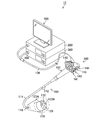
- FIG. 1 is a perspective view exemplifying the appearance of the endoscope system according to the embodiment of the present invention.
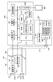
- FIG. 2 is a block diagram showing a configuration example of an endoscope system.
- FIG. 3 is a functional block diagram showing the functions of the medical image processing apparatus according to the first embodiment.
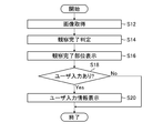
- FIG. 4 is a flowchart showing the operation of the medical image processing apparatus according to the first embodiment.
- FIG. 5 is an example 1 of a display image displayed on the screen of the monitor.
- FIG. 6 is an example 2 of a display image displayed on the screen of the monitor.
- FIG. 7 is an example 3 of a display image displayed on the screen of the monitor.
- FIG. 8 is an example 4 of a display image displayed on the screen of the monitor.
- FIG. 5 is an example 1 of a display image displayed on the screen of the monitor.
- FIG. 6 is an example 2 of a display image displayed on the screen of the monitor.
- FIG. 7 is an example 3 of a display image displayed on the screen
- FIG. 9 is an example of a display image when the display of the observation completion information based on the determination result of the observation completion determination is corrected to the information of the observation incomplete.
- FIG. 10 is an example of a display image when the display of the observation incomplete information based on the determination result of the observation completion determination is corrected to the observation completion information.
- FIG. 11 is an example of a display image when the display of the observation completion information of the portion based on the determination result of the observation completion determination is corrected to the observation completion information of another portion.
- FIG. 12 is an example of an observation image obtained while observing the cardia of the stomach.
- FIG. 13 is an example of another observation image obtained while observing the cardia of the stomach.
- FIG. 14 is a block diagram showing an example of the hardware configuration of the medical image processing apparatus according to the first embodiment.
- FIG. 15 is a functional block diagram showing the functions of the medical image processing apparatus according to the second embodiment.
- FIG. 16 is a block diagram showing an example of the hardware configuration of the medical image processing apparatus according to
- FIG. 1 is a perspective view exemplifying the appearance of the endoscope system 10 according to the embodiment of the present invention.
- the endoscope system 10 includes an endoscope scope 100, a processor device 200, a light source device 300, and a monitor 400.
- the endoscope scope 100 is an electronic endoscope, for example, a flexible endoscope.
- the endoscope scope 100 includes a hand operation unit 102, an insertion unit 104, and a universal cable 106.
- the hand operation unit 102 includes an angle knob 140, an air supply / water supply button 141, a suction button 142, a function button 143, and a shooting button 144.
- the angle knob 140 is used for a bending operation in which the bending direction and bending amount of the bending portion 114 in the insertion portion 104 are instructed.
- the angle knob 140 includes two types of knobs: a vertical angle knob that curves the curved portion 114 in the vertical direction, and a left and right angle knob that curves the curved portion 114 in the horizontal direction.
- the air supply water supply button 141 accepts the operation of the air supply instruction and the water supply instruction.
- the suction button 142 receives an operation of a suction instruction.
- Various functions are assigned to the function button 143.
- the function button 143 receives instruction operations for various functions.
- the shooting button 144 accepts a shooting instruction operation.
- the term "capture" includes the concepts of both still image capture and moving image capture.
- the shooting instruction operation includes an operation of instructing a shooting timing of a still image and an operation of instructing a shooting start timing and a shooting end timing of a moving image.
- the user grasps the hand operation unit 102, operates the endoscope scope 100, and observes the inside of the body by inserting the insertion unit 104 into the body of the subject.
- the "user” here refers to a doctor who is an operator.
- the description "subject” is synonymous with patient, subject or subject.
- the insertion portion 104 is a portion to be inserted into the body of the subject.
- the insertion portion 104 is continuously provided to the hand operation portion 102, and includes a soft portion 112, a curved portion 114, and a tip hard portion 116 in this order from the side of the hand operation portion 102.
- the flexible portion 112 is a flexible portion provided between the hand operation portion 102 and the curved portion 114.
- the bending portion 114 is a portion including a mechanism that can be bent by the operation of the hand operation portion 102. The user can bend the curved portion 114 by operating the angle knob 140 to change the direction of the hard tip portion 116 up, down, left and right.
- FIG. 1 is an enlarged view of a part of the hard tip portion 116.
- the hard tip 116 is provided with an imaging unit including a photographing lens 132, an illuminating unit including illuminating lenses 123A and 123B, and a forceps opening 126.
- the imaging unit is illustrated with reference numeral 130 in FIG.
- the illumination unit is illustrated with reference numeral 123 in FIG.
- Narrow band light includes at least one of red narrow band light, green narrow band light, blue narrow band light, and purple narrow band light.
- the washing water is discharged from the water supply nozzle (not shown), or the gas is discharged from the air supply nozzle (not shown).
- the cleaning water and gas can be used for cleaning the photographing lens 132 and the illuminating lenses 123A and 123B.
- the water supply nozzle and the air supply nozzle may be shared.
- the forceps opening 126 communicates with a treatment tool insertion passage (not shown) arranged inside the insertion portion 104.
- a treatment tool (not shown) is inserted through the treatment tool insertion passage.
- the hand operation unit 102 is provided with a treatment tool introduction port (not shown) for introducing the treatment tool into the treatment tool insertion passage.
- Treatment tools may include, for example, biopsy forceps, catheters, high frequency snares, and the like.
- the treatment tool also includes a guide tube, a tracal tube, a sliding tube and the like. The treatment tool is supported so as to be able to move forward and backward as appropriate in the treatment tool insertion passage. At the time of tumor removal or the like, the user can perform necessary treatment on the subject using a treatment tool.
- the universal cable 106 is a cable for connecting the endoscope scope 100 to the processor device 200 and the light source device 300.
- An electric cable and a light guide extending from the insertion portion 104 are inserted into the universal cable 106.
- the electric cable includes a communication cable used for signal transmission and a power supply cable used for power supply.
- the endoscope scope 100 is connected to the processor device 200 and the light source device 300 via a universal cable 106.
- the endoscope system 10 may include a foot switch (not shown) and / or a voice input device, etc., in addition to the hand operation unit 102, as an input device for inputting an instruction or the like from the user.
- the footswitch is equipped with a pedal and a cable.
- the footswitch cable is connected to the processor device 200.
- FIG. 2 is a block diagram showing a configuration example of the endoscope system 10.
- each configuration example will be described in the order of the endoscope scope 100, the light source device 300, and the processor device 200.
- the endoscope scope 100 includes an imaging unit 130 and an illumination unit 123.
- the image pickup unit 130 is arranged inside the tip rigid portion 116.
- the imaging unit 130 includes a photographing optical system including a photographing lens 132, an image pickup element 134, a drive circuit 136, and an analog front end (AFE) 138.
- AFE analog front end
- the photographing lens 132 is arranged on the tip end surface 116A of the tip hard portion 116.
- the image sensor 134 is arranged at the back of the photographing lens 132 (the position closer to the curved portion 114 than the distal end surface 116A).
- the image sensor 134 is, for example, a CMOS (Complementary Metal-Oxide Semiconductor) type image sensor.
- a CCD (Charge Coupled Device) type image sensor may be applied as the image sensor 134.
- the image sensor 134 is, for example, a color image sensor, and a plurality of pixels composed of a plurality of light receiving elements having a color filter (not shown) on the light receiving surface (imaging surface) of the image sensor 134 are formed by a specific pattern arrangement. It is dimensionally arranged. Each pixel of the image sensor 134 includes a microlens, a color filter, and a photoelectric conversion unit (photodiode or the like).
- the color filter for example, a primary color filter including red (R), green (G), and blue (B) is used.
- the arrangement form of the color pattern of the color filter is not particularly limited, and may be, for example, a Bayer arrangement.
- the image sensor 134 may include a pixel provided with a purple color filter corresponding to a purple light source (not shown) and / or an infrared filter corresponding to an infrared light source (not shown).
- the drive circuit 136 supplies various timing signals necessary for the operation of the image pickup device 134 to the image pickup device 134 based on the control signal transmitted from the processor device 200.
- the optical image of the subject to be observed is imaged on the light receiving surface of the image sensor 134 via the photographing lens 132.
- the image sensor 134 converts an optical image of a subject into an electric signal.
- the electric signal output from the image sensor 134 is converted into a digital image signal through processing by the analog front end 138.
- the analog front end 138 is equipped with an amplifier, a filter and an analog-to-digital converter.
- the analog front end 138 performs processing such as amplification, noise removal, and analog-to-digital conversion on the output signal of the image sensor 134.
- the output signal of the analog front end 138 is sent to the processor device 200.
- the image sensor 134, the drive circuit 136, and the analog front end 138 can be configured as a monolithic integrated circuit, and each of these circuit elements can be mounted on one image pickup chip.
- the lighting unit 123 includes lighting lenses 123A and 123B.
- the illumination lenses 123A and 123B are arranged at positions adjacent to the photographing lens 132 on the tip end surface 116A of the tip rigid portion 116.
- the emission end of the light guide 170 is arranged behind the illumination lenses 123A and 123B.
- the light guide 170 is inserted through the insertion unit 104, the hand operation unit 102, and the universal cable 106 shown in FIG.
- the incident end of the light guide 170 is arranged inside the light guide connector 108 provided at the end of the universal cable 106.
- the light source device 300 supplies illumination light to the light guide 170 via the light guide connector 108.
- the illumination light includes white light (light in a white wavelength band or light in a plurality of wavelength bands), light in one or a plurality of specific wavelength bands, or light in various wavelength bands depending on the observation purpose such as a combination thereof. Be selected.
- the specific wavelength band is narrower than the white wavelength band.
- the illumination light that irradiates the observation range is sometimes called observation light.
- the light source device 300 includes a light source 310 for illumination, an aperture 330, a condenser lens 340, and a light source control unit 350.
- the light source device 300 causes the observation light to be incident on the light guide 170.
- the light source 310 includes a red light source 310R, a green light source 310G, and a blue light source 310B.
- the red light source 310R, the green light source 310G, and the blue light source 310B emit red, green, and blue narrow-band light, respectively.
- the light source 310 can generate observation light that is an arbitrary combination of red, green, and blue narrow-band lights. For example, the light source 310 may combine red, green, and blue narrowband light to produce white light. Further, the light source 310 can generate narrow-band light by combining any two colors of red, green, and blue narrow-band light.
- the light source 310 can generate narrow-band light using any one color of red, green, and blue narrow-band light.
- the light source 310 may selectively switch and emit white light or narrow band light. Narrow band light is synonymous with special light.
- the light source 310 may include an infrared light source that emits infrared light, an ultraviolet light source that emits ultraviolet light, and the like.
- the light source 310 may employ an embodiment including a white light source that emits white light, a filter that allows white light to pass through, and a filter that allows narrow-band light to pass through.
- the light source 310 of this aspect can selectively emit either white light or narrow band light by switching between a filter that allows white light to pass through and a filter that allows narrow band light to pass through.
- the filter that passes narrow band light may include a plurality of filters corresponding to different bands.
- the light source 310 may selectively switch between a plurality of filters corresponding to different bands to selectively emit a plurality of narrow band lights having different bands.
- the type, wavelength band, etc. can be applied according to the type of observation target, the purpose of observation, and the like.
- Examples of the type of the light source 310 include a laser light source, a xenon light source, an LED (Light-Emitting Diode) light source, and the like.
- the incident end of the light guide 170 is arranged on the optical path of the emitted light of the condenser lens 340.
- the observation light emitted from the light source 310 reaches the incident end of the light guide 170 via the diaphragm 330 and the condenser lens 340.
- the observation light is transmitted to the illumination lenses 123A and 123B via the light guide 170, and is irradiated to the observation range from the illumination lenses 123A and 123B.
- the light source control unit 350 transmits a control signal to the light source 310 and the aperture 330 based on the instruction signal transmitted from the processor device 200.
- the light source control unit 350 controls the illuminance of the observation light emitted from the light source 310, the switching of the observation light, the on / off of the observation light, and the like.
- the processor device 200 includes an image input controller 202, an image processing unit 204, a communication control unit 205, a video output unit 206, and a storage unit 207. Further, the processor device 200 includes a CPU 210, a ROM 211, a RAM 212, an operation unit 208, a voice processing unit 209, and a speaker 209A.
- the image input controller 202 acquires an imaging signal from the endoscope scope 100.
- the image processing unit 204 generates an endoscopic image to be observed by processing the image pickup signal acquired via the image input controller 202.
- image includes the meaning of the image itself and the image data representing the image. Images include the concept of both moving and still images.
- the imaging signal output from the endoscope scope 100 may be understood as one aspect of the “endoscopic image”.
- the image processing unit 204 can perform image quality correction by applying digital signal processing such as white balance processing and shading correction processing to the input image pickup signal.
- the image processing unit 204 may be configured by using a digital signal processing circuit dedicated to image processing. Further, a part or all of the processing functions of the image processing unit 204 may be realized by executing the program by the CPU 210.
- the image processing unit 204 can generate one or more spectroscopic images based on the imaging signal obtained from the endoscope scope 100. Further, the image processing unit 204 may add incidental information defined by the DICOM (Digital Imaging and Communications in Medicine) standard to the endoscopic image.
- DICOM Digital Imaging and Communications in Medicine
- the storage unit 207 stores an endoscopic image generated by using the endoscope scope 100.
- the storage unit 207 can store various information (incidental information) incidental to the endoscopic image.
- the video output unit 206 transmits various display signals including an image generated by the image processing unit 204 to the monitor 400.
- the monitor 400 displays an image or the like to be observed according to the display signal output from the video output unit 206.
- the communication control unit 205 controls communication with a device that is communicably connected via a local area network (LAN: Local Area Network) in the hospital, a hospital information system (HIS), and the like.
- LAN Local Area Network
- HIS hospital information system
- the communication control unit 205 may apply a communication protocol conforming to the DICOM standard.
- the CPU 210 functions as an overall control unit that controls each unit in the processor device 200 and comprehensively controls the entire endoscope system 10.
- the CPU 210 functions as a memory controller that controls the ROM (Read Only Memory) 211 and the RAM (Random Access Memory) 212. Data such as various programs and control parameters for controlling the operation of the processor device 200 are stored in the ROM 211.
- the RAM 212 is used as a temporary storage area for data in various processes and a processing area for arithmetic processing using the CPU 210.
- the program executed by the CPU 210 is stored in the RAM 212.
- the RAM 212 can be used as a buffer memory when acquiring an imaging signal or an endoscopic image.
- the operation unit 208 accepts the user's operation and outputs an instruction signal according to the user's operation.
- the operation unit 208 is configured by using, for example, one or a combination of a keyboard, a mouse, a joystick, a touch panel, a foot switch, and a voice input device. It may be understood that switches such as the photographing button 144 provided on the endoscope scope are included in the operation unit 208.
- the CPU 210 acquires an instruction signal (user input signal) transmitted from the operation unit 208, and executes processing and control corresponding to the acquired user input signal.
- the voice processing unit 209 generates a voice signal representing information to be notified as voice.
- the speaker 209A converts the voice signal generated by using the voice processing unit 209 into voice. Examples of the voice output from the speaker 209A include a message, voice guidance, a warning sound, and the like.
- the processor device 200 performs various processes on the endoscope image generated by using the endoscope scope 100 or the endoscope image acquired via the communication control unit 205, and performs various processing on the endoscope image. And various information incidental to the endoscopic image is displayed on the monitor 400. Further, the processor device 200 can store the endoscopic image and various information incidental to the endoscopic image in the storage unit 207.
- the processor device 200 is equipped with an endoscopic image diagnosis support system using AI. Although the details will be described later, the processor device 200 recognizes which part of the body the endoscopic image of the observation target is, and determines whether or not the observation of the target part is completed. A function, a display control function for displaying the judgment result of the observation completion judgment on the monitor 400, a user input reception function for accepting user input including an instruction to correct the information of the displayed judgment result, and contents corrected by the user input. Is provided with a display correction function that reflects the above on the display.
- the processor device 200 is an example of the "medical image processing device” in the present disclosure.
- the monitor 400 is an example of a "display” in the present disclosure.
- the term “recognition” includes concepts such as identification, discrimination, reasoning, estimation, detection, and classification.
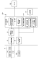
- FIG. 3 is a functional block diagram showing the functions of the medical image processing apparatus 20 according to the first embodiment of the present invention.
- the medical image processing device 20 includes an image acquisition unit 22, an observation completion determination unit 24, a display control unit 26, and a user input reception unit 28.
- the image acquisition unit 22 acquires an endoscope image 18 taken by using the endoscope scope 100.
- the endoscope image 18 may be an image represented by an imaging signal output from the endoscope scope 100, or an image generated by being processed by the image processing unit 204 shown in FIG. You may.
- the image input controller 202 shown in FIG. 2 can function as the image acquisition unit 22.
- the image acquisition unit 22 may be configured to include a communication interface for capturing the endoscopic image 18 from an external device via a communication line, or is stored in a portable information storage medium such as a memory card. It may be configured to include a media interface that captures endoscopic images.
- the communication control unit 205 shown in FIG. 2 can function as an image acquisition unit 22.
- the image acquisition unit 22 may be a data input interface and / or a data input terminal that receives the input of the endoscopic image 18 from the internal processing circuit of the processor device 200 shown in FIG.
- the image acquisition unit 22 may be a terminal that receives the input of the endoscopic image 18 generated by the image processing unit 204 of FIG.
- the endoscopic image 18 is an example of a "medical image" in the present disclosure.
- the image acquisition unit 22 can acquire a moving image 18A composed of a time-series frame image 18B taken by the endoscope scope 100. Further, when the still image shooting instruction is input from the user during the shooting of the moving image 18A and the still image 19 is shot, the image acquisition unit 22 shoots the still image 19 in response to the still image shooting instruction. Can be obtained.
- the observation completion determination unit 24 is a processing unit that recognizes the scene of the endoscopic image 18 acquired via the image acquisition unit 22 and determines the observation completion of the target portion.
- the observation completion determination is a process of determining whether or not the observation of the target site has been completed.
- the observation completion determination unit 24 performs a process in which the doctor who is the user actually consciously observes the target portion and estimates whether or not the observation is completed for that portion.
- the observation completion determination unit 24 is configured by using, for example, a part recognizer that recognizes the scene of the endoscope image 18 and performs an image classification process of assigning a label of the part reflected in the endoscope image 18. ..
- the site recognizer is constructed using, for example, a trained model such as a neural network learned by machine learning such as deep learning.
- the observation completion determination unit 24 can be configured by using a convolutional neural network (CNN).
- the observation completion determination unit 24 may be an AI module configured by using an AI model that performs tasks of recognizing the target portion and determining the observation completion of the target portion based on the endoscopic image 18.
- the observation completion determination unit 24 may be configured by a combination of a site recognizer and a determination device for the presence / absence of observation completion, and the site classification and the presence / absence of observation completion in response to the input of the endoscopic image 18. And may be constructed using the AI model learned by machine learning so as to output.
- the observation completion determination unit 24 can perform a process of recognizing a portion and determining the observation completion for each frame image of a part or all of the plurality of frame images 18B acquired in time series.
- the display control unit 26 controls the display content on the monitor 400. That is, the display control unit 26 generates a display signal necessary for display output to the monitor 400.
- the display signal includes, in addition to the display signal representing the endoscopic image 18, a display signal for notifying information indicating the determination result of the observation completion determination.
- the display control unit 26 includes a determination result information display control unit 26A and a display correction processing unit 26B.
- the determination result information display control unit 26A generates a display signal for displaying the determination result information obtained by the observation completion determination unit 24 on the monitor 400.
- the display signal generated by the determination result information display control unit 26A is output to the monitor 400.
- the monitor 400 displays information indicating the determination result of the observation completion determination, the endoscopic image 18, and the like according to the display signal from the display control unit 26.
- the user input receiving unit 28 receives a user input signal input using the input device 234.
- the user input signal includes an instruction signal for correcting the information of the observation completion determination result displayed on the monitor 400.
- the input device 234 corresponds to the operation unit 208 shown in FIG.
- the input device 234 may be, for example, a keyboard, a mouse, a touch panel, a foot switch, a voice input device, or an appropriate combination thereof.
- the user can input various instructions by operating the input device 234.
- the display correction processing unit 26B performs a process of correcting the information (display content) to be displayed on the monitor 400 according to the user input signal, and generates a display signal that reflects the correction content on the display.
- the display correction processing unit 26B may perform a process of rewriting the information of the determination result output from the observation completion determination unit 24, or may input the information of the determination result of the erroneous determination output from the observation completion determination unit 24 in the apparatus.
- the display content on the monitor 400 may be modified while holding the information on the monitor 400.
- the content corrected by the display correction processing unit 26B based on the user input signal is reflected in the display of the monitor 400.
- the display control unit 26 corresponds to the video output unit 206 shown in FIG.
- the CPU 210 shown in FIG. 2 can function as the observation completion determination unit 24.
- the combination of the image processing unit 204 and the CPU 210 shown in FIG. 2 may appropriately share the functions of the observation completion determination unit 24.
- FIG. 4 is a flowchart showing the operation of the medical image processing device 20. Each step of the flowchart of FIG. 4 is executed by executing a program by a processor such as a CPU 210 mounted on the medical image processing apparatus 20.
- a processor such as a CPU 210 mounted on the medical image processing apparatus 20.
- the medical image processing device 20 acquires an endoscopic image.
- the medical image processing device 20 recognizes the observation target portion and determines whether or not the observation of the portion is completed.
- the medical image processing device 20 causes the monitor 400 to display the information of the observation completed portion determined to have completed the observation based on the determination result of the observation completion determination.
- step S18 the medical image processing device 20 determines whether or not there is a user input including a correction instruction for the display content of the observation completed portion.
- the medical image processing device 20 proceeds to the user input information display step of step S20.
- step S20 the medical image processing device 20 reflects the correction content input by the user on the display of the monitor 400.
- step S18 if there is no input from the user instructing the correction of the display, the medical image processing apparatus 20 skips step S20 and maintains the display of the information of the observation completed portion indicated by the determination result of the observation completion determination in FIG. End the flowchart of.
- the medical image processing apparatus 20 can perform processing according to the flowchart of FIG. 4 for each of the plurality of frame images 18B sequentially acquired in time series.
- the operation method of the medical image processing device 20 shown in the flowchart of FIG. 4 may be understood as a diagnostic support method implemented by the medical image processing device 20, or an image processing method implemented by the medical image processing device 20. May be good.
- FIG. 5 is an example 1 of a display image displayed on the screen 40 of the monitor 400.
- FIG. 5 shows an example of an endoscopic image taken with a video flexible gastroduodenal endoscope.
- FIG. 5 is an example of an observation image of the upper body of the stomach.
- the screen 40 of the monitor 400 includes a main screen 42 and a sub screen 44.
- the endoscope image 18 as an observation image is displayed on the main screen 42.
- the endoscopic image 18 being photographed is displayed as a moving image in real time on the main screen 42.
- the main screen 42 functions as an observation image display area.
- the sub screen 44 displays information about the observation completion unit.
- the user operates the endoscope scope 100 while looking at the internal image (endoscopic image 18) displayed on the main screen 42.
- the observation completion information of the part is displayed on the sub screen 44.
- the medical image processing apparatus 20 determines whether or not the observation of a certain part is completed based on the scene recognition process for the endoscopic image 18, and subordinates the determination result by a display form such as a figure and / or a list. It is displayed on the screen 44.
- the main screen 42 is an example of the “first display area” in the present disclosure.
- the sub screen 44 is an example of the "second display area" in the present disclosure.
- FIG. 5 is a display example when it is determined that the observation of the upper body of the stomach is completed.
- the stomach is an example of a "part of the human body” in the present disclosure
- the schema image 46 is an example of a "model figure” in the present disclosure.
- character information indicating the determination result of the observation completion determination unit 24 is displayed. That is, on the second sub-screen 44B, the site information recognized as the observation target and the determination result information indicating the determination result of whether or not the observation is completed are displayed as information in character strings.
- the site information recognized as the observation target and the determination result information indicating the determination result of whether or not the observation is completed are displayed as information in character strings.
- an example in which "upper body of stomach" is displayed as site information and "observation completed" is displayed as judgment result information is shown.
- FIG. 6 is an example 2 of a display image displayed on the screen 40 of the monitor 400.
- FIG. 6 shows an example of an observation image of the rectum.
- FIG. 6 is a display example when it is determined that the rectal observation is completed by colonoscopy.
- the second sub-screen 44B of FIG. 6 shows an example in which the text information "rectum" is displayed as the site information recognized as the observation target and the "observation completed” is displayed as the judgment result information. Has been done.
- FIG. 7 is an example 3 of a display image displayed on the screen 40 of the monitor 400.
- the information of the observed portion may be listed and displayed as character information.
- the first sub-screen 44A in FIG. 7 displays a list of observed parts
- the second sub-screen 44B displays information on the currently observed part.
- the fundus, the upper body of the stomach, the middle body of the stomach, and the lower body of the stomach are listed as the observed sites.
- the endoscopic image 18 displayed on the first sub-screen 44A of FIG. 7 is an observation image that captures the vestibular portion of the stomach.
- the observation completion determination unit 24 determines that the observation of the vestibule portion has been completed
- the second sub-screen 44B displays character information indicating that the vestibule portion has been determined to be observation completion.
- FIG. 8 is an example of another display image displayed on the screen 40 of the monitor 400.
- the observed portion does not exist, and the information regarding the observed portion on the first sub-screen 44A is in a blank state.
- FIG. 8 shows a state when the observation completion determination unit 24 determines that the rectal observation is completed. In this case, on the second sub screen 44B, character information indicating that the rectum has been determined to be completed is displayed.
- FIG. 9 is an example of a display image when the display of the observation completion information based on the determination result of the observation completion determination is corrected to the information of the observation incomplete.
- the display content before the correction is shown on the left side, and the display content after the correction is shown on the right side.
- the observation completion determination unit 24 determines that the vestibule has been completed, and the screen 40 of the monitor 400 displays a display notifying the completion of the vestibular observation, as shown in the left figure of FIG.
- the area block 51 corresponding to the portion that has already been confirmed to have been observed is filled with, for example, a display color (for example, blue) indicating that the portion has been observed. Is displayed by. Then, assuming that the portion of the vestibule portion is newly determined to be the observation completed portion this time, the display indicating that the region block 52 corresponding to the vestibular portion in the schema image 46 is, for example, a portion newly determined to be the observation completed portion. Displayed by a color (eg orange) fill. Further, on the second sub screen 44B, character information indicating that the vestibular portion is determined to be completed is displayed.
- a display color for example, blue
- the observation completion information of the vestibular portion is confirmed as correct, and the display color of the area block 52 starts from orange. It turns blue.
- the "predetermined time” may be, for example, about several seconds.
- the display of the observation completed portion in the schema image 46 an example in which the definite display of “blue” is obtained via “orange” has been described, but it is not necessary to go through such a color change. ..
- the display content of the sub screen 44 shown on the left side of FIG. 9 is an example of the “observation completion display” in the present disclosure.
- the user operates the input device 234 to indicate "observation completed" of the vestibule. You can enter instructions to modify the content to a display indicating that "observation is incomplete”.
- the method of inputting the correction instruction by the user may be the character input for correcting the character information on the second sub screen 44B, or "observation incomplete" from the menu in which the correction candidates are presented such as the pull-down menu. It may be an operation of selecting.
- the modified content by the user input is reflected, and the display shown in the left figure of FIG. 9 is changed to the modified display content as shown in the right figure of FIG. Will be done.
- the area block 52 corresponding to the vestibule portion in the schema image 46 is displayed by a display color (for example, gray color) indicating that the observation is not completed, and the vestibule portion is displayed on the second sub screen 44B. Character information indicating that "observation is not completed" is displayed.
- the frame line of the area block 52 is shown by a broken line for convenience of illustration in order to clearly indicate the area block 52 whose display has been modified. Does not have to display such a border.
- the display content of the sub screen 44 shown on the right side of FIG. 9 is an example of the “observation incomplete display” in the present disclosure.
- FIG. 10 is an example of a display image when the display of the observation incomplete information based on the determination result of the observation completion determination is corrected to the observation completion information.
- the observation completion determination unit 24 determines that the vestibule portion has not been observed, and the screen 40 of the monitor 400 does not notify the observation completion information of the vestibule portion as shown in the left figure of FIG.
- the frame line of the area block 52 is shown by a broken line for convenience of illustration in order to clearly indicate that the area block 52 corresponding to the vestibule portion is “observation incomplete”. However, such a border is not displayed in the actual screen display.
- the user when the observation of the vestibule is completed in the actual observation by the user, the user operates the input device 234 to indicate "observation incomplete" of the vestibule. It is possible to input an instruction to modify the content of the display to a display indicating that "observation is completed".
- the modified content by the user input is reflected, and the display shown in the left figure of FIG. 10 is changed to the modified display content as shown in the right figure of FIG. Will be done.
- the area block 52 corresponding to the vestibule portion in the schema image 46 is displayed by a display color (for example, orange or blue) indicating that the observation is completed, and the vestibule portion is displayed on the second sub screen 44B. Character information indicating that "observation is completed" is displayed.
- FIG. 11 is an example of a display image when the display of the observation completion information of the portion based on the determination result of the observation completion determination is corrected to the observation completion information of another portion.
- the observation completion determination unit 24 determines that the vestibule has been completed, and the screen 40 of the monitor 400 is informed of the observation completion information for the vestibule as shown in the left figure of FIG. Further, in the schema image 46 of FIG. 11, the lower body of the stomach is displayed to indicate that the observation has not been completed.
- the user operates the input device 234. It is possible to input an instruction to correct the display of information regarding the observation completed site from the "vestibular region" to the "lower body of the stomach".
- the modified content by the user input is reflected, and the display shown in the left figure of FIG. 11 is changed to the modified display content as shown in the right figure of FIG. Will be done.
- the region block 53 corresponding to the lower body of the stomach in the schema image 46 is displayed by a display color (for example, orange or blue) indicating that the observation is completed, and the region block 52 corresponding to the vestibule portion 52. Is displayed by a display color (for example, gray color) indicating that the observation is not completed.
- Example of judgment criteria in observation completion judgment >> For example, the following conditions can be used as a determination criterion when the observation completion determination unit 24 determines that the observation is complete.
- the observation completion determination unit 24 determines that the observation is complete when at least one of these conditions 1 to 3 is satisfied.
- the observation completion determination unit 24 may determine that the observation is complete when two or more of these plurality of conditions are met.
- the "marker” in Condition 1 may be an anatomical landmark, for example, a specific pattern of the mucous membrane and / or a characteristic structure of the site.
- the mark is set for each part.
- the observation completion determination unit 24 recognizes the mark from the endoscopic image 18, it can determine that the observation is completed for the portion associated with the mark.
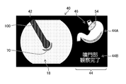
- FIG. 12 is an example of an observation image obtained while observing the cardia of the stomach.
- FIG. 12 shows an example when it is determined that the observation is completed because the condition 1 is satisfied. Since the cardia portion is observed by bending the curved portion 114 of the endoscope scope 100, the hole 70 of the cardia and the endoscope scope 100 are reflected in the endoscope image 18 at the time of observation. The hole 70 of the cardia and the endoscope scope 100 can serve as markers for the cardia portion.
- the observation completion determination unit 24 recognizes (detects) a mark from the endoscopic image 18, and determines that the observation is complete when the mark is present on the image.
- the observation completion determination unit 24 can determine that the observation of the cardia portion has been completed as satisfying the condition 1.
- the area block 54 corresponding to the cardia portion is displayed in the schema image 46 of the first sub-screen 44A by a display color indicating that the observation is completed. Further, on the second sub screen 44B, character information indicating that the observation of the cardia portion is completed is displayed.
- the observation completion determination unit 24 recognizes a site from the endoscopic image 18, and determines that the observation is complete when the same site exists on the image for a certain period of time or longer. For example, the observation completion determination unit 24 detects a part for each frame image 18B with respect to the frame image 18B acquired in time series at a specific time interval, and the number of frame images 18B in which the same part is detected is equal to or more than a predetermined number. If it is continuous, it can be determined that the observation of the site has been completed.
- the "fixed time" referred to in the condition 2 can be set to an appropriate value in advance, and may be, for example, about several seconds.
- FIG. 13 is an example of another observation image obtained while observing the cardia of the stomach.
- FIG. 13 shows an example when it is determined that the observation is completed because the condition 3 is satisfied.
- the hole 70 of the cardia is shown in the central portion of the endoscopic image 18.
- the observation completion determination unit 24 detects, for example, a target mark from the endoscopic image 18, recognizes the position of the mark in the image and the type (classification) of the part, and determines whether the mark exists in the center of the image. Judge whether or not. When the mark of the target portion exists in the central portion of the endoscopic image 18, the observation completion determination unit 24 can determine that the observation of the portion has been completed.
- the cardia portion is an example of a "specific part” in the present disclosure, and the hole 70 of the cardia is an example of a "mark” in the present disclosure.
- Condition 1 is an example of the "first condition” in the present disclosure.
- Condition 2 is an example of the "second condition” in the present disclosure.
- Condition 3 is an example of the "third condition” in the present disclosure.
- the criteria for determining the completion of observation are not limited to conditions 1 to 3.
- the observation completion determination unit 24 determines that the observation of the portion of the still image that is the subject of the still image has been completed. You may. That is, the observation completion determination unit 24 receives the input of the shooting instruction signal indicating the shooting timing of the still image, and when the input of the shooting instruction signal is received, determines that the observation is completed for the portion to be shot of the still image. May be good.
- Condition 4 that "a still image has been taken" is used as the determination criterion for the observation completion determination, and when the observation completion determination unit 24 meets one or more of the conditions 1 to 4. It may be determined that the observation is completed.
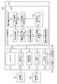
- FIG. 14 is a block diagram illustrating an exemplary hardware configuration of the medical image processing apparatus 20.
- the medical image processing device 20 is not limited to the form mounted on the processor device 200, and can be applied to an information processing device different from the processor device 200.
- the processing function of the medical image processing device 20 may be implemented in an image processing server or the like connected to the in-hospital network.
- the medical image processing device 20 can be realized by a computer system configured by using one or a plurality of computers. That is, the medical image processing device 20 is realized by installing a program on the computer.
- the medical image processing device 20 includes a processor 222, a non-temporary tangible computer-readable medium 224, an image input interface 225, an image processing processor 226, a communication interface 227, an input / output interface 228, and a bus 230.
- Processor 222 includes a CPU.
- the processor 222 may include a GPU (Graphics Processing Unit).
- the processor 222 is connected to a computer-readable medium 224, an image input interface 225, an image processing processor 226, a communication interface 227, and an input / output interface 228 via a bus 230.
- the medical image processing device 20 may further include an input device 234 and a display device 236. The input device 234 and the display device 236 are connected to the bus 230 via the input / output interface 228.
- the computer-readable medium 224 includes a memory that is a main storage device and a storage that is an auxiliary storage device.
- the computer-readable medium 224 may be, for example, a semiconductor memory, a hard disk (HDD: Hard Disk Drive) device, a solid state drive (SSD: Solid State Drive) device, or a combination of a plurality of these.
- the image input interface 225 can function as the image acquisition unit 22 shown in FIG.
- the medical image processing device 20 is connected to the endoscope scope 100 via the image input interface 225.
- the image processing processor 226 is a processor dedicated to image processing corresponding to the image processing unit 204 shown in FIG.
- the communication interface 227 corresponds to the communication control unit 205 shown in FIG.
- the medical image processing device 20 is connected to a communication line (not shown) via the communication interface 227.
- the communication line may be, for example, a local area network (LAN) constructed in the hospital.
- the communication network in the hospital is called the in-hospital network.
- the in-hospital network may be further connected to a wide area network such as the Internet via a router.
- An image storage server 500 such as a PACS (Picture Archiving and Communication Systems) server is connected to the in-hospital network.
- PACS Picture Archiving and Communication Systems
- the PACS server is a computer that stores and manages various data including medical images taken using various modality, and is equipped with a large-capacity external storage device and database management software.
- the PACS server communicates with other devices via the hospital network to send and receive various data including image data.
- the PACS server may be a DICOM server that operates based on the DICOM protocol.
- the medical image processing device 20 may acquire an endoscopic image from an image storage server 500 connected via a communication interface 227.
- the computer-readable medium 224 stores the observation completion determination program 240 and the display control program 260. Further, the computer-readable medium 224 includes an image storage unit 271, a determination information storage unit 272, and a user input information storage unit 273. The computer-readable medium 224 may store an image processing program (not shown) including an instruction for causing the processor 222 to execute a part or all of the processing as the image processing unit 204 described with reference to FIG.
- the image storage unit 271 is a storage area for storing the endoscopic image acquired via the image input interface 225 or the communication interface 227.
- the observation completion determination program 240 is a program including an instruction for causing the processor 222 to execute the process as the observation completion determination unit 24 described with reference to FIG.
- the display control program 260 is a program including instructions for causing the processor 222 to execute the process as the display control unit 26 described with reference to FIG.
- the display control program 260 includes a main screen control module 261, a sub screen control module 262, and a display correction module 263.
- the main screen control module 261 is a program module that controls the display of the main screen 42.
- the sub screen control module 262 is a program module that controls the display of the sub screen 44.
- the sub-screen control module 262 includes an instruction for causing the processor 222 to execute the process as the determination result information display control unit 26A described with reference to FIG.
- the display correction module 263 is a program module including an instruction for causing the processor 222 to execute the processing as the display correction processing unit 26B described with reference to FIG.
- a part or all of the display control program 260 may be incorporated in the observation completion determination program 240.
- the determination information storage unit 272 is a storage area for storing information on the determination result obtained by executing the observation completion determination program 240.
- the user input information storage unit 273 is a storage area for storing user input information input from the input device 234 via the input / output interface 228.
- the computer-readable medium 224 stores information on the target organ and a plurality of small parts (small areas) to be observed in a series of examinations for each type of examination performed using the endoscope system 10. There is. Specifically, for example, when performing an examination to observe all the internal parts of the stomach, the parts to be observed include the cardia, the fundus, the angular incisure, the upper body of the stomach, the middle body of the stomach, and the body of the stomach. The lower body, vestibule, and cardia are set.
- the classification label of the part is not limited to this example.
- the target of the site for determining the completion of observation is not limited to one organ, but may span multiple organs, for example, each site in the examination range including not only the stomach but also the esophagus and duodenum.
- the site of the esophagus for example, the upper part of the esophagus, the middle part of the esophagus, the lower part of the esophagus, etc.
- the site of the duodenum for example, classifications such as the duodenal bulb and the posterior duodenum are applied.
- the display device 236 may be, for example, a liquid crystal display, an organic electro-luminescence (OEL) display, a projector, or an appropriate combination thereof. In addition to the recognition result, the display device 236 can display various information such as an image to be processed and various setting information required for processing.
- the display device 236 corresponds to the monitor 400 shown in FIG.
- the display device 236 is an example of the "display" in the present disclosure.
- the judgment result of the observation completion judgment by the observation completion judgment program 240 is sent to the sub screen control module 262 and displayed on the sub screen 44.
- the display correction module 263 accepts the user input from the input device 234 and corrects the display content of the sub screen 44 according to the user input.
- the medical image processing apparatus 20 it is automatically determined from the endoscopic image 18 being observed whether or not the observation of the target portion is completed, and the information of the observation completed portion is transmitted to the monitor 400. It can be displayed. In addition, if the judgment result of the observation completion judgment of the part performed using AI and the judgment of the user (doctor) are different, the display showing the result of the observation completion judgment is corrected in response to the user's interaction. can do.
- the medical image processing apparatus 20 in the process of sequentially observing a plurality of parts, the observation behavior of the doctor is determined from the acquired endoscopic image 18 and the information of the observed part is provided in real time. can do. As a result, in an inspection that requires comprehensive observation of a plurality of parts, it is possible to provide the user with information on the observed part and information on the unobserved part in a timely manner. Oversight can be suppressed.
- FIG. 15 is a functional block diagram showing the functions of the medical image processing apparatus 20B according to the second embodiment.
- elements having the same or similar configurations as those shown in FIG. 3 are designated by the same reference numerals, and the description thereof will be omitted. Differences from the first embodiment will be described.
- the medical image processing device 20B shown in FIG. 15 has, in addition to the processing function of the medical image processing device 20 according to the first embodiment, a function of storing determination result information by the observation completion determination program 240 and correction information by the user, and a function thereof. It is implemented as a function to send the saved information to an external device (not shown).
- the medical image processing device 20B includes a correction information storage unit 274 and a communication unit 277.
- the correction information storage unit 274 shows the observation image that is the target of the judgment processing by the observation completion judgment unit 24, the judgment result information output by the observation completion judgment unit 24 based on the observation image, and the correction content by the user input. It is an information storage unit that stores user input information and information.
- the medical image processing device 20B When the user input reception unit 28 inputs a correction instruction by the user, the medical image processing device 20B includes the user input information, the determination result information before the correction that is the correction target by the user input, and the judgment result information. Is associated with the obtained observation image, that is, the observation image erroneously determined by the observation completion determination unit 24, and these data are stored in the correction information storage unit 274.
- the data stored in the correction information storage unit 274 can be used for improving the AI model applied to the observation completion determination unit 24 and the like. For example, by using the observation image erroneously determined by the observation completion determination unit 24 and the label of the correct determination result input by the user for the observation image as training data, additional learning about the AI model is performed. The determination accuracy can be improved.
- the data stored in the correction information storage unit 274 can be transmitted to an external device (not shown) via the communication unit 277. Further, the data stored in the correction information storage unit 274 can be stored in a portable storage medium (not shown) or the like and taken out of the medical image processing apparatus 20B.
- the communication unit 277 communicates with an external device (not shown) according to a predetermined communication protocol.
- the communication unit 277 has a configuration corresponding to the communication control unit 205 shown in FIG. 2 and the communication interface 227 shown in FIG.
- the communication unit 277 is an example of the "communication device" in the present disclosure.
- the external device may be, for example, a computer connected to the hospital network. Further, the external device may be a cloud server installed in a facility outside the hospital.
- the external device may be a computer system that executes machine learning of the AI model applied to the observation completion determination unit 24, or a data storage server that stores a learning data set for machine learning. May be good.
- the medical image processing device 20B may transmit the correction information or the like to an external device each time a user's correction instruction for displaying the judgment result of the observation completion judgment unit 24 is input, or at a predetermined communication timing.
- the data group may be transmitted when a certain amount or more of the data group is accumulated.
- FIG. 16 is a block diagram illustrating an exemplary hardware configuration of the medical image processing apparatus 20B according to the second embodiment.
- elements having the same or similar configurations as those shown in FIG. 14 are designated by the same reference numerals, and the description thereof will be omitted.
- the computer-readable medium 224 of the medical image processing apparatus 20B has a storage area as a correction information storage unit 274.
- the processor 222 observes that when the user inputs a correction instruction to the display of the judgment result of the observation completion judgment obtained by the observation completion judgment program 240, the judgment result targeted for the correction is obtained.
- the image, the determination result information, and the user input information indicating the correction content are associated with each other, and a process of storing these data in the correction information storage unit 274 is performed.
- the processor 222 can transmit the data stored in the correction information storage unit 274 to an external device (not shown) via the communication interface 227.
- the various processors include a CPU (Central Processing Unit), which is a general-purpose processor that executes programs and functions as various processing units, a GPU (Graphics Processing Unit), which is a processor specialized for image processing, and an FPGA (Field).
- Programmable Logic Device which is a processor whose circuit configuration can be changed after manufacturing (Programmable Gate Array), etc., is specially designed to execute specific processing such as ASIC (Application Specific Integrated Circuit).
- One processing unit may be composed of one of these various processors, or may be composed of two or more processors of the same type or different types.
- one processing unit may be composed of a plurality of FPGAs, a combination of a CPU and an FPGA, a combination of a CPU and a GPU, and the like.
- a plurality of processing units may be configured by one processor.
- one processor is configured by a combination of one or more CPUs and software, as represented by a computer such as a client or a server.
- the processor functions as a plurality of processing units.
- SoC System On Chip
- the various processing units are configured by using one or more of the above-mentioned various processors as a hardware-like structure.
- white light As the observation light, white light, light in one or a plurality of specific wavelength bands, or light in various wavelength bands according to the purpose of observation such as a combination thereof is selected.
- White light is light in a white wavelength band or light in a plurality of wavelength bands.
- the "specific wavelength band” is a band narrower than the white wavelength band. Specific examples regarding a specific wavelength band are shown below.
- a first example of a particular wavelength band is, for example, the blue or green band in the visible range.
- the wavelength band of the first example includes a wavelength band of 390 nm or more and 450 nm or less or a wavelength band of 530 nm or more and 550 nm or less, and the light of the first example is in the wavelength band of 390 nm or more and 450 nm or less or a wavelength of 530 nm or more and 550 nm or less. It has a peak wavelength in the band.
- a second example of a particular wavelength band is, for example, the red band in the visible range.
- the wavelength band of the second example includes a wavelength band of 585 nm or more and 615 nm or less or a wavelength band of 610 nm or more and 730 nm or less, and the light of the second example has a wavelength of 585 nm or more and 615 nm or less or 610 nm or more and 730 nm or less. It has a peak wavelength in the band.
- the third example of a specific wavelength band includes a wavelength band in which the extinction coefficient differs between oxidized hemoglobin and reduced hemoglobin, and the light in the third example has a peak wavelength in a wavelength band in which the extinction coefficient differs between oxidized hemoglobin and reduced hemoglobin.
- the wavelength band of the third example includes a wavelength band of 400 ⁇ 10 nm, 440 ⁇ 10 nm, a wavelength band of 470 ⁇ 10 nm, or a wavelength band of 600 nm or more and 750 nm or less, and the light of the third example is 400 ⁇ 10 nm. It has a peak wavelength in the wavelength band of 440 ⁇ 10 nm, 470 ⁇ 10 nm, or 600 nm or more and 750 nm or less.
- the fourth example of the specific wavelength band is used for observing the fluorescence emitted by the fluorescent substance in the living body (fluorescence observation), and the wavelength band of the excitation light that excites the fluorescent substance, for example, 390 nm to 470 nm.
- a fifth example of a specific wavelength band is the wavelength band of infrared light.
- the wavelength band of the fifth example includes a wavelength band of 790 nm or more and 820 nm or less or a wavelength band of 905 nm or more and 970 nm or less, and the light of the fifth example is within the wavelength band of 790 nm or more and 820 nm or less or a wavelength of 905 nm or more and 970 nm or less. It has a peak wavelength in the band.
- ⁇ Switching of observation light As the type of light source, a laser light source, a xenon light source, an LED (Light-Emitting Diode) light source, or an appropriate combination thereof may be adopted.
- the type and wavelength of the light source, the presence or absence of a filter, etc. are preferably configured according to the type of subject, the purpose of observation, etc., and when observing, the wavelength of the illumination light is combined according to the type of subject, the purpose of observation, etc. And / or switching is preferred.
- switching the wavelength for example, by rotating a disk-shaped filter (rotary color filter) arranged in front of the light source and provided with a filter that transmits or blocks light of a specific wavelength, the wavelength of the emitted light is switched. May be good.
- the image sensor used in the electronic endoscope is not limited to the color image sensor in which the color filter is arranged for each pixel, and may be a monochrome image sensor.
- the wavelength of the illumination light can be sequentially switched to perform surface-sequential (color-sequential) imaging.
- the wavelength of the emitted illumination light may be sequentially switched between purple, blue, green, and red, or a wide band light (white light) is irradiated and emitted by a rotary color filter (red, green, blue, etc.).
- the wavelength of the illumination light to be used may be switched.
- the wavelength of the illumination light emitted by the rotary color filter by irradiating one or a plurality of narrow band lights may be switched.
- the narrow band light may be infrared light having two or more wavelengths having different wavelengths.
- the processor device 200 may generate a special optical image having information in a specific wavelength band based on a normal optical image obtained by imaging with white light.
- the generation referred to here includes the concept of "acquisition".
- the processor device 200 functions as a special optical image acquisition unit.
- the processor device 200 transmits signals in a specific wavelength band to red (R), green (G), and blue (B), or cyan (C), magenta (M), and yellow (Y), which are usually contained in an optical image. ) Can be obtained by performing an operation based on the color information.
- the processor device 200 includes, as a medical image, a white band light, a normal light image obtained by irradiating light in a plurality of wavelength bands as white band light, and a special optical image obtained by irradiating light in a specific wavelength band. An operation based on at least one of the above can be used to generate a feature image.
- a feature image is a form of medical image.
- a phosphor may be arranged between the exit end of the light guide 170 and the illumination lenses 123A and 123B of the endoscope scope 100.
- the blue laser light that has passed through the light guide 170 irradiates the phosphor to excite the phosphor, and a part of the blue laser light passes through the phosphor and is emitted from the illumination lenses 123A and 123B as blue light. ..
- the phosphor is excited by blue laser light and emits a wide range of light (yellow as a color) from the wavelength range around the boundary between blue and green in the wavelength band of light to the wavelength range of red.
- the yellow light and the blue light transmitted through the phosphor are mixed to form white light, and the subject may be illuminated through the illumination lenses 123A and 123B.
- the blue light transmitted through the phosphor includes a part of the blue light emitted by the phosphor.
- the phosphor emits yellow light when irradiated with a blue laser light having a wavelength of 445 nm and transmits blue light having a wavelength of 445 nm, but when irradiated with a blue laser light having a wavelength of 405 nm, the phosphor emits yellow light. It may have the property of transmitting most of it.
- the blue light transmitted through the phosphor and the yellow light emitted by the phosphor are emitted. It is possible to control the ratio with.
- the endoscope scope 100 which is a flexible endoscope
- the endoscope for photographing the inside of the body is not limited to the flexible endoscope, and may be a rigid endoscope. It may be a capsule endoscope.
- the medical image handled by the medical image processing apparatus according to the present disclosure is not limited to an endoscopic image, and may be an image generated by another medical imaging apparatus such as an ultrasonic diagnostic apparatus.
- the medical imaging apparatus may be, for example, at least one of an X-ray imaging apparatus, a CT (Computed Tomography) imaging apparatus, an MRI (magnetic resonance imaging) imaging apparatus, and a nuclear medicine diagnostic apparatus.
- the technique of the present disclosure can be applied to a device that processes a medical image acquired by using these various medical imaging devices (modality).
- the medical image processing device of the present disclosure can be used as a diagnostic support device that supports medical examination, treatment, diagnosis, etc. by a doctor or the like.
- diagnostic support includes the concepts of medical examination support, treatment support, examination support, observation support, and lesion discrimination support.
- the display mode for notifying the user whether or not a plurality of parts have been comprehensively observed is not limited to the area display using model figures such as the schema image 46 and the list display using character information, and the progress of observation can be monitored. It may be a progress bar display or a checklist display in which a check mark is attached to the observed part.
- the medical image processing device is not limited to the form applied to the processor device 200 of the endoscope system 10 illustrated in FIG. 1, and various applications are possible.
- a medical image processing device can be applied to a medical information management system that manages various medical information including endoscopic images.
- the information management device in which the processing function of the medical image processing device according to the present disclosure is implemented may be installed in, for example, an operating room, an examination room, or a conference room in a hospital, or a medical institution in an out-of-hospital facility. Alternatively, it may be installed in a research institution.
- the information management device may be a workstation that supports medical examination, treatment, diagnosis, etc., or may be a business support device that supports medical work.
- the business support device may have a function of accumulating clinical information, supporting the creation of diagnostic documents, supporting the creation of reports, and the like.
- a program for realizing the functions of the medical image processing devices 20 and 20B described in the above-described embodiment on a computer is recorded on an optical disk, a magnetic disk, a semiconductor memory, or a computer-readable medium which is a non-temporary information storage medium such as a tangible object.
- a program through this information storage medium.
- the program signal instead of the mode in which the program is stored and provided in such a tangible non-temporary information storage medium, it is also possible to provide the program signal as a download service by using a telecommunication line such as the Internet.
- the medical image processing apparatus includes a medical image analysis processing unit and a medical image analysis result acquisition unit, and the medical image analysis processing unit is an area of interest based on the feature amount of pixels of a medical image.
- the medical image analysis result acquisition unit is a medical image processing device that detects an area and acquires the analysis result of the medical image analysis processing unit.
- the medical image analysis processing unit may include an image recognition unit.
- the medical image analysis processing unit detects the presence or absence of a noteworthy object based on the feature amount of the pixel of the medical image, and the medical image analysis result acquisition unit acquires the analysis result of the medical image analysis processing unit.
- Device The medical image analysis processing unit detects the presence or absence of a noteworthy object based on the feature amount of the pixel of the medical image, and the medical image analysis result acquisition unit acquires the analysis result of the medical image analysis processing unit.
- the medical image analysis result acquisition unit acquires from a recording device that records the analysis result of the medical image, and the analysis result is either a notable area included in the medical image or the presence or absence of a notable object.
- a medical imaging device that is, or both.
- a medical image is a medical image processing apparatus that is a normal light image obtained by irradiating light in a white band or light in a plurality of wavelength bands as light in a white band.
- a medical image is an image obtained by irradiating light in a specific wavelength band, and the specific wavelength band is a narrower band than the white wavelength band.
- a medical image processing device in which a specific wavelength band is a blue or green band in the visible range.
- a medical treatment in which a specific wavelength band includes a wavelength band of 390 nm or more and 450 nm or less or 530 nm or more and 550 nm or less, and light in a specific wavelength band has a peak wavelength in a wavelength band of 390 nm or more and 450 nm or less or 530 nm or more and 550 nm or less.
- Image processing device
- the specific wavelength band includes a wavelength band of 585 nm or more and 615 nm or less or 610 nm or more and 730 nm or less, and the light of the specific wavelength band has a peak wavelength in the wavelength band of 585 nm or more and 615 nm or less or 610 nm or more and 730 nm or less.
- Image processing device includes a wavelength band of 585 nm or more and 615 nm or less or 610 nm or more and 730 nm or less, and the light of the specific wavelength band has a peak wavelength in the wavelength band of 585 nm or more and 615 nm or less or 610 nm or more and 730 nm or less.
- the specific wavelength band includes a wavelength band in which the extinction coefficient differs between the oxidized hemoglobin and the reduced hemoglobin, and the light in the specific wavelength band has a peak wavelength in the wavelength band having a different extinction coefficient between the oxidized hemoglobin and the reduced hemoglobin.
- Medical image processing device includes a wavelength band in which the extinction coefficient differs between the oxidized hemoglobin and the reduced hemoglobin, and the light in the specific wavelength band has a peak wavelength in the wavelength band having a different extinction coefficient between the oxidized hemoglobin and the reduced hemoglobin.
- the specific wavelength band includes 400 ⁇ 10 nm, 440 ⁇ 10 nm, 470 ⁇ 10 nm, or 600 nm or more and 750 nm or less, and the light in the specific wavelength band is 400 ⁇ 10 nm, 440 ⁇ 10 nm, 470 ⁇ .
- a medical image processing apparatus having a peak wavelength in a wavelength band of 10 nm or 600 nm or more and 750 nm or less.
- the medical image is an in-vivo image of the inside of the living body, and the in-vivo image is a medical image processing device having information on fluorescence emitted by a fluorescent substance in the living body.
- Fluorescence is a medical image processing device obtained by irradiating a living body with excitation light having a peak wavelength of 390 nm or more and 470 nm or less.
- a medical image is an in-vivo image of the inside of a living body, and a specific wavelength band is a wavelength band of infrared light.
- a medical image in which a specific wavelength band includes a wavelength band of 790 nm or more and 820 nm or less or 905 nm or more and 970 nm or less, and light in a specific wavelength band has a peak wavelength in a wavelength band of 790 nm or more and 820 nm or less or 905 nm or more and 970 nm or less. Processing equipment.
- the medical image acquisition unit acquires a special optical image having information in a specific wavelength band based on a normal light image obtained by irradiating light in a white band or light in a plurality of wavelength bands as light in the white band.
- a medical image processing device equipped with an optical image acquisition unit and a medical image is a special optical image.
- Appendix 17 A medical image processing device that obtains a signal in a specific wavelength band by calculation based on RGB or CMY color information included in a normal optical image.
- a medical image processing device including a feature amount image generation unit that generates a feature amount image, and the medical image is a feature amount image.
- Endoscope system 18 Endoscope image 18A Moving image 18B Frame image 19 Still image 20, 20B Medical image processing device 22 Image acquisition unit 24 Observation completion judgment unit 26 Display control unit 26A Judgment result information display control unit 26B Display correction processing Part 28
- User input reception part 40 Screen 42 Main screen 44 Sub screen 44A 1st sub screen 44B 2nd sub screen 46 Schema image 47 Observation completed part 48 Observation incomplete part 51, 52, 53, 54 Area block 70 Hole 100 Internal view Mirror scope 102 Hand operation part 104 Insertion part 106 Universal cable 108 Light guide connector 112 Flexible part 114 Curved part 116 Tip hard part 116A Tip side end face 123 Illumination part 123A, 123B Illumination lens 126 Force opening 130 Imaging part 132 Imaging lens 134 Imaging Element 136 Drive circuit 138 Analog front end 140 Angle knob 141 Air supply / water supply button 142 Suction button 143 Function button 144 Shooting button 170 Light guide 200 Processor device 202 Image input controller 204 Image processing unit 205
Abstract
Provided are a medical image processing device, an endoscope system, a diagnosis assistance method, and a program capable of addressing erroneous determination and prevents a medical doctor from overlooking a site to be observed while utilizing observation completion determination using image processing. The medical image processing device is provided with at least one processor. The at least one processor acquires a medical image, makes observation completion determination, on the basis of the medical image, as to whether or not observation of a target portion has been completed, performs display control for displaying a determination result of the observation completion determination on a display, receives a user input including an instruction for correcting a display content indicating the determination result of the observation completion determination, and reflects in the display the content corrected by the user input.
Description
本発明は医療画像処理装置、内視鏡システム、診断支援方法及びプログラムに関する。
The present invention relates to a medical image processing device, an endoscopic system, a diagnostic support method and a program.
内視鏡検査においては、検査の対象とする臓器等における複数の部位について網羅的に観察することが求められる。特許文献1には、検査の対象とする臓器について必須の撮影部位が定められている場合に、撮影漏れを抑制するための支援技術が提案されている。特許文献1に記載の画像表示装置は、内視鏡画像から所定の解剖学的ランドマークを検出し、検査対象の臓器における既撮影領域と未撮影領域とを表すマップ画像を生成してモニタにマップ画像を表示させる。
In endoscopy, it is required to comprehensively observe multiple parts of the organ to be examined. Patent Document 1 proposes an assistive technique for suppressing omission of imaging when an essential imaging site is defined for an organ to be inspected. The image display device described in Patent Document 1 detects a predetermined anatomical landmark from an endoscopic image, generates a map image showing a photographed area and an unphotographed area in the organ to be inspected, and displays the map on the monitor. Display the map image.
特許文献2には、機械学習を用いた画像認識の技術が記載されている。特許文献2に記載の画像認識装置は、入力画像データについてのクラス認識の処理を行い、そのクラス認識結果を表示装置に表示させる。特許文献2に記載の画像認識装置は、クラス認識結果に対するユーザの評価を受け付け、ユーザによる評価結果と入力画像データとを学習データとして用いて識別部についての追加学習を行うことで、認識精度の向上を図っている。特許文献2の段落0057によれば、画像認識装置は内視鏡コントロールユニットに搭載される。
Patent Document 2 describes a technique of image recognition using machine learning. The image recognition device described in Patent Document 2 performs a class recognition process on the input image data, and displays the class recognition result on the display device. The image recognition device described in Patent Document 2 accepts the user's evaluation of the class recognition result, and uses the user's evaluation result and the input image data as learning data to perform additional learning about the identification unit to improve the recognition accuracy. We are trying to improve. According to paragraph 0057 of Patent Document 2, the image recognition device is mounted on the endoscope control unit.
内視鏡等の医療機器を用いた検査では、検査の目的に応じて対象とする部位の全箇所を網羅的に診断しなければならない。例えば胃の内部部位を詳細に分けると10か所以上の小部位から構成されており、医師が胃の内部を観察する場合に一部の部位を見落とす可能性がある。医療画像の分野では人工知能(AI:Artificial Intelligence)を利用して様々な支援を行う技術の開発が進められており、内視鏡画像等の医療画像に対して画像認識技術を利用することにより、医師が特定の部位の観察を完了したか否かを自動的に判定し、その判定結果を表示することにより、観察漏れ(見落とし)を抑制することが期待される。
In an examination using a medical device such as an endoscope, it is necessary to comprehensively diagnose all parts of the target part according to the purpose of the examination. For example, if the internal part of the stomach is divided in detail, it is composed of 10 or more small parts, and when the doctor observes the inside of the stomach, some parts may be overlooked. In the field of medical imaging, the development of technology that provides various support using artificial intelligence (AI) is underway, and by using image recognition technology for medical images such as endoscopic images, It is expected that omission of observation (oversight) can be suppressed by automatically determining whether or not the doctor has completed the observation of a specific part and displaying the determination result.
しかし、観察すべき部位の見落としを抑制するための深層学習等を使ったAIによる部位の観察完了判定は、医師による観察完了の判断基準と異なる場合がある。ある部位について観察を完了したか否かは、医師が意識的に観察を行ったかどうかという医師自身の主観的な要素も含まれるため、引用文献2に記載されているような画像解析に基づく通常の画像分類のタスクでは判定が難しい場合がある。ある部位についてAIが観察完了と判定した場合でも、実際には医師が観察を行っていないか、若しくは観察の程度が不十分であるというケースが想定され、AIによる観察完了判定と人間の判断とに食い違い(不一致)が発生し得る。
However, the judgment of the completion of observation of the part by AI using deep learning or the like to suppress the oversight of the part to be observed may differ from the judgment criteria of the completion of observation by the doctor. Whether or not the observation of a certain part is completed includes the subjective factor of the doctor himself, such as whether or not the doctor consciously observed the part. Therefore, it is usually based on image analysis as described in Cited Document 2. It may be difficult to make a judgment in the image classification task of. Even if the AI determines that the observation is complete for a certain part, it is assumed that the doctor is not actually observing or the degree of observation is insufficient. There may be discrepancies (mismatches).
上述したこれらの課題は、内視鏡検査に限らず、各種の医療画像について、ある部位の観察を完了したかどうかの判定処理を行う場合に想定される共通の課題である。
These issues described above are not limited to endoscopy, but are common issues that can be assumed when performing a determination process for determining whether or not observation of a certain part has been completed for various medical images.
本発明はこのような事情に鑑みてなされたもので、上述した複数の課題のうちの少なくとも1つの課題を解決し、画像処理を用いた観察完了判定を利用しつつ、誤判定への対処が可能であり、医師による観察対象の部位の見落としを抑制できる医療画像処理装置、内視鏡システム、診断支援方法及びプログラムを提供することを目的とする。
The present invention has been made in view of such circumstances, and it is possible to solve at least one of the above-mentioned problems and deal with erroneous judgments while utilizing the observation completion judgment using image processing. It is an object of the present invention to provide a medical image processing device, an endoscopic system, a diagnostic support method and a program capable of suppressing oversight of an observation target site by a doctor.
本開示の一態様に係る医療画像処理装置は、少なくとも1つのプロセッサを有する医療画像処理装置であって、少なくとも1つのプロセッサは、医療画像を取得し、医療画像に基づき対象部位について観察が完了したか否かの観察完了判定を行い、観察完了判定の判定結果をディスプレイに表示させる表示制御を行い、観察完了判定の判定結果を示す表示内容を修正する指示を含むユーザ入力を受け付け、ユーザ入力によって修正された内容を表示に反映させる。
The medical image processing apparatus according to one aspect of the present disclosure is a medical image processing apparatus having at least one processor, and the at least one processor acquires a medical image and observes the target site based on the medical image. Whether or not the observation completion judgment is performed, the display control for displaying the judgment result of the observation completion judgment is performed, the user input including the instruction to modify the display content indicating the judgment result of the observation completion judgment is accepted, and the user input is used. Reflect the modified content on the display.
本態様の医療画像処理装置によれば、医療画像を処理することによって得られる部位の観察完了判定の判定結果がディスプレイに表示される。ユーザは判定結果の表示に対して修正を加えるユーザ入力を行うことができる。ユーザ入力によって指示された修正内容はディスプレイの表示に反映され、部位の観察完了又は観察未完了を報知する表示が変更される。
According to the medical image processing apparatus of this embodiment, the determination result of the observation completion determination of the portion obtained by processing the medical image is displayed on the display. The user can input a user to modify the display of the determination result. The correction content instructed by the user input is reflected on the display, and the display for notifying the completion of observation or the incomplete observation of the part is changed.
「修正された内容を表示に反映させる」という記載は、修正内容を表示させること、すなわち、修正を反映した修正後の内容を表示させること、と理解してよい。
The description "reflecting the corrected content on the display" may be understood as displaying the corrected content, that is, displaying the corrected content reflecting the correction.
本態様の医療画像処理装置では、少なくとも1つのプロセッサが医療画像を処理することによって得られる部位の観察完了判定と、医師(ユーザ)の判断とが異なった場合、ユーザのインタラクションを受けて、判定結果の表示をユーザ入力に従い修正することができる。これにより、観察完了部位に関する正しい情報を表示させることが可能となり、部位の見落としを抑制する支援が可能である。
In the medical image processing apparatus of this embodiment, when the observation completion determination of the part obtained by processing the medical image by at least one processor and the determination of the doctor (user) are different, the determination is made by receiving the interaction of the user. The result display can be modified according to user input. As a result, it is possible to display the correct information about the observation completed part, and it is possible to support the suppression of oversight of the part.
医療画像処理装置は、単一の装置として構成されてもよいし、複数の装置を組み合わせて構成されてもよい。例えば、医療画像処理装置は、1台又は複数台のコンピュータを用いて実現し得る。「装置」という記載は、「システム」及び「モジュール」の概念を含む。
The medical image processing device may be configured as a single device or may be configured by combining a plurality of devices. For example, a medical image processing apparatus can be realized by using one or a plurality of computers. The description "device" includes the concepts of "system" and "module".
本開示の他の態様に係る医療画像処理装置において、観察完了判定の判定結果を表示するディスプレイをさらに備える構成とすることができる。
The medical image processing apparatus according to another aspect of the present disclosure may be further provided with a display for displaying the determination result of the observation completion determination.
本開示の他の態様に係る医療画像処理装置において、少なくとも1つのプロセッサは、特定の部位の目印が医療画像の画像上に存在する場合に特定の部位について観察完了と判定する構成とすることができる。
In the medical image processing apparatus according to another aspect of the present disclosure, at least one processor may be configured to determine that the observation is completed for the specific part when the mark of the specific part is present on the image of the medical image. can.
「目印」とは、ランドマークであり、部位の特徴的な形状及び/又は模様などであってもよいし、特定の部位と共に画像上に写る内視鏡の一部など人体以外の部材が含まれてよい。
The "mark" is a landmark, which may be a characteristic shape and / or pattern of a part, and includes a member other than the human body such as a part of an endoscope reflected on an image together with a specific part. You can do it.
「特定の部位」は、検査の対象とする臓器の一部、すなわち小部位であってもよいし、臓器の全体であってもよい。複数の部位を網羅的に観察する場合、複数の部位のそれぞれを「特定の部位」として設定しておくことができる。
The "specific part" may be a part of the organ to be examined, that is, a small part, or the whole organ. When observing a plurality of parts comprehensively, each of the plurality of parts can be set as a "specific part".
本開示の他の態様に係る医療画像処理装置において、少なくとも1つのプロセッサは、特定の部位が医療画像の画像上に一定時間以上存在する場合に特定の部位について観察完了と判定する構成とすることができる。
In the medical image processing apparatus according to another aspect of the present disclosure, at least one processor shall be configured to determine that the observation is completed for the specific part when the specific part is present on the image of the medical image for a certain period of time or longer. Can be done.
例えば、動画像のような時系列の医療画像において、同じ部位が画像上に一定時間存在する場合は、その特定の部位について医師が意識的な観察を行ったものと推定することができる。ここでの「一定時間」とは、予め定められた時間の長さである。
For example, in a time-series medical image such as a moving image, if the same part exists on the image for a certain period of time, it can be estimated that the doctor has consciously observed the specific part. The "fixed time" here is a predetermined length of time.
本開示の他の態様に係る医療画像処理装置において、少なくとも1つのプロセッサは、特定の部位の目印が医療画像の中央部に存在する場合に特定の部位について観察完了と判定する構成とすることができる。
In the medical image processing apparatus according to another aspect of the present disclosure, at least one processor may be configured to determine that observation is completed for a specific part when a mark of the specific part is present in the central part of the medical image. can.
「中央部」という記載は、厳密な中央に限らず、医療画像の画像領域における概ね中央の部分と理解される範囲を含む。医師が特定の部位に注目して意識的に観察を行う場合、その対象物は画像の中央部に捉えられることが多いと考えられる。
The description "central part" is not limited to the exact center, but includes a range that is generally understood as the central part in the image area of the medical image. When a doctor pays attention to a specific part and consciously observes it, it is considered that the object is often captured in the center of the image.
本開示の他の態様に係る医療画像処理装置において、特定の部位の目印が医療画像の画像上に存在することを第1の条件とし、特定の部位が医療画像の画像上に一定時間以上存在することを第2の条件とし、特定の部位の目印が医療画像の中央部に存在することを第3の条件とする場合に、少なくとも1つのプロセッサは、第1の条件、第2の条件、及び第3の条件のうち少なくとも1つの条件に適合する場合に特定の部位について観察完了と判定する構成とすることができる。
In the medical image processing apparatus according to another aspect of the present disclosure, the first condition is that a mark of a specific part exists on the image of the medical image, and the specific part exists on the image of the medical image for a certain period of time or more. When the second condition is to do so, and the third condition is that the mark of a specific part exists in the central part of the medical image, at least one processor has the first condition, the second condition, and the like. And, when at least one of the third conditions is met, it can be determined that the observation is completed for a specific part.
少なくとも1つのプロセッサは、第1の条件、第2の条件、及び第3の条件のうちいずれか1つの条件に適合する場合に観察完了と判定してもよいし、2つ以上の条件に適合する場合に観察完了と判定してもよい。
At least one processor may determine that the observation is complete when any one of the first condition, the second condition, and the third condition is satisfied, or the observation is completed, or two or more conditions are satisfied. If this is the case, it may be determined that the observation is complete.
本開示の他の態様に係る医療画像処理装置において、少なくとも1つのプロセッサは、静止画像の撮影タイミングを示す撮影指示信号の入力を受け付け、撮影指示信号の入力を受けた場合に、静止画像の撮影対象である部位について観察完了と判定する構成とすることができる。
In the medical image processing apparatus according to the other aspect of the present disclosure, at least one processor receives an input of a shooting instruction signal indicating a shooting timing of a still image, and when the input of the shooting instruction signal is received, the still image is captured. It can be configured to determine that the observation is completed for the target part.
本開示の他の態様に係る医療画像処理装置において、メモリをさらに備え、メモリには、医療画像及び観察完了判定の判定結果を示す判定結果情報が記憶され、少なくとも1つのプロセッサがユーザ入力を受けた場合、メモリには、ユーザ入力情報と、ユーザ入力による修正対象とされた判定結果情報と、判定結果情報が得られた医療画像と、が紐付けされて保存される構成とすることができる。
The medical image processing apparatus according to another aspect of the present disclosure further includes a memory, in which the medical image and the determination result information indicating the determination result of the observation completion determination are stored, and at least one processor receives user input. In this case, the memory can be configured to store the user input information, the determination result information to be corrected by the user input, and the medical image from which the determination result information is obtained in association with each other. ..
この態様によれば、少なくとも1つのプロセッサが観察完了判定を誤った医療画像とその医療画像に対する正しい判定結果の情報とがメモリに保存される。このメモリに保存されたデータを学習データに利用して、観察完了判定の処理に用いる推論モデルの推論精度向上のための追加の学習及び/又は新たなモデルの開発などが可能である。
According to this aspect, the medical image in which the observation completion determination is erroneous by at least one processor and the information of the correct determination result for the medical image are stored in the memory. By using the data stored in this memory as training data, it is possible to perform additional learning and / or develop a new model for improving the inference accuracy of the inference model used in the process of determining the completion of observation.
本開示の他の態様に係る医療画像処理装置において、メモリと、通信装置と、をさらに備え、メモリには、医療画像及び観察完了判定の判定結果を示す判定結果情報が記憶され、少なくとも1つのプロセッサがユーザ入力を受けた場合、通信装置は、ユーザ入力情報と、ユーザ入力による修正対象とされた判定結果情報と、前記判定結果情報が得られた前記医療画像と、を外部機器へ送信する構成とすることができる。
The medical image processing apparatus according to another aspect of the present disclosure further includes a memory and a communication device, and the memory stores a medical image and determination result information indicating a determination result of observation completion determination, and at least one of them. When the processor receives the user input, the communication device transmits the user input information, the determination result information to be corrected by the user input, and the medical image from which the determination result information is obtained to an external device. It can be configured.
この態様によれば、少なくとも1つのプロセッサが観察完了判定を誤った医療画像とその医療画像に対する正しい判定結果の情報とが外部機器へ送信される。外部機器に送信されたデータは学習データに利用することができ、外部機器又は外部機器以外の他の機器において、観察完了判定の処理に用いる推論モデルの推論精度向上のための追加の学習及び/又は新たなモデルの開発などが可能である。
According to this aspect, the medical image in which the observation completion judgment is erroneous by at least one processor and the information of the correct judgment result for the medical image are transmitted to the external device. The data transmitted to the external device can be used for training data, and additional learning and / / for improving the inference accuracy of the inference model used for the processing of the observation completion determination in the external device or other devices other than the external device. Alternatively, it is possible to develop a new model.
本開示の他の態様に係る医療画像処理装置において、少なくとも1つのプロセッサは、観察完了判定の判定結果が観察未完了となっている部位の観察未完了表示について、観察完了であることを示す観察完了表示に修正するユーザ入力を受け付け、ユーザ入力に基づき、観察未完了表示の表示内容を、観察完了表示の表示内容に変更する構成とすることができる。
In the medical image processing apparatus according to the other aspect of the present disclosure, at least one processor indicates that the observation is completed for the observation incomplete display of the portion where the observation completion determination result is the observation incomplete. It is possible to accept the user input to be modified to the completion display and change the display content of the observation incomplete display to the display content of the observation completion display based on the user input.
本開示の他の態様に係る医療画像処理装置において、少なくとも1つのプロセッサは、観察完了判定の判定結果が観察完了となっている部位の観察完了表示について、観察未完了であることを示す観察未完了表示に修正するユーザ入力を受け付け、ユーザ入力に基づき、観察完了表示の表示内容を、観察未完了表示の表示内容に変更する構成とすることができる。
In the medical image processing apparatus according to another aspect of the present disclosure, at least one processor has not observed the observation completion display of the portion where the determination result of the observation completion determination is the observation completion, indicating that the observation has not been completed. It is possible to accept the user input to be modified to the completion display and change the display content of the observation completion display to the display content of the observation incomplete display based on the user input.
本開示の他の態様に係る医療画像処理装置において、少なくとも1つのプロセッサは、観察完了判定によって観察完了と判定された観察完了部位について部位情報の表示を、別の部位を示す部位情報の表示に修正するユーザ入力を受け付け、ユーザ入力に基づき、観察完了部位についての部位情報の表示内容を修正する構成とすることができる。
In the medical image processing apparatus according to another aspect of the present disclosure, at least one processor displays site information for an observation completed site determined to be completed by the observation completion determination, and displays site information indicating another site. It is possible to accept the user input to be corrected and modify the display content of the part information about the observation completed part based on the user input.
本開示の他の態様に係る医療画像処理装置において、少なくとも1つのプロセッサは、医療画像をディスプレイの第1表示領域に表示させ、観察完了判定の判定結果をディスプレイにおける第1表示領域と異なる第2表示領域に表示させる構成とすることができる。
In the medical image processing apparatus according to another aspect of the present disclosure, at least one processor displays a medical image in the first display area of the display, and the determination result of the observation completion determination is different from the first display area in the display. It can be configured to be displayed in the display area.
本開示の他の態様に係る医療画像処理装置において、少なくとも1つのプロセッサは、観察完了部位についての部位情報を、対象部位を含む人体の部位を模式的に表したモデル図形によって表示させる構成とすることができる。
In the medical image processing apparatus according to the other aspect of the present disclosure, at least one processor is configured to display the part information about the observation completed part by a model figure schematically representing the part of the human body including the target part. be able to.
モデル図形は、例えば、臓器の形状を模したシェーマ画像などであってよい。
The model figure may be, for example, a schema image that imitates the shape of an organ.
本開示の他の態様に係る医療画像処理装置において、少なくとも1つのプロセッサは、モデル図形において観察完了部位と観察未完了部位とを色分けして表示させる構成とすることができる。
In the medical image processing apparatus according to the other aspect of the present disclosure, at least one processor can be configured to display the observation completed portion and the observation uncompleted portion in a color-coded manner in the model figure.
かかる態様によれば、医師は観察完了部位と観察未完了部位とを一見して容易に把握することができる。
According to this aspect, the doctor can easily grasp the observation completed part and the observation uncompleted part at a glance.
本開示の他の態様に係る医療画像処理装置において、少なくとも1つのプロセッサは、観察完了部位についての部位情報を文字情報として表示させる構成とすることができる。
In the medical image processing apparatus according to the other aspect of the present disclosure, at least one processor can be configured to display the part information about the observation completed part as character information.
本開示の他の態様に係る医療画像処理装置において、ユーザが指示の入力を行う際に用いる入力装置をさらに備え、少なくとも1つのプロセッサは、入力装置からユーザ入力を受け付ける構成とすることができる。
The medical image processing device according to another aspect of the present disclosure is further provided with an input device used when a user inputs an instruction, and at least one processor can be configured to receive user input from the input device.
入力装置は、キーボード、タッチパネル、音声入力装置、内視鏡スコープに設けられたスイッチ、及びフットスイッチのうち少なくとも1つを含む構成であってよい。
The input device may be configured to include at least one of a keyboard, a touch panel, a voice input device, a switch provided on the endoscope, and a foot switch.
本開示の他の態様に係る医療画像処理装置において、少なくとも1つのプロセッサは、観察の対象とされる複数の部位が設定され、複数の部位の部位ごとに観察完了判定を行い、観察完了判定の判定結果に基づき、複数の部位のうちの観察完了部位を示す情報と観察未完了部位を示す情報とを表示させる構成であってよい。
In the medical image processing apparatus according to another aspect of the present disclosure, at least one processor sets a plurality of parts to be observed, makes an observation completion determination for each part of the plurality of parts, and determines the observation completion. Based on the determination result, the configuration may be such that the information indicating the observation completed part and the information indicating the observation uncompleted part among the plurality of parts are displayed.
かかる態様によれば、観察が完了した部位(観察完了部位)と観察が非完了である部位(観察未完了部位)とを明示的に分別してこれらの情報の表示を行うことができ、複数の部位を網羅的に観察することが求められる場合に、観察漏れ(部位の見落とし)を効果的に抑制することができる。
According to this aspect, it is possible to explicitly separate the part where the observation is completed (the part where the observation is completed) and the part where the observation is not completed (the part where the observation is not completed) and display the information. When it is required to comprehensively observe the site, omission of observation (oversight of the site) can be effectively suppressed.
本開示の他の態様に係る医療画像処理装置において、少なくとも1つのプロセッサは、ニューラルネットワークを用いて観察完了判定を行う構成とすることができる。
In the medical image processing apparatus according to another aspect of the present disclosure, at least one processor may be configured to perform observation completion determination using a neural network.
少なくとも1つのプロセッサは、深層学習などの機械学習によって部位認識及び観察完了判定のタスクを行うように学習された学習済みのモデルを用いて観察完了判定を行うことができる。
At least one processor can perform observation completion determination using a trained model trained to perform site recognition and observation completion determination tasks by machine learning such as deep learning.
本開示の他の態様に係る医療画像処理装置において、少なくとも1つのプロセッサは、時系列の医療画像を取得する構成とすることができる。
In the medical image processing apparatus according to another aspect of the present disclosure, at least one processor may be configured to acquire time-series medical images.
時系列の医療画像は、動画像であってもよいし、連写、若しくはインターバル撮影などのように、特定の時間間隔で撮影される画像群であってもよい。また、時系列による撮影の時間間隔は必ずしも一定でなくてもよい。
The time-series medical image may be a moving image, or may be a group of images taken at specific time intervals such as continuous shooting or interval shooting. In addition, the time interval of shooting in chronological order does not necessarily have to be constant.
医療画像は、内視鏡を用いて撮影された内視鏡画像であってよい。内視鏡は、内視鏡スコープであってよいし、カプセル内視鏡であってもよい。
The medical image may be an endoscopic image taken with an endoscope. The endoscope may be an endoscopic scope or a capsule endoscope.
本開示の他の態様に係る内視鏡システムは、内視鏡スコープと、少なくとも1つのプロセッサと、を備える内視鏡システムであって、少なくとも1つのプロセッサは、内視鏡スコープを用いて体内を撮影することによって得られる内視鏡画像を取得し、内視鏡画像に基づき対象部位について観察が完了したか否かの観察完了判定を行い、観察完了判定の判定結果をディスプレイに表示させる表示制御を行い、観察完了判定の判定結果を示す表示内容を修正する指示を含むユーザ入力を受け付け、ユーザ入力によって修正された内容を表示に反映させる。
An endoscopic system according to another aspect of the present disclosure is an endoscopic system comprising an endoscopic scope and at least one processor, the at least one processor using the endoscopic scope in the body. An endoscopic image obtained by taking an image is acquired, an observation completion judgment is made based on the endoscopic image whether or not the observation of the target part is completed, and the judgment result of the observation completion judgment is displayed on the display. It controls and accepts user input including an instruction to modify the display content indicating the judgment result of the observation completion determination, and reflects the content modified by the user input on the display.
本態様の内視鏡システムによれば、観察中の内視鏡画像に対してリアルタイムに観察完了判定の判定結果を表示させることが可能であり、誤った判定結果の表示が行われた場合に、ユーザは適時にその表示を正しい表示内容に修正することができる。
According to the endoscopic system of this aspect, it is possible to display the judgment result of the observation completion judgment in real time on the endoscopic image under observation, and when the wrong judgment result is displayed. , The user can timely modify the display to the correct display content.
本開示の他の態様に係る診断支援方法は、少なくとも1つのプロセッサが実施する診断支援方法であって、少なくとも1つのプロセッサが、医療画像を取得することと、医療画像に基づき対象部位について観察が完了したか否かの観察完了判定を行うことと、観察完了判定の判定結果をディスプレイに表示させる表示制御を行うことと、観察完了判定の判定結果を示す表示内容を修正する指示を含むユーザ入力を受け付けることと、ユーザ入力によって修正された内容を表示に反映させることと、を含む。
The diagnostic support method according to another aspect of the present disclosure is a diagnostic support method performed by at least one processor, in which at least one processor acquires a medical image and observes a target site based on the medical image. User input including an observation completion judgment as to whether or not the observation is completed, a display control for displaying the judgment result of the observation completion judgment on the display, and an instruction to modify the display content indicating the judgment result of the observation completion judgment. Includes accepting and reflecting the content modified by user input on the display.
本開示の他の態様に係るプログラムは、コンピュータに、医療画像を取得する機能と、医療画像に基づき対象部位について観察が完了したか否かの観察完了判定を行う機能と、観察完了判定の判定結果をディスプレイに表示させる表示制御を行う機能と、観察完了判定の判定結果を示す表示内容を修正する指示を含むユーザ入力を受け付ける機能と、ユーザ入力によって修正された内容を表示に反映させる機能と、を実現させるためのプログラムである。
The program according to another aspect of the present disclosure includes a function of acquiring a medical image on a computer, a function of determining whether or not the observation of the target site has been completed based on the medical image, and a determination of the observation completion determination. A function to control the display of the result on the display, a function to accept user input including an instruction to modify the display content indicating the judgment result of the observation completion judgment, and a function to reflect the content modified by the user input on the display. , Is a program to realize.
本発明によれば、医療画像の画像処理に基づき、対象とする部位について観察を完了したかどうかを判定してその判定結果を表示させることができ、判定結果に誤りがある場合にはユーザ入力によって正しい内容の表示に修正することができる。これにより、部位の見落としを抑制することができ、適正な検査の実施を支援することが可能になる。
According to the present invention, based on the image processing of the medical image, it is possible to determine whether or not the observation of the target portion is completed and display the determination result, and if there is an error in the determination result, the user inputs. Can be modified to display the correct content. As a result, oversight of the site can be suppressed, and it becomes possible to support the implementation of an appropriate inspection.
以下、添付図面に従って本発明の好ましい実施の形態について詳説する。本明細書では、同一の構成要素には同一の参照符号を付して、重複する説明は適宜省略する。
Hereinafter, preferred embodiments of the present invention will be described in detail with reference to the accompanying drawings. In the present specification, the same components are designated by the same reference numerals, and duplicate description will be omitted as appropriate.
《内視鏡システムの概要》
図1は、本発明の実施形態に係る内視鏡システム10の外観を例示的に示す斜視図である。内視鏡システム10は、内視鏡スコープ100と、プロセッサ装置200と、光源装置300と、モニタ400と、を備える。 << Overview of endoscopy system >>
FIG. 1 is a perspective view exemplifying the appearance of theendoscope system 10 according to the embodiment of the present invention. The endoscope system 10 includes an endoscope scope 100, a processor device 200, a light source device 300, and a monitor 400.
図1は、本発明の実施形態に係る内視鏡システム10の外観を例示的に示す斜視図である。内視鏡システム10は、内視鏡スコープ100と、プロセッサ装置200と、光源装置300と、モニタ400と、を備える。 << Overview of endoscopy system >>
FIG. 1 is a perspective view exemplifying the appearance of the
内視鏡スコープ100は電子内視鏡であり、例えば軟性内視鏡である。内視鏡スコープ100は、手元操作部102、挿入部104、及びユニバーサルケーブル106を備える。手元操作部102は、アングルノブ140、送気送水ボタン141、吸引ボタン142、機能ボタン143、及び撮影ボタン144を備える。
The endoscope scope 100 is an electronic endoscope, for example, a flexible endoscope. The endoscope scope 100 includes a hand operation unit 102, an insertion unit 104, and a universal cable 106. The hand operation unit 102 includes an angle knob 140, an air supply / water supply button 141, a suction button 142, a function button 143, and a shooting button 144.
アングルノブ140は、挿入部104における湾曲部114の湾曲方向及び湾曲量を指示する湾曲操作に用いられる。アングルノブ140は、湾曲部114を上下方向に湾曲させる上下アングルノブと、湾曲部114を左右方向に湾曲させる左右アングルノブとの2種類のノブを含む。
The angle knob 140 is used for a bending operation in which the bending direction and bending amount of the bending portion 114 in the insertion portion 104 are instructed. The angle knob 140 includes two types of knobs: a vertical angle knob that curves the curved portion 114 in the vertical direction, and a left and right angle knob that curves the curved portion 114 in the horizontal direction.
送気送水ボタン141は、送気指示及び送水指示の操作を受け付ける。吸引ボタン142は吸引指示の操作を受け付ける。機能ボタン143には各種の機能が割り付けられる。機能ボタン143は各種機能の指示操作を受け付ける。撮影ボタン144は撮影指示操作を受け付ける。「撮影」という用語には、静止画像の撮影及び動画像の撮影の両方の概念が含まれる。撮影指示操作には、静止画像の撮影タイミングを指示する操作、及び動画像の撮影開始タイミングと撮影終了タイミングとを指示する操作が含まれる。
The air supply water supply button 141 accepts the operation of the air supply instruction and the water supply instruction. The suction button 142 receives an operation of a suction instruction. Various functions are assigned to the function button 143. The function button 143 receives instruction operations for various functions. The shooting button 144 accepts a shooting instruction operation. The term "capture" includes the concepts of both still image capture and moving image capture. The shooting instruction operation includes an operation of instructing a shooting timing of a still image and an operation of instructing a shooting start timing and a shooting end timing of a moving image.
ユーザは、手元操作部102を把持して内視鏡スコープ100を操作し、挿入部104を被検体の体内に挿入することにより体内を観察する。ここでの「ユーザ」とは、術者である医師を指す。「被検体」という記載は、患者、被検者あるいは被検査者と同義である。
The user grasps the hand operation unit 102, operates the endoscope scope 100, and observes the inside of the body by inserting the insertion unit 104 into the body of the subject. The "user" here refers to a doctor who is an operator. The description "subject" is synonymous with patient, subject or subject.
挿入部104は、被検体の体内に挿入される部分である。挿入部104は、手元操作部102に連設されており、手元操作部102の側から順に、軟性部112、湾曲部114及び先端硬質部116を備える。
The insertion portion 104 is a portion to be inserted into the body of the subject. The insertion portion 104 is continuously provided to the hand operation portion 102, and includes a soft portion 112, a curved portion 114, and a tip hard portion 116 in this order from the side of the hand operation portion 102.
軟性部112は、手元操作部102と湾曲部114との間に設けられる可撓性を有する部分である。湾曲部114は、手元操作部102の操作によって湾曲可能な機構を含む部分である。ユーザはアングルノブ140を操作することにより湾曲部114を湾曲させて、先端硬質部116の向きを上下左右に変えることができる。
The flexible portion 112 is a flexible portion provided between the hand operation portion 102 and the curved portion 114. The bending portion 114 is a portion including a mechanism that can be bent by the operation of the hand operation portion 102. The user can bend the curved portion 114 by operating the angle knob 140 to change the direction of the hard tip portion 116 up, down, left and right.
図1には先端硬質部116の一部を拡大して図示する。先端硬質部116には、撮影レンズ132を含む撮像部と、照明用レンズ123A,123Bを含む照明部と、鉗子口126とが設けられる。なお、撮像部は図2において符号130を付して図示する。また、照明部は図2において符号123を付して図示する。
FIG. 1 is an enlarged view of a part of the hard tip portion 116. The hard tip 116 is provided with an imaging unit including a photographing lens 132, an illuminating unit including illuminating lenses 123A and 123B, and a forceps opening 126. The imaging unit is illustrated with reference numeral 130 in FIG. Further, the illumination unit is illustrated with reference numeral 123 in FIG.
観察及び処置の際には、ユーザによる操作に応じて照明用レンズ123A,123Bを介して白色光及び/又は狭帯域光を照射することができる。狭帯域光には、赤色狭帯域光、緑色狭帯域光、青色狭帯域光、及び紫色狭帯域光のうち少なくとも1つが含まれる。
At the time of observation and treatment, white light and / or narrow band light can be irradiated through the illumination lenses 123A and 123B according to the operation by the user. Narrow band light includes at least one of red narrow band light, green narrow band light, blue narrow band light, and purple narrow band light.
また、送気送水ボタン141が操作された場合、不図示の送水ノズルから洗浄水が放出され、又は不図示の送気ノズルから気体が放出される。洗浄水及び気体は、撮影レンズ132及び照明用レンズ123A,123B等の洗浄に用いることができる。なお、送水ノズル及び送気ノズルを共通化してもよい。
Further, when the air supply water supply button 141 is operated, the washing water is discharged from the water supply nozzle (not shown), or the gas is discharged from the air supply nozzle (not shown). The cleaning water and gas can be used for cleaning the photographing lens 132 and the illuminating lenses 123A and 123B. The water supply nozzle and the air supply nozzle may be shared.
鉗子口126は、挿入部104の内部に配置される不図示の処置具挿通路と連通している。処置具挿通路には不図示の処置具が挿通される。手元操作部102には処置具を処置具挿通路内に導入するための不図示の処置具導入口が設けられている。処置具としては、例えば、生検鉗子、カテーテル、高周波スネアなどがあり得る。また、処置具には、カイドチューブ、トラカールチューブ、スライディングチューブなども含まれる。処置具は処置具挿通路において適宜進退可能に支持される。腫瘍摘出等の際に、ユーザは処置具を用いて被検体に対して必要な処置を施すことが可能である。
The forceps opening 126 communicates with a treatment tool insertion passage (not shown) arranged inside the insertion portion 104. A treatment tool (not shown) is inserted through the treatment tool insertion passage. The hand operation unit 102 is provided with a treatment tool introduction port (not shown) for introducing the treatment tool into the treatment tool insertion passage. Treatment tools may include, for example, biopsy forceps, catheters, high frequency snares, and the like. The treatment tool also includes a guide tube, a tracal tube, a sliding tube and the like. The treatment tool is supported so as to be able to move forward and backward as appropriate in the treatment tool insertion passage. At the time of tumor removal or the like, the user can perform necessary treatment on the subject using a treatment tool.
ユニバーサルケーブル106は、内視鏡スコープ100をプロセッサ装置200及び光源装置300に接続するためのケーブルである。ユニバーサルケーブル106には、挿入部104から延設される電気ケーブル及びライトガイドが挿通されている。電気ケーブルには、信号の伝達に用いる通信ケーブルと電力供給に用いる給電ケーブルとが含まれる。内視鏡スコープ100は、ユニバーサルケーブル106を介してプロセッサ装置200及び光源装置300と接続される。
The universal cable 106 is a cable for connecting the endoscope scope 100 to the processor device 200 and the light source device 300. An electric cable and a light guide extending from the insertion portion 104 are inserted into the universal cable 106. The electric cable includes a communication cable used for signal transmission and a power supply cable used for power supply. The endoscope scope 100 is connected to the processor device 200 and the light source device 300 via a universal cable 106.
なお、内視鏡システム10は、ユーザからの指示等を入力する入力装置として、手元操作部102の他に、不図示のフットスイッチ及び/又は音声入力装置などを備えてもよい。フットスイッチはペダルとケーブルとを備える。フットスイッチのケーブルはプロセッサ装置200と接続される。
Note that the endoscope system 10 may include a foot switch (not shown) and / or a voice input device, etc., in addition to the hand operation unit 102, as an input device for inputting an instruction or the like from the user. The footswitch is equipped with a pedal and a cable. The footswitch cable is connected to the processor device 200.
《内視鏡システムの構成例》
図2は、内視鏡システム10の構成例を示すブロック図である。以下、内視鏡スコープ100、光源装置300、及びプロセッサ装置200の順に、それぞれの構成例について説明する。 << Configuration example of endoscopic system >>
FIG. 2 is a block diagram showing a configuration example of theendoscope system 10. Hereinafter, each configuration example will be described in the order of the endoscope scope 100, the light source device 300, and the processor device 200.
図2は、内視鏡システム10の構成例を示すブロック図である。以下、内視鏡スコープ100、光源装置300、及びプロセッサ装置200の順に、それぞれの構成例について説明する。 << Configuration example of endoscopic system >>
FIG. 2 is a block diagram showing a configuration example of the
〔内視鏡スコープの説明〕
内視鏡スコープ100は、撮像部130と、照明部123と、を備える。撮像部130は先端硬質部116の内部に配置される。撮像部130は、撮影レンズ132を含む撮影光学系と、撮像素子134と、駆動回路136と、アナログフロントエンド(AFE:Analog Front End)138と、を備える。 [Explanation of endoscopic scope]
Theendoscope scope 100 includes an imaging unit 130 and an illumination unit 123. The image pickup unit 130 is arranged inside the tip rigid portion 116. The imaging unit 130 includes a photographing optical system including a photographing lens 132, an image pickup element 134, a drive circuit 136, and an analog front end (AFE) 138.
内視鏡スコープ100は、撮像部130と、照明部123と、を備える。撮像部130は先端硬質部116の内部に配置される。撮像部130は、撮影レンズ132を含む撮影光学系と、撮像素子134と、駆動回路136と、アナログフロントエンド(AFE:Analog Front End)138と、を備える。 [Explanation of endoscopic scope]
The
撮影レンズ132は先端硬質部116の先端側端面116Aに配置される。撮影レンズ132の奥(先端側端面116Aよりも湾曲部114に近い側の位置)には撮像素子134が配置される。撮像素子134は、例えば、CMOS(Complementary Metal-Oxide Semiconductor)型のイメージセンサである。撮像素子134としてCCD(Charge Coupled Device)型のイメージセンサを適用してもよい。
The photographing lens 132 is arranged on the tip end surface 116A of the tip hard portion 116. The image sensor 134 is arranged at the back of the photographing lens 132 (the position closer to the curved portion 114 than the distal end surface 116A). The image sensor 134 is, for example, a CMOS (Complementary Metal-Oxide Semiconductor) type image sensor. A CCD (Charge Coupled Device) type image sensor may be applied as the image sensor 134.
撮像素子134は、例えばカラー撮像素子であり、撮像素子134の受光面(撮像面)には不図示のカラーフィルタを備えた複数の受光素子により構成される複数の画素が特定のパターン配列によって2次元配置されている。撮像素子134の各画素は、マイクロレンズ、カラーフィルタ及び光電変換部(フォトダイオード等)を含んでいる。カラーフィルタとして、例えば、赤(R)、緑(G)、及び青(B)を含む原色カラーフィルタが用いられる。カラーフィルタの色パターンの配置形態は、特に限定されず、例えばベイヤー配列などであってよい。
The image sensor 134 is, for example, a color image sensor, and a plurality of pixels composed of a plurality of light receiving elements having a color filter (not shown) on the light receiving surface (imaging surface) of the image sensor 134 are formed by a specific pattern arrangement. It is dimensionally arranged. Each pixel of the image sensor 134 includes a microlens, a color filter, and a photoelectric conversion unit (photodiode or the like). As the color filter, for example, a primary color filter including red (R), green (G), and blue (B) is used. The arrangement form of the color pattern of the color filter is not particularly limited, and may be, for example, a Bayer arrangement.
また、撮像素子134は、不図示の紫色光源に対応した紫色カラーフィルタ、及び/又は不図示の赤外光源に対応した赤外用フィルタを備えた画素を含んでいてもよい。
Further, the image sensor 134 may include a pixel provided with a purple color filter corresponding to a purple light source (not shown) and / or an infrared filter corresponding to an infrared light source (not shown).
駆動回路136は、プロセッサ装置200から送信される制御信号に基づき、撮像素子134の動作に必要な各種のタイミング信号を撮像素子134へ供給する。
The drive circuit 136 supplies various timing signals necessary for the operation of the image pickup device 134 to the image pickup device 134 based on the control signal transmitted from the processor device 200.
観察対象である被写体の光学像は、撮影レンズ132を介して撮像素子134の受光面に結像される。撮像素子134は、被写体の光学像を電気信号へ変換する。撮像素子134から出力される電気信号はアナログフロントエンド138による処理を経てデジタル画像信号に変換される。
The optical image of the subject to be observed is imaged on the light receiving surface of the image sensor 134 via the photographing lens 132. The image sensor 134 converts an optical image of a subject into an electric signal. The electric signal output from the image sensor 134 is converted into a digital image signal through processing by the analog front end 138.
アナログフロントエンド138はアンプ、フィルタ及びアナログデジタル変換器を備える。アナログフロントエンド138は、撮像素子134の出力信号に対して、増幅、ノイズ除去及びアナログデジタル変換等の処理を施す。アナログフロントエンド138の出力信号はプロセッサ装置200へ送られる。なお、撮像素子134、駆動回路136、及びアナログフロントエンド138は、モノリシック集積回路として構成することができ、これらの各回路素子は、1つの撮像チップに搭載され得る。
The analog front end 138 is equipped with an amplifier, a filter and an analog-to-digital converter. The analog front end 138 performs processing such as amplification, noise removal, and analog-to-digital conversion on the output signal of the image sensor 134. The output signal of the analog front end 138 is sent to the processor device 200. The image sensor 134, the drive circuit 136, and the analog front end 138 can be configured as a monolithic integrated circuit, and each of these circuit elements can be mounted on one image pickup chip.
照明部123は、照明用レンズ123A,123Bを備える。照明用レンズ123A,123Bは、先端硬質部116の先端側端面116Aにおいて撮影レンズ132の隣接位置に配置される。照明用レンズ123A,123Bの奥に、ライトガイド170の射出端が配置される。
The lighting unit 123 includes lighting lenses 123A and 123B. The illumination lenses 123A and 123B are arranged at positions adjacent to the photographing lens 132 on the tip end surface 116A of the tip rigid portion 116. The emission end of the light guide 170 is arranged behind the illumination lenses 123A and 123B.
ライトガイド170は、図1に示す挿入部104、手元操作部102及びユニバーサルケーブル106に挿通される。ライトガイド170の入射端は、ユニバーサルケーブル106の端部に設けられたライトガイドコネクタ108の内部に配置される。
The light guide 170 is inserted through the insertion unit 104, the hand operation unit 102, and the universal cable 106 shown in FIG. The incident end of the light guide 170 is arranged inside the light guide connector 108 provided at the end of the universal cable 106.
〔光源装置の説明〕
光源装置300は、ライトガイドコネクタ108を介してライトガイド170へ照明光を供給する。照明光は、白色光(白色の波長帯域の光又は複数の波長帯域の光)、或いは1又は複数の特定の波長帯域の光、或いはこれらの組み合わせなど観察目的に応じた各種波長帯域の光が選択される。なお、特定の波長帯域は、白色の波長帯域よりも狭い帯域である。観察範囲に照射する照明光は観察光と呼ばれる場合がある。 [Explanation of light source device]
Thelight source device 300 supplies illumination light to the light guide 170 via the light guide connector 108. The illumination light includes white light (light in a white wavelength band or light in a plurality of wavelength bands), light in one or a plurality of specific wavelength bands, or light in various wavelength bands depending on the observation purpose such as a combination thereof. Be selected. The specific wavelength band is narrower than the white wavelength band. The illumination light that irradiates the observation range is sometimes called observation light.
光源装置300は、ライトガイドコネクタ108を介してライトガイド170へ照明光を供給する。照明光は、白色光(白色の波長帯域の光又は複数の波長帯域の光)、或いは1又は複数の特定の波長帯域の光、或いはこれらの組み合わせなど観察目的に応じた各種波長帯域の光が選択される。なお、特定の波長帯域は、白色の波長帯域よりも狭い帯域である。観察範囲に照射する照明光は観察光と呼ばれる場合がある。 [Explanation of light source device]
The
光源装置300は、照明用の光源310、絞り330、集光レンズ340及び光源制御部350を備える。光源装置300は、ライトガイド170へ観察光を入射させる。光源310は、赤色光源310R、緑色光源310G及び青色光源310Bを備える。赤色光源310R、緑色光源310G及び青色光源310Bはそれぞれ、赤色、緑色及び青色の狭帯域光を放出する。
The light source device 300 includes a light source 310 for illumination, an aperture 330, a condenser lens 340, and a light source control unit 350. The light source device 300 causes the observation light to be incident on the light guide 170. The light source 310 includes a red light source 310R, a green light source 310G, and a blue light source 310B. The red light source 310R, the green light source 310G, and the blue light source 310B emit red, green, and blue narrow-band light, respectively.
光源310は、赤色、緑色及び青色の狭帯域光を任意に組み合わせた観察光を生成し得る。例えば、光源310は赤色、緑色及び青色の狭帯域光を組み合わせて白色光を生成し得る。また、光源310は赤色、緑色及び青色の狭帯域光の任意の二色を組み合わせて狭帯域光を生成し得る。
The light source 310 can generate observation light that is an arbitrary combination of red, green, and blue narrow-band lights. For example, the light source 310 may combine red, green, and blue narrowband light to produce white light. Further, the light source 310 can generate narrow-band light by combining any two colors of red, green, and blue narrow-band light.
光源310は赤色、緑色及び青色の狭帯域光の任意の一色を用いて狭帯域光を生成し得る。光源310は、白色光又は狭帯域光を選択的に切り替えて放出し得る。なお、狭帯域光は特殊光と同義である。光源310は、赤外光を放出する赤外光源及び紫外光を放出する紫外光源等を備え得る。
The light source 310 can generate narrow-band light using any one color of red, green, and blue narrow-band light. The light source 310 may selectively switch and emit white light or narrow band light. Narrow band light is synonymous with special light. The light source 310 may include an infrared light source that emits infrared light, an ultraviolet light source that emits ultraviolet light, and the like.
光源310は、白色光を放出する白色光源、白色光を通過させるフィルタ及び狭帯域光を通過させるフィルタを備える態様を採用し得る。かかる態様の光源310は、白色光を通過させるフィルタ及び狭帯域光を通過させるフィルタを切り替えて、白色光又は狭帯域光のいずれかを選択的に放出し得る。
The light source 310 may employ an embodiment including a white light source that emits white light, a filter that allows white light to pass through, and a filter that allows narrow-band light to pass through. The light source 310 of this aspect can selectively emit either white light or narrow band light by switching between a filter that allows white light to pass through and a filter that allows narrow band light to pass through.
狭帯域光を通過させるフィルタは、異なる帯域に対応する複数のフィルタが含まれ得る。光源310は、異なる帯域に対応する複数のフィルタを選択的に切り替えて、帯域が異なる複数の狭帯域光を選択的に放出し得る。
The filter that passes narrow band light may include a plurality of filters corresponding to different bands. The light source 310 may selectively switch between a plurality of filters corresponding to different bands to selectively emit a plurality of narrow band lights having different bands.
光源310は、観察対象の種類及び観察の目的等に応じた、種類及び波長帯域等を適用し得る。光源310の種類の例として、レーザ光源、キセノン光源及びLED(Light-Emitting Diode)光源等が挙げられる。
As the light source 310, the type, wavelength band, etc. can be applied according to the type of observation target, the purpose of observation, and the like. Examples of the type of the light source 310 include a laser light source, a xenon light source, an LED (Light-Emitting Diode) light source, and the like.
光源装置300にライトガイドコネクタ108が接続されることにより、ライトガイド170の入射端が集光レンズ340の出射光の光路上に配置される。光源310から放出された観察光は、絞り330及び集光レンズ340を介して、ライトガイド170の入射端へ到達する。観察光はライトガイド170を介して照明用レンズ123A、123Bに伝送され、照明用レンズ123A、123Bから観察範囲に照射される。
By connecting the light guide connector 108 to the light source device 300, the incident end of the light guide 170 is arranged on the optical path of the emitted light of the condenser lens 340. The observation light emitted from the light source 310 reaches the incident end of the light guide 170 via the diaphragm 330 and the condenser lens 340. The observation light is transmitted to the illumination lenses 123A and 123B via the light guide 170, and is irradiated to the observation range from the illumination lenses 123A and 123B.
光源制御部350は、プロセッサ装置200から送信される指示信号に基づき、光源310及び絞り330へ制御信号を送信する。光源制御部350は、光源310から放出される観察光の照度、観察光の切り替え及び観察光のオンオフ等を制御する。
The light source control unit 350 transmits a control signal to the light source 310 and the aperture 330 based on the instruction signal transmitted from the processor device 200. The light source control unit 350 controls the illuminance of the observation light emitted from the light source 310, the switching of the observation light, the on / off of the observation light, and the like.
〔プロセッサ装置200の構成〕
プロセッサ装置200は、画像入力コントローラ202、画像処理部204、通信制御部205、ビデオ出力部206、及び記憶部207を備える。また、プロセッサ装置200は、CPU210、ROM211、RAM212、操作部208、音声処理部209及びスピーカ209Aを備える。 [Configuration of processor device 200]
Theprocessor device 200 includes an image input controller 202, an image processing unit 204, a communication control unit 205, a video output unit 206, and a storage unit 207. Further, the processor device 200 includes a CPU 210, a ROM 211, a RAM 212, an operation unit 208, a voice processing unit 209, and a speaker 209A.
プロセッサ装置200は、画像入力コントローラ202、画像処理部204、通信制御部205、ビデオ出力部206、及び記憶部207を備える。また、プロセッサ装置200は、CPU210、ROM211、RAM212、操作部208、音声処理部209及びスピーカ209Aを備える。 [Configuration of processor device 200]
The
画像入力コントローラ202は、内視鏡スコープ100から撮像信号を取得する。画像処理部204は、画像入力コントローラ202を介して取得された撮像信号を処理することにより、観察対象の内視鏡画像を生成する。なお、「画像」という用語は、画像自体及び画像を表す画像データの意味を含む。画像は動画像及び静止画像の両方の概念を含む。内視鏡スコープ100から出力される撮像信号は「内視鏡画像」の一態様と理解してよい。
The image input controller 202 acquires an imaging signal from the endoscope scope 100. The image processing unit 204 generates an endoscopic image to be observed by processing the image pickup signal acquired via the image input controller 202. The term "image" includes the meaning of the image itself and the image data representing the image. Images include the concept of both moving and still images. The imaging signal output from the endoscope scope 100 may be understood as one aspect of the “endoscopic image”.
画像処理部204は、入力された撮像信号に対してホワイトバランス処理及びシェーディング補正処理等のデジタル信号処理を適用した画質補正を実施し得る。画像処理部204は、画像処理専用のデジタル信号処理回路を用いて構成されてよい。また、画像処理部204の処理機能の一部又は全部は、CPU210がプログラムを実行することによって実現されてもよい。画像処理部204は、内視鏡スコープ100から得られる撮像信号を基に、1つ又は複数の分光画像を生成することが可能である。また、画像処理部204は、DICOM(Digital Imaging and Communications in Medicine)規格で規定された付帯情報を内視鏡画像へ付加してもよい。
The image processing unit 204 can perform image quality correction by applying digital signal processing such as white balance processing and shading correction processing to the input image pickup signal. The image processing unit 204 may be configured by using a digital signal processing circuit dedicated to image processing. Further, a part or all of the processing functions of the image processing unit 204 may be realized by executing the program by the CPU 210. The image processing unit 204 can generate one or more spectroscopic images based on the imaging signal obtained from the endoscope scope 100. Further, the image processing unit 204 may add incidental information defined by the DICOM (Digital Imaging and Communications in Medicine) standard to the endoscopic image.
記憶部207は、内視鏡スコープ100を用いて生成された内視鏡画像を記憶する。記憶部207は、内視鏡画像に付帯する各種情報(付帯情報)を記憶し得る。
The storage unit 207 stores an endoscopic image generated by using the endoscope scope 100. The storage unit 207 can store various information (incidental information) incidental to the endoscopic image.
ビデオ出力部206は、画像処理部204を用いて生成された画像を含む各種の表示信号をモニタ400へ送信する。モニタ400は、ビデオ出力部206から出力される表示信号に従い観察対象の画像等を表示する。
The video output unit 206 transmits various display signals including an image generated by the image processing unit 204 to the monitor 400. The monitor 400 displays an image or the like to be observed according to the display signal output from the video output unit 206.
通信制御部205は、病院内ローカルエリアネットワーク(LAN:Local Area Network)及び病院内システム(HIS:Hospital Information System)等を介して通信可能に接続される装置との通信を制御する。通信制御部205はDICOM規格に準拠した通信プロトコルを適用し得る。
The communication control unit 205 controls communication with a device that is communicably connected via a local area network (LAN: Local Area Network) in the hospital, a hospital information system (HIS), and the like. The communication control unit 205 may apply a communication protocol conforming to the DICOM standard.
CPU210は、プロセッサ装置200内の各部を制御し、かつ内視鏡システム10の全体を統括的に制御する全体制御部として機能する。CPU210は、ROM(Read Only Memory)211及びRAM(Random Access Memory)212を制御するメモリコントローラとして機能する。ROM211には、プロセッサ装置200の動作を制御するための各種プログラム及び制御パラメータ等のデータが記憶される。
The CPU 210 functions as an overall control unit that controls each unit in the processor device 200 and comprehensively controls the entire endoscope system 10. The CPU 210 functions as a memory controller that controls the ROM (Read Only Memory) 211 and the RAM (Random Access Memory) 212. Data such as various programs and control parameters for controlling the operation of the processor device 200 are stored in the ROM 211.
RAM212は、各種処理におけるデータの一時記憶領域及びCPU210を用いた演算処理の処理領域に用いられる。RAM212には、CPU210により実行されるプログラムが記憶される。RAM212は、撮像信号や内視鏡画像を取得した際のバッファメモリとして用いることができる。
The RAM 212 is used as a temporary storage area for data in various processes and a processing area for arithmetic processing using the CPU 210. The program executed by the CPU 210 is stored in the RAM 212. The RAM 212 can be used as a buffer memory when acquiring an imaging signal or an endoscopic image.
操作部208はユーザの操作を受け付け、ユーザの操作に応じた指示信号を出力する。操作部208は、例えばキーボード、マウス、ジョイスティック、タッチパネル、フットスイッチ及び音声入力装置のうちの1つ又は複数の組み合わせを用いて構成される。内視鏡スコープに設けられた撮影ボタン144等のスイッチは操作部208に含まれると理解してもよい。
The operation unit 208 accepts the user's operation and outputs an instruction signal according to the user's operation. The operation unit 208 is configured by using, for example, one or a combination of a keyboard, a mouse, a joystick, a touch panel, a foot switch, and a voice input device. It may be understood that switches such as the photographing button 144 provided on the endoscope scope are included in the operation unit 208.
CPU210は、操作部208から送信される指示信号(ユーザ入力信号)を取得し、取得したユーザ入力信号に対応する処理や制御を実施する。
The CPU 210 acquires an instruction signal (user input signal) transmitted from the operation unit 208, and executes processing and control corresponding to the acquired user input signal.
音声処理部209は、音声として報知される情報を表す音声信号を生成する。スピーカ209Aは、音声処理部209を用いて生成された音声信号を音声に変換する。スピーカ209Aから出力される音声の例として、メッセージ、音声ガイダンス及び警告音等が挙げられる。
The voice processing unit 209 generates a voice signal representing information to be notified as voice. The speaker 209A converts the voice signal generated by using the voice processing unit 209 into voice. Examples of the voice output from the speaker 209A include a message, voice guidance, a warning sound, and the like.
プロセッサ装置200は、内視鏡スコープ100を用いて生成された内視鏡画像、又は通信制御部205を介して取得された内視鏡画像に対して各種の処理を実施し、内視鏡画像及び内視鏡画像に付帯する各種情報をモニタ400へ表示させる。また、プロセッサ装置200は、内視鏡画像及び内視鏡画像に付帯する各種情報を記憶部207に記憶することができる。
The processor device 200 performs various processes on the endoscope image generated by using the endoscope scope 100 or the endoscope image acquired via the communication control unit 205, and performs various processing on the endoscope image. And various information incidental to the endoscopic image is displayed on the monitor 400. Further, the processor device 200 can store the endoscopic image and various information incidental to the endoscopic image in the storage unit 207.
また、プロセッサ装置200には、AIを用いた内視鏡画像の診断支援システムが実装されている。詳細は後述するが、プロセッサ装置200は、観察対象の内視鏡画像が体内のどの部位を写した画像であるかを認識して対象部位について観察が完了したか否かを判定する観察完了判定機能と、観察完了判定の判定結果をモニタ400に表示させる表示制御機能と、表示させた判定結果の情報を修正する指示を含むユーザ入力を受け付けるユーザ入力受付機能と、ユーザ入力によって修正された内容を表示に反映させる表示修正機能と、を備える。プロセッサ装置200は、本開示における「医療画像処理装置」の一例である。モニタ400は、本開示における「ディスプレイ」の一例である。「認識」という用語は、識別、判別、推論、推定、検出、及び分類などの概念を含む。
Further, the processor device 200 is equipped with an endoscopic image diagnosis support system using AI. Although the details will be described later, the processor device 200 recognizes which part of the body the endoscopic image of the observation target is, and determines whether or not the observation of the target part is completed. A function, a display control function for displaying the judgment result of the observation completion judgment on the monitor 400, a user input reception function for accepting user input including an instruction to correct the information of the displayed judgment result, and contents corrected by the user input. Is provided with a display correction function that reflects the above on the display. The processor device 200 is an example of the "medical image processing device" in the present disclosure. The monitor 400 is an example of a "display" in the present disclosure. The term "recognition" includes concepts such as identification, discrimination, reasoning, estimation, detection, and classification.
《第1実施形態に係る医療画像処理装置の概要》
図3は、本発明の第1実施形態に係る医療画像処理装置20の機能を示す機能ブロック図である。医療画像処理装置20は、画像取得部22と、観察完了判定部24と、表示制御部26と、ユーザ入力受付部28と、を備える。 << Outline of the medical image processing apparatus according to the first embodiment >>
FIG. 3 is a functional block diagram showing the functions of the medicalimage processing apparatus 20 according to the first embodiment of the present invention. The medical image processing device 20 includes an image acquisition unit 22, an observation completion determination unit 24, a display control unit 26, and a user input reception unit 28.
図3は、本発明の第1実施形態に係る医療画像処理装置20の機能を示す機能ブロック図である。医療画像処理装置20は、画像取得部22と、観察完了判定部24と、表示制御部26と、ユーザ入力受付部28と、を備える。 << Outline of the medical image processing apparatus according to the first embodiment >>
FIG. 3 is a functional block diagram showing the functions of the medical
画像取得部22は、内視鏡スコープ100を用いて撮影された内視鏡画像18を取得する。内視鏡画像18は、内視鏡スコープ100から出力された撮像信号によって表される画像であってもよいし、図2に示す画像処理部204による処理が施されて生成された画像であってもよい。
The image acquisition unit 22 acquires an endoscope image 18 taken by using the endoscope scope 100. The endoscope image 18 may be an image represented by an imaging signal output from the endoscope scope 100, or an image generated by being processed by the image processing unit 204 shown in FIG. You may.
図2に示す画像入力コントローラ202は画像取得部22として機能し得る。なお、画像取得部22は、通信回線を介して外部装置から内視鏡画像18を取り込むための通信インターフェースを含んで構成されてもよいし、メモリカード等の可搬型情報記憶媒体に記憶された内視鏡画像を取り込むメディアインターフェースを含んで構成されてもよい。図2に示す通信制御部205は画像取得部22として機能し得る。
The image input controller 202 shown in FIG. 2 can function as the image acquisition unit 22. The image acquisition unit 22 may be configured to include a communication interface for capturing the endoscopic image 18 from an external device via a communication line, or is stored in a portable information storage medium such as a memory card. It may be configured to include a media interface that captures endoscopic images. The communication control unit 205 shown in FIG. 2 can function as an image acquisition unit 22.
また、画像取得部22は、図2に示すプロセッサ装置200の内部の処理回路から内視鏡画像18の入力を受け付けるデータ入力インターフェース及び/又はデータ入力端子であってもよい。例えば、画像取得部22は、図2の画像処理部204が生成した内視鏡画像18の入力を受ける端子であってよい。内視鏡画像18は本開示における「医療画像」の一例である。
Further, the image acquisition unit 22 may be a data input interface and / or a data input terminal that receives the input of the endoscopic image 18 from the internal processing circuit of the processor device 200 shown in FIG. For example, the image acquisition unit 22 may be a terminal that receives the input of the endoscopic image 18 generated by the image processing unit 204 of FIG. The endoscopic image 18 is an example of a "medical image" in the present disclosure.
画像取得部22は、内視鏡スコープ100によって撮影された時系列のフレーム画像18Bから構成される動画像18Aを取得し得る。また、画像取得部22は、動画像18Aの撮影中にユーザから静止画像撮影指示が入力されて静止画像19の撮影が実施された場合に、静止画像撮影指示に応じて撮影された静止画像19を取得し得る。
The image acquisition unit 22 can acquire a moving image 18A composed of a time-series frame image 18B taken by the endoscope scope 100. Further, when the still image shooting instruction is input from the user during the shooting of the moving image 18A and the still image 19 is shot, the image acquisition unit 22 shoots the still image 19 in response to the still image shooting instruction. Can be obtained.
観察完了判定部24は、画像取得部22を介して取得された内視鏡画像18のシーンを認識して対象部位の観察完了判定を行う処理部である。観察完了判定とは、対象部位について観察が完了したか否かを判定する処理である。観察完了判定部24は、ユーザである医師が対象の部位について実際に意識的に観察を行い、その部位について観察を完了したかどうかを推定する処理を行う。
The observation completion determination unit 24 is a processing unit that recognizes the scene of the endoscopic image 18 acquired via the image acquisition unit 22 and determines the observation completion of the target portion. The observation completion determination is a process of determining whether or not the observation of the target site has been completed. The observation completion determination unit 24 performs a process in which the doctor who is the user actually consciously observes the target portion and estimates whether or not the observation is completed for that portion.
観察完了判定部24は、例えば、内視鏡画像18のシーンを認識して内視鏡画像18に写っている部位のラベルを付与する画像分類の処理を行う部位認識器を用いて構成される。部位認識器は、例えば、深層学習などの機械学習によって学習されたニューラルネットワーク等の学習済みモデルを用いて構成される。観察完了判定部24は、畳み込みニューラルネットワーク(CNN:Convolutional Neural Network)を用いて構成することができる。観察完了判定部24は、内視鏡画像18を基に、対象部位の認識及び対象部位についての観察完了判定のタスクを行うAIモデルを用いて構成されるAIモジュールであってよい。観察完了判定部24は、部位認識器と、観察完了の有無の判定器と、の組み合わせによって構成されてもよいし、内視鏡画像18の入力に対して、部位の分類と観察完了の有無とを出力するように、機械学習によって学習されたAIモデルを用いて構成されてもよい。
The observation completion determination unit 24 is configured by using, for example, a part recognizer that recognizes the scene of the endoscope image 18 and performs an image classification process of assigning a label of the part reflected in the endoscope image 18. .. The site recognizer is constructed using, for example, a trained model such as a neural network learned by machine learning such as deep learning. The observation completion determination unit 24 can be configured by using a convolutional neural network (CNN). The observation completion determination unit 24 may be an AI module configured by using an AI model that performs tasks of recognizing the target portion and determining the observation completion of the target portion based on the endoscopic image 18. The observation completion determination unit 24 may be configured by a combination of a site recognizer and a determination device for the presence / absence of observation completion, and the site classification and the presence / absence of observation completion in response to the input of the endoscopic image 18. And may be constructed using the AI model learned by machine learning so as to output.
観察完了判定部24は、時系列に取得される複数のフレーム画像18Bの一部又は全部について、フレーム画像ごとに部位の認識と観察完了判定の処理を実施し得る。
The observation completion determination unit 24 can perform a process of recognizing a portion and determining the observation completion for each frame image of a part or all of the plurality of frame images 18B acquired in time series.
表示制御部26は、モニタ400における表示内容を制御する。すなわち、表示制御部26は、モニタ400への表示出力に必要な表示信号を生成する。表示信号には、内視鏡画像18を表す表示信号の他、観察完了判定の判定結果を示す情報に関する報知を行うための表示信号が含まれる。
The display control unit 26 controls the display content on the monitor 400. That is, the display control unit 26 generates a display signal necessary for display output to the monitor 400. The display signal includes, in addition to the display signal representing the endoscopic image 18, a display signal for notifying information indicating the determination result of the observation completion determination.
表示制御部26は、判定結果情報表示制御部26Aと、表示修正処理部26Bと、を含む。判定結果情報表示制御部26Aは、観察完了判定部24によって得られる判定結果情報をモニタ400に表示させるための表示信号を生成する。
The display control unit 26 includes a determination result information display control unit 26A and a display correction processing unit 26B. The determination result information display control unit 26A generates a display signal for displaying the determination result information obtained by the observation completion determination unit 24 on the monitor 400.
判定結果情報表示制御部26Aによって生成された表示信号はモニタ400に出力される。モニタ400は表示制御部26からの表示信号に従い、観察完了判定の判定結果を示す情報及び内視鏡画像18等を表示する。
The display signal generated by the determination result information display control unit 26A is output to the monitor 400. The monitor 400 displays information indicating the determination result of the observation completion determination, the endoscopic image 18, and the like according to the display signal from the display control unit 26.
ユーザ入力受付部28は、入力装置234を用いて入力されるユーザ入力信号を受け付ける。ユーザ入力信号には、モニタ400に表示されている観察完了判定結果の情報を修正する指示の信号が含まれる。入力装置234は、図2に示す操作部208に相当する。入力装置234は、例えば、キーボード、マウス、タッチパネル、フットスイッチ、若しくは、音声入力装置、又はこれらの適宜の組み合わせであってよい。ユーザは、入力装置234を操作することにより、各種の指示を入力することができる。
The user input receiving unit 28 receives a user input signal input using the input device 234. The user input signal includes an instruction signal for correcting the information of the observation completion determination result displayed on the monitor 400. The input device 234 corresponds to the operation unit 208 shown in FIG. The input device 234 may be, for example, a keyboard, a mouse, a touch panel, a foot switch, a voice input device, or an appropriate combination thereof. The user can input various instructions by operating the input device 234.
表示修正処理部26Bは、ユーザ入力信号に従いモニタ400に表示させる情報(表示内容)を修正する処理を行い、修正内容を表示に反映させる表示信号を生成する。表示修正処理部26Bは、観察完了判定部24から出力された判定結果の情報を書き換える処理を実施してもよいし、観察完了判定部24から出力された誤判定の判定結果の情報を装置内に保持しつつ、モニタ400における表示内容を修正してもよい。
The display correction processing unit 26B performs a process of correcting the information (display content) to be displayed on the monitor 400 according to the user input signal, and generates a display signal that reflects the correction content on the display. The display correction processing unit 26B may perform a process of rewriting the information of the determination result output from the observation completion determination unit 24, or may input the information of the determination result of the erroneous determination output from the observation completion determination unit 24 in the apparatus. The display content on the monitor 400 may be modified while holding the information on the monitor 400.
ユーザ入力信号に基づき表示修正処理部26Bによって修正された内容はモニタ400の表示に反映される。表示制御部26は、図2に示すビデオ出力部206に対応する。
The content corrected by the display correction processing unit 26B based on the user input signal is reflected in the display of the monitor 400. The display control unit 26 corresponds to the video output unit 206 shown in FIG.
また、図2に示すCPU210は、観察完了判定部24として機能し得る。図2に示す画像処理部204及びCPU210の組み合わせが観察完了判定部24の機能を適宜分担して実施してもよい。
Further, the CPU 210 shown in FIG. 2 can function as the observation completion determination unit 24. The combination of the image processing unit 204 and the CPU 210 shown in FIG. 2 may appropriately share the functions of the observation completion determination unit 24.
《医療画像処理装置20の動作の例》
図4は、医療画像処理装置20の動作を示すフローチャートである。図4のフローチャートの各ステップは、医療画像処理装置20に搭載されるCPU210等のプロセッサがプログラムを実行することによって実施される。 << Example of operation of medicalimage processing device 20 >>
FIG. 4 is a flowchart showing the operation of the medicalimage processing device 20. Each step of the flowchart of FIG. 4 is executed by executing a program by a processor such as a CPU 210 mounted on the medical image processing apparatus 20.
図4は、医療画像処理装置20の動作を示すフローチャートである。図4のフローチャートの各ステップは、医療画像処理装置20に搭載されるCPU210等のプロセッサがプログラムを実行することによって実施される。 << Example of operation of medical
FIG. 4 is a flowchart showing the operation of the medical
ステップS12の画像取得工程において、医療画像処理装置20は内視鏡画像を取得する。
In the image acquisition step of step S12, the medical image processing device 20 acquires an endoscopic image.
ステップS14の観察完了判定工程において、医療画像処理装置20は観察対象の部位を認識して部位の観察を完了したかどうかを判定する。
In the observation completion determination step of step S14, the medical image processing device 20 recognizes the observation target portion and determines whether or not the observation of the portion is completed.
ステップS16の観察完了部位表示工程において、医療画像処理装置20は観察完了判定の判定結果に基づき、観察が完了したと判定された観察完了部位の情報をモニタ400に表示させる。
In the observation completed portion display step of step S16, the medical image processing device 20 causes the monitor 400 to display the information of the observation completed portion determined to have completed the observation based on the determination result of the observation completion determination.
ステップS18において、医療画像処理装置20は観察完了部位の表示内容に対する修正の指示を含むユーザ入力の有無を判定する。ユーザが表示の修正を指示する入力を行うと、医療画像処理装置20はステップS20のユーザ入力情報表示工程に進む。
In step S18, the medical image processing device 20 determines whether or not there is a user input including a correction instruction for the display content of the observation completed portion. When the user inputs an instruction to modify the display, the medical image processing device 20 proceeds to the user input information display step of step S20.
ステップS20において、医療画像処理装置20はユーザが入力した修正内容をモニタ400の表示に反映させる。
In step S20, the medical image processing device 20 reflects the correction content input by the user on the display of the monitor 400.
ステップS18において、ユーザから表示の修正を指示する入力がなければ、医療画像処理装置20はステップS20をスキップし、観察完了判定の判定結果が示す観察完了部位の情報の表示を維持して図4のフローチャートを終了する。医療画像処理装置20は、時系列で順次に取得される複数のフレーム画像18Bのそれぞれに対して図4のフローチャートによる処理を実施し得る。
In step S18, if there is no input from the user instructing the correction of the display, the medical image processing apparatus 20 skips step S20 and maintains the display of the information of the observation completed portion indicated by the determination result of the observation completion determination in FIG. End the flowchart of. The medical image processing apparatus 20 can perform processing according to the flowchart of FIG. 4 for each of the plurality of frame images 18B sequentially acquired in time series.
図4のフローチャートに示される医療画像処理装置20の作動方法は、医療画像処理装置20が実施する診断支援方法と理解してよいし、医療画像処理装置20が実施する画像処理方法と理解してもよい。
The operation method of the medical image processing device 20 shown in the flowchart of FIG. 4 may be understood as a diagnostic support method implemented by the medical image processing device 20, or an image processing method implemented by the medical image processing device 20. May be good.
〈表示画像の例1〉
図5は、モニタ400の画面40に表示される表示画像の例1である。図5にはビデオ軟性胃十二指腸鏡を用いて撮影された内視鏡画像の例を示す。図5は、胃体上部の観察画像の例である。モニタ400の画面40は、メイン画面42と、サブ画面44と、を含む。メイン画面42には観察画像としての内視鏡画像18が表示される。メイン画面42には撮影中の内視鏡画像18がリアルタイムに動画像として表示される。メイン画面42は観察画像表示領域として機能する。 <Example of display image 1>
FIG. 5 is an example 1 of a display image displayed on thescreen 40 of the monitor 400. FIG. 5 shows an example of an endoscopic image taken with a video flexible gastroduodenal endoscope. FIG. 5 is an example of an observation image of the upper body of the stomach. The screen 40 of the monitor 400 includes a main screen 42 and a sub screen 44. The endoscope image 18 as an observation image is displayed on the main screen 42. The endoscopic image 18 being photographed is displayed as a moving image in real time on the main screen 42. The main screen 42 functions as an observation image display area.
図5は、モニタ400の画面40に表示される表示画像の例1である。図5にはビデオ軟性胃十二指腸鏡を用いて撮影された内視鏡画像の例を示す。図5は、胃体上部の観察画像の例である。モニタ400の画面40は、メイン画面42と、サブ画面44と、を含む。メイン画面42には観察画像としての内視鏡画像18が表示される。メイン画面42には撮影中の内視鏡画像18がリアルタイムに動画像として表示される。メイン画面42は観察画像表示領域として機能する。 <Example of display image 1>
FIG. 5 is an example 1 of a display image displayed on the
サブ画面44は、観察完了部に関する情報が表示される。ユーザはメイン画面42に表示される体内画像(内視鏡画像18)を見ながら内視鏡スコープ100の操作を行う。部位の観察完了情報はサブ画面44に表示される。医療画像処理装置20は、内視鏡画像18についてのシーン認識の処理に基づき、ある部位の観察が完了したか否かを判定し、その判定結果を図及び/又はリストなどの表示形態によってサブ画面44に表示させる。メイン画面42は本開示における「第1表示領域」の一例である。サブ画面44は本開示における「第2表示領域」の一例である。
The sub screen 44 displays information about the observation completion unit. The user operates the endoscope scope 100 while looking at the internal image (endoscopic image 18) displayed on the main screen 42. The observation completion information of the part is displayed on the sub screen 44. The medical image processing apparatus 20 determines whether or not the observation of a certain part is completed based on the scene recognition process for the endoscopic image 18, and subordinates the determination result by a display form such as a figure and / or a list. It is displayed on the screen 44. The main screen 42 is an example of the “first display area” in the present disclosure. The sub screen 44 is an example of the "second display area" in the present disclosure.
図5の第1サブ画面44Aには、検査対象の臓器である胃を模式的に表したシェーマ画像46が示され、観察完了部位47と観察未完了部位48とが色分けされて表示される。図5には、胃体上部の観察が完了したと判定された場合の表示例である。胃は本開示における「人体の部位」の一例であり、シェーマ画像46は本開示における「モデル図形」の一例である。
On the first sub-screen 44A of FIG. 5, a schema image 46 schematically showing the stomach, which is an organ to be inspected, is shown, and the observation completed part 47 and the observation incomplete part 48 are displayed in different colors. FIG. 5 is a display example when it is determined that the observation of the upper body of the stomach is completed. The stomach is an example of a "part of the human body" in the present disclosure, and the schema image 46 is an example of a "model figure" in the present disclosure.
第2サブ画面44Bには、観察完了判定部24の判定結果を示す文字情報が表示される。すなわち、第2サブ画面44Bには、観察対象として認識された部位情報と、観察が完了したか否かの判定結果を示す判定結果情報とが文字列による情報として表示される。こここでは部位情報としての「胃体上部」という表示と、判定結果情報としての「観察完了」という表示がなされている例が示されている。
On the second sub screen 44B, character information indicating the determination result of the observation completion determination unit 24 is displayed. That is, on the second sub-screen 44B, the site information recognized as the observation target and the determination result information indicating the determination result of whether or not the observation is completed are displayed as information in character strings. Here, an example in which "upper body of stomach" is displayed as site information and "observation completed" is displayed as judgment result information is shown.
〈表示画像の例2〉
図6は、モニタ400の画面40に表示される表示画像の例2である。図6は、直腸の観察画像の例を示す。図6には、大腸内視鏡検査において直腸の観察が完了したと判定された場合の表示例である。図6における第1サブ画面44Aには、大腸のシェーマ画像46が表示され、直腸の部位が観察完了部位47となっている様子が示されている。図6の第2サブ画面44Bには、観察対象として認識された部位情報としての「直腸」という文字情報による表示と、判定結果情報としての「観察完了」という表示が成されている例が示されている。 <Example 2 of display image>
FIG. 6 is an example 2 of a display image displayed on thescreen 40 of the monitor 400. FIG. 6 shows an example of an observation image of the rectum. FIG. 6 is a display example when it is determined that the rectal observation is completed by colonoscopy. On the first sub-screen 44A in FIG. 6, a schema image 46 of the large intestine is displayed, and it is shown that the rectal part is the observation completed part 47. The second sub-screen 44B of FIG. 6 shows an example in which the text information "rectum" is displayed as the site information recognized as the observation target and the "observation completed" is displayed as the judgment result information. Has been done.
図6は、モニタ400の画面40に表示される表示画像の例2である。図6は、直腸の観察画像の例を示す。図6には、大腸内視鏡検査において直腸の観察が完了したと判定された場合の表示例である。図6における第1サブ画面44Aには、大腸のシェーマ画像46が表示され、直腸の部位が観察完了部位47となっている様子が示されている。図6の第2サブ画面44Bには、観察対象として認識された部位情報としての「直腸」という文字情報による表示と、判定結果情報としての「観察完了」という表示が成されている例が示されている。 <Example 2 of display image>
FIG. 6 is an example 2 of a display image displayed on the
〈表示画像の例3〉
図7は、モニタ400の画面40に表示される表示画像の例3である。図5で説明したシェーマ画像46を用いた表示に代えて、図7に示すように、観察済みの部位の情報をリスト化して文字情報として表示してもよい。 <Example 3 of display image>
FIG. 7 is an example 3 of a display image displayed on thescreen 40 of the monitor 400. Instead of the display using the schema image 46 described with reference to FIG. 5, as shown in FIG. 7, the information of the observed portion may be listed and displayed as character information.
図7は、モニタ400の画面40に表示される表示画像の例3である。図5で説明したシェーマ画像46を用いた表示に代えて、図7に示すように、観察済みの部位の情報をリスト化して文字情報として表示してもよい。 <Example 3 of display image>
FIG. 7 is an example 3 of a display image displayed on the
図7における第1サブ画面44Aには観察済みの部位のリストが表示され、第2サブ画面44Bには現在の観察中の部位の情報が表示される。図7では、観察済みの部位として、胃底部、胃体上部、胃体中部、及び胃体下部がリストアップされている。
The first sub-screen 44A in FIG. 7 displays a list of observed parts, and the second sub-screen 44B displays information on the currently observed part. In FIG. 7, the fundus, the upper body of the stomach, the middle body of the stomach, and the lower body of the stomach are listed as the observed sites.
図7の第1サブ画面44Aに表示されている内視鏡画像18は、胃の前庭部を捉えた観察画像である。観察完了判定部24によって前庭部の観察が完了したと判定されると、第2サブ画面44Bには、前庭部が観察完了と判定されたことを示す文字情報が表示される。
The endoscopic image 18 displayed on the first sub-screen 44A of FIG. 7 is an observation image that captures the vestibular portion of the stomach. When the observation completion determination unit 24 determines that the observation of the vestibule portion has been completed, the second sub-screen 44B displays character information indicating that the vestibule portion has been determined to be observation completion.
〈表示画像の例4〉
図8は、モニタ400の画面40に表示される他の表示画像の例である。図8では、観察済みの部位が存在しておらず、第1サブ画面44Aにおいて観察済みの部位に関する情報はブランクの状態となっている。図8では、観察完了判定部24によって直腸の観察が完了したと判定されたときの様子が示されている。この場合、第2サブ画面44Bにおいて直腸が観察完了と判定されたことを示す文字情報が表示される。 <Example 4 of display image>
FIG. 8 is an example of another display image displayed on thescreen 40 of the monitor 400. In FIG. 8, the observed portion does not exist, and the information regarding the observed portion on the first sub-screen 44A is in a blank state. FIG. 8 shows a state when the observation completion determination unit 24 determines that the rectal observation is completed. In this case, on the second sub screen 44B, character information indicating that the rectum has been determined to be completed is displayed.
図8は、モニタ400の画面40に表示される他の表示画像の例である。図8では、観察済みの部位が存在しておらず、第1サブ画面44Aにおいて観察済みの部位に関する情報はブランクの状態となっている。図8では、観察完了判定部24によって直腸の観察が完了したと判定されたときの様子が示されている。この場合、第2サブ画面44Bにおいて直腸が観察完了と判定されたことを示す文字情報が表示される。 <Example 4 of display image>
FIG. 8 is an example of another display image displayed on the
〈ユーザ入力による表示の修正例1〉
図9は、観察完了判定の判定結果に基づく観察完了情報の表示を観察未完了の情報に修正する場合の表示画像の例である。図9において左側に修正前の表示内容を示し、右側に修正後の表示内容を示す。 <Example 1 of display modification by user input>
FIG. 9 is an example of a display image when the display of the observation completion information based on the determination result of the observation completion determination is corrected to the information of the observation incomplete. In FIG. 9, the display content before the correction is shown on the left side, and the display content after the correction is shown on the right side.
観察完了判定部24によって前庭部について観察完了の判定がなされ、モニタ400の画面40には、図9の左図に示すように、前庭部観察完了を報知する表示が行われる。
The observation completion determination unit 24 determines that the vestibule has been completed, and the screen 40 of the monitor 400 displays a display notifying the completion of the vestibular observation, as shown in the left figure of FIG.
第1サブ画面44Aのシェーマ画像46において、既に観察完了済みであることが確定している部位に対応する領域ブロック51は、例えば、観察完了部位であることを表す表示色(例えば青色)の塗りつぶしによって表示されている。そして、今回新たに前庭部の部位が観察完了と判定されたとすると、シェーマ画像46における前庭部に対応する領域ブロック52が、例えば、新たに観察完了部位とし判定された部位であることを表す表示色(例えばオレンジ色)の塗りつぶしによって表示される。また、第2サブ画面44Bにおいて前庭部が観察完了と判定されたことを示す文字情報が表示される。
In the schema image 46 of the first sub-screen 44A, the area block 51 corresponding to the portion that has already been confirmed to have been observed is filled with, for example, a display color (for example, blue) indicating that the portion has been observed. Is displayed by. Then, assuming that the portion of the vestibule portion is newly determined to be the observation completed portion this time, the display indicating that the region block 52 corresponding to the vestibular portion in the schema image 46 is, for example, a portion newly determined to be the observation completed portion. Displayed by a color (eg orange) fill. Further, on the second sub screen 44B, character information indicating that the vestibular portion is determined to be completed is displayed.
図9の左図に示す表示状態において、ユーザによる修正の指示の入力がないまま所定時間が経過すると、前庭部の観察完了情報が正しいものとして確定され、領域ブロック52の表示色がオレンジ色から青色に変わる。「所定時間」は例えば、数秒程度であってよい。また、ここでは、シェーマ画像46における観察完了部位の表示に関して「オレンジ色」を経由して「青色」の確定表示になる例を説明したが、このような色の変化を経由しなくてもよい。図9の左図に示すサブ画面44の表示内容は、本開示における「観察完了表示」の一例である。
In the display state shown in the left figure of FIG. 9, when a predetermined time elapses without inputting a correction instruction by the user, the observation completion information of the vestibular portion is confirmed as correct, and the display color of the area block 52 starts from orange. It turns blue. The "predetermined time" may be, for example, about several seconds. Further, here, regarding the display of the observation completed portion in the schema image 46, an example in which the definite display of “blue” is obtained via “orange” has been described, but it is not necessary to go through such a color change. .. The display content of the sub screen 44 shown on the left side of FIG. 9 is an example of the “observation completion display” in the present disclosure.
図9の左図に示す表示に対して、ユーザによる実際の観察においては前庭部について観察未完了である場合、ユーザは入力装置234を操作して前庭部についての「観察完了」を示す表示の内容を「観察未完了」であることを示す表示に修正する指示を入力することができる。
In contrast to the display shown on the left of FIG. 9, when the observation of the vestibule is not completed in the actual observation by the user, the user operates the input device 234 to indicate "observation completed" of the vestibule. You can enter instructions to modify the content to a display indicating that "observation is incomplete".
ユーザによる修正の指示の入力方法は、第2サブ画面44Bにおける文字情報を修正する文字入力であってもよいし、プルダウンメニューのような修正候補が提示されるメニューの中から「観察未完了」を選択する操作であってもよい。
The method of inputting the correction instruction by the user may be the character input for correcting the character information on the second sub screen 44B, or "observation incomplete" from the menu in which the correction candidates are presented such as the pull-down menu. It may be an operation of selecting.
このように表示内容を修正するユーザ入力が行われると、ユーザ入力による修正内容が反映され、図9の左図に示す表示から、図9の右図に示すような修正後の表示内容に変更される。図9の右図では、シェーマ画像46における前庭部に対応する領域ブロック52が観察未完了であることを示す表示色(例えば、グレー色)によって表示され、第2サブ画面44Bにおいて前庭部が「観察未完了」であることを示す文字情報が表示される。なお、図9の右図におけるシェーマ画像46においては、表示が修正された領域ブロック52を明示するために図示の便宜上、領域ブロック52の枠線を破線によって示しているが、実際の画面表示においてはこのような枠線は表示されなくてよい。図9の右図に示すサブ画面44の表示内容は、本開示における「観察未完了表示」の一例である。
When the user input for modifying the display content is performed in this way, the modified content by the user input is reflected, and the display shown in the left figure of FIG. 9 is changed to the modified display content as shown in the right figure of FIG. Will be done. In the right figure of FIG. 9, the area block 52 corresponding to the vestibule portion in the schema image 46 is displayed by a display color (for example, gray color) indicating that the observation is not completed, and the vestibule portion is displayed on the second sub screen 44B. Character information indicating that "observation is not completed" is displayed. In the schema image 46 in the right figure of FIG. 9, the frame line of the area block 52 is shown by a broken line for convenience of illustration in order to clearly indicate the area block 52 whose display has been modified. Does not have to display such a border. The display content of the sub screen 44 shown on the right side of FIG. 9 is an example of the “observation incomplete display” in the present disclosure.
〈ユーザ入力による表示の修正例2〉
図10は、観察完了判定の判定結果に基づく観察未完了情報の表示を観察完了の情報に修正する場合の表示画像の例である。観察完了判定部24によって前庭部について観察未完了の判定がなされ、モニタ400の画面40には、図10の左図に示す通り、前庭部については観察完了情報が報知されていない。なお、図10におけるシェーマ画像46では、前庭部に対応する領域ブロック52が「観察未完了」となっていることを明示するために図示の便宜上、領域ブロック52の枠線を破線によって示しているが、実際の画面表示においてはこのような枠線は表示されない。 <Example 2 of display modification by user input>
FIG. 10 is an example of a display image when the display of the observation incomplete information based on the determination result of the observation completion determination is corrected to the observation completion information. The observationcompletion determination unit 24 determines that the vestibule portion has not been observed, and the screen 40 of the monitor 400 does not notify the observation completion information of the vestibule portion as shown in the left figure of FIG. In the schema image 46 in FIG. 10, the frame line of the area block 52 is shown by a broken line for convenience of illustration in order to clearly indicate that the area block 52 corresponding to the vestibule portion is “observation incomplete”. However, such a border is not displayed in the actual screen display.
図10は、観察完了判定の判定結果に基づく観察未完了情報の表示を観察完了の情報に修正する場合の表示画像の例である。観察完了判定部24によって前庭部について観察未完了の判定がなされ、モニタ400の画面40には、図10の左図に示す通り、前庭部については観察完了情報が報知されていない。なお、図10におけるシェーマ画像46では、前庭部に対応する領域ブロック52が「観察未完了」となっていることを明示するために図示の便宜上、領域ブロック52の枠線を破線によって示しているが、実際の画面表示においてはこのような枠線は表示されない。 <Example 2 of display modification by user input>
FIG. 10 is an example of a display image when the display of the observation incomplete information based on the determination result of the observation completion determination is corrected to the observation completion information. The observation
図10の左図に示す表示に対して、ユーザによる実際の観察においては前庭部について観察が完了している場合、ユーザは入力装置234を操作して前庭部についての「観察未完了」を示す表示の内容を「観察完了」であることを示す表示に修正する指示を入力することができる。
With respect to the display shown on the left side of FIG. 10, when the observation of the vestibule is completed in the actual observation by the user, the user operates the input device 234 to indicate "observation incomplete" of the vestibule. It is possible to input an instruction to modify the content of the display to a display indicating that "observation is completed".
このように表示内容を修正するユーザ入力が行われると、ユーザ入力による修正内容が反映され、図10の左図に示す表示から、図10の右図に示すような修正後の表示内容に変更される。図10の右図では、シェーマ画像46における前庭部に対応する領域ブロック52が観察完了であることを示す表示色(例えば、オレンジ色又は青色)によって表示され、第2サブ画面44Bにおいて前庭部が「観察完了」であることを示す文字情報が表示される。
When the user input for modifying the display content is performed in this way, the modified content by the user input is reflected, and the display shown in the left figure of FIG. 10 is changed to the modified display content as shown in the right figure of FIG. Will be done. In the right figure of FIG. 10, the area block 52 corresponding to the vestibule portion in the schema image 46 is displayed by a display color (for example, orange or blue) indicating that the observation is completed, and the vestibule portion is displayed on the second sub screen 44B. Character information indicating that "observation is completed" is displayed.
〈ユーザ入力による表示の修正例3〉
図11は、観察完了判定の判定結果に基づく部位の観察完了情報の表示を、別の部位の観察完了の情報に修正する場合の表示画像の例である。観察完了判定部24によって前庭部について観察完了の判定がなされ、モニタ400の画面40には、図11の左図に示す通り、前庭部については観察完了情報が報知されている。また、図11のシェーマ画像46では、胃体下部については観察未完了であることを示す表示となっている。 <Example 3 of display modification by user input>
FIG. 11 is an example of a display image when the display of the observation completion information of the portion based on the determination result of the observation completion determination is corrected to the observation completion information of another portion. The observationcompletion determination unit 24 determines that the vestibule has been completed, and the screen 40 of the monitor 400 is informed of the observation completion information for the vestibule as shown in the left figure of FIG. Further, in the schema image 46 of FIG. 11, the lower body of the stomach is displayed to indicate that the observation has not been completed.
図11は、観察完了判定の判定結果に基づく部位の観察完了情報の表示を、別の部位の観察完了の情報に修正する場合の表示画像の例である。観察完了判定部24によって前庭部について観察完了の判定がなされ、モニタ400の画面40には、図11の左図に示す通り、前庭部については観察完了情報が報知されている。また、図11のシェーマ画像46では、胃体下部については観察未完了であることを示す表示となっている。 <Example 3 of display modification by user input>
FIG. 11 is an example of a display image when the display of the observation completion information of the portion based on the determination result of the observation completion determination is corrected to the observation completion information of another portion. The observation
図11の左図に示す表示に対して、ユーザによる実際の観察においては前庭部について観察が未完了であり、胃体下部について観察が完了している場合、ユーザは入力装置234を操作して観察完了部位に関する情報の表示を「前庭部」から「胃体下部」に修正する指示を入力することができる。
With respect to the display shown on the left side of FIG. 11, when the observation of the vestibule is not completed in the actual observation by the user and the observation of the lower body of the stomach is completed, the user operates the input device 234. It is possible to input an instruction to correct the display of information regarding the observation completed site from the "vestibular region" to the "lower body of the stomach".
このように表示内容を修正するユーザ入力が行われると、ユーザ入力による修正内容が反映され、図11の左図に示す表示から、図11の右図に示すような修正後の表示内容に変更される。図11の右図では、シェーマ画像46における胃体下部に対応する領域ブロック53が観察完了であることを示す表示色(例えば、オレンジ色又は青色)によって表示され、前庭部に対応する領域ブロック52は観察未完了であることを示す表示色(例えば、グレー色)によって表示される。
When the user input for modifying the display content is performed in this way, the modified content by the user input is reflected, and the display shown in the left figure of FIG. 11 is changed to the modified display content as shown in the right figure of FIG. Will be done. In the right figure of FIG. 11, the region block 53 corresponding to the lower body of the stomach in the schema image 46 is displayed by a display color (for example, orange or blue) indicating that the observation is completed, and the region block 52 corresponding to the vestibule portion 52. Is displayed by a display color (for example, gray color) indicating that the observation is not completed.
また、第2サブ画面44Bにおいて胃体下部が「観察完了」であることを示す文字情報が表示される。
In addition, on the second sub screen 44B, character information indicating that the lower body of the stomach is "observation completed" is displayed.
図9から図11に例示したように、本実施形態に係る医療画像処理装置20によれば、観察完了判定の判定結果が誤っている場合に、その判定結果に基づく「観察完了」又は「観察未完了」の表示における情報の入れ替え、あるいは観察完了部位の情報の変更などが可能である。
As illustrated in FIGS. 9 to 11, according to the medical image processing apparatus 20 according to the present embodiment, when the determination result of the observation completion determination is incorrect, "observation completed" or "observation" based on the determination result. It is possible to replace the information in the display of "incomplete" or change the information of the observation completed part.
《観察完了判定における判定基準の例》
観察完了判定部24において観察完了と判定する際の判定基準として、例えば、次に示す条件を用いることができる。 << Example of judgment criteria in observation completion judgment >>
For example, the following conditions can be used as a determination criterion when the observationcompletion determination unit 24 determines that the observation is complete.
観察完了判定部24において観察完了と判定する際の判定基準として、例えば、次に示す条件を用いることができる。 << Example of judgment criteria in observation completion judgment >>
For example, the following conditions can be used as a determination criterion when the observation
[条件1]対象部位の目印(ランドマーク)が画像上に写っていること。
[Condition 1] The mark (landmark) of the target part is shown on the image.
[条件2]対象部位が一定時間以上観察されること。
[Condition 2] The target site must be observed for a certain period of time or longer.
[条件3]対象部位が画像の中央部に写っていること。
[Condition 3] The target part is shown in the center of the image.
観察完了判定部24は、これら条件1~3の少なくとも1つの条件に適合したときに観察完了と判定する。観察完了判定部24は、これら複数の条件のうちの2つ以上の条件に適合したときに観察完了と判定してもよい。
The observation completion determination unit 24 determines that the observation is complete when at least one of these conditions 1 to 3 is satisfied. The observation completion determination unit 24 may determine that the observation is complete when two or more of these plurality of conditions are met.
条件1における「目印」は、解剖学的ランドマークであってよく、例えば、粘膜の特定の模様、及び/又は、部位の特徴的構造などであってよい。目印は部位ごとに設定される。観察完了判定部24は、内視鏡画像18から目印を認識したら、その目印に紐付いた部位について観察完了と判定し得る。
The "marker" in Condition 1 may be an anatomical landmark, for example, a specific pattern of the mucous membrane and / or a characteristic structure of the site. The mark is set for each part. When the observation completion determination unit 24 recognizes the mark from the endoscopic image 18, it can determine that the observation is completed for the portion associated with the mark.
図12は、胃の噴門部を観察しているときに得られる観察画像の例である。図12には条件1に適合したことで観察完了と判定された場合の例を示す。噴門部は内視鏡スコープ100の湾曲部114を折り曲げて観察するため、観察時には噴門の穴70と内視鏡スコープ100が内視鏡画像18に写る。噴門の穴70及び内視鏡スコープ100は、噴門部についての目印となり得る。観察完了判定部24は、内視鏡画像18から目印を認識(検出)し、画像上に目印が存在する場合に観察完了と判定する。
FIG. 12 is an example of an observation image obtained while observing the cardia of the stomach. FIG. 12 shows an example when it is determined that the observation is completed because the condition 1 is satisfied. Since the cardia portion is observed by bending the curved portion 114 of the endoscope scope 100, the hole 70 of the cardia and the endoscope scope 100 are reflected in the endoscope image 18 at the time of observation. The hole 70 of the cardia and the endoscope scope 100 can serve as markers for the cardia portion. The observation completion determination unit 24 recognizes (detects) a mark from the endoscopic image 18, and determines that the observation is complete when the mark is present on the image.
図12のメイン画面42に示されているような内視鏡画像18が得られた場合、観察完了判定部24は条件1に適合するとして噴門部についての観察を完了したと判定し得る。観察完了判定部24が噴門部について観察完了の判定を下すと、第1サブ画面44Aのシェーマ画像46において噴門部に対応する領域ブロック54が観察完了であることを示す表示色によって表示される。また、第2サブ画面44Bには噴門部が観察完了であることを示す文字情報が表示される。
When the endoscopic image 18 as shown on the main screen 42 of FIG. 12 is obtained, the observation completion determination unit 24 can determine that the observation of the cardia portion has been completed as satisfying the condition 1. When the observation completion determination unit 24 determines that the observation is complete for the cardia portion, the area block 54 corresponding to the cardia portion is displayed in the schema image 46 of the first sub-screen 44A by a display color indicating that the observation is completed. Further, on the second sub screen 44B, character information indicating that the observation of the cardia portion is completed is displayed.
条件2に関して、観察完了判定部24は、内視鏡画像18から部位を認識し、同一の部位が画像上に一定時間以上存在する場合に観察完了と判定する。観察完了判定部24は、例えば、特定の時間間隔により時系列で取得されるフレーム画像18Bに対してフレーム画像18Bごとに部位の検出を行い、同一部位が検出されるフレーム画像18Bが所定枚数以上連続している場合に、その部位についての観察を完了したと判定し得る。条件2でいう「一定時間」は、予め適宜の値に設定しておくことが可能であり、例えば、数秒程度であってよい。
Regarding condition 2, the observation completion determination unit 24 recognizes a site from the endoscopic image 18, and determines that the observation is complete when the same site exists on the image for a certain period of time or longer. For example, the observation completion determination unit 24 detects a part for each frame image 18B with respect to the frame image 18B acquired in time series at a specific time interval, and the number of frame images 18B in which the same part is detected is equal to or more than a predetermined number. If it is continuous, it can be determined that the observation of the site has been completed. The "fixed time" referred to in the condition 2 can be set to an appropriate value in advance, and may be, for example, about several seconds.
図13は、胃の噴門部を観察しているときに得られる他の観察画像の例である。図13には条件3に適合したことで観察完了と判定された場合の例を示す。図13では噴門の穴70が内視鏡画像18の中央部に写っている。観察完了判定部24は、例えば、内視鏡画像18から対象とする目印を検出し、画像内における目印の位置と部位の種別(分類)を認識して目印が画像の中央部に存在するか否かを判定する。観察完了判定部24は、内視鏡画像18の中央部に対象部位の目印が存在している場合に、その部位についての観察を完了したと判定し得る。
FIG. 13 is an example of another observation image obtained while observing the cardia of the stomach. FIG. 13 shows an example when it is determined that the observation is completed because the condition 3 is satisfied. In FIG. 13, the hole 70 of the cardia is shown in the central portion of the endoscopic image 18. The observation completion determination unit 24 detects, for example, a target mark from the endoscopic image 18, recognizes the position of the mark in the image and the type (classification) of the part, and determines whether the mark exists in the center of the image. Judge whether or not. When the mark of the target portion exists in the central portion of the endoscopic image 18, the observation completion determination unit 24 can determine that the observation of the portion has been completed.
噴門部は本開示における「特定の部位」の一例であり、噴門の穴70は本開示における「目印」の一例である。条件1は本開示における「第1の条件」の一例である。条件2は本開示における「第2の条件」の一例である。条件3は本開示における「第3の条件」の一例である。
The cardia portion is an example of a "specific part" in the present disclosure, and the hole 70 of the cardia is an example of a "mark" in the present disclosure. Condition 1 is an example of the "first condition" in the present disclosure. Condition 2 is an example of the "second condition" in the present disclosure. Condition 3 is an example of the "third condition" in the present disclosure.
観察完了判定の判定基準は、条件1から条件3に限らない。例えば、観察完了判定部24は、内視鏡スコープ100の撮影ボタン144が操作されることによって静止画像の撮影が行われた場合に、その静止画像の被写体である部位の観察を完了したと判定してもよい。すなわち、観察完了判定部24は、静止画像の撮影タイミングを示す撮影指示信号の入力を受け付け、撮影指示信号の入力を受けた場合に、静止画像の撮影対象である部位について観察完了と判定してもよい。観察完了判定の判定基準として、「静止画像の撮影が行われたこと」という条件4を用い、観察完了判定部24は、条件1から条件4のうちの1つ以上の条件に適合したときに観察完了と判定してもよい。
The criteria for determining the completion of observation are not limited to conditions 1 to 3. For example, when the observation completion determination unit 24 captures a still image by operating the imaging button 144 of the endoscope scope 100, the observation completion determination unit 24 determines that the observation of the portion of the still image that is the subject of the still image has been completed. You may. That is, the observation completion determination unit 24 receives the input of the shooting instruction signal indicating the shooting timing of the still image, and when the input of the shooting instruction signal is received, determines that the observation is completed for the portion to be shot of the still image. May be good. Condition 4 that "a still image has been taken" is used as the determination criterion for the observation completion determination, and when the observation completion determination unit 24 meets one or more of the conditions 1 to 4. It may be determined that the observation is completed.
《医療画像処理装置20のハードウェア構成の例》
図14は、医療画像処理装置20のハードウェア構成を例示的に示すブロック図である。医療画像処理装置20は、プロセッサ装置200に搭載される形態に限らず、プロセッサ装置200とは別の情報処理装置に適用することが可能である。例えば、医療画像処理装置20の処理機能は、病院内ネットワークに接続されている画像処理サーバなどに実装されてもよい。 << Example of hardware configuration of medicalimage processing device 20 >>
FIG. 14 is a block diagram illustrating an exemplary hardware configuration of the medicalimage processing apparatus 20. The medical image processing device 20 is not limited to the form mounted on the processor device 200, and can be applied to an information processing device different from the processor device 200. For example, the processing function of the medical image processing device 20 may be implemented in an image processing server or the like connected to the in-hospital network.
図14は、医療画像処理装置20のハードウェア構成を例示的に示すブロック図である。医療画像処理装置20は、プロセッサ装置200に搭載される形態に限らず、プロセッサ装置200とは別の情報処理装置に適用することが可能である。例えば、医療画像処理装置20の処理機能は、病院内ネットワークに接続されている画像処理サーバなどに実装されてもよい。 << Example of hardware configuration of medical
FIG. 14 is a block diagram illustrating an exemplary hardware configuration of the medical
医療画像処理装置20は、1台又は複数台のコンピュータを用いて構成されるコンピュータシステムによって実現することができる。すなわち、医療画像処理装置20は、コンピュータにプログラムをインストールすることにより実現される。
The medical image processing device 20 can be realized by a computer system configured by using one or a plurality of computers. That is, the medical image processing device 20 is realized by installing a program on the computer.
医療画像処理装置20は、プロセッサ222、非一時的な有体物であるコンピュータ可読媒体224、画像入力インターフェース225、画像処理プロセッサ226、通信インターフェース227、入出力インターフェース228、及びバス230を備える。
The medical image processing device 20 includes a processor 222, a non-temporary tangible computer-readable medium 224, an image input interface 225, an image processing processor 226, a communication interface 227, an input / output interface 228, and a bus 230.
プロセッサ222はCPUを含む。プロセッサ222はGPU(Graphics Processing Unit)を含んでもよい。プロセッサ222は、バス230を介してコンピュータ可読媒体224、画像入力インターフェース225、画像処理プロセッサ226、通信インターフェース227、及び入出力インターフェース228と接続される。医療画像処理装置20は、入力装置234と表示装置236とをさらに備えてもよい。入力装置234及び表示装置236は入出力インターフェース228を介してバス230に接続される。
Processor 222 includes a CPU. The processor 222 may include a GPU (Graphics Processing Unit). The processor 222 is connected to a computer-readable medium 224, an image input interface 225, an image processing processor 226, a communication interface 227, and an input / output interface 228 via a bus 230. The medical image processing device 20 may further include an input device 234 and a display device 236. The input device 234 and the display device 236 are connected to the bus 230 via the input / output interface 228.
コンピュータ可読媒体224は、主記憶装置であるメモリ及び補助記憶装置であるストレージを含む。コンピュータ可読媒体224は、例えば、半導体メモリ、ハードディスク(HDD:Hard Disk Drive)装置、若しくはソリッドステートドライブ(SSD:Solid State Drive)装置又はこれらの複数の組み合わせであってよい。
The computer-readable medium 224 includes a memory that is a main storage device and a storage that is an auxiliary storage device. The computer-readable medium 224 may be, for example, a semiconductor memory, a hard disk (HDD: Hard Disk Drive) device, a solid state drive (SSD: Solid State Drive) device, or a combination of a plurality of these.
画像入力インターフェース225は、図3に示す画像取得部22として機能し得る。医療画像処理装置20は、画像入力インターフェース225を介して内視鏡スコープ100と接続される。
The image input interface 225 can function as the image acquisition unit 22 shown in FIG. The medical image processing device 20 is connected to the endoscope scope 100 via the image input interface 225.
画像処理プロセッサ226は、図2に示す画像処理部204に相当する画像処理専用のプロセッサである。
The image processing processor 226 is a processor dedicated to image processing corresponding to the image processing unit 204 shown in FIG.
通信インターフェース227は、図2に示す通信制御部205に相当する。医療画像処理装置20は、通信インターフェース227を介して不図示の通信回線に接続される。通信回線は、例えば、病院内に構築されるローカルエリアネットワーク(LAN:Local Area Network)であってよい。病院内の通信ネットワークを病院内ネットワークという。病院内ネットワークは、ルーターを介してさらにインターネットなどのワイドエリアネットワークと接続されてもよい。病院内ネットワークには、PACS(Picture Archiving and Communication Systems)サーバなどの画像保存サーバ500が接続される。
The communication interface 227 corresponds to the communication control unit 205 shown in FIG. The medical image processing device 20 is connected to a communication line (not shown) via the communication interface 227. The communication line may be, for example, a local area network (LAN) constructed in the hospital. The communication network in the hospital is called the in-hospital network. The in-hospital network may be further connected to a wide area network such as the Internet via a router. An image storage server 500 such as a PACS (Picture Archiving and Communication Systems) server is connected to the in-hospital network.
PACSサーバは、各種モダリティを用いて撮影された医療画像を含む各種データを保存して管理するコンピュータであり、大容量外部記憶装置及びデータベース管理用ソフトウェアを備えている。PACSサーバは、病院内ネットワークを介して他の装置と通信を行い、画像データを含む各種データを送受信する。PACSサーバは、DICOMのプロトコルに基づいて動作するDICOMサーバであってよい。
The PACS server is a computer that stores and manages various data including medical images taken using various modality, and is equipped with a large-capacity external storage device and database management software. The PACS server communicates with other devices via the hospital network to send and receive various data including image data. The PACS server may be a DICOM server that operates based on the DICOM protocol.
医療画像処理装置20は、通信インターフェース227を介して接続された画像保存サーバ500から内視鏡画像を取得してもよい。
The medical image processing device 20 may acquire an endoscopic image from an image storage server 500 connected via a communication interface 227.
コンピュータ可読媒体224には、観察完了判定プログラム240と、表示制御プログラム260と、が記憶される。また、コンピュータ可読媒体224は、画像記憶部271と、判定情報記憶部272と、ユーザ入力情報記憶部273と、を備える。コンピュータ可読媒体224には、図3で説明した画像処理部204としての処理の一部又は全部をプロセッサ222に実行させるための命令を含む不図示の画像処理プログラムが記憶されていてよい。
The computer-readable medium 224 stores the observation completion determination program 240 and the display control program 260. Further, the computer-readable medium 224 includes an image storage unit 271, a determination information storage unit 272, and a user input information storage unit 273. The computer-readable medium 224 may store an image processing program (not shown) including an instruction for causing the processor 222 to execute a part or all of the processing as the image processing unit 204 described with reference to FIG.
画像記憶部271は、画像入力インターフェース225又は通信インターフェース227を介して取得された内視鏡画像を記憶しておく記憶領域である。
The image storage unit 271 is a storage area for storing the endoscopic image acquired via the image input interface 225 or the communication interface 227.
観察完了判定プログラム240は、図3で説明した観察完了判定部24としての処理をプロセッサ222に実行させるための命令を含むプログラムである。
The observation completion determination program 240 is a program including an instruction for causing the processor 222 to execute the process as the observation completion determination unit 24 described with reference to FIG.
表示制御プログラム260は、図3で説明した表示制御部26としての処理をプロセッサ222に実行させるための命令を含むプログラムである。表示制御プログラム260はメイン画面制御モジュール261と、サブ画面制御モジュール262と、表示修正モジュール263と、を含む。
The display control program 260 is a program including instructions for causing the processor 222 to execute the process as the display control unit 26 described with reference to FIG. The display control program 260 includes a main screen control module 261, a sub screen control module 262, and a display correction module 263.
メイン画面制御モジュール261は、メイン画面42の表示に関する制御を行うプログラムモジュールである。サブ画面制御モジュール262は、サブ画面44の表示に関する制御を行うプログラムモジュールである。サブ画面制御モジュール262は、図3で説明した判定結果情報表示制御部26Aとしての処理をプロセッサ222に実行させるための命令を含む。表示修正モジュール263は、図3で説明した表示修正処理部26Bとしての処理をプロセッサ222に実行させるための命令を含むプログラムモジュールである。なお、表示制御プログラム260の一部又は全部は観察完了判定プログラム240の中に組み込まれていてもよい。
The main screen control module 261 is a program module that controls the display of the main screen 42. The sub screen control module 262 is a program module that controls the display of the sub screen 44. The sub-screen control module 262 includes an instruction for causing the processor 222 to execute the process as the determination result information display control unit 26A described with reference to FIG. The display correction module 263 is a program module including an instruction for causing the processor 222 to execute the processing as the display correction processing unit 26B described with reference to FIG. A part or all of the display control program 260 may be incorporated in the observation completion determination program 240.
判定情報記憶部272は、観察完了判定プログラム240の実行によって得られた判定結果の情報を記憶する記憶領域である。ユーザ入力情報記憶部273は、入力装置234から入出力インターフェース228を介して入力されたユーザ入力情報を記憶する記憶領域である。コンピュータ可読媒体224には、内視鏡システム10を使用して行う検査の種類ごとに、対象とする臓器と一連の検査にて観察すべき複数の小部位(小領域)に関する情報が記憶されている。具体的には、例えば、胃の内部部位の全てを観察する検査を行う場合には、観察すべき部位として、噴門部、胃底部、胃角部、胃体上部、胃体中部、胃体下部、前庭部、及び幽門部などが設定される。
The determination information storage unit 272 is a storage area for storing information on the determination result obtained by executing the observation completion determination program 240. The user input information storage unit 273 is a storage area for storing user input information input from the input device 234 via the input / output interface 228. The computer-readable medium 224 stores information on the target organ and a plurality of small parts (small areas) to be observed in a series of examinations for each type of examination performed using the endoscope system 10. There is. Specifically, for example, when performing an examination to observe all the internal parts of the stomach, the parts to be observed include the cardia, the fundus, the angular incisure, the upper body of the stomach, the middle body of the stomach, and the body of the stomach. The lower body, vestibule, and cardia are set.
ここでは、胃の小部位について例示するが、部位の分類ラベルはこの例に限らない。また、観察の完了判定を行う際の部位の対象は1つの臓器に限らず、複数の臓器にまたがるものであってもよい、例えば、胃のみならず、食道及び十二指腸を含む検査範囲の各部位について、観察完了判定を実施してもよい、食道の部位として、例えば、食道上部、食道中部、食道下部などの分類が適用される。十二指腸の部位として、例えば、十二指腸球部、十二指腸球後部などの分類が適用される。
Here, a small part of the stomach is illustrated, but the classification label of the part is not limited to this example. In addition, the target of the site for determining the completion of observation is not limited to one organ, but may span multiple organs, for example, each site in the examination range including not only the stomach but also the esophagus and duodenum. As the site of the esophagus, for example, the upper part of the esophagus, the middle part of the esophagus, the lower part of the esophagus, etc. As the site of the duodenum, for example, classifications such as the duodenal bulb and the posterior duodenum are applied.
表示装置236は、例えば、液晶ディスプレイ、有機EL(organic electro-luminescence:OEL)ディスプレイ、若しくは、プロジェクタ、又はこれらの適宜の組み合わせであってよい。表示装置236は、認識結果の他、処理の対象となった画像、及び、処理に必要な各種設定情報などの各種情報を表示し得る。表示装置236は、図2に示すモニタ400に相当する。表示装置236は、本開示における「ディスプレイ」の一例である。
The display device 236 may be, for example, a liquid crystal display, an organic electro-luminescence (OEL) display, a projector, or an appropriate combination thereof. In addition to the recognition result, the display device 236 can display various information such as an image to be processed and various setting information required for processing. The display device 236 corresponds to the monitor 400 shown in FIG. The display device 236 is an example of the "display" in the present disclosure.
観察完了判定プログラム240による観察完了判定の判定結果はサブ画面制御モジュール262に送られ、サブ画面44に表示される。表示修正モジュール263は、入力装置234からのユーザ入力を受け付け、ユーザ入力に応じてサブ画面44の表示内容を修正する。
The judgment result of the observation completion judgment by the observation completion judgment program 240 is sent to the sub screen control module 262 and displayed on the sub screen 44. The display correction module 263 accepts the user input from the input device 234 and corrects the display content of the sub screen 44 according to the user input.
本実施形態に係る医療画像処理装置20によれば、観察中の内視鏡画像18から対象部位について観察を完了したか否かを自動的に判定して、観察完了部位の情報をモニタ400に表示させることができる。また、AIを用いて行われる部位の観察完了判定の判定結果と、ユーザである人間(医師)の判断とが異なった場合、ユーザのインタラクションを受けて、観察完了判定の結果を示す表示を修正することができる。
According to the medical image processing apparatus 20 according to the present embodiment, it is automatically determined from the endoscopic image 18 being observed whether or not the observation of the target portion is completed, and the information of the observation completed portion is transmitted to the monitor 400. It can be displayed. In addition, if the judgment result of the observation completion judgment of the part performed using AI and the judgment of the user (doctor) are different, the display showing the result of the observation completion judgment is corrected in response to the user's interaction. can do.
医療画像処理装置20によれば、複数の部位を順次に観察していく検査の過程において、取得される内視鏡画像18から医師の観察行動を判定してリアルタイムに観察完了部位の情報を提供することができる。これにより、複数の部位を網羅的に観察することが求められる検査において、ユーザに対して観察完了部位の情報と観察未完了部位の情報とを適時に提供することが可能であり、観察部位の見落としを抑制することができる。
According to the medical image processing apparatus 20, in the process of sequentially observing a plurality of parts, the observation behavior of the doctor is determined from the acquired endoscopic image 18 and the information of the observed part is provided in real time. can do. As a result, in an inspection that requires comprehensive observation of a plurality of parts, it is possible to provide the user with information on the observed part and information on the unobserved part in a timely manner. Oversight can be suppressed.
《第2実施形態》
図15は、第2実施形態に係る医療画像処理装置20Bの機能を示す機能ブロック図である。図15において、図3に示す構成と同一又は類似の要素には同一の符号を付し、その説明を省略する。第1実施形態との相違点を説明する。 << Second Embodiment >>
FIG. 15 is a functional block diagram showing the functions of the medicalimage processing apparatus 20B according to the second embodiment. In FIG. 15, elements having the same or similar configurations as those shown in FIG. 3 are designated by the same reference numerals, and the description thereof will be omitted. Differences from the first embodiment will be described.
図15は、第2実施形態に係る医療画像処理装置20Bの機能を示す機能ブロック図である。図15において、図3に示す構成と同一又は類似の要素には同一の符号を付し、その説明を省略する。第1実施形態との相違点を説明する。 << Second Embodiment >>
FIG. 15 is a functional block diagram showing the functions of the medical
図15に示す医療画像処理装置20Bは、第1実施形態に係る医療画像処理装置20の処理機能に加え、観察完了判定プログラム240による判定結果情報とユーザによる修正情報とを保存する機能と、その保存した情報を不図示の外部機器に送信する機能と実装されている。
The medical image processing device 20B shown in FIG. 15 has, in addition to the processing function of the medical image processing device 20 according to the first embodiment, a function of storing determination result information by the observation completion determination program 240 and correction information by the user, and a function thereof. It is implemented as a function to send the saved information to an external device (not shown).
医療画像処理装置20Bは、修正情報記憶部274と、通信部277と、を備える。修正情報記憶部274は、観察完了判定部24による判定処理の対象となった観察画像と、その観察画像を基に観察完了判定部24が出力した判定結果情報と、ユーザ入力による修正内容を示すユーザ入力情報と、を記憶しておく情報保存部である。
The medical image processing device 20B includes a correction information storage unit 274 and a communication unit 277. The correction information storage unit 274 shows the observation image that is the target of the judgment processing by the observation completion judgment unit 24, the judgment result information output by the observation completion judgment unit 24 based on the observation image, and the correction content by the user input. It is an information storage unit that stores user input information and information.
医療画像処理装置20Bは、ユーザ入力受付部28からユーザによる修正の指示が入力された場合に、ユーザ入力情報と、ユーザ入力による修正対象とされた修正前の判定結果情報と、その判定結果情報が得られた観察画像、すなわち、観察完了判定部24が誤判定した観察画像と、を紐付けして、これらのデータを修正情報記憶部274に保存する。
When the user input reception unit 28 inputs a correction instruction by the user, the medical image processing device 20B includes the user input information, the determination result information before the correction that is the correction target by the user input, and the judgment result information. Is associated with the obtained observation image, that is, the observation image erroneously determined by the observation completion determination unit 24, and these data are stored in the correction information storage unit 274.
修正情報記憶部274に保存されたデータは、観察完了判定部24に適用されるAIモデルの改善等のために利用することが可能である。例えば、観察完了判定部24が誤判定した観察画像と、その観察画像に対してユーザが入力した正しい判定結果のラベルと、を学習データとして用い、AIモデルについての追加の学習を行うことにより、判定精度の向上を図ることができる。
The data stored in the correction information storage unit 274 can be used for improving the AI model applied to the observation completion determination unit 24 and the like. For example, by using the observation image erroneously determined by the observation completion determination unit 24 and the label of the correct determination result input by the user for the observation image as training data, additional learning about the AI model is performed. The determination accuracy can be improved.
修正情報記憶部274に保存されたデータは、通信部277を介して不図示の外部機器に送信することが可能である。また、修正情報記憶部274に保存されたデータは、不図示の可搬型記憶媒体などに記憶させて医療画像処理装置20Bの外部に取り出すことも可能である。
The data stored in the correction information storage unit 274 can be transmitted to an external device (not shown) via the communication unit 277. Further, the data stored in the correction information storage unit 274 can be stored in a portable storage medium (not shown) or the like and taken out of the medical image processing apparatus 20B.
通信部277は、所定の通信プロトコルに従い、不図示の外部機器と通信を行う。通信部277は、図2に示す通信制御部205及び図14に示す通信インターフェース227に対応する構成である。通信部277は本開示における「通信装置」の一例である。外部機器は、例えば病院内ネットワークに接続されているコンピュータであってよい。また、外部機器は、病院外の施設に設置されるクラウドサーバなどであってもよい。外部機器は、観察完了判定部24に適用されるAIモデルの機械学習を実行するコンピュータシステムであってもよいし、機械学習のための学習データセットを保存しておくデータ保存サーバなどであってもよい。
The communication unit 277 communicates with an external device (not shown) according to a predetermined communication protocol. The communication unit 277 has a configuration corresponding to the communication control unit 205 shown in FIG. 2 and the communication interface 227 shown in FIG. The communication unit 277 is an example of the "communication device" in the present disclosure. The external device may be, for example, a computer connected to the hospital network. Further, the external device may be a cloud server installed in a facility outside the hospital. The external device may be a computer system that executes machine learning of the AI model applied to the observation completion determination unit 24, or a data storage server that stores a learning data set for machine learning. May be good.
医療画像処理装置20Bは、観察完了判定部24の判定結果の表示に対するユーザの修正指示が入力される都度、その修正情報等を外部機器に送信してもよいし、予め定められた通信タイミングに、あるいは、一定量以上のデータ群が蓄積された場合に、データ群を送信してもよい。
The medical image processing device 20B may transmit the correction information or the like to an external device each time a user's correction instruction for displaying the judgment result of the observation completion judgment unit 24 is input, or at a predetermined communication timing. Alternatively, the data group may be transmitted when a certain amount or more of the data group is accumulated.
図16は、第2実施形態に係る医療画像処理装置20Bのハードウェア構成を例示的に示すブロック図である。図16において、図14に示す構成と同一又は類似の要素には同一の符号を付し、その説明は省略する。
FIG. 16 is a block diagram illustrating an exemplary hardware configuration of the medical image processing apparatus 20B according to the second embodiment. In FIG. 16, elements having the same or similar configurations as those shown in FIG. 14 are designated by the same reference numerals, and the description thereof will be omitted.
医療画像処理装置20Bのコンピュータ可読媒体224は、修正情報記憶部274としての記憶領域を有する。プロセッサ222は、観察完了判定プログラム240によって得られた観察完了判定の判定結果の表示に対して、ユーザから修正の指示が入力された場合に、修正の対象とされた判定結果が得られた観察画像と、その判定結果情報と、修正内容を示すユーザ入力情報と、を紐付けして、これらのデータを修正情報記憶部274に保存する処理を行う。
The computer-readable medium 224 of the medical image processing apparatus 20B has a storage area as a correction information storage unit 274. The processor 222 observes that when the user inputs a correction instruction to the display of the judgment result of the observation completion judgment obtained by the observation completion judgment program 240, the judgment result targeted for the correction is obtained. The image, the determination result information, and the user input information indicating the correction content are associated with each other, and a process of storing these data in the correction information storage unit 274 is performed.
プロセッサ222は、修正情報記憶部274に保存されたデータを、通信インターフェース227を介して不図示の外部機器に送信することができる。
The processor 222 can transmit the data stored in the correction information storage unit 274 to an external device (not shown) via the communication interface 227.
《各処理部及び制御部のハードウェア構成について》
図2で説明した画像処理部、通信制御部205、及び光源制御部350、図3で説明した画像取得部22、観察完了判定部24、表示制御部26、判定結果情報表示制御部26A、表示修正処理部26B、ユーザ入力受付部28、図15で説明した通信部277などの各種の処理を実行する処理部(processing unit)のハードウェア的な構造は、次に示すような各種のプロセッサ(processor)である。 << Hardware configuration of each processing unit and control unit >>
Image processing unit,communication control unit 205, light source control unit 350, image acquisition unit 22, observation completion determination unit 24, display control unit 26, determination result information display control unit 26A, display described in FIG. The hardware structure of the processing unit that executes various processes such as the correction processing unit 26B, the user input reception unit 28, and the communication unit 277 described with reference to FIG. 15 is as follows. processor).
図2で説明した画像処理部、通信制御部205、及び光源制御部350、図3で説明した画像取得部22、観察完了判定部24、表示制御部26、判定結果情報表示制御部26A、表示修正処理部26B、ユーザ入力受付部28、図15で説明した通信部277などの各種の処理を実行する処理部(processing unit)のハードウェア的な構造は、次に示すような各種のプロセッサ(processor)である。 << Hardware configuration of each processing unit and control unit >>
Image processing unit,
各種のプロセッサには、プログラムを実行して各種の処理部として機能する汎用的なプロセッサであるCPU(Central Processing Unit)、画像処理に特化したプロセッサであるGPU(Graphics Processing Unit)、FPGA(Field Programmable Gate Array)などの製造後に回路構成を変更可能なプロセッサであるプログラマブルロジックデバイス(Programmable Logic Device:PLD)、ASIC(Application Specific Integrated Circuit)などの特定の処理を実行させるために専用に設計された回路構成を有するプロセッサである専用電気回路などが含まれる。
The various processors include a CPU (Central Processing Unit), which is a general-purpose processor that executes programs and functions as various processing units, a GPU (Graphics Processing Unit), which is a processor specialized for image processing, and an FPGA (Field). Programmable Logic Device (PLD), which is a processor whose circuit configuration can be changed after manufacturing (Programmable Gate Array), etc., is specially designed to execute specific processing such as ASIC (Application Specific Integrated Circuit). A dedicated electric circuit or the like, which is a processor having a circuit configuration, is included.
1つの処理部は、これら各種のプロセッサのうちの1つで構成されていてもよいし、同種又は異種の2つ以上のプロセッサで構成されてもよい。例えば、1つの処理部は、複数のFPGA、或いは、CPUとFPGAの組み合わせ、又は、CPUとGPUの組み合わせなどによって構成されてもよい。また、複数の処理部を1つのプロセッサで構成してもよい。複数の処理部を1つのプロセッサで構成する例としては、第一に、クライアントやサーバなどのコンピュータに代表されるように、1つ以上のCPUとソフトウェアの組み合わせで1つのプロセッサを構成し、このプロセッサが複数の処理部として機能する形態がある。第二に、システムオンチップ(System On Chip:SoC)などに代表されるように、複数の処理部を含むシステム全体の機能を1つのIC(Integrated Circuit)チップで実現するプロセッサを使用する形態がある。このように、各種の処理部は、ハードウェア的な構造として、上記各種のプロセッサを1つ以上用いて構成される。
One processing unit may be composed of one of these various processors, or may be composed of two or more processors of the same type or different types. For example, one processing unit may be composed of a plurality of FPGAs, a combination of a CPU and an FPGA, a combination of a CPU and a GPU, and the like. Further, a plurality of processing units may be configured by one processor. As an example of configuring a plurality of processing units with one processor, first, one processor is configured by a combination of one or more CPUs and software, as represented by a computer such as a client or a server. There is a form in which the processor functions as a plurality of processing units. Secondly, as typified by System On Chip (SoC), there is a form that uses a processor that realizes the functions of the entire system including multiple processing units with one IC (Integrated Circuit) chip. be. As described above, the various processing units are configured by using one or more of the above-mentioned various processors as a hardware-like structure.
さらに、これらの各種のプロセッサのハードウェア的な構造は、より具体的には、半導体素子などの回路素子を組み合わせた電気回路(circuitry)である。
Furthermore, the hardware structure of these various processors is, more specifically, an electric circuit (circuitry) in which circuit elements such as semiconductor elements are combined.
《内視鏡システムの観察光について》
観察光は、白色光、或いは1又は複数の特定の波長帯域の光、或いはこれらの組み合わせなど観察目的に応じた各種波長帯域の光が選択される。白色光は、白色の波長帯域の光又は複数の波長帯域の光である。「特定の波長帯域」は、白色の波長帯域よりも狭い帯域である。特定の波長帯域に関する具体例を以下に示す。 << About the observation light of the endoscopic system >>
As the observation light, white light, light in one or a plurality of specific wavelength bands, or light in various wavelength bands according to the purpose of observation such as a combination thereof is selected. White light is light in a white wavelength band or light in a plurality of wavelength bands. The "specific wavelength band" is a band narrower than the white wavelength band. Specific examples regarding a specific wavelength band are shown below.
〈第1例〉
特定の波長帯域の第1例は、例えば可視域の青色帯域又は緑色帯域である。この第1例の波長帯域は、390nm以上450nm以下の波長帯域又は530nm以上550nm以下の波長帯域を含み、且つ第1例の光は、390nm以上450nm以下の波長帯域内又は530nm以上550nm以下の波長帯域内にピーク波長を有する。 <First example>
A first example of a particular wavelength band is, for example, the blue or green band in the visible range. The wavelength band of the first example includes a wavelength band of 390 nm or more and 450 nm or less or a wavelength band of 530 nm or more and 550 nm or less, and the light of the first example is in the wavelength band of 390 nm or more and 450 nm or less or a wavelength of 530 nm or more and 550 nm or less. It has a peak wavelength in the band.
〈第2例〉
特定の波長帯域の第2例は、例えば可視域の赤色帯域である。この第2例の波長帯域は、585nm以上615nm以下の波長帯域又は610nm以上730nm以下の波長帯域を含み、且つ第2例の光は、585nm以上615nmの波長帯域内以下又は610nm以上730nm以下の波長帯域内にピーク波長を有する。 <Second example>
A second example of a particular wavelength band is, for example, the red band in the visible range. The wavelength band of the second example includes a wavelength band of 585 nm or more and 615 nm or less or a wavelength band of 610 nm or more and 730 nm or less, and the light of the second example has a wavelength of 585 nm or more and 615 nm or less or 610 nm or more and 730 nm or less. It has a peak wavelength in the band.
〈第3例〉
特定の波長帯域の第3例は、酸化ヘモグロビンと還元ヘモグロビンとで吸光係数が異なる波長帯域を含み、且つ第3例の光は、酸化ヘモグロビンと還元ヘモグロビンとで吸光係数が異なる波長帯域にピーク波長を有する。この第3例の波長帯域は、400±10nm、440±10nmの波長帯域、470±10nmの波長帯域、又は600nm以上750nm以下の波長帯域を含み、且つ第3例の光は、400±10nm、440±10nm、470±10nm、又は600nm以上750nm以下の波長帯域内にピーク波長を有する。 <Third example>
The third example of a specific wavelength band includes a wavelength band in which the extinction coefficient differs between oxidized hemoglobin and reduced hemoglobin, and the light in the third example has a peak wavelength in a wavelength band in which the extinction coefficient differs between oxidized hemoglobin and reduced hemoglobin. Has. The wavelength band of the third example includes a wavelength band of 400 ± 10 nm, 440 ± 10 nm, a wavelength band of 470 ± 10 nm, or a wavelength band of 600 nm or more and 750 nm or less, and the light of the third example is 400 ± 10 nm. It has a peak wavelength in the wavelength band of 440 ± 10 nm, 470 ± 10 nm, or 600 nm or more and 750 nm or less.
〈第4例〉
特定の波長帯域の第4例は、生体内の蛍光物質が発する蛍光の観察(蛍光観察)に用いられ、且つこの蛍光物質を励起させる励起光の波長帯域、例えば、390nmから470nmである。 <4th example>
The fourth example of the specific wavelength band is used for observing the fluorescence emitted by the fluorescent substance in the living body (fluorescence observation), and the wavelength band of the excitation light that excites the fluorescent substance, for example, 390 nm to 470 nm.
〈第5例〉
特定の波長帯域の第5例は、赤外光の波長帯域である。この第5例の波長帯域は、790nm以上820nm以下の波長帯域又は905nm以上970nm以下の波長帯域を含み、且つ第5例の光は、790nm以上820nm以下の波長帯域内又は905nm以上970nm以下の波長帯域内にピーク波長を有する。 <Example 5>
A fifth example of a specific wavelength band is the wavelength band of infrared light. The wavelength band of the fifth example includes a wavelength band of 790 nm or more and 820 nm or less or a wavelength band of 905 nm or more and 970 nm or less, and the light of the fifth example is within the wavelength band of 790 nm or more and 820 nm or less or a wavelength of 905 nm or more and 970 nm or less. It has a peak wavelength in the band.
《観察光の切り替えについて》
光源の種類は、レーザ光源、キセノン光源、若しくは、LED(Light-Emitting Diode)光源又はこれらの適宜の組み合わせを採用し得る。光源の種類、波長、フィルタの有無等は被写体の種類、観察の目的等に応じて構成することが好ましく、また観察の際は被写体の種類、観察の目的等に応じて照明光の波長を組み合わせ及び/又は切り替えることが好ましい。波長を切り替える場合、例えば光源の前方に配置され特定波長の光を透過又は遮光するフィルタが設けられた円板状のフィルタ(ロータリカラーフィルタ)を回転させることにより、照射する光の波長を切り替えてもよい。 << Switching of observation light >>
As the type of light source, a laser light source, a xenon light source, an LED (Light-Emitting Diode) light source, or an appropriate combination thereof may be adopted. The type and wavelength of the light source, the presence or absence of a filter, etc. are preferably configured according to the type of subject, the purpose of observation, etc., and when observing, the wavelength of the illumination light is combined according to the type of subject, the purpose of observation, etc. And / or switching is preferred. When switching the wavelength, for example, by rotating a disk-shaped filter (rotary color filter) arranged in front of the light source and provided with a filter that transmits or blocks light of a specific wavelength, the wavelength of the emitted light is switched. May be good.
電子内視鏡に用いる撮像素子は、各画素に対しカラーフィルタが配設されたカラー撮像素子に限定されるものではなく、モノクロ撮像素子でもよい。モノクロ撮像素子を用いる場合、照明光の波長を順次切り替えて面順次(色順次)で撮像することができる。例えば出射する照明光の波長を、紫色、青色、緑色、及び赤色の間で順次切り替えてもよいし、広帯域光(白色光)を照射してロータリカラーフィルタ(赤色、緑色、青色等)により出射する照明光の波長を切り替えてもよい。また、1又は複数の狭帯域光を照射してロータリカラーフィルタにより出射する照明光の波長を切り替えてもよい。狭帯域光は波長の異なる2波長以上の赤外光でもよい。
The image sensor used in the electronic endoscope is not limited to the color image sensor in which the color filter is arranged for each pixel, and may be a monochrome image sensor. When a monochrome image sensor is used, the wavelength of the illumination light can be sequentially switched to perform surface-sequential (color-sequential) imaging. For example, the wavelength of the emitted illumination light may be sequentially switched between purple, blue, green, and red, or a wide band light (white light) is irradiated and emitted by a rotary color filter (red, green, blue, etc.). The wavelength of the illumination light to be used may be switched. Further, the wavelength of the illumination light emitted by the rotary color filter by irradiating one or a plurality of narrow band lights may be switched. The narrow band light may be infrared light having two or more wavelengths having different wavelengths.
《特殊光画像の生成例》
プロセッサ装置200は、白色光を用いて撮像して得られた通常光画像に基づいて、特定の波長帯域の情報を有する特殊光画像を生成してもよい。なお、ここでいう生成には「取得」の概念が含まれる。この場合、プロセッサ装置200は、特殊光画像取得部として機能する。プロセッサ装置200は、特定の波長帯域の信号を、通常光画像に含まれる赤(R)、緑(G)、及び青(B)、或いはシアン(C)、マゼンタ(M)、及びイエロー(Y)の色情報に基づく演算を行うことで得ることができる。 << Example of generating a special light image >>
Theprocessor device 200 may generate a special optical image having information in a specific wavelength band based on a normal optical image obtained by imaging with white light. The generation referred to here includes the concept of "acquisition". In this case, the processor device 200 functions as a special optical image acquisition unit. The processor device 200 transmits signals in a specific wavelength band to red (R), green (G), and blue (B), or cyan (C), magenta (M), and yellow (Y), which are usually contained in an optical image. ) Can be obtained by performing an operation based on the color information.
プロセッサ装置200は、白色光を用いて撮像して得られた通常光画像に基づいて、特定の波長帯域の情報を有する特殊光画像を生成してもよい。なお、ここでいう生成には「取得」の概念が含まれる。この場合、プロセッサ装置200は、特殊光画像取得部として機能する。プロセッサ装置200は、特定の波長帯域の信号を、通常光画像に含まれる赤(R)、緑(G)、及び青(B)、或いはシアン(C)、マゼンタ(M)、及びイエロー(Y)の色情報に基づく演算を行うことで得ることができる。 << Example of generating a special light image >>
The
《特徴量画像の生成例》
プロセッサ装置200は、医療画像として、白色帯域の光、又は白色帯域の光として複数の波長帯域の光を照射して得る通常光画像、並びに特定の波長帯域の光を照射して得る特殊光画像の少なくともいずれかに基づく演算を用いて、特徴量画像を生成し得る。特徴量画像は医療画像の一形態である。 << Example of feature image generation >>
Theprocessor device 200 includes, as a medical image, a white band light, a normal light image obtained by irradiating light in a plurality of wavelength bands as white band light, and a special optical image obtained by irradiating light in a specific wavelength band. An operation based on at least one of the above can be used to generate a feature image. A feature image is a form of medical image.
プロセッサ装置200は、医療画像として、白色帯域の光、又は白色帯域の光として複数の波長帯域の光を照射して得る通常光画像、並びに特定の波長帯域の光を照射して得る特殊光画像の少なくともいずれかに基づく演算を用いて、特徴量画像を生成し得る。特徴量画像は医療画像の一形態である。 << Example of feature image generation >>
The
《蛍光体を利用する照明》
ライトガイド170の出射端と、内視鏡スコープ100の照明用レンズ123A,123Bとの間に、蛍光体が配置されてもよい。例えば、ライトガイド170を通った青色レーザ光は蛍光体に照射され、蛍光体を励起状態にすると共に、その一部は蛍光体を透過して青色光として照明用レンズ123A,123Bから出射される。 << Lighting using fluorescent materials >>
A phosphor may be arranged between the exit end of thelight guide 170 and the illumination lenses 123A and 123B of the endoscope scope 100. For example, the blue laser light that has passed through the light guide 170 irradiates the phosphor to excite the phosphor, and a part of the blue laser light passes through the phosphor and is emitted from the illumination lenses 123A and 123B as blue light. ..
ライトガイド170の出射端と、内視鏡スコープ100の照明用レンズ123A,123Bとの間に、蛍光体が配置されてもよい。例えば、ライトガイド170を通った青色レーザ光は蛍光体に照射され、蛍光体を励起状態にすると共に、その一部は蛍光体を透過して青色光として照明用レンズ123A,123Bから出射される。 << Lighting using fluorescent materials >>
A phosphor may be arranged between the exit end of the
蛍光体は、青色レーザ光で励起され、光の波長帯域における青色と緑色の境界あたりの波長域から赤色の波長域までの広範囲の光(色としては黄色)を発光する。この黄色光と蛍光体を透過する青色光とが混合されて白色光となり、照明用レンズ123A、123Bを通して被写体を照明する構成であってもよい。なお、蛍光体を透過する青色光には、蛍光体で発光する青色光も一部含む。
The phosphor is excited by blue laser light and emits a wide range of light (yellow as a color) from the wavelength range around the boundary between blue and green in the wavelength band of light to the wavelength range of red. The yellow light and the blue light transmitted through the phosphor are mixed to form white light, and the subject may be illuminated through the illumination lenses 123A and 123B. The blue light transmitted through the phosphor includes a part of the blue light emitted by the phosphor.
蛍光体は、例えば、波長445nmの青色レーザ光の照射を受けた場合に黄色光を発光すると共に波長445nmの青色光を透過するが、波長405nmの青色レーザ光の照射を受けた場合にはその殆どを透過する性質を持つものであってよい。このような蛍光体を用い、光源装置において波長445nmの青色レーザ光と波長405nmの青色レーザ光との混合割合を制御することで、蛍光体を透過する青色光と、蛍光体で発光する黄色光との割合を制御することが可能である。
For example, the phosphor emits yellow light when irradiated with a blue laser light having a wavelength of 445 nm and transmits blue light having a wavelength of 445 nm, but when irradiated with a blue laser light having a wavelength of 405 nm, the phosphor emits yellow light. It may have the property of transmitting most of it. By using such a phosphor and controlling the mixing ratio of the blue laser light having a wavelength of 445 nm and the blue laser light having a wavelength of 405 nm in the light source device, the blue light transmitted through the phosphor and the yellow light emitted by the phosphor are emitted. It is possible to control the ratio with.
《変形例1》
上述の実施形態では、軟性内視鏡である内視鏡スコープ100を用いる例を説明したが、体内を撮影する内視鏡は、軟性内視鏡に限らず、硬性内視鏡であってもよいし、カプセル内視鏡であってもよい。本開示に係る医療画像処理装置が扱う医療画像は、内視鏡画像に限らず、超音波診断装置など、他の医療画像撮影装置によって生成される画像であってよい。医療画像撮影装置は、例えば、X線撮影装置、CT(Computed Tomography)撮影装置、MRI(magnetic resonance imaging)撮影装置、及び核医学診断装置のうちの少なくとも1つであってよい。これら各種医療画像撮影装置(モダリティー)を用いて取得される医療画像を処理する装置について、本開示の技術を適用できる。 << Modification 1 >>
In the above-described embodiment, an example in which theendoscope scope 100, which is a flexible endoscope, is used has been described, but the endoscope for photographing the inside of the body is not limited to the flexible endoscope, and may be a rigid endoscope. It may be a capsule endoscope. The medical image handled by the medical image processing apparatus according to the present disclosure is not limited to an endoscopic image, and may be an image generated by another medical imaging apparatus such as an ultrasonic diagnostic apparatus. The medical imaging apparatus may be, for example, at least one of an X-ray imaging apparatus, a CT (Computed Tomography) imaging apparatus, an MRI (magnetic resonance imaging) imaging apparatus, and a nuclear medicine diagnostic apparatus. The technique of the present disclosure can be applied to a device that processes a medical image acquired by using these various medical imaging devices (modality).
上述の実施形態では、軟性内視鏡である内視鏡スコープ100を用いる例を説明したが、体内を撮影する内視鏡は、軟性内視鏡に限らず、硬性内視鏡であってもよいし、カプセル内視鏡であってもよい。本開示に係る医療画像処理装置が扱う医療画像は、内視鏡画像に限らず、超音波診断装置など、他の医療画像撮影装置によって生成される画像であってよい。医療画像撮影装置は、例えば、X線撮影装置、CT(Computed Tomography)撮影装置、MRI(magnetic resonance imaging)撮影装置、及び核医学診断装置のうちの少なくとも1つであってよい。これら各種医療画像撮影装置(モダリティー)を用いて取得される医療画像を処理する装置について、本開示の技術を適用できる。 << Modification 1 >>
In the above-described embodiment, an example in which the
《変形例2》
本開示の医療画像処理装置は、医師等による診察、治療、又は診断などを支援する診断支援装置として用いることができる。「診断支援」という記載は、診察支援、治療支援、検査支援、観察支援、及び病変鑑別支援の概念を含む。 << Modification 2 >>
The medical image processing device of the present disclosure can be used as a diagnostic support device that supports medical examination, treatment, diagnosis, etc. by a doctor or the like. The description "diagnostic support" includes the concepts of medical examination support, treatment support, examination support, observation support, and lesion discrimination support.
《変形例3》
複数の部位を網羅的に観察したか否かをユーザに報知するための表示態様は、シェーマ画像46などのモデル図形を利用したエリア表示や文字情報によるリスト表示に限らず、観察の進捗状況を表す進捗バー表示、若しくは、観察済みの部位にチェックマークを付す形式のチェックリスト表示などであってもよい。 << Modification 3 >>
The display mode for notifying the user whether or not a plurality of parts have been comprehensively observed is not limited to the area display using model figures such as theschema image 46 and the list display using character information, and the progress of observation can be monitored. It may be a progress bar display or a checklist display in which a check mark is attached to the observed part.
複数の部位を網羅的に観察したか否かをユーザに報知するための表示態様は、シェーマ画像46などのモデル図形を利用したエリア表示や文字情報によるリスト表示に限らず、観察の進捗状況を表す進捗バー表示、若しくは、観察済みの部位にチェックマークを付す形式のチェックリスト表示などであってもよい。 << Modification 3 >>
The display mode for notifying the user whether or not a plurality of parts have been comprehensively observed is not limited to the area display using model figures such as the
《医療情報管理システムへの応用例》
本開示に係る医療画像処理装置は、図1に例示した内視鏡システム10のプロセッサ装置200に適用する形態に限らず、様々な応用が可能である。例えば、医療画像処理装置は、内視鏡画像を含む様々な医療情報を管理する医療情報管理システムに応用することができる。 << Application example to medical information management system >>
The medical image processing device according to the present disclosure is not limited to the form applied to theprocessor device 200 of the endoscope system 10 illustrated in FIG. 1, and various applications are possible. For example, a medical image processing device can be applied to a medical information management system that manages various medical information including endoscopic images.
本開示に係る医療画像処理装置は、図1に例示した内視鏡システム10のプロセッサ装置200に適用する形態に限らず、様々な応用が可能である。例えば、医療画像処理装置は、内視鏡画像を含む様々な医療情報を管理する医療情報管理システムに応用することができる。 << Application example to medical information management system >>
The medical image processing device according to the present disclosure is not limited to the form applied to the
本開示に係る医療画像処理装置の処理機能が実装された情報管理装置は、例えば、病院内の手術室、検査室、若しくは、カンファレンス室などに設置してもよいし、院外施設の医療機関、若しくは研究機関などに設置してもよい。情報管理装置は、診察、治療、診断などの支援を行うワークステーションであってもよいし、医療業務を支援する業務支援装置であってもよい。業務支援装置は、臨床情報の蓄積、診断書類の作成支援、レポート作成支援などを行う機能を備えていてよい。
The information management device in which the processing function of the medical image processing device according to the present disclosure is implemented may be installed in, for example, an operating room, an examination room, or a conference room in a hospital, or a medical institution in an out-of-hospital facility. Alternatively, it may be installed in a research institution. The information management device may be a workstation that supports medical examination, treatment, diagnosis, etc., or may be a business support device that supports medical work. The business support device may have a function of accumulating clinical information, supporting the creation of diagnostic documents, supporting the creation of reports, and the like.
《コンピュータに医療画像処理装置の機能を実現させるプログラムについて》
上述の実施形態で説明した医療画像処理装置20,20Bの機能をコンピュータに実現させるプログラムを光ディスク、磁気ディスク、若しくは、半導体メモリその他の有体物たる非一時的な情報記憶媒体であるコンピュータ可読媒体に記録し、この情報記憶媒体を通じてプログラムを提供することが可能である。またこのような有体物たる非一時的な情報記憶媒体にプログラムを記憶させて提供する態様に代えて、インターネットなどの電気通信回線を利用してプログラム信号をダウンロードサービスとして提供することも可能である。 << About the program that makes the computer realize the function of the medical image processing device >>
A program for realizing the functions of the medical image processing devices 20 and 20B described in the above-described embodiment on a computer is recorded on an optical disk, a magnetic disk, a semiconductor memory, or a computer-readable medium which is a non-temporary information storage medium such as a tangible object. However, it is possible to provide a program through this information storage medium. Further, instead of the mode in which the program is stored and provided in such a tangible non-temporary information storage medium, it is also possible to provide the program signal as a download service by using a telecommunication line such as the Internet.
上述の実施形態で説明した医療画像処理装置20,20Bの機能をコンピュータに実現させるプログラムを光ディスク、磁気ディスク、若しくは、半導体メモリその他の有体物たる非一時的な情報記憶媒体であるコンピュータ可読媒体に記録し、この情報記憶媒体を通じてプログラムを提供することが可能である。またこのような有体物たる非一時的な情報記憶媒体にプログラムを記憶させて提供する態様に代えて、インターネットなどの電気通信回線を利用してプログラム信号をダウンロードサービスとして提供することも可能である。 << About the program that makes the computer realize the function of the medical image processing device >>
A program for realizing the functions of the medical
また、上述の実施形態で説明した医療画像処理装置の機能の一部又は全部をアプリケーションサーバとして提供し、電気通信回線を通じて処理機能を提供するサービスを行うことも可能である。
It is also possible to provide a part or all of the functions of the medical image processing apparatus described in the above-described embodiment as an application server, and provide a service that provides the processing function through a telecommunication line.
《実施形態及び変形例等の組み合わせについて》
上述した実施形態で説明した構成要素、及び変形例で説明した構成要素は、適宜組み合わせて用いることができ、また、一部の構成要素を置き換えることもできる。 << Combination of Embodiments and Modifications >>
The components described in the above-described embodiment and the components described in the modified examples can be used in combination as appropriate, or some components can be replaced.
《付記》
本明細書は、上述した各実施形態及び変形例等に加えて、以下に記載の発明の開示を含む。 << Additional notes >>
The present specification includes the disclosure of the invention described below in addition to the above-described embodiments and modifications.
本明細書は、上述した各実施形態及び変形例等に加えて、以下に記載の発明の開示を含む。 << Additional notes >>
The present specification includes the disclosure of the invention described below in addition to the above-described embodiments and modifications.
(付記1)
医療画像処理装置は、医療画像解析処理部と、医療画像解析結果取得部と、を有し、医療画像解析処理部は、医療画像の画素の特徴量に基づいて、注目すべき領域である注目領域を検出し、医療画像解析結果取得部は、医療画像解析処理部の解析結果を取得する医療画像処理装置。 (Appendix 1)
The medical image processing apparatus includes a medical image analysis processing unit and a medical image analysis result acquisition unit, and the medical image analysis processing unit is an area of interest based on the feature amount of pixels of a medical image. The medical image analysis result acquisition unit is a medical image processing device that detects an area and acquires the analysis result of the medical image analysis processing unit.
医療画像解析処理部は、画像認識部を含んでよい。
The medical image analysis processing unit may include an image recognition unit.
(付記2)
医療画像解析処理部は、医療画像の画素の特徴量に基づいて、注目すべき対象の有無を検出し、医療画像解析結果取得部は、医療画像解析処理部の解析結果を取得する医療画像処理装置。 (Appendix 2)
The medical image analysis processing unit detects the presence or absence of a noteworthy object based on the feature amount of the pixel of the medical image, and the medical image analysis result acquisition unit acquires the analysis result of the medical image analysis processing unit. Device.
(付記3)
医療画像解析結果取得部は、医療画像の解析結果を記録する記録装置から取得し、解析結果は、医療画像に含まれる注目すべき領域である注目領域と、注目すべき対象の有無のいずれか、若しくは両方である医療画像処理装置。 (Appendix 3)
The medical image analysis result acquisition unit acquires from a recording device that records the analysis result of the medical image, and the analysis result is either a notable area included in the medical image or the presence or absence of a notable object. A medical imaging device that is, or both.
(付記4)
医療画像は、白色帯域の光、又は白色帯域の光として複数の波長帯域の光を照射して得た通常光画像である医療画像処理装置。 (Appendix 4)
A medical image is a medical image processing apparatus that is a normal light image obtained by irradiating light in a white band or light in a plurality of wavelength bands as light in a white band.
医療画像は、白色帯域の光、又は白色帯域の光として複数の波長帯域の光を照射して得た通常光画像である医療画像処理装置。 (Appendix 4)
A medical image is a medical image processing apparatus that is a normal light image obtained by irradiating light in a white band or light in a plurality of wavelength bands as light in a white band.
(付記5)
医療画像は、特定の波長帯域の光を照射して得た画像であり、特定の波長帯域は、白色の波長帯域よりも狭い帯域である医療画像処理装置。 (Appendix 5)
A medical image is an image obtained by irradiating light in a specific wavelength band, and the specific wavelength band is a narrower band than the white wavelength band.
医療画像は、特定の波長帯域の光を照射して得た画像であり、特定の波長帯域は、白色の波長帯域よりも狭い帯域である医療画像処理装置。 (Appendix 5)
A medical image is an image obtained by irradiating light in a specific wavelength band, and the specific wavelength band is a narrower band than the white wavelength band.
(付記6)
特定の波長帯域は、可視域の青色若しくは、緑色帯域である医療画像処理装置。 (Appendix 6)
A medical image processing device in which a specific wavelength band is a blue or green band in the visible range.
特定の波長帯域は、可視域の青色若しくは、緑色帯域である医療画像処理装置。 (Appendix 6)
A medical image processing device in which a specific wavelength band is a blue or green band in the visible range.
(付記7)
特定の波長帯域は、390nm以上450nm以下又は530nm以上550nm以下の波長帯域を含み、かつ、特定の波長帯域の光は、390nm以上450nm以下又は530nm以上550nm以下の波長帯域内にピーク波長を有する 医療画像処理装置。 (Appendix 7)
A medical treatment in which a specific wavelength band includes a wavelength band of 390 nm or more and 450 nm or less or 530 nm or more and 550 nm or less, and light in a specific wavelength band has a peak wavelength in a wavelength band of 390 nm or more and 450 nm or less or 530 nm or more and 550 nm or less. Image processing device.
(付記8)
特定の波長帯域は、可視域の赤色帯域である医療画像処理装置。 (Appendix 8)
A medical image processing device in which a specific wavelength band is a red band in the visible range.
特定の波長帯域は、可視域の赤色帯域である医療画像処理装置。 (Appendix 8)
A medical image processing device in which a specific wavelength band is a red band in the visible range.
(付記9)
特定の波長帯域は、585nm以上615nm以下又は610nm以上730nm以下の波長帯域を含み、かつ、特定の波長帯域の光は、585nm以上615nm以下又は610nm以上730nm以下の波長帯域内にピーク波長を有する医療画像処理装置。 (Appendix 9)
The specific wavelength band includes a wavelength band of 585 nm or more and 615 nm or less or 610 nm or more and 730 nm or less, and the light of the specific wavelength band has a peak wavelength in the wavelength band of 585 nm or more and 615 nm or less or 610 nm or more and 730 nm or less. Image processing device.
(付記10)
特定の波長帯域は、酸化ヘモグロビンと還元ヘモグロビンとで吸光係数が異なる波長帯域を含み、かつ、特定の波長帯域の光は、酸化ヘモグロビンと還元ヘモグロビンとで吸光係数が異なる波長帯域にピーク波長を有する医療画像処理装置。 (Appendix 10)
The specific wavelength band includes a wavelength band in which the extinction coefficient differs between the oxidized hemoglobin and the reduced hemoglobin, and the light in the specific wavelength band has a peak wavelength in the wavelength band having a different extinction coefficient between the oxidized hemoglobin and the reduced hemoglobin. Medical image processing device.
(付記11)
特定の波長帯域は、400±10nm、440±10nm、470±10nm、又は、600nm以上750nm以下の波長帯域を含み、かつ、特定の波長帯域の光は、400±10nm、440±10nm、470±10nm、又は、600nm以上750nm以下の波長帯域にピーク波長を有する医療画像処理装置。 (Appendix 11)
The specific wavelength band includes 400 ± 10 nm, 440 ± 10 nm, 470 ± 10 nm, or 600 nm or more and 750 nm or less, and the light in the specific wavelength band is 400 ± 10 nm, 440 ± 10 nm, 470 ±. A medical image processing apparatus having a peak wavelength in a wavelength band of 10 nm or 600 nm or more and 750 nm or less.
(付記12)
医療画像は生体内を写した生体内画像であり、生体内画像は、生体内の蛍光物質が発する蛍光の情報を有する医療画像処理装置。 (Appendix 12)
The medical image is an in-vivo image of the inside of the living body, and the in-vivo image is a medical image processing device having information on fluorescence emitted by a fluorescent substance in the living body.
医療画像は生体内を写した生体内画像であり、生体内画像は、生体内の蛍光物質が発する蛍光の情報を有する医療画像処理装置。 (Appendix 12)
The medical image is an in-vivo image of the inside of the living body, and the in-vivo image is a medical image processing device having information on fluorescence emitted by a fluorescent substance in the living body.
(付記13)
蛍光は、ピーク波長が390nm以上470nm以下である励起光を生体内に照射して得る医療画像処理装置。 (Appendix 13)
Fluorescence is a medical image processing device obtained by irradiating a living body with excitation light having a peak wavelength of 390 nm or more and 470 nm or less.
蛍光は、ピーク波長が390nm以上470nm以下である励起光を生体内に照射して得る医療画像処理装置。 (Appendix 13)
Fluorescence is a medical image processing device obtained by irradiating a living body with excitation light having a peak wavelength of 390 nm or more and 470 nm or less.
(付記14)
医療画像は生体内を写した生体内画像であり、特定の波長帯域は、赤外光の波長帯域である医療画像処理装置。 (Appendix 14)
A medical image is an in-vivo image of the inside of a living body, and a specific wavelength band is a wavelength band of infrared light.
医療画像は生体内を写した生体内画像であり、特定の波長帯域は、赤外光の波長帯域である医療画像処理装置。 (Appendix 14)
A medical image is an in-vivo image of the inside of a living body, and a specific wavelength band is a wavelength band of infrared light.
(付記15)
特定の波長帯域は、790nm以上820nm以下又は905nm以上970nm以下の波長帯域を含み、かつ、特定の波長帯域の光は、790nm以上820nm以下又は905nm以上970nm以下の波長帯域にピーク波長を有する医療画像処理装置。 (Appendix 15)
A medical image in which a specific wavelength band includes a wavelength band of 790 nm or more and 820 nm or less or 905 nm or more and 970 nm or less, and light in a specific wavelength band has a peak wavelength in a wavelength band of 790 nm or more and 820 nm or less or 905 nm or more and 970 nm or less. Processing equipment.
(付記16)
医療画像取得部は、白色帯域の光、又は白色帯域の光として複数の波長帯域の光を照射して得る通常光画像に基づいて、特定の波長帯域の情報を有する特殊光画像を取得する特殊光画像取得部を備え、医療画像は特殊光画像である医療画像処理装置。 (Appendix 16)
The medical image acquisition unit acquires a special optical image having information in a specific wavelength band based on a normal light image obtained by irradiating light in a white band or light in a plurality of wavelength bands as light in the white band. A medical image processing device equipped with an optical image acquisition unit and a medical image is a special optical image.
(付記17)
特定の波長帯域の信号は、通常光画像に含まれるRGB或いはCMYの色情報に基づく演算により得る医療画像処理装置。 (Appendix 17)
A medical image processing device that obtains a signal in a specific wavelength band by calculation based on RGB or CMY color information included in a normal optical image.
特定の波長帯域の信号は、通常光画像に含まれるRGB或いはCMYの色情報に基づく演算により得る医療画像処理装置。 (Appendix 17)
A medical image processing device that obtains a signal in a specific wavelength band by calculation based on RGB or CMY color information included in a normal optical image.
(付記18)
白色帯域の光、又は白色帯域の光として複数の波長帯域の光を照射して得る通常光画像と、特定の波長帯域の光を照射して得る特殊光画像との少なくとも一方に基づく演算によって、特徴量画像を生成する特徴量画像生成部を備え、医療画像は特徴量画像である医療画像処理装置。 (Appendix 18)
By calculation based on at least one of a normal light image obtained by irradiating light in a white band or light in a plurality of wavelength bands as light in a white band and a special light image obtained by irradiating light in a specific wavelength band. A medical image processing device including a feature amount image generation unit that generates a feature amount image, and the medical image is a feature amount image.
(付記19)
付記1から付記18のいずれか1つに記載の医療画像処理装置と、白色の波長帯域の光、又は、特定の波長帯域の光の少なくともいずれかを照射して画像を取得する内視鏡と、を備える内視鏡装置。 (Appendix 19)
The medical image processing apparatus according to any one of Supplementary note 1 toSupplementary note 18, and an endoscope that acquires an image by irradiating at least one of light in a white wavelength band or light in a specific wavelength band. An endoscopic device comprising.
付記1から付記18のいずれか1つに記載の医療画像処理装置と、白色の波長帯域の光、又は、特定の波長帯域の光の少なくともいずれかを照射して画像を取得する内視鏡と、を備える内視鏡装置。 (Appendix 19)
The medical image processing apparatus according to any one of Supplementary note 1 to
(付記20)
付記1から付記18のいずれか1つに記載の医療画像処理装置を備える診断支援装置。 (Appendix 20)
A diagnostic support device including the medical image processing device according to any one of Supplementary Note 1 toSupplementary Note 18.
付記1から付記18のいずれか1つに記載の医療画像処理装置を備える診断支援装置。 (Appendix 20)
A diagnostic support device including the medical image processing device according to any one of Supplementary Note 1 to
(付記21)
付記1から付記18のいずれか1つに記載の医療画像処理装置を備える医療業務支援装置。 (Appendix 21)
A medical business support device including the medical image processing device according to any one of Supplementary Note 1 toSupplementary Note 18.
付記1から付記18のいずれか1つに記載の医療画像処理装置を備える医療業務支援装置。 (Appendix 21)
A medical business support device including the medical image processing device according to any one of Supplementary Note 1 to
《その他》
以上説明した本発明の実施形態は、本発明の趣旨を逸脱しない範囲で、適宜構成要件を変更、追加、又は削除することが可能である。本発明は以上説明した実施形態に限定されるものではなく、本発明の技術的思想内で同等関連分野の通常の知識を有する者により、多くの変形が可能である。 "others"
In the embodiment of the present invention described above, the constituent requirements can be appropriately changed, added, or deleted without departing from the spirit of the present invention. The present invention is not limited to the embodiments described above, and many modifications can be made by a person having ordinary knowledge in an equivalent related field within the technical idea of the present invention.
10 内視鏡システム
18 内視鏡画像
18A 動画像
18B フレーム画像
19 静止画像
20、20B 医療画像処理装置
22 画像取得部
24 観察完了判定部
26 表示制御部
26A 判定結果情報表示制御部
26B 表示修正処理部
28 ユーザ入力受付部
40 画面
42 メイン画面
44 サブ画面
44A 第1サブ画面
44B 第2サブ画面
46 シェーマ画像
47 観察完了部位
48 観察未完了部位
51、52、53、54 領域ブロック
70 穴
100 内視鏡スコープ
102 手元操作部
104 挿入部
106 ユニバーサルケーブル
108 ライトガイドコネクタ
112 軟性部
114 湾曲部
116 先端硬質部
116A 先端側端面
123 照明部
123A、123B 照明用レンズ
126 鉗子口
130 撮像部
132 撮影レンズ
134 撮像素子
136 駆動回路
138 アナログフロントエンド
140 アングルノブ
141 送気送水ボタン
142 吸引ボタン
143 機能ボタン
144 撮影ボタン
170 ライトガイド
200 プロセッサ装置
202 画像入力コントローラ
204 画像処理部
205 通信制御部
206 ビデオ出力部
207 記憶部
208 操作部
209 音声処理部
209A スピーカ
210 CPU
211 ROM
212 RAM
222 プロセッサ
224 コンピュータ可読媒体
225 画像入力インターフェース
226 画像処理プロセッサ
227 通信インターフェース
228 入出力インターフェース
230 バス
234 入力装置
236 表示装置
240 観察完了判定プログラム
260 表示制御プログラム
261 メイン画面制御モジュール
262 サブ画面制御モジュール
263 表示修正モジュール
271 画像記憶部
272 判定情報記憶部
273 ユーザ入力情報記憶部
274 修正情報記憶部
277 通信部
300 光源装置
310 光源
310B 青色光源
310G 緑色光源
310R 赤色光源
330 絞り
340 集光レンズ
350 光源制御部
400 モニタ
S12~S20 医療画像処理装置が実施する処理のステップ 10Endoscope system 18 Endoscope image 18A Moving image 18B Frame image 19 Still image 20, 20B Medical image processing device 22 Image acquisition unit 24 Observation completion judgment unit 26 Display control unit 26A Judgment result information display control unit 26B Display correction processing Part 28 User input reception part 40 Screen 42 Main screen 44 Sub screen 44A 1st sub screen 44B 2nd sub screen 46 Schema image 47 Observation completed part 48 Observation incomplete part 51, 52, 53, 54 Area block 70 Hole 100 Internal view Mirror scope 102 Hand operation part 104 Insertion part 106 Universal cable 108 Light guide connector 112 Flexible part 114 Curved part 116 Tip hard part 116A Tip side end face 123 Illumination part 123A, 123B Illumination lens 126 Force opening 130 Imaging part 132 Imaging lens 134 Imaging Element 136 Drive circuit 138 Analog front end 140 Angle knob 141 Air supply / water supply button 142 Suction button 143 Function button 144 Shooting button 170 Light guide 200 Processor device 202 Image input controller 204 Image processing unit 205 Communication control unit 206 Video output unit 207 Storage unit 208 Operation unit 209 Sound processing unit 209A Speaker 210 CPU
211 ROM
212 RAM
222 Processor 224 Computer readable medium 225 Image input interface 226 Image processing processor 227 Communication interface 228 Input / output interface 230 Bus 234 Input device 236 Display device 240 Observation completion judgment program 260 Display control program 261 Main screen control module 262 Sub screen control module 263 Display Modification module 271 Image storage unit 272 Judgment information storage unit 273 User input information storage unit 274 Correction information storage unit 277 Communication unit 300 Light source device 310 Light source 310B Blue light source 310G Green light source 310R Red light source 330 Aperture 340 Condensing lens 350 Light source control unit 400 Monitors S12 to S20 Processing steps performed by the medical image processing apparatus
18 内視鏡画像
18A 動画像
18B フレーム画像
19 静止画像
20、20B 医療画像処理装置
22 画像取得部
24 観察完了判定部
26 表示制御部
26A 判定結果情報表示制御部
26B 表示修正処理部
28 ユーザ入力受付部
40 画面
42 メイン画面
44 サブ画面
44A 第1サブ画面
44B 第2サブ画面
46 シェーマ画像
47 観察完了部位
48 観察未完了部位
51、52、53、54 領域ブロック
70 穴
100 内視鏡スコープ
102 手元操作部
104 挿入部
106 ユニバーサルケーブル
108 ライトガイドコネクタ
112 軟性部
114 湾曲部
116 先端硬質部
116A 先端側端面
123 照明部
123A、123B 照明用レンズ
126 鉗子口
130 撮像部
132 撮影レンズ
134 撮像素子
136 駆動回路
138 アナログフロントエンド
140 アングルノブ
141 送気送水ボタン
142 吸引ボタン
143 機能ボタン
144 撮影ボタン
170 ライトガイド
200 プロセッサ装置
202 画像入力コントローラ
204 画像処理部
205 通信制御部
206 ビデオ出力部
207 記憶部
208 操作部
209 音声処理部
209A スピーカ
210 CPU
211 ROM
212 RAM
222 プロセッサ
224 コンピュータ可読媒体
225 画像入力インターフェース
226 画像処理プロセッサ
227 通信インターフェース
228 入出力インターフェース
230 バス
234 入力装置
236 表示装置
240 観察完了判定プログラム
260 表示制御プログラム
261 メイン画面制御モジュール
262 サブ画面制御モジュール
263 表示修正モジュール
271 画像記憶部
272 判定情報記憶部
273 ユーザ入力情報記憶部
274 修正情報記憶部
277 通信部
300 光源装置
310 光源
310B 青色光源
310G 緑色光源
310R 赤色光源
330 絞り
340 集光レンズ
350 光源制御部
400 モニタ
S12~S20 医療画像処理装置が実施する処理のステップ 10
211 ROM
212 RAM
Claims (26)
- 少なくとも1つのプロセッサを有する医療画像処理装置であって、
前記少なくとも1つのプロセッサは、
医療画像を取得し、
前記医療画像に基づき対象部位について観察が完了したか否かの観察完了判定を行い、
前記観察完了判定の判定結果をディスプレイに表示させる表示制御を行い、
前記観察完了判定の判定結果を示す表示内容を修正する指示を含むユーザ入力を受け付け、
前記ユーザ入力によって修正された内容を表示に反映させる、
医療画像処理装置。 A medical image processing device having at least one processor.
The at least one processor
Get medical images,
Based on the medical image, it is determined whether or not the observation of the target site has been completed.
Display control is performed to display the determination result of the observation completion determination on the display.
Accepting user input including an instruction to modify the display content indicating the determination result of the observation completion determination,
The content corrected by the user input is reflected in the display.
Medical image processing equipment. - 前記観察完了判定の判定結果を表示する前記ディスプレイをさらに備える、請求項1に記載の医療画像処理装置。 The medical image processing apparatus according to claim 1, further comprising the display for displaying the determination result of the observation completion determination.
- 前記少なくとも1つのプロセッサは、
特定の部位の目印が前記医療画像の画像上に存在する場合に前記特定の部位について観察完了と判定する、
請求項1又は2に記載の医療画像処理装置。 The at least one processor
When a mark of a specific part is present on the image of the medical image, it is determined that the observation is completed for the specific part.
The medical image processing apparatus according to claim 1 or 2. - 前記少なくとも1つのプロセッサは、
特定の部位が前記医療画像の画像上に一定時間以上存在する場合に前記特定の部位について観察完了と判定する、
請求項1から3のいずれか一項に記載の医療画像処理装置。 The at least one processor
When a specific part is present on the image of the medical image for a certain period of time or longer, it is determined that the observation is completed for the specific part.
The medical image processing apparatus according to any one of claims 1 to 3. - 前記少なくとも1つのプロセッサは、
特定の部位の目印が前記医療画像の中央部に存在する場合に前記特定の部位について観察完了と判定する、
請求項1から4のいずれか一項に記載の医療画像処理装置。 The at least one processor
When a mark of a specific part is present in the central part of the medical image, it is determined that the observation is completed for the specific part.
The medical image processing apparatus according to any one of claims 1 to 4. - 特定の部位の目印が前記医療画像の画像上に存在することを第1の条件とし、前記特定の部位が前記医療画像の画像上に一定時間以上存在することを第2の条件とし、前記特定の部位の目印が前記医療画像の中央部に存在することを第3の条件とする場合に、
前記少なくとも1つのプロセッサは、
前記第1の条件、前記第2の条件、及び前記第3の条件のうち少なくとも1つの条件に適合する場合に前記特定の部位について観察完了と判定する、
請求項1から3のいずれか一項に記載の医療画像処理装置。 The first condition is that the mark of the specific part is present on the image of the medical image, and the second condition is that the specific part is present on the image of the medical image for a certain period of time or longer. When the third condition is that the mark of the site is present in the central part of the medical image,
The at least one processor
When at least one of the first condition, the second condition, and the third condition is satisfied, it is determined that the observation is completed for the specific part.
The medical image processing apparatus according to any one of claims 1 to 3. - 前記少なくとも1つのプロセッサは、
静止画像の撮影タイミングを示す撮影指示信号の入力を受け付け、前記撮影指示信号の入力を受けた場合に、前記静止画像の撮影対象である部位について観察完了と判定する、
請求項1から6のいずれか一項に記載の医療画像処理装置。 The at least one processor
When the input of the shooting instruction signal indicating the shooting timing of the still image is received and the input of the shooting instruction signal is received, it is determined that the observation of the part to be shot of the still image is completed.
The medical image processing apparatus according to any one of claims 1 to 6. - メモリをさらに備え、
前記メモリには、前記医療画像及び前記観察完了判定の判定結果を示す判定結果情報が記憶され、
前記少なくとも1つのプロセッサが前記ユーザ入力を受けた場合、
前記メモリには、ユーザ入力情報と、前記ユーザ入力による修正対象とされた修正前の前記判定結果情報と、前記判定結果情報が得られた前記医療画像と、が紐付けされて保存される、
請求項1から7のいずれか一項に記載の医療画像処理装置。 With more memory
In the memory, the medical image and the determination result information indicating the determination result of the observation completion determination are stored.
When the at least one processor receives the user input
In the memory, the user input information, the determination result information before the correction which is the correction target by the user input, and the medical image from which the judgment result information is obtained are associated and stored.
The medical image processing apparatus according to any one of claims 1 to 7. - メモリと、
通信装置と、
をさらに備え、
前記メモリには、前記医療画像及び前記観察完了判定の判定結果を示す判定結果情報が記憶され、
前記少なくとも1つのプロセッサが前記ユーザ入力を受けた場合、
前記通信装置は、ユーザ入力情報と、前記ユーザ入力による修正対象とされた修正前の前記判定結果情報と、前記判定結果情報が得られた前記医療画像と、を外部機器へ送信する、
請求項1から7のいずれか一項に記載の医療画像処理装置。 With memory
With communication equipment
With more
In the memory, the medical image and the determination result information indicating the determination result of the observation completion determination are stored.
When the at least one processor receives the user input
The communication device transmits the user input information, the determination result information before modification targeted for modification by the user input, and the medical image from which the determination result information is obtained to an external device.
The medical image processing apparatus according to any one of claims 1 to 7. - 前記少なくとも1つのプロセッサは、前記観察完了判定の判定結果が観察未完了となっている部位の観察未完了表示について、観察完了であることを示す観察完了表示に修正する前記ユーザ入力を受け付け、
前記ユーザ入力に基づき、前記観察未完了表示の表示内容を、前記観察完了表示の表示内容に変更する、
請求項1から9のいずれか一項に記載の医療画像処理装置。 The at least one processor accepts the user input for modifying the observation incomplete display of the portion where the determination result of the observation completion determination is the observation incomplete to the observation complete display indicating that the observation is completed.
Based on the user input, the display content of the observation completion display is changed to the display content of the observation completion display.
The medical image processing apparatus according to any one of claims 1 to 9. - 前記少なくとも1つのプロセッサは、前記観察完了判定の判定結果が観察完了となっている部位の観察完了表示について、観察未完了であることを示す観察未完了表示に修正する前記ユーザ入力を受け付け、
前記ユーザ入力に基づき、前記観察完了表示の表示内容を、前記観察未完了表示の表示内容に変更する、
請求項1から10のいずれか一項に記載の医療画像処理装置。 The at least one processor accepts the user input for modifying the observation completion display of the portion where the determination result of the observation completion determination is the observation completion to the observation incomplete display indicating that the observation is incomplete.
Based on the user input, the display content of the observation completion display is changed to the display content of the observation incomplete display.
The medical image processing apparatus according to any one of claims 1 to 10. - 前記少なくとも1つのプロセッサは、
前記観察完了判定によって観察完了と判定された観察完了部位について部位情報の表示を、別の部位を示す部位情報の表示に修正する前記ユーザ入力を受け付け、
前記ユーザ入力に基づき、観察完了部位についての部位情報の表示内容を修正する、
請求項1から11のいずれか一項に記載の医療画像処理装置。 The at least one processor
The user input for modifying the display of the part information for the observation completed part determined to be the completion of observation by the observation completion determination to the display of the part information indicating another part is accepted.
Based on the user input, the display content of the part information about the observation completed part is corrected.
The medical image processing apparatus according to any one of claims 1 to 11. - 前記少なくとも1つのプロセッサは、
前記医療画像を前記ディスプレイの第1表示領域に表示させ、
前記観察完了判定の判定結果を前記ディスプレイにおける前記第1表示領域と異なる第2表示領域に表示させる、
請求項1から12のいずれか一項に記載の医療画像処理装置。 The at least one processor
The medical image is displayed in the first display area of the display.
The determination result of the observation completion determination is displayed in a second display area different from the first display area in the display.
The medical image processing apparatus according to any one of claims 1 to 12. - 前記少なくとも1つのプロセッサは、
観察完了部位についての部位情報を、前記対象部位を含む人体の部位を模式的に表したモデル図形によって表示させる、
請求項1から13のいずれか一項に記載の医療画像処理装置。 The at least one processor
The part information about the observation completed part is displayed by a model figure schematically showing the part of the human body including the target part.
The medical image processing apparatus according to any one of claims 1 to 13. - 前記少なくとも1つのプロセッサは、
前記モデル図形において観察完了部位と観察未完了部位とを色分けして表示させる、
請求項14に記載の医療画像処理装置。 The at least one processor
In the model figure, the observation completed part and the observation uncompleted part are displayed in different colors.
The medical image processing apparatus according to claim 14. - 前記少なくとも1つのプロセッサは、
観察完了部位についての部位情報を文字情報として表示させる、
請求項1から15のいずれか一項に記載の医療画像処理装置。 The at least one processor
Display the part information about the observation completed part as text information,
The medical image processing apparatus according to any one of claims 1 to 15. - ユーザが前記指示の入力を行う際に用いる入力装置をさらに備え、
前記少なくとも1つのプロセッサは、
前記入力装置から前記ユーザ入力を受け付ける、
請求項1から16のいずれか一項に記載の医療画像処理装置。 Further equipped with an input device used when the user inputs the instruction,
The at least one processor
Accepting the user input from the input device,
The medical image processing apparatus according to any one of claims 1 to 16. - 前記入力装置は、キーボード、タッチパネル、音声入力装置、内視鏡スコープに設けられたスイッチ、及びフットスイッチのうち少なくとも1つを含む、
請求項17に記載の医療画像処理装置。 The input device includes at least one of a keyboard, a touch panel, a voice input device, a switch provided on the endoscopic scope, and a foot switch.
The medical image processing apparatus according to claim 17. - 前記少なくとも1つのプロセッサは、
観察の対象とされる複数の部位が設定され、
前記複数の部位の部位ごとに前記観察完了判定を行い、
前記観察完了判定の判定結果に基づき、前記複数の部位のうちの観察完了部位を示す情報と観察未完了部位を示す情報とを表示させる、
請求項1から18のいずれか一項に記載の医療画像処理装置。 The at least one processor
Multiple parts to be observed are set,
The observation completion determination is performed for each of the plurality of parts, and the observation completion determination is performed.
Based on the determination result of the observation completion determination, the information indicating the observation completed part and the information indicating the observation incomplete part among the plurality of parts are displayed.
The medical image processing apparatus according to any one of claims 1 to 18. - 前記少なくとも1つのプロセッサは、
ニューラルネットワークを用いて前記観察完了判定を行う、
請求項1から19のいずれか一項に記載の医療画像処理装置。 The at least one processor
The observation completion determination is performed using a neural network.
The medical image processing apparatus according to any one of claims 1 to 19. - 前記少なくとも1つのプロセッサは、
時系列の前記医療画像を取得する、
請求項1から20のいずれか一項に記載の医療画像処理装置。 The at least one processor
Acquire the medical image in chronological order,
The medical image processing apparatus according to any one of claims 1 to 20. - 前記医療画像は、内視鏡を用いて撮影された内視鏡画像である、
請求項1から21のいずれか一項に記載の医療画像処理装置。 The medical image is an endoscopic image taken with an endoscope.
The medical image processing apparatus according to any one of claims 1 to 21. - 内視鏡スコープと、少なくとも1つのプロセッサと、を備える内視鏡システムであって、
前記少なくとも1つのプロセッサは、
前記内視鏡スコープを用いて体内を撮影することによって得られる内視鏡画像を取得し、
前記内視鏡画像に基づき対象部位について観察が完了したか否かの観察完了判定を行い、
前記観察完了判定の判定結果をディスプレイに表示させる表示制御を行い、
前記観察完了判定の判定結果を示す表示内容を修正する指示を含むユーザ入力を受け付け、
前記ユーザ入力によって修正された内容を表示に反映させる、
内視鏡システム。 An endoscopic system comprising an endoscopic scope and at least one processor.
The at least one processor
An endoscopic image obtained by photographing the inside of the body using the endoscopic scope is obtained.
Based on the endoscopic image, it is determined whether or not the observation of the target site has been completed.
Display control is performed to display the determination result of the observation completion determination on the display.
Accepting user input including an instruction to modify the display content indicating the determination result of the observation completion determination,
The content corrected by the user input is reflected in the display.
Endoscopic system. - 少なくとも1つのプロセッサが実施する診断支援方法であって、
前記少なくとも1つのプロセッサが、
医療画像を取得することと、
前記医療画像に基づき対象部位について観察が完了したか否かの観察完了判定を行うことと、
前記観察完了判定の判定結果をディスプレイに表示させる表示制御を行うことと、
前記観察完了判定の判定結果を示す表示内容を修正する指示を含むユーザ入力を受け付けることと、
前記ユーザ入力によって修正された内容を表示に反映させることと、
を含む診断支援方法。 A diagnostic support method performed by at least one processor.
The at least one processor
Obtaining medical images and
Based on the medical image, it is possible to determine whether or not the observation of the target site has been completed.
Performing display control to display the determination result of the observation completion determination on the display, and
Accepting user input including an instruction to modify the display content indicating the determination result of the observation completion determination, and
Reflecting the content corrected by the user input on the display,
Diagnostic support methods including. - コンピュータに、
医療画像を取得する機能と、
前記医療画像に基づき対象部位について観察が完了したか否かの観察完了判定を行う機能と、
前記観察完了判定の判定結果をディスプレイに表示させる表示制御を行う機能と、
前記観察完了判定の判定結果を示す表示内容を修正する指示を含むユーザ入力を受け付ける機能と、
前記ユーザ入力によって修正された内容を表示に反映させる機能と、
を実現させるためのプログラム。 On the computer
The function to acquire medical images and
A function for determining whether or not the observation of the target site has been completed based on the medical image, and
A function for performing display control for displaying the determination result of the observation completion determination on the display, and
A function that accepts user input including an instruction to modify the display content indicating the determination result of the observation completion determination, and
A function to reflect the contents modified by the user input on the display,
A program to realize. - 非一時的かつコンピュータ読取可能な記録媒体であって、請求項25に記載のプログラムが記録された記録媒体。 A non-temporary, computer-readable recording medium on which the program according to claim 25 is recorded.
Priority Applications (4)
| Application Number | Priority Date | Filing Date | Title |
|---|---|---|---|
| JP2021571161A JP7289373B2 (en) | 2020-01-17 | 2021-01-07 | Medical image processing device, endoscope system, diagnosis support method and program |
| CN202180008430.6A CN114945314A (en) | 2020-01-17 | 2021-01-07 | Medical image processing device, endoscope system, diagnosis support method, and program |
| EP21741150.3A EP4091532A4 (en) | 2020-01-17 | 2021-01-07 | Medical image processing device, endoscope system, diagnosis assistance method, and program |
| US17/845,442 US20220313067A1 (en) | 2020-01-17 | 2022-06-21 | Medical image processing apparatus, endoscope system, diagnosis assistance method, and program |
Applications Claiming Priority (2)
| Application Number | Priority Date | Filing Date | Title |
|---|---|---|---|
| JP2020005765 | 2020-01-17 | ||
| JP2020-005765 | 2020-01-17 |
Related Child Applications (1)
| Application Number | Title | Priority Date | Filing Date |
|---|---|---|---|
| US17/845,442 Continuation US20220313067A1 (en) | 2020-01-17 | 2022-06-21 | Medical image processing apparatus, endoscope system, diagnosis assistance method, and program |
Publications (1)
| Publication Number | Publication Date |
|---|---|
| WO2021145265A1 true WO2021145265A1 (en) | 2021-07-22 |
Family
ID=76864624
Family Applications (1)
| Application Number | Title | Priority Date | Filing Date |
|---|---|---|---|
| PCT/JP2021/000327 WO2021145265A1 (en) | 2020-01-17 | 2021-01-07 | Medical image processing device, endoscope system, diagnosis assistance method, and program |
Country Status (5)
| Country | Link |
|---|---|
| US (1) | US20220313067A1 (en) |
| EP (1) | EP4091532A4 (en) |
| JP (1) | JP7289373B2 (en) |
| CN (1) | CN114945314A (en) |
| WO (1) | WO2021145265A1 (en) |
Cited By (2)
| Publication number | Priority date | Publication date | Assignee | Title |
|---|---|---|---|---|
| WO2023112499A1 (en) * | 2021-12-13 | 2023-06-22 | 富士フイルム株式会社 | Endoscopic image observation assistance device and endoscope system |
| WO2024048098A1 (en) * | 2022-08-30 | 2024-03-07 | 富士フイルム株式会社 | Medical assistance device, endoscope, medical assistance method, and program |
Families Citing this family (1)
| Publication number | Priority date | Publication date | Assignee | Title |
|---|---|---|---|---|
| EP4094673A4 (en) * | 2020-01-20 | 2023-07-12 | FUJIFILM Corporation | Medical image processing device, method for operating medical image processing device, and endoscope system |
Citations (6)
| Publication number | Priority date | Publication date | Assignee | Title |
|---|---|---|---|---|
| JP2012174222A (en) | 2011-02-24 | 2012-09-10 | Olympus Corp | Image recognition program, method, and device |
| JP2016002206A (en) * | 2014-06-16 | 2016-01-12 | オリンパス株式会社 | Medical information processing system |
| WO2016009701A1 (en) * | 2014-07-15 | 2016-01-21 | オリンパス株式会社 | Navigation system and navigation system operation method |
| JP2018050890A (en) | 2016-09-28 | 2018-04-05 | 富士フイルム株式会社 | Image display device, image display method, and program |
| JP2018139848A (en) * | 2017-02-28 | 2018-09-13 | 富士フイルム株式会社 | Endoscope system and operation method thereof |
| WO2019138773A1 (en) * | 2018-01-10 | 2019-07-18 | 富士フイルム株式会社 | Medical image processing apparatus, endoscope system, medical image processing method, and program |
Family Cites Families (2)
| Publication number | Priority date | Publication date | Assignee | Title |
|---|---|---|---|---|
| CN110325100B (en) * | 2017-03-01 | 2021-09-24 | 富士胶片株式会社 | Endoscope system and method of operating the same |
| WO2019008941A1 (en) * | 2017-07-03 | 2019-01-10 | 富士フイルム株式会社 | Medical image processing device, endoscope device, diagnostic support device, medical service support device, and report generation support device |
-
2021
- 2021-01-07 WO PCT/JP2021/000327 patent/WO2021145265A1/en unknown
- 2021-01-07 CN CN202180008430.6A patent/CN114945314A/en active Pending
- 2021-01-07 JP JP2021571161A patent/JP7289373B2/en active Active
- 2021-01-07 EP EP21741150.3A patent/EP4091532A4/en active Pending
-
2022
- 2022-06-21 US US17/845,442 patent/US20220313067A1/en active Pending
Patent Citations (6)
| Publication number | Priority date | Publication date | Assignee | Title |
|---|---|---|---|---|
| JP2012174222A (en) | 2011-02-24 | 2012-09-10 | Olympus Corp | Image recognition program, method, and device |
| JP2016002206A (en) * | 2014-06-16 | 2016-01-12 | オリンパス株式会社 | Medical information processing system |
| WO2016009701A1 (en) * | 2014-07-15 | 2016-01-21 | オリンパス株式会社 | Navigation system and navigation system operation method |
| JP2018050890A (en) | 2016-09-28 | 2018-04-05 | 富士フイルム株式会社 | Image display device, image display method, and program |
| JP2018139848A (en) * | 2017-02-28 | 2018-09-13 | 富士フイルム株式会社 | Endoscope system and operation method thereof |
| WO2019138773A1 (en) * | 2018-01-10 | 2019-07-18 | 富士フイルム株式会社 | Medical image processing apparatus, endoscope system, medical image processing method, and program |
Non-Patent Citations (1)
| Title |
|---|
| See also references of EP4091532A4 |
Cited By (2)
| Publication number | Priority date | Publication date | Assignee | Title |
|---|---|---|---|---|
| WO2023112499A1 (en) * | 2021-12-13 | 2023-06-22 | 富士フイルム株式会社 | Endoscopic image observation assistance device and endoscope system |
| WO2024048098A1 (en) * | 2022-08-30 | 2024-03-07 | 富士フイルム株式会社 | Medical assistance device, endoscope, medical assistance method, and program |
Also Published As
| Publication number | Publication date |
|---|---|
| JP7289373B2 (en) | 2023-06-09 |
| EP4091532A1 (en) | 2022-11-23 |
| JPWO2021145265A1 (en) | 2021-07-22 |
| CN114945314A (en) | 2022-08-26 |
| EP4091532A4 (en) | 2023-07-12 |
| US20220313067A1 (en) | 2022-10-06 |
Similar Documents
| Publication | Publication Date | Title |
|---|---|---|
| JP7346285B2 (en) | Medical image processing device, endoscope system, operating method and program for medical image processing device | |
| WO2021145265A1 (en) | Medical image processing device, endoscope system, diagnosis assistance method, and program | |
| US20230086972A1 (en) | Medical image processing device, endoscope system, medical image processing method, and program | |
| JP7383105B2 (en) | Medical image processing equipment and endoscope systems | |
| WO2019220848A1 (en) | Endoscope device, endoscope operation method, and program | |
| JP2022137276A (en) | Endoscope-related work system | |
| JP7326308B2 (en) | MEDICAL IMAGE PROCESSING APPARATUS, OPERATION METHOD OF MEDICAL IMAGE PROCESSING APPARATUS, ENDOSCOPE SYSTEM, PROCESSOR DEVICE, DIAGNOSTIC SUPPORT DEVICE, AND PROGRAM | |
| WO2020184257A1 (en) | Apparatus and method for processing medical image | |
| CN116723787A (en) | Computer program, learning model generation method, and auxiliary device | |
| JP7387859B2 (en) | Medical image processing device, processor device, endoscope system, operating method and program for medical image processing device | |
| JP2022510261A (en) | Medical imaging system and method | |
| WO2022145424A1 (en) | Computer program, method for generating learning model, and operation assisting apparatus | |
| JP7314394B2 (en) | Endoscopy support device, endoscopy support method, and endoscopy support program | |
| US20230074314A1 (en) | Image processing device, image processing method, and program | |
| US11969148B2 (en) | Medical image processing device | |
| JP7257544B2 (en) | Information display system and information display method | |
| WO2021176852A1 (en) | Image selection assist device, image selection assist method, and image selection assist program | |
| US20230077690A1 (en) | Image processing device, image processing method, and program | |
| JP7076535B2 (en) | Endoscope device, how to operate the endoscope device, and program | |
| CN114627045A (en) | Medical image processing system and method for operating medical image processing system |
Legal Events
| Date | Code | Title | Description |
|---|---|---|---|
| 121 | Ep: the epo has been informed by wipo that ep was designated in this application |
Ref document number: 21741150 Country of ref document: EP Kind code of ref document: A1 |
|
| ENP | Entry into the national phase |
Ref document number: 2021571161 Country of ref document: JP Kind code of ref document: A |
|
| NENP | Non-entry into the national phase |
Ref country code: DE |
|
| ENP | Entry into the national phase |
Ref document number: 2021741150 Country of ref document: EP Effective date: 20220817 |