WO2016009701A1 - Navigation system and navigation system operation method - Google Patents
Navigation system and navigation system operation method Download PDFInfo
- Publication number
- WO2016009701A1 WO2016009701A1 PCT/JP2015/062831 JP2015062831W WO2016009701A1 WO 2016009701 A1 WO2016009701 A1 WO 2016009701A1 JP 2015062831 W JP2015062831 W JP 2015062831W WO 2016009701 A1 WO2016009701 A1 WO 2016009701A1
- Authority
- WO
- WIPO (PCT)
- Prior art keywords
- unit
- branch
- target
- position information
- information
- Prior art date
Links
Images


Classifications
-
- A—HUMAN NECESSITIES
- A61—MEDICAL OR VETERINARY SCIENCE; HYGIENE
- A61B—DIAGNOSIS; SURGERY; IDENTIFICATION
- A61B34/00—Computer-aided surgery; Manipulators or robots specially adapted for use in surgery
- A61B34/20—Surgical navigation systems; Devices for tracking or guiding surgical instruments, e.g. for frameless stereotaxis
-
- A—HUMAN NECESSITIES
- A61—MEDICAL OR VETERINARY SCIENCE; HYGIENE
- A61B—DIAGNOSIS; SURGERY; IDENTIFICATION
- A61B1/00—Instruments for performing medical examinations of the interior of cavities or tubes of the body by visual or photographical inspection, e.g. endoscopes; Illuminating arrangements therefor
- A61B1/00002—Operational features of endoscopes
- A61B1/00043—Operational features of endoscopes provided with output arrangements
- A61B1/00045—Display arrangement
- A61B1/0005—Display arrangement combining images e.g. side-by-side, superimposed or tiled
-
- A—HUMAN NECESSITIES
- A61—MEDICAL OR VETERINARY SCIENCE; HYGIENE
- A61B—DIAGNOSIS; SURGERY; IDENTIFICATION
- A61B1/00—Instruments for performing medical examinations of the interior of cavities or tubes of the body by visual or photographical inspection, e.g. endoscopes; Illuminating arrangements therefor
- A61B1/00064—Constructional details of the endoscope body
- A61B1/00071—Insertion part of the endoscope body
- A61B1/0008—Insertion part of the endoscope body characterised by distal tip features
- A61B1/00097—Sensors
-
- A—HUMAN NECESSITIES
- A61—MEDICAL OR VETERINARY SCIENCE; HYGIENE
- A61B—DIAGNOSIS; SURGERY; IDENTIFICATION
- A61B1/00—Instruments for performing medical examinations of the interior of cavities or tubes of the body by visual or photographical inspection, e.g. endoscopes; Illuminating arrangements therefor
- A61B1/00147—Holding or positioning arrangements
-
- A—HUMAN NECESSITIES
- A61—MEDICAL OR VETERINARY SCIENCE; HYGIENE
- A61B—DIAGNOSIS; SURGERY; IDENTIFICATION
- A61B1/00—Instruments for performing medical examinations of the interior of cavities or tubes of the body by visual or photographical inspection, e.g. endoscopes; Illuminating arrangements therefor
- A61B1/04—Instruments for performing medical examinations of the interior of cavities or tubes of the body by visual or photographical inspection, e.g. endoscopes; Illuminating arrangements therefor combined with photographic or television appliances
- A61B1/05—Instruments for performing medical examinations of the interior of cavities or tubes of the body by visual or photographical inspection, e.g. endoscopes; Illuminating arrangements therefor combined with photographic or television appliances characterised by the image sensor, e.g. camera, being in the distal end portion
-
- A—HUMAN NECESSITIES
- A61—MEDICAL OR VETERINARY SCIENCE; HYGIENE
- A61B—DIAGNOSIS; SURGERY; IDENTIFICATION
- A61B1/00—Instruments for performing medical examinations of the interior of cavities or tubes of the body by visual or photographical inspection, e.g. endoscopes; Illuminating arrangements therefor
- A61B1/00002—Operational features of endoscopes
- A61B1/00004—Operational features of endoscopes characterised by electronic signal processing
- A61B1/00009—Operational features of endoscopes characterised by electronic signal processing of image signals during a use of endoscope
-
- A—HUMAN NECESSITIES
- A61—MEDICAL OR VETERINARY SCIENCE; HYGIENE
- A61B—DIAGNOSIS; SURGERY; IDENTIFICATION
- A61B1/00—Instruments for performing medical examinations of the interior of cavities or tubes of the body by visual or photographical inspection, e.g. endoscopes; Illuminating arrangements therefor
- A61B1/04—Instruments for performing medical examinations of the interior of cavities or tubes of the body by visual or photographical inspection, e.g. endoscopes; Illuminating arrangements therefor combined with photographic or television appliances
- A61B1/044—Instruments for performing medical examinations of the interior of cavities or tubes of the body by visual or photographical inspection, e.g. endoscopes; Illuminating arrangements therefor combined with photographic or television appliances for absorption imaging
-
- A—HUMAN NECESSITIES
- A61—MEDICAL OR VETERINARY SCIENCE; HYGIENE
- A61B—DIAGNOSIS; SURGERY; IDENTIFICATION
- A61B34/00—Computer-aided surgery; Manipulators or robots specially adapted for use in surgery
- A61B34/20—Surgical navigation systems; Devices for tracking or guiding surgical instruments, e.g. for frameless stereotaxis
- A61B2034/2046—Tracking techniques
- A61B2034/2055—Optical tracking systems
Definitions
- the present invention relates to a navigation system that constructs three-dimensional image information from image information related to a subject acquired in advance, extracts a luminal organ, and generates guidance information, and a method for operating the navigation system.
- Endoscopic apparatuses are widely used as medical endoscopes that perform treatment using, for example, observation of organs in a body cavity and treatment tools as necessary.
- the insertion portion of the endoscope is inserted into the lumen, and the distal end of the insertion portion quickly and accurately reaches the destination such as the lesion. It is necessary to let
- Such navigation technology is used for luminal organs having a plurality of branched lumens, such as bronchi and kidneys, among organs in the body cavity.
- Japanese Patent Application Laid-Open No. 2011-189074 detects a curved shape of a curved portion using an optical fiber sensor or the like, and fits the detected curved shape and the shape of a branch pipe into which the insertion portion is inserted.
- a technique for processing and identifying the branch duct where the insertion part is inserted and the branch duct not inserted during the insertion operation of the endoscope and accurately displaying the insertion state of the insertion part with respect to the bronchus is described. Yes.
- an insertion support start point and an insertion support end point are specified on a model image, and a branch pipe into which an insertion portion is inserted is specified by a pointer on a virtual endoscopic image.
- a technique for guiding the distal end position of the insertion portion from the insertion support start point to the insertion support end point is described.
- a calculus may occur in, for example, the kidney among the above-mentioned organs in the body cavity, and the treatment for removing such a calculus is performed by using a treatment tool or the like protruding from the distal end of the endoscope. It is done while observing with a mirror.
- the calculus is first crushed and subdivided. At this time, crushed pieces may scatter and enter the surrounding kidney cup, and it is necessary to extract a lithosphere including these crushed pieces. Therefore, in order to confirm the presence or absence of crushing stones after crushing, it is desirable to observe the entire renal pelvis and kidney cup with an endoscope.
- the presence or absence of observation cannot be determined unless the marking material is injected into all of the observed kidney cups. It took time and effort. Furthermore, after observing a certain kidney cup, moving to another unobserved kidney cup at the operator's discretion does not necessarily result in an optimal procedure that shortens the movement path.
- the present invention has been made in view of the above circumstances, and provides a navigation system and an operation method of the navigation system that can easily perform a leak-free examination of a duct branched into a plurality of luminal organs. It is aimed.
- a navigation system includes an image information storage unit that stores image information related to a subject acquired in advance, a luminal organ extraction unit that extracts a predetermined luminal organ from the image information, and the predetermined tube Acquired by a branch channel extraction unit that extracts a branch channel existing in a predetermined region from a hollow organ, a position information acquisition unit that acquires position information of a viewpoint in the subject, and the position information acquisition unit
- An alignment unit that generates corrected position information by aligning the position information of the viewpoint with the three-dimensional image coordinate information of the predetermined luminal organ, and determines whether the branch duct is observed based on the corrected position information
- Guidance information for generating guidance information to the target branch pipeline while updating the target branch pipeline to the other one of the unobserved branch pipelines.
- a generation unit that uses this generation of
- An operation method of a navigation system includes an image information storage unit, a luminal organ extraction unit, a branch duct extraction unit, a position information acquisition unit, a registration unit, a determination unit, and a target setting. And a guidance information generation unit, wherein the image information storage unit stores image information relating to a subject acquired in advance, and the luminal organ extraction unit includes the image A predetermined luminal organ is extracted from the information, the branch tract extraction unit extracts a branch tract existing in a predetermined region from the predetermined luminal organ, and the position information acquisition unit Correction position information obtained by acquiring position information of the viewpoint in the image, and the alignment unit aligns the position information of the viewpoint acquired by the position information acquisition unit with the three-dimensional image coordinate information of the predetermined luminal organ Produces
- the determination unit determines whether or not the branch pipe is observed based on the corrected position information
- the target setting unit determines one of the unobserved branch pipes determined to be unobserved by the determination unit.
- FIG. 2 is a block diagram illustrating a configuration of the image processing apparatus according to the first embodiment.
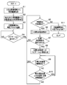
- 3 is a flowchart showing the operation of the endoscope system in the first embodiment.
- the flowchart which shows the automatic observation completed determination process in the endoscope system of the said Embodiment 1.
- FIG. The flowchart which shows the process of the target branch line setting in the endoscope system of the said Embodiment 1.
- FIG. 6 is a diagram showing a display example of a display screen of the display device in the first embodiment.
- the figure which shows the state in which the guidance arrow to the 1st small renal cup in the virtual endoscopic image is displayed in the said Embodiment 1.
- FIG. 1 The figure which shows the state in which the guidance arrow to the 2nd small renal cup in a virtual endoscopic image is displayed in the said Embodiment 1 after observation of the 1st small renal cup is complete
- the figure which shows a mode that the guidance of a navigation moves from the 1st small renal cup in a virtual endoscopic image to the 3rd small renal cup through a 2nd small renal cup.
- FIG. The figure which shows the example of the insertion auxiliary
- FIG. 1 to FIG. 11 show Embodiment 1 of the present invention and are diagrams showing a configuration of an endoscope system 1.
- the navigation system is applied to the endoscope system 1 and is configured to perform navigation when the subject is observed by the endoscope system 1.
- an endoscope system 1 to which a navigation system is applied includes an endoscope device 4 having an endoscope 2 and a camera control unit (CCU) 3, a position detection device 5, and a server 6. And an image processing device 7 and a display device 8.
- CCU camera control unit
- the endoscope 2 includes an elongated insertion portion 11 having flexibility, which is inserted into a subject, an operation portion 12 connected to a proximal end portion of the insertion portion 11, and a side surface of the operation portion 12. And an extended cable 13.
- the operation unit 12 is provided with a navigation button 12a for generating navigation display start instruction data for starting navigation display.
- the navigation button 12a also serves as a guidance start instruction unit to which a command for starting the generation of guidance information by the guidance information generation unit 34 described later is input.
- the navigation button 12a is not limited to being provided on the operation unit 12 of the endoscope 2.
- the navigation button 12a may be provided as a foot switch, or may be provided as a switch having another configuration.
- An imaging system 10 for imaging the inside of the subject is provided at the distal end of the insertion unit 11.
- the imaging system 10 includes an objective optical system that forms an optical image in the subject, and a CCD that photoelectrically converts the optical image formed by the objective optical system to generate an imaging signal.
- the endoscope 2 is connected to the CCU 3 via the cable 13, and the imaging signal captured by the imaging system 10 and the navigation display start instruction data input from the navigation button 12 a are transmitted to the CCU 3.
- the CCU 3 performs predetermined image processing on the imaging signal transmitted from the endoscope 2 to generate endoscope image data. Also, the CCU 3 receives navigation display start instruction data input from the navigation button 12a.
- a plurality of receiving coils (not shown) are provided at predetermined intervals from the distal end portion to the proximal end portion of the insertion portion 11 described above.
- the plurality of receiving coils output electrical signals in accordance with the magnetic field generated by the position detection device 5.
- the endoscope 2 is connected to the position detection device 5 via the cable 14, and each electric signal output from the reception coil is transmitted to the position detection device 5.
- the position detection device 5 as a position information acquisition unit is based on an electrical signal from a reception coil provided at the distal end portion of the insertion portion 11 among a plurality of reception coils, and at the distal end of the insertion portion 11 in the subject.
- the position information of the viewpoint of the imaging system 10 (this position information includes information on the three-dimensional position of the viewpoint and the line-of-sight direction of the viewpoint) is obtained by calculation.
- the acquisition of the position information by the position detection device 5 is repeatedly performed at regular time intervals, for example.
- the position detection device 5 calculates and acquires insertion shape data indicating the insertion shape of the insertion portion 11 based on the electrical signals from the plurality of reception coils described above.
- the curved shape data is acquired using the receiving coil.
- the present invention is not limited to this.
- the curved shape data is acquired using an FBG (Fiber Bragg Grating) sensor or the like. It doesn't matter.
- the CCU 3, the position detection device 5, and the server 6 described above are connected to the image processing device 7.
- the server 6 is connected to the image processing apparatus 7 via a communication line such as a hospital LAN.
- the CCU 3 transmits the endoscope image data generated as described above and the navigation display start instruction data received from the endoscope 2 to the image processing device 7.
- the position detection device 5 transmits viewpoint position information (position and direction data) and insertion shape data of the insertion unit 11 to the image processing device 7.
- the server 6 stores preoperative multi-slice image data 16a to 16n acquired in advance by CT, MRI, PET, or the like, for example, before performing the examination by the endoscope system 1. Then, the server 6 transmits these preoperative multi-slice image data 16a to 16n to the image processing device 7.
- the image processing apparatus 7 reads the preoperative multi-slice image data 16a to 16n from the server 6, but instead of this, a CD-ROM or the like in which the preoperative multi-slice image data 16a to 16n is stored can be used. Of course, it is possible to read from a portable recording medium.
- the image processing apparatus 7 creates image data by performing a process described later based on each data fetched from the CCU 3, the position detection apparatus 5, and the server 6.
- the image processing device 7 is connected to the display device 8, and the display device 8 receives and displays the image data created by the image processing device 7.
- the display device 8 is a display unit that displays a navigation image created by the image processing device 7 as will be described later.
- FIG. 2 is a block diagram showing a configuration of the image processing apparatus 7.
- the image processing device 7 includes an image information storage unit 21, an image processing unit 22, a viewpoint position storage unit 23, a registration unit 24, a coordinate conversion unit 25, a determination unit 26, and an input unit 27. ing.
- the image information storage unit 21 reads from the server 6 and stores preoperative multi-slice image data 16a to 16n, which are image information relating to a subject acquired in advance for constructing three-dimensional image information.
- the viewpoint position storage unit 23 stores the position information of the viewpoint acquired by the position detection device 5, and, as described above, for example, a plurality of points acquired by the position detection device 5 repeatedly at regular time intervals. It is possible to accumulate position information at the time.
- the alignment unit 24 includes real space coordinates describing the position information of the viewpoint acquired by the position detection device 5 and stored in the viewpoint position storage unit 23, and a predetermined extracted by the luminal organ extraction unit 31 as described later. Alignment with the 3D image coordinates describing the luminal organ.
- the alignment by the alignment unit 24 is performed, for example, as calculation of a conversion formula from real space coordinates to three-dimensional image coordinates.
- the alignment method is not limited to the method using the above-described conversion formula.
- the position detection of the feature points on the patient's body surface as disclosed in Japanese Patent Application Laid-Open No. 2005-31770 is possible.
- a registration method based on feature point designation on 3D image data, or by matching an endoscopic image and a virtual endoscopic image as disclosed in Japanese Patent Application Laid-Open No. 2009-279251 An alignment method or the like may be employed.
- the coordinate conversion unit 25 converts the position and direction data stored in the viewpoint position storage unit 23 into values on the three-dimensional data coordinates based on the conversion formula calculated by the alignment unit 24. Then, the coordinate conversion unit 25 stores the converted viewpoint position and direction data in the viewpoint position storage unit 23 in association with the position and direction data before conversion and the time stamp.
- the position information of the viewpoint acquired by the position detection device 5 as the position information acquisition unit is aligned with the three-dimensional image coordinate information of a predetermined luminal organ by the alignment unit 24 and the coordinate conversion unit 25.
- An alignment unit that generates correction position information is configured.
- the determination unit 26 observes the branch pipes based on the position information of the branch pipes extracted within a predetermined area by the branch pipe extraction unit 32 and the corrected correction position information as described later. The presence or absence of is determined. The determination unit 26 cumulatively stores the determination results of the determination unit 26 when the position indicated by the corrected position information received via the viewpoint position storage unit 23 is within the predetermined area described above. A portion 36 is provided. The determination unit 26 determines whether or not the branch pipe is observed every time position information is acquired at a constant time interval, and accumulates and stores the latest determination result in the determination result storage unit 36. It has become.
- the stored content of the determination result storage unit 36 is, for example, "Branch line 1: not observed, branch line 2: unobserved, ..., branch line n: not observed” ⁇ "Branch line 1: Not observed, Branch line 2: Observed, ..., Branch line n: Not observed” As the observation progresses, the observation state of each branch pipe is changed sequentially from “unobserved” to “observed”.
- the input unit 27 is used to input an operation to the image processing apparatus 7 and includes an area designating unit that can designate a predetermined area from which the branch pipe extraction unit 32 extracts a branch pipe. .
- the area specified by the area specifying unit is a predetermined area to be observed.
- the predetermined region can be arbitrarily designated with respect to the predetermined luminal organ extracted by the luminal organ extracting unit 31, and may be a part of the predetermined luminal organ or all of them. It does not matter.
- the image processing unit 22 includes a luminal organ extraction unit 31, a branch duct extraction unit 32, a target setting unit 33, and a guidance information generation unit 34.
- the luminal organ extraction unit 31 reads out the image information (preoperative multi-slice image data 16a to 16n) stored in the image information storage unit 21 to construct three-dimensional image information, and further determines predetermined information from the three-dimensional image information. Extract luminal organs.
- the luminal organ has a luminal structure of the kidney as an example.
- the luminal organ extraction unit 31 uses, as the luminal organ 51, for example, the ureter 52, the renal pelvis 53, the large renal cup 54, the small renal cup 55, and the renal papilla 56 (or, if necessary, the bladder and the urethra).
- a predetermined luminal organ is extracted (see FIG. 6).
- the branch line extraction unit 32 extracts a branch line existing in a predetermined region to be observed set by the input unit 27 from a predetermined lumen organ. In order to perform an inspection without any leakage, it is preferable that the branch pipe extraction unit 32 extracts all the branch pipes existing in a predetermined area.
- the target setting unit 33 sets one of the unobserved branch pipelines determined as unobserved by the determination unit 26 as the target branch pipeline.
- the setting of the target branch pipeline by the target setting unit 33 is performed based on the latest stored contents of the determination result storage unit 36 described above.
- the target setting unit 33 sets the unobserved branch pipe that is closest to the current viewpoint position indicated by the correction position information (preferably at the distal end side in the insertion direction of the insertion section 11) as the target branch pipe. To do.
- the target setting unit 33 is on the front side of the current viewpoint position indicated by the correction position information. If the current viewpoint position is not on the tip side, the target branch pipeline is updated based on the corrected position information. As will be described later, when the operator performs an operation that deviates from the navigation route, a new target branch pipeline is set based on the current viewpoint position so that appropriate navigation can always be performed. Because.
- the guidance information generation unit 34 changes the target branch pipeline to the target setting unit 33 and another one of the unobserved branch pipelines. While updating, guidance information to the target branch pipeline is generated. As a result, navigation to unobserved branch pipelines is performed one after another.
- the guidance information generation unit 34 insert the insertion unit 11 for all the extracted branch pipes? It is determined whether or not, and guidance information to all the branch pipes determined to be insertable is sequentially generated.
- the guidance information generation unit 34 may generate the guidance information at regular time intervals according to the acquisition of the positional information by the position detection device 5 that is repeatedly performed at regular time intervals as described above. Thereby, it becomes possible to display guidance information in real time.
- the navigation button 12a is a guidance start instruction unit to which a command to start generation of guidance information by the guidance information generation unit 34 is input.
- the guidance information generation unit 34 receives a command to the navigation button 12a.
- Guidance information is generated from the point in time. Therefore, when the surgeon considers that navigation is unnecessary and does not operate the navigation button 12a, no guidance information is generated, that is, it is not displayed on the display device 8.
- the image processing unit 22 superimposes the guidance information generated by the guidance information generation unit 34 on the virtual endoscopic image 42, the endoscope image 43, or the like to form a navigation image, and image data for display together with other display information Is output to the display device 8. As a result, a navigation image is displayed on the display device 8.
- FIG. 6 is a diagram showing a display example of the display screen 8a of the display device 8.
- the reference numerals in the image displayed on the display screen 8a in FIG. 6 are used as appropriate.
- an overhead image 41, a virtual endoscopic image 42, and an endoscopic image 43 are displayed on the display screen 8 a of the display device 8.
- the bird's-eye view image 41 is a two-dimensional image of the luminal organ observed stereoscopically when the luminal organ constructed as the three-dimensional image data is looked down on.
- the virtual endoscopic image 42 is a two-dimensional image when a luminal organ constructed as three-dimensional image data is observed from the viewpoint position of the imaging system 10.
- the endoscopic image 43 is a captured image captured by the imaging system 10. Note that the display example shown in FIG. 6 is merely an example, and other information may be displayed or some information may be omitted.
- the ureter 52, renal pelvis 53, large renal cup 54, small renal cup 55, and renal papilla 56 in the luminal organ 51 are displayed.
- An insertion portion image 61 showing the insertion shape is displayed.
- the tip of the insertion portion image 61 is the current viewpoint position 60.
- the current viewpoint position 60 is in the great kidney cup 54.
- the endoscopic image 43 shown in FIG. 6 shows the openings of a plurality of small renal cups 55 observed from the large renal cup 54 corresponding to the viewpoint position 60 of the current imaging system 10 in the large renal cup 54. Is displayed.
- the virtual endoscopic image 42 displays openings of a plurality of small kidney cups 55 that should be observed from the viewpoint position 60 of the current imaging system 10.
- FIG. 3 is a flowchart showing the operation of the endoscope system 1.
- the image processing apparatus 7 accesses the server 6 to read preoperative multi-slice image data 16a to 16n and store them in the image information storage unit 21. Then, the luminal organ extraction unit 31 constructs 3D image information from the preoperative multi-slice image data 16a to 16n stored in the image information storage unit 21, and further, a predetermined luminal organ from the constructed 3D image information. Is extracted (step S1).
- the branch channel extraction unit 32 selects a branch channel existing in a predetermined region to be observed set by the input unit 27 from the predetermined lumen organ extracted by the lumen organ extraction unit 31. Further extraction is performed (step S2).
- step S3 the automatic observation determination process shown in FIG. 4 is started.
- FIG. 4 is a flowchart showing an automatic observation completion determination process in the endoscope system.
- the latest viewpoint position information is acquired from the position detection device 5 and stored in the viewpoint position storage unit 23 (step S21).
- the acquired latest viewpoint position information is aligned with the three-dimensional image coordinate information by the alignment unit 24 and the coordinate conversion unit 25 to generate corrected position information (step S22).
- the determination unit 26 determines whether or not the branch pipe in the predetermined area to be observed has been observed (step S23).
- step S24 the determination result is cumulatively stored in the determination result storage unit 36 as described above (step S24), and it is determined whether or not to end this process based on whether or not a process end signal has been received (step S24). Step S25).
- step S21 If it is determined that the process has not been completed yet, the process returns to step S21 to obtain the next latest viewpoint position information and perform the above-described processing. Finish.
- the determination result storage unit 36 stores the latest information on whether each branch pipe in the predetermined area has been observed or not observed. .
- step S3 after starting the automatic observation completed determination process in step S3, it waits for the navigation button 12a to be operated to turn on the navigation display (step S4).
- step S4 while waiting for an operation to turn on the navigation display, the automatic observation completion determination process started in step S3 continues to be executed in parallel as described above.
- step S4 when it is determined in step S4 that the navigation display is turned on, based on the latest determination result of the automatic observation completion determination process stored in the determination result storage unit 36, a predetermined area to be observed is determined. It is determined whether or not there is an unobserved branch pipe (step S5).
- step S6 when it is determined that an unobserved branch pipe exists, a target branch pipe setting process is performed (step S6).
- FIG. 5 is a flowchart showing a process of setting a target branch line in the endoscope system 1.
- the distal end side here is a direction that is a path that pulls the endoscope 2 back to the proximal end side of the endoscope 2 when the path to the unobserved branch duct is traced along the branch duct of the lumen. Instead, a direction that is a path for advancing the endoscope 2 toward the distal end side of the current endoscope 2 is shown.
- Step S32 when it is determined that an unobserved branch pipe exists on the tip side from the current viewpoint position, the closest unobserved branch pipe located on the tip side from the current viewpoint position is selected.
- step S31 when it is determined that there is no unobserved branch pipe on the tip side of the current viewpoint position, the unobserved branch located closest to the current viewpoint position except for the tip side.
- the pipeline is selected as the selected branch pipeline (step S33). The closeness at this time is determined by the distance of the route along the branch pipe.
- step S32 or step S33 it is determined whether or not the inner diameter of the selected branch pipe selected in step S32 or step S33 is equal to or larger than the outer diameter of the insertion section 11, that is, whether or not the insertion section 11 can be inserted (step). S34).
- the selected branch pipeline is set as the target branch pipeline for navigation (step S35).
- step S34 If it is determined in step S34 that the insertion is impossible, the selected branch pipe is excluded from the target branch pipe selection targets (step S36).
- step S35 or step S36 the process returns to the process shown in FIG.
- step S7 determines whether or not the target branch pipe has been set in step S6 (step S7). That is, as described above, if the process of step S35 is performed, the target branch pipe is set, and if the process of step S36 is performed, the target branch pipe is not yet set. For this reason, this determination is made here.
- step S5 determines whether an unobserved branch pipe exists. This process is performed again to reset the target branch pipeline.
- step S8 If it is determined in step S7 that the target branch pipeline is set, navigation information for guiding the target branch pipeline from the current viewpoint position is generated (step S8).
- step S9 based on the latest determination result stored in the determination result storage unit 36, it is determined whether or not the target branch pipe has been observed.
- step S5 if it is determined that the target branch pipe has been observed, the process returns to step S5 and the above-described process is repeated.
- step S10 it is determined whether or not the position of the target branch pipe is closer to the tip than the current viewpoint position. This is because when the surgeon inserts the insertion portion 11 according to the navigation, the position of the target branch conduit should be on the tip side from the current viewpoint position, but the surgeon performs an operation that deviates from the navigation path. In this case, for example, when the insertion portion 11 is inserted into a branch pipe different from the target branch pipe indicated by the navigation, the position of the target branch pipe should not be on the tip side with respect to the current viewpoint position. There is also. This step S10 is a determination for identifying such a case.
- step S9 if it is determined that the position is closer to the tip than the current viewpoint position, the process returns to step S9 and waits for the target branch pipe to be observed.
- step S10 determines that the position is not the tip side from the current viewpoint position, in order to reset a more appropriate target branch pipeline based on the current viewpoint position, in step S5 described above, Return to processing.
- step S5 when it is determined in step S5 that there are no unobserved branch lines in the predetermined area, that is, all the branch lines in the predetermined area have been observed.
- This process is terminated after the process is terminated (step S11), for example, by transmitting a process end signal to the automatically observed determination process started in step S11.
- FIG. 7 is a diagram showing a state in which a guide arrow 62 to the first small kidney cup 55a in the virtual endoscopic image 42 is displayed, and FIG. 8 shows the observation of the first small kidney cup 55a.
- FIG. 9 is a diagram showing a state in which a guide arrow 62 to the second small kidney cup 55b in the virtual endoscopic image 42 is displayed after the completion, and FIG. 9 shows the first small small image in the virtual endoscopic image 42 It is a figure which shows a mode that the guidance of navigation moves from the renal cup 55a to the 3rd small renal cup 55c through the 2nd small renal cup 55b.
- the viewpoint position 60 of the current imaging system 10 is in the large kidney cup 54, and from this viewpoint position 60, the virtual endoscopic image 42 or the endoscopic image is displayed. Assume that three small kidney cups 55 are observed as shown at 43.
- the first small renal cup 55a which is the closest unobserved branch pipe located on the tip side of the current viewpoint position 60, is set as the target branch pipe, and the target branch is obtained.
- a guide arrow 62 is displayed in the virtual endoscopic image 42, for example.
- the guide arrow 62 starts from the center position of the virtual endoscopic image 42 corresponding to the current viewpoint position 60, and ends at the first small renal cup 55a that is the target branch conduit. It is an arrow in the direction.
- the guide arrow 62 shown in FIG. 7 (and FIG. 8) is an example of the navigation display and is not limited to this display mode, and other modes of navigation display may be used.
- the first small renal cup 55a When the observation of the first small renal cup 55a is completed in this way, the first small renal cup 55a is already observed, and is therefore the closest unobserved branch line on the distal end side relative to the current viewpoint position 60.
- the second small renal cup 55b is set as the next target branch conduit, and a guidance arrow 62 as shown in FIG. 8 is displayed as navigation to the second small renal cup 55b that has become the target branch conduit. .
- the guidance by the navigation display is, for example, from the first small renal cup 55a to the second small renal cup 55b in the order closer to the inside of the unobserved branch pipe located on the distal side than the current viewpoint position 60.
- the third small kidney cup 55c is moved in order.
- FIG. 10 is a diagram illustrating an example in which a guide arrow 62 is displayed in the endoscopic image 43.
- the navigation display may be performed on the overhead image 41 without being limited thereto.
- FIG. 11 is a diagram showing an example of an auxiliary insertion image displaying the target position mark 63 and the insertion impossible mark 64.
- an insertion auxiliary image is displayed by displaying a target position mark 63 and an insertion impossible mark 64 in the overhead view image 41.
- the target position mark 63 is a mark indicating the current position of the target branch pipe set by the process of step S35 described above.
- the insertion impossible mark 64 is a mark indicating the position of the branch pipe that has been excluded from the target branch pipe selection targets by the process of step S36 described above.
- the auxiliary insertion information such as the target position mark 63 and the non-insertable mark 64 may be displayed on the virtual endoscopic image 42 and the endoscopic image 43.
- the target branch pipelines determined to be unobserved when one of the unobserved branch pipelines determined to be unobserved is set as the target branch pipeline, and it is determined that the target branch pipeline has been observed. Since the guidance information to the target branch pipeline is generated while updating the target branch pipeline to another one of the unobserved branch pipelines, the target branch pipelines are sequentially switched to a plurality of lumen organs. The insertion operation is assisted, and it is possible to easily perform an inspection without any leakage.
- the input unit 27 which is an area designating unit capable of designating a predetermined area from which the branch pipe is to be extracted is further provided, a desired area can be set as an inspection target.
- the observation order is optimized and the movement amount of the insertion unit 11 is reduced. Inspection time can be shortened and inspection efficiency can be improved.
- the observation order can be optimized by setting the closest unobserved branch pipe at the tip of the current viewpoint position as the target branch pipe.
- the optimal target branch pipeline at that time can be set at any time, and appropriate navigation is always performed. Can be done.
- the determination result of whether or not the observation has been completed is cumulatively stored, and the target branch pipeline is set based on the latest stored content. It is not necessary to determine whether or not the branch pipe has been observed every time the pipe is set, so that the processing load can be reduced and the processing time can be shortened.
- the guidance information generation unit 34 since the guidance information generation unit 34 generates the guidance information from the time when a command is input to the navigation button 12a which is a guidance start instruction unit, the operator turns navigation display on / off at a desired timing. Can be switched.
- the navigation system has been mainly described. However, an operation method for operating the navigation system as described above may be used. It may be a non-temporary recording medium that can be read by the above.
- the present invention is not limited to the above-described embodiment as it is, and can be embodied by modifying the constituent elements without departing from the scope of the invention in the implementation stage.
- various aspects of the invention can be formed by appropriately combining a plurality of components disclosed in the embodiment. For example, you may delete some components from all the components shown by embodiment.
- the constituent elements over different embodiments may be appropriately combined.
Abstract
Description
図1から図11は本発明の実施形態1を示したものであり、内視鏡システム1の構成を示す図である。本実施形態は、ナビゲーションシステムを内視鏡システム1に適用したものとなっており、内視鏡システム1により被検体を観察する際のナビゲーションを行うものとして構成されている。 [Embodiment 1]
FIG. 1 to FIG. 11 show Embodiment 1 of the present invention and are diagrams showing a configuration of an endoscope system 1. In the present embodiment, the navigation system is applied to the endoscope system 1 and is configured to perform navigation when the subject is observed by the endoscope system 1.
「分岐管路1:未観察、 分岐管路2:未観察、 …、分岐管路n:未観察 」
→「分岐管路1:未観察、 分岐管路2:観察済み、…、分岐管路n:未観察 」
などのようになり、観察が進むにつれて、各分岐管路の観察状態が「未観察」から「観察済み」へと順次変化していくことになる。 The
"Branch line 1: not observed, branch line 2: unobserved, ..., branch line n: not observed"
→ "Branch line 1: Not observed, Branch line 2: Observed, ..., Branch line n: Not observed"
As the observation progresses, the observation state of each branch pipe is changed sequentially from “unobserved” to “observed”.
Claims (8)
- 予め取得した被検体に関する画像情報を記憶する画像情報記憶部と、
前記画像情報から所定の管腔臓器を抽出する管腔臓器抽出部と、
前記所定の管腔臓器から所定の領域内に存在する分岐管路を抽出する分岐管路抽出部と、
前記被検体内における視点の位置情報を取得する位置情報取得部と、
前記位置情報取得部で取得された前記視点の位置情報を前記所定の管腔臓器の3次元画像座標情報に位置合わせした補正位置情報を生成する位置合わせ部と、
前記補正位置情報に基づき前記分岐管路の観察の有無を判定する判定部と、
前記判定部により未観察であると判定された未観察分岐管路の1つを目標分岐管路として設定する目標設定部と、
前記目標分岐管路が観察済みであると前記判定部により判定された場合には、前記目標設定部に前記目標分岐管路を、前記未観察分岐管路の他の1つに更新させながら、前記目標分岐管路への誘導情報を生成する誘導情報生成部と、
を具備することを特徴とするナビゲーションシステム。 An image information storage unit for storing image information related to the subject acquired in advance;
A luminal organ extracting unit for extracting a predetermined luminal organ from the image information;
A branch line extraction unit for extracting a branch line existing in a predetermined region from the predetermined luminal organ;
A position information acquisition unit that acquires position information of a viewpoint in the subject;
An alignment unit that generates corrected position information in which the position information of the viewpoint acquired by the position information acquisition unit is aligned with the three-dimensional image coordinate information of the predetermined luminal organ;
A determination unit that determines whether or not the branch pipe is observed based on the correction position information;
A target setting unit that sets one of the unobserved branch pipelines determined as unobserved by the determination unit as a target branch pipeline;
If the determination unit determines that the target branch pipeline has been observed, the target setting unit updates the target branch pipeline to another one of the unobserved branch pipelines, A guidance information generator for generating guidance information to the target branch pipe;
A navigation system comprising: - 前記分岐管路抽出部は、前記所定の領域内に存在する分岐管路を全て抽出し、
前記誘導情報生成部は、前記分岐管路抽出部によって抽出された全ての分岐管路について挿入部を挿入可能か否かを判定して、挿入可能であると判定した全ての分岐管路への誘導情報を順次生成することを特徴とする請求項1に記載のナビゲーションシステム。 The branch pipe extraction unit extracts all branch pipes existing in the predetermined area,
The guidance information generation unit determines whether or not an insertion unit can be inserted for all branch pipelines extracted by the branch pipeline extraction unit, and determines to all branch pipelines determined to be insertable. The navigation system according to claim 1, wherein the guidance information is sequentially generated. - 前記分岐管路抽出部により前記分岐管路を抽出する対象となる前記所定の領域を指定可能な領域指定部をさらに具備したことを特徴とする請求項1に記載のナビゲーションシステム。 The navigation system according to claim 1, further comprising an area designating unit capable of designating the predetermined area as a target for extracting the branch pipe by the branch pipe extracting unit.
- 前記目標設定部は、前記補正位置情報により示される現在の視点位置に最も近い前記未観察分岐管路を前記目標分岐管路として設定することを特徴とする請求項1に記載のナビゲーションシステム。 The navigation system according to claim 1, wherein the target setting unit sets the unobserved branch pipe closest to the current viewpoint position indicated by the correction position information as the target branch pipe.
- 前記目標設定部は、前記補正位置情報により示される現在の視点位置に、挿入部の挿入方向の先端側において最も近い前記未観察分岐管路を前記目標分岐管路として設定するものであり、
該目標設定部は、前記目標分岐管路が未観察であると前記判定部により判定されているときに、該目標分岐管路が前記補正位置情報により示される現在の視点位置よりも先端側であるか否かを判定して、現在の視点位置よりも先端側でない場合には、前記補正位置情報に基づいて前記目標分岐管路を更新することを特徴とする請求項4に記載のナビゲーションシステム。 The target setting unit sets the unobserved branch pipe closest to the current viewpoint position indicated by the correction position information on the distal end side in the insertion direction of the insertion section as the target branch pipe.
When the determination unit determines that the target branch pipeline has not been observed, the target setting unit is located on the distal side of the current viewpoint position indicated by the correction position information. 5. The navigation system according to claim 4, wherein it is determined whether the target branch pipe is updated based on the correction position information when it is determined whether or not there is a tip side from the current viewpoint position. . - 前記補正位置情報により示される位置が前記所定の領域内であるときの、前記判定部の判定結果を累積的に記憶する判定結果記憶部をさらに具備し、
前記目標設定部は、前記判定結果記憶部の最新の記憶内容に基づき、前記目標分岐管路を設定することを特徴とする請求項1に記載のナビゲーションシステム。 A determination result storage unit that cumulatively stores the determination result of the determination unit when the position indicated by the correction position information is within the predetermined region;
The navigation system according to claim 1, wherein the target setting unit sets the target branch pipeline based on the latest stored contents of the determination result storage unit. - 前記誘導情報生成部による前記誘導情報の生成を開始させる命令が入力される誘導開始指示部をさらに具備し、
前記誘導情報生成部は、前記誘導開始指示部に前記命令が入力された時点から前記誘導情報を生成することを特徴とする請求項1に記載のナビゲーションシステム。 A guidance start instruction unit for inputting a command to start generation of the guidance information by the guidance information generation unit;
The navigation system according to claim 1, wherein the guidance information generation unit generates the guidance information from the time when the command is input to the guidance start instruction unit. - 画像情報記憶部と、管腔臓器抽出部と、分岐管路抽出部と、位置情報取得部と、位置合わせ部と、判定部と、目標設定部と、誘導情報生成部と、を具備するナビゲーションシステムの作動方法であって、
前記画像情報記憶部が、予め取得した被検体に関する画像情報を記憶し、
前記管腔臓器抽出部が、前記画像情報から所定の管腔臓器を抽出し、
前記分岐管路抽出部が、前記所定の管腔臓器から所定の領域内に存在する分岐管路を抽出し、
前記位置情報取得部が、前記被検体内における視点の位置情報を取得し、
前記位置合わせ部が、前記位置情報取得部で取得された前記視点の位置情報を前記所定の管腔臓器の3次元画像座標情報に位置合わせした補正位置情報を生成し、
前記判定部が、前記補正位置情報に基づき前記分岐管路の観察の有無を判定し、
前記目標設定部が、前記判定部により未観察であると判定された未観察分岐管路の1つを目標分岐管路として設定し、
前記目標分岐管路が観察済みであると前記判定部により判定された場合には、前記誘導情報生成部が、前記目標設定部に前記目標分岐管路を、前記未観察分岐管路の他の1つに更新させながら、前記目標分岐管路への誘導情報を生成することを特徴とするナビゲーションシステムの作動方法。 Navigation comprising: an image information storage unit; a luminal organ extraction unit; a branch duct extraction unit; a position information acquisition unit; a registration unit; a determination unit; a target setting unit; and a guidance information generation unit A method of operating the system,
The image information storage unit stores image information related to a subject acquired in advance,
The luminal organ extraction unit extracts a predetermined luminal organ from the image information,
The branch duct extraction unit extracts a branch duct existing in a predetermined region from the predetermined lumen organ;
The position information acquisition unit acquires position information of a viewpoint in the subject;
The alignment unit generates corrected position information in which the position information of the viewpoint acquired by the position information acquisition unit is aligned with the three-dimensional image coordinate information of the predetermined luminal organ,
The determination unit determines the presence or absence of observation of the branch pipe based on the correction position information,
The target setting unit sets one of the unobserved branch pipelines determined as unobserved by the determination unit as a target branch pipeline;
When the determination unit determines that the target branch pipeline has been observed, the guidance information generation unit transfers the target branch pipeline to the target setting unit, and other unobserved branch pipelines. A navigation system operating method, characterized in that guidance information to the target branch pipeline is generated while updating to one.
Priority Applications (4)
| Application Number | Priority Date | Filing Date | Title |
|---|---|---|---|
| JP2016520715A JP6038405B2 (en) | 2014-07-15 | 2015-04-28 | Navigation system and navigation system operating method |
| EP15822560.7A EP3153090A1 (en) | 2014-07-15 | 2015-04-28 | Navigation system and navigation system operation method |
| CN201580037250.5A CN106659365B (en) | 2014-07-15 | 2015-04-28 | Navigation system, the working method of navigation system |
| US15/402,634 US10918443B2 (en) | 2014-07-15 | 2017-01-10 | Navigation system and operation method of navigation system |
Applications Claiming Priority (2)
| Application Number | Priority Date | Filing Date | Title |
|---|---|---|---|
| JP2014145312 | 2014-07-15 | ||
| JP2014-145312 | 2014-07-15 |
Related Child Applications (1)
| Application Number | Title | Priority Date | Filing Date |
|---|---|---|---|
| US15/402,634 Continuation US10918443B2 (en) | 2014-07-15 | 2017-01-10 | Navigation system and operation method of navigation system |
Publications (1)
| Publication Number | Publication Date |
|---|---|
| WO2016009701A1 true WO2016009701A1 (en) | 2016-01-21 |
Family
ID=55078205
Family Applications (1)
| Application Number | Title | Priority Date | Filing Date |
|---|---|---|---|
| PCT/JP2015/062831 WO2016009701A1 (en) | 2014-07-15 | 2015-04-28 | Navigation system and navigation system operation method |
Country Status (5)
| Country | Link |
|---|---|
| US (1) | US10918443B2 (en) |
| EP (1) | EP3153090A1 (en) |
| JP (1) | JP6038405B2 (en) |
| CN (1) | CN106659365B (en) |
| WO (1) | WO2016009701A1 (en) |
Cited By (3)
| Publication number | Priority date | Publication date | Assignee | Title |
|---|---|---|---|---|
| JP2019097661A (en) * | 2017-11-29 | 2019-06-24 | 水野 裕子 | Endoscope navigation device |
| JP2019097665A (en) * | 2017-11-29 | 2019-06-24 | 水野 裕子 | Endoscope apparatus |
| WO2021145265A1 (en) * | 2020-01-17 | 2021-07-22 | 富士フイルム株式会社 | Medical image processing device, endoscope system, diagnosis assistance method, and program |
Families Citing this family (1)
| Publication number | Priority date | Publication date | Assignee | Title |
|---|---|---|---|---|
| CN115624308B (en) * | 2022-12-21 | 2023-07-07 | 深圳市资福医疗技术有限公司 | Capsule endoscope cruise control method, device and storage medium |
Citations (3)
| Publication number | Priority date | Publication date | Assignee | Title |
|---|---|---|---|---|
| JP2004089483A (en) * | 2002-08-30 | 2004-03-25 | Olympus Corp | Endoscope apparatus |
| WO2007129493A1 (en) * | 2006-05-02 | 2007-11-15 | National University Corporation Nagoya University | Medical image observation support device |
| JP5378628B1 (en) * | 2012-03-06 | 2013-12-25 | オリンパスメディカルシステムズ株式会社 | Endoscope system |
Family Cites Families (8)
| Publication number | Priority date | Publication date | Assignee | Title |
|---|---|---|---|---|
| JP4343723B2 (en) | 2004-01-30 | 2009-10-14 | オリンパス株式会社 | Insertion support system |
| JP4537756B2 (en) | 2004-04-30 | 2010-09-08 | オリンパス株式会社 | Ultrasonic diagnostic equipment |
| US7907991B2 (en) | 2005-03-02 | 2011-03-15 | C. R. Bard, Inc. | System and method for marking body cavities |
| JP5188879B2 (en) | 2008-05-23 | 2013-04-24 | オリンパスメディカルシステムズ株式会社 | Medical equipment |
| JP5372407B2 (en) * | 2008-05-23 | 2013-12-18 | オリンパスメディカルシステムズ株式会社 | Medical equipment |
| JP2011189074A (en) | 2010-03-16 | 2011-09-29 | Olympus Medical Systems Corp | Medical device |
| JP6013037B2 (en) * | 2011-06-23 | 2016-10-25 | 東芝メディカルシステムズ株式会社 | Medical image processing device |
| JP5947707B2 (en) * | 2012-12-27 | 2016-07-06 | 富士フイルム株式会社 | Virtual endoscopic image display apparatus and method, and program |
-
2015
- 2015-04-28 JP JP2016520715A patent/JP6038405B2/en active Active
- 2015-04-28 EP EP15822560.7A patent/EP3153090A1/en not_active Withdrawn
- 2015-04-28 CN CN201580037250.5A patent/CN106659365B/en active Active
- 2015-04-28 WO PCT/JP2015/062831 patent/WO2016009701A1/en active Application Filing
-
2017
- 2017-01-10 US US15/402,634 patent/US10918443B2/en active Active
Patent Citations (3)
| Publication number | Priority date | Publication date | Assignee | Title |
|---|---|---|---|---|
| JP2004089483A (en) * | 2002-08-30 | 2004-03-25 | Olympus Corp | Endoscope apparatus |
| WO2007129493A1 (en) * | 2006-05-02 | 2007-11-15 | National University Corporation Nagoya University | Medical image observation support device |
| JP5378628B1 (en) * | 2012-03-06 | 2013-12-25 | オリンパスメディカルシステムズ株式会社 | Endoscope system |
Cited By (4)
| Publication number | Priority date | Publication date | Assignee | Title |
|---|---|---|---|---|
| JP2019097661A (en) * | 2017-11-29 | 2019-06-24 | 水野 裕子 | Endoscope navigation device |
| JP2019097665A (en) * | 2017-11-29 | 2019-06-24 | 水野 裕子 | Endoscope apparatus |
| WO2021145265A1 (en) * | 2020-01-17 | 2021-07-22 | 富士フイルム株式会社 | Medical image processing device, endoscope system, diagnosis assistance method, and program |
| JP7289373B2 (en) | 2020-01-17 | 2023-06-09 | 富士フイルム株式会社 | Medical image processing device, endoscope system, diagnosis support method and program |
Also Published As
| Publication number | Publication date |
|---|---|
| US10918443B2 (en) | 2021-02-16 |
| CN106659365A (en) | 2017-05-10 |
| US20170112578A1 (en) | 2017-04-27 |
| JPWO2016009701A1 (en) | 2017-04-27 |
| CN106659365B (en) | 2019-09-06 |
| JP6038405B2 (en) | 2016-12-07 |
| EP3153090A1 (en) | 2017-04-12 |
Similar Documents
| Publication | Publication Date | Title |
|---|---|---|
| JP5718537B2 (en) | Endoscope system | |
| JP5160699B2 (en) | Medical equipment | |
| JP3850217B2 (en) | Endoscope position detector for bronchi | |
| JP5945643B2 (en) | Endoscope system and operation method of endoscope system | |
| JP6038405B2 (en) | Navigation system and navigation system operating method | |
| JP4153963B2 (en) | Endoscope insertion shape detection device | |
| US10388066B2 (en) | Controlled perspective guidance method | |
| EP2430979B1 (en) | Biopsy support system | |
| JP2005278888A (en) | Procedure support system | |
| US20180235716A1 (en) | Insertion unit support system | |
| US10085705B2 (en) | Medical observation system | |
| JP5613353B2 (en) | Medical equipment | |
| WO2019198322A1 (en) | Medical treatment system | |
| JP4445792B2 (en) | Insertion support system | |
| US20230123739A1 (en) | Image guidance during cannulation | |
| JP4190454B2 (en) | Insertion support device |
Legal Events
| Date | Code | Title | Description |
|---|---|---|---|
| 121 | Ep: the epo has been informed by wipo that ep was designated in this application |
Ref document number: 15822560 Country of ref document: EP Kind code of ref document: A1 |
|
| ENP | Entry into the national phase |
Ref document number: 2016520715 Country of ref document: JP Kind code of ref document: A |
|
| REEP | Request for entry into the european phase |
Ref document number: 2015822560 Country of ref document: EP |
|
| WWE | Wipo information: entry into national phase |
Ref document number: 2015822560 Country of ref document: EP |
|
| NENP | Non-entry into the national phase |
Ref country code: DE |