WO2021144918A1 - 回転電機装置および電動パワーステアリング装置 - Google Patents
回転電機装置および電動パワーステアリング装置 Download PDFInfo
- Publication number
- WO2021144918A1 WO2021144918A1 PCT/JP2020/001276 JP2020001276W WO2021144918A1 WO 2021144918 A1 WO2021144918 A1 WO 2021144918A1 JP 2020001276 W JP2020001276 W JP 2020001276W WO 2021144918 A1 WO2021144918 A1 WO 2021144918A1
- Authority
- WO
- WIPO (PCT)
- Prior art keywords
- rotary electric
- capacitor
- electric machine
- smoothing capacitor
- smoothing
- Prior art date
Links
Images


Classifications
-
- H—ELECTRICITY
- H02—GENERATION; CONVERSION OR DISTRIBUTION OF ELECTRIC POWER
- H02K—DYNAMO-ELECTRIC MACHINES
- H02K11/00—Structural association of dynamo-electric machines with electric components or with devices for shielding, monitoring or protection
- H02K11/30—Structural association with control circuits or drive circuits
- H02K11/33—Drive circuits, e.g. power electronics
-
- H—ELECTRICITY
- H02—GENERATION; CONVERSION OR DISTRIBUTION OF ELECTRIC POWER
- H02K—DYNAMO-ELECTRIC MACHINES
- H02K11/00—Structural association of dynamo-electric machines with electric components or with devices for shielding, monitoring or protection
- H02K11/30—Structural association with control circuits or drive circuits
-
- H—ELECTRICITY
- H02—GENERATION; CONVERSION OR DISTRIBUTION OF ELECTRIC POWER
- H02K—DYNAMO-ELECTRIC MACHINES
- H02K3/00—Details of windings
- H02K3/46—Fastening of windings on the stator or rotor structure
- H02K3/50—Fastening of winding heads, equalising connectors, or connections thereto
-
- B—PERFORMING OPERATIONS; TRANSPORTING
- B62—LAND VEHICLES FOR TRAVELLING OTHERWISE THAN ON RAILS
- B62D—MOTOR VEHICLES; TRAILERS
- B62D5/00—Power-assisted or power-driven steering
- B62D5/04—Power-assisted or power-driven steering electrical, e.g. using an electric servo-motor connected to, or forming part of, the steering gear
-
- H—ELECTRICITY
- H02—GENERATION; CONVERSION OR DISTRIBUTION OF ELECTRIC POWER
- H02K—DYNAMO-ELECTRIC MACHINES
- H02K2203/00—Specific aspects not provided for in the other groups of this subclass relating to the windings
- H02K2203/09—Machines characterised by wiring elements other than wires, e.g. bus rings, for connecting the winding terminations
Definitions
- the present application relates to a rotary electric machine and an electric power steering device.
- a stator, a rotor, etc. are built in the case of the rotary electric machine, and control units are assembled in a laminated manner in the vicinity thereof. Structures are scattered. Further, there is a power module having a built-in switching element for supplying an electric current to a rotary electric machine and a control board having a structure in which the control board is upright in parallel with the axial direction of the output shaft (Patent Document 1).
- the conventional device disclosed in Patent Document 1 has a structure in which a control unit is integrated at a motor end (hereinafter referred to as a counter-output side) opposite to the output side of the motor output shaft.
- a control unit is integrated at a motor end (hereinafter referred to as a counter-output side) opposite to the output side of the motor output shaft.
- the control unit expands in the radial direction of the motor due to restrictions on mounting on the vehicle.
- the length of the motor in the output shaft direction is often acceptable even if it is relatively long. Therefore, the radial area of the control unit needs to be equal to or smaller than that of the motor.
- the power module and the control board are upright in parallel in the output axis direction, and are adjacent to the surface of the heat sink to supply electric power to the power module from the outside.
- a bus bar unit holding a bus bar is installed. Further, on the surface on which the bus bar unit is mounted, a plurality of smoothing capacitors that smooth the drive power supplied from the external power source to reduce noise are mounted and electrically connected to the bus bar.
- Patent Document 1 does not mention the holding structure of the smoothing capacitor.
- the smoothing capacitor When the smoothing capacitor is held only at the connection between the terminal of the smoothing capacitor and the bus bar, the smoothing capacitor vibrates significantly when an impact or vibration is applied to the electric power steering device, resulting in deterioration of the connection between the terminal and the bus bar. There is a concern that a connection failure of the smoothing capacitor may occur. Therefore, it is necessary to realize a structure that maintains and maintains high vibration resistance of the smoothing capacitor without deteriorating the assembling property.
- Patent Document 1 describes a motor, that is, an electric machine, the same can be said for a rotary electric machine including an electric machine and a generator.
- the rotary electric machine according to the present application is a rotary electric device in which a control device and a rotary electric machine are integrated, and an object of the present invention is to provide a device having high vibration resistance and excellent product assembly. Another object of the present invention is to obtain an electric power steering device equipped with a rotary electric device having high vibration resistance and excellent product assembly.
- the rotary electric device is A rotary electric machine with a winding and an output shaft, A power module with a switching element connected to the winding,
- the bus bar which is held in the bus bar holder and constitutes the power supply path to the power module,
- With multiple smoothing capacitors connected to the busbar It is provided with a capacitor holder in which a plurality of smoothing capacitors are arranged in the axial direction of the rotary electric machine on the radial side of the rotary electric machine and held from the outer peripheral side of the rotary electric machine.
- the electric power steering device is provided with the above-mentioned rotary electric machine.
- the rotary electric machine device and the electric power steering device According to the rotary electric machine device and the electric power steering device according to the present application, it is possible to provide a device having high vibration resistance and excellent product assembly.
- FIG. It is a circuit diagram of the rotary electric machine device which concerns on Embodiment 1.
- FIG. It is sectional drawing of the rotary electric machine device which concerns on Embodiment 1.
- FIG. It is a perspective view of the top view of the rotary electric machine which concerns on Embodiment 1.
- FIG. It is an inside external view of the capacitor holder of the rotary electric machine which concerns on Embodiment 1.
- FIG. It is an outside external view of the capacitor holder of the rotary electric machine which concerns on Embodiment 1.
- FIG. It is an inside external view which attached the capacitor to the capacitor holder of the rotary electric machine which concerns on Embodiment 1.
- FIG. It is an outside external view which attached the capacitor to the capacitor holder of the rotary electric machine which concerns on Embodiment 1.
- FIG. It is an outside external view which attached the capacitor to the capacitor holder of the rotary electric machine which concerns on Embodiment 1.
- FIG. It is an outside external view which attached the capacitor to the capacitor holder of the
- FIG. It is an external view of the inside of the snap fit part of the capacitor holder of the rotary electric machine which concerns on Embodiment 1. It is an external view of the bus bar holder of the rotary electric machine which concerns on Embodiment 1.
- FIG. It is a circuit diagram of the rotary electric machine device which concerns on Embodiment 2.
- FIG. It is sectional drawing of the rotary electric machine device which concerns on Embodiment 2.
- FIG. It is a perspective view of the top view of the rotary electric machine which concerns on Embodiment 2.
- FIG. It is sectional drawing of the rotary electric machine device which concerns on Embodiment 3.
- FIG. It is a perspective view of the top view of the rotary electric machine which concerns on Embodiment 3.
- FIG. It is a perspective view of the top view of the rotary electric machine which concerns on Embodiment 3.
- FIG. 1 It is an inside external view of the capacitor holder of the rotary electric machine which concerns on Embodiment 3.
- FIG. It is an outside external view of the capacitor holder of the rotary electric machine which concerns on Embodiment 3.
- FIG. It is an inside external view which attached the smoothing capacitor to the capacitor holder of the rotary electric machine which concerns on Embodiment 3.
- FIG. It is an outside external view which attached the smoothing capacitor to the capacitor holder of the rotary electric machine which concerns on Embodiment 3.
- FIG. It is an external view of the bus bar holder of the rotary electric machine which concerns on Embodiment 3.
- FIG. It is a block diagram of the electric power steering apparatus which concerns on Embodiment 4.
- FIG. 4 It is an inside external view of the capacitor holder of the rotary electric machine which concerns on Embodiment 3.
- FIG. 1 is a circuit diagram of the rotary electric machine device 100 according to the first embodiment.
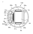
- FIG. 2 is a cross-sectional view of the rotary electric machine device 100 according to the first embodiment.
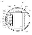
- FIG. 3 is a perspective view of the rotary electric machine 100 according to the first embodiment in a top view.
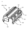
- FIG. 4 is an internal external view of the capacitor holders 44a and 44b of the rotary electric machine 100 according to the first embodiment.
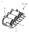
- FIG. 5 is an external external view of the capacitor holders 44a and 44b of the rotary electric machine 100 according to the first embodiment.
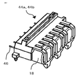
- FIG. 6 is an internal external view in which the smoothing capacitor 18 is attached to the capacitor holders 44a and 44b of the rotary electric machine 100 according to the first embodiment.
- FIG. 7 is an external external view in which the smoothing capacitor 18 is attached to the capacitor holders 44a and 44b of the rotary electric machine 100 according to the first embodiment.
- FIG. 8 is an external view of the inside of the snap-fit portion 59 of the capacitor holders 44a and 44b of the rotary electric machine 100 according to the first embodiment.
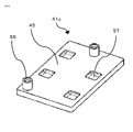
- FIG. 9 is an external view of the bus bar holders 41a and 41b of the rotary electric machine 100 according to the first embodiment.
- FIG. 1 is a circuit diagram of the rotary electric machine device 100.
- 1a and 1b are control units
- 2 is a rotary electric machine provided with two sets of three-phase windings. Since the control units 1a and 1b have the same configuration and substantially the same parts are mounted on the control units 1a and 1b, one of them will be described.
- the control unit 1a is mainly composed of a control circuit unit 4a equipped with a CPU 3a, a power module 5a having an inverter circuit for supplying a current to the rotary electric machine 2, a power supply relay switching element 6a, and a filter 7a.
- the power supply + B and GND are connected from the battery 8 mounted on the vehicle.
- the ignition switch 9 turns on the power via the power supply circuit 10a of the control circuit unit 4a. Further, for example, information such as a torque sensor for detecting the steering torque mounted near the steering wheel and a speed sensor for detecting the traveling speed of the vehicle is input from the sensors 11.
- the information from the sensors 11 is transmitted to the CPU 3a via the input circuit 12a of the control circuit unit 4a.
- the CPU 3a calculates and outputs a current value, which is a control amount for rotating the rotary electric machine 2, from the information.
- This output signal is transmitted to the power module 5a having an inverter circuit via the drive circuit 13a constituting the output circuit.
- the drive circuit 13a receives a command signal from the CPU 3a and outputs a drive signal for driving each switching element of the power module 5a.
- the drive circuit 13a Since the drive circuit 13a allows only a small current to flow, it is mounted on the control circuit unit 4a. However, it can also be arranged in the power module 5a.
- the power module 5a includes switching elements for the three-phase U winding, V winding, and W winding of the rotary electric machine 2.
- the power module 5a includes switching elements 16Ua, 14V, 14Wa for upper arms, switching elements 16Ua, 16Va, 16Ua, 16Va for rotary electric machines, which connect / disconnect the wiring between the switching elements 15Ua, 15V, 15Wa for lower arms and the rotary electric current winding. It is mainly composed of 16 Wa, shunt resistors 17 Ua, 17 Va, 17 Wa for current detection, and smoothing capacitors 18 Ua, 18 Va, 18 Wa for noise suppression.
- the upper arm switching elements 14Ua, 14Va, and 14Wa will be referred to as switching elements 14 including those of the control unit 1b.
- the lower arm switching elements 15Ua, 15Va, and 15Wa are referred to as switching elements 15 including those of the control unit 1b.
- the switching elements 16Ua, 16Va, and 16Wa for rotary electric relays are referred to as switching elements 16 including those of the control unit 1b.
- the smoothing capacitors 18Ua, 18Va, and 18Wa, including the control unit 1b are collectively referred to as the smoothing capacitor 18.
- the power module 5a has the same circuit configuration for the windings of each phase, and can supply current to each phase winding independently.
- the circles in the figure indicate connection terminals connected to the outside of the control units 1a and 1b.
- the potential difference between both ends of the shunt resistors 17Ua, 17Va, 17Wa, the voltage of the winding terminal of the rotary electric machine, and the like are also transmitted to the input circuit 12a.
- This information is also input to the CPU 3a, and the CPU 3a calculates the difference from the detected value corresponding to the calculated current value to perform feedback control.
- the control unit 1a can supply a desired rotary electric current to assist the steering force.
- a drive signal of a power supply relay switching element 6a that operates as a relay for connecting / disconnecting the power supply of the battery + B and the power module 5a is also output, and the current supply to the rotary electric machine 2 is interrupted by this switching element 6a. Can be done.
- Switching elements 16Ua, 16Va, 16Wa for rotary electric relays are also arranged in the power module 5a, and each phase can be cut off. Since the power relay switching element 6a generates heat because a large current flows through it, it can be included in the power module 5a and configured as a part of the power module 5a. Further, a filter 7a composed of smoothing capacitors 60a and 61a and a coil 62a is arranged in the vicinity of the power supply (+ B, GND) for the purpose of suppressing the emission of noise due to the PWM drive of the power module 5a.
- the control circuit unit 4a has an abnormality detection function for detecting an abnormality in the drive circuit 13a, the power module 5a, the winding of the rotary electric machine, etc. in addition to the sensors 11 from each input information, and when the abnormality is detected, the abnormality is detected.
- the upper arm switching elements 14Ua, 14Va, 14Wa, the lower arm switching elements 15Ua, 15Va, 15Wa, and the rotary electric relay switching element 16Ua Turn off 16Va and 16Wa.
- control unit 1a has been described above, but since the same applies to the control unit 1b, the description of each part of the control unit 1b will be omitted. Further, the CPU 3a of the control unit 1a and the CPU 3b of the control unit 1b are connected by a communication line 19 so that information can be exchanged with each other. In particular, when an abnormality is detected, the CPU 3a including the contents thereof is communicated with each other and information is shared. do.
- the rotary electric machine 2 is a brushless rotary electric machine in which two sets of three-phase windings are delta-connected.
- Rotational sensors 20a and 20b for detecting the rotational position of the rotor are mounted on the brushless rotary electric machine.
- Two sets of sensors are mounted on the rotation sensors 20a and 20b in order to secure a redundant system, and the rotation information is transmitted to the input circuits 12a and 12b of the control circuit units 4a and 4b, respectively.
- It may be a brushless rotary electric machine with a three-phase delta connection, a star connection, or a two-pole, two-pair brushed rotary electric machine.
- distributed winding and centralized winding can be adopted as in the conventional device.
- it may be a tandem rotary electric machine having so-called two stators.
- the configuration may be such that the desired rotation speed and torque of the rotary electric machine can be output even if only one set of windings or two sets are collaborated.
- the network, the connector, the sensor, etc. are all two independent sets to ensure redundancy.
- FIG. 2 is a cross-sectional view of a rotary electric machine 100 applied to an electric power steering device, where 1 is a control unit and 2 is a rotary electric machine.
- the maximum outer shape of the control unit 1 needs to be the same as or smaller than that of the rotary electric machine 2. Therefore, we have adopted a structure in which the main parts are upright in parallel with the output shaft.
- the rotary electric machine 2 is mainly composed of an output shaft 22, a rotor 23, and a stator 24 built in the case 21.
- the stator 24 is arranged by winding a multi-phase, for example, three-phase winding 25.
- An annular wiring portion 26 for connecting the end portion of the winding 25 and extending it to the control unit 1 is arranged near the upper portion of the winding 25. Further, from the annular wiring portion 26, the winding end portions 27a and 27b of the rotary electric machine penetrate the frame 28 and extend into the control unit 1. Two sets of winding ends 27a and 27b of three each are grouped together and extended to the vicinity of the outer circumference in the control unit 1.
- a plurality of pairs of permanent magnets are arranged around the rotor 23.
- bearings 29a and 29b for rotating the output shaft 22 are arranged at two locations above and below the drawing.
- the bearing 29a closer to the control unit 1 in FIG. 2 is arranged in the center of the frame 28, and the frame 28 forms a boundary between the rotary electric machine 2 and the control unit 1 and serves as a lid for the rotary electric machine 2. vinegar. Further, a sensor rotor 30, which will be described later, is arranged at the end of the output shaft 22 on the opposite output side.
- the control unit 1 is composed of two control units 1a and 1b, and the outer layer is covered with a housing 31.
- Power connectors 32a and 32b connected to the external power supply (battery 8) and a plurality of signal connectors 33a and 33b connected to the sensors 11 are arranged on the end surface opposite to the output side.
- Filters 7a, 7b and the like, which are relatively large parts, are mounted on the same surface on the opposite side of the output shaft 22 where the power connectors 32a and 32b and the signal connectors 33a and 33b are arranged and perpendicular to the output shaft. ..
- the power supply connectors 32a and 32b are connectors through which a relatively large current of the power supply system flows
- the signal connectors 33a and 33b are connectors through which a relatively small current of the signal system flows.
- the connector includes two sets of a power supply system and a signal system, one set of connectors may be branched into two sets in the control unit.
- the pillar portion of the heat sink 34 is arranged in the center.
- Control circuit units 4a and 4b, power modules 5a and 5b forming an inverter circuit, and the like are arranged around the heat sink 34.
- the lower portion 34a of the heat sink 34 has a circular shape inscribed in the case 21 of the rotary electric machine 2.
- the counter-output side end of the output shaft 22 is extended to the center, and the sensor rotor 30 is mounted.
- the sensor rotor 30 is a pair or a plurality of pairs of magnet rotors, and rotation sensors 20a and 20b are mounted on the circuit board 35 on the facing surfaces thereof.
- the rotation of the output shaft 22 causes the sensor rotor 30 to rotate, which causes a change in the magnetic field.
- the rotation sensors 20a and 20b independently detect changes in the magnetic field.
- Two sets of rotation sensors 20a and 20b may be built in one package.
- FIG. 2 shows the configuration of one package.
- the power supply lines and signal lines of the rotation sensors 20a and 20b are connected to the control circuit units 4a and 4b via the wiring pattern of the circuit board 35, respectively, on the left and right sides in the drawing.
- the circuit board 35 has a hole in the lower part of the heat sink 34 and is fixed so as to be wrapped in the hole. Therefore, the area is smaller than that of the control circuit units 4a and 4b.
- the sensor rotor 30 and the rotation sensors 20a and 20b have been described with respect to the magnetic sensor type, the present invention is not limited to this type and may be a resolver or a hall sensor.
- FIG. 3 shows a perspective view of the main part as viewed from the power connectors 32a and 32b.
- FIG. 3 is a perspective view of the top view.
- a heat sink 34 whose pillars form a substantially rectangular parallelepiped is arranged in the center, and control circuit units 4a and 4b are arranged along two parallel sides.
- the power modules 5a and 5b are arranged in close contact with the two adjacent sides.
- the two sets of control circuit units 4a and 4b and the power modules 5a and 5b are separated from each other and arranged independently.
- control circuit units 4a and 4b In order to connect the signal terminals 36a and 36b of the power modules 5a and 5b to the control circuit units 4a and 4b, the control circuit units 4a and 4b have a shape extending to one side.
- the heat sink 34 and the control circuit units 4a and 4b are arranged substantially symmetrically with respect to the output shaft 22, and can be connected to the three-phase winding end portions 27a and 27b of the rotary electric machine 2 in either set. ..
- the terminals U, V, and W of the winding end portions 27a and 27b are arranged in the outer peripheral direction of the control circuit portions 4a and 4b, respectively (terminals U, V, and W are not shown).
- the winding end portions 27a and 27b are connected to the output terminals 38a and 38b of the power modules 5a and 5b via the extension terminals 37a and 37b.
- bus bar units 39a and 39b are attached to the surface of the heat sink 34 to which the control circuit units 4a and 4b are attached.
- the bus bar units 39a and 39b are composed of power supply system bus bars 40a and 40b, extension terminals 37a and 37b, and bus bar holders 41a and 41b for holding them.
- the power supply system bus bars 40a and 40b are bus bars connected to the power supply and the GND.
- Power supply lines 42a and 42b are electrically connected to the control circuit units 4a and 4b from the power supply connectors 32a and 32b.
- Various signal lines 43a and 43b are electrically connected to the control circuit units 4a and 4b from the signal connectors 33a and 33b.
- the power supply line is connected to the uppermost filters 7a and 7b, and then to the power supply system bus bars 40a and 40b and the extension terminals 37a and 37b.
- the signal line is input to the input circuits 12a and 12b of the control circuit units 4a and 4b.
- the capacitor holders 44a and 44b, the bus bar holders 41a and 41b, and the smoothing capacitor 18 will be described with reference to FIGS. 4 to 9.
- the plurality of smoothing capacitors 18 are housed in the capacitor holders 44a and 44b (in the first embodiment, three for each of the capacitor holders 44a and 44b).
- Smoothing is performed by arranging the capacitor holders 44a and 44b on the radial outer side of the rotary electric machine 2 and arranging the smoothing capacitors in the axial direction of the rotary electric machine 2 substantially parallel to the surface 45 of the bus bar holders 41a and 41b.
- the capacitor 18 can be compactly fixed between the bus bar holders 41a and 41b, and the vibration resistance is improved.
- Assembability is improved by arranging the capacitor holders 44a and 44b and assembling the plurality of smoothing capacitors 18 to the rotary electric machine 100.
- the capacitor holders 44a and 44b holding the plurality of smoothing capacitors 18 are fixed by press-fitting, snap-fitting, adhesive 58 or the like substantially parallel to the surface 45 of the bus bar holders 41a and 41b.
- the holes 56 provided at the ends of the bus bar holders 41a and 41b which will be described later, are fixed by inserting the protrusions 55 provided at the ends of the condenser holders 44a and 44b.
- the smoothing capacitor 18 sandwiched between them is more firmly fixed and the vibration resistance is improved.
- the plurality of smoothing capacitors 18 arranged in the capacitor holders 44a and 44b are fixed at the same time, so that the assembling property is improved.
- the capacitor holders 44a and 44b are adhered to the bus bar holders 41a and 41b via the adhesive 58, the plurality of smoothing capacitors 18 sandwiched between them are more firmly fixed and the vibration resistance is improved. Further, the fixing using the adhesive 58 does not require a screw tightening step and a press-fitting step, and can contribute to the improvement of assembling property.
- the plurality of vertically long cylindrical smoothing capacitors 18 are arranged in the output shaft direction so that the longitudinal direction is perpendicular to the output shaft of the rotary electric machine 2. Further, as shown in FIGS. 2 and 3, the terminals 46 of the plurality of smoothing capacitors 18 are connected to the power supply system bus bars 40a and 40b in the same direction (left direction in FIG. 2). By arranging the smoothing capacitors 18 with the terminals 46 oriented in the same direction, it is possible to electrically connect to a plurality of smoothing capacitors 18 using the same power supply system bus bars 40a and 40b, which is efficient.
- the capacitor holders 44a and 44b are arranged on the radial side of the rotary electric machine 2 with respect to the plurality of smoothing capacitors 18.
- FIG. 4 The inner appearance of the capacitor holders 44a and 44b is shown in FIG. 4, and the outer appearance is shown in FIG.
- FIG. 6 The inner appearance in which the smoothing capacitor 18 is housed in the capacitor holders 44a and 44b is shown in FIG. 6, and the outer appearance is shown in FIG. 7.
- the capacitor holders 44a and 44b are provided with a pressing portion 47, a terminal groove portion 48, and a snap-fit portion 59 for each smoothing capacitor 18.
- An enlarged view of the snap-fit portion 59 is shown in FIG.
- the central axes of the plurality of smoothing capacitors 18 formed in a vertically long columnar shape are arranged along the circumferential direction of the rotary electric machine 2, and the capacitor holders 44a and 44b are provided outside the smoothing capacitor 18 in the radial direction.
- the main body 63 and the pressing portion 47 extending radially inward from the main body 63 on the terminal 46 side, which is one side of the smoothing capacitor 18 in the axial direction, and the smoothing capacitor 18 in the axial direction.
- the smoothing capacitor 18 is easily supported by the main body 63 of the capacitor holders 44a and 44b while supporting the cylindrical surface of the smoothing capacitor 18 from the radial outside of the rotary electric machine 2 and sandwiching the smoothing capacitor 18 between the pressing portion 47 and the snap-fit portion 59. It can be arranged in the capacitor holders 44a and 44b. Since the smoothing capacitor 18 is pressed and fixed by the pressing portion 47 and the snap-fit portion 59 while the main body portion 63 supports the cylindrical surface of the smoothing capacitor 18, it is possible to realize the fixing of the capacitor having high vibration resistance.
- the snap-fit portion 59 is bent in the same direction as the two beam portions 50 extending parallel to the longitudinal direction of the smoothing capacitor 18 and the pressing portion 47 at the tip of the beam portion 50, and is a terminal of the smoothing capacitor 18. It is composed of a U-shaped beam portion 51 configured so as to avoid the central portion on the opposite side (explosion-proof valve side) of the 46, and a claw portion 52 provided at the tip of the U-shaped beam portion 51.
- the snap-fit portion 59 is a portion of the outer peripheral surface of the smoothing capacitor 18 that is radially outer of the rotary electric machine 2, and is on the side opposite to the axial terminal 46 of the smoothing capacitor 18 along the main body portion 63.
- the smoothing capacitor 18 is fixed by a claw portion 52 provided at a connecting portion connecting the tips of two U-shaped beam portions 51 extending inward in the radial direction of the rotary electric machine 2 avoiding the central axis of the smoothing capacitor 18. Therefore, the explosion-proof portion of the smoothing capacitor 18 is not blocked, and the smoothing capacitor 18 can be fixed in an explosion-proof manner.
- a guide groove 53 recessed in a concave shape is provided on the upper surface of the claw portion 52. Further, a receiving portion 49 is provided at the center of the two beam portions 50. By extending the receiving portion 49 of the smoothing capacitor 18 in the longitudinal direction of the smoothing capacitor 18, the smoothing capacitor 18 can be assembled without tilting in the axial direction of the capacitor. Further, by forming the beam portions 50 from both sides of the receiving portion 49, the snap-fit portion 59 has a structure that easily bends when the smoothing capacitor 18 is assembled, so that it is possible to prevent the capacitor holders 44a and 44b from being destroyed. ..
- the guide groove 53 When assembling the smoothing capacitor 18 to the capacitor holders 44a and 44b, the guide groove 53 has a shape that follows the outer shape of the smoothing capacitor 18.
- the guide groove portion 53 has a shape along the side surface (curved surface) of the cylindrical smoothing capacitor 18. For example, it has a shape similar to a depression formed when a side surface (curved surface) of a predetermined cylinder is pressed against a soft object such as clay.
- the smoothing capacitor 18 When assembling the smoothing capacitor 18 to the capacitor holders 44a and 44b, the smoothing capacitor 18 can be easily fixed by inserting the smoothing capacitor 18 into the guide groove 53 along the outer shape of the smoothing capacitor 18, so that the assembling property is improved. ..
- the pressing portion 47 of the capacitor holders 44a and 44b has a terminal groove portion 48 through which the terminal 46 of the smoothing capacitor 18 passes.
- the plurality of smoothing capacitors 18 may be fixed to the capacitor holders 44a and 44b with an adhesive 58.
- the plurality of smoothing capacitors 18 are more firmly fixed to the capacitor holders 44a and 44b, and the vibration resistance is improved. Further, the fixing using the adhesive 58 does not require a screw tightening step and a press-fitting step, and can contribute to the improvement of assembling property.
- a rib 54 is provided on the side of the capacitor holders 44a and 44b opposite to the portion where the smoothing capacitor 18 is housed.
- the condenser holders 44a and 44b can be easily gripped. Assembling property is improved when the smoothing capacitor 18 is assembled to the capacitor holders 44a and 44b and when the capacitor holders 44a and 44b are assembled to the bus bar holders 41a and 41b. Further, since the strength of the capacitor holders 44a and 44b themselves is increased by providing the rib 54, it is possible to suppress the deformation at the time of assembly, and the assembly accuracy is improved. Vibration resistance is improved by improving the rigidity of the capacitor holders 44a and 44b.
- the condenser holders 44a and 44b are provided with a protrusion 55 for assembling the condenser holders 44a and 44b to the bus bar holders 41a and 41b.
- the appearance of the bus bar holders 41a and 41b is shown in FIG.
- Holes 56 are provided at the ends of the bus bar holders 41a and 41b for assembling the protrusions 55 at the ends of the condenser holders 44a and 44b. By inserting the protrusion 55 into the hole 56, the condenser holders 44a and 44b are fixed to the bus bar holders 41a and 41b.
- the bus bar holders 41a and 41b and the condenser holders 44a and 44b may be made by molding resin. By forming a portion in which the maximum outer diameter of the protrusion 55 is equal to or larger than the hole diameter of the hole 56, pressure can be applied to push the protrusion 55 into the hole 56 to fix the protrusion 55. Further, the bus bar holders 41a and 41b and the condenser holders 44a and 44b may be made of metal. By adjusting the outer diameter of the protrusion 55 and the inner diameter of the hole 56, the protrusion 55 and the hole 56 can be fixed by press fitting in the state of intermediate fitting and tight fitting.
- the condenser holders 44a and 44b can be more firmly fixed to the bus bar holders 41a and 41b at accurate positions, improving vibration resistance and assembling property. Can also contribute to the improvement of.
- the bus bar holders 41a and 41b are provided with recesses 57 for accommodating the claw portions 52 of the condenser holders 44a and 44b.
- the adhesive 58 may be applied to the surfaces 45 of the bus bar holders 41a and 41b, and the smoothing capacitor 18 may be fixed to the bus bar holders 41a and 41b via the adhesive 58.
- the bus bar holders 41a and 41b, the adhesive 58, the smoothing capacitor 18, and the capacitor holders 44a and 44b can be arranged in this order from the center line of the output shaft of the rotary electric machine 2 toward the outside in the radial direction. As a result, it is possible to realize a rotary electric machine that strongly holds the smoothing capacitor 18, has high vibration resistance, and is excellent in assembling.
- bus bar holders 41a and 41b, the adhesive 58, and the smoothing capacitor 18 are arranged in this order in the above description, they may be fixed with the adhesive 58 after the bus bar holders 41a and 41b come into contact with the smoothing capacitor 18.
- the smoothing capacitors 18 inserted in the capacitor holders 44a and 44b in advance can be collectively assembled to the bus bar holders 41a and 41b. Compared with the process of individually assembling the smoothing capacitor 18 to the bus bar holders 41a and 41b coated with the adhesive 58, the assembling property is improved and the vibration resistance is improved because the coated state of the adhesive 58 is stable. ..
- the adhesive 58 may be applied to the recesses 57 of the surfaces 45 of the bus bar holders 41a and 41b. As a result, the claw portion 52 is fixed by the adhesive 58 in the recess 57. As a result, the bus bar holders 41a and 41b and the capacitor holders 44a and 44b can be fixed more firmly, so that the smoothing capacitor 18 can be strongly held, and a rotary electric machine having high vibration resistance and excellent assembling property can be realized.
- the smoothing capacitor 18 can be held more firmly by the bus bar holders 41a and 41b, and the vibration resistance is improved. ..
- the rotary electric device 100 is A rotary electric machine 2 having a winding 25 and an output shaft 22 and Power modules 5a and 5b having switching elements 14, 15 and 16 connected to the winding 25, and
- the power system bus bars 40a and 40b which are held by the bus bar holders 41a and 41b and form the power supply path to the power modules 5a and 5b,
- a plurality of smoothing capacitors 18 are arranged in the axial direction of the rotary electric machine 2 on the radial outer side of the rotary electric machine 2 with respect to the bus bar holders 41a and 41b, and the capacitor holders 44a and 44b are held from the outer peripheral side of the rotary electric machine 2. It is a thing.
- the smoothing capacitors 18 are assembled to the bus bar holders 41a and 41b. It can be fixed compactly between and, and vibration resistance is improved. Assembability is improved by arranging the capacitor holders 44a and 44b and assembling the plurality of smoothing capacitors 18 to the rotary electric machine 100.
- the smoothing capacitors 18 Since the vertically long cylindrical smoothing capacitors 18 having a large capacity are arranged side by side in the axial direction of the rotating electric machine with the central axis of the smoothing capacitor 18 in the direction along the circumferential direction of the rotating electric machine 2, the smoothing capacitors 18 are arranged in the capacitor holders 44a and 44b. It becomes possible to compactly fix it between the bus bar holders 41a and 41b, and the vibration resistance is improved.
- the capacitor holders 44a and 44b are fixed to the bus bar holders 41a and 41b.
- the smoothing capacitor 18 sandwiched between them is fixed more firmly and the vibration resistance is improved. Further, by fixing the capacitor holders 44a and 44b to the bus bar holders 41a and 41b, the plurality of smoothing capacitors 18 arranged in the capacitor holders 44a and 44b are fixed at the same time, so that the assembling property is improved.
- the bus bar holders 41a and 41b have holes 56 or protrusions 55 at the ends, and the capacitor holders 44a and 44b have protrusions 55 or holes at the ends. It has 56, and the protrusion 55 is inserted into the hole 56 to fix the bus bar holders 41a and 41b and the condenser holders 44a and 44b.
- the condenser holders 44a and 44b can be more firmly fixed to the bus bar holders 41a and 41b at accurate positions, improving vibration resistance and assembling property. Can also contribute to the improvement of.
- the capacitor holders 44a and 44b are provided on the side of the terminal 46 of the smoothing capacitor 18 connected to the power supply system bus bars 40a and 40b, and the smoothing capacitor 18 is pressed. It has a pressing portion 47 and a snap-fit portion 59 provided on the opposite side of the pressing portion 47 with the smoothing capacitor 18 interposed therebetween and fixing the smoothing capacitor 18.
- the smoothing capacitor 18 can be easily arranged in the capacitor holders 44a and 44b by sandwiching it between the pressing portion 47 and the snap-fit portion 59. Since the smoothing capacitor 18 is pressed and fixed by the pressing portion 47 and the snap-fit portion 59, the vibration resistance can be improved.
- the pressing portions 47 of the capacitor holders 44a and 44b are provided with a terminal groove portion 48 through which the terminal 46 of the smoothing capacitor 18 passes.
- the smoothing capacitor 18 By inserting the terminal 46 of the smoothing capacitor 18 into the terminal groove 48 of the capacitor holders 44a and 44b and sandwiching it between the pressing portion 47 and the snap-fit portion 59, the smoothing capacitor 18 is fixed to the capacitor holders 44a and 44b, so that the terminal 46 It is possible to fix the position of the smoothing capacitor 18 and prevent the smoothing capacitor 18 from rotating and being assembled.
- the stress applied to the connection portion between the terminal 46 of the smoothing capacitor 18 and the power supply system bus bars 40a and 40b can be removed, and the durability is improved. Since it is not necessary to check whether the position of the smoothing capacitor 18 is rotating and correct it, the assembling property is improved.
- the central axes of the plurality of smoothing capacitors 18 formed in a columnar shape are arranged along the circumferential direction of the rotary electric machine 2.
- the capacitor holders 44a and 44b extend from the main body portion to the radial inside of the rotary electric machine 2 on one side of the smoothing capacitor 18 in the axial direction and the main body portion 63 provided on the radial side of the rotary electric machine 2 with respect to the smoothing capacitor 18. It has a pressing portion 47 and a snap-fit portion 59 extending radially inward from the main body portion 63 on the other side of the smoothing capacitor 18 in the axial direction.
- the smoothing capacitor 18 is easily supported by the main body 63 of the capacitor holders 44a and 44b while supporting the cylindrical surface of the smoothing capacitor 18 from the radial outside of the rotary electric machine 2 and sandwiching the smoothing capacitor 18 between the pressing portion 47 and the snap-fit portion 59. It can be arranged in the capacitor holders 44a and 44b. Since the smoothing capacitor 18 is pressed and fixed by the pressing portion 47 and the snap-fit portion 59 while the main body portion 63 supports the cylindrical surface of the smoothing capacitor 18, vibration resistance can be improved.
- the central axes of the plurality of smoothing capacitors 18 formed in a columnar shape are arranged along the circumferential direction of the rotary electric machine 2, and the smoothing capacitors 18 are arranged in the axial direction.
- a pressing portion 47 is provided on one side, and a snap fit portion 59 is provided on the other side in the axial direction of the smoothing capacitor 18.
- the snap-fit portion 59 extends to the other side in the axial direction of the smoothing capacitor 18 along the main body portion 63, which is a radial outer portion of the rotary electric machine 2 on the outer peripheral surface of the smoothing capacitor 18, and then the shaft of the smoothing capacitor 18.
- a connecting portion connecting the two U-shaped beam portions 51 extending inward in the radial direction of the rotary electric machine 2 avoiding the central axis of the smoothing capacitor and the tips of the two U-shaped beam portions 51. And a claw portion 52 provided in the connecting portion.
- the smoothing capacitor 18 is easily supported by the main body 63 of the capacitor holders 44a and 44b while supporting the cylindrical surface of the smoothing capacitor 18 from the radial outside of the rotary electric machine 2 and sandwiching the smoothing capacitor 18 between the pressing portion 47 and the snap-fit portion 59. It can be arranged in the capacitor holders 44a and 44b. Since the smoothing capacitor 18 is pressed and fixed by the pressing portion 47 and the snap-fit portion 59 while the main body portion 63 supports the cylindrical surface of the smoothing capacitor 18, vibration resistance can be improved.
- the smoothing capacitor 18 is fixed by a claw portion 52 provided at a connecting portion connecting the tips of two U-shaped beam portions 51 extending inward in the radial direction of the rotary electric machine 2 avoiding the central axis of the smoothing capacitor 18. Therefore, the explosion-proof portion of the smoothing capacitor 18 is not blocked, and the smoothing capacitor 18 can be fixed in an explosion-proof manner.
- the capacitor holders 44a and 44b have the shaft of the smoothing capacitor 18 between the portions of the two beam portions 50 extending along the outer peripheral surface of the smoothing capacitor 18. It has a receiving portion 49 that extends in the direction and supports the outer peripheral surface of the smoothing capacitor 18.
- the smoothing capacitor 18 By extending the receiving portion 49 of the smoothing capacitor 18 in the longitudinal direction of the smoothing capacitor 18, the smoothing capacitor 18 can be assembled without tilting in the axial direction of the capacitor. Further, by forming the beam portions 50 from both sides of the receiving portion 49, the snap-fit portion 59 has a structure that easily bends when the smoothing capacitor 18 is assembled, so that it is possible to prevent the capacitor holders 44a and 44b from being destroyed. ..
- the U-shaped beam portion 51 is configured so as to avoid the central portion on the opposite side (explosion-proof valve side) of the terminal 46 of the smoothing capacitor 18, and only the claw portion 52 can be brought into contact with the smoothing capacitor 18 and held. As a result, a space can be provided between the U-shaped beam portion 51 and the smoothing capacitor 18, and the smoothing capacitor can be fixed without blocking the explosion-proof valve of the smoothing capacitor 18.
- the assembling property is improved by inserting the smoothing capacitor 18 into the guide groove 53 along the outer shape of the smoothing capacitor 18.
- the bus bar holders 41a and 41b are provided with recesses 57 for accommodating the claw portions 52 of the condenser holders 44a and 44b.
- the bus bar holders 41a and 41b are provided with recesses 57 for accommodating the claw portions 52 of the condenser holders 44a and 44b.
- the capacitor holders 44a and 44b are provided with ribs 54 on the side opposite to the smoothing capacitor 18.
- the condenser holders 44a and 44b can be easily gripped. Assembling property is improved when the smoothing capacitor 18 is assembled to the capacitor holders 44a and 44b and when the capacitor holders 44a and 44b are assembled to the bus bar holders 41a and 41b. Further, since the strength of the capacitor holders 44a and 44b themselves is increased by providing the rib 54, it is possible to suppress the deformation at the time of assembling, and the assembling accuracy is improved. Vibration resistance is improved by improving the rigidity of the capacitor holders 44a and 44b.
- the plurality of smoothing capacitors 18 are assembled to the capacitor holders 44a and 44b with the terminals 46 in the same direction.
- the smoothing capacitors 18 By arranging the smoothing capacitors 18 in the same direction with the terminals 46 in the same direction, it is possible to electrically connect to a plurality of smoothing capacitors 18 using the same power supply system bus bars 40a and 40b, which is efficient. , The power supply system bus bars 40a and 40b can be connected in the shortest time, and the length of the power supply system bus bars 40a and 40b can be reduced, which contributes to miniaturization, cost reduction and improvement of assembling property.
- the capacitor holders 44a and 44b can be fixed to the bus bar holders 41a and 41b via an adhesive 58.
- the capacitor holders 44a and 44b are adhered to the bus bar holders 41a and 41b via the adhesive 58, the plurality of smoothing capacitors 18 sandwiched between them are more firmly fixed and the vibration resistance is improved. Further, the fixing using the adhesive 58 does not require a screw tightening step and a press-fitting step, and can contribute to the improvement of assembling property.
- the smoothing capacitor 18 can be fixed to at least one of the capacitor holders 44a and 44b and the bus bar holders 41a and 41b via an adhesive 58.
- the smoothing capacitor 18 is fixed to at least one of the capacitor holders 44a and 44b and the bus bar holders 41a and 41b via the adhesive 58, the plurality of smoothing capacitors 18 are fixed to the capacitor holders 44a and 44b and the bus bar holders 41a and 41b. It is firmly fixed by either or both, and the vibration resistance is improved. Further, the fixing using the adhesive 58 does not require a screw tightening step and a press-fitting step, and can contribute to the improvement of assembling property.
- FIG. 10 is a circuit diagram of the rotary electric machine 101 according to the second embodiment.
- FIG. 11 is a cross-sectional view of the rotary electric machine 101 according to the second embodiment.
- FIG. 12 is a perspective view of the rotary electric machine 101 according to the second embodiment in a top view.
- FIG. 10 is a circuit diagram of the rotary electric machine 101.
- 1c is a control unit
- 201 is a three-phase rotary electric machine.
- the control unit 1c has the same configuration as that of 1a in FIG. 1 and has substantially the same components.
- FIG. 11 is a cross-sectional view of a rotary electric machine device 101 in which a control unit 1 is integrated on the opposite output side of the rotary electric machine 201, where 1 is a control unit and 201 is a multi-phase winding rotary electric machine.
- the rotary electric device 101 is used for an electric power steering device.
- the configuration of the rotary electric machine 201 is almost the same as that in FIG. 1, but the winding is only one system.
- the outer layer of the control unit 1 is covered with a housing 31, and a power connector 32a for connecting to an external power supply (battery 8) and a signal connector 33a for connecting to sensors 11 are arranged on an end surface opposite to the output side.
- a filter 7a or the like which is a relatively large component, is mounted on the surface in the direction perpendicular to the output shaft 22 on the side where the power connector 32a and the signal connector 33a are arranged.
- the pillar portion of the heat sink 34 is arranged in the center.
- a control circuit unit 4a, a power module 5a forming an inverter circuit, and the like are arranged around the control circuit unit 4a.
- the lower portion 34a of the heat sink 34 has a circular shape inscribed in the case 21 of the rotary electric machine.
- the opposite end of the output shaft 22 is extended to the center, and the sensor rotor 30 is mounted in the same manner as in FIG.
- the power supply connector 32a and various signal connectors 33a are also electrically connected to the bus bar and the smoothing capacitor 18 as in FIG.
- FIG. 12 is a perspective view of the rotary electric machine 101 from the top view.
- a heat sink 34 whose pillars form a substantially rectangular parallelepiped is arranged in the center, a control circuit unit 4a is arranged along one side, and a power module 5a is arranged in close contact with one side adjacent to the control circuit unit 4a.
- the bus bar unit 39a is arranged on the surface facing the control circuit unit 4a.
- the configuration of the bus bar holder 41a, the smoothing capacitor 18, the adhesive 58, and the capacitor holder 44a is the same as that of the first embodiment.
- Each terminal U, V, W (not shown) of the winding end portion 27 is arranged in the outer peripheral direction of the bus bar unit 39a and is connected to the output terminal 38a of the power module 5a via the bus bar unit 39a. Further, the circuit board 35 is arranged in a hole penetrating the lower part of the heat sink 34.
- FIG. 13 is a cross-sectional view of the rotary electric machine device 102 according to the third embodiment.
- FIG. 14 is a perspective view of the rotary electric machine 102 according to the third embodiment in a top view.
- FIG. 15 is an internal external view of the capacitor holder 44c of the rotary electric machine 102 according to the third embodiment.
- FIG. 16 is an outside external view of the capacitor holder 44c of the rotary electric machine 102 according to the third embodiment.
- FIG. 17 is an internal external view in which the smoothing capacitor 18 is attached to the capacitor holder 44c of the rotary electric machine 102 according to the third embodiment.
- FIG. 13 is a cross-sectional view of the rotary electric machine device 102 according to the third embodiment.
- FIG. 14 is a perspective view of the rotary electric machine 102 according to the third embodiment in a top view.
- FIG. 15 is an internal external view of the capacitor holder 44c of the rotary electric machine 102 according to the third embodiment.
- FIG. 16 is an outside external
- FIG. 18 is an external external view in which the smoothing capacitor 18 is mounted on the capacitor holder 44c of the rotary electric machine 102 according to the third embodiment.
- FIG. 19 is an external view of the bus bar holder 41c of the rotary electric machine 102 according to the third embodiment.
- the third embodiment is a modification of the first embodiment, in which a single control circuit unit 4c drives two power modules 5a and 5b, and the directions of the terminals 46 of the smoothing capacitor 18 are staggered. The difference is that it is.
- a multi-layer winding rotary electric machine 2 and two systems including two power relay switching elements 6a and 6b for supplying current to the multi-layer winding rotary electric machine 2 and an inverter circuit are provided. It includes power modules 5a and 5b.
- the control circuit unit 4c includes two drive circuits for driving two power modules 5a and 5b.
- FIG. 13 is a cross-sectional view of a rotary electric machine device 102 in which a control unit 1 is integrated on the opposite output side of the rotary electric machine 2, where 1 is a control unit and 2 is a multi-phase winding rotary electric machine. Used in electric power steering equipment. The configuration of the rotary electric machine 2 is almost the same as that of FIG.
- the outer layer of the control unit 1 is covered with a housing 31.
- a power connector 32a for connecting to an external power supply (battery 8) and a signal connector 33a for connecting to sensors 11 are arranged on the end surface of the control unit 1 opposite to the output side of the output shaft.
- a filter 7a or the like, which is a relatively large component, is mounted on the surface in the direction perpendicular to the output shaft 22 on the side where the power connector 32a and the signal connector 33a are arranged.
- a pillar portion of the heat sink 34 is arranged in the center, and power modules 5a, 5b and the like forming the control circuit portion 4c and the inverter circuit are arranged around the pillar portion.
- the lower portion 34a of the heat sink 34 has a circular shape inscribed in the case 21 of the rotary electric machine.
- the opposite end of the output shaft 22 is extended to the center, and the sensor rotor 30 is mounted in the same manner as in FIG.
- the power supply connector 32a and various signal connectors 33a are also electrically connected to the power supply system bus bars 40c and 40d and the control circuit unit 4c as in FIG. 2.
- FIG. 14 is a perspective view of the rotary electric machine 102 from the top view.
- a heat sink 34 whose pillars form a substantially rectangular parallelepiped is arranged in the center, a control circuit unit 4c is arranged along one side, and power modules 5a and 5b are arranged in close contact with two adjacent sides thereof, facing the control circuit unit 4c.
- the bus bar unit 39c is arranged on the surface to be used.
- the capacitor holder 44c, the bus bar holder 41c, and the smoothing capacitor 18 will be described with reference to FIGS. 13 and 14.
- the plurality of smoothing capacitors 18 (four in the present embodiment) are housed in the capacitor holder 44c.
- the capacitor holder 44c holding the plurality of smoothing capacitors 18 is press-fitted substantially parallel to the surface 45 of the bus bar holder 41c, snap-fitted, and fixed with an adhesive 58 or the like. In the present embodiment, it is fixed by inserting the protrusion 55 provided in the condenser holder 44c into the hole 56 provided in the bus bar holder 41c described later.
- the plurality of smoothing capacitors 18 are arranged in the output shaft direction so that the longitudinal direction is perpendicular to the output shaft of the rotary electric machine 2 (corresponding to the “vertically stacked vertically” according to claim 1). .. Further, as shown in FIGS. 13 and 14, the terminals 46 of the plurality of smoothing capacitors 18 are connected to the power supply system bus bars 40c and 40d in alternating directions. As shown in FIG. 10, the capacitor holder 44c is arranged on the radial side of the rotary electric machine 2 with respect to the plurality of smoothing capacitors 18.
- FIG. 16 shows a state in which the smoothing capacitor 18 is housed.
- the shapes of the pressing portion 47, the terminal groove portion 48, the receiving portion 49, the beam portion 50, the U-shaped beam portion 51, and the claw portion 52 of the capacitor holder 44c are the same as those in the first embodiment, and the shape of the terminal 46 of the smoothing capacitor 18 is the same. They are arranged alternately according to the orientation. Further, the rib 54 and the protrusion 55 of the capacitor holder 44c also have the same structure as that of the first embodiment.
- bus bar holder 41c The appearance of the bus bar holder 41c is shown in FIG. After the bus bar holder 41c and the condenser holder 44c are assembled to the bus bar holder 41c, recesses 57 for accommodating the claw portion 52 are provided alternately, and the smoothing condenser 18 and the condenser holder 44c are the same as those in the first embodiment. It is fixed to the bus bar holder 41c with the adhesive 58 by the method.
- the two sets of terminals U, V, and W (not shown) of the winding end portions 27a and 27b are arranged in the outer peripheral direction of the bus bar unit 39c, and are arranged with the output terminals 38a of the power modules 5a and 5b via the bus bar unit 39c. Be connected. Further, the circuit board 35 is arranged in a hole penetrating the lower part of the heat sink 34.
- the connection positions of the terminals 46 of the smoothing capacitors 18 are set to the power of each of the two systems. It can be provided in the vicinity of the modules 5a and 5b, and the effect of noise suppression is improved.
- the smoothing capacitors 18 in different directions may be arranged alternately, or the smoothing capacitors 18 in the same direction may be arranged together in a group. In the case of four smoothing capacitors 18, they can be arranged on one side, the opposite side, the opposite side, or one side.
- the plurality of smoothing capacitors 18 are arranged so that the terminals 46 are partially oriented toward one side and the other is arranged toward the other side. It is assembled to the capacitor holder 44c.
- connection positions of the terminals 46 of the smoothing capacitors 18 can be provided near the respective power modules 5a and 5b of the two systems, and the effect of noise suppression is improved.
- the smoothing capacitor 18 connected to the switching elements 14 and 15 of the power modules 5a and 5b has been described as the smoothing capacitor 18.
- the smoothing capacitors 60a, 60b, 61a, 61b of the filters 7a, 7b which are large-capacity capacitors used for the same smoothing
- the techniques according to the first to third embodiments can be applied.
- the smoothing capacitors 60a and 60b, the smoothing capacitors 61a and 61b, or both of them are configured to be compactly fixed by improving the assembling property while ensuring the vibration resistance of a plurality of smoothing capacitors. Fixing by the capacitor holders 44a, 44b, 44c and the bus bar holders 41a, 41b, 41c is effective.
- FIG. 20 is a configuration diagram of the electric power steering device 150 according to the fourth embodiment.
- An example in which the rotary electric machine 100 is applied to the electric power steering device 150 mounted on the vehicle will be described with reference to FIG.
- FIG. 20 is an overall configuration diagram of the electric power steering device 150, which is an example of a rack-type electric power steering device.
- the electric power steering device 150 according to the fourth embodiment has the same effect even if 101 and 102 are used in addition to the rotary electric machine device 100.
- the torque sensor 152 detects the steering torque and outputs it to the rotary electric appliance 100.
- the speed sensor 153 detects the traveling speed of the vehicle and outputs it to the rotary electric machine device 100.
- the rotary electric device 100 generates an auxiliary torque that assists the steering torque based on the inputs from the torque sensor 152 and the speed sensor 153, and supplies the auxiliary torque to the steering mechanism of the front wheel 154 of the vehicle.
- the torque sensor 152 and the speed sensor 153 are a part of the sensors 11 in FIG.
- the rotary electric machine device 100 may generate an auxiliary torque based on an input other than the torque sensor 152 and the speed sensor 153.
- the electric power steering device includes a rotary electric machine device 100 and the like.
- the reliability of the electric power steering device 150 can be improved, and the productivity can be improved to contribute to cost reduction. can.
Landscapes
- Engineering & Computer Science (AREA)
- Power Engineering (AREA)
- Microelectronics & Electronic Packaging (AREA)
- Power Steering Mechanism (AREA)
Abstract
回転電機装置(100)は、巻線(25)と出力軸(22)を有した回転電機(2)と、巻線(25)に接続されたスイッチング素子(14、15、16)を有したパワーモジュール(5a、5b)と、バスバーホルダ(41a、41b)に保持され、パワーモジュール(5a、5b)への電源供給路を構成するバスバー(40a、40b)と、バスバー(40a、40b)と接続された複数の平滑コンデンサ(18)と、複数の平滑コンデンサ(18)を、バスバーホルダ(41a、41b)よりも回転電機(2)の径方向外側において回転電機(2)の軸方向に並べて、回転電機(2)の外周側から保持するコンデンサホルダ(44a、44b)と、を備えたものである。
Description
本願は、回転電機装置および電動パワーステアリング装置に関するものである。
従来の回転電機の出力軸に同軸状に回転電機と制御ユニットが一体化された駆動装置において、回転電機のケース内にステータ、ロータ等が内蔵され、その近傍に制御ユニットが積層状に組立てられた構造が散見されている。また、回転電機に電流を供給するスイッチング素子が内蔵されたパワーモジュールと制御基板が出力軸の軸方向に平行に直立された構造を有するものがあった(特許文献1)。
特許文献1に開示された従来の装置は、モータ出力軸の出力側と反対のモータ端部(以下反出力側という)に制御ユニットを一体化した構造である。このような一体化装置の車両への装着を考慮した場合、車両への取り付け上の制限から、モータ径方向に制御ユニットが広がると車両搭載が困難であることが多い。一方、モータの出力軸方向の長さについては、比較的長くても許容できることが多い。そのため制御ユニットの径方向の面積はモータと同等か、または小さくする必要がある。また、特にモータ巻線とモータ駆動回路をともに独立して2組ずつ備えた電動パワーステアリング装置の場合、パワーモジュール、平滑コンデンサ等の大型部品を制御ユニットの径方向の面積を拡大させずに配置するためには、それらを接続するバスバーの形状およびバスバーの配置を工夫する必要がある。
そこで特許文献1に開示された従来の制御ユニットは、パワーモジュール及び制御基板が出力軸方向に平行に直立されており、ヒートシンクの面に隣接して、パワーモジュールに外部から電力を供給するためのバスバーが保持されたバスバーユニットが設置されている。また、バスバーユニットが搭載された面には、外部電源から供給される駆動電力を平滑化してノイズを低減する複数の平滑コンデンサが実装され、バスバーと電気的に接続されている。
しかし、特許文献1では、平滑コンデンサの保持構造については言及されていない。平滑コンデンサの端子とバスバーの接続部のみで平滑コンデンサを保持する場合、電動パワーステアリング装置に衝撃、振動が印加された際に平滑コンデンサが大きく振動することにより、端子とバスバーの接続部の劣化、平滑コンデンサの接続不良が発生する懸念がある。よって、平滑コンデンサを高い耐振性を維持して保持する構造を、組み立て性を悪化させることなく実現する必要がある。
本願に係る回転電機装置は、上記のような従来装置の問題点を解決するためになされたものである。なお、特許文献1ではモータすなわち電動機に関して記載しているが、電動機および発電機を含めて回転電機に関して、同様なことが言える。
本願に係る回転電機装置は、制御装置と回転電機を一体化した回転電機装置において、耐振性が高く、製品の組立性に優れた装置を提供することを目的とする。また、耐振性が高く、製品の組立性に優れた回転電機装置を備えた電動パワーステアリング装置を得ることを目的とする。
本願に係る回転電機装置は、
巻線と出力軸を有した回転電機と、
巻線に接続されたスイッチング素子を有したパワーモジュールと、
バスバーホルダに保持され、パワーモジュールへの電源供給路を構成するバスバーと、
バスバーと接続された複数の平滑コンデンサと、
複数の平滑コンデンサを、バスバーホルダよりも回転電機の径方向外側において回転電機の軸方向に並べて、回転電機の外周側から保持するコンデンサホルダと、を備えたものである。
巻線と出力軸を有した回転電機と、
巻線に接続されたスイッチング素子を有したパワーモジュールと、
バスバーホルダに保持され、パワーモジュールへの電源供給路を構成するバスバーと、
バスバーと接続された複数の平滑コンデンサと、
複数の平滑コンデンサを、バスバーホルダよりも回転電機の径方向外側において回転電機の軸方向に並べて、回転電機の外周側から保持するコンデンサホルダと、を備えたものである。
本願に係る電動パワーステアリング装置は、上記の回転電機装置を備えたものである。
本願に係る回転電機装置および電動パワーステアリング装置によれば、耐振性が高く、製品の組立性に優れた装置を提供することが可能となる。
1.実施の形態1
以下、本願の実施の形態1に係る回転電機装置100について、図面を参照して説明する。図1は、実施の形態1に係る回転電機装置100の回路図である。図2は、実施の形態1に係る回転電機装置100の断面図である。図3は、実施の形態1に係る回転電機装置100の上面視の透視図である。図4は、実施の形態1に係る回転電機装置100のコンデンサホルダ44a、44bの内側外観図である。図5は、実施の形態1に係る回転電機装置100のコンデンサホルダ44a、44bの外側外観図である。図6は、実施の形態1に係る回転電機装置100のコンデンサホルダ44a、44bに平滑コンデンサ18を装着した内側外観図である。図7は、実施の形態1に係る回転電機装置100のコンデンサホルダ44a、44bに平滑コンデンサ18を装着した外側外観図である。図8は、実施の形態1に係る回転電機装置100のコンデンサホルダ44a、44bのスナップフィット部59内側外観図である。図9は、実施の形態1に係る回転電機装置100のバスバーホルダ41a、41bの外観図である。
以下、本願の実施の形態1に係る回転電機装置100について、図面を参照して説明する。図1は、実施の形態1に係る回転電機装置100の回路図である。図2は、実施の形態1に係る回転電機装置100の断面図である。図3は、実施の形態1に係る回転電機装置100の上面視の透視図である。図4は、実施の形態1に係る回転電機装置100のコンデンサホルダ44a、44bの内側外観図である。図5は、実施の形態1に係る回転電機装置100のコンデンサホルダ44a、44bの外側外観図である。図6は、実施の形態1に係る回転電機装置100のコンデンサホルダ44a、44bに平滑コンデンサ18を装着した内側外観図である。図7は、実施の形態1に係る回転電機装置100のコンデンサホルダ44a、44bに平滑コンデンサ18を装着した外側外観図である。図8は、実施の形態1に係る回転電機装置100のコンデンサホルダ44a、44bのスナップフィット部59内側外観図である。図9は、実施の形態1に係る回転電機装置100のバスバーホルダ41a、41bの外観図である。
<回路構成>
図1は、回転電機装置100の回路図である。ここで、回転電機装置100は電動パワーステアリング装置に適用されている例を示す。1a、1bは制御ユニット、2は3相巻線を2組備えた回転電機である。制御ユニット1a、1bは同一の構成でほぼ同一の部品がそれぞれに搭載されているので一方について説明する。
図1は、回転電機装置100の回路図である。ここで、回転電機装置100は電動パワーステアリング装置に適用されている例を示す。1a、1bは制御ユニット、2は3相巻線を2組備えた回転電機である。制御ユニット1a、1bは同一の構成でほぼ同一の部品がそれぞれに搭載されているので一方について説明する。
制御ユニット1aは、CPU3aを搭載した制御回路部4aと、回転電機2へ電流を供給するインバータ回路を有するパワーモジュール5aと、電源リレー用スイッチング素子6a、フィルタ7aで主に構成されている。車両に搭載されたバッテリ8から電源+B、GNDが接続される。イグニッションスイッチ9により制御回路部4aの電源回路10aを介して電源が投入される。さらに例えばハンドルの近傍に搭載された操舵トルクを検出するトルクセンサ、車両の走行速度を検出する速度センサ等の情報がセンサ類11から入力される。
センサ類11からの情報は、制御回路部4aの入力回路12aを介してCPU3aに伝達される。CPU3aはそれらの情報から回転電機2を回転させるための制御量である電流値を演算し、出力する。この出力信号は出力回路を構成する駆動回路13aを介しインバータ回路を有するパワーモジュール5aへ伝達される。出力回路の内、駆動回路13aはCPU3aの指令信号を受け、パワーモジュール5aの各スイッチング素子を駆動する駆動信号を出力する。
駆動回路13aは小電流しか流れていないため、制御回路部4aに装着されている。しかし、パワーモジュール5aに配置することもできる。パワーモジュール5aは、回転電機2の3相のU巻線、V巻線、W巻線のためのスイッチング素子を備えている。パワーモジュール5aは、上アーム用スイッチング素子14Ua、14Va、14Wa、下アーム用スイッチング素子15Ua、15Va、15Waと、回転電機巻線との配線を接続・遮断する回転電機リレー用スイッチング素子16Ua、16Va、16Waと、電流検出用のシャント抵抗17Ua、17Va、17Waと、さらにはノイズ抑制用の平滑コンデンサ18Ua、18Va、18Waから主に構成されている。
以後、上アーム用スイッチング素子14Ua、14Va、14Waについて、制御ユニット1bの分も含めて、スイッチング素子14と称する。下アーム用スイッチング素子15Ua、15Va、15Waについて、制御ユニット1bの分も含めて、スイッチング素子15と称する。回転電機リレー用スイッチング素子16Ua、16Va、16Waについて、制御ユニット1bの分も含めて、スイッチング素子16と称する。また、平滑コンデンサ18Ua、18Va、18Waを、制御ユニット1bの分も含めて、一括して平滑コンデンサ18と称する。
パワーモジュール5aは、各相の巻線に対して同一の回路構成を有しており、各相巻線に独立に電流供給が行える。なお図中○印は、制御ユニット1a、1bの外部と接続する接続端子を示す。
また、シャント抵抗17Ua、17Va、17Waの両端間の電位差、及び回転電機巻線端子の電圧等も入力回路12aに伝達される。これらの情報もCPU3aに入力され、CPU3aは演算した電流値に対応する検出値との差異を演算して、フィードバック制御を行う。制御ユニット1aは、所望の回転電機電流を供給し、操舵力をアシストすることができる。さらに、バッテリ+Bとパワーモジュール5aの電源の接続・遮断するリレーとして作動する電源リレー用スイッチング素子6aの駆動信号も出力されており、このスイッチング素子6aにより回転電機2への電流供給を遮断することができる。
回転電機リレー用スイッチング素子16Ua、16Va、16Waもパワーモジュール5aに配設され、各相をそれぞれ遮断することができる。なお、電源リレー用スイッチング素子6aは大電流が流れるため発熱を伴うので、パワーモジュール5aに包含させて、パワーモジュール5aの一部として構成することもできる。またパワーモジュール5aのPWM駆動によるノイズの放出を抑制する目的で平滑コンデンサ60a、61aとコイル62aからなるフィルタ7aが電源(+B、GND)の近傍に配置されている。
制御回路部4aは、入力した各情報からセンサ類11のほか、駆動回路13a、パワーモジュール5a、回転電機巻線等の異常を検出する異常検出機能を有し、異常を検出した場合、その異常に応じて例えば所定の相のみの電流供給を遮断するために、当該相の上アーム用スイッチング素子14Ua、14Va、14Wa、下アーム用スイッチング素子15Ua、15Va、15Wa、回転電機リレー用スイッチング素子16Ua、16Va、16Waをオフする。または、電源自体を元から遮断するために電源リレー用スイッチング素子6aをオフすることも可能である。
以上、制御ユニット1aについて説明したが、制御ユニット1bについても同様であるので、制御ユニット1bの各部分に関する説明を省略する。さらに制御ユニット1aのCPU3aと、制御ユニット1bのCPU3bは、互いに情報を授受できるように通信ライン19で接続されており、特に異常検出した場合、その内容も含めて相互に通信し、情報を共有する。
<回転電機>
回転電機2は3相2組の巻線がデルタ結線されているブラシレス回転電機である。ブラシレス回転電機のためにロータの回転位置を検出するための回転センサ20a、20bが搭載されている。この回転センサ20a、20bも冗長系を確保するために2組のセンサがそれぞれ搭載され、その回転情報は各々制御回路部4a、4bの入力回路12a、12bに伝達されている。
回転電機2は3相2組の巻線がデルタ結線されているブラシレス回転電機である。ブラシレス回転電機のためにロータの回転位置を検出するための回転センサ20a、20bが搭載されている。この回転センサ20a、20bも冗長系を確保するために2組のセンサがそれぞれ搭載され、その回転情報は各々制御回路部4a、4bの入力回路12a、12bに伝達されている。
なお、3相デルタ結線のブラシレス回転電機でなくても、スター結線であっても、2極2対のブラシ付き回転電機であってもよい。また巻線仕様は従来装置と同様に、分布巻き、集中巻きも採用できる。またいわゆる2個のステータを有するタンデム回転電機であってもよい。1組の巻線のみでも、2組協働でも所望の回転電機回転数、トルクが出力できる構成であればよい。以上のように回路網、コネクタ、センサ等々がすべて独立した2組の構成であり、冗長性を確保する。
図2は、電動パワーステアリング装置に適用される回転電機装置100の断面図であり、1は制御ユニット、2は回転電機である。このような一体化の装置では、制御ユニット1の最大外形は回転電機2と同等か、または小さくする必要がある。そこで、主な部位を出力軸と平行に直立させた構造を採用している。
まず、回転電機2の構成について図2を用いて説明する。回転電機2はケース21に内蔵された出力軸22、ロータ23、ステータ24から主に構成される。
ステータ24は、多相例えば3相の巻線25が巻装されて配置される。その巻線25の端部を接続し、制御ユニット1へ延出させるための環状配線部26が巻線25上部近傍に配置される。また環状配線部26から回転電機の巻線端部27a、27bがフレーム28を貫通して制御ユニット1内へ延長される。3本ずつの2組の巻線端部27a、27bが各組ごとにまとまって、制御ユニット1内の外周付近へ延長される。ロータ23は、その周囲に永久磁石を複数対配置される。また、出力軸22を回転させるための軸受29a、29bが、図面の上下に2ヶ所配置される。図2における制御ユニット1に近い方の軸受29aは、フレーム28の中央に配置され、このフレーム28は回転電機2と制御ユニット1との境をなし、回転電機2のための蓋の役目を有す。また、出力軸22の反出力側の端部には、後述するセンサロータ30が配置される。
<制御ユニット>
次に、制御ユニット1の構成について説明する。制御ユニット1は、二系統の制御ユニット1a、1bからなり、外層をハウジング31で覆っている。出力側と反対の端面には、外部電源(バッテリ8)と接続する電源コネクタ32a、32b、及びセンサ類11と接続する複数の信号コネクタ33a、33bが配置されている。電源コネクタ32a、32b及び信号コネクタ33a、33bが配置された同一の、出力軸22と反対側の、出力軸に垂直な面には、比較的大型部品であるフィルタ7a、7bなどが搭載される。
次に、制御ユニット1の構成について説明する。制御ユニット1は、二系統の制御ユニット1a、1bからなり、外層をハウジング31で覆っている。出力側と反対の端面には、外部電源(バッテリ8)と接続する電源コネクタ32a、32b、及びセンサ類11と接続する複数の信号コネクタ33a、33bが配置されている。電源コネクタ32a、32b及び信号コネクタ33a、33bが配置された同一の、出力軸22と反対側の、出力軸に垂直な面には、比較的大型部品であるフィルタ7a、7bなどが搭載される。
電源コネクタ32a、32bは電源系の比較的大電流が流れるコネクタである、信号コネクタ33a、33bは信号系の比較的小電流が流れるコネクタである。なお、コネクタが電源系と信号系の2組を備えたが、コネクタは1組で制御ユニット内において2組に分岐されてもよい。
ハウジング31の内部には、中央にヒートシンク34の柱部が配置される。ヒートシンク34の周辺に制御回路部4a、4b、インバータ回路をなすパワーモジュール5a、5b等が配置される。ヒートシンク34の下部34aは、回転電機2のケース21に内接する円形をなす。この中央には出力軸22の反出力側端が延長され、センサロータ30が装着される。
センサロータ30は1対、または複数対の磁石ロータであり、この対向面には回転センサ20a、20bが回路基板35に搭載されている。出力軸22の回転によってセンサロータ30が回転することにより、磁界の変化が発生する。磁界の変化を回転センサ20a、20bがそれぞれ独立に検出する。回転センサ20a、20bは、1つのパッケージに2組内蔵されていてもよい。図2は1パッケージの構成を示している。
この回転センサ20a、20bの電源ライン、信号ラインは回路基板35の配線パターンを介して、制御回路部4a、4bにそれぞれ図中左右に分かれて接続される。回路基板35はヒートシンク34の下部に穴をあけ、その中に包み込まれるように固定される。そのため制御回路部4a、4bと比較して小面積である。センサロータ30、回転センサ20a、20bは磁気センサタイプで説明したが、このタイプに限るものではなく、レゾルバであってもホールセンサであってもよい。
電源コネクタ32a、32b側から見た要部透視図を図3に示す。図3は、すなわち上面視の透視図である。中央に柱部が略直方体をなすヒートシンク34を配置し、並行する二辺に沿って制御回路部4a、4bが配置されている。それと隣り合う二辺に密着してパワーモジュール5a、5bが配置されている。2組の制御回路部4a、4b、パワーモジュール5a、5bがそれぞれ分離され独立して配置されている。
パワーモジュール5a、5bの信号端子36a、36bを制御回路部4a、4bと接続するために、制御回路部4a、4bは一方へ伸びた形状をしている。出力軸22を中心にヒートシンク34、制御回路部4a、4bが略点対称配置され、回転電機2の3相巻線端部27a、27bにどちらの組であっても接続することが可能である。
巻線端部27a、27bの各端子U、V、Wは、それぞれ制御回路部4a、4bの外周方向に配置されている(端子U、V、Wは不図示)。巻線端部27a、27bは延長ターミナル37a、37bを介してパワーモジュール5a、5bの出力端子38a、38bと接続される。
また、制御回路部4a、4bが取り付けられたヒートシンク34の面にはバスバーユニット39a、39bが取り付けられている。バスバーユニット39a、39bは、電源系バスバー40a、40b及び延長ターミナル37a、37bとそれらを保持するバスバーホルダ41a、41bから構成される。電源系バスバー40a、40bは、電源とGNDに接続されるバスバーである。
制御回路部4a、4bには電源コネクタ32a、32bから電源ライン42a、42bが電気的に接続されている。制御回路部4a、4bには信号コネクタ33a、33bから各種信号ライン43a、43bが電気的に接続されている。図1の回路図に示すように、電源ラインは最上部のフィルタ7a、7bに接続された後、電源系バスバー40a、40b及び延長ターミナル37a、37bに接続される。信号ラインは制御回路部4a、4bの入力回路12a、12bへ入力される。
<コンデンサホルダ、バスバーホルダ>
図4から図9を用いてコンデンサホルダ44a、44bとバスバーホルダ41a、41bおよび平滑コンデンサ18について説明する。複数の平滑コンデンサ18は、コンデンサホルダ44a、44bに収納される(実施の形態1では、コンデンサホルダ44a、44b毎に3個)。
図4から図9を用いてコンデンサホルダ44a、44bとバスバーホルダ41a、41bおよび平滑コンデンサ18について説明する。複数の平滑コンデンサ18は、コンデンサホルダ44a、44bに収納される(実施の形態1では、コンデンサホルダ44a、44b毎に3個)。
回転電機2の径方向外側にコンデンサホルダ44a、44bを配置して、バスバーホルダ41a、41bの面45に対して略平行に、回転電機2の軸方向に平滑コンデンサを並べて組付けることで、平滑コンデンサ18をバスバーホルダ41a、41bとの間にコンパクトに固定することが可能となり、耐振性が向上する。複数の平滑コンデンサ18を、コンデンサホルダ44a、44bを配置してこれを回転電機装置100に組み付けることで組み立て性が改善される。
複数の平滑コンデンサ18を保持したコンデンサホルダ44a、44bは、バスバーホルダ41a、41bの面45に略平行に圧入、スナップフィット、接着剤58等によって固定される。実施の形態1では、後述するバスバーホルダ41a、41bの端部に設けられた穴56にコンデンサホルダ44a、44bの端部に設けられた突起部55を挿入することで固定される。コンデンサホルダ44a、44bがバスバーホルダ41a、41bに固定されることで、間に挟まれた平滑コンデンサ18が、より強固に固定され耐振性が向上する。また、コンデンサホルダ44a、44bのバスバーホルダ41a、41bへの固定によって、コンデンサホルダ44a、44bに配置された複数の平滑コンデンサ18が同時に固定されるので、組み立て性が向上する。
接着剤58を介して、コンデンサホルダ44a、44bがバスバーホルダ41a、41bに接着された場合、間に挟まれた複数の平滑コンデンサ18はより強固に固定され、耐振性が向上する。また、接着剤58を用いる固定は、ねじ締工程、圧入工程が不要であり、組み立て性の向上にも寄与できる。
図2に示したように複数の縦長円筒形状の平滑コンデンサ18は長手方向が回転電機2の出力軸に垂直となるようにして出力軸方向に並べられる。また、図2、3に示したように、複数の平滑コンデンサ18の端子46は、同一方向で電源系バスバー40a、40bに接続される(図2では左方向)。平滑コンデンサ18を端子46の向きを同一方向にして配置することにより、同一の電源系バスバー40a、40bを用いて、複数の平滑コンデンサ18に電気的接続をすることができ、効率的であり、電源系バスバー40a、40bを最短で接続でき、電源系バスバー40a、40bの長さを最短にできるので、小型化、低コスト化、組み立て性の向上に寄与できる。図3に示したように、コンデンサホルダ44a、44bは複数の平滑コンデンサ18に対して回転電機2の径方向外側に配置される。
コンデンサホルダ44a、44bの内側外観を図4に、外側外観を図5に示す。コンデンサホルダ44a、44bに平滑コンデンサ18が収納された内側外観を図6に、外側外観を図7に示す。
コンデンサホルダ44a、44bには、各平滑コンデンサ18に対して押し当て部47と端子溝部48と、スナップフィット部59とが設けられる。スナップフィット部59の拡大図を図8に示す。
縦長円柱状に形成された複数の平滑コンデンサ18の中心軸は、回転電機2の周方向に沿って配置され、コンデンサホルダ44a、44bは、平滑コンデンサ18よりも回転電機2の径方向外側に設けられた本体部63と、平滑コンデンサ18の軸方向の一方側である、端子46側において本体部63から回転電機2の径方向内側に延びた押し当て部47と、平滑コンデンサ18の軸方向の他方側である、端子46と逆側において本体部63から回転電機2の径方向内側に延びたスナップフィット部59と、を有している。
コンデンサホルダ44a、44bの本体部63で、平滑コンデンサ18の円筒面を回転電機2の径方向外側から支持しつつ、押し当て部47とスナップフィット部59で挟み込むことによって、平滑コンデンサ18を容易にコンデンサホルダ44a、44bに配置することができる。本体部63で、平滑コンデンサ18の円筒面を支持しつつ、押し当て部47とスナップフィット部59とによって平滑コンデンサ18を押圧固定しているので、耐振性の高いコンデンサの固定を実現できる。
スナップフィット部59は、平滑コンデンサ18の長手方向と平行になるように伸びた2本の梁部50と、梁部50の先端に押し当て部47と同一方向に折り曲げられ、平滑コンデンサ18の端子46の反対側(防爆弁側)の中心部を避けるようにして構成されたU字型梁部51と、U字型梁部51の先端に設けられた爪部52から構成される。
別の表現をすれば、スナップフィット部59は、平滑コンデンサ18の外周面における回転電機2の径方向外側の部分である、本体部63に沿って平滑コンデンサ18の軸方向の端子46と反対側に延びた後、平滑コンデンサ18の軸方向の端子46と反対側において、平滑コンデンサの中心軸を避けて回転電機2の径方向内側に延びた二本のU字型梁部51と、二本のU字型梁部51の先端をつなぐ接続部と、接続部に設けられた爪部52と、を有したものである。
平滑コンデンサ18の中心軸を避けて回転電機2の径方向内側に延びた二本のU字型梁部51の先端をつなぐ接続部に設けられた爪部52で平滑コンデンサ18を固定しているので、平滑コンデンサ18の防爆部を塞ぐことが無く、平滑コンデンサ18の防爆可能な固定を実現できている。
爪部52の上面には、凹状に窪んだガイド溝部53が設けられる。また、2本の梁部50の中央には受け部49が設けられる。平滑コンデンサ18の受け部49を平滑コンデンサ18の長手方向に伸ばすことで、平滑コンデンサ18をコンデンサの軸方向に傾きなく組付けることが可能となる。さらに、受け部49の両側から梁部50を構成することで、平滑コンデンサ18組付け時にスナップフィット部59が撓みやすい構造となるため、コンデンサホルダ44a、44bの破壊を防止することが可能となる。
コンデンサホルダ44a、44bに平滑コンデンサ18を組付ける際に、ガイド溝部53は平滑コンデンサ18の外形に沿う形状となっている。実施の形態1においてガイド溝部53は、円柱形状の平滑コンデンサ18の側面(曲面)に沿う形状である。例えば、粘土などの柔らかい物体に、所定の円柱の側面(曲面)を押し当てると形成される窪みと同様な形状である。
コンデンサホルダ44a、44bに平滑コンデンサ18を組付ける際、ガイド溝部53に平滑コンデンサ18の外形を沿わせて挿入することで、容易に平滑コンデンサ18を固定することができるので、組立性が向上する。
コンデンサホルダ44a、44bの押し当て部47には、平滑コンデンサ18の端子46が通る端子溝部48が存在する。押し当て部47に設けた端子溝部48に平滑コンデンサ18の端子46を挿入することで、端子46の位置を固定し、平滑コンデンサ18が回転して組付けられることを抑制することが可能となる。平滑コンデンサ18が回転して組付けられることで、平滑コンデンサ18の端子46と電源系バスバー40a、40bとの接続部にかかる応力を取り除くことができ、耐久性が向上する。また、平滑コンデンサ18の位置が回転していないかどうか確認し、修正する必要がないので、組み立て性が向上する。
端子溝部48に平滑コンデンサ18の端子46を挿入し、押し当て部47とスナップフィット部59で挟み込む。爪部52が平滑コンデンサ18の端子46の反対側(防爆弁側)において平滑コンデンサ18と接触することで、U字型梁部51と平滑コンデンサ18の防爆弁との間に空間を作りつつ、平滑コンデンサ18を保持する。平滑コンデンサ18の端子46の反対側(防爆弁側)の中心部を避けるようにしてU字型梁部51を構成し、爪部52のみを平滑コンデンサ18に接触させて保持できる。これにより、U字型梁部51と平滑コンデンサ18の間に空間を設けることが可能となり、平滑コンデンサ18の防爆弁を塞ぐことなく平滑コンデンサを固定することが可能となる。
複数の平滑コンデンサ18は、コンデンサホルダ44a、44bに接着剤58によって固定されてもよい。接着剤58で固定することにより、複数の平滑コンデンサ18はより強固にコンデンサホルダ44a、44bに固定され、耐振性が向上する。また、接着剤58を用いる固定は、ねじ締工程、圧入工程が不要であり、組み立て性の向上にも寄与できる。
コンデンサホルダ44a、44bの平滑コンデンサ18が収納される部分と反対側にはリブ54が設けられている。リブ54を設けることで、コンデンサホルダ44a、44bの把持が容易となる。平滑コンデンサ18をコンデンサホルダ44a、44bに組付ける際、コンデンサホルダ44a、44bをバスバーホルダ41a、41bに組付ける際に、組立性が向上する。さらに、リブ54を設けることでコンデンサホルダ44a、44b自体の強度が増加するため、組付け時の変形を抑制することが可能となり、組立て精度が向上する。コンデンサホルダ44a、44bの剛性が向上することにより耐振性が向上する。
コンデンサホルダ44a、44bはコンデンサホルダ44a、44bをバスバーホルダ41a、41bに組付けるために突起部55を備える。バスバーホルダ41a、41bの外観を図9に示す。
バスバーホルダ41a、41bの端部にはコンデンサホルダ44a、44bの端部の突起部55が組付くための穴56が設けられている。穴56に突起部55を挿入することで、コンデンサホルダ44a、44bをバスバーホルダ41a、41bに固定する。
バスバーホルダ41a、41bとコンデンサホルダ44a、44bは樹脂を成形して作成してもよい。突起部55の最大外径が、穴56の穴径以上となる部分を形成することで、圧力をかけて突起部55を穴56に押し込んで固定することができる。また、バスバーホルダ41a、41bとコンデンサホルダ44a、44bを金属製としてもよい。突起部55の外径と、穴56の内径を調整して、中間ばめ、しまりばめの状態で圧入によって突起部55と穴56を固定することができる。突起部55を穴56に挿入することによって固定することで、コンデンサホルダ44a、44bを、バスバーホルダ41a、41bに正確な位置でより強固に固定することができ、耐振性の向上とともに、組み立て性の向上にも寄与することができる。
バスバーホルダ41a、41bには、コンデンサホルダ44a、44bの爪部52を収容する凹部57が設けられている。コンデンサホルダ44a、44bをバスバーホルダ41a、41bに組付ける際に、爪部52がバスバーホルダ41a、41bと干渉することを防止することができる。これにより、組付けの阻害が防止できる。
バスバーホルダ41a、41bの面45に接着剤58を塗布し、平滑コンデンサ18を接着剤58を介してバスバーホルダ41a、41bに固定してもよい。回転電機2の出力軸の中心線から径方向外側に向かって、バスバーホルダ41a、41b、接着剤58、平滑コンデンサ18、コンデンサホルダ44a、44bの順に配置することができる。これによって、平滑コンデンサ18を強力に保持し、耐振性が高く、組立性に優れた回転電機を実現できる。なお、上記においてバスバーホルダ41a、41b、接着剤58、平滑コンデンサ18の順に配置されるとしたが、バスバーホルダ41a、41bと平滑コンデンサ18が接触した後に接着剤58で固定されてもよい。予めコンデンサホルダ44a、44bに挿入した平滑コンデンサ18を一括でバスバーホルダ41a、41bに組付けることが可能になる。接着剤58が塗布されたバスバーホルダ41a、41bに平滑コンデンサ18を個別に組付ける工程と比較して、組立性が向上し、かつ接着剤58の塗布状態が安定することから耐振性が向上する。
バスバーホルダ41a、41bの面45の凹部57に接着剤58を塗布してもよい。これによって、爪部52は凹部57において接着剤58によって固定される。これによって、バスバーホルダ41a、41bと、コンデンサホルダ44a、44bをより強固に固定できるので、平滑コンデンサ18を強力に保持し、耐振性が高く、組立性に優れた回転電機を実現できる。
バスバーホルダ41a、41bの面45には、バスバーホルダ41a、41bに平滑コンデンサ18を組み付ける際に平滑コンデンサ18と対向する位置に、平滑コンデンサ18に外径に沿う形状の窪みが形成されていてもよい(不図示)。あるいは、面45の平滑コンデンサ18と対向する位置において、面45から平滑コンデンサ18の方向に突出する部位が設けられ、その部位に平滑コンデンサ18の外径に沿う形状の窪みが形成されていてもよい(不図示)。平滑コンデンサ18の外径に沿ってバスバーホルダ41a、41bの面45を形成することによって、バスバーホルダ41a、41bで平滑コンデンサ18をより強固に保持することができ、耐振性が向上するからである。
このように回転電機巻線と回転電機駆動回路をともに独立して2組ずつ備えた電動パワーステアリング装置の場合において、耐振性が高く、製品の組立性に優れた装置を提供することが可能となる。
<実施の形態1の効果>
(a)実施の形態1に係る回転電機装置100は、
巻線25と出力軸22を有した回転電機2と、
巻線25に接続されたスイッチング素子14、15、16を有したパワーモジュール5a、5bと、
バスバーホルダ41a、41bに保持され、パワーモジュール5a、5bへの電源供給路を構成する電源系バスバー40a、40bと、
電源系バスバー40a、40bと接続された複数の平滑コンデンサ18と、
複数の平滑コンデンサ18を、バスバーホルダ41a、41bよりも回転電機2の径方向外側において回転電機2の軸方向に並べて、回転電機2の外周側から保持するコンデンサホルダ44a、44bと、を備えたものである。
(a)実施の形態1に係る回転電機装置100は、
巻線25と出力軸22を有した回転電機2と、
巻線25に接続されたスイッチング素子14、15、16を有したパワーモジュール5a、5bと、
バスバーホルダ41a、41bに保持され、パワーモジュール5a、5bへの電源供給路を構成する電源系バスバー40a、40bと、
電源系バスバー40a、40bと接続された複数の平滑コンデンサ18と、
複数の平滑コンデンサ18を、バスバーホルダ41a、41bよりも回転電機2の径方向外側において回転電機2の軸方向に並べて、回転電機2の外周側から保持するコンデンサホルダ44a、44bと、を備えたものである。
回転電機2の径方向外側にコンデンサホルダ44a、44bを配置して、バスバーホルダ41a、41bの面45に対して略平行に平滑コンデンサを並べて組付けることで、平滑コンデンサ18をバスバーホルダ41a、41bとの間にコンパクトに固定することが可能となり、耐振性が向上する。複数の平滑コンデンサ18を、コンデンサホルダ44a、44bを配置してこれを回転電機装置100に組み付けることで組み立て性が改善される。
(b)実施の形態1に係る回転電機装置100は、円柱状に形成された複数の平滑コンデンサ18の中心軸を、回転電機2の周方向に沿って配置したものである。
容量の大きい、縦長円筒形の平滑コンデンサ18を平滑コンデンサ18の中心軸が回転電機2の周方向に沿う方向で、回転電機の軸方向に並べて配置したので、平滑コンデンサ18をコンデンサホルダ44a、44bとバスバーホルダ41a、41bとの間にコンパクトに固定することが可能となり、耐振性が向上する。
(c)実施の形態1に係る回転電機装置100は、コンデンサホルダ44a、44bがバスバーホルダ41a、41bに固定されたものである。
コンデンサホルダ44a、44bがバスバーホルダ41a、41bに固定されることで、間に挟まれた平滑コンデンサ18が、より強固に固定され耐振性が向上する。また、コンデンサホルダ44a、44bのバスバーホルダ41a、41bへの固定によって、コンデンサホルダ44a、44bに配置された複数の平滑コンデンサ18が同時に固定されるので、組み立て性が向上する。
(d)実施の形態1に係る回転電機装置100は、バスバーホルダ41a、41bは、端部に穴56または突起部55を有し、コンデンサホルダ44a、44bは、端部に突起部55または穴56を有し、穴56に突起部55が挿入されてバスバーホルダ41a、41bとコンデンサホルダ44a、44bが固定されたものである。
突起部55を穴56に挿入することによって固定することで、コンデンサホルダ44a、44bを、バスバーホルダ41a、41bに正確な位置でより強固に固定することができ、耐振性の向上とともに、組み立て性の向上にも寄与することができる。
(e)実施の形態1に係る回転電機装置100は、コンデンサホルダ44a、44bは、電源系バスバー40a、40bに接続された平滑コンデンサ18の端子46の側に設けられ、平滑コンデンサ18が押圧された押し当て部47と、平滑コンデンサ18を挟んで押し当て部47とは反対側に設けられ、平滑コンデンサ18を固定したスナップフィット部59と、を有するものである。
押し当て部47とスナップフィット部59で挟み込むことによって、平滑コンデンサ18を容易にコンデンサホルダ44a、44bに配置することができる。押し当て部47とスナップフィット部59とによって平滑コンデンサ18を押圧固定しているので、耐振性を向上することができる。
(f)実施の形態1に係る回転電機装置100は、コンデンサホルダ44a、44bの押し当て部47には、平滑コンデンサ18の端子46が通った端子溝部48が設けられたものである。
コンデンサホルダ44a、44bの端子溝部48に平滑コンデンサ18の端子46を挿入して押し当て部47とスナップフィット部59で挟み込むことで、平滑コンデンサ18をコンデンサホルダ44a、44bに固定するので、端子46の位置を固定し、平滑コンデンサ18が回転して組付けられることを抑制することが可能となる。平滑コンデンサ18が回転して組付けられることで、平滑コンデンサ18の端子46と電源系バスバー40a、40bとの接続部にかかる応力を取り除くことができ、耐久性が向上する。平滑コンデンサ18の位置が回転していないかどうか確認し、修正する必要がないので、組み立て性が向上する。
(g)実施の形態1に係る回転電機装置100は、円柱状に形成された複数の平滑コンデンサ18の中心軸は、回転電機2の周方向に沿って配置され、
コンデンサホルダ44a、44bは、平滑コンデンサ18よりも回転電機2の径方向外側に設けられた本体部63と、平滑コンデンサ18の軸方向の一方側において本体部から回転電機2の径方向内側に延びた押し当て部47と、平滑コンデンサ18の軸方向の他方側において本体部63から回転電機2の径方向内側に延びたスナップフィット部59と、を有したものである。
コンデンサホルダ44a、44bは、平滑コンデンサ18よりも回転電機2の径方向外側に設けられた本体部63と、平滑コンデンサ18の軸方向の一方側において本体部から回転電機2の径方向内側に延びた押し当て部47と、平滑コンデンサ18の軸方向の他方側において本体部63から回転電機2の径方向内側に延びたスナップフィット部59と、を有したものである。
コンデンサホルダ44a、44bの本体部63で、平滑コンデンサ18の円筒面を回転電機2の径方向外側から支持しつつ、押し当て部47とスナップフィット部59で挟み込むことによって、平滑コンデンサ18を容易にコンデンサホルダ44a、44bに配置することができる。本体部63で、平滑コンデンサ18の円筒面を支持しつつ、押し当て部47とスナップフィット部59とによって平滑コンデンサ18を押圧固定しているので、耐振性を向上することができる。
(h)実施の形態1に係る回転電機装置100は、円柱状に形成された複数の平滑コンデンサ18の中心軸は、回転電機2の周方向に沿って配置され、平滑コンデンサ18の軸方向の一方側に、押し当て部47が設けられ、平滑コンデンサ18の軸方向の他方側に、スナップフィット部59が設けられ、
スナップフィット部59は、平滑コンデンサ18の外周面における回転電機2の径方向外側の部分である、本体部63に沿って平滑コンデンサ18の軸方向の他方側に延びた後、平滑コンデンサ18の軸方向の他方側において、平滑コンデンサの中心軸を避けて回転電機2の径方向内側に延びた二本のU字型梁部51と、二本のU字型梁部51の先端をつなぐ接続部と、接続部に設けられた爪部52と、を有したものである。
スナップフィット部59は、平滑コンデンサ18の外周面における回転電機2の径方向外側の部分である、本体部63に沿って平滑コンデンサ18の軸方向の他方側に延びた後、平滑コンデンサ18の軸方向の他方側において、平滑コンデンサの中心軸を避けて回転電機2の径方向内側に延びた二本のU字型梁部51と、二本のU字型梁部51の先端をつなぐ接続部と、接続部に設けられた爪部52と、を有したものである。
コンデンサホルダ44a、44bの本体部63で、平滑コンデンサ18の円筒面を回転電機2の径方向外側から支持しつつ、押し当て部47とスナップフィット部59で挟み込むことによって、平滑コンデンサ18を容易にコンデンサホルダ44a、44bに配置することができる。本体部63で、平滑コンデンサ18の円筒面を支持しつつ、押し当て部47とスナップフィット部59とによって平滑コンデンサ18を押圧固定しているので、耐振性を向上することができる。平滑コンデンサ18の中心軸を避けて回転電機2の径方向内側に延びた二本のU字型梁部51の先端をつなぐ接続部に設けられた爪部52で平滑コンデンサ18を固定しているので、平滑コンデンサ18の防爆部を塞ぐことが無く、平滑コンデンサ18の防爆可能な固定を実現できている。
(i)実施の形態1に係る回転電機装置100は、コンデンサホルダ44a、44bは、平滑コンデンサ18の外周面に沿って延びた二本の梁部50の部分の間に、平滑コンデンサ18の軸方向に延び、平滑コンデンサ18の外周面を支持する受け部49を有したものである。
平滑コンデンサ18の受け部49を平滑コンデンサ18の長手方向に伸ばすことで、平滑コンデンサ18をコンデンサの軸方向に傾きなく組付けることが可能となる。さらに、受け部49の両側から梁部50を構成することで、平滑コンデンサ18組付け時にスナップフィット部59が撓みやすい構造となるため、コンデンサホルダ44a、44bの破壊を防止することが可能となる。
(j)実施の形態1に係る回転電機装置100は、二本のU字型梁部50、51及び接続部は、平滑コンデンサ18に当接せず、爪部52が平滑コンデンサ18に当接し、平滑コンデンサ18を保持したものである。
平滑コンデンサ18の端子46の反対側(防爆弁側)の中心部を避けるようにしてU字型梁部51を構成し、爪部52のみを平滑コンデンサ18に接触させて保持できる。これにより、U字型梁部51と平滑コンデンサ18の間に空間を設けることが可能となり、平滑コンデンサ18の防爆弁を塞ぐことなく平滑コンデンサを固定することが可能となる。
(k)実施の形態1に係る回転電機装置100は、コンデンサホルダ44a、44bの爪部52には、平滑コンデンサ18が取り付けられる際に平滑コンデンサ18の端子46と反対側の端部が滑って嵌まり込むガイド溝部53が設けられたものである。
コンデンサホルダ44a、44bに平滑コンデンサ18を組付ける際、ガイド溝部53に平滑コンデンサ18の外形を沿わせて挿入することで組立性が向上する。
(l)実施の形態1に係る回転電機装置100は、バスバーホルダ41a、41bは、コンデンサホルダ44a、44bの爪部52を収容する凹部57を備えたものである。
バスバーホルダ41a、41bには、コンデンサホルダ44a、44bの爪部52を収容する凹部57が設けられている。コンデンサホルダ44a、44bをバスバーホルダ41a、41bに組付ける際に、爪部52がバスバーホルダ41a、41bと干渉することを防止することができる。これにより、組付けの阻害が防止できる。
(m)実施の形態1に係る回転電機装置100は、コンデンサホルダ44a、44bは、平滑コンデンサ18とは反対の側にリブ54を備えたものである。
コンデンサホルダ44a、44bの平滑コンデンサ18収容部と反対側にリブ54を設けることで、コンデンサホルダ44a、44bの把持が容易となる。平滑コンデンサ18をコンデンサホルダ44a、44bに組付ける際、コンデンサホルダ44a、44bをバスバーホルダ41a、41bに組付ける際に、組立性が向上する。さらに、リブ54を設けることでコンデンサホルダ44a、44b自体の強度が増加するため、組付け時の変形を抑制することが可能となり、組立て精度が向上する。コンデンサホルダ44a、44bの剛性が向上することにより耐振性が向上する。
(n)実施の形態1に係る回転電機装置100は、複数の平滑コンデンサ18は端子46の向きを同一方向にしてコンデンサホルダ44a、44bに組付けられたものである。
平滑コンデンサ18を端子46の向きを同一方向にしてはいちすることにより、同一の電源系バスバー40a、40bを用いて、複数の平滑コンデンサ18に電気的接続をすることができ、効率的であり、電源系バスバー40a、40bを最短で接続でき、電源系バスバー40a、40bの長さを節減できるので、小型化、低コスト化、組み立て性の向上に寄与できる。
(o)実施の形態1に係る回転電機装置100は、コンデンサホルダ44a、44bはバスバーホルダ41a、41bに接着剤58を介して固定することもできる。
接着剤58を介して、コンデンサホルダ44a、44bがバスバーホルダ41a、41bに接着されるので、間に挟まれた複数の平滑コンデンサ18はより強固に固定され、耐振性が向上する。また、接着剤58を用いる固定は、ねじ締工程、圧入工程が不要であり、組み立て性の向上にも寄与できる。
(p)実施の形態1に係る回転電機装置100は、平滑コンデンサ18を、コンデンサホルダ44a、44bとバスバーホルダ41a、41bの少なくとも一方に接着剤58を介して固定することもできる。
接着剤58を介して、平滑コンデンサ18を、コンデンサホルダ44a、44bとバスバーホルダ41a、41bの少なくとも一方に固定するので、複数の平滑コンデンサ18はコンデンサホルダ44a、44bとバスバーホルダ41a、41bに一方、または双方により強固に固定され、耐振性が向上する。また、接着剤58を用いる固定は、ねじ締工程、圧入工程が不要であり、組み立て性の向上にも寄与できる。
2.実施の形態2
以下、本願の実施の形態2に係る回転電機装置101について、図面を参照して説明する。図10は、実施の形態2に係る回転電機装置101の回路図である。図11は、実施の形態2に係る回転電機装置101の断面図である。図12は、実施の形態2に係る回転電機装置101の上面視の透視図である。
以下、本願の実施の形態2に係る回転電機装置101について、図面を参照して説明する。図10は、実施の形態2に係る回転電機装置101の回路図である。図11は、実施の形態2に係る回転電機装置101の断面図である。図12は、実施の形態2に係る回転電機装置101の上面視の透視図である。
実施の形態1では、回転電機2を駆動する制御ユニット1が二系統の制御ユニット1a、1bからなる場合を例に挙げたが、実施の形態2では制御ユニット1が一系統の制御ユニット1cの場合の構成を説明する。図10は、回転電機装置101の回路図である。1cは制御ユニット、201は3相回転電機である。制御ユニット1cは、図1の1aと同一の構成でほぼ同一の部品が搭載されている。
図11は、回転電機201の反出力側に制御ユニット1を一体化した回転電機装置101の断面図であり、1は制御ユニット、201は多相巻線回転電機である。回転電機装置101は、電動パワーステアリング装置に用いられる。回転電機201の構成は図1とほぼ同一であるが、巻線が一系統のみとなる。
制御ユニット1は、外層をハウジング31で覆い、出力側と反対の端面には、外部電源(バッテリ8)と接続する電源コネクタ32a及びセンサ類11と接続する信号コネクタ33aが配置されている。電源コネクタ32a及び信号コネクタ33aが配置された側の、出力軸22と垂直方向の面には、比較的大型部品であるフィルタ7aなどが搭載される。
ハウジング31の内部には、中央にヒートシンク34の柱部が配置されている。その周辺に制御回路部4a、インバータ回路をなすパワーモジュール5a等々が配置される。ヒートシンク34の下部34aは、回転電機のケース21に内接する円形をなす。この中央には出力軸22の反出力側端が延長され、センサロータ30が図2と同様に装着される。また、電源コネクタ32a及び各種信号コネクタ33aについても図2と同様にバスバー及び平滑コンデンサ18に電気的に接続される。
図12は回転電機装置101の上面視の透視図である。中央には柱部が略直方体をなすヒートシンク34を配置し、一辺に沿って制御回路部4aが、それと隣り合う一辺に密着してパワーモジュール5aが配置されている。制御回路部4aに対向する面にバスバーユニット39aが配置される。バスバーホルダ41a、平滑コンデンサ18、接着剤58、コンデンサホルダ44aの構成は実施の形態1と同様である。
巻線端部27の各端子U、V、W(不図示)は、バスバーユニット39aの外周方向に配置されて、バスバーユニット39aを介してパワーモジュール5aの出力端子38aと接続される。また回路基板35はヒートシンク34の下部を貫通した穴に配置される。
以上のように構成された装置においても実施の形態1と同様の効果が得られる。このように回転電機巻線と回転電機駆動回路を1組ずつ備えた電動パワーステアリング装置の場合においても、耐振性が高く、製品の組立性にも優れた装置を提供することが可能となる。
3.実施の形態3
以下、本願の実施の形態3に係る回転電機装置102について、図面を参照して説明する。図13は、実施の形態3に係る回転電機装置102の断面図である。図14は、実施の形態3に係る回転電機装置102の上面視の透視図である。図15は、実施の形態3に係る回転電機装置102のコンデンサホルダ44cの内側外観図である。図16は、実施の形態3に係る回転電機装置102のコンデンサホルダ44cの外側外観図である。図17は、実施の形態3に係る回転電機装置102のコンデンサホルダ44cに平滑コンデンサ18を装着した内側外観図である。図18は、実施の形態3に係る回転電機装置102のコンデンサホルダ44cに平滑コンデンサ18を装着した外側外観図である。図19は、実施の形態3に係る回転電機装置102のバスバーホルダ41cの外観図である。
以下、本願の実施の形態3に係る回転電機装置102について、図面を参照して説明する。図13は、実施の形態3に係る回転電機装置102の断面図である。図14は、実施の形態3に係る回転電機装置102の上面視の透視図である。図15は、実施の形態3に係る回転電機装置102のコンデンサホルダ44cの内側外観図である。図16は、実施の形態3に係る回転電機装置102のコンデンサホルダ44cの外側外観図である。図17は、実施の形態3に係る回転電機装置102のコンデンサホルダ44cに平滑コンデンサ18を装着した内側外観図である。図18は、実施の形態3に係る回転電機装置102のコンデンサホルダ44cに平滑コンデンサ18を装着した外側外観図である。図19は、実施の形態3に係る回転電機装置102のバスバーホルダ41cの外観図である。
実施の形態3は、実施の形態1の変形例であり、単一の制御回路部4cが二系統のパワーモジュール5a、5bを駆動している点と、平滑コンデンサ18の端子46の向きが互い違いになっている点が異なる。実施の形態3では、図示していないが、多層巻線回転電機2と、多層巻線回転電機2に電流を供給する二系統の電源リレー用スイッチング素子6a、6bとインバータ回路を備える二系統のパワーモジュール5a、5bを備える。制御回路部4cは、二系統のパワーモジュール5a、5bを駆動する2つの駆動回路を備える。
図13は、回転電機2の反出力側に制御ユニット1を一体化した回転電機装置102の断面図であり、1は制御ユニット、2は多相巻線回転電機である。電動パワーステアリング装置に用いられる。回転電機2の構成は図1とほぼ同一である。
制御ユニット1は、外層をハウジング31で覆っている。出力軸の出力側と反対の制御ユニット1の端面には、外部電源(バッテリ8)と接続する電源コネクタ32a及びセンサ類11と接続する信号コネクタ33aが配置されている。電源コネクタ32a及び信号コネクタ33aが配置された側の、出力軸22と垂直方向の面には、比較的大型部品であるフィルタ7aなどが搭載される。
ハウジング31の内部には、中央にヒートシンク34の柱部が配置され、その周辺に制御回路部4cとインバータ回路をなすパワーモジュール5a、5b等が配置される。ヒートシンク34の下部34aは、回転電機のケース21に内接する円形をなす。この中央には出力軸22の反出力側端が延長され、センサロータ30が図2と同様に装着される。また、電源コネクタ32a及び各種信号コネクタ33aについても図2と同様に電源系バスバー40c、40dと制御回路部4cに電気的に接続される。
図14は回転電機装置102の上面視の透視図である。中央には柱部が略直方体をなすヒートシンク34を配置し、一辺に沿って制御回路部4cが、それと隣り合う二辺に密着してパワーモジュール5a、5bが配置され、制御回路部4cに対向する面にバスバーユニット39cが配置される。
ここで、図13、14を用いてコンデンサホルダ44cとバスバーホルダ41cおよび平滑コンデンサ18について説明する。複数の平滑コンデンサ18(本実施の形態では4個)は、コンデンサホルダ44cに収納される。そして、複数の平滑コンデンサ18を保持したコンデンサホルダ44cは、バスバーホルダ41cの面45に略平行に圧入、スナップフィット、接着剤58等によって固定される。本実施の形態では、後述するバスバーホルダ41cに設けられた穴56にコンデンサホルダ44cに設けられた突起部55を挿入することで固定される。
次に組付けられた状態について説明する。図13に示すように複数の平滑コンデンサ18は長手方向が回転電機2の出力軸に垂直となるようにして出力軸方向に並べられる(請求項1に記載の「略平行に縦積み」にあたる)。また、図13、図14に示すように、複数の平滑コンデンサ18の端子46は、互い違いの方向で電源系バスバー40c、40dに接続される。図10に示すように、コンデンサホルダ44cは複数の平滑コンデンサ18に対して回転電機2の径方向外側に配置される。
コンデンサホルダ44cの概観を図15から図18に示す。また平滑コンデンサ18が収納された状態を図16に示す。コンデンサホルダ44cの押し当て部47、端子溝部48、受け部49、梁部50、U字型梁部51、爪部52の形状は実施の形態1と同様であり、平滑コンデンサ18の端子46の向きに合わせて互い違いに配置される。また、コンデンサホルダ44cのリブ54、突起部55に関しても、実施の形態1と同様の構造となっている。
バスバーホルダ41cの外観を図19に示す。バスバーホルダ41cにはバスバーホルダ41cとコンデンサホルダ44cを組付け後、爪部52を収容する凹部57が互い違いとなって設けられており、平滑コンデンサ18、コンデンサホルダ44cは実施の形態1と同様の方法で接着剤58にてバスバーホルダ41cに固定される。
巻線端部27a、27bの二組の端子U、V、W(不図示)は、バスバーユニット39cの外周方向に配置されて、バスバーユニット39cを介してパワーモジュール5a、5bの出力端子38aと接続される。また回路基板35はヒートシンク34の下部を貫通した穴に配置される。
以上のように構成された装置では、実施の形態1と同様の効果に加え、平滑コンデンサ18の向きを互い違いに配置することで、平滑コンデンサ18の端子46の接続位置を二系統のそれぞれのパワーモジュール5a、5b近傍に設けることが可能となり、ノイズ抑制の効果が向上する。複数の平滑コンデンサ18の配置については、異なる方向の平滑コンデンサ18を互い違いに配置してもよいし、同じ方向の平滑コンデンサ18をグループごとにまとめて配置してもよい。4個の平滑コンデンサ18の場合は、一方側、逆側、逆側、一方側のような配置とすることもできる。
このように回転電機巻線と回転電機駆動回路を2組ずつ備えた電動パワーステアリング装置の場合においても、耐振性が高く、製品の組立性に優れ、かつノイズ抑制効果が高い装置を提供することが可能となる。
<実施の形態3の効果>
(q)実施の形態3に係る回転電機装置102は、複数の平滑コンデンサ18は端子46の向きを、一部は一方の側向きに配置し、その他はその逆の他方の側向きに配置してコンデンサホルダ44cに組付けられたものである。
(q)実施の形態3に係る回転電機装置102は、複数の平滑コンデンサ18は端子46の向きを、一部は一方の側向きに配置し、その他はその逆の他方の側向きに配置してコンデンサホルダ44cに組付けられたものである。
平滑コンデンサ18の向きを互い違いに配置することで、平滑コンデンサ18の端子46の接続位置を二系統のそれぞれのパワーモジュール5a、5b近傍に設けることが可能となり、ノイズ抑制の効果が向上する。
上記のように、実施の形態1から3では、平滑コンデンサ18として、パワーモジュール5a、5bのスイッチング素子14、15、に接続された平滑コンデンサ18について説明した。しかし、同じ平滑用に用いられる大容量コンデンサである、フィルタ7a、7bの平滑コンデンサ60a、60b、61a、61bの固定に関して、実施の形態1から3に係る技術を適用することができる。平滑コンデンサ60a、60bまたは平滑コンデンサ61a、61bまたは、その双方について、複数の平滑用コンデンサを耐振性を確保しつつ、組み立て性を向上し、コンパクトに固定する構成として実施の形態1から3に係るコンデンサホルダ44a、44b、44cとバスバーホルダ41a、41b、41cによる固定は有効である。
4.実施の形態4
図20は、実施の形態4に係る電動パワーステアリング装置150の構成図である。図20により、回転電機装置100を車両に搭載される電動パワーステアリング装置150に適用した例について説明する。図20は電動パワーステアリング装置150の全体構成図であり、ラック式電動パワーステアリング装置の例である。実施の形態4に係る電動パワーステアリング装置150は、回転電機装置100以外に101、102を使用しても同様の効果を及ぼす。
図20は、実施の形態4に係る電動パワーステアリング装置150の構成図である。図20により、回転電機装置100を車両に搭載される電動パワーステアリング装置150に適用した例について説明する。図20は電動パワーステアリング装置150の全体構成図であり、ラック式電動パワーステアリング装置の例である。実施の形態4に係る電動パワーステアリング装置150は、回転電機装置100以外に101、102を使用しても同様の効果を及ぼす。
運転者がハンドル151によって、車両のステアリング機構に操舵トルクを発生させると、トルクセンサ152は、その操舵トルクを検出して回転電機装置100に出力する。また速度センサ153は車両の走行速度を検出して回転電機装置100に出力する。回転電機装置100は、トルクセンサ152および速度センサ153からの入力に基づいて操舵トルクを補助する補助トルクを発生し車両の前輪154のステアリング機構に供給する。トルクセンサ152および速度センサ153は、図1におけるセンサ類11の一部である。回転電機装置100は、トルクセンサ152および速度センサ153以外の入力に基づいて補助トルクを発生してもよい。
<実施の形態4の効果>
(r)実施の形態4に係る電動パワーステアリング装置は、回転電機装置100等を備えたものである。
(r)実施の形態4に係る電動パワーステアリング装置は、回転電機装置100等を備えたものである。
電動パワーステアリング装置に適用する回転電機装置の耐振性を向上し、組み立て性を向上することで、電動パワーステアリング装置150の信頼性が向上し、生産性の改善によりコスト低減にも寄与することができる。
本願は、様々な例示的な実施の形態及び実施例が記載されているが、1つ、または複数の実施の形態に記載された様々な特徴、態様、及び機能は特定の実施の形態の適用に限られるのではなく、単独で、または様々な組み合わせで実施の形態に適用可能である。従って、例示されていない無数の変形例が、本願明細書に開示される技術の範囲内において想定される。例えば、少なくとも1つの構成要素を変形する場合、追加する場合または省略する場合、さらには、少なくとも1つの構成要素を抽出し、他の実施の形態の構成要素と組み合わせる場合が含まれるものとする。
2、201 回転電機、5a、5b パワーモジュール、18 平滑コンデンサ、22 出力軸、33a、33b 信号コネクタ、40a、40b、40c、40d 電源系バスバー、41a、41b、41c バスバーホルダ、44a、44b、44c コンデンサホルダ、45 面、46 端子、47 押し当て部、48 端子溝部、49 受け部、50 梁部、51 U字型梁部、52 爪部、53 ガイド溝部、54 リブ、55 突起部、56 穴、57 凹部、58 接着剤、59 スナップフィット部、100、101、102 回転電機装置
Claims (18)
- 巻線と出力軸を有した回転電機と、
前記巻線に接続されたスイッチング素子を有したパワーモジュールと、
バスバーホルダに保持され、前記パワーモジュールへの電源供給路を構成するバスバーと、
前記バスバーと接続された複数の平滑コンデンサと、
複数の前記平滑コンデンサを、前記バスバーホルダよりも前記回転電機の径方向外側において前記回転電機の軸方向に並べて、前記回転電機の外周側から保持するコンデンサホルダと、を備えた回転電機装置。 - 円柱状に形成された複数の前記平滑コンデンサの中心軸は、前記回転電機の周方向に沿って配置された請求項1に記載の回転電機装置。
- 前記コンデンサホルダは前記バスバーホルダに固定された請求項1または2に記載の回転電機装置。
- 前記バスバーホルダは、端部に固定穴または突起部を有し、前記コンデンサホルダは、端部に突起部または固定穴を有し、前記固定穴に前記突起部が挿入されて前記バスバーホルダと前記コンデンサホルダが固定された請求項1から3のいずれか一項に記載の回転電機装置。
- 前記コンデンサホルダは、前記バスバーに接続された前記平滑コンデンサの端子の側に設けられ、前記平滑コンデンサが押圧された押し当て部と、前記平滑コンデンサを挟んで前記押し当て部とは反対側に設けられ、前記平滑コンデンサを固定したスナップフィット部と、を有する、請求項1から4のいずれか一項に記載の回転電機装置。
- 前記コンデンサホルダの前記押し当て部には、前記平滑コンデンサの前記端子が通った端子溝が設けられた、請求項5に記載の回転電機装置。
- 円柱状に形成された複数の前記平滑コンデンサの中心軸は、前記回転電機の周方向に沿って配置され、
前記コンデンサホルダは、前記平滑コンデンサよりも前記回転電機の径方向外側に設けられた本体部と、前記平滑コンデンサの軸方向の一方側において前記本体部から前記回転電機の径方向内側に延びた前記押し当て部と、前記平滑コンデンサの軸方向の他方側において前記本体部から前記回転電機の径方向内側に延びた前記スナップフィット部と、を有した請求項5または6に記載の回転電機装置。 - 円柱状に形成された複数の前記平滑コンデンサの中心軸は、前記回転電機の周方向に沿って配置され、前記平滑コンデンサの軸方向の一方側に、前記押し当て部が設けられ、前記平滑コンデンサの軸方向の他方側に、前記スナップフィット部が設けられ、
前記スナップフィット部は、前記平滑コンデンサの外周面における前記回転電機の径方向外側の部分に沿って前記平滑コンデンサの軸方向の他方側に延びた後、前記平滑コンデンサの軸方向の他方側において、前記平滑コンデンサの中心軸を避けて前記回転電機の径方向内側に延びた二本の梁部と、前記二本の梁部の先端をつなぐ接続部と、前記接続部に設けられた爪部と、を有した請求項5から7のいずれか一項に記載の回転電機装置。 - 前記コンデンサホルダは、前記平滑コンデンサの外周面に沿って延びた前記二本の梁部の部分の間に、前記平滑コンデンサの軸方向に延び、前記平滑コンデンサの外周面を支持する受け部を有した請求項8に記載の回転電機装置。
- 前記二本の梁部及び前記接続部は、前記平滑コンデンサに当接せず、前記爪部が前記平滑コンデンサに当接し、前記平滑コンデンサを保持した請求項8または9に記載の回転電機装置。
- 前記コンデンサホルダの前記爪部には、前記平滑コンデンサが取り付けられる際に前記平滑コンデンサの前記端子と反対側の端部が滑って嵌まり込むガイド溝部が設けられた請求項8から10のいずれか一項に記載の回転電機装置。
- 前記バスバーホルダは、前記コンデンサホルダの前記爪部を収容する凹部を備えた請求項8から11のいずれか一項に記載の回転電機装置。
- 前記コンデンサホルダは、前記平滑コンデンサとは反対の側にリブを備えた請求項1から12のいずれか一項に記載の回転電機装置。
- 複数の前記平滑コンデンサは端子の向きを同一方向にして前記コンデンサホルダに組付けられた請求項1から13のいずれか一項に記載の回転電機装置。
- 複数の前記平滑コンデンサは端子の向きを、一部は一方の側向きに配置し、その他はその逆の他方の側向きに配置して前記コンデンサホルダに組付けられた請求項1から14のいずれか一項に記載の回転電機装置。
- 前記コンデンサホルダは前記バスバーホルダに接着剤を介して固定された請求項1から15のいずれか一項に記載の回転電機装置。
- 前記平滑コンデンサは、前記コンデンサホルダと前記バスバーホルダの少なくとも一方に接着剤を介して固定された請求項1から16のいずれか一項に記載の回転電機装置。
- 請求項1から17のいずれか一項に記載の回転電機装置を備えた電動パワーステアリング装置。
Priority Applications (5)
| Application Number | Priority Date | Filing Date | Title |
|---|---|---|---|
| CN202080090773.7A CN114930690A (zh) | 2020-01-16 | 2020-01-16 | 旋转电机装置及电动助力转向装置 |
| EP20913304.0A EP4092879A4 (en) | 2020-01-16 | 2020-01-16 | ELECTRIC LATHE AND ELECTRIC POWER STEERING |
| US17/789,555 US20230032809A1 (en) | 2020-01-16 | 2020-01-16 | Electric rotating machine apparatus and electric power steering apparatus |
| JP2021570567A JP7361797B2 (ja) | 2020-01-16 | 2020-01-16 | 回転電機装置および電動パワーステアリング装置 |
| PCT/JP2020/001276 WO2021144918A1 (ja) | 2020-01-16 | 2020-01-16 | 回転電機装置および電動パワーステアリング装置 |
Applications Claiming Priority (1)
| Application Number | Priority Date | Filing Date | Title |
|---|---|---|---|
| PCT/JP2020/001276 WO2021144918A1 (ja) | 2020-01-16 | 2020-01-16 | 回転電機装置および電動パワーステアリング装置 |
Publications (1)
| Publication Number | Publication Date |
|---|---|
| WO2021144918A1 true WO2021144918A1 (ja) | 2021-07-22 |
Family
ID=76864381
Family Applications (1)
| Application Number | Title | Priority Date | Filing Date |
|---|---|---|---|
| PCT/JP2020/001276 WO2021144918A1 (ja) | 2020-01-16 | 2020-01-16 | 回転電機装置および電動パワーステアリング装置 |
Country Status (5)
| Country | Link |
|---|---|
| US (1) | US20230032809A1 (ja) |
| EP (1) | EP4092879A4 (ja) |
| JP (1) | JP7361797B2 (ja) |
| CN (1) | CN114930690A (ja) |
| WO (1) | WO2021144918A1 (ja) |
Citations (5)
| Publication number | Priority date | Publication date | Assignee | Title |
|---|---|---|---|---|
| JPS6062871U (ja) * | 1983-09-30 | 1985-05-02 | 株式会社荏原製作所 | コンデンサ起動コンデンサ運転型乾式水中単相誘導モ−タ |
| JPH0491298U (ja) * | 1990-12-27 | 1992-08-10 | ||
| JPH0680363U (ja) * | 1993-04-15 | 1994-11-08 | 東芝機器株式会社 | 電動機 |
| JP2016163416A (ja) | 2015-02-27 | 2016-09-05 | 株式会社ジェイテクト | モータユニット |
| JP6608555B1 (ja) * | 2019-05-17 | 2019-11-20 | 三菱電機株式会社 | 駆動装置、および電動パワーステアリング装置 |
Family Cites Families (1)
| Publication number | Priority date | Publication date | Assignee | Title |
|---|---|---|---|---|
| FR3026904B1 (fr) * | 2014-10-02 | 2017-11-03 | Valeo Equip Electr Moteur | Machine electrique tournante munie d'un module capacitif |
-
2020
- 2020-01-16 JP JP2021570567A patent/JP7361797B2/ja active Active
- 2020-01-16 CN CN202080090773.7A patent/CN114930690A/zh active Pending
- 2020-01-16 EP EP20913304.0A patent/EP4092879A4/en active Pending
- 2020-01-16 US US17/789,555 patent/US20230032809A1/en active Pending
- 2020-01-16 WO PCT/JP2020/001276 patent/WO2021144918A1/ja unknown
Patent Citations (5)
| Publication number | Priority date | Publication date | Assignee | Title |
|---|---|---|---|---|
| JPS6062871U (ja) * | 1983-09-30 | 1985-05-02 | 株式会社荏原製作所 | コンデンサ起動コンデンサ運転型乾式水中単相誘導モ−タ |
| JPH0491298U (ja) * | 1990-12-27 | 1992-08-10 | ||
| JPH0680363U (ja) * | 1993-04-15 | 1994-11-08 | 東芝機器株式会社 | 電動機 |
| JP2016163416A (ja) | 2015-02-27 | 2016-09-05 | 株式会社ジェイテクト | モータユニット |
| JP6608555B1 (ja) * | 2019-05-17 | 2019-11-20 | 三菱電機株式会社 | 駆動装置、および電動パワーステアリング装置 |
Also Published As
| Publication number | Publication date |
|---|---|
| EP4092879A1 (en) | 2022-11-23 |
| EP4092879A4 (en) | 2023-01-18 |
| JPWO2021144918A1 (ja) | 2021-07-22 |
| JP7361797B2 (ja) | 2023-10-16 |
| US20230032809A1 (en) | 2023-02-02 |
| CN114930690A (zh) | 2022-08-19 |
Similar Documents
| Publication | Publication Date | Title |
|---|---|---|
| CN109070933B (zh) | 电动助力转向装置 | |
| US7723878B2 (en) | Motor for electric power steering and method for manufacturing the same | |
| JP6608555B1 (ja) | 駆動装置、および電動パワーステアリング装置 | |
| WO2016163037A1 (ja) | 電動パワーステアリング装置 | |
| JP7124401B2 (ja) | 駆動装置 | |
| JP7167635B2 (ja) | 駆動装置、および、これを用いた電動パワーステアリング装置 | |
| US11565741B2 (en) | Electric power steering device | |
| JP6907992B2 (ja) | 駆動装置および駆動ユニット | |
| WO2021261256A1 (ja) | 駆動装置 | |
| JP7124400B2 (ja) | 駆動装置 | |
| JP5563513B2 (ja) | 電動パワーステアリング装置 | |
| WO2019064423A1 (ja) | 電動パワーステアリング装置 | |
| JP2020188556A (ja) | モータ | |
| WO2021144918A1 (ja) | 回転電機装置および電動パワーステアリング装置 | |
| WO2019202730A1 (ja) | 電動パワーステアリング装置 | |
| JP6907991B2 (ja) | 駆動装置 | |
| WO2019208089A1 (ja) | バスバーユニット、モータ及び電動パワーステアリング装置 | |
| JP7211288B2 (ja) | 駆動装置 | |
| WO2022014460A1 (ja) | ステータ | |
| WO2022014455A1 (ja) | 回転電機 | |
| WO2022196456A1 (ja) | 駆動装置 | |
| JP2016226126A (ja) | 端子の接続構造及びモータユニット | |
| JP2023116027A (ja) | 駆動装置 | |
| JP6248173B2 (ja) | 電動パワーステアリング装置 | |
| JP2023116049A (ja) | 駆動装置 |
Legal Events
| Date | Code | Title | Description |
|---|---|---|---|
| 121 | Ep: the epo has been informed by wipo that ep was designated in this application |
Ref document number: 20913304 Country of ref document: EP Kind code of ref document: A1 |
|
| ENP | Entry into the national phase |
Ref document number: 2021570567 Country of ref document: JP Kind code of ref document: A |
|
| NENP | Non-entry into the national phase |
Ref country code: DE |
|
| ENP | Entry into the national phase |
Ref document number: 2020913304 Country of ref document: EP Effective date: 20220816 |