WO2021140596A1 - 測定システムおよび測定方法 - Google Patents
測定システムおよび測定方法 Download PDFInfo
- Publication number
- WO2021140596A1 WO2021140596A1 PCT/JP2020/000351 JP2020000351W WO2021140596A1 WO 2021140596 A1 WO2021140596 A1 WO 2021140596A1 JP 2020000351 W JP2020000351 W JP 2020000351W WO 2021140596 A1 WO2021140596 A1 WO 2021140596A1
- Authority
- WO
- WIPO (PCT)
- Prior art keywords
- layers
- ground
- earth pressure
- load
- subsidence
- Prior art date
- Legal status (The legal status is an assumption and is not a legal conclusion. Google has not performed a legal analysis and makes no representation as to the accuracy of the status listed.)
- Ceased
Links
Images


Classifications
-
- E—FIXED CONSTRUCTIONS
- E02—HYDRAULIC ENGINEERING; FOUNDATIONS; SOIL SHIFTING
- E02D—FOUNDATIONS; EXCAVATIONS; EMBANKMENTS; UNDERGROUND OR UNDERWATER STRUCTURES
- E02D1/00—Investigation of foundation soil in situ
-
- G—PHYSICS
- G01—MEASURING; TESTING
- G01L—MEASURING FORCE, STRESS, TORQUE, WORK, MECHANICAL POWER, MECHANICAL EFFICIENCY, OR FLUID PRESSURE
- G01L5/00—Apparatus for, or methods of, measuring force, work, mechanical power, or torque, specially adapted for specific purposes
-
- G—PHYSICS
- G01—MEASURING; TESTING
- G01N—INVESTIGATING OR ANALYSING MATERIALS BY DETERMINING THEIR CHEMICAL OR PHYSICAL PROPERTIES
- G01N3/00—Investigating strength properties of solid materials by application of mechanical stress
- G01N3/02—Details
Definitions
- the present invention relates to a measurement system and a measurement method.
- the ground reaction force coefficient is a numerical value that expresses the bearing capacity characteristics such as deformation and strength in the foundation ground of the structure, and is used for the design of the structure.
- the ground is excavated and a jack is installed, a load is applied to the ground surface through a rigid loading plate, and the loading pressure and the loading plate due to the action of reaction force are applied.
- a flat plate loading test method for measuring the amount of sinking is disclosed.
- the ground reaction force coefficient is calculated based on the slope of the graph showing the relationship between the loading pressure and the amount of subsidence of the loading plate.
- the conventional flat plate loading test method requires a jack to support the excavation of the ground and the reaction force, and there is a problem that the deeper the excavation of the ground, the larger the measuring device and the higher the cost.
- the soil texture differs depending on the depth, in order to measure the ground reaction force coefficient of multiple layers with different soil texture, it is necessary for the operator to excavate multiple parts of the ground according to each layer. There was also the problem of cost and labor.
- An object of the present invention made in view of such circumstances is to provide a measuring system and a measuring method capable of easily measuring the ground reaction force coefficients of a plurality of layers having different depths in the ground while reducing the cost. is there.
- the measurement system is a measurement system that measures the earth pressure coefficient of a plurality of layers having different depths in the ground, and is the object provided on the ground surface of the ground and the object with respect to the load of the object.
- An earth pressure gauge that measures the earth pressure of a plurality of layers
- a subsidence meter that measures the amount of subsidence of the plurality of layers with respect to the load of the object, and a ground reaction of the plurality of layers based on the earth pressure and the amount of subsidence. It is characterized by including a calculation device for calculating a force coefficient.
- the measuring method is a measuring method for measuring the earth reaction force coefficients of a plurality of layers having different depths in the ground, and is for an installation step of providing an object on the ground surface of the ground and a load of the object.
- the present invention it is possible to provide a measuring system and a measuring method capable of easily measuring the ground reaction force coefficients of a plurality of layers having different depths in the ground while reducing the cost.
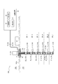
- the measurement system 100 includes a soil pressure gauge 10, a settlement gauge 20, an arithmetic unit 30, and an object 40 having a predetermined load.
- the earth pressure gauge 10 measures the earth pressure of the plurality of layers 201 with respect to the load of the object 40.
- the earth pressure gauge 10 outputs the measurement data of the earth pressure of the plurality of layers 201 with respect to the load of the object 40 to the arithmetic unit 30.
- the earth pressure of the plurality of layers 201 changes depending on the load of the object 40. For example, the earth pressure of the plurality of layers 201 when the first load is applied to the ground surface 200A and the earth pressure of the plurality of layers 201 when the second load different from the first load is applied to the ground surface 200A. And are different.
- the plurality of stratified soil pressure gauges 11 are inserted into each of the plurality of layers 201 from the side surface CA of the boring hole C formed by drilling the ground 200.
- the operator drills the ground 200 to a position deeper than the deepest layer (for example, layer 201_n) at which the ground reaction force coefficient is measured by the measurement system 100 to form a boring hole C.
- the operator inserts a plurality of stratified soil pressure gauges 11 connected to the signal line 12 at arbitrary intervals from the entrance of the boring hole C.
- the operator moves the plurality of stratified soil pressure gauges 11 inside the boring hole C so that the positions of the plurality of stratified soil pressure gauges 11 correspond to each of the plurality of layers 201.
- the layered soil pressure gauge 11 is inserted into each of the plurality of layers 201 from the side surface CA of the boring hole C by driving in the horizontal direction.
- the diameter of the boring hole C may be large enough to allow a plurality of stratified soil pressure gauges 11 to be inserted, but a smaller diameter is preferable.
- the stratified soil pressure gauge 11_k is inserted into the layer 201_k from the side surface CA of the boring hole C.
- the operator does not have to excavate a plurality of places of the ground according to each layer as in the conventional case. ..
- the excavation volume can be remarkably reduced as compared with the conventional one, so that the labor of the operator can be saved.
- the plurality of layered earth pressure gauges 11 measure the earth pressure of the plurality of layers 201 with respect to the load of the object 40.
- the plurality of layered earth pressure gauges 11 are connected to the arithmetic unit 30 via the signal line 12, and output the earth pressure of the plurality of layers 201 with respect to the measured load of the object 40 to the arithmetic unit 30.
- the layered earth pressure gauge 11_k measures the earth pressure of the layer 201_k with respect to the load of the object 40, and outputs the measurement data of the earth pressure of the layer 201_k to the arithmetic unit 30 via the signal line 12.
- the earth pressure is measured by the stratified earth pressure gauges 11 inserted into each of the plurality of layers 201 from one excavation point, so that the earth pressure gauge 10 can easily measure the earth pressure of the plurality of layers 201. it can.
- the plurality of stratified soil pressure gauges 11 are composed of, for example, plate type soil pressure gauges. By configuring the plurality of stratified soil pressure gauges 11 with the plate type soil pressure gauges, the operator can easily perform stratified soil from the side surface CA of the boring hole C to each of the plurality of layers 201 without disturbing the ground 200. A pressure gauge 11 can be inserted.
- the subsidence meter 20 measures the amount of subsidence of the plurality of layers 201 with respect to the load of the object 40.
- the subsidence meter 20 outputs measurement data of the amount of subsidence of the plurality of layers 201 with respect to the load of the object 40 to the arithmetic unit 30.
- the amount of subsidence of the plurality of layers 201 changes depending on the load of the object 40. For example, the amount of subsidence of the plurality of layers 201 when the first load is applied to the ground surface 200A and the amount of subsidence of the plurality of layers 201 when a second load different from the first load is applied to the ground surface 200A. And are different.
- the measuring unit 21 is provided on the ground surface 200A, and is fixed to the concrete base 52 of the ground 200 by, for example, an anchor bolt 51.
- the measuring unit 21 is connected to the plurality of anchors 22 via the signal line 25, and acquires the amount of movement of the plurality of anchors 22 in the vertical direction with respect to the load of the object 40.
- the measuring unit 21 measures the amount of subsidence of the plurality of layers 201 with respect to the load of the object 40 based on the amount of movement.
- the measuring unit 21 is connected to the arithmetic unit 30 via the signal line 25, and outputs the amount of subsidence of the plurality of layers 201 to the measured load of the object 40 to the arithmetic unit 30.
- the measuring unit 21 outputs the measurement data of the subsidence amount of the layer 201_k with respect to the load of the object 40 to the arithmetic unit 30 via the signal line 25.
- the anchor 22 is provided inside the boring hole C corresponding to each of the plurality of layers 201.
- the anchor 22_k is provided inside the boring hole C corresponding to the layer 201_k.
- the operator inserts a plurality of anchors 22 connected by rods 23 at arbitrary intervals from the entrance of the boring hole C. Then, the operator moves the plurality of anchors 22 inside the boring hole C so that the positions of the plurality of anchors 22 correspond to the positions of the plurality of layers 201. Then, the operator fixes the plurality of anchors 22 at appropriate positions inside the boring hole C. Then, the operator fills the inside of the boring hole C with the space filler 24 having a rigidity lower than the rigidity of the ground 200. As a result, it is possible to prevent the boring hole C from collapsing.
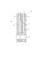
- the subsidence meter 20 may further include, for example, a pressure tube 26, a check valve 27, and the like. Further, the subsidence meter 20 may include a hydraulic anchor as the anchor 22. In this case, the operator flows water through the pressure tube 26 to apply water pressure to the hydraulic anchor to expand the ring diameter of the hydraulic anchor. As a result, the hydraulic anchor bites into the side surface CA of the boring hole C, so that the operator can fix the hydraulic anchor at an appropriate position inside the boring hole C. The high pressure state in the hydraulic anchor is maintained by the check valve 27.
- the plurality of anchors 22 have a mechanism for mechanically spreading, even if the settlement meter 20 does not have the above-described configuration, the operator can appropriately use the plurality of anchors 22 inside the boring hole C. It becomes possible to fix it in the position.
- the plurality of anchors 22 are located at the same positions as the plurality of stratified soil pressure gauges 11 in the horizontal direction within the same layer of the ground 200, or It is preferable that the soil pressure gauges 11 are provided closer to the ground surface 200A than the plurality of stratified soil pressure gauges 11.
- the anchor 22_k is preferably provided at the same position as the stratified soil pressure gauge 11_k in the horizontal direction in the layer 201_k of the ground 200, or at a position closer to the ground surface 20A than the stratified soil pressure gauge 11_k.
- the rod 23 internally accommodates a signal line 25 that connects a plurality of anchors 22 at arbitrary intervals, and protects the signal line 25.
- the load of the object 40 is applied to the ground surface 200A, the displacements generated in the plurality of anchors 22 are transmitted to the measuring unit 21 via the signal line 25 housed inside the rod 23.
- the space filler 24 fills the inside of the boring hole C.
- the space filler 24 is preferably selected by an operator in consideration of the rigidity of the ground 200, and is preferably formed of a material having a rigidity lower than the rigidity of the ground 200.
- the space filler 24 is preferably formed of a fluid such as a mixture of bentonite, cement, and water.
- the arithmetic unit 30 includes an arithmetic unit 31, a storage unit 32, and a display unit 33.
- the arithmetic unit 30 is provided on the ground 202 or the ground surface 200A.
- the arithmetic unit 30 measures the earth pressure measurement data of the plurality of layers 201 with respect to the load of the object 40 input from the earth pressure gauge 10, and the amount of subsidence of the plurality of layers 201 with respect to the load of the object 40 input from the subsidence meter 20. Based on the measurement data, the earth reaction force coefficients of the plurality of layers 201 are calculated.
- the arithmetic unit 31 may be configured by dedicated hardware, a general-purpose processor, or a processor specialized for a specific process.
- the calculation unit 31 is based on the measurement data of the earth pressure of the plurality of layers 201 with respect to the load of the object 40 and the measurement data of the subsidence amount of the plurality of layers 201 with respect to the load of the object 40, and the ground reaction force of the plurality of layers 201. Calculate the coefficient.
- the calculation unit 31 stores the ground reaction force coefficients of the plurality of layers 201 in the storage unit 32.
- the calculation unit 31 refers to, for example, measurement data of earth pressure of a plurality of layers 201 for each load stage of the object 40, measurement data of the amount of subsidence of the plurality of layers 201 for each load stage of the object 40, and a load of the object 40.
- a graph showing the relationship between earth pressure and the amount of subsidence, ground reaction force coefficients of a plurality of layers 201, and the like are displayed on the display unit 33.
- the calculation unit 31 determines the earth pressure of the predetermined layer 201_i measured by the earth pressure gauge 10 when the first load is applied to the ground surface 200A of the ground 200, and the predetermined earth pressure measured by the subsidence meter 20.
- the earth pressure coefficient of the predetermined layer 201_i is calculated.
- the calculation unit 31 calculates the ground reaction force coefficient of the predetermined layer 201_i based on the slope of the graph showing the relationship between the earth pressure and the subsidence amount as shown in FIG.
- soil reaction coefficient K i of a given layer 201_i is expressed as follows.
- K i is a ground reaction force coefficient of the layer 201_i [kN / m 3].
- p 1 is the earth pressure [kN / m 2] layers 201_i when the first load is applied to the ground surface 200A of the ground 200.
- p 2 is the earth pressure [kN / m 2] layers 201_i when the second load is applied to the ground surface 200A of the ground 200.
- s 1 is the subsidence amount [m] of the layer 201_i when the first load is applied to the ground surface 200A of the ground 200.
- s 2 is the subsidence amount [m] of the layer 201_i when the second load is applied to the ground surface 200A of the ground 200.
- the arithmetic unit 31, soil pressure p 1 and subsidence s 1 layer 201_i when the first load is applied to the ground surface 200A of the ground 200, and a second load is applied to the ground surface 200A of the ground 200 was based on the soil pressure p 2 and subsidence s 2 layers 201_I of time, it calculates the ground reaction force coefficient K i layer 201_I.
- the worker can change the load of the object 40 in stages.
- the finer the load of the object 40 is, the smoother the graph showing the relationship between earth pressure and the amount of subsidence.
- the calculation unit 31 can calculate the ground reaction force coefficient with high accuracy. Therefore, when the operator wants to improve the measurement accuracy of the ground reaction force coefficient in the measurement system 100, the operator may finely control the load of the object 40.
- the storage unit 32 includes one or more memories, and may include, for example, a semiconductor memory, a magnetic memory, an optical memory, and the like. Each memory included in the storage unit 32 may function as, for example, a main storage device, an auxiliary storage device, or a cache memory. Each memory does not necessarily have to be provided inside the arithmetic unit 30, and may be provided outside the arithmetic unit 30.
- the storage unit 32 stores arbitrary information used for the operation of the arithmetic unit 30.
- the storage unit 32 has, for example, the measurement data of the earth pressure of the plurality of layers 201 for each load stage of the object 40, the measurement data of the subsidence amount of the plurality of layers 201 for each load stage of the object 40, and the load of the object 40.
- a graph showing the relationship between earth pressure and the amount of subsidence, ground reaction force coefficients of a plurality of layers 201, and the like are stored.
- the storage unit 32 stores, for example, various programs, data, and the like.
- the display unit 33 is, for example, a speaker, a liquid crystal display, an organic EL (Electro-Luminescence) display, or the like.
- the display unit 33 may refer to, for example, measurement data of earth pressure of a plurality of layers 201 for each load stage of the object 40, measurement data of the amount of subsidence of the plurality of layers 201 for each load stage of the object 40, and a load of the object 40.
- a graph showing the relationship between earth pressure and the amount of subsidence, ground reaction force coefficients of a plurality of layers 201, and the like are displayed.
- the object 40 is, for example, a vehicle, and is provided on the ground surface 200A of the ground 200.
- the object 40 is changed stepwise by the operator. This makes it possible for the measurement system 100 to measure the earth pressure of the plurality of layers 201 and the amount of subsidence of the plurality of layers 201 in a wide range.
- step (formation step) S101 the operator drills the ground 200 to form the boring hole C.
- step (insertion step) S102 the operator inserts the stratified soil pressure gauge 11 into each of the plurality of layers 201 from the side surface CA of the boring hole C.
- step (installation step) S103 the operator provides an anchor 22 corresponding to each of the plurality of layers 201 inside the boring hole C.
- step (installation step) S104 the worker provides the object 40 on the ground surface 200A of the ground 200.
- step (first measurement step) S105 the earth pressure gauge 10 measures the earth pressure of the plurality of layers 201 with respect to the load of the object 40.
- the earth pressure gauge 10 outputs the measurement data of the earth pressure of the plurality of layers 201 with respect to the load of the object 40 to the arithmetic unit 30.
- step (second measurement step) S106 the subsidence meter 20 measures the amount of subsidence of the plurality of layers 201 with respect to the load of the object 40.
- the subsidence meter 20 outputs measurement data of the amount of subsidence of the plurality of layers 201 with respect to the load of the object 40 to the arithmetic unit 30.
- step (calculation step) S107 the arithmetic apparatus 30 refers to the measurement data of the earth pressure of the plurality of layers 201 with respect to the load of the object 40 input from the earth pressure gauge 10 and the load of the object 40 input from the sink gauge 20. Based on the measurement data of the amount of subsidence of the plurality of layers 201, the earth reaction force coefficients of the plurality of layers 201 are calculated.
- computing device 30 calculates the ground reaction force coefficient K i of a given layer 201_I.
- the measurement system 100 includes an earth pressure gauge that measures the earth pressure of a plurality of layers with respect to a load, a settlement meter that measures the amount of settlement of a plurality of layers with respect to a load, the earth pressure, and the earth pressure. It is provided with an arithmetic device for calculating the earth reaction force coefficient of a plurality of layers based on the amount of subsidence.
- the earth pressure of a plurality of layers with respect to the load is measured, the amount of subsidence of the plurality of layers with respect to the load is measured, and the ground reaction of the plurality of layers is measured based on the earth pressure and the amount of subsidence. Calculate the force coefficient.
- the stratified soil pressure gauge 11 is inserted into each of the plurality of layers 201 from the side surface CA of the boring hole C, the operator does not excavate a plurality of places of the ground according to each layer as in the conventional case. I'm done. As a result, the excavation volume can be remarkably reduced as compared with the conventional one, so that the labor of the operator can be saved.
- the earth pressure is measured by the stratified earth pressure gauges 11 inserted into each of the plurality of layers 201 from one excavation point, so that the earth pressure gauge 10 can easily measure the earth pressure of the plurality of layers 201. be able to.
- the subsidence total 20 can easily measure the subsidence amount of the plurality of layers 201.
- the inside of the boring hole C is filled with the space filling material 24, and the space filling material 24 has a rigidity lower than the rigidity of the ground 200, so that the displacement generated in the ground 200 and the plurality of anchors 22 around the boring hole C is generated. Since it is difficult for an error to occur between the two, the measurement accuracy can be improved.
- a data logger device having a graph display function, a general-purpose computer, a dedicated computer, a workstation, a PC, an electronic notepad, or the like can be applied.
- Soil pressure gauge 11 Soil pressure gauge by layer 12 Signal line 20 Sink meter 21 Measuring unit 22 Anchor 23 Rod 24 Space filling material 25 Signal line 26 Pressurizing tube 27
- Check valve 30 Calculation device 31
- Calculation unit 32 Storage unit 33 Display unit 40 Object 100 Measurement system 200 Ground 200A Ground surface 201 Layer 202 Ground
Landscapes
- Life Sciences & Earth Sciences (AREA)
- Engineering & Computer Science (AREA)
- Chemical & Material Sciences (AREA)
- Analytical Chemistry (AREA)
- Structural Engineering (AREA)
- Physics & Mathematics (AREA)
- Mining & Mineral Resources (AREA)
- Paleontology (AREA)
- Civil Engineering (AREA)
- General Engineering & Computer Science (AREA)
- Soil Sciences (AREA)
- General Life Sciences & Earth Sciences (AREA)
- General Physics & Mathematics (AREA)
- Health & Medical Sciences (AREA)
- Biochemistry (AREA)
- General Health & Medical Sciences (AREA)
- Immunology (AREA)
- Pathology (AREA)
- Investigation Of Foundation Soil And Reinforcement Of Foundation Soil By Compacting Or Drainage (AREA)
- Force Measurement Appropriate To Specific Purposes (AREA)
Abstract
地盤(200)における深さが異なる複数の層の地盤反力係数を測定する測定システム(100)であって、地盤(200)の地表面(200A)に設けられた物体(40)と、物体(40)の荷重に対する複数の層(201)の土圧を計測する土圧計(10)と、物体(40)の荷重に対する複数の層(201)の沈下量を計測する沈下計(20)と、該土圧および該沈下量に基づいて、複数の層の地盤反力係数を演算する演算装置(30)と、を備える。
Description
本発明は、測定システムおよび測定方法に関する。
構造物基礎地盤における変形、強さなどの支持力特性を表す数値に地盤反力係数があり、構造物の設計に利用される。例えば、非特許文献1および非特許文献2には、地盤を開削してジャッキを設置し、剛な載荷板を介して地表面に荷重を与え、反力の作用に伴う載荷圧力および載荷板の沈下量を計測する平板載荷試験方法が開示されている。地盤反力係数は、載荷圧力と載荷板の沈下量との関係を示すグラフの傾きに基づいて演算される。
「平板載荷試験方法」、地盤工学会、[online]、[2019年12月23日検索]、インターネット<URL:https://jiban.or.jp/file/file/jgs1521_201109.pdf>
「平板載荷試験」、株式会社CSS技術開発、[online]、[2019年12月23日検索]、インターネット<URL:https://www.css24.jp/download/img/pdf/6-6heiban.pdf>
しかしながら、従来の平板載荷試験方法では、地盤の開削および反力を支えるジャッキが必要であり、地盤を深く開削する程、測定装置が大きくなり、コストがかかるという問題があった。また、地盤は深さによって土性が異なるため、土性が異なる複数の層の地盤反力係数を測定するためには、作業者が各層に合わせて地盤の複数個所を掘削する必要があり、コストおよび手間がかかるという問題もあった。
かかる事情に鑑みてなされた本発明の目的は、コストを低減しつつ、地盤における深さが異なる複数の層の地盤反力係数を、簡易に測定可能な測定システムおよび測定方法を提供することにある。
一実施形態に係る測定システムは、地盤における深さが異なる複数の層の地盤反力係数を測定する測定システムであって、前記地盤の地表面に設けられた物体と、前記物体の荷重に対する前記複数の層の土圧を計測する土圧計と、前記物体の荷重に対する前記複数の層の沈下量を計測する沈下計と、前記土圧および前記沈下量に基づいて、前記複数の層の地盤反力係数を演算する演算装置と、を備えることを特徴とする。
一実施形態に係る測定方法は、地盤における深さが異なる複数の層の地盤反力係数を測定する測定方法であって、前記地盤の地表面に物体を設ける設置ステップと、前記物体の荷重に対する前記複数の層の土圧を計測する第1計測ステップと、前記物体の荷重に対する前記複数の層の沈下量を計測する第2計測ステップと、前記土圧および前記沈下量に基づいて、前記複数の層の地盤反力係数を演算する演算ステップと、を含むことを特徴とする。
本発明によれば、コストを低減しつつ、地盤における深さが異なる複数の層の地盤反力係数を、簡易に測定可能な測定システムおよび測定方法を提供することが可能となる。
以下、本発明の一実施形態について、図面を参照して詳細に説明する。
<測定システム>
図1乃至図3を参照して、本発明の一実施形態に係る測定システム100について説明する。
図1乃至図3を参照して、本発明の一実施形態に係る測定システム100について説明する。
測定システム100は、地盤200における深さ(土性)が異なる複数の層201_k(k=1~n)の地盤反力係数を測定する測定システムである。測定システム100は、土圧計10と、沈下計20と、演算装置30と、所定の荷重の物体40と、を備える。
土圧計10は、複数の層別土圧計11_k(k=1~n)と、信号線12と、を備える。土圧計10は、物体40の荷重に対する複数の層201の土圧を計測する。土圧計10は、物体40の荷重に対する複数の層201の土圧の計測データを、演算装置30へ出力する。
複数の層201の土圧は、物体40の荷重によって変化する。例えば、地表面200Aに第1荷重がかけられたときの複数の層201の土圧と、地表面200Aに第1荷重とは異なる第2荷重がかけられたときの複数の層201の土圧と、は相違する。
複数の層別土圧計11は、地盤200を削孔して形成されたボーリング孔Cの側面CAから複数の層201のそれぞれに挿入される。作業者は、測定システム100により地盤反力係数が測定される最深層(例えば、層201_n)よりも深い位置まで、地盤200を削孔してボーリング孔Cを形成する。そして、作業者は、ボーリング孔Cの入り口から、信号線12と任意の間隔で接続された複数の層別土圧計11を挿入する。そして、作業者は、複数の層別土圧計11の位置が、複数の層201のそれぞれと対応する位置となるように、ボーリング孔Cの内部において、複数の層別土圧計11を移動させる。そして、作業者は、ボーリング孔Cの内部において、複数の層別土圧計11を適切な位置で停止させて、複数の層別土圧計11の計測部とは逆側の端部を、ハンマーなどで水平方向に打ち込むことにより、ボーリング孔Cの側面CAから複数の層201のそれぞれに層別土圧計11を挿入する。ボーリング孔Cの径は、複数の層別土圧計11を挿入可能な程度の大きさであればよいが、小さい方が好ましい。
例えば、層別土圧計11_kは、ボーリング孔Cの側面CAから層201_kに挿入される。層別土圧計11が、ボーリング孔Cの側面CAから複数の層201のそれぞれに挿入されることで、従来のように、作業者は、各層に合わせて地盤の複数個所を掘削せずに済む。これにより、掘削体積を従来と比較して格段に小さくすることができるため、作業者の手間を省くことができる。
複数の層別土圧計11は、物体40の荷重に対する複数の層201の土圧を計測する。複数の層別土圧計11は、信号線12を介して、演算装置30に接続され、計測した物体40の荷重に対する複数の層201の土圧を、演算装置30へ出力する。例えば、層別土圧計11_kは、物体40の荷重に対する層201_kの土圧を計測し、層201_kの土圧の計測データを、信号線12を介して、演算装置30へ出力する。1つの掘削箇所から複数の層201のそれぞれに挿入された層別土圧計11により土圧の計測が行われることで、土圧計10は、複数の層201の土圧を簡易に計測することができる。
複数の層別土圧計11は、例えば、プレート式土圧計で構成される。複数の層別土圧計11がプレート式土圧計で構成されることで、作業者は、地盤200を乱すことなく、簡易に、ボーリング孔Cの側面CAから複数の層201のそれぞれに層別土圧計11を挿入することができる。
プレート式土圧計の詳細については、例えば、下記の文献を参照することができる。
「GTI-E201-Sプレート式土圧計」、株式会社共和電業、インターネット<URL: https://www.kyowa-ei.com/jpn/file/download/support/download/catalog/gti-e201-s_catalog_j2019_01_jpn.pdf>,
「GTI-E201-Sプレート式土圧計」、株式会社共和電業、インターネット<URL: https://www.kyowa-ei.com/jpn/file/download/support/download/catalog/gti-e201-s_catalog_j2019_01_jpn.pdf>,
沈下計20は、計測部21と、複数のアンカー22_k(k=1~n)と、ロッド23と、空間充填材24と、信号線25と、を備える。沈下計20は、物体40の荷重に対する複数の層201の沈下量を計測する。沈下計20は、物体40の荷重に対する複数の層201の沈下量の計測データを、演算装置30へ出力する。
複数の層201の沈下量は、物体40の荷重によって変化する。例えば、地表面200Aに第1荷重がかけられたときの複数の層201の沈下量と、地表面200Aに第1荷重とは異なる第2荷重がかけられたときの複数の層201の沈下量と、は相違する。
計測部21は、地表面200Aに設けられ、例えば、アンカボルト51で、地盤200のコンクリートベース52に固定されている。計測部21は、信号線25を介して、複数のアンカー22と接続され、物体40の荷重に対する複数のアンカー22の鉛直方向における移動量を取得する。計測部21は、当該移動量に基づいて、物体40の荷重に対する複数の層201の沈下量を計測する。
また、計測部21は、信号線25を介して、演算装置30に接続され、計測した物体40の荷重に対する複数の層201の沈下量を、演算装置30へ出力する。例えば、計測部21は、物体40の荷重に対する層201_kの沈下量の計測データを、信号線25を介して、演算装置30へ出力する。
アンカー22は、ボーリング孔Cの内部に複数の層201のそれぞれと対応して設けられる。例えば、アンカー22_kは、ボーリング孔Cの内部に層201_kと対応して設けられる。ボーリング孔Cの内部において、複数の層201のそれぞれと対応する位置にアンカー22が設けられることで、沈下計20は、複数の層201の沈下量を簡易に計測することができる。
作業者は、ボーリング孔Cの入り口から、ロッド23により任意の間隔で連結された複数のアンカー22を挿入する。そして、作業者は、複数のアンカー22の位置が、複数の層201のそれぞれと対応する位置となるように、ボーリング孔Cの内部において、複数のアンカー22を移動させる。そして、作業者は、ボーリング孔Cの内部において、複数のアンカー22を適切な位置で固定する。そして、作業者は、ボーリング孔Cの内部を、地盤200の剛性より低い剛性を有する空間充填材24により充填する。これにより、ボーリング孔Cが崩れることを抑制することができる。
ここで、図2を参照して、作業者がボーリング孔Cの内部において複数のアンカー22を固定する方法の一例について説明する。
沈下計20は、例えば、加圧チューブ26、逆止弁27などをさらに備えていてもよい。また、沈下計20は、アンカー22として水圧式アンカーを備えていてもよい。この場合、作業者は、加圧チューブ26に水を流して、水圧式アンカーに水圧を加え、水圧式アンカーの環径を膨張させる。これにより、水圧式アンカーがボーリング孔Cの側面CAに食い込むため、作業者は、ボーリング孔Cの内部において、水圧式アンカーを、適切な位置に固定することが可能になる。水圧式アンカー内の高圧状態は、逆止弁27により維持される。なお、複数のアンカー22がメカニカルに広がる機構を有する場合には、沈下計20が上述した構成を備えていなくても、作業者は、ボーリング孔Cの内部において、複数のアンカー22を、適切な位置に固定することが可能になる。
複数のアンカー22は、物体40の荷重に対する応力伝播に伴う地盤200の土粒子の移動を鑑みると、地盤200の同じ層内の水平方向において、複数の層別土圧計11と同じ位置、あるいは、複数の層別土圧計11より地表面200Aに近い位置に設けられることが好ましい。例えば、アンカー22_kは、地盤200の層201_k内の水平方向において、層別土圧計11_kと同じ位置、あるいは、層別土圧計11_kより地表面20Aに近い位置に設けられることが好ましい。
ロッド23は、複数のアンカー22を任意の間隔で連結する信号線25を、内部に収容し、信号線25を保護する。地表面200Aに物体40の荷重がかけられることにより、複数のアンカー22に生じる変位は、ロッド23の内部に収容される信号線25を介して、計測部21へ伝達される。
空間充填材24は、ボーリング孔Cの内部を充填する。空間充填材24は、地盤200の剛性を考慮して、作業者により適宜選定されることが好ましく、地盤200の剛性より低い剛性を有する材料で形成されることが好ましい。空間充填材24が剛性の強い固体材料である場合、ボーリング孔Cの周辺の地盤200と複数のアンカー22に生じる変位との間に誤差が生じてしまい、計測精度が悪くなる。このため、空間充填材24は、例えば、ベントナイト、セメント、水の混合体などの流動体で形成されることが好ましい。
演算装置30は、演算部31と、記憶部32と、表示部33と、を備える。演算装置30は、地上202あるいは地表面200Aに設けられる。演算装置30は、土圧計10から入力された物体40の荷重に対する複数の層201の土圧の計測データ、および、沈下計20から入力された物体40の荷重に対する複数の層201の沈下量の計測データに基づいて、複数の層201の地盤反力係数を演算する。
演算部31は、専用のハードウェアによって構成されてもよいし、汎用のプロセッサ又は特定の処理に特化したプロセッサによって構成されてもよい。
演算部31は、物体40の荷重に対する複数の層201の土圧の計測データ、および、物体40の荷重に対する複数の層201の沈下量の計測データに基づいて、複数の層201の地盤反力係数を演算する。演算部31は、複数の層201の地盤反力係数を、記憶部32に記憶させる。演算部31は、例えば、物体40の荷重の段階ごとの複数の層201の土圧の計測データ、物体40の荷重の段階ごとの複数の層201の沈下量の計測データ、物体40の荷重に対する土圧と沈下量との関係を示すグラフ、複数の層201の地盤反力係数などを、表示部33に表示させる。
例えば、演算部31は、地盤200の地表面200Aに第1荷重がかけられたときの、土圧計10により計測された所定の層201_iの土圧、および、沈下計20により計測された所定の層201_iの沈下量、並びに、地盤200の地表面200Aに第1荷重とは異なる第2荷重がかけられたときの、土圧計10により計測された所定の層201_iの土圧、および、沈下計20により計測された所定の層201_iの沈下量に基づいて、所定の層201_iの地盤反力係数を演算する。
演算部31は、図3に示すような土圧と沈下量との関係を示すグラフの傾きに基づいて、所定の層201_iの地盤反力係数を演算する。例えば、所定の層201_iの地盤反力係数Kiは、次式のように表せる。

Kiは、層201_iの地盤反力係数[kN/m3]である。p1は、地盤200の地表面200Aに第1荷重がかけられたときの層201_iの土圧[kN/m2]である。p2は、地盤200の地表面200Aに第2荷重がかけられたときの層201_iの土圧[kN/m2]である。s1は、地盤200の地表面200Aに第1荷重がかけられたときの層201_iの沈下量[m]である。s2は、地盤200の地表面200Aに第2荷重がかけられたときの層201_iの沈下量[m]である。
すなわち、演算部31は、地盤200の地表面200Aに第1荷重がかけられたときの層201_iの土圧p1および沈下量s1、並びに、地盤200の地表面200Aに第2荷重がかけられたときの層201_iの土圧p2および沈下量s2に基づいて、層201_iの地盤反力係数Kiを演算する。
作業者は、物体40の荷重を段階的に変更することが可能である。作業者が物体40の荷重を細かく刻む程、土圧と沈下量との関係を示すグラフは、より滑らかになる。この結果、演算部31は、地盤反力係数を高精度に演算することが可能になる。したがって、作業者は、測定システム100における地盤反力係数の計測精度を高めたい場合、物体40の荷重を細かく制御すればよい。
記憶部32は、1つ以上のメモリを含み、例えば、半導体メモリ、磁気メモリ、光メモリなどを含んでよい。記憶部32に含まれる各メモリは、例えば、主記憶装置、補助記憶装置、又はキャッシュメモリとして機能してよい。各メモリは、必ずしも演算装置30がその内部に備える必要はなく、演算装置30の外部に備える構成としてもよい。記憶部32は、演算装置30の動作に用いられる任意の情報を記憶する。記憶部32は、例えば、物体40の荷重の段階ごとの複数の層201の土圧の計測データ、物体40の荷重の段階ごとの複数の層201の沈下量の計測データ、物体40の荷重に対する土圧と沈下量との関係を示すグラフ、複数の層201の地盤反力係数などを記憶する。この他にも、記憶部32は、例えば、各種のプログラム、データなどを記憶する。
表示部33は、例えば、スピーカー、液晶ディスプレイ、有機EL(Electro-Luminescence)ディスプレイなどである。表示部33は、例えば、物体40の荷重の段階ごとの複数の層201の土圧の計測データ、物体40の荷重の段階ごとの複数の層201の沈下量の計測データ、物体40の荷重に対する土圧と沈下量との関係を示すグラフ、複数の層201の地盤反力係数などを表示する。
物体40は、例えば、車両であり、地盤200の地表面200Aに設けられる。物体40は、作業者により段階的に変更される。これにより、測定システム100は、広いレンジで、複数の層201の土圧および複数の層201の沈下量を計測することが可能となる。
<測定方法>
次に、図4を参照して、本発明の一実施形態に係る測定方法について説明する。
次に、図4を参照して、本発明の一実施形態に係る測定方法について説明する。
ステップ(形成ステップ)S101において、作業者は、地盤200を削孔してボーリング孔Cを形成する。
ステップ(挿入ステップ)S102において、作業者は、ボーリング孔Cの側面CAから複数の層201のそれぞれに層別土圧計11を挿入する。
ステップ(設置ステップ)S103において、作業者は、ボーリング孔Cの内部に複数の層201のそれぞれと対応するアンカー22を設ける。
ステップ(設置ステップ)S104において、作業者は、地盤200の地表面200Aに物体40を設ける。
ステップ(第1計測ステップ)S105において、土圧計10は、物体40の荷重に対する複数の層201の土圧を計測する。土圧計10は、物体40の荷重に対する複数の層201の土圧の計測データを、演算装置30へ出力する。
ステップ(第2計測ステップ)S106において、沈下計20は、物体40の荷重に対する複数の層201の沈下量を計測する。沈下計20は、物体40の荷重に対する複数の層201の沈下量の計測データを、演算装置30へ出力する。
ステップ(演算ステップ)S107において、演算装置30は、土圧計10から入力された物体40の荷重に対する複数の層201の土圧の計測データ、および、沈下計20から入力された物体40の荷重に対する複数の層201の沈下量の計測データに基づいて、複数の層201の地盤反力係数を演算する。例えば、演算装置30は、地盤200の地表面200Aに第1荷重がかけられたときの所定の層201_iの土圧p1および沈下量s1、並びに、地盤200の地表面200Aに第2荷重がかけられたときの所定の層201_iの土圧p2および沈下量s2に基づいて、所定の層201_iの地盤反力係数Kiを演算する。
上述したように、本実施形態に係る測定システム100は、荷重に対する複数の層の土圧を計測する土圧計と、荷重に対する複数の層の沈下量を計測する沈下計と、該土圧および該沈下量に基づいて、複数の層の地盤反力係数を演算する演算装置と、を備える。
本実施形態に係る測定方法は、荷重に対する複数の層の土圧を計測し、荷重に対する複数の層の沈下量を計測し、該土圧および該沈下量に基づいて、複数の層の地盤反力係数を演算する。
これにより、地盤の深い位置に存在する層の地盤反力係数を、大規模な測定装置を必要とすることなく測定することができる。また、地盤を1箇所掘削するのみで、深さが異なる複数の層の地盤反力係数を簡易に測定できるため、作業者の手間を省き、コストを抑えることができる。すなわち、コストを低減しつつ、地盤における深さが異なる複数の層の地盤反力係数を、簡易に測定することが可能な測定システム100および測定方法を実現できる。
また、層別土圧計11が、ボーリング孔Cの側面CAから複数の層201のそれぞれに挿入されることで、従来のように、作業者は、各層に合わせて地盤の複数個所を掘削せずに済む。これにより、掘削体積を従来と比較して格段に小さくすることができるため、作業者の手間を省くことができる。
また、1つの掘削箇所から複数の層201のそれぞれに挿入された層別土圧計11により土圧の計測が行われることで、土圧計10は、複数の層201の土圧を簡易に計測することができる。
また、ボーリング孔Cの内部において、複数の層201のそれぞれと対応する位置にアンカー22が設けられることで、沈下計20は、複数の層201の沈下量を簡易に計測することができる。
また、ボーリング孔Cの内部が空間充填材24で充填され、空間充填材24が地盤200の剛性より低い剛性を有することで、ボーリング孔Cの周辺の地盤200と複数のアンカー22に生じる変位との間に誤差が生じ難くなるため、計測精度を高めることができる。
上述の実施形態は代表的な例として説明したが、本発明の趣旨および範囲内で、多くの変更および置換ができることは当業者に明らかである。したがって、本発明は、上述の実施形態によって制限するものと解するべきではなく、請求の範囲から逸脱することなく、種々の変形や変更が可能である。例えば、実施形態のフローチャートに記載の各工程の順序は、上記に限定されず適宜変更可能である。また、複数の工程を1つに組み合わせたり、あるいは1つの工程を分割したりすることが可能である。
<変形例>
本実施形態に係る演算装置として、例えば、グラフ表示機能を有するデータロガー装置、汎用コンピュータ、専用コンピュータ、ワークステーション、PC、電子ノートパッドなどを適用できる。
本実施形態に係る演算装置として、例えば、グラフ表示機能を有するデータロガー装置、汎用コンピュータ、専用コンピュータ、ワークステーション、PC、電子ノートパッドなどを適用できる。
<その他の変形例>
本発明は上記の実施形態および変形例に限定されるものではない。例えば、上述の各種の処理は、記載にしたがって時系列に実行されるのみならず、処理を実行する装置の処理能力あるいは必要に応じて並列的にあるいは個別に実行されてもよい。その他、本発明の趣旨を逸脱しない範囲で適宜変更が可能である。
本発明は上記の実施形態および変形例に限定されるものではない。例えば、上述の各種の処理は、記載にしたがって時系列に実行されるのみならず、処理を実行する装置の処理能力あるいは必要に応じて並列的にあるいは個別に実行されてもよい。その他、本発明の趣旨を逸脱しない範囲で適宜変更が可能である。
10 土圧計
11 層別土圧計
12 信号線
20 沈下計
21 計測部
22 アンカー
23 ロッド
24 空間充填材
25 信号線
26 加圧チューブ
27 逆止弁
30 演算装置
31 演算部
32 記憶部
33 表示部
40 物体
100 測定システム
200 地盤
200A 地表面
201 層
202 地上
11 層別土圧計
12 信号線
20 沈下計
21 計測部
22 アンカー
23 ロッド
24 空間充填材
25 信号線
26 加圧チューブ
27 逆止弁
30 演算装置
31 演算部
32 記憶部
33 表示部
40 物体
100 測定システム
200 地盤
200A 地表面
201 層
202 地上
Claims (7)
- 地盤における深さが異なる複数の層の地盤反力係数を測定する測定システムであって、
前記地盤の地表面に設けられた物体と、
前記物体の荷重に対する前記複数の層の土圧を計測する土圧計と、
前記物体の荷重に対する前記複数の層の沈下量を計測する沈下計と、
前記土圧および前記沈下量に基づいて、前記複数の層の地盤反力係数を演算する演算装置と、
を備える測定システム。 - 前記土圧計は、前記地盤を削孔して形成されたボーリング孔の側面から前記複数の層のそれぞれに挿入された層別土圧計により、前記土圧を計測し、
前記沈下計は、前記ボーリング孔の内部に前記複数の層のそれぞれと対応して設けられたアンカーの鉛直方向における移動量に基づいて、前記沈下量を計測する、
請求項1に記載の測定システム。 - 前記ボーリング孔の内部に充填される空間充填材をさらに備える、
請求項2に記載の測定システム。 - 前記空間充填材は、前記地盤の剛性より低い剛性を有する、
請求項3に記載の測定システム。 - 前記演算装置は、前記地表面に第1荷重がかけられたときの所定の層の土圧および沈下量、並びに、前記地表面に前記第1荷重とは異なる第2荷重がかけられたときの前記所定の層の土圧および沈下量に基づいて、前記所定の層の地盤反力係数を演算する、
請求項1から4のいずれか一項に記載の測定システム。 - 地盤における深さが異なる複数の層の地盤反力係数を測定する測定方法であって、
前記地盤の地表面に物体を設ける設置ステップと、
前記物体の荷重に対する前記複数の層の土圧を計測する第1計測ステップと、
前記物体の荷重に対する前記複数の層の沈下量を計測する第2計測ステップと、
前記土圧および前記沈下量に基づいて、前記複数の層の地盤反力係数を演算する演算ステップと、
を含む測定方法。 - 前記地盤を削孔してボーリング孔を形成する形成ステップと、
前記ボーリング孔の側面から前記複数の層のそれぞれに層別土圧計を挿入する挿入ステップと、
前記ボーリング孔の内部に前記複数の層のそれぞれと対応するアンカーを設ける設置ステップと、をさらに含み、
前記第1計測ステップは、
前記層別土圧計により、前記土圧を計測し、
前記第2計測ステップは、
前記アンカーの鉛直方向における移動量に基づいて、前記沈下量を計測する、
請求項6に記載の測定方法。
Priority Applications (3)
| Application Number | Priority Date | Filing Date | Title |
|---|---|---|---|
| PCT/JP2020/000351 WO2021140596A1 (ja) | 2020-01-08 | 2020-01-08 | 測定システムおよび測定方法 |
| US17/791,146 US20230023924A1 (en) | 2020-01-08 | 2020-01-08 | Measuring system and measuring method |
| JP2021569653A JP7299534B2 (ja) | 2020-01-08 | 2020-01-08 | 測定システムおよび測定方法 |
Applications Claiming Priority (1)
| Application Number | Priority Date | Filing Date | Title |
|---|---|---|---|
| PCT/JP2020/000351 WO2021140596A1 (ja) | 2020-01-08 | 2020-01-08 | 測定システムおよび測定方法 |
Publications (1)
| Publication Number | Publication Date |
|---|---|
| WO2021140596A1 true WO2021140596A1 (ja) | 2021-07-15 |
Family
ID=76788168
Family Applications (1)
| Application Number | Title | Priority Date | Filing Date |
|---|---|---|---|
| PCT/JP2020/000351 Ceased WO2021140596A1 (ja) | 2020-01-08 | 2020-01-08 | 測定システムおよび測定方法 |
Country Status (3)
| Country | Link |
|---|---|
| US (1) | US20230023924A1 (ja) |
| JP (1) | JP7299534B2 (ja) |
| WO (1) | WO2021140596A1 (ja) |
Families Citing this family (1)
| Publication number | Priority date | Publication date | Assignee | Title |
|---|---|---|---|---|
| CN118032497B (zh) * | 2024-02-21 | 2024-08-09 | 北京科技大学 | 一种交通荷载下足尺钢筋混凝土管道的服役性能研究系统 |
Citations (7)
| Publication number | Priority date | Publication date | Assignee | Title |
|---|---|---|---|---|
| JP2001193069A (ja) * | 2000-01-17 | 2001-07-17 | Ohbayashi Corp | 土留め掘削時の計測管理方法、土留め掘削時の計測管理システム、および、土留め掘削時の計測管理システムを実現するためのコンピュータプログラムを記録した記録媒体 |
| JP2002296159A (ja) * | 2001-03-30 | 2002-10-09 | Matsumura Gumi Corp | 平板載荷試験装置及び記録媒体 |
| JP2004309181A (ja) * | 2003-04-02 | 2004-11-04 | Taisei Corp | 地盤沈下計測装置及び方法 |
| JP2004333396A (ja) * | 2003-03-12 | 2004-11-25 | Shimizu Corp | 地盤測定装置、地盤測定方法、地盤建設方法およびプログラム |
| JP2004332400A (ja) * | 2003-05-08 | 2004-11-25 | Shimizu Corp | 地盤係数測定方法、地盤係数導出装置、地盤建設方法およびプログラム |
| JP2015081469A (ja) * | 2013-10-23 | 2015-04-27 | 株式会社大林組 | 前方地山の探査方法 |
| JP2015200096A (ja) * | 2014-04-08 | 2015-11-12 | 大成建設株式会社 | 層別沈下計の設置方法および層別沈下計測システム |
Family Cites Families (4)
| Publication number | Priority date | Publication date | Assignee | Title |
|---|---|---|---|---|
| EP1707683A1 (en) * | 2003-12-26 | 2006-10-04 | Masuda Giken Co., Ltd. | Testing method and apparatus ground liquefaction and dynamic characteristics in original position utilizing boring hole |
| EP3247837A2 (en) * | 2015-01-21 | 2017-11-29 | Roger Arnold Stromsoe | An impact compactor, compaction system and a method of obtaining soil strength |
| CN107607405A (zh) * | 2017-09-06 | 2018-01-19 | 东南大学 | 一种用于深部土体荷载变形测试的标准贯入器及操作方法 |
| CN110080746A (zh) * | 2019-05-24 | 2019-08-02 | 北京爱地地质勘察基础工程公司 | 一种原位钻孔压缩试验设备及其使用方法 |
-
2020
- 2020-01-08 WO PCT/JP2020/000351 patent/WO2021140596A1/ja not_active Ceased
- 2020-01-08 US US17/791,146 patent/US20230023924A1/en not_active Abandoned
- 2020-01-08 JP JP2021569653A patent/JP7299534B2/ja active Active
Patent Citations (7)
| Publication number | Priority date | Publication date | Assignee | Title |
|---|---|---|---|---|
| JP2001193069A (ja) * | 2000-01-17 | 2001-07-17 | Ohbayashi Corp | 土留め掘削時の計測管理方法、土留め掘削時の計測管理システム、および、土留め掘削時の計測管理システムを実現するためのコンピュータプログラムを記録した記録媒体 |
| JP2002296159A (ja) * | 2001-03-30 | 2002-10-09 | Matsumura Gumi Corp | 平板載荷試験装置及び記録媒体 |
| JP2004333396A (ja) * | 2003-03-12 | 2004-11-25 | Shimizu Corp | 地盤測定装置、地盤測定方法、地盤建設方法およびプログラム |
| JP2004309181A (ja) * | 2003-04-02 | 2004-11-04 | Taisei Corp | 地盤沈下計測装置及び方法 |
| JP2004332400A (ja) * | 2003-05-08 | 2004-11-25 | Shimizu Corp | 地盤係数測定方法、地盤係数導出装置、地盤建設方法およびプログラム |
| JP2015081469A (ja) * | 2013-10-23 | 2015-04-27 | 株式会社大林組 | 前方地山の探査方法 |
| JP2015200096A (ja) * | 2014-04-08 | 2015-11-12 | 大成建設株式会社 | 層別沈下計の設置方法および層別沈下計測システム |
Also Published As
| Publication number | Publication date |
|---|---|
| US20230023924A1 (en) | 2023-01-26 |
| JP7299534B2 (ja) | 2023-06-28 |
| JPWO2021140596A1 (ja) | 2021-07-15 |
Similar Documents
| Publication | Publication Date | Title |
|---|---|---|
| Niazi et al. | Cone penetration test based direct methods for evaluating static axial capacity of single piles | |
| Xu et al. | Pipe pile installation effects in soft clay | |
| Zwanenburg et al. | Laboratory, in situ and full-scale load tests to assess flood embankment stability on peat | |
| Fan et al. | Lateral response of piles subjected to a combination of spudcan penetration and pile head loads | |
| Nejjar et al. | Experimental study of the performance of a 32 m deep excavation in the suburbs of Paris | |
| Kong et al. | Installation effects of the post-grouted micropile in marine soft clay | |
| Prendergast et al. | Examination of the reduction in natural frequency of laterally loaded piles due to strain-dependence of soil shear modulus | |
| Hu et al. | Failure investigation at a collapsed deep open cut slope excavation in soft clay | |
| Farrokhzad et al. | Seismic behaviour of excavations reinforced with soil–nailing method | |
| Nazir et al. | Appraisal of reliable skin friction variation in a bored pile | |
| Verumandy et al. | Static load testing of instrumented screw piles in soft soil deposits | |
| Alielahi et al. | Comparison between empirical and experimental ultimate bearing capacity of bored piles—a case study | |
| Barbosa et al. | Offshore pile load tests in chalk | |
| Wiesenthal et al. | Concept on plug development in jacked open-ended piles in clay considering total stresses | |
| Chalajour et al. | Prediction of drag force on piles subjected to negative skin friction induced by bridge embankment construction based on measured field data | |
| JP7299534B2 (ja) | 測定システムおよび測定方法 | |
| Razeghi et al. | Effect of geometrical properties on mechanical behavior of cantilever pile walls (CPW): centrifuge tests | |
| JP3690467B2 (ja) | 地盤定数の推定方法 | |
| Nguyen et al. | Bidirectional tests on two shaft-grouted barrette piles in Mekong Delta, Vietnam | |
| Nip et al. | Back-analysis of laterally loaded bored piles | |
| Al Shafian et al. | A Finite Element Approach to Investigate the Deformation Behaviour in Deep Excavation for TBM Launching Shaft | |
| Fellenius et al. | Combination of O-cell test and conventional head-down test | |
| Choy et al. | Stability of a loaded pile adjacent to a slurry-supported trench | |
| Zhu | Mindlin solution on ground deformation caused by the trench excavation during installation of concrete diaphragm wall panels | |
| Kim | Observed performance and inverse analysis of a sheet pile-supported excavation in Chicago clays |
Legal Events
| Date | Code | Title | Description |
|---|---|---|---|
| 121 | Ep: the epo has been informed by wipo that ep was designated in this application |
Ref document number: 20913013 Country of ref document: EP Kind code of ref document: A1 |
|
| ENP | Entry into the national phase |
Ref document number: 2021569653 Country of ref document: JP Kind code of ref document: A |
|
| NENP | Non-entry into the national phase |
Ref country code: DE |
|
| 122 | Ep: pct application non-entry in european phase |
Ref document number: 20913013 Country of ref document: EP Kind code of ref document: A1 |