WO2021132409A1 - Spunbond nonwoven fabric for filters, filter medium for powder-coated filters, and powder-coated filter - Google Patents
Spunbond nonwoven fabric for filters, filter medium for powder-coated filters, and powder-coated filter Download PDFInfo
- Publication number
- WO2021132409A1 WO2021132409A1 PCT/JP2020/048312 JP2020048312W WO2021132409A1 WO 2021132409 A1 WO2021132409 A1 WO 2021132409A1 JP 2020048312 W JP2020048312 W JP 2020048312W WO 2021132409 A1 WO2021132409 A1 WO 2021132409A1
- Authority
- WO
- WIPO (PCT)
- Prior art keywords
- filter
- woven fabric
- fused
- spunbonded
- spunbonded non
- Prior art date
Links
Images


Classifications
-
- B—PERFORMING OPERATIONS; TRANSPORTING
- B01—PHYSICAL OR CHEMICAL PROCESSES OR APPARATUS IN GENERAL
- B01D—SEPARATION
- B01D39/00—Filtering material for liquid or gaseous fluids
- B01D39/14—Other self-supporting filtering material ; Other filtering material
- B01D39/16—Other self-supporting filtering material ; Other filtering material of organic material, e.g. synthetic fibres
-
- D—TEXTILES; PAPER
- D04—BRAIDING; LACE-MAKING; KNITTING; TRIMMINGS; NON-WOVEN FABRICS
- D04H—MAKING TEXTILE FABRICS, e.g. FROM FIBRES OR FILAMENTARY MATERIAL; FABRICS MADE BY SUCH PROCESSES OR APPARATUS, e.g. FELTS, NON-WOVEN FABRICS; COTTON-WOOL; WADDING ; NON-WOVEN FABRICS FROM STAPLE FIBRES, FILAMENTS OR YARNS, BONDED WITH AT LEAST ONE WEB-LIKE MATERIAL DURING THEIR CONSOLIDATION
- D04H3/00—Non-woven fabrics formed wholly or mainly of yarns or like filamentary material of substantial length
- D04H3/08—Non-woven fabrics formed wholly or mainly of yarns or like filamentary material of substantial length characterised by the method of strengthening or consolidating
- D04H3/14—Non-woven fabrics formed wholly or mainly of yarns or like filamentary material of substantial length characterised by the method of strengthening or consolidating with bonds between thermoplastic yarns or filaments produced by welding
- D04H3/147—Composite yarns or filaments
Definitions
- the present invention relates to a spunbonded non-woven fabric for a filter having excellent rigidity and breathability, a filter medium for a powder coating filter, and a powder coating filter.
- Powder coating booths such as automobile bodies have a structure in which air is taken in from the ceiling surface of the powder coating booth and air inside the booth is exhausted from the floor surface of the powder coating booth.
- the painting workplace is used almost closed so as not to adversely affect it.
- the air supplied to the powder coating booth is the air taken in from the outside air, and the air supplied to the powder coating booth completely removes the dust and dirt contained in the air taken in from the outside air. It is necessary. If there is any dust or dirt in the air supplied to the powder coating booth, it will adhere to the coating surface and cause deterioration of coating quality. Therefore, cleanliness of the supply air is extremely important, and a powder coating filter is important for the powder coating booth to clean the supply air.
- Non-woven fabric has been proposed as a material for such a powder coating booth filter, and in particular, a long-fiber non-woven fabric in which continuous long fibers are partially fused in order to prevent fibers and dust from falling off from the air outflow surface.
- Patent Documents 1 and 2 disclose a non-woven fabric in which thermoplastic continuous filaments are previously heat-pressed with a pair of flat rolls and then partially fused with a pair of engraved embossed rolls.
- Patent Document 3 describes a non-woven fabric in which a thermoplastic continuous filament having a high melting point component and a thermoplastic continuous filament having a low melting point component are mixed, and a multi-leaf composite fiber composed of a high melting point component and a low melting point component.
- Non-woven fabric is disclosed.
- the spunbonded non-woven fabric for filters used in powder coating booths needs to have breathability to process a large amount of air in a short time and pleating workability to increase the specific surface area of the filter.
- the powder coating filter for spunbond nonwoven processes the air containing dust and dirt of 100 ⁇ 2000 m 3 per minute in a powder coating booth, it is necessary to supply to the process air into the spray booth ..
- the non-woven fabric for a powder coating filter used in such a powder coating booth needs to have air permeability and rigidity having pleated shape retention for processing a large amount of air in a short time. By the way, when the rigidity of the conventional non-woven fabric is increased, it is not possible to obtain a spunbonded non-woven fabric for a powder coating filter having sufficient air permeability.
- Patent Document 3 the fusion between fibers is weak, and the rigidity of the non-woven fabric is lowered and fluff is generated due to the breakage of the fused portion during pleating, and the shape of the pleats is formed under high air volume when used as a powder coating filter.
- the fusion between fibers is weak, and the rigidity of the non-woven fabric is lowered and fluff is generated due to the breakage of the fused portion during pleating, and the shape of the pleats is formed under high air volume when used as a powder coating filter.
- problems such as deterioration of air permeability and shedding of fluff.
- an object of the present invention is to achieve a balance between dust collection performance and air permeability, and for a spunbonded non-woven fabric for a filter having high rigidity and excellent fluff resistance, and for a powder coating filter.
- the purpose of the present invention is to provide a filter medium and a powder coating filter.
- the present inventors have obtained the ratio of the thickness of the convex portion to the thickness of the concave portion and the convexity obtained from the cross section of the non-woven fabric composed of the partially fused thermoplastic continuous filament.
- the ratio of the distance from the surface of the part to the surface of the recess within a specific value range, it has sufficient rigidity and fluff resistance for pleating while achieving a balance between dust collection performance and breathability. It was found that a spunbonded non-woven fabric for a filter having the above can be obtained.
- the spunbonded non-woven fabric for a filter of the present invention is a spunbonded non-woven fabric for a filter composed of a thermoplastic continuous filament composed of a high melting point component and a low melting point component and partially fused, and is non-fused.
- the thickness up to t B and the distance from one surface of the convex portion to one surface of the concave portion are t C and t D (t C ⁇ t D ), respectively, and are represented by the following equations (1) and (2).
- the air flow rate (q) (cm 3 / (cm 2 ⁇ sec)) / (g / m 2 ) per unit grain of the spunbonded non-woven fabric for the filter satisfies the following formula (3). .. 0.05 ⁇ 1-t B / t A ⁇ 0.50 ⁇ ⁇ ⁇ (1) 0.2 ⁇ t C / t D ⁇ 1.0 ... (2) 0.05 ⁇ q ⁇ 0.50 ⁇ ⁇ ⁇ (3)
- the basis weight CV value is 5% or less.
- the ratio of the fused area of the recess is 5% or more and 20% or less.
- the average single fiber diameter of the thermoplastic continuous filament is 12 ⁇ m or more and 26 ⁇ m or less.
- the spunbonded non-woven fabric for a filter of the present invention is a spunbonded non-woven fabric for a powder coating filter.
- the spunbonded non-woven fabric for powder coating filters of the present invention is used as a filter medium for powder coating filters.
- the filter medium for powder coating filter of the present invention is used for powder coating filter.
- a spunbonded non-woven fabric for a filter having an excellent balance between dust collection performance and air permeability, high rigidity with excellent pleating workability, and excellent fluff resistance can be obtained.
- FIG. 1 is a cross-sectional photograph of a spunbonded nonwoven fabric for a filter according to an embodiment of the present invention.
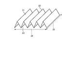
- FIG. 2 is a schematic perspective view showing an example of a filter medium for a powder coating filter of the present invention.
- FIG. 3 is a diagram for explaining a configuration of a test system for carrying out a collection performance test according to an embodiment of the present invention.
- the spunbonded non-woven fabric for a filter of the present invention is a non-woven fabric made of a thermoplastic continuous filament.
- the thermoplastic continuous filament is composed of a high melting point component and a low melting point component.
- FIG. 1 is a cross-sectional photograph of a spunbonded nonwoven fabric for a filter according to an embodiment of the present invention.
- the filter spunbonded non-woven fabric shown in FIG. 1 is ventilated from top to bottom during use.
- the spunbonded non-woven fabric for a filter is partially fused, has a rigidity of 15 mN or more and 30 mN or less in the MD direction of the non-woven fabric, and is fused with the non-fused convex portion 11. It has a recess 12 and a recess 12.
- the distances are (t C ) and (t D ) (t C ⁇ t D ), respectively, and the span-bonded non-woven fabric for a filter has the following relationship. 0.05 ⁇ 1-t B / t A ⁇ 0.50 ⁇ ⁇ ⁇ (1) 0.2 ⁇ t C / t D ⁇ 1.0 ...
- the MD direction refers to the sheet transporting direction at the time of manufacturing the spunbonded nonwoven fabric for a filter, that is, the winding direction in the nonwoven fabric roll
- the CD direction is the sheet conveying direction, that is, the winding direction in the nonwoven fabric roll. It refers to the direction of vertical intersection in. If the spunbonded non-woven fabric is not in the rolled state due to cutting or the like, the MD direction and the CD direction are determined by the following procedure. (A) In the plane of the spunbonded non-woven fabric, an arbitrary direction is determined, and a test piece having a length of 38.1 mm and a width of 25.4 mm is collected along that direction.
- test piece having a length of 38.1 mm and a width of 25.4 mm is collected in the directions rotated by 30, 60, and 90 degrees from the collecting direction.
- C The rigidity and softness of each test piece is measured based on the method for measuring the rigidity and softness of the spunbonded non-woven fabric described later for the test pieces in each direction.
- D The direction in which the value obtained by the measurement is the highest is the MD direction of the spunbonded non-woven fabric, and the direction orthogonal to this is the CD direction.
- FIG. 2 is a schematic perspective view showing an example of a filter medium for a powder coating filter of the present invention.
- the filter medium 21 for a powder coating filter shown in FIG. 2 has a peak portion 22 and a valley portion 23 formed by folding back a spunbonded non-woven fabric.
- the ridgeline of the mountain portion 22 is used. It is assumed that the parallel direction (broken arrow 25) is the CD direction and the direction orthogonal to the CD direction (broken arrow 24) is the MD direction.
- the air flow rate q (cm 3 / (cm 2 ⁇ sec)) / (g / m 2 ) per unit grain satisfies the following formula (3). The details of these will be described below. 0.05 ⁇ q ⁇ 0.50 ⁇ ⁇ ⁇ (3)
- Polyester is particularly preferably used as the thermoplastic resin which is a raw material of the thermoplastic continuous filament constituting the spunbonded nonwoven fabric for a filter of the present invention.
- Polyester is a polymer polymer having an acid component and an alcohol component as monomers.
- aromatic carboxylic acids such as phthalic acid (ortho), isophthalic acid and terephthalic acid, aliphatic dicarboxylic acids such as adipic acid and sebacic acid, and alicyclic dicarboxylic acids such as cyclohexanecarboxylic acid are used.
- the alcohol component ethylene glycol, diethylene glycol, polyethylene glycol and the like can be used.
- polyester examples include polyethylene terephthalate (PET), polybutylene terephthalate (PBT), polytrimethylene terephthalate (PTT), polyethylene naphthalate, polylactic acid, polybutylene succinate, and the like, which will be described later.
- PET polyethylene terephthalate
- PBT polybutylene terephthalate
- PTT polytrimethylene terephthalate
- polyethylene naphthalate polylactic acid
- polybutylene succinate and the like
- polyester raw materials include crystal nucleating agents, matting agents, pigments, fungicides, antibacterial agents, flame retardants, metal oxides, aliphatic bisamides and / or fats as long as the effects of the present invention are not impaired.
- Additives such as group monoamides and hydrophilic agents can be added.
- metal oxides such as titanium oxide improve spinnability by reducing surface friction of fibers and preventing fusion between fibers, and also increase thermal conductivity during fusion molding by a thermal roll of a non-woven fabric. This has the effect of improving the meltability of the non-woven fabric.
- aliphatic bisamides such as ethylene bisstearic acid amide and / or alkyl-substituted aliphatic monoamides have the effect of enhancing the releasability between the thermal roll and the non-woven fabric web and improving the transportability.
- thermoplastic continuous filament constituting the spunbonded nonwoven fabric for a filter of the present invention is composed of a high melting point component and a low melting point component.
- the thermoplastic continuous filament is a polyester which is a low melting point component having a melting point of 10 ° C. or more and 140 ° C. or less lower than the melting point of the polyester-based high melting point polymer around the polyester-based high melting point polymer which is a high melting point component. It is preferable that the filament is a composite filament in which a low melting point polymer is arranged.
- the spunbonded nonwoven fabric when the spunbonded nonwoven fabric is formed by fusion, the composite polyester fibers (filaments) constituting the spunbonded nonwoven fabric are firmly fused to each other, so that the spunbonded nonwoven fabric for the filter has excellent mechanical strength. It can withstand dust treatment under high air volume.
- the melting point of the thermoplastic resin is determined by using a differential scanning calorimeter (for example, "DSC-2" type manufactured by Perkin Elmer Co., Ltd.) at a heating rate of 20 ° C./min and a measurement temperature range of 30 ° C.
- the melting point of the thermoplastic resin is defined as the temperature at which an extreme value is given in the obtained melting heat absorption curve measured under the condition of 300 ° C. Further, for a resin whose melting endothermic curve does not show an extreme value in a differential scanning calorimeter, it is heated on a hot plate and the temperature at which the resin is melted by microscopic observation is defined as the melting point.
- polyester-based high-melting-melting polymer / polyester-based low-melting-melting polymer examples include combinations of PET / PBT, PET / PTT, PET / polylactic acid, PET / copolymerized PET, and the like.
- PET / copolymerized PET has excellent spinnability.
- the combination is preferably used.
- isophthalic acid copolymerized PET is preferably used because it is particularly excellent in spinnability.
- Examples of the composite form of the composite filament include a concentric sheath type, an eccentric sheath type, and a sea island type. Among them, the concentric sheath type can be used because the filaments can be fused uniformly and firmly. Is preferable.
- examples of the cross-sectional shape of the composite filament include a circular cross section, a flat cross section, a polygonal cross section, a multi-leaf cross section, and a hollow cross section. Among them, it is preferable to use a filament having a circular cross section as the cross-sectional shape.
- the composite filament for example, there is a method of mixing a fiber made of a polyester-based high melting point polymer and a fiber made of a polyester-based low melting point polymer, but in the case of the mixed fiber method, the fibers are uniform. It is difficult to fuse, for example, where fibers made of polyester-based refractory polymer are densely packed, the fusion becomes weak, and the mechanical strength and rigidity are inferior, which makes it unsuitable as a pleated filter.
- the melting point of the polyester-based low melting point polymer in the present invention is preferably 10 ° C. or higher and 140 ° C. or lower lower than the melting point of the polyester-based high melting point polymer.
- the melting point of the polyester-based low melting point polymer is 140 ° C. or lower, preferably 120 ° C. or lower, more preferably 100 ° C. or lower than the melting point of the polyester-based high melting point polymer, so that the heat resistance of the spunbonded non-woven fabric for a filter is reduced. Can be suppressed.
- the melting point of the polyester-based high melting point polymer is preferably in the range of 200 ° C. or higher and 320 ° C. or lower.
- the melting point of the polyester-based high melting point polymer is preferably 200 ° C. or higher, more preferably 210 ° C. or higher, and further preferably 220 ° C. or higher.
- a powder coating filter having excellent heat resistance can be obtained.
- the melting point of the polyester-based high melting point polymer to preferably 320 ° C. or lower, more preferably 300 ° C. or lower, and further preferably 280 ° C. or lower, a large amount of thermal energy for melting during the production of the non-woven fabric is consumed for production. It is possible to suppress the deterioration of the sex.
- the melting point of the polyester-based low melting point polymer is preferably in the range of 160 ° C. or higher and 250 ° C. or lower.
- a step of applying heat during pleating filter manufacturing such as heat setting during pleating, is performed. Excellent morphological stability even after passing.
- a powder coating filter having excellent meltability during the production of a non-woven fabric and excellent mechanical strength can be obtained. Can be done.
- the content ratio of the polyester-based high melting point polymer and the polyester-based low melting point polymer in the thermoplastic continuous filament is preferably in the range of 90:10 to 60:40 in terms of mass ratio, and is preferably in the range of 85:15 to 70: A range of 30 is a more preferred embodiment.
- the polyester-based refractory polymer By setting the polyester-based refractory polymer to 60% by mass or more and 90% by mass or less, the rigidity and heat resistance of the spunbonded non-woven fabric for a filter can be improved.
- the low melting point polyester is 10% by mass or more and 40% by mass or less to form a spunbonded non-woven fabric for a filter by fusion
- the composite polyester fibers (filaments) constituting the spunbonded non-woven fabric for a filter are used. Can be firmly fused, has excellent mechanical strength, and can sufficiently withstand dust collection under high air volume.
- Examples of the composite form of the composite polyester fiber include a concentric sheath type, an eccentric core sheath type, and a sea-island type. Among them, the composite form is capable of uniformly and firmly fusing the filaments to each other. A concentric sheath type is preferable.
- examples of the cross-sectional shape of the filament (single fiber) include a circular cross section, a flat cross section, a polygonal cross section, a multi-leaf cross section, and a hollow cross section. Among them, it is preferable to use a filament (single fiber) having a circular cross section as the cross-sectional shape.
- the average single fiber diameter of the thermoplastic continuous filament constituting the spunbonded nonwoven fabric for a filter of the present invention is in the range of 12 ⁇ m or more and 26 ⁇ m or less.
- the average single fiber diameter of the thermoplastic continuous filament is set to 12 ⁇ m or more, preferably 13 ⁇ m or more, more preferably 14 ⁇ m or more, the air permeability of the spunbonded non-woven fabric for a filter can be improved and the pressure loss can be reduced. It is also possible to reduce the number of yarn breaks when forming the thermoplastic continuous filament and improve the stability during production.
- the average single fiber diameter of the thermoplastic continuous filament is 26 ⁇ m or less, preferably 25 ⁇ m or less, more preferably 24 ⁇ m or less, the uniformity of the spunbonded non-woven fabric for filtration is improved and the surface of the non-woven fabric is made dense. This can improve the collection performance, such as making it easier to filter dust on the surface layer.
- the average single fiber diameter ( ⁇ m) of the spunbonded nonwoven fabric for a filter is a value obtained by the following method.
- (I) Randomly collect 10 small piece samples from the spunbonded non-woven fabric for the filter.
- (Ii) Take a photograph of the surface of the collected small piece sample with a scanning electron microscope or the like capable of measuring the fiber thickness in the range of 500 to 2000 times.
- (Iii) A total of 100 fibers, 10 fibers each, are arbitrarily selected from the photographs taken of each small piece sample, and the thickness thereof is measured. The fiber is assumed to have a circular cross section, and the thickness is the single fiber diameter.
- (Iv) The value calculated by rounding off the first decimal place of those arithmetic mean values was taken as the average single fiber diameter.
- the spunbonded nonwoven fabric for a filter of the present invention is produced by sequentially performing the following steps (a) to (c).
- C A step of partially fusing the obtained fiber web. Further details of each of the above steps will be described below.
- thermoplastic continuous filament forming step the thermoplastic polymer is melt-extruded from the spinneret.
- thermoplastic continuous filament a composite filament in which a polyester-based low-melting-melting polymer having a melting point lower than the melting point of the polyester-based high-melting-melting polymer is arranged around the polyester-based high-melting-melting polymer is used as the thermoplastic continuous filament, there is no case.
- a polyester-based high-melting point polymer and a polyester-based low-melting-melting polymer are melted at a temperature equal to or higher than the melting point (melting point + 70 ° C.), respectively, and around the polyester-based high-melting-melting polymer, the melting point of the polyester-based high-melting-melting polymer
- a composite filament in which a polyester-based low melting point polymer having a low melting point of 10 ° C. or higher and 140 ° C. or lower is arranged, air is spun from the pores with a spinning mouthpiece having a base temperature of 10 ° C. or higher and 140 ° C. or lower.
- a filament having a circular cross section is spun by pulling and stretching at a spinning speed of 4000 m / min or more and 6000 m / min or less by soccer.
- the non-woven fabric of the present invention is a so-called spunbonded non-woven fabric for a filter, and the spun thermoplastic continuous filament is sucked by an ejector and sprayed from an open fiber plate having a slit shape at the lower part of the ejector. It has a step of depositing on a moving net conveyor to obtain a fibrous web.
- the spunbonded non-woven fabric for a filter made of the above filament (long fiber) is used. By doing so, the rigidity and mechanical strength can be increased as compared with the case of a non-woven fabric made of short fibers composed of discontinuous fibers, which can be preferable as a powder coating filter. ..
- the temperature of fusion for temporary fusion is preferably 70 ° C. or higher and 120 ° C. or lower lower than the melting point of the polyester-based low melting point polymer.
- the linear pressure for temporary fusion is preferably 30 kg / cm or more and 70 kg / cm or less.
- the linear pressure for temporary fusion is preferably 30 kg / cm or more and 70 kg / cm or less.
- the spunbonded nonwoven fabric for a filter of the present invention is partially fused, but the method of partial fusion is not particularly limited.
- the partial fusion step is preferably processed continuously from the web forming step. By continuing the processing from the web forming step, the density of the fused portion can be increased, and a non-woven fabric having a waist strength excellent in pleated formability can be obtained as a spunbonded non-woven fabric for a filter.
- Fusion by a thermal emboss roll or fusion by a combination of an ultrasonic oscillator and an emboss roll is preferable. In particular, fusion by heat embossing roll is most preferable from the viewpoint of improving the strength of the non-woven fabric.
- the temperature of fusion by the thermal embossing roll is preferably 5 ° C. or higher and 60 ° C. or lower lower than the melting point of the polymer having the lowest melting point existing on the fiber surface of the non-woven fabric, and more preferably 10 ° C. or higher and 50 ° C. or lower. Excessive fusion can be prevented by setting the temperature difference of the melting points of the polymer having the lowest melting point existing on the fiber surface of the non-woven fabric by thermal embossing to 5 ° C. or higher, more preferably 10 ° C. or higher. On the other hand, by setting the temperature difference of the melting points to 60 ° C. or lower, more preferably 50 ° C. or lower, uniform fusion can be performed in the non-woven fabric.
- the linear pressure for fusion is preferably 30 kg / cm or more and 90 kg / cm or less.
- the linear pressure for fusion is preferably 30 kg / cm or more, more preferably 40 kg / cm or more, it is possible to impart the mechanical strength required for pleating processability to the non-woven fabric when used as a spunbonded non-woven fabric for a filter. it can. Excessive fusion can be prevented by setting the linear pressure for fusion to 90 kg / cm or less, more preferably 80 kg / cm or less.
- the ratio of the fusion area of the partial fusion of the spunbonded nonwoven fabric for the filter of the present invention occupies the entire area of the nonwoven fabric of the fusion portion (recess). It is a ratio, and is preferably 5% or more and 20% or less with respect to the total area of the non-woven fabric.
- the fused area ratio is 5% or more, more preferably 6% or more, still more preferably 8% or more, sufficient strength of the non-woven fabric can be obtained, and the surface does not easily fluff.
- the fused area ratio is 20% or less, more preferably 19% or less, still more preferably 18% or less, the voids between the fibers are reduced, the pressure loss is increased, and the collection performance may be lowered. Absent.
- a digital microscope for example, "VHX-5000" manufactured by Keyence Co., Ltd.
- VHX-5000 manufactured by Keyence Co., Ltd.
- the fused area ratio (%) is calculated by rounding off the first digit after the decimal point as a percentage.
- the area (cm 2 ) of the fused portion in the rectangular frame is divided by 1.0 cm 2 , which is the area of the rectangular frame, and then the third decimal place is rounded off.
- the landing area ratio can be calculated.
- the fused portion forms a recess, and the thermoplastic continuous filaments constituting the non-woven fabric are fused by heat and pressure. That is, the portion where the thermoplastic continuous filaments are fused and aggregated as compared with the other portions is the fused portion.
- the portion where the thermoplastic continuous filaments are fused and aggregated as compared with the other portions is the fused portion.
- the portion where the thermoplastic continuous filament is fused and aggregated by the convex portion of the emboss roll becomes the fusion portion.
- the fused portion is a convex portion of the roll having unevenness and a flat roll.
- the portion where the thermoplastic continuous filaments of the non-woven fabric are aggregated by being fused with and is composed of a pair of upper rolls and lower rolls in which a plurality of linear grooves arranged in parallel are formed on the surface, and the grooves of the upper roll and the grooves of the lower roll intersect at a certain angle.
- the fused portion means a portion where the thermoplastic continuous filaments of the non-woven fabric are aggregated by being fused by the convex portion of the upper roll and the convex portion of the lower roll.
- the portion fused between the upper convex portion and the lower concave portion or the upper concave portion and the lower convex portion is not included in the fusion portion referred to here.
- the area of each fused portion is preferably 0.3 mm 2 or more and 5.0 mm 2 or less.
- the thickness is preferably 0.3 mm 2 or more and 5.0 mm 2 or less.
- the shape of the fused portion in the spunbonded non-woven fabric for a filter of the present invention is not particularly specified, and a roll having a predetermined pattern of unevenness is used only on the upper side or the lower side, and the other rolls are flat rolls without unevenness.
- a roll having a predetermined pattern of unevenness is used only on the upper side or the lower side, and the other rolls are flat rolls without unevenness.
- the shape of the fused portion is circular, triangular, quadrangular, or parallelogram. , Oval, rhombus, etc.
- the arrangement of these fused portions is not particularly specified, and may be regularly arranged at equal intervals, randomly arranged, or a mixture of different shapes. Among them, from the viewpoint of uniformity of the non-woven fabric, it is preferable that the fused portions are arranged at equal intervals. Further, in that the non-woven fabric is partially fused without peeling, it is composed of a pair of upper rolls and lower rolls in which a plurality of linear grooves arranged in parallel are formed on the surface of the upper roll. A parallelogram formed by fusing the convex portion of the upper roll and the convex portion of the lower roll using an embossed roll provided so that the groove and the groove of the lower roll intersect at a certain angle. The fused portion is preferable.
- the spunbonded nonwoven fabric for filter of the present invention has a rigidity of 15 mN or more and 30 mN or less in the MD direction of the non-woven fabric.
- the rigidity is 15 mN or more, more preferably 17 mN or more, and further preferably 20 mN or more
- pleating can be performed while maintaining the strength and shape retention of the non-woven fabric.
- it is 30 mN or less, more preferably 29 mN or less, and further preferably 28 mN or less, the folding resistance during pleating is relaxed, and the pleated mountain valley shape is sharply finished.
- the longitudinal direction of the non-woven fabric is the vertical direction of the sample.
- the thickness (t A ) from one surface of the convex portion to the other surface and the thickness (t B ) from one surface of the concave portion to the other surface in the cross section of the nonwoven fabric are the above formulas (1).
- the value of the above formula (1) is 0.05 or more, more preferably 0.10 or more, still more preferably 0.15 or more, the fusion between the fibers becomes strong and the fiber is used as a powder coating filter. Excellent shape retention can be obtained even under high flow rate.
- the fused portion and the non-fused portion coexist in the non-woven fabric, and the non-woven fabric is ventilated.
- a non-woven fabric having a good balance between properties and rigidity can be obtained.
- the distances from one surface of the convex portion to one surface of the concave portion in the cross section of the nonwoven fabric are (t C ) and (t D ) (t C ⁇ t D ), respectively, and the above formula (2) It is a spunbonded non-woven fabric for a filter having a relationship of.
- the value of the above equation (2) is 0.20 or more, more preferably 0.25 or more, and further preferably 0.30 or more, the unevenness of the non-woven fabric becomes small, and the mountain valley shape of the pleats becomes sharp during pleating. Finished.
- the fused portion and the specific fused portion coexist in the non-woven fabric, and the non-woven fabric is ventilated.
- a non-woven fabric having a good balance between properties and rigidity can be obtained.
- the distances from one surface of the convex portion to one surface of the concave portion (t C ), (t D ) (t C ⁇ t D ) and the values of the above equation (2) are obtained as follows. The value will be adopted.
- any fusion portion (recess), the intersection of the center line in the MD direction and the center line in the CD direction is set as the center point of the fusion portion (recess).
- a straight line is drawn that passes through the center point of the fused portion (recess) and is parallel to the CD direction.
- the area surrounded by the 1.0 cm ⁇ 1.0 cm square formed by (i) to (iii) is cut with a razor blade.
- t A Distance between the tops of non-fused parts (convex parts) from one surface to the other surface
- t B Distance between the tops of fused parts (concave parts) from one surface to the other surface
- t D One surface Distance between the top of the non-fused part (convex part) and the top of the fused part (concave part) (t C ⁇ t D )
- Viii The ratio of t B / t A and t C / t D is calculated from the measurement result.
- Ix Calculate the arithmetic mean value of t B / t A and t C / t D obtained from each measurement sample, and adopt the value obtained by rounding off the third decimal place.
- the basis weight of the spunbonded non-woven fabric for a filter in the present invention is preferably in the range of 150 g / m 2 or more and 300 g / m 2 or less.
- the basis weight is 150 g / m 2 or more, the rigidity required for pleats can be obtained, which is preferable.
- the basis weight is 300 g / m 2 or less, preferably 270 g / m 2 or less, more preferably 260 g / m 2 or less, it is possible to suppress an increase in pressure loss, which is also preferable in terms of cost.
- the basis weight here is to collect three samples with a size of 50 cm in length and 50 cm in width, measure each mass, convert the average value of the obtained values per unit area, and place the first decimal place. Obtained by rounding.
- the basis weight CV value of the spunbonded non-woven fabric for a filter of the present invention is preferably 5% or less. If the basis weight CV value is preferably 4.8% or less, and more preferably 4.5% or less, the non-woven fabric can be made denser as the uniformity of the non-woven fabric is improved, so that the collection efficiency is improved. This is preferable because the filter life is improved and a satisfactory filter life can be easily obtained. On the other hand, it is more preferable that the basis weight CV value is 1% or more because the life of the filter is extended by securing a certain amount of airflow of the spunbonded non-woven fabric for the filter and reducing the pressure loss.
- the basis weight CV value (%) of the spunbonded nonwoven fabric for a filter a value obtained by measuring as follows is adopted.
- (I) Collect a total of 100 small pieces of 5 cm ⁇ 5 cm from the spunbonded non-woven fabric for the filter.
- (Ii) The mass (g) of each small piece is measured and converted per unit area (1 m 2). Convert the result of the average value of (iii) (ii) (W ave), and calculates the standard deviation (W sdv) respectively.
- (Iv) Calculate the basis weight CV value (%) by the following formula and round off to the second decimal place.
- Basis weight CV value (%) W sdv / W ave ⁇ 100
- the thickness of the spunbonded non-woven fabric for a filter in the present invention is preferably 0.50 mm or more and 0.80 mm or less, and more preferably 0.51 mm or more and 0.78 mm or less.
- the thickness is preferably 0.50 mm or more and 0.80 mm or less, and more preferably 0.51 mm or more and 0.78 mm or less.
- the thickness (mm) of the spunbonded nonwoven fabric for a filter shall be a value obtained by measuring by the following method.
- a thickness gauge for example, "TECLOCK” (registered trademark) SM-114 manufactured by Teclock Co., Ltd.
- the thickness of the non-woven fabric is measured at 10 points at equal intervals in the CD direction.
- the thickness of the non-woven fabric (mm) is obtained by rounding off the third decimal place from the above arithmetic mean value.
- the apparent density of the spunbonded nonwoven fabric for filters in the present invention is preferably 0.25 g / cm 3 or more and 0.40 g / cm 3 or less.
- the apparent density is 0.25 g / cm 3 or more and 0.40 g / cm 3 or less, the spunbonded non-woven fabric has a dense structure, and dust does not easily enter the inside, and the dust removal property is excellent.
- a more preferable range of apparent density is 0.26 g / cm 3 or more and 0.38 g / cm 3 or less.
- the air permeability per unit grain of the spunbonded non-woven fabric for filters in the present invention is 0.05 ((cm 3 / (cm 2 ⁇ sec)) / (g / m 2 )) or more and 0.50 ((cm 3 / ()). It is preferably cm 2 ⁇ sec)) / (g / m 2 )) or less.
- the air flow rate per unit is 0.05 ((cm 3 / (cm 2 ⁇ s)) / (g / m 2 )) or more, preferably 0.06 ((cm 3 / (cm 2 ⁇ s))). When it is / (g / m 2 )) or more, it is possible to suppress an increase in pressure loss.
- the air flow rate per unit is 0.50 ((cm 3 / (cm 2 ⁇ sec)) / (g / m 2 )) or less, preferably 0.48 ((cm 3 / (cm 2 ⁇ sec)). )) / (G / m 2 )) or less, the dust is less likely to stay inside, and the dust removal property is good.
- the air flow rate ((cm 3 / (cm 2 ⁇ sec)) / (g / m 2 )) per unit of the spunbonded non-woven fabric for the filter is as follows: JIS L1913: 2010 “General non-woven fabric”. The value obtained by dividing the value measured based on the 6.8.1 “Frazil type method” of "Test method” 6.8 "Breathability (JIS method)" by the above-mentioned scale shall be adopted. (I) Collect 10 test pieces of 150 mm in length ⁇ 150 mm in width at equal intervals in the CD direction of the spunbonded non-woven fabric.
- the spunbonded non-woven fabric for a filter of the present invention has both a balance between dust collection performance and air permeability, has high rigidity, and has excellent fluff resistance.
- the contained dust air can be suitably used as powder coating filter powder coating booth 100 ⁇ 2000 m 3 processed per minute.
- a powder coating filter is, for example, a cylindrical type in which the upper end and the lower end of the cylinder are fixed after the spunbonded non-woven fabric for the filter is pleated and the whole is made into a cylinder around the axis of the element.
- the powder coating filter of the present invention uses the above-mentioned non-woven fabric for powder coating filter, and the powder coating filter is, for example, a forced air supply type (push-pull type) in which fans are attached to exhaust and intake air. , Used in natural air supply type powder coating booths with fans attached only to the exhaust.
- the powder coating filter of the present invention is a forced air supply type (push-pull type) powder that can keep the inside of the powder coating booth at a positive pressure by controlling the air supply and exhaust fans and prevent the intrusion of outside air from other than the air supply port. It can be suitably used for a body painting booth.
- the powder coating booth in which the powder coating filter of the present invention is used has an exhaust recycling system that recycles a part of the air exhausted from the powder coating booth and mixes it with the air taken in from the outside air. It may be a powder coating booth.
- the present invention will be specifically described based on Examples. However, the present invention is not limited to these examples. In addition, in the measurement of each physical property, if there is no particular description, the measurement is performed based on the above method.
- ⁇ is the viscosity of the polymer solution
- ⁇ 0 is the viscosity of orthochlorophenol
- t is the drop time of the solution (seconds)
- d is the density of the solution (g / cm 3 )
- t 0 is the drop of orthochlorophenol.
- Time (seconds) and d 0 represent the density of orthochlorophenol (g / cm 3 ), respectively.
- the intrinsic viscosity (IV) was calculated from the relative viscosity ⁇ r by the following formula.
- -Intrinsic viscosity (IV) 0.0242 ⁇ r +0.2634
- Average single fiber diameter ( ⁇ m) The average single fiber diameter of the non-woven fabric was calculated by the above method using a scanning electron microscope of "VHX-D500" manufactured by KEYENCE CORPORATION.
- Thickness of spunbonded non-woven fabric for filter (mm)
- "TECLOCK” registered trademark
- SM-114 manufactured by Teklock Co., Ltd. was used and evaluated by the above method.
- Sheet cross-sectional thickness (mm) of spunbonded non-woven fabric for filters As a scanning electron microscope, "VHX-D500" manufactured by KEYENCE CORPORATION was used, and the measurement was carried out by the above method.
- Pleating processability of spunbonded non-woven fabric for filter (1) The spunbonded non-woven fabric for filter is cut to a width of 240 mm, and the top of the pleated molded body is compressed by heating the spunbonded non-woven fabric for filter to 150 ° C. A pleated molded body was obtained by pleating so that the distance from the ridge line of the above to the ridge line of the next apex was 35 mm. (2) This pleated molded product is wound around a porous cylindrical core made of polypropylene by 45 threads, the ends of the pleated molded product are heat-sealed, and then caps made by injection molding are fused to both ends on the cylindrical shape. A pleated filter was prepared.
- Fluffing (dots) of spunbonded non-woven fabric for filters (1) A total of 10 samples with a length in the MD direction x a length of 250 mm x 25 mm in the CD direction from the spunbonded non-woven fabric for the filter, 5 points at equal intervals in the CD direction of the spunbonded non-woven fabric for the filter, and 1 each on the front and back of the non-woven fabric Cut out a sheet.
- the CD direction is a direction orthogonal to the MD direction.
- the material is worn with a load of 300 gf and a number of times of wear of 200 reciprocations.
- the fluffing on the surface of the spunbonded non-woven fabric for the filter was judged on a 5-point scale based on the following criteria based on the texture when 20 panelists visually and touched the spunbonded non-woven fabric for the filter after the test.
- the total score judged by each panelist was used to evaluate the fluffiness of the spunbonded non-woven fabric for filters. Therefore, the total score increased from a minimum of 0 to a maximum of 100, and a score of 80 or higher was judged to be acceptable.
- 5 points Very good (the surface of the spunbonded non-woven fabric for the filter is not fluffed, and the surface of the spunbonded non-woven fabric for the filter has a smooth feel when touched with a finger, and there is no resistance to the finger.) 4 points: Good (between 5 and 3 points) 3 points: Normal (There is no fluff on the surface of the spunbonded non-woven fabric for the filter, but when touched with a finger, the surface of the spunbonded non-woven fabric for the filter has a rough feel, and the finger feels resistance.) 2 points: Bad (between 3 points and 1 point) 1 point: Very bad (fluffing occurs on the surface of the spunbonded non-woven fabric for the filter, and when touched with a finger, the surface of the spunbonded non-woven fabric for the filter has a rough feel, and the finger feels resistance).
- FIG. 3 is a diagram for explaining a configuration of a test system for carrying out a collection performance test according to an embodiment of the present invention.
- the test system 31 shown in FIG. 3 includes a sample holder 32 for setting the test sample M, a flow meter 33, a flow rate adjusting valve 34, a blower 35, a dust supply device 36, a switching cock 37, and a particle counter 38. To be equipped.
- the flow meter 33, the flow rate adjusting valve 34, the blower 35, and the dust supply device 36 are connected to the sample holder 32.
- the flow meter 33 is connected to the blower 35 via the flow rate adjusting valve 34.
- Dust is supplied to the sample holder 32 from the dust supply device 36 by the intake air of the blower 35.
- a particle counter 38 is connected to the sample holder 32, and the number of dusts on the upstream side and the number of dusts on the downstream side of the test sample M can be measured via the switching cock 37, respectively.
- three 15 cm ⁇ 15 cm samples are collected from an arbitrary part of the non-woven fabric, and the collected test sample M is set in the sample holder 32.
- the evaluation area of the test sample was 115 cm 2 .
- a polystyrene 0.309U 10 wt% solution manufactured by Nacalai Tesque, Inc.
- the air volume is adjusted by the flow rate adjusting valve 34 so that the filter passing speed is 3.0 m / min, and the dust concentration is 20,000 to 70,000 / (2.83 ⁇ 10 -4 m 3 (0.01 ft 3 )).
- the number of dust upstream and the number of dust downstream of the test sample M were measured with a particle counter 38 (manufactured by Rion Co., Ltd., KC-01D) in the range of dust particle size of 0.3 to 0.5 ⁇ m. ..
- the obtained value was substituted into the following formula, and the first decimal place of the calculated value was rounded off to obtain the collection performance (%).
- Collection performance (%) [1- (D1 / D2)] x 100
- D1 the number of dusts downstream (total of 3 times)
- D2 the number of dusts upstream (total of 3 times).
- -Polyester resin A Polyethylene terephthalate (PET) dried to a moisture content of 50 mass ppm or less, having an intrinsic viscosity (IV) of 0.65 and a melting point of 260 ° C.
- Polyester resin B Copolymerized polyethylene terephthalate (CO-PET) dried to a moisture content of 50 mass ppm or less, having an intrinsic viscosity (IV) of 0.64, an isophthalic acid copolymerization rate of 11 mol%, and a melting point of 230 ° C.
- a filament having a circular cross-sectional shape was spun at a speed of 4900 m / min, and the fiber arrangement was regulated and deposited by a fiber-spreading plate on a moving net conveyor, and a fiber web composed of fibers having a single fiber diameter of 14.8 ⁇ m was collected.
- the collected fiber webs were tentatively fused to the collected fiber webs by a calendar roll composed of a pair of flat rolls under the conditions of a temperature of 140 ° C. and a linear pressure of 50 kg / cm. Further, subsequently, by embossing rolls composed of a pair of engraving rolls having a fused area ratio of 10% and an area of 1.6 mm 2 per fused portion, the upper and lower temperatures are 200 ° C. and the linear pressure is 70 kg / cm. By fusing under the conditions, a spunbonded non-woven fabric for a filter having a basis weight of 200 g / m 2 was obtained.
- the sheet cross-sectional thicknesses of 1-t B / t A and t C / t D of the obtained spunbonded non-woven fabric for filter were 0.39 and 0.84, respectively, and the basis weight CV value was 3.3% and the thickness.
- the span is 0.70 mm
- the rigidity in the MD direction is 27 mN
- the air flow rate (q) per unit basis weight is 0.11 (cm 3 / (cm 2 ⁇ sec)) / (g / m 2 ). It was.
- Table 1 The results are shown in Table 1.
- Example 2 A spunbonded non-woven fabric for a filter having a basis weight of 200 g / m 2 was obtained under the same conditions as in Example 1 except that the upper and lower embossed rolls made of engraving rolls were fused at 180 ° C.
- the sheet cross-sectional thicknesses of the obtained spunbonded non-woven fabric were 1-t B / t A and t C / t D , respectively, 0.46 and 0.50, the basis weight CV value was 3.4%, and the thickness was The rigidity and softness in the MD direction was 0.91 mm, and the air flow rate (q) per unit basis weight was 0.13 (cm 3 / (cm 2 ⁇ sec)) / (g / m 2 ).
- Table 1 The results are shown in Table 1.
- the upper and lower embossed rolls are made of a pair of engraving rolls having a fused area ratio of 10% and an area of 1.6 mm 2 per fused portion, and the fused area ratio is 18% and the fused portion 1 is formed.
- a spunbonded non-woven fabric for use was obtained.
- the sheet cross-sectional thicknesses 1-t B / t A and t C / t D of the obtained spunbonded non-woven fabric were 0.48 and 0.85, respectively, the basis weight CV value was 4.8%, and the thickness was The rigidity and softness in the MD direction was 0.54 mm, and the air flow rate (q) per unit basis weight was 0.10 (cm 3 / (cm 2 ⁇ sec)) / (g / m 2 ). The results are shown in Table 1.
- the upper and lower embossed rolls are made of a pair of engraving rolls having a fused area ratio of 10% and an area of 1.6 mm 2 per fused portion, and the fused area ratio is 6% and the fused portion 1 is formed.
- a spunbonded non-woven fabric for a filter having a grain size of 200 g / m 2 was obtained under the same conditions as in Example 1 except that it was used instead of an embossed roll composed of a pair of engraving rolls having an area of 1.6 mm 2 per piece. ..
- the sheet cross-sectional thicknesses 1-t B / t A and t C / t D of the obtained spunbonded non-woven fabric were 0.47 and 0.71, respectively, the basis weight CV value was 3.5%, and the thickness was The rigidity and softness in the MD direction was 0.82 mm, and the air flow rate (q) per unit basis weight was 0.14 (cm 3 / (cm 2 ⁇ sec)) / (g / m 2 ). The results are shown in Table 1.
- Example 5 While the spinning speed was changed so that the average single fiber diameter was 24.6 ⁇ m, the basis weight was changed under the same conditions as in Example 1 except that the speed of the net conveyor was changed to make the basis weight the same as in Example 1. A 200 g / m 2 filter spunbonded non-woven fabric was obtained. The sheet cross-sectional thicknesses 1-t B / t A and t C / t D of the obtained spunbonded non-woven fabric were 0.46 and 0.89, respectively, and the basis weight CV value was 4.3% and the thickness was 0.
- the rigidity and softness in the MD direction was .90 mm, and the air flow rate (q) per unit basis weight was 0.15 (cm 3 / (cm 2 ⁇ sec)) / (g / m 2 ).
- the results are shown in Table 1.
- the characteristics of the obtained non-woven fabric are as shown in Table 1. All of the spunbonded non-woven fabrics of Examples 1 to 5 have a vertical rigidity and softness of 15 mN or more, a basis weight CV value of 11% or less, and a pressure loss of 30 Pa or less. It was excellent in rigidity and basis weight uniformity, and showed good characteristics as a spunbonded non-woven fabric for a filter. In addition, the results of the pleating processability and the fluffing property were also good, with the pleating processability being 87 points or more and the fluffing property being 85 points or more. The results are shown in Table 1.
- Example 1 In the manufacturing process of Example 1, after the sheet obtained in the temporary fusion step is once wound between the step of temporarily fusionizing the collected fiber web and the step of fusion using an embossed roll. Examples except that the step of cooling to room temperature and feeding this sheet to the embossed roll is provided, that is, the step of fusing using the embossed roll is not performed following the temporary fusing step. Under the same conditions as in No. 1, a spunbonded non-woven fabric for a filter having a grain size of 200 g / m 2 was obtained.
- the sheet cross-sectional thicknesses of 1-t B / t A and t C / t D of the obtained spunbonded non-woven fabric for filter were 0.59 and 0.45, respectively, and the basis weight CV value was 5.9% and the thickness.
- the span was 0.66 mm, the rigidity in the MD direction was 32 mN, and the air flow rate (q) per unit basis weight was 0.10 (cm 3 / (cm 2 ⁇ sec)) / (g / m 2 ). ..
- the results are shown in Table 2.
- the upper and lower embossed rolls are made of a pair of engraving rolls having a fused area ratio of 10% and an area of 1.6 mm 2 per fused portion, and the fused area ratio is 24% and the fused portion 1 is formed.
- a spunbonded non-woven fabric for a filter having a grain size of 200 g / m 2 was obtained under the same conditions as in Example 1 except that it was used instead of an embossed roll composed of a pair of engraving rolls having an area of 1.6 mm 2 per piece. ..
- the sheet cross-sectional thicknesses 1-t B / t A and t C / t D of the obtained spunbonded non-woven fabric were 0.65 and 0.55, respectively, and the basis weight CV value was 3.2% and the thickness was 0.
- the rigidity and softness in the MD direction was .63 mm, and the air flow rate (q) per unit basis weight was 0.09 (cm 3 / (cm 2 ⁇ sec)) / (g / m 2 ).
- the results are shown in Table 2.
- Example 3 Under the same conditions as in Example 1 except that the discharge rate and spinning speed were changed so that the average single fiber diameter was 29.2 ⁇ m, while the speed of the net conveyor was changed to make the basis weight the same as in Example 1. , A spunbonded non-woven fabric for a filter having a basis weight of 200 g / m 2 was obtained.
- the sheet cross-sectional thicknesses 1-t B / t A and t C / t D of the obtained spunbonded non-woven fabric were 0.64 and 0.68, respectively, and the basis weight CV value was 5.2% and the thickness was 1.
- the rigidity and softness in the MD direction was .02 mm, and the air flow rate (q) per unit basis weight was 0.18 (cm 3 / (cm 2 ⁇ sec)) / (g / m 2 ).
- the results are shown in Table 2.
- Example 4 Under the same conditions as in Example 1 except that the discharge rate and spinning speed were changed so that the average single fiber diameter was 11.2 ⁇ m, while the speed of the net conveyor was changed to make the basis weight the same as in Example 1. , A spunbonded non-woven fabric for a filter having a basis weight of 200 g / m 2 was obtained.
- the sheet cross-sectional thicknesses 1-t B / t A and t C / t D of the obtained spunbonded non-woven fabric are 0.63 and 0.69, respectively, and the grain CV value is 2.6% and the thickness is 0.
- polyester-based resin A and the polyester-based resin B were melted at temperatures of 295 ° C. and 280 ° C., respectively.
- polyester resin A is used as a core component
- polyester resin B is used as a sheath component
- the base temperature is 300 ° C.
- a filament having a circular cross section is spun at a speed of 4400 m / min, the filament is made to collide with a metal collision plate installed at an air soccer outlet, and the fiber is charged and opened by friction charging, and the average single fiber diameter is 14.8 ⁇ m.
- a fiber web of fibers was collected on a moving net conveyor.
- the upper and lower temperatures are 205 ° C. and the linear pressure is 70 kg / cm. They were fused under the conditions to obtain a spunbonded non-woven fabric having a basis weight of 200 g / m 2.
- the sheet cross-sectional thicknesses 1-t B / t A and t C / t D of the obtained spunbonded non-woven fabric were 0.61 and 0.57, respectively, and the basis weight CV value was 12.1% and the thickness was 0.
- the rigidity and softness in the MD direction was .54 mm, and the air flow rate (q) per unit basis weight was 0.09 (cm 3 / (cm 2 ⁇ sec)) / (g / m 2 ).
- the results are shown in Table 2.
- Comparative Example 2 had high rigidity and softness of the non-woven fabric and was inferior in pleating workability, and Comparative Example 3 was inferior in rigidity and softness, pleating workability and fluffing property.
- Comparative Example 4 the rigidity and softness of the non-woven fabric was low, the air permeability per unit basis weight of the non-woven fabric was low, and the pleating workability was inferior.
- Comparative Example 5 the basis weight CV value of the non-woven fabric was high, and the pleating workability was inferior.
- the spunbonded non-woven fabric for a filter, the filter medium for a powder coating filter, and the powder coating filter of the present invention have both a balance between dust collection performance and air permeability, have high rigidity, and have excellent fluff resistance.
- the scope of application is not limited to this.
Abstract
The spunbond nonwoven fabric for filters according to the present invention is formed of thermoplastic continuous filaments comprising a high-melting-point component and a low-melting-point component, is partially fused, and has a non-fused protrusion portion and a fused recess portion. The thickness tA from one surface to the other surface of the protrusion portion in a cross-sectional surface of the nonwoven fabric, and the thickness tB from one surface to the other surface of the recess portion, and the respective distances tC, tD (tC<tD) from the surfaces of the protrusion portion to the surfaces of the recess portion, satisfy the relations represented by formulas (1) and (2). The air flow rate (q) (cm3/(cm2∙sec))/(g/m2) per unit basis weight of the spunbond nonwoven fabric satisfies formula (3). Formula (1): 0.05≤1-tB/tA<0.50
Formula (2): 0.2≤tC/tD<1.0
Formula (3): 0.05≤q≤0.50
Description
本発明は、剛性と通気性に優れたフィルター用スパンボンド不織布、粉体塗装フィルター用濾材および粉体塗装フィルターに関するものである。
The present invention relates to a spunbonded non-woven fabric for a filter having excellent rigidity and breathability, a filter medium for a powder coating filter, and a powder coating filter.
自動車ボディ等の粉体塗装ブースは、粉体塗装ブース天井面より空気が吸気され、粉体塗装ブース床面よりブース内の空気が排気されるような構造となっており、周囲作業場の環境に悪影響を与えないように、塗装する作業場をほぼ密閉して使用されている。一般に粉体塗装ブース内に供給される空気には外気から取り入れた空気が使用されており、粉体塗装ブース内に供給する空気は外気から取り入れた空気に含まれた塵や埃を完全に取り除くことが必要である。もし粉体塗装ブース内に供給する空気に塵や埃が少しでもあれば、それが塗装表面に付着して塗装品質の低下を招く。そのため、供給空気のクリーン化は極めて重要であり、粉体塗装ブースには供給空気の清浄化をはかるために粉体塗装フィルターが重要である。
Powder coating booths such as automobile bodies have a structure in which air is taken in from the ceiling surface of the powder coating booth and air inside the booth is exhausted from the floor surface of the powder coating booth. The painting workplace is used almost closed so as not to adversely affect it. Generally, the air supplied to the powder coating booth is the air taken in from the outside air, and the air supplied to the powder coating booth completely removes the dust and dirt contained in the air taken in from the outside air. It is necessary. If there is any dust or dirt in the air supplied to the powder coating booth, it will adhere to the coating surface and cause deterioration of coating quality. Therefore, cleanliness of the supply air is extremely important, and a powder coating filter is important for the powder coating booth to clean the supply air.
このような粉体塗装ブースフィルターの材料としては不織布が提案されており、特に空気流出面からの繊維・ダストの脱落を防止するために連続的な長繊維を部分的に融着した長繊維不織布をプリーツ加工したものが用いられている。例えば、特許文献1や2には熱可塑性連続フィラメントをあらかじめ一対のフラットロールで加熱圧接した後に一対の彫刻が施されたエンボスロールで部分的に融着した不織布が開示されている。また、特許文献3には、高融点成分の熱可塑性連続フィラメントと低融点成分の熱可塑性連続フィラメントとを混繊させた不織布や、高融点成分と低融点成分とからなる多葉型複合繊維からなる不織布が開示されている。粉体塗装ブースに使用されるフィルター用のスパンボンド不織布は、大量の空気を短時間で処理する通気性と、フィルターとしての比表面積を大きくするためのプリーツ加工性とが必要である。
Non-woven fabric has been proposed as a material for such a powder coating booth filter, and in particular, a long-fiber non-woven fabric in which continuous long fibers are partially fused in order to prevent fibers and dust from falling off from the air outflow surface. Is pleated. For example, Patent Documents 1 and 2 disclose a non-woven fabric in which thermoplastic continuous filaments are previously heat-pressed with a pair of flat rolls and then partially fused with a pair of engraved embossed rolls. Further, Patent Document 3 describes a non-woven fabric in which a thermoplastic continuous filament having a high melting point component and a thermoplastic continuous filament having a low melting point component are mixed, and a multi-leaf composite fiber composed of a high melting point component and a low melting point component. Non-woven fabric is disclosed. The spunbonded non-woven fabric for filters used in powder coating booths needs to have breathability to process a large amount of air in a short time and pleating workability to increase the specific surface area of the filter.
前記の粉体塗装フィルター用スパンボンド不織布は粉体塗装ブースで1分間あたりに100~2000m3の塵や埃を含んだ空気を処理し、処理をした空気を塗装ブース内に供給する必要がある。このような粉体塗装ブースで使用される粉体塗装フィルター用不織布には大量の空気を短時間で処理するための通気性とプリーツ形状保持性を有した剛性が必要である。ところで、従来の不織布は、剛性を高めた場合、粉体塗装フィルター用スパンボンド不織布として十分な通気性を有するものが得られない。すなわち、通気性を向上しようと繊維同士の融着を緩くした場合、不織布の剛性が低下し、プリーツ加工性や形状保持性が低下するとともに、毛羽の発生により繊維の脱落が問題となる。一方、プリーツ加工性、形状保持性や耐毛羽性を向上させるために繊維同士の融着を強固にすると繊維の目開きが小さくなり、不織布の通気性が低下するという課題があった。
The powder coating filter for spunbond nonwoven processes the air containing dust and dirt of 100 ~ 2000 m 3 per minute in a powder coating booth, it is necessary to supply to the process air into the spray booth .. The non-woven fabric for a powder coating filter used in such a powder coating booth needs to have air permeability and rigidity having pleated shape retention for processing a large amount of air in a short time. By the way, when the rigidity of the conventional non-woven fabric is increased, it is not possible to obtain a spunbonded non-woven fabric for a powder coating filter having sufficient air permeability. That is, when the fusion of the fibers is loosened in order to improve the air permeability, the rigidity of the non-woven fabric is lowered, the pleating processability and the shape retention property are lowered, and the fibers fall off due to the generation of fluff. On the other hand, if the fusion between the fibers is strengthened in order to improve the pleating processability, the shape retention property and the fluff resistance, there is a problem that the opening of the fibers is reduced and the air permeability of the non-woven fabric is lowered.
例えば、特許文献1や2に開示された技術では熱処理によって構成する繊維、あるいは、不織布が融着してしまい、十分な通気性と剛性とを両立することが困難であった。
For example, in the techniques disclosed in Patent Documents 1 and 2, fibers or non-woven fabrics formed by heat treatment are fused, and it is difficult to achieve both sufficient air permeability and rigidity.
一方、特許文献3では繊維同士の融着が弱く、プリーツ加工時に融着部の破断により不織布の剛性の低下や毛羽が発生し、粉体塗装フィルターとして使用した場合に高風量下ではプリーツの形状が保持できず、通気性の低下や毛羽の脱落といった課題があった。
On the other hand, in Patent Document 3, the fusion between fibers is weak, and the rigidity of the non-woven fabric is lowered and fluff is generated due to the breakage of the fused portion during pleating, and the shape of the pleats is formed under high air volume when used as a powder coating filter. Could not be retained, and there were problems such as deterioration of air permeability and shedding of fluff.
そこで本発明の目的は、上記課題を鑑み、粉塵の捕集性能と通気性のバランスを両立し、かつ高い剛性を有し、耐毛羽性に優れたフィルター用スパンボンド不織布、粉体塗装フィルター用濾材および粉体塗装フィルターを提供することにある。
Therefore, in view of the above problems, an object of the present invention is to achieve a balance between dust collection performance and air permeability, and for a spunbonded non-woven fabric for a filter having high rigidity and excellent fluff resistance, and for a powder coating filter. The purpose of the present invention is to provide a filter medium and a powder coating filter.
本発明者らは、上記目的を達成するべく鋭意検討を重ねた結果、部分的に融着した熱可塑性連続フィラメントからなる不織布の断面より得られる凸部の厚さと凹部の厚さの比および凸部の表面から凹部の表面までの距離の比が特定の値の範囲とすることで、粉塵の捕集性能と通気性のバランスを両立しつつ、プリーツ加工するのに十分な剛性と耐毛羽性を有するフィルター用スパンボンド不織布が得られるという知見を得た。
As a result of diligent studies to achieve the above object, the present inventors have obtained the ratio of the thickness of the convex portion to the thickness of the concave portion and the convexity obtained from the cross section of the non-woven fabric composed of the partially fused thermoplastic continuous filament. By setting the ratio of the distance from the surface of the part to the surface of the recess within a specific value range, it has sufficient rigidity and fluff resistance for pleating while achieving a balance between dust collection performance and breathability. It was found that a spunbonded non-woven fabric for a filter having the above can be obtained.
本発明は、これら知見に基づいて完成に至ったものであり、本発明によれば、以下の発明が提供される。
すなわち、本発明のフィルター用スパンボンド不織布は、高融点成分と低融点成分とからなる熱可塑性連続フィラメントから構成され、部分的に融着されてなるフィルター用スパンボンド不織布であって、非融着の凸部と、融着されてなる凹部とを有し、当該フィルター用スパンボンド不織布の断面において前記凸部の一表面から他表面までの厚さtAと、前記凹部の一表面から他表面までの厚さtBと、前記凸部の一表面から前記凹部の一表面までの距離をそれぞれtC、tD(tC<tD)とし、下記式(1)、(2)で表される関係にあり、かつ、当該フィルター用スパンボンド不織布の単位目付当たりの通気量(q)(cm3/(cm2・秒))/(g/m2)が下記式(3)を満たす。
0.05≦1-tB/tA<0.50 ・・・(1)
0.2≦tC/tD<1.0 ・・・(2)
0.05≦q≦0.50 ・・・(3) The present invention has been completed based on these findings, and the following inventions are provided according to the present invention.
That is, the spunbonded non-woven fabric for a filter of the present invention is a spunbonded non-woven fabric for a filter composed of a thermoplastic continuous filament composed of a high melting point component and a low melting point component and partially fused, and is non-fused. and the convex portion of, and a recess formed by fusing, and the thickness t a to the other surface from one surface of the convex portion in the spunbonded nonwoven fabric of the cross-section for the filter, other surface from one surface of said recess The thickness up to t B and the distance from one surface of the convex portion to one surface of the concave portion are t C and t D (t C <t D ), respectively, and are represented by the following equations (1) and (2). The air flow rate (q) (cm 3 / (cm 2 · sec)) / (g / m 2 ) per unit grain of the spunbonded non-woven fabric for the filter satisfies the following formula (3). ..
0.05 ≦ 1-t B / t A <0.50 ・ ・ ・ (1)
0.2 ≤ t C / t D <1.0 ... (2)
0.05 ≦ q ≦ 0.50 ・ ・ ・ (3)
本発明のフィルター用スパンボンド不織布の好ましい態様によれば、目付CV値が5%以下である。
According to a preferred embodiment of the spunbonded non-woven fabric for a filter of the present invention, the basis weight CV value is 5% or less.
本発明のフィルター用スパンボンド不織布の好ましい態様によれば、前記凹部の融着面積の割合が5%以上20%以下である。
According to a preferred embodiment of the spunbonded non-woven fabric for a filter of the present invention, the ratio of the fused area of the recess is 5% or more and 20% or less.
本発明のフィルター用スパンボンド不織布の好ましい態様によれば、前記熱可塑性連続フィラメントの平均単繊維直径が12μm以上26μm以下である。
According to a preferred embodiment of the spunbonded non-woven fabric for a filter of the present invention, the average single fiber diameter of the thermoplastic continuous filament is 12 μm or more and 26 μm or less.
本発明のフィルター用スパンボンド不織布は、粉体塗装フィルター用スパンボンド不織布である。
The spunbonded non-woven fabric for a filter of the present invention is a spunbonded non-woven fabric for a powder coating filter.
本発明の粉体塗装フィルター用スパンボンド不織布は粉体塗装フィルター用濾材に使用される。
The spunbonded non-woven fabric for powder coating filters of the present invention is used as a filter medium for powder coating filters.
本発明の粉体塗装フィルター用濾材は粉体塗装フィルターに使用される。
The filter medium for powder coating filter of the present invention is used for powder coating filter.
本発明によれば、粉塵の捕集性能と通気性のバランスに優れ、プリーツ加工性に優れた高い剛性かつ耐毛羽性に優れたフィルター用スパンボンド不織布が得られる。
According to the present invention, a spunbonded non-woven fabric for a filter having an excellent balance between dust collection performance and air permeability, high rigidity with excellent pleating workability, and excellent fluff resistance can be obtained.
以下、本発明を実施するための形態を詳細に説明する。なお、以下の実施の形態により本発明が限定されるものではない。
Hereinafter, a mode for carrying out the present invention will be described in detail. The present invention is not limited to the following embodiments.
本発明のフィルター用スパンボンド不織布は、熱可塑性連続フィラメントからなる不織布である。該熱可塑性連続フィラメントは、高融点成分と低融点成分とからなる。図1は、本発明の一実施の形態にかかるフィルター用スパンボンド不織布の断面写真である。なお、図1に示すフィルター用スパンボンド不織布は、使用時、上から下に向かって通気する。フィルター用スパンボンド不織布は、部分的に融着されたものであって、前記不織布のMD方向の剛軟度が15mN以上30mN以下であり、非融着の凸部11と、融着されてなる凹部12とを有する。該不織布断面において凸部の一表面から他表面までの厚さ(tA)と、凹部の一表面から他表面までの厚さ(tB)と、凸部の一表面から凹部の一表面までの距離をそれぞれ(tC)、(tD)(tC<tD)とし、下記式の関係にあるフィルター用スパンボンド不織布である。
0.05≦1-tB/tA<0.50 ・・・(1)
0.2≦tC/tD<1.0 ・・・(2)
ここで、本発明において、MD方向とはフィルター用スパンボンド不織布製造時のシート搬送方向、すなわち不織布ロールにおける巻き取り方向を指すものであり、CD方向はシート搬送方向、すなわち不織布ロールにおける巻き取り方向において垂直に交差する方向を指すものである。なお、スパンボンド不織布が切断された場合などでロール状態にない場合は、以下の手順によってMD方向、CD方向を決定することとする。
(a) スパンボンド不織布の面内において、任意の1方向を定め、その方向に沿って、長さ38.1mm、幅25.4mmの試験片を採取する。
(b) 採取した方向から30度、60度、90度回転させた方向においても、同様に長さ38.1mm、幅25.4mmの試験片を採取する。
(c) 各方向の試験片について後述するスパンボンド不織布の剛軟度の測定方法に基づいて、各試験片の剛軟度を測定する。
(d) 測定により得られた値が最も高い方向をそのスパンボンド不織布のMD方向とし、これに直交する方向をCD方向とする。 The spunbonded non-woven fabric for a filter of the present invention is a non-woven fabric made of a thermoplastic continuous filament. The thermoplastic continuous filament is composed of a high melting point component and a low melting point component. FIG. 1 is a cross-sectional photograph of a spunbonded nonwoven fabric for a filter according to an embodiment of the present invention. The filter spunbonded non-woven fabric shown in FIG. 1 is ventilated from top to bottom during use. The spunbonded non-woven fabric for a filter is partially fused, has a rigidity of 15 mN or more and 30 mN or less in the MD direction of the non-woven fabric, and is fused with thenon-fused convex portion 11. It has a recess 12 and a recess 12. In the cross section of the non-woven fabric, the thickness from one surface of the convex portion to the other surface (t A ), the thickness from one surface of the concave portion to the other surface (t B ), and from one surface of the convex portion to one surface of the concave portion. The distances are (t C ) and (t D ) (t C <t D ), respectively, and the span-bonded non-woven fabric for a filter has the following relationship.
0.05 ≦ 1-t B / t A <0.50 ・ ・ ・ (1)
0.2 ≤ t C / t D <1.0 ... (2)
Here, in the present invention, the MD direction refers to the sheet transporting direction at the time of manufacturing the spunbonded nonwoven fabric for a filter, that is, the winding direction in the nonwoven fabric roll, and the CD direction is the sheet conveying direction, that is, the winding direction in the nonwoven fabric roll. It refers to the direction of vertical intersection in. If the spunbonded non-woven fabric is not in the rolled state due to cutting or the like, the MD direction and the CD direction are determined by the following procedure.
(A) In the plane of the spunbonded non-woven fabric, an arbitrary direction is determined, and a test piece having a length of 38.1 mm and a width of 25.4 mm is collected along that direction.
(B) Similarly, a test piece having a length of 38.1 mm and a width of 25.4 mm is collected in the directions rotated by 30, 60, and 90 degrees from the collecting direction.
(C) The rigidity and softness of each test piece is measured based on the method for measuring the rigidity and softness of the spunbonded non-woven fabric described later for the test pieces in each direction.
(D) The direction in which the value obtained by the measurement is the highest is the MD direction of the spunbonded non-woven fabric, and the direction orthogonal to this is the CD direction.
0.05≦1-tB/tA<0.50 ・・・(1)
0.2≦tC/tD<1.0 ・・・(2)
ここで、本発明において、MD方向とはフィルター用スパンボンド不織布製造時のシート搬送方向、すなわち不織布ロールにおける巻き取り方向を指すものであり、CD方向はシート搬送方向、すなわち不織布ロールにおける巻き取り方向において垂直に交差する方向を指すものである。なお、スパンボンド不織布が切断された場合などでロール状態にない場合は、以下の手順によってMD方向、CD方向を決定することとする。
(a) スパンボンド不織布の面内において、任意の1方向を定め、その方向に沿って、長さ38.1mm、幅25.4mmの試験片を採取する。
(b) 採取した方向から30度、60度、90度回転させた方向においても、同様に長さ38.1mm、幅25.4mmの試験片を採取する。
(c) 各方向の試験片について後述するスパンボンド不織布の剛軟度の測定方法に基づいて、各試験片の剛軟度を測定する。
(d) 測定により得られた値が最も高い方向をそのスパンボンド不織布のMD方向とし、これに直交する方向をCD方向とする。 The spunbonded non-woven fabric for a filter of the present invention is a non-woven fabric made of a thermoplastic continuous filament. The thermoplastic continuous filament is composed of a high melting point component and a low melting point component. FIG. 1 is a cross-sectional photograph of a spunbonded nonwoven fabric for a filter according to an embodiment of the present invention. The filter spunbonded non-woven fabric shown in FIG. 1 is ventilated from top to bottom during use. The spunbonded non-woven fabric for a filter is partially fused, has a rigidity of 15 mN or more and 30 mN or less in the MD direction of the non-woven fabric, and is fused with the
0.05 ≦ 1-t B / t A <0.50 ・ ・ ・ (1)
0.2 ≤ t C / t D <1.0 ... (2)
Here, in the present invention, the MD direction refers to the sheet transporting direction at the time of manufacturing the spunbonded nonwoven fabric for a filter, that is, the winding direction in the nonwoven fabric roll, and the CD direction is the sheet conveying direction, that is, the winding direction in the nonwoven fabric roll. It refers to the direction of vertical intersection in. If the spunbonded non-woven fabric is not in the rolled state due to cutting or the like, the MD direction and the CD direction are determined by the following procedure.
(A) In the plane of the spunbonded non-woven fabric, an arbitrary direction is determined, and a test piece having a length of 38.1 mm and a width of 25.4 mm is collected along that direction.
(B) Similarly, a test piece having a length of 38.1 mm and a width of 25.4 mm is collected in the directions rotated by 30, 60, and 90 degrees from the collecting direction.
(C) The rigidity and softness of each test piece is measured based on the method for measuring the rigidity and softness of the spunbonded non-woven fabric described later for the test pieces in each direction.
(D) The direction in which the value obtained by the measurement is the highest is the MD direction of the spunbonded non-woven fabric, and the direction orthogonal to this is the CD direction.
また、本発明のフィルター用スパンボンド不織布は、フィルター、例えば粉体塗装フィルター用濾材に使用される。図2は、本発明の粉体塗装フィルター用濾材の一例を示す概要斜視図である。図2に示す粉体塗装フィルター用濾材21は、スパンボンド不織布を折り返してなる山部22および谷部23を有する。プリーツ加工が行われた粉体塗装フィルター用濾材などからMD方向、CD方向を決定する時において、図2に例示するような粉体塗装フィルター用濾材21の場合には、山部22の稜線と平行な方向(破線矢印25)がCD方向、CD方向と直交する方向(破線矢印24)がMD方向であるとする。
Further, the spunbonded non-woven fabric for a filter of the present invention is used for a filter, for example, a filter medium for a powder coating filter. FIG. 2 is a schematic perspective view showing an example of a filter medium for a powder coating filter of the present invention. The filter medium 21 for a powder coating filter shown in FIG. 2 has a peak portion 22 and a valley portion 23 formed by folding back a spunbonded non-woven fabric. When determining the MD direction and the CD direction from a pleated powder coating filter filter medium or the like, in the case of the powder coating filter filter medium 21 as illustrated in FIG. 2, the ridgeline of the mountain portion 22 is used. It is assumed that the parallel direction (broken arrow 25) is the CD direction and the direction orthogonal to the CD direction (broken arrow 24) is the MD direction.
また、本発明のフィルター用スパンボンド不織布は、単位目付当たりの通気量q(cm3/(cm2・秒))/(g/m2)が下記式(3)を満たす。以下に、これらの詳細について説明する。
0.05≦q≦0.50 ・・・(3) Further, in the spunbonded non-woven fabric for a filter of the present invention, the air flow rate q (cm 3 / (cm 2 · sec)) / (g / m 2 ) per unit grain satisfies the following formula (3). The details of these will be described below.
0.05 ≦ q ≦ 0.50 ・ ・ ・ (3)
0.05≦q≦0.50 ・・・(3) Further, in the spunbonded non-woven fabric for a filter of the present invention, the air flow rate q (cm 3 / (cm 2 · sec)) / (g / m 2 ) per unit grain satisfies the following formula (3). The details of these will be described below.
0.05 ≦ q ≦ 0.50 ・ ・ ・ (3)
(熱可塑性連続フィラメント)
本発明のフィルター用スパンボンド不織布を構成する熱可塑性連続フィラメントの原料となる熱可塑性樹脂としては、特に、ポリエステルが好ましく用いられる。ポリエステルは、酸成分とアルコール成分とをモノマーとしてなる高分子重合体である。酸成分としては、フタル酸(オルト体)、イソフタル酸およびテレフタル酸等の芳香族カルボン酸、アジピン酸やセバシン酸等の脂肪族ジカルボン酸、およびシクロヘキサンカルボン酸等の脂環族ジカルボン酸等を用いることができる。また、アルコール成分としては、エチレングリコール、ジエチレングリコールおよびポリエチレングリコール等を用いることができる。 (Thermoplastic continuous filament)
Polyester is particularly preferably used as the thermoplastic resin which is a raw material of the thermoplastic continuous filament constituting the spunbonded nonwoven fabric for a filter of the present invention. Polyester is a polymer polymer having an acid component and an alcohol component as monomers. As the acid component, aromatic carboxylic acids such as phthalic acid (ortho), isophthalic acid and terephthalic acid, aliphatic dicarboxylic acids such as adipic acid and sebacic acid, and alicyclic dicarboxylic acids such as cyclohexanecarboxylic acid are used. be able to. Further, as the alcohol component, ethylene glycol, diethylene glycol, polyethylene glycol and the like can be used.
また、ポリエステルの例としては、ポリエチレンテレフタレート(PET)、ポリブチレンテレフタレート(PBT)、ポリトリメチレンテレフタレート(PTT)、ポリエチレンナフタレート、ポリ乳酸およびポリブチレンサクシネート等が挙げられるが、後述する高融点重合体として用いられるポリエステルとしては、融点が高く耐熱性に優れ、かつ剛性にも優れたPETが最も好ましく用いられる。
Examples of polyester include polyethylene terephthalate (PET), polybutylene terephthalate (PBT), polytrimethylene terephthalate (PTT), polyethylene naphthalate, polylactic acid, polybutylene succinate, and the like, which will be described later. As the polyester used as a polymer, PET having a high melting point, excellent heat resistance, and excellent rigidity is most preferably used.
また、これらのポリエステル原料には、本発明の効果を損なわない範囲で、結晶核剤、艶消し剤、顔料、防カビ剤、抗菌剤、難燃剤、金属酸化物、脂肪族ビスアミドおよび/または脂肪族モノアミド、ならびに親水剤等の添加材を添加することができる。中でも、酸化チタン等の金属酸化物は、繊維の表面摩擦を低減し繊維同士の融着を防ぐことにより紡糸性を向上し、また不織布の熱ロールによる融着成形の際、熱伝導性を増すことにより不織布の融着性を向上させる効果がある。また、エチレンビスステアリン酸アミド等の脂肪族ビスアミドおよび/またはアルキル置換型の脂肪族モノアミドは、熱ロールと不織布ウェブ間の離型性を高め、搬送性を向上させる効果がある。
In addition, these polyester raw materials include crystal nucleating agents, matting agents, pigments, fungicides, antibacterial agents, flame retardants, metal oxides, aliphatic bisamides and / or fats as long as the effects of the present invention are not impaired. Additives such as group monoamides and hydrophilic agents can be added. Among them, metal oxides such as titanium oxide improve spinnability by reducing surface friction of fibers and preventing fusion between fibers, and also increase thermal conductivity during fusion molding by a thermal roll of a non-woven fabric. This has the effect of improving the meltability of the non-woven fabric. In addition, aliphatic bisamides such as ethylene bisstearic acid amide and / or alkyl-substituted aliphatic monoamides have the effect of enhancing the releasability between the thermal roll and the non-woven fabric web and improving the transportability.
次に、本発明のフィルター用スパンボンド不織布を構成する熱可塑性連続フィラメントは、高融点成分と低融点成分からなる。熱可塑性連続フィラメントは、高融点成分であるポリエステル系高融点重合体の周りに、そのポリエステル系高融点重合体の融点に対して、10℃以上140℃以下低い融点を有する低融点成分であるポリエステル系低融点重合体を配した複合型フィラメントである態様が好ましい。このようにすることで、融着によりスパンボンド不織布を形成した際、スパンボンド不織布を構成する複合型ポリエステル繊維(フィラメント)同士が強固に融着するため、フィルター用スパンボンド不織布は機械強度に優れ、高風量下での粉塵処理にも十分耐えることができる。
Next, the thermoplastic continuous filament constituting the spunbonded nonwoven fabric for a filter of the present invention is composed of a high melting point component and a low melting point component. The thermoplastic continuous filament is a polyester which is a low melting point component having a melting point of 10 ° C. or more and 140 ° C. or less lower than the melting point of the polyester-based high melting point polymer around the polyester-based high melting point polymer which is a high melting point component. It is preferable that the filament is a composite filament in which a low melting point polymer is arranged. By doing so, when the spunbonded nonwoven fabric is formed by fusion, the composite polyester fibers (filaments) constituting the spunbonded nonwoven fabric are firmly fused to each other, so that the spunbonded nonwoven fabric for the filter has excellent mechanical strength. It can withstand dust treatment under high air volume.
なお、本発明において、熱可塑性樹脂の融点は、示差走査型熱量計(例えば、株式会社パーキンエルマー製「DSC-2」型)を用い、昇温速度20℃/分、測定温度範囲30℃から300℃の条件で測定し、得られた融解吸熱曲線において極値を与える温度を当該熱可塑性樹脂の融点とする。また、示差走査型熱量計において融解吸熱曲線が極値を示さない樹脂については、ホットプレート上で加熱し、顕微鏡観察により樹脂が溶融した温度を融点とする。
In the present invention, the melting point of the thermoplastic resin is determined by using a differential scanning calorimeter (for example, "DSC-2" type manufactured by Perkin Elmer Co., Ltd.) at a heating rate of 20 ° C./min and a measurement temperature range of 30 ° C. The melting point of the thermoplastic resin is defined as the temperature at which an extreme value is given in the obtained melting heat absorption curve measured under the condition of 300 ° C. Further, for a resin whose melting endothermic curve does not show an extreme value in a differential scanning calorimeter, it is heated on a hot plate and the temperature at which the resin is melted by microscopic observation is defined as the melting point.
熱可塑性樹脂がポリエステルの場合、対となるポリエステル系高融点重合体とポリエステル系低融点重合体との組み合わせ(以下、ポリエステル系高融点重合体/ポリエステル系低融点重合体の順に記載することがある)としては、例えば、PET/PBT、PET/PTT、PET/ポリ乳酸、およびPET/共重合PET等の組み合わせを挙げることができ、これらの中でも、紡糸性に優れることからPET/共重合PETの組み合わせが好ましく用いられる。また、共重合PETの共重合成分としては、特に紡糸性に優れることから、イソフタル酸共重合PETが好ましく用いられる。
When the thermoplastic resin is polyester, the combination of the paired polyester-based high-melting-melting polymer and the polyester-based low-melting-melting polymer (hereinafter, polyester-based high-melting-melting polymer / polyester-based low-melting-melting polymer may be described in this order. ) Examples include combinations of PET / PBT, PET / PTT, PET / polylactic acid, PET / copolymerized PET, and the like. Among these, PET / copolymerized PET has excellent spinnability. The combination is preferably used. Further, as the copolymerization component of the copolymerized PET, isophthalic acid copolymerized PET is preferably used because it is particularly excellent in spinnability.
複合型フィラメントの複合形態については、例えば、同心芯鞘型、偏心芯鞘型および海島型等が挙げられ、なかでも、フィラメント同士を均一かつ強固に融着させることができることから同心芯鞘型のものが好ましい。さらにその複合型フィラメントの断面形状としては、円形断面、扁平断面、多角形断面、多葉断面および中空断面等の形状が挙げられる。なかでも、フィラメントの断面形状としては円形断面の形状のものを用いることが好ましい態様である。
Examples of the composite form of the composite filament include a concentric sheath type, an eccentric sheath type, and a sea island type. Among them, the concentric sheath type can be used because the filaments can be fused uniformly and firmly. Is preferable. Further, examples of the cross-sectional shape of the composite filament include a circular cross section, a flat cross section, a polygonal cross section, a multi-leaf cross section, and a hollow cross section. Among them, it is preferable to use a filament having a circular cross section as the cross-sectional shape.
ところで、前記の複合型フィラメントの形態には、例えば、ポリエステル系高融点重合体からなる繊維とポリエステル系低融点重合体からなる繊維を混繊させる方法もあるが、混繊させる方法の場合、均一な融着が難しく、例えば、ポリエステル系高融点重合体からなる繊維が密集しているところでは融着が弱くなり、機械的強度や剛性が劣り、プリーツフィルターとして適さないものとなる。一方、ポリエステル系高融点重合体からなる繊維に対し、低融点重合体を浸漬やスプレー等で付与する方法もあるが、いずれも表層や厚さ方向で均一な付与が難しく、機械的強度や剛性が劣り、プリーツフィルターとして好ましくないものとなる。
By the way, in the form of the composite filament, for example, there is a method of mixing a fiber made of a polyester-based high melting point polymer and a fiber made of a polyester-based low melting point polymer, but in the case of the mixed fiber method, the fibers are uniform. It is difficult to fuse, for example, where fibers made of polyester-based refractory polymer are densely packed, the fusion becomes weak, and the mechanical strength and rigidity are inferior, which makes it unsuitable as a pleated filter. On the other hand, there is also a method of applying the low melting point polymer to the fiber made of the polyester-based high melting point polymer by dipping or spraying, but it is difficult to uniformly apply the low melting point polymer in the surface layer and the thickness direction, and the mechanical strength and rigidity are improved. Is inferior, which makes it unfavorable as a pleated filter.
本発明におけるポリエステル系低融点重合体の融点は、ポリエステル系高融点重合体の融点に対し、10℃以上140℃以下低いことが好ましい。10℃以上、好ましくは20℃以上、より好ましくは30℃以上低くすることで、フィルター用スパンボンド不織布において適度な融着性を得ることができる。一方、ポリエステル系低融点重合体の融点は、ポリエステル系高融点重合体の融点より140℃以下、好ましくは120℃以下、より好ましくは100℃以下低くすることで、フィルター用スパンボンド不織布の耐熱性の低下を抑制することができる。
The melting point of the polyester-based low melting point polymer in the present invention is preferably 10 ° C. or higher and 140 ° C. or lower lower than the melting point of the polyester-based high melting point polymer. By lowering the temperature by 10 ° C. or higher, preferably 20 ° C. or higher, more preferably 30 ° C. or higher, an appropriate fusion property can be obtained in the spunbonded nonwoven fabric for filters. On the other hand, the melting point of the polyester-based low melting point polymer is 140 ° C. or lower, preferably 120 ° C. or lower, more preferably 100 ° C. or lower than the melting point of the polyester-based high melting point polymer, so that the heat resistance of the spunbonded non-woven fabric for a filter is reduced. Can be suppressed.
また、ポリエステル系高融点重合体の融点は、200℃以上320℃以下の範囲であることが好ましい。ポリエステル系高融点重合体の融点を好ましくは200℃以上、より好ましくは210℃以上、さらに好ましくは220℃以上とすることにより、耐熱性に優れる粉体塗装フィルターを得ることができる。一方、ポリエステル系高融点重合体の融点を好ましくは320℃以下、より好ましくは300℃以下、さらに好ましくは280℃以下とすることにより、不織布製造時に溶融するための熱エネルギーを多大に消費し生産性が低下することを抑制することができる。
Further, the melting point of the polyester-based high melting point polymer is preferably in the range of 200 ° C. or higher and 320 ° C. or lower. By setting the melting point of the polyester-based high melting point polymer to preferably 200 ° C. or higher, more preferably 210 ° C. or higher, and further preferably 220 ° C. or higher, a powder coating filter having excellent heat resistance can be obtained. On the other hand, by setting the melting point of the polyester-based high melting point polymer to preferably 320 ° C. or lower, more preferably 300 ° C. or lower, and further preferably 280 ° C. or lower, a large amount of thermal energy for melting during the production of the non-woven fabric is consumed for production. It is possible to suppress the deterioration of the sex.
また、ポリエステル系低融点重合体の融点は、160℃以上250℃以下の範囲であることが好ましい。ポリエステル系低融点重合体の融点を好ましくは160℃以上、より好ましくは170℃以上、さらに好ましくは180℃以上とすることにより、プリーツ加工時の熱セット等、プリーツフィルター製造時に熱が加わる工程を通過しても形態安定性に優れる。一方、ポリエステル系低融点重合体の融点を好ましくは250℃以下、より好ましくは240℃以下とすることにより、不織布製造時の融着性に優れ、機械的強度に優れる粉体塗装フィルターを得ることができる。
Further, the melting point of the polyester-based low melting point polymer is preferably in the range of 160 ° C. or higher and 250 ° C. or lower. By setting the melting point of the polyester-based low melting point polymer to preferably 160 ° C. or higher, more preferably 170 ° C. or higher, and further preferably 180 ° C. or higher, a step of applying heat during pleating filter manufacturing, such as heat setting during pleating, is performed. Excellent morphological stability even after passing. On the other hand, by setting the melting point of the polyester-based low melting point polymer to preferably 250 ° C. or lower, more preferably 240 ° C. or lower, a powder coating filter having excellent meltability during the production of a non-woven fabric and excellent mechanical strength can be obtained. Can be done.
また、熱可塑性連続フィラメントにおけるポリエステル系高融点重合体とポリエステル系低融点重合体との含有比率は、質量比で90:10~60:40の範囲であることが好ましく、85:15~70:30の範囲がより好ましい態様である。ポリエステル系高融点重合体を60質量%以上90質量%以下とすることにより、フィルター用スパンボンド不織布の剛性と耐熱性を優れたものとすることができる。一方、低融点ポリエステルを10質量%以上40質量%以下とすることにより、融着によりフィルター用スパンボンド不織布を形成し使用した際、フィルター用スパンボンド不織布を構成する複合型ポリエステル繊維(フィラメント)同士を強固に融着でき、機械強度に優れ、高風量下での粉塵捕集に十分耐えることができる。
The content ratio of the polyester-based high melting point polymer and the polyester-based low melting point polymer in the thermoplastic continuous filament is preferably in the range of 90:10 to 60:40 in terms of mass ratio, and is preferably in the range of 85:15 to 70: A range of 30 is a more preferred embodiment. By setting the polyester-based refractory polymer to 60% by mass or more and 90% by mass or less, the rigidity and heat resistance of the spunbonded non-woven fabric for a filter can be improved. On the other hand, when the low melting point polyester is 10% by mass or more and 40% by mass or less to form a spunbonded non-woven fabric for a filter by fusion, the composite polyester fibers (filaments) constituting the spunbonded non-woven fabric for a filter are used. Can be firmly fused, has excellent mechanical strength, and can sufficiently withstand dust collection under high air volume.
複合型ポリエステル繊維の複合形態についても、例えば、同心芯鞘型、偏心芯鞘型および海島型等が挙げられ、なかでも、フィラメント同士を均一かつ強固に融着させることができることから複合形態については同心芯鞘型のものが好ましい。さらにそのフィラメント(単繊維)の断面形状としては、円形断面、扁平断面、多角形断面、多葉断面および中空断面等の形状が挙げられる。なかでも、フィラメント(単繊維)の断面形状としては円形断面の形状のものを用いることが好ましい態様である。
Examples of the composite form of the composite polyester fiber include a concentric sheath type, an eccentric core sheath type, and a sea-island type. Among them, the composite form is capable of uniformly and firmly fusing the filaments to each other. A concentric sheath type is preferable. Further, examples of the cross-sectional shape of the filament (single fiber) include a circular cross section, a flat cross section, a polygonal cross section, a multi-leaf cross section, and a hollow cross section. Among them, it is preferable to use a filament (single fiber) having a circular cross section as the cross-sectional shape.
本発明のフィルター用スパンボンド不織布を構成する熱可塑性連続フィラメントの平均単繊維直径は、12μm以上26μm以下の範囲である。熱可塑性連続フィラメントの平均単繊維直径を12μm以上、好ましくは13μm以上、より好ましくは14μm以上とすることで、フィルター用スパンボンド不織布の通気性を向上させ、圧力損失を低減させることができる。また、熱可塑性連続フィラメントを形成する際に糸切れ回数を低下させ、生産時の安定性を向上させることもできる。一方、熱可塑性連続フィラメントの平均単繊維直径が26μm以下、好ましくは25μm以下、より好ましくは24μm以下とすることで、フィルター用スパンボンド不織布の均一性を向上させ、不織布表面を緻密なものとすることができ、ダストを表層で濾過しやすくするなど、捕集性能を向上させることができる。
The average single fiber diameter of the thermoplastic continuous filament constituting the spunbonded nonwoven fabric for a filter of the present invention is in the range of 12 μm or more and 26 μm or less. By setting the average single fiber diameter of the thermoplastic continuous filament to 12 μm or more, preferably 13 μm or more, more preferably 14 μm or more, the air permeability of the spunbonded non-woven fabric for a filter can be improved and the pressure loss can be reduced. It is also possible to reduce the number of yarn breaks when forming the thermoplastic continuous filament and improve the stability during production. On the other hand, by setting the average single fiber diameter of the thermoplastic continuous filament to 26 μm or less, preferably 25 μm or less, more preferably 24 μm or less, the uniformity of the spunbonded non-woven fabric for filtration is improved and the surface of the non-woven fabric is made dense. This can improve the collection performance, such as making it easier to filter dust on the surface layer.
なお、本発明において、フィルター用スパンボンド不織布の平均単繊維直径(μm)は、以下の方法によって求められる値を採用することとする。
(i)フィルター用スパンボンド不織布からランダムに小片サンプル10個を採取する。
(ii)採取した小片サンプルの表面を走査型電子顕微鏡等で500~2000倍の範囲で繊維の太さを計測することが可能な写真を撮影する。
(iii)各小片サンプルの撮影した写真からから10本ずつ、計100本の繊維を任意に選び出して、その太さを測定する。繊維は断面が円形と仮定し、太さを単繊維直径とする。
(iv)それらの算術平均値の小数点以下第一位を四捨五入して算出した値を平均単繊維直径とした。 In the present invention, the average single fiber diameter (μm) of the spunbonded nonwoven fabric for a filter is a value obtained by the following method.
(I) Randomly collect 10 small piece samples from the spunbonded non-woven fabric for the filter.
(Ii) Take a photograph of the surface of the collected small piece sample with a scanning electron microscope or the like capable of measuring the fiber thickness in the range of 500 to 2000 times.
(Iii) A total of 100 fibers, 10 fibers each, are arbitrarily selected from the photographs taken of each small piece sample, and the thickness thereof is measured. The fiber is assumed to have a circular cross section, and the thickness is the single fiber diameter.
(Iv) The value calculated by rounding off the first decimal place of those arithmetic mean values was taken as the average single fiber diameter.
(フィルター用スパンボンド不織布の製造方法)
次に、本発明のフィルター用スパンボンド不織布、および、その製造方法について説明する。本発明のフィルター用スパンボンド不織布は、下記(a)~(c)の工程を順次施すことによって製造される。
(a)熱可塑性重合体を紡糸口金から溶融押出した後、これをエアサッカーにより牽引、延伸して熱可塑性連続フィラメントを得る工程。
(b)得られたフィラメントを開繊し、移動するネットコンベアー上に開繊板により繊維配列を規制し堆積させ繊維ウェブを形成する工程。
(c)得られた繊維ウェブに部分的融着を施す工程。
以下に上記各工程について、さらに詳細を説明する。 (Manufacturing method of spunbonded non-woven fabric for filters)
Next, the spunbonded nonwoven fabric for a filter of the present invention and a method for producing the same will be described. The spunbonded nonwoven fabric for a filter of the present invention is produced by sequentially performing the following steps (a) to (c).
(A) A step of melt-extruding a thermoplastic polymer from a spinneret, and then pulling and drawing the thermoplastic polymer by air soccer to obtain a thermoplastic continuous filament.
(B) A step of opening the obtained filament and forming a fiber web by regulating and depositing the fiber arrangement with a fiber opening plate on a moving net conveyor.
(C) A step of partially fusing the obtained fiber web.
Further details of each of the above steps will be described below.
(a)熱可塑性連続フィラメント形成工程
まず、熱可塑性重合体を紡糸口金から溶融押出する。特に、熱可塑性連続フィラメントとして、ポリエステル系高融点重合体の周りに当該ポリエステル系高融点重合体の融点よりも低い融点を有するポリエステル系低融点重合体を配した複合型フィラメントを用いる場合には、ポリエステル系高融点重合体と、ポリエステル系低融点重合体を、それぞれ融点以上(融点+70℃)以下で溶融し、ポリエステル系高融点重合体の周りに、そのポリエステル系高融点重合体の融点に対して、10℃以上140℃以下低い融点を有するポリエステル系低融点重合体を配した複合型フィラメントとして、口金温度が融点以上(融点+70℃)以下の紡糸口金で細孔から紡出した後、エアサッカーにより紡糸速度4000m/分以上6000m/分以下で牽引、延伸して円形断面形状のフィラメントを紡糸する。 (A) Thermoplastic continuous filament forming step First, the thermoplastic polymer is melt-extruded from the spinneret. In particular, when a composite filament in which a polyester-based low-melting-melting polymer having a melting point lower than the melting point of the polyester-based high-melting-melting polymer is arranged around the polyester-based high-melting-melting polymer is used as the thermoplastic continuous filament, there is no case. A polyester-based high-melting point polymer and a polyester-based low-melting-melting polymer are melted at a temperature equal to or higher than the melting point (melting point + 70 ° C.), respectively, and around the polyester-based high-melting-melting polymer, the melting point of the polyester-based high-melting-melting polymer As a composite filament in which a polyester-based low melting point polymer having a low melting point of 10 ° C. or higher and 140 ° C. or lower is arranged, air is spun from the pores with a spinning mouthpiece having a base temperature of 10 ° C. or higher and 140 ° C. or lower. A filament having a circular cross section is spun by pulling and stretching at a spinning speed of 4000 m / min or more and 6000 m / min or less by soccer.
まず、熱可塑性重合体を紡糸口金から溶融押出する。特に、熱可塑性連続フィラメントとして、ポリエステル系高融点重合体の周りに当該ポリエステル系高融点重合体の融点よりも低い融点を有するポリエステル系低融点重合体を配した複合型フィラメントを用いる場合には、ポリエステル系高融点重合体と、ポリエステル系低融点重合体を、それぞれ融点以上(融点+70℃)以下で溶融し、ポリエステル系高融点重合体の周りに、そのポリエステル系高融点重合体の融点に対して、10℃以上140℃以下低い融点を有するポリエステル系低融点重合体を配した複合型フィラメントとして、口金温度が融点以上(融点+70℃)以下の紡糸口金で細孔から紡出した後、エアサッカーにより紡糸速度4000m/分以上6000m/分以下で牽引、延伸して円形断面形状のフィラメントを紡糸する。 (A) Thermoplastic continuous filament forming step First, the thermoplastic polymer is melt-extruded from the spinneret. In particular, when a composite filament in which a polyester-based low-melting-melting polymer having a melting point lower than the melting point of the polyester-based high-melting-melting polymer is arranged around the polyester-based high-melting-melting polymer is used as the thermoplastic continuous filament, there is no case. A polyester-based high-melting point polymer and a polyester-based low-melting-melting polymer are melted at a temperature equal to or higher than the melting point (melting point + 70 ° C.), respectively, and around the polyester-based high-melting-melting polymer, the melting point of the polyester-based high-melting-melting polymer As a composite filament in which a polyester-based low melting point polymer having a low melting point of 10 ° C. or higher and 140 ° C. or lower is arranged, air is spun from the pores with a spinning mouthpiece having a base temperature of 10 ° C. or higher and 140 ° C. or lower. A filament having a circular cross section is spun by pulling and stretching at a spinning speed of 4000 m / min or more and 6000 m / min or less by soccer.
(b)繊維ウェブ形成工程
本発明の不織布は、いわゆるフィルター用スパンボンド不織布であり、紡糸した熱可塑性連続フィラメントをエジェクターにて吸引し、エジェクターの下部にスリット状を有する開繊板から噴射して移動するネットコンベアー上に堆積させ繊維ウェブを得る工程を有する。 (B) Fiber web forming step The non-woven fabric of the present invention is a so-called spunbonded non-woven fabric for a filter, and the spun thermoplastic continuous filament is sucked by an ejector and sprayed from an open fiber plate having a slit shape at the lower part of the ejector. It has a step of depositing on a moving net conveyor to obtain a fibrous web.
本発明の不織布は、いわゆるフィルター用スパンボンド不織布であり、紡糸した熱可塑性連続フィラメントをエジェクターにて吸引し、エジェクターの下部にスリット状を有する開繊板から噴射して移動するネットコンベアー上に堆積させ繊維ウェブを得る工程を有する。 (B) Fiber web forming step The non-woven fabric of the present invention is a so-called spunbonded non-woven fabric for a filter, and the spun thermoplastic continuous filament is sucked by an ejector and sprayed from an open fiber plate having a slit shape at the lower part of the ejector. It has a step of depositing on a moving net conveyor to obtain a fibrous web.
なお、複合型ポリエステル繊維を用いた場合であっても、前記のフィラメント(長繊維)からなるフィルター用スパンボンド不織布であることが重要である。このようにすることで、非連続の繊維で構成された短繊維からなる不織布である場合に比べて、剛性や機械的強度を高めることができ、粉体塗装フィルターとして好ましいものとすることができる。本発明のフィルター用スパンボンド不織布の製造方法では、ネットコンベアー上に捕集した繊維ウェブを、仮融着することも好ましい態様である。仮融着は、捕集した繊維ウェブを一対のフラットロールにより融着したり、ネットコンベアー上にフラットロールを設置し、ネットコンベアーと当該フラットロールとの間で融着したりする方法が好ましく用いられる。
Even when the composite polyester fiber is used, it is important that the spunbonded non-woven fabric for a filter made of the above filament (long fiber) is used. By doing so, the rigidity and mechanical strength can be increased as compared with the case of a non-woven fabric made of short fibers composed of discontinuous fibers, which can be preferable as a powder coating filter. .. In the method for producing a spunbonded non-woven fabric for a filter of the present invention, it is also a preferable embodiment to temporarily fuse the fiber webs collected on the net conveyor. For temporary fusion, a method of fusing the collected fiber webs with a pair of flat rolls or installing a flat roll on a net conveyor and fusing between the net conveyor and the flat roll is preferably used. Be done.
仮融着するための融着の温度は、ポリエステル系低融点重合体の融点に対して70℃以上120℃以下低い温度であることが好ましい。このように温度設定することにより、繊維同士を過度に融着させることなく、搬送性を改善することができる。
The temperature of fusion for temporary fusion is preferably 70 ° C. or higher and 120 ° C. or lower lower than the melting point of the polyester-based low melting point polymer. By setting the temperature in this way, the transportability can be improved without excessively fusing the fibers to each other.
また、仮融着するための線圧は30kg/cm以上70kg/cm以下であることが好ましい。仮融着するための線圧30kg/cm以上、より好ましくは40kg/cm以上とすることで、繊維ウェブを次工程に搬送する上で必要な機械的強度を付与することができる。仮融着するための線圧は70kg/cm以下、より好ましくは60kg/cm以下とすることで、繊維同士の過度な融着を防ぐことができる。
Further, the linear pressure for temporary fusion is preferably 30 kg / cm or more and 70 kg / cm or less. By setting the linear pressure for temporary fusion to 30 kg / cm or more, more preferably 40 kg / cm or more, it is possible to impart the mechanical strength required for transporting the fiber web to the next step. By setting the linear pressure for temporary fusion to 70 kg / cm or less, more preferably 60 kg / cm or less, excessive fusion between the fibers can be prevented.
(c)部分的融着工程
本発明のフィルター用スパンボンド不織布は部分的に融着されたものであるが、部分的に融着する方法は特に限定されるものではない。部分的融着工程は前記ウェブ形成工程から続けて加工されることが好ましい。前記ウェブ形成工程から続けて加工することで、融着部の密度を高くし、フィルター用スパンボンド不織布としてプリーツ成形性に優れた腰強度の不織布を得ることができる。熱エンボスロールによる融着、あるいは超音波発振装置とエンボスロールとの組み合わせによる融着が好ましいものである。特に熱エンボスロールによる融着は、不織布の強度を向上させる点から最も好ましいものである。熱エンボスロールによる融着の温度は、不織布の繊維表面に存在する最も融点の低いポリマーの融点に対して5℃以上60℃以下低いことが好ましく、10℃以上50℃以下低いことがより好ましい。熱エンボスロールによる不織布の繊維表面に存在する最も融点の低いポリマーの融点の温度差を5℃以上、より好ましくは10℃以上とすることで、過度の融着を防ぐことができる。一方、融点の温度差を60℃以下、より好ましくは50℃以下とすることによって、不織布内において均一な融着を行うことができる。 (C) Partial fusion step The spunbonded nonwoven fabric for a filter of the present invention is partially fused, but the method of partial fusion is not particularly limited. The partial fusion step is preferably processed continuously from the web forming step. By continuing the processing from the web forming step, the density of the fused portion can be increased, and a non-woven fabric having a waist strength excellent in pleated formability can be obtained as a spunbonded non-woven fabric for a filter. Fusion by a thermal emboss roll or fusion by a combination of an ultrasonic oscillator and an emboss roll is preferable. In particular, fusion by heat embossing roll is most preferable from the viewpoint of improving the strength of the non-woven fabric. The temperature of fusion by the thermal embossing roll is preferably 5 ° C. or higher and 60 ° C. or lower lower than the melting point of the polymer having the lowest melting point existing on the fiber surface of the non-woven fabric, and more preferably 10 ° C. or higher and 50 ° C. or lower. Excessive fusion can be prevented by setting the temperature difference of the melting points of the polymer having the lowest melting point existing on the fiber surface of the non-woven fabric by thermal embossing to 5 ° C. or higher, more preferably 10 ° C. or higher. On the other hand, by setting the temperature difference of the melting points to 60 ° C. or lower, more preferably 50 ° C. or lower, uniform fusion can be performed in the non-woven fabric.
本発明のフィルター用スパンボンド不織布は部分的に融着されたものであるが、部分的に融着する方法は特に限定されるものではない。部分的融着工程は前記ウェブ形成工程から続けて加工されることが好ましい。前記ウェブ形成工程から続けて加工することで、融着部の密度を高くし、フィルター用スパンボンド不織布としてプリーツ成形性に優れた腰強度の不織布を得ることができる。熱エンボスロールによる融着、あるいは超音波発振装置とエンボスロールとの組み合わせによる融着が好ましいものである。特に熱エンボスロールによる融着は、不織布の強度を向上させる点から最も好ましいものである。熱エンボスロールによる融着の温度は、不織布の繊維表面に存在する最も融点の低いポリマーの融点に対して5℃以上60℃以下低いことが好ましく、10℃以上50℃以下低いことがより好ましい。熱エンボスロールによる不織布の繊維表面に存在する最も融点の低いポリマーの融点の温度差を5℃以上、より好ましくは10℃以上とすることで、過度の融着を防ぐことができる。一方、融点の温度差を60℃以下、より好ましくは50℃以下とすることによって、不織布内において均一な融着を行うことができる。 (C) Partial fusion step The spunbonded nonwoven fabric for a filter of the present invention is partially fused, but the method of partial fusion is not particularly limited. The partial fusion step is preferably processed continuously from the web forming step. By continuing the processing from the web forming step, the density of the fused portion can be increased, and a non-woven fabric having a waist strength excellent in pleated formability can be obtained as a spunbonded non-woven fabric for a filter. Fusion by a thermal emboss roll or fusion by a combination of an ultrasonic oscillator and an emboss roll is preferable. In particular, fusion by heat embossing roll is most preferable from the viewpoint of improving the strength of the non-woven fabric. The temperature of fusion by the thermal embossing roll is preferably 5 ° C. or higher and 60 ° C. or lower lower than the melting point of the polymer having the lowest melting point existing on the fiber surface of the non-woven fabric, and more preferably 10 ° C. or higher and 50 ° C. or lower. Excessive fusion can be prevented by setting the temperature difference of the melting points of the polymer having the lowest melting point existing on the fiber surface of the non-woven fabric by thermal embossing to 5 ° C. or higher, more preferably 10 ° C. or higher. On the other hand, by setting the temperature difference of the melting points to 60 ° C. or lower, more preferably 50 ° C. or lower, uniform fusion can be performed in the non-woven fabric.
また、融着するための線圧は30kg/cm以上90kg/cm以下であることが好ましい。融着するための線圧を30kg/cm以上、より好ましくは40kg/cm以上とすることでフィルター用スパンボンド不織布として用いた際にプリーツ加工性に必要な機械的強度を不織布に付与することができる。融着するための線圧90kg/cm以下、より好ましくは80kg/cm以下とすることで、過度の融着を防ぐことができる。
Further, the linear pressure for fusion is preferably 30 kg / cm or more and 90 kg / cm or less. By setting the linear pressure for fusion to 30 kg / cm or more, more preferably 40 kg / cm or more, it is possible to impart the mechanical strength required for pleating processability to the non-woven fabric when used as a spunbonded non-woven fabric for a filter. it can. Excessive fusion can be prevented by setting the linear pressure for fusion to 90 kg / cm or less, more preferably 80 kg / cm or less.
本発明のフィルター用スパンボンド不織布の部分的な融着の融着面積の割合(以下、単に融着面積率と記載することがある)は、融着部(凹部)の不織布全体の面積に占める割合のことであり、不織布全面積に対して5%以上20%以下が好ましい範囲である。前記融着面積率が5%以上、より好ましくは6%以上、さらに好ましくは8%以上であれば、不織布の強度が十分に得られ、さらに表面が毛羽立ちやすくなることがない。一方、融着面積率が20%以下、より好ましくは19%以下、さらに好ましくは18%以下であれば、繊維間の空隙が少なくなって圧力損失が上昇し、捕集性能が低下することもない。
The ratio of the fusion area of the partial fusion of the spunbonded nonwoven fabric for the filter of the present invention (hereinafter, may be simply referred to as the fusion area ratio) occupies the entire area of the nonwoven fabric of the fusion portion (recess). It is a ratio, and is preferably 5% or more and 20% or less with respect to the total area of the non-woven fabric. When the fused area ratio is 5% or more, more preferably 6% or more, still more preferably 8% or more, sufficient strength of the non-woven fabric can be obtained, and the surface does not easily fluff. On the other hand, if the fused area ratio is 20% or less, more preferably 19% or less, still more preferably 18% or less, the voids between the fibers are reduced, the pressure loss is increased, and the collection performance may be lowered. Absent.
なお、スパンボンド不織布の融着面積率の測定には、デジタルマイクロスコープ(例えば、株式会社キーエンス製「VHX-5000」)を用い、スパンボンド不織布の任意の部分から、マイクロスコープの倍率20倍で不織布のMD方向およびCD方向に平行な1.0cm×1.0cmの矩形枠を100箇所とり、100箇所それぞれについて当該面積に対する矩形枠内の融着部の面積を測定して平均値をとり、百分率にして小数点以下第一位を四捨五入したものを融着面積率(%)とする。なお、百分率として表記しない場合は、前記矩形枠内の融着部の面積(cm2)を矩形枠の面積である1.0cm2で除した後、小数点以下第三位を四捨五入することで融着面積率を算出することができる。
A digital microscope (for example, "VHX-5000" manufactured by Keyence Co., Ltd.) is used to measure the fused area ratio of the spunbonded non-woven fabric, and the magnification of the microscope is 20 times from any part of the spunbonded non-woven fabric. 100 rectangular frames of 1.0 cm × 1.0 cm parallel to the MD direction and the CD direction of the non-woven fabric were taken, and the area of the fused portion in the rectangular frame was measured for each of the 100 points and the average value was taken. The fused area ratio (%) is calculated by rounding off the first digit after the decimal point as a percentage. If it is not expressed as a percentage, the area (cm 2 ) of the fused portion in the rectangular frame is divided by 1.0 cm 2 , which is the area of the rectangular frame, and then the third decimal place is rounded off. The landing area ratio can be calculated.
融着部はくぼみを形成しており、不織布を構成する熱可塑性連続フィラメント同士が熱と圧力によって融着して形成されている。すなわち、他の部分に比べて熱可塑性連続フィラメントが融着して凝集している部分が融着部である。融着する方法として熱エンボスロールによる融着を採用した場合には、エンボスロールの凸部により熱可塑性連続フィラメントが融着して凝集している部分が融着部となる。例えば、上側または下側のみに所定のパターンの凹凸を有するロールを用いて、他のロールは凹凸の無いフラットロールを用いる場合においては、融着部とは凹凸を有するロールの凸部とフラットロールとで融着されて不織布の熱可塑性連続フィラメントが凝集された部分をいう。また、例えば、表面に複数の平行に配置された直線的溝が形成されている一対の上側ロールと下側ロールからなり、その上側ロールの溝とその下側ロールの溝とがある角度で交叉するように設けられているエンボスロールを用いる場合、融着部とは上側ロールの凸部と下側ロールの凸部とで融着されて不織布の熱可塑性連続フィラメントが凝集された部分をいう。この場合、上側の凸部と下側の凹部あるいは上側の凹部と下側の凸部とで融着される部分はここでいう融着部には含まれない。
The fused portion forms a recess, and the thermoplastic continuous filaments constituting the non-woven fabric are fused by heat and pressure. That is, the portion where the thermoplastic continuous filaments are fused and aggregated as compared with the other portions is the fused portion. When fusion by a thermal emboss roll is adopted as the method of fusion, the portion where the thermoplastic continuous filament is fused and aggregated by the convex portion of the emboss roll becomes the fusion portion. For example, when a roll having a predetermined pattern of unevenness is used only on the upper side or the lower side and a flat roll having no unevenness is used as the other roll, the fused portion is a convex portion of the roll having unevenness and a flat roll. It refers to the portion where the thermoplastic continuous filaments of the non-woven fabric are aggregated by being fused with and. Further, for example, it is composed of a pair of upper rolls and lower rolls in which a plurality of linear grooves arranged in parallel are formed on the surface, and the grooves of the upper roll and the grooves of the lower roll intersect at a certain angle. When an embossed roll provided so as to be used is used, the fused portion means a portion where the thermoplastic continuous filaments of the non-woven fabric are aggregated by being fused by the convex portion of the upper roll and the convex portion of the lower roll. In this case, the portion fused between the upper convex portion and the lower concave portion or the upper concave portion and the lower convex portion is not included in the fusion portion referred to here.
融着部の1個あたりの面積としては、0.3mm2以上5.0mm2以下が好ましい。0.3mm2以上とすることで、フィルター用スパンボンド不織布として十分な機械的強度が得られ、さらに不織布表面の毛羽立ちを押さえることができる。5.0mm2以下とすることで、フィルター用スパンボンド不織布としての機械的強度に加え通気性が保持することができ、十分な捕集性能が得られる。
The area of each fused portion is preferably 0.3 mm 2 or more and 5.0 mm 2 or less. By setting the thickness to 0.3 mm 2 or more, sufficient mechanical strength can be obtained as a spunbonded non-woven fabric for a filter, and fluffing on the surface of the non-woven fabric can be suppressed. By setting the thickness to 5.0 mm 2 or less, not only the mechanical strength of the spunbonded non-woven fabric for a filter but also the air permeability can be maintained, and sufficient collection performance can be obtained.
本発明のフィルター用スパンボンド不織布における融着部の形状は特に規定されるものではなく、上側または下側のみに所定のパターンの凹凸を有するロールを用いて、他のロールは凹凸の無いフラットロールを用いる場合や表面に複数の平行に配置された直線的溝が形成されている一対の上側ロールと下側ロールとからなり、その上側ロールの溝とその下側ロールの溝とがある角度で交叉するように設けられているエンボスロールにおいて、上側ロールの凸部と下側ロールの凸部とで融着された場合においても、その融着部の形状は円形、三角形、四角形、平行四辺形、楕円形、菱形などでもよい。これらの融着部分の配列は、特に規定されるものではなく、等間隔に規則的に配されたもの、ランダムに配されたもの、異なる形状が混在したものでもよい。なかでも、不織布の均一性の点から、融着部分が等間隔に配されるものが好ましい。さらに不織布を剥離することなく部分的な融着をする点で、表面に複数の平行に配置された直線的溝が形成されている一対の上側ロールと下側ロールとからなり、その上側ロールの溝とその下側ロールの溝とがある角度で交叉するように設けられているエンボスロールを用い、上側ロールの凸部と下側ロールの凸部とで融着され形成される平行四辺形の融着部が好ましい。
The shape of the fused portion in the spunbonded non-woven fabric for a filter of the present invention is not particularly specified, and a roll having a predetermined pattern of unevenness is used only on the upper side or the lower side, and the other rolls are flat rolls without unevenness. Is composed of a pair of upper rolls and lower rolls in which a plurality of linear grooves arranged in parallel are formed on the surface, and the groove of the upper roll and the groove of the lower roll are at an angle. In the embossed rolls provided so as to intersect, even when the convex portion of the upper roll and the convex portion of the lower roll are fused, the shape of the fused portion is circular, triangular, quadrangular, or parallelogram. , Oval, rhombus, etc. The arrangement of these fused portions is not particularly specified, and may be regularly arranged at equal intervals, randomly arranged, or a mixture of different shapes. Among them, from the viewpoint of uniformity of the non-woven fabric, it is preferable that the fused portions are arranged at equal intervals. Further, in that the non-woven fabric is partially fused without peeling, it is composed of a pair of upper rolls and lower rolls in which a plurality of linear grooves arranged in parallel are formed on the surface of the upper roll. A parallelogram formed by fusing the convex portion of the upper roll and the convex portion of the lower roll using an embossed roll provided so that the groove and the groove of the lower roll intersect at a certain angle. The fused portion is preferable.
(4)フィルター用スパンボンド不織布
本発明のフィルター用スパンボンド不織布は、不織布のMD方向で15mN以上30mN以下の剛軟度を有する。剛軟度が15mN以上、より好ましくは17mN以上、さらに好ましくは20mN以上であれば、不織布の強度や形態保持性を保ちつつプリーツ加工ができる。一方、30mN以下、より好ましくは29mN以下、さらに好ましくは28mN以下であれば、プリーツ加工時の折たたみ抵抗を緩和し、プリーツの山谷型形状がシャープに仕上がる。 (4) Spunbonded Nonwoven Fabric for Filter The spunbonded nonwoven fabric for filter of the present invention has a rigidity of 15 mN or more and 30 mN or less in the MD direction of the non-woven fabric. When the rigidity is 15 mN or more, more preferably 17 mN or more, and further preferably 20 mN or more, pleating can be performed while maintaining the strength and shape retention of the non-woven fabric. On the other hand, if it is 30 mN or less, more preferably 29 mN or less, and further preferably 28 mN or less, the folding resistance during pleating is relaxed, and the pleated mountain valley shape is sharply finished.
本発明のフィルター用スパンボンド不織布は、不織布のMD方向で15mN以上30mN以下の剛軟度を有する。剛軟度が15mN以上、より好ましくは17mN以上、さらに好ましくは20mN以上であれば、不織布の強度や形態保持性を保ちつつプリーツ加工ができる。一方、30mN以下、より好ましくは29mN以下、さらに好ましくは28mN以下であれば、プリーツ加工時の折たたみ抵抗を緩和し、プリーツの山谷型形状がシャープに仕上がる。 (4) Spunbonded Nonwoven Fabric for Filter The spunbonded nonwoven fabric for filter of the present invention has a rigidity of 15 mN or more and 30 mN or less in the MD direction of the non-woven fabric. When the rigidity is 15 mN or more, more preferably 17 mN or more, and further preferably 20 mN or more, pleating can be performed while maintaining the strength and shape retention of the non-woven fabric. On the other hand, if it is 30 mN or less, more preferably 29 mN or less, and further preferably 28 mN or less, the folding resistance during pleating is relaxed, and the pleated mountain valley shape is sharply finished.
ここで、本発明における剛軟度は、JIS L1913:2010「一般不織布試験方法」6.7「剛軟度(JIS法及びISO法)」の6.7.4「ガーレ法(JIS法)」に準じて、以下のようにされて得られた値とする。
(i)試料から長さ38.1mm(有効試料長L=25.4mm)、幅d=25.4mmの試験片を試料の任意の5点から採取する。ここで本発明においては、不織布の長手方向を試料のたて方向とする。
(ii)採取した試験片をそれぞれチャックに取り付け、可動アームA上の目盛り1-1/2”(1.5インチ=38.1mm)に合わせてチャックを固定する。この場合、試料長の1/2”(0.5インチ=12.7mm)はチャックに1/4”(0.25インチ=6.35mm)、試料の自由端にて振子の先端に1/4”(0.25インチ=6.35mm)がかかるため測定にかかる有効試料長Lは試験片長さから1/2”(0.5インチ=12.7mm)差し引いたものとなる。
(iii)次に振り子Bの支点から下部のおもり取付孔a、b、c(mm)に適当なおもりWa、Wb、Wc(g)を取り付けて可動アームAを定速回転させ、試験片が振り子Bから離れるときの目盛りRG(mgf)を読む。目盛りは小数点以下第一位の桁で読む。ここでおもり取付孔に取り付けるおもりは適宜選択できるものであるが、目盛りRGが4~6になるよう設定するのが好ましい。
(iv)測定は試験片5点につき表裏各5回、合計50回実施する。
(v)得られた目盛りRGの値から下記式(4)を用いて剛軟度の値を小数点以下第二位で四捨五入してそれぞれ求める。試料の剛軟度(mN)は、50回の測定の平均値を、小数点以下第二位を四捨五入して算出した値をMD方向の剛軟度とした。

Here, the rigidity in the present invention is defined as JIS L1913: 2010 “General non-woven fabric test method” 6.7 “Rigidity / softness (JIS method and ISO method)” 6.7.4 “Gale method (JIS method)”. According to the above, the value obtained by doing as follows.
(I) A test piece having a length of 38.1 mm (effective sample length L = 25.4 mm) and a width d = 25.4 mm is collected from any five points of the sample. Here, in the present invention, the longitudinal direction of the non-woven fabric is the vertical direction of the sample.
(Ii) Attach the collected test pieces to the chucks, and fix the chucks according to the scale 1-1 / 2 "(1.5 inches = 38.1 mm) on the movable arm A. In this case, the sample length is 1 / 2 "(0.5 inch = 12.7 mm) is 1/4" (0.25 inch = 6.35 mm) on the chuck and 1/4 "(0.25 inch) on the tip of the pendulum at the free end of the sample. = 6.35 mm), so the effective sample length L required for measurement is the test piece length minus 1/2 "(0.5 inch = 12.7 mm).
(Iii) Next, attach appropriate weights W a , W b , W c (g) from the fulcrum of the pendulum B to the lower weight mounting holes a, b, c (mm), and rotate the movable arm A at a constant speed. Read the scale RG (mgf) when the test piece separates from the pendulum B. Read the scale with the first decimal place. Here, the weight to be attached to the weight mounting hole can be appropriately selected, but it is preferable to set the scale RG to be 4 to 6.
(Iv) The measurement is carried out 5 times on the front and back sides for 5 points of the test piece, for a total of 50 times.
(V) From the obtained scale RG value, the value of rigidity and softness is rounded off to the second decimal place using the following formula (4). The stiffness (mN) of the sample was calculated by rounding off the second decimal place from the average value of 50 measurements, and the value was defined as the stiffness in the MD direction.
(i)試料から長さ38.1mm(有効試料長L=25.4mm)、幅d=25.4mmの試験片を試料の任意の5点から採取する。ここで本発明においては、不織布の長手方向を試料のたて方向とする。
(ii)採取した試験片をそれぞれチャックに取り付け、可動アームA上の目盛り1-1/2”(1.5インチ=38.1mm)に合わせてチャックを固定する。この場合、試料長の1/2”(0.5インチ=12.7mm)はチャックに1/4”(0.25インチ=6.35mm)、試料の自由端にて振子の先端に1/4”(0.25インチ=6.35mm)がかかるため測定にかかる有効試料長Lは試験片長さから1/2”(0.5インチ=12.7mm)差し引いたものとなる。
(iii)次に振り子Bの支点から下部のおもり取付孔a、b、c(mm)に適当なおもりWa、Wb、Wc(g)を取り付けて可動アームAを定速回転させ、試験片が振り子Bから離れるときの目盛りRG(mgf)を読む。目盛りは小数点以下第一位の桁で読む。ここでおもり取付孔に取り付けるおもりは適宜選択できるものであるが、目盛りRGが4~6になるよう設定するのが好ましい。
(iv)測定は試験片5点につき表裏各5回、合計50回実施する。
(v)得られた目盛りRGの値から下記式(4)を用いて剛軟度の値を小数点以下第二位で四捨五入してそれぞれ求める。試料の剛軟度(mN)は、50回の測定の平均値を、小数点以下第二位を四捨五入して算出した値をMD方向の剛軟度とした。
(I) A test piece having a length of 38.1 mm (effective sample length L = 25.4 mm) and a width d = 25.4 mm is collected from any five points of the sample. Here, in the present invention, the longitudinal direction of the non-woven fabric is the vertical direction of the sample.
(Ii) Attach the collected test pieces to the chucks, and fix the chucks according to the scale 1-1 / 2 "(1.5 inches = 38.1 mm) on the movable arm A. In this case, the sample length is 1 / 2 "(0.5 inch = 12.7 mm) is 1/4" (0.25 inch = 6.35 mm) on the chuck and 1/4 "(0.25 inch) on the tip of the pendulum at the free end of the sample. = 6.35 mm), so the effective sample length L required for measurement is the test piece length minus 1/2 "(0.5 inch = 12.7 mm).
(Iii) Next, attach appropriate weights W a , W b , W c (g) from the fulcrum of the pendulum B to the lower weight mounting holes a, b, c (mm), and rotate the movable arm A at a constant speed. Read the scale RG (mgf) when the test piece separates from the pendulum B. Read the scale with the first decimal place. Here, the weight to be attached to the weight mounting hole can be appropriately selected, but it is preferable to set the scale RG to be 4 to 6.
(Iv) The measurement is carried out 5 times on the front and back sides for 5 points of the test piece, for a total of 50 times.
(V) From the obtained scale RG value, the value of rigidity and softness is rounded off to the second decimal place using the following formula (4). The stiffness (mN) of the sample was calculated by rounding off the second decimal place from the average value of 50 measurements, and the value was defined as the stiffness in the MD direction.
本発明におけるフィルター用スパンボンド不織布は不織布断面における凸部の一表面から他表面までの厚さ(tA)と、凹部の一表面から他表面までの厚さ(tB)が上記式(1)の関係にあるフィルター用スパンボンド不織布である。上式(1)の値が0.05以上、より好ましくは0.10以上、さらに好ましくは0.15以上であれば、繊維同士の融着が強固になり、粉体塗装フィルターとして使用した場合に高流量下でも優れた形状保持性が得られる。一方、上式(1)の値が0.50以下、より好ましくは0.49以下、さらに好ましくは0.48以下であれば、不織布内に融着部と非融着部が共存し、通気性と剛性のバランスがとれた不織布が得られる。
In the spunbonded nonwoven fabric for filters in the present invention, the thickness (t A ) from one surface of the convex portion to the other surface and the thickness (t B ) from one surface of the concave portion to the other surface in the cross section of the nonwoven fabric are the above formulas (1). ) Is a spunbonded non-woven fabric for filters. When the value of the above formula (1) is 0.05 or more, more preferably 0.10 or more, still more preferably 0.15 or more, the fusion between the fibers becomes strong and the fiber is used as a powder coating filter. Excellent shape retention can be obtained even under high flow rate. On the other hand, if the value of the above formula (1) is 0.50 or less, more preferably 0.49 or less, still more preferably 0.48 or less, the fused portion and the non-fused portion coexist in the non-woven fabric, and the non-woven fabric is ventilated. A non-woven fabric having a good balance between properties and rigidity can be obtained.
本発明におけるフィルター用スパンボンド不織布は不織布断面における凸部の一表面から凹部の一表面までの距離をそれぞれ(tC)、(tD)(tC<tD)とし、上記式(2)の関係にあるフィルター用スパンボンド不織布である。上式(2)の値が0.20以上、より好ましくは0.25以上、さらに好ましくは0.30以上あれば、不織布の凹凸が小さくなり、プリーツ加工時、プリーツの山谷型形状がシャープに仕上がる。一方、上式(2)の値が1.00以下、より好ましくは0.95以下、さらに好ましくは0.90以下であれば、不織布内に融着部と比融着部が共存し、通気性と剛性のバランスがとれた不織布が得られる。
In the spunbonded nonwoven fabric for filters in the present invention, the distances from one surface of the convex portion to one surface of the concave portion in the cross section of the nonwoven fabric are (t C ) and (t D ) (t C <t D ), respectively, and the above formula (2) It is a spunbonded non-woven fabric for a filter having a relationship of. When the value of the above equation (2) is 0.20 or more, more preferably 0.25 or more, and further preferably 0.30 or more, the unevenness of the non-woven fabric becomes small, and the mountain valley shape of the pleats becomes sharp during pleating. Finished. On the other hand, if the value of the above formula (2) is 1.00 or less, more preferably 0.95 or less, still more preferably 0.90 or less, the fused portion and the specific fused portion coexist in the non-woven fabric, and the non-woven fabric is ventilated. A non-woven fabric having a good balance between properties and rigidity can be obtained.
ここで本発明における、本発明における凸部の一表面から他表面までの厚さ(tA)と、凹部の一表面から他表面までの厚さ(tB)と上式(1)の値、ならびに、凸部の一表面から凹部の一表面までの距離をそれぞれ(tC)、(tD)(tC<tD)と上式(2)の値とは以下のようにして求めた値を採用することとする。
Here, in the present invention, the thickness from one surface of the convex portion to the other surface (t A ) in the present invention, the thickness from one surface of the concave portion to the other surface (t B ), and the value of the above equation (1). , And the distances from one surface of the convex portion to one surface of the concave portion (t C ), (t D ) (t C <t D ) and the values of the above equation (2) are obtained as follows. The value will be adopted.
(i)任意の融着部(凹部)において、MD方向の中心線とCD方向の中心線との交点を融着部(凹部)の中心点とする。
(ii)前記の融着部(凹部)の中心点を通り、CD方向と平行な直線を引く。
(iii)前記の融着部(凹部)の中心点から0.5cm離れた当該直線上の2点を起点として、MD方向に沿って直線を1.0cm引き、その端点同士を結ぶ直線を引く。
(iv)(i)~(iii)で形成された1.0cm×1.0cmの正方形によって囲まれた領域をカミソリ刃で切り取る。
(v)同様にして、スパンボンド不織布内の任意の場所から1.0cm×1.0cmの測定サンプルを計100個採取する。
(vi)走査型電子顕微鏡(SEM)(例えば、株式会社キーエンス製「VHX-D500))を用いて、測定サンプル内の融着部を中心として、断面を倍率100倍に調節して観察し撮影する。
(vii)隣接する非融着部(凸部)の最頂部2点より接線を引き、その接線に対する平行線間の距離より、下記のスパンボンド不織布の断面厚さtA~tDの長さ(tC<tD)を測定する。
tA:一表面から他表面までの非融着部(凸部)最頂部間距離
tB:一表面から他表面までの融着部(凹部)最頂部間距離
tC、tD:一表面の非融着部(凸部)最頂部-融着部(凹部)最頂部間距離(tC<tD)
(viii)測定結果からtB/tA、tC/tDの比率を算出する。
(ix)各測定サンプルから得られるtB/tA、tC/tDの算術平均値を算出し、小数点以下第三位を四捨五入して得られた値を採用する。 (I) In any fusion portion (recess), the intersection of the center line in the MD direction and the center line in the CD direction is set as the center point of the fusion portion (recess).
(Ii) A straight line is drawn that passes through the center point of the fused portion (recess) and is parallel to the CD direction.
(Iii) Starting from two points on the straight line 0.5 cm away from the center point of the fused portion (recess), draw a straight line 1.0 cm along the MD direction, and draw a straight line connecting the end points. ..
(Iv) The area surrounded by the 1.0 cm × 1.0 cm square formed by (i) to (iii) is cut with a razor blade.
(V) In the same manner, a total of 100 measurement samples of 1.0 cm × 1.0 cm are collected from an arbitrary location in the spunbonded non-woven fabric.
(Vi) Using a scanning electron microscope (SEM) (for example, "VHX-D500" manufactured by KEYENCE CORPORATION), the cross section of the measurement sample is adjusted to a magnification of 100 times and photographed. To do.
(Vii) A tangent line is drawn from the two top points of the adjacent non-fused portion (convex portion), and the cross-sectional thickness t A to t D of the following spunbonded non-woven fabric is obtained from the distance between the parallel lines with respect to the tangent line. Measure (t C <t D ).
t A : Distance between the tops of non-fused parts (convex parts) from one surface to the other surface t B : Distance between the tops of fused parts (concave parts) from one surface to the other surface t C , t D : One surface Distance between the top of the non-fused part (convex part) and the top of the fused part (concave part) (t C <t D )
(Viii) The ratio of t B / t A and t C / t D is calculated from the measurement result.
(Ix) Calculate the arithmetic mean value of t B / t A and t C / t D obtained from each measurement sample, and adopt the value obtained by rounding off the third decimal place.
本発明におけるフィルター用スパンボンド不織布の目付は、150g/m2以上300g/m2以下の範囲であることが好ましい。目付が150g/m2以上であれば、プリーツに必要な剛性を得ることができ好ましい。一方、目付が300g/m2以下、好ましくは270g/m2以下、より好ましくは260g/m2以下であれば、圧力損失が上昇するのを抑制でき、さらにはコスト面でも好ましい。
The basis weight of the spunbonded non-woven fabric for a filter in the present invention is preferably in the range of 150 g / m 2 or more and 300 g / m 2 or less. When the basis weight is 150 g / m 2 or more, the rigidity required for pleats can be obtained, which is preferable. On the other hand, when the basis weight is 300 g / m 2 or less, preferably 270 g / m 2 or less, more preferably 260 g / m 2 or less, it is possible to suppress an increase in pressure loss, which is also preferable in terms of cost.
ここでいう目付は、縦50cm×横50cmのサイズの試料を、3個採取して各質量をそれぞれ測定し、得られた値の平均値を単位面積当たりに換算し、小数点以下第一位を四捨五入することにより求められる。
The basis weight here is to collect three samples with a size of 50 cm in length and 50 cm in width, measure each mass, convert the average value of the obtained values per unit area, and place the first decimal place. Obtained by rounding.
また、本発明のフィルター用スパンボンド不織布の目付CV値は5%以下であることが好ましい。好ましくは目付CV値が4.8%以下であり、さらに好ましくは4.5%以下であれば、不織布の均一性向上に伴って不織布を緻密なものとすることができるため、捕集効率が向上し、満足するフィルター寿命が得られやすくなるため、好ましい。一方、フィルター用スパンボンド不織布の通気量を一定量確保し、圧力損失を小さくすることでフィルターの寿命が長くなるため、目付CV値が1%以上であることがより好ましい。
Further, the basis weight CV value of the spunbonded non-woven fabric for a filter of the present invention is preferably 5% or less. If the basis weight CV value is preferably 4.8% or less, and more preferably 4.5% or less, the non-woven fabric can be made denser as the uniformity of the non-woven fabric is improved, so that the collection efficiency is improved. This is preferable because the filter life is improved and a satisfactory filter life can be easily obtained. On the other hand, it is more preferable that the basis weight CV value is 1% or more because the life of the filter is extended by securing a certain amount of airflow of the spunbonded non-woven fabric for the filter and reducing the pressure loss.
本発明において、フィルター用スパンボンド不織布の目付CV値(%)は、次のようにして測定されて得られる値を採用することとする。
(i)フィルター用スパンボンド不織布から5cm×5cmの小片を計100個採取する。
(ii)各小片の質量(g)をそれぞれ測定し、単位面積(1m2)当たりに換算する。
(iii)(ii)の換算結果の平均値(Wave)、標準偏差(Wsdv)をそれぞれ算出する。
(iv)以下の式により目付CV値(%)を計算し、小数点以下第二位を四捨五入する。
目付CV値(%)=Wsdv/Wave×100 In the present invention, as the basis weight CV value (%) of the spunbonded nonwoven fabric for a filter, a value obtained by measuring as follows is adopted.
(I) Collect a total of 100 small pieces of 5 cm × 5 cm from the spunbonded non-woven fabric for the filter.
(Ii) The mass (g) of each small piece is measured and converted per unit area (1 m 2).
Convert the result of the average value of (iii) (ii) (W ave), and calculates the standard deviation (W sdv) respectively.
(Iv) Calculate the basis weight CV value (%) by the following formula and round off to the second decimal place.
Basis weight CV value (%) = W sdv / W ave × 100
本発明におけるフィルター用スパンボンド不織布の厚さは、0.50mm以上0.80mm以下であることが好ましく、より好ましくは0.51mm以上0.78mm以下である。厚さを0.50mm以上とすることにより、剛性を向上させ、フィルターとしての使用に適した不織布とすることができる。また、厚さを0.80mm以下とすることにより、フィルターとしてのハンドリング性や加工性に優れたフィルター用スパンボンド不織布とすることができる。
The thickness of the spunbonded non-woven fabric for a filter in the present invention is preferably 0.50 mm or more and 0.80 mm or less, and more preferably 0.51 mm or more and 0.78 mm or less. By setting the thickness to 0.50 mm or more, the rigidity can be improved and a non-woven fabric suitable for use as a filter can be obtained. Further, by setting the thickness to 0.80 mm or less, a spunbonded non-woven fabric for a filter having excellent handleability and workability as a filter can be obtained.
なお、本発明において、フィルター用スパンボンド不織布の厚さ(mm)は、以下の方法によって測定されて得られる値を採用することとする。
(i)厚さ計(例えば、株式会社テクロック製“TECLOCK”(登録商標)SM-114等)を使用して、不織布の厚さをCD方向等間隔に10点測定する。
(ii)上記算術平均値から小数点以下第3位を四捨五入し、不織布の厚さ(mm)とする。 In the present invention, the thickness (mm) of the spunbonded nonwoven fabric for a filter shall be a value obtained by measuring by the following method.
(I) Using a thickness gauge (for example, "TECLOCK" (registered trademark) SM-114 manufactured by Teclock Co., Ltd.), the thickness of the non-woven fabric is measured at 10 points at equal intervals in the CD direction.
(Ii) The thickness of the non-woven fabric (mm) is obtained by rounding off the third decimal place from the above arithmetic mean value.
本発明におけるフィルター用スパンボンド不織布の見掛け密度は、0.25g/cm3以上0.40g/cm3以下であることが好ましい。見掛け密度が0.25g/cm3以上0.40g/cm3以下であると、スパンボンド不織布は緻密な構造となりダストが内部に入りにくく、ダスト払い落とし性に優れる。より好ましい見掛け密度の範囲は、0.26g/cm3以上0.38g/cm3以下の範囲である。
The apparent density of the spunbonded nonwoven fabric for filters in the present invention is preferably 0.25 g / cm 3 or more and 0.40 g / cm 3 or less. When the apparent density is 0.25 g / cm 3 or more and 0.40 g / cm 3 or less, the spunbonded non-woven fabric has a dense structure, and dust does not easily enter the inside, and the dust removal property is excellent. A more preferable range of apparent density is 0.26 g / cm 3 or more and 0.38 g / cm 3 or less.
なお、本発明において、フィルター用スパンボンド不織布の見かけ密度(g/cm3)は、前記のフィルター用スパンボンド不織布の目付、厚さの値から以下の式によって求められる値を採用することとする。
見掛け密度(g/cm3)=目付(g/m2)/厚さ(mm)/1000 In the present invention, the apparent density (g / cm 3 ) of the spunbonded non-woven fabric for a filter is a value obtained by the following formula from the basis weight and thickness of the spunbonded non-woven fabric for a filter. ..
Apparent density (g / cm 3 ) = basis weight (g / m 2 ) / thickness (mm) / 1000
本発明におけるフィルター用スパンボンド不織布の単位目付あたりの通気量は、0.05((cm3/(cm2・秒))/(g/m2))以上0.50((cm3/(cm2・秒))/(g/m2))以下であることが好ましい。単位目付あたりの通気量が0.05((cm3/(cm2・秒))/(g/m2))以上、好ましくは、0.06((cm3/(cm2・秒))/(g/m2))以上であると、圧力損失が上昇するのを抑制できる。また、単位目付あたりの通気量が0.50((cm3/(cm2・秒))/(g/m2))以下、好ましくは、0.48((cm3/(cm2・秒))/(g/m2))以下であると、ダストが内部に滞留しにくいことによりダスト払い落とし性が良好である。
The air permeability per unit grain of the spunbonded non-woven fabric for filters in the present invention is 0.05 ((cm 3 / (cm 2 · sec)) / (g / m 2 )) or more and 0.50 ((cm 3 / ()). It is preferably cm 2 · sec)) / (g / m 2 )) or less. The air flow rate per unit is 0.05 ((cm 3 / (cm 2 · s)) / (g / m 2 )) or more, preferably 0.06 ((cm 3 / (cm 2 · s))). When it is / (g / m 2 )) or more, it is possible to suppress an increase in pressure loss. In addition, the air flow rate per unit is 0.50 ((cm 3 / (cm 2 · sec)) / (g / m 2 )) or less, preferably 0.48 ((cm 3 / (cm 2 · sec)). )) / (G / m 2 )) or less, the dust is less likely to stay inside, and the dust removal property is good.
なお、本発明において、フィルター用スパンボンド不織布の単位目付当たりの通気量((cm3/(cm2・秒))/(g/m2))は、以下のとおりJIS L1913:2010「一般不織布試験方法」6.8「通気性(JIS法)」の6.8.1「フラジール形法」に基いて測定される値を前記の目付で除して得られる値を採用することとする。
(i)スパンボンド不織布のCD方向に等間隔で縦150mm×横150mmの試験片を10枚採取する。
(ii)試験機の円筒の一端に試験片を取り付けた後、下限抵抗器によって傾斜型気圧計が125Paの圧力を示すように、吸込みファン及び空気孔を調整し、その時の垂直型気圧計の示す圧力を測る。
(iii)測定した圧力と使用した空気孔の種類とから、試験機に付属の換算表によって試験片を通過する空気量(cm3/(cm2・秒))を求める。
(iv)10点の試験片の通気量から得られた値の平均値の小数点以下第一位を四捨五入した値を、フィルター用スパンボンド不織布の通気量(cm3/(cm2・秒))とした。
(v)得られたフィルター用スパンボンド不織布の通気量(cm3/(cm2・秒))を用いて以下の式によって、単位目付当たりの通気量を算出し、小数点以下第三位を四捨五入して、フィルター用スパンボンド不織布の単位目付あたりの通気量((cm3/(cm2・秒))/(g/m2))を算出した。
単位目付あたりの通気量((cm3/(cm2・秒))/(g/m2))
=通気量(cm3/(cm2・秒))/目付(g/m2) In the present invention, the air flow rate ((cm 3 / (cm 2 · sec)) / (g / m 2 )) per unit of the spunbonded non-woven fabric for the filter is as follows: JIS L1913: 2010 “General non-woven fabric”. The value obtained by dividing the value measured based on the 6.8.1 "Frazil type method" of "Test method" 6.8 "Breathability (JIS method)" by the above-mentioned scale shall be adopted.
(I) Collect 10 test pieces of 150 mm in length × 150 mm in width at equal intervals in the CD direction of the spunbonded non-woven fabric.
(Ii) After attaching the test piece to one end of the cylinder of the testing machine, adjust the suction fan and air holes so that the inclined barometer shows a pressure of 125 Pa by the lower limit resistor, and then adjust the suction fan and the air hole of the vertical barometer at that time. Measure the indicated pressure.
(Iii) From the measured pressure and the type of air holes used, the amount of air passing through the test piece (cm 3 / (cm 2 · sec)) is obtained from the conversion table attached to the tester.
(Iv) The value obtained by rounding off the first decimal place of the average value obtained from the air flow rate of 10 test pieces is the air flow rate of the spunbonded non-woven fabric for the filter (cm 3 / (cm 2 · sec)). And said.
(V) Using the obtained air flow rate of the spunbonded non-woven fabric for filter (cm 3 / (cm 2 · sec)), calculate the air flow rate per unit by the following formula, and round off the third digit after the decimal point. Then, the air flow rate per unit grain of the spunbonded non-woven fabric for the filter ((cm 3 / (cm 2 · sec)) / (g / m 2 )) was calculated.
Air volume per unit basis weight ((cm 3 / (cm 2 · sec)) / (g / m 2 ))
= Air volume (cm 3 / (cm 2 seconds)) / basis weight (g / m 2 )
以上説明したように、本発明のフィルター用スパンボンド不織布は、粉塵の捕集性能と通気性のバランスを両立し、かつ高い剛性を有し、耐毛羽性に優れるため、外気より取り入れた塵や埃を含んだ空気を1分間あたりに100~2000m3処理する粉体塗装ブースの粉体塗装フィルターとして好適に用いることができる。このような粉体塗装フィルターは、例えば前記のフィルター用スパンボンド不織布をプリーツ加工した後、エレメントの軸を中心として全体を円筒状にした後に円筒の上端と下端とが固定されてなる円筒型、または金属材料や高分子樹脂材料からなる角型や丸型といった枠材の内壁にプリーツ形状にしたフィルター用スパンボンド不織布の端部を固定したパネル型、または粉体塗装フィルター用不織布を袋状に加工した袋型の粉体塗装フィルターとすることができる。
As described above, the spunbonded non-woven fabric for a filter of the present invention has both a balance between dust collection performance and air permeability, has high rigidity, and has excellent fluff resistance. the contained dust air can be suitably used as powder coating filter powder coating booth 100 ~ 2000 m 3 processed per minute. Such a powder coating filter is, for example, a cylindrical type in which the upper end and the lower end of the cylinder are fixed after the spunbonded non-woven fabric for the filter is pleated and the whole is made into a cylinder around the axis of the element. Alternatively, a panel type in which the end of a spunbonded non-woven fabric for a filter in a pleated shape is fixed to the inner wall of a frame material such as a square or round shape made of a metal material or a polymer resin material, or a non-woven fabric for a powder coating filter is made into a bag shape. It can be a processed bag-shaped powder coating filter.
本発明の粉体塗装フィルターは、前記の粉体塗装フィルター用不織布を使用したものであり、該粉体塗装フィルターは例えば、排気と吸気にファンを取り付けた強制給気式(プッシュプル式)と、排気のみにファンを取り付けた自然給気式の粉体塗装ブースに使用される。本発明の粉体塗装フィルターは給気と排気のファンのコントロールにより粉体塗装ブース内を正圧に保ち、給気口以外からの外気の侵入を防止できる強制給気式(プッシュプル式)粉体塗装ブースに好適に使用することができる。
The powder coating filter of the present invention uses the above-mentioned non-woven fabric for powder coating filter, and the powder coating filter is, for example, a forced air supply type (push-pull type) in which fans are attached to exhaust and intake air. , Used in natural air supply type powder coating booths with fans attached only to the exhaust. The powder coating filter of the present invention is a forced air supply type (push-pull type) powder that can keep the inside of the powder coating booth at a positive pressure by controlling the air supply and exhaust fans and prevent the intrusion of outside air from other than the air supply port. It can be suitably used for a body painting booth.
本発明の粉体塗装フィルターが使用される前記粉体塗装ブースは粉体塗装ブース内から排気した空気の一部をリサイクルし、外気から取り込んだ空気と混合して使用される排気リサイクルシステムを有した粉体塗装ブースであってもよい。
The powder coating booth in which the powder coating filter of the present invention is used has an exhaust recycling system that recycles a part of the air exhausted from the powder coating booth and mixes it with the air taken in from the outside air. It may be a powder coating booth.
次に、実施例に基づき本発明を具体的に説明する。ただし、本発明はこれらの実施例のみに限定されるものではない。なお、各物性の測定において、特段の記載がないものは、前記の方法に基づいて測定を行ったものである。
Next, the present invention will be specifically described based on Examples. However, the present invention is not limited to these examples. In addition, in the measurement of each physical property, if there is no particular description, the measurement is performed based on the above method.
[測定方法]
(1)ポリエステルの融点(℃)
株式会社パーキンエルマー製の示差走査型熱量計「DSC-2型」を用い、昇温速度20℃/分の条件で測定し、得られた融解吸熱曲線において極値を与える温度を融点とした。 [Measuring method]
(1) Melting point of polyester (° C)
Using a differential scanning calorimeter "DSC-2 type" manufactured by PerkinElmer Co., Ltd., the temperature was measured under the condition of a heating rate of 20 ° C./min, and the temperature at which an extreme value was given in the obtained melting endothermic curve was defined as the melting point.
(2)ポリエステルの固有粘度(IV)
ポリエステルの固有粘度(IV)は次の方法で測定した。
オルソクロロフェノール100mLに対し試料8gを溶解し、温度25℃においてオストワルド粘度計を用いて相対粘度ηrを、下記式により求めた。
ηr=η/η0=(t×d)/(t0×d0)
(ここで、ηはポリマー溶液の粘度、η0はオルソクロロフェノールの粘度、tは溶液の落下時間(秒)、dは溶液の密度(g/cm3)、t0はオルソクロロフェノールの落下時間(秒)、d0はオルソクロロフェノールの密度(g/cm3)を、それぞれ表す。)
次いで、相対粘度ηrから、下記式により固有粘度(IV)を算出した。
・固有粘度(IV)=0.0242ηr+0.2634 (2) Intrinsic viscosity of polyester (IV)
The intrinsic viscosity (IV) of polyester was measured by the following method.
8 g of the sample was dissolved in 100 mL of orthochlorophenol, and the relative viscosity η r was determined by the following formula using an Ostwald viscometer at a temperature of 25 ° C.
η r = η / η 0 = (t × d) / (t 0 × d 0 )
(Here, η is the viscosity of the polymer solution, η 0 is the viscosity of orthochlorophenol, t is the drop time of the solution (seconds), d is the density of the solution (g / cm 3 ), and t 0 is the drop of orthochlorophenol. Time (seconds) and d 0 represent the density of orthochlorophenol (g / cm 3 ), respectively.)
Next, the intrinsic viscosity (IV) was calculated from the relative viscosity η r by the following formula.
-Intrinsic viscosity (IV) = 0.0242η r +0.2634
(3)平均単繊維直径(μm)
不織布の平均単繊維直径は、株式会社キーエンス製「VHX-D500」の走査型電子顕微鏡を用いて前記の方法で算出した。 (3) Average single fiber diameter (μm)
The average single fiber diameter of the non-woven fabric was calculated by the above method using a scanning electron microscope of "VHX-D500" manufactured by KEYENCE CORPORATION.
不織布の平均単繊維直径は、株式会社キーエンス製「VHX-D500」の走査型電子顕微鏡を用いて前記の方法で算出した。 (3) Average single fiber diameter (μm)
The average single fiber diameter of the non-woven fabric was calculated by the above method using a scanning electron microscope of "VHX-D500" manufactured by KEYENCE CORPORATION.
(4)フィルター用スパンボンド不織布の目付(g/m2)
不織布の目付は前記の方法で算出した。 (4) Metsuke of spunbonded non-woven fabric for filter (g / m 2 )
The basis weight of the non-woven fabric was calculated by the above method.
不織布の目付は前記の方法で算出した。 (4) Metsuke of spunbonded non-woven fabric for filter (g / m 2 )
The basis weight of the non-woven fabric was calculated by the above method.
(5)フィルター用スパンボンド不織布の目付CV値(%)
不織布の目付CV値は前記の方法で算出した。 (5) Metsuke CV value (%) of spunbonded non-woven fabric for filters
The basis weight CV value of the non-woven fabric was calculated by the above method.
不織布の目付CV値は前記の方法で算出した。 (5) Metsuke CV value (%) of spunbonded non-woven fabric for filters
The basis weight CV value of the non-woven fabric was calculated by the above method.
(6)フィルター用スパンボンド不織布の厚さ(mm)
厚さ計として、株式会社テクロック製“TECLOCK”(登録商標)SM-114を使用し、前記の方法で評価した。 (6) Thickness of spunbonded non-woven fabric for filter (mm)
As a thickness gauge, "TECLOCK" (registered trademark) SM-114 manufactured by Teklock Co., Ltd. was used and evaluated by the above method.
厚さ計として、株式会社テクロック製“TECLOCK”(登録商標)SM-114を使用し、前記の方法で評価した。 (6) Thickness of spunbonded non-woven fabric for filter (mm)
As a thickness gauge, "TECLOCK" (registered trademark) SM-114 manufactured by Teklock Co., Ltd. was used and evaluated by the above method.
(7)フィルター用スパンボンド不織布のMD方向の剛軟度(mN)
不織布のMD方向の剛軟度は、株式会社大栄精機製作所製ガーレ・柔軟度試験機「GAS-10」を用いて前記の方法で測定した。 (7) Flexibility (mN) of spunbonded non-woven fabric for filters in the MD direction
The rigidity and softness of the non-woven fabric in the MD direction was measured by the above method using a Gale / flexibility tester "GAS-10" manufactured by Daiei Seiki Seisakusho Co., Ltd.
(8)フィルター用スパンボンド不織布のシート断面厚さ(mm)
走査型電子顕微鏡として、株式会社キーエンス製「VHX-D500」を用い、前記の方法で測定を行った。 (8) Sheet cross-sectional thickness (mm) of spunbonded non-woven fabric for filters
As a scanning electron microscope, "VHX-D500" manufactured by KEYENCE CORPORATION was used, and the measurement was carried out by the above method.
走査型電子顕微鏡として、株式会社キーエンス製「VHX-D500」を用い、前記の方法で測定を行った。 (8) Sheet cross-sectional thickness (mm) of spunbonded non-woven fabric for filters
As a scanning electron microscope, "VHX-D500" manufactured by KEYENCE CORPORATION was used, and the measurement was carried out by the above method.
(9)フィルター用スパンボンド不織布の通気量(cm3/(cm2・秒))
通気量の測定には、スイス・テクステスト社製通気性試験機「FX3300-III」を用いて測定した。 (9) Aeration rate of spunbonded non-woven fabric for filter (cm 3 / (cm 2 seconds))
The air volume was measured using a breathability tester "FX3300-III" manufactured by Swiss Textest.
通気量の測定には、スイス・テクステスト社製通気性試験機「FX3300-III」を用いて測定した。 (9) Aeration rate of spunbonded non-woven fabric for filter (cm 3 / (cm 2 seconds))
The air volume was measured using a breathability tester "FX3300-III" manufactured by Swiss Textest.
(10)フィルター用スパンボンド不織布のプリーツ加工性
(1)フィルター用スパンボンド不織布を240mm幅にカットし、このフィルター用スパンボンド不織布を150℃に加熱して圧縮しながら、プリーツ成形体の頂点部の稜線から次の頂点部の稜線までの距離が35mmとなるようにプリーツ加工し、プリーツ成形体を得た。
(2)このプリーツ成形体をポリプロピレン製の多孔性円筒形コアに45山巻き、プリーツ成形体の端同士を加熱シールした後、円筒形上の両端に射出成型で作ったキャップを融着させ、プリーツフィルターを作製した。
(3)パネラー20人が作製したプリーツフィルターの外観を目視で確認し、不織布のプリーツ加工性を下記基準の5段階評価で判断した。したがって合計点数は、最低0点から最高100点となり、80点以上を合格と判断した。
5点:非常に良い
(プリーツ成形体の山同士の接触やプリーツ形状に歪みがなく、隣り合う山が平行に直線に並んでいる。)
4点:良い
(5点と3点の中間。)
3点
(プリーツ成形体の山同士の接触はないが、プリーツ形状に歪みがある。)
2点
(3点と1点の中間。)
1点
(プリーツ形状に歪みがあり、プリーツ成形体の山同士が接触している。) (10) Pleating processability of spunbonded non-woven fabric for filter (1) The spunbonded non-woven fabric for filter is cut to a width of 240 mm, and the top of the pleated molded body is compressed by heating the spunbonded non-woven fabric for filter to 150 ° C. A pleated molded body was obtained by pleating so that the distance from the ridge line of the above to the ridge line of the next apex was 35 mm.
(2) This pleated molded product is wound around a porous cylindrical core made of polypropylene by 45 threads, the ends of the pleated molded product are heat-sealed, and then caps made by injection molding are fused to both ends on the cylindrical shape. A pleated filter was prepared.
(3) The appearance of the pleated filter produced by 20 panelists was visually confirmed, and the pleated processability of the non-woven fabric was judged on a 5-point scale based on the following criteria. Therefore, the total score increased from a minimum of 0 to a maximum of 100, and a score of 80 or higher was judged to be acceptable.
5 points: Very good (there is no contact between the pleated piles or the pleated shape is distorted, and the adjacent ridges are lined up in a straight line in parallel).
4 points: Good (between 5 and 3 points)
3 points (There is no contact between the pleated parts, but the pleated shape is distorted.)
2 points (between 3 points and 1 point)
1 point (The pleated shape is distorted, and the pleated parts are in contact with each other.)
(11)フィルター用スパンボンド不織布の毛羽立ち(点)
(1)フィルター用スパンボンド不織布よりMD方向の長さ×CD方向の長さが250mm×25mmの試料をフィルター用スパンボンド不織布のCD方向等間隔で5点、不織布の表裏各1枚の計10枚切り取る。なお、CD方向は、MD方向と直交する方向である。
(2)学振型染色物摩耗堅牢度試験機を用いて、荷重300gf、摩耗回数200往復にて摩耗させる。
(3)パネラー20人が試験後のフィルター用スパンボンド不織布を目視および指で触れた時の風合いで、フィルター用スパンボンド不織布表面の毛羽立ちを下記基準の5段階評価で判断した。それぞれのパネラーの判断した合計の点数で、フィルター用スパンボンド不織布の毛部立ち性を評価した。したがって合計点数は、最低0点から最高100点となり、80点以上を合格と判断した。
5点:非常にいい
(フィルター用スパンボンド不織布表面に毛羽が発生しておらず、指で触れた際にフィルター用スパンボンド不織布表面がさらさらした触感であり、指に抵抗を感じない。)
4点:良い
(5点と3点の中間。)
3点:普通
(フィルター用スパンボンド不織布表面に毛羽が発生していないが、指で触れた際にフィルター用スパンボンド不織布表面にざらざらしたような触感があり、指に抵抗を感じる。)
2点:悪い
(3点と1点の中間。)
1点:非常に悪い
(フィルター用スパンボンド不織布表面に毛羽が発生し、指で触れた際にフィルター用スパンボンド不織布表面にざらざらしたような触感があり、指に抵抗を感じる。) (11) Fluffing (dots) of spunbonded non-woven fabric for filters
(1) A total of 10 samples with a length in the MD direction x a length of 250 mm x 25 mm in the CD direction from the spunbonded non-woven fabric for the filter, 5 points at equal intervals in the CD direction of the spunbonded non-woven fabric for the filter, and 1 each on the front and back of the non-woven fabric Cut out a sheet. The CD direction is a direction orthogonal to the MD direction.
(2) Using a Gakushin-type dyed product wear fastness tester, the material is worn with a load of 300 gf and a number of times of wear of 200 reciprocations.
(3) The fluffing on the surface of the spunbonded non-woven fabric for the filter was judged on a 5-point scale based on the following criteria based on the texture when 20 panelists visually and touched the spunbonded non-woven fabric for the filter after the test. The total score judged by each panelist was used to evaluate the fluffiness of the spunbonded non-woven fabric for filters. Therefore, the total score increased from a minimum of 0 to a maximum of 100, and a score of 80 or higher was judged to be acceptable.
5 points: Very good (the surface of the spunbonded non-woven fabric for the filter is not fluffed, and the surface of the spunbonded non-woven fabric for the filter has a smooth feel when touched with a finger, and there is no resistance to the finger.)
4 points: Good (between 5 and 3 points)
3 points: Normal (There is no fluff on the surface of the spunbonded non-woven fabric for the filter, but when touched with a finger, the surface of the spunbonded non-woven fabric for the filter has a rough feel, and the finger feels resistance.)
2 points: Bad (between 3 points and 1 point)
1 point: Very bad (fluffing occurs on the surface of the spunbonded non-woven fabric for the filter, and when touched with a finger, the surface of the spunbonded non-woven fabric for the filter has a rough feel, and the finger feels resistance).
(12)スパンボンド不織布の捕集効率(%)
図3は本発明の実施例にかかる捕集性能試験を実施する試験システムの構成を説明するための図である。図3に示す試験システム31は、試験サンプルMをセットするサンプルホルダー32と、流量計33と、流量調整バルブ34と、ブロワ35と、ダスト供給装置36と、切替コック37と、パーティクルカウンター38とを備える。流量計33と、流量調整バルブ34、ブロワ35およびダスト供給装置36は、サンプルホルダー32と連結している。流量計33は、流量調整バルブ34を介してブロワ35に接続している。サンプルホルダー32には、ブロワ35の吸気によって、ダスト供給装置36からダストが供給される。サンプルホルダー32にパーティクルカウンター38を接続し、切替コック37を介して、試験サンプルMの上流側のダスト個数と下流側のダスト個数をそれぞれ測定することができる。まず、不織布の任意の部分から、15cm×15cmのサンプルを3個採取し、採取した試験サンプルMをサンプルホルダー32にセットする。試験サンプルの評価面積は、115cm2とした。捕集性能の測定にあたっては、ポリスチレン0.309U 10重量%溶液(ナカライテスク株式会社製)を蒸留水で200倍まで希釈し、ダスト供給装置36に充填した。風量をフィルター通過速度が3.0m/minになるように流量調整バルブ34で調整し、ダスト濃度を2万~7万個/(2.83×10-4m3(0.01ft3))の範囲で安定させ、試験サンプルMの上流のダスト個数および下流のダスト個数をパーティクルカウンター38(リオン株式会社製、KC-01D)でダスト粒径0.3~0.5μmの範囲についてそれぞれ測定した。得られた値を下記計算式に代入して求めた数値の小数点以下第一位を四捨五入し捕集性能(%)を求めた。
捕集性能(%)=〔1-(D1/D2)〕×100
ここで、D1:下流のダスト個数(3回の合計)、D2:上流のダスト個数(3回の合計)である。 (12) Collection efficiency (%) of spunbonded non-woven fabric
FIG. 3 is a diagram for explaining a configuration of a test system for carrying out a collection performance test according to an embodiment of the present invention. Thetest system 31 shown in FIG. 3 includes a sample holder 32 for setting the test sample M, a flow meter 33, a flow rate adjusting valve 34, a blower 35, a dust supply device 36, a switching cock 37, and a particle counter 38. To be equipped. The flow meter 33, the flow rate adjusting valve 34, the blower 35, and the dust supply device 36 are connected to the sample holder 32. The flow meter 33 is connected to the blower 35 via the flow rate adjusting valve 34. Dust is supplied to the sample holder 32 from the dust supply device 36 by the intake air of the blower 35. A particle counter 38 is connected to the sample holder 32, and the number of dusts on the upstream side and the number of dusts on the downstream side of the test sample M can be measured via the switching cock 37, respectively. First, three 15 cm × 15 cm samples are collected from an arbitrary part of the non-woven fabric, and the collected test sample M is set in the sample holder 32. The evaluation area of the test sample was 115 cm 2 . In measuring the collection performance, a polystyrene 0.309U 10 wt% solution (manufactured by Nacalai Tesque, Inc.) was diluted with distilled water up to 200 times and filled in the dust supply device 36. The air volume is adjusted by the flow rate adjusting valve 34 so that the filter passing speed is 3.0 m / min, and the dust concentration is 20,000 to 70,000 / (2.83 × 10 -4 m 3 (0.01 ft 3 )). The number of dust upstream and the number of dust downstream of the test sample M were measured with a particle counter 38 (manufactured by Rion Co., Ltd., KC-01D) in the range of dust particle size of 0.3 to 0.5 μm. .. The obtained value was substituted into the following formula, and the first decimal place of the calculated value was rounded off to obtain the collection performance (%).
Collection performance (%) = [1- (D1 / D2)] x 100
Here, D1: the number of dusts downstream (total of 3 times), D2: the number of dusts upstream (total of 3 times).
図3は本発明の実施例にかかる捕集性能試験を実施する試験システムの構成を説明するための図である。図3に示す試験システム31は、試験サンプルMをセットするサンプルホルダー32と、流量計33と、流量調整バルブ34と、ブロワ35と、ダスト供給装置36と、切替コック37と、パーティクルカウンター38とを備える。流量計33と、流量調整バルブ34、ブロワ35およびダスト供給装置36は、サンプルホルダー32と連結している。流量計33は、流量調整バルブ34を介してブロワ35に接続している。サンプルホルダー32には、ブロワ35の吸気によって、ダスト供給装置36からダストが供給される。サンプルホルダー32にパーティクルカウンター38を接続し、切替コック37を介して、試験サンプルMの上流側のダスト個数と下流側のダスト個数をそれぞれ測定することができる。まず、不織布の任意の部分から、15cm×15cmのサンプルを3個採取し、採取した試験サンプルMをサンプルホルダー32にセットする。試験サンプルの評価面積は、115cm2とした。捕集性能の測定にあたっては、ポリスチレン0.309U 10重量%溶液(ナカライテスク株式会社製)を蒸留水で200倍まで希釈し、ダスト供給装置36に充填した。風量をフィルター通過速度が3.0m/minになるように流量調整バルブ34で調整し、ダスト濃度を2万~7万個/(2.83×10-4m3(0.01ft3))の範囲で安定させ、試験サンプルMの上流のダスト個数および下流のダスト個数をパーティクルカウンター38(リオン株式会社製、KC-01D)でダスト粒径0.3~0.5μmの範囲についてそれぞれ測定した。得られた値を下記計算式に代入して求めた数値の小数点以下第一位を四捨五入し捕集性能(%)を求めた。
捕集性能(%)=〔1-(D1/D2)〕×100
ここで、D1:下流のダスト個数(3回の合計)、D2:上流のダスト個数(3回の合計)である。 (12) Collection efficiency (%) of spunbonded non-woven fabric
FIG. 3 is a diagram for explaining a configuration of a test system for carrying out a collection performance test according to an embodiment of the present invention. The
Collection performance (%) = [1- (D1 / D2)] x 100
Here, D1: the number of dusts downstream (total of 3 times), D2: the number of dusts upstream (total of 3 times).
(13)圧力損失(Pa)
上記捕集性能測定時の試験サンプルMの上流と下流との静圧差を圧力計39で読み取り、3サンプルから得られた値の平均値の小数点以下第1位を四捨五入して算出した。 (13) Pressure loss (Pa)
The static pressure difference between the upstream and downstream of the test sample M at the time of measuring the collection performance was read by apressure gauge 39, and the average value of the values obtained from the three samples was rounded off to the first decimal place.
上記捕集性能測定時の試験サンプルMの上流と下流との静圧差を圧力計39で読み取り、3サンプルから得られた値の平均値の小数点以下第1位を四捨五入して算出した。 (13) Pressure loss (Pa)
The static pressure difference between the upstream and downstream of the test sample M at the time of measuring the collection performance was read by a
[使用した樹脂]
次に、実施例・比較例において使用した樹脂について、その詳細を記載する。
・ポリエステル系樹脂A:水分率50質量ppm以下に乾燥した、固有粘度(IV)が0.65で融点が260℃の、ポリエチレンテレフタレート(PET)
・ポリエステル系樹脂B:水分率50質量ppm以下に乾燥した、固有粘度(IV)が0.64、イソフタル酸共重合率が11mol%で融点が230℃の、共重合ポリエチレンテレフタレート(CO-PET) [Resin used]
Next, the details of the resins used in Examples and Comparative Examples will be described.
-Polyester resin A: Polyethylene terephthalate (PET) dried to a moisture content of 50 mass ppm or less, having an intrinsic viscosity (IV) of 0.65 and a melting point of 260 ° C.
Polyester resin B: Copolymerized polyethylene terephthalate (CO-PET) dried to a moisture content of 50 mass ppm or less, having an intrinsic viscosity (IV) of 0.64, an isophthalic acid copolymerization rate of 11 mol%, and a melting point of 230 ° C.
[実施例1]
前記のポリエステル系樹脂Aと前記のポリエステル系樹脂Bを、それぞれ295℃と280℃の温度で溶融させた。その後、ポリエステル系樹脂Aを芯成分とし、ポリエステル系樹脂Bを鞘成分として、口金温度が295℃で、芯:鞘=80:20の質量比率で細孔から紡出した後、エアサッカーにより紡糸速度4900m/分で円形断面形状のフィラメントを紡糸し、移動するネットコンベアー上に開繊板により繊維配列を規制し堆積させ、単繊維直径が14.8μmの繊維からなる繊維ウェブを捕集した。捕集した繊維ウェブに、一対のフラットロールからなるカレンダーロールによって、温度が140℃で、線圧が50kg/cmの条件で仮融着した。さらに引き続いて、融着面積率10%、融着部1個あたりの面積が1.6mm2となる一対の彫刻ロールからなるエンボスロールによって、上下とも温度200℃で、線圧が70kg/cmの条件で融着し、目付が200g/m2のフィルター用スパンボンド不織布を得た。得られたフィルター用スパンボンド不織布のシート断面厚さの1-tB/tAとtC/tDとはそれぞれ0.39、0.84であり、目付CV値は3.3%、厚さは0.70mm、MD方向の剛軟度は27mNであり、単位目付あたりの通気量(q)は0.11(cm3/(cm2・秒))/(g/m2)であった。結果を表1に示す。

[Example 1]
The polyester-based resin A and the polyester-based resin B were melted at temperatures of 295 ° C. and 280 ° C., respectively. After that, polyester resin A is used as a core component, polyester resin B is used as a sheath component, the base temperature is 295 ° C., and the core: sheath = 80:20 is spun from the pores, and then spun by air soccer. A filament having a circular cross-sectional shape was spun at a speed of 4900 m / min, and the fiber arrangement was regulated and deposited by a fiber-spreading plate on a moving net conveyor, and a fiber web composed of fibers having a single fiber diameter of 14.8 μm was collected. The collected fiber webs were tentatively fused to the collected fiber webs by a calendar roll composed of a pair of flat rolls under the conditions of a temperature of 140 ° C. and a linear pressure of 50 kg / cm. Further, subsequently, by embossing rolls composed of a pair of engraving rolls having a fused area ratio of 10% and an area of 1.6 mm 2 per fused portion, the upper and lower temperatures are 200 ° C. and the linear pressure is 70 kg / cm. By fusing under the conditions, a spunbonded non-woven fabric for a filter having a basis weight of 200 g / m 2 was obtained. The sheet cross-sectional thicknesses of 1-t B / t A and t C / t D of the obtained spunbonded non-woven fabric for filter were 0.39 and 0.84, respectively, and the basis weight CV value was 3.3% and the thickness. The span is 0.70 mm, the rigidity in the MD direction is 27 mN, and the air flow rate (q) per unit basis weight is 0.11 (cm 3 / (cm 2 · sec)) / (g / m 2 ). It was. The results are shown in Table 1.
前記のポリエステル系樹脂Aと前記のポリエステル系樹脂Bを、それぞれ295℃と280℃の温度で溶融させた。その後、ポリエステル系樹脂Aを芯成分とし、ポリエステル系樹脂Bを鞘成分として、口金温度が295℃で、芯:鞘=80:20の質量比率で細孔から紡出した後、エアサッカーにより紡糸速度4900m/分で円形断面形状のフィラメントを紡糸し、移動するネットコンベアー上に開繊板により繊維配列を規制し堆積させ、単繊維直径が14.8μmの繊維からなる繊維ウェブを捕集した。捕集した繊維ウェブに、一対のフラットロールからなるカレンダーロールによって、温度が140℃で、線圧が50kg/cmの条件で仮融着した。さらに引き続いて、融着面積率10%、融着部1個あたりの面積が1.6mm2となる一対の彫刻ロールからなるエンボスロールによって、上下とも温度200℃で、線圧が70kg/cmの条件で融着し、目付が200g/m2のフィルター用スパンボンド不織布を得た。得られたフィルター用スパンボンド不織布のシート断面厚さの1-tB/tAとtC/tDとはそれぞれ0.39、0.84であり、目付CV値は3.3%、厚さは0.70mm、MD方向の剛軟度は27mNであり、単位目付あたりの通気量(q)は0.11(cm3/(cm2・秒))/(g/m2)であった。結果を表1に示す。
The polyester-based resin A and the polyester-based resin B were melted at temperatures of 295 ° C. and 280 ° C., respectively. After that, polyester resin A is used as a core component, polyester resin B is used as a sheath component, the base temperature is 295 ° C., and the core: sheath = 80:20 is spun from the pores, and then spun by air soccer. A filament having a circular cross-sectional shape was spun at a speed of 4900 m / min, and the fiber arrangement was regulated and deposited by a fiber-spreading plate on a moving net conveyor, and a fiber web composed of fibers having a single fiber diameter of 14.8 μm was collected. The collected fiber webs were tentatively fused to the collected fiber webs by a calendar roll composed of a pair of flat rolls under the conditions of a temperature of 140 ° C. and a linear pressure of 50 kg / cm. Further, subsequently, by embossing rolls composed of a pair of engraving rolls having a fused area ratio of 10% and an area of 1.6 mm 2 per fused portion, the upper and lower temperatures are 200 ° C. and the linear pressure is 70 kg / cm. By fusing under the conditions, a spunbonded non-woven fabric for a filter having a basis weight of 200 g / m 2 was obtained. The sheet cross-sectional thicknesses of 1-t B / t A and t C / t D of the obtained spunbonded non-woven fabric for filter were 0.39 and 0.84, respectively, and the basis weight CV value was 3.3% and the thickness. The span is 0.70 mm, the rigidity in the MD direction is 27 mN, and the air flow rate (q) per unit basis weight is 0.11 (cm 3 / (cm 2 · sec)) / (g / m 2 ). It was. The results are shown in Table 1.
[実施例2]
彫刻ロールからなるエンボスロールの上下ともに180℃で融着したこと以外は、実施例1と同じ条件で目付が200g/m2のフィルター用スパンボンド不織布を得た。得られたスパンボンド不織布のシート断面厚さの1-tB/tAとtC/tDとはそれぞれ0.46、0.50であり、目付CV値は3.4%、厚さは0.91mm、MD方向の剛軟度は25mNであり、単位目付あたりの通気量(q)は0.13(cm3/(cm2・秒))/(g/m2)であった。結果を表1に示す。 [Example 2]
A spunbonded non-woven fabric for a filter having a basis weight of 200 g / m 2 was obtained under the same conditions as in Example 1 except that the upper and lower embossed rolls made of engraving rolls were fused at 180 ° C. The sheet cross-sectional thicknesses of the obtained spunbonded non-woven fabric were 1-t B / t A and t C / t D , respectively, 0.46 and 0.50, the basis weight CV value was 3.4%, and the thickness was The rigidity and softness in the MD direction was 0.91 mm, and the air flow rate (q) per unit basis weight was 0.13 (cm 3 / (cm 2 · sec)) / (g / m 2 ). The results are shown in Table 1.
[実施例3]
上下のエンボスロールを、融着面積率10%、融着部1個あたりの面積が1.6mm2となる一対の彫刻ロールからなるエンボスロールから、融着面積率が18%、融着部1個あたりの面積が0.7mm2となる一対の彫刻ロールからなるエンボスロールに替えて、上下ともに205℃で融着したこと以外は、実施例1と同じ条件で目付が200g/m2のフィルター用スパンボンド不織布を得た。得られたスパンボンド不織布のシート断面厚さの1-tB/tAとtC/tDとはそれぞれ0.48、0.85であり、目付CV値は4.8%、厚さは0.54mm、MD方向の剛軟度は23mNであり、単位目付あたりの通気量(q)は0.10(cm3/(cm2・秒))/(g/m2)であった。結果を表1に示す。 [Example 3]
The upper and lower embossed rolls are made of a pair of engraving rolls having a fused area ratio of 10% and an area of 1.6 mm 2 per fused portion, and the fused area ratio is 18% and the fused portion 1 is formed. A filter with a grain size of 200 g / m 2 under the same conditions as in Example 1 except that the embossed rolls composed of a pair of engraving rolls having an area of 0.7 mm 2 per piece were fused at 205 ° C. on both the top and bottom. A spunbonded non-woven fabric for use was obtained. The sheet cross-sectional thicknesses 1-t B / t A and t C / t D of the obtained spunbonded non-woven fabric were 0.48 and 0.85, respectively, the basis weight CV value was 4.8%, and the thickness was The rigidity and softness in the MD direction was 0.54 mm, and the air flow rate (q) per unit basis weight was 0.10 (cm 3 / (cm 2 · sec)) / (g / m 2 ). The results are shown in Table 1.
[実施例4]
上下のエンボスロールを、融着面積率10%、融着部1個あたりの面積が1.6mm2となる一対の彫刻ロールからなるエンボスロールから、融着面積率が6%、融着部1個あたりの面積が1.6mm2となる一対の彫刻ロールからなるエンボスロールに替えて用いたこと以外は、実施例1と同じ条件で目付が200g/m2のフィルター用スパンボンド不織布を得た。得られたスパンボンド不織布のシート断面厚さの1-tB/tAとtC/tDとはそれぞれ0.47、0.71であり、目付CV値は3.5%、厚さは0.82mm、MD方向の剛軟度は27mNであり、単位目付あたりの通気量(q)は0.14(cm3/(cm2・秒))/(g/m2)であった。結果を表1に示す。 [Example 4]
The upper and lower embossed rolls are made of a pair of engraving rolls having a fused area ratio of 10% and an area of 1.6 mm 2 per fused portion, and the fused area ratio is 6% and the fused portion 1 is formed. A spunbonded non-woven fabric for a filter having a grain size of 200 g / m 2 was obtained under the same conditions as in Example 1 except that it was used instead of an embossed roll composed of a pair of engraving rolls having an area of 1.6 mm 2 per piece. .. The sheet cross-sectional thicknesses 1-t B / t A and t C / t D of the obtained spunbonded non-woven fabric were 0.47 and 0.71, respectively, the basis weight CV value was 3.5%, and the thickness was The rigidity and softness in the MD direction was 0.82 mm, and the air flow rate (q) per unit basis weight was 0.14 (cm 3 / (cm 2 · sec)) / (g / m 2 ). The results are shown in Table 1.
[実施例5]
平均単繊維直径が24.6μmとなるよう紡出速度を変更した一方、目付を実施例1と同じにするためネットコンベアーの速度を変更したこと以外は、実施例1と同じ条件で、目付が200g/m2のフィルター用スパンボンド不織布を得た。得られたスパンボンド不織布のシート断面厚さの1-tB/tAとtC/tDとはそれぞれ0.46、0.89であり、目付CV値は4.3%、厚さ0.90mm、MD方向の剛軟度が29mNであり、単位目付当たりの通気量(q)が0.15(cm3/(cm2・秒))/(g/m2)であった。結果を表1に示す。 [Example 5]
While the spinning speed was changed so that the average single fiber diameter was 24.6 μm, the basis weight was changed under the same conditions as in Example 1 except that the speed of the net conveyor was changed to make the basis weight the same as in Example 1. A 200 g / m 2 filter spunbonded non-woven fabric was obtained. The sheet cross-sectional thicknesses 1-t B / t A and t C / t D of the obtained spunbonded non-woven fabric were 0.46 and 0.89, respectively, and the basis weight CV value was 4.3% and the thickness was 0. The rigidity and softness in the MD direction was .90 mm, and the air flow rate (q) per unit basis weight was 0.15 (cm 3 / (cm 2 · sec)) / (g / m 2 ). The results are shown in Table 1.
得られた不織布の特性は表1に示したとおりであり、実施例1~5のスパンボンド不織布は、いずれもタテ剛軟度が15mN以上、目付CV値が11%以下、圧力損失が30Pa以下であり、剛性や目付均一性に優れており、フィルター用スパンボンド不織布として良好な特性を示したものであった。また、プリーツ加工性および毛羽立ち性の結果も、プリーツ加工性は87点以上、毛羽立ち性も85点以上と、いずれも良好であった。結果を表1に示す。
The characteristics of the obtained non-woven fabric are as shown in Table 1. All of the spunbonded non-woven fabrics of Examples 1 to 5 have a vertical rigidity and softness of 15 mN or more, a basis weight CV value of 11% or less, and a pressure loss of 30 Pa or less. It was excellent in rigidity and basis weight uniformity, and showed good characteristics as a spunbonded non-woven fabric for a filter. In addition, the results of the pleating processability and the fluffing property were also good, with the pleating processability being 87 points or more and the fluffing property being 85 points or more. The results are shown in Table 1.
[比較例1]
実施例1の製造工程において、捕集した繊維ウェブを仮融着する工程とエンボスロールを用いて融着する工程との間に、仮融着する工程で得られたシートを一度巻き取った後に室温まで冷却させ、このシートをエンボスロールに送る工程を設けるように変えたこと、すなわち、エンボスロールを用い融着する工程を仮融着工程に引き続いて行わないようにしたこと以外は、実施例1と同じ条件として、目付が200g/m2のフィルター用スパンボンド不織布を得た。得られたフィルター用スパンボンド不織布のシート断面厚さの1―tB/tAとtC/tDとはそれぞれ0.59、0.45であり、目付CV値は5.9%、厚さ0.66mm、MD方向の剛軟度が32mNであり、単位目付当たりの通気量(q)が0.10(cm3/(cm2・秒))/(g/m2)であった。結果を表2に示す。

[Comparative Example 1]
In the manufacturing process of Example 1, after the sheet obtained in the temporary fusion step is once wound between the step of temporarily fusionizing the collected fiber web and the step of fusion using an embossed roll. Examples except that the step of cooling to room temperature and feeding this sheet to the embossed roll is provided, that is, the step of fusing using the embossed roll is not performed following the temporary fusing step. Under the same conditions as in No. 1, a spunbonded non-woven fabric for a filter having a grain size of 200 g / m 2 was obtained. The sheet cross-sectional thicknesses of 1-t B / t A and t C / t D of the obtained spunbonded non-woven fabric for filter were 0.59 and 0.45, respectively, and the basis weight CV value was 5.9% and the thickness. The span was 0.66 mm, the rigidity in the MD direction was 32 mN, and the air flow rate (q) per unit basis weight was 0.10 (cm 3 / (cm 2 · sec)) / (g / m 2 ). .. The results are shown in Table 2.
実施例1の製造工程において、捕集した繊維ウェブを仮融着する工程とエンボスロールを用いて融着する工程との間に、仮融着する工程で得られたシートを一度巻き取った後に室温まで冷却させ、このシートをエンボスロールに送る工程を設けるように変えたこと、すなわち、エンボスロールを用い融着する工程を仮融着工程に引き続いて行わないようにしたこと以外は、実施例1と同じ条件として、目付が200g/m2のフィルター用スパンボンド不織布を得た。得られたフィルター用スパンボンド不織布のシート断面厚さの1―tB/tAとtC/tDとはそれぞれ0.59、0.45であり、目付CV値は5.9%、厚さ0.66mm、MD方向の剛軟度が32mNであり、単位目付当たりの通気量(q)が0.10(cm3/(cm2・秒))/(g/m2)であった。結果を表2に示す。
In the manufacturing process of Example 1, after the sheet obtained in the temporary fusion step is once wound between the step of temporarily fusionizing the collected fiber web and the step of fusion using an embossed roll. Examples except that the step of cooling to room temperature and feeding this sheet to the embossed roll is provided, that is, the step of fusing using the embossed roll is not performed following the temporary fusing step. Under the same conditions as in No. 1, a spunbonded non-woven fabric for a filter having a grain size of 200 g / m 2 was obtained. The sheet cross-sectional thicknesses of 1-t B / t A and t C / t D of the obtained spunbonded non-woven fabric for filter were 0.59 and 0.45, respectively, and the basis weight CV value was 5.9% and the thickness. The span was 0.66 mm, the rigidity in the MD direction was 32 mN, and the air flow rate (q) per unit basis weight was 0.10 (cm 3 / (cm 2 · sec)) / (g / m 2 ). .. The results are shown in Table 2.
[比較例2]
上下のエンボスロールを、融着面積率10%、融着部1個あたりの面積が1.6mm2となる一対の彫刻ロールからなるエンボスロールから、融着面積率が24%、融着部1個あたりの面積が1.6mm2となる一対の彫刻ロールからなるエンボスロールに替えて用いたこと以外は、実施例1と同じ条件で目付が200g/m2のフィルター用スパンボンド不織布を得た。得られたスパンボンド不織布のシート断面厚さの1-tB/tAとtC/tDとはそれぞれ0.65、0.55であり、目付CV値は3.2%、厚さ0.63mm、MD方向の剛軟度が21mNであり、単位目付当たりの通気量(q)が0.09(cm3/(cm2・秒))/(g/m2)であった。結果を表2に示す。 [Comparative Example 2]
The upper and lower embossed rolls are made of a pair of engraving rolls having a fused area ratio of 10% and an area of 1.6 mm 2 per fused portion, and the fused area ratio is 24% and the fused portion 1 is formed. A spunbonded non-woven fabric for a filter having a grain size of 200 g / m 2 was obtained under the same conditions as in Example 1 except that it was used instead of an embossed roll composed of a pair of engraving rolls having an area of 1.6 mm 2 per piece. .. The sheet cross-sectional thicknesses 1-t B / t A and t C / t D of the obtained spunbonded non-woven fabric were 0.65 and 0.55, respectively, and the basis weight CV value was 3.2% and the thickness was 0. The rigidity and softness in the MD direction was .63 mm, and the air flow rate (q) per unit basis weight was 0.09 (cm 3 / (cm 2 · sec)) / (g / m 2 ). The results are shown in Table 2.
[比較例3]
平均単繊維直径が29.2μmとなるよう吐出量、紡出速度を変更した一方、目付を実施例1と同じにするためネットコンベアーの速度を変更したこと以外は、実施例1と同じ条件で、目付が200g/m2のフィルター用スパンボンド不織布を得た。得られたスパンボンド不織布のシート断面厚さの1-tB/tAとtC/tDとはそれぞれ0.64、0.68であり、目付CV値は5.2%、厚さ1.02mm、MD方向の剛軟度が35mNであり、単位目付当たりの通気量(q)が0.18(cm3/(cm2・秒))/(g/m2)であった。結果を表2に示す。 [Comparative Example 3]
Under the same conditions as in Example 1 except that the discharge rate and spinning speed were changed so that the average single fiber diameter was 29.2 μm, while the speed of the net conveyor was changed to make the basis weight the same as in Example 1. , A spunbonded non-woven fabric for a filter having a basis weight of 200 g / m 2 was obtained. The sheet cross-sectional thicknesses 1-t B / t A and t C / t D of the obtained spunbonded non-woven fabric were 0.64 and 0.68, respectively, and the basis weight CV value was 5.2% and the thickness was 1. The rigidity and softness in the MD direction was .02 mm, and the air flow rate (q) per unit basis weight was 0.18 (cm 3 / (cm 2 · sec)) / (g / m 2 ). The results are shown in Table 2.
[比較例4]
平均単繊維直径が11.2μmとなるよう吐出量、紡出速度を変更した一方、目付を実施例1と同じにするためネットコンベアーの速度を変更したこと以外は、実施例1と同じ条件で、目付が200g/m2のフィルター用スパンボンド不織布を得た。得られたスパンボンド不織布のシート断面厚さの1-tB/tAとtC/tDとはそれぞれ0.63、0.69であり、目付CV値は2.6%、厚さ0.55mm、MD方向の剛軟度が9mNであり、単位目付当たりの通気量(q)が0.04(cm3/(cm2・秒))/(g/m2)あった。結果を表2に示す。 [Comparative Example 4]
Under the same conditions as in Example 1 except that the discharge rate and spinning speed were changed so that the average single fiber diameter was 11.2 μm, while the speed of the net conveyor was changed to make the basis weight the same as in Example 1. , A spunbonded non-woven fabric for a filter having a basis weight of 200 g / m 2 was obtained. The sheet cross-sectional thicknesses 1-t B / t A and t C / t D of the obtained spunbonded non-woven fabric are 0.63 and 0.69, respectively, and the grain CV value is 2.6% and the thickness is 0. It was .55 mm, the rigidity in the MD direction was 9 mN, and the air flow rate (q) per unit was 0.04 (cm 3 / (cm 2 · sec)) / (g / m 2 ). The results are shown in Table 2.
[比較例5]
前記のポリエステル系樹脂Aと前記のポリエステル系樹脂Bを、それぞれ295℃と280℃の温度で溶融させた。その後、ポリエステル系樹脂Aを芯成分とし、ポリエステル系樹脂Bを鞘成分として、口金温度が300℃で、芯:鞘=80:20の質量比率で細孔から紡出した後、エアサッカーにより紡糸速度4400m/分で円形断面形状のフィラメントを紡糸し、エアサッカー出口に設置された金属衝突板へフィラメントを衝突させ、摩擦帯電により繊維を帯電して開繊させ、平均単繊維直径が14.8μmの繊維からなる繊維ウェブを移動するネットコンベアー上に捕集した。さらに引き続いて、融着面積率18%、融着部1個あたりの面積が1.6mm2となる一対の彫刻ロールからなるエンボスロールによって、上下とも温度205℃で、線圧が70kg/cmの条件で融着し、目付が200g/m2のスパンボンド不織布を得た。得られたスパンボンド不織布のシート断面厚さの1-tB/tAとtC/tDとはそれぞれ0.61、0.57であり、目付CV値は12.1%、厚さ0.54mm、MD方向の剛軟度は14mNであり、単位目付当たりの通気量(q)は0.09(cm3/(cm2・秒))/(g/m2)であった。結果を表2に示す。 [Comparative Example 5]
The polyester-based resin A and the polyester-based resin B were melted at temperatures of 295 ° C. and 280 ° C., respectively. After that, polyester resin A is used as a core component, polyester resin B is used as a sheath component, the base temperature is 300 ° C., and the core: sheath = 80:20 is spun from the pores, and then spun by air soccer. A filament having a circular cross section is spun at a speed of 4400 m / min, the filament is made to collide with a metal collision plate installed at an air soccer outlet, and the fiber is charged and opened by friction charging, and the average single fiber diameter is 14.8 μm. A fiber web of fibers was collected on a moving net conveyor. Further, subsequently, by embossing rolls composed of a pair of engraving rolls having a fused area ratio of 18% and an area of 1.6 mm 2 per fused portion, the upper and lower temperatures are 205 ° C. and the linear pressure is 70 kg / cm. They were fused under the conditions to obtain a spunbonded non-woven fabric having a basis weight of 200 g / m 2. The sheet cross-sectional thicknesses 1-t B / t A and t C / t D of the obtained spunbonded non-woven fabric were 0.61 and 0.57, respectively, and the basis weight CV value was 12.1% and the thickness was 0. The rigidity and softness in the MD direction was .54 mm, and the air flow rate (q) per unit basis weight was 0.09 (cm 3 / (cm 2 · sec)) / (g / m 2 ). The results are shown in Table 2.
得られたフィルター用スパンボンド不織布の特性は、表2に示したとおりであるが、比較例1は、平均輝度の比が低く、プリーツ加工性が劣位であった。比較例2は不織布の剛軟度が高く、プリーツ加工性が劣位であり、比較例3は剛軟度、プリーツ加工性、毛羽立ち性が劣位であった。比較例4は不織布の剛軟度が低く、不織布の単位目付当たりの通気量が低く、プリーツ加工性が劣位であった。比較例5は、不織布の目付CV値が高く、プリーツ加工性が劣位であった。
The characteristics of the obtained spunbonded non-woven fabric for filters are as shown in Table 2, but in Comparative Example 1, the ratio of average brightness was low and the pleating workability was inferior. Comparative Example 2 had high rigidity and softness of the non-woven fabric and was inferior in pleating workability, and Comparative Example 3 was inferior in rigidity and softness, pleating workability and fluffing property. In Comparative Example 4, the rigidity and softness of the non-woven fabric was low, the air permeability per unit basis weight of the non-woven fabric was low, and the pleating workability was inferior. In Comparative Example 5, the basis weight CV value of the non-woven fabric was high, and the pleating workability was inferior.
本発明のフィルター用スパンボンド不織布、粉体塗装フィルター用濾材および粉体塗装フィルターは、粉塵の捕集性能と通気性のバランスを両立し、かつ高い剛性を有し、耐毛羽性に優れたものとして好ましく適用できるが、適用範囲はこれに限られない。
The spunbonded non-woven fabric for a filter, the filter medium for a powder coating filter, and the powder coating filter of the present invention have both a balance between dust collection performance and air permeability, have high rigidity, and have excellent fluff resistance. However, the scope of application is not limited to this.
11 凸部
12 凹部
21 粉体塗装フィルタ-用濾材
22 山部
23 谷部
24 MD方向を示す矢印(破線矢印)
25 CD方向を示す矢印(破線矢印)
31 試験システム
M 試験サンプル
32 サンプルホルダー
33 流量計
34 流量調整バルブ
35 ブロワ
36 ダスト供給装置
37 切替コック
38 パーティクルカウンター
39 圧力計 11Convex part 12 Concave part 21 Powder coating filter-filter medium 22 Mountain part 23 Tani part 24 Arrow indicating MD direction (broken line arrow)
25 Arrow indicating the CD direction (dashed arrow)
31 Test systemM Test sample 32 Sample holder 33 Flow meter 34 Flow control valve 35 Blower 36 Dust supply device 37 Switching cock 38 Particle counter 39 Pressure gauge
12 凹部
21 粉体塗装フィルタ-用濾材
22 山部
23 谷部
24 MD方向を示す矢印(破線矢印)
25 CD方向を示す矢印(破線矢印)
31 試験システム
M 試験サンプル
32 サンプルホルダー
33 流量計
34 流量調整バルブ
35 ブロワ
36 ダスト供給装置
37 切替コック
38 パーティクルカウンター
39 圧力計 11
25 Arrow indicating the CD direction (dashed arrow)
31 Test system
Claims (7)
- 高融点成分と低融点成分とからなる熱可塑性連続フィラメントから構成され、部分的に融着されてなるフィルター用スパンボンド不織布であって、
非融着の凸部と、融着されてなる凹部とを有し、
当該フィルター用スパンボンド不織布の断面において前記凸部の一表面から他表面までの厚さtAと、前記凹部の一表面から他表面までの厚さtBと、前記凸部の一表面から前記凹部の一表面までの距離をそれぞれtC、tD(tC<tD)とし、下記式(1)、(2)で表される関係にあり、かつ、当該フィルター用スパンボンド不織布の単位目付当たりの通気量(q)(cm3/(cm2・秒))/(g/m2)が下記式(3)を満たす、フィルター用スパンボンド不織布。
0.05≦1-tB/tA<0.50 ・・・(1)
0.2≦tC/tD<1.0 ・・・(2)
0.05≦q≦0.50 ・・・(3) A spunbonded non-woven fabric for a filter composed of a thermoplastic continuous filament composed of a high melting point component and a low melting point component and partially fused.
It has a non-fused convex portion and a fused concave portion.
In the cross section of the span-bonded non-woven fabric for a filter, the thickness t A from one surface of the convex portion to the other surface, the thickness t B from one surface of the concave portion to the other surface, and the thickness t B from one surface of the convex portion to the above. The distances to one surface of the recess are t C and t D (t C <t D ), respectively, and the relationship is expressed by the following formulas (1) and (2), and the unit of the spunbonded non-woven fabric for the filter. A spunbonded non-woven fabric for a filter whose air flow rate (q) (cm 3 / (cm 2 · sec)) / (g / m 2) per grain satisfies the following formula (3).
0.05 ≦ 1-t B / t A <0.50 ・ ・ ・ (1)
0.2 ≤ t C / t D <1.0 ... (2)
0.05 ≦ q ≦ 0.50 ・ ・ ・ (3) - 目付CV値が5%以下である、請求項1に記載のフィルター用スパンボンド不織布。 The spunbonded non-woven fabric for a filter according to claim 1, wherein the basis weight CV value is 5% or less.
- 前記凹部の融着面積の割合が5%以上20%以下である、請求項1または2に記載のフィルター用スパンボンド不織布。 The spunbonded non-woven fabric for a filter according to claim 1 or 2, wherein the ratio of the fused area of the recess is 5% or more and 20% or less.
- 前記熱可塑性連続フィラメントの平均単繊維直径が12μm以上26μm以下である、請求項1~3のいずれかに記載のフィルター用スパンボンド不織布。 The spunbonded non-woven fabric for a filter according to any one of claims 1 to 3, wherein the average single fiber diameter of the thermoplastic continuous filament is 12 μm or more and 26 μm or less.
- 前記フィルター用スパンボンド不織布が粉体塗装フィルター用である、請求項1~4のいずれかに記載のフィルター用スパンボンド不織布。 The spunbonded nonwoven fabric for a filter according to any one of claims 1 to 4, wherein the spunbonded nonwoven fabric for a filter is for a powder coating filter.
- 請求項5に記載のフィルター用スパンボンド不織布を用いてなる、粉体塗装フィルター用濾材。 A filter medium for a powder coating filter, which is made of the spunbonded non-woven fabric for a filter according to claim 5.
- 請求項6に記載の粉体塗装フィルター用濾材を用いてなる、粉体塗装フィルター。 A powder coating filter using the filter medium for the powder coating filter according to claim 6.
Priority Applications (1)
| Application Number | Priority Date | Filing Date | Title |
|---|---|---|---|
| JP2021506352A JPWO2021132409A1 (en) | 2019-12-23 | 2020-12-23 |
Applications Claiming Priority (2)
| Application Number | Priority Date | Filing Date | Title |
|---|---|---|---|
| JP2019232135 | 2019-12-23 | ||
| JP2019-232135 | 2019-12-23 |
Publications (1)
| Publication Number | Publication Date |
|---|---|
| WO2021132409A1 true WO2021132409A1 (en) | 2021-07-01 |
Family
ID=76574290
Family Applications (1)
| Application Number | Title | Priority Date | Filing Date |
|---|---|---|---|
| PCT/JP2020/048312 WO2021132409A1 (en) | 2019-12-23 | 2020-12-23 | Spunbond nonwoven fabric for filters, filter medium for powder-coated filters, and powder-coated filter |
Country Status (2)
| Country | Link |
|---|---|
| JP (1) | JPWO2021132409A1 (en) |
| WO (1) | WO2021132409A1 (en) |
Citations (5)
| Publication number | Priority date | Publication date | Assignee | Title |
|---|---|---|---|---|
| JPH09192426A (en) * | 1996-01-19 | 1997-07-29 | Toray Ind Inc | Air filter nonwoven fabric and air filter using the same |
| WO1997037071A1 (en) * | 1994-09-28 | 1997-10-09 | Toray Industries, Inc. | Nonwoven fabric for pleated filter and process for preparing the same |
| WO2017038977A1 (en) * | 2015-09-03 | 2017-03-09 | 東レ株式会社 | Spunbond nonwoven fabric manufacturing method and manufacturing device |
| WO2017110365A1 (en) * | 2015-12-22 | 2017-06-29 | 東レ株式会社 | Spunbond nonwoven fabric for filter and method for manufacturing said fabric |
| WO2018221122A1 (en) * | 2017-05-30 | 2018-12-06 | 東レ株式会社 | Spunbonded nonwoven fabric for filter and method for producing same |
-
2020
- 2020-12-23 JP JP2021506352A patent/JPWO2021132409A1/ja active Pending
- 2020-12-23 WO PCT/JP2020/048312 patent/WO2021132409A1/en active Application Filing
Patent Citations (5)
| Publication number | Priority date | Publication date | Assignee | Title |
|---|---|---|---|---|
| WO1997037071A1 (en) * | 1994-09-28 | 1997-10-09 | Toray Industries, Inc. | Nonwoven fabric for pleated filter and process for preparing the same |
| JPH09192426A (en) * | 1996-01-19 | 1997-07-29 | Toray Ind Inc | Air filter nonwoven fabric and air filter using the same |
| WO2017038977A1 (en) * | 2015-09-03 | 2017-03-09 | 東レ株式会社 | Spunbond nonwoven fabric manufacturing method and manufacturing device |
| WO2017110365A1 (en) * | 2015-12-22 | 2017-06-29 | 東レ株式会社 | Spunbond nonwoven fabric for filter and method for manufacturing said fabric |
| WO2018221122A1 (en) * | 2017-05-30 | 2018-12-06 | 東レ株式会社 | Spunbonded nonwoven fabric for filter and method for producing same |
Also Published As
| Publication number | Publication date |
|---|---|
| JPWO2021132409A1 (en) | 2021-07-01 |
Similar Documents
| Publication | Publication Date | Title |
|---|---|---|
| US8308833B2 (en) | Nonwoven fabric for filters | |
| JP6669315B1 (en) | Spunbonded nonwoven fabric for filter and method for producing the same | |
| WO2021132409A1 (en) | Spunbond nonwoven fabric for filters, filter medium for powder-coated filters, and powder-coated filter | |
| JP6962496B1 (en) | Spun-bonded non-woven fabric, filter media for dust collector pleated filter, dust collector pleated filter and large air volume pulse jet type dust collector | |
| WO2021132403A1 (en) | Spun-bonded nonwoven fabric, filter media for dust collector pleated filter, dust collector pleated filter, and high-airflow pulse-jet dust collector | |
| WO2021132411A1 (en) | Spun-bonded nonwoven fabric, multilayer filter medium, filter medium for pleated filters, and pleated filter | |
| JP2021098195A (en) | Spun-bonded nonwoven fabric for filter, filter medium for powder coating filter, and powder coating filter | |
| JP6962494B1 (en) | Spun-bonded non-woven fabric, filter laminated filter media, dust collector pleated filter filter media, dust collector pleated filter and medium air volume pulse jet type dust collector | |
| JP2021098927A (en) | Spun-bonded nonwoven fabric, filter medium for dust collector pleat filter, dust collector pleat filter, and pulse jet type dust collector having large amount of air capacity | |
| JP2021098929A (en) | Spun-bonded nonwoven fabric, filter medium for dust collector pleat filter, dust collector pleat filter, and pulse jet type dust collector having large amount of air capacity | |
| JP2021098196A (en) | Spun-bonded nonwoven fabric for filter, filter medium for automobile oil filter, and automobile oil filter | |
| JP2021098924A (en) | Spun-bonded nonwoven fabric, pleat molded article, dust collector filter and pulse jet type dust collector having large amount of air capacity | |
| JP2021098925A (en) | Pleat molded article, dust collector pleat filter, and pulse jet type dust collector having large amount of air capacity | |
| JP2021098930A (en) | Spun-bonded nonwoven fabric, filter medium for dust collector pleat filter, dust collector pleat filter, and pulse jet type dust collector having large amount of air capacity | |
| JP2021098928A (en) | Spun-bonded nonwoven fabric, filter laminated medium, filter medium for dust collector pleat filter, dust collector pleat filter, and pulse jet type dust collector having medium amount of air capacity | |
| JP2021098194A (en) | Spun-bonded nonwoven fabric for filter, filter medium for automobile oil filter, and automobile oil filter | |
| JP2021098926A (en) | Pleat molded article, dust collector pleat filter, and pulse jet type dust collector having large amount of air capacity | |
| JP7395949B2 (en) | Laminated filter media | |
| JP2022132085A (en) | Laminated nonwoven fabric, filter medium for filter, pleat filter for dust collection machine, and pulse jet type dust collection machine | |
| JP6997527B2 (en) | Polyphenylene sulfide non-woven fabric |
Legal Events
| Date | Code | Title | Description |
|---|---|---|---|
| ENP | Entry into the national phase |
Ref document number: 2021506352 Country of ref document: JP Kind code of ref document: A |
|
| 121 | Ep: the epo has been informed by wipo that ep was designated in this application |
Ref document number: 20907218 Country of ref document: EP Kind code of ref document: A1 |
|
| NENP | Non-entry into the national phase |
Ref country code: DE |
|
| 122 | Ep: pct application non-entry in european phase |
Ref document number: 20907218 Country of ref document: EP Kind code of ref document: A1 |