WO2021132401A1 - マイクロレンズアレイ及び発光装置 - Google Patents
マイクロレンズアレイ及び発光装置 Download PDFInfo
- Publication number
- WO2021132401A1 WO2021132401A1 PCT/JP2020/048301 JP2020048301W WO2021132401A1 WO 2021132401 A1 WO2021132401 A1 WO 2021132401A1 JP 2020048301 W JP2020048301 W JP 2020048301W WO 2021132401 A1 WO2021132401 A1 WO 2021132401A1
- Authority
- WO
- WIPO (PCT)
- Prior art keywords
- offset
- microlens
- microlenses
- reference pattern
- pitch
- Prior art date
Links
Images


Classifications
-
- F—MECHANICAL ENGINEERING; LIGHTING; HEATING; WEAPONS; BLASTING
- F21—LIGHTING
- F21V—FUNCTIONAL FEATURES OR DETAILS OF LIGHTING DEVICES OR SYSTEMS THEREOF; STRUCTURAL COMBINATIONS OF LIGHTING DEVICES WITH OTHER ARTICLES, NOT OTHERWISE PROVIDED FOR
- F21V5/00—Refractors for light sources
-
- F—MECHANICAL ENGINEERING; LIGHTING; HEATING; WEAPONS; BLASTING
- F21—LIGHTING
- F21V—FUNCTIONAL FEATURES OR DETAILS OF LIGHTING DEVICES OR SYSTEMS THEREOF; STRUCTURAL COMBINATIONS OF LIGHTING DEVICES WITH OTHER ARTICLES, NOT OTHERWISE PROVIDED FOR
- F21V5/00—Refractors for light sources
- F21V5/04—Refractors for light sources of lens shape
-
- G—PHYSICS
- G02—OPTICS
- G02B—OPTICAL ELEMENTS, SYSTEMS OR APPARATUS
- G02B3/00—Simple or compound lenses
-
- H—ELECTRICITY
- H01—ELECTRIC ELEMENTS
- H01S—DEVICES USING THE PROCESS OF LIGHT AMPLIFICATION BY STIMULATED EMISSION OF RADIATION [LASER] TO AMPLIFY OR GENERATE LIGHT; DEVICES USING STIMULATED EMISSION OF ELECTROMAGNETIC RADIATION IN WAVE RANGES OTHER THAN OPTICAL
- H01S5/00—Semiconductor lasers
- H01S5/02—Structural details or components not essential to laser action
- H01S5/022—Mountings; Housings
-
- F—MECHANICAL ENGINEERING; LIGHTING; HEATING; WEAPONS; BLASTING
- F21—LIGHTING
- F21Y—INDEXING SCHEME ASSOCIATED WITH SUBCLASSES F21K, F21L, F21S and F21V, RELATING TO THE FORM OR THE KIND OF THE LIGHT SOURCES OR OF THE COLOUR OF THE LIGHT EMITTED
- F21Y2115/00—Light-generating elements of semiconductor light sources
- F21Y2115/30—Semiconductor lasers
Definitions
- the present disclosure relates to a microlens array and a light emitting device.
- the microlens array As a diffuser mounted on a light emitting device mounted on a TOF (Time Of Flight) camera, a technique of using a microlens array in which microlenses are arranged in an array is known (see, for example, Patent Document 1).
- the microlens array is used as a beam forming element such as a homogenizer.
- a light emitting device having a microlens array can emit light having a desired light distribution by molding and homogenizing the light emitted from a light source by the microlens array.
- a microlens array is used in a light emitting device that uses a vertical cavity surface emitting laser as a light source, which is also called a VCSEL (Vertical Cavity Surface Emitting LASER)
- interference fringes appear in the irradiation area irradiated by the light emitted by the light emitting device. May occur.
- Patent Documents 2 to 4 can suppress the occurrence of interference fringes by differentiating the curvature of the microlenses and the positions of the vertices, but molding microlenses having different curved surfaces and the positions of the vertices. Processing is difficult and may increase manufacturing costs.
- Patent Document 5 describes a technique for randomly shifting the position of the apex of the microlens without changing the curvature of the microlens in order to suppress the occurrence of interference fringes. Since the technique described in Patent Document 5 randomly displaces the positions of the vertices without changing the curvature of the microlens, it is possible to suppress the occurrence of interference fringes without increasing the manufacturing cost.
- JP-A-2002-049326 Japanese Unexamined Patent Publication No. 2006-500621 Japanese Patent No. 4981300 JP-A-2017-54017 JP-A-2018-2000489
- An object of the present disclosure is to provide a microlens array that improves the uniformity of the intensity of light applied to an irradiated area.
- the microlens array according to the present disclosure has a rectangular shape having a pair of sides arranged in parallel extending in the first direction and a pair of sides arranged in parallel extending in a second direction orthogonal to the first direction. It has a base material having a planar shape and a plurality of microlenses arranged on the base material, and the bottom surface of each of the three-dimensional shapes of the plurality of microlenses is rectangular, and the plurality of microlenses are base materials.
- the vertices of the plurality of microlenses are arranged in the first direction and the second direction so as to be aligned with each other in the first direction, the second direction, the third direction opposite to the first direction, and the apex of each of the plurality of microlenses.
- a predetermined amount is offset in any one of the fourth directions opposite to the second direction, and the plurality of microlenses have a reference pattern including a plurality of microlenses in the first direction and the second direction. It is formed so that it appears repeatedly in.
- the adjacent microlenses have different offset directions in the reference pattern.
- the reference pattern includes a plurality of microlens groups each formed by a plurality of microlenses having the same offset direction, and the microlenses included in the adjacent microlens groups are included. , It is preferable that the offset directions are different.
- the offset direction and the offset direction of the microlens groups adjacent to the first direction, the second direction, the third direction, and the fourth direction are orthogonal to each other in the reference pattern. It is preferable that the lens is arranged so as to be used.
- the first offset distance between the center point and the apex offset in the first direction is the third offset distance between the center point and the apex offset in the third direction. It is preferable that the second offset distance between the center point and the apex offset in the second direction is the same as the fourth offset distance between the center point and the apex offset in the fourth direction.
- the first offset ratio which is the ratio of the first offset distance to the first pitch, which is the arrangement pitch of the microlenses arranged in the first direction
- the second offset ratio which is the ratio of the second offset distance to the second pitch, which is the arrangement pitch of the microlens.
- the first offset ratio and the second offset ratio are preferably 5% or more and 20% or less.
- the total value per row of the first offset distance is the same as the total value per row of the third offset distance. It is preferable that the second offset distance is arranged so that the total value per row is the same as the total value per row of the fourth offset distance.
- the total value per row of the first offset distance is the same as the total value per row of the third offset distance. It is preferable that the second offset distance is arranged so that the total value per row is the same as the total value per row of the fourth offset distance.
- the reference pattern includes at least 16 microlens groups, and in the reference pattern, the number of microlens groups arranged in the first direction is an even number of 4 or more. , The number of groups of microlenses arranged in the second direction is preferably an even number of 4 or more.
- the number of microlens groups arranged in each of the first direction and the second direction in the reference pattern is preferably 4 or 8.
- the light emitting device includes a substrate, a light source having a plurality of semiconductor lasers arranged on the substrate and emitting laser light from emitters arranged in a grid pattern, and a microlens array arranged above the light source.
- the microlens array has a pair of sides arranged in parallel extending in the first direction and a pair of sides arranged in parallel extending in the second direction orthogonal to the first direction.
- the bottom surface of the three-dimensional shape of a single microlens having a base material having a rectangular planar shape and a plurality of microlenses arranged on the base material and forming the plurality of microlenses is rectangular, respectively.
- the plurality of microlenses are arranged on the base material in the first direction and the second direction, and the apex of each of the single microlenses forming the plurality of microlenses forms the bottom surface of the single lens. Arranged by a predetermined amount in one of the first direction, the second direction, the third direction opposite to the first direction, and the fourth direction opposite to the second direction from the center point of the shape.
- a reference pattern in which the vertices of adjacent microlenses are offset in a predetermined direction is formed so as to repeatedly appear in the first direction and the second direction.
- the beam diameter when the laser beam emitted by the light source reaches the apex is 1.7 times or more of the arrangement pitch of the plurality of microlenses in the first direction and the second direction, respectively. It is preferably 16 times or less.
- the microlens array according to the present disclosure can improve the uniformity of the intensity of the light applied to the irradiation region.
- FIG. (A) is a cross-sectional view of the light emitting device along the line AA shown in FIG. 1, and (b) is a perspective view of the microlens shown in FIG. 3 (a).
- (A) is a diagram showing a reference pattern including a plurality of microlenses
- (b) is a plan view of the first microlens
- (c) is a plan view of the second microlens
- (d) is a plan view of the second microlens.
- (e) is a plan view of the 4th microlens.
- FIG. 1 It is a figure for demonstrating the preferable positional relationship between a VCSEL shown in FIG. 1 and a microlens array, (a) is a partial cross-sectional view of a light emitting device, and (b) is a partial plan view of a microlens array.
- Is. It is a figure which shows the distribution of the beam light of the VCSEL at the apex of a microlens in a light emitting device. It is a figure which shows the illuminance distribution calculated by the simulation when the ratio of the 1st pitch and the 2nd pitch is 4: 3, and (a) is the beam diameter which is 1.04 times of the 1st pitch and is the 2nd.
- the illuminance distribution when the pitch is 1.39 times is shown, and (b) shows the illuminance distribution when the beam diameter is 1.22 times the first pitch and 1.63 times the second pitch.
- C shows the illuminance distribution when the beam diameter is 1.40 times the first pitch and 1.89 times the second pitch, and (d) shows the illuminance distribution when the beam diameter is 1.58 times the first pitch.
- the illuminance distribution is shown when the illuminance distribution is 2.11 times the second pitch, and (e) is when the beam diameter is 1.74 times the first pitch and 2.32 times the second pitch.
- the illuminance distribution is shown, and (f) shows the illuminance distribution when the beam diameter is 1.92 times the first pitch and 2.56 times the second pitch.
- the illuminance distribution when the 1st pitch and the 2nd pitch are 1.74 times is shown, and (f) shows the illuminance distribution when the beam diameter is 1.92 times the 1st pitch and the 2nd pitch.
- b) shows the case where the first offset rate and the second offset rate are 5% of the first pitch and the second pitch
- (D) shows the case where the first offset rate and the second offset rate are 15% of the first pitch and the second pitch
- (e) shows the case where the first offset rate and the second offset rate are 15%.
- the case where the offset rate is 20% of the 1st pitch and the 2nd pitch is shown
- (f) shows the case where the 1st offset rate and the 2nd offset rate are 25% of the 1st pitch and the 2nd pitch.
- (A) It is a figure which shows the reference pattern which concerns on a 3rd modification
- (b) is a figure which shows the illuminance distribution calculated by the simulation of the microlens array which has the reference pattern which concerns on the 3rd modification.
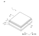
- FIG. 1 is a perspective view of the light emitting device according to the embodiment
- FIG. 2 is an exploded perspective view of the light emitting device shown in FIG. 1
- FIG. 3 (a) is a light emitting device taken along the line AA shown in FIG. 3 (b) is a perspective view of the microlens shown in FIG. 3 (a).
- the cross-sectional view shown in FIG. 3A is for explaining the structure of the light emitting device, and the scale of each component of the light emitting device is different from the scale of the actual component of the light emitting device. ..
- the light emitting device 1 has a cavity structure substrate 2, a VCSEL 3, a photodiode 4, and a microlens array 5.
- the cavity structure substrate 2 is formed of a mounting substrate 21 and a frame member 22, and has a recess 20 on which the VCSEL 3 and the photodiode 4 are mounted.
- the mounting substrate 21 is, for example, an aluminum nitride substrate, and a wiring pattern for supplying electric power to the VCSEL 3 and the photodiode 4 is arranged on the front surface, and an anode 23 and a cathode 24 for supplying electric power to the VCSEL 3 are arranged on the back surface.
- the frame member 22 is a frame-shaped member formed of a highly reflective member such as alumina and having through holes formed therein, and forms a recess 20 together with the mounting substrate 21.
- the VCSEL3 is also called a vertical cavity surface emitting laser (Vertical Cavity Surface Emitting Laser), and a plurality of emitters that emit laser light are arranged on the surface in an array at equal intervals.
- the VCSEL3 has, for example, 364 (26 ⁇ 14) emitters, and the 364 emitters are hexagonally arranged at a pitch of 0.0385 mm.
- the VCSEL 3 emits coherent laser light from the emitter toward the microlens array 5 according to the voltage applied between the anode 23 and the cathode 24.
- the divergence angle of the laser light emitted from the emitter is about 15 ° to 30 °, for example, 27 °.
- the VCSEL 3 is mounted on the cavity structure substrate 2 via the DB paste 6 containing the fine particle metal powder, and is electrically connected to the cathode 24. Further, the VCSEL 3 is electrically connected to the anode 23 via the bonding wire 7.
- the photodiode 4 receives the laser beam emitted by the VCSEL 3 and outputs a current corresponding to the received laser beam to a control device (not shown) arranged outside the light emitting device 1 via the photodiode electrode. ..
- the control device to which the current is input from the photodiode 4 controls the electric power supplied to the VCSEL 3 so as to make the light intensity of the laser light emitted from the VCSEL 3 a desired intensity.
- the microlens array 5 is a beam forming element such as a diffuser that beam forms the laser beam emitted by the VCSEL3.
- the microlens array 5 is fixed to the cavity structure substrate 2 by adhering the outer edge to the upper surface of the frame member 22 by the UV epoxy high-tixo-shaped adhesive 8.
- the area of the microlens array 5 when viewed in a plan view is smaller than the area of the outer edge of the frame member 22.
- the microlens array 5 can be adhered to the upper surface of the frame material 22 without the adhesive 8 flowing between the microlenses 51.
- the microlens array 5 By adhering the microlens array 5 to the frame material 22 using the high-tixo-shaped adhesive 8, it is not necessary to form an adhesive plane for arranging the adhesive on the outer edge of the microlens array 5. Since the microlens array 5 does not have to form an adhesive plane on the outer edge, it is easy to manufacture and the manufacturing cost can be suppressed.
- the area when the microlens array 5 is viewed in a plan view is smaller than the area of the outer edge of the frame member 22, when the stretching direction of the side of the microlens array 5 and the stretching direction of the side of the frame member 22 are deviated and bonded.
- the microlens array 5 protrudes from the outer edge of the frame member 22.
- Adhesion accuracy may be low, resulting in low manufacturing costs.
- the microlens array 5 can be arranged so as to cover the entire recess 20 even when the microlens array 5 is arranged at the time of bonding, and the lens position. The occurrence of optical loss due to misalignment or the like is suppressed.
- the microlens array 5 has a base material 50 and a plurality of microlenses 51 arranged so as to be aligned in the first direction and the second direction on the base material 50.
- the base material 50 has, for example, a rectangular planar shape formed of glass and formed by a pair of sides extending in the first direction and a pair of sides extending in the second direction orthogonal to the first direction.
- Each of the plurality of microlenses 51 is a convex lens formed of, for example, a thermoplastic resin such as a polyarylate resin, a thermosetting resin such as a silicone resin, and an ultraviolet curable resin such as an epoxy resin.
- the base material 50 and the plurality of microlenses 51 are formed as separate members, but in the microlens array according to the embodiment, the base material and the microlens may be integrally molded. ..
- the base material and the microlens may be integrally molded by injection molding a thermoplastic resin, a thermosetting resin, an ultraviolet curable resin, or the like.
- the microlens 51 may be formed as an aggregate of smaller lenses.
- each of the plurality of microlenses 51 is a plane surrounded by the ends of the curved surfaces 51b at which the curved surfaces 51b of the plurality of microlenses 51 start to stand, and each has a rectangular planar shape.
- each vertex T has a bottom surface 51a in the offset direction of any one of the first direction, the second direction, the third direction opposite to the first direction, and the fourth direction opposite to the second direction. Offset from the center point C of.
- the apex T of the microlens 51 is the portion farthest from the bottom surface 51a of the curved surface 51b of the microlens 51, and the center point C of the bottom surface 51a of the microlens 51 is the intersection of the diagonal lines of the bottom surface 51a.
- Each is divided into a microlens group 510 including a total of 16 microlenses in 4 rows ⁇ 4 columns having the same offset direction.
- reference patterns having different offset directions of the microlenses 51 included in the adjacent microlens group 510 are formed so as to repeatedly appear in the first direction and the second direction.
- the first pitch P1 which is the arrangement pitch of each of the plurality of microlenses 51 arranged in the first direction, is, for example, 0.075 mm, and is the second arrangement pitch of the plurality of microlenses 51 arranged in the second direction.
- the pitch P2 is, for example, 0.050 mm.
- FIG. 4A is a diagram showing a reference pattern 52 including 16 microlens groups 510.
- FIG. 4B is a plan view of the first microlens included in the reference pattern 52
- FIG. 4C is a plan view of the second microlens included in the reference pattern 52
- FIG. 4D is a plan view of the second microlens included in the reference pattern 52.
- FIG. 4 (e) is a plan view of the third microlens included in the reference pattern 52
- FIG. 4 (e) is a plan view of the fourth microlens included in the reference pattern 52.
- the reference pattern 52 has a first microlens group 511, a second microlens group 512, a third microlens group 513, and a fourth microlens group 514.
- Each of the first microlens group 511, the second microlens group 512, the third microlens group 513, and the fourth microlens group 514 includes a microlens group 510 containing a total of 16 microlenses 51 in 4 rows ⁇ 4 columns. Is.
- the apex T of the first microlens 511a included in the first microlens group 511 is offset in the first direction from the center point C of the bottom surface 51a, and the second microlens 512a included in the second microlens group 512 is of the bottom surface 51a.
- the vertex T is offset from the center point C in the second direction.
- the apex T of the third microlens 513a included in the third microlens group 513 is offset in the third direction from the center point C of the bottom surface 51a
- the fourth microlens 514a included in the fourth microlens group 514 is the bottom surface.
- the vertex T is offset from the center point C of 51a in the fourth direction.
- the microlens group 510 is a general term for the first microlens group 511, the second microlens group 512, the third microlens group 513, and the fourth microlens group 514.
- the microlens 51 is a general term for the first microlens 511a, the second microlens 512a, the third microlens 513a, and the fourth microlens 514a.
- the separation distance between the center point C and the apex T of the bottom surface 51a is the first offset distance O1
- the separation distance between the center point C and the apex T of the bottom surface 51a is the second offset distance O2
- the separation distance between the center point C and the apex T of the bottom surface 51a is the third offset distance O3
- the fourth microlens 514a the center point C and the apex T of the bottom surface 51a
- the separation distance between them is the fourth offset distance O4.
- the first offset distance O1 is the same as the third offset distance O3, and the second offset distance O2 is the same as the fourth offset distance O4.
- the first offset ratio R1 is indicated by the ratio of the first offset distance O1 to the first pitch P1, and in the second microlens group 512, the second offset ratio R2 is the second with respect to the second pitch P2. It is indicated by the ratio of 2 offset distances O2.
- the third offset ratio R3 is indicated by the ratio of the third offset distance O3 to the first pitch P1
- the fourth offset ratio R4 is the second with respect to the second pitch P2. It is indicated by the ratio of 4 offset distances O4.
- the first offset ratio R1 is the same as the second offset ratio R2, the third offset ratio R3, and the fourth offset ratio R4.
- the reference pattern 52 includes a total of 16 microlens groups 510 in four rows each in the first direction and the second direction.
- the fourth microlens group 514 is arranged adjacent to the first direction and the fourth direction of the first microlens group 511, and the second micron is arranged in the second direction and the third direction of the first microlens group 511.
- Lens groups 512 are arranged adjacent to each other.
- the offset directions of the microlenses 51 included in the second microlens group 512 and the fourth microlens group 514 adjacent to the first direction, the second direction, the third direction, and the fourth direction of the first microlens group 511 are the first. 1 It is orthogonal to the offset direction of the microlens 51 included in the microlens group 511.
- the first microlens group 511 is arranged adjacent to the first direction and the fourth direction of the second microlens group 512, and the third micro is arranged in the second direction and the third direction of the second microlens group 512.
- Lens groups 513 are arranged adjacent to each other.
- the offset directions of the microlenses 51 included in the first microlens group 511 and the third microlens group 513 adjacent to the first direction, the second direction, the third direction, and the fourth direction of the second microlens group 512 are the first. 2 It is orthogonal to the offset direction of the microlens 51 included in the microlens group 512.
- the second microlens group 512 is arranged adjacent to the first direction and the fourth direction of the third microlens group 513, and the fourth micro is arranged in the second direction and the third direction of the third microlens group 513.
- Lens groups 514 are arranged adjacent to each other.
- the offset directions of the microlenses 51 included in the second microlens group 512 and the fourth microlens group 514 adjacent to the first direction, the second direction, the third direction, and the fourth direction of the third microlens group 513 are the first. 3 It is orthogonal to the offset direction of the microlens 51 included in the microlens group 513.
- the third microlens group 513 is arranged adjacent to the first direction and the fourth direction of the fourth microlens group 514, and the first micron is arranged in the second direction and the third direction of the fourth microlens group 514.
- Lens groups 511 are arranged adjacent to each other.
- the offset directions of the microlenses 51 included in the first microlens group 511 and the third microlens group 513 adjacent to the first direction, the second direction, the third direction, and the fourth direction of the fourth microlens group 514 are the first. 4 It is orthogonal to the offset direction of the microlens 51 included in the microlens group 514.
- each of the first microlens group 511, the second microlens group 512, the third microlens group 513, and the fourth microlens group 514 is arranged in a row in the first direction.
- each of the first microlens group 511 to the fourth microlens group 514 is arranged in the first direction one by one in a row, it is per row of the first offset distance arranged in the first direction.
- the total value and the total value per row of the third offset distance are the same.
- the total value per row of the second offset distances arranged in the first direction and the total value per row of the fourth offset distances are the same.
- each of the first microlens group 511, the second microlens group 512, the third microlens group 513, and the fourth microlens group 514 is arranged in a row in the second direction.
- the total value of the distances per row of the first offset distances arranged in the second direction and the total value of the total values of the third offset distances per row are the same, and the second direction The total value per row of the second offset distances arranged in a row and the total value per row of the fourth offset distances are the same.
- FIG. 5A and 5B are views for explaining a preferable positional relationship between VCSEL3 and the microlens array 5
- FIG. 5A is a partial cross-sectional view of the light emitting device 1
- FIG. 5B is a microscopic view. It is a partial plan view of the lens array 5.
- the beam diameter ⁇ when the laser beam emitted from one point of the light source VCSEL3 reaches the apex is the vertical separation distance h between the surface of the VCSEL3 and the apex of the microlens 51, and the laser emitted by the VCSEL3. From the light divergence angle ⁇
- the first pitch PG1 which is the pitch in the first direction of the microlens group 510 with the beam diameter ⁇
- the second pitch PG2 which is the pitch in the second direction of the microlens group are 1.7 x PG1 ⁇ ⁇ ⁇ 16 x PG1 1.7 x PG2 ⁇ ⁇ ⁇ 16 x PG2 It is preferable to have a relationship with.
- FIG. 6 is a diagram showing the distribution of the beam light of VCSEL3 at the apex of the microlens 51 in the light emitting device 1.
- the broken line indicates the inner wall of the frame member 22.
- the separation distance between the VCSEL 3 and the apex of the microlens 51 is 0.4 mm.
- the beam diameter of the laser beam 515 emitted from the VCSEL 3 at the apex of the microlens 51 is 0.192 mm.
- the first pitch PG1 and the second pitch PG2 which are the pitches of the microlens group 510 in the first and second directions.
- FIG. 7 is a diagram showing an illuminance distribution calculated by simulation when the ratio of the first pitch PG1 and the second pitch PG2 is 4: 3.
- FIG. 7A shows an illuminance distribution when the beam diameter ⁇ is 1.04 times that of the first pitch PG1 and 1.39 times that of the second pitch PG2.
- FIG. 7B shows the illuminance distribution when the beam diameter ⁇ is 1.22 times that of the first pitch PG1 and 1.63 times that of the second pitch PG2.
- FIG. 7C shows the illuminance distribution when the beam diameter ⁇ is 1.40 times that of the first pitch PG1 and 1.89 times that of the second pitch PG2.
- FIG. 7A shows an illuminance distribution when the beam diameter ⁇ is 1.04 times that of the first pitch PG1 and 1.39 times that of the second pitch PG2.
- FIG. 7B shows the illuminance distribution when the beam diameter ⁇ is 1.22 times that of the first pitch PG1 and 1.63 times that of the second pitch PG2.
- FIGS. 7 (a) to 7 (f) shows the illuminance distribution when the beam diameter ⁇ is 1.92 times that of the first pitch PG1 and 2.56 times that of the second pitch PG2.
- the upper figure is a two-dimensional image showing the illuminance distribution of the laser beam emitted from the light emitting device 1
- the lower figure is a diagram showing the illuminance distribution in the first direction.
- FIG. 8 is a diagram showing an illuminance distribution calculated by simulation when the ratio of the first pitch PG1 and the second pitch PG2 is 1: 1.
- FIG. 8A shows the illuminance distribution when the beam diameter ⁇ is 1.04 times that of the first pitch PG1 and the second pitch PG2.
- FIG. 8B shows the illuminance distribution when the beam diameter ⁇ is 1.22 times that of the first pitch PG1 and the second pitch PG2.
- FIG. 8C shows the illuminance distribution when the beam diameter ⁇ is 1.40 times that of the first pitch PG1 and the second pitch PG2.
- FIG. 8D shows the illuminance distribution when the beam diameter ⁇ is 1.58 times that of the first pitch PG1 and the second pitch PG2.
- FIG. 8A shows the illuminance distribution when the beam diameter ⁇ is 1.04 times that of the first pitch PG1 and the second pitch PG2.
- FIG. 8B shows the illuminance distribution when the beam diameter ⁇ is 1.22 times that of the
- FIG. 8E shows the illuminance distribution when the beam diameter ⁇ is 1.74 times that of the first pitch PG1 and the second pitch PG2.
- FIG. 8 (f) shows the illuminance distribution when the beam diameter ⁇ is 1.92 times that of the first pitch PG1 and the second pitch PG2.
- the upper figure is a two-dimensional image showing the illuminance distribution of the laser beam emitted from the light emitting device 1
- the lower figure is a diagram showing the illuminance distribution in the first direction.
- the divergence angle of the laser beam emitted from VCSEL3 is about 15 ° to 30 °, and the minimum values of the first pitch PG1 and the second pitch PG2 that can be manufactured are about 20 ⁇ m.
- the separation distance h between the VCSEL 3 and the apex of the microlens 51 is about 0.2 mm to 0.6 mm.
- the minimum value of the separation distance h between the VCSEL 3 and the apex of the microlens 51, 0.2 mm, is a distance at which the microlens 51 does not come into contact with the bonding wire 7.
- the maximum value of the separation distance h between the VCSEL 3 and the apex of the microlens 51, 0.6 mm, is a distance determined from the viewpoint of miniaturization.
- the preferable value of the separation distance h between the VCSEL 3 and the apex of the microlens 51 is 0.4 mm.
- the beam diameter ⁇ is set to 0.6 mm, which is the maximum value of the separation distance h between the VCSEL 3 and the apex of the microlens 51, and 30 °, which is the maximum value of the divergence angle of the laser beam emitted from the VCSEL 3 (1). It is calculated by substituting into. 16 which is the maximum multiple of the first pitch PG1 and the second pitch PG2 of the beam diameter ⁇ is the beam diameter ⁇ calculated by the equation (1) at 20 ⁇ m which is the minimum value of the first pitch PG1 and the second pitch PG2. It is calculated by dividing.
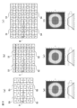
- FIG. 9 is a diagram showing a change in the illuminance distribution when the offset rate of the apex from the center point of the bottom surface of the microlens 51 is changed.
- FIG. 9A shows a case where the first offset rate R1 and the second offset rate R2 are zero
- FIG. 9B shows a case where the first offset rate R1 and the second offset rate R2 are the first pitch P1 and the second pitch. The case where it is 5% of P2 is shown.
- FIG. 9C shows a case where the first offset rate R1 and the second offset rate R2 are 10% of the first pitch P1 and the second pitch P2
- FIG. 9D shows the case where the first offset rate R1 and the second offset rate R2 are used.
- FIG. 9 (e) shows a case where the first offset rate R1 and the second offset rate R2 are 20% of the first pitch P1 and the second pitch P2, and FIG. 9 (f) shows the first offset rate R1 and the second.
- the case where the offset rate R2 is 25% of the first pitch P1 and the second pitch P2 is shown.
- 9 (a) to 9 (f) the above figure is a two-dimensional image showing the illuminance distribution of the image displayed on the screen which is the irradiation region where the laser beam emitted from the light emitting device 1 is irradiated.
- the figure below is a diagram showing the illuminance distribution in the first direction.
- the separation distance between the light emitting device 1 and the screen on which the image is displayed is 50 cm, and the screen on which the image is displayed has a square shape with a side length of 100 cm.
- the illuminance distribution of the image displayed on the screen changes from a substantially rectangular shape to a substantially elliptical shape. It transforms into.
- Table 1 shows the average irradiance of the region where the divergence angle is within the range of 60 ° in the first direction and the divergence angle is within the range of 45 ° in the second direction.
- the irradiance ratio indicates the ratio of irradiance according to the change in the offset rate when the offset rate of the apex from the center point in the first direction and the second direction is zero as 100%. ..
- the irradiance ratio is 90% when the offset rate is 20% or less of the first pitch P1 and the second pitch P2, and maintains a substantially rectangular shape. However, the irradiance ratio is less than 90% when the offset rate is 25% of the first pitch P1 and the second pitch P2, and changes from a substantially rectangular shape to a substantially elliptical shape. Therefore, the offset rate is preferably 20% or less of the first pitch P1 and the second pitch P2.
- FIG. 10 is a diagram showing a change in the distribution of interference fringes when the offset rate of the apex from the center point of the bottom surface of the microlens 51 is changed.
- FIG. 10A shows a case where the first offset rate R1 and the second offset rate R2 are zero
- FIG. 10B shows a case where the first offset rate R1 and the second offset rate R2 are the first pitch P1 and the second pitch. The case where it is 5% of P2 is shown.
- FIG. 10 (c) shows a case where the first offset rate R1 and the second offset rate R2 are 10% of the first pitch P1 and the second pitch P2
- FIG. 10 (d) shows the first offset rate R1 and the second.
- FIG. 10 (e) shows a case where the first offset rate R1 and the second offset rate R2 are 20% of the first pitch P1 and the second pitch P2, and FIG. 10 (f) shows the first offset rate R1 and the second.
- the case where the offset rate R2 is 25% of the first pitch P1 and the second pitch P2 is shown.
- the upper figure is a two-dimensional image showing the distribution of interference fringes of the image displayed on the screen by the laser beam emitted from the light emitting device 1, and the lower figure is the first direction. It is a figure which shows the intensity distribution of the interference fringe.
- the image displayed on the screen has interference fringes distributed with strong intensity over the entire surface.
- the offset rate is 5% or more of the first pitch P1 and the second pitch P2
- the intensity of the interference fringes is significantly reduced as compared with the case where the offset rate of the vertices is zero.
- the interference fringes gradually decrease as the offset ratio of the vertices increases.
- the offset rate of the microlens 51 when the offset rate of the microlens 51 is 5% or more, the interference fringes are significantly reduced, and when the offset rate of the microlens 51 is 20% or less, the irradiance ratio is 90% or more. .. Therefore, the offset rate of the microlens 51 is preferably 5% or more and 20% or less. Further, when the offset rate of the microlens 51 is 5% or more, the interference fringes are further reduced. Therefore, the offset rate of the microlens 51 is more preferably 15% or more and 20% or less.
- the microlens array 5 improves the uniformity of the intensity of the light applied to the irradiation region by arranging the microlenses 51 whose vertices are offset from the center point so that the reference patterns 52 appear repeatedly while being adjacent to each other. Can be done.
- the design depends on an uncertain element called random, and the result unintended by the designer is obtained. Since it may be obtained, it is necessary to repeat the optical simulation in order to obtain the result intended by the designer, which may increase the design load. That is, it is not easy to strictly control the arrangement of the vertices of the lens, and it is not easy to control the directivity of the lens in which the vertices are arranged at random.
- the microlens array 5 By arranging the microlens array 5 so that the reference patterns 52 appear repeatedly while being adjacent to each other, the directivity can be controlled with high accuracy and easily.
- the design cost may increase because the optical simulation is repeatedly executed to optimize the optical characteristics.
- the optical characteristics can be optimized by designing the reference pattern 52, so that the design cost can be suppressed as compared with the lens in which the vertices are randomly arranged.
- the microlens group 510 is arranged so that the directions in which the apex T is offset from the microlens group 510 adjacent to the first direction, the second direction, the third direction, and the fourth direction are orthogonal to each other. As a result, the uniformity of the intensity of the light applied to the irradiation region can be further improved.
- the first offset distance O1 between the center point C and the apex T in the first microlens group 511 is the first between the center point C and the apex T in the third microlens group 513. It is the same as the 3 offset O3 distance.
- the second offset distance O2 between the center point C and the apex T in the second microlens group 512 is the same as the fourth offset distance O4 between the center point C and the apex T in the fourth microlens group 514. Is.
- the first offset distance O1 and the third offset distance O3, which are offset in opposite directions, and the second offset distance O2 and the fourth offset distance O4 are made the same to enhance the regularity of the offset, thereby increasing the regularity of the offset.
- the uniformity of the intensity of the light irradiated to the can be further improved.
- first offset ratio R1 and the third offset ratio R3 in the first microlens group 511 and the third microlens group 513 are the second offset ratio R2 and the third offset ratio R2 in the second microlens group 512 and the fourth microlens group 514.
- the offset ratio is the same as R4.
- the microlens array 5 sets the first offset ratio R1 and the third offset ratio R3 and the second offset ratio R2 and the fourth offset ratio R4 to be the same to enhance the regularity of the offset, thereby increasing the intensity of the light applied to the irradiation region. Uniformity can be further improved.
- the microlens array 5 is a laser capable of suppressing interference fringes and irradiating an irradiation region with a uniform intensity by setting the first offset ratio R1 and the second offset ratio R2 to 5% or more and 20% or less. It can emit light.
- the total value per row of the first offset distance O1 is the same as the total value per row of the third offset distance O3, and the first The total value per row of the two offset distances O2 becomes the same as the total value per row of the fourth offset distance O4.
- the microlens array 5 sets the total value per row of the first offset distance O1 and the third offset distance O3 arranged in the first direction, and the total value per row of the second offset distance O2 and the fourth offset distance O4. By making them the same, the uniformity of the intensity of the light applied to the irradiation region can be further improved.
- the total value per row of the first offset distance O1 is the same as the total value per row of the third offset distance O3, and the third offset distance O3 is the same.
- the total value per row of the two offset distances O2 becomes the same as the total value per row of the fourth offset distance O4.
- the microlens array 5 sets the total value per row of the first offset distance O1 and the third offset distance O3 arranged in the second direction, and the total value per row of the second offset distance O2 and the fourth offset distance O4. By making them the same, the uniformity of the intensity of the light applied to the irradiation region can be further improved.
- the beam diameter when the laser beam reaches the microlens 51 is 1.7 times or more and 16 times or less the arrangement pitch in the first direction and the second direction of the microlens group 510. Therefore, the interference fringes are not unevenly distributed, and the irradiation region can be irradiated with a uniform intensity.
- FIGS. 1 to 10 (Modified example of the microlens array according to the embodiment) Although the light emitting device 1 and the microlens array 5 which are examples of the light emitting device and the microlens array according to the embodiment have been described with reference to FIGS. 1 to 10, the microlens array according to the embodiment is shown in FIGS. 1 to 10. It is not limited to the embodiments described with reference to it.
- the first offset distance O1 of the first microlens group 511 may be different from the third offset distance O3 of the third microlens group 513
- the second offset distance O2 of the second microlens group 512 may be the fourth micro. It may be different from the fourth offset distance 4 of the lens group 514.
- the plurality of microlenses 51 are convex lenses, in the microlens array according to the embodiment, the plurality of microlenses may be concave lenses.
- the reference pattern 52 includes a total of 16 microlens groups 510 in 4 rows and 4 columns, but in the microlens array according to the embodiment, the number of microlens groups included in the reference pattern is It is not limited to a total of 16 lenses in 4 rows and 4 columns.
- FIG. 11 is a diagram showing a reference pattern according to the first modification.
- the reference pattern 53 includes a total of nine microlens groups 510 in three rows each in the first direction and the second direction.
- the reference pattern 53 includes two first microlens groups 511, three second microlens groups 512, two third microlens groups 513, and two fourth microlens groups 514.
- each of the first microlens group 511 to the fourth microlens group 514 has a direction in which the apex is offset from the microlens group adjacent to the first direction, the second direction, the third direction, and the fourth direction. Arranged so as to be orthogonal.
- FIG. 12 is a diagram showing a reference pattern according to the second modification.
- the reference pattern 54 includes a total of 25 microlens groups 510 in 5 rows each in the first direction and the second direction.
- the reference pattern 54 includes six first microlens groups 511, seven second microlens groups 512, six third microlens groups 513, and six fourth microlens groups 514.
- each of the first microlens group 511 to the fourth microlens group 514 has a direction in which the apex is offset from the microlens group adjacent to the first direction, the second direction, the third direction, and the fourth direction. Arranged so as to be orthogonal.
- the same number of microlens groups 510 are arranged in the first direction and the second direction, but in the microlens array according to the embodiment, the microlens groups 510 arranged in the first direction.
- the number of may be different from the number of the microlens group 510 arranged in the second direction.
- FIG. 13 is a diagram showing the comparison results of the illuminance distributions of the reference pattern 52 according to the embodiment, the reference pattern 53 according to the first modification, and the reference pattern 54 according to the second modification.
- FIG. 13 (a) shows the arrangement of the reference pattern 53 including the microlens group 510 of 3 rows and 3 columns
- FIG. 13 (b) shows the arrangement of the reference pattern 52 including the micro lens group 510 of 4 rows and 4 columns.
- FIG. 13 (c) shows an array of reference patterns 54 including a 5 row 5 column microlens group 510.
- 13 (d) shows the illuminance distribution of the reference pattern 53
- FIG. 13 (e) shows the illuminance distribution of the reference pattern 52
- FIG. 13 (f) shows the illuminance distribution of the reference pattern 54.
- the microlens group 510 of the adjacent reference pattern 53 and the microlens group 510 having one side in contact with each other are arranged so that the offset directions are opposite to each other. And are not orthogonal to each other.
- the offset directions of the microlens group 510 of the adjacent reference pattern 53 and the microlens group 510 whose one side is in contact with each other are not orthogonal to each other, interference fringes are more likely to occur than the reference pattern 52.
- the offset directions of the microlens group 510 of the adjacent reference pattern 54 and the microlens group 510 having one side in contact with each other are oriented in the same direction or opposite to each other. They are arranged so that they face each other and are not orthogonal to each other. Since the reference pattern 54 includes a pattern in which the microlens group 510 of the adjacent reference pattern 54 and the microlens group 510 whose one side is in contact with each other are arranged so that the offset directions are in the same direction, interference fringes are further formed as compared with the reference pattern 53. It is easy to occur.
- the offset directions of the microlens group 510 included in the adjacent reference pattern 53 are all arranged so as to be orthogonal to each other, so that the reference pattern 53 and the reference pattern 53 and the reference pattern 53 are arranged so as to be orthogonal to each other. Interference fringes are less likely to occur than 54.
- the illuminance distribution of the reference pattern 52 including the even-numbered microlens group 510 has less distortion than the illuminance distribution of the reference pattern 53 and the reference pattern 54 including the odd-numbered microlens group 510, and the reference pattern is smaller than the odd-numbered row. It is preferable to include an even-numbered row of microlens groups 510.
- the number of microlens groups arranged in each of the first direction and the second direction is preferably an even number of 4 or more.
- the number of microlens groups arranged in each of the first direction and the second direction is more preferably 4 or 8.
- the reference pattern in which the number of microlens groups arranged in each of the first direction and the second direction is eight is formed by arranging four reference patterns 52.
- reference patterns in which the vertices of adjacent microlens groups 510 are offset in a predetermined direction are formed so as to repeatedly appear in the first direction and the second direction.
- reference patterns in which the vertices of adjacent microlenses 51 are offset in predetermined directions may be formed so as to repeatedly appear in the first direction and the second direction.
- FIG. 14A is a diagram showing a reference pattern according to the third modification
- FIG. 14B is a diagram showing an illuminance distribution calculated by simulating a microlens array having the reference pattern according to the third modification. Is.
- the reference pattern 55 according to the third modification includes a total of 16 microlenses 51 in four rows each in the first direction and the second direction.
- the reference pattern 55 includes two first microlens groups 511, three second microlens groups 512, two third microlens groups 513, and two fourth microlens groups 514.
- the reference pattern 55 similarly to the reference patterns 52 to 54, it is possible to irradiate the irradiation region with light having high intensity uniformity.
Landscapes
- Physics & Mathematics (AREA)
- Engineering & Computer Science (AREA)
- General Engineering & Computer Science (AREA)
- General Physics & Mathematics (AREA)
- Optics & Photonics (AREA)
- Condensed Matter Physics & Semiconductors (AREA)
- Electromagnetism (AREA)
- Semiconductor Lasers (AREA)
Abstract
マイクロレンズアレイは、第1方向及び第2方向に伸延する平行に配置された辺を有する矩形状の平面形状を有する基材と、基材に配置された複数のマイクロレンズとを有し、マイクロレンズの立体形状の底面は矩形状であり、マイクロレンズは基材に第1方向及び第2方向に整列して配置され、マイクロレンズのそれぞれの頂点は、当該単体レンズの底面を形成する矩形状の中心点より第1方向、第2方向、第1方向と逆方向の第3方向、及び、第2方向と逆方向の第4方向の何れか一方向に所定量だけオフセットして配置され、複数のマイクロレンズは、マイクロレンズを複数含む基準パターンが、第1方向及び第2方向に繰り返し出現するように形成されている。
Description
本開示は、マイクロレンズアレイ及び発光装置に関する。
TOF(Time Of Flight)カメラに搭載される発光装置に搭載するディフューザとして、マイクロレンズをアレイ状に配置したマイクロレンズアレイを使用する技術が知られている(例えば、特許文献1を参照)。マイクロレンズアレイは、ディフューザ以外にも、ホモジェナイザ等のビーム成形素子として使用される。
マイクロレンズアレイを有する発光装置は、マイクロレンズアレイによって光源から出射された光を成形及び均一化することで、所望の配光分布を有する光を出射することができる。しかしながら、VCSEL(Vertical Cavity Surface Emitting LASER)とも称される垂直共振器面発光レーザを光源とした発光装置において、マイクロレンズアレイを使用すると、発光装置が出射した光により照射される照射領域に干渉縞が発生することがある。
マイクロレンズアレイをビーム成形素子として使用する発光装置において、マイクロレンズの曲率及び頂点の位置をランダムに相違させることによって、照射される照射領域に干渉縞が発生することを防止する技術が知られている(例えば、特許文献2~4を参照)。
特許文献2~4を参照に記載される技術は、マイクロレンズの曲率及び頂点の位置を相違させることで干渉縞の発生を抑制することができるが、曲面及び頂点の位置が異なるマイクロレンズの成形加工は加工難易度が高く、製造コストが増加するおそれがある。
特許文献5には、干渉縞の発生を抑制するために、マイクロレンズの曲率を変化させることなく、マイクロレンズの頂点の位置をランダムに変位させる技術が記載されている。特許文献5に記載される技術は、マイクロレンズの曲率を変化させることなく頂点の位置をランダムに変位させるので、製造コストを増加させることなく干渉縞の発生を抑制することができる。
しかしながら、特許文献5に記載される技術では、マイクロレンズの頂点の位置をランダムに変位させるため、マイクロレンズの頂点が偏在して、照射される照射領域に干渉縞が偏在し、照射領域に照射される光強度の均一性が低下するおそれがある。
本開示は、照射領域に照射される光の強度の均一性を向上させるマイクロレンズアレイを提供することを目的とする。
本開示に係るマイクロレンズアレイは、第1方向に伸延する平行に配置された一対の辺、及び第1方向と直交する第2方向に伸延する平行に配置された一対の辺を有する矩形状の平面形状を有する基材と、基材に配置された複数のマイクロレンズと、を有し、複数のマイクロレンズのそれぞれの立体形状の底面は、矩形状であり、複数のマイクロレンズは、基材に第1方向及び第2方向に整列して配置され、複数のマイクロレンズのそれぞれの頂点は、底面の中心点より第1方向、第2方向、第1方向と逆方向の第3方向、及び、第2方向と逆方向の第4方向の何れか1つのオフセット方向に所定量だけオフセットして配置され、複数のマイクロレンズは、マイクロレンズを複数含む基準パターンが、第1方向及び第2方向に繰り返し出現するように形成されている。
さらに、本開示に係るマイクロレンズアレイでは、基準パターンにおいて、隣接するマイクロレンズは、オフセット方向が相違することが好ましい。
さらに、本開示に係るマイクロレンズアレイでは、基準パターンは、オフセット方向が同一である複数のマイクロレンズによりそれぞれが形成される複数のマイクロレンズ群を含み、隣接するマイクロレンズ群に含まれるマイクロレンズは、オフセット方向が相違することが好ましい。
さらに、本開示に係るマイクロレンズアレイでは、基準パターンにおいて、マイクロレンズ群のそれぞれは、第1方向、2方向、第3方向及び第4方向に隣接するマイクロレンズ群のオフセット方向とオフセット方向が直交するように配置されることが好ましい。
さらに、本開示に係るマイクロレンズアレイでは、中心点と第1方向にオフセットした頂点との間の第1オフセット距離は、中心点と第3方向にオフセットした頂点との間の第3オフセット距離と同一であり、中心点と第2方向にオフセットした頂点との間の第2オフセット距離は、中心点と第4方向にオフセットした頂点との間の第4オフセット距離と同一であることが好ましい。
さらに、本開示に係るマイクロレンズアレイでは、第1方向に配列されるマイクロレンズの配置ピッチである第1ピッチに対する第1オフセット距離の比率である第1オフセット比率は、第2方向に配列されるマイクロレンズの配置ピッチである第2ピッチに対する第2オフセット距離の比率である第2オフセット比率と同一であることが好ましい。
さらに、本開示に係るマイクロレンズアレイでは、第1オフセット比率及び第2オフセット比率は、5%以上であり且つ20%以下であることが好ましい。
さらに、本開示に係るマイクロレンズアレイでは、基準パターンにおいて、第1方向に配列されるマイクロレンズ群は、第1オフセット距離の一列当たりの合計値が第3オフセット距離の一列当たりの合計値と同一になり、且つ、第2オフセット距離の一列当たりの合計値が第4オフセット距離の一列当たりの合計値と同一になるように、配置されることが好ましい。
さらに、本開示に係るマイクロレンズアレイでは、基準パターンにおいて、第2方向に配列されるマイクロレンズ群は、第1オフセット距離の一列当たりの合計値が第3オフセット距離の一列当たりの合計値と同一になり、且つ、第2オフセット距離の一列当たりの合計値が第4オフセット距離の一列当たりの合計値と同一になるように、配置されることが好ましい。
さらに、本開示に係るマイクロレンズアレイでは、基準パターンは、少なくとも16個のマイクロレンズ群を含み、基準パターンにおいて、第1方向に配列されるマイクロレンズ群の数は4以上の偶数であり、且つ、第2方向に配列される一群のマイクロレンズ群の数は4以上の偶数であることが好ましい。
さらに、本開示に係るマイクロレンズアレイでは、基準パターンにおいて、第1方向及び第2方向のそれぞれに配列されるマイクロレンズ群の数は、4又は8であることが好ましい。
また、本開示に係る発光装置は、基板と、基板に配置され、格子状に配置されたエミッタからレーザ光を出射する複数の半導体レーザを有する光源と、光源の上方に配置されたマイクロレンズアレイと、を有し、マイクロレンズアレイは、第1方向に伸延する平行に配置された一対の辺、及び、第1方向と直交する第2方向に伸延する平行に配置された一対の辺を有する矩形状の平面形状を有する基材と、基材に配置された複数のマイクロレンズと、を有し、複数のマイクロレンズを形成する単体のマイクロレンズの立体形状の底面は、それぞれ矩形状であり、複数のマイクロレンズは、基材に第1方向及び第2方向に整列して配置され、複数のマイクロレンズを形成する単体のマイクロレンズのそれぞれの頂点は、当該単体レンズの底面を形成する矩形状の中心点より第1方向、第2方向、第1方向と逆方向の第3方向、及び、第2方向と逆方向の第4方向の何れか一方向に所定量だけオフセットして配置され、複数のマイクロレンズの内、隣接するマイクロレンズの頂点がそれぞれ所定方向にオフセットする基準パターンが、第1方向及び第2方向に繰り返し出現するように形成されている。
さらに、本開示に係る発光装置では、光源が出射するレーザ光が頂点に達するときのビーム径は、複数のマイクロレンズの第1方向及び第2方向の配置ピッチのそれぞれの1.7倍以上であり且つ16倍以下であることが好ましい。
本開示に係るマイクロレンズアレイは、照射領域に照射される光の強度の均一性を向上させることができる。
以下、図面を参照して、本開示に係るマイクロレンズアレイ及び発光装置について説明する。ただし、本開示の技術的範囲はそれらの実施の形態には限定されず、特許請求の範囲に記載された発明とその均等物に及ぶ点に留意されたい。
(実施形態に係るマイクロレンズアレイの概要)
実施形態に係るマイクロレンズアレイは、所定の基準パターンが隣接しながら繰り返し出現するように、底面の中心点から頂点がオフセットしたマイクロレンズを配置することで、干渉縞の偏在を是正し、照射領域に照射される光の強度の均一性を向上させる。
実施形態に係るマイクロレンズアレイは、所定の基準パターンが隣接しながら繰り返し出現するように、底面の中心点から頂点がオフセットしたマイクロレンズを配置することで、干渉縞の偏在を是正し、照射領域に照射される光の強度の均一性を向上させる。
(実施形態に係る発光装置の構成および機能)
図1は実施形態に係る発光装置の斜視図であり、図2は、図1に示す発光装置の分解斜視図であり、図3(a)は図1に示すA-A線に沿う発光装置の断面図であり、図3(b)は図3(a)に示すマイクロレンズの斜視図である。なお、図3(a)に示す断面図は、発光装置の構造を説明するためのものであり、発光装置のそれぞれの構成要素の縮尺は、実際の発光装置の構成要素の縮尺とは相違する。
図1は実施形態に係る発光装置の斜視図であり、図2は、図1に示す発光装置の分解斜視図であり、図3(a)は図1に示すA-A線に沿う発光装置の断面図であり、図3(b)は図3(a)に示すマイクロレンズの斜視図である。なお、図3(a)に示す断面図は、発光装置の構造を説明するためのものであり、発光装置のそれぞれの構成要素の縮尺は、実際の発光装置の構成要素の縮尺とは相違する。
発光装置1は、キャビティ構造基板2と、VCSEL3と、フォトダイオード4と、マイクロレンズアレイ5とを有する。キャビティ構造基板2は、実装基板21及び枠材22によって形成され、VCSEL3及びフォトダイオード4が実装される凹部20を有する。実装基板21は、例えば窒化アルミニウム基板であり、VCSEL3及びフォトダイオード4に電力を供給する配線パターンが表面に配置されると共に、VCSEL3に電力を供給するアノード23及びカソード24が裏面に配置される。枠材22は、例えばアルミナ等の高反射性部材により形成され、貫通孔が形成された枠状の部材であり、実装基板21と共に凹部20を形成する。
VCSEL3は、垂直共振器面発光レーザ(Vertical Cavity Surface Emitting Laser)とも称され、レーザ光を出射する複数のエミッタが表面に等間隔にアレイ状に配置される。VCSEL3は、例えば364(26×14)個のエミッタを有し、364個のエミッタは、0.0385mmのピッチで六方配列される。
VCSEL3は、アノード23とカソード24との間に印加される電圧に応じて、コヒーレントなレーザ光をエミッタからマイクロレンズアレイ5に向けて出射する。エミッタから出射されるレーザ光の発散角は、15°~30°程度であり、例えば27度である。VCSEL3は、微粒子金属粉末を含有するDBペースト6を介してキャビティ構造基板2に実装され、カソード24に電気的に接続される。また、VCSEL3は、ボンディングワイヤ7を介してアノード23に電気的に接続される。
フォトダイオード4は、VCSEL3が出射したレーザ光を受光して、受光したレーザ光に応じた電流を、フォトダイオード用電極を介して発光装置1の外部に配置される不図示の制御装置に出力する。フォトダイオード4から電流が入力された制御装置は、VCSEL3が出射するレーザ光の光強度を所望の強度にするようにVCSEL3に供給する電力を制御する。
マイクロレンズアレイ5は、VCSEL3が出射したレーザ光をビーム成形するディフューザ等のビーム成形素子である。マイクロレンズアレイ5は、UVエポキシ高チクソ形の接着剤8によって外縁が枠材22の上面に接着されることで、キャビティ構造基板2に固定される。マイクロレンズアレイ5を平面視したときの面積は、枠材22の外縁の面積よりも小さい。
高チクソ形の接着剤8は、毛細管現象の発生が抑制されるので、接着剤8がマイクロレンズ51の間に流れ込むことなくマイクロレンズアレイ5を枠材22の上面に接着できる。高チクソ形の接着剤8を使用してマイクロレンズアレイ5を枠材22に接着することで、マイクロレンズアレイ5の外縁に接着剤を配置するための接着用平面を形成しなくてもよい。マイクロレンズアレイ5は、接着用平面を外縁に形成しなくてよいので、製造が容易であり、且つ、製造コストが抑制可能である。
マイクロレンズアレイ5を平面視したときの面積は、枠材22の外縁の面積よりも小さいので、マイクロレンズアレイ5の辺の延伸方向と枠材22の辺の延伸方向がずれて接着された場合でも、マイクロレンズアレイ5が枠材22の外縁から突出するおそれが低い。マイクロレンズアレイ5の辺の延伸方向が枠材22の辺の延伸方向からずれてもマイクロレンズアレイ5が枠材22の外縁から突出するおそれが低いので、マイクロレンズアレイ5の枠材22への接着精度は低くてもよく、製造コストが低くなる。また、マイクロレンズアレイ5は外縁まで複数のマイクロレンズ51が配置されるので、接着するときにマイクロレンズアレイ5の配置した場合でもの凹部20の全体を覆うように配置可能であり、レンズの位置ずれ等による光学ロスの発生が抑制される。
マイクロレンズアレイ5は、基材50と、基材50に第1方向及び第2方向に整列して配置される複数のマイクロレンズ51とを有する。基材50は、例えばガラスで形成され、第1方向に延伸する一対の辺、及び第1方向に直交する第2方向に延伸する一対の辺により形成された矩形の平面形状を有する。
複数のマイクロレンズ51のそれぞれは、例えばポリアリレート樹脂等の熱可塑性樹脂、シリコーン樹脂等の熱硬化性樹脂、及びエポキシ樹脂等の紫外線硬化樹脂で形成された凸レンズである。なお、マイクロレンズアレイ5では、基材50と複数のマイクロレンズ51とは別個の部材として形成されるが、実施形態に係るマイクロレンズアレイでは、基材とマイクロレンズとは一体成形されてもよい。例えば、実施形態に係るマイクロレンズアレイでは、基材とマイクロレンズとは、熱可塑性樹脂、熱硬化性樹脂及紫外線硬化樹脂等を射出成形することによって一体成形されてもよい。マイクロレンズ51は、さらに小さなレンズの集合体として形成されてもよい。
複数のマイクロレンズ51のそれぞれの底面51aは、複数のマイクロレンズ51のそれぞれの曲面51bが起立を開始する曲面51bの端部により囲まれた平面であり、それぞれが矩形状の平面形状を有する。マイクロレンズ51では、それぞれの頂点Tは、第1方向、第2方向、第1方向の反対の第3方向、及び第2方向の反対の第4方向の何れか一方のオフセット方向に、底面51aの中心点Cよりオフセットする。マイクロレンズ51の頂点Tはマイクロレンズ51の曲面51bの底面51aから最も離隔した部分であり、マイクロレンズ51の底面51aの中心点Cは底面51aの対角線の交点であり、複数のマイクロレンズ51のそれぞれは、オフセット方向が同一である4行×4列の合計16個のマイクロレンズを含むマイクロレンズ群510に区分される。複数のマイクロレンズ51では、隣接するマイクロレンズ群510に含まれるマイクロレンズ51のオフセット方向が相違する基準パターンが、第1方向及び第2方向に繰り返し出現するように形成されている。
第1方向に配列される複数のマイクロレンズ51のそれぞれの配置ピッチである第1ピッチP1は例えば0.075mmであり、第2方向に配列される複数のマイクロレンズ51の配置ピッチである第2ピッチP2は例えば0.050mmである。また、第1方向に配列されるマイクロレンズ51の数は、例えば256(=16×16)個である。
図4(a)は、16個のマイクロレンズ群510が含まれる基準パターン52を示す図である。図4(b)は基準パターン52に含まれる第1マイクロレンズの平面図であり、図4(c)は基準パターン52に含まれる第2マイクロレンズの平面図であり、図4(d)は基準パターン52に含まれる第3マイクロレンズの平面図であり、図4(e)は基準パターン52に含まれる第4マイクロレンズの平面図である。
基準パターン52は、第1マイクロレンズ群511と、第2マイクロレンズ群512と、第3マイクロレンズ群513と、第4マイクロレンズ群514とを有する。第1マイクロレンズ群511、第2マイクロレンズ群512、第3マイクロレンズ群513及び第4マイクロレンズ群514のそれぞれは、4行×4列の合計16個のマイクロレンズ51を含むマイクロレンズ群510である。第1マイクロレンズ群511に含まれる第1マイクロレンズ511aは底面51aの中心点Cから第1方向に頂点Tがオフセットし、第2マイクロレンズ群512に含まれる第2マイクロレンズ512aは底面51aの中心点Cから第2方向に頂点Tがオフセットする。また、第3マイクロレンズ群513に含まれる第3マイクロレンズ513aは底面51aの中心点Cから第3方向に頂点Tがオフセットし、第4マイクロレンズ群514に含まれる第4マイクロレンズ514aは底面51aの中心点Cから第4方向に頂点Tがオフセットする。なお、マイクロレンズ群510は、第1マイクロレンズ群511、第2マイクロレンズ群512、第3マイクロレンズ群513及び第4マイクロレンズ群514の総称である。また、マイクロレンズ51は、第1マイクロレンズ511a、第2マイクロレンズ512a、第3マイクロレンズ513a及び第4マイクロレンズ514aの総称である。
第1マイクロレンズ511aにおいて、底面51aの中心点Cと頂点Tとの間の離隔距離は、第1オフセット距離O1であり、第2マイクロレンズ512aにおいて、底面51aの中心点Cと頂点Tとの間の離隔距離は、第2オフセット距離O2である。第3マイクロレンズ513aにおいて、底面51aの中心点Cと頂点Tとの間の離隔距離は、第3オフセット距離O3であり、第4マイクロレンズ514aにおいて、底面51aの中心点Cと頂点Tとの間の離隔距離は、第4オフセット距離O4である。第1オフセット距離O1は第3オフセット距離O3と同一であり、第2オフセット距離O2は第4オフセット距離O4と同一である。
第1マイクロレンズ群511において、第1オフセット比率R1は第1ピッチP1に対する第1オフセット距離O1の比率で示され、第2マイクロレンズ群512において、第2オフセット比率R2は第2ピッチP2に対する第2オフセット距離O2の比率で示される。第3マイクロレンズ群513において、第3オフセット比率R3は第1ピッチP1に対する第3オフセット距離O3の比率で示され、第4マイクロレンズ群514において、第4オフセット比率R4は第2ピッチP2に対する第4オフセット距離O4の比率で示される。第1オフセット比率R1は、第2オフセット比率R2、第3オフセット比率R3及び第4オフセット比率R4と同一である。
基準パターン52は、第1方向及び第2方向に4列ずつ計16個のマイクロレンズ群510を含む。基準パターン52の第1方向の長さは0.30mm(=0.075mm×4)であり、基準パターン52の第2方向の長さは0.20mm(=0.050mm×4)である。
第1マイクロレンズ群511の第1方向及び第4方向には、第4マイクロレンズ群514が隣接して配置され、第1マイクロレンズ群511の第2方向及び第3方向には、第2マイクロレンズ群512が隣接して配置される。第1マイクロレンズ群511の第1方向、第2方向、第3方向及び第4方向に隣接する第2マイクロレンズ群512及び第4マイクロレンズ群514に含まれるマイクロレンズ51のオフセット方向は、第1マイクロレンズ群511に含まれるマイクロレンズ51のオフセット方向と直交する。
第2マイクロレンズ群512の第1方向及び第4方向には、第1マイクロレンズ群511が隣接して配置され、第2マイクロレンズ群512の第2方向及び第3方向には、第3マイクロレンズ群513が隣接して配置される。第2マイクロレンズ群512の第1方向、第2方向、第3方向及び第4方向に隣接する第1マイクロレンズ群511及び第3マイクロレンズ群513に含まれるマイクロレンズ51のオフセット方向は、第2マイクロレンズ群512に含まれるマイクロレンズ51のオフセット向と直交する。
第3マイクロレンズ群513の第1方向及び第4方向には、第2マイクロレンズ群512が隣接して配置され、第3マイクロレンズ群513の第2方向及び第3方向には、第4マイクロレンズ群514が隣接して配置される。第3マイクロレンズ群513の第1方向、第2方向、第3方向及び第4方向に隣接する第2マイクロレンズ群512及び第4マイクロレンズ群514に含まれるマイクロレンズ51のオフセット方向は、第3マイクロレンズ群513に含まれるマイクロレンズ51のオフセット方向と直交する。
第4マイクロレンズ群514の第1方向及び第4方向には、第3マイクロレンズ群513が隣接して配置され、第4マイクロレンズ群514の第2方向及び第3方向には、第1マイクロレンズ群511が隣接して配置される。第4マイクロレンズ群514の第1方向、第2方向、第3方向及び第4方向に隣接する第1マイクロレンズ群511及び第3マイクロレンズ群513に含まれるマイクロレンズ51のオフセット方向は、第4マイクロレンズ群514に含まれるマイクロレンズ51のオフセット方向と直交する。
また、基準パターン52では、第1マイクロレンズ群511、第2マイクロレンズ群512、第3マイクロレンズ群513及び第4マイクロレンズ群514のそれぞれが一列に1つずつ第1方向に配列される。基準パターン52では、第1マイクロレンズ群511~第4マイクロレンズ群514のそれぞれが一列に1つずつ第1方向に配列されるので、第1方向に配列される第1オフセット距離の一列当たりの合計値と第3オフセット距離の一列当たりの合計値とが同一になる。さらに、基準パターン52では、第1方向に配列される第2オフセット距離の一列当たりの合計値と第4オフセット距離の一列当たりの合計値とが同一になる。
また、基準パターン52では、第1マイクロレンズ群511、第2マイクロレンズ群512、第3マイクロレンズ群513及び第4マイクロレンズ群514のそれぞれが一列に1つずつ第2方向に配列される。基準パターン52では、第1方向と同様に、第2方向に配列される第1オフセット一列当たりの距離の合計値と第3オフセット距離の一列当たりの合計値とが同一になると共に、第2方向に一列に配列される第2オフセット距離の一列当たりの合計値と第4オフセット距離の一列当たりの合計値とが同一になる。
図5は、VCSEL3とマイクロレンズアレイ5との間の好適な位置関係を説明するための図であり、図5(a)は発光装置1の部分断面図であり、図5(b)はマイクロレンズアレイ5の部分平面図である。
光源であるVCSEL3の1点から出射されたレーザ光が頂点に達するときのビーム径Φは、VCSEL3の表面とマイクロレンズ51の頂点との間の鉛直方向の離隔距離h、及びVCSEL3が出射するレーザ光の発散角θから

により示される。ビーム径Φとのマイクロレンズ群510の第1方向のピッチである第1ピッチPG1及びのマイクロレンズ群の第2方向のピッチである第2ピッチPG2とは、
1.7×PG1≦Φ≦16×PG1
1.7×PG2≦Φ≦16×PG2
との関係を有することが好ましい。
1.7×PG1≦Φ≦16×PG1
1.7×PG2≦Φ≦16×PG2
との関係を有することが好ましい。
図6は、発光装置1においてマイクロレンズ51の頂点におけるVCSEL3のビーム光の分布を示す図である。図6において、破線は、枠材22の内壁を示す。
図6に示す例では、VCSEL3とマイクロレンズ51の頂点との間の離隔距離は、0.4mmである。マイクロレンズ51の頂点におけるVCSEL3から出射されるレーザ光515のビーム径は0.192mmである。また、基準パターン52のタイリング数は16(=4×4)個であり、タイリングされる領域の面積は0.96(=1.2mm×0.8mm)mm2である。
図7及び8を参照して、レーザ光が頂点に達するときのビーム径Φの最小値と第1方向及び第2方向のマイクロレンズ群510のピッチである第1ピッチPG1及び第2ピッチPG2との関係を説明する。
図7は、第1ピッチPG1及び第2ピッチPG2との比率が4:3の場合のシミュレーションにより演算された照度分布を示す図である。図7(a)は、ビーム径Φが第1ピッチPG1の1.04倍であり且つ第2ピッチPG2の1.39倍である場合の照度分布を示す。図7(b)は、ビーム径Φが第1ピッチPG1の1.22倍であり且つ第2ピッチPG2の1.63倍である場合の照度分布を示す。図7(c)は、ビーム径Φが第1ピッチPG1の1.40倍であり且つ第2ピッチPG2の1.89倍である場合の照度分布を示す。図7(d)は、ビーム径Φが第1ピッチPG1の1.58倍であり且つ第2ピッチPG2の2.11倍である場合の照度分布を示す。図7(e)は、ビーム径Φが第1ピッチPG1の1.74倍であり且つ第2ピッチPG2の2.32倍である場合の照度分布を示す。図7(f)は、ビーム径Φが第1ピッチPG1の1.92倍であり且つ第2ピッチPG2の2.56倍である場合の照度分布を示す。図7(a)~7(f)において、上図は発光装置1から出射されるレーザ光の照度分布を示す2次元画像であり、下図は第1方向の照度分布を示す図である。
図7(a)~7(d)に示されるように、ビーム径Φが第1ピッチPG1の1.7倍未満では、照度分布が矩形にならない。一方、図7(e)~7(f)に示されるように、ビーム径Φが第1ピッチPG1の1.7倍以上では、照度分布が矩形になる。発光装置1は、TOFセンサの光源として使用される場合、照度分布が矩形になることが好ましい。
図8は、第1ピッチPG1及び第2ピッチPG2との比率が1:1の場合のシミュレーションにより演算された照度分布を示す図である。図8(a)は、ビーム径Φが第1ピッチPG1及び第2ピッチPG2の1.04倍である場合の照度分布を示す。図8(b)は、ビーム径Φが第1ピッチPG1及び第2ピッチPG2の1.22倍である場合の照度分布を示す。図8(c)は、ビーム径Φが第1ピッチPG1及び第2ピッチPG2の1.40倍である場合の照度分布を示す。図8(d)は、ビーム径Φが第1ピッチPG1及び第2ピッチPG2の1.58倍である場合の照度分布を示す。図8(e)は、ビーム径Φが第1ピッチPG1及び第2ピッチPG2の1.74倍である場合の照度分布を示す。図8(f)は、ビーム径Φが第1ピッチPG1及び第2ピッチPG2の1.92倍である場合の照度分布を示す。図8(a)~8(f)において、上図は発光装置1から出射されるレーザ光の照度分布を示す2次元画像であり、下図は第1方向の照度分布を示す図である。
図8(a)~8(d)に示されるように、ビーム径Φが第1ピッチPG1及び第2ピッチPG2の1.7倍未満では、照度分布が矩形にならない。一方、図8(e)~8(f)に示されるように、ビーム径Φが第1ピッチPG1及び第2ピッチPG2の1.7倍以上では、照度分布が矩形になる。
VCSEL3から出射されるレーザ光の発散角は15°~30°程度であり、製造可能な第1ピッチPG1及び第2ピッチPG2の最小値は20μm程度である。また、VCSEL3とマイクロレンズ51の頂点との間の離隔距離hは、0.2mm~0.6mm程度である。VCSEL3とマイクロレンズ51の頂点との間の離隔距離hの最小値である0.2mmは、マイクロレンズ51がボンディングワイヤ7に接触しない距離である。VCSEL3とマイクロレンズ51の頂点との間の離隔距離hの最大値である0.6mmは、小型化の観点から決定される距離である。なお、VCSEL3とマイクロレンズ51の頂点との間の離隔距離hの好適値は、0.4mmである。
ビーム径Φは、VCSEL3とマイクロレンズ51の頂点との間の離隔距離hの最大値である0.6mm、VCSEL3から出射されるレーザ光の発散角の最大値である30°を式(1)に代入することにより演算される。ビーム径Φの第1ピッチPG1及び第2ピッチPG2の最大倍数である16は、式(1)により演算されたビーム径Φを、第1ピッチPG1及び第2ピッチPG2の最小値である20μmで除することにより演算される。
図9及び10を参照して、マイクロレンズ51の中心点から第1方向に頂点がオフセットするオフセット率の好適な範囲について説明する。
図9は、マイクロレンズ51の底面の中心点からの頂点のオフセット率を変化させたときの照度分布の変化を示す図である。図9(a)は第1オフセット率R1及び第2オフセット率R2がゼロの場合を示し、図9(b)は第1オフセット率R1及び第2オフセット率R2が第1ピッチP1及び第2ピッチP2の5%である場合を示す。図9(c)は第1オフセット率R1及び第2オフセット率R2が第1ピッチP1及び第2ピッチP2の10%である場合を示し、図9(d)は第1オフセット率R1及び第2オフセット率R2が第1ピッチP1及び第2ピッチP2の15%である場合を示す。図9(e)は第1オフセット率R1及び第2オフセット率R2が第1ピッチP1及び第2ピッチP2の20%である場合を示し、図9(f)は第1オフセット率R1及び第2オフセット率R2が第1ピッチP1及び第2ピッチP2の25%である場合を示す。図9(a)~9(f)において、上図は発光装置1から出射されるレーザ光が照射される照射領域であるスクリーン上に表示される画像の照度分布を示す2次元画像であり、下図は第1方向の照度分布を示す図である。
図9に示す照度分布は、発光装置1と、画像が表示されるスクリーンとの間の離隔距離は50cmであり、画像が表示されるスクリーンは、一辺の長さが100cmの正方形状を有する。
第1方向及び第2方向への中心点からの頂点のオフセット率がゼロから増加するに従って、スクリーンに表示される画像の照度分布は、略矩形の形状から角が丸くなり、略楕円形の形状に変形していく。
表1は、発散角が第1方向の60°の範囲内であり且つ第2方向が45°の範囲内である領域の平均照射照度を示す。表1において、放射照度比は、第1方向及び第2方向への中心点からの頂点のオフセット率がゼロのときを100%としたときのオフセット率の変化に応じた放射照度の比率を示す。

放射照度比は、オフセット率が第1ピッチP1及び第2ピッチP2の20%以下であるとき、90%となり略矩形の形状を維持している。しかしながら、放射照度比は、オフセット率が第1ピッチP1及び第2ピッチP2の25%であるとき、90%未満となり略矩形の形状から略楕円の形状に変化している。したがって、オフセット率は、第1ピッチP1及び第2ピッチP2の20%以下であることが好ましい。
図10は、マイクロレンズ51の底面の中心点からの頂点のオフセット率を変化させたときの干渉縞の分布の変化を示す図である。図10(a)は第1オフセット率R1及び第2オフセット率R2がゼロの場合を示し、図10(b)は第1オフセット率R1及び第2オフセット率R2が第1ピッチP1及び第2ピッチP2の5%である場合を示す。図10(c)は第1オフセット率R1及び第2オフセット率R2が第1ピッチP1及び第2ピッチP2の10%である場合を示し、図10(d)は第1オフセット率R1及び第2オフセット率R2が第1ピッチP1及び第2ピッチP2の15%である場合を示す。図10(e)は第1オフセット率R1及び第2オフセット率R2が第1ピッチP1及び第2ピッチP2の20%である場合を示し、図10(f)は第1オフセット率R1及び第2オフセット率R2が第1ピッチP1及び第2ピッチP2の25%である場合を示す。図10(a)~10(f)において、上図は発光装置1から出射されるレーザ光によりスクリーンに表示される画像の干渉縞の分布を示す2次元画像であり、下図は第1方向の干渉縞の強度分布を示す図である。
第1方向及び第2方向への中心点からの頂点のオフセット率がゼロであるとき、スクリーンに表示される画像は、干渉縞が全面に亘って強い強度で分布している。一方、オフセット率が第1ピッチP1及び第2ピッチP2の5%以上であるとき、頂点のオフセット率がゼロであるときよりも干渉縞の強度が大幅に減少している。頂点のオフセット率が増加するに従って、干渉縞は徐々に減少している。
発光装置1では、マイクロレンズ51のオフセット率が5%以上であるとき、干渉縞は大幅に減少し、マイクロレンズ51のオフセット率が20%以下であるとき、放射照度比は90%以上となる。したがって、マイクロレンズ51のオフセット率は、5%以上20%以下であることが好ましい。さらに、マイクロレンズ51のオフセット率が5%以上であるとき、干渉縞は更に減少するので、マイクロレンズ51のオフセット率は、15%以上20%以下であることが更に好ましい。
(実施形態に係るマイクロレンズアレイの作用効果)
マイクロレンズアレイ5は、基準パターン52が隣接しながら繰り返し出現するように中心点から頂点がオフセットしたマイクロレンズ51を配置することで、照射領域に照射される光の強度の均一性を向上させることができる。
マイクロレンズアレイ5は、基準パターン52が隣接しながら繰り返し出現するように中心点から頂点がオフセットしたマイクロレンズ51を配置することで、照射領域に照射される光の強度の均一性を向上させることができる。
引用文献3等に記載される電子計算機により生成される乱数等によりレンズの頂点をランダムに配置する技術では、ランダムという不確定な要素に設計を依存することになり、設計者の意図しない結果が得られる場合があるから、設計者の意図した結果を得るためには、光学シミュレーションを繰り返す必要があり、設計負荷が膨大なものとなる恐れがある。つまり、レンズの頂点の配置を厳密に制御することは容易ではなく、ランダムに頂点を配置するレンズの指向性の制御は容易ではない。マイクロレンズアレイ5は、基準パターン52が隣接しながら繰り返し出現するように配置することで、指向性を高精度且つ簡便に制御できる。さらに、ランダムに頂点を配置するレンズでは、光学シミュレーションを繰り返し実行して光学特性を最適化するために、設計コストが上昇するおそれがある。一方、マイクロレンズアレイ5では、基準パターン52の設計により光学特性の最適化が図れるため、ランダムに頂点を配置するレンズよりも設計コストを抑制できる。
また、基準パターン52において、マイクロレンズ群510は、第1方向、第2方向、第3方向及び第4方向に隣接するマイクロレンズ群510と頂点Tがオフセットする方向が直交するように配置されることで、照射領域に照射される光の強度の均一性を更に向上できる。
また、マイクロレンズアレイ5では、第1マイクロレンズ群511における中心点Cと頂点Tとの間の第1オフセット距離O1は、第3マイクロレンズ群513における中心点Cと頂点Tとの間の第3オフセットO3距離と同一である。さらに、第2マイクロレンズ群512における中心点Cと頂点Tとの間の第2オフセット距離O2は、第4マイクロレンズ群514における中心点Cと頂点Tとの間の第4オフセット距離O4と同一である。マイクロレンズアレイ5は、反対方向にオフセットする第1オフセット距離O1と第3オフセット距離O3、及び第2オフセット距離O2と第4オフセット距離O4を同一にしてオフセットの規則性を高めることで、照射領域に照射される光の強度の均一性を更に向上できる。
また、第1マイクロレンズ群511及び第3マイクロレンズ群513における第1オフセット比率R1及び第3オフセット比率R3は、第2マイクロレンズ群512及び第4マイクロレンズ群514における第2オフセット比率R2及び第4オフセット比率R4と同一である。マイクロレンズアレイ5は、第1オフセット比率R1及び第3オフセット比率R3と第2オフセット比率R2及び第4オフセット比率R4を同一としてオフセットの規則性を高めることで、照射領域に照射される光の強度の均一性を更に向上できる。
さらに、マイクロレンズアレイ5は、第1オフセット比率R1及び第2オフセット比率R2を5%以上であり且つ20%以下とすることで、干渉縞が抑制され照射領域に均一な強度を照射可能なレーザ光を出射することができる。
さらに、基準パターン52において、第1方向に配列されるマイクロレンズ51は、第1オフセット距離O1の一列当たりの合計値が第3オフセット距離O3の一列当たりの合計値と同一になり、且つ、第2オフセット距離O2の一列当たりの合計値が第4オフセット距離O4の一列当たりの合計値と同一になる。マイクロレンズアレイ5は、第1方向に配列される第1オフセット距離O1及び第3オフセット距離O3の一列当たりの合計値、及び第2オフセット距離O2及び第4オフセット距離O4の一列当たりの合計値を同一とすることで、照射領域に照射される光の強度の均一性を更に向上できる。
さらに、基準パターン52において、第2方向に配列されるマイクロレンズ51は、第1オフセット距離O1の一列当たりの合計値が第3オフセット距離O3の一列当たりの合計値と同一になり、且つ、第2オフセット距離O2の一列当たりの合計値が第4オフセット距離O4の一列当たりの合計値と同一になる。マイクロレンズアレイ5は、第2方向に配列される第1オフセット距離O1及び第3オフセット距離O3の一列当たりの合計値、及び第2オフセット距離O2及び第4オフセット距離O4の一列当たりの合計値を同一とすることで、照射領域に照射される光の強度の均一性を更に向上できる。
また、発光装置1は、レーザ光がマイクロレンズ51に達するときのビーム径は、マイクロレンズ群510の第1方向及び第2方向の配置ピッチの1.7倍以上であり且つ16倍以下であるので、干渉縞が偏在せず、照射領域に均一な強度を照射できる。
(実施形態に係るマイクロレンズアレイの変形例)
図1~10を参照して実施形態に係る発光装置及びマイクロレンズアレイの一例である発光装置1及びマイクロレンズアレイ5が説明されたが、実施形態に係るマイクロレンズアレイは、図1~10を参照して説明された実施形態に限定されるものではない。
図1~10を参照して実施形態に係る発光装置及びマイクロレンズアレイの一例である発光装置1及びマイクロレンズアレイ5が説明されたが、実施形態に係るマイクロレンズアレイは、図1~10を参照して説明された実施形態に限定されるものではない。
例えば、第1マイクロレンズ群511の第1オフセット距離O1は第3マイクロレンズ群513の第3オフセット距離O3と相違してもよく、第2マイクロレンズ群512の第2オフセット距離O2は第4マイクロレンズ群514の第4オフセット距離4と相違してもよい。
また、複数のマイクロレンズ51は、凸レンズであるが、実施形態に係るマイクロレンズアレイでは、複数のマイクロレンズは、凹レンズであってもよい。
また、マイクロレンズアレイ5では、基準パターン52は、4行4列の合計16個のマイクロレンズ群510を含むが、実施形態に係るマイクロレンズアレイでは、基準パターンに含まれるマイクロレンズ群の数は、4行4列の合計16個に限定されない。
図11は、第1変形例に係る基準パターンを示す図である。
基準パターン53は、第1方向及び第2方向に3列ずつ計9個のマイクロレンズ群510を含む。基準パターン53には、2個の第1マイクロレンズ群511、3個の第2マイクロレンズ群512、2個の第3マイクロレンズ群513及び2個の第4マイクロレンズ群514が含まれる。
基準パターン53において、第1マイクロレンズ群511~第4マイクロレンズ群514のそれぞれは、第1方向、第2方向、第3方向及び第4方向に隣接するマイクロレンズ群と頂点がオフセットする方向が直交するように配置される。
図12は、第2変形例に係る基準パターンを示す図である。
基準パターン54は、第1方向及び第2方向に5列ずつ計25個のマイクロレンズ群510を含む。基準パターン54には、6個の第1マイクロレンズ群511、7個の第2マイクロレンズ群512、6個の第3マイクロレンズ群513及び6個の第4マイクロレンズ群514が含まれる。
基準パターン54において、第1マイクロレンズ群511~第4マイクロレンズ群514のそれぞれは、第1方向、第2方向、第3方向及び第4方向に隣接するマイクロレンズ群と頂点がオフセットする方向が直交するように配置される。
なお、基準パターン52~54は、第1方向及び第2方向に同一数のマイクロレンズ群510が配列されるが、実施形態に係るマイクロレンズアレイでは、第1方向に配列されるマイクロレンズ群510の数は、第2方向に配列されるマイクロレンズ群510の数と異なってもよい。
図13は、実施形態に係る基準パターン52、第1変形例に係る基準パターン53及び第2変形例に係る基準パターン54のそれぞれの照度分布の比較結果を示す図である。図13(a)は3行3列のマイクロレンズ群510を含む基準パターン53の配列を示し、図13(b)は4行4列のマイクロレンズ群510を含む基準パターン52の配列を示し、図13(c)は5行5列のマイクロレンズ群510を含む基準パターン54の配列を示す。図13(d)は基準パターン53の照度分布を示し、図13(e)は基準パターン52の照度分布を示し、図13(f)は基準パターン54の照度分布を示す。
図13(a)の矢印Aで示されるように、基準パターン53では、隣接する基準パターン53のマイクロレンズ群510と一辺が接するマイクロレンズ群510のオフセット方向は、互いに反対方向に向くように配置されて、互いに直交しない。基準パターン53では、隣接する基準パターン53のマイクロレンズ群510と一辺が接するマイクロレンズ群510のオフセット方向が互いに直交せずに配置されるので、基準パターン52よりも干渉縞が生じ易い。
図13(c)の矢印Bで示されるように、基準パターン54では、隣接する基準パターン54のマイクロレンズ群510と一辺が接するマイクロレンズ群510のオフセット方向は、同一方向に向く、又は互いに反対方向に向くように配置されて、互いに直交しない。基準パターン54では、隣接する基準パターン54のマイクロレンズ群510と一辺が接するマイクロレンズ群510のオフセット方向が同一方向に向くように配置されるパターンを含むので、基準パターン53よりも更に干渉縞が生じ易い。
図13(b)の矢印Cで示されるように、基準パターン52では、隣接する基準パターン53に含まれるマイクロレンズ群510のオフセット方向は、全て直交するように配置されるので、基準パターン53及び54よりも干渉縞が生じ難い。
偶数列のマイクロレンズ群510を含む基準パターン52の照度分布は、奇数列のマイクロレンズ群510を含む基準パターン53及び基準パターン54の照度分布よりも歪みが小さく、基準パターンは、奇数列よりも偶数列のマイクロレンズ群510を含む方が好ましい。
また、基準パターンにおいて、第1方向及び第2方向のそれぞれに配列されるマイクロレンズ群の数は、4以上の偶数であることが好ましい。基準パターンにおいて、第1方向及び第2方向のそれぞれに配列されるマイクロレンズ群の数は、4又は8であることが更に好ましい。第1方向及び第2方向のそれぞれに配列されるマイクロレンズ群の数が8である基準パターンは、基準パターン52を4つ配置することで形成される。
また、複数のマイクロレンズ51では、隣接すマイクロレンズ群510の頂点がそれぞれ所定方向にオフセットする基準パターンが、第1方向及び第2方向に繰り返し出現するように形成されている。しかしながら、実施形態に係るマイクロレンズアレイでは、隣接するマイクロレンズ51の頂点がそれぞれ所定方向にオフセットする基準パターンが、第1方向及び第2方向に繰り返し出現するように形成されてもよい。
図14(a)は第3変形例に係る基準パターンを示す図であり、図14(b)は第3変形例に係る基準パターンを有するマイクロレンズアレイのシミュレーションにより演算された照度分布を示す図である。
第3変形例に係る基準パターン55は、第1方向及び第2方向に4列ずつ計16個のマイクロレンズ51を含む。基準パターン55には、2個の第1マイクロレンズ群511、3個の第2マイクロレンズ群512、2個の第3マイクロレンズ群513及び2個の第4マイクロレンズ群514が含まれる。
基準パターン55では、基準パターン52~54と同様に、強度の均一性が高い光を照射領域に照射することができる。
Claims (15)
- 第1方向に伸延する平行に配置された一対の辺、及び前記第1方向と直交する第2方向に伸延する平行に配置された一対の辺を有する矩形状の平面形状を有する基材と、
前記基材に配置された複数のマイクロレンズと、を有し、
前記複数のマイクロレンズのそれぞれの立体形状の底面の形状は、矩形形状であり、
前記複数のマイクロレンズは、前記基材に前記第1方向及び前記第2方向に整列して配置され、
前記複数のマイクロレンズのそれぞれの頂点は、前記底面の中心点より前記第1方向、前記第2方向、前記第1方向と逆方向の第3方向、及び前記第2方向と逆方向の第4方向の何れか1つのオフセット方向に所定量だけオフセットして配置され、
前記複数のマイクロレンズは、前記マイクロレンズを複数含む基準パターンが、前記第1方向及び前記第2方向に繰り返し出現するように形成されている、
ことを特徴とするマイクロレンズアレイ。 - 前記基準パターンにおいて、隣接する前記マイクロレンズは、前記オフセット方向が相違する、請求項1に記載のマイクロレンズアレイ。
- 前記基準パターンは、前記オフセット方向が同一である前記複数のマイクロレンズによりそれぞれが形成される複数のマイクロレンズ群を含み、
隣接する前記マイクロレンズ群に含まれる前記マイクロレンズは、前記オフセット方向が相違する、請求項1に記載のマイクロレンズアレイ。 - 前記基準パターンにおいて、前記マイクロレンズ群のそれぞれは、前記第1方向、前記第2方向、前記第3方向及び前記第4方向に隣接する前記マイクロレンズ群の前記オフセット方向と前記オフセット方向が直交するように配置される、請求項3に記載のマイクロレンズアレイ。
- 前記中心点と前記第1方向にオフセットした前記頂点との間の第1オフセット距離は、前記中心点と前記第3方向にオフセットした前記頂点との間の第3オフセット距離と同一であり、
前記中心点と前記第2方向にオフセットした前記頂点との間の第2オフセット距離は、前記中心点と前記第4方向にオフセットした前記頂点との間の第4オフセット距離と同一である、請求項4に記載のマイクロレンズアレイ。 - 前記第1方向に配列される前記マイクロレンズの配置ピッチである第1ピッチに対する第1オフセット距離の比率である第1オフセット比率は、前記第2方向に配列される前記マイクロレンズの配置ピッチである第2ピッチに対する第2オフセット距離の比率である第2オフセット比率と同一である、請求項5に記載のマイクロレンズアレイ。
- 前記第1オフセット比率及び前記第2オフセット比率は、5%以上であり且つ20%以下である、請求項6に記載のマイクロレンズアレイ。
- 前記基準パターンにおいて、前記第1方向に配列される前記マイクロレンズ群は、前記第1オフセット距離の一列当たりの合計値が前記第3オフセット距離の一列当たりの合計値と同一になり、且つ、前記第2オフセット距離の一列当たりの合計値が前記第4オフセット距離の一列当たりの合計値と同一になるように、配置される、請求項5~7の何れか一項に記載のマイクロレンズアレイ。
- 前記基準パターンにおいて、前記第2方向に配列される前記マイクロレンズ群は、前記第1オフセット距離の一列当たりの合計値が前記第3オフセット距離の一列当たりの合計値と同一になり、且つ、前記第2オフセット距離の合一列当たりの計値が前記第4オフセット距離の一列当たりの合計値と同一になるように、配置される、請求項8に記載のマイクロレンズアレイ。
- 前記基準パターンは、少なくとも16個の前記マイクロレンズ群を含み、
前記基準パターンにおいて、前記第1方向に配列される前記マイクロレンズ群の数は4以上の偶数であり、且つ、前記第2方向に配列される前記マイクロレンズ群の数は4以上の偶数である、請求項3~9の何れか一項に記載のマイクロレンズアレイ。 - 前記基準パターンにおいて、前記第1方向及び前記第2方向のそれぞれに配列される前記マイクロレンズ群の数は、4又は8である、請求項10に記載のマイクロレンズアレイ。
- 基板と、
前記基板に配置され、格子状に配置されたエミッタからレーザ光を出射する複数の半導体レーザを有する光源と、
前記光源の上方に配置されたマイクロレンズアレイと、を有し、
前記マイクロレンズアレイは、
第1方向に伸延する平行に配置された一対の辺、及び前記第1方向と直交する第2方向に伸延する平行に配置された一対の辺を有する矩形状の平面形状を有する基材と、
前記基材に配置された複数のマイクロレンズと、を有し、
前記複数のマイクロレンズのそれぞれの立体形状の底面は、矩形状であり、
前記複数のマイクロレンズは、前記基材に前記第1方向及び前記第2方向に整列して配置され、
前記複数のマイクロレンズのそれぞれの頂点は、底面の中心点より前記第1方向、前記第2方向、前記第1方向と逆方向の第3方向、及び、前記第2方向と逆方向の第4方向の何れか1つのオフセット方向に所定量だけオフセットして配置され、
前記複数のマイクロレンズは、前記マイクロレンズを複数含む基準パターンが、前記第1方向及び前記第2方向に繰り返し出現するように形成されている、ことを特徴とする発光装置。 - 前記基準パターンにおいて、隣接するマイクロレンズは、前記オフセット方向が相違する、請求項12に記載の発光装置。
- 前記基準パターンは、オフセット方向が同一である前記マイクロレンズによりそれぞれが形成される複数のマイクロレンズ群を含み、
隣接する前記マイクロレンズ群に含まれるマイクロレンズは、オフセット方向が相違する、請求項12に記載の発光装置。 - 前記光源が出射するレーザ光が前記頂点に達するときのビーム径は、前記マイクロレンズ群の前記第1方向及び前記第2方向の配置ピッチのそれぞれの1.7倍以上であり且つ16倍以下である、請求項14に記載の発光装置。
Priority Applications (1)
| Application Number | Priority Date | Filing Date | Title |
|---|---|---|---|
| JP2021567580A JP7369210B2 (ja) | 2019-12-24 | 2020-12-23 | マイクロレンズアレイ及び発光装置 |
Applications Claiming Priority (2)
| Application Number | Priority Date | Filing Date | Title |
|---|---|---|---|
| JP2019233380 | 2019-12-24 | ||
| JP2019-233380 | 2019-12-24 |
Publications (1)
| Publication Number | Publication Date |
|---|---|
| WO2021132401A1 true WO2021132401A1 (ja) | 2021-07-01 |
Family
ID=76574330
Family Applications (1)
| Application Number | Title | Priority Date | Filing Date |
|---|---|---|---|
| PCT/JP2020/048301 WO2021132401A1 (ja) | 2019-12-24 | 2020-12-23 | マイクロレンズアレイ及び発光装置 |
Country Status (2)
| Country | Link |
|---|---|
| JP (1) | JP7369210B2 (ja) |
| WO (1) | WO2021132401A1 (ja) |
Citations (4)
| Publication number | Priority date | Publication date | Assignee | Title |
|---|---|---|---|---|
| US20110284725A1 (en) * | 2008-03-04 | 2011-11-24 | The Regents Of The Univeristy Of California | Microlens arrays for enhanced light concentration |
| JP2016224212A (ja) * | 2015-05-29 | 2016-12-28 | ミツミ電機株式会社 | 光走査制御装置 |
| JP2018200489A (ja) * | 2018-08-31 | 2018-12-20 | 株式会社リコー | レンズアレイ、画像表示装置、及び移動体 |
| JP2019092145A (ja) * | 2017-11-16 | 2019-06-13 | 采▲ぎょく▼科技股▲ふん▼有限公司VisEra Technologies Company Limited | シフトされたマイクロレンズアレイを有するイメージセンサ |
Family Cites Families (3)
| Publication number | Priority date | Publication date | Assignee | Title |
|---|---|---|---|---|
| JP2007133095A (ja) | 2005-11-09 | 2007-05-31 | Sharp Corp | 表示装置とその製造方法 |
| KR100731094B1 (ko) | 2005-12-28 | 2007-06-22 | 동부일렉트로닉스 주식회사 | 씨모스 이미지 센서 및 그 제조방법 |
| JP2018201061A (ja) | 2017-05-25 | 2018-12-20 | ソニーセミコンダクタソリューションズ株式会社 | 固体撮像装置 |
-
2020
- 2020-12-23 WO PCT/JP2020/048301 patent/WO2021132401A1/ja active Application Filing
- 2020-12-23 JP JP2021567580A patent/JP7369210B2/ja active Active
Patent Citations (4)
| Publication number | Priority date | Publication date | Assignee | Title |
|---|---|---|---|---|
| US20110284725A1 (en) * | 2008-03-04 | 2011-11-24 | The Regents Of The Univeristy Of California | Microlens arrays for enhanced light concentration |
| JP2016224212A (ja) * | 2015-05-29 | 2016-12-28 | ミツミ電機株式会社 | 光走査制御装置 |
| JP2019092145A (ja) * | 2017-11-16 | 2019-06-13 | 采▲ぎょく▼科技股▲ふん▼有限公司VisEra Technologies Company Limited | シフトされたマイクロレンズアレイを有するイメージセンサ |
| JP2018200489A (ja) * | 2018-08-31 | 2018-12-20 | 株式会社リコー | レンズアレイ、画像表示装置、及び移動体 |
Also Published As
| Publication number | Publication date |
|---|---|
| JP7369210B2 (ja) | 2023-10-25 |
| JPWO2021132401A1 (ja) | 2021-07-01 |
Similar Documents
| Publication | Publication Date | Title |
|---|---|---|
| US10837619B2 (en) | Optical system for multi-emitter LED-based lighting devices | |
| CN104583668B (zh) | Led背光源的照明透镜、发光设备、表面光源设备、显示设备 | |
| JP5963858B2 (ja) | 光電子モジュール、光電子装置及び方法 | |
| KR20120053045A (ko) | 구성 가능한 강도 분포를 갖는 레이저 장치 | |
| CN102741738A (zh) | 光电子半导体器件、照明设备和透镜 | |
| US20150070870A1 (en) | Illumination system | |
| US9494843B2 (en) | SMD type Fresnel LED micro flash light structure | |
| KR20200047432A (ko) | 광학 소자 및 광학 시스템 | |
| TWI752247B (zh) | 產生結構光 | |
| CN113281909A (zh) | 衍射光学元件、投射模组及电子设备 | |
| KR20210063674A (ko) | 카메라 모듈 | |
| JP2023099236A (ja) | 発光装置および測距装置 | |
| US11137246B2 (en) | Optical device | |
| WO2021132401A1 (ja) | マイクロレンズアレイ及び発光装置 | |
| JP7277614B2 (ja) | Vcselベースのパターンプロジェクタ | |
| CN113777680A (zh) | 一种光学扩散片及光发射模组 | |
| US9147996B2 (en) | Laser module for homogeneous line-shaped intensity profiles | |
| JP2022019243A (ja) | マイクロレンズアレイ及びマイクロレンズアレイの製造方法 | |
| EP3904758A1 (en) | Lens for an asymmetric light distribution | |
| JPWO2018181701A1 (ja) | 配光制御素子、配光調整手段、反射部材、補強板、照明ユニット、ディスプレイ及びテレビ受信機 | |
| TWI522665B (zh) | 導光板及背光模組 | |
| CN110850600A (zh) | 用于光学镜头的匀光结构 | |
| CN217543555U (zh) | 点阵结构光系统 | |
| JP7395664B2 (ja) | 3次元距離測定システムで使用するためのラインパターンプロジェクタ | |
| CN215297842U (zh) | 衍射光学元件、投射模组及电子设备 |
Legal Events
| Date | Code | Title | Description |
|---|---|---|---|
| 121 | Ep: the epo has been informed by wipo that ep was designated in this application |
Ref document number: 20907779 Country of ref document: EP Kind code of ref document: A1 |
|
| DPE1 | Request for preliminary examination filed after expiration of 19th month from priority date (pct application filed from 20040101) | ||
| ENP | Entry into the national phase |
Ref document number: 2021567580 Country of ref document: JP Kind code of ref document: A |
|
| NENP | Non-entry into the national phase |
Ref country code: DE |
|
| 122 | Ep: pct application non-entry in european phase |
Ref document number: 20907779 Country of ref document: EP Kind code of ref document: A1 |