WO2021131255A1 - Electrode for nonaqueous electrolyte secondary batteries, and nonaqueous electrolyte secondary battery - Google Patents
Electrode for nonaqueous electrolyte secondary batteries, and nonaqueous electrolyte secondary battery Download PDFInfo
- Publication number
- WO2021131255A1 WO2021131255A1 PCT/JP2020/038923 JP2020038923W WO2021131255A1 WO 2021131255 A1 WO2021131255 A1 WO 2021131255A1 JP 2020038923 W JP2020038923 W JP 2020038923W WO 2021131255 A1 WO2021131255 A1 WO 2021131255A1
- Authority
- WO
- WIPO (PCT)
- Prior art keywords
- electrode
- electrolyte secondary
- aqueous electrolyte
- secondary battery
- filler particles
- Prior art date
Links
- 239000011255 nonaqueous electrolyte Substances 0.000 title claims abstract description 45
- 239000002245 particle Substances 0.000 claims abstract description 87
- 239000000945 filler Substances 0.000 claims abstract description 69
- 239000011149 active material Substances 0.000 claims abstract description 21
- 229910052783 alkali metal Inorganic materials 0.000 claims abstract description 19
- 230000009466 transformation Effects 0.000 claims abstract description 17
- 150000001340 alkali metals Chemical class 0.000 claims abstract description 15
- 239000007791 liquid phase Substances 0.000 claims abstract description 13
- 239000007790 solid phase Substances 0.000 claims abstract description 12
- 150000001875 compounds Chemical class 0.000 claims abstract description 11
- JKWMSGQKBLHBQQ-UHFFFAOYSA-N diboron trioxide Chemical compound O=BOB=O JKWMSGQKBLHBQQ-UHFFFAOYSA-N 0.000 claims abstract description 10
- KAQHZJVQFBJKCK-UHFFFAOYSA-L potassium pyrosulfate Chemical compound [K+].[K+].[O-]S(=O)(=O)OS([O-])(=O)=O KAQHZJVQFBJKCK-UHFFFAOYSA-L 0.000 claims abstract description 10
- 150000001491 aromatic compounds Chemical class 0.000 claims abstract description 8
- 238000005979 thermal decomposition reaction Methods 0.000 claims abstract description 8
- 229910052810 boron oxide Inorganic materials 0.000 claims abstract description 7
- BVKZGUZCCUSVTD-UHFFFAOYSA-M Bicarbonate Chemical compound OC([O-])=O BVKZGUZCCUSVTD-UHFFFAOYSA-M 0.000 claims abstract description 6
- KRKNYBCHXYNGOX-UHFFFAOYSA-K Citrate Chemical compound [O-]C(=O)CC(O)(CC([O-])=O)C([O-])=O KRKNYBCHXYNGOX-UHFFFAOYSA-K 0.000 claims abstract description 6
- BTBUEUYNUDRHOZ-UHFFFAOYSA-N Borate Chemical compound [O-]B([O-])[O-] BTBUEUYNUDRHOZ-UHFFFAOYSA-N 0.000 claims abstract description 5
- BVKZGUZCCUSVTD-UHFFFAOYSA-L Carbonate Chemical compound [O-]C([O-])=O BVKZGUZCCUSVTD-UHFFFAOYSA-L 0.000 claims abstract description 5
- BPQQTUXANYXVAA-UHFFFAOYSA-N Orthosilicate Chemical compound [O-][Si]([O-])([O-])[O-] BPQQTUXANYXVAA-UHFFFAOYSA-N 0.000 claims abstract 2
- -1 pentabromophenyl Chemical group 0.000 claims description 19
- NTHWMYGWWRZVTN-UHFFFAOYSA-N sodium silicate Chemical compound [Na+].[Na+].[O-][Si]([O-])=O NTHWMYGWWRZVTN-UHFFFAOYSA-N 0.000 claims description 12
- BWHMMNNQKKPAPP-UHFFFAOYSA-L potassium carbonate Chemical compound [K+].[K+].[O-]C([O-])=O BWHMMNNQKKPAPP-UHFFFAOYSA-L 0.000 claims description 9
- 239000011734 sodium Substances 0.000 claims description 9
- 239000001508 potassium citrate Substances 0.000 claims description 8
- 229960002635 potassium citrate Drugs 0.000 claims description 8
- QEEAPRPFLLJWCF-UHFFFAOYSA-K potassium citrate (anhydrous) Chemical compound [K+].[K+].[K+].[O-]C(=O)CC(O)(CC([O-])=O)C([O-])=O QEEAPRPFLLJWCF-UHFFFAOYSA-K 0.000 claims description 8
- 235000011082 potassium citrates Nutrition 0.000 claims description 8
- DYIZJUDNMOIZQO-UHFFFAOYSA-N 4,5,6,7-tetrabromo-2-[2-(4,5,6,7-tetrabromo-1,3-dioxoisoindol-2-yl)ethyl]isoindole-1,3-dione Chemical compound O=C1C(C(=C(Br)C(Br)=C2Br)Br)=C2C(=O)N1CCN1C(=O)C2=C(Br)C(Br)=C(Br)C(Br)=C2C1=O DYIZJUDNMOIZQO-UHFFFAOYSA-N 0.000 claims description 6
- 229910052700 potassium Inorganic materials 0.000 claims description 6
- 229910052708 sodium Inorganic materials 0.000 claims description 6
- 239000011736 potassium bicarbonate Substances 0.000 claims description 3
- 229910000028 potassium bicarbonate Inorganic materials 0.000 claims description 3
- 235000015497 potassium bicarbonate Nutrition 0.000 claims description 3
- 229910000027 potassium carbonate Inorganic materials 0.000 claims description 3
- 235000011181 potassium carbonates Nutrition 0.000 claims description 3
- TYJJADVDDVDEDZ-UHFFFAOYSA-M potassium hydrogencarbonate Chemical compound [K+].OC([O-])=O TYJJADVDDVDEDZ-UHFFFAOYSA-M 0.000 claims description 3
- 229940086066 potassium hydrogencarbonate Drugs 0.000 claims description 3
- 239000004115 Sodium Silicate Substances 0.000 claims description 2
- 229940093956 potassium carbonate Drugs 0.000 claims description 2
- 229910052911 sodium silicate Inorganic materials 0.000 claims description 2
- 229940032158 sodium silicate Drugs 0.000 claims description 2
- 235000019794 sodium silicate Nutrition 0.000 claims description 2
- 239000010410 layer Substances 0.000 description 36
- 239000002002 slurry Substances 0.000 description 24
- SECXISVLQFMRJM-UHFFFAOYSA-N N-Methylpyrrolidone Chemical compound CN1CCCC1=O SECXISVLQFMRJM-UHFFFAOYSA-N 0.000 description 16
- 239000007774 positive electrode material Substances 0.000 description 14
- 239000002033 PVDF binder Substances 0.000 description 12
- 229920002981 polyvinylidene fluoride Polymers 0.000 description 12
- 238000007789 sealing Methods 0.000 description 12
- OKTJSMMVPCPJKN-UHFFFAOYSA-N Carbon Chemical compound [C] OKTJSMMVPCPJKN-UHFFFAOYSA-N 0.000 description 11
- 239000011230 binding agent Substances 0.000 description 11
- 238000000550 scanning electron microscopy energy dispersive X-ray spectroscopy Methods 0.000 description 11
- 238000002360 preparation method Methods 0.000 description 10
- 238000009826 distribution Methods 0.000 description 9
- 239000002904 solvent Substances 0.000 description 9
- CDBYLPFSWZWCQE-UHFFFAOYSA-L Sodium Carbonate Chemical compound [Na+].[Na+].[O-]C([O-])=O CDBYLPFSWZWCQE-UHFFFAOYSA-L 0.000 description 8
- 239000010408 film Substances 0.000 description 8
- 238000000034 method Methods 0.000 description 8
- 239000007773 negative electrode material Substances 0.000 description 8
- 229910052751 metal Inorganic materials 0.000 description 6
- 239000002184 metal Substances 0.000 description 6
- 239000000203 mixture Substances 0.000 description 6
- HBBGRARXTFLTSG-UHFFFAOYSA-N Lithium ion Chemical compound [Li+] HBBGRARXTFLTSG-UHFFFAOYSA-N 0.000 description 5
- 239000011248 coating agent Substances 0.000 description 5
- 238000000576 coating method Methods 0.000 description 5
- 230000020169 heat generation Effects 0.000 description 5
- 229910001416 lithium ion Inorganic materials 0.000 description 5
- 150000003839 salts Chemical class 0.000 description 5
- 239000003125 aqueous solvent Substances 0.000 description 4
- 229910052799 carbon Inorganic materials 0.000 description 4
- 230000000052 comparative effect Effects 0.000 description 4
- IJKVHSBPTUYDLN-UHFFFAOYSA-N dihydroxy(oxo)silane Chemical compound O[Si](O)=O IJKVHSBPTUYDLN-UHFFFAOYSA-N 0.000 description 4
- 229910052744 lithium Inorganic materials 0.000 description 4
- 238000013507 mapping Methods 0.000 description 4
- 239000000463 material Substances 0.000 description 4
- 229920005672 polyolefin resin Polymers 0.000 description 4
- 229910000029 sodium carbonate Inorganic materials 0.000 description 4
- 239000004698 Polyethylene Substances 0.000 description 3
- 239000006230 acetylene black Substances 0.000 description 3
- 229910052782 aluminium Inorganic materials 0.000 description 3
- 239000004020 conductor Substances 0.000 description 3
- 239000011888 foil Substances 0.000 description 3
- 239000010439 graphite Substances 0.000 description 3
- 229910002804 graphite Inorganic materials 0.000 description 3
- 150000002500 ions Chemical class 0.000 description 3
- 238000004519 manufacturing process Methods 0.000 description 3
- 229920002239 polyacrylonitrile Polymers 0.000 description 3
- 229920000573 polyethylene Polymers 0.000 description 3
- 229920005989 resin Polymers 0.000 description 3
- 239000011347 resin Substances 0.000 description 3
- 229920000178 Acrylic resin Polymers 0.000 description 2
- 239000004925 Acrylic resin Substances 0.000 description 2
- 229920002134 Carboxymethyl cellulose Polymers 0.000 description 2
- RYGMFSIKBFXOCR-UHFFFAOYSA-N Copper Chemical compound [Cu] RYGMFSIKBFXOCR-UHFFFAOYSA-N 0.000 description 2
- KMTRUDSVKNLOMY-UHFFFAOYSA-N Ethylene carbonate Chemical compound O=C1OCCO1 KMTRUDSVKNLOMY-UHFFFAOYSA-N 0.000 description 2
- 229910013870 LiPF 6 Inorganic materials 0.000 description 2
- WHXSMMKQMYFTQS-UHFFFAOYSA-N Lithium Chemical compound [Li] WHXSMMKQMYFTQS-UHFFFAOYSA-N 0.000 description 2
- CERQOIWHTDAKMF-UHFFFAOYSA-N Methacrylic acid Chemical compound CC(=C)C(O)=O CERQOIWHTDAKMF-UHFFFAOYSA-N 0.000 description 2
- 229920000459 Nitrile rubber Polymers 0.000 description 2
- 229920000388 Polyphosphate Polymers 0.000 description 2
- 239000004743 Polypropylene Substances 0.000 description 2
- 239000004372 Polyvinyl alcohol Substances 0.000 description 2
- UIIMBOGNXHQVGW-UHFFFAOYSA-M Sodium bicarbonate Chemical compound [Na+].OC([O-])=O UIIMBOGNXHQVGW-UHFFFAOYSA-M 0.000 description 2
- GWEVSGVZZGPLCZ-UHFFFAOYSA-N Titan oxide Chemical compound O=[Ti]=O GWEVSGVZZGPLCZ-UHFFFAOYSA-N 0.000 description 2
- 239000002253 acid Substances 0.000 description 2
- XAGFODPZIPBFFR-UHFFFAOYSA-N aluminium Chemical compound [Al] XAGFODPZIPBFFR-UHFFFAOYSA-N 0.000 description 2
- 239000003575 carbonaceous material Substances 0.000 description 2
- KRKNYBCHXYNGOX-UHFFFAOYSA-N citric acid Natural products OC(=O)CC(O)(C(O)=O)CC(O)=O KRKNYBCHXYNGOX-UHFFFAOYSA-N 0.000 description 2
- 239000011247 coating layer Substances 0.000 description 2
- 239000002131 composite material Substances 0.000 description 2
- 239000003792 electrolyte Substances 0.000 description 2
- JBTWLSYIZRCDFO-UHFFFAOYSA-N ethyl methyl carbonate Chemical compound CCOC(=O)OC JBTWLSYIZRCDFO-UHFFFAOYSA-N 0.000 description 2
- STVZJERGLQHEKB-UHFFFAOYSA-N ethylene glycol dimethacrylate Chemical compound CC(=C)C(=O)OCCOC(=O)C(C)=C STVZJERGLQHEKB-UHFFFAOYSA-N 0.000 description 2
- 230000000873 masking effect Effects 0.000 description 2
- 239000002905 metal composite material Substances 0.000 description 2
- 239000012046 mixed solvent Substances 0.000 description 2
- 229920001721 polyimide Polymers 0.000 description 2
- 239000009719 polyimide resin Substances 0.000 description 2
- 239000001205 polyphosphate Substances 0.000 description 2
- 235000011176 polyphosphates Nutrition 0.000 description 2
- 229920001155 polypropylene Polymers 0.000 description 2
- 229920001343 polytetrafluoroethylene Polymers 0.000 description 2
- 239000004810 polytetrafluoroethylene Substances 0.000 description 2
- 229920002451 polyvinyl alcohol Polymers 0.000 description 2
- FZYCEURIEDTWNS-UHFFFAOYSA-N prop-1-en-2-ylbenzene Chemical compound CC(=C)C1=CC=CC=C1.CC(=C)C1=CC=CC=C1 FZYCEURIEDTWNS-UHFFFAOYSA-N 0.000 description 2
- FBCQUCJYYPMKRO-UHFFFAOYSA-N prop-2-enyl 2-methylprop-2-enoate Chemical compound CC(=C)C(=O)OCC=C FBCQUCJYYPMKRO-UHFFFAOYSA-N 0.000 description 2
- 235000017557 sodium bicarbonate Nutrition 0.000 description 2
- 229920003048 styrene butadiene rubber Polymers 0.000 description 2
- 239000000126 substance Substances 0.000 description 2
- 239000002344 surface layer Substances 0.000 description 2
- 229910052723 transition metal Inorganic materials 0.000 description 2
- XLYOFNOQVPJJNP-UHFFFAOYSA-N water Substances O XLYOFNOQVPJJNP-UHFFFAOYSA-N 0.000 description 2
- 238000003466 welding Methods 0.000 description 2
- YAJYJWXEWKRTPO-UHFFFAOYSA-N 2,3,3,4,4,5-hexamethylhexane-2-thiol Chemical compound CC(C)C(C)(C)C(C)(C)C(C)(C)S YAJYJWXEWKRTPO-UHFFFAOYSA-N 0.000 description 1
- VEORPZCZECFIRK-UHFFFAOYSA-N 3,3',5,5'-tetrabromobisphenol A Chemical compound C=1C(Br)=C(O)C(Br)=CC=1C(C)(C)C1=CC(Br)=C(O)C(Br)=C1 VEORPZCZECFIRK-UHFFFAOYSA-N 0.000 description 1
- 229920003043 Cellulose fiber Polymers 0.000 description 1
- PXGOKWXKJXAPGV-UHFFFAOYSA-N Fluorine Chemical compound FF PXGOKWXKJXAPGV-UHFFFAOYSA-N 0.000 description 1
- UFHFLCQGNIYNRP-UHFFFAOYSA-N Hydrogen Chemical compound [H][H] UFHFLCQGNIYNRP-UHFFFAOYSA-N 0.000 description 1
- 229910015608 LiNi0.82Co0.15Al0.03O2 Inorganic materials 0.000 description 1
- OAICVXFJPJFONN-UHFFFAOYSA-N Phosphorus Chemical compound [P] OAICVXFJPJFONN-UHFFFAOYSA-N 0.000 description 1
- 229920002125 Sokalan® Polymers 0.000 description 1
- ATJFFYVFTNAWJD-UHFFFAOYSA-N Tin Chemical compound [Sn] ATJFFYVFTNAWJD-UHFFFAOYSA-N 0.000 description 1
- PFYQFCKUASLJLL-UHFFFAOYSA-N [Co].[Ni].[Li] Chemical compound [Co].[Ni].[Li] PFYQFCKUASLJLL-UHFFFAOYSA-N 0.000 description 1
- ZYXUQEDFWHDILZ-UHFFFAOYSA-N [Ni].[Mn].[Li] Chemical compound [Ni].[Mn].[Li] ZYXUQEDFWHDILZ-UHFFFAOYSA-N 0.000 description 1
- 230000002159 abnormal effect Effects 0.000 description 1
- 229910000288 alkali metal carbonate Inorganic materials 0.000 description 1
- 150000008041 alkali metal carbonates Chemical class 0.000 description 1
- 239000000956 alloy Substances 0.000 description 1
- 229910045601 alloy Inorganic materials 0.000 description 1
- PNEYBMLMFCGWSK-UHFFFAOYSA-N aluminium oxide Inorganic materials [O-2].[O-2].[O-2].[Al+3].[Al+3] PNEYBMLMFCGWSK-UHFFFAOYSA-N 0.000 description 1
- 150000001408 amides Chemical class 0.000 description 1
- 239000004760 aramid Substances 0.000 description 1
- 229920003235 aromatic polyamide Polymers 0.000 description 1
- 230000015572 biosynthetic process Effects 0.000 description 1
- 229910001593 boehmite Inorganic materials 0.000 description 1
- 229910052796 boron Inorganic materials 0.000 description 1
- QHIWVLPBUQWDMQ-UHFFFAOYSA-N butyl prop-2-enoate;methyl 2-methylprop-2-enoate;prop-2-enoic acid Chemical compound OC(=O)C=C.COC(=O)C(C)=C.CCCCOC(=O)C=C QHIWVLPBUQWDMQ-UHFFFAOYSA-N 0.000 description 1
- 239000006229 carbon black Substances 0.000 description 1
- 150000004649 carbonic acid derivatives Chemical class 0.000 description 1
- 239000001913 cellulose Substances 0.000 description 1
- 229920002678 cellulose Polymers 0.000 description 1
- 239000000919 ceramic Substances 0.000 description 1
- 238000006243 chemical reaction Methods 0.000 description 1
- 239000000571 coke Substances 0.000 description 1
- 238000006482 condensation reaction Methods 0.000 description 1
- 239000000470 constituent Substances 0.000 description 1
- 229910052802 copper Inorganic materials 0.000 description 1
- 239000010949 copper Substances 0.000 description 1
- 239000011889 copper foil Substances 0.000 description 1
- 238000000354 decomposition reaction Methods 0.000 description 1
- 230000018044 dehydration Effects 0.000 description 1
- 238000006297 dehydration reaction Methods 0.000 description 1
- 238000001514 detection method Methods 0.000 description 1
- QHGJSLXSVXVKHZ-UHFFFAOYSA-N dilithium;dioxido(dioxo)manganese Chemical compound [Li+].[Li+].[O-][Mn]([O-])(=O)=O QHGJSLXSVXVKHZ-UHFFFAOYSA-N 0.000 description 1
- IEJIGPNLZYLLBP-UHFFFAOYSA-N dimethyl carbonate Chemical compound COC(=O)OC IEJIGPNLZYLLBP-UHFFFAOYSA-N 0.000 description 1
- USIUVYZYUHIAEV-UHFFFAOYSA-N diphenyl ether Chemical class C=1C=CC=CC=1OC1=CC=CC=C1 USIUVYZYUHIAEV-UHFFFAOYSA-N 0.000 description 1
- QQUPHDGGHUDUKR-UHFFFAOYSA-N dipotassium;oxido-[oxido(oxo)silyl]oxy-oxosilane Chemical compound [K+].[K+].[O-][Si](=O)O[Si]([O-])=O QQUPHDGGHUDUKR-UHFFFAOYSA-N 0.000 description 1
- 239000008151 electrolyte solution Substances 0.000 description 1
- 238000002149 energy-dispersive X-ray emission spectroscopy Methods 0.000 description 1
- 150000002148 esters Chemical class 0.000 description 1
- 150000002170 ethers Chemical class 0.000 description 1
- 238000011156 evaluation Methods 0.000 description 1
- 239000000835 fiber Substances 0.000 description 1
- 229910052731 fluorine Inorganic materials 0.000 description 1
- 239000011737 fluorine Substances 0.000 description 1
- 230000004927 fusion Effects 0.000 description 1
- 239000007789 gas Substances 0.000 description 1
- 125000005843 halogen group Chemical group 0.000 description 1
- 150000002367 halogens Chemical group 0.000 description 1
- 229910052739 hydrogen Inorganic materials 0.000 description 1
- 239000001257 hydrogen Substances 0.000 description 1
- FAHBNUUHRFUEAI-UHFFFAOYSA-M hydroxidooxidoaluminium Chemical compound O[Al]=O FAHBNUUHRFUEAI-UHFFFAOYSA-M 0.000 description 1
- 239000010954 inorganic particle Substances 0.000 description 1
- 229910021331 inorganic silicon compound Inorganic materials 0.000 description 1
- 230000010220 ion permeability Effects 0.000 description 1
- 239000003273 ketjen black Substances 0.000 description 1
- 238000010030 laminating Methods 0.000 description 1
- 229910003002 lithium salt Inorganic materials 0.000 description 1
- 159000000002 lithium salts Chemical class 0.000 description 1
- 238000002156 mixing Methods 0.000 description 1
- 229910052758 niobium Inorganic materials 0.000 description 1
- 150000002825 nitriles Chemical class 0.000 description 1
- 239000004745 nonwoven fabric Substances 0.000 description 1
- 230000002093 peripheral effect Effects 0.000 description 1
- 229910052698 phosphorus Inorganic materials 0.000 description 1
- 239000011574 phosphorus Substances 0.000 description 1
- 238000006116 polymerization reaction Methods 0.000 description 1
- 239000000843 powder Substances 0.000 description 1
- 239000011164 primary particle Substances 0.000 description 1
- 238000001878 scanning electron micrograph Methods 0.000 description 1
- 229910052710 silicon Inorganic materials 0.000 description 1
- 239000010703 silicon Substances 0.000 description 1
- 229910000030 sodium bicarbonate Inorganic materials 0.000 description 1
- 239000001509 sodium citrate Substances 0.000 description 1
- NLJMYIDDQXHKNR-UHFFFAOYSA-K sodium citrate Chemical compound O.O.[Na+].[Na+].[Na+].[O-]C(=O)CC(O)(CC([O-])=O)C([O-])=O NLJMYIDDQXHKNR-UHFFFAOYSA-K 0.000 description 1
- 239000007921 spray Substances 0.000 description 1
- 238000005507 spraying Methods 0.000 description 1
- POWFTOSLLWLEBN-UHFFFAOYSA-N tetrasodium;silicate Chemical compound [Na+].[Na+].[Na+].[Na+].[O-][Si]([O-])([O-])[O-] POWFTOSLLWLEBN-UHFFFAOYSA-N 0.000 description 1
- 229920005992 thermoplastic resin Polymers 0.000 description 1
- 239000010409 thin film Substances 0.000 description 1
- 229910052718 tin Inorganic materials 0.000 description 1
- 239000011135 tin Substances 0.000 description 1
- 229910052719 titanium Inorganic materials 0.000 description 1
- BSVBQGMMJUBVOD-UHFFFAOYSA-N trisodium borate Chemical class [Na+].[Na+].[Na+].[O-]B([O-])[O-] BSVBQGMMJUBVOD-UHFFFAOYSA-N 0.000 description 1
- 229910052721 tungsten Inorganic materials 0.000 description 1
- 238000004804 winding Methods 0.000 description 1
- 239000002759 woven fabric Substances 0.000 description 1
- 229910052726 zirconium Inorganic materials 0.000 description 1
Images


Classifications
-
- H—ELECTRICITY
- H01—ELECTRIC ELEMENTS
- H01M—PROCESSES OR MEANS, e.g. BATTERIES, FOR THE DIRECT CONVERSION OF CHEMICAL ENERGY INTO ELECTRICAL ENERGY
- H01M4/00—Electrodes
- H01M4/02—Electrodes composed of, or comprising, active material
- H01M4/62—Selection of inactive substances as ingredients for active masses, e.g. binders, fillers
-
- H—ELECTRICITY
- H01—ELECTRIC ELEMENTS
- H01M—PROCESSES OR MEANS, e.g. BATTERIES, FOR THE DIRECT CONVERSION OF CHEMICAL ENERGY INTO ELECTRICAL ENERGY
- H01M4/00—Electrodes
- H01M4/02—Electrodes composed of, or comprising, active material
- H01M4/13—Electrodes for accumulators with non-aqueous electrolyte, e.g. for lithium-accumulators; Processes of manufacture thereof
-
- H—ELECTRICITY
- H01—ELECTRIC ELEMENTS
- H01M—PROCESSES OR MEANS, e.g. BATTERIES, FOR THE DIRECT CONVERSION OF CHEMICAL ENERGY INTO ELECTRICAL ENERGY
- H01M10/00—Secondary cells; Manufacture thereof
- H01M10/05—Accumulators with non-aqueous electrolyte
- H01M10/052—Li-accumulators
-
- H—ELECTRICITY
- H01—ELECTRIC ELEMENTS
- H01M—PROCESSES OR MEANS, e.g. BATTERIES, FOR THE DIRECT CONVERSION OF CHEMICAL ENERGY INTO ELECTRICAL ENERGY
- H01M10/00—Secondary cells; Manufacture thereof
- H01M10/42—Methods or arrangements for servicing or maintenance of secondary cells or secondary half-cells
- H01M10/4235—Safety or regulating additives or arrangements in electrodes, separators or electrolyte
-
- H—ELECTRICITY
- H01—ELECTRIC ELEMENTS
- H01M—PROCESSES OR MEANS, e.g. BATTERIES, FOR THE DIRECT CONVERSION OF CHEMICAL ENERGY INTO ELECTRICAL ENERGY
- H01M4/00—Electrodes
- H01M4/02—Electrodes composed of, or comprising, active material
- H01M4/13—Electrodes for accumulators with non-aqueous electrolyte, e.g. for lithium-accumulators; Processes of manufacture thereof
- H01M4/131—Electrodes based on mixed oxides or hydroxides, or on mixtures of oxides or hydroxides, e.g. LiCoOx
-
- H—ELECTRICITY
- H01—ELECTRIC ELEMENTS
- H01M—PROCESSES OR MEANS, e.g. BATTERIES, FOR THE DIRECT CONVERSION OF CHEMICAL ENERGY INTO ELECTRICAL ENERGY
- H01M4/00—Electrodes
- H01M4/02—Electrodes composed of, or comprising, active material
- H01M2004/021—Physical characteristics, e.g. porosity, surface area
-
- H—ELECTRICITY
- H01—ELECTRIC ELEMENTS
- H01M—PROCESSES OR MEANS, e.g. BATTERIES, FOR THE DIRECT CONVERSION OF CHEMICAL ENERGY INTO ELECTRICAL ENERGY
- H01M4/00—Electrodes
- H01M4/02—Electrodes composed of, or comprising, active material
- H01M2004/026—Electrodes composed of, or comprising, active material characterised by the polarity
- H01M2004/028—Positive electrodes
-
- Y—GENERAL TAGGING OF NEW TECHNOLOGICAL DEVELOPMENTS; GENERAL TAGGING OF CROSS-SECTIONAL TECHNOLOGIES SPANNING OVER SEVERAL SECTIONS OF THE IPC; TECHNICAL SUBJECTS COVERED BY FORMER USPC CROSS-REFERENCE ART COLLECTIONS [XRACs] AND DIGESTS
- Y02—TECHNOLOGIES OR APPLICATIONS FOR MITIGATION OR ADAPTATION AGAINST CLIMATE CHANGE
- Y02E—REDUCTION OF GREENHOUSE GAS [GHG] EMISSIONS, RELATED TO ENERGY GENERATION, TRANSMISSION OR DISTRIBUTION
- Y02E60/00—Enabling technologies; Technologies with a potential or indirect contribution to GHG emissions mitigation
- Y02E60/10—Energy storage using batteries
Definitions
- the present disclosure relates to electrodes for non-aqueous electrolyte secondary batteries and non-aqueous electrolyte secondary batteries.
- the nail piercing test is, for example, a test in which a nail is pierced into a battery to generate an internal short circuit in a simulated manner, and the degree of heat generation is examined to confirm the safety of the battery. It is important to suppress the heat generation of the battery at the time of such nail sticking in order to ensure the safety of the battery.
- Patent Document 1 a coating layer containing a functional substance selected from a phosphorus-containing compound, a nitrogen-containing compound, and an inorganic silicon compound is arranged on the surface of the electrode plate of a positive electrode or a negative electrode, thereby performing a nail piercing test.
- a technique for suppressing heat generation of a battery is disclosed.
- Patent Document 2 discloses a technique of suppressing a temperature rise at the time of abnormal heat generation of a battery by arranging an intermediate layer containing a polyphosphate between a positive electrode and a negative electrode.
- the electrode for a non-aqueous electrolyte secondary battery is a collection of a current collector, an active material layer formed on the current collector, and filler particles existing on the surface of the active material layer.
- the filler particles are particles containing at least one of a compound containing a boron oxide, potassium pyrosulfate, alkali metal or Br, and transform from a solid phase to a liquid phase.
- the transformation point for thermal decomposition is in the range of 180 ° C. to 650 ° C.
- the alkali metal or Br-containing compound is a borate, silicate, carbonate, hydrogen carbonate, citrate and aromatic compound. Includes at least one of them.
- the non-aqueous electrolyte secondary battery according to one aspect of the present disclosure has a positive electrode and a negative electrode, and at least one of the positive electrode and the negative electrode is the electrode for the non-aqueous electrolyte secondary battery.
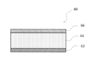
- FIG. 1 is a schematic cross-sectional view showing an example of the configuration of the electrodes according to the present embodiment.
- FIG. 2 is a schematic cross-sectional view showing an example of the configuration of the electrode according to the present embodiment.
- FIG. 3 is a schematic cross-sectional view of a non-aqueous electrolyte secondary battery which is an example of the embodiment.
- FIGS. 1 and 2 are schematic cross-sectional views showing an example of the configuration of the electrodes according to the present embodiment.
- the electrode 60 shown in FIGS. 1 and 2 is an electrode for a non-aqueous electrolyte secondary battery, and is applied to at least one of a positive electrode and a negative electrode of the non-aqueous electrolyte secondary battery.
- the electrodes 60 shown in FIGS. 1 and 2 include a current collector 62, an active material layer 64 formed on the current collector 62, and an aggregate 66 of filler particles existing on the surface of the active material layer 64. To be equipped.
- the aggregate 66 of the filler particles has an island shape.
- the aggregate 66 of the filler particles is in the form of a film and covers the entire surface of the active material layer 64.
- the aggregate 66 is a collection of a plurality of filler particles.
- the filler particles constituting the aggregate 66 are particles containing at least one of a compound containing boron oxide, potassium pyrosulfate, alkali metal or Br, and are transformed from a solid phase to a liquid phase or thermally.
- the decomposition point is in the range of 180 ° C to 650 ° C.
- the alkali metal or Br-containing compound contains at least one of borate, silicate, carbonate, bicarbonate, citrate and an aromatic compound.
- the rise in battery temperature in the nail piercing test is suppressed. This mechanism is not clear enough, but the following can be inferred. Due to the heat generated by the battery during the nail piercing test, that is, the heat generated by the battery when a nail is pierced into the battery to generate an internal short circuit in a simulated manner, the filler particles constituting the aggregate 66 are transformed from a solid phase to a liquid phase. Therefore, a film having high flame retardancy and low conductivity is formed on the surface of the active material layer 64.
- the coating film serves as a resistance component, and the amount of short-circuit current flowing between the positive and negative electrodes via the nail is suppressed, and as a result, the rise in battery temperature in the nail piercing test is also suppressed.
- the formation of the film after the transformation of the filler particles into the liquid phase is due to, for example, a heat fusion reaction, a dehydration condensation reaction, a heat polymerization reaction, or the like, although it depends on the type of the filler particles.
- an increase in battery resistance may be suppressed.
- the ionic conductivity of the filler material constituting the filler particles is not high, but in the case of the island-shaped aggregate 66 shown in FIG. 1, the gap between the aggregates 66 is a path through which ions such as lithium ions can easily pass. It is considered that ions such as lithium ions can move more smoothly between the negative electrodes, and an increase in battery resistance can be further suppressed.
- the borate containing an alkali metal or Br as filler particles is not particularly limited as long as the transformation point of transformation from a solid phase to a liquid phase or thermal decomposition is in the range of 180 ° C. to 650 ° C.
- alkali metal borate salts such as acid-sodium salt and borate-potassium salt.
- the silicate containing an alkali metal or Br as filler particles is not particularly limited as long as the transformation point of transformation from a solid phase to a liquid phase or thermal decomposition is in the range of 180 ° C. to 650 ° C., but for example.
- Silicic acid-alkali metal salts such as silicic acid-sodium salt, silicic acid-potassium salt and the like.
- the carbonate or bicarbonate containing alkali metal or Br as filler particles is not particularly limited as long as the transformation point of transformation from solid phase to liquid phase or thermal decomposition is in the range of 180 ° C. to 650 ° C.
- alkali metal carbonates such as potassium carbonate and sodium carbonate
- alkali metal hydrogen carbonates such as potassium hydrogen carbonate and sodium hydrogen carbonate
- carbonates containing Br such as BC-52 tetrabromobisphenol A
- the citrate containing an alkali metal or Br as filler particles is not particularly limited as long as the transformation point of transformation from a solid phase to a liquid phase or thermal decomposition is in the range of 180 ° C. to 650 ° C., but for example. , Citric acid alkali metal salts such as potassium citrate and sodium citrate.
- the aromatic compound containing an alkali metal or Br as filler particles is not particularly limited as long as the transformation point of transformation from a solid phase to a liquid phase or thermal decomposition is in the range of 180 ° C. to 650 ° C., but for example. , Ethylene-1,2-bis (pentabromophenyl), an aromatic compound containing an alkali metal such as ethylenebistetrabromophthalimide, an aromatic compound containing Br such as polybrominated diphenyl ether, and the like.
- the filler particles contain at least one of boron oxide, potassium pyrosulfate, Na, and K in terms of effectively suppressing an increase in battery temperature or an increase in battery resistance in a nail piercing test.
- a silicate containing at least one of acid acid, Na, and K, a carbonate containing at least one of Na and K, and a bicarbonate containing at least one of Na and K, A citrate containing at least one of Na and K and an aromatic compound containing Br are preferable, and boron oxide, potassium pyrosulfate, sodium silicate, potassium carbonate, potassium hydrogen carbonate, potassium citrate, and ethylene- 1,2-Bis (pentabromophenyl) and ethylenebistetrabromophthalimide are more preferable. These may be used alone or in combination of two or more.
- the transformation point of the filler particles may be in the range of 180 ° C. to 650 ° C., preferably 250 ° C. to 550 ° C. so that the filler particles are appropriately transformed from the solid phase to the liquid phase due to the heat generated by the battery in the nail piercing test.
- the range may be in the range of 180 ° C. to 650 ° C., preferably 250 ° C. to 550 ° C. so that the filler particles are appropriately transformed from the solid phase to the liquid phase due to the heat generated by the battery in the nail piercing test. The range.
- the coverage of the aggregate 66 on the surface of the active material layer 64 is preferably 90% or less, more preferably 60% or less, in terms of suppressing an increase in battery resistance.
- the coverage of the aggregate 66 on the surface of the active material layer 64 is preferably 5% or more, more preferably 10% or more, in terms of suppressing an increase in the battery temperature in the nail piercing test. In the case of the aggregate 66 shown in FIG. 2, the coverage of the aggregate 66 on the surface of the active material layer 64 is 100%.
- the coverage of the aggregate 66 is calculated as follows.
- the coverage is determined by elemental mapping of the electrode surface with SEM-EDX (Energy Dispersive X-ray spectroscopy) or the like.
- SEM-EDX Electromagnetic X-ray spectroscopy
- the coverage of the aggregate 66 on the surface of the active material layer 64 is calculated by elementally mapping the filler particles and the active material by element mapping.
- the average thickness of the island-shaped aggregate 66 shown in FIG. 1 is preferably 10 ⁇ m or less in terms of suppressing an increase in battery resistance. It should be noted that the thickness is preferably 0.3 ⁇ m or more in terms of suppressing an increase in the battery temperature in the nail piercing test.
- the average thickness of the film-like aggregate 66 shown in FIG. 2 is preferably 3 ⁇ m or less in terms of suppressing an increase in battery resistance, and 0.3 ⁇ m or more in terms of suppressing an increase in battery temperature in a nail piercing test. It is preferable to have.
- the average particle size of the filler particles is preferably 0.01 ⁇ m to 5 ⁇ m, more preferably 0.05 ⁇ m to 3 ⁇ m.
- the average particle size of the primary particles is determined as follows. First, 20 filler particles are randomly selected from the SEM image of the electrode surface.
- the major axis of each of the 20 filler particles is obtained, and the average value thereof is taken as the average particle size of the filler particles. To do.
- the aggregate 66 may contain a binder in addition to the filler particles described above. By including the binder, it is possible to improve the binding property between the filler particles and the binding property between the filler particles and the current collector 62.
- the binder is not particularly limited, and examples thereof include polyvinylidene fluoride (PVdF), ethylene dimethacrylate, allyl methacrylate, t-dodecylmerkabutane, ⁇ -methylstyrene dimer, and methacrylic acid.
- Polyvinylidene fluoride (PVdF), ethylene dimethacrylate, allyl methacrylate, t-dodecyl mercaptan, ⁇ -methylstyrene dimer, and methacrylic acid are electrodes of the aggregate 66 when pressure and / or heat is applied. 60 can be adhered to the separator 13. Further, the aggregate 66 may contain compound particles other than the above-mentioned filler particles. Examples of compound particles other than the above-mentioned filler particles include inorganic particles such as alumina, boehmite, and titania.
- the current collector 62 serving as the positive electrode current collector for example, a foil of a metal stable in the potential range of the positive electrode such as aluminum, a film in which the metal is arranged on the surface layer, or the like can be used. .. Further, the active material layer 64 to be the positive electrode active material layer contains a positive electrode active material, and preferably contains a conductive material or a binder.
- Examples of the positive electrode active material include lithium transition metal composite oxides, and specifically, lithium cobaltate, lithium manganate, lithium nickelate, lithium nickel-manganese composite oxide, lithium nickel-cobalt composite oxide and the like are used. Al, Ti, Zr, Nb, B, W, Mg, Mo and the like may be added to these lithium transition metal composite oxides.
- carbon powders such as carbon black, acetylene black, ketjen black, and graphite may be used alone or in combination of two or more.
- binder examples include fluororesins such as polytetrafluoroethylene (PTFE) and polyvinylidene fluoride (PVdF), polyacrylonitrile (PAN), polyimide resins, acrylic resins, and polyolefin resins. These may be used alone or in combination of two or more.
- fluororesins such as polytetrafluoroethylene (PTFE) and polyvinylidene fluoride (PVdF), polyacrylonitrile (PAN), polyimide resins, acrylic resins, and polyolefin resins. These may be used alone or in combination of two or more.
- a positive electrode mixture slurry containing a positive electrode active material, a binder, a conductive material, a solvent, etc. is applied onto the positive electrode current collector, the coating film is dried, and then rolled to form a positive electrode on the positive electrode current collector. Form an active material layer.
- a filler slurry containing filler particles, a binder, a solvent and the like is prepared. Then, the prepared filler slurry is sprayed, dropped or applied to the positive electrode active material layer and then dried to form an aggregate of filler particles existing on the surface of the positive electrode active material layer.
- the solvent contained in the slurry include water, N-methyl-2-pyrrolidone (NMP) and the like.
- the island-shaped aggregate shown in FIG. 1 can be formed, or the film-shaped aggregate shown in FIG. 2 can be formed. be able to.
- the island-like aggregate shown in FIG. 1 or the film-like aggregate shown in FIG. 2 can be formed.
- a masking sheet or the like provided with a plurality of through holes of a predetermined size is arranged on the positive electrode active material layer, and the filler slurry is placed on the arranged masking sheet.
- the current collector 62 serving as the negative electrode current collector for example, a metal foil stable in the potential range of the negative electrode such as copper, a film in which the metal is arranged on the surface layer, or the like can be used. ..
- the active material layer 64 to be the negative electrode active material layer contains a negative electrode active material, and preferably contains a binder or the like.
- a carbon material capable of storing and releasing lithium ions can be used, and in addition to graphite, non-graphite carbon, easily graphitable carbon, fibrous carbon, coke, carbon black and the like should be used. Can be done. Further, as the non-carbon material, silicon, tin, and alloys and oxides mainly containing these can be used.
- binder examples include fluororesin, PAN, polyimide resin, acrylic resin, polyolefin resin, styrene-butadiene rubber (SBR), nitrile-butadiene rubber (NBR), carboxymethyl cellulose (CMC) or a salt thereof.
- SBR styrene-butadiene rubber
- NBR nitrile-butadiene rubber
- CMC carboxymethyl cellulose
- PAA Polyacrylic acid
- PAA-Na, PAA-K, etc., or a partially neutralized salt polyvinyl alcohol (PVA), and the like. These may be used alone or in combination of two or more.
- a negative electrode mixture slurry containing a negative electrode active material, a binder, a solvent, etc. is applied onto the negative electrode current collector, the coating film is dried, and then rolled to obtain a negative electrode active material layer on the negative electrode current collector. To form.
- a filler slurry containing filler particles, a binder, a solvent, etc. is sprayed, dropped or applied to the negative electrode active material layer, and then dried to collect the filler particles existing on the surface of the negative electrode active material layer. Form the body.
- the method for obtaining an island-like aggregate or a film-like aggregate is as described above.
- FIG. 3 is a schematic cross-sectional view of a non-aqueous electrolyte secondary battery which is an example of the embodiment.
- the non-aqueous electrolyte secondary battery 10 shown in FIG. 3 has a wound electrode body 14 in which a positive electrode 11 and a negative electrode 12 are wound via a separator 13, a non-aqueous electrolyte, and above and below the electrode body 14, respectively.
- An arranged insulating plates 18 and 19 and a battery case 15 for accommodating the above members are provided.
- the battery case 15 is composed of a bottomed cylindrical case body 16 and a sealing body 17 that closes an opening of the case body 16.
- the winding type electrode body 14 instead of the winding type electrode body 14, another form of an electrode body such as a laminated type electrode body in which positive electrodes and negative electrodes are alternately laminated via a separator may be applied.
- the battery case 15 include a metal case such as a cylinder, a square, a coin, and a button, and a resin case (so-called laminated type) formed by laminating a resin sheet.
- the case body 16 is, for example, a bottomed cylindrical metal container.
- a gasket 28 is provided between the case body 16 and the sealing body 17 to ensure the airtightness inside the battery.
- the case body 16 has, for example, an overhanging portion 22 that supports the sealing body 17 with a part of the side surface overhanging inward.
- the overhanging portion 22 is preferably formed in an annular shape along the circumferential direction of the case body 16, and the sealing body 17 is supported on the upper surface thereof.
- the sealing body 17 has a structure in which a filter 23, a lower valve body 24, an insulating member 25, an upper valve body 26, and a cap 27 are laminated in this order from the electrode body 14 side.
- Each member constituting the sealing body 17 has, for example, a disk shape or a ring shape, and each member except the insulating member 25 is electrically connected to each other.
- the lower valve body 24 and the upper valve body 26 are connected to each other at the central portion thereof, and an insulating member 25 is interposed between the peripheral portions thereof.
- the lower valve body 24 When the internal pressure of the non-aqueous electrolyte secondary battery 10 rises due to heat generated by an internal short circuit or the like, for example, the lower valve body 24 is deformed and broken so as to push the upper valve body 26 toward the cap 27 side, and the lower valve body 24 and the upper valve are broken. The current path between the bodies 26 is cut off. When the internal pressure further rises, the upper valve body 26 breaks and gas is discharged from the opening of the cap 27.
- the positive electrode lead 20 attached to the positive electrode 11 extends to the sealing body 17 side through the through hole of the insulating plate 18, and the negative electrode lead 21 attached to the negative electrode 12 is insulated. It extends to the bottom side of the case body 16 through the outside of the plate 19.
- the positive electrode lead 20 is connected to the lower surface of the filter 23, which is the bottom plate of the sealing body 17, by welding or the like, and the cap 27, which is the top plate of the sealing body 17 electrically connected to the filter 23, serves as the positive electrode terminal.
- the negative electrode lead 21 is connected to the inner surface of the bottom of the case body 16 by welding or the like, and the case body 16 serves as a negative electrode terminal.
- the above-mentioned electrode 60 is applied to at least one of the positive electrode 11 and the negative electrode 12.
- a porous sheet or the like having ion permeability and insulating property is used.
- the porous sheet include a microporous thin film, a woven fabric, and a non-woven fabric.
- olefin resins such as polyethylene and polypropylene, cellulose and the like are suitable.
- the separator 13 may be a laminate having a cellulose fiber layer and a thermoplastic resin fiber layer such as an olefin resin.
- a multilayer separator containing a polyethylene layer and a polypropylene layer may be used, or a separator 13 coated with a material such as an aramid resin or ceramic may be used.
- the non-aqueous electrolyte contains a non-aqueous solvent and an electrolyte salt dissolved in the non-aqueous solvent.
- the non-aqueous solvent for example, esters, ethers, nitriles, amides, and a mixed solvent of two or more of these are used.
- the non-aqueous solvent may contain a halogen substituent in which at least a part of hydrogen in these solvents is substituted with a halogen atom such as fluorine.
- the electrolyte salt for example, a lithium salt such as LiPF 6 is used.
- Example> [Preparation of positive electrode] 100 parts by weight of the positive electrode active material represented by LiNi 0.82 Co 0.15 Al 0.03 O 2 , 1 part by weight of acetylene black (AB), and 1 part by weight of polyvinylidene fluoride (PVdF). After mixing, an appropriate amount of N-methyl-2-pyrrolidone (NMP) was added to prepare a positive electrode mixture slurry. Next, the positive electrode mixture slurry was applied to both sides of the positive electrode current collector made of aluminum foil and dried. This was cut into a predetermined electrode size and rolled using a roller to form positive electrode active material layers on both sides of the positive electrode current collector.
- NMP N-methyl-2-pyrrolidone
- Example 1 94 parts by weight of sodium silicate (Na 2 SiO 3 ) particles and 6 parts by weight of polyvinylidene fluoride (PVdF) were mixed, and 400 parts by weight of N-methyl-2-pyrrolidone (NMP) was further added. , A slurry for filler was prepared. The filler particles were applied to the entire surface of the positive electrode active material layer so as to be 4 g / m 2, and dried. This was used as the positive electrode of Example 1.
- Na 2 SiO 3 sodium silicate
- PVdF polyvinylidene fluoride
- NMP N-methyl-2-pyrrolidone
- LiPF 6 Lithium hexafluorophosphate
- EC ethylene carbonate
- EMC ethyl methyl carbonate
- DMC dimethyl carbonate
- Example 2 A non-aqueous electrolyte secondary battery was prepared in the same manner as in Example 1 except that sodium silicate (Na 2 SiO 3 ) was replaced with potassium pyrosulfate (K 2 S 2 O 7 ) particles in the preparation of the filler slurry. did.
- sodium silicate Na 2 SiO 3
- potassium pyrosulfate K 2 S 2 O 7
- Example 3 A non-aqueous electrolyte secondary battery was produced in the same manner as in Example 1 except that sodium silicate (Na 2 SiO 3 ) was replaced with boron oxide (B 2 O 3 ) particles in the preparation of the filler slurry.
- sodium silicate (Na 2 SiO 3 ) was replaced with boron oxide (B 2 O 3 ) particles in the preparation of the filler slurry.
- B 2 O 3 boron oxide
- Example 4 A non-aqueous electrolyte secondary battery was used in the same manner as in Example 1 except that sodium silicate (Na 2 SiO 3 ) was replaced with ethylene-1,2-bis (pentabromophenyl) particles in the preparation of the filler slurry. Made. When the surface of the positive electrode of Example 4 was observed by SEM-EDX, the distribution of ethylene-1,2-bis (pentabromophenyl) particles was confirmed, and the distribution of ethylene-1,2-bis (pentabromophenyl) particles was confirmed. The coverage was 30%.
- Example 5 A non-aqueous electrolyte secondary battery was produced in the same manner as in Example 1 except that sodium silicate (Na 2 SiO 3 ) was replaced with ethylene bistetrabromophthalimide particles in the preparation of the filler slurry.
- sodium silicate Na 2 SiO 3
- ethylene bistetrabromophthalimide particles in the preparation of the filler slurry.
- Example 6 Non-aqueous electrolyte secondary battery as in Example 1 except that sodium silicate (Na 2 SiO 3 ) was replaced with potassium citrate (C 6 H 5 K 3 O 7 ) particles in the preparation of the filler slurry. was produced.
- sodium silicate Na 2 SiO 3
- potassium citrate C 6 H 5 K 3 O 7
- Example 7 A non-aqueous electrolyte secondary battery was produced in the same manner as in Example 1 except that sodium silicate (Na 2 SiO 3 ) was replaced with potassium carbonate (K 2 CO 3 ) particles in the preparation of the filler slurry.
- sodium silicate (Na 2 SiO 3 ) was replaced with potassium carbonate (K 2 CO 3 ) particles in the preparation of the filler slurry.
- K 2 CO 3 potassium carbonate
- Example 8> A non-aqueous electrolyte secondary battery was produced in the same manner as in Example 1 except that sodium silicate (Na 2 SiO 3 ) was replaced with sodium carbonate (Na 2 CO 3 ) particles in the preparation of the filler slurry.
- sodium silicate Na 2 SiO 3
- sodium carbonate Na 2 CO 3
- the surface of the positive electrode of Example 8 was observed by SEM-EDX, the distribution of sodium carbonate (Na 2 CO 3 ) particles was confirmed, and the coverage of the aggregate of sodium carbonate (Na 2 CO 3) particles was 30%. Met.
- Example 9 94 parts by weight of potassium citrate (C 6 H 5 K 3 O 7 ) particles and 60 parts by weight of polyvinylidene fluoride (PVdF) are mixed, and 25 parts by weight of N-methyl-2-pyrrolidone (NMP) is added.
- NMP N-methyl-2-pyrrolidone
- a non-aqueous electrolyte secondary battery was produced in the same manner as in Example 1 except that this was used as the positive electrode of Example 9.
- the coverage of potassium citrate (C 6 H 5 K 3 O 7 ) particles was 100%.
- the coverage rate of 100% is a state in which (strength of the active material component) / (strength of the filler particle component) is the lower limit of detection when elemental mapping is performed by SEM-EDX.
- Example 1 A non-aqueous electrolyte secondary battery was produced in the same manner as in Example 1 except that the filler slurry was not used.
- the battery resistance of the non-aqueous electrolyte secondary batteries of Examples 1 to 9 and Comparative Example 1 was measured as follows. In a temperature environment of 25 ° C., the non-aqueous electrolyte secondary battery is charged with a constant current of 0.3 C until the battery voltage reaches 4.2 V, and then charged with a constant voltage until the current value reaches 0.05 C. Then, it was discharged with a constant current of 0.3C to set the SOC to 50%. Next, the voltage values when the discharge currents of 0A, 0.1A, 0.5A, and 1.0A were applied for 10 seconds were acquired. DC-IR was calculated from the absolute value of the slope when the voltage value after 10 seconds for each discharge current value was linearly approximated by the least squares method, and this value is summarized in Table 1 as the battery resistance.
- Non-aqueous electrolyte secondary battery 11 Positive electrode 12 Negative electrode 13 Separator 14 Electrode body 15 Battery case 16 Case body 17 Sealing body 18, 19 Insulating plate 20 Positive electrode lead 21 Negative electrode lead 22 Overhanging part 23 Filter 24 Lower valve body 25 Insulating member 26 Upper valve body 27 Cap 28 Gasket 60 Electrode 62 Current collector 64 Active material layer 66 Aggregate
Landscapes
- Chemical & Material Sciences (AREA)
- Chemical Kinetics & Catalysis (AREA)
- Electrochemistry (AREA)
- General Chemical & Material Sciences (AREA)
- Engineering & Computer Science (AREA)
- Materials Engineering (AREA)
- Manufacturing & Machinery (AREA)
- Battery Electrode And Active Subsutance (AREA)
- Secondary Cells (AREA)
Abstract
This electrode for nonaqueous electrolyte secondary batteries is provided with a collector, an active material layer that is formed on the collector, and an assembly of filler particles, said assembly being present on the surface of the active material layer. The filler particles contain at least one of boron oxide, potassium pyrosulfate and a compound containing an alkali metal or Br, while having a transformation point, at which the filler particles undergo a transformation from a solid phase to a liquid phase or a thermal decomposition, within the range of from 180°C to 650°C. The compound containing an alkali metal or Br contains at least one of a borate, a silicate, a carbonate, a hydrogen carbonate, a citrate or an aromatic compound.
Description
本開示は、非水電解質二次電池用電極及び非水電解質二次電池に関する。
The present disclosure relates to electrodes for non-aqueous electrolyte secondary batteries and non-aqueous electrolyte secondary batteries.
近年、高出力、高エネルギー密度の二次電池として、正極と負極との間でリチウムイオンを移動させて充放電を行う非水電解質二次電池が広く利用されている。
In recent years, as a secondary battery with high output and high energy density, a non-aqueous electrolyte secondary battery that charges and discharges by moving lithium ions between the positive electrode and the negative electrode has been widely used.
ところで、電池の内部短絡に対する耐性を確認する安全性評価試験として、釘刺し試験がある。釘刺し試験とは、たとえば、電池に釘を突き刺して内部短絡を模擬的に発生させ、発熱の度合を調べて電池の安全性を確認する試験である。このような釘刺し時における電池の発熱を抑制することは、電池の安全性を確保する点で重要である。
By the way, there is a nail piercing test as a safety evaluation test to confirm the resistance of the battery to internal short circuit. The nail piercing test is, for example, a test in which a nail is pierced into a battery to generate an internal short circuit in a simulated manner, and the degree of heat generation is examined to confirm the safety of the battery. It is important to suppress the heat generation of the battery at the time of such nail sticking in order to ensure the safety of the battery.
例えば、特許文献1には、正極や負極の極板表面に、リン含有化合物、窒素含有化合物及び無機ケイ素類化合物から選択される機能性物質を含むコーティング層を配置することにより、釘刺し試験における電池の発熱を抑制する技術が開示されている。
For example, in Patent Document 1, a coating layer containing a functional substance selected from a phosphorus-containing compound, a nitrogen-containing compound, and an inorganic silicon compound is arranged on the surface of the electrode plate of a positive electrode or a negative electrode, thereby performing a nail piercing test. A technique for suppressing heat generation of a battery is disclosed.
例えば、特許文献2には、正極と負極との間にポリリン酸塩を含む中間層を配置することにより、電池の異常発熱時の温度上昇を抑制する技術が開示されている。
For example, Patent Document 2 discloses a technique of suppressing a temperature rise at the time of abnormal heat generation of a battery by arranging an intermediate layer containing a polyphosphate between a positive electrode and a negative electrode.
特許文献1及び2のように、極板表面に機能性物質のコーティング層を配置したりポリリン酸塩の中間層を配置したりすると、これらの層が抵抗となって、電池抵抗が上昇する懸念がある。
When a coating layer of a functional substance or an intermediate layer of polyphosphate is arranged on the surface of the electrode plate as in Patent Documents 1 and 2, there is a concern that these layers become resistance and the battery resistance increases. There is.
本開示の一態様に係る非水電解質二次電池用電極は、集電体と、前記集電体上に形成された活物質層と、前記活物質層の表面上に存在するフィラー粒子の集合体と、を備え、前記フィラー粒子は、ホウ素酸化物、ピロ硫酸カリウム、アルカリ金属又はBrを含有す化合物のうち少なくともいずれか1つを含む粒子であって、固相から液相へ変態する或いは熱分解する変態点が180℃~650℃の範囲であり、前記アルカリ金属又はBrを含有する化合物は、ホウ酸塩、ケイ酸塩、炭酸塩、炭酸水素塩、クエン酸塩及び芳香族化合物のうちの少なくともいずれか1つを含む。
The electrode for a non-aqueous electrolyte secondary battery according to one aspect of the present disclosure is a collection of a current collector, an active material layer formed on the current collector, and filler particles existing on the surface of the active material layer. The filler particles are particles containing at least one of a compound containing a boron oxide, potassium pyrosulfate, alkali metal or Br, and transform from a solid phase to a liquid phase. The transformation point for thermal decomposition is in the range of 180 ° C. to 650 ° C., and the alkali metal or Br-containing compound is a borate, silicate, carbonate, hydrogen carbonate, citrate and aromatic compound. Includes at least one of them.
本開示の一態様に係る非水電解質二次電池は、正極と負極とを有し、前記正極及び前記負極のうち少なくともいずれか一方は、前記非水電解質二次電池用電極である。
The non-aqueous electrolyte secondary battery according to one aspect of the present disclosure has a positive electrode and a negative electrode, and at least one of the positive electrode and the negative electrode is the electrode for the non-aqueous electrolyte secondary battery.
本開示によれば、釘刺し試験における電池の発熱を抑制することが可能となる。
According to the present disclosure, it is possible to suppress the heat generation of the battery in the nail piercing test.
以下、図面に基づき本開示における実施形態について説明する。
Hereinafter, embodiments in the present disclosure will be described based on the drawings.
図1及び図2は、本実施形態に係る電極の構成の一例を示す模式断面図である。図1及び図2に示す電極60は、非水電解質二次電池用電極であり、非水電解質二次電池の正極及び負極のうち少なくともいずれか一方に適用される。
1 and 2 are schematic cross-sectional views showing an example of the configuration of the electrodes according to the present embodiment. The electrode 60 shown in FIGS. 1 and 2 is an electrode for a non-aqueous electrolyte secondary battery, and is applied to at least one of a positive electrode and a negative electrode of the non-aqueous electrolyte secondary battery.
図1及び図2に示す電極60は、集電体62と、集電体62上に形成された活物質層64と、活物質層64の表面上に存在するフィラー粒子の集合体66と、を備える。図1に示す電極60では、フィラー粒子の集合体66が、アイランド状になっている。一方、図2に示す電極60では、フィラー粒子の集合体66が、膜状になっており、活物質層64の表面全体を覆っている。集合体66は、複数のフィラー粒子が寄せ集まったものである。
The electrodes 60 shown in FIGS. 1 and 2 include a current collector 62, an active material layer 64 formed on the current collector 62, and an aggregate 66 of filler particles existing on the surface of the active material layer 64. To be equipped. In the electrode 60 shown in FIG. 1, the aggregate 66 of the filler particles has an island shape. On the other hand, in the electrode 60 shown in FIG. 2, the aggregate 66 of the filler particles is in the form of a film and covers the entire surface of the active material layer 64. The aggregate 66 is a collection of a plurality of filler particles.
集合体66を構成するフィラー粒子は、ホウ素酸化物、ピロ硫酸カリウム、アルカリ金属又はBrを含有する化合物のうち少なくともいずれか1つを含む粒子であって、固相から液相へ変態する或いは熱分解する変態点が180℃~650℃の範囲である。但し、上記アルカリ金属又はBrを含有する化合物は、ホウ酸塩、ケイ酸塩、炭酸塩、炭酸水素塩、クエン酸塩及び芳香族化合物のうちの少なくともいずれか1つを含む。
The filler particles constituting the aggregate 66 are particles containing at least one of a compound containing boron oxide, potassium pyrosulfate, alkali metal or Br, and are transformed from a solid phase to a liquid phase or thermally. The decomposition point is in the range of 180 ° C to 650 ° C. However, the alkali metal or Br-containing compound contains at least one of borate, silicate, carbonate, bicarbonate, citrate and an aromatic compound.
本実施形態に係る非水電解質二次電池用電極を使用することにより、釘刺し試験における電池温度の上昇が抑制される。このメカニズムは、十分に明らかでないが、以下のことが推察される。釘刺し試験時の電池の発熱、すなわち、電池に釘を突き刺して内部短絡を模擬的に発生させた時の電池の発熱により、集合体66を構成するフィラー粒子は固相から液相に変態して、活物質層64の表面上に、難燃性が高く、導電性の低い被膜が形成される。そして、当該被膜が抵抗成分となって、釘を介した正負極間に流れる短絡電流の電流量が抑えられ、その結果、釘刺し試験における電池温度の上昇も抑えられる。なお、フィラー粒子の液相への変態後の被膜形成は、フィラー粒子の種類にもよるが、例えば、熱融着反応、脱水縮合反応、熱重合反応等によるものである。
By using the electrode for the non-aqueous electrolyte secondary battery according to the present embodiment, the rise in battery temperature in the nail piercing test is suppressed. This mechanism is not clear enough, but the following can be inferred. Due to the heat generated by the battery during the nail piercing test, that is, the heat generated by the battery when a nail is pierced into the battery to generate an internal short circuit in a simulated manner, the filler particles constituting the aggregate 66 are transformed from a solid phase to a liquid phase. Therefore, a film having high flame retardancy and low conductivity is formed on the surface of the active material layer 64. Then, the coating film serves as a resistance component, and the amount of short-circuit current flowing between the positive and negative electrodes via the nail is suppressed, and as a result, the rise in battery temperature in the nail piercing test is also suppressed. The formation of the film after the transformation of the filler particles into the liquid phase is due to, for example, a heat fusion reaction, a dehydration condensation reaction, a heat polymerization reaction, or the like, although it depends on the type of the filler particles.
また、本実施形態に係る非水電解質二次電池用電極によれば、電池抵抗の上昇が抑制できる場合がある。このメカニズムは、十分に明らかでないが、以下のことが推察される。フィラー粒子を構成するフィラー材料のイオン伝導性は高くないが、図1に示すアイランド状の集合体66の場合、集合体66間の隙間がリチウムイオン等のイオンが通り易い経路となるため、正負極間をリチウムイオン等のイオンがよりスムーズに移動することができ、電池抵抗の上昇がより抑えられると考えられる。
Further, according to the electrode for a non-aqueous electrolyte secondary battery according to the present embodiment, an increase in battery resistance may be suppressed. This mechanism is not clear enough, but the following can be inferred. The ionic conductivity of the filler material constituting the filler particles is not high, but in the case of the island-shaped aggregate 66 shown in FIG. 1, the gap between the aggregates 66 is a path through which ions such as lithium ions can easily pass. It is considered that ions such as lithium ions can move more smoothly between the negative electrodes, and an increase in battery resistance can be further suppressed.
以下、電極60の構成材料について、さらに詳述する。
Hereinafter, the constituent materials of the electrode 60 will be described in more detail.
フィラー粒子としてのアルカリ金属又はBrを含有するホウ酸塩は、固相から液相へ変態する或いは熱分解する変態点が180℃~650℃の範囲であれば、特に限定されないが、例えば、ホウ酸-ナトリウム塩、ホウ酸-カリウム塩等のホウ酸アルカリ金属塩等が挙げられる。
The borate containing an alkali metal or Br as filler particles is not particularly limited as long as the transformation point of transformation from a solid phase to a liquid phase or thermal decomposition is in the range of 180 ° C. to 650 ° C. Examples thereof include alkali metal borate salts such as acid-sodium salt and borate-potassium salt.
また、フィラー粒子としてのアルカリ金属又はBrを含有するケイ酸塩は、固相から液相へ変態する或いは熱分解する変態点が180℃~650℃の範囲であれば、特に限定されないが、例えば、ケイ酸-ナトリウム塩、ケイ酸-カリウム塩等のケイ酸アルカリ金属塩等が挙げられる。
The silicate containing an alkali metal or Br as filler particles is not particularly limited as long as the transformation point of transformation from a solid phase to a liquid phase or thermal decomposition is in the range of 180 ° C. to 650 ° C., but for example. , Silicic acid-alkali metal salts such as silicic acid-sodium salt, silicic acid-potassium salt and the like.
また、フィラー粒子としてのアルカリ金属又はBrを含有する炭酸塩、炭酸水素塩は、固相から液相へ変態する或いは熱分解する変態点が180℃~650℃の範囲であれば、特に限定されないが、例えば、炭酸カリウム、炭酸ナトリウム等のアルカリ金属炭酸塩、炭酸水素カリウム、炭酸水素ナトリウム等のアルカリ金属炭酸水素塩、BC-52テトラブロモビスフェノールA等のBrを含む炭酸塩等が挙げられる。
The carbonate or bicarbonate containing alkali metal or Br as filler particles is not particularly limited as long as the transformation point of transformation from solid phase to liquid phase or thermal decomposition is in the range of 180 ° C. to 650 ° C. However, for example, alkali metal carbonates such as potassium carbonate and sodium carbonate, alkali metal hydrogen carbonates such as potassium hydrogen carbonate and sodium hydrogen carbonate, and carbonates containing Br such as BC-52 tetrabromobisphenol A can be mentioned.
また、フィラー粒子としてのアルカリ金属又はBrを含有するクエン酸塩は、固相から液相へ変態する或いは熱分解する変態点が180℃~650℃の範囲であれば、特に限定されないが、例えば、クエン酸カリウム、クエン酸ナトリウム等のクエン酸アルカリ金属塩等が挙げられる。
The citrate containing an alkali metal or Br as filler particles is not particularly limited as long as the transformation point of transformation from a solid phase to a liquid phase or thermal decomposition is in the range of 180 ° C. to 650 ° C., but for example. , Citric acid alkali metal salts such as potassium citrate and sodium citrate.
また、フィラー粒子としてのアルカリ金属又はBrを含有する芳香族化合物は、固相から液相へ変態する或いは熱分解する変態点が180℃~650℃の範囲であれば、特に限定されないが、例えば、エチレン-1,2-ビス(ペンタブロモフェニル)、エチレンビステトラブロモフタルイミド等のアルカリ金属を含む芳香族化合物、ポリ臭化ジフェニルエーテル等のBrを含む芳香族化合物等が挙げられる。
The aromatic compound containing an alkali metal or Br as filler particles is not particularly limited as long as the transformation point of transformation from a solid phase to a liquid phase or thermal decomposition is in the range of 180 ° C. to 650 ° C., but for example. , Ethylene-1,2-bis (pentabromophenyl), an aromatic compound containing an alkali metal such as ethylenebistetrabromophthalimide, an aromatic compound containing Br such as polybrominated diphenyl ether, and the like.
フィラー粒子としては、釘刺し試験における電池温度の上昇又は電池抵抗の上昇を効果的に抑制する等の点で、ホウ素酸化物、ピロ硫酸カリウム、Na、Kのうちの少なくともいずれか一方を含むホウ酸塩、Na、Kのうちの少なくともいずれか一方を含むケイ酸塩、Na、Kのうちの少なくともいずれか一方を含む炭酸塩、Na、Kのうちの少なくともいずれか一方を含む炭酸水素塩、Na、Kのうちの少なくともいずれか一方を含むクエン酸塩、Brを含む芳香族化合物が好ましく、ホウ素酸化物、ピロ硫酸カリウム、ケイ酸ナトリウム、炭酸カリウム、炭酸水素カリウム、クエン酸カリウム、エチレン-1,2-ビス(ペンタブロモフェニル)、エチレンビステトラブロモフタルイミドがより好ましい。これらは1種単独でもよいし、2種以上を併用してもよい。
The filler particles contain at least one of boron oxide, potassium pyrosulfate, Na, and K in terms of effectively suppressing an increase in battery temperature or an increase in battery resistance in a nail piercing test. A silicate containing at least one of acid acid, Na, and K, a carbonate containing at least one of Na and K, and a bicarbonate containing at least one of Na and K, A citrate containing at least one of Na and K and an aromatic compound containing Br are preferable, and boron oxide, potassium pyrosulfate, sodium silicate, potassium carbonate, potassium hydrogen carbonate, potassium citrate, and ethylene- 1,2-Bis (pentabromophenyl) and ethylenebistetrabromophthalimide are more preferable. These may be used alone or in combination of two or more.
フィラー粒子の変態点は、釘刺し試験による電池の発熱により、適切に固相から液相に変態するように、180℃~650℃の範囲であればよいが、好ましくは250℃~550℃の範囲である。
The transformation point of the filler particles may be in the range of 180 ° C. to 650 ° C., preferably 250 ° C. to 550 ° C. so that the filler particles are appropriately transformed from the solid phase to the liquid phase due to the heat generated by the battery in the nail piercing test. The range.
活物質層64の表面に対する集合体66の被覆率は、電池抵抗の上昇を抑える点で、90%以下が好ましく、60%以下がより好ましい。また、活物質層64の表面に対する集合体66の被覆率は、釘刺し試験における電池温度の上昇を抑える点で、5%以上が好ましく、10%以上がより好ましい。なお、図2に示す集合体66の場合、活物質層64の表面に対する集合体66の被覆率は100%である。集合体66の被覆率は、以下のようにして算出される。
The coverage of the aggregate 66 on the surface of the active material layer 64 is preferably 90% or less, more preferably 60% or less, in terms of suppressing an increase in battery resistance. The coverage of the aggregate 66 on the surface of the active material layer 64 is preferably 5% or more, more preferably 10% or more, in terms of suppressing an increase in the battery temperature in the nail piercing test. In the case of the aggregate 66 shown in FIG. 2, the coverage of the aggregate 66 on the surface of the active material layer 64 is 100%. The coverage of the aggregate 66 is calculated as follows.
被覆率は、SEM-EDX(Energy Dispersive X-ray spectrometry)等により、電極表面の元素マッピングを行うことで求められる。例えば、元素マッピングにより、フィラー粒子と活物質を元素マッピングすることにより、活物質層64の表面に対する集合体66の被覆率を算出する。
The coverage is determined by elemental mapping of the electrode surface with SEM-EDX (Energy Dispersive X-ray spectroscopy) or the like. For example, the coverage of the aggregate 66 on the surface of the active material layer 64 is calculated by elementally mapping the filler particles and the active material by element mapping.
図1に示すアイランド状の集合体66の平均厚みは、電池抵抗の上昇を抑える点で、10μm以下であることが好ましい。なお、釘刺し試験における電池温度の上昇を抑える点で、0.3μm以上であることが好ましい。図2に示す膜状の集合体66の平均厚みは、電池抵抗の上昇を抑える点で、3μm以下であることが好ましく、釘刺し試験における電池温度の上昇を抑える点で、0.3μm以上であることが好ましい。
The average thickness of the island-shaped aggregate 66 shown in FIG. 1 is preferably 10 μm or less in terms of suppressing an increase in battery resistance. It should be noted that the thickness is preferably 0.3 μm or more in terms of suppressing an increase in the battery temperature in the nail piercing test. The average thickness of the film-like aggregate 66 shown in FIG. 2 is preferably 3 μm or less in terms of suppressing an increase in battery resistance, and 0.3 μm or more in terms of suppressing an increase in battery temperature in a nail piercing test. It is preferable to have.
フィラー粒子の平均粒径は、0.01μm~5μmであることが好ましく、0.05μm~3μmの範囲であることがより好ましい。フィラー粒子の平均粒径が上記範囲を満たすことで、上記範囲を満たさない場合と比較して、釘刺し試験時の電池の発熱により、フィラー粒子が固相から液相へ速やかに変態するため、釘刺し試験における電池温度の上昇を効果的に抑えられる。一次粒子の平均粒径は以下のようにして求められる。まず、電極表面のSEM画像から、ランダムに20個のフィラー粒子を選択する。次に、選択した20個のフィラー粒子の粒界を観察し、フィラー粒子の外形を特定した上で、20個のフィラー粒子それぞれの長径を求め、それらの平均値をフィラー粒子の平均粒径とする。
The average particle size of the filler particles is preferably 0.01 μm to 5 μm, more preferably 0.05 μm to 3 μm. When the average particle size of the filler particles satisfies the above range, the filler particles are rapidly transformed from the solid phase to the liquid phase due to the heat generated by the battery during the nail piercing test, as compared with the case where the above range is not satisfied. The rise in battery temperature in the nail piercing test can be effectively suppressed. The average particle size of the primary particles is determined as follows. First, 20 filler particles are randomly selected from the SEM image of the electrode surface. Next, after observing the grain boundaries of the selected 20 filler particles and specifying the outer shape of the filler particles, the major axis of each of the 20 filler particles is obtained, and the average value thereof is taken as the average particle size of the filler particles. To do.
集合体66は、前述のフィラー粒子の他に、結着材を含んでいてもよい。結着材を含むことにより、フィラー粒子同士の結着性やフィラー粒子と集電体62との結着性を向上させることができる。結着材は、特に限定されないが、例えば、ポリフッ化ビニリデン(PVdF)、エチレンジメタクリレート、メタクリル酸アリル、t-ドデシルメルカブタン、α-メチルスチレンダイマー、メタアクリル酸等が挙げられる。なお、ポリフッ化ビニリデン(PVdF)、エチレンジメタクリレート、メタクリル酸アリル、t-ドデシルメルカブタン、α-メチルスチレンダイマー、メタアクリル酸は、集合体66に圧力及び/又は熱が加えられることで、電極60をセパレータ13に接着させ得る。また、集合体66は、前述のフィラー粒子以外の化合物粒子を含んでいてもよい。前述のフィラー粒子以外の化合物粒子は、例えば、アルミナ、ベーマイト、チタニア等の無機粒子が挙げられる。
The aggregate 66 may contain a binder in addition to the filler particles described above. By including the binder, it is possible to improve the binding property between the filler particles and the binding property between the filler particles and the current collector 62. The binder is not particularly limited, and examples thereof include polyvinylidene fluoride (PVdF), ethylene dimethacrylate, allyl methacrylate, t-dodecylmerkabutane, α-methylstyrene dimer, and methacrylic acid. Polyvinylidene fluoride (PVdF), ethylene dimethacrylate, allyl methacrylate, t-dodecyl mercaptan, α-methylstyrene dimer, and methacrylic acid are electrodes of the aggregate 66 when pressure and / or heat is applied. 60 can be adhered to the separator 13. Further, the aggregate 66 may contain compound particles other than the above-mentioned filler particles. Examples of compound particles other than the above-mentioned filler particles include inorganic particles such as alumina, boehmite, and titania.
電極60を正極として用いる場合、正極集電体となる集電体62は、例えば、アルミニウムなどの正極の電位範囲で安定な金属の箔、当該金属を表層に配置したフィルム等を用いることができる。また、正極活物質層となる活物質層64は、正極活物質を含み、また、導電材や結着材を含むことが好適である。
When the electrode 60 is used as the positive electrode, as the current collector 62 serving as the positive electrode current collector, for example, a foil of a metal stable in the potential range of the positive electrode such as aluminum, a film in which the metal is arranged on the surface layer, or the like can be used. .. Further, the active material layer 64 to be the positive electrode active material layer contains a positive electrode active material, and preferably contains a conductive material or a binder.
正極活物質としては、リチウム遷移金属複合酸化物等が挙げられ、具体的にはコバルト酸リチウム、マンガン酸リチウム、ニッケル酸リチウム、リチウムニッケルマンガン複合酸化物、リチウムニッケルコバルト複合酸化物等を用いることができ、これらのリチウム遷移金属複合酸化物にAl、Ti、Zr、Nb、B、W、Mg、Mo等を添加してもよい。
Examples of the positive electrode active material include lithium transition metal composite oxides, and specifically, lithium cobaltate, lithium manganate, lithium nickelate, lithium nickel-manganese composite oxide, lithium nickel-cobalt composite oxide and the like are used. Al, Ti, Zr, Nb, B, W, Mg, Mo and the like may be added to these lithium transition metal composite oxides.
導電材としては、カーボンブラック、アセチレンブラック、ケッチェンブラック、黒鉛等の炭素粉末を単独で、あるいは2種以上組み合わせて用いてもよい。
As the conductive material, carbon powders such as carbon black, acetylene black, ketjen black, and graphite may be used alone or in combination of two or more.
結着材としては、例えば、ポリテトラフルオロエチレン(PTFE)、ポリフッ化ビニリデン(PVdF)等のフッ素系樹脂、ポリアクリロニトリル(PAN)、ポリイミド系樹脂、アクリル系樹脂、ポリオレフィン系樹脂などが挙げられる。これらは、単独で用いてもよく、2種類以上を組み合わせて用いてもよい。
Examples of the binder include fluororesins such as polytetrafluoroethylene (PTFE) and polyvinylidene fluoride (PVdF), polyacrylonitrile (PAN), polyimide resins, acrylic resins, and polyolefin resins. These may be used alone or in combination of two or more.
正極の作製方法の一例を説明する。まず、正極活物質、結着材、導電材、溶媒等を含む正極合材スラリーを正極集電体上に塗布し、塗膜を乾燥させた後、圧延して、正極集電体上に正極活物質層を形成する。次に、フィラー粒子、結着材、溶媒等を含むフィラー用スラリーを調製する。そして、調製したフィラー用スラリーを正極活物質層に、噴霧、滴下又は塗布した後、乾燥して、正極活物質層の表面上に存在するフィラー粒子の集合体を形成する。スラリーに含まれる溶媒は、例えば、水、N-メチル-2-ピロリドン(NMP)等が挙げられる。
An example of a method for manufacturing a positive electrode will be described. First, a positive electrode mixture slurry containing a positive electrode active material, a binder, a conductive material, a solvent, etc. is applied onto the positive electrode current collector, the coating film is dried, and then rolled to form a positive electrode on the positive electrode current collector. Form an active material layer. Next, a filler slurry containing filler particles, a binder, a solvent and the like is prepared. Then, the prepared filler slurry is sprayed, dropped or applied to the positive electrode active material layer and then dried to form an aggregate of filler particles existing on the surface of the positive electrode active material layer. Examples of the solvent contained in the slurry include water, N-methyl-2-pyrrolidone (NMP) and the like.
ここで、例えばフィラー用スラリーに含まれるフィラー粒子と溶媒の量を調製することで、図1に示すアイランド状の集合体を形成したり、図2に示す膜状の集合体を形成したりすることができる。図1に示すアイランド状の集合体を形成する場合には、例えば、溶媒100mlに対してフィラー粒子を10~60%添加することが好ましい。図2に示すアイランド状の集合体を形成する場合には、例えば、溶媒100mlに対してフィラー粒子を80%以上添加することが好ましい。また、例えば、フィラー用スラリーの噴霧量、滴下量又は塗布量を制御することによっても、図1に示すアイランド状の集合体を形成したり、図2に示す膜状の集合体を形成したりすることができる。また、図1に示すアイランド状の集合体は、例えば、所定のサイズの貫通穴が複数設けられたマスキングシート等を正極活物質層上に配置して、配置したマスキングシートの上からフィラー用スラリーを噴霧、滴下又は塗布等をすることによっても得られる。
Here, for example, by adjusting the amounts of the filler particles and the solvent contained in the filler slurry, the island-shaped aggregate shown in FIG. 1 can be formed, or the film-shaped aggregate shown in FIG. 2 can be formed. be able to. When forming the island-shaped aggregate shown in FIG. 1, for example, it is preferable to add 10 to 60% of filler particles to 100 ml of the solvent. When forming the island-shaped aggregate shown in FIG. 2, for example, it is preferable to add 80% or more of the filler particles to 100 ml of the solvent. Further, for example, by controlling the spray amount, the dropping amount, or the coating amount of the filler slurry, the island-like aggregate shown in FIG. 1 or the film-like aggregate shown in FIG. 2 can be formed. can do. Further, in the island-shaped aggregate shown in FIG. 1, for example, a masking sheet or the like provided with a plurality of through holes of a predetermined size is arranged on the positive electrode active material layer, and the filler slurry is placed on the arranged masking sheet. Can also be obtained by spraying, dropping or coating.
電極60を負極として用いる場合、負極集電体となる集電体62は、例えば、銅などの負極の電位範囲で安定な金属の箔、当該金属を表層に配置したフィルム等を用いることができる。また、負極活物質層となる活物質層64は、負極活物質を含み、また、結着材等を含むことが好適である。
When the electrode 60 is used as the negative electrode, as the current collector 62 serving as the negative electrode current collector, for example, a metal foil stable in the potential range of the negative electrode such as copper, a film in which the metal is arranged on the surface layer, or the like can be used. .. Further, the active material layer 64 to be the negative electrode active material layer contains a negative electrode active material, and preferably contains a binder or the like.
負極活物質としては、リチウムイオンの吸蔵・放出が可能な炭素材料を用いることができ、黒鉛の他に、難黒鉛性炭素、易黒鉛性炭素、繊維状炭素、コークス及びカーボンブラック等を用いることができる。さらに、非炭素系材料として、シリコン、スズ及びこれらを主とする合金や酸化物を用いることができる。
As the negative electrode active material, a carbon material capable of storing and releasing lithium ions can be used, and in addition to graphite, non-graphite carbon, easily graphitable carbon, fibrous carbon, coke, carbon black and the like should be used. Can be done. Further, as the non-carbon material, silicon, tin, and alloys and oxides mainly containing these can be used.
結着材としては、例えば、フッ素系樹脂、PAN、ポリイミド系樹脂、アクリル系樹脂、ポリオレフィン系樹脂、スチレン-ブタジエンゴム(SBR)、ニトリル-ブタジエンゴム(NBR)、カルボキシメチルセルロース(CMC)又はその塩、ポリアクリル酸(PAA)又はその塩(PAA-Na、PAA-K等、また部分中和型の塩であってもよい)、ポリビニルアルコール(PVA)等が挙げられる。これらは、単独で用いてもよく、2種類以上を組み合わせて用いてもよい。
Examples of the binder include fluororesin, PAN, polyimide resin, acrylic resin, polyolefin resin, styrene-butadiene rubber (SBR), nitrile-butadiene rubber (NBR), carboxymethyl cellulose (CMC) or a salt thereof. , Polyacrylic acid (PAA) or a salt thereof (PAA-Na, PAA-K, etc., or a partially neutralized salt), polyvinyl alcohol (PVA), and the like. These may be used alone or in combination of two or more.
負極の作製方法の一例を以下に説明する。まず、負極活物質、結着材、溶媒等を含む負極合材スラリーを負極集電体上に塗布し、塗膜を乾燥させた後、圧延して、負極集電体上に負極活物質層を形成する。次に、フィラー粒子、結着材、溶媒等を含むフィラー用スラリーを負極活物質層に、噴霧、滴下又は塗布した後、乾燥して、負極活物質層の表面上に存在するフィラー粒子の集合体を形成する。アイランド状の集合体や膜状の集合体を得る方法は前述の通りである。
An example of a method for manufacturing a negative electrode will be described below. First, a negative electrode mixture slurry containing a negative electrode active material, a binder, a solvent, etc. is applied onto the negative electrode current collector, the coating film is dried, and then rolled to obtain a negative electrode active material layer on the negative electrode current collector. To form. Next, a filler slurry containing filler particles, a binder, a solvent, etc. is sprayed, dropped or applied to the negative electrode active material layer, and then dried to collect the filler particles existing on the surface of the negative electrode active material layer. Form the body. The method for obtaining an island-like aggregate or a film-like aggregate is as described above.
以下に、本実施形態に係る非水電解質二次電池の一例を説明する。
An example of the non-aqueous electrolyte secondary battery according to the present embodiment will be described below.
図3は、実施形態の一例である非水電解質二次電池の模式断面図である。図3に示す非水電解質二次電池10は、正極11及び負極12がセパレータ13を介して巻回されてなる巻回型の電極体14と、非水電解質と、電極体14の上下にそれぞれ配置された絶縁板18,19と、上記部材を収容する電池ケース15と、を備える。電池ケース15は、有底円筒形状のケース本体16と、ケース本体16の開口部を塞ぐ封口体17とにより構成される。なお、巻回型の電極体14の代わりに、正極及び負極がセパレータを介して交互に積層されてなる積層型の電極体など、他の形態の電極体が適用されてもよい。また、電池ケース15としては、円筒形、角形、コイン形、ボタン形等の金属製ケース、樹脂シートをラミネートして形成された樹脂製ケース(所謂ラミネート型)などが例示できる。
FIG. 3 is a schematic cross-sectional view of a non-aqueous electrolyte secondary battery which is an example of the embodiment. The non-aqueous electrolyte secondary battery 10 shown in FIG. 3 has a wound electrode body 14 in which a positive electrode 11 and a negative electrode 12 are wound via a separator 13, a non-aqueous electrolyte, and above and below the electrode body 14, respectively. An arranged insulating plates 18 and 19 and a battery case 15 for accommodating the above members are provided. The battery case 15 is composed of a bottomed cylindrical case body 16 and a sealing body 17 that closes an opening of the case body 16. In addition, instead of the winding type electrode body 14, another form of an electrode body such as a laminated type electrode body in which positive electrodes and negative electrodes are alternately laminated via a separator may be applied. Further, examples of the battery case 15 include a metal case such as a cylinder, a square, a coin, and a button, and a resin case (so-called laminated type) formed by laminating a resin sheet.
ケース本体16は、例えば有底円筒形状の金属製容器である。ケース本体16と封口体17との間にはガスケット28が設けられ、電池内部の密閉性が確保される。ケース本体16は、例えば側面部の一部が内側に張出した、封口体17を支持する張り出し部22を有する。張り出し部22は、ケース本体16の周方向に沿って環状に形成されることが好ましく、その上面で封口体17を支持する。
The case body 16 is, for example, a bottomed cylindrical metal container. A gasket 28 is provided between the case body 16 and the sealing body 17 to ensure the airtightness inside the battery. The case body 16 has, for example, an overhanging portion 22 that supports the sealing body 17 with a part of the side surface overhanging inward. The overhanging portion 22 is preferably formed in an annular shape along the circumferential direction of the case body 16, and the sealing body 17 is supported on the upper surface thereof.
封口体17は、電極体14側から順に、フィルタ23、下弁体24、絶縁部材25、上弁体26、及びキャップ27が積層された構造を有する。封口体17を構成する各部材は、例えば円板形状又はリング形状を有し、絶縁部材25を除く各部材は互いに電気的に接続されている。下弁体24と上弁体26は各々の中央部で互いに接続され、各々の周縁部の間には絶縁部材25が介在している。内部短絡等による発熱で非水電解質二次電池10の内圧が上昇すると、例えば下弁体24が上弁体26をキャップ27側に押し上げるように変形して破断し、下弁体24と上弁体26の間の電流経路が遮断される。さらに内圧が上昇すると、上弁体26が破断し、キャップ27の開口部からガスが排出される。
The sealing body 17 has a structure in which a filter 23, a lower valve body 24, an insulating member 25, an upper valve body 26, and a cap 27 are laminated in this order from the electrode body 14 side. Each member constituting the sealing body 17 has, for example, a disk shape or a ring shape, and each member except the insulating member 25 is electrically connected to each other. The lower valve body 24 and the upper valve body 26 are connected to each other at the central portion thereof, and an insulating member 25 is interposed between the peripheral portions thereof. When the internal pressure of the non-aqueous electrolyte secondary battery 10 rises due to heat generated by an internal short circuit or the like, for example, the lower valve body 24 is deformed and broken so as to push the upper valve body 26 toward the cap 27 side, and the lower valve body 24 and the upper valve are broken. The current path between the bodies 26 is cut off. When the internal pressure further rises, the upper valve body 26 breaks and gas is discharged from the opening of the cap 27.
図3に示す非水電解質二次電池10では、正極11に取り付けられた正極リード20が絶縁板18の貫通孔を通って封口体17側に延び、負極12に取り付けられた負極リード21が絶縁板19の外側を通ってケース本体16の底部側に延びている。正極リード20は封口体17の底板であるフィルタ23の下面に溶接等で接続され、フィルタ23と電気的に接続された封口体17の天板であるキャップ27が正極端子となる。負極リード21はケース本体16の底部内面に溶接等で接続され、ケース本体16が負極端子となる。
In the non-aqueous electrolyte secondary battery 10 shown in FIG. 3, the positive electrode lead 20 attached to the positive electrode 11 extends to the sealing body 17 side through the through hole of the insulating plate 18, and the negative electrode lead 21 attached to the negative electrode 12 is insulated. It extends to the bottom side of the case body 16 through the outside of the plate 19. The positive electrode lead 20 is connected to the lower surface of the filter 23, which is the bottom plate of the sealing body 17, by welding or the like, and the cap 27, which is the top plate of the sealing body 17 electrically connected to the filter 23, serves as the positive electrode terminal. The negative electrode lead 21 is connected to the inner surface of the bottom of the case body 16 by welding or the like, and the case body 16 serves as a negative electrode terminal.
正極11及び負極12のうち少なくともいずれか一方には、前述の電極60が適用される。セパレータ13には、イオン透過性及び絶縁性を有する多孔性シート等が用いられる。多孔性シートの具体例としては、微多孔薄膜、織布、不織布等が挙げられる。セパレータ13の材質としては、ポリエチレン、ポリプロピレン等のオレフィン系樹脂、セルロースなどが好適である。セパレータ13は、セルロース繊維層及びオレフィン系樹脂等の熱可塑性樹脂繊維層を有する積層体であってもよい。また、ポリエチレン層及びポリプロピレン層を含む多層セパレータであってもよく、セパレータ13の表面にアラミド系樹脂、セラミック等の材料が塗布されたものを用いてもよい。
The above-mentioned electrode 60 is applied to at least one of the positive electrode 11 and the negative electrode 12. As the separator 13, a porous sheet or the like having ion permeability and insulating property is used. Specific examples of the porous sheet include a microporous thin film, a woven fabric, and a non-woven fabric. As the material of the separator 13, olefin resins such as polyethylene and polypropylene, cellulose and the like are suitable. The separator 13 may be a laminate having a cellulose fiber layer and a thermoplastic resin fiber layer such as an olefin resin. Further, a multilayer separator containing a polyethylene layer and a polypropylene layer may be used, or a separator 13 coated with a material such as an aramid resin or ceramic may be used.
非水電解質は、非水溶媒と、非水溶媒に溶解した電解質塩とを含む。非水溶媒には、例えばエステル類、エーテル類、ニトリル類、アミド類、及びこれらの2種以上の混合溶媒等が用いられる。非水溶媒は、これら溶媒の水素の少なくとも一部をフッ素等のハロゲン原子で置換したハロゲン置換体を含有していてもよい。電解質塩には、例えばLiPF6等のリチウム塩が使用される。
The non-aqueous electrolyte contains a non-aqueous solvent and an electrolyte salt dissolved in the non-aqueous solvent. As the non-aqueous solvent, for example, esters, ethers, nitriles, amides, and a mixed solvent of two or more of these are used. The non-aqueous solvent may contain a halogen substituent in which at least a part of hydrogen in these solvents is substituted with a halogen atom such as fluorine. As the electrolyte salt, for example, a lithium salt such as LiPF 6 is used.
次に、実施例について説明する。
Next, an embodiment will be described.
<実施例>
<実施例1>
[正極の作製]
LiNi0.82Co0.15Al0.03O2で表される正極活物質を100重量部と、アセチレンブラック(AB)を1重量部と、ポリフッ化ビニリデン(PVdF)を1重量部とを混合し、さらにN-メチル-2-ピロリドン(NMP)を適量加えて、正極合材スラリーを調製した。次に、当該正極合材スラリーをアルミニウム箔からなる正極集電体の両面に塗布し、乾燥させた。これを所定の電極サイズに切り取り、ローラーを用いて圧延し、正極集電体の両面に正極活物質層を形成した。次に、ケイ酸ナトリウム(Na2SiO3)粒子94重量部と、ポリフッ化ビニリデン(PVdF)を6重量部とを混合し、さらにN-メチル-2-ピロリドン(NMP)を400重量部加えて、フィラー用スラリーを調製した。フィラー粒子を4g/m2となるよう、正極活物質層の表面全体に塗布し、乾燥させた。これを実施例1の正極とした。 <Example>
<Example 1>
[Preparation of positive electrode]
100 parts by weight of the positive electrode active material represented by LiNi 0.82 Co 0.15 Al 0.03 O 2 , 1 part by weight of acetylene black (AB), and 1 part by weight of polyvinylidene fluoride (PVdF). After mixing, an appropriate amount of N-methyl-2-pyrrolidone (NMP) was added to prepare a positive electrode mixture slurry. Next, the positive electrode mixture slurry was applied to both sides of the positive electrode current collector made of aluminum foil and dried. This was cut into a predetermined electrode size and rolled using a roller to form positive electrode active material layers on both sides of the positive electrode current collector. Next, 94 parts by weight of sodium silicate (Na 2 SiO 3 ) particles and 6 parts by weight of polyvinylidene fluoride (PVdF) were mixed, and 400 parts by weight of N-methyl-2-pyrrolidone (NMP) was further added. , A slurry for filler was prepared. The filler particles were applied to the entire surface of the positive electrode active material layer so as to be 4 g / m 2, and dried. This was used as the positive electrode of Example 1.
実施例1の正極表面をSEM-EDXにより観察したところ、ケイ酸ナトリウム(Na2SiO3)粒子の分布が確認され、また、ケイ酸ナトリウム(Na2SiO3)粒子の被覆率は30%であった。
When the surface of the positive electrode of Example 1 was observed by SEM-EDX, the distribution of sodium silicate (Na 2 SiO 3 ) particles was confirmed, and the coverage of sodium silicate (Na 2 SiO 3 ) particles was 30%. there were.
[負極の作製]
黒鉛粉末100重量部と、カルボキシメチルセルロース(CMC)1重量部と、スチレンーブタジエンゴム(SBR)1重量部とを混合し、さらに水を適用加えて、負極合材スラリーを調製した。次に、当該負極合材スラリーを銅箔からなる負極集電体の両面に塗布し、乾燥させた。これを所定の電極サイズに切り取り、ローラーを用いて圧延し、負極集電体の両面に負極活物質層を形成した。 [Preparation of negative electrode]
100 parts by weight of graphite powder, 1 part by weight of carboxymethyl cellulose (CMC), and 1 part by weight of styrene-butadiene rubber (SBR) were mixed, and water was further added to prepare a negative electrode mixture slurry. Next, the negative electrode mixture slurry was applied to both sides of the negative electrode current collector made of copper foil and dried. This was cut into a predetermined electrode size and rolled using a roller to form negative electrode active material layers on both sides of the negative electrode current collector.
[非水電解質の調製]
エチレンカーボネート(EC)と、エチルメチルカーボネート(EMC)と、ジメチルカーボネート(DMC)とを、3:3:4の体積比で混合した混合溶媒に対して、六フッ化リン酸リチウム(LiPF6)を1モル/リットルの濃度になるように溶解することにより、非水電解質を調製した。 [Preparation of non-aqueous electrolyte]
Lithium hexafluorophosphate (LiPF 6 ) in a mixed solvent in which ethylene carbonate (EC), ethyl methyl carbonate (EMC), and dimethyl carbonate (DMC) are mixed in a volume ratio of 3: 3: 4. Was dissolved to a concentration of 1 mol / liter to prepare a non-aqueous electrolyte.
[非水電解質二次電池の作製]
(1)正極集電体に正極リードを取り付け、負極集電体に負極リードを取り付けた後、正極と負極との間に、ポリエチレン製のセパレータを介して巻回し、巻回型の電極体を作製した。
(2)電極体の上下に絶縁板をそれぞれ配置し、負極リードをケース本体に溶接し、正極リードを封口体に溶接して、電極体をケース本体内に収容した。
(3)ケース本体内に非水電解液を減圧方式により注入した後、ケース本体の開口端部を、ガスケットを介して封口体で封止した。これを非水電解液二次電池とした。 [Manufacturing of non-aqueous electrolyte secondary battery]
(1) After attaching the positive electrode lead to the positive electrode current collector and attaching the negative electrode lead to the negative electrode current collector, the electrode body is wound between the positive electrode and the negative electrode via a polyethylene separator to form a wound electrode body. Made.
(2) Insulating plates were arranged above and below the electrode body, the negative electrode lead was welded to the case body, the positive electrode lead was welded to the sealing body, and the electrode body was housed in the case body.
(3) After injecting the non-aqueous electrolytic solution into the case body by a reduced pressure method, the open end of the case body was sealed with a sealing body via a gasket. This was used as a non-aqueous electrolyte secondary battery.
<実施例2>
フィラー用スラリーの調製において、ケイ酸ナトリウム(Na2SiO3)をピロ硫酸カリウム(K2S2O7)粒子に代えたこと以外は、実施例1と同様に非水電解質二次電池を作製した。実施例2の正極表面をSEM-EDXにより観察したところ、ピロ硫酸カリウム(K2S2O7)粒子の分布が確認され、また、ピロ硫酸カリウム(K2S2O7)粒子の被覆率は30%であった。 <Example 2>
A non-aqueous electrolyte secondary battery was prepared in the same manner as in Example 1 except that sodium silicate (Na 2 SiO 3 ) was replaced with potassium pyrosulfate (K 2 S 2 O 7 ) particles in the preparation of the filler slurry. did. When the surface of the positive electrode of Example 2 was observed by SEM-EDX, the distribution of potassium pyrosulfate (K 2 S 2 O 7 ) particles was confirmed, and the coverage of potassium pyrosulfate (K 2 S 2 O 7) particles was confirmed. Was 30%.
<実施例3>
フィラー用スラリーの調製において、ケイ酸ナトリウム(Na2SiO3)をホウ素酸化物(B2O3)粒子に代えたこと以外は、実施例1と同様に非水電解質二次電池を作製した。実施例3の正極表面をSEM-EDXにより観察したところ、ホウ素酸化物(B2O3)粒子の分布が確認され、また、ホウ素酸化物(B2O3)粒子の被覆率は30%であった。 <Example 3>
A non-aqueous electrolyte secondary battery was produced in the same manner as in Example 1 except that sodium silicate (Na 2 SiO 3 ) was replaced with boron oxide (B 2 O 3 ) particles in the preparation of the filler slurry. When the surface of the positive electrode of Example 3 was observed by SEM-EDX, the distribution of boron oxide (B 2 O 3 ) particles was confirmed, and the coverage of boron oxide (B 2 O 3 ) particles was 30%. there were.
<実施例4>
フィラー用スラリーの調製において、ケイ酸ナトリウム(Na2SiO3)をエチレン-1,2-ビス(ペンタブロモフェニル)粒子に代えたこと以外は、実施例1と同様に非水電解質二次電池を作製した。実施例4の正極表面をSEM-EDXにより観察したところ、エチレン-1,2-ビス(ペンタブロモフェニル)粒子の分布が確認され、また、エチレン-1,2-ビス(ペンタブロモフェニル)粒子の被覆率は30%であった。 <Example 4>
A non-aqueous electrolyte secondary battery was used in the same manner as in Example 1 except that sodium silicate (Na 2 SiO 3 ) was replaced with ethylene-1,2-bis (pentabromophenyl) particles in the preparation of the filler slurry. Made. When the surface of the positive electrode of Example 4 was observed by SEM-EDX, the distribution of ethylene-1,2-bis (pentabromophenyl) particles was confirmed, and the distribution of ethylene-1,2-bis (pentabromophenyl) particles was confirmed. The coverage was 30%.
<実施例5>
フィラー用スラリーの調製において、ケイ酸ナトリウム(Na2SiO3)をエチレンビステトラブロモフタルイミド粒子に代えたこと以外は、実施例1と同様に非水電解質二次電池を作製した。実施例5の正極表面をSEM-EDXにより観察したところ、エチレンビステトラブロモフタルイミド粒子の分布が確認され、また、エチレンビステトラブロモフタルイミド粒子の被覆率は30%であった。 <Example 5>
A non-aqueous electrolyte secondary battery was produced in the same manner as in Example 1 except that sodium silicate (Na 2 SiO 3 ) was replaced with ethylene bistetrabromophthalimide particles in the preparation of the filler slurry. When the surface of the positive electrode of Example 5 was observed by SEM-EDX, the distribution of ethylene bistetrabromophthalimide particles was confirmed, and the coverage of the ethylene bistetrabromophthalimide particles was 30%.
<実施例6>
フィラー用スラリーの調製において、ケイ酸ナトリウム(Na2SiO3)をクエン酸カリウム(C6H5K3O7)粒子に代えたこと以外は、実施例1と同様に非水電解質二次電池を作製した。実施例6の正極表面をSEM-EDXにより観察したところ、クエン酸カリウム(C6H5K3O7)粒子の分布が確認され、また、クエン酸カリウム(C6H5K3O7)粒子の被覆率は25%であった。 <Example 6>
Non-aqueous electrolyte secondary battery as in Example 1 except that sodium silicate (Na 2 SiO 3 ) was replaced with potassium citrate (C 6 H 5 K 3 O 7 ) particles in the preparation of the filler slurry. Was produced. When the surface of the positive electrode of Example 6 was observed by SEM-EDX, the distribution of potassium citrate (C 6 H 5 K 3 O 7 ) particles was confirmed, and potassium citrate (C 6 H 5 K 3 O 7 ) was confirmed. The coverage of the particles was 25%.
<実施例7>
フィラー用スラリーの調製において、ケイ酸ナトリウム(Na2SiO3)を炭酸カリウム(K2CO3)粒子に代えたこと以外は、実施例1と同様に非水電解質二次電池を作製した。実施例7の正極表面をSEM-EDXにより観察したところ、炭酸カリウム(K2CO3)粒子の分布が確認され、また、炭酸カリウム(K2CO3)粒子の被覆率は25%であった。 <Example 7>
A non-aqueous electrolyte secondary battery was produced in the same manner as in Example 1 except that sodium silicate (Na 2 SiO 3 ) was replaced with potassium carbonate (K 2 CO 3 ) particles in the preparation of the filler slurry. When the surface of the positive electrode of Example 7 was observed by SEM-EDX, the distribution of potassium carbonate (K 2 CO 3 ) particles was confirmed, and the coverage of potassium carbonate (K 2 CO 3 ) particles was 25%. ..
<実施例8>
フィラー用スラリーの調製において、ケイ酸ナトリウム(Na2SiO3)を炭酸ナトリウム(Na2CO3)粒子に代えたこと以外は、実施例1と同様に非水電解質二次電池を作製した。実施例8の正極表面をSEM-EDXにより観察したところ、炭酸ナトリウム(Na2CO3)粒子の分布が確認され、また、炭酸ナトリウム(Na2CO3)粒子の集合体の被覆率は30%であった。 <Example 8>
A non-aqueous electrolyte secondary battery was produced in the same manner as in Example 1 except that sodium silicate (Na 2 SiO 3 ) was replaced with sodium carbonate (Na 2 CO 3 ) particles in the preparation of the filler slurry. When the surface of the positive electrode of Example 8 was observed by SEM-EDX, the distribution of sodium carbonate (Na 2 CO 3 ) particles was confirmed, and the coverage of the aggregate of sodium carbonate (Na 2 CO 3) particles was 30%. Met.
<実施例9>
クエン酸カリウム(C6H5K3O7)粒子94重量部と、ポリフッ化ビニリデン(PVdF)を60重量部とを混合し、さらにN-メチル-2-ピロリドン(NMP)を25重量部加えて、フィラー用スラリーを調製した。フィラー用スラリー10mLを正極活物質層の表面全体に塗布し、乾燥させた。これを実施例9の正極としたこと以外は、実施例1と同様に非水電解質二次電池を作製した。実施例9の正極表面をSEM-EDXにより観察したところ、クエン酸カリウム(C6H5K3O7)粒子の被覆率は100%であった。なお、被覆率100%とは、SEM-EDXで元素マッピングした際に、(活物質成分の強度)/(フィラー粒子成分の強度)が検出下限となる状態である。 <Example 9>
94 parts by weight of potassium citrate (C 6 H 5 K 3 O 7 ) particles and 60 parts by weight of polyvinylidene fluoride (PVdF) are mixed, and 25 parts by weight of N-methyl-2-pyrrolidone (NMP) is added. To prepare a slurry for filler. 10 mL of the filler slurry was applied to the entire surface of the positive electrode active material layer and dried. A non-aqueous electrolyte secondary battery was produced in the same manner as in Example 1 except that this was used as the positive electrode of Example 9. When the surface of the positive electrode of Example 9 was observed by SEM-EDX, the coverage of potassium citrate (C 6 H 5 K 3 O 7 ) particles was 100%. The coverage rate of 100% is a state in which (strength of the active material component) / (strength of the filler particle component) is the lower limit of detection when elemental mapping is performed by SEM-EDX.
<比較例1>
フィラー用スラリーを用いなかったこと以外は、実施例1と同様に非水電解質二次電池を作製した。 <Comparative example 1>
A non-aqueous electrolyte secondary battery was produced in the same manner as in Example 1 except that the filler slurry was not used.
フィラー用スラリーを用いなかったこと以外は、実施例1と同様に非水電解質二次電池を作製した。 <Comparative example 1>
A non-aqueous electrolyte secondary battery was produced in the same manner as in Example 1 except that the filler slurry was not used.
[釘刺し試験]
実施例1~9及び比較例1の非水電解質二次電池について、下記手順で釘刺し試験を行った。
(1)25℃の環境下で、600mAの定電流で電池電圧が4.2Vになるまで充電を行い、その後定電圧で電流値が90mAになるまで充電を引き続き行った。
(2)25℃の環境下で、(1)で充電した電池の側面中央部に2.7mmφの太さの丸釘の先端を接触させ、1mm/秒の速度で電池における電極体の積層方向に丸釘を突き刺し、内部短絡による電池電圧降下を検出した直後、丸釘の突き刺しを停止した。
(3)丸釘によって電池が短絡を開始して1分後の電池表面温度を測定した。この測定した温度を釘刺し試験後温度として表1にまとめた。 [Nail piercing test]
The non-aqueous electrolyte secondary batteries of Examples 1 to 9 and Comparative Example 1 were subjected to a nail piercing test according to the following procedure.
(1) In an environment of 25 ° C., charging was performed at a constant current of 600 mA until the battery voltage reached 4.2 V, and then charging was continued at a constant voltage until the current value reached 90 mA.
(2) In an environment of 25 ° C., the tip of a round nail having a thickness of 2.7 mmφ is brought into contact with the center of the side surface of the battery charged in (1), and the stacking direction of the electrode body in the battery is 1 mm / sec. Immediately after piercing the round nail into the battery and detecting a battery voltage drop due to an internal short circuit, the piercing of the round nail was stopped.
(3) The battery surface temperature was measured 1 minute after the battery started short-circuiting with a round nail. The measured temperatures are summarized in Table 1 as the post-nail test temperatures.
[電池抵抗]
実施例1~9及び比較例1の非水電解質二次電池の電池抵抗を以下のようにして測定した。25℃の温度環境下において、非水電解質二次電池を0.3Cの定電流で電池電圧が4.2Vとなるまで充電し、その後定電圧で電流値が0.05Cになるまで充電し、その後、0.3Cの定電流で放電してSOCを50%とした。次に、0A、0.1A、0.5A、1.0Aの放電電流を10秒間印加したときの電圧値を取得した。各放電電流値に対する10秒後の電圧値を最小二乗法で直線近似したときの傾きの絶対値からDC-IRを算出し、この値を電池抵抗として表1にまとめた。 [Battery resistance]
The battery resistance of the non-aqueous electrolyte secondary batteries of Examples 1 to 9 and Comparative Example 1 was measured as follows. In a temperature environment of 25 ° C., the non-aqueous electrolyte secondary battery is charged with a constant current of 0.3 C until the battery voltage reaches 4.2 V, and then charged with a constant voltage until the current value reaches 0.05 C. Then, it was discharged with a constant current of 0.3C to set the SOC to 50%. Next, the voltage values when the discharge currents of 0A, 0.1A, 0.5A, and 1.0A were applied for 10 seconds were acquired. DC-IR was calculated from the absolute value of the slope when the voltage value after 10 seconds for each discharge current value was linearly approximated by the least squares method, and this value is summarized in Table 1 as the battery resistance.

表1に示すように、正極活物質層の表面上にフィラー粒子の集合体が存在する実施例1~9はいずれも、正極活物質層の表面上にフィラー粒子がない比較例1より、釘刺し試験後の電池温度が低かった。また、実施例1~8は、正極活物質層の表面に対する集合体の被覆率が90%以下であるため、集合体間にリチウムイオン等のイオンの移動経路ができ、電池抵抗の上昇が抑えられたと考えられる。
As shown in Table 1, all of Examples 1 to 9 in which an aggregate of filler particles is present on the surface of the positive electrode active material layer are nailed from Comparative Example 1 in which no filler particles are present on the surface of the positive electrode active material layer. The battery temperature after the puncture test was low. Further, in Examples 1 to 8, since the coverage of the aggregate on the surface of the positive electrode active material layer is 90% or less, an ion movement path such as lithium ion is formed between the aggregates, and an increase in battery resistance is suppressed. It is thought that it was done.
10 非水電解液二次電池
11 正極
12 負極
13 セパレータ
14 電極体
15 電池ケース
16 ケース本体
17 封口体
18,19 絶縁板
20 正極リード
21 負極リード
22 張り出し部
23 フィルタ
24 下弁体
25 絶縁部材
26 上弁体
27 キャップ
28 ガスケット
60 電極
62 集電体
64 活物質層
66 集合体 10 Non-aqueous electrolyte secondary battery 11Positive electrode 12 Negative electrode 13 Separator 14 Electrode body 15 Battery case 16 Case body 17 Sealing body 18, 19 Insulating plate 20 Positive electrode lead 21 Negative electrode lead 22 Overhanging part 23 Filter 24 Lower valve body 25 Insulating member 26 Upper valve body 27 Cap 28 Gasket 60 Electrode 62 Current collector 64 Active material layer 66 Aggregate
11 正極
12 負極
13 セパレータ
14 電極体
15 電池ケース
16 ケース本体
17 封口体
18,19 絶縁板
20 正極リード
21 負極リード
22 張り出し部
23 フィルタ
24 下弁体
25 絶縁部材
26 上弁体
27 キャップ
28 ガスケット
60 電極
62 集電体
64 活物質層
66 集合体 10 Non-aqueous electrolyte secondary battery 11
Claims (6)
- 集電体と、前記集電体上に形成された活物質層と、前記活物質層の表面上に存在するフィラー粒子の集合体と、を備え、
前記フィラー粒子は、ホウ素酸化物、ピロ硫酸カリウム、アルカリ金属又はBrを含有する化合物のうち少なくともいずれか1つを含む粒子であって、固相から液相へ変態する或いは熱分解する変態点が180~650℃の範囲であり、
前記アルカリ金属又はBrを含有する化合物は、ホウ酸塩、ケイ酸塩、炭酸塩、炭酸水素塩、クエン酸塩及び芳香族化合物のうちの少なくともいずれか1つを含む、非水電解質二次電池用電極。 A current collector, an active material layer formed on the current collector, and an aggregate of filler particles existing on the surface of the active material layer are provided.
The filler particles are particles containing at least one of a compound containing boron oxide, potassium pyrosulfate, alkali metal or Br, and have a transformation point of transformation from a solid phase to a liquid phase or thermal decomposition. It is in the range of 180 to 650 ° C.
The alkali metal or Br-containing compound is a non-aqueous electrolyte secondary battery containing at least one of borate, silicate, carbonate, bicarbonate, citrate and an aromatic compound. Electrode for. - 前記アルカリ金属は、Na、Kのうちの少なくともいずれか一方である、請求項1に記載の非水電解質二次電池用電極。 The electrode for a non-aqueous electrolyte secondary battery according to claim 1, wherein the alkali metal is at least one of Na and K.
- 前記フィラー粒子は、ホウ素酸化物、ピロ硫酸カリウム、ケイ酸ナトリウム、炭酸カリウム、炭酸水素カリウム、クエン酸カリウム、エチレン-1,2-ビス(ペンタブロモフェニル)、エチレンビステトラブロモフタルイミドのうちの少なくともいずれか1つを含む、請求項1又は2に記載の非水電解質二次電池用電極。 The filler particles are at least one of boron oxide, potassium pyrosulfate, sodium silicate, potassium carbonate, potassium hydrogencarbonate, potassium citrate, ethylene-1,2-bis (pentabromophenyl), and ethylenebistetrabromophthalimide. The electrode for a non-aqueous electrolyte secondary battery according to claim 1 or 2, which comprises any one.
- 前記活物質層表面に対する前記集合体の被覆率は10%~60%であり、前記集合体の平均厚みは10μm以下である、請求項1~3のいずれか1項に記載の非水電解質二次電池用電極。 2. The non-aqueous electrolyte according to any one of claims 1 to 3, wherein the coverage of the aggregate on the surface of the active material layer is 10% to 60%, and the average thickness of the aggregate is 10 μm or less. Electrode for next battery.
- 前記フィラー粒子の平均粒径は、0.05μm~3μmである、請求項1~4のいずれか1項に記載の非水電解質二次電池用電極。 The electrode for a non-aqueous electrolyte secondary battery according to any one of claims 1 to 4, wherein the average particle size of the filler particles is 0.05 μm to 3 μm.
- 正極と負極とを有し、
前記正極及び前記負極のうち少なくともいずれか一方は、請求項1~5のいずれか1項に記載の非水電解質二次電池用電極である、非水電解質二次電池。 It has a positive electrode and a negative electrode,
A non-aqueous electrolyte secondary battery, wherein at least one of the positive electrode and the negative electrode is the electrode for the non-aqueous electrolyte secondary battery according to any one of claims 1 to 5.
Priority Applications (4)
| Application Number | Priority Date | Filing Date | Title |
|---|---|---|---|
| CN202080089373.4A CN114868277B (en) | 2019-12-26 | 2020-10-15 | Electrode for nonaqueous electrolyte secondary battery and nonaqueous electrolyte secondary battery |
| JP2021566841A JPWO2021131255A1 (en) | 2019-12-26 | 2020-10-15 | |
| US17/788,104 US20230042333A1 (en) | 2019-12-26 | 2020-10-15 | Electrode for nonaqueous electrolyte secondary batteries, and nonaqueous electrolyte secondary battery |
| EP20906406.2A EP4084118A4 (en) | 2019-12-26 | 2020-10-15 | Electrode for nonaqueous electrolyte secondary batteries, and nonaqueous electrolyte secondary battery |
Applications Claiming Priority (2)
| Application Number | Priority Date | Filing Date | Title |
|---|---|---|---|
| JP2019-237117 | 2019-12-26 | ||
| JP2019237117 | 2019-12-26 |
Publications (1)
| Publication Number | Publication Date |
|---|---|
| WO2021131255A1 true WO2021131255A1 (en) | 2021-07-01 |
Family
ID=76574284
Family Applications (1)
| Application Number | Title | Priority Date | Filing Date |
|---|---|---|---|
| PCT/JP2020/038923 WO2021131255A1 (en) | 2019-12-26 | 2020-10-15 | Electrode for nonaqueous electrolyte secondary batteries, and nonaqueous electrolyte secondary battery |
Country Status (5)
| Country | Link |
|---|---|
| US (1) | US20230042333A1 (en) |
| EP (1) | EP4084118A4 (en) |
| JP (1) | JPWO2021131255A1 (en) |
| CN (1) | CN114868277B (en) |
| WO (1) | WO2021131255A1 (en) |
Citations (7)
| Publication number | Priority date | Publication date | Assignee | Title |
|---|---|---|---|---|
| JPS59117070A (en) * | 1982-12-14 | 1984-07-06 | エバレディ−、バッテリ−、カンパニ−、インコ−ポレ−テッド | Nonaqueous battery using cathode with boron containing surface film |
| JPS6249399B2 (en) | 1980-12-12 | 1987-10-19 | Toray Industries | |
| JP2000058068A (en) * | 1998-06-05 | 2000-02-25 | Sanyo Electric Co Ltd | Nonaqueous electrolyte secondary battery |
| WO2013136441A1 (en) * | 2012-03-13 | 2013-09-19 | 株式会社日立製作所 | Non-aqueous electrolyte secondary battery |
| WO2014156165A1 (en) * | 2013-03-29 | 2014-10-02 | 三洋電機株式会社 | Positive electrode active material for nonaqueous electrolyte secondary batteries, method for producing same, positive electrode for nonaqueous electrolyte secondary batteries using said positive electrode active material, and nonaqueous electrolyte secondary battery using said positive electrode |
| JP2017534138A (en) | 2015-10-14 | 2017-11-16 | 中航▲里電▼(洛▲陽▼)有限公司China Aviation Lithium Battery Co., Ltd. | Composite electrode plate for lithium ion battery, method for producing the same, and lithium ion battery |
| JP2019003959A (en) * | 2018-10-10 | 2019-01-10 | Attaccato合同会社 | Positive electrode for nonaqueous electrolyte secondary battery and battery using the same |
Family Cites Families (24)
| Publication number | Priority date | Publication date | Assignee | Title |
|---|---|---|---|---|
| US7138209B2 (en) * | 2000-10-09 | 2006-11-21 | Samsung Sdi Co., Ltd. | Positive active material for rechargeable lithium battery and method of preparing same |
| US7579397B2 (en) * | 2005-01-27 | 2009-08-25 | Rensselaer Polytechnic Institute | Nanostructured dielectric composite materials |
| WO2008156033A1 (en) * | 2007-06-19 | 2008-12-24 | Teijin Limited | Separator for nonaqueous secondary battery, method for producing the same, and nonaqueous secondary battery |
| US10312518B2 (en) * | 2007-10-26 | 2019-06-04 | Murata Manufacturing Co., Ltd. | Anode and method of manufacturing the same, and secondary battery |
| JP4766348B2 (en) * | 2008-10-10 | 2011-09-07 | トヨタ自動車株式会社 | Lithium secondary battery and manufacturing method thereof |
| JP2011171113A (en) * | 2010-02-18 | 2011-09-01 | Sanyo Electric Co Ltd | Positive active material for lithium secondary battery, manufacturing method therefor, and the lithium secondary battery using the same |
| KR101252932B1 (en) * | 2010-03-11 | 2013-04-09 | 주식회사 엘지화학 | Particulate polymer-silicon composites for an anode of lithium secondary batteries and the method of preparation of the same |
| CN102856530B (en) * | 2011-06-30 | 2015-01-21 | 清华大学 | Lithium ion battery |
| JP5834940B2 (en) * | 2012-01-18 | 2015-12-24 | トヨタ自動車株式会社 | Separator for non-aqueous electrolyte secondary battery and non-aqueous electrolyte secondary battery |
| JP6092263B6 (en) * | 2013-01-31 | 2018-06-27 | 三洋電機株式会社 | Positive electrode for non-aqueous electrolyte secondary battery and non-aqueous electrolyte secondary battery |
| JP2014150034A (en) * | 2013-02-04 | 2014-08-21 | Asahi Glass Co Ltd | Electrode for power storage device and power storage device |
| JP6186783B2 (en) * | 2013-03-19 | 2017-08-30 | ソニー株式会社 | Separator, battery, battery pack, electronic device, electric vehicle, power storage device, and power system |
| JP2014229427A (en) * | 2013-05-21 | 2014-12-08 | 協立化学産業株式会社 | Coating material composition for battery electrodes or separators having excellent dispersibility |
| CN106716684B (en) * | 2014-09-30 | 2021-02-05 | 株式会社杰士汤浅国际 | Negative electrode for nonaqueous electrolyte electricity storage element, and electricity storage device |
| US9564659B2 (en) * | 2014-11-26 | 2017-02-07 | GM Global Technology Operations LLC | Positive electrode for sulfur-based batteries |
| US10199643B2 (en) * | 2014-12-16 | 2019-02-05 | GM Global Technology Operations LLC | Negative electrode for lithium-based batteries |
| CN104538695B (en) * | 2015-01-08 | 2017-04-05 | 兰州理工大学 | Metal the method for preparing nickle cobalt lithium manganate are reclaimed in useless nickle cobalt lithium manganate battery |
| US10680291B2 (en) * | 2016-02-25 | 2020-06-09 | Asahi Kasei Kabushiki Kaisha | Nonaqueous electrolyte battery inorganic particles and nonaqueous electrolyte battery |
| CN109952670B (en) * | 2016-04-07 | 2022-09-13 | 存点有限公司 | Lithium ion battery and anode thereof |
| KR20170117649A (en) * | 2016-04-14 | 2017-10-24 | 주식회사 엘지화학 | Passivation layer for lithium electrode, electrode and lithium secondary battery comprising the same |
| US10741846B2 (en) * | 2016-05-09 | 2020-08-11 | Samsung Electronics Co., Ltd. | Negative electrode for lithium metal battery and lithium metal battery comprising the same |
| US20180159182A1 (en) * | 2016-12-07 | 2018-06-07 | Robert Bosch Gmbh | Linker-functionalized cathodes for solid state batteries |
| JP6798393B2 (en) * | 2017-03-31 | 2020-12-09 | トヨタ自動車株式会社 | Non-aqueous electrolyte secondary battery |
| KR102568794B1 (en) * | 2017-12-12 | 2023-08-22 | 삼성전자주식회사 | Composite electrolyte, Protecting film comprising composite electrolyte, and Protected anode and Lithium battery comprising proting film |
-
2020
- 2020-10-15 CN CN202080089373.4A patent/CN114868277B/en active Active
- 2020-10-15 EP EP20906406.2A patent/EP4084118A4/en active Pending
- 2020-10-15 WO PCT/JP2020/038923 patent/WO2021131255A1/en unknown
- 2020-10-15 US US17/788,104 patent/US20230042333A1/en active Pending
- 2020-10-15 JP JP2021566841A patent/JPWO2021131255A1/ja active Pending
Patent Citations (7)
| Publication number | Priority date | Publication date | Assignee | Title |
|---|---|---|---|---|
| JPS6249399B2 (en) | 1980-12-12 | 1987-10-19 | Toray Industries | |
| JPS59117070A (en) * | 1982-12-14 | 1984-07-06 | エバレディ−、バッテリ−、カンパニ−、インコ−ポレ−テッド | Nonaqueous battery using cathode with boron containing surface film |
| JP2000058068A (en) * | 1998-06-05 | 2000-02-25 | Sanyo Electric Co Ltd | Nonaqueous electrolyte secondary battery |
| WO2013136441A1 (en) * | 2012-03-13 | 2013-09-19 | 株式会社日立製作所 | Non-aqueous electrolyte secondary battery |
| WO2014156165A1 (en) * | 2013-03-29 | 2014-10-02 | 三洋電機株式会社 | Positive electrode active material for nonaqueous electrolyte secondary batteries, method for producing same, positive electrode for nonaqueous electrolyte secondary batteries using said positive electrode active material, and nonaqueous electrolyte secondary battery using said positive electrode |
| JP2017534138A (en) | 2015-10-14 | 2017-11-16 | 中航▲里電▼(洛▲陽▼)有限公司China Aviation Lithium Battery Co., Ltd. | Composite electrode plate for lithium ion battery, method for producing the same, and lithium ion battery |
| JP2019003959A (en) * | 2018-10-10 | 2019-01-10 | Attaccato合同会社 | Positive electrode for nonaqueous electrolyte secondary battery and battery using the same |
Non-Patent Citations (1)
| Title |
|---|
| See also references of EP4084118A4 |
Also Published As
| Publication number | Publication date |
|---|---|
| EP4084118A4 (en) | 2024-01-03 |
| CN114868277B (en) | 2024-09-17 |
| US20230042333A1 (en) | 2023-02-09 |
| CN114868277A (en) | 2022-08-05 |
| JPWO2021131255A1 (en) | 2021-07-01 |
| EP4084118A1 (en) | 2022-11-02 |
Similar Documents
| Publication | Publication Date | Title |
|---|---|---|
| JP6777388B2 (en) | Non-aqueous electrolyte secondary battery | |
| JP7373727B2 (en) | Non-aqueous electrolyte secondary battery | |
| WO2019107067A1 (en) | Nonaqueous electrolyte secondary battery | |
| WO2021131313A1 (en) | Electrode for nonaqueous electrolyte secondary battery and nonaqueous electrolyte secondary battery | |
| US11621458B2 (en) | Nonaqueous electrolyte secondary battery including separator having substrate, phosphate salt layer, inorganic particle layer, and resin layer between separator and positive electrode | |
| WO2020044610A1 (en) | Nonaqueous electrolyte secondary battery | |
| JP7336680B2 (en) | secondary battery | |
| JP7324119B2 (en) | Positive electrode active material for non-aqueous electrolyte secondary battery, and non-aqueous electrolyte secondary battery | |
| WO2019131193A1 (en) | Non-aqueous electrolyte secondary battery | |
| WO2021131256A1 (en) | Separator for nonaqueous electrolyte secondary battery, and nonaqueous electrolyte secondary battery | |
| WO2021131255A1 (en) | Electrode for nonaqueous electrolyte secondary batteries, and nonaqueous electrolyte secondary battery | |
| US11522188B2 (en) | Positive electrode active material for non-aqueous electrolyte secondary battery, and non-aqueous electrolyte secondary battery | |
| JP6798168B2 (en) | battery | |
| JP2016207528A (en) | Nonaqueous electrolyte secondary battery | |
| JP7250792B2 (en) | Cylindrical batteries and battery modules | |
| JP7584105B2 (en) | Separator for non-aqueous electrolyte secondary battery and non-aqueous electrolyte secondary battery | |
| JPWO2020175362A1 (en) | Non-aqueous electrolyte secondary battery electrode slurry, non-aqueous electrolyte secondary battery electrode slurry manufacturing method, non-aqueous electrolyte secondary battery electrode and non-aqueous electrolyte secondary battery | |
| JP2021099948A (en) | Anode for non-aqueous electrolyte secondary battery and non-aqueous electrolyte secondary battery | |
| JP7499474B2 (en) | Non-aqueous electrolyte secondary battery | |
| WO2024225019A1 (en) | Positive electrode for secondary battery, and secondary battery | |
| JP7182288B2 (en) | Positive electrode for non-aqueous electrolyte secondary battery and non-aqueous electrolyte secondary battery | |
| US20220320490A1 (en) | Positive electrode active material for nonaqueous electrolyte secondary battery, and nonaqueous electrolyte secondary battery | |
| WO2020166189A1 (en) | Positive electrode and secondary battery | |
| JPWO2020003605A1 (en) | Electrode structure and non-aqueous electrolyte secondary battery | |
| JPWO2020085002A1 (en) | Positive electrode for non-aqueous electrolyte secondary battery and non-aqueous electrolyte secondary battery |
Legal Events
| Date | Code | Title | Description |
|---|---|---|---|
| 121 | Ep: the epo has been informed by wipo that ep was designated in this application |
Ref document number: 20906406 Country of ref document: EP Kind code of ref document: A1 |
|
| ENP | Entry into the national phase |
Ref document number: 2021566841 Country of ref document: JP Kind code of ref document: A |
|
| NENP | Non-entry into the national phase |
Ref country code: DE |
|
| ENP | Entry into the national phase |
Ref document number: 2020906406 Country of ref document: EP Effective date: 20220726 |