WO2020166189A1 - Positive electrode and secondary battery - Google Patents
Positive electrode and secondary battery Download PDFInfo
- Publication number
- WO2020166189A1 WO2020166189A1 PCT/JP2019/048605 JP2019048605W WO2020166189A1 WO 2020166189 A1 WO2020166189 A1 WO 2020166189A1 JP 2019048605 W JP2019048605 W JP 2019048605W WO 2020166189 A1 WO2020166189 A1 WO 2020166189A1
- Authority
- WO
- WIPO (PCT)
- Prior art keywords
- positive electrode
- protective layer
- current collector
- lithium
- transition metal
- Prior art date
Links
- 239000011241 protective layer Substances 0.000 claims abstract description 77
- WHXSMMKQMYFTQS-UHFFFAOYSA-N Lithium Chemical compound [Li] WHXSMMKQMYFTQS-UHFFFAOYSA-N 0.000 claims abstract description 54
- 229910052744 lithium Inorganic materials 0.000 claims abstract description 54
- 229910000314 transition metal oxide Inorganic materials 0.000 claims abstract description 54
- 239000000203 mixture Substances 0.000 claims abstract description 49
- 239000010410 layer Substances 0.000 claims abstract description 48
- 150000002484 inorganic compounds Chemical class 0.000 claims abstract description 16
- 229910010272 inorganic material Inorganic materials 0.000 claims abstract description 16
- 230000001590 oxidative effect Effects 0.000 claims abstract description 5
- 239000003792 electrolyte Substances 0.000 claims description 7
- OKTJSMMVPCPJKN-UHFFFAOYSA-N Carbon Chemical compound [C] OKTJSMMVPCPJKN-UHFFFAOYSA-N 0.000 description 18
- 239000004020 conductor Substances 0.000 description 16
- 239000002245 particle Substances 0.000 description 16
- 239000011230 binding agent Substances 0.000 description 12
- 238000007789 sealing Methods 0.000 description 11
- 229910052751 metal Inorganic materials 0.000 description 10
- 239000002184 metal Substances 0.000 description 10
- 239000002033 PVDF binder Substances 0.000 description 9
- HEMHJVSKTPXQMS-UHFFFAOYSA-M Sodium hydroxide Chemical compound [OH-].[Na+] HEMHJVSKTPXQMS-UHFFFAOYSA-M 0.000 description 9
- 239000011255 nonaqueous electrolyte Substances 0.000 description 9
- 229920002981 polyvinylidene fluoride Polymers 0.000 description 9
- 239000002002 slurry Substances 0.000 description 9
- 239000006230 acetylene black Substances 0.000 description 8
- 229910002804 graphite Inorganic materials 0.000 description 8
- 239000010439 graphite Substances 0.000 description 8
- SECXISVLQFMRJM-UHFFFAOYSA-N N-Methylpyrrolidone Chemical compound CN1CCCC1=O SECXISVLQFMRJM-UHFFFAOYSA-N 0.000 description 7
- 230000000052 comparative effect Effects 0.000 description 7
- 230000020169 heat generation Effects 0.000 description 6
- 229920005989 resin Polymers 0.000 description 6
- 239000011347 resin Substances 0.000 description 6
- 150000003839 salts Chemical class 0.000 description 6
- 229910052782 aluminium Inorganic materials 0.000 description 5
- 239000010408 film Substances 0.000 description 5
- -1 polytetrafluoroethylene Polymers 0.000 description 5
- 229920001343 polytetrafluoroethylene Polymers 0.000 description 5
- 239000004810 polytetrafluoroethylene Substances 0.000 description 5
- 238000002360 preparation method Methods 0.000 description 5
- 238000006479 redox reaction Methods 0.000 description 5
- 229920002134 Carboxymethyl cellulose Polymers 0.000 description 4
- XAGFODPZIPBFFR-UHFFFAOYSA-N aluminium Chemical compound [Al] XAGFODPZIPBFFR-UHFFFAOYSA-N 0.000 description 4
- 239000003125 aqueous solvent Substances 0.000 description 4
- 239000006229 carbon black Substances 0.000 description 4
- 239000003575 carbonaceous material Substances 0.000 description 4
- 238000001035 drying Methods 0.000 description 4
- 239000011888 foil Substances 0.000 description 4
- 239000011572 manganese Substances 0.000 description 4
- 239000007773 negative electrode material Substances 0.000 description 4
- 229920002239 polyacrylonitrile Polymers 0.000 description 4
- 229920000178 Acrylic resin Polymers 0.000 description 3
- 239000004925 Acrylic resin Substances 0.000 description 3
- 239000007864 aqueous solution Substances 0.000 description 3
- 239000011248 coating agent Substances 0.000 description 3
- 238000000576 coating method Methods 0.000 description 3
- 239000002612 dispersion medium Substances 0.000 description 3
- 238000009826 distribution Methods 0.000 description 3
- 238000000034 method Methods 0.000 description 3
- TWNQGVIAIRXVLR-UHFFFAOYSA-N oxo(oxoalumanyloxy)alumane Chemical compound O=[Al]O[Al]=O TWNQGVIAIRXVLR-UHFFFAOYSA-N 0.000 description 3
- 229920001721 polyimide Polymers 0.000 description 3
- 230000001681 protective effect Effects 0.000 description 3
- 238000005096 rolling process Methods 0.000 description 3
- 239000007787 solid Substances 0.000 description 3
- 229920003048 styrene butadiene rubber Polymers 0.000 description 3
- 229910000838 Al alloy Inorganic materials 0.000 description 2
- RYGMFSIKBFXOCR-UHFFFAOYSA-N Copper Chemical compound [Cu] RYGMFSIKBFXOCR-UHFFFAOYSA-N 0.000 description 2
- KMTRUDSVKNLOMY-UHFFFAOYSA-N Ethylene carbonate Chemical compound O=C1OCCO1 KMTRUDSVKNLOMY-UHFFFAOYSA-N 0.000 description 2
- YCKRFDGAMUMZLT-UHFFFAOYSA-N Fluorine atom Chemical compound [F] YCKRFDGAMUMZLT-UHFFFAOYSA-N 0.000 description 2
- 229910002991 LiNi0.5Co0.2Mn0.3O2 Inorganic materials 0.000 description 2
- 229910013870 LiPF 6 Inorganic materials 0.000 description 2
- HBBGRARXTFLTSG-UHFFFAOYSA-N Lithium ion Chemical compound [Li+] HBBGRARXTFLTSG-UHFFFAOYSA-N 0.000 description 2
- 229920003171 Poly (ethylene oxide) Polymers 0.000 description 2
- 239000004698 Polyethylene Substances 0.000 description 2
- VYPSYNLAJGMNEJ-UHFFFAOYSA-N Silicium dioxide Chemical compound O=[Si]=O VYPSYNLAJGMNEJ-UHFFFAOYSA-N 0.000 description 2
- 239000002174 Styrene-butadiene Substances 0.000 description 2
- GWEVSGVZZGPLCZ-UHFFFAOYSA-N Titan oxide Chemical compound O=[Ti]=O GWEVSGVZZGPLCZ-UHFFFAOYSA-N 0.000 description 2
- 230000002159 abnormal effect Effects 0.000 description 2
- 230000005856 abnormality Effects 0.000 description 2
- 229910021383 artificial graphite Inorganic materials 0.000 description 2
- 229920002678 cellulose Polymers 0.000 description 2
- 239000001913 cellulose Substances 0.000 description 2
- 229910052802 copper Inorganic materials 0.000 description 2
- 239000010949 copper Substances 0.000 description 2
- 230000000694 effects Effects 0.000 description 2
- 238000000635 electron micrograph Methods 0.000 description 2
- 239000000945 filler Substances 0.000 description 2
- 229910052731 fluorine Inorganic materials 0.000 description 2
- 239000011737 fluorine Substances 0.000 description 2
- AMWRITDGCCNYAT-UHFFFAOYSA-L hydroxy(oxo)manganese;manganese Chemical compound [Mn].O[Mn]=O.O[Mn]=O AMWRITDGCCNYAT-UHFFFAOYSA-L 0.000 description 2
- 239000003273 ketjen black Substances 0.000 description 2
- 238000007561 laser diffraction method Methods 0.000 description 2
- 229910001416 lithium ion Inorganic materials 0.000 description 2
- 229910052748 manganese Inorganic materials 0.000 description 2
- 239000000463 material Substances 0.000 description 2
- 238000005259 measurement Methods 0.000 description 2
- 239000012046 mixed solvent Substances 0.000 description 2
- 229910052759 nickel Inorganic materials 0.000 description 2
- 230000000149 penetrating effect Effects 0.000 description 2
- 229920000573 polyethylene Polymers 0.000 description 2
- 239000009719 polyimide resin Substances 0.000 description 2
- 229920000098 polyolefin Polymers 0.000 description 2
- 229920005672 polyolefin resin Polymers 0.000 description 2
- 239000007774 positive electrode material Substances 0.000 description 2
- 229910052710 silicon Inorganic materials 0.000 description 2
- 239000002344 surface layer Substances 0.000 description 2
- 229910052718 tin Inorganic materials 0.000 description 2
- XLYOFNOQVPJJNP-UHFFFAOYSA-N water Substances O XLYOFNOQVPJJNP-UHFFFAOYSA-N 0.000 description 2
- 238000003466 welding Methods 0.000 description 2
- NLHHRLWOUZZQLW-UHFFFAOYSA-N Acrylonitrile Chemical compound C=CC#N NLHHRLWOUZZQLW-UHFFFAOYSA-N 0.000 description 1
- 229910018871 CoO 2 Inorganic materials 0.000 description 1
- 229910000881 Cu alloy Inorganic materials 0.000 description 1
- UFHFLCQGNIYNRP-UHFFFAOYSA-N Hydrogen Chemical compound [H][H] UFHFLCQGNIYNRP-UHFFFAOYSA-N 0.000 description 1
- 229910013275 LiMPO Inorganic materials 0.000 description 1
- 229910014211 My O Inorganic materials 0.000 description 1
- 239000005062 Polybutadiene Substances 0.000 description 1
- 239000004642 Polyimide Substances 0.000 description 1
- 239000004743 Polypropylene Substances 0.000 description 1
- 229920002125 Sokalan® Polymers 0.000 description 1
- PPBRXRYQALVLMV-UHFFFAOYSA-N Styrene Natural products C=CC1=CC=CC=C1 PPBRXRYQALVLMV-UHFFFAOYSA-N 0.000 description 1
- 238000005275 alloying Methods 0.000 description 1
- 150000001408 amides Chemical class 0.000 description 1
- 238000004458 analytical method Methods 0.000 description 1
- 229910052787 antimony Inorganic materials 0.000 description 1
- 239000004760 aramid Substances 0.000 description 1
- 229920003235 aromatic polyamide Polymers 0.000 description 1
- 229910052796 boron Inorganic materials 0.000 description 1
- 229910052799 carbon Inorganic materials 0.000 description 1
- 239000001768 carboxy methyl cellulose Substances 0.000 description 1
- 235000010948 carboxy methyl cellulose Nutrition 0.000 description 1
- 239000008112 carboxymethyl-cellulose Substances 0.000 description 1
- 229910052804 chromium Inorganic materials 0.000 description 1
- 239000002131 composite material Substances 0.000 description 1
- 150000001875 compounds Chemical class 0.000 description 1
- 230000006835 compression Effects 0.000 description 1
- 238000007906 compression Methods 0.000 description 1
- 238000010280 constant potential charging Methods 0.000 description 1
- 239000011889 copper foil Substances 0.000 description 1
- 238000010586 diagram Methods 0.000 description 1
- IEJIGPNLZYLLBP-UHFFFAOYSA-N dimethyl carbonate Chemical compound COC(=O)OC IEJIGPNLZYLLBP-UHFFFAOYSA-N 0.000 description 1
- 239000006185 dispersion Substances 0.000 description 1
- 238000005516 engineering process Methods 0.000 description 1
- 150000002148 esters Chemical class 0.000 description 1
- 150000002170 ethers Chemical class 0.000 description 1
- JBTWLSYIZRCDFO-UHFFFAOYSA-N ethyl methyl carbonate Chemical compound CCOC(=O)OC JBTWLSYIZRCDFO-UHFFFAOYSA-N 0.000 description 1
- 239000007789 gas Substances 0.000 description 1
- 125000005843 halogen group Chemical group 0.000 description 1
- 229910052739 hydrogen Inorganic materials 0.000 description 1
- 239000001257 hydrogen Substances 0.000 description 1
- 229910052809 inorganic oxide Inorganic materials 0.000 description 1
- 238000009413 insulation Methods 0.000 description 1
- 230000010220 ion permeability Effects 0.000 description 1
- 229910052742 iron Inorganic materials 0.000 description 1
- 238000002955 isolation Methods 0.000 description 1
- 229910052745 lead Inorganic materials 0.000 description 1
- 239000011244 liquid electrolyte Substances 0.000 description 1
- 229910003002 lithium salt Inorganic materials 0.000 description 1
- 159000000002 lithium salts Chemical class 0.000 description 1
- SWAIALBIBWIKKQ-UHFFFAOYSA-N lithium titanium Chemical compound [Li].[Ti] SWAIALBIBWIKKQ-UHFFFAOYSA-N 0.000 description 1
- 229910052749 magnesium Inorganic materials 0.000 description 1
- 238000004519 manufacturing process Methods 0.000 description 1
- 150000002736 metal compounds Chemical class 0.000 description 1
- 239000011325 microbead Substances 0.000 description 1
- 238000009782 nail-penetration test Methods 0.000 description 1
- 229910021382 natural graphite Inorganic materials 0.000 description 1
- 150000002825 nitriles Chemical class 0.000 description 1
- 239000004745 nonwoven fabric Substances 0.000 description 1
- 230000002093 peripheral effect Effects 0.000 description 1
- 229920002857 polybutadiene Polymers 0.000 description 1
- 229920001155 polypropylene Polymers 0.000 description 1
- 239000011148 porous material Substances 0.000 description 1
- 229910052706 scandium Inorganic materials 0.000 description 1
- 239000000377 silicon dioxide Substances 0.000 description 1
- 235000012239 silicon dioxide Nutrition 0.000 description 1
- 239000002356 single layer Substances 0.000 description 1
- 229910052708 sodium Inorganic materials 0.000 description 1
- 239000007784 solid electrolyte Substances 0.000 description 1
- 239000002904 solvent Substances 0.000 description 1
- 125000003011 styrenyl group Chemical group [H]\C(*)=C(/[H])C1=C([H])C([H])=C([H])C([H])=C1[H] 0.000 description 1
- 239000000126 substance Substances 0.000 description 1
- 239000010409 thin film Substances 0.000 description 1
- 239000004408 titanium dioxide Substances 0.000 description 1
- 229910052723 transition metal Inorganic materials 0.000 description 1
- 238000004804 winding Methods 0.000 description 1
- 239000002759 woven fabric Substances 0.000 description 1
- 229910052727 yttrium Inorganic materials 0.000 description 1
- 229910052725 zinc Inorganic materials 0.000 description 1
Images


Classifications
-
- H—ELECTRICITY
- H01—ELECTRIC ELEMENTS
- H01M—PROCESSES OR MEANS, e.g. BATTERIES, FOR THE DIRECT CONVERSION OF CHEMICAL ENERGY INTO ELECTRICAL ENERGY
- H01M4/00—Electrodes
- H01M4/02—Electrodes composed of, or comprising, active material
- H01M4/64—Carriers or collectors
- H01M4/66—Selection of materials
-
- H—ELECTRICITY
- H01—ELECTRIC ELEMENTS
- H01M—PROCESSES OR MEANS, e.g. BATTERIES, FOR THE DIRECT CONVERSION OF CHEMICAL ENERGY INTO ELECTRICAL ENERGY
- H01M4/00—Electrodes
- H01M4/02—Electrodes composed of, or comprising, active material
- H01M4/13—Electrodes for accumulators with non-aqueous electrolyte, e.g. for lithium-accumulators; Processes of manufacture thereof
- H01M4/131—Electrodes based on mixed oxides or hydroxides, or on mixtures of oxides or hydroxides, e.g. LiCoOx
-
- H—ELECTRICITY
- H01—ELECTRIC ELEMENTS
- H01M—PROCESSES OR MEANS, e.g. BATTERIES, FOR THE DIRECT CONVERSION OF CHEMICAL ENERGY INTO ELECTRICAL ENERGY
- H01M4/00—Electrodes
- H01M4/02—Electrodes composed of, or comprising, active material
- H01M4/62—Selection of inactive substances as ingredients for active masses, e.g. binders, fillers
-
- H—ELECTRICITY
- H01—ELECTRIC ELEMENTS
- H01M—PROCESSES OR MEANS, e.g. BATTERIES, FOR THE DIRECT CONVERSION OF CHEMICAL ENERGY INTO ELECTRICAL ENERGY
- H01M4/00—Electrodes
- H01M4/02—Electrodes composed of, or comprising, active material
- H01M4/64—Carriers or collectors
- H01M4/66—Selection of materials
- H01M4/665—Composites
- H01M4/667—Composites in the form of layers, e.g. coatings
-
- H—ELECTRICITY
- H01—ELECTRIC ELEMENTS
- H01M—PROCESSES OR MEANS, e.g. BATTERIES, FOR THE DIRECT CONVERSION OF CHEMICAL ENERGY INTO ELECTRICAL ENERGY
- H01M4/00—Electrodes
- H01M4/02—Electrodes composed of, or comprising, active material
- H01M2004/021—Physical characteristics, e.g. porosity, surface area
-
- H—ELECTRICITY
- H01—ELECTRIC ELEMENTS
- H01M—PROCESSES OR MEANS, e.g. BATTERIES, FOR THE DIRECT CONVERSION OF CHEMICAL ENERGY INTO ELECTRICAL ENERGY
- H01M4/00—Electrodes
- H01M4/02—Electrodes composed of, or comprising, active material
- H01M2004/026—Electrodes composed of, or comprising, active material characterised by the polarity
- H01M2004/028—Positive electrodes
-
- H—ELECTRICITY
- H01—ELECTRIC ELEMENTS
- H01M—PROCESSES OR MEANS, e.g. BATTERIES, FOR THE DIRECT CONVERSION OF CHEMICAL ENERGY INTO ELECTRICAL ENERGY
- H01M4/00—Electrodes
- H01M4/02—Electrodes composed of, or comprising, active material
- H01M4/36—Selection of substances as active materials, active masses, active liquids
- H01M4/48—Selection of substances as active materials, active masses, active liquids of inorganic oxides or hydroxides
- H01M4/50—Selection of substances as active materials, active masses, active liquids of inorganic oxides or hydroxides of manganese
- H01M4/505—Selection of substances as active materials, active masses, active liquids of inorganic oxides or hydroxides of manganese of mixed oxides or hydroxides containing manganese for inserting or intercalating light metals, e.g. LiMn2O4 or LiMn2OxFy
-
- H—ELECTRICITY
- H01—ELECTRIC ELEMENTS
- H01M—PROCESSES OR MEANS, e.g. BATTERIES, FOR THE DIRECT CONVERSION OF CHEMICAL ENERGY INTO ELECTRICAL ENERGY
- H01M4/00—Electrodes
- H01M4/02—Electrodes composed of, or comprising, active material
- H01M4/36—Selection of substances as active materials, active masses, active liquids
- H01M4/48—Selection of substances as active materials, active masses, active liquids of inorganic oxides or hydroxides
- H01M4/52—Selection of substances as active materials, active masses, active liquids of inorganic oxides or hydroxides of nickel, cobalt or iron
- H01M4/525—Selection of substances as active materials, active masses, active liquids of inorganic oxides or hydroxides of nickel, cobalt or iron of mixed oxides or hydroxides containing iron, cobalt or nickel for inserting or intercalating light metals, e.g. LiNiO2, LiCoO2 or LiCoOxFy
-
- Y—GENERAL TAGGING OF NEW TECHNOLOGICAL DEVELOPMENTS; GENERAL TAGGING OF CROSS-SECTIONAL TECHNOLOGIES SPANNING OVER SEVERAL SECTIONS OF THE IPC; TECHNICAL SUBJECTS COVERED BY FORMER USPC CROSS-REFERENCE ART COLLECTIONS [XRACs] AND DIGESTS
- Y02—TECHNOLOGIES OR APPLICATIONS FOR MITIGATION OR ADAPTATION AGAINST CLIMATE CHANGE
- Y02E—REDUCTION OF GREENHOUSE GAS [GHG] EMISSIONS, RELATED TO ENERGY GENERATION, TRANSMISSION OR DISTRIBUTION
- Y02E60/00—Enabling technologies; Technologies with a potential or indirect contribution to GHG emissions mitigation
- Y02E60/10—Energy storage using batteries
Definitions
- the present disclosure relates to a positive electrode and a secondary battery.
- Patent Document 1 discloses that a lithium-containing transition metal oxide and a positive electrode current collector are provided between the positive electrode mixture layer containing the lithium-containing transition metal oxide and the positive electrode current collector in order to suppress the redox reaction between the lithium-containing transition metal oxide and the positive electrode current collector.
- a secondary battery having a protective layer for isolation is disclosed.
- Patent Document 1 since the internal resistance of the battery is increased by providing the protective layer, the technology disclosed in Patent Document 1 still has room for improvement in terms of both safety and battery performance.
- an object of the present disclosure is to provide a secondary battery having improved battery performance while ensuring safety with a protective layer.
- a positive electrode which is one embodiment of the present disclosure includes a positive electrode current collector, a positive electrode mixture layer containing a lithium-containing transition metal oxide, and a protective layer provided between the positive electrode current collector and the positive electrode mixture layer.
- the protective layer includes an inorganic compound having an oxidizing power lower than that of the lithium-containing transition metal oxide, and a part of the lithium-containing transition metal oxide penetrates the protective layer and contacts the positive electrode current collector, The coverage ⁇ of the protective layer on the main surface of the body is 50% or more.
- a secondary battery according to one aspect of the present disclosure is characterized by including the positive electrode, the negative electrode, and an electrolyte.
- a secondary battery having high safety and high battery performance can be provided.
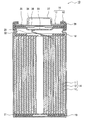
- FIG. 1 is a vertical cross-sectional view of a secondary battery that is an example of an embodiment.
- FIG. 3 is a cross-sectional view of a surface portion on one side of a positive electrode that is an example of an embodiment. It is a figure corresponding to FIG. 2 in the conventional positive electrode. 3 is an electron micrograph of the interface between the positive electrode current collector and the protective layer of the positive electrode, which is an example of the embodiment, observed from the positive electrode current collector side.
- 5 is an image corresponding to FIG. 4 in a conventional positive electrode.
- 5 is an image corresponding to FIG. 4 in the positive electrodes of Examples 1 and 2 and Comparative Example 1.
- a wound type electrode body is illustrated as a cylindrical battery housed in a cylindrical battery case, but the electrode body is not limited to the wound type, and a plurality of positive electrodes and a plurality of negative electrodes form separators. It may be a laminated type in which one sheet is alternately laminated with the sheet interposed therebetween.
- the secondary battery according to the present disclosure may be a prismatic battery having a prismatic metal case, a coin battery having a coin-shaped metal case, or the like, and is composed of a laminate sheet including a metal layer and a resin layer. It may be a laminated battery provided with the outer casing.
- FIG. 1 is a sectional view of a secondary battery 10 which is an example of the embodiment.
- the secondary battery 10 includes an electrode body 14, an electrolyte, and a battery case 15 that houses the electrode body 14 and the electrolyte.
- the electrode body 14 includes a positive electrode 11, a negative electrode 12, and a separator 13, and has a winding structure in which the positive electrode 11 and the negative electrode 12 are wound via the separator 13.
- the battery case 15 is composed of a bottomed cylindrical outer can 16 and a sealing body 17 that closes the opening of the outer can 16.
- the secondary battery 10 may be a secondary battery using an aqueous electrolyte or a non-aqueous electrolyte.
- the secondary battery 10 will be described as a non-aqueous electrolyte secondary battery such as a lithium ion battery using a non-aqueous electrolyte.
- the non-aqueous electrolyte contains a non-aqueous solvent and an electrolyte salt dissolved in the non-aqueous solvent.
- the non-aqueous solvent for example, esters, ethers, nitriles, amides, and a mixed solvent of two or more kinds of these may be used.
- the non-aqueous solvent may contain a halogen-substituted product obtained by substituting at least part of hydrogen in these solvents with a halogen atom such as fluorine.
- the non-aqueous electrolyte is not limited to the liquid electrolyte and may be a solid electrolyte.
- the electrolyte salt for example, a lithium salt such as LiPF 6 is used.
- the secondary battery 10 includes insulating plates 18 and 19 arranged above and below the electrode body 14, respectively.
- the positive electrode lead 20 attached to the positive electrode 11 extends to the sealing body 17 side through the through hole of the insulating plate 18, and the negative electrode lead 21 attached to the negative electrode 12 passes through the outside of the insulating plate 19. And extends to the bottom side of the outer can 16.
- the positive electrode lead 20 is connected to the lower surface of the bottom plate 23 of the sealing body 17 by welding or the like, and the cap 27 which is the top plate of the sealing body 17 electrically connected to the bottom plate 23 serves as a positive electrode terminal.
- the negative electrode lead 21 is connected to the inner surface of the bottom of the outer can 16 by welding or the like, and the outer can 16 serves as a negative electrode terminal.
- the outer can 16 is, for example, a cylindrical metal container having a bottom.
- a gasket 28 is provided between the outer can 16 and the sealing body 17 to ensure the airtightness inside the battery.
- the outer can 16 is provided with a grooved portion 22 for supporting the sealing body 17, for example, a part of the side surface of the outer can 16 projects inward.
- the grooved portion 22 is preferably formed in an annular shape along the circumferential direction of the outer can 16, and the upper surface thereof supports the sealing body 17.
- the sealing body 17 has a structure in which a bottom plate 23, a lower valve body 24, an insulating member 25, an upper valve body 26, and a cap 27 are stacked in this order from the electrode body 14 side.
- Each member forming the sealing body 17 has, for example, a disc shape or a ring shape, and the respective members except the insulating member 25 are electrically connected to each other.
- the lower valve body 24 and the upper valve body 26 are connected to each other at their central portions, and an insulating member 25 is interposed between their peripheral portions.
- the positive electrode 11 forming the electrode body 14 will be described in detail.
- FIG. 2 is a cross-sectional view of one surface portion of the positive electrode 11 which is an example of the embodiment.
- the positive electrode 11 is provided between the positive electrode current collector 30, a positive electrode mixture layer 32 formed on at least one main surface of the positive electrode current collector 30, and the positive electrode current collector 30 and the positive electrode mixture layer 32.
- a protective layer 31 is formed from the viewpoint of increasing the capacity of the positive electrode.
- the positive electrode mixture layer 32 is preferably formed on both of the pair of main surfaces of the positive electrode current collector 30.
- the protective layer 31 is formed between the positive electrode current collector 30 and each positive electrode mixture layer 32.
- the positive electrode current collector 30 a foil of a metal such as aluminum or an aluminum alloy that is stable in the potential range of the positive electrode 11, a film in which the metal is arranged on the surface layer, and the like can be used.
- a preferable positive electrode current collector 30 is a metal foil made of aluminum or an aluminum alloy and has a thickness of 5 ⁇ m to 20 ⁇ m.
- the positive electrode mixture layer 32 includes a lithium-containing transition metal oxide 33 as a positive electrode active material, and a binder and a conductive material (not shown).
- the thickness of the positive electrode mixture layer 32 on one side of the positive electrode current collector 30 is, for example, 30 ⁇ m to 120 ⁇ m, preferably 50 ⁇ m to 90 ⁇ m.
- the lithium-containing transition metal oxide 33 contained in the positive electrode mixture layer 32 contains a transition metal element such as Co, Mn, and Ni.
- a transition metal element such as Co, Mn, and Ni.
- Examples of the lithium-containing transition metal oxide 33 include Li x CoO 2 , Li x NiO 2 , Li x MnO 2 , Li x Co y Ni 1-y O 2 , Li x Co y M 1-y O z , Li.
- the average particle size of the lithium-containing transition metal oxide 33 is preferably 5 ⁇ m to 20 ⁇ m, more preferably 7 ⁇ m to 15 ⁇ m.
- the average particle diameter of the lithium-containing transition metal oxide 33 in the present disclosure is a volume average particle diameter measured by a laser diffraction method, and means a median diameter (D50) at which the volume integrated value is 50% in the particle diameter distribution. To do.
- the average particle size of the lithium-containing transition metal oxide 33 can be measured using, for example, a laser diffraction/scattering particle size distribution measuring device (manufactured by Horiba, Ltd.).
- a fluororesin such as polytetrafluoroethylene (PTFE) and polyvinylidene fluoride (PVdF), polyacrylonitrile (PAN), a polyimide resin, an acrylic resin, a polyolefin resin Resin etc.
- these resins may be used in combination with a cellulose derivative such as carboxymethyl cellulose (CMC) or a salt thereof, polyethylene oxide (PEO) and the like.
- the content of the binder in the positive electrode mixture layer 32 is preferably 0.1% by mass to 10% by mass, more preferably 0.5% by mass to 5% by mass, based on the total mass of the positive electrode mixture layer 32.
- Examples of the conductive material contained in the positive electrode mixture layer 32 include carbon materials such as carbon black (CB), acetylene black (AB), Ketjen black, and graphite. These may be used alone or in combination of two or more.
- the content of the conductive material in the positive electrode mixture layer 32 is preferably 0.1% by mass to 10% by mass and more preferably 0.5% by mass to 5% by mass with respect to the total mass of the positive electrode mixture layer 32.
- the protective layer 31 is formed between the positive electrode current collector 30 and the positive electrode mixture layer 32.
- the protective layer 31 separates the lithium-containing transition metal oxide 33 from the positive electrode current collector 30 containing aluminum as a main component. When an internal short circuit or the like occurs, the protective layer 31 suppresses the redox reaction between the positive electrode current collector 30 and the lithium-containing transition metal oxide 33, so the safety of the secondary battery 10 is improved.
- the protective layer 31 includes an inorganic compound having a lower oxidizing power than the lithium-containing transition metal oxide 33 (hereinafter referred to as “inorganic compound P”), a conductive material, and a binder.
- the inorganic compound P is the main component of the protective layer 31 and has an effect of suppressing heat generation when an abnormality such as an internal short circuit occurs.
- the conductive material suppresses an increase in resistance due to the provision of the protective layer 31.
- the binder secures the mechanical strength of the protective layer 31 by binding the inorganic compound P and the conductive material, and enhances the binding between the protective layer 31, the positive electrode current collector 30 and the positive electrode mixture layer 32 for protection. Prevent peeling of layers.
- the inorganic compound P is a particle having an average particle size of 1 ⁇ m or less.
- the average particle size of the inorganic compound P is, similarly to the average particle size of the lithium-containing transition metal oxide 33, a volume average particle size measured by a laser diffraction method, and a volume integrated value in a particle size distribution. Means a median diameter (D50) of 50%.
- suitable inorganic compounds P include inorganic oxides such as manganese oxide, silicon dioxide, titanium dioxide, and aluminum oxide, and it is preferable to use aluminum oxide, which has high chemical stability and is inexpensive.
- the content of the inorganic compound P in the protective layer 31 is preferably 70% by mass to 99.8% by mass, and particularly preferably 90% by mass to 99% by mass, based on the total mass of the protective layer 31.
- the content of the inorganic compound P is within the range, the effect of suppressing the redox reaction is improved, and the amount of heat generated when an abnormality such as an internal short circuit occurs can be easily reduced.
- the conductive material contained in the protective layer 31 is the same as the conductive material applied to the positive electrode mixture layer 32, for example, carbon materials such as carbon black (CB), acetylene black (AB), Ketjen black and graphite. Can be used. These may be used alone or in combination of two or more.
- the content of the conductive material is preferably 0.1% by weight to 20% by weight, and particularly preferably 1% by weight to 10% by weight, based on the total weight of the protective layer 31. From the viewpoint of ensuring current collection, the content of the conductive material in the protective layer 31 is preferably higher than the content of the conductive material in the positive electrode mixture layer 32, for example.
- the binder contained in the protective layer 31 is the same as the conductive material applied to the positive electrode mixture layer 32, for example, a fluororesin such as polytetrafluoroethylene (PTFE) or polyvinylidene fluoride (PVdF), or a polyresin.
- a fluororesin such as polytetrafluoroethylene (PTFE) or polyvinylidene fluoride (PVdF)
- PVdF polyvinylidene fluoride
- PAN Acrylonitrile
- a polyimide resin an acrylic resin
- a polyolefin resin or the like
- the content of the binder is preferably 0.1% by weight to 20% by weight, and particularly preferably 1% by weight to 10% by weight, based on the total weight of the protective layer 31.
- the lithium-containing transition metal oxide 33 contained in the positive electrode mixture layer 32 penetrates a part of the protective layer 31 and is in contact with the positive electrode current collector 30.
- the coverage ⁇ means the ratio of the protective layer 31 covering the main surface of the positive electrode current collector 30, and the value obtained by dividing the area of the hole by the area of the main surface of the positive electrode current collector 30 is subtracted from 100%.
- the coverage ⁇ is 50% or more, preferably 70% or more, and more preferably 85% or more.
- the upper limit value of the coverage rate ⁇ is preferably 99%, more preferably 97%, particularly preferably 95%.
- the coverage ⁇ of the protective layer 31 can be obtained from an electron micrograph (hereinafter, also referred to as “SEM photograph”) of a cross section of the interface between the positive electrode current collector 30 and the protective layer 31. At the interface, the coverage can be calculated by dividing the total length of the protective layer 31 covering the positive electrode current collector 30 by the observed length of the interface.
- the coverage is obtained from the cross section of the interface between the positive electrode current collector 30 and the protective layer 31, and when obtaining the coverage ⁇ from the coverage, the coverage of a considerable number of cross sections is calculated by
- the coverage ratio ⁇ can be calculated in consideration of the obtained mode values of the coverage ratios and the like.
- the coverage ⁇ is, for example, 70% or more, preferably 85% or more.
- the surface density of the protective layer 31 can be 3 g/m 2 to 12 g/m 2 .
- the surface density of the protective layer 31 is preferably the above value.
- the surface density of the protective layer 31 can be adjusted by the average particle diameter of the inorganic compound P and the like. Within this range, the higher the surface density, the higher the safety of the secondary battery 10.
- the thickness of the protective layer 31 can be set to 1 ⁇ m to 5 ⁇ m. The higher the areal density, the thinner the protective layer 31 can be made, and the smaller the resistivity of the protective layer can be made.
- FIG. 3 is a diagram corresponding to FIG. 2 in the conventional positive electrode.
- the lithium-containing transition metal oxide 33 does not penetrate the protective layer 31, and the lithium-containing transition metal oxide 33 does not contact the positive electrode current collector 30. Therefore, even when an abnormal situation such as an internal short circuit occurs, it is possible to suppress the occurrence of a redox reaction between the lithium-containing transition metal oxide 33 and the positive electrode current collector 30, and the safety of the secondary battery 10 is improved. Nature is secured. However, since the resistance of the positive electrode 11 is large, it is difficult to increase the input/output characteristics of the secondary battery 10.
- the positive electrode 11 can be produced, for example, by forming the protective layer 31 and the positive electrode mixture layer 32 in this order on the main surface of the positive electrode current collector 30, and then compressing them using a roller.
- the protective layer 31 can be formed by applying a protective slurry containing an inorganic compound P, a conductive material, and a binder to the main surface of the positive electrode current collector 30 and drying the coating film.
- the positive electrode mixture layer 32 can be formed by applying a positive electrode mixture slurry containing a lithium-containing transition metal oxide 33, a conductive material, and a binder to the surface of the protective layer 31 and drying the coating film.
- the protective layer 31 and the positive electrode mixture layer 32 may be laminated and then dried.
- the ratio of the lithium-containing transition metal oxide 33 penetrating the protective layer 31, that is, the coverage ⁇ and The coverage ⁇ can be changed.
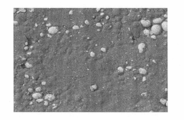
- FIG. 4 is an SEM photograph of the interface between the positive electrode current collector 30 and the protective layer 31 of the positive electrode, which is an example of the embodiment, observed at a magnification of 500 times from the positive electrode current collector side, and FIG. It is a figure corresponding to.
- the white part is the lithium-containing transition metal oxide 33
- the black part is the protective layer 31.
- the positive electrode current collector 30 is covered with the protective layer 31 only with the black portion and without the white portion.
- a laminate sample for observing the interface between the positive electrode current collector 30 and the protective layer 31 from the positive electrode current collector side can be prepared as follows. (1) After preparing a 10% NaOH aqueous solution, cool it to room temperature. (2) 10% NaOH aqueous solution is put into a petri dish to immerse the positive electrode 11. (3) The amount of bubbles generated increases 10 to 30 minutes after the positive electrode 11 is immersed in the 10% NaOH aqueous solution, and the laminate sample of the protective layer 31 and the positive electrode mixture layer 32 is peeled from the positive electrode current collector 30. (4) The peeled laminate sample is washed with pure water. (5) The laminate sample is placed on a petri dish lined with filter paper and dried under reduced pressure for 2 hours.
- the coverage ⁇ can be calculated as follows. (1) The interface between the protective layer 31 and the lithium-containing transition metal oxide 33 is binarized by using an image software for particle analysis with respect to an SEM photograph of the vicinity of the center of the laminated body sample at a constant magnification. Clarify. (2) The size and area of the lithium-containing transition metal oxide 33 are measured using the above-mentioned image software. (3) The ratio of the area of the lithium-containing transition metal oxide 33 measured in (2) to the total area of the region analyzed by the above image software is calculated, and the value is subtracted from 100% to obtain the positive electrode current collector. The coverage ⁇ of the protective layer 31 on the principal surface 30 is calculated.
- the size of the portion where the lithium-containing transition metal oxide 33 is in contact with the positive electrode current collector 30 is preferably 50 ⁇ m or less.
- the size of the portion where the lithium-containing transition metal oxide 33 is in contact with the positive electrode current collector 30 may be the size of the lithium-containing transition metal oxide 33 measured in (2) of the method of calculating the coverage ⁇ described above. it can.
- the size of 50 ⁇ m or less means that the size is within a square having one side of 50 ⁇ m.
- the size and area of the portion where the lithium-containing transition metal oxide 33 is in contact with the positive electrode current collector 30 means the size and area of the pores due to the lithium-containing transition metal oxide 33 penetrating a part of the protective layer 31 and Synonymous with area.
- the lithium-containing transition metal oxide 33 is exposed from the hole, and the lithium-containing transition metal oxide 33 is in contact with the positive electrode current collector 30.
- the conductive material contained in the positive electrode mixture layer 32 may also be exposed from the hole. In particular, in a hole where a plurality of lithium-containing transition metal oxides 33 are exposed, the conductive material may be present at the interface between the lithium-containing transition metal oxides 33.
- the negative electrode 12 includes a negative electrode current collector and a negative electrode mixture layer formed on at least one surface of the negative electrode current collector.
- a metal foil such as copper or a copper alloy, which is stable in the potential range of the negative electrode 12, a film in which the metal is disposed on the surface layer, and the like can be used.
- the negative electrode mixture layer contains a negative electrode active material and a binder, and is preferably formed on both surfaces of the negative electrode current collector.
- the negative electrode 12 is obtained by applying a negative electrode mixture slurry containing a negative electrode active material, a binder and the like on the surface of the negative electrode current collector, drying the coating film, and then compressing the negative electrode mixture material layer of the negative electrode current collector. It can be manufactured by forming on both sides.
- the negative electrode active material is not particularly limited as long as it can reversibly store and release lithium ions, and generally a carbon material such as graphite is used.
- the graphite may be any of natural graphite such as scaly graphite, lump graphite, and earth graphite, lump artificial graphite, and artificial graphite such as graphitized mesophase carbon microbeads.
- a metal alloying with Li such as Si or Sn, a metal compound containing Si or Sn, or a lithium titanium composite oxide may be used as the negative electrode active material.
- a Si-containing compound represented by SiO x (0.5 ⁇ x ⁇ 1.6) may be used in combination with a carbon material such as graphite.
- the binder contained in the negative electrode mixture layer may be a fluorine-containing resin such as PTFE or PVdF, PAN, polyimide, an acrylic resin, or polyolefin as in the case of the positive electrode 11, but is preferably styrene. -Butadiene rubber (SBR) is used.
- the negative electrode mixture layer may contain carboxymethyl cellulose (CMC) or a salt thereof, polyacrylic acid (PAA) or a salt thereof, PVA, or the like.
- the negative electrode mixture layer contains, for example, SBR and CMC or a salt thereof.
- a porous sheet having ion permeability and insulation is used as the separator 13.
- the porous sheet include a microporous thin film, woven fabric, non-woven fabric and the like.
- Suitable materials for the separator are polyolefins such as polyethylene and polypropylene, and cellulose.
- the separator 13 may have a single-layer structure or a laminated structure. Further, on the surface of the separator 13, a resin layer having high heat resistance such as aramid resin or a filler layer containing a filler of an inorganic compound may be provided.
- Example 1 [Preparation of positive electrode] Aluminum oxide, acetylene black (AB), and polyvinylidene fluoride (PVdF) were mixed at a solid content mass ratio of 93.5:5:1.5, and the dispersion medium was N-methyl-2-pyrrolidone (NMP).
- NMP N-methyl-2-pyrrolidone
- LiNi 0.5 Co 0.2 Mn 0.3 O 2 was used as the lithium-containing transition metal oxide. LiNi 0.5 Co 0.2 Mn 0.3 O 2 , acetylene black (AB), and polyvinylidene fluoride (PVdF) were mixed at a solid content mass ratio of 97:2:1, and the dispersion medium was N-. A positive electrode mixture slurry containing methyl-2-pyrrolidone (NMP) was prepared. The positive electrode mixture slurry was applied to the surface of the protective layer to form a positive electrode mixture layer. Next, rolling was performed using a roller having a diameter of 40 cm. The linear pressure indicating the pressure during rolling by the roller was set to 3500 kgf/cm. This was cut into a predetermined electrode size to prepare a positive electrode in which a protective layer and a positive electrode mixture layer were sequentially formed on both surfaces of a positive electrode current collector. The coverage ⁇ was measured by using the cut edge portion when the electrode size was cut.
- Graphite powder, carboxymethyl cellulose (CMC), and a dispersion of styrene-butadiene rubber (SBR) are mixed at a solid content mass ratio of 98.7:0.7:0.6, and the dispersion medium is water.
- a negative electrode mixture slurry was prepared.
- the negative electrode mixture slurry was applied on both sides of a negative electrode current collector made of copper foil, and then compressed using rollers to form negative electrode mixture layers on both sides of the negative electrode current collector.
- the negative electrode current collector was cut into a predetermined electrode size to prepare a negative electrode.
- Ethylene carbonate (EC), methyl ethyl carbonate (EMC), and dimethyl carbonate (DMC) were mixed in a volume ratio of 3:3:4.
- LiPF 6 was dissolved in the mixed solvent to a concentration of 1.2 mol/L to prepare a non-aqueous electrolyte.
- a tab was attached to each of the positive electrode and the negative electrode, and the positive electrode and the negative electrode were spirally wound with a polyethylene separator interposed therebetween to manufacture a spirally wound electrode body.
- the electrode body was housed in a bottomed cylindrical outer can having an outer diameter of 18.2 mm and a height of 65 mm, the above non-aqueous electrolyte was injected, and then the opening of the outer can was sealed with a gasket and a sealing body, 18650.
- Type cylindrical non-aqueous electrolyte secondary battery A1 was produced.
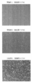
- FIG. 6 is an SEM photograph in which the interfaces between the positive electrode current collectors of Examples 1 and 2 and Comparative Example 1 and the protective layer were observed from the positive electrode current collector side at a magnification of 70 times.
- each of the secondary batteries of Examples 1 to 5 has a lower heat generation temperature than the secondary batteries of Comparative Examples 1 and 2 and the secondary battery of Comparative Example 3. Since the resistivity of the positive electrode is lower than that of the positive electrode, it can be confirmed that the secondary battery has safety and high battery performance.
Abstract
This positive electrode is characterized by comprising a positive electrode collector, a positive electrode mixture layer that contains a lithium-containing transition metal oxide, and a protective layer that is arranged between the positive electrode collector and the positive electrode mixture layer, and is also characterized in that: the protective layer contains an inorganic compound that has a lower oxidative power than the lithium-containing transition metal oxide; a part of the lithium-containing transition metal oxide penetrates through the protective layer so as to be in contact with the positive electrode collector; and the coverage α of the main surface of the positive electrode collector by the protective layer is 50% or more.
Description
本開示は、正極及び二次電池に関する。
The present disclosure relates to a positive electrode and a secondary battery.
二次電池において、電池の内部短絡が発生した場合、又は電池が高温に曝された場合に正極活物質として含まれるリチウム含有遷移金属酸化物と正極集電体が酸化還元反応し、大きな発熱が生じるおそれがある。特許文献1は、リチウム含有遷移金属酸化物と正極集電体との酸化還元反応を抑制するために、リチウム含有遷移金属酸化物を含む正極合材層と正極集電体との間に両者を隔離するための保護層を形成した二次電池を開示している。
In a secondary battery, when an internal short circuit occurs in the battery or when the battery is exposed to a high temperature, the lithium-containing transition metal oxide contained as the positive electrode active material and the positive electrode current collector undergo an oxidation-reduction reaction, resulting in large heat generation. May occur. Patent Document 1 discloses that a lithium-containing transition metal oxide and a positive electrode current collector are provided between the positive electrode mixture layer containing the lithium-containing transition metal oxide and the positive electrode current collector in order to suppress the redox reaction between the lithium-containing transition metal oxide and the positive electrode current collector. A secondary battery having a protective layer for isolation is disclosed.
しかし、保護層を設けることによって電池の内部抵抗が大きくなるため、特許文献1に開示された技術は、安全性と電池性能との両立という面では未だ改良の余地がある。
However, since the internal resistance of the battery is increased by providing the protective layer, the technology disclosed in Patent Document 1 still has room for improvement in terms of both safety and battery performance.
よって、本開示の目的は、保護層によって安全性を確保しつつ、電池性能を高めた二次電池を提供することである。
Therefore, an object of the present disclosure is to provide a secondary battery having improved battery performance while ensuring safety with a protective layer.
本開示の一態様である正極は、正極集電体と、リチウム含有遷移金属酸化物を含む正極合材層と、正極集電体と正極合材層との間に設けられた保護層とを備え、保護層は、リチウム含有遷移金属酸化物よりも酸化力が低い無機化合物を含み、リチウム含有遷移金属酸化物の一部は、保護層を貫通して正極集電体に接し、正極集電体の主面に対する保護層の被覆率αは50%以上であることを特徴とする。
A positive electrode which is one embodiment of the present disclosure includes a positive electrode current collector, a positive electrode mixture layer containing a lithium-containing transition metal oxide, and a protective layer provided between the positive electrode current collector and the positive electrode mixture layer. The protective layer includes an inorganic compound having an oxidizing power lower than that of the lithium-containing transition metal oxide, and a part of the lithium-containing transition metal oxide penetrates the protective layer and contacts the positive electrode current collector, The coverage α of the protective layer on the main surface of the body is 50% or more.
本開示の一態様である二次電池は、上記正極と、負極と、電解質とを備えることを特徴とする。
A secondary battery according to one aspect of the present disclosure is characterized by including the positive electrode, the negative electrode, and an electrolyte.
本開示の一態様によれば、高い安全性と高い電池性能とを有する二次電池を提供することができる。
According to one aspect of the present disclosure, a secondary battery having high safety and high battery performance can be provided.
以下、図面を参照しながら、本開示に係る二次電池の実施形態の一例について詳説する。また、以下では、巻回型の電極体が円筒形の電池ケースに収容された円筒形電池を例示するが、電極体は巻回型に限定されず、複数の正極と複数の負極がセパレータを介して1枚ずつ交互に積層されてなる積層型であってもよい。また、本開示に係る二次電池は、角形の金属製ケースを備える角形電池、コイン形の金属製ケースを備えるコイン形電池等であってもよく、金属層及び樹脂層を含むラミネートシートで構成された外装体を備えるラミネート電池であってもよい。
Hereinafter, an example of an embodiment of a secondary battery according to the present disclosure will be described in detail with reference to the drawings. Further, in the following, a wound type electrode body is illustrated as a cylindrical battery housed in a cylindrical battery case, but the electrode body is not limited to the wound type, and a plurality of positive electrodes and a plurality of negative electrodes form separators. It may be a laminated type in which one sheet is alternately laminated with the sheet interposed therebetween. Further, the secondary battery according to the present disclosure may be a prismatic battery having a prismatic metal case, a coin battery having a coin-shaped metal case, or the like, and is composed of a laminate sheet including a metal layer and a resin layer. It may be a laminated battery provided with the outer casing.
図1は、実施形態の一例である二次電池10の断面図である。図1に例示するように、二次電池10は、電極体14と、電解質と、電極体14及び電解質を収容する電池ケース15とを備える。電極体14は、正極11と、負極12と、セパレータ13とを備え、正極11と負極12がセパレータ13を介して巻回された巻回構造を有する。電池ケース15は、有底円筒形状の外装缶16と、外装缶16の開口部を塞ぐ封口体17とで構成されている。なお、二次電池10は、水系電解質を用いた二次電池であってもよく、非水電解質を用いた二次電池であってもよい。以下では、二次電池10は、非水電解質を用いたリチウムイオン電池等の非水電解質二次電池として説明する。
FIG. 1 is a sectional view of a secondary battery 10 which is an example of the embodiment. As illustrated in FIG. 1, the secondary battery 10 includes an electrode body 14, an electrolyte, and a battery case 15 that houses the electrode body 14 and the electrolyte. The electrode body 14 includes a positive electrode 11, a negative electrode 12, and a separator 13, and has a winding structure in which the positive electrode 11 and the negative electrode 12 are wound via the separator 13. The battery case 15 is composed of a bottomed cylindrical outer can 16 and a sealing body 17 that closes the opening of the outer can 16. The secondary battery 10 may be a secondary battery using an aqueous electrolyte or a non-aqueous electrolyte. Hereinafter, the secondary battery 10 will be described as a non-aqueous electrolyte secondary battery such as a lithium ion battery using a non-aqueous electrolyte.
非水電解質は、非水溶媒と、非水溶媒に溶解した電解質塩とを含む。非水溶媒には、例えばエステル類、エーテル類、ニトリル類、アミド類、及びこれらの2種以上の混合溶媒等を用いてもよい。非水溶媒は、これら溶媒の水素の少なくとも一部をフッ素等のハロゲン原子で置換したハロゲン置換体を含有していてもよい。なお、非水電解質は液体電解質に限定されず、固体電解質であってもよい。電解質塩には、例えばLiPF6等のリチウム塩が使用される。
The non-aqueous electrolyte contains a non-aqueous solvent and an electrolyte salt dissolved in the non-aqueous solvent. As the non-aqueous solvent, for example, esters, ethers, nitriles, amides, and a mixed solvent of two or more kinds of these may be used. The non-aqueous solvent may contain a halogen-substituted product obtained by substituting at least part of hydrogen in these solvents with a halogen atom such as fluorine. The non-aqueous electrolyte is not limited to the liquid electrolyte and may be a solid electrolyte. As the electrolyte salt, for example, a lithium salt such as LiPF 6 is used.
二次電池10は、電極体14の上下にそれぞれ配置された絶縁板18,19を備える。図1に示す例では、正極11に取り付けられた正極リード20が絶縁板18の貫通孔を通って封口体17側に延び、負極12に取り付けられた負極リード21が絶縁板19の外側を通って外装缶16の底部側に延びている。正極リード20は封口体17の底板23の下面に溶接等で接続され、底板23と電気的に接続された封口体17の天板であるキャップ27が正極端子となる。負極リード21は外装缶16の底部内面に溶接等で接続され、外装缶16が負極端子となる。
The secondary battery 10 includes insulating plates 18 and 19 arranged above and below the electrode body 14, respectively. In the example shown in FIG. 1, the positive electrode lead 20 attached to the positive electrode 11 extends to the sealing body 17 side through the through hole of the insulating plate 18, and the negative electrode lead 21 attached to the negative electrode 12 passes through the outside of the insulating plate 19. And extends to the bottom side of the outer can 16. The positive electrode lead 20 is connected to the lower surface of the bottom plate 23 of the sealing body 17 by welding or the like, and the cap 27 which is the top plate of the sealing body 17 electrically connected to the bottom plate 23 serves as a positive electrode terminal. The negative electrode lead 21 is connected to the inner surface of the bottom of the outer can 16 by welding or the like, and the outer can 16 serves as a negative electrode terminal.
外装缶16は、例えば有底円筒形状の金属製容器である。外装缶16と封口体17との間にはガスケット28が設けられ、電池内部の密閉性が確保されている。外装缶16には、例えば側面部の一部が内側に張り出した、封口体17を支持する溝入部22が形成されている。溝入部22は、外装缶16の周方向に沿って環状に形成されることが好ましく、その上面で封口体17を支持する。
The outer can 16 is, for example, a cylindrical metal container having a bottom. A gasket 28 is provided between the outer can 16 and the sealing body 17 to ensure the airtightness inside the battery. The outer can 16 is provided with a grooved portion 22 for supporting the sealing body 17, for example, a part of the side surface of the outer can 16 projects inward. The grooved portion 22 is preferably formed in an annular shape along the circumferential direction of the outer can 16, and the upper surface thereof supports the sealing body 17.
封口体17は、電極体14側から順に、底板23、下弁体24、絶縁部材25、上弁体26、及びキャップ27が積層された構造を有する。封口体17を構成する各部材は、例えば円板形状又はリング形状を有し、絶縁部材25を除く各部材は互いに電気的に接続されている。下弁体24と上弁体26は各々の中央部で互いに接続され、各々の周縁部の間には絶縁部材25が介在している。異常発熱で電池の内圧が上昇すると、下弁体24が上弁体26をキャップ27側に押し上げるように変形して破断し、下弁体24と上弁体26の間の電流経路が遮断される。さらに内圧が上昇すると、上弁体26が破断し、キャップ27の開口部からガスが排出される。
The sealing body 17 has a structure in which a bottom plate 23, a lower valve body 24, an insulating member 25, an upper valve body 26, and a cap 27 are stacked in this order from the electrode body 14 side. Each member forming the sealing body 17 has, for example, a disc shape or a ring shape, and the respective members except the insulating member 25 are electrically connected to each other. The lower valve body 24 and the upper valve body 26 are connected to each other at their central portions, and an insulating member 25 is interposed between their peripheral portions. When the internal pressure of the battery rises due to abnormal heat generation, the lower valve body 24 is deformed and ruptured so as to push the upper valve body 26 toward the cap 27 side, and the current path between the lower valve body 24 and the upper valve body 26 is cut off. It When the internal pressure further rises, the upper valve body 26 breaks and gas is discharged from the opening of the cap 27.
以下、電極体14を構成する正極11について詳説する。
Hereinafter, the positive electrode 11 forming the electrode body 14 will be described in detail.
[正極]
図2は、実施形態の一例である正極11の片側表面部分の断面図である。正極11は、正極集電体30と、正極集電体30の少なくとも一方の主面に形成された正極合材層32と、正極集電体30と正極合材層32との間に設けられた保護層31とを備える。正極合材層32は、正極の高容量化の観点から、正極集電体30の一対の主面の両方に形成されることが好ましい。保護層31は、正極集電体30と各正極合材層32との間にそれぞれ形成される。 [Positive electrode]
FIG. 2 is a cross-sectional view of one surface portion of thepositive electrode 11 which is an example of the embodiment. The positive electrode 11 is provided between the positive electrode current collector 30, a positive electrode mixture layer 32 formed on at least one main surface of the positive electrode current collector 30, and the positive electrode current collector 30 and the positive electrode mixture layer 32. And a protective layer 31. From the viewpoint of increasing the capacity of the positive electrode, the positive electrode mixture layer 32 is preferably formed on both of the pair of main surfaces of the positive electrode current collector 30. The protective layer 31 is formed between the positive electrode current collector 30 and each positive electrode mixture layer 32.
図2は、実施形態の一例である正極11の片側表面部分の断面図である。正極11は、正極集電体30と、正極集電体30の少なくとも一方の主面に形成された正極合材層32と、正極集電体30と正極合材層32との間に設けられた保護層31とを備える。正極合材層32は、正極の高容量化の観点から、正極集電体30の一対の主面の両方に形成されることが好ましい。保護層31は、正極集電体30と各正極合材層32との間にそれぞれ形成される。 [Positive electrode]
FIG. 2 is a cross-sectional view of one surface portion of the
正極集電体30には、アルミニウム、又はアルミニウム合金等の正極11の電位範囲で安定な金属の箔、当該金属を表層に配置したフィルムなどを用いることができる。好適な正極集電体30は、アルミニウム又はアルミニウム合金からなる金属の箔であって、5μm~20μmの厚みを有する。正極合材層32は、正極活物質としてのリチウム含有遷移金属酸化物33と、図示しない結着材及び導電材とを含む。正極合材層32の厚みは、正極集電体30の片側で、例えば30μm~120μmであり、好ましくは50μm~90μmである。
As the positive electrode current collector 30, a foil of a metal such as aluminum or an aluminum alloy that is stable in the potential range of the positive electrode 11, a film in which the metal is arranged on the surface layer, and the like can be used. A preferable positive electrode current collector 30 is a metal foil made of aluminum or an aluminum alloy and has a thickness of 5 μm to 20 μm. The positive electrode mixture layer 32 includes a lithium-containing transition metal oxide 33 as a positive electrode active material, and a binder and a conductive material (not shown). The thickness of the positive electrode mixture layer 32 on one side of the positive electrode current collector 30 is, for example, 30 μm to 120 μm, preferably 50 μm to 90 μm.
正極合材層32に含まれるリチウム含有遷移金属酸化物33は、Co、Mn、Ni等の遷移金属元素を含有する。リチウム含有遷移金属酸化物33の例としては、LixCoO2、LixNiO2、LixMnO2、LixCoyNi1-yO2、LixCoyM1-yOz、LixNi1-yMyOz、LixMn2O4、LixMn2-yMyO4、LiMPO4、Li2MPO4F(M;Na、Mg、Sc、Y、Mn、Fe、Co、Ni、Cu、Zn、Al、Cr、Pb、Sb、Bのうち少なくとも1種、0<x≦1.2、0<y≦0.9、2.0≦z≦2.3)などが挙げられる。これらは、1種類を単独で用いてもよいし、複数種を混合して用いてもよい。リチウム含有遷移金属酸化物33の平均粒径は、好ましくは5μm~20μmであり、より好ましくは7μm~15μmである。本開示におけるリチウム含有遷移金属酸化物33の平均粒径は、レーザ回折法によって測定される体積平均粒径であって、粒子径分布において体積積算値が50%となるメジアン径(D50)を意味する。リチウム含有遷移金属酸化物33の平均粒径は、例えば、レーザ回折散乱式粒度分布測定装置(株式会社堀場製作所製)を用いて測定できる。
The lithium-containing transition metal oxide 33 contained in the positive electrode mixture layer 32 contains a transition metal element such as Co, Mn, and Ni. Examples of the lithium-containing transition metal oxide 33 include Li x CoO 2 , Li x NiO 2 , Li x MnO 2 , Li x Co y Ni 1-y O 2 , Li x Co y M 1-y O z , Li. x Ni 1-y M y O z , Li x Mn 2 O 4 , Li x Mn 2- y My O 4 , LiMPO 4 , Li 2 MPO 4 F (M; Na, Mg, Sc, Y, Mn, Fe) , Co, Ni, Cu, Zn, Al, Cr, Pb, Sb, B, at least one kind, 0<x≦1.2, 0<y≦0.9, 2.0≦z≦2.3) And so on. These may be used alone or in combination of two or more. The average particle size of the lithium-containing transition metal oxide 33 is preferably 5 μm to 20 μm, more preferably 7 μm to 15 μm. The average particle diameter of the lithium-containing transition metal oxide 33 in the present disclosure is a volume average particle diameter measured by a laser diffraction method, and means a median diameter (D50) at which the volume integrated value is 50% in the particle diameter distribution. To do. The average particle size of the lithium-containing transition metal oxide 33 can be measured using, for example, a laser diffraction/scattering particle size distribution measuring device (manufactured by Horiba, Ltd.).
正極合材層32に含まれる結着材としては、ポリテトラフルオロエチレン(PTFE)、ポリフッ化ビニリデン(PVdF)等のフッ素系樹脂、ポリアクリロニトリル(PAN)、ポリイミド系樹脂、アクリル系樹脂、ポリオレフィン系樹脂などが例示できる。また、これらの樹脂と、カルボキシメチルセルロース(CMC)又はその塩等のセルロース誘導体、ポリエチレンオキシド(PEO)などが併用されてもよい。正極合材層32における結着材の含有量は、正極合材層32の総質量に対して0.1質量%~10質量%が好ましく、0.5質量%~5質量%がより好ましい。
As the binder contained in the positive electrode mixture layer 32, a fluororesin such as polytetrafluoroethylene (PTFE) and polyvinylidene fluoride (PVdF), polyacrylonitrile (PAN), a polyimide resin, an acrylic resin, a polyolefin resin Resin etc. can be illustrated. Further, these resins may be used in combination with a cellulose derivative such as carboxymethyl cellulose (CMC) or a salt thereof, polyethylene oxide (PEO) and the like. The content of the binder in the positive electrode mixture layer 32 is preferably 0.1% by mass to 10% by mass, more preferably 0.5% by mass to 5% by mass, based on the total mass of the positive electrode mixture layer 32.
正極合材層32に含まれる導電材としては、カーボンブラック(CB)、アセチレンブラック(AB)、ケッチェンブラック、黒鉛等の炭素材料などが例示できる。これらは、1種類を単独で用いてもよく、複数種を混合して用いてもよい。正極合材層32における導電材の含有量は、正極合材層32の総質量に対して0.1質量%~10質量%が好ましく、0.5質量%~5質量%がより好ましい。
Examples of the conductive material contained in the positive electrode mixture layer 32 include carbon materials such as carbon black (CB), acetylene black (AB), Ketjen black, and graphite. These may be used alone or in combination of two or more. The content of the conductive material in the positive electrode mixture layer 32 is preferably 0.1% by mass to 10% by mass and more preferably 0.5% by mass to 5% by mass with respect to the total mass of the positive electrode mixture layer 32.
保護層31は、正極集電体30と正極合材層32との間に形成される。保護層31は、アルミニウムを主成分とする正極集電体30からリチウム含有遷移金属酸化物33を隔離する。内部短絡等が発生した場合において、保護層31が、正極集電体30とリチウム含有遷移金属酸化物33との間の酸化還元反応を抑制するので、二次電池10の安全性が向上する。
The protective layer 31 is formed between the positive electrode current collector 30 and the positive electrode mixture layer 32. The protective layer 31 separates the lithium-containing transition metal oxide 33 from the positive electrode current collector 30 containing aluminum as a main component. When an internal short circuit or the like occurs, the protective layer 31 suppresses the redox reaction between the positive electrode current collector 30 and the lithium-containing transition metal oxide 33, so the safety of the secondary battery 10 is improved.
保護層31は、リチウム含有遷移金属酸化物33よりも酸化力が低い無機化合物(以下、「無機化合物P」とする)、導電材、及び結着材を含む。無機化合物Pは、保護層31の主成分であって、内部短絡時等の異常が発生したときの発熱抑制効果が得られる。導電材は、保護層31を設けたことによる抵抗上昇を抑制する。結着材は、無機化合物Pと導電材を結着して保護層31の機械強度を確保すると共に保護層31と正極集電体30及び正極合材層32との結着を高めて、保護層の剥離を防止する。
The protective layer 31 includes an inorganic compound having a lower oxidizing power than the lithium-containing transition metal oxide 33 (hereinafter referred to as “inorganic compound P”), a conductive material, and a binder. The inorganic compound P is the main component of the protective layer 31 and has an effect of suppressing heat generation when an abnormality such as an internal short circuit occurs. The conductive material suppresses an increase in resistance due to the provision of the protective layer 31. The binder secures the mechanical strength of the protective layer 31 by binding the inorganic compound P and the conductive material, and enhances the binding between the protective layer 31, the positive electrode current collector 30 and the positive electrode mixture layer 32 for protection. Prevent peeling of layers.
無機化合物Pは、平均粒径が1μm以下の粒子である。ここで、無機化合物Pの平均粒径とは、リチウム含有遷移金属酸化物33の平均粒径と同様に、レーザ回折法によって測定される体積平均粒径であって、粒子径分布において体積積算値が50%となるメジアン径(D50)を意味する。好適な無機化合物Pとしては、酸化マンガン、二酸化珪素、二酸化チタン、酸化アルミニウム等の無機酸化物が例示できて、化学的安定性が高く、安価である酸化アルミニウムを用いることが好ましい。保護層31における無機化合物Pの含有量は、保護層31の総質量に対して70質量%~99.8質量%が好ましく、90質量%~99質量%が特に好ましい。無機化合物Pの含有量が当該範囲内であれば、酸化還元反応の抑制効果が向上し、内部短絡等の異常発生時の発熱量を低減し易くなる。
The inorganic compound P is a particle having an average particle size of 1 μm or less. Here, the average particle size of the inorganic compound P is, similarly to the average particle size of the lithium-containing transition metal oxide 33, a volume average particle size measured by a laser diffraction method, and a volume integrated value in a particle size distribution. Means a median diameter (D50) of 50%. Examples of suitable inorganic compounds P include inorganic oxides such as manganese oxide, silicon dioxide, titanium dioxide, and aluminum oxide, and it is preferable to use aluminum oxide, which has high chemical stability and is inexpensive. The content of the inorganic compound P in the protective layer 31 is preferably 70% by mass to 99.8% by mass, and particularly preferably 90% by mass to 99% by mass, based on the total mass of the protective layer 31. When the content of the inorganic compound P is within the range, the effect of suppressing the redox reaction is improved, and the amount of heat generated when an abnormality such as an internal short circuit occurs can be easily reduced.
保護層31に含まれる導電材には、正極合材層32に適用される導電材と同種のもの、例えばカーボンブラック(CB)、アセチレンブラック(AB)、ケッチェンブラック、黒鉛等の炭素材料などを用いることができる。これらは、単独で用いてもよく、2種類以上を組み合わせて用いてもよい。導電材の含有量は、保護層31の総重量に対して0.1重量%~20重量%が好ましく、1重量%~10重量%が特に好ましい。集電性確保の観点から保護層31における導電材の含有率は、例えば正極合材層32における導電材の含有率よりも高いことが好ましい。
The conductive material contained in the protective layer 31 is the same as the conductive material applied to the positive electrode mixture layer 32, for example, carbon materials such as carbon black (CB), acetylene black (AB), Ketjen black and graphite. Can be used. These may be used alone or in combination of two or more. The content of the conductive material is preferably 0.1% by weight to 20% by weight, and particularly preferably 1% by weight to 10% by weight, based on the total weight of the protective layer 31. From the viewpoint of ensuring current collection, the content of the conductive material in the protective layer 31 is preferably higher than the content of the conductive material in the positive electrode mixture layer 32, for example.
保護層31に含まれる結着材には、正極合材層32に適用される導電材と同種のもの、例えばポリテトラフルオロエチレン(PTFE)、ポリフッ化ビニリデン(PVdF)等のフッ素系樹脂、ポリアクリロニトリル(PAN)、ポリイミド系樹脂、アクリル系樹脂、ポリオレフィン系樹脂などを用いることができる。これらは、単独で用いてもよく、2種類以上を組み合わせて用いてもよい。結着材の含有量は、保護層31の総重量に対して0.1重量%~20重量%が好ましく、1重量%~10重量%が特に好ましい。
The binder contained in the protective layer 31 is the same as the conductive material applied to the positive electrode mixture layer 32, for example, a fluororesin such as polytetrafluoroethylene (PTFE) or polyvinylidene fluoride (PVdF), or a polyresin. Acrylonitrile (PAN), a polyimide resin, an acrylic resin, a polyolefin resin, or the like can be used. These may be used alone or in combination of two or more. The content of the binder is preferably 0.1% by weight to 20% by weight, and particularly preferably 1% by weight to 10% by weight, based on the total weight of the protective layer 31.
正極合材層32に含まれるリチウム含有遷移金属酸化物33は、保護層31の一部を貫通して正極集電体30と接している。正極集電体の主面上には、リチウム含有遷移金属酸化物33の一つの粒子が保護層31を貫通している部位や、リチウム含有遷移金属酸化物33の粒子が凝集して保護層31を貫通している部位が存在する。リチウム含有遷移金属酸化物33が保護層31の一部を貫通することで、二次電池10の内部抵抗を下げることができるので、電池性能を高くすることができる。また、正極集電体30の主面の50%以上は保護層31に覆われているため、内部短絡等が発生した際にも二次電池10の発熱は抑制される。
The lithium-containing transition metal oxide 33 contained in the positive electrode mixture layer 32 penetrates a part of the protective layer 31 and is in contact with the positive electrode current collector 30. On the main surface of the positive electrode current collector, a portion where one particle of the lithium-containing transition metal oxide 33 penetrates the protective layer 31, or a particle of the lithium-containing transition metal oxide 33 aggregates to form the protective layer 31. There is a part that penetrates. Since the lithium-containing transition metal oxide 33 penetrates a part of the protective layer 31, the internal resistance of the secondary battery 10 can be reduced, so that the battery performance can be improved. Further, since 50% or more of the main surface of the positive electrode current collector 30 is covered with the protective layer 31, the heat generation of the secondary battery 10 is suppressed even when an internal short circuit or the like occurs.
リチウム含有遷移金属酸化物33が保護層31の一部を貫通しているので、保護層31の一部には孔が開いている。被覆率αは、保護層31が正極集電体30の主面を被覆する割合を意味し、当該孔の面積を正極集電体30の主面の面積で割った値を100%から引くことで算出することができる。実施形態の一例において、被覆率αは50%以上であり、好ましくは70%以上であり、さらに好ましくは85%以上である。上記範囲にすることで、高い安全性と高い電池性能とを有する二次電池10にすることができる。また、正極板の抵抗率を一定以下としてさらに電池性能を高めるとの観点から、被覆率αの上限値は、99%が好ましく、97%がさらに好ましく、95%が特に好ましい。なお、正極集電体30と保護層31の界面の断面の電子顕微鏡写真(以下、「SEM写真」という場合がある)から、保護層31の被覆率βを求めることも可能である。当該界面において、保護層31が正極集電体30を被覆している長さの合計値を観察した当該界面の長さで割ることで被覆率を算出することができる。なお、当該被覆率は、正極集電体30と保護層31の界面の断面より求められており、当該被覆率から被覆率βを求める際には、相当数の断面の当該被覆率を求め、求められた複数の当該被覆率の最頻値等を勘案して、被覆率βを算出することができる。被覆率βは、例えば、70%以上であり、好ましくは85%以上である。
Since the lithium-containing transition metal oxide 33 penetrates a part of the protective layer 31, a hole is formed in a part of the protective layer 31. The coverage α means the ratio of the protective layer 31 covering the main surface of the positive electrode current collector 30, and the value obtained by dividing the area of the hole by the area of the main surface of the positive electrode current collector 30 is subtracted from 100%. Can be calculated by In one example of the embodiment, the coverage α is 50% or more, preferably 70% or more, and more preferably 85% or more. By setting it in the above range, the secondary battery 10 having high safety and high battery performance can be obtained. Further, from the viewpoint of further improving the battery performance by setting the resistivity of the positive electrode plate to a certain value or less, the upper limit value of the coverage rate α is preferably 99%, more preferably 97%, particularly preferably 95%. The coverage β of the protective layer 31 can be obtained from an electron micrograph (hereinafter, also referred to as “SEM photograph”) of a cross section of the interface between the positive electrode current collector 30 and the protective layer 31. At the interface, the coverage can be calculated by dividing the total length of the protective layer 31 covering the positive electrode current collector 30 by the observed length of the interface. The coverage is obtained from the cross section of the interface between the positive electrode current collector 30 and the protective layer 31, and when obtaining the coverage β from the coverage, the coverage of a considerable number of cross sections is calculated by The coverage ratio β can be calculated in consideration of the obtained mode values of the coverage ratios and the like. The coverage β is, for example, 70% or more, preferably 85% or more.
保護層31の面密度は、3g/m2~12g/m2とすることができる。被覆率αを50%以上又は被覆率βを70%以上とするためには保護層31の面密度が上記の値であることが好ましい。保護層31の面密度は、無機化合物Pの平均粒径等によって調整することができる。当該範囲において、面密度が高いほど二次電池10の安全性を高めることができる。また、保護層31の厚みは、1μm~5μmとすることができる。面密度が高いほど、保護層31を薄くすることができて、また、保護層の抵抗率も小さくすることができる。
The surface density of the protective layer 31 can be 3 g/m 2 to 12 g/m 2 . In order to set the coverage α to 50% or more or the coverage β to 70% or more, the surface density of the protective layer 31 is preferably the above value. The surface density of the protective layer 31 can be adjusted by the average particle diameter of the inorganic compound P and the like. Within this range, the higher the surface density, the higher the safety of the secondary battery 10. The thickness of the protective layer 31 can be set to 1 μm to 5 μm. The higher the areal density, the thinner the protective layer 31 can be made, and the smaller the resistivity of the protective layer can be made.
次に図3を用いて、本開示の一態様である二次電池10の正極と、従来の正極とを比較する。図3は、従来の正極において図2に対応する図である。従来の正極においては、リチウム含有遷移金属酸化物33が保護層31を貫通しておらず、リチウム含有遷移金属酸化物33は正極集電体30に接していない。したがって、内部短絡等の異常事態の発生時にもリチウム含有遷移金属酸化物33と正極集電体30との間で酸化還元反応が発生するのを抑制することができて、二次電池10の安全性が確保されている。しかし、正極11の抵抗が大きいため、二次電池10の入出力特性を大きくすることは難しい。
Next, using FIG. 3, the positive electrode of the secondary battery 10 according to one embodiment of the present disclosure and a conventional positive electrode are compared. FIG. 3 is a diagram corresponding to FIG. 2 in the conventional positive electrode. In the conventional positive electrode, the lithium-containing transition metal oxide 33 does not penetrate the protective layer 31, and the lithium-containing transition metal oxide 33 does not contact the positive electrode current collector 30. Therefore, even when an abnormal situation such as an internal short circuit occurs, it is possible to suppress the occurrence of a redox reaction between the lithium-containing transition metal oxide 33 and the positive electrode current collector 30, and the safety of the secondary battery 10 is improved. Nature is secured. However, since the resistance of the positive electrode 11 is large, it is difficult to increase the input/output characteristics of the secondary battery 10.
正極11は、例えば正極集電体30の主面に保護層31、正極合材層32の順に形成し、その後ローラを用いて圧縮することにより作製できる。保護層31は、無機化合物P、導電材、及び結着材を含む保護スラリを正極集電体30の主面に塗布し、塗膜を乾燥させて形成できる。正極合材層32は、リチウム含有遷移金属酸化物33、導電材、及び結着材を含む正極合材スラリを保護層31の表面に塗布し、塗膜を乾燥させて作成できる。保護層31及び正極合材層32は、両者が積層されてから乾燥されてもよい。保護層31の面密度や乾燥の程度、及びローラの圧縮圧力の大きさ等を適宜調整することで、リチウム含有遷移金属酸化物33が保護層31を貫通する割合、換言すれば被覆率αおよび被覆率βを変化させることができる。
The positive electrode 11 can be produced, for example, by forming the protective layer 31 and the positive electrode mixture layer 32 in this order on the main surface of the positive electrode current collector 30, and then compressing them using a roller. The protective layer 31 can be formed by applying a protective slurry containing an inorganic compound P, a conductive material, and a binder to the main surface of the positive electrode current collector 30 and drying the coating film. The positive electrode mixture layer 32 can be formed by applying a positive electrode mixture slurry containing a lithium-containing transition metal oxide 33, a conductive material, and a binder to the surface of the protective layer 31 and drying the coating film. The protective layer 31 and the positive electrode mixture layer 32 may be laminated and then dried. By appropriately adjusting the surface density and the degree of drying of the protective layer 31, the magnitude of the compression pressure of the roller, and the like, the ratio of the lithium-containing transition metal oxide 33 penetrating the protective layer 31, that is, the coverage α and The coverage β can be changed.
図4及び図5を用いて、正極における正極集電体30と保護層31との界面について説明する。図4は、実施形態の一例である正極の正極集電体30と保護層31の界面を正極集電体側から500倍の倍率で観察したSEM写真であり、図5は従来の正極において図4に対応する図である。図4において、白い部位がリチウム含有遷移金属酸化物33であり、黒い部位が保護層31である。図5においては、黒い部位のみで白い部位がなく、正極集電体30は保護層31で覆われている。
The interface between the positive electrode current collector 30 and the protective layer 31 in the positive electrode will be described with reference to FIGS. 4 and 5. FIG. 4 is an SEM photograph of the interface between the positive electrode current collector 30 and the protective layer 31 of the positive electrode, which is an example of the embodiment, observed at a magnification of 500 times from the positive electrode current collector side, and FIG. It is a figure corresponding to. In FIG. 4, the white part is the lithium-containing transition metal oxide 33, and the black part is the protective layer 31. In FIG. 5, the positive electrode current collector 30 is covered with the protective layer 31 only with the black portion and without the white portion.
正極集電体30と保護層31の界面を正極集電体側から観察するための積層体試料は、以下のようにして作製することができる。
(1)10%NaOH水溶液を調製後、室温まで冷やす。
(2)シャーレに10%NaOH水溶液を入れて正極11を浸す。
(3)正極11を10%NaOH水溶液に浸してから10分~30分で泡の発生量が増加し、正極集電体30から保護層31と正極合材層32の積層体試料が剥がれる。
(4)剥がれた積層体試料を純水で洗浄する。
(5)積層体試料をろ紙を敷いたシャーレに乗せ、減圧状態で2時間乾燥させる。 A laminate sample for observing the interface between the positive electrodecurrent collector 30 and the protective layer 31 from the positive electrode current collector side can be prepared as follows.
(1) After preparing a 10% NaOH aqueous solution, cool it to room temperature.
(2) 10% NaOH aqueous solution is put into a petri dish to immerse thepositive electrode 11.
(3) The amount of bubbles generated increases 10 to 30 minutes after thepositive electrode 11 is immersed in the 10% NaOH aqueous solution, and the laminate sample of the protective layer 31 and the positive electrode mixture layer 32 is peeled from the positive electrode current collector 30.
(4) The peeled laminate sample is washed with pure water.
(5) The laminate sample is placed on a petri dish lined with filter paper and dried under reduced pressure for 2 hours.
(1)10%NaOH水溶液を調製後、室温まで冷やす。
(2)シャーレに10%NaOH水溶液を入れて正極11を浸す。
(3)正極11を10%NaOH水溶液に浸してから10分~30分で泡の発生量が増加し、正極集電体30から保護層31と正極合材層32の積層体試料が剥がれる。
(4)剥がれた積層体試料を純水で洗浄する。
(5)積層体試料をろ紙を敷いたシャーレに乗せ、減圧状態で2時間乾燥させる。 A laminate sample for observing the interface between the positive electrode
(1) After preparing a 10% NaOH aqueous solution, cool it to room temperature.
(2) 10% NaOH aqueous solution is put into a petri dish to immerse the
(3) The amount of bubbles generated increases 10 to 30 minutes after the
(4) The peeled laminate sample is washed with pure water.
(5) The laminate sample is placed on a petri dish lined with filter paper and dried under reduced pressure for 2 hours.
被覆率αは、以下のようにして算出することができる。
(1)積層体試料の中心付近を一定の倍率で撮影したSEM写真に対して、粒子解析用の画像ソフトを用いて、二値化処理により保護層31とリチウム含有遷移金属酸化物33の界面を明確にする。
(2)リチウム含有遷移金属酸化物33の大きさ及び面積を上述の画像ソフトを用いて計測する。
(3)上述の画像ソフトで解析した領域の全体の面積に対する(2)で計測したリチウム含有遷移金属酸化物33の面積の割合を計算し、その値を100%から引くことで正極集電体30の主面に対する保護層31の被覆率αを算出する。 The coverage α can be calculated as follows.
(1) The interface between theprotective layer 31 and the lithium-containing transition metal oxide 33 is binarized by using an image software for particle analysis with respect to an SEM photograph of the vicinity of the center of the laminated body sample at a constant magnification. Clarify.
(2) The size and area of the lithium-containingtransition metal oxide 33 are measured using the above-mentioned image software.
(3) The ratio of the area of the lithium-containingtransition metal oxide 33 measured in (2) to the total area of the region analyzed by the above image software is calculated, and the value is subtracted from 100% to obtain the positive electrode current collector. The coverage α of the protective layer 31 on the principal surface 30 is calculated.
(1)積層体試料の中心付近を一定の倍率で撮影したSEM写真に対して、粒子解析用の画像ソフトを用いて、二値化処理により保護層31とリチウム含有遷移金属酸化物33の界面を明確にする。
(2)リチウム含有遷移金属酸化物33の大きさ及び面積を上述の画像ソフトを用いて計測する。
(3)上述の画像ソフトで解析した領域の全体の面積に対する(2)で計測したリチウム含有遷移金属酸化物33の面積の割合を計算し、その値を100%から引くことで正極集電体30の主面に対する保護層31の被覆率αを算出する。 The coverage α can be calculated as follows.
(1) The interface between the
(2) The size and area of the lithium-containing
(3) The ratio of the area of the lithium-containing
正極集電体30とリチウム含有遷移金属酸化物33とが大面積で接すると、その部位において単位面積当たりの発熱量が大きくなる。局所的な発熱を抑制するために、リチウム含有遷移金属酸化物33が正極集電体30に接する部位の大きさは50μm以下とすることが好ましい。リチウム含有遷移金属酸化物33が正極集電体30に接する部位の大きさは、上述の被覆率αの算出方法の(2)において計測されるリチウム含有遷移金属酸化物33の大きさとすることができる。なお、大きさが50μm以下とは、1辺が50μmの正方形の中に入る大きさであることを意味する。
When the positive electrode current collector 30 and the lithium-containing transition metal oxide 33 are in contact with each other over a large area, the amount of heat generated per unit area increases at that portion. In order to suppress local heat generation, the size of the portion where the lithium-containing transition metal oxide 33 is in contact with the positive electrode current collector 30 is preferably 50 μm or less. The size of the portion where the lithium-containing transition metal oxide 33 is in contact with the positive electrode current collector 30 may be the size of the lithium-containing transition metal oxide 33 measured in (2) of the method of calculating the coverage α described above. it can. The size of 50 μm or less means that the size is within a square having one side of 50 μm.
リチウム含有遷移金属酸化物33が正極集電体30に接する部位の大きさ及び面積とは、リチウム含有遷移金属酸化物33が保護層31の一部を貫通していることによる孔の大きさ及び面積と同義である。当該孔からリチウム含有遷移金属酸化物33が露出し、リチウム含有遷移金属酸化物33が正極集電体30に接する。一か所の孔より複数個のリチウム含有遷移金属酸化物33が露出するような孔もある。正極合材層32に含まれる導電材も孔から露出する場合がある。特に、複数のリチウム含有遷移金属酸化物33が露出したような孔では、リチウム含有遷移金属酸化物33同士の界面に当該導電材が存在しうる。
The size and area of the portion where the lithium-containing transition metal oxide 33 is in contact with the positive electrode current collector 30 means the size and area of the pores due to the lithium-containing transition metal oxide 33 penetrating a part of the protective layer 31 and Synonymous with area. The lithium-containing transition metal oxide 33 is exposed from the hole, and the lithium-containing transition metal oxide 33 is in contact with the positive electrode current collector 30. There is also a hole in which a plurality of lithium-containing transition metal oxides 33 are exposed from one hole. The conductive material contained in the positive electrode mixture layer 32 may also be exposed from the hole. In particular, in a hole where a plurality of lithium-containing transition metal oxides 33 are exposed, the conductive material may be present at the interface between the lithium-containing transition metal oxides 33.
以下、図1に戻って、負極及びセパレータについて説明する。
Now, returning to FIG. 1, the negative electrode and the separator will be described.
[負極]
負極12は、負極集電体と、負極集電体の少なくとも一方の表面に形成された負極合材層とを備える。負極集電体には、銅、銅合金等の負極12の電位範囲で安定な金属の箔、当該金属を表層に配置したフィルムなどを用いることができる。負極合材層は、負極活物質、及び結着材を含み、負極集電体の両面に形成されることが好ましい。負極12は、負極集電体の表面に負極活物質、結着材等を含む負極合材スラリを塗布し、塗膜を乾燥させた後、圧縮して負極合材層を負極集電体の両面に形成することにより製造できる。 [Negative electrode]
Thenegative electrode 12 includes a negative electrode current collector and a negative electrode mixture layer formed on at least one surface of the negative electrode current collector. As the negative electrode current collector, a metal foil, such as copper or a copper alloy, which is stable in the potential range of the negative electrode 12, a film in which the metal is disposed on the surface layer, and the like can be used. The negative electrode mixture layer contains a negative electrode active material and a binder, and is preferably formed on both surfaces of the negative electrode current collector. The negative electrode 12 is obtained by applying a negative electrode mixture slurry containing a negative electrode active material, a binder and the like on the surface of the negative electrode current collector, drying the coating film, and then compressing the negative electrode mixture material layer of the negative electrode current collector. It can be manufactured by forming on both sides.
負極12は、負極集電体と、負極集電体の少なくとも一方の表面に形成された負極合材層とを備える。負極集電体には、銅、銅合金等の負極12の電位範囲で安定な金属の箔、当該金属を表層に配置したフィルムなどを用いることができる。負極合材層は、負極活物質、及び結着材を含み、負極集電体の両面に形成されることが好ましい。負極12は、負極集電体の表面に負極活物質、結着材等を含む負極合材スラリを塗布し、塗膜を乾燥させた後、圧縮して負極合材層を負極集電体の両面に形成することにより製造できる。 [Negative electrode]
The
負極活物質としては、リチウムイオンを可逆的に吸蔵、放出できるものであれば特に限定されず、一般的には黒鉛等の炭素材料が用いられる。黒鉛は、鱗片状黒鉛、塊状黒鉛、土状黒鉛等の天然黒鉛、塊状人造黒鉛、黒鉛化メソフェーズカーボンマイクロビーズ等の人造黒鉛のいずれであってもよい。また、負極活物質として、Si、Sn等のLiと合金化する金属、Si、Sn等を含む金属化合物、リチウムチタン複合酸化物などを用いてもよい。SiOx(0.5≦x≦1.6)で表されるSi含有化合物が、黒鉛等の炭素材料と併用されてもよい。
The negative electrode active material is not particularly limited as long as it can reversibly store and release lithium ions, and generally a carbon material such as graphite is used. The graphite may be any of natural graphite such as scaly graphite, lump graphite, and earth graphite, lump artificial graphite, and artificial graphite such as graphitized mesophase carbon microbeads. Further, as the negative electrode active material, a metal alloying with Li such as Si or Sn, a metal compound containing Si or Sn, or a lithium titanium composite oxide may be used. A Si-containing compound represented by SiO x (0.5≦x≦1.6) may be used in combination with a carbon material such as graphite.
負極合材層に含まれる結着材には、正極11の場合と同様に、PTFE、PVdF等の含フッ素樹脂、PAN、ポリイミド、アクリル系樹脂、ポリオレフィンなどを用いてもよいが、好ましくはスチレン-ブタジエンゴム(SBR)が用いられる。負極合材層には、カルボキシメチルセルロース(CMC)又はその塩、ポリアクリル酸(PAA)又はその塩、PVAなどが含まれていてもよい。負極合材層には、例えばSBRと、CMC又はその塩が含まれる。
The binder contained in the negative electrode mixture layer may be a fluorine-containing resin such as PTFE or PVdF, PAN, polyimide, an acrylic resin, or polyolefin as in the case of the positive electrode 11, but is preferably styrene. -Butadiene rubber (SBR) is used. The negative electrode mixture layer may contain carboxymethyl cellulose (CMC) or a salt thereof, polyacrylic acid (PAA) or a salt thereof, PVA, or the like. The negative electrode mixture layer contains, for example, SBR and CMC or a salt thereof.
[セパレータ]
セパレータ13には、イオン透過性及び絶縁性を有する多孔性シートが用いられる。多孔性シートの具体例としては、微多孔薄膜、織布、不織布等が挙げられる。セパレータの材質としては、ポリエチレン、ポリプロピレン等のポリオレフィン、セルロースなどが好適である。セパレータ13は、単層構造であってもよく、積層構造を有していてもよい。また、セパレータ13の表面には、アラミド樹脂等の耐熱性の高い樹脂層、無機化合物のフィラーを含むフィラー層が設けられていてもよい。 [Separator]
As theseparator 13, a porous sheet having ion permeability and insulation is used. Specific examples of the porous sheet include a microporous thin film, woven fabric, non-woven fabric and the like. Suitable materials for the separator are polyolefins such as polyethylene and polypropylene, and cellulose. The separator 13 may have a single-layer structure or a laminated structure. Further, on the surface of the separator 13, a resin layer having high heat resistance such as aramid resin or a filler layer containing a filler of an inorganic compound may be provided.
セパレータ13には、イオン透過性及び絶縁性を有する多孔性シートが用いられる。多孔性シートの具体例としては、微多孔薄膜、織布、不織布等が挙げられる。セパレータの材質としては、ポリエチレン、ポリプロピレン等のポリオレフィン、セルロースなどが好適である。セパレータ13は、単層構造であってもよく、積層構造を有していてもよい。また、セパレータ13の表面には、アラミド樹脂等の耐熱性の高い樹脂層、無機化合物のフィラーを含むフィラー層が設けられていてもよい。 [Separator]
As the
以下、実施例により本開示をさらに詳説するが、本開示はこれらの実施例に限定されるものではない。
Hereinafter, the present disclosure will be described in more detail with reference to examples, but the present disclosure is not limited to these examples.
<実施例1>
[正極の作製]
酸化アルミニウムと、アセチレンブラック(AB)と、ポリフッ化ビニリデン(PVdF)とを93.5:5:1.5の固形分質量比で混合し、分散媒体をN-メチル-2-ピロリドン(NMP)とする保護スラリを調製した。当該保護スラリを厚み15μmのアルミニウム箔からなる正極集電体の両面に塗布して保護層を形成した。 <Example 1>
[Preparation of positive electrode]
Aluminum oxide, acetylene black (AB), and polyvinylidene fluoride (PVdF) were mixed at a solid content mass ratio of 93.5:5:1.5, and the dispersion medium was N-methyl-2-pyrrolidone (NMP). Was prepared. The protective slurry was applied to both surfaces of a positive electrode current collector made of an aluminum foil having a thickness of 15 μm to form a protective layer.
リチウム含有遷移金属酸化物としてLiNi0.5Co0.2Mn0.3O2を用いた。LiNi0.5Co0.2Mn0.3O2と、アセチレンブラック(AB)と、ポリフッ化ビニリデン(PVdF)とを97:2:1の固形分質量比で混合し、分散媒体をN-メチル-2-ピロリドン(NMP)とする正極合材スラリを調製した。当該正極合材スラリを保護層の表面に塗布して正極合材層を形成した。次に、直径40cmのローラを用いて圧延した。ローラによる圧延時の圧力を示す線圧は3500kgf/cmとした。これを所定の電極サイズに切断して、正極集電体の両面に保護層及び正極合材層が順に形成された正極を作製した。なお、被覆率αは、電極サイズに切断した際の端切れ部分を用いて測定した。
LiNi 0.5 Co 0.2 Mn 0.3 O 2 was used as the lithium-containing transition metal oxide. LiNi 0.5 Co 0.2 Mn 0.3 O 2 , acetylene black (AB), and polyvinylidene fluoride (PVdF) were mixed at a solid content mass ratio of 97:2:1, and the dispersion medium was N-. A positive electrode mixture slurry containing methyl-2-pyrrolidone (NMP) was prepared. The positive electrode mixture slurry was applied to the surface of the protective layer to form a positive electrode mixture layer. Next, rolling was performed using a roller having a diameter of 40 cm. The linear pressure indicating the pressure during rolling by the roller was set to 3500 kgf/cm. This was cut into a predetermined electrode size to prepare a positive electrode in which a protective layer and a positive electrode mixture layer were sequentially formed on both surfaces of a positive electrode current collector. The coverage α was measured by using the cut edge portion when the electrode size was cut.
[負極の作製]
黒鉛粉末と、カルボキシメチルセルロース(CMC)と、スチレン-ブタジエンゴム(SBR)のディスパージョンとを、98.7:0.7:0.6の固形分質量比で混合し、分散媒を水とする負極合材スラリを調製した。次に、当該負極合材スラリを銅箔からなる負極集電体の両面に塗布した後、ローラを用いて圧縮することにより、負極集電体の両面に負極合材層を形成した。当該負極集電体を所定の電極サイズに切断して、負極を作製した。 [Preparation of negative electrode]
Graphite powder, carboxymethyl cellulose (CMC), and a dispersion of styrene-butadiene rubber (SBR) are mixed at a solid content mass ratio of 98.7:0.7:0.6, and the dispersion medium is water. A negative electrode mixture slurry was prepared. Next, the negative electrode mixture slurry was applied on both sides of a negative electrode current collector made of copper foil, and then compressed using rollers to form negative electrode mixture layers on both sides of the negative electrode current collector. The negative electrode current collector was cut into a predetermined electrode size to prepare a negative electrode.
[非水電解質の調製]
エチレンカーボネート(EC)と、メチルエチルカーボネート(EMC)と、ジメチルカーボネート(DMC)を、3:3:4の体積比で混合した。当該混合溶媒に、LiPF6を1.2mol/Lの濃度となるように溶解させて非水電解質を調製した。 [Preparation of non-aqueous electrolyte]
Ethylene carbonate (EC), methyl ethyl carbonate (EMC), and dimethyl carbonate (DMC) were mixed in a volume ratio of 3:3:4. LiPF 6 was dissolved in the mixed solvent to a concentration of 1.2 mol/L to prepare a non-aqueous electrolyte.
[電池の作製]
上記正極及び上記負極にタブをそれぞれ取り付け、ポリエチレン製のセパレータを介して正極及び負極を渦巻き状に巻回することにより巻回型の電極体を作製した。当該電極体を外径18.2mm、高さ65mmの有底円筒形状の外装缶に収容し、上記非水電解質を注入した後、ガスケット及び封口体により外装缶の開口部を封口して、18650型の円筒形非水電解質二次電池A1を作製した。 [Battery preparation]
A tab was attached to each of the positive electrode and the negative electrode, and the positive electrode and the negative electrode were spirally wound with a polyethylene separator interposed therebetween to manufacture a spirally wound electrode body. The electrode body was housed in a bottomed cylindrical outer can having an outer diameter of 18.2 mm and a height of 65 mm, the above non-aqueous electrolyte was injected, and then the opening of the outer can was sealed with a gasket and a sealing body, 18650. Type cylindrical non-aqueous electrolyte secondary battery A1 was produced.
<実施例2~5、比較例1~3>
保護スラリの調製において保護層の面密度を変更し、また、適宜所定の被覆率αが得られるように圧延時のローラの線圧を調整した以外は、実施例1と同様にして正極及び二次電池を作製した。図6は、実施例1、2、及び比較例1の正極集電体と保護層の界面を正極集電体側から70倍の倍率で観察したSEM写真である。 <Examples 2 to 5, Comparative Examples 1 to 3>
In preparation of the protective slurry, the surface density of the protective layer was changed, and the linear pressure of the roller at the time of rolling was adjusted so that a predetermined coverage α was appropriately obtained. A secondary battery was produced. FIG. 6 is an SEM photograph in which the interfaces between the positive electrode current collectors of Examples 1 and 2 and Comparative Example 1 and the protective layer were observed from the positive electrode current collector side at a magnification of 70 times.
[正極の抵抗率の測定]
25℃の環境下で四端子法により、電池に組み込む前に、実施例及び比較例の各正極の抵抗率を測定した。 [Measurement of resistivity of positive electrode]
The resistivity of each positive electrode of the examples and comparative examples was measured by a four-terminal method in an environment of 25° C. before being incorporated into a battery.
25℃の環境下で四端子法により、電池に組み込む前に、実施例及び比較例の各正極の抵抗率を測定した。 [Measurement of resistivity of positive electrode]
The resistivity of each positive electrode of the examples and comparative examples was measured by a four-terminal method in an environment of 25° C. before being incorporated into a battery.
[釘刺し試験]
実施例及び比較例の各電池について以下の手順で試験を行った。
(1)25℃の環境下において、0.3C(600mA)の定電流で電池電圧が4.2Vになるまで充電を行い、その後、4.2Vで電流値が0.05C(90mA)になるまで定電圧充電を行った。
(2)25℃の環境下で、(1)で充電した電池の側面中央部に直径2.4mmの丸くぎを突き刺し、内部短絡による電池電圧降下後に丸くぎを停止させ、電池の表面温度を測定して、発熱温度とした。 [Nail penetration test]
Each battery of the example and the comparative example was tested in the following procedure.
(1) In an environment of 25°C, the battery is charged at a constant current of 0.3C (600mA) until the battery voltage becomes 4.2V, and then at 4.2V, the current value becomes 0.05C (90mA). Constant voltage charging was performed.
(2) In an environment of 25°C, insert a round nail with a diameter of 2.4 mm into the center of the side surface of the battery charged in (1), and stop the round nail after the battery voltage has dropped due to an internal short circuit. The measurement was taken as the exothermic temperature.

表1に示す結果から分かるように、実施例1~5の二次電池はいずれも、比較例1、2の二次電池と比べて発熱温度が低く、また、比較例3の二次電池と比べて正極の抵抗率が低いため、安全性と高い電池性能とを備える二次電池となっていることが確認できた。
As can be seen from the results shown in Table 1, each of the secondary batteries of Examples 1 to 5 has a lower heat generation temperature than the secondary batteries of Comparative Examples 1 and 2 and the secondary battery of Comparative Example 3. Since the resistivity of the positive electrode is lower than that of the positive electrode, it can be confirmed that the secondary battery has safety and high battery performance.
10 二次電池
11 正極
12 負極
13 セパレータ
14 電極体
15 電池ケース
16 外装缶
17 封口体
18,19 絶縁板
20 正極リード
21 負極リード
22 溝入部
23 底板
24 下弁体
25 絶縁部材
26 上弁体
27 キャップ
28 ガスケット
30 正極集電体
31 保護層
32 正極合材層
33 リチウム含有遷移金属酸化物 10Secondary Battery 11 Positive Electrode 12 Negative Electrode 13 Separator 14 Electrode Body 15 Battery Case 16 Outer Can 17 Sealing Body 18, 19 Insulating Plate 20 Positive Electrode Lead 21 Negative Lead 22 Groove Part 23 Bottom Plate 24 Lower Valve Body 25 Insulating Member 26 Upper Valve Body 27 Cap 28 Gasket 30 Positive electrode current collector 31 Protective layer 32 Positive electrode mixture layer 33 Lithium-containing transition metal oxide
11 正極
12 負極
13 セパレータ
14 電極体
15 電池ケース
16 外装缶
17 封口体
18,19 絶縁板
20 正極リード
21 負極リード
22 溝入部
23 底板
24 下弁体
25 絶縁部材
26 上弁体
27 キャップ
28 ガスケット
30 正極集電体
31 保護層
32 正極合材層
33 リチウム含有遷移金属酸化物 10
Claims (5)
- 正極集電体と、
リチウム含有遷移金属酸化物を含む正極合材層と、
前記正極集電体と前記正極合材層との間に設けられた保護層とを備え、
前記保護層は、前記リチウム含有遷移金属酸化物よりも酸化力が低い無機化合物を含み、
前記リチウム含有遷移金属酸化物の一部は、前記保護層を貫通して前記正極集電体に接し、
前記正極集電体の主面に対する前記保護層の被覆率αは50%以上である、正極。 A positive electrode current collector,
A positive electrode mixture layer containing a lithium-containing transition metal oxide,
A protective layer provided between the positive electrode current collector and the positive electrode mixture layer,
The protective layer contains an inorganic compound having a lower oxidizing power than the lithium-containing transition metal oxide,
Part of the lithium-containing transition metal oxide is in contact with the positive electrode current collector through the protective layer,
The positive electrode, wherein the coverage α of the protective layer on the main surface of the positive electrode current collector is 50% or more. - 正極集電体と、
リチウム含有遷移金属酸化物を含む正極合材層と、
前記正極集電体と前記正極合材層との間に設けられた保護層とを備え、
前記保護層は、前記リチウム含有遷移金属酸化物よりも酸化力が低い無機化合物を含み、
前記リチウム含有遷移金属酸化物の一部は、前記保護層を貫通して前記正極集電体に接し、
前記正極集電体の主面に対する前記保護層の被覆率βは70%以上である、正極。 A positive electrode current collector,
A positive electrode mixture layer containing a lithium-containing transition metal oxide,
A protective layer provided between the positive electrode current collector and the positive electrode mixture layer,
The protective layer contains an inorganic compound having a lower oxidizing power than the lithium-containing transition metal oxide,
Part of the lithium-containing transition metal oxide is in contact with the positive electrode current collector through the protective layer,
The positive electrode has a coverage β of 70% or more with respect to the main surface of the positive electrode current collector. - 前記リチウム含有遷移金属酸化物が前記正極集電体に接する部位の大きさは50μm以下である、請求項1又は2に記載の正極。 The positive electrode according to claim 1 or 2, wherein a size of a portion where the lithium-containing transition metal oxide is in contact with the positive electrode current collector is 50 μm or less.
- 前記保護層の面密度は3g/m2~12g/m2である、請求項1~3のいずれか1項
に記載の正極。 The positive electrode according to claim 1, wherein the surface density of the protective layer is 3 g/m 2 to 12 g/m 2 . - 請求項1~4のいずれか1項に記載の正極と、
負極と、
電解質とを備えた、二次電池。 A positive electrode according to any one of claims 1 to 4,
Negative electrode,
A secondary battery including an electrolyte.
Priority Applications (4)
| Application Number | Priority Date | Filing Date | Title |
|---|---|---|---|
| US17/426,851 US20220115671A1 (en) | 2019-02-15 | 2019-12-12 | Positive electrode and secondary battery |
| CN201980091667.8A CN113412547A (en) | 2019-02-15 | 2019-12-12 | Positive electrode and secondary battery |
| EP19914956.8A EP3926711A4 (en) | 2019-02-15 | 2019-12-12 | Positive electrode and secondary battery |
| JP2020572100A JP7466200B2 (en) | 2019-02-15 | 2019-12-12 | Positive electrode and secondary battery |
Applications Claiming Priority (2)
| Application Number | Priority Date | Filing Date | Title |
|---|---|---|---|
| JP2019025544 | 2019-02-15 | ||
| JP2019-025544 | 2019-02-15 |
Publications (1)
| Publication Number | Publication Date |
|---|---|
| WO2020166189A1 true WO2020166189A1 (en) | 2020-08-20 |
Family
ID=72044056
Family Applications (1)
| Application Number | Title | Priority Date | Filing Date |
|---|---|---|---|
| PCT/JP2019/048605 WO2020166189A1 (en) | 2019-02-15 | 2019-12-12 | Positive electrode and secondary battery |
Country Status (5)
| Country | Link |
|---|---|
| US (1) | US20220115671A1 (en) |
| EP (1) | EP3926711A4 (en) |
| JP (1) | JP7466200B2 (en) |
| CN (1) | CN113412547A (en) |
| WO (1) | WO2020166189A1 (en) |
Citations (5)
| Publication number | Priority date | Publication date | Assignee | Title |
|---|---|---|---|---|
| JPH10125311A (en) * | 1996-10-25 | 1998-05-15 | Toyota Motor Corp | Manufacture of battery electrode |
| JP2003157852A (en) * | 2001-11-19 | 2003-05-30 | Denso Corp | Method of manufacturing positive electrode for lithium battery and positive electrode |
| JP2016127000A (en) | 2014-12-26 | 2016-07-11 | パナソニック株式会社 | Positive electrode for nonaqueous electrolyte secondary battery, and nonaqueous electrolyte secondary battery |
| WO2018179900A1 (en) * | 2017-03-31 | 2018-10-04 | パナソニックIpマネジメント株式会社 | Secondary battery |
| WO2019021581A1 (en) * | 2017-07-27 | 2019-01-31 | パナソニックIpマネジメント株式会社 | Positive electrode for secondary batteries, and secondary battery |
Family Cites Families (6)
| Publication number | Priority date | Publication date | Assignee | Title |
|---|---|---|---|---|
| JP5260838B2 (en) * | 2005-08-30 | 2013-08-14 | 三洋電機株式会社 | Non-aqueous secondary battery |
| JP2008269928A (en) * | 2007-04-19 | 2008-11-06 | Matsushita Electric Ind Co Ltd | Nonaqueous electrolyte secondary battery |
| US8563157B2 (en) * | 2007-12-14 | 2013-10-22 | Panasonic Corporation | Nonaqueous electrolyte secondary battery and method for manufacturing the same |
| JP6840507B2 (en) * | 2015-12-25 | 2021-03-10 | パナソニック株式会社 | Positive electrode for non-aqueous electrolyte secondary battery and non-aqueous electrolyte secondary battery |
| WO2018198689A1 (en) * | 2017-04-27 | 2018-11-01 | パナソニックIpマネジメント株式会社 | Secondary battery |
| JP7251069B2 (en) * | 2018-08-02 | 2023-04-04 | トヨタ自動車株式会社 | All-solid-state battery and manufacturing method thereof |
-
2019
- 2019-12-12 CN CN201980091667.8A patent/CN113412547A/en active Pending
- 2019-12-12 EP EP19914956.8A patent/EP3926711A4/en active Pending
- 2019-12-12 US US17/426,851 patent/US20220115671A1/en active Pending
- 2019-12-12 WO PCT/JP2019/048605 patent/WO2020166189A1/en unknown
- 2019-12-12 JP JP2020572100A patent/JP7466200B2/en active Active
Patent Citations (5)
| Publication number | Priority date | Publication date | Assignee | Title |
|---|---|---|---|---|
| JPH10125311A (en) * | 1996-10-25 | 1998-05-15 | Toyota Motor Corp | Manufacture of battery electrode |
| JP2003157852A (en) * | 2001-11-19 | 2003-05-30 | Denso Corp | Method of manufacturing positive electrode for lithium battery and positive electrode |
| JP2016127000A (en) | 2014-12-26 | 2016-07-11 | パナソニック株式会社 | Positive electrode for nonaqueous electrolyte secondary battery, and nonaqueous electrolyte secondary battery |
| WO2018179900A1 (en) * | 2017-03-31 | 2018-10-04 | パナソニックIpマネジメント株式会社 | Secondary battery |
| WO2019021581A1 (en) * | 2017-07-27 | 2019-01-31 | パナソニックIpマネジメント株式会社 | Positive electrode for secondary batteries, and secondary battery |
Non-Patent Citations (1)
| Title |
|---|
| See also references of EP3926711A4 |
Also Published As
| Publication number | Publication date |
|---|---|
| JPWO2020166189A1 (en) | 2021-12-16 |
| CN113412547A (en) | 2021-09-17 |
| JP7466200B2 (en) | 2024-04-12 |
| EP3926711A1 (en) | 2021-12-22 |
| US20220115671A1 (en) | 2022-04-14 |
| EP3926711A4 (en) | 2022-03-23 |
Similar Documents
| Publication | Publication Date | Title |
|---|---|---|
| JP6602130B2 (en) | Positive electrode for non-aqueous electrolyte secondary battery and non-aqueous electrolyte secondary battery | |
| EP3734714B1 (en) | Negative electrode for nonaqueous electrolyte secondary battery, and nonaqueous electrolyte secondary battery | |
| US11824185B2 (en) | Negative electrode for nonaqueous electrolyte secondary battery and nonaqueous electrolyte secondary battery | |
| US20210104750A1 (en) | Negative electrode for nonaqueous electrolyte secondary battery, and nonaqueous electrolyte secondary battery | |
| JP5664932B2 (en) | Secondary battery | |
| US20220037643A1 (en) | Nonaqueous electrolyte secondary battery negative electrode and nonaqueous electrolyte secondary battery | |
| CN110447129A (en) | Secondary cell | |
| JP4591674B2 (en) | Lithium ion secondary battery | |
| US20190305300A1 (en) | Method for producing positive electrode for nonaqueous electrolyte secondary batteries and method for producing nonaqueous electrolyte secondary battery | |
| US20230197948A1 (en) | Positive electrode active material for nonaqueous electrolyte secondary batteries, and nonaqueous electrolyte secondary battery | |
| CN112640156B (en) | Positive electrode for secondary battery and secondary battery | |
| CN111033820B (en) | Positive electrode for nonaqueous electrolyte secondary battery and nonaqueous electrolyte secondary battery | |
| JP7233010B2 (en) | Positive electrode for secondary battery, positive electrode current collector for secondary battery, and secondary battery | |
| WO2020166189A1 (en) | Positive electrode and secondary battery | |
| JP7336680B2 (en) | secondary battery | |
| WO2021085201A1 (en) | Non-aqueous electrolyte secondary battery | |
| WO2023181912A1 (en) | Positive electrode for non-aqueous electrolyte secondary battery, and non-aqueous electrolyte secondary battery | |
| JP2002367587A (en) | Nonaqueous electrolyte battery | |
| CN112640154A (en) | Positive electrode for secondary battery and secondary battery |
Legal Events
| Date | Code | Title | Description |
|---|---|---|---|
| 121 | Ep: the epo has been informed by wipo that ep was designated in this application |
Ref document number: 19914956 Country of ref document: EP Kind code of ref document: A1 |
|
| ENP | Entry into the national phase |
Ref document number: 2020572100 Country of ref document: JP Kind code of ref document: A |
|
| NENP | Non-entry into the national phase |
Ref country code: DE |
|
| ENP | Entry into the national phase |
Ref document number: 2019914956 Country of ref document: EP Effective date: 20210915 |