WO2021131069A1 - Station de base et procède de communication sans fil - Google Patents
Station de base et procède de communication sans fil Download PDFInfo
- Publication number
- WO2021131069A1 WO2021131069A1 PCT/JP2019/051599 JP2019051599W WO2021131069A1 WO 2021131069 A1 WO2021131069 A1 WO 2021131069A1 JP 2019051599 W JP2019051599 W JP 2019051599W WO 2021131069 A1 WO2021131069 A1 WO 2021131069A1
- Authority
- WO
- WIPO (PCT)
- Prior art keywords
- base station
- capability
- terminal
- security procedure
- message
- Prior art date
Links
Images


Classifications
-
- H—ELECTRICITY
- H04—ELECTRIC COMMUNICATION TECHNIQUE
- H04W—WIRELESS COMMUNICATION NETWORKS
- H04W8/00—Network data management
- H04W8/22—Processing or transfer of terminal data, e.g. status or physical capabilities
-
- H—ELECTRICITY
- H04—ELECTRIC COMMUNICATION TECHNIQUE
- H04W—WIRELESS COMMUNICATION NETWORKS
- H04W12/00—Security arrangements; Authentication; Protecting privacy or anonymity
- H04W12/08—Access security
-
- H—ELECTRICITY
- H04—ELECTRIC COMMUNICATION TECHNIQUE
- H04W—WIRELESS COMMUNICATION NETWORKS
- H04W36/00—Hand-off or reselection arrangements
- H04W36/0005—Control or signalling for completing the hand-off
- H04W36/0011—Control or signalling for completing the hand-off for data sessions of end-to-end connection
- H04W36/0016—Hand-off preparation specially adapted for end-to-end data sessions
-
- H—ELECTRICITY
- H04—ELECTRIC COMMUNICATION TECHNIQUE
- H04W—WIRELESS COMMUNICATION NETWORKS
- H04W36/00—Hand-off or reselection arrangements
- H04W36/0005—Control or signalling for completing the hand-off
- H04W36/0011—Control or signalling for completing the hand-off for data sessions of end-to-end connection
- H04W36/0033—Control or signalling for completing the hand-off for data sessions of end-to-end connection with transfer of context information
-
- H—ELECTRICITY
- H04—ELECTRIC COMMUNICATION TECHNIQUE
- H04W—WIRELESS COMMUNICATION NETWORKS
- H04W8/00—Network data management
- H04W8/22—Processing or transfer of terminal data, e.g. status or physical capabilities
- H04W8/24—Transfer of terminal data
Definitions
- the present invention relates to a base station and a wireless communication method for processing the terminal capability acquired before the security procedure.
- the 3rd Generation Partnership Project (3GPP) is a specification of Long Term Evolution (LTE), LTE-Advanced (hereinafter referred to as LTE including LTE-Advanced), and 5th generation mobile communication system for the purpose of further speeding up LTE. (Hereinafter, also referred to as 5G, New Radio (NR) or Next Generation (NG)) is being specified. Furthermore, specifications for mobile communication systems after 5G are being promoted (sometimes called 6G or beyond 5G, but not limited to these names).
- the core network for example, EPC; Enhanced Packet Core, 5GC; 5G Core
- the core network does not store the UE capability acquired before the security procedure locally for later use, except for unauthenticated emergency calls, and does not send it to other network entities or network functions. Agreed (eg, Non-Patent Documents 1 and 2).
- the handling in the core network has only been agreed, and the operation of the access network (RAN; Radio Access Network or AN; Access Network) for complying with such an agreement has not been clarified. Therefore, it may not be possible to properly handle the UE capability acquired before the security procedure.
- RAN Radio Access Network
- AN Access Network
- the base station controls to delete the receiving unit that receives the terminal capability from the terminal before the security procedure and the terminal capability acquired before the security procedure in response to the release of the terminal context related to the terminal.
- the gist is to have a department.
- the second aspect is a wireless communication method, in which the terminal capability acquired before the security procedure is deleted in response to the step of receiving the terminal capability from the terminal before the security procedure and the release of the terminal context relating to the terminal.
- the gist is to provide the steps to be taken.
- FIG. 1 is an overall schematic configuration diagram of the wireless communication system 10.
- FIG. 2 is a diagram showing the UE 200 according to the embodiment.
- FIG. 3 is a diagram showing a base station 300 according to the embodiment.
- FIG. 4 is a diagram for explaining the operation of the core network according to the embodiment.
- FIG. 5 is a diagram for explaining a premise operation according to the embodiment.
- FIG. 6 is a diagram for explaining operation example 1 according to the embodiment.
- FIG. 7 is a diagram for explaining operation example 2-1 according to the embodiment.
- FIG. 8 is a diagram for explaining operation example 2-1 according to the embodiment.
- FIG. 9 is a diagram for explaining operation example 2-2 according to the embodiment.
- FIG. 10 is a diagram for explaining operation example 2-2 according to the embodiment.
- FIG. 10 is a diagram for explaining operation example 2-2 according to the embodiment.
- FIG. 11 is a diagram for explaining operation example 3 according to the embodiment.
- FIG. 12 is a diagram for explaining operation example 3 according to the embodiment.
- FIG. 13 is a diagram for explaining operation example 3 according to the embodiment.
- FIG. 14 is a diagram showing an example of the hardware configuration of the UE 200 or the base station 300 according to the embodiment.
- FIG. 1 is an overall schematic configuration diagram of the wireless communication system 100 according to the embodiment.
- the wireless communication system 100 is a wireless communication system according to Long Term Evolution (LTE) and 5G New Radio (NR).
- LTE Long Term Evolution
- NR 5G New Radio
- LTE and NR may be interpreted as radio access technology (RAT), and in embodiments, LTE may be referred to as the first radio access technology and NR may be referred to as the second radio access technology.
- NR may be considered to include wireless access technology after 5G.
- the wireless communication system 100 includes an Evolved Universal Terrestrial Radio Access Network 110 (hereinafter, E-UTRAN110), a Next Generation-Radio Access Network 120 (hereinafter, NG RAN120), and a core network 130.
- E-UTRAN110 Evolved Universal Terrestrial Radio Access Network 110
- NG RAN120 Next Generation-Radio Access Network 120
- the wireless communication system 100 includes a terminal 200.
- E-UTRAN110 includes eNB111, which is a base station that complies with LTE. eNB111 has one or more cells. The E-UTRAN 110 may include two or more eNB 111s.
- NG RAN120 includes gNB121, which is a base station that complies with 5G (NR). gNB121 has one or more cells. NG RAN120 may contain two or more gNB121.
- gNB121 is a base station that complies with 5G (NR).
- NR 5G
- gNB121 has one or more cells.
- NG RAN120 may contain two or more gNB121.
- the term "cell” may be used to mean the function of the eNB 111 or gNB 121, that is, the function of communicating with the terminal 200.
- the term “cell” may be used to mean the coverage area of eNB 111 or gNB 121. Each cell may be distinguished by the frequency used in each cell.
- the E-UTRAN110 and NGRAN120 (which may be eNB111 or gNB121) may be simply referred to as a radio access network or an access network.
- the eNB 111, gNB 121 and the terminal 200 may support carrier aggregation (CA) using a plurality of component carriers (CC), and the dual that simultaneously transmits the component carriers between the plurality of NG-RAN Nodes and the terminal 200. It may correspond to connectivity (DC).
- CA carrier aggregation
- CC component carriers
- DC connectivity
- the eNB111, gNB121 and terminal 200 execute wireless communication via the wireless bearer.
- the wireless bearer may include a Signaling Radio Bearer (SRB) and a Data Radio Bearer (DRB).
- SRB Signaling Radio Bearer
- DRB Data Radio Bearer
- the terminal 200 is not particularly limited, but may be called a “mobile station (MS)” or a “user terminal (UE)". In the following, the terminal 200 will be referred to as UE200.
- MS mobile station
- UE user terminal
- Core network 130 includes LTE-compliant EPC (Evolved Packet Core) and 5G (NR) -compliant 5G Core.
- the EPC includes a network node 131 according to LTE (for example, MME; Mobility Management Entity).
- 5GCore includes network nodes 132 (for example, AMF (Access and Mobility Management Function)) according to 5G (NR).
- MME and AMF are network nodes that execute processing related to the control plane. Nodes may be referred to as functions.
- the interface between the eNB 111 and the MME and the interface between the gNB 121 and the MME may be referred to as the S1 interface.
- the interface between gNB121 and AMF may be referred to as the NG interface or N2 interface.
- the interface between eNB 111 and eNB 111 and the interface between eNB 111 and gNB 121 may be referred to as an X2 interface.
- the interface between gNB121 and gNB121 may be referred to as the Xn interface.
- the interface between MME and AMF may be referred to as the N26 interface.
- FIG. 2 is a diagram showing a functional block configuration of the UE 200 according to the embodiment.
- the UE 200 includes a receiving unit 210, a transmitting unit 220, and a control unit 230.
- the receiving unit 210 receives various information from the network (for example, eNB111 or gNB121). For example, the receiver 210 uses a message used in the RRC connection setting procedure (for example, RRCConnectionSetup), a message used in the terminal capacity transfer procedure (for example, UECapabilityInquiry), and a message used in the security procedure (for example, SecurityModeCommand). May be received.
- RRC connection setting procedure for example, RRCConnectionSetup
- UECapabilityInquiry for example, UECapabilityInquiry
- SecurityModeCommand a message used in the security procedure
- the receiving unit 210 may receive the message according to 5G (NR).
- the LTE-compliant message name may be read as the 5G (NR) -compliant message name, if necessary.
- the transmission unit 220 transmits various information to the network (for example, eNB111 or gNB121).
- the transmitter 220 uses a message used in the RRC connection setting procedure (for example, RRCConnectionRequest), a message used in the terminal capacity transfer procedure (for example, UECapabilityInformation), and a message used in the security procedure (for example, SecurityModeComplete). May be sent.
- RRC connection setting procedure for example, RRCConnectionRequest
- UECapabilityInformation for example, UECapabilityInformation
- SecurityModeComplete a message used in the security procedure
- the transmission unit 220 may receive the message according to 5G (NR).
- the name of the message according to LTE for example, RRCConnectionSetup may be read as the name of the message according to 5G (NR) (for example, RRCSetupRequest) if necessary.
- the control unit 230 controls the operation of the UE 200.
- the control unit 230 may execute the measurement report used in the cell (re) selection.
- Cell (re) selection may involve handover between base stations.
- the control unit 230 may also relate to an unauthenticated emergency call executed before the security procedure.
- FIG. 3 is a diagram showing a functional block configuration of the base station 300 according to the embodiment.
- the eNB 111 and gNB 121 described above may have similar configurations. Therefore, the base station 300 will be described without distinguishing between them.
- the base station 300 includes a receiving unit 310, a transmitting unit 320, and a control unit 330.
- the receiving unit 310 receives various information from the UE 200.
- the receiving unit 310 uses a message used in the RRC connection setting procedure (for example, RRCConnectionRequest), a message used in the terminal capacity transfer procedure (for example, UECapabilityInformation), and a message used in the security procedure (for example, SecurityModeComplete). May be received.
- RRC connection setting procedure for example, RRCConnectionRequest
- UECapabilityInformation for example, UECapabilityInformation
- SecurityModeComplete a message used in the security procedure
- the receiving unit 310 receives various information from the upper node.
- the receiving unit 310 may receive a message (for example, Initial context SetupRequest) used in the S1 connection setting procedure.
- a message for example, Initial context SetupRequest
- the receiving unit 310 may receive the message according to 5G (NR).
- the LTE-compliant message name may be read as the 5G (NR) -compliant message name, if necessary.
- the transmission unit 320 transmits various information to the UE 200.
- the transmitter 320 uses a message used in the RRC connection setting procedure (for example, RRCConnectionSetup), a message used in the terminal capacity transfer procedure (for example, UECapabilityInquiry), and a message used in the security procedure (for example, SecurityModeCommand). May be sent.
- RRC connection setting procedure for example, RRCConnectionSetup
- UECapabilityInquiry for example, UECapabilityInquiry
- SecurityModeCommand a message used in the security procedure
- the transmission unit 320 transmits various information to the upper node.
- the upper node includes either MME or AMF described above.
- the transmission unit 320 may transmit a message (for example, UECapabilityInfoIndication) used in the S1 connection setting procedure.
- the receiving unit 310 may receive the message according to 5G (NR).
- the name of the message according to LTE for example, UECapabilityInfoIndication
- NR for example, UERadioCapabilityInfoIndication
- the control unit 330 controls the operation of the base station 300. For example, the control unit 330 executes control regarding cell (re) selection and handover.
- control unit 330 handles the UE capability according to the operation of the network regarding the handling of the terminal capability (hereinafter referred to as the UE capability) of the UE 200.
- the UE capability the handling of the terminal capability (hereinafter referred to as the UE capability) of the UE 200.
- the network operation related to UE capability the variation shown in FIG. 4 can be considered.
- "Store” means to maintain UE capability in the network.
- “Send” means to send UE capability to another node in the network.
- “Secured” means that UE capability is acquired by base station 300 after the security procedure.
- “Not secured” means that UE capability is acquired by base station 300 before the security procedure.
- “Allowed” means that "Store” or “Send” is allowed in the upper node of the core network.
- “Prohibited” means that "Store” or “Send” is prohibited in the upper node of the core network.
- both "Store” and “Send” are permitted for UE capability acquired after the security procedure, and no special operation is required for the base station 300 with respect to the conventional procedure.
- the base station 300 is not required to perform any special operation with respect to the conventional procedure. Therefore, the description of these operations will be omitted.
- the operation of the base station 300 in the case where "Store” is prohibited for the UE capability acquired before the security procedure in the network (operation example 1), and the UE capability acquired before the security procedure in the network.
- Operation of base station 300 in the case where "Send” is prohibited (operation example 2), operation of base station 300 in the case where "Send” is permitted for UE capability acquired before the security procedure in the network (operation example 3) ) Will be explained.
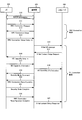
- FIG. 5 is a diagram showing a premise operation according to the embodiment.
- the operation according to LTE will be mainly described, but the same applies to the operation according to 5G (NR).
- 5G 5G
- the above-mentioned MME and AMF are collectively referred to as the upper node 400.
- RACH procedure is executed between the UE 200 and the base station 300.
- RACH procedure is a procedure for establishing synchronization between UE 200 and base station 300 by transmitting a RACH preamble from UE 200 to base station 300.
- step S11 the UE 200 sends an RRC Connection Request to the base station 300
- step S12 the base station 300 sends an RRC Connection Setup to the UE 200
- step S13 the UE 200 sends an RRC Connection Setup Complete to the base station. Send to 300.
- RRC connection setup procedures see TS36.331 v15.7.0 Chapter 5.3.3 or TS36.331 v15.7.0 Chapter 5.3.3).
- step S14 the base station 300 transmits an Initial UE message to the upper node 400.
- step S15 the higher-level node 400 transmits an InitialContextSetupRequest to the base station 300.
- the operation of step S15 is the operation of starting the setting of the S1 connection (TS36.413 v15.7.1 Chapter 8.3, TS38.413 v15.5.0 Chapter 8.3).
- step S16 the base station 300 transmits the UE Capability Inquiry to the UE 200.
- step S17 the UE 200 transmits UE Capability Information to the base station 300.
- UECapability Information includes at least UE200 UECapability. These procedures may be referred to as UE Capability transfer procedures (see TS36.331 v15.7.0 Chapter 5.6.3 or TS36.331 v15.7.0 Chapter 5.6.1).
- step S18 the base station 300 transmits the UE Capability Info Indication to the upper node 400.
- UE Capability Info Indication includes at least UE 200 UE Capability (TS36.413 v15.7.1 Chapter 8.9, TS38.413 v15.5.0 Chapter 8.14.1).
- step S19 the base station 300 transmits a Security Mode Command to the UE 200, and in step S20, the base station 300 transmits an RRC Connection Reconfiguration to the UE 200.
- step S21 the UE 200 transmits Security Mode Complete to the base station 300, and in step S22, the UE 200 transmits RRC Connection Reconfiguration Complete to the base station 300.
- the processing of steps S19 and S20 may be referred to as security procedures (see TS36.331 v15.7.0 Chapter 5.3.4 or TS36.331 v15.7.0 Chapter 5.3.4).
- the security procedure may be referred to as an AS (Access-Stratum) security procedure.
- step S23 the base station 300 transmits the InitialContextSetupResponse to the upper node 400.
- the operation of step S23 is the operation of completing the setting of the S1 connection (TS36.413 v15.7.1 Chapter 8.3, TS38.413 v15.5.0 Chapter 8.3).
- the UE Capability is acquired before the security procedure between the UE 200 and the base station 300.
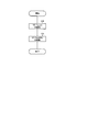
- Operation example 1 The operation example 1 according to the embodiment will be described below. As described above, the operation example 1 is the operation of the base station 300 in the case where "Store" is prohibited for the UE capability acquired before the security procedure in the network.
- the base station 300 detects the release of the UE context for the UE 200 that transmitted the UE capability before the security procedure.
- Release of the UE context may be detected when the UE 200 that sent the UE capability prior to the security procedure transitions from RRC Connected to RRC Idle or RRC Inactive.
- the release of the UE context may be detected when the UE 200, which sent the UE capability prior to the security procedure, performs a handover.
- the release of the UE context may be detected when the UE200, which sent the UE capability before the security procedure, performs cell reselection.
- the release of the UE context is detected when the radio quality of the UE200 that transmitted the UE capability deteriorates (when a Radio Link Failure is notified from the UE200, or when the base station determines that the UE200 is a Radio Link Failure, etc.). May In step S31, base station 300 deletes the UE Capability acquired prior to the security procedure. In other words, the base station 300 retains the UE capability while the UE 200 that transmitted the UE capability before the security procedure is RRC Connected, and deletes the UE capability when the UE 200 transitions to the RRC Idle or RRC Inactive.
- the UE capability acquired before the security procedure may be the UE capability acquired in cases other than unauthenticated emergency calls.
- the UE capability acquired before the security procedure may be the UE capability related to the UE 200 (for example, NB (Narrow Band) IoT UE) that uses a narrow band. That is, the base station 300 may execute the process of S31 when the UE capability acquired before the security procedure is acquired in a case other than the unauthenticated emergency call.
- the base station 300 may execute the processing of S31 when the UE capability acquired before the security procedure is the UE capability related to the UE 200 (for example, NB IoT UE) that uses a narrow band.
- the base station 300 in the case where it is prohibited to retain the UE capability acquired before the security procedure in the network for later use, continues to retain the UE capability. Can be suppressed.
- the base station 300 may receive the UE capability from the UE 200 after the security procedure. In such a case, the base station 300 may retain the UE capability acquired after the security procedure without deleting it even when the UE context is released.
- Operation example 2 The operation example 2 according to the embodiment will be described below.
- the operation example 2 is the operation of the base station 300 in the case where "Send" is prohibited for the UE capability acquired before the security procedure in the network.
- the following operation example 2-1 and operation example 2-2 can be considered.
- Operation example 2-1 The operation example 2-1 will be described below.
- operation example 2-1 a case where the UE 200 that has transmitted the UE capability before the security procedure performs a handover is illustrated.
- the base station 300 transmits a message related to the handover to the upper node 400.
- the message related to the handover may include a Handover Preparation Information Message.
- the Handover Preparation Information Message does not include the UE capability acquired before the security procedure. That is, in step S41, the base station 300 transmits a message that does not include the UE capability acquired before the security procedure to the upper node 400.
- the message related to the handover may include HANDOVER REQUIRED and HANDOVER REQUEST (TS36.413 v15.7.1, see Chapter 8.4) used in the S1 interface, and HANDOVER REQUIRED and HANDOVER REQUEST (TS38.413 v15.5.0) used in the N2 interface. (See Chapter 8.4) may be included.
- the message related to the handover may include HANDOVER REQUEST, RETRIEVE UE CONTEXT RESPONSE (TS36.423 v15.7.0 Chapter 8.2, Chapter 8.3) used in the X2 interface, and HANDOVER REQUEST, RETRIEVE UE CONTEXT RESPONSE (TS36.423 v15.7.0 Chapter 8.2, Chapter 8.3) used in the Xn interface. TS38.423 V15.5.0 Chapter 8.2) may be included.
- the Handover Preparation Information Message may include the UE-CapabilityRAT-ContainerList information element shown in FIG.
- the base station 300 sets the sequence length (SIZE) of the UE-CapabilityRAT-ContainerList to "0" to send the message not including the UE capability acquired before the security procedure to the upper node 400. You may send it.
- SIZE sequence length
- Such an information element whose sequence length (SIZE) is set to "0" is an example of an information element indicating that the UE capability acquired before the security procedure is not included.
- the UE capability acquired before the security procedure may be the UE capability acquired in cases other than unauthenticated emergency calls.
- the UE capability acquired before the security procedure may be the UE capability related to the UE 200 (for example, NB IoT UE) that uses a narrow band. That is, the base station 300 may execute the process of S41 when the UE capability acquired before the security procedure is acquired in a case other than the unauthenticated emergency call.
- the base station 300 may execute the processing of S41 when the UE capability acquired before the security procedure is the UE capability related to the UE 200 (for example, NB IoT UE) that uses a narrow band.
- the situation where the UE capability acquired before the security procedure is transmitted from the base station 300 can be transmitted. It can be avoided.
- the base station 300 may receive the UE capability from the UE 200 after the security procedure. In such a case, the base station 300 may send a message including UE capability acquired after the security procedure to the upper node 400.
- Operation example 2-2 The operation example 2-2 will be described below.
- operation example 2-2 a case where the UE 200 that has transmitted the UE capability before the security procedure performs a handover is illustrated.
- the base station 300 transmits a message related to the handover to the upper node 400.
- the message related to the handover may include a Handover Preparation Information Message.
- the Handover Preparation Information Message includes an information element indicating that the UE capability is invalid, in addition to the UE capability acquired before the security procedure. That is, in step S42, the base station 300 transmits a message including the UE capability to the upper node 400 together with an information element indicating that the UE capability acquired before the security procedure is invalid.
- the Handover Preparation Information Message may include an information element called "invalidUECapability" as shown in FIG. "InvalidUECapability" is an example of an information element indicating that the UE capability acquired before the security procedure is invalid. Note that FIG. 10 illustrates a Handover Preparation Information Message related to NB IoT UE.
- the UE capability acquired before the security procedure may be the UE capability acquired in cases other than unauthenticated emergency calls.
- the UE capability acquired before the security procedure may be the UE capability related to the UE 200 (for example, NB IoT UE) that uses a narrow band. That is, the base station 300 may execute the process of S42 when the UE capability acquired before the security procedure is acquired in a case other than the unauthenticated emergency call.
- the base station 300 may execute the processing of S42 when the UE capability acquired before the security procedure is the UE capability related to the UE 200 (for example, NB IoT UE) that uses a narrow band.
- an information element indicating that the UE capability is invalid may be added, so that the operation example 2-1 is compared with the above-mentioned operation example 2-1. It is possible to reduce the load related to changing the operation of the existing UE.
- the base station 300 may receive the UE capability from the UE 200 after the security procedure. In such a case, the base station 300 may send a message including UE capability acquired after the security procedure to the upper node 400.
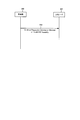
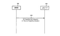
- operation example 3 is the operation of the base station 300 in the case where "Send" is permitted for the UE capability acquired before the security procedure in the network.
- step S50 the base station 300 transmits the UE Capability Info Indication to the upper node 400.
- the UE Capability Info Indication includes an information element indicating whether or not the UE Capability was acquired before the security procedure.
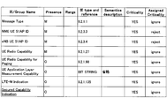
- UE Capability Info Indication includes the information elements shown in Fig. 12 (TS36.413 v15.7.1 Chapter 9.1.10, TS38.413 v15.5.0 Chapter 9.2.13).
- UECapabilityInfoIndication includes "SecuredCapabilityIndication”.
- “SecuredCapabilityIndication” is an example of an information element indicating whether or not UEcapability was acquired before the security procedure.
- the UE capability acquired before the security procedure may be the UE capability acquired in the case of an unauthenticated emergency call.
- the UE capability acquired before the security procedure may be the UE capability related to the UE 200 (for example, NB IoT UE) that uses a narrow band. That is, the base station 300 may execute the processing of S50 when the UE capability acquired before the security procedure is acquired in the case of an unauthenticated emergency call.
- the base station 300 may execute the processing of S50 when the UE capability acquired before the security procedure is the UE capability related to the UE 200 (for example, NB IoT UE) that uses a narrow band.
- UE Capability Info Indication has been described, but operation example 3 is not limited to this.
- An information element indicating whether UE capability was acquired before the security procedure may be included in the message related to the handover.
- the message related to the handover may include a Handover Preparation Information Message.
- the HandoverPreparationInformationMessage may include an information element called "ueCapabilitySecured” as shown in FIG. “UeCapabilitySecured” is an example of an information element indicating whether or not UEcapability was acquired before the security procedure.
- the interface between the base station 300 and the upper node 400 has been illustrated.
- the embodiment is not limited to this.
- Operation examples 1 to 3 are also applicable to other interfaces.
- the above-mentioned operation examples 1 to 3 can be applied to one or more interfaces selected from the NG (N2) interface, the X2 interface, the Xn interface, the N26 interface, and the like. Therefore, the other node to which the message is sent is not limited to the higher-level node 400 such as MME or AMF, but other base stations (for example, eNB 111 and). gNB121) may be included.
- the base station 300 is not limited to the base station, and may include MME, AMF, or the like.
- Such a handover may include a handover within the same access network (Intra-RAT handover) or may include a handover between different access networks (Inter-RAT handover). In addition to handover, it may include the case of acquiring UE capability from a higher-level node or another base station (at the time of RRC Connection Resume or UE re-establishment).
- each functional block may be realized by using one device that is physically or logically connected, or directly or indirectly (for example, by two or more devices that are physically or logically separated). , Wired, wireless, etc.) and may be realized using these plurality of devices.
- the functional block may be realized by combining the software with the one device or the plurality of devices.
- Functions include judgment, decision, judgment, calculation, calculation, processing, derivation, investigation, search, confirmation, reception, transmission, output, access, solution, selection, selection, establishment, comparison, assumption, expectation, and assumption. Broadcasting, notifying, communicating, forwarding, configuring, reconfiguring, allocating, mapping, assigning, etc., but limited to these I can't.
- a functional block (constituent unit) for functioning transmission is called a transmitting unit or a transmitter.
- the method of realizing each of them is not particularly limited.
- FIG. 14 is a diagram showing an example of the hardware configuration of the device.
- the device may be configured as a computer device including a processor 1001, a memory 1002, a storage 1003, a communication device 1004, an input device 1005, an output device 1006, a bus 1007, and the like.
- the word “device” can be read as a circuit, device, unit, etc.
- the hardware configuration of the device may be configured to include one or more of the devices shown in the figure, or may be configured not to include some of the devices.
- Each functional block of the device (see FIG. 3) is realized by any hardware element of the computer device or a combination of the hardware elements.
- the processor 1001 performs the calculation, controls the communication by the communication device 1004, and the memory. It is realized by controlling at least one of reading and writing of data in 1002 and storage 1003.
- Processor 1001 operates, for example, an operating system to control the entire computer.
- the processor 1001 may be composed of a central processing unit (CPU) including an interface with peripheral devices, a control device, an arithmetic unit, a register, and the like.
- CPU central processing unit
- the processor 1001 reads a program (program code), a software module, data, etc. from at least one of the storage 1003 and the communication device 1004 into the memory 1002, and executes various processes according to these.
- a program program code
- a program that causes a computer to execute at least a part of the operations described in the above-described embodiment is used.
- the various processes described above may be executed by one processor 1001 or may be executed simultaneously or sequentially by two or more processors 1001.
- Processor 1001 may be implemented by one or more chips.
- the program may be transmitted from the network via a telecommunication line.
- the memory 1002 is a computer-readable recording medium, and is composed of at least one such as ReadOnlyMemory (ROM), ErasableProgrammableROM (EPROM), Electrically ErasableProgrammableROM (EEPROM), and RandomAccessMemory (RAM). May be done.
- the memory 1002 may be referred to as a register, a cache, a main memory (main storage device), or the like.
- the memory 1002 can store a program (program code), a software module, or the like that can execute the method according to the embodiment of the present disclosure.
- the storage 1003 is a computer-readable recording medium, for example, an optical disk such as a Compact Disc ROM (CD-ROM), a hard disk drive, a flexible disk, an optical magnetic disk (for example, a compact disk, a digital versatile disk, or a Blu-ray). It may consist of at least one (registered trademark) disk), smart card, flash memory (eg, card, stick, key drive), floppy (registered trademark) disk, magnetic strip, and the like.
- Storage 1003 may be referred to as auxiliary storage.
- the recording medium described above may be, for example, a database, server or other suitable medium containing at least one of memory 1002 and storage 1003.
- the communication device 1004 is hardware (transmission / reception device) for communicating between computers via at least one of a wired network and a wireless network, and is also referred to as, for example, a network device, a network controller, a network card, a communication module, or the like.
- the communication device 1004 includes, for example, a high frequency switch, a duplexer, a filter, a frequency synthesizer, etc. in order to realize at least one of frequency division duplex (FDD) and time division duplex (TDD). It may be composed of.
- FDD frequency division duplex
- TDD time division duplex
- the input device 1005 is an input device (for example, a keyboard, a mouse, a microphone, a switch, a button, a sensor, etc.) that accepts input from the outside.
- the output device 1006 is an output device (for example, a display, a speaker, an LED lamp, etc.) that outputs to the outside.
- the input device 1005 and the output device 1006 may have an integrated configuration (for example, a touch panel).
- Bus 1007 may be configured using a single bus or may be configured using different buses for each device.
- the device includes hardware such as a microprocessor, a digital signal processor (Digital Signal Processor: DSP), an Application Specific Integrated Circuit (ASIC), a Programmable Logic Device (PLD), and a Field Programmable Gate Array (FPGA).
- DSP Digital Signal Processor
- ASIC Application Specific Integrated Circuit
- PLD Programmable Logic Device
- FPGA Field Programmable Gate Array
- the hardware may realize a part or all of each functional block.
- processor 1001 may be implemented using at least one of these hardware.
- information notification includes physical layer signaling (for example, Downlink Control Information (DCI), Uplink Control Information (UCI), upper layer signaling (eg, RRC signaling, Medium Access Control (MAC) signaling, broadcast information (Master Information Block)). (MIB), System Information Block (SIB)), other signals or a combination thereof.
- DCI Downlink Control Information
- UCI Uplink Control Information
- RRC signaling may also be referred to as an RRC message, for example, RRC Connection Setup. ) Message, RRC Connection Reconfiguration message, etc. may be used.
- LTE LongTermEvolution
- LTE-A LTE-Advanced
- SUPER3G IMT-Advanced
- 4G 4th generation mobile communication system
- 5G 5th generation mobile communication system
- FutureRadioAccess FAA
- NewRadio NR
- W-CDMA registered trademark
- GSM registered trademark
- CDMA2000 Code Division Multiple Access 2000
- UMB UltraMobile Broadband
- IEEE802.11 Wi-Fi (registered trademark)
- IEEE802.16 WiMAX®
- IEEE802.20 Ultra-WideBand (UWB), Bluetooth®, and other systems that utilize appropriate systems and at least one of the next-generation systems extended based on them.
- a plurality of systems may be applied in combination (for example, a combination of at least one of LTE and LTE-A and 5G).
- the specific operation performed by the base station in the present disclosure may be performed by its upper node.
- various operations performed for communication with a terminal are performed by the base station and other network nodes other than the base station (for example, MME or). It is clear that it can be done by at least one of (but not limited to, S-GW, etc.).
- S-GW network node
- the case where there is one network node other than the base station is illustrated above, it may be a combination of a plurality of other network nodes (for example, MME and S-GW).
- Information and signals can be output from the upper layer (or lower layer) to the lower layer (or upper layer).
- Input / output may be performed via a plurality of network nodes.
- the input / output information may be stored in a specific location (for example, memory) or may be managed using a management table.
- the input / output information can be overwritten, updated, or added.
- the output information may be deleted.
- the input information may be transmitted to another device.
- the determination may be made by a value represented by 1 bit (0 or 1), by a boolean value (Boolean: true or false), or by comparing numerical values (for example, a predetermined value). It may be done by comparison with the value).
- the notification of predetermined information (for example, the notification of "being X") is not limited to the explicit one, but is performed implicitly (for example, the notification of the predetermined information is not performed). May be good.
- Software whether referred to as software, firmware, middleware, microcode, hardware description language, or by any other name, is an instruction, instruction set, code, code segment, program code, program, subprogram, software module.
- Applications, software applications, software packages, routines, subroutines, objects, executable files, execution threads, procedures, features, etc. should be broadly interpreted.
- software, instructions, information, etc. may be transmitted and received via a transmission medium.
- a transmission medium For example, a website, where the software uses at least one of wired technology (coaxial cable, fiber optic cable, twisted pair, Digital Subscriber Line (DSL), etc.) and wireless technology (infrared, microwave, etc.).
- wired technology coaxial cable, fiber optic cable, twisted pair, Digital Subscriber Line (DSL), etc.
- wireless technology infrared, microwave, etc.
- the information, signals, etc. described in this disclosure may be represented using any of a variety of different techniques.
- data, instructions, commands, information, signals, bits, symbols, chips, etc. that may be referred to throughout the above description are voltages, currents, electromagnetic waves, magnetic fields or magnetic particles, light fields or photons, or any of these. It may be represented by a combination of.
- a channel and a symbol may be a signal (signaling).
- the signal may be a message.
- the component carrier (CC) may be referred to as a carrier frequency, a cell, a frequency carrier, or the like.
- system and “network” used in this disclosure are used interchangeably.
- the information, parameters, etc. described in the present disclosure may be expressed using absolute values, relative values from predetermined values, or using other corresponding information. It may be represented.
- the radio resource may be one indicated by an index.
- Base Station BS
- Wireless Base Station Wireless Base Station
- NodeB NodeB
- eNodeB eNodeB
- gNodeB gNodeB
- Base stations are sometimes referred to by terms such as macrocells, small cells, femtocells, and picocells.
- the base station can accommodate one or more (for example, three) cells (also called sectors). When a base station accommodates multiple cells, the entire base station coverage area can be divided into multiple smaller areas, each smaller area being a base station subsystem (eg, a small indoor base station (Remote Radio)). Communication services can also be provided by Head: RRH).
- a base station subsystem eg, a small indoor base station (Remote Radio)
- Communication services can also be provided by Head: RRH).
- cell refers to a part or all of a base station that provides communication services in this coverage and at least one of the coverage areas of a base station subsystem.
- MS mobile station
- UE user equipment
- terminal terminal
- Mobile stations can be used by those skilled in the art as subscriber stations, mobile units, subscriber units, wireless units, remote units, mobile devices, wireless devices, wireless communication devices, remote devices, mobile subscriber stations, access terminals, mobile terminals, wireless. It may also be referred to as a terminal, remote terminal, handset, user agent, mobile client, client, or some other suitable term.
- At least one of the base station and the mobile station may be called a transmitting device, a receiving device, a communication device, or the like. At least one of the base station and the mobile station may be a device mounted on the mobile body, the mobile body itself, or the like.
- the moving body may be a vehicle (for example, a car, an airplane, etc.), an unmanned moving body (for example, a drone, an autonomous vehicle, etc.), or a robot (manned or unmanned type). ) May be.
- at least one of the base station and the mobile station includes a device that does not necessarily move during communication operation.
- at least one of a base station and a mobile station may be an Internet of Things (IoT) device such as a sensor.
- IoT Internet of Things
- the base station in the present disclosure may be read as a mobile station (user terminal, the same applies hereinafter).
- communication between a base station and a mobile station has been replaced with communication between a plurality of mobile stations (for example, it may be called Device-to-Device (D2D), Vehicle-to-Everything (V2X), etc.).
- D2D Device-to-Device
- V2X Vehicle-to-Everything
- Each aspect / embodiment of the present disclosure may be applied to the configuration.
- the mobile station may have the functions of the base station.
- words such as "up” and “down” may be read as words corresponding to communication between terminals (for example, "side”).
- an uplink channel, a downlink channel, and the like may be read as a side channel.
- the mobile station in the present disclosure may be read as a base station.
- the base station may have the functions of the mobile station.
- the wireless frame may be composed of one or more frames in the time domain. Each one or more frames in the time domain may be referred to as a subframe.
- the subframe may be further composed of one or more slots in the time domain.
- the subframe may have a fixed time length (eg, 1 ms) that is independent of numerology.
- the numerology may be a communication parameter that applies to at least one of the transmission and reception of a signal or channel.
- Numerology includes, for example, SubCarrier Spacing (SCS), bandwidth, symbol length, cyclic prefix length, transmission time interval (TTI), number of symbols per TTI, wireless frame configuration, transmission / reception. It may indicate at least one of a specific filtering process performed by the machine in the frequency domain, a specific windowing process performed by the transmitter / receiver in the time domain, and the like.
- the slot may be composed of one or more symbols (Orthogonal Frequency Division Multiple Access (OFDM) symbol, Single Carrier Frequency Division Multiple Access (SC-FDMA) symbol, etc.) in the time domain. Slots may be unit of time based on numerology.
- OFDM Orthogonal Frequency Division Multiple Access
- SC-FDMA Single Carrier Frequency Division Multiple Access
- the slot may include a plurality of mini slots. Each minislot may consist of one or more symbols in the time domain.
- the mini-slot may also be referred to as a sub-slot.
- a minislot may consist of a smaller number of symbols than the slot.
- PDSCH (or PUSCH) transmitted in time units larger than the minislot may be referred to as PDSCH (or PUSCH) mapping type A.
- the PDSCH (or PUSCH) transmitted using the minislot may be referred to as PDSCH (or PUSCH) mapping type B.
- the wireless frame, subframe, slot, minislot and symbol all represent the time unit when transmitting a signal.
- the radio frame, subframe, slot, minislot and symbol may have different names corresponding to each.
- one subframe may be referred to as a transmission time interval (TTI)
- TTI transmission time interval
- TTI transmission time interval
- TTI transmission time interval
- TTI transmission time interval
- TTI transmission time interval
- TTI transmission time interval
- TTI slot or one minislot
- at least one of the subframe and TTI may be a subframe (1ms) in existing LTE, a period shorter than 1ms (eg, 1-13 symbols), or a period longer than 1ms. It may be.
- the unit representing TTI may be called a slot, a mini slot, or the like instead of a subframe.
- TTI refers to, for example, the minimum time unit of scheduling in wireless communication.
- a base station schedules each user terminal to allocate radio resources (frequency bandwidth that can be used in each user terminal, transmission power, etc.) in TTI units.
- the definition of TTI is not limited to this.
- the TTI may be a transmission time unit such as a channel-encoded data packet (transport block), a code block, or a code word, or may be a processing unit such as scheduling or link adaptation.
- the time interval for example, the number of symbols
- the transport block, code block, code word, etc. may be shorter than the TTI.
- one or more TTIs may be the minimum time unit for scheduling. Further, the number of slots (number of mini-slots) constituting the minimum time unit of the scheduling may be controlled.
- a TTI having a time length of 1 ms may be called a normal TTI (TTI in LTE Rel.8-12), a normal TTI, a long TTI, a normal subframe, a normal subframe, a long subframe, a slot, or the like.
- TTIs shorter than normal TTIs may be referred to as shortened TTIs, short TTIs, partial TTIs (partial or fractional TTIs), shortened subframes, short subframes, minislots, subslots, slots, and the like.
- the long TTI (for example, normal TTI, subframe, etc.) may be read as a TTI having a time length of more than 1 ms
- the short TTI (for example, shortened TTI, etc.) may be read as less than the TTI length of the long TTI and 1 ms. It may be read as a TTI having the above TTI length.
- the resource block (RB) is a resource allocation unit in the time domain and the frequency domain, and may include one or a plurality of continuous subcarriers in the frequency domain.
- the number of subcarriers contained in RB may be the same regardless of numerology, and may be, for example, 12.
- the number of subcarriers contained in the RB may be determined based on numerology.
- the time domain of RB may include one or more symbols, and may have a length of 1 slot, 1 mini slot, 1 subframe, or 1 TTI.
- Each 1TTI, 1 subframe, etc. may be composed of one or a plurality of resource blocks.
- One or more RBs include a physical resource block (Physical RB: PRB), a sub-carrier group (Sub-Carrier Group: SCG), a resource element group (Resource Element Group: REG), a PRB pair, an RB pair, and the like. May be called.
- Physical RB Physical RB: PRB
- SCG sub-carrier Group
- REG resource element group
- PRB pair an RB pair, and the like. May be called.
- the resource block may be composed of one or a plurality of resource elements (ResourceElement: RE).
- RE resource elements
- 1RE may be a radio resource area of 1 subcarrier and 1 symbol.
- Bandwidth Part (which may also be called partial bandwidth, etc.) may represent a subset of consecutive common resource blocks (RBs) for a neurology in a carrier. Good.
- the common RB may be specified by the index of the RB with respect to the common reference point of the carrier.
- PRBs may be defined in a BWP and numbered within that BWP.
- BWP may include BWP for UL (UL BWP) and BWP for DL (DL BWP).
- BWP for UL
- DL BWP BWP for DL
- One or more BWPs may be set in one carrier for the UE.
- At least one of the configured BWPs may be active, and the UE may not expect to send or receive a given signal / channel outside the active BWP.
- “cell”, “carrier” and the like in this disclosure may be read as “BWP”.
- the above-mentioned structures such as wireless frames, subframes, slots, mini slots and symbols are merely examples.
- the number of subframes contained in a wireless frame the number of slots per subframe or wireless frame, the number of minislots contained within a slot, the number of symbols and RBs contained in a slot or minislot, included in RB.
- the number of subcarriers, the number of symbols in the TTI, the symbol length, the cyclic prefix (CP) length, and other configurations can be changed in various ways.
- connection means any direct or indirect connection or connection between two or more elements, and each other. It can include the presence of one or more intermediate elements between two “connected” or “combined” elements.
- the connection or connection between the elements may be physical, logical, or a combination thereof.
- connection may be read as "access”.
- the two elements use at least one of one or more wires, cables and printed electrical connections, and, as some non-limiting and non-comprehensive examples, the radio frequency domain. Can be considered to be “connected” or “coupled” to each other using electromagnetic energies having wavelengths in the microwave and light (both visible and invisible) regions.
- the reference signal may also be abbreviated as Reference Signal (RS) and may be referred to as the Pilot depending on the applied standard.
- RS Reference Signal
- each of the above devices may be replaced with a "part”, a “circuit”, a “device”, or the like.
- references to elements using designations such as “first”, “second” as used in this disclosure does not generally limit the quantity or order of those elements. These designations can be used in the present disclosure as a convenient way to distinguish between two or more elements. Thus, references to the first and second elements do not mean that only two elements can be adopted there, or that the first element must somehow precede the second element.
- determining and “determining” used in this disclosure may include a wide variety of actions.
- “Judgment” and “decision” are, for example, judgment (judging), calculation (calculating), calculation (computing), processing (processing), derivation (deriving), investigation (investigating), search (looking up, search, inquiry). (For example, searching in a table, database or another data structure), ascertaining may be regarded as “judgment” or “decision”.
- judgment and “decision” are receiving (for example, receiving information), transmitting (for example, transmitting information), input (input), output (output), and access.
- Accessing (for example, accessing data in memory) may be regarded as "judgment” or “decision”.
- judgment and “decision” mean that the things such as solving, selecting, choosing, establishing, and comparing are regarded as “judgment” and “decision”. Can include. That is, “judgment” and “decision” may include considering some action as “judgment” and “decision”. Further, “judgment (decision)” may be read as “assuming”, “expecting”, “considering” and the like.
- the term "A and B are different” may mean “A and B are different from each other”.
- the term may mean that "A and B are different from C”.
- Terms such as “separate” and “combined” may be interpreted in the same way as “different”.
- 100 ... wireless communication system 110 ... E-UTRAN, 111 ... eNB, 120 ... NG RAN, 121 ... gNB 121, 130 ... core network, 200 ... UE, 210 ... receiver, 220 ... transmitter, 230 ... control, 300 ... base station, 310 ... receiver, 320 ... transmitter, 330 ... control, 400 ... higher node, 1001 ... processor, 1002 ... memory, 1003 ... storage, 1004 ... communication device, 1005 ... input device, 1006 ... output device , 1007 ... Bus
Landscapes
- Engineering & Computer Science (AREA)
- Computer Networks & Wireless Communication (AREA)
- Signal Processing (AREA)
- Databases & Information Systems (AREA)
- Computer Security & Cryptography (AREA)
- Mobile Radio Communication Systems (AREA)
Abstract
L'invention concerne une station de base comprenant : une unité de réception qui reçoit une capacité de terminal d'un terminal avant une procédure de sécurité ; et une unité de commande qui, conformément à la libération d'un contexte de terminal concernant le terminal, supprime la capacité de terminal acquise avant la procédure de sécurité.
Priority Applications (2)
| Application Number | Priority Date | Filing Date | Title |
|---|---|---|---|
| PCT/JP2019/051599 WO2021131069A1 (fr) | 2019-12-27 | 2019-12-27 | Station de base et procède de communication sans fil |
| US17/788,893 US20230052093A1 (en) | 2019-12-27 | 2019-12-27 | Base station and radio communication method |
Applications Claiming Priority (1)
| Application Number | Priority Date | Filing Date | Title |
|---|---|---|---|
| PCT/JP2019/051599 WO2021131069A1 (fr) | 2019-12-27 | 2019-12-27 | Station de base et procède de communication sans fil |
Publications (1)
| Publication Number | Publication Date |
|---|---|
| WO2021131069A1 true WO2021131069A1 (fr) | 2021-07-01 |
Family
ID=76573814
Family Applications (1)
| Application Number | Title | Priority Date | Filing Date |
|---|---|---|---|
| PCT/JP2019/051599 WO2021131069A1 (fr) | 2019-12-27 | 2019-12-27 | Station de base et procède de communication sans fil |
Country Status (2)
| Country | Link |
|---|---|
| US (1) | US20230052093A1 (fr) |
| WO (1) | WO2021131069A1 (fr) |
-
2019
- 2019-12-27 WO PCT/JP2019/051599 patent/WO2021131069A1/fr active Application Filing
- 2019-12-27 US US17/788,893 patent/US20230052093A1/en active Pending
Non-Patent Citations (2)
| Title |
|---|
| ERICSSON: "Security of RRC UE capability transfer procedure in 5GS", 3GPP DRAFT; S3-192862_SECURITY_OF_UE_CAP_TRANSFER_5GS, 3RD GENERATION PARTNERSHIP PROJECT (3GPP), MOBILE COMPETENCE CENTRE ; 650, ROUTE DES LUCIOLES ; F-06921 SOPHIA-ANTIPOLIS CEDEX ; FRANCE, vol. SA WG3, no. Wroclaw (Poland); 20190826 - 20190830, 19 August 2019 (2019-08-19), Mobile Competence Centre ; 650, route des Lucioles ; F-06921 Sophia-Antipolis Cedex ; France , XP051776695 * |
| ERICSSON: "Security of RRC UE capability transfer procedure in EPS", 3GPP DRAFT; S3-192861_SECURITY_OF_UE_CAP_TRANSFER_EPS, 3RD GENERATION PARTNERSHIP PROJECT (3GPP), MOBILE COMPETENCE CENTRE ; 650, ROUTE DES LUCIOLES ; F-06921 SOPHIA-ANTIPOLIS CEDEX ; FRANCE, vol. SA WG3, no. Wroclaw (Poland); 20190826 - 20190830, 19 August 2019 (2019-08-19), Mobile Competence Centre ; 650, route des Lucioles ; F-06921 Sophia-Antipolis Cedex ; France , XP051776694 * |
Also Published As
| Publication number | Publication date |
|---|---|
| US20230052093A1 (en) | 2023-02-16 |
Similar Documents
| Publication | Publication Date | Title |
|---|---|---|
| WO2017195471A1 (fr) | Dispositif utilisateur et station de base | |
| US20220338087A1 (en) | Terminal | |
| WO2020230201A1 (fr) | Dispositif utilisateur et dispositif de station de base | |
| JP7096915B2 (ja) | ユーザ装置及び基地局装置 | |
| JP7098762B2 (ja) | ユーザ装置及び基地局装置 | |
| US20220394528A1 (en) | Radio base station and terminal | |
| WO2022097755A1 (fr) | Terminal et station de base sans fil | |
| EP4290913A1 (fr) | Station de base sans fil, système et procédé de communication sans fil | |
| US20240147330A1 (en) | Terminal | |
| WO2022085158A1 (fr) | Terminal et station de base sans fil | |
| WO2020246185A1 (fr) | Terminal et station de base | |
| WO2021038920A1 (fr) | Terminal, station de base et procédé de communication | |
| JP7170842B2 (ja) | ユーザ装置及び基地局装置 | |
| WO2021065016A1 (fr) | Terminal et procédé de communication | |
| US20220279406A1 (en) | Terminal | |
| WO2021131069A1 (fr) | Station de base et procède de communication sans fil | |
| WO2021131066A1 (fr) | Station de base et procédé de communication sans fil | |
| WO2021161529A1 (fr) | Terminal et procédé de communication sans fil | |
| WO2022039189A1 (fr) | Terminal et système de communication sans fil | |
| WO2021181485A1 (fr) | Terminal | |
| WO2022074729A1 (fr) | Dispositif de communication | |
| WO2023276011A1 (fr) | Terminal et procédé de communication | |
| WO2022153462A1 (fr) | Terminal et procédé de communication sans fil | |
| WO2022215230A1 (fr) | Terminal et procédé de communication sans fil | |
| WO2021075378A1 (fr) | Terminal |
Legal Events
| Date | Code | Title | Description |
|---|---|---|---|
| 121 | Ep: the epo has been informed by wipo that ep was designated in this application |
Ref document number: 19957139 Country of ref document: EP Kind code of ref document: A1 |
|
| NENP | Non-entry into the national phase |
Ref country code: DE |
|
| 122 | Ep: pct application non-entry in european phase |
Ref document number: 19957139 Country of ref document: EP Kind code of ref document: A1 |
|
| NENP | Non-entry into the national phase |
Ref country code: JP |