WO2021131002A1 - ネットワーク管理装置、方法およびプログラム - Google Patents
ネットワーク管理装置、方法およびプログラム Download PDFInfo
- Publication number
- WO2021131002A1 WO2021131002A1 PCT/JP2019/051316 JP2019051316W WO2021131002A1 WO 2021131002 A1 WO2021131002 A1 WO 2021131002A1 JP 2019051316 W JP2019051316 W JP 2019051316W WO 2021131002 A1 WO2021131002 A1 WO 2021131002A1
- Authority
- WO
- WIPO (PCT)
- Prior art keywords
- information
- layer
- entity
- equipment
- failure
- Prior art date
- Legal status (The legal status is an assumption and is not a legal conclusion. Google has not performed a legal analysis and makes no representation as to the accuracy of the status listed.)
- Ceased
Links
Images












Classifications
-
- H—ELECTRICITY
- H04—ELECTRIC COMMUNICATION TECHNIQUE
- H04L—TRANSMISSION OF DIGITAL INFORMATION, e.g. TELEGRAPHIC COMMUNICATION
- H04L41/00—Arrangements for maintenance, administration or management of data switching networks, e.g. of packet switching networks
- H04L41/26—Arrangements for maintenance, administration or management of data switching networks, e.g. of packet switching networks using dedicated tools for LAN [Local Area Network] management
-
- H—ELECTRICITY
- H04—ELECTRIC COMMUNICATION TECHNIQUE
- H04L—TRANSMISSION OF DIGITAL INFORMATION, e.g. TELEGRAPHIC COMMUNICATION
- H04L41/00—Arrangements for maintenance, administration or management of data switching networks, e.g. of packet switching networks
- H04L41/06—Management of faults, events, alarms or notifications
- H04L41/0631—Management of faults, events, alarms or notifications using root cause analysis; using analysis of correlation between notifications, alarms or events based on decision criteria, e.g. hierarchy, tree or time analysis
- H04L41/065—Management of faults, events, alarms or notifications using root cause analysis; using analysis of correlation between notifications, alarms or events based on decision criteria, e.g. hierarchy, tree or time analysis involving logical or physical relationship, e.g. grouping and hierarchies
-
- H—ELECTRICITY
- H04—ELECTRIC COMMUNICATION TECHNIQUE
- H04L—TRANSMISSION OF DIGITAL INFORMATION, e.g. TELEGRAPHIC COMMUNICATION
- H04L41/00—Arrangements for maintenance, administration or management of data switching networks, e.g. of packet switching networks
- H04L41/06—Management of faults, events, alarms or notifications
- H04L41/0604—Management of faults, events, alarms or notifications using filtering, e.g. reduction of information by using priority, element types, position or time
- H04L41/0627—Management of faults, events, alarms or notifications using filtering, e.g. reduction of information by using priority, element types, position or time by acting on the notification or alarm source
-
- H—ELECTRICITY
- H04—ELECTRIC COMMUNICATION TECHNIQUE
- H04L—TRANSMISSION OF DIGITAL INFORMATION, e.g. TELEGRAPHIC COMMUNICATION
- H04L41/00—Arrangements for maintenance, administration or management of data switching networks, e.g. of packet switching networks
- H04L41/06—Management of faults, events, alarms or notifications
- H04L41/0631—Management of faults, events, alarms or notifications using root cause analysis; using analysis of correlation between notifications, alarms or events based on decision criteria, e.g. hierarchy, tree or time analysis
-
- H—ELECTRICITY
- H04—ELECTRIC COMMUNICATION TECHNIQUE
- H04L—TRANSMISSION OF DIGITAL INFORMATION, e.g. TELEGRAPHIC COMMUNICATION
- H04L41/00—Arrangements for maintenance, administration or management of data switching networks, e.g. of packet switching networks
- H04L41/06—Management of faults, events, alarms or notifications
- H04L41/0677—Localisation of faults
-
- H—ELECTRICITY
- H04—ELECTRIC COMMUNICATION TECHNIQUE
- H04L—TRANSMISSION OF DIGITAL INFORMATION, e.g. TELEGRAPHIC COMMUNICATION
- H04L47/00—Traffic control in data switching networks
-
- H—ELECTRICITY
- H04—ELECTRIC COMMUNICATION TECHNIQUE
- H04L—TRANSMISSION OF DIGITAL INFORMATION, e.g. TELEGRAPHIC COMMUNICATION
- H04L41/00—Arrangements for maintenance, administration or management of data switching networks, e.g. of packet switching networks
- H04L41/02—Standardisation; Integration
- H04L41/0233—Object-oriented techniques, for representation of network management data, e.g. common object request broker architecture [CORBA]
Definitions
- Embodiments of the present invention relate to network management devices, methods and programs.
- a pseudo failure occurs in a building, communication cable, communication device, or communication medium on the physical layer that realizes a service by a communication network, and the effect of this failure on the service.
- There is a technique for identifying the influence on the service by the same method regardless of the type of service and NW see, for example, Non-Patent Document 1).
- Non-Patent Document 1 does not provide a means for identifying a candidate for a location on the physical layer that has caused a failure in the transmission layer, service layer, or the like on the logical layer. ..
- the present invention has been made by paying attention to the above circumstances, and an object of the present invention is a network management device capable of identifying candidates for equipment that causes a failure on the logical layer of a communication network. , To provide methods and programs.
- the network management device has a correspondence relationship between an information object related to a logical layer of a network configuration, an information object related to a physical layer, and an information object related to an equipment layer which is an object in which an information object related to the physical layer is housed.
- the acquisition unit that acquires the information object related to the failure occurrence route in the logical layer of the network configuration from the storage device, and the information object related to the equipment layer stored in the storage device.
- the equipment layer and the information object related to the physical layer, which are associated with the information object related to the failure occurrence route acquired by the acquisition unit, are searched for as candidates for equipment causing the failure.
- the network management method has a correspondence relationship between an information object related to a logical layer of a network configuration, an information object related to a physical layer, and an information object related to an equipment layer which is an object in which an information object related to the physical layer is housed.
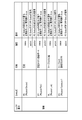
- FIG. 1 is a diagram showing an example of objectification of equipment layers in a network configuration applied to a network management device according to an embodiment of the present invention in a table format.
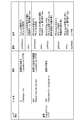
- FIG. 2 is a diagram showing an example of objectification of a physical layer in a network configuration applied to a network management device according to an embodiment of the present invention in a table format.
- FIG. 3 is a diagram showing an example of objectification of the Logical Device layer in the network configuration applied to the network management device according to the embodiment of the present invention in a table format.
- FIG. 4 is a diagram showing an example of objectification of a communication layer in a network configuration applied to a network management device according to an embodiment of the present invention in a table format.
- FIG. 1 is a diagram showing an example of objectification of equipment layers in a network configuration applied to a network management device according to an embodiment of the present invention in a table format.
- FIG. 2 is a diagram showing an example of objectification of a physical layer in a network configuration applied to a network management
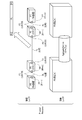
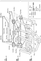
- FIG. 5 is a diagram showing an application example of a facility Entity and a physical Entity applied to the network management device according to the embodiment of the present invention.
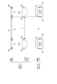
- FIG. 6 is a diagram showing an application example of a physical Entity and a logical Entity applied to the network management device according to the embodiment of the present invention.
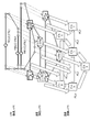
- FIG. 7 is a diagram showing an example of objectification of a network configuration applied to a network management device according to an embodiment of the present invention.
- FIG. 8 is a diagram showing an example of designating a failure path (pass) in a network configuration applied to the network management device according to the embodiment of the present invention.
- FIG. 9 is a diagram showing an example of searching for a physical resource (Resource) used by a failure path in a network configuration applied to a network management device according to an embodiment of the present invention.
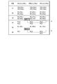
- FIG. 10 is a diagram showing an example of a search result of a physical resource used by a failure path in a network configuration applied to a network management device according to an embodiment of the present invention in a table format.
- FIG. 11 is a diagram showing an example of searching for physical resources having a common failure path in the network configuration applied to the network management device according to the embodiment of the present invention.
- FIG. 12 is a diagram showing an example of a search result of equipment resources having a common failure path in the network configuration applied to the network management device according to the embodiment of the present invention in a table format.
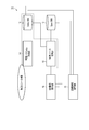
- FIG. 13 is a diagram showing an example of a software configuration of a network management device according to an embodiment of the present invention.
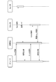
- FIG. 14 is a sequence diagram showing an example of a procedure for registering equipment information by the network management device according to the embodiment of the present invention.
- FIG. 15 is a diagram showing an example of Spec (equipment layer and physical layer) of equipment information held by the network management device according to the embodiment of the present invention in a table format.
- FIG. 16 is a diagram showing an example of a Spec (logical layer) of equipment information held by the network management device according to the embodiment of the present invention in a table format.
- FIG. 17 is a diagram showing an example of use of Spec and Entity class (class) by the network management device according to the embodiment of the present invention.
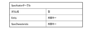
- FIG. 18 is a diagram showing an example of a schema of a specification table of equipment information defined by a network management device according to an embodiment of the present invention in a table format.
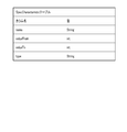
- FIG. 19 is a diagram showing an example of a schema of a Spec Characteristic table of equipment information defined by a network management device according to an embodiment of the present invention in a table format.
- FIG. 20 is a diagram showing an example of the schema of the Entity table of the equipment information defined by the network management device according to the embodiment of the present invention in a table format.
- FIG. 21 is a diagram showing an example of the schema of the CharacteristicValue table of equipment information defined by the network management device according to the embodiment of the present invention in a table format.
- FIG. 22 is a diagram showing an example of a configuration that functions by inputting a failure location in the network management device according to the embodiment of the present invention.
- FIG. 23 is a diagram showing an example of a configuration that functions in the search for physical resources in the network management device according to the embodiment of the present invention.
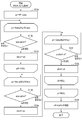
- FIG. 24 is a flowchart (flow chart) showing an example of a processing procedure from the input of the failure path by the network management device according to the embodiment of the present invention to the search of physical and equipment resources.
- FIG. 25 is a diagram showing an example of the array type of the fault location Entity applied by the network management device according to the embodiment of the present invention in a table format.
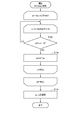
- FIG. 26 is a flowchart showing an example of a processing procedure for searching PP Entity by the network management device according to the embodiment of the present invention.
- FIG. 27 is a flowchart showing an example of a processing procedure for searching PD and PL Entity by the network management device according to the embodiment of the present invention.
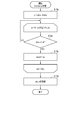
- FIG. 28 is a flowchart showing an example of a processing procedure for searching PS Entity by the network management device according to the embodiment of the present invention.
- FIG. 29 is a flowchart showing an example of a processing procedure for searching AS Entity by the network management device according to the embodiment of the present invention.
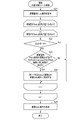
- FIG. 30 is a flowchart showing an example of a processing procedure for searching for commonly used physical resources by the network management device according to the embodiment of the present invention.
- FIG. 31 is a diagram showing an example of an array type of duplicate Entity applied by the network management device according to the embodiment of the present invention in a table format.
- FIG. 32 is a diagram showing an example of an array of failure location Entity applied by the network management device according to the embodiment of the present invention in a table format.
- FIG. 33 is a block diagram showing an example of a hardware configuration of the network management device according to the embodiment of the present invention.
- each component of the equipment layer, the physical layer, and the logical layer of the communication network is an object using a unified information object (object) (hereinafter, simply referred to as an object). Be made.
- the network management device uses the connection between the objects to identify candidates for equipment that causes a failure in the logical layer in the equipment layer and the physical layer.
- the equipment layer object contains the physical layer object.
- the network management device uses objects (Spec, Entity (information object)) based on the prior art to objectize the target NW in the logical layer, the physical layer, and the equipment layer in order from the upper layer.
- objects Spec, Entity (information object)
- the equipment layer is, for example, a building, a cable, etc.
- the building and the communication cable in the equipment layer are held as the building object and the cable object, respectively.
- the above-mentioned building is not particularly limited as long as it is a building or equipment in which a communication device is housed.
- the above cable is not particularly limited as long as it is a facility that accommodates a communication medium.
- the physical layer is, for example, a network device, a communication port, and a communication medium.
- the network device, the communication port, and the communication medium in the physical layer are held as a device object, a port object, and a medium object, respectively.
- Logical layers correspond to, for example, point objects, line or face objects.
- the place where communication occurs in the logical layer or the end thereof is held as a point object, and the communication between the point objects and the communicable range between the point objects are held as line or surface objects, respectively.
- the physical layer and the equipment layer may be referred to as a physical layer and an equipment layer in a narrow sense included in the physical layer in a broad sense.
- the operator specifies a plurality of line objects corresponding to the communication pass (sometimes referred to as the failure path) in which the failure has occurred, and sets the failure state.
- the network management device acquires the point objects that make up the line object specified in (2).
- the network management device repeatedly searches for the point object of the lower layer of the point object acquired in (3), and interrupts the process when the point object does not exist. (5) The network management device acquires the port object possessed by the point object obtained by the time when the processing in (4) is interrupted. (6) The network management device searches for device objects and medium objects that belong to the port object acquired in (5).
- the network management device acquires a building object (in which the device object is housed) including the device object acquired in (6). (8) The network management device acquires a cable object (accommodating the medium object) including the medium object acquired in (6).
- the network management device implements the steps (3) to (8) for the plurality of line objects specified in (2), and the building object, cable object, device object, and medium object used by the line object. To get.
- the network management device retains and outputs the number of duplicate uses (multiplicity) and the objects of the corresponding equipment and physical layer.
- the network management device highlights the equipment and physical layer objects held in (10) according to their respective degree of duplication.
- FIG. 1 is a diagram showing an example of objectification of equipment layers in a network configuration applied to a network management device according to an embodiment of the present invention in a table format. As shown in FIG. 1, the configuration of the equipment layer is maintained in a unified format by applying PS (Physical Sturcture) and AS (Aggregate Section) Entity.
- PS Physical Sturcture
- AS Aggregate Section
- the Entity name in the equipment layer is divided into PS and AS.
- PS means equipment such as a containment building and a manhole.
- Various "attributes: description" related to PS are as follows. (1st) status: Attribute indicating the status of PS Entity (normal: true, failure: false) (2nd) pdList: Array of PD Entity owned by PS Entity (3rd) AsList: Array of AS Entity owned by PS Entity (4th) Position: 2D coordinates indicating the position of PS Entity
- AS (Aggregate Section) means a cable, a communication line, a cable tunnel, a service tunnel, and the like.
- Various "attributes: description" related to AS are as follows.
- FIG. 2 is a diagram showing an example of objectification of a physical layer in a network configuration applied to a network management device according to an embodiment of the present invention in a table format.
- PD Physical Device
- PP Physical Port
- PL Physical Link
- PC Physical Connector
- the Entity names in the physical layer are divided into PD, PP, PL, and PC.
- PD means a device.
- Various "attributes: description" related to PD are as follows. (1st) status: Attribute indicating PD status (normal operation: true, abnormal operation: false) (2nd)
- ppList PP array of PD (3rd) position: 2D coordinates indicating the position of PD
- PP means the communication port of the device.
- Various "attributes: description” related to PP are as follows. (1st) status: Attribute indicating the status of PP (normal operation: true, abnormal operation: false) (Second) position: Two-dimensional coordinates indicating the position of PD
- PL means the core wire of the cable.
- Various "attributes: description" related to PL are as follows. (1st) status: Attribute indicating the status of PL (normal operation: true, abnormal operation: false) (2nd) pcList: PL's array of PCs
- PC means a connector for connecting cables.
- Various "attributes: description" related to PC are as follows. (1st) status: Attribute indicating the status of the PC (normal operation: true, abnormal operation: false) (Second)
- ppList Array of PPs in the PC PD in the physical layer corresponds to the above device object, PP in the physical layer corresponds to the above port object, PL in the physical layer, PC corresponds to the above medium object. Corresponds to.
- 3 and 4 are diagrams showing an example of objectification of a logical layer in a network configuration applied to a network management device according to an embodiment of the present invention in a table format.
- the logical layer configuration is TPE (Termination Point Encapsulation), NFD (Network Fowarding Domain), TL (Topological Link), FRE (Forwarding Relationship Encapsulation) (LC (Link Connect), By applying XC (Cross (X) Connect), NC (Network Connect) Entity, it is maintained in a unified format.
- FRE Entity is divided into LC (Link Connect), XC (Cross (X) Connect), NC (Network Connect)) Entity.
- LC Link Connect
- XC Cross Connect
- NC Network Connect
- TL means connectivity between devices (within the Logical Device layer).
- Various "attributes: description" related to TL are as follows. (1st) EndPointList: TPE Entity array that composes TL Entity (2nd) status: Attribute indicating the status of TL Entity (normal operation: true, abnormal operation: false)
- NFD means the transferable range (in the Logical Device layer) in the device.
- Various "attributes: description" related to NFD are as follows. (1st) endPointList: TPE Entity array that composes NFD Entity (2nd) Status: Attribute indicating the status of NFD Entity (normal operation: true, abnormal operation: false)
- TPE means the end point of communication.
- Various "attributes: description" related to TPE are as follows.
- layerName Layer name
- the TL in the logical layer corresponds to the above line object
- the NFD in the logical layer corresponds to the above line or surface object
- the TPE in the logical layer corresponds to the above point object.
- LC of FRE means connectivity between devices (in the communication layer).
- Various "attributes: description" related to LC are as follows. (1st) endPointList: TPE Entity array that composes LC Entity (2nd) status: Attribute indicating the status of LC Entity (normal operation: true, abnormal operation: false) (Third) layerName: Layer name
- XC means connectivity within the device (in the communication layer).
- Various "attributes: description" related to XC are as follows. (1st) endPointList: TPE Entity array that composes XC Entity (2nd) status: Attribute indicating the status of XC Entity (normal operation: true, abnormal operation: false) (Third) layerName: Layer name
- NC means the end-end connectivity (within the communication layer) formed by LC and XC.
- Various "attributes: description" related to XC are as follows.
- NC in the logical layer corresponds to a communication object having a point object array in which all point objects between the start point and the end point on the logical layer are stored.
- FIG. 5 is a diagram showing an application example of a facility Entity and a physical Entity applied to the network management device according to the embodiment of the present invention. As shown in FIG. 5, the physical resource is divided into a physical layer and an equipment layer.
- the physical layers of Physical Resource are PD (NW device), PD (CTF (Cable termination Frame: optical fiber termination device), PL (core wire), PC (connector). , PP (port).
- PD (NW device), PD (CTF) have PP (port), and PCs (connectors) are attached to both ends of PL (core wire).
- the PP (port) on the PD (NW device) side is connected to the PC (connector) at one end of the PL (core wire), and the PP (port) on the PD (CTF) side is the PC (port) at the other end of the PL (core wire).
- PD (NW device) and PD (CTF) can communicate. The same applies to the connection between PDs (CTFs).
- the equipment layer of the Physical Resource has a PS (station building), a PD (NW device), a PD (CTF), and an Aggregate Section (cable).
- Aggregate Section is an object that has multiple PLs (core lines).
- PD (NW device) and PD (CTF) will be installed in the PS (station building). This enables communication between PS (station buildings). For example, the PD (CTF) in the first PS (station building) and the PD (CTF) in the second PS (station building) are connected to the PS (station building) via the Aggregate Section (cable). Communication becomes possible.
- FIG. 6 is a diagram showing an application example of a physical Entity and a logical Entity applied to the network management device according to the embodiment of the present invention.
- the Physical Resource has a physical layer
- the Logical Resource has a communication layer and a Logical Device layer.
- the Logical Device layer corresponds to an object in a lower layer with respect to the logical layer
- the physical layer corresponds to an object in a lower layer with respect to the Logical Device layer.
- the PPs of the Physical Device are connected to the PCs at one end and the other end of the PL.
- the corresponding logical layer has TPE, XC and LC
- the Logical Device layer has TPE, NFD, TL.
- an object is indicated by an arrow in a lower layer with respect to a point object in a certain layer.
- the Physical Device in the physical layer corresponds to the XC in the logical layer and the NFD in the Logical Device layer, respectively.
- the PP in the Physical Device corresponds to the TPE in the logical layer and the TPE in the Logical Device layer, respectively.
- PL in the physical layer corresponds to LC in the logical layer and TL in the Logical Device layer, respectively.
- one NC is formed by XC and LC in the logical layer.
- FIG. 7 is a diagram showing an example of objectification of a network configuration applied to a network management device according to an embodiment of the present invention.
- the equipment, physical and logical layers of the network configuration of the OTN (Optical Transport Network) network that realizes two optical rings (sometimes called rings) are shown.
- the Logical Device layer is omitted.
- TPE and FRE including TPE_OTN_1 to 4, FRE (LC) _OTN_1, 2 are provided in the first ring. ..
- TPE and FRE including TPE_OTN_5, 6 and FRE (LC) _OTN_3 are provided in the second ring.
- PP, PD and PL including PP_OTN_1 to 4, PD_OTN_1 to 4 and PL_OTN_1, 2 are provided in the first ring.
- PP, PD and PL are provided in the second ring, including PP_OTN_5, 6, PD_OTN5, 6, PL_OTN_3.
- PS and AS including PS_A to F and AS_1 to 3 are provided.
- the logical layers TPE_OTN_1 to 6 have a one-to-one correspondence with the physical layers PP_OTN_1 to 6.
- the logical layer FRE (LC) _OTN_1 to 3 have a one-to-one correspondence with the physical layer PL_OTN_1 to 3. These PL_OTN_1 to 3 have a one-to-one correspondence with AS_1 to 3 of the equipment layer.
- the physical layers PD_OTN_1 to 4 have a one-to-one correspondence with the equipment layers PS_B, C, A, and D.
- PD_OTN_5 and 6 of the physical layer correspond to PS_A and F of the equipment layer on a one-to-one basis.
- FIG. 8 is a diagram showing an example of designating a failure path in a network configuration applied to the network management device according to the embodiment of the present invention.
- FRE (LC) _OTN_1, 2 and 3 on the OTN (logical layer) have failed, as shown in Fig. 8.
- these are designated as three failure paths, and the physical resources used by these paths, such as a building, a cable, and a device cable, are searched for.
- the medium accommodated by the cable AS_2, 3 is PL_OTN_2, 3.
- FIG. 9 is a diagram showing an example of searching for a physical resource used by a failure path in a network configuration applied to a network management device according to an embodiment of the present invention.
- the physical resources used by the failure path are searched by the following (1) to (6).
- the physical resource search unit 15 searches for TPEs constituting two failure paths (FRE (LC)).
- the physical resource search unit 15 searches for the PPort (PP) corresponding to the TPE obtained in (1).
- the physical resource search unit 15 searches for the PD to which the PPort obtained in (2) belongs.
- the physical resource search unit 15 searches for the PS to which the PD obtained in (3) belongs.
- the physical resource search unit 15 searches for the PL to which the PPort obtained in (2) terminates.
- the physical resource search unit 15 searches for the AS to which the PL obtained in (5) belongs.
- FIG. 10 is a diagram showing an example of a search result of a physical resource used by a failure path in a network configuration applied to a network management device according to an embodiment of the present invention in a table format.
- the search results according to (1) to (6) above regarding the physical resources used by the failure path FRE (LC) _OTN_1, 2 and 3 shown in FIG. 9 are as follows.
- FIG. 11 is a diagram showing an example of searching for physical resources having a common failure path in the network configuration applied to the network management device according to the embodiment of the present invention.
- FIG. 12 is a diagram showing an example of a search result of equipment resources having a common failure path in the network configuration applied to the network management device according to the embodiment of the present invention in a table format.
- PS, AS, and PD that are used in duplicate by a plurality of failure paths are searched.
- PS_A and AS_2 are used by two failure paths FRE (LC) _OTN_1,2.
- FRE failure path
- degree of duplication multiplicity 2 corresponding to the number of failure paths that are the main constituents to be used is shown.
- FIG. 13 is a diagram showing a functional configuration example of the network management device according to the embodiment of the present invention.
- the network management device 10 may be configured as a computer provided with a central processing unit (CPU), a program memory, a calculation memory, and the like.
- the functions required to implement this embodiment include the equipment information registration unit 11, the Spec DB (database) 12, the Entity DB 13, the failure path Entity acquisition unit 14, and the physical. It has a resource search unit 15 and a NW configuration display unit 16. These processes will be described later.
- the equipment information registration unit 11, the failure path Entity acquisition unit 14, the physical resource search unit 15, and the NW configuration display unit 16 can be realized by causing the CPU to execute a program stored in the program memory.
- the Spec DB12 and the Entity DB13 can be realized by a storage device such as a non-volatile memory.
- the NW configuration display unit 16 can be realized by using a display device such as a liquid crystal display.
- the network management device 10 may be configured by hardware, it is a well-known computer in which a program having the procedure shown in the flowchart described later is installed via a medium or a communication line. It can also be realized by a combination of a computer and Spec DB12 and Entity DB13, or a computer having Spec DB12 and Entity DB13. Details of the hardware configuration of the network management device 10 will be described later.
- FIG. 14 is a sequence diagram showing an example of a procedure for registering equipment information by the network management device according to the embodiment of the present invention.
- This equipment information (Spec) is registered in Spec DB12, and the registration result code is returned to the management screen on the operator side.
- the registration result is returned on the display screen.
- FIG. 15 is a diagram showing an example of Spec (equipment layer and physical layer) of equipment information held by the network management device according to the embodiment of the present invention in a table format.
- attributes that are unique information such as device name or cable type are held in Spec DB 12 as information in which a Spec (Specification) class (defining an attribute indicating a characteristic) is instantiated.
- Spec Specification
- Spec DB 12 information in which Specification class (defining an attribute indicating a characteristic) is instantiated.
- the following Spec class is defined. These Specs are mainly used to display NW configurations.
- Spec name: meaning in the equipment layer is as follows.
- -PS Spec Physical Structure Specification
- PS-AS Spec Aggregate Section Specification
- AS Aggregate Section Specification
- Spec name: meaning” in the physical layer is as follows.
- -PD Spec Physical Device Specification
- PD-PP Spec Physical Port Specification
- PP-PL Spec Physical Link Specification
- PC Spec Physical Connector Specification
- FIG. 16 is a diagram showing an example of a Spec (logical layer) of equipment information held by the network management device according to the embodiment of the present invention in a table format.
- attributes unique to each layer VLAN ID (Virtual LAN IDentifier), IP address (Internet Protocol address), wavelength number, etc.) are stored in Spec DB12 as information in which each Spec class is instantiated. Will be done. Specifically, the following Spec class is defined.
- ⁇ TL Spec (Topological Link Specification): Defines unique attributes for each TL ⁇ NFD Spec (Network Forwarding Domain Specification): Defines unique attributes for each NFD ⁇ TPE Spec (Termination Point Encapsulation Specification): Unique for each TPE Define attributes ⁇ NC Spec (Network Connection Specification): Define unique attributes for each NC ⁇ LC Spec (Link Connect Specification): Define unique attributes for each LC ⁇ XC Spec (Cross (X) Connect Specification): XC Define unique attributes for each
- FIG. 17 is a diagram showing an example of using the Spec and Entity classes by the network management device according to the embodiment of the present invention.
- attributes common to layers and their values are held in Entity DB 13 as information in which the Entity class is instantiated.
- One Specification class in the Spec class is associated with n SpecCharacteristic classes and n Entity classes.
- the SpecCharacteristic class includes name, valueFrom, valueTo, and Type described later.
- the Entity class includes "status: String” and "position (int, int)".
- One Entity class corresponds to n CharacteristicValue classes (a class that is an outer class of the Entity class and stores specific characteristics in which any one of the characteristics specified in the SpecCharacteristic class is realized). Can be attached.
- the CharacteristicValue class includes CharacteristicName and Value, which will be described later.
- the attribute name unique to the layer is held in SpecDB12 as information in which the SpecCharacteristic class (external class of the Specification class) is instantiated.
- the attribute value unique to the layer is held in SpecDB12 as the information in which the CharacteristicValue class is instantiated.
- the attribute name is defined in the SpecCharacteristic class.
- FIG. 18 is a diagram showing an example of a schema of a specification table of equipment information defined by a network management device according to an embodiment of the present invention in a table format.
- the schema (column name: type) of the Specification table held in Spec DB12 is as follows (see Specification in FIG. 17).
- FIG. 19 is a diagram showing an example of a schema of a Spec Characteristic table of equipment information defined by a network management device according to an embodiment of the present invention in a table format.
- the schema (column name: type) of the SpecCharacteristic table stored in Spec DB12 is as follows (see SpecCharacteristic in FIG. 17). ⁇ Name: String ⁇ ValueFrom: int ⁇ ValueTo: int ⁇ Type: String
- FIG. 20 is a diagram showing an example of the schema of the Entity table of the equipment information defined by the network management device according to the embodiment of the present invention in a table format.
- the schema (column name: type) of the Entity table held in Entity DB13 follows the definition of Entity.
- FIG. 21 is a diagram showing an example of the schema of the CharacteristicValue table of equipment information defined by the network management device according to the embodiment of the present invention in a table format.
- the schema (column name: type) of the CharacteristicValue table held in Entity DB13 is as follows (see CharacteristicValue in FIG. 17).
- the Spec of the equipment information shown in FIGS. 15 and 16 is created as a table in Spec DB 12 in the format of Specification and Spec Characteristic shown in FIG.
- the Spec Characteristic table shown in FIG. 17 is managed as a plurality of tables by a foreign key.
- This SpecCharacteristic table has four attributes (figure): name (name of characteristic), valueFrom (upper limit of concrete value allowed by characteristic), valueTo (lower limit of concrete value allowed by characteristic), and type (type of concrete value of characteristic). 17).
- the attributes of Entity shown in FIGS. 1 to 4 are created as a table in Entity DB 13.
- Entity DB 13 For example, for PD, PP, and PS Entity (see Figures 1 and 2), a table is created with a schema consisting of two attributes consisting of states and coordinates.
- Values common to the logical layer are stored in the record of the corresponding table in Entity DB 13.
- the attribute name set in the SpecCharacteristic name attribute of the corresponding Spec is set in the CharacteristicName attribute of CharacteristicValue, and that value is the value attribute of CharacteristicValue. Is set to (see FIG. 17).
- FIG. 22 is a diagram showing an example of a configuration that functions by inputting a failure location in the network management device according to the embodiment of the present invention. As shown in FIG. 22, the equipment information registration unit 11 and the Entity DB 13 function in inputting the fault location.
- the failure path Entity acquisition unit 14 inputs the failure path from a drawing object displayed by the NW configuration display unit 16 on the display screen of the network configuration, such as a keyboard or a mouse. Multiple failure paths can be specified via the GUI (Graphical User Interface) according to the operation for.
- the failure path Entity acquisition unit 14 acquires an Entity ID unique to each Entity from the Entity DB 13 for one of the drawing objects of the specified failure path.
- the failure path Entity acquisition unit 14 accesses the Entity DB 13 by the acquired Entity ID, and acquires the Entity corresponding to the failure path (hereinafter, may be referred to as the failure path Entity).
- FIG. 23 is a diagram showing an example of a configuration that functions in physical resource search in the network management device according to the embodiment of the present invention. As shown in FIG. 23, the Entity DB 13, the failure path Entity acquisition unit 14, and the physical resource search unit 15 function in the physical resource search.
- FIG. 24 is a flowchart showing an example of a processing procedure from inputting a failure path to searching for physical and equipment resources by the network management device according to the embodiment of the present invention.
- the physical resource search unit 15 acquires the failure path Entity from the Entity DB 13 corresponding to the failure path Entity ID [i] (S11). S11 corresponds to the input of the failure path.
- the physical resource search unit 15 acquires the PP Entity corresponding to the failure path Entity acquired in S11 from the Entity DB 13 (S12).
- the physical resource search unit 15 acquires PD and PL Entity having the PP Entity acquired in S12 from the Entity DB 13 (S13).
- the physical resource search unit 15 acquires a PS Entity having the PD Entity acquired in S13 from the Entity DB 13 (S14).
- the physical resource search unit 15 acquires an AS Entity having the PL Entity acquired in S13 from the Entity DB 13 (S15).
- the processes S12 to S15 correspond to the physical resource search used by the failure path. Details of the processing of S12 to S15 will be described later.
- FIG. 25 is a diagram showing an example of the array type of the fault location Entity applied by the network management device according to the embodiment of the present invention in a table format. Failure location Failure path of Entity array
- the types of Entity name, PS EntityList (array), AS EntityList (array) and PD EntityList (array) are as follows.
- FIG. 26 is a flowchart showing an example of a processing procedure for searching a PP Entity by the network management device according to the embodiment of the present invention.
- the physical resource search unit 15 acquires the endPointList of the failure path Entity (LC or NC) from the Entity DB 13 (S12a).
- the failure path Entity (XC) is specified by the input operation by the operator, and the physical resource search unit 15 may acquire the endPointList of the failure path Entity (XC) from the Entity DB 13.
- the physical resource search unit 15 acquires an instance of TPEEntity from EntityDB13 from the index i of the endPointList array, and stores the acquired instance in the tpe instance (instance of TPEEntity) variable e (S12b).
- the physical resource search unit 15 acquires an instance of PP Entity (sometimes referred to as a PP instance) from the ppRefList [i] array of the tpe instance variable, and obtains this acquired instance from Entity DB 13. It is stored in pPort (pp instance variable) (S12e). When the above condition is satisfied after S12d, or after S12e, the physical resource search unit 15 returns the pPort to S13 (S12f), and the process ends.
- PP Entity sometimes referred to as a PP instance
- pPort pp instance variable
- FIG. 27 is a flowchart showing an example of a processing procedure for searching PD and PL Entity by the network management device according to the embodiment of the present invention.
- the physical resource search unit 15 stores the PP Entity searched in S12 in the pp instance variable (S13a).
- the physical resource search unit 15 extracts one record of the PP Entity array (pd.ppList array (see FIG. 2)) of the PD Entity from the Entity DB 13 and stores it in the pd instance (PD Entity instance) variable.
- the physical resource search unit 15 determines whether or not the PP instance searched in S12 is included in the pd.ppList array (S13b). If Yes in S13b, the physical resource search unit 15 stores the PD instance having the PP instance in the pdList array (S13c). If No in S13b, the process moves to S13b related to another record in the pd.ppList array.
- the physical resource search unit 15 sets one record of the PPEntity array (pc.ppList array (see FIG. 2)) of the PCEntity as an Entity. It is taken out from DB13 and stored in the pc instance (instance of PCEntity) variable.
- the physical resource search unit 15 determines whether or not the pp instance is included in the pc.ppList array (S13d). If Yes in S13d, the physical resource search unit 15 stores the PC instance having the PP instance in the pcList array (S13e). If No in S13d, the process moves to S13d related to another record in the pc.ppList array.
- the physical resource search unit 15 extracts one record of the PCEntity array (pl.pcList array (see FIG. 2)) of the PLEntity from the EntityDB13 and sets it as a pl instance (PLEntity instance) variable. Store.
- the physical resource search unit 15 determines whether or not the pc instance is included in the pl.pcList array (S13f). If Yes in S13f, the physical resource search unit 15 stores the PL instance having the PC instance in the plList array (S13g). If No in S13f, the process moves to S13f related to another record in the pl.pcList array.
- the physical resource search unit 15 returns the pdList stored in S13c to S14 and S16, and returns the plList stored in S13g to S15 (S13h). ), The process ends.
- FIG. 28 is a flowchart showing an example of a processing procedure for searching a PS Entity by the network management device according to the embodiment of the present invention.
- the physical resource search unit 15 retrieves one record of the pdList searched in S13 and stores it in the pd instance variable.
- the physical resource search unit 15 extracts one record of the PD Entity array (ps.pdList array (see FIG. 1)) of the PS Entity from the Entity DB 13 and stores it in the ps instance (PS Entity instance) variable.
- the physical resource search unit 15 determines whether or not the pd instance is included in the ps.pdList array (S14a). If Yes in S14a, the physical resource search unit 15 stores the PS instance having the PD instance in the psList array (S14b). If No in S14b, the process moves to S14a related to another record in the ps.pdList array.
- FIG. 29 is a flowchart showing an example of a processing procedure for searching an AS Entity by the network management device according to the embodiment of the present invention.
- the physical resource search unit 15 stores the plList Entity searched in S13 in the pl instance variable (S15a).
- the physical resource search unit 15 extracts one record of the PL Entity array (as.plList array) of the AS Entity from the Entity DB 13 and stores it in the as instance (AS Entity instance) variable.
- the physical resource search unit 15 determines whether or not the pl instance is included in the as.plList array (S15b). If Yes in S15b, the physical resource search unit 15 stores the AS instance having the PL instance in the asList array (S15c). If No in S15c, the process moves to S15b relating to another record in the as.plList array.
- FIG. 30 is a flowchart showing an example of a processing procedure for searching for commonly used physical resources by the network management device according to the embodiment of the present invention.
- the physical resource search unit 15 acquires the failure location Entity array stored in S16 from the Entity DB 13 (S21).
- the following S22 to 24 are repeated until the condition that the element i of the array to be processed is empty in the failure location Entity array is satisfied.
- the physical resource search unit 15 has the Entity determined to be the same element and the multiplicity related to this Entity.
- the stored duplicate Entity array is returned and the process ends. As a result, the physical resources commonly used by the plurality of failure paths are searched.
- FIG. 31 is a diagram showing an example of an array type of duplicate Entity applied by the network management device according to the embodiment of the present invention in a table format.
- the types of duplicate Entity and multiplicity of duplicate Entity array are as follows.
- FIG. 32 is a diagram showing an example of an array of failure location Entity applied by the network management device according to the embodiment of the present invention in a table format.
- the failure path Entity name, PS EntityList, AS EntityList, and PD EntityList related to the array index "1" in the failure location Entity array shown in FIG. 32 are as follows.
- Failure path Entity name FRE_LC (OTN) _2
- PS EntityList PS_A
- PS_D AS EntityList: AS_2
- PD EntityList PD_OTN_3, PD_OTN_4
- the failure path Entity name, PSEntityList, ASEntityList, and PDEntityList related to the array index "2" in the failure location Entity array shown in FIG. 32 are as follows.
- Failure path Entity name FRE_LC (OTN) _3
- PS EntityList PS_A
- PS_F AS EntityList AS_2
- PD EntityList PD_OTN_5
- PS_A and AS_2 are duplicated between the arrays indexes “1” and “2" (see a and b in FIG. 32), and these are multiple failure paths (see a and b in FIG. 32). It corresponds to the physical resource commonly used by FRE_LC (OTN) _2, FRE_LC (OTN) _3).
- PDEntityList does not overlap between the arrays indexes “1” and “2” (see c in FIG. 32).
- the NW configuration display unit 16 distinguishes the drawing object corresponding to the physical resource searched by the physical resource search unit 15 in S12 to S15 from the drawing object corresponding to another resource in the network configuration. For example, colors are distinguished and highlighted on the screen.
- the NW configuration display unit 16 acquires all Entity of the equipment layer and the physical layer in the network configuration from Entity DB13, and acquires Spec information corresponding to all Entity as a Spec array from SpecDB12.
- the NW configuration display unit 16 acquires two-dimensional coordinates (see FIGS. 1 to 3) indicating the positions of each Entity from the Entity DB 13, and draws the equipment layer and the physical layer at the positions corresponding to the acquired coordinates on the screen. Display the object.
- the drawing based on the coordinate information of the object is also described in the Japanese Patent Application No. 2018-034981.
- the NW configuration display unit 16 acquires the two-dimensional coordinates indicating the positions of the PD, PS, and AS Entity stored in the failure location Entity array in S16 among the above two-dimensional coordinates, and the drawing object at this position. Is highlighted in red, for example, to distinguish it from other objects.
- the NW configuration display unit 16 distinguishes the drawing objects corresponding to the physical resources (physical layer and equipment layer) used by the plurality of failure paths among the drawing objects from other objects. As such, it can be highlighted in blue, for example. Further, the highlighted color may be distinguished according to the degree of overlap.
- FIG. 33 is a block diagram showing an example of the hardware configuration of the network management device according to the embodiment of the present invention.
- the network management device 10 according to the above embodiment is composed of, for example, a server computer or a personal computer, and is a hardware processor 111A such as a CPU. Has. Then, the program memory 111B, the data memory 112, the input / output interface 113, and the communication interface 114 are connected to the hardware processor 111A via the bus 120. ..
- the communication interface 114 includes, for example, one or more wireless communication interface units, and enables information to be transmitted / received to / from the communication network NW.
- the wireless interface for example, an interface that employs a low-power wireless data communication standard such as a wireless LAN (Local Area Network) is used.
- An input device 20 (device) for an operator and an output device 30 attached to the network management device 10 are connected to the input / output interface 113.
- the input / output interface 113 captures operation data input by an operator through an input device 20 such as a keyboard, touch panel, touchpad, mouse, etc., and outputs data as liquid crystal or organic EL (Electro).
- a process of outputting to an output device 30 including a display device using Luminescence) or the like and displaying the data is performed.
- a device built in the network management device 10 may be used, and other information capable of communicating with the network management device 10 via the network NW. Terminal input and output devices may be used.
- the program memory 111B is a non-volatile memory (non-volatile memory) that can be written and read at any time, such as an HDD (Hard Disk Drive) or an SSD (Solid State Drive), as a non-temporary tangible storage medium. It is used in combination with a non-volatile memory such as a ROM (Read Only Memory), and stores programs necessary for executing various control processes according to one embodiment.
- non-volatile memory non-volatile memory
- HDD Hard Disk Drive
- SSD Solid State Drive
- ROM Read Only Memory
- the data memory 112 is used as a tangible storage medium, for example, in combination with the above-mentioned non-volatile memory and a volatile memory such as RAM (RandomAccessMemory), and various processes are performed. It is used to store various data acquired and created in the process.
- RAM RandomAccessMemory
- the network management device 10 has the equipment information registration unit 11, Spec DB12, Entity DB13, failure path Entity acquisition unit 14, and physical as the processing function unit by software. It can be configured as a data processing device having a resource search unit 15 and a NW configuration display unit 16.
- Spec DB12 and EntityDB13 can be configured by using the data memory 112 shown in FIG. 33.
- these areas are not indispensable configurations in the network management device 10, for example, an external storage medium such as a USB (Universal Serial Bus) memory, a database server arranged in a cloud, or the like. It may be an area provided in the storage device of.
- an external storage medium such as a USB (Universal Serial Bus) memory
- a database server arranged in a cloud or the like. It may be an area provided in the storage device of.
- the processing function units in each of the equipment information registration unit 11, the failure path Entity acquisition unit 14, the physical resource search unit 15, and the NW configuration display unit 16 all use the program stored in the program memory 111B as the hardware processor. It can be realized by reading and executing by 111A. Part or all of these processing function units may be in various other formats, including integrated circuits such as integrated circuits (ASICs (Application Specific Integrated Circuits)) or FPGAs (Field-Programmable Gate Arrays) for specific applications. It may be realized.
- ASICs Application Specific Integrated Circuits
- FPGAs Field-Programmable Gate Arrays
- the network management device searches for objects in the physical layer and the equipment layer corresponding to the failure path when a failure occurs on the logical layer of the communication network. Therefore, the candidate equipment that causes the failure can be identified.
- the network management device can also search for objects in the physical layer and the logical layer that are commonly used by the plurality of failure paths when a failure occurs in a plurality of paths.
- the method described in each embodiment is a program (software means) that can be executed by a computer (computer), for example, a magnetic disk (floppy (registered trademark) disk (Floppy disk), hard disk, etc.), an optical disk, etc. It can be stored in a recording medium such as (optical disc) (CD-ROM, DVD, MO, etc.), semiconductor memory (ROM, RAM, Flash memory, etc.), or transmitted and distributed by a communication medium.
- the program stored on the medium side also includes a setting program for configuring the software means (including not only the execution program but also the table and the data structure) to be executed by the computer in the computer.
- a computer that realizes this device reads a program recorded on a recording medium, constructs software means by a setting program in some cases, and executes the above-mentioned processing by controlling the operation by the software means.
- the recording medium referred to in the present specification is not limited to distribution, and includes storage media such as magnetic disks and semiconductor memories provided in devices connected inside a computer or via a network.
- the present invention is not limited to the above embodiment, and can be variously modified at the implementation stage without departing from the gist thereof.
- each embodiment may be carried out in combination as appropriate, and in that case, the combined effect can be obtained.
- the above-described embodiment includes various inventions, and various inventions can be extracted by a combination selected from a plurality of disclosed constituent requirements. For example, even if some constituent requirements are deleted from all the constituent requirements shown in the embodiment, if the problem can be solved and the effect is obtained, the configuration in which the constituent requirements are deleted can be extracted as an invention.
Landscapes
- Engineering & Computer Science (AREA)
- Computer Networks & Wireless Communication (AREA)
- Signal Processing (AREA)
- Data Exchanges In Wide-Area Networks (AREA)
Abstract
一実施形態に係るネットワーク管理装置は、ネットワーク構成の論理レイヤに関する情報オブジェクトと物理レイヤに関する情報オブジェクトと当該物理レイヤに関する情報オブジェクトが収容されるオブジェクトである設備レイヤに関する情報オブジェクトとの対応関係を示す情報を格納する格納装置と、前記ネットワーク構成の論理レイヤにおける障害の発生経路に関する情報オブジェクトを、前記格納装置から取得する取得部と、前記格納装置に格納される前記設備レイヤに関する情報オブジェクトのうち、前記取得部により取得された、前記障害の発生経路に関する情報オブジェクトに対応付けられる前記設備レイヤおよび前記物理レイヤに関する情報オブジェクトを、障害原因となる設備の候補として検索する検索部とを有する。
Description
本発明の実施形態は、ネットワーク管理装置、方法およびプログラムに関する。
通信ネットワーク(network)によるサービス(service)を実現する物理レイヤ上のビル(building)、通信ケーブル(cable)、通信装置、または通信媒体に障害を疑似的に発生させ、この障害がサービスへ及ぼす影響をシミュレーション(simulation)する際、サービス、NWの種別に依らず、同一の方法でサービスへ及ぼす影響を特定する技術がある(例えば非特許文献1を参照)。
ネットワーク障害が及ぼすサービス影響把握方式の検討(A Study on Method of Visualization for Multiple Network Structure)(ICM研究会2019年3月)
上記の非特許文献1に開示される技術は、論理レイヤ(layer)上の伝送レイヤ、サービスレイヤなどで起きた障害を引き起こした、物理レイヤ上の箇所の候補を特定する手段を提供していない。
この発明は、上記事情に着目してなされたもので、その目的とするところは、通信ネットワークの論理レイヤ上で発生した障害原因となる設備の候補を特定することができるようにしたネットワーク管理装置、方法およびプログラムを提供することにある。
本発明の一態様に係るネットワーク管理装置は、ネットワーク構成の論理レイヤに関する情報オブジェクトと物理レイヤに関する情報オブジェクトと当該物理レイヤに関する情報オブジェクトが収容されるオブジェクトである設備レイヤに関する情報オブジェクトとの対応関係を示す情報を格納する格納装置と、前記ネットワーク構成の論理レイヤにおける障害の発生経路に関する情報オブジェクトを、前記格納装置から取得する取得部と、前記格納装置に格納される前記設備レイヤに関する情報オブジェクトのうち、前記取得部により取得された、前記障害の発生経路に関する情報オブジェクトに対応付けられる前記設備レイヤおよび前記物理レイヤに関する情報オブジェクトを、障害原因となる設備の候補として検索する検索部とを備える。
本発明の一態様に係るネットワーク管理方法は、ネットワーク構成の論理レイヤに関する情報オブジェクトと物理レイヤに関する情報オブジェクトと当該物理レイヤに関する情報オブジェクトが収容されるオブジェクトである設備レイヤに関する情報オブジェクトとの対応関係が示される情報が格納される格納装置を有するネットワーク管理装置により行なわれるネットワーク管理方法であって、前記ネットワーク構成の論理レイヤにおける障害の発生経路に関する情報オブジェクトを、前記格納装置から取得することと、前記格納装置に格納される前記設備レイヤに関する情報オブジェクトのうち、前記取得された、前記障害の発生経路に関する情報オブジェクトに対応付けられる前記設備レイヤおよび前記物理レイヤに関する情報オブジェクトを、障害原因となる設備の候補として検索することと、を備える。
本発明によれば、通信ネットワークの論理レイヤ上で発生した障害原因となる設備の候補を特定することができる。
以下、図面を参照しながら、この発明に係わる一実施形態を説明する。
本発明の一実施形態に係るネットワーク管理装置では、通信ネットワークの設備レイヤ、物理レイヤおよび論理レイヤの各構成要素が、統一された情報オブジェクト(object)(以下、単にオブジェクトと称する)を用いてオブジェクト化される。
また、ネットワーク管理装置は、各オブジェクト間のつながりを用いて、論理レイヤで発生した障害原因となる設備の候補を設備レイヤおよび物理レイヤにて特定する。設備レイヤのオブジェクトには、物理レイヤのオブジェクトが収容される。
これにより、プロトコル(protocol)、媒体種別の異なる複数レイヤにより構成されたネットワークで発生した障害原因となる設備の候補が特定される。
本発明の一実施形態に係るネットワーク管理装置では、通信ネットワークの設備レイヤ、物理レイヤおよび論理レイヤの各構成要素が、統一された情報オブジェクト(object)(以下、単にオブジェクトと称する)を用いてオブジェクト化される。
また、ネットワーク管理装置は、各オブジェクト間のつながりを用いて、論理レイヤで発生した障害原因となる設備の候補を設備レイヤおよび物理レイヤにて特定する。設備レイヤのオブジェクトには、物理レイヤのオブジェクトが収容される。
これにより、プロトコル(protocol)、媒体種別の異なる複数レイヤにより構成されたネットワークで発生した障害原因となる設備の候補が特定される。
次に、本発明の一実施形態に係るネットワーク管理装置の概要について、下記の(1)~(11)にて説明する。
(1) ネットワーク管理装置は、従来技術に基づくオブジェクト(Spec, Entity(情報オブジェクト))により、対象となるNWを上位レイヤから順に論理レイヤ、物理レイヤおよび設備レイヤにてオブジェクト化する。
(1) ネットワーク管理装置は、従来技術に基づくオブジェクト(Spec, Entity(情報オブジェクト))により、対象となるNWを上位レイヤから順に論理レイヤ、物理レイヤおよび設備レイヤにてオブジェクト化する。
設備レイヤは例えばビル、ケーブルなどである。本実施形態では、設備レイヤにおけるビル、通信ケーブルがビルオブジェクト、ケーブルオブジェクトとしてそれぞれ保持される。上記のビルは通信装置が収容される建物または設備であれば特に限られない。また、上記のケーブルは通信媒体が収容される設備であれば特に限られない。
物理レイヤは、例えばネットワーク装置、通信ポート(port)、通信媒体である。本実施形態では、物理レイヤにおけるネットワーク装置、通信ポート、通信媒体は、装置オブジェクト、ポートオブジェクト、媒体オブジェクトとしてそれぞれ保持される。
論理レイヤは例えば点オブジェクト、線又は面オブジェクトに対応する。本実施形態では、論理レイヤにおける通信の発生箇所又はその終端が点オブジェクトとして保持され、この点オブジェクト間の通信と、点オブジェクト間の通信可能範囲とが、線又は面オブジェクトとしてそれぞれ保持される。
なお、上記の物理レイヤおよび設備レイヤは、広義の物理レイヤに含まれる狭義の物理レイヤおよび設備レイヤと称してもよい。
なお、上記の物理レイヤおよび設備レイヤは、広義の物理レイヤに含まれる狭義の物理レイヤおよび設備レイヤと称してもよい。
(2) オペレータ(operator)は、障害が発生した通信パス(communication pass)(障害パスと称されることがある)に対応する複数の線オブジェクトを指定して、故障状態を設定する。
(3) ネットワーク管理装置は、(2)で指定された線オブジェクトを構成する点オブジェクトを取得する。
(4) ネットワーク管理装置は、(3)で取得された点オブジェクトが有する、下位レイヤの点オブジェクトを繰り返し検索し、点オブジェクトが存在しない場合に処理を中断する。
(5) ネットワーク管理装置は、(4)での処理中断時までに得られた点オブジェクトが有するポートオブジェクトを取得する。
(6) ネットワーク管理装置は、(5)で取得されたポートオブジェクトに属する装置オブジェクトおよび媒体オブジェクトを検索する。
(5) ネットワーク管理装置は、(4)での処理中断時までに得られた点オブジェクトが有するポートオブジェクトを取得する。
(6) ネットワーク管理装置は、(5)で取得されたポートオブジェクトに属する装置オブジェクトおよび媒体オブジェクトを検索する。
(7) ネットワーク管理装置は、(6)で取得された装置オブジェクトを含む(装置オブジェクトが収容される)ビルオブジェクトを取得する。
(8) ネットワーク管理装置は、(6)で取得された媒体オブジェクトを含む(媒体オブジェクトが収容される)ケーブルオブジェクトを取得する。
(8) ネットワーク管理装置は、(6)で取得された媒体オブジェクトを含む(媒体オブジェクトが収容される)ケーブルオブジェクトを取得する。
(9) ネットワーク管理装置は、(2)で指定された複数の線オブジェクトについて(3)~(8)の手順を実施し、線オブジェクトにより利用されるビルオブジェクト、ケーブルオブジェクト、装置オブジェクトおよび媒体オブジェクトを取得する。
(10) 線オブジェクトにより共通して利用されるビルオブジェクト、ケーブルオブジェクト、装置オブジェクトおよび媒体オブジェクトについて、他の線オブジェクトにより重複利用されるものがある。ネットワーク管理装置は、この重複利用の数(重複度)と、該当する設備、物理レイヤのオブジェクトを保持し、出力する。
(11)ネットワーク管理装置は、(10)で保持した設備および物理レイヤのオブジェクトを、それぞれの重複度に応じて強調表示する。
次に、ネットワーク構成のオブジェクト化について説明する。ここでは、設備レイヤのオブジェクト化の方法について説明する。このオブジェクト化については、例えば日本国特願2018-196853明細書およびPCT/JP2019/040978明細書にも記載されている。
図1は、本発明の一実施形態に係るネットワーク管理装置に適用されるネットワーク構成における設備レイヤのオブジェクト化の一例を表形式で示す図である。
図1に示されるように、設備レイヤの構成は、PS(Physical Sturcture),AS(Aggregate Section) Entityが適用されることにより、統一した形式で保持される。
図1に示されるように、設備レイヤの構成は、PS(Physical Sturcture),AS(Aggregate Section) Entityが適用されることにより、統一した形式で保持される。
図1に示されるように、設備レイヤにおけるEntity名は、PSおよびASに区分される。
図1に示されるように、PSは収容ビル、マンホール(manhole)などの設備を意味する。PSに係る各種の「属性:説明」は以下のとおりである。
(1つ目)status:PS Entityの状態を示す属性(正常:true,故障:false)
(2つ目)pdList:PS Entityが持つPD Entityの配列
(3つ目)AsList:PS Entityが持つAS Entityの配列
(4つ目)Position:PS Entityの位置を示す2次元座標
図1に示されるように、PSは収容ビル、マンホール(manhole)などの設備を意味する。PSに係る各種の「属性:説明」は以下のとおりである。
(1つ目)status:PS Entityの状態を示す属性(正常:true,故障:false)
(2つ目)pdList:PS Entityが持つPD Entityの配列
(3つ目)AsList:PS Entityが持つAS Entityの配列
(4つ目)Position:PS Entityの位置を示す2次元座標
図1に示されるように、AS(Aggregate Section)は、ケーブル、通信管路(communication line)、とう道(洞道)(cable tunnel/service tunnel)などを意味する。ASに係る各種の「属性:説明」は以下のとおりである。
(1つ目)status:AS Entityの状態を示す属性(正常:true,故障:false)
(2つ目)plList:AS Entityが持つPL Entityの配列
(3つ目)position:ASの位置を示す2次元座標
設備レイヤのPSは上記のビルオブジェクトに対応し、設備レイヤのASは上記のケーブルオブジェクトに対応する。
(2つ目)plList:AS Entityが持つPL Entityの配列
(3つ目)position:ASの位置を示す2次元座標
設備レイヤのPSは上記のビルオブジェクトに対応し、設備レイヤのASは上記のケーブルオブジェクトに対応する。
次に物理レイヤのオブジェクト化について説明する。
図2は、本発明の一実施形態に係るネットワーク管理装置に適用されるネットワーク構成における物理レイヤのオブジェクト化の一例を表形式で示す図である。
図2に示されるように、物理レイヤの構成には、PD(Physical Device), PP(Physical Port),PL(Physical Link),PC(Physical Connector) Entityが適用されることにより、統一した形式で保持される。
図2は、本発明の一実施形態に係るネットワーク管理装置に適用されるネットワーク構成における物理レイヤのオブジェクト化の一例を表形式で示す図である。
図2に示されるように、物理レイヤの構成には、PD(Physical Device), PP(Physical Port),PL(Physical Link),PC(Physical Connector) Entityが適用されることにより、統一した形式で保持される。
図2に示されるように、物理レイヤにおけるEntity名は、PD, PP, PL, PCに区分される。
図2に示されるように、PDは装置を意味する。PDに係る各種の「属性:説明」は以下のとおりである。
(1つ目)status:PDの状態を示す属性(正常動作:true,異常動作:false)
(2つ目)ppList:PDが持つPPの配列
(3つ目)position:PDの位置を示す2次元座標
図2に示されるように、PDは装置を意味する。PDに係る各種の「属性:説明」は以下のとおりである。
(1つ目)status:PDの状態を示す属性(正常動作:true,異常動作:false)
(2つ目)ppList:PDが持つPPの配列
(3つ目)position:PDの位置を示す2次元座標
PPは装置が有する通信ポートを意味する。PPに係る各種の「属性:説明」は以下のとおりである。
(1つ目)status:PPの状態を示す属性(正常動作:true,異常動作:false)
(2つ目)position:PDの位置を示す2次元座標
(1つ目)status:PPの状態を示す属性(正常動作:true,異常動作:false)
(2つ目)position:PDの位置を示す2次元座標
PLはケーブルの心線を意味する。PLに係る各種の「属性:説明」は以下のとおりである。
(1つ目)status:PLの状態を示す属性(正常動作:true,異常動作:false)
(2つ目)pcList:PLが持つPCの配列
(1つ目)status:PLの状態を示す属性(正常動作:true,異常動作:false)
(2つ目)pcList:PLが持つPCの配列
PCはケーブルの接続用コネクタ(connector)を意味する。PCに係る各種の「属性:説明」は以下のとおりである。
(1つ目)status:PCの状態を示す属性(正常動作:true,異常動作:false)
(2つ目)ppList:PCが有するPPの配列
物理レイヤにおけるPDは上記の装置オブジェクトに対応し、物理レイヤにおけるPPは上記のポートオブジェクトに対応し、物理レイヤにおけるPL, PCは上記の媒体オブジェクトに対応する。
(1つ目)status:PCの状態を示す属性(正常動作:true,異常動作:false)
(2つ目)ppList:PCが有するPPの配列
物理レイヤにおけるPDは上記の装置オブジェクトに対応し、物理レイヤにおけるPPは上記のポートオブジェクトに対応し、物理レイヤにおけるPL, PCは上記の媒体オブジェクトに対応する。
次に論理レイヤのオブジェクト化について説明する。
図3および図4は、本発明の一実施形態に係るネットワーク管理装置に適用されるネットワーク構成における論理レイヤのオブジェクト化の一例を表形式で示す図である。
図3および図4に示されるように、論理レイヤの構成は、TPE(Termination Point Encapsulation),NFD(Network Fowarding Domain),TL(Topological Link),FRE(Forwarding Relationship Encapsulation)(LC(Link Connect),XC(Cross(X) Connect),NC(Network Connect)) Entityが適用されることにより、統一した形式で保持される。
図3および図4は、本発明の一実施形態に係るネットワーク管理装置に適用されるネットワーク構成における論理レイヤのオブジェクト化の一例を表形式で示す図である。
図3および図4に示されるように、論理レイヤの構成は、TPE(Termination Point Encapsulation),NFD(Network Fowarding Domain),TL(Topological Link),FRE(Forwarding Relationship Encapsulation)(LC(Link Connect),XC(Cross(X) Connect),NC(Network Connect)) Entityが適用されることにより、統一した形式で保持される。
図4に示されるように、FRE Entity は、LC(Link Connect),XC(Cross(X) Connect),NC(Network Connect)) Entityに区分される。
TLは装置間の接続性(Logical Deviceレイヤ内)を意味する。TLに係る各種の「属性:説明」は以下のとおりである。
(1つ目)EndPointList:TL Entityを構成するTPE Entity配列
(2つ目)status:TL Entityの状態を示す属性(正常動作:true,異常動作:false)
(1つ目)EndPointList:TL Entityを構成するTPE Entity配列
(2つ目)status:TL Entityの状態を示す属性(正常動作:true,異常動作:false)
NFDは装置内の転送可能範囲(Logical Deviceレイヤ内)を意味する。NFDに係る各種の「属性:説明」は以下のとおりである。
(1つ目)endPointList:NFD Entityを構成するTPE Entity配列
(2つ目)Status:NFD Entityの状態を示す属性(正常動作:true,異常動作:false
(1つ目)endPointList:NFD Entityを構成するTPE Entity配列
(2つ目)Status:NFD Entityの状態を示す属性(正常動作:true,異常動作:false
TPEは通信の終端点を意味する。TPEに係る各種の「属性:説明」は以下のとおりである。
(1つ目)tpeRefList:対応する下位レイヤのTPE Entityを持つTPE Entity配列(実施例では配列数1)
(2つ目)ppRefList:TPE Entityに対応するPP Entity配列(実施例では配列数1)
(3つ目)status:TPE Entityの状態を示す属性(正常動作:true,異常動作:false)
(4つ目)layerName:レイヤ名
論理レイヤにおけるTLは上記の線オブジェクトに対応し、論理レイヤにおけるNFDは上記の線または面オブジェクトに対応し、論理レイヤにおけるTPEは上記の点オブジェクトに対応する。
(1つ目)tpeRefList:対応する下位レイヤのTPE Entityを持つTPE Entity配列(実施例では配列数1)
(2つ目)ppRefList:TPE Entityに対応するPP Entity配列(実施例では配列数1)
(3つ目)status:TPE Entityの状態を示す属性(正常動作:true,異常動作:false)
(4つ目)layerName:レイヤ名
論理レイヤにおけるTLは上記の線オブジェクトに対応し、論理レイヤにおけるNFDは上記の線または面オブジェクトに対応し、論理レイヤにおけるTPEは上記の点オブジェクトに対応する。
FREのLCは装置間の接続性(通信レイヤ内)を意味する。LCに係る各種の「属性:説明」は以下のとおりである。
(1つ目)endPointList:LC Entityを構成するTPE Entity配列
(2つ目)status:LC Entityの状態を示す属性(正常動作:true,異常動作:false)
(3つ目)layerName:レイヤ名
(1つ目)endPointList:LC Entityを構成するTPE Entity配列
(2つ目)status:LC Entityの状態を示す属性(正常動作:true,異常動作:false)
(3つ目)layerName:レイヤ名
XCは装置内の接続性(通信レイヤ内)を意味する。XCに係る各種の「属性:説明」は以下のとおりである。
(1つ目)endPointList:XC Entityを構成するTPE Entity配列
(2つ目)status:XC Entityの状態を示す属性(正常動作:true,異常動作:false)
(3つ目)layerName:レイヤ名
(1つ目)endPointList:XC Entityを構成するTPE Entity配列
(2つ目)status:XC Entityの状態を示す属性(正常動作:true,異常動作:false)
(3つ目)layerName:レイヤ名
NCはLC,XCによって形成されるEnd-Endの接続性(通信レイヤ内) を意味する。XCに係る各種の「属性:説明」は以下のとおりである。
(1つ目)endPointList:LC,XCを構成するTPE Entity配列
(2つ目)status:NC Entityの状態を示す属性(正常動作:true,異常動作:false)
(3つ目)userList:加入者名を保持する文字列配列または,加入者名を取得するIF(interface)のURL(Uniform Resource Locator)
(4つ目)layerName:レイヤ名
論理レイヤにおけるLCおよびXCは上記の線または面オブジェクトに対応する。また、論理レイヤにおけるNCは、論理レイヤ上の始点と終点との間の全ての点オブジェクトが格納される点オブジェクト配列を有する通信オブジェクトに対応する。
(1つ目)endPointList:LC,XCを構成するTPE Entity配列
(2つ目)status:NC Entityの状態を示す属性(正常動作:true,異常動作:false)
(3つ目)userList:加入者名を保持する文字列配列または,加入者名を取得するIF(interface)のURL(Uniform Resource Locator)
(4つ目)layerName:レイヤ名
論理レイヤにおけるLCおよびXCは上記の線または面オブジェクトに対応する。また、論理レイヤにおけるNCは、論理レイヤ上の始点と終点との間の全ての点オブジェクトが格納される点オブジェクト配列を有する通信オブジェクトに対応する。
次に、設備Entityおよび物理Entityの適用事例について説明する。図5は、本発明の一実施形態に係るネットワーク管理装置に適用される設備Entityおよび物理Entityの適用事例を示す図である。
図5に示されるように、Physical Resourceは、物理レイヤと設備レイヤに区分される。
図5に示されるように、Physical Resourceは、物理レイヤと設備レイヤに区分される。
図5に示された例では、Physical Resourceの物理レイヤは、PD(NW装置)、PD(CTF(Cable termination Frame:光ファイバ(optical fiber)終端装置)、PL(心線)、PC(コネクタ)、PP(ポート)を有する。PD(NW装置)、PD(CTF)は、PP(ポート)を備え、PL(心線)の両端にはPC(コネクタ)が取り付けられる。
PD(NW装置)側のPP(ポート)がPL(心線)の一端のPC(コネクタ)に接続され、PD(CTF)側のPP(ポート)がPL(心線)の他端のPC(コネクタ)に接続されることで、PD(NW装置)とPD(CTF)が通信可能となる。PD(CTF)同士の接続についても同様である。
図5に示された例では、Physical Resourceの設備レイヤは、PS(局ビル)、PD(NW装置)、PD(CTF)、Aggregate Section(ケーブル)を有する。
Aggregate SectionはPL(心線)を複数有するオブジェクトである。
Aggregate SectionはPL(心線)を複数有するオブジェクトである。
PS(局ビル)内にはPD(NW装置)、PD(CTF)が設けられる。これにより、PS(局ビル)間が通信可能となる。例えば、1つ目のPS(局ビル)内のPD(CTF)と、2つ目のPS(局ビル)内のPD(CTF)とが、Aggregate Section(ケーブル)を介してPS(局ビル)通信可能となる。
次に、物理Entityおよび論理Entityの適用事例について説明する。図6は、本発明の一実施形態に係るネットワーク管理装置に適用される物理Entityおよび論理Entityの適用事例を示す図である。
図6に示された例では、Physical Resourceは物理レイヤを有し、Logical Resourceは、通信レイヤとLogical Deviceレイヤとを有する。Logical Deviceレイヤは、論理レイヤに対する下位レイヤでのオブジェクトに対応し、物理レイヤは、Logical Deviceレイヤに対する下位レイヤでのオブジェクトに対応する。図6に示された例では、物理レイヤでは、Physical DeviceのPP同士が、PLの一端および他端のPCと接続される。
対応する論理レイヤは、TPE, XCおよびLCを有し、Logical DeviceレイヤはTPE,NFD,TLを有する。図6では、あるレイヤでの点オブジェクトに対する下位レイヤにオブジェクトが矢印で示される。
図6に示された例では、Physical Resourceは物理レイヤを有し、Logical Resourceは、通信レイヤとLogical Deviceレイヤとを有する。Logical Deviceレイヤは、論理レイヤに対する下位レイヤでのオブジェクトに対応し、物理レイヤは、Logical Deviceレイヤに対する下位レイヤでのオブジェクトに対応する。図6に示された例では、物理レイヤでは、Physical DeviceのPP同士が、PLの一端および他端のPCと接続される。
対応する論理レイヤは、TPE, XCおよびLCを有し、Logical DeviceレイヤはTPE,NFD,TLを有する。図6では、あるレイヤでの点オブジェクトに対する下位レイヤにオブジェクトが矢印で示される。
図6に示された例では、物理レイヤでのPhysical Deviceは、論理レイヤのXC、Logical DeviceレイヤのNFDにそれぞれ対応する。
図6に示された例では、Physical DeviceでのPPは、論理レイヤでのTPE、Logical DeviceレイヤでのTPEにそれぞれ対応する。PLに取り付けられるPCも同様である。
図6に示された例では、物理レイヤでのPLは、論理レイヤでのLC、Logical DeviceレイヤでのTLにそれぞれ対応する。また、図6に示された例では、論理レイヤでのXCおよびLCによって1つのNCが形成される。
図6に示された例では、Physical DeviceでのPPは、論理レイヤでのTPE、Logical DeviceレイヤでのTPEにそれぞれ対応する。PLに取り付けられるPCも同様である。
図6に示された例では、物理レイヤでのPLは、論理レイヤでのLC、Logical DeviceレイヤでのTLにそれぞれ対応する。また、図6に示された例では、論理レイヤでのXCおよびLCによって1つのNCが形成される。
次にネットワーク構成のオブジェクト化の事例について説明する。図7は、本発明の一実施形態に係るネットワーク管理装置に適用されるネットワーク構成のオブジェクト化の一例を示す図である。
ここでは、2つの光リング(リングと称することがある)を実現するOTN(Optical Transport Network:光伝送網)ネットワークのネットワーク構成の設備、物理および論理レイヤを示す。なお、Logical Deviceレイヤについては割愛する。
ここでは、2つの光リング(リングと称することがある)を実現するOTN(Optical Transport Network:光伝送網)ネットワークのネットワーク構成の設備、物理および論理レイヤを示す。なお、Logical Deviceレイヤについては割愛する。
図7に示された例では、OTNが実現される論理レイヤでは、1つ目のリングにおいてTPE_OTN_1~4、FRE(LC)_OTN_1, 2を含むTPEとFRE(LC, XC, NC)が設けられる。
この論理レイヤでは、2つ目のリングにおいてTPE_OTN_5, 6、FRE(LC)_OTN_3を含むTPEとFRE(LC, XC, NC)が設けられる。
この論理レイヤでは、2つ目のリングにおいてTPE_OTN_5, 6、FRE(LC)_OTN_3を含むTPEとFRE(LC, XC, NC)が設けられる。
装置が実現される物理レイヤでは、1つ目のリングにおいてPP_OTN_1~4、PD_OTN_1~4とPL_OTN_1, 2を含むPP, PDおよびPLが設けられる。
この物理レイヤでは、2つ目のリングにおいてPP_OTN_5, 6、PD_OTN5, 6、PL_OTN_3を含む、PP, PDおよびPLが設けられる。
設備が実現される設備レイヤでは、PS_A~F、AS_1~3を含むPS、ASが設けられる。
この物理レイヤでは、2つ目のリングにおいてPP_OTN_5, 6、PD_OTN5, 6、PL_OTN_3を含む、PP, PDおよびPLが設けられる。
設備が実現される設備レイヤでは、PS_A~F、AS_1~3を含むPS、ASが設けられる。
論理レイヤのTPE_OTN_1~6は、物理レイヤのPP_OTN_1~6に1対1で対応する。
論理レイヤのFRE(LC)_OTN_1~3は物理レイヤのPL_OTN_1~3に1対1で対応する。このPL_OTN_1~3は、設備レイヤのAS_1~3に1対1で対応する。
物理レイヤのPD_OTN_1~4は設備レイヤのPS_B, C, A, Dに1対1で対応する。物理レイヤのPD_OTN_5, 6は設備レイヤのPS_A, Fに1対1で対応する。
論理レイヤのFRE(LC)_OTN_1~3は物理レイヤのPL_OTN_1~3に1対1で対応する。このPL_OTN_1~3は、設備レイヤのAS_1~3に1対1で対応する。
物理レイヤのPD_OTN_1~4は設備レイヤのPS_B, C, A, Dに1対1で対応する。物理レイヤのPD_OTN_5, 6は設備レイヤのPS_A, Fに1対1で対応する。
次に物理リソース検索に係る障害パスの指定の例を説明する。図8は、本発明の一実施形態に係るネットワーク管理装置に適用されるネットワーク構成における障害パスの指定の一例を示す図である。
ここでは、図8に示されるように、OTN(論理レイヤ)上のFRE(LC)_OTN_1, 2, 3に障害が発生したと仮定する。本実施形態では、これらが3つの障害パスとして指定され、これらのパスにより利用される物理リソースであるビル、ケーブル、装置ケーブルが検索される。
なお、ケーブルであるAS_2, 3により収容される媒体はPL_OTN_2, 3である。
なお、ケーブルであるAS_2, 3により収容される媒体はPL_OTN_2, 3である。
図9は、本発明の一実施形態に係るネットワーク管理装置に適用されるネットワーク構成における障害パスにより利用される物理リソースの検索の一例を示す図である。
障害パスにより利用される物理リソースは、下記の(1)~(6)により検索される。
(1) 物理リソース検索部15は、2つの障害パス(FRE(LC))を構成するTPEを検索する。
(2) 物理リソース検索部15は、(1)で得られたTPEに対応するPPort(PP)を検索する。
(3) 物理リソース検索部15は、(2)で得られたPPortが属するPDを検索する。
(4) 物理リソース検索部15は、(3)で得られたPDが属するPSを検索する。
(5) 物理リソース検索部15は、(2)で得られたPPortが終端するPLを検索する。
(6) 物理リソース検索部15は、(5)で得られたPLが属するASを検索する。
障害パスにより利用される物理リソースは、下記の(1)~(6)により検索される。
(1) 物理リソース検索部15は、2つの障害パス(FRE(LC))を構成するTPEを検索する。
(2) 物理リソース検索部15は、(1)で得られたTPEに対応するPPort(PP)を検索する。
(3) 物理リソース検索部15は、(2)で得られたPPortが属するPDを検索する。
(4) 物理リソース検索部15は、(3)で得られたPDが属するPSを検索する。
(5) 物理リソース検索部15は、(2)で得られたPPortが終端するPLを検索する。
(6) 物理リソース検索部15は、(5)で得られたPLが属するASを検索する。
図10は、本発明の一実施形態に係るネットワーク管理装置に適用されるネットワーク構成における障害パスにより利用される物理リソースの検索結果の一例を表形式で示す図である。
図9に示された障害パスFRE(LC)_OTN_1, 2, 3により利用される物理リソースに係る、上記(1)~(6)による検索結果は、下記の通りである。
図9に示された障害パスFRE(LC)_OTN_1, 2, 3により利用される物理リソースに係る、上記(1)~(6)による検索結果は、下記の通りである。
・FRE(LC)_OTN_1に係る検索結果
(1)による検索結果:TPE_OTN_1, 2
(2)による検索結果:PP_OTN_1, 2
(3)による検索結果:PD_OTN_1, 2
(4)による検索結果:PS_B, C
(5)による検索結果:PL_OTN_1
(6)による検索結果:AS_1
(1)による検索結果:TPE_OTN_1, 2
(2)による検索結果:PP_OTN_1, 2
(3)による検索結果:PD_OTN_1, 2
(4)による検索結果:PS_B, C
(5)による検索結果:PL_OTN_1
(6)による検索結果:AS_1
・FRE(LC)_OTN_2に係る検索結果
(1)による検索結果:TPE_OTN_3, 4
(2)による検索結果:PP_OTN_3, 4
(3)による検索結果:PD_OTN_3, 4
(4)による検索結果:PS_A, D
(5)による検索結果:PL_OTN_2
(6)による検索結果:AS_2
(1)による検索結果:TPE_OTN_3, 4
(2)による検索結果:PP_OTN_3, 4
(3)による検索結果:PD_OTN_3, 4
(4)による検索結果:PS_A, D
(5)による検索結果:PL_OTN_2
(6)による検索結果:AS_2
・FRE(LC)_OTN_3に係る検索結果
(1)による検索結果:TPE_OTN_5, 6
(2)による検索結果:PP_OTN_5, 6
(3)による検索結果:PD_OTN_5, 6
(4)による検索結果:PS_A, F
(5)による検索結果:PL_OTN_3
(6)による検索結果:AS_2, 3
(1)による検索結果:TPE_OTN_5, 6
(2)による検索結果:PP_OTN_5, 6
(3)による検索結果:PD_OTN_5, 6
(4)による検索結果:PS_A, F
(5)による検索結果:PL_OTN_3
(6)による検索結果:AS_2, 3
次に、複数の障害パスにより共通(重複)して利用される物理リソースの検索について説明する。
図11は、本発明の一実施形態に係るネットワーク管理装置に適用されるネットワーク構成における障害パスが共通する物理リソースの検索の一例を示す図である。図12は、本発明の一実施形態に係るネットワーク管理装置に適用されるネットワーク構成における障害パスが共通する設備リソースの検索結果の一例を表形式で示す図である。
ここでは、障害パスにより利用される物理、設備リソースのうち、複数の障害パスによる重複して利用されるPS,AS,PDが検索される。
図11は、本発明の一実施形態に係るネットワーク管理装置に適用されるネットワーク構成における障害パスが共通する物理リソースの検索の一例を示す図である。図12は、本発明の一実施形態に係るネットワーク管理装置に適用されるネットワーク構成における障害パスが共通する設備リソースの検索結果の一例を表形式で示す図である。
ここでは、障害パスにより利用される物理、設備リソースのうち、複数の障害パスによる重複して利用されるPS,AS,PDが検索される。
図11,12に示された例では、PS_AとAS_2は2つの障害パスFRE(LC)_OTN_1, 2により利用される。ここでは、利用する主体である障害パスの数に対応した重複度(重複度2)が示される。
次に、ネットワーク管理装置の構成について説明する。
図13は、本発明の一実施形態に係るネットワーク管理装置の機能構成例を示す図である。
図13に示された例では、ネットワーク管理装置10は、中央処理ユニット(Central Processing Unit:CPU)、プログラムメモリ(program memory)および演算用メモリなどが備えられたコンピュータ(computer)として構成することができ、図13に示されるように、この実施形態を実施するために必要な機能として、設備情報登録部11、Spec DB(データベース(database))12、Entity DB13、障害パスEntity取得部14、物理リソース検索部15およびNW構成表示部16を有する。これらの処理は後述する。
図13は、本発明の一実施形態に係るネットワーク管理装置の機能構成例を示す図である。
図13に示された例では、ネットワーク管理装置10は、中央処理ユニット(Central Processing Unit:CPU)、プログラムメモリ(program memory)および演算用メモリなどが備えられたコンピュータ(computer)として構成することができ、図13に示されるように、この実施形態を実施するために必要な機能として、設備情報登録部11、Spec DB(データベース(database))12、Entity DB13、障害パスEntity取得部14、物理リソース検索部15およびNW構成表示部16を有する。これらの処理は後述する。
設備情報登録部11、障害パスEntity取得部14、物理リソース検索部15およびNW構成表示部16は、プログラムメモリに格納されたプログラムを上記CPUに実行させることにより実現され得る。Spec DB12、Entity DB13は、不揮発性メモリ(non-volatile memory)などの記憶装置により実現され得る。NW構成表示部16は液晶ディスプレイ(liquid crystal display)などの表示装置が用いられることにより実現され得る。
なお、ネットワーク管理装置10はハードウエアにより構成され得るが、後述されるフローチャートに示された手順を備えるプログラムが、媒体もしくは通信回線を介してインストール(installation)された周知のコンピュータであって、このコンピュータとSpec DB12、Entity DB13との組み合わせ、又はSpec DB12、Entity DB13を有するコンピュータなどによっても実現可能である。ネットワーク管理装置10のハードウエア構成の詳細は後述する。
なお、ネットワーク管理装置10はハードウエアにより構成され得るが、後述されるフローチャートに示された手順を備えるプログラムが、媒体もしくは通信回線を介してインストール(installation)された周知のコンピュータであって、このコンピュータとSpec DB12、Entity DB13との組み合わせ、又はSpec DB12、Entity DB13を有するコンピュータなどによっても実現可能である。ネットワーク管理装置10のハードウエア構成の詳細は後述する。
次に、ネットワーク管理装置10の詳細について説明する。
まず設備情報(Spec(Specification(仕様)), Entity(実体))の登録について説明する。図14は、本発明の一実施形態に係るネットワーク管理装置による設備情報の登録の手順の一例を示すシーケンス図である。
まず、オペレータが管理画面に沿って設備情報(Spec)の登録に係る操作を行なうと、この設備情報(Spec)がSpec DB12に登録され、登録の結果コードが管理画面に返されてオペレータ側の表示画面に登録結果が返却される。
まず設備情報(Spec(Specification(仕様)), Entity(実体))の登録について説明する。図14は、本発明の一実施形態に係るネットワーク管理装置による設備情報の登録の手順の一例を示すシーケンス図である。
まず、オペレータが管理画面に沿って設備情報(Spec)の登録に係る操作を行なうと、この設備情報(Spec)がSpec DB12に登録され、登録の結果コードが管理画面に返されてオペレータ側の表示画面に登録結果が返却される。
次に設備情報のSpec(物理レイヤ)について説明する。図15は、本発明の一実施形態に係るネットワーク管理装置により保持される設備情報のSpec(設備レイヤおよび物理レイヤ)の一例を表形式で示す図である。
物理レイヤにおいて、装置名又はケーブル種別のような固有な情報である属性は、Spec(Specification)クラス(特性を示す属性を定義する)がインスタンス化された情報としてSpec DB12に保持される。具体的には以下のSpecクラスが定義される。
これらのSpecは主にNW構成の表示で利用される。
物理レイヤにおいて、装置名又はケーブル種別のような固有な情報である属性は、Spec(Specification)クラス(特性を示す属性を定義する)がインスタンス化された情報としてSpec DB12に保持される。具体的には以下のSpecクラスが定義される。
これらのSpecは主にNW構成の表示で利用される。
設備レイヤにおける「Spec名:意味」は以下のとおりである。
・PS Spec (Physical Structure Specification):PS毎に固有な属性を定義
・AS Spec (Aggregate Section Specification):AS毎に固有な属性を定義
物理レイヤにおける「Spec名:意味」は以下のとおりである。
・PD Spec (Physical Device Specification):PD毎に固有な属性を定義
・PP Spec (Physical Port Specification):PP毎に固有な属性を定義
・PL Spec (Physical Link Specification):PL毎に固有な属性を定義
・PC Spec (Physical Connector Specification):PC毎に固有な属性を定義
・PS Spec (Physical Structure Specification):PS毎に固有な属性を定義
・AS Spec (Aggregate Section Specification):AS毎に固有な属性を定義
物理レイヤにおける「Spec名:意味」は以下のとおりである。
・PD Spec (Physical Device Specification):PD毎に固有な属性を定義
・PP Spec (Physical Port Specification):PP毎に固有な属性を定義
・PL Spec (Physical Link Specification):PL毎に固有な属性を定義
・PC Spec (Physical Connector Specification):PC毎に固有な属性を定義
次に設備情報のSpec(論理レイヤ)について説明する。図16は、本発明の一実施形態に係るネットワーク管理装置により保持される設備情報のSpec(論理レイヤ)の一例を表形式で示す図である。
論理レイヤにおいて、レイヤの層毎に固有な属性(VLAN ID(Virtual LAN IDentifier),IPアドレス(Internet Protocol address),波長番号等)は、それぞれのSpecクラスがインスタンス化された情報としてSpec DB12に保持される。具体的には以下のSpecクラスが定義される。
論理レイヤにおいて、レイヤの層毎に固有な属性(VLAN ID(Virtual LAN IDentifier),IPアドレス(Internet Protocol address),波長番号等)は、それぞれのSpecクラスがインスタンス化された情報としてSpec DB12に保持される。具体的には以下のSpecクラスが定義される。
論理レイヤにおける「Spec名:意味」は以下のとおりである。
・TL Spec (Topological Link Specification):TL毎に固有な属性を定義
・NFD Spec (Network Forwarding Domain Specification):NFD毎に固有な属性を定義
・TPE Spec (Termination Point Encapsulation Specification):TPE毎に固有な属性を定義
・NC Spec (Network Connection Specification):NC毎に固有な属性を定義
・LC Spec (Link Connect Specification):LC毎に固有な属性を定義
・XC Spec (Cross(X) Connect Specification):XC毎に固有な属性を定義
・TL Spec (Topological Link Specification):TL毎に固有な属性を定義
・NFD Spec (Network Forwarding Domain Specification):NFD毎に固有な属性を定義
・TPE Spec (Termination Point Encapsulation Specification):TPE毎に固有な属性を定義
・NC Spec (Network Connection Specification):NC毎に固有な属性を定義
・LC Spec (Link Connect Specification):LC毎に固有な属性を定義
・XC Spec (Cross(X) Connect Specification):XC毎に固有な属性を定義
次にSpecクラス,Entityクラス(属性値が定義されるクラス)の利用方法について説明する。図17は、本発明の一実施形態に係るネットワーク管理装置によるSpec,Entityクラスの利用の一例を示す図である。
図17に示されるように、レイヤに共通する属性と、その値は、Entityクラスがインスタンス化された情報としてEntity DB13に保持される。
Specクラスでの1個のSpecificationクラスはn個のSpecCharacteristicクラス、およびn個のEntityクラスと対応付けられる。SpecCharacteristicクラスは後述のname, valueFrom, valueTo, Typeを含む。
Entityクラスは、「status: String」、「position(int, int)」を含む。1個のEntityクラスは、n個のCharacteristicValueクラス(Entityクラスの外部クラスであって、SpecCharacteristicクラスに規定された特性のうちいずれか1つが実在化された具体的な特性を格納するクラス)と対応付けられる。
CharacteristicValueクラスは、後述のCharacteristicName、Valueを含む。
図17に示されるように、レイヤに共通する属性と、その値は、Entityクラスがインスタンス化された情報としてEntity DB13に保持される。
Specクラスでの1個のSpecificationクラスはn個のSpecCharacteristicクラス、およびn個のEntityクラスと対応付けられる。SpecCharacteristicクラスは後述のname, valueFrom, valueTo, Typeを含む。
Entityクラスは、「status: String」、「position(int, int)」を含む。1個のEntityクラスは、n個のCharacteristicValueクラス(Entityクラスの外部クラスであって、SpecCharacteristicクラスに規定された特性のうちいずれか1つが実在化された具体的な特性を格納するクラス)と対応付けられる。
CharacteristicValueクラスは、後述のCharacteristicName、Valueを含む。
レイヤに固有な属性名は、SpecCharacteristicクラス(Specificationクラスの外部クラス)がインスタンス化された情報としてSpec DB12に保持される。
レイヤに固有な属性値は、CharacteristicValueクラスがインスタンス化された情報としてSpec DB12に保持される。なお、属性名はSpecCharacteristicクラスで定義される。
次にSpec DB,Entity DBのスキーマについて説明する。図18は、本発明の一実施形態に係るネットワーク管理装置により規定される設備情報のSpecificicationテーブルのスキーマの一例を表形式で示す図である。
Spec DB12に保持されるSpecificicationテーブルのスキーマ(カラム(column)名:型)は以下の通りである(図17のSpecificicationを参照)。
・Entity:外部キー(key)
・SpecCharacteristic:外部キー
Spec DB12に保持されるSpecificicationテーブルのスキーマ(カラム(column)名:型)は以下の通りである(図17のSpecificicationを参照)。
・Entity:外部キー(key)
・SpecCharacteristic:外部キー
図19は、本発明の一実施形態に係るネットワーク管理装置により規定される設備情報のSpecCharacteristicテーブルのスキーマの一例を表形式で示す図である。
Spec DB12に保持されるSpecCharacteristicテーブルのスキーマ(カラム名:型)は以下の通りである(図17のSpecCharacteristicを参照)。
・Name:String
・ValueFrom:int
・ValueTo:int
・Type:String
Spec DB12に保持されるSpecCharacteristicテーブルのスキーマ(カラム名:型)は以下の通りである(図17のSpecCharacteristicを参照)。
・Name:String
・ValueFrom:int
・ValueTo:int
・Type:String
図20は、本発明の一実施形態に係るネットワーク管理装置により規定される設備情報のEntityテーブルのスキーマの一例を表形式で示す図である。
Entity DB13に保持されるEntityテーブルのスキーマ(カラム名:型)はEntityの定義に従う。
Entity DB13に保持されるEntityテーブルのスキーマ(カラム名:型)はEntityの定義に従う。
図21は、本発明の一実施形態に係るネットワーク管理装置により規定される設備情報のCharacteristicValueテーブルのスキーマの一例を表形式で示す図である。
Entity DB13に保持されるCharacteristicValueテーブルのスキーマ(カラム名:型)は以下の通りである(図17のCharacteristicValueを参照)。
Entity DB13に保持されるCharacteristicValueテーブルのスキーマ(カラム名:型)は以下の通りである(図17のCharacteristicValueを参照)。
・SpecCharacteristic(外部キー):-
・CharacteristicName:String
・value:String
・CharacteristicName:String
・value:String
次にSpecの登録方法について説明する。
(1) 図15,16に示された設備情報のSpecは、図17に示されたSpecificationとSpecCharacteristicの形式としてSpec DB12にテーブルとして作成される。例えば図35に示したPS Specは、図17に示されたSpecCharacteristicテーブルが外部キーにより複数のテーブルとして管理される。このSpecCharacteristicテーブルは、name(特性の名前), valueFrom(特性が許容する具体値の上限), valueTo(特性が許容する具体値の下限), type(特性の具体値の型)の4属性(図17参照)で構成される。
(1) 図15,16に示された設備情報のSpecは、図17に示されたSpecificationとSpecCharacteristicの形式としてSpec DB12にテーブルとして作成される。例えば図35に示したPS Specは、図17に示されたSpecCharacteristicテーブルが外部キーにより複数のテーブルとして管理される。このSpecCharacteristicテーブルは、name(特性の名前), valueFrom(特性が許容する具体値の上限), valueTo(特性が許容する具体値の下限), type(特性の具体値の型)の4属性(図17参照)で構成される。
(2) 論理レイヤで固有な値がSpec DB12に格納されるために必要な属性は、SpecCharacteristicのname属性(図17参照)に設定される。
(3) このname属性が設定される型は、SpecCharacteristicのtype属性(図17参照)に設定される。
(3) このname属性が設定される型は、SpecCharacteristicのtype属性(図17参照)に設定される。
(4) 論理レイヤで固有な値がSpec DB12に格納されるために必要な属性に値が設定されるための前提条件が必要な場合は、この条件はSpecCharacteristicのvalueFrom, valueTo属性(図17参照)に設定される。
次にEntityの登録方法について説明する。
(1) 図1~4に記載されたEntityの属性は、Entity DB13にテーブルとして作成される。例えばPD,PP,PS Entity(図1,2参照)であれば、状態、座標でなる2属性からなるスキーマによりテーブルが作成される。
(2) 論理レイヤに共通な値は、Entity DB13で対応するテーブルのレコード(record)に格納される。
(1) 図1~4に記載されたEntityの属性は、Entity DB13にテーブルとして作成される。例えばPD,PP,PS Entity(図1,2参照)であれば、状態、座標でなる2属性からなるスキーマによりテーブルが作成される。
(2) 論理レイヤに共通な値は、Entity DB13で対応するテーブルのレコード(record)に格納される。
(3) 論理レイヤで固有な値が格納されるために必要な属性では、対応するSpecのSpecCharacteristicのname属性に設定された属性名がCharacteristicValueのCharacteristicName属性に設定され、その値がCharacteristicValueのvalue属性に設定される(図17参照)。
次に、障害箇所の入力などについて説明する。
まず障害箇所の入力(ユースケース(use case))と機能部の対応関係について説明する。図22は、本発明の一実施形態に係るネットワーク管理装置における障害箇所の入力で機能する構成の一例を示す図である。
図22に示されるように、障害箇所の入力では、設備情報登録部11と、Entity DB13が機能する。
まず障害箇所の入力(ユースケース(use case))と機能部の対応関係について説明する。図22は、本発明の一実施形態に係るネットワーク管理装置における障害箇所の入力で機能する構成の一例を示す図である。
図22に示されるように、障害箇所の入力では、設備情報登録部11と、Entity DB13が機能する。
次に障害パスEntity取得部14による処理について説明する。
(1) 障害パスEntity取得部14は、障害パスを、例えばオペレータがネットワーク構成の表示画面においてNW構成表示部16により表示された描画オブジェクトから、キーボード(keyboard)またはマウス(mouse)などの入力装置に対する操作に応じて、複数の障害パスをGUI(Graphical User Interface)を介して指定できる。
(2) 障害パスEntity取得部14は、指定された複数の障害パスの描画オブジェクトのうち1つについてEntity DB13から各Entityに固有のEntity IDを取得する。
(3) 障害パスEntity取得部14は、この取得したEntity IDによりEntity DB13にアクセス(access)し、障害パスに対応するEntity(以下、障害パスEntityと称されることがある)を取得する。
(1) 障害パスEntity取得部14は、障害パスを、例えばオペレータがネットワーク構成の表示画面においてNW構成表示部16により表示された描画オブジェクトから、キーボード(keyboard)またはマウス(mouse)などの入力装置に対する操作に応じて、複数の障害パスをGUI(Graphical User Interface)を介して指定できる。
(2) 障害パスEntity取得部14は、指定された複数の障害パスの描画オブジェクトのうち1つについてEntity DB13から各Entityに固有のEntity IDを取得する。
(3) 障害パスEntity取得部14は、この取得したEntity IDによりEntity DB13にアクセス(access)し、障害パスに対応するEntity(以下、障害パスEntityと称されることがある)を取得する。
次に、障害パスにより利用される物理リソースの検索について説明する。
図23は、本発明の一実施形態に係るネットワーク管理装置における物理リソース検索で機能する構成の一例を示す図である。
図23に示されるように、物理リソースの検索では、Entity DB13、障害パスEntity取得部14、物理リソース検索部15が機能する。
図23は、本発明の一実施形態に係るネットワーク管理装置における物理リソース検索で機能する構成の一例を示す図である。
図23に示されるように、物理リソースの検索では、Entity DB13、障害パスEntity取得部14、物理リソース検索部15が機能する。
次に、障害パスが入力されてから、障害パスにより利用される物理リソースが検索されるまでの処理を説明する。
図24は、本発明の一実施形態に係るネットワーク管理装置による障害パスの入力から物理および設備リソースの検索までの処理手順の一例を示すフローチャートである。
物理リソース検索部15は、インデックス「i=1」を設定し、条件「i<障害パスEntity ID配列長」が満たされるまで、以下のS11~S16の処理を行なう。
物理リソース検索部15は、障害パスEntityを、障害パスEntity ID[i]に対応するEntity DB13から取得する(S11)。S11は障害パスの入力に該当する。
図24は、本発明の一実施形態に係るネットワーク管理装置による障害パスの入力から物理および設備リソースの検索までの処理手順の一例を示すフローチャートである。
物理リソース検索部15は、インデックス「i=1」を設定し、条件「i<障害パスEntity ID配列長」が満たされるまで、以下のS11~S16の処理を行なう。
物理リソース検索部15は、障害パスEntityを、障害パスEntity ID[i]に対応するEntity DB13から取得する(S11)。S11は障害パスの入力に該当する。
物理リソース検索部15は、S11で取得された障害パスEntityに対応するPP EntityをEntity DB13から取得する(S12)。
物理リソース検索部15は、S12で取得されたPP Entityを有するPD, PL EntityをEntity DB13から取得する(S13)。
物理リソース検索部15は、S13で取得されたPD Entityを有するPS EntityをEntity DB13から取得する(S14)。
物理リソース検索部15は、S12で取得されたPP Entityを有するPD, PL EntityをEntity DB13から取得する(S13)。
物理リソース検索部15は、S13で取得されたPD Entityを有するPS EntityをEntity DB13から取得する(S14)。
物理リソース検索部15は、S13で取得されたPL Entityを有するAS EntityをEntity DB13から取得する(S15)。S12からS15の処理は、障害パスにより利用される物理リソース検索に該当する。これらS12からS15の処理の詳細は後述する。
物理リソース検索部15は、S13からS15で取得されたPD, PS, AS Entityを障害箇所Entity配列に格納する(S16)。
S16の後、インデックスに係る上記の条件が満たされないときは、物理リソース検索部15は、インデックス「i=i+1」を設定してS11に戻る。条件が満たされたときは処理が終了する。
物理リソース検索部15は、S13からS15で取得されたPD, PS, AS Entityを障害箇所Entity配列に格納する(S16)。
S16の後、インデックスに係る上記の条件が満たされないときは、物理リソース検索部15は、インデックス「i=i+1」を設定してS11に戻る。条件が満たされたときは処理が終了する。
次に、障害箇所Entity配列の型について説明する。図25は、本発明の一実施形態に係るネットワーク管理装置により適用される障害箇所Entityの配列の型の一例を表形式で示す図である。
障害箇所Entityの配列の障害パスEntity名、PS EntityList(配列)、AS EntityList(配列)およびPD EntityList(配列)の型は下記のとおりである。
障害箇所Entityの配列の障害パスEntity名、PS EntityList(配列)、AS EntityList(配列)およびPD EntityList(配列)の型は下記のとおりである。
(1) 障害パスEntity名:Object型
(2) PS EntityList(配列):PS Entity型(配列)
(3) AS EntityList(配列):AS Entity型(配列)
(4) PD EntityList(配列):PD Entity型(配列)
(2) PS EntityList(配列):PS Entity型(配列)
(3) AS EntityList(配列):AS Entity型(配列)
(4) PD EntityList(配列):PD Entity型(配列)
次に、S12の詳細として、PP Entityの検索について説明する。図26は、本発明の一実施形態に係るネットワーク管理装置によるPP Entityの検索の処理手順の一例を示すフローチャートである。
物理リソース検索部15は、障害パスEntity(LC or NC)が有するendPointListをEntity DB13から取得する(S12a)。なお、S12aにおいて、オペレータによる入力操作により障害パスEntity(XC)が指定されて、物理リソース検索部15は、この障害パスEntity(XC)が有するendPointListをEntity DB13から取得してもよい。
物理リソース検索部15は、インデックス「i=1」を設定し、条件「i < endPointList配列長」が満たされるまで、以下のS12b~S12dの処理を行なう。
物理リソース検索部15は、障害パスEntity(LC or NC)が有するendPointListをEntity DB13から取得する(S12a)。なお、S12aにおいて、オペレータによる入力操作により障害パスEntity(XC)が指定されて、物理リソース検索部15は、この障害パスEntity(XC)が有するendPointListをEntity DB13から取得してもよい。
物理リソース検索部15は、インデックス「i=1」を設定し、条件「i < endPointList配列長」が満たされるまで、以下のS12b~S12dの処理を行なう。
物理リソース検索部15は、endPointList配列のインデックスiからTPE EntityのインスタンスをEntity DB13から取得し、この取得したインスタンスをtpeインスタンス(TPE Entityのインスタンス)変数に格納するe(S12b)。
物理リソース検索部15は、TPE Entityのインスタンスが有するtpeRefList属性が空(NULL)か否かを判定する(S12c)。
S12cでYesのときは、物理リソース検索部15は、tpeインスタンス変数が有するendPointList[i]配列からTPE EntityのインスタンスをEntity DB13から取得し、この取得したインスタンスをtpeインスタンス変数に格納する(S12d)。
S12dの後、上記の条件が満たされないときは、物理リソース検索部15は、インデックス「i=i+1」を設定してS12bに戻る。
S12cでYesのときは、物理リソース検索部15は、tpeインスタンス変数が有するendPointList[i]配列からTPE EntityのインスタンスをEntity DB13から取得し、この取得したインスタンスをtpeインスタンス変数に格納する(S12d)。
S12dの後、上記の条件が満たされないときは、物理リソース検索部15は、インデックス「i=i+1」を設定してS12bに戻る。
S12cでNoのときは、物理リソース検索部15は、tpeインスタンス変数が有するppRefList[i]配列からPP Entityのインスタンス(PPインスタンスと称することもある)をEntity DB13から取得し、この取得したインスタンスをpPort(ppインスタンス変数)に格納する(S12e)。
S12dの後で上記条件が満たされたとき、またはS12eの後は、物理リソース検索部15は、pPortをS13に返却し(S12f)、処理が終了する。
S12dの後で上記条件が満たされたとき、またはS12eの後は、物理リソース検索部15は、pPortをS13に返却し(S12f)、処理が終了する。
次に、S13の詳細として、S12で検索されたPP Entityを有するPD, PL Entityの検索について説明する。図27は、本発明の一実施形態に係るネットワーク管理装置によるPD, PL Entityの検索の処理手順の一例を示すフローチャートである。
物理リソース検索部15は、S12で検索されたPP Entityをppインスタンス変数に格納する(S13a)。
物理リソース検索部15は、PD Entityが有するPP Entityの配列(pd.ppList配列(図2参照))の1レコードをEntity DB13から取り出して、pdインスタンス(PD Entityのインスタンス)変数に格納する。
物理リソース検索部15は、S12で検索されたPP Entityをppインスタンス変数に格納する(S13a)。
物理リソース検索部15は、PD Entityが有するPP Entityの配列(pd.ppList配列(図2参照))の1レコードをEntity DB13から取り出して、pdインスタンス(PD Entityのインスタンス)変数に格納する。
そして、物理リソース検索部15は、S12で検索されたPPインスタンスがpd.ppList配列に含まれるか否かを判定する(S13b)。
S13bでYesであれば、物理リソース検索部15は、PPインスタンスを有するPDインスタンスをpdList配列に格納する(S13c)。S13bでNoであれば、pd.ppList配列の別のレコードに係るS13bに移る。
S13bでYesであれば、物理リソース検索部15は、PPインスタンスを有するPDインスタンスをpdList配列に格納する(S13c)。S13bでNoであれば、pd.ppList配列の別のレコードに係るS13bに移る。
S13cの後、条件「pd!=NULL」が満たされるまで、つまり判定対象のpd.ppList配列のレコードが無くなるまで、pd.ppList配列の各レコードについてS13b、S13cが繰り返される。これにより、PP Entityを有するPD Entityの検索がなされる。
S13cの後で上記条件「pd!=NULL」が満たされたときは、物理リソース検索部15は、PC Entityが有するPP Entityの配列(pc.ppList配列(図2参照))の1レコードをEntity DB13から取り出して、pcインスタンス(PC Entityのインスタンス)変数に格納する。
そして、物理リソース検索部15は、ppインスタンスがpc.ppList配列に含まれるか否かを判定する(S13d)。
S13dでYesであれば、物理リソース検索部15は、PPインスタンスを有するPCインスタンスをpcList配列に格納する(S13e)。S13dでNoであれば、pc.ppList配列の別のレコードに係るS13dに移る。
S13dでYesであれば、物理リソース検索部15は、PPインスタンスを有するPCインスタンスをpcList配列に格納する(S13e)。S13dでNoであれば、pc.ppList配列の別のレコードに係るS13dに移る。
S13eの後、物理リソース検索部15は、PL Entityが有するPC Entityの配列(pl.pcList配列(図2参照))の1レコードをEntity DB13から取り出して、plインスタンス(PL Entityのインスタンス)変数に格納する。
そして、物理リソース検索部15は、pcインスタンスがpl.pcList配列に含まれるか否かを判定する(S13f)。
S13fでYesであれば、物理リソース検索部15は、PCインスタンスを有するPLインスタンスをplList配列に格納する(S13g)。S13fでNoであれば、pl.pcList配列の別のレコードに係るS13fに移る。
S13fでYesであれば、物理リソース検索部15は、PCインスタンスを有するPLインスタンスをplList配列に格納する(S13g)。S13fでNoであれば、pl.pcList配列の別のレコードに係るS13fに移る。
S13gの後、条件「pl!=NULL」が満たされるまで、つまり判定対象のpl.pcList配列のレコードが無くなるまで、pl.pcList配列の各レコードについてS13f、S13gが繰り返される。これにより、PC Entityを有するPL Entityの検索がなされる。
PP Entityを有するPC Entityの検索と、このPC Entityを有するPL Entityの検索がそれぞれ行われることで、結果的に、PP Entityを有するPL Entityの検索がなされる。
S13gの後で上記条件「pl!=NULL」が満たされたときは、条件「pc!=NULL」、が満たされるまで、つまり判定対象のpc.ppList配列のレコードが無くなるまで、pc.ppList配列の各レコードについてS13d、S13eが繰り返される。これにより、PP Entityを有するPC Entityの検索がなされる。
PP Entityを有するPC Entityの検索と、このPC Entityを有するPL Entityの検索がそれぞれ行われることで、結果的に、PP Entityを有するPL Entityの検索がなされる。
S13gの後で上記条件「pl!=NULL」が満たされたときは、条件「pc!=NULL」、が満たされるまで、つまり判定対象のpc.ppList配列のレコードが無くなるまで、pc.ppList配列の各レコードについてS13d、S13eが繰り返される。これにより、PP Entityを有するPC Entityの検索がなされる。
条件「pc!=NULL」が満たされたときは、物理リソース検索部15は、S13cでの格納後のpdListをS14およびS16に返却し、S13gでの格納後のplListをS15に返却し(S13h)、処理が終了する。
次に、S14の詳細として、S13で検索されたPD Entityが有するPS Entityの検索について説明する。図28は、本発明の一実施形態に係るネットワーク管理装置によるPS Entityの検索の処理手順の一例を示すフローチャートである。
物理リソース検索部15は、S13で検索されたpdListの1レコードを取り出してpdインスタンス変数に格納する。
物理リソース検索部15は、PS Entityが有するPD Entityの配列(ps.pdList配列(図1参照))の1レコードをEntity DB13から取り出して、psインスタンス(PS Entityのインスタンス)変数に格納する。
物理リソース検索部15は、S13で検索されたpdListの1レコードを取り出してpdインスタンス変数に格納する。
物理リソース検索部15は、PS Entityが有するPD Entityの配列(ps.pdList配列(図1参照))の1レコードをEntity DB13から取り出して、psインスタンス(PS Entityのインスタンス)変数に格納する。
そして、物理リソース検索部15は、pdインスタンスがps.pdList配列に含まれるか否かを判定する(S14a)。
S14aでYesであれば、物理リソース検索部15は、PDインスタンスを有するPSインスタンスをpsList配列に格納する(S14b)。S14bでNoであれば、ps.pdList配列の別のレコードに係るS14aに移る。
S14aでYesであれば、物理リソース検索部15は、PDインスタンスを有するPSインスタンスをpsList配列に格納する(S14b)。S14bでNoであれば、ps.pdList配列の別のレコードに係るS14aに移る。
S14bの後、条件「ps!=NULL」が満たされるまで、つまり判定対象のps.pdList配列のレコードが無くなるまで、ps.pdList配列の各レコードについてS14a、S14bが繰り返される。
S14bの後で上記条件「ps!=NULL」が満たされたときは、条件「pd!=NULL」が満たされるまで、つまり対象のpdListのレコードが無くなるまで、pdListの各レコードについてS14a、S14bが繰り返される。これにより、PD Entityを有するPS Entityの検索がなされる。
条件「pd!=NULL」が満たされたときは、物理リソース検索部15は、psListをS16に返却し(S14c)、処理が終了する。
条件「pd!=NULL」が満たされたときは、物理リソース検索部15は、psListをS16に返却し(S14c)、処理が終了する。
次に、S15の詳細として、S13で検索されたPL Entityを有するAS Entityの検索について説明する。図29は、本発明の一実施形態に係るネットワーク管理装置によるAS Entityの検索の処理手順の一例を示すフローチャートである。
物理リソース検索部15は、S13で検索されたplList Entityをplインスタンス変数に格納する(S15a)。
物理リソース検索部15は、AS Entityが有するPL Entityの配列(as.plList配列)の1レコードをEntity DB13から取り出して、asインスタンス(AS Entityのインスタンス)変数に格納する。
物理リソース検索部15は、S13で検索されたplList Entityをplインスタンス変数に格納する(S15a)。
物理リソース検索部15は、AS Entityが有するPL Entityの配列(as.plList配列)の1レコードをEntity DB13から取り出して、asインスタンス(AS Entityのインスタンス)変数に格納する。
そして、物理リソース検索部15は、plインスタンスがas.plList配列に含まれるか否かを判定する(S15b)。
S15bでYesであれば、物理リソース検索部15は、PLインスタンスを有するASインスタンスをasList配列に格納する(S15c)。S15cでNoであれば、as.plList配列の別のレコードに係るS15bに移る。
S15bでYesであれば、物理リソース検索部15は、PLインスタンスを有するASインスタンスをasList配列に格納する(S15c)。S15cでNoであれば、as.plList配列の別のレコードに係るS15bに移る。
S15cの後、条件「as!=NULL」が満たされるまで、つまり判定対象のas.plList配列のレコードが無くなるまで、as.plList配列の各レコードについてS15b、S15cが繰り返される。
S15cの後で上記条件「as!=NULL」が満たされたときは、物理リソース検索部15は、asListをS16に返却し(S15d)、処理が終了する。これにより、PL Entityを有するAS Entityの検索がなされる。そして、上記のようにS16として、物理リソース検索部15は、S13からS15で取得されたpdList, psListおよびasListを障害箇所Entity配列に格納する。
次に、複数の障害パスにより共通して利用される物理リソースの検索について説明する。図30は、本発明の一実施形態に係るネットワーク管理装置による共通利用される物理リソースの検索の処理手順の一例を示すフローチャートである。
物理リソース検索部15は、S16で格納された障害箇所Entity配列をEntity DB13から取得する(S21)。
物理リソース検索部15は、インデックス「j=1」、「i=1」をそれぞれ設定し、上記取得した障害箇所Entity配列のうち処理対象の配列の要素jが空になる条件と、上記取得した障害箇所Entity配列のうち処理対象の配列の要素iが空になる条件が満たされるまで、以下のS22~24が繰り返される。
物理リソース検索部15は、S16で格納された障害箇所Entity配列をEntity DB13から取得する(S21)。
物理リソース検索部15は、インデックス「j=1」、「i=1」をそれぞれ設定し、上記取得した障害箇所Entity配列のうち処理対象の配列の要素jが空になる条件と、上記取得した障害箇所Entity配列のうち処理対象の配列の要素iが空になる条件が満たされるまで、以下のS22~24が繰り返される。
iとjが同一でなければ(S22のNo)、物理リソース検索部15は、障害箇所Entity配列の要素iとjに対応するPD, PS, AS EntityList配列において、それぞれの要素に同じ要素があるか否かを判定する(S23)。
S23でYesのときは、物理リソース検索部15は、同一の要素と判定されたEntityと、このEntityに係る重複度を、処理対象の重複Entity配列に格納する(S24)。
S24の後、S23でNoのとき、またはS22でYesのときで、インデックスiに係る上記の条件が満たされないときは、物理リソース検索部15は、インデックス「i=i+1」を設定して、S22に戻る。
インデックスiに係る上記の条件が満たされた一方で、インデックスjに係る上記の条件が満たされないときは、物理リソース検索部15は、インデックス「j=j+1」を設定して、S22に戻る。
S23でYesのときは、物理リソース検索部15は、同一の要素と判定されたEntityと、このEntityに係る重複度を、処理対象の重複Entity配列に格納する(S24)。
S24の後、S23でNoのとき、またはS22でYesのときで、インデックスiに係る上記の条件が満たされないときは、物理リソース検索部15は、インデックス「i=i+1」を設定して、S22に戻る。
インデックスiに係る上記の条件が満たされた一方で、インデックスjに係る上記の条件が満たされないときは、物理リソース検索部15は、インデックス「j=j+1」を設定して、S22に戻る。
S24の後、インデックスjに係る上記の条件とインデックスiに係る上記の条件が満たされたときは、物理リソース検索部15は、同一の要素と判定されたEntityと、このEntityに係る重複度が格納された重複Entity配列を返却し、処理が終了する。これにより、複数の障害パスにより共通して利用される物理リソースの検索がなされる。
図31は、本発明の一実施形態に係るネットワーク管理装置により適用される重複Entityの配列の型の一例を表形式で示す図である。
重複Entity配列の重複Entity、重複度の型は下記のとおりである。
重複Entity配列の重複Entity、重複度の型は下記のとおりである。
(1) 重複Entity:Object
(2) 重複度:Int
(2) 重複度:Int
図32は、本発明の一実施形態に係るネットワーク管理装置により適用される障害箇所Entityの配列の一例を表形式で示す図である。
図32に示される障害箇所Entity配列における配列index「1」に係る障害パスEntity名、PS EntityList、AS EntityList、PD EntityListは下記のとおりである。
図32に示される障害箇所Entity配列における配列index「1」に係る障害パスEntity名、PS EntityList、AS EntityList、PD EntityListは下記のとおりである。
障害パスEntity名:FRE_LC(OTN)_2
PS EntityList:PS_A, PS_D
AS EntityList:AS_2
PD EntityList:PD_OTN_3, PD_OTN_4
PS EntityList:PS_A, PS_D
AS EntityList:AS_2
PD EntityList:PD_OTN_3, PD_OTN_4
図32に示される障害箇所Entity配列における配列index「2」に係る障害パスEntity名、PS EntityList、AS EntityList、PD EntityListは下記のとおりである。
障害パスEntity名:FRE_LC(OTN)_3
PS EntityList:PS_A, PS_F
AS EntityList:AS_2
PD EntityList:PD_OTN_5,PD_OTN_6
PS EntityList:PS_A, PS_F
AS EntityList:AS_2
PD EntityList:PD_OTN_5,PD_OTN_6
この例では、PS EntityList、AS EntityList について、配列index「1」、「2」の間でPS_AとAS_2がそれぞれ重複しており(図32中のa,b参照)、これらが複数の障害パス(FRE_LC(OTN)_2、FRE_LC(OTN)_3)により共通して利用される物理リソースに該当する。なお、上記の例で、PD EntityListについては配列index「1」、「2」の間で重複しない(図32中のc参照)。
NW構成表示部16は、S12~S15にて物理リソース検索部15により検索された物理リソースに対応する描画オブジェクトを、ネットワーク構成における他のリソースに対応する描画オブジェクトに対して区別されるように、画面上に、例えば色を区別して強調表示する。
例えば、NW構成表示部16は、ネットワーク構成における設備レイヤおよび物理レイヤの全てのEntityをEntity DB13から取得し、全てのEntityに対応したSpec情報をSpec DB12からSpec配列として取得する。
NW構成表示部16は、各Entityの位置を示す2次元座標(図1~3参照)をEntity DB13から取得し、画面における、この取得された座標に対応する位置に設備レイヤおよび物理レイヤの描画オブジェクトを表示する。なお、オブジェクトの座標情報に基づく描画については日本国特願2018-034981明細書にも記載されている。
ここで、NW構成表示部16は、上記2次元座標のうち、S16で障害箇所Entity配列に格納されたPD, PS, AS Entityの位置を示す2次元座標を取得し、この位置における描画オブジェクトについては、他のオブジェクトと区別されるように、例えば赤色にて強調表示する。
また、NW構成表示部16は、上記描画オブジェクトのうち、上記の、複数の障害パスにより利用される物理リソース(物理レイヤおよび設備レイヤ)に対応する描画オブジェクトについては、他のオブジェクトと区別されるように、例えば青色にて強調表示することができる。また、重複度の大小に応じて、強調表示される色が区別されてもよい。
図33は、本発明の一実施形態に係るネットワーク管理装置のハードウエア構成の一例を示すブロック図である。
図33に示された例では、上記の実施形態に係るネットワーク管理装置10は、例えばサーバコンピュータ(server computer)またはパーソナルコンピュータ(personal computer)により構成され、CPU等のハードウエアプロセッサ(hardware processor)111Aを有する。そして、このハードウエアプロセッサ111Aに対し、プログラムメモリ(program memory)111B、データメモリ(data memory)112、入出力インタフェース(interface)113及び通信インタフェース114が、バス(bus)120を介して接続される。
図33に示された例では、上記の実施形態に係るネットワーク管理装置10は、例えばサーバコンピュータ(server computer)またはパーソナルコンピュータ(personal computer)により構成され、CPU等のハードウエアプロセッサ(hardware processor)111Aを有する。そして、このハードウエアプロセッサ111Aに対し、プログラムメモリ(program memory)111B、データメモリ(data memory)112、入出力インタフェース(interface)113及び通信インタフェース114が、バス(bus)120を介して接続される。
通信インタフェース114は、例えば1つ以上の無線の通信インタフェースユニットを含んでおり、通信ネットワークNWとの間で情報の送受信を可能にする。無線インタフェースとしては、例えば無線LAN(Local Area Network)などの小電力無線データ通信規格が採用されたインタフェースが使用される。
入出力インタフェース113には、ネットワーク管理装置10に付設される、オペレータ(operator)用の入力デバイス20(device)および出力デバイス30が接続される。
入出力インタフェース113は、キーボード、タッチパネル(touch panel)、タッチパッド(touchpad)、マウス(mouse)等の入力デバイス20を通じてオペレータにより入力された操作データを取り込むとともに、出力データを液晶または有機EL(Electro Luminescence)等が用いられた表示デバイスを含む出力デバイス30へ出力して表示させる処理を行なう。なお、入力デバイス20および出力デバイス30には、ネットワーク管理装置10に内蔵されたデバイスが使用されてもよく、また、ネットワーク(network)NWを介してネットワーク管理装置10と通信可能である他の情報端末の入力デバイスおよび出力デバイスが使用されてもよい。
入出力インタフェース113は、キーボード、タッチパネル(touch panel)、タッチパッド(touchpad)、マウス(mouse)等の入力デバイス20を通じてオペレータにより入力された操作データを取り込むとともに、出力データを液晶または有機EL(Electro Luminescence)等が用いられた表示デバイスを含む出力デバイス30へ出力して表示させる処理を行なう。なお、入力デバイス20および出力デバイス30には、ネットワーク管理装置10に内蔵されたデバイスが使用されてもよく、また、ネットワーク(network)NWを介してネットワーク管理装置10と通信可能である他の情報端末の入力デバイスおよび出力デバイスが使用されてもよい。
プログラムメモリ111Bは、非一時的な有形の記憶媒体として、例えば、HDD(Hard Disk Drive)またはSSD(Solid State Drive)等の随時書込みおよび読出しが可能な不揮発性メモリ(non-volatile memory)と、ROM(Read Only Memory)等の不揮発性メモリとが組み合わせて使用されたもので、一実施形態に係る各種制御処理を実行する為に必要なプログラムが格納されている。
データメモリ112は、有形の記憶媒体として、例えば、上記の不揮発性メモリと、RAM(Random Access Memory)等の揮発性メモリ(volatile memory)とが組み合わせて使用されたもので、各種処理が行なわれる過程で取得および作成された各種データが記憶される為に用いられる。
本発明の一実施形態に係るネットワーク管理装置10は、ソフトウエア(software)による処理機能部として、図13に示される設備情報登録部11、Spec DB12、Entity DB13、障害パスEntity取得部14、物理リソース検索部15、NW構成表示部16を有するデータ処理装置として構成され得る。
Spec DB12およびEntity DB13は、図33に示されたデータメモリ112が用いられることで構成され得る。ただし、これらの領域はネットワーク管理装置10内に必須の構成ではなく、例えば、USB(Universal Serial Bus)メモリなどの外付け記憶媒体、又はクラウド(cloud)に配置されたデータベースサーバ(database server)等の記憶装置に設けられた領域であってもよい。
上記の設備情報登録部11、障害パスEntity取得部14、物理リソース検索部15、NW構成表示部16の各部における処理機能部は、いずれも、プログラムメモリ111Bに格納されたプログラムを上記ハードウエアプロセッサ111Aにより読み出させて実行させることにより実現され得る。なお、これらの処理機能部の一部または全部は、特定用途向け集積回路(ASIC(Application Specific Integrated Circuit))またはFPGA(Field-Programmable Gate Array)などの集積回路を含む、他の多様な形式によって実現されてもよい。
以上説明したように、本発明の一実施形態に係るネットワーク管理装置は、通信ネットワークの論理レイヤ上で障害が発生したときに、障害パスに対応する、物理レイヤおよび設備レイヤのオブジェクトを検索することで、障害原因となる設備の候補を特定することができる。
また、ネットワーク管理装置は、複数のパスでの障害が発生したときに、複数の障害パスにより共通して利用される、物理レイヤおよび論理レイヤのオブジェクトを検索することもできる。
また、各実施形態に記載された手法は、計算機(コンピュータ)に実行させることができるプログラム(ソフトウエア手段)として、例えば磁気ディスク(フロッピー(登録商標)ディスク(Floppy disk)、ハードディスク等)、光ディスク(optical disc)(CD-ROM、DVD、MO等)、半導体メモリ(ROM、RAM、フラッシュメモリ(Flash memory)等)等の記録媒体に格納し、また通信媒体により伝送して頒布され得る。なお、媒体側に格納されるプログラムには、計算機に実行させるソフトウエア手段(実行プログラムのみならずテーブル、データ構造も含む)を計算機内に構成させる設定プログラムをも含む。本装置を実現する計算機は、記録媒体に記録されたプログラムを読み込み、また場合により設定プログラムによりソフトウエア手段を構築し、このソフトウエア手段によって動作が制御されることにより上述した処理を実行する。なお、本明細書でいう記録媒体は、頒布用に限らず、計算機内部あるいはネットワークを介して接続される機器に設けられた磁気ディスク、半導体メモリ等の記憶媒体を含むものである。
なお、本発明は、上記実施形態に限定されるものではなく、実施段階ではその要旨を逸脱しない範囲で種々に変形することが可能である。また、各実施形態は適宜組み合わせて実施してもよく、その場合組み合わせた効果が得られる。更に、上記実施形態には種々の発明が含まれており、開示される複数の構成要件から選択された組み合わせにより種々の発明が抽出され得る。例えば、実施形態に示される全構成要件からいくつかの構成要件が削除されても、課題が解決でき、効果が得られる場合には、この構成要件が削除された構成が発明として抽出され得る。
11…設備情報登録部
12…Spec DB(データベース)
13…Entity DB
14…障害パスEntity取得部
15…物理リソース検索部
16…NW構成表示部
12…Spec DB(データベース)
13…Entity DB
14…障害パスEntity取得部
15…物理リソース検索部
16…NW構成表示部
Claims (8)
- ネットワーク構成の論理レイヤに関する情報オブジェクトと物理レイヤに関する情報オブジェクトと当該物理レイヤに関する情報オブジェクトが収容されるオブジェクトである設備レイヤに関する情報オブジェクトとの対応関係を示す情報を格納する格納装置と、
前記ネットワーク構成の論理レイヤにおける障害の発生経路に関する情報オブジェクトを、前記格納装置から取得する取得部と、
前記格納装置に格納される前記設備レイヤに関する情報オブジェクトのうち、前記取得部により取得された、前記障害の発生経路に関する情報オブジェクトに対応付けられる前記設備レイヤおよび前記物理レイヤに関する情報オブジェクトを、障害原因となる設備の候補として検索する検索部と、
を備えたネットワーク管理装置。 - 前記設備レイヤに関する情報オブジェクトは、通信装置が収容される設備を示す第1のオブジェクト、通信媒体が収容される設備を示す第2のオブジェクトを含み、
前記物理レイヤに関する情報オブジェクトは、通信装置に取り付けられる通信ポートを示すポートオブジェクト、前記通信ポートを有する通信装置を示す装置オブジェクト、前記通信ポートに接続可能な通信媒体を示す媒体オブジェクトを含み、
前記論理レイヤに関する情報オブジェクトは、通信の発生箇所又は終端を示す複数の点オブジェクト、および当該点オブジェクトを含む線オブジェクトを含み、
前記論理レイヤに関する情報オブジェクトと前記物理レイヤに関する情報オブジェクトとの対応関係は、前記点オブジェクトと前記ポートオブジェクトとの対応関係を含み、
前記物理レイヤに関する情報オブジェクトと前記設備レイヤに関する情報オブジェクトとの対応関係は、前記装置オブジェクトと前記第1のオブジェクトとの対応関係、および前記媒体オブジェクトと前記第2のオブジェクトとの対応関係を含み、
前記検索部は、
前記障害の発生経路に対応する、前記論理レイヤにおける線オブジェクトを終端する前記点オブジェクトを検索し、
前記検索した点オブジェクトに対応する、前記物理レイヤにおける前記ポートオブジェクトを検索し、
前記ポートオブジェクトに属する前記装置および媒体オブジェクトを検索し、
前記装置オブジェクトが収容される、前記設備レイヤにおける前記第1のオブジェクトを検索し、
前記媒体オブジェクトが収容される、前記設備レイヤにおける前記第2のオブジェクトを検索し、
前記検索した第1および第2のオブジェクトを前記障害原因となる設備の候補として特定する、
請求項1に記載のネットワーク管理装置。 - 前記取得部は、
前記ネットワーク構成の論理レイヤにおける障害の複数の発生経路に関する情報オブジェクトを、前記格納装置から取得し、
前記検索部は、
前記検索した情報オブジェクトにおいて、前記障害の2つ以上の発生経路に関する情報オブジェクトに共通して対応付けられる情報オブジェクトを検索する、
請求項1または2に記載のネットワーク管理装置。 - 前記検索部により検索された、前記障害の2つ以上の発生経路に関する情報オブジェクトに共通して対応付けられる情報オブジェクトを、他の情報オブジェクトに対して強調表示する表示処理部をさらに備える、
請求項3に記載のネットワーク管理装置。 - ネットワーク構成の論理レイヤに関する情報オブジェクトと物理レイヤに関する情報オブジェクトと当該物理レイヤに関する情報オブジェクトが収容されるオブジェクトである設備レイヤに関する情報オブジェクトとの対応関係が示される情報が格納される格納装置を有するネットワーク管理装置により行なわれるネットワーク管理方法であって、
前記ネットワーク構成の論理レイヤにおける障害の発生経路に関する情報オブジェクトを、前記格納装置から取得することと、
前記格納装置に格納される前記設備レイヤに関する情報オブジェクトのうち、前記取得された、前記障害の発生経路に関する情報オブジェクトに対応付けられる前記設備レイヤおよび前記物理レイヤに関する情報オブジェクトを、障害原因となる設備の候補として検索することと、
を備えるネットワーク管理方法。 - 前記設備レイヤに関する情報オブジェクトは、通信装置が収容される設備を示す第1のオブジェクト、通信媒体が収容される設備を示す第2のオブジェクトを含み、
前記物理レイヤに関する情報オブジェクトは、通信装置に取り付けられる通信ポートを示すポートオブジェクト、前記通信ポートを有する通信装置を示す装置オブジェクト、前記通信ポートに接続可能な通信媒体を示す媒体オブジェクトを含み、
前記論理レイヤに関する情報オブジェクトは、通信の発生箇所又は終端を示す複数の点オブジェクト、および当該点オブジェクトを含む線オブジェクトを含み、
前記論理レイヤに関する情報オブジェクトと前記物理レイヤに関する情報オブジェクトとの対応関係は、前記点オブジェクトと前記ポートオブジェクトとの対応関係を含み、
前記物理レイヤに関する情報オブジェクトと前記設備レイヤに関する情報オブジェクトとの対応関係は、前記装置オブジェクトと前記第1のオブジェクトとの対応関係、および前記媒体オブジェクトと前記第2のオブジェクトとの対応関係を含み、
前記検索することは、
前記障害の発生経路に対応する、前記論理レイヤにおける線オブジェクトを終端する前記点オブジェクトを検索することと、
前記検索した点オブジェクトに対応する、前記物理レイヤにおける前記ポートオブジェクトを検索することと、
前記ポートオブジェクトに属する前記装置および媒体オブジェクトを検索することと、
前記装置オブジェクトが収容される、前記設備レイヤにおける前記第1のオブジェクトを検索することと、
前記媒体オブジェクトが収容される、前記設備レイヤにおける前記第2のオブジェクトを検索することと、
前記検索した第1および第2のオブジェクトを前記障害原因となる設備の候補として特定することを含む、
請求項5に記載のネットワーク管理方法。 - 前記取得することは、
前記ネットワーク構成の論理レイヤにおける障害の複数の発生経路に関する情報オブジェクトを、前記格納装置から取得することを含み、
前記検索することは、
前記検索した情報オブジェクトにおいて、前記障害の2つ以上の発生経路に関する情報オブジェクトに共通して対応付けられる情報オブジェクトを検索することを含む、
請求項5に記載のネットワーク管理方法。 - 請求項1乃至4のいずれか1項に記載のネットワーク管理装置の前記各部としてプロセッサを機能させるネットワーク管理処理プログラム。
Priority Applications (3)
| Application Number | Priority Date | Filing Date | Title |
|---|---|---|---|
| JP2021566713A JP7302674B2 (ja) | 2019-12-26 | 2019-12-26 | ネットワーク管理装置、方法およびプログラム |
| US17/787,839 US11843519B2 (en) | 2019-12-26 | 2019-12-26 | Network management apparatus, method, and program |
| PCT/JP2019/051316 WO2021131002A1 (ja) | 2019-12-26 | 2019-12-26 | ネットワーク管理装置、方法およびプログラム |
Applications Claiming Priority (1)
| Application Number | Priority Date | Filing Date | Title |
|---|---|---|---|
| PCT/JP2019/051316 WO2021131002A1 (ja) | 2019-12-26 | 2019-12-26 | ネットワーク管理装置、方法およびプログラム |
Publications (1)
| Publication Number | Publication Date |
|---|---|
| WO2021131002A1 true WO2021131002A1 (ja) | 2021-07-01 |
Family
ID=76576048
Family Applications (1)
| Application Number | Title | Priority Date | Filing Date |
|---|---|---|---|
| PCT/JP2019/051316 Ceased WO2021131002A1 (ja) | 2019-12-26 | 2019-12-26 | ネットワーク管理装置、方法およびプログラム |
Country Status (3)
| Country | Link |
|---|---|
| US (1) | US11843519B2 (ja) |
| JP (1) | JP7302674B2 (ja) |
| WO (1) | WO2021131002A1 (ja) |
Cited By (3)
| Publication number | Priority date | Publication date | Assignee | Title |
|---|---|---|---|---|
| WO2025177563A1 (ja) * | 2024-02-22 | 2025-08-28 | Ntt株式会社 | 故障推定装置、および故障推定方法 |
| WO2026083548A1 (ja) * | 2024-10-17 | 2026-04-23 | Ntt株式会社 | ネットワーク管理装置および方法 |
| WO2026088266A1 (ja) * | 2024-10-21 | 2026-04-30 | Ntt株式会社 | ネットワーク管理装置および方法 |
Families Citing this family (2)
| Publication number | Priority date | Publication date | Assignee | Title |
|---|---|---|---|---|
| WO2025262849A1 (ja) * | 2024-06-19 | 2025-12-26 | Ntt株式会社 | 故障箇所推定装置、故障箇所推定方法、および故障箇所推定プログラム |
| WO2025262943A1 (ja) * | 2024-06-21 | 2025-12-26 | Ntt株式会社 | 故障箇所推定装置および故障箇所推定方法 |
Family Cites Families (25)
| Publication number | Priority date | Publication date | Assignee | Title |
|---|---|---|---|---|
| US20160344772A1 (en) * | 2015-05-22 | 2016-11-24 | Brian Quentin Monahan | Modelling network to assess security properties |
| US20170026292A1 (en) * | 2015-07-20 | 2017-01-26 | Schweitzer Engineering Laboratories, Inc. | Communication link failure detection in a software defined network |
| US10277487B2 (en) * | 2015-10-09 | 2019-04-30 | Google Llc | Systems and methods for maintaining network service levels |
| US11811584B2 (en) * | 2015-11-03 | 2023-11-07 | Tektronix Texas, Llc | System and method for automatically identifying failure in services deployed by mobile network operators |
| WO2017119933A1 (en) * | 2016-01-08 | 2017-07-13 | Intel IP Corporation | Performance monitoring techniques for virtualized resources |
| US10169133B2 (en) * | 2016-04-26 | 2019-01-01 | Juniper Networks, Inc. | Method, system, and apparatus for debugging networking malfunctions within network nodes |
| US20170317899A1 (en) * | 2016-04-29 | 2017-11-02 | Ca, Inc. | Using traffic data to determine network topology |
| US10911263B2 (en) * | 2016-09-28 | 2021-02-02 | Amazon Technologies, Inc. | Programmatic interfaces for network health information |
| US9866443B1 (en) * | 2016-11-02 | 2018-01-09 | Quanta Computer Inc. | Server data port learning at data switch |
| CN108243110B (zh) * | 2016-12-26 | 2021-09-14 | 华为技术有限公司 | 一种资源调整方法、装置和系统 |
| US10498608B2 (en) * | 2017-06-16 | 2019-12-03 | Cisco Technology, Inc. | Topology explorer |
| US10560309B1 (en) * | 2017-10-11 | 2020-02-11 | Juniper Networks, Inc. | Identifying a root cause of alerts within virtualized computing environment monitoring system |
| US10594542B2 (en) * | 2017-10-27 | 2020-03-17 | Cisco Technology, Inc. | System and method for network root cause analysis |
| US11140200B1 (en) * | 2017-12-29 | 2021-10-05 | Juniper Networks, Inc. | Distributing a network policy using connectivity fault management |
| US10742483B2 (en) * | 2018-05-16 | 2020-08-11 | At&T Intellectual Property I, L.P. | Network fault originator identification for virtual network infrastructure |
| US20200159380A1 (en) * | 2018-11-20 | 2020-05-21 | Cisco Technology, Inc. | Intuitive visualization of event based data |
| US10915420B2 (en) * | 2018-12-03 | 2021-02-09 | At&T Intellectual Property I, L.P. | Events data structure for real time network diagnosis |
| US10931513B2 (en) * | 2019-01-31 | 2021-02-23 | Cisco Technology, Inc. | Event-triggered distributed data collection in a distributed transaction monitoring system |
| US11082287B2 (en) * | 2019-03-11 | 2021-08-03 | At&T Intellectual Property I, L.P. | Data driven systems and methods to isolate network faults |
| US11438252B2 (en) * | 2019-04-04 | 2022-09-06 | Microsoft Technology Licensing, Llc | Packet drop detection in local networking stack through packet correlation |
| US10805144B1 (en) * | 2019-06-18 | 2020-10-13 | Cisco Technology, Inc. | Monitoring interactions between entities in a network by an agent for particular types of interactions and indexing and establishing relationships of the components of each interaction |
| US10812319B1 (en) * | 2019-08-08 | 2020-10-20 | Cisco Technology, Inc. | Correlating object state changes with application performance |
| US10985970B1 (en) * | 2019-10-18 | 2021-04-20 | Splunk Inc. | Automatic actionable event responder for operational clusters |
| US11777966B2 (en) * | 2019-11-25 | 2023-10-03 | Cisco Technology, Inc. | Systems and methods for causation analysis of network traffic anomalies and security threats |
| US11238129B2 (en) * | 2019-12-11 | 2022-02-01 | International Business Machines Corporation | Root cause analysis using Granger causality |
-
2019
- 2019-12-26 JP JP2021566713A patent/JP7302674B2/ja active Active
- 2019-12-26 US US17/787,839 patent/US11843519B2/en active Active
- 2019-12-26 WO PCT/JP2019/051316 patent/WO2021131002A1/ja not_active Ceased
Non-Patent Citations (2)
| Title |
|---|
| ARAI, RYUSEI, HARUTA, YOSHIKI, SHI OMOTO, KOHEI: "Building Causal Relation Model for Root Cause Analysis of IP-Over-Fiber Multilayer Network", IEICE TECHNICAL REPORT, vol. 117, no. 459, 26 April 2019 (2019-04-26), pages 171 - 174, XP009533790 * |
| FUKAMI, KIMIHIKO: "Study on Method of Identifying Service Influence Occurred by Network Fault", IEICE TECHNICAL REPORT, vol. 118, no. 483 (ICM2018-51), 26 April 2019 (2019-04-26), pages 13 - 18, XP009533872 * |
Cited By (3)
| Publication number | Priority date | Publication date | Assignee | Title |
|---|---|---|---|---|
| WO2025177563A1 (ja) * | 2024-02-22 | 2025-08-28 | Ntt株式会社 | 故障推定装置、および故障推定方法 |
| WO2026083548A1 (ja) * | 2024-10-17 | 2026-04-23 | Ntt株式会社 | ネットワーク管理装置および方法 |
| WO2026088266A1 (ja) * | 2024-10-21 | 2026-04-30 | Ntt株式会社 | ネットワーク管理装置および方法 |
Also Published As
| Publication number | Publication date |
|---|---|
| US11843519B2 (en) | 2023-12-12 |
| US20230025536A1 (en) | 2023-01-26 |
| JPWO2021131002A1 (ja) | 2021-07-01 |
| JP7302674B2 (ja) | 2023-07-04 |
Similar Documents
| Publication | Publication Date | Title |
|---|---|---|
| JP7302674B2 (ja) | ネットワーク管理装置、方法およびプログラム | |
| US11736338B2 (en) | Network management apparatus, method, and program | |
| US11916949B2 (en) | Internet of things and operational technology detection and visualization platform | |
| US11489745B2 (en) | Methods, systems and computer readable media for providing a declarative network monitoring environment | |
| CN109683911B (zh) | 一种实现自动化应用部署及影响分析的系统 | |
| CN111698326B (zh) | 用于确定云服务资源的成本归属的方法和装置 | |
| CN113364681B (zh) | 网络路径确定方法、装置、电子设备、介质和程序产品 | |
| JP7597197B2 (ja) | ネットワーク管理装置、方法およびプログラム | |
| JP2024082272A (ja) | コンピュータプラットフォームの集中設定および変更追跡 | |
| WO2025098093A1 (zh) | 光缆路径的模型建立方法、获取方法、装置及计算设备 | |
| CN110611591B (zh) | 一种网络拓扑建立方法及装置 | |
| JP2018078523A (ja) | ネットワーク管理装置、方法及びプログラム | |
| JPWO2016121085A1 (ja) | システム管理装置及びシステム管理方法 | |
| JP7380840B2 (ja) | ネットワーク管理装置、方法およびプログラム | |
| US10454808B2 (en) | Managing physical network cross-connects in a datacenter | |
| JP7524964B2 (ja) | ネットワーク管理装置、方法およびプログラム | |
| JP6094051B2 (ja) | 表示装置、表示方法、及び、表示プログラム | |
| JP6246885B1 (ja) | 経路解析処理装置および経路解析処理プログラム | |
| JP6072049B2 (ja) | スイッチ装置、制御プログラム及びゾーニング設定方法 | |
| CN115689462A (zh) | 系统自动巡检方法、系统及存储介质 | |
| JP7661457B2 (ja) | 演算効率の高い仮想テーブルの走査 | |
| JP7108040B2 (ja) | 1つまたは複数のシステム間で1つまたは複数のシステムを制御しデータを探索するためのプラットフォーム | |
| WO2025215806A1 (ja) | ネットワーク管理装置、方法およびプログラム | |
| CN121619243A (zh) | 网络设备数据展示方法、装置、设备、存储介质和产品 | |
| CN118113730A (zh) | 数据查询装置、服务器、数据查询系统、数据查询方法 |
Legal Events
| Date | Code | Title | Description |
|---|---|---|---|
| 121 | Ep: the epo has been informed by wipo that ep was designated in this application |
Ref document number: 19958029 Country of ref document: EP Kind code of ref document: A1 |
|
| WWE | Wipo information: entry into national phase |
Ref document number: 2021566713 Country of ref document: JP |
|
| NENP | Non-entry into the national phase |
Ref country code: DE |
|
| 122 | Ep: pct application non-entry in european phase |
Ref document number: 19958029 Country of ref document: EP Kind code of ref document: A1 |