WO2021130998A1 - 皮膚特性検出システム及び皮膚特性検出方法 - Google Patents
皮膚特性検出システム及び皮膚特性検出方法 Download PDFInfo
- Publication number
- WO2021130998A1 WO2021130998A1 PCT/JP2019/051284 JP2019051284W WO2021130998A1 WO 2021130998 A1 WO2021130998 A1 WO 2021130998A1 JP 2019051284 W JP2019051284 W JP 2019051284W WO 2021130998 A1 WO2021130998 A1 WO 2021130998A1
- Authority
- WO
- WIPO (PCT)
- Prior art keywords
- skin
- amount
- reaction force
- contactor
- pushing
- Prior art date
- Legal status (The legal status is an assumption and is not a legal conclusion. Google has not performed a legal analysis and makes no representation as to the accuracy of the status listed.)
- Ceased
Links
Images




Classifications
-
- A—HUMAN NECESSITIES
- A61—MEDICAL OR VETERINARY SCIENCE; HYGIENE
- A61B—DIAGNOSIS; SURGERY; IDENTIFICATION
- A61B5/00—Measuring for diagnostic purposes; Identification of persons
Definitions
- the present disclosure relates to a skin characteristic detection system and a skin characteristic detection method.
- the feeling of softness when touching the skin (skin) (for example, the amount of force that the skin feels pushed back to the skin when the skin is pushed in, the degree to which the skin feels clogged when the skin is pushed in, etc.)
- Various systems have been proposed in order to quantitatively grasp.
- a system for example, a system is known in which a negative pressure is applied to the skin by a probe to suck the skin surface for a certain period of time, then the negative pressure is removed, and the displacement on the skin surface in the process is measured.
- parameters related to changes on the skin surface in the process of applying and removing negative pressure are detected as an index indicating the softness of the skin.
- Patent Document 1 a system for measuring the pressure applied to the contact when the skin is pushed by the contact with a load cell has been proposed (for example, Patent Document 1).
- the maximum value of the pressure applied to the contact is detected as an index showing the softness of the skin.
- an object of the present disclosure is to provide a skin characteristic detection system capable of detecting the value of a parameter that is a new index indicating the softness of the skin.
- the gist of this disclosure is as follows.
- a skin characteristic detection system that detects characteristic values that represent skin characteristics, a push amount control device that controls the amount of push of a contactor into the skin, and a reaction force that measures the reaction force applied from the skin to the contactor.
- the push-in amount control device includes a force measuring device and a detection device that detects the characteristic value based on the measured reaction force, and the push-in amount control device increases the push-in amount of the contactor into the skin at a constant speed.
- the value is a parameter representing the non-linearity of the reaction force with respect to the pushing amount when the pushing amount of the contactor into the skin is increased at a constant speed, and the pushing amount of the contact into the skin at a constant speed.
- a skin property detection system that includes at least one value of a parameter that represents the percentage of energy that has not been released to.
- the value of the parameter representing the non-linearity of the reaction force with respect to the pushing amount when the pushing amount of the contactor into the skin is increased at a constant speed is the value after the increase of the pushing amount is started.
- the integrated value of the reaction force measured until the pushing amount reaches the predetermined amount, and the pushing amount and the reaction force when the pushing amount reaches the predetermined amount after the increase of the pushing amount is started. Assuming that the reaction force increases at a constant speed, it is the ratio to the integrated value of the reaction force from the start of the increase of the pushing amount to the arrival of the pushing amount at the predetermined amount [1]. ] Or [2].
- the skin characteristic detection system is the ratio to the integrated value of the reaction force from the start of the increase of the pushing amount to the arrival of the pushing amount at the predetermined amount [1]. ] Or [2].
- the value of the parameter representing the change in the reaction force when the pushing amount was kept constant was connected in series with the dashpot when the viscoelastic property of the skin was approximated by the three-element solid model.
- the skin characteristic detection system according to any one of the above [1] to [4], which corresponds to the spring constant of a linear spring.
- the value of the parameter representing the change in the reaction force when the pushing amount is kept constant is that the reaction force elastically changes when the pushing amount of the contactor into the skin is increased at a constant speed. It is a value obtained by subtracting the elastic modulus when the reaction force is approximated to be elastically changed when the amount of pushing the contactor into the skin is reduced at a constant speed from the elastic modulus when the contact force is approximated.
- the skin characteristic detection system according to any one of the above [1] to [5].
- the value of the parameter representing the ratio of the energy that is not released when the pushing amount is kept constant is the period from the start of the increase of the pushing amount to the time when the pushing amount reaches the predetermined amount. It is the ratio of the measured reaction force integrated value to the reaction force integrated value measured while reducing the pushing amount from the predetermined amount to the pushing amount when the increase of the pushing amount is started.
- the skin characteristic detection system according to any one of the above [1] to [6].
- the characteristic value is any one of the above [1] to [7], which includes an integral value of the reaction force measured during the period from the start of the increase in the pushing amount to the elapse of a predetermined time.
- the skin property detection system described in 1. [9] The push-in amount control device is configured to increase the push-in amount of the contactor into the skin at a constant rate, then maintain it constant, and then decrease it at a constant rate [1]. ] To [8]. The skin characteristic detection system according to any one of [8]. [10] The push-in amount control device is configured to increase the push-in amount of the contactor into the skin at a constant speed and then decrease it at a constant speed without maintaining the push-in amount constant. The skin characteristic detection system according to any one of the above [1] to [8]. [11] A skin characteristic detection method for detecting a characteristic value representing a characteristic of the skin.
- the characteristic value includes detecting the characteristic value based on the measured reaction force, and the characteristic value is based on the pushing amount when the pushing amount of the contactor into the skin is increased at a constant rate.
- a parameter representing the non-linearity of the reaction force a parameter representing the rigidity of the skin in consideration of the non-linearity of the reaction force when the amount of pushing the contactor into the skin is increased at a constant speed, and the constant pushing amount.
- a skin characteristic detection method including at least one value of a parameter representing a change in the reaction force when the pressure is maintained and a parameter representing the ratio of energy not released when the pushing amount is kept constant. ..
- a skin characteristic detection system capable of detecting the value of a parameter that is a new index indicating the softness of the skin is provided.
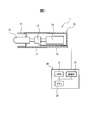
- FIG. 1 is a diagram schematically showing a skin characteristic detection system according to one embodiment.
- FIG. 2 is a diagram schematically showing a skin characteristic detection system when detecting a reaction force by a sensor.
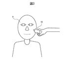
- FIG. 3 is a diagram schematically showing a detection mode when the reaction force is detected by the sensor.
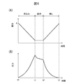
- FIG. 4 is a diagram showing the time transition of the displacement of the contactor and the reaction force of the skin when the contactor of the sensor is moved.
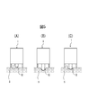
- FIG. 5 is a diagram showing the state of the sensor and the skin at each stage when measuring the reaction force of the skin.
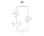
- FIG. 6 is a diagram showing a three-element solid model.
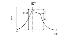
- FIG. 7 is a diagram similar to FIG. 4 (B) showing the time transition of the displacement of the contact when the contact of the sensor is moved.
- FIG. 8 is a diagram similar to FIG. 4 (B) showing the time transition of the displacement of the contact when the contact of the sensor is moved.
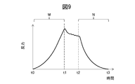
- FIG. 9 is a diagram similar to FIG. 4 (B) showing the time transition of the displacement of the contact when the contact of the sensor is moved.
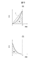
- FIG. 10 is a diagram showing the relationship between the movement distance of the contactor and the reaction force during the period in which the contactor is being moved.
- FIG. 11 is a diagram showing the average value of the parameter k2 for each age group of the subjects.
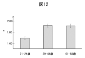
- FIG. 12 is a diagram showing the average value of the parameter a for each age of the subject.
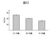
- FIG. 13 is a diagram showing the average value of the parameter RC for each age group of the subjects.
- FIG. 14 is a diagram showing the average value of the parameter k1 for each age group of the subjects.
- FIG. 1 is a diagram schematically showing a skin characteristic detection system 1 according to one embodiment.
- the skin characteristic detection system 1 detects characteristics such as human skin and a human skin model created by imitating human skin, particularly characteristic values expressing a feeling of softness (hereinafter, the characteristic values of human skin are used.
- the case of detection will be described as an example).
- the feeling of softness is the feeling of the skin when touching the skin (skin), especially the softness of the skin (the force of pushing back when the skin is pushed in, the degree of feeling that the skin is clogged when the skin is pushed in). , Tension, softness, etc.).
- the skin characteristic detection system 1 includes a sensor 10 and a processing device 20 electrically connected to the sensor 10.
- the sensor 10 is used to detect the magnitude of the reaction force when the human skin is pushed.
- the processing device 20 is used to detect a characteristic value representing a characteristic of the skin (particularly, a feeling of softness) based on the measurement result of the sensor 10.
- the sensor 10 includes a housing 11, a contact 12, a load cell 13, an actuator 14, a substrate 15, and a cover 16.
- the housing 11 is formed in a cylindrical shape with a resin such as polystyrene.
- the housing 11 houses the load cell 13, the actuator 14, and the substrate 15. Further, the housing 11 has an opening, and the contactor 12 is arranged so as to pass through the opening.
- the contactor 12 is arranged so as to be slidable with respect to the housing 11 in the axial direction thereof. Therefore, the tip of the contact 12 can move outward from the housing 11 and toward the inside of the housing 11.
- the housing 11 may have any outer shape as long as it can accommodate the load cell 13 and the like.
- the contactor 12 is basically formed in a cylindrical shape, and the tip portion is formed in a hemispherical shape.
- the diameter of the contact 12 is 2 to 20 mm, 5 to 15 mm, or 7 to 12 mm.
- the contactor 12 is preferably about 10 mm in size so as to be about the size of a human fingertip.
- the axial length of the contact 12 is, for example, 25 mm.
- the contact 12 is formed of a resin such as polystyrene.
- the tip of the contactor 12 projects out of the housing 11.
- the load cell 13 is an example of a reaction force measuring device that measures the reaction force applied to the contactor 12 from the skin.
- the load cell 13 is, for example, a strain gauge, and measures the reaction force applied from the skin to the contact 12 when the contact 12 is pressed against the skin.
- the load cell 13 is housed in the housing 11 and is connected to and located between the contacts 12 and the actuator 14.
- the actuator 14 constitutes a part of the push amount control device that controls the push amount of the contact 12 into the skin.
- the actuator 14 is composed of a motor or the like, and drives the contactor 12 at an arbitrary speed in the axial direction thereof.
- the board 15 is electrically connected to the load cell 13 and the actuator 14. Further, a part of the wiring of the substrate 15 extends to the outside of the housing 11, and this wiring is connected to the processing device 20 described later. Therefore, the output signal from the load cell 13 is transmitted to the processing device 20 via the substrate 15. Further, the drive signal of the actuator 14 from the processing device 20 is transmitted to the actuator 14 via the substrate 15.
- the cylindrical cover 16 is fixed to the housing 11 so as to surround the contactor 12.
- the cover 16 is formed so that its axial length is shorter than the axial length of the contactor 12. Therefore, the contact 12 can extend beyond the tip of the cover 16.
- the cover 16 is mainly used to protect the contact 12 of the sensor 10 from an external force in the lateral direction during setting of the sensor 10 or during transportation.
- the sensor 10 may include a battery that supplies electric power for driving the actuator 14. Further, the housing 11 may be provided with an illumination such as an LED light around the contactor 12. This makes it easier to visually confirm the contact between the contactor 12 and the skin.
- the processing device 20 is an example of a detection device that detects a characteristic value representing the characteristics of the skin based on the measured reaction force. Further, the processing device 20 constitutes a part of the pushing amount control device that controls the pushing amount of the contact 12 into the skin. It includes a processor such as a CPU 21, a communication interface 22, and a memory 23. The CPU 21, the communication interface 22, and the memory 23 are connected to each other by a bidirectional bus.
- the CPU 21 performs various arithmetic processes.
- the CPU 21 outputs, for example, a control signal of the actuator 14. Based on the transition of the reaction force measured by the load cell 13, the values of various parameters relating to the characteristic values representing the characteristics of the skin are calculated. Further, the CPU 21 transmits a drive signal for driving the actuator 14 via the communication interface 22. Therefore, the CPU 21 controls the amount of pushing the contactor 12 into the skin.
- the communication interface 22 has an interface circuit for connecting the processing device 20 to the sensor 10. Therefore, the communication interface 22 is connected to the sensor 10, receives the output signal from the load cell 13, and transmits the drive signal to the actuator 14.
- the memory 23 includes, for example, a volatile semiconductor memory and a non-volatile semiconductor memory.
- the memory 23 stores the output signal received from the load cell 13.
- the memory 23 stores a computer program for executing various processes by the CPU 21.
- the processing device 20 may be provided with an input device such as a keyboard or a mouse in order to improve the operability of the user who operates the processing device 20. Further, the processing device 20 may include a display for displaying the processing result.
- the senor 10 and the processing device 20 are provided as separate bodies in the present embodiment, the sensor 10 and the processing device 20 may be integrally formed. In this case, for example, the processing device 20 is incorporated in the sensor 10.
- FIG. 2 is a diagram schematically showing the skin characteristic detection system 1 when the reaction force is measured by the sensor 10.
- the skin characteristic detection system 1 includes a sensor fixture 30 and a target fixture 40.
- the sensor fixture 30 is used to fix the sensor 10
- the target fixture 40 is the skin whose reaction force is to be measured (that is, the skin whose characteristic value is to be detected. In the illustrated example, the cheek of the subject. Used to fix the skin).
- the sensor fixture 30 includes a first shaft 31 arranged so as to extend vertically, a second shaft 32 fixed to the first shaft 31, and a first shaft 31 and a second shaft.
- the adjuster 33 for adjusting the relative position with respect to 32 is provided. Therefore, the tip of the second shaft 32 can be arranged at any three-dimensional position.
- a sensor 10 is attached to the tip of the second shaft 32.
- the target fixture 40 fixes the target skin so that it does not move during measurement.
- the head of the subject H is supported so as not to move.
- the target fixture 40 includes a shaft 41 arranged so as to extend vertically, and a fixing plate 42 fixed to the shaft 41.
- the fixing plate 42 is configured so that the subject's head rides at a predetermined angle, and fixes the subject's head so as not to move.
- the sensor 10 moves with respect to the skin to be measured while the actuator 14 is driving the contactor 12 in the direction of pushing it into the skin to be measured or away from the skin, the movement is accompanied by this movement.
- the reaction force measured by the load cell 13 changes. Therefore, it becomes impossible to accurately measure the transition of the reaction force. Therefore, when driving the contactor 12, the sensor 10 and the skin to be measured need not move with each other and the distance must be constant.
- the skin to be measured and the sensor 10 are fixed by the target fixture 40 and the sensor fixture 30, respectively, it is possible to prevent the reaction force measured by the load cell 13 from being changed by an external factor. To.
- FIG. 2 shows an example of a mode in which the reaction force is measured using the sensor 10. Therefore, any fixture may be used as long as the skin to be measured and the sensor 10 do not move with each other and the distance between them is kept constant. Further, the target fixture 40 may also be fixed to the sensor fixture 30. As a result, the sensor 10 fixed by the sensor fixing tool 30 is fixed to the head of the subject (that is, the skin of the target) fixed by the target fixing tool 40. Therefore, the distance between the sensor 10 and the skin to be measured can be more reliably maintained constant.
- the sensor 10 since the force applied to the skin from the sensor 10 is not so large, it is unlikely that the cheeks and the like will be pushed by the sensor 10 during the measurement, and therefore the skin to be measured is not necessarily fixed by the fixture. May be good. Therefore, for example, as shown in FIG. 3, the sensor 10 may be held by the hand of the measurement target person or an assistant who assists the measurement without using the sensor fixture 30.
- the senor 10 may be configured so that a part of the sensor 10 other than the contactor 12 comes into contact with the skin when the measurement is performed by the sensor 10. This suppresses changes in the distance between the skin and the sensor during measurement.
- the sensor 10 is configured so that the tip of the cover 16 comes into contact with the skin when performing a measurement.
- the cover 16 functions as a fixing member for fixing the relative position of the sensor 10 with respect to the skin.
- FIG. 4 is a diagram showing the time transition of the displacement of the contactor 12 (the amount of the contactor 12 pushed into the skin) and the reaction force of the skin S when the contactor 12 of the sensor 10 is moved.
- FIG. 5 is a diagram showing the state of the sensor 10 and the skin S at each stage when measuring the reaction force of the skin S.
- the sensor 10 is installed so that the tip of the contactor 12 is close to the skin S to be measured while the contactor 12 is contracted. Specifically, the sensor 10 is installed by adjusting the adjusting tool 33 of the sensor fixing tool 30. At this time, since the contactor 12 does not receive the reaction force from the skin S, the reaction force measured by the load cell 13 is zero as shown at time t0 in FIG. 4 (B).
- the actuator 14 drives the contactor 12 in the direction toward the outside of the sensor 10, that is, in the direction in which the skin S is pushed (the direction indicated by the arrow in FIG. 5A).
- the actuator 14 moves the contactor 12 at a constant speed. Therefore, the amount of pushing the contactor 12 into the skin S increases at a constant rate.
- the reaction force from the skin S to the contact 12 gradually increases as the amount of pushing the contact 12 into the skin S increases, as shown in FIG. 4 (B).
- the movement of the contactor 12 is stopped (time t1). Therefore, the contactor 12 is maintained in a state of being pushed into the skin S as shown in FIG. 5 (B). At this time, the reaction force from the skin S to the contactor 12 gradually decreases due to stress relaxation in the skin S, as shown in FIG. 4 (B).
- the time for maintaining the contact 12 in the stopped state is the time required for the decrease in the reaction force due to stress relaxation to almost converge, for example, 0.5 to 6 seconds, 0.5 to 4 seconds, or 1 ⁇ 2 seconds.
- the actuator 14 drives the contactor 12 in the direction toward the inside of the sensor 10, that is, in the direction away from the skin S (the direction indicated by the arrow in FIG. 5C). Therefore, the push of the contactor 12 into the skin is returned.
- the actuator 14 moves the contactor 12 at a constant speed.
- the moving speed at this time is the same as the speed at the time of pushing before the time t1. Therefore, the amount of the contactor 12 pushed into the skin S decreases at a constant rate.
- the reaction force from the skin S to the contact 12 gradually decreases as the amount of pushing the contact 12 into the skin S decreases, as shown in FIG. 4 (B). Then, at time t3, the amount of pushing the contactor 12 into the skin S becomes zero, and at this time, the reaction force measured by the load cell also returns to zero.
- the processing apparatus 20 detects characteristic values representing various characteristics of the skin based on the reaction force data measured in this way.
- the actuator 14 increases the amount of the contactor 12 pushed into the skin at a constant speed, then keeps it constant, and then decreases it at a constant speed.
- the actuator 14 may be driven in a different manner.
- the actuator 14 may increase the amount of push of the contactor 12 into the skin at a constant speed and then decrease it at a constant speed without maintaining the amount of push at a constant level.
- ⁇ Parameters related to approximation in a three-element solid model As a parameter representing the characteristics of the skin, the value of each parameter representing this model is detected when the viscoelastic property of the skin is approximated by a three-element solid model (standard linear solid model).
- FIG. 6 A three-element solid model is shown in FIG. As shown in FIG. 6, in the three-element solid model, the second linear spring having the spring constant k2 and the dashpot having the viscosity coefficient C are arranged in series. In addition, these second linear springs and dashpots arranged in series and the first linear spring having a spring constant k1 are arranged in parallel.
- ⁇ m ⁇ exp ( ⁇ nt) + C... (3)
- ⁇ represents a reaction force
- t time
- m and n constants.
- each parameter representing this model that is, each parameter representing the characteristics of the measurement target
- the value can be identified.
- FIG. 7 is a diagram similar to FIG. 4 (B) showing the time transition of the displacement of the contact when the contact 12 of the sensor 10 is moved. It is considered that the reaction force on the contactor 12 is not easily affected by the viscosity and is therefore mainly affected by the two linear springs from the start of pushing the contactor 12 into the skin until the pushing is stopped. Be done. Therefore, in the present embodiment, the relationship between the reaction force (that is, the maximum value of the reaction force; “k1 + k2” in FIG. 7) at the time t1 when the pushing into the skin into the contactor 12 is stopped and the displacement amount of the contactor 12. From, the value (k1 + k2) obtained by adding the spring constants k1 and k2 of the two linear springs is approximately calculated.
- the value (k1 + k2) obtained by adding the spring constants k1 and k2 of the two linear springs is approximated to the elastic change of the reaction force when the amount of the contactor 12 pushed into the skin is increased at a constant speed. It represents the elastic modulus.
- the first linear spring is based on the relationship between the reaction force (“k1” in FIG. 7) at time t2 immediately before the contact 12 is pushed back into the skin and the amount of the contact 12 pushed into the skin.
- the spring constant k1 of is approximately calculated.
- the spring constant k1 of the first linear spring represents an elastic modulus when the reaction force is approximated to change elastically when the amount of pushing of the contactor 12 into the skin is reduced at a constant speed.
- the spring constant k2 of the second linear spring is calculated by subtracting the spring constant k1 of the first linear spring from the total value (k1 + k2) of the spring constants obtained as described above. That is, in the present embodiment, when the viscoelastic property of the skin is approximated by the three-element solid model in this way, the spring constant k2 of the linear spring connected in series with the dashpot is calculated.
- the spring constant k2 of this linear spring is an example of the value of the parameter representing the change in the reaction force when the pushing amount by the contactor 12 is kept constant.
- the constants m and n are identified from the reaction force data between the time t1 and the time t2 by a general approximation method such as the least squares method.
- the spring constant k2 the total value k1 + k2 of both spring constants, the time constant ⁇ in stress relaxation, and the viscoelasticity coefficient C are calculated.
- ⁇ Parameters related to the transition of reaction force during pushing ⁇ As a parameter representing the characteristics of the skin, the transition of the reaction force while increasing the amount of the contactor 12 pushed into the skin at a constant speed (in the region surrounded by the broken line in FIG. 8). Parameters related to transition) are used.
- ⁇ k0 ⁇ d a ... ( 4)
- k0 is a parameter related to the rigidity of the skin
- d is the amount of the contactor 12 pushed into the skin.
- a represents the degree to which the waveform of the reaction force while pushing the skin by the contactor 12 is curved. If the skin is not viscous, the waveform of the reaction force during pushing becomes linear, so it is considered that a is a parameter that changes according to the viscosity of the skin.
- a is an example of a parameter representing the non-linearity of the reaction force with respect to the pushing amount when the pushing amount of the contact 12 into the skin is increased at a constant speed.
- the parameter a represents the non-linearity of the reaction force
- k0 is the skin in consideration of the non-linearity of the reaction force when the amount of pushing the contactor 12 into the skin is increased at a constant speed. It can be said that it is a parameter representing rigidity.
- the constants k0 and a are identified from the reaction force data between the time t0 and the time t1 by a general approximation method such as the least squares method.
- a parameter representing the characteristics of the skin a parameter relating to the integrated value of the reaction force while the contactor 12 is being pushed into the skin and while the contactor 12 is being pushed back is used.
- FIG. 9 is a diagram similar to FIG. 4 (B) showing the time transition of the displacement of the contact 12 when the contact 12 of the sensor 10 is moved.
- FIG. 10 is a diagram showing the relationship between the movement distance of the contactor 12 and the reaction force during the period in which the contactor 12 is being moved.
- FIG. 10A shows the relationship between the moving distance of the contactor 12 and the reaction force when the contactor 12 is pushed into the skin (period M in FIG. 9)
- FIG. 10B shows the relationship. It is a figure which shows the relationship between the movement distance of the contactor 12 and the reaction force at the time of returning the pushing of the contactor 12 into the skin (period N of FIG. 9).
- WC in FIG. 10A is an integrated value obtained by integrating the reaction force while pushing the contactor 12 into the skin with the moving distance of the contactor 12.
- WC represents the energy stored in the skin while pushing the contactor 12 into the skin.
- the reaction force measured from the start of pushing when the moving distance is 0 to the completion of pushing when the moving distance is d1 is used.
- the WC is calculated by integrating.
- RWC in FIG. 10B is an integrated value obtained by integrating the reaction force while the contactor 12 is being pushed back into the skin by the moving distance of the contactor 12.
- the RWC represents the energy released from the skin when the contactor 12 is being pushed back into the skin.
- the RWC starts pushing back in the state where the moving distance is 0 until the pushing back is completed in the state where the moving distance is d1. It is calculated by integrating the reaction force measured in.
- RC is calculated by dividing the RWC calculated as described above by WC.
- the energy stored in the skin while pushing the contactor 12 into the skin is It is represented as the area X of the triangle shown by the broken line in FIG.
- the value of LC becomes 1 if the waveform of the reaction force while pushing the skin by the contactor 12 is linear, and becomes a value away from 1 as the degree of curvature of the waveform of the reaction force during this period increases.
- LC is calculated based on the reaction force until the contactor 12 stops pushing into the skin.
- LC may be calculated based on the reaction force from the start of pushing the skin into the contact 12 to any time point before stopping the pushing of the contact 12 into the skin.
- the integrated value of the reaction force from the start of the increase in the pushing amount to the time when the pushing amount reaches the predetermined amount when the pushing amount and the reaction force are assumed to increase at a constant speed. It can be said that it is the ratio of.
- the actuator 14 increases the amount of push of the contactor 12 into the skin at a constant speed, then keeps it constant, and then decreases it at a constant speed. In this case, it is possible to calculate the values of all the above-mentioned parameters as the characteristic values related to the characteristics of the skin.
- the actuator 14 when the actuator 14 is driven in a different mode, it is not always possible to calculate the values of all the parameters.
- the actuator 14 may increase the amount of push of the contactor 12 into the skin at a constant speed and then decrease at a constant speed without maintaining the amount of push.
- the parameter values that can be calculated by keeping the amount of the contactor 12 pushed into the skin constant for example, the values of k2, ⁇ , and C are not calculated.
- the values of other parameters that are calculated regardless of maintaining the amount of the contactor 12 pushed into the skin constant can be calculated.
- the parameters k2, k0, a, WC, RC, and LC have a high correlation with the sensory evaluation results regarding the feeling of flexibility by a skilled evaluator.
- the parameters k1 + k2 and C also have a relatively high correlation with the sensory evaluation results regarding the feeling of flexibility by a skilled evaluator. Therefore, these parameters can be used as a new index indicating the softness of the skin. That is, according to the skin characteristic detection system 1 described above, it can be said that it is possible to detect the value of a parameter that is a new index indicating the softness of the skin.
- FIG. 11 is a diagram showing the average value of the parameter k2 for each age group of the subjects.
- the I-shaped display in the figure indicates a standard error (hereinafter, the same applies to FIGS. 12 to 14).
- the value of the parameter k2 is small at 21 to 24 years old (that is, the change in reaction force when the pushing amount by the contactor 12 is kept constant is small), whereas it is 39 to 44 years old.
- the value of k2 increases as the age increases from 61 to 68 years old. Therefore, it can be said that the parameter k2 represents the difference in the softness of the skin depending on the age.
- FIG. 12 is a diagram showing the average value of the parameter a for each age group of the subjects.
- the value of the parameter a is small at the age of 21 to 24 (that is, the degree of curvature of the reaction force waveform while pushing the skin by the contactor 12 is small).
- the value of a is large in 39-44 years old and 61-68 years old. Therefore, it can be said that the parameter a represents the difference in the softness of the skin depending on the age.
- FIG. 13 is a diagram showing the average value of the parameter RC for each age group of the subjects.
- the RC value is large at 21 to 24 years old (that is, the proportion of energy not released by stress relaxation is small), whereas the age groups are 39 to 44 years old and 61 to 68 years old.
- the value of RC decreases as it increases. Therefore, it can be said that the parameter RC also represents the difference in the softness of the skin depending on the age.
- FIG. 14 is a diagram showing the average value of the parameter k1 for each age group of the subjects. As can be seen from FIG. 14, the value of k1 does not show a constant tendency according to age. Therefore, it cannot be said that the parameter k1 does not necessarily represent the difference in the softness of the skin depending on the age.
- the parameters other than the parameters k2, k0, a, WC, RC and LC have a high correlation with the softness of the skin.
- these parameters can also be used as parameters representing the characteristics of the skin.
- the values of a large number of parameters related to the skin properties can be detected by one simple test, and thus the skin can be easily evaluated.
Landscapes
- Life Sciences & Earth Sciences (AREA)
- Health & Medical Sciences (AREA)
- Medical Informatics (AREA)
- Biophysics (AREA)
- Pathology (AREA)
- Engineering & Computer Science (AREA)
- Biomedical Technology (AREA)
- Heart & Thoracic Surgery (AREA)
- Physics & Mathematics (AREA)
- Molecular Biology (AREA)
- Surgery (AREA)
- Animal Behavior & Ethology (AREA)
- General Health & Medical Sciences (AREA)
- Public Health (AREA)
- Veterinary Medicine (AREA)
- Measuring And Recording Apparatus For Diagnosis (AREA)
- Measurement Of The Respiration, Hearing Ability, Form, And Blood Characteristics Of Living Organisms (AREA)
Abstract
皮膚の特性を表す特性値を検出する皮膚特性検出システム1は、接触子12の皮膚への押し込み量を制御する押し込み量制御装置14と、皮膚から接触子に加わる反力を測定する反力測定装置13と、測定された反力に基づいて前記特性値を検出する検出装置20と、を備える。押し込み量制御装置は、接触子の皮膚への押し込み量を一定の速度で増大させること及び接触子によって皮膚を押し込んだ後に押し込み量を一定に維持することのうち少なくともいずれか一方を実行する。特性値は、接触子の皮膚への押し込み量を一定の速度で増大させたときの押し込み量に対する反力の非線形性を表すパラメータ、及び押し込み量を一定に維持したときの反力の変化を表すパラメータ等を含む。
Description
本開示は、皮膚特性検出システム及び皮膚特性検出方法に関する。
皮膚(肌)を触ったときに感じる柔軟感(例えば、皮膚を押し込んだときに皮膚に押し返されたと感じる力の大きさ、皮膚を押し込んだときに皮膚が詰まっていると感じる度合い、等)を定量的に捉えるべく、様々なシステムが提案されている。斯かるシステムとして、例えば、プローブにより皮膚に陰圧を加えて皮膚表面を一定期間吸引し、その後、陰圧を除去し、その過程での皮膚表面における変位を測定するシステムが知られている。このシステムでは、陰圧を印加、除去する過程での皮膚表面における変化に関するパラメータを、皮膚の柔軟感を示す指標として検出している。
他には、斯かるシステムとして、接触子で皮膚を押し込んだときに接触子に加わる圧力をロードセルにより測定するシステムが提案されている(例えば、特許文献1)。このシステムでは、接触子に加わる圧力の最大値を、皮膚の柔軟感を示す指標として検出している。
一方で、柔軟感を知覚する際に機能する機械受容器は未だに特定されていない。このため、機械受容器を特定すべく、物理的な外的刺激と内的な感覚との対応関係を測定する様々な心理物理実験が行われている。この結果、例えば、対象物に触れたときの剛性の弁別閾(丁度可知差異)には機械的仕事(変位に対して積分された力)及び最終的な抵抗力が関係していることが報告されている(例えば、非特許文献1)。また、対象物を押し込む際の反力の増加率が剛性知覚の代替になり得ることが報告されている(例えば、非特許文献2)。
Hong Z. Tan、他3名、「Manual discrimination of compliance using active pinch grasp: The roles of force and work cues」、Perception & Psychophysics、Psychonomic Society、1995年6月、Volume 57、Issue 4、p.495-510
Dale A. Lawrence、他3名、「Rate-hardness: a New performance metric for haptic interfaces」、IEEE Transactions on Robotics and Automation、IEEE、2000年8月、Volume 16、Issue 4、p.357-371
しかしながら、特許文献1で用いられている指標では、皮膚を触ったときに感じる実際の柔軟感を必ずしも精度良く評価することができていなかった。換言すると、上述したような指標は、実際の柔軟感との間に必ずしも十分な相関を得られていなかった。これは、非特許文献1や非特許文献2による報告を考慮すれば、柔軟感は、圧力の最大値といった単純なパラメータのみで決定できるものではないことによるものだと考えられる。このため、皮膚の柔軟感を表す新たな指標が必要とされている。
上記課題に鑑みて、本開示の目的は、皮膚の柔軟感を表す新たな指標となるパラメータの値を検出することができる皮膚特性検出システムを提供することにある。
本開示の要旨は以下のとおりである。
[1]皮膚の特性を表す特性値を検出する皮膚特性検出システムであって、接触子の皮膚への押し込み量を制御する押し込み量制御装置と、皮膚から接触子に加わる反力を測定する反力測定装置と、前記測定された反力に基づいて前記特性値を検出する検出装置と、を備え、前記押し込み量制御装置は、前記接触子の皮膚への押し込み量を一定の速度で増大させること、前記接触子によって皮膚を押し込んだ後に押し込み量を一定に維持すること及び前記接触子の皮膚への押し込み量を一定の速度で減少させることのうち少なくともいずれか一つを実行し、前記特性値は、前記接触子の皮膚への押し込み量を一定の速度で増大させたときの前記押し込み量に対する前記反力の非線形性を表すパラメータ、前記接触子の皮膚への押し込み量を一定の速度で増大させたときの前記反力の非線形性を考慮した皮膚の剛性を表すパラメータ、前記押し込み量を一定に維持したときの前記反力の変化を表すパラメータ、及び前記押し込み量を一定に維持したときに開放されなかったエネルギの割合を表すパラメータのうちの少なくともいずれか一つの値を含む、皮膚特性検出システム。
[2]前記接触子の皮膚への押し込み量を一定の速度で増大させたときの前記押し込み量に対する前記反力の非線形性を表すパラメータの値は、前記接触子の皮膚への押し込み量を一定の速度で増大させたときの前記反力の推移を下記式(1)によって近似したときのaであり、
σ=k0・da …(1)
前記式(1)においてσは反力、dは押し込み量、k0は定数である、上記[1]に記載の皮膚特性検出システム。
[3]前記接触子の皮膚への押し込み量を一定の速度で増大させたときの前記押し込み量に対する前記反力の非線形性を表すパラメータの値は、前記押し込み量の増大を開始してから前記押し込み量が所定量に到達するまでの間に測定された反力の積分値と、前記押し込み量の増大を開始してから前記押し込み量が所定量に到達したときの反力まで前記押し込み量及び反力が一定速度で増大したと仮定したときに前記押し込み量の増大を開始してから前記押し込み量が所定量に到達するまでの間の反力の積分値との比率である、上記[1]又は[2]に記載の皮膚特性検出システム。
[4]前記接触子の皮膚への押し込み量を一定の速度で増大させたときの前記反力の非線形性を考慮した皮膚の剛性を表すパラメータの値は、前記接触子の皮膚への押し込み量を一定の速度で増大させたときの前記反力の推移を下記式(2)によって近似したときのk0であり、
σ=k0・da …(2)
前記式(2)においてσは反力、dは押し込み量、aは定数である、上記[1]~[3]のいずれか1つに記載の皮膚特性検出システム。
[5]前記押し込み量を一定に維持したときの前記反力の変化を表すパラメータの値は、前記皮膚の粘弾性特性を3要素固体モデルで近似したときに、ダッシュポットと直列に連結された線形バネのバネ定数に相当する、上記[1]~[4]のいずれか1つに記載の皮膚特性検出システム。
[6]前記押し込み量を一定に維持したときの前記反力の変化を表すパラメータの値は、前記接触子の皮膚への押し込み量を一定速度で増大させたときに反力が弾性的に変化したと近似したときの弾性係数から、前記接触子の皮膚への押し込み量を一定速度で減少させたときに反力が弾性的に変化したと近似したときの弾性係数を減算した値である、上記[1]~[5]のいずれか1つに記載の皮膚特性検出システム。
[7]前記押し込み量を一定に維持したときに開放されなかったエネルギの割合を表すパラメータの値は、前記押し込み量の増大を開始してから前記押し込み量が所定量に到達するまでの間に測定された反力の積分値と、前記押し込み量を前記所定量から前記押し込み量の増大を開始したときの押し込み量まで減少させている間に測定された反力の積分値との比率である、上記[1]~[6]のいずれか1つに記載の皮膚特性検出システム。
[8]前記特性値は、前記押し込み量の増大を開始してから所定時間が経過するまでの間に測定された反力の積分値を含む、上記[1]~[7]のいずれか1つに記載の皮膚特性検出システム。
[9]前記押し込み量制御装置は、前記接触子の皮膚への押し込み量を一定の速度で増大させ、次いで一定に維持し、その後、一定の速度で減少させるように構成される、上記[1]~[8]のいずれか1つに記載の皮膚特性検出システム。
[10]前記押し込み量制御装置は、前記接触子の皮膚への押し込み量を一定の速度で増大させ、その後、前記押し込み量を一定に維持することなく、一定の速度で減少させるように構成される、上記[1]~[8]のいずれか1つに記載の皮膚特性検出システム。
[11]皮膚の特性を表す特性値を検出する皮膚特性検出方法であって、接触子の皮膚への押し込み量を一定の速度で増大させたとき、前記接触子によって皮膚を押し込んだ後に押し込み量を一定に維持したとき、及び前記接触子の皮膚への押し込み量を一定の速度で減少させたときのうちの少なくともいずれか一つのときに皮膚から前記接触子に加わる反力を測定することと、前記測定された反力に基づいて前記特性値を検出することと、を含み、前記特性値は、前記接触子の皮膚への押し込み量を一定の速度で増大させたときの前記押し込み量に対する前記反力の非線形性を表すパラメータ、前記接触子の皮膚への押し込み量を一定の速度で増大させたときの前記反力の非線形性を考慮した皮膚の剛性を表すパラメータ、前記押し込み量を一定に維持したときの前記反力の変化を表すパラメータ及び前記押し込み量を一定に維持したときに開放されなかったエネルギの割合を表すパラメータのうちの少なくともいずれか一つの値を含む、皮膚特性検出方法。
本開示によれば、皮膚の柔軟感を表す新たな指標となるパラメータの値を検出することができる皮膚特性検出システムが提供される。
以下、図面を参照して実施形態について詳細に説明する。なお、以下の説明では、同様な構成要素には同一の参照番号を付す。
<皮膚特性検出システムの構成>
図1は、一つの実施形態に係る皮膚特性検出システム1を概略的に示す図である。皮膚特性検出システム1は、人の皮膚や、人の皮膚に模して作成された人肌モデル等の特性、特に柔軟感を表す特性値を検出する(以下では、人の皮膚の特性値を検出する場合を例にとって説明する)。ここで、柔軟感は、皮膚(肌)を触ったときに感じる肌の感触、特に皮膚の柔軟性(皮膚を押し込んだときに押し返す力、皮膚を押し込んだときに皮膚が詰まっていると感じる度合い、ハリ、柔らかさ、等)に関する特性を意味する。
図1は、一つの実施形態に係る皮膚特性検出システム1を概略的に示す図である。皮膚特性検出システム1は、人の皮膚や、人の皮膚に模して作成された人肌モデル等の特性、特に柔軟感を表す特性値を検出する(以下では、人の皮膚の特性値を検出する場合を例にとって説明する)。ここで、柔軟感は、皮膚(肌)を触ったときに感じる肌の感触、特に皮膚の柔軟性(皮膚を押し込んだときに押し返す力、皮膚を押し込んだときに皮膚が詰まっていると感じる度合い、ハリ、柔らかさ、等)に関する特性を意味する。
図1に示したように、皮膚特性検出システム1は、センサ10と、センサ10に電気的に接続された処理装置20とを備える。センサ10は、人の皮膚を押し込んだときの反力の大きさを検出するのに用いられる。処理装置20は、センサ10の測定結果に基づいて、皮膚の特性(特に、柔軟感)を表す特性値を検出するのに用いられる。
センサ10は、ハウジング11、接触子12、ロードセル13、アクチュエータ14、基板15及びカバー16を備える。
本実施形態では、ハウジング11は、ポリスチレン等の樹脂により、円筒状に形成される。ハウジング11は、ロードセル13、アクチュエータ14及び基板15を収容する。また、ハウジング11は開口部を有し、この開口部を通るように接触子12が配置される。接触子12は、その軸線方向において、ハウジング11に対して摺動することができるように配置される。したがって、接触子12はその先端部がハウジング11から外部へ向かって及びハウジング11内に向かって移動することができる。なお、ロードセル13等を収容することができれば、ハウジング11は如何なる外形を有していてもよい。
接触子12は、基本的に円筒状に形成されると共に、先端部が半球状に形成される。特に、本実施形態では、接触子12の直径は2~20mm、5~15mm、又は7~12mmである。特に、接触子12は、人の指先程度の大きさとなるように、10mm程度であるのが好ましい。また、接触子12の軸線方向の長さは、例えば、25mmである。接触子12は、ポリスチレン等の樹脂により形成される。接触子12の先端部は、ハウジング11の外へ突出している。
ロードセル13は、皮膚から接触子12に加わる反力を測定する反力測定装置の一例である。ロードセル13は、例えば、歪みゲージであり、接触子12が皮膚に押圧されたときに皮膚から接触子12に加わる反力を測定する。ロードセル13は、ハウジング11内に収容され、また、接触子12及びアクチュエータ14に連結されてこれらの間に位置する。
アクチュエータ14は、接触子12の皮膚への押し込み量を制御する押し込み量制御装置の一部を構成する。アクチュエータ14は、モータ等によって構成され、接触子12を任意の速度でその軸線方向に駆動する。
基板15は、ロードセル13及びアクチュエータ14に電気的に接続される。また、基板15の配線の一部はハウジング11の外部に延びており、この配線は後述する処理装置20に接続される。したがって、ロードセル13からの出力信号は基板15を介して処理装置20に送信される。また、処理装置20からのアクチュエータ14の駆動信号は基板15を介してアクチュエータ14に送信される。
円筒状のカバー16は、接触子12を囲うようにハウジング11に固定される。カバー16は、その軸線方向の長さが接触子12の軸線方向の長さよりも短くなるように形成される。したがって、接触子12は、カバー16の先端を超えて伸びることができる。カバー16は、主にセンサ10のセッティングや運送中等にセンサ10の接触子12を横方向の外力から守るのに用いられる。
なお、センサ10は、アクチュエータ14を駆動するための電力を供給するバッテリを備えてもよい。また、ハウジング11には接触子12の周りにおいてLEDライト等の照明が設けられてもよい。これにより、接触子12と皮膚との接触を目視によって確認しやすくなる。
処理装置20は、測定された反力に基づいて皮膚の特性を表す特性値を検出する検出装置の一例である。また、処理装置20は、接触子12の皮膚への押し込み量を制御する押し込み量制御装置の一部を構成する。CPU21等のプロセッサ、通信インターフェース22及びメモリ23を備える。これらCPU21、通信インターフェース22及びメモリ23は双方向バスによって互いに接続されている。
CPU21は、各種の演算処理を行う。CPU21は、例えば、アクチュエータ14の制御信号を出力する。ロードセル13によって測定された反力の推移に基づいて、皮膚の特性を表す特性値に関する各種パラメータの値を算出する。また、CPU21は、通信インターフェース22を介して、アクチュエータ14を駆動する駆動信号を送信する。したがって、CPU21は、接触子12の皮膚への押し込み量を制御する。
通信インターフェース22は、処理装置20をセンサ10に接続するためのインターフェース回路を有する。したがって、通信インターフェース22は、センサ10に接続されて、ロードセル13からの出力信号を受信し、アクチュエータ14へ駆動信号を送信する。
メモリ23は、例えば、揮発性の半導体メモリ及び不揮発性の半導体メモリを有する。メモリ23は、ロードセル13から受信した出力信号を記憶する。加えて、メモリ23は、CPU21によって各種処理を実行するためのコンピュータプログラムを記憶する。
処理装置20は、処理装置20を操作するユーザの操作性を高めるために、キーボードやマウス等の入力装置を備えてもよい。また、処理装置20は、処理結果を表示するためのディスプレイを備えてもよい。
なお、本実施形態では、センサ10と処理装置20とは別体として設けられているが、センサ10と処理装置20とは一体的に形成されてもよい。この場合、例えば、処理装置20がセンサ10に組み込まれる。
図2は、センサ10によって反力を測定するときの皮膚特性検出システム1を概略的に示す図である。図2に示したように、皮膚特性検出システム1は、センサ固定具30及び対象固定具40を備える。センサ固定具30は、センサ10を固定するのに用いられ、対象固定具40は、反力の測定対象の皮膚(すなわち、特性値の検出対象となる皮膚。図示した例では、対象者の頬の皮膚)を固定するのに用いられる。
図2に示したように、センサ固定具30は、鉛直に延びるように配置される第1シャフト31と、第1シャフト31に固定される第2シャフト32と、第1シャフト31と第2シャフト32との相対位置を調整する調整具33とを備える。したがって、第2シャフト32の先端は任意の3次元的な位置に配置されることができる。また、第2シャフト32の先端にはセンサ10が取り付けられる。
対象固定具40は、測定中に対象の皮膚が動かないように固定する。図2に示した例では、対象者の頭Hが動かないように頭を支えている。本実施形態では、対象固定具40は、鉛直に伸びるように配置されるシャフト41と、シャフト41に固定される固定プレート42とを備える。固定プレート42は、対象者の頭が所定の角度で乗るように構成され、対象者の頭を動かないように固定する。
ここで、アクチュエータ14により接触子12を測定対象の皮膚に押し込む方向又は皮膚から離れる方向に駆動しているときに、センサ10が測定対象の皮膚に対して動いてしまうと、この動きに伴ってロードセル13によって測定される反力が変化してしまう。このため、正確な反力の推移を測定することができなくなる。したがって、接触子12を駆動しているときには、センサ10と測定対象の皮膚とは互いに動かず、距離が一定である必要がある。本実施形態では、測定対象の皮膚及びセンサ10がそれぞれ対象固定具40及びセンサ固定具30によって固定されるため、ロードセル13によって測定される反力が外的要因によって変化してしまうことが抑制される。
なお、図2は、センサ10を用いて反力を測定する態様の一例を示している。したがって、測定対象の皮膚とセンサ10とが互いに動かずにその間の距離が一定に保たれれば、どのような固定具が用いられてもよい。また、対象固定具40は、センサ固定具30に対しても固定されてもよい。これによって、対象固定具40によって固定された対象者の頭(すなわち、対象の皮膚)に対して、センサ固定具30によって固定されたセンサ10が固定される。このため、センサ10と測定対象の皮膚との距離をより確実に一定に維持することができる。
また、センサ10から皮膚に加わる力はそれほど大きくないため、測定中にセンサ10に押されて頬等が動いてしまう可能性は低く、よって測定対象の皮膚は必ずしも固定具によって固定されていなくてもよい。したがって、例えば、図3に示したように、センサ固定具30を用いずに、測定対象者又は測定を補助する補助者の手によってセンサ10を保持するようにしてもよい。
この場合、センサ10は、センサ10によって測定を行うときには、接触子12以外のセンサ10の一部が皮膚に接触するように構成されてもよい。これにより、測定中に皮膚とセンサとの距離が変化することが抑制される。具体的には、例えば、センサ10は、測定を行うときに、カバー16の先端が皮膚に接触されるように構成される。この場合、カバー16は、皮膚に対するセンサ10の相対位置を固定する固定部材として機能する。
<センサの動作>
次に、図4及び図5を参照して、センサ10によって皮膚Sの反力を測定するときのセンサ10の動作について説明する。図4は、センサ10の接触子12を移動させたときの接触子12の変位(接触子12の皮膚への押し込み量)及び皮膚Sの反力の時間推移を示す図である。図5は、皮膚Sの反力を測定するときの各段階におけるセンサ10及び皮膚Sの様子を示す図である。
次に、図4及び図5を参照して、センサ10によって皮膚Sの反力を測定するときのセンサ10の動作について説明する。図4は、センサ10の接触子12を移動させたときの接触子12の変位(接触子12の皮膚への押し込み量)及び皮膚Sの反力の時間推移を示す図である。図5は、皮膚Sの反力を測定するときの各段階におけるセンサ10及び皮膚Sの様子を示す図である。
まず、図5(A)に示したように、接触子12が収縮した状態で、接触子12の先端部が測定対象の皮膚Sに近接するように、センサ10が設置される。具体的には、センサ固定具30の調整具33を調整することによってセンサ10の設置が行われる。このとき、接触子12は皮膚Sからの反力を受けていないため、図4(B)に時刻t0で示したように、ロードセル13によって測定される反力はゼロである。
その後、アクチュエータ14により接触子12がセンサ10の外部へ向かう方向、すなわち皮膚Sを押し込む方向(図5(A)に矢印で示した方向)に駆動される。図4(A)に示したように、アクチュエータ14は、接触子12を一定の速度で移動させる。したがって、接触子12の皮膚Sへの押し込み量は一定の速度で増大する。このとき、皮膚Sから接触子12への反力は、図4(B)に示したように、接触子12の皮膚Sへの押し込み量の増大に伴って徐々に増大する。
接触子12の皮膚Sへの押し込み量が予め定められた一定の量(例えば、1~10mm、2~8mm又は2~6mm)になると、接触子12の移動が停止される(時刻t1)。したがって、接触子12は、図5(B)に示したように、皮膚Sへ押し込まれた状態で維持される。このとき、皮膚Sから接触子12への反力は、図4(B)に示したように、皮膚Sにおける応力緩和により、徐々に減少する。接触子12を停止させた状態で維持する時間は、応力緩和による反力の低下がほぼ収束するのにかかる時間であり、例えば、0.5~6秒、0.5~4秒、又は1~2秒である。
その後、アクチュエータ14により接触子12がセンサ10内へ向かう方向、すなわち皮膚Sから離れる方向(図5(C)に矢印で示した方向)に駆動される。したがって、接触子12の皮膚への押し込みが戻される。図4(A)に示したように、アクチュエータ14は、接触子12を一定の速度で移動させる。特に、このときの移動速度は、時刻t1以前の押し込みの際の速度と同一の速度である。したがって、接触子12の皮膚Sへの押し込み量は一定の速度で減少する。このとき、皮膚Sから接触子12への反力は、図4(B)に示したように、接触子12の皮膚Sへの押し込み量の減少に伴って徐々に減少する。そして、時刻t3において、接触子12の皮膚Sへの押し込み量がゼロになり、このときロードセルによって測定される反力もゼロに戻る。
センサ10の接触子12をこのように移動させる間に、ロードセル13によって図4(B)に示したような反力の推移が測定される。測定されたデータは、処理装置20に送信され、処理装置20のメモリ23に記憶される。本実施形態では、このようにして測定された反力のデータに基づいて処理装置20において皮膚の様々な特性を表す特性値が検出される。
なお、本実施形態では、アクチュエータ14は、接触子12の皮膚への押し込み量を一定の速度で増大させ、次いで一定に維持し、その後、一定の速度で減少させている。しかしながら、アクチュエータ14は、これとは異なる態様で駆動されてもよい。例えば、アクチュエータ14は、接触子12の皮膚への押し込み量を一定の速度で増大させ、その後、押し込み量を一定に維持することなく、一定の速度で減少させてもよい。
<皮膚の特性を表すパラメータ>
次に、図6~図8を参照して、このようにして測定された反力のデータに基づいて算出することができる皮膚の様々な特性に関する特性値について説明する。
次に、図6~図8を参照して、このようにして測定された反力のデータに基づいて算出することができる皮膚の様々な特性に関する特性値について説明する。
≪3要素固体モデルでの近似に関するパラメータ≫
本実施形態では、皮膚の特性を表すパラメータとして、皮膚の粘弾性特性を3要素固体モデル(標準線形固体モデル)で近似したときにこのモデルを表す各パラメータの値が検出される。
本実施形態では、皮膚の特性を表すパラメータとして、皮膚の粘弾性特性を3要素固体モデル(標準線形固体モデル)で近似したときにこのモデルを表す各パラメータの値が検出される。
3要素固体モデルを図6に示す。図6に示したように、3要素固体モデルでは、バネ定数k2を有する第2線形バネと粘性係数Cを有するダッシュポットが直列に並ぶ。加えて、これら直列に並んだ第2線形バネ及びダッシュポットと、バネ定数k1を有する第1線形バネが並列に並ぶ。このような3要素固体モデルでは、応力緩和における時間と応力の関係が下記式(3)で表わされる。
σ=m・exp(-nt)+C …(3)
式(3)において、σは反力、tは時間を表しており、m、nは定数である。このように皮膚の粘弾性特性を3要素固体モデルで近似すると、図4(B)に示した反力の推移から、このモデルを表す各パラメータ(すなわち、測定対象の特徴を表す各パラメータ)の値を同定することができる。
σ=m・exp(-nt)+C …(3)
式(3)において、σは反力、tは時間を表しており、m、nは定数である。このように皮膚の粘弾性特性を3要素固体モデルで近似すると、図4(B)に示した反力の推移から、このモデルを表す各パラメータ(すなわち、測定対象の特徴を表す各パラメータ)の値を同定することができる。
図7は、センサ10の接触子12を移動させたときの接触子の変位の時間推移を示す、図4(B)と同様な図である。接触子12の皮膚への押し込みを開始してから押し込みを停止するまでの間、接触子12への反力は、粘性の影響を受けにくく、よって主に二つの線形バネの影響を受けると考えられる。そこで、本実施形態では、接触子12への皮膚への押し込みを停止した時刻t1における反力(すなわち、反力の最大値。図7における「k1+k2」)と接触子12の変位量との関係から、二つの線形バネのバネ定数k1、k2を加算した値(k1+k2)が近似的に算出される。二つの線形バネのバネ定数k1、k2を加算した値(k1+k2)は、接触子12の皮膚への押し込み量を一定速度で増大させたときに反力が弾性的に変化したと近似したときの弾性係数を表している。
また、接触子12を移動させずに維持している時刻t1から時刻t2の間に、ダッシュポットと直列に連結された第2線形バネに加わっていた応力が緩和される。したがって、接触子12の皮膚への押し込みを戻し始めてから終了するまでの間、接触子12への反力は、第2線形バネの影響を受けにくく、よって第1線形バネの影響のみを受けると考えられる。そこで、本実施形態では、接触子12の皮膚へ押し込みを戻す直前の時刻t2における反力(図7における「k1」)と接触子12の皮膚への押し込み量との関係から、第1線形バネのバネ定数k1が近似的に算出される。第1線形バネのバネ定数k1は、接触子12の皮膚への押し込み量を一定速度で減少させたときに反力が弾性的に変化したと近似したときの弾性係数を表している。
また、本実施形態では、上述したように求められたバネ定数の合計値(k1+k2)から第1線形バネのバネ定数k1を減算することにより、第2線形バネのバネ定数k2が算出される。すなわち、本実施形態ではこのようにして皮膚の粘弾性特性を3要素固体モデルで近似したときに、ダッシュポットと直列に連結された線形バネのバネ定数k2が算出される。この線形バネのバネ定数k2は、接触子12による押し込み量を一定に維持したときの反力の変化を表すパラメータの値の一例である。
さらに、時刻t1から時刻t2までの間には、接触子12の変位量が一定に維持されることから、上述したように応力緩和が生じる。したがって、時刻t1から時刻t2までの反力の推移は、上記式(3)で近似することができる。そこで、本実施形態では、時刻t1から時刻t2までの間の反力のデータから、例えば最小二乗法等の一般的な近似手法により、定数m、nが同定される。このようにして算出された定数nの逆数は、時定数τを表している(τ=1/n)。また、上述した第2線形バネのバネ定数k2を定数nで除算した値は、粘性係数Cを表している(C=k2/n)。
以上より、本実施形態では、図4(B)に示したような反力のデータから、皮膚の粘弾性特性を3要素固体モデルで近似したときの第1バネのバネ定数k1、第2バネのバネ定数k2、両バネ定数の合計値k1+k2、応力緩和における時定数τ、粘性係数Cが算出される。
≪押し込み時の反力の推移に関するパラメータ≫
また、本実施形態では、皮膚の特性を表すパラメータとして、接触子12の皮膚への押し込み量を一定の速度で増大させている間の反力の推移(図8において破線で囲まれた領域における推移)に関するパラメータが用いられる。
また、本実施形態では、皮膚の特性を表すパラメータとして、接触子12の皮膚への押し込み量を一定の速度で増大させている間の反力の推移(図8において破線で囲まれた領域における推移)に関するパラメータが用いられる。
押し込み中の反力の推移は、下記式(4)によって近似することができる。
σ=k0・da …(4)
式(4)において、k0は皮膚の剛性に関連するパラメータ、dは接触子12の皮膚への押し込み量である。また、式(4)において、aは、接触子12により皮膚を押し込んでいる間の反力の波形が湾曲している度合いを表している。皮膚に粘性が無ければ押し込み中の反力の波形は直線的になることから、aは皮膚の粘性に応じて変化するパラメータであると考えられる。また、aは、接触子12の皮膚への押し込み量を一定の速度で増大させたときの押し込み量に対する反力の非線形性を表すパラメータの一例である。なお、パラメータaが反力の非線形性を表していることを考慮すると、k0は接触子12の皮膚への押し込み量を一定の速度で増大させたときの反力の非線形性を考慮した皮膚の剛性を表すパラメータであるといえる。
そこで、本実施形態では、時刻t0から時刻t1までの間の反力のデータから、例えば、最小二乗法等の一般的な近似手法により、定数k0、aが同定される。
≪積分値に関するパラメータ≫
さらに、本実施形態では、皮膚の特性を表すパラメータとして、接触子12を皮膚へ押し込んでいる間及び押し込みを戻している間の反力の積分値に関するパラメータが用いられる。
さらに、本実施形態では、皮膚の特性を表すパラメータとして、接触子12を皮膚へ押し込んでいる間及び押し込みを戻している間の反力の積分値に関するパラメータが用いられる。
図9は、センサ10の接触子12を移動させたときの接触子12の変位の時間推移を示す、図4(B)と同様な図である。加えて、図10は、接触子12を移動させている期間中の接触子12の移動距離と反力との関係を示す図である。特に、図10(A)は、接触子12を皮膚へ押し込んでいるとき(図9の期間M)の接触子12の移動距離と反力との関係を示しており、図10(B)は、接触子12の皮膚への押し込みを戻しているとき(図9の期間N)の接触子12の移動距離と反力との関係を示す図である。
図10(A)におけるWCは、接触子12を皮膚へ押し込んでいる間の反力を接触子12の移動距離で積分した積分値である。WCは、接触子12を皮膚へ押し込んでいる間に皮膚に蓄えられるエネルギを表している。本実施形態では、図10(A)に示したように、移動距離が0の状態にて押し込みが開始されてから移動距離がd1の状態にて押し込みが完了するまでに測定された反力を積分することによってWCが算出される。また、図10(B)におけるRWCは、接触子12の皮膚への押し込みを戻している間の反力を接触子12の移動距離で積分した積分値である。RWCは、接触子12の皮膚への押し込みを戻しているときに皮膚から開放されるエネルギを表している。本実施形態では、図10(B)に示したように、RWCは、移動距離が0の状態にて押し込みを戻すことが開始されてから移動距離がd1の状態にて戻すことが完了するまでに測定された反力を積分することによって算出される。
また、上述したようにして算出されたRWCをWCで除算したRC(=RWC/WC)は、図9の時刻t1から時刻t2の間に応力緩和によって開放されなかったエネルギの割合を表している。本実施形態では、上述したようにして算出されたRWCをWCで除算することによってRCが算出される。なお、RCは、WCをRWCで除算することによって算出されてもよい(=WC/RWC)。したがって、RCは、押し込み量の増大を開始してから押し込み量が所定量に到達するまでの間に測定された反力の積分値と、押し込み量を所定量から押し込み量の増大を開始したときの押し込み量まで減少させている間に測定された反力の積分値との比率であるといえる。
加えて、接触子12の皮膚への押し込みを停止するまで反力が移動距離に比例して上昇したと仮定した場合に、接触子12を皮膚へ押し込んでいる間に皮膚に蓄えられるエネルギは、図10に破線で示した三角形の面積Xとして表される。そして、上述したようにして算出されたWCをこの三角形の面積Xで除算したLC(=WC/X)は、接触子12の皮膚への押し込み量を一定の速度で増大させたときの押し込み量に対する反力の非線形性を表している。LCの値は、接触子12により皮膚を押し込んでいる間の反力の波形が線形であれば1になり、この間の反力の波形が湾曲する程度が大きくなるほど1から離れた値になる。本実施形態では、接触子12への皮膚への押し込みを停止した時刻t1における反力(反力の最大値)に、押し込み時間(時刻t0から時刻t1までの時間)を乗算して算出された値を2で割ることによってXが算出され、算出されたXで上記WCを除算することによってLCが算出される。
なお、上記実施形態では、LCは、接触子12の皮膚への押し込みを停止するまでの反力に基づいて算出される。しかしながら、LCは、接触子12への皮膚の押し込みを開始してから、接触子12の皮膚への押し込みを停止する前の任意の時点までの反力に基づいて算出されてもよい。また、LCは、面積XをWCで除算することによって算出されてもよい(=X/WC)。したがって、LCは、押し込み量の増大を開始してから押し込み量が所定量に到達するまでの間に測定された反力の積分値と、押し込み量の増大を開始してから押し込み量が所定量に到達したときの反力まで押し込み量及び反力が一定速度で増大したと仮定したときに押し込み量の増大を開始してから押し込み量が所定量に到達するまでの間の反力の積分値との比率であるといえる。
≪算出されるパラメータ≫
上述したように、本実施形態では、アクチュエータ14は、接触子12の皮膚への押し込み量を一定の速度で増大させ、次いで一定に維持し、その後、一定の速度で減少させている。この場合、皮膚の特性に関する特性値として、上述した全てのパラメータの値を算出することが可能である。
上述したように、本実施形態では、アクチュエータ14は、接触子12の皮膚への押し込み量を一定の速度で増大させ、次いで一定に維持し、その後、一定の速度で減少させている。この場合、皮膚の特性に関する特性値として、上述した全てのパラメータの値を算出することが可能である。
しかしながら、アクチュエータ14がこれとは異なる態様で駆動された場合には、必ずしも全てのパラメータの値を算出することはできない。例えば、上述したように、アクチュエータ14は、接触子12の皮膚への押し込み量を一定の速度で増大させ、その後、押し込み量を一定に維持することなく、一定の速度で減少させてもよい。この場合、接触子12の皮膚への押し込み量を一定に維持することによって算出され得るパラメータの値、例えば、k2、τ、Cの値は算出されない。しかしながら、この場合でも、接触子12の皮膚への押し込み量を一定に維持することとは無関係に算出される他のパラメータの値を算出することができる。
<検証及び効果>
このようにして算出された各パラメータの値と柔軟感との間の相関性に関する検証を行った。検証にあたっては、まず、熟練した評価者により、被験者の皮膚の柔軟感として、皮膚が押し返したと感じる力の大きさと皮膚が詰まっていると感じる度合いを5段階で官能評価した。具体的には、評価者が指を対象の皮膚に任意の力で垂直に押し込んだときの触感で判定した。また、各被験者について、上述した皮膚特性検出システム1によって試験を行い、上述した各パラメータの値を算出した。
このようにして算出された各パラメータの値と柔軟感との間の相関性に関する検証を行った。検証にあたっては、まず、熟練した評価者により、被験者の皮膚の柔軟感として、皮膚が押し返したと感じる力の大きさと皮膚が詰まっていると感じる度合いを5段階で官能評価した。具体的には、評価者が指を対象の皮膚に任意の力で垂直に押し込んだときの触感で判定した。また、各被験者について、上述した皮膚特性検出システム1によって試験を行い、上述した各パラメータの値を算出した。
その後、このようにして算出された判定評価値と皮膚特性検出システムによって算出された各パラメータの値との間のスピアマンの順位相関係数を算出した。算出された相関係数を下記の表に示す。

上記の表から、パラメータk2、k0、a、WC、RC、LCについては、熟練した評価者による柔軟感に関する官能評価結果と高い相関性があることがわかった。加えて、パラメータk1+k2及びCについても、熟練した評価者による柔軟感に関する官能評価結果と比較的高い相関性があることがわかった。したがって、これらパラメータは、皮膚の柔軟感を表す新たな指標として用いることができる。すなわち、上述した皮膚特性検出システム1によれば、皮膚の柔軟感を表す新たな指標となるパラメータの値を検出することができるといえる。これらパラメータk2、k0、a、WC、RC、LC、k1+k2、Cは、接触子12の皮膚Sへの押し込み量を増大させ、一定に維持し、減少させる一連の過程において生じる物理現象を細分化し、細分化された物理現象に対応するように算出されるものである。したがって、本実施形態によれば、細分化された物理現象に対応するようにパラメータを算出することにより、柔軟感をより適切に表すパラメータを用いることができるようになるといえる。
また、異なる年代の被験者について、上述した皮膚特性検出システムによって試験を行い、被験者の年代と皮膚特性検出システムによる試験結果との相関性について評価した。
図11は、被験者の年代毎のパラメータk2の平均値を示す図である。図中のI字状の表示は、標準誤差を示している(以下、図12~図14においても同じ)。図11からわかるように、21~24歳ではパラメータk2の値が小さい(すなわち、接触子12による押し込み量を一定に維持したときの反力の変化が小さい)のに対して、39~44歳、61~68歳へと年代が上がるにつれてk2の値が大きくなる。したがって、パラメータk2は、年代による皮膚の柔軟感の違いを表しているといえる。
図12は、被験者の年代毎のパラメータaの平均値を示す図である。図12からわかるように、21~24歳ではパラメータaの値が小さい(すなわち、接触子12により皮膚を押し込んでいる間の反力の波形が湾曲している度合いが小さい)のに対して、39~44歳及び61~68歳ではaの値が大きい。したがって、パラメータaは年代による皮膚の柔軟感の違いを表しているといえる。
図13は、被験者の年代毎のパラメータRCの平均値を示す図である。図13からわかるように、21~24歳ではRCの値が大きい(すなわち、応力緩和によって開放されなかったエネルギの割合が小さい)のに対して、39~44歳、61~68歳と年代が上がるにつれてRCの値が小さくなる。したがって、パラメータRCも年代による皮膚の柔軟感の違いを表しているといえる。
図14は、被験者の年代毎のパラメータk1の平均値を示す図である。図14からわかるように、k1の値には年齢に応じた一定の傾向が見られない。したがって、パラメータk1は必ずしも年代による皮膚の柔軟感の違いを表しているとはいえない。
このように、パラメータk2、k0、a、WC、RC及びLC以外のパラメータについては、必ずしも皮膚の柔軟感と相関性が高いとは言えない。しかしながら、これらのパラメータも皮膚の特性を表すパラメータとして用いることができる。このように上述した皮膚特性検出システムによれば、1度の簡単な試験によって、皮膚の特性に関する多数のパラメータの値を検出することができ、よって皮膚の評価を簡単に行うことができる。
以上、本発明に係る好適な実施形態を説明したが、本発明はこれら実施形態に限定されるものではなく、特許請求の範囲の記載内で様々な修正及び変更を施すことができる。
1 皮膚特性検出システム
10 センサ
12 接触子
13 ロードセル
14 アクチュエータ
20 処理装置
10 センサ
12 接触子
13 ロードセル
14 アクチュエータ
20 処理装置
Claims (11)
- 皮膚の特性を表す特性値を検出する皮膚特性検出システムであって、
接触子の皮膚への押し込み量を制御する押し込み量制御装置と、
皮膚から接触子に加わる反力を測定する反力測定装置と、
前記測定された反力に基づいて前記特性値を検出する検出装置と、を備え、
前記押し込み量制御装置は、前記接触子の皮膚への押し込み量を一定の速度で増大させること、前記接触子によって皮膚を押し込んだ後に押し込み量を一定に維持すること及び前記接触子の皮膚への押し込み量を一定の速度で減少させることのうち少なくともいずれか一つを実行し、
前記特性値は、前記接触子の皮膚への押し込み量を一定の速度で増大させたときの前記押し込み量に対する前記反力の非線形性を表すパラメータ、前記接触子の皮膚への押し込み量を一定の速度で増大させたときの前記反力の非線形性を考慮した皮膚の剛性を表すパラメータ、前記押し込み量を一定に維持したときの前記反力の変化を表すパラメータ、及び前記押し込み量を一定に維持したときに開放されなかったエネルギの割合を表すパラメータのうちの少なくともいずれか一つの値を含む、皮膚特性検出システム。 - 前記接触子の皮膚への押し込み量を一定の速度で増大させたときの前記押し込み量に対する前記反力の非線形性を表すパラメータの値は、前記接触子の皮膚への押し込み量を一定の速度で増大させたときの前記反力の推移を下記式(1)によって近似したときのaであり、
σ=k0・da …(1)
前記式(1)においてσは反力、dは押し込み量、k0は定数である、請求項1に記載の皮膚特性検出システム。 - 前記接触子の皮膚への押し込み量を一定の速度で増大させたときの前記押し込み量に対する前記反力の非線形性を表すパラメータの値は、前記押し込み量の増大を開始してから前記押し込み量が所定量に到達するまでの間に測定された反力の積分値と、前記押し込み量の増大を開始してから前記押し込み量が所定量に到達したときの反力まで前記押し込み量及び反力が一定速度で増大したと仮定したときに前記押し込み量の増大を開始してから前記押し込み量が所定量に到達するまでの間の反力の積分値との比率である、請求項1又は2に記載の皮膚特性検出システム。
- 前記接触子の皮膚への押し込み量を一定の速度で増大させたときの前記反力の非線形性を考慮した皮膚の剛性を表すパラメータの値は、前記接触子の皮膚への押し込み量を一定の速度で増大させたときの前記反力の推移を下記式(2)によって近似したときのk0であり、
σ=k0・da …(2)
前記式(2)においてσは反力、dは押し込み量、aは定数である、請求項1~3のいずれか1項に記載の皮膚特性検出システム。 - 前記押し込み量を一定に維持したときの前記反力の変化を表すパラメータの値は、前記皮膚の粘弾性特性を3要素固体モデルで近似したときに、ダッシュポットと直列に連結された線形バネのバネ定数に相当する、請求項1~4のいずれか1項に記載の皮膚特性検出システム。
- 前記押し込み量を一定に維持したときの前記反力の変化を表すパラメータの値は、前記接触子の皮膚への押し込み量を一定速度で増大させたときに反力が弾性的に変化したと近似したときの弾性係数から、前記接触子の皮膚への押し込み量を一定速度で減少させたときに反力が弾性的に変化したと近似したときの弾性係数を減算した値である、請求項1~5のいずれか1項に記載の皮膚特性検出システム。
- 前記押し込み量を一定に維持したときに開放されなかったエネルギの割合を表すパラメータの値は、前記押し込み量の増大を開始してから前記押し込み量が所定量に到達するまでの間に測定された反力の積分値と、前記押し込み量を前記所定量から前記押し込み量の増大を開始したときの押し込み量まで減少させている間に測定された反力の積分値との比率である、請求項1~6のいずれか1項に記載の皮膚特性検出システム。
- 前記特性値は、前記押し込み量の増大を開始してから所定時間が経過するまでの間に測定された反力の積分値を含む、請求項1~7のいずれか1項に記載の皮膚特性検出システム。
- 前記押し込み量制御装置は、前記接触子の皮膚への押し込み量を一定の速度で増大させ、次いで一定に維持し、その後、一定の速度で減少させるように構成される、請求項1~8のいずれか1項に記載の皮膚特性検出システム。
- 前記押し込み量制御装置は、前記接触子の皮膚への押し込み量を一定の速度で増大させ、その後、前記押し込み量を一定に維持することなく、一定の速度で減少させるように構成される、請求項1~8のいずれか1項に記載の皮膚特性検出システム。
- 皮膚の特性を表す特性値を検出する皮膚特性検出方法であって、
接触子の皮膚への押し込み量を一定の速度で増大させたとき、前記接触子によって皮膚を押し込んだ後に押し込み量を一定に維持したとき、及び前記接触子の皮膚への押し込み量を一定の速度で減少させたときのうちの少なくともいずれか一つのときに皮膚から前記接触子に加わる反力を測定することと、
前記測定された反力に基づいて前記特性値を検出することと、を含み、
前記特性値は、前記接触子の皮膚への押し込み量を一定の速度で増大させたときの前記押し込み量に対する前記反力の非線形性を表すパラメータ、前記接触子の皮膚への押し込み量を一定の速度で増大させたときの前記反力の非線形性を考慮した皮膚の剛性を表すパラメータ、前記押し込み量を一定に維持したときの前記反力の変化を表すパラメータ及び前記押し込み量を一定に維持したときに開放されなかったエネルギの割合を表すパラメータのうちの少なくともいずれか一つの値を含む、皮膚特性検出方法。
Priority Applications (4)
| Application Number | Priority Date | Filing Date | Title |
|---|---|---|---|
| PCT/JP2019/051284 WO2021130998A1 (ja) | 2019-12-26 | 2019-12-26 | 皮膚特性検出システム及び皮膚特性検出方法 |
| CN202080090258.9A CN114885600A (zh) | 2019-12-26 | 2020-12-25 | 皮肤特性检测系统、皮肤特性检测方法、皮肤年龄推定用片材或卡片、柔软感推定用片材或卡片、效果验证方法、皮肤年龄比较方法及柔软感比较方法 |
| JP2021567721A JP7621976B2 (ja) | 2019-12-26 | 2020-12-25 | 皮膚特性検出システム、皮膚特性検出方法、皮膚年齢推定用シート若しくはカード、柔軟感推定用シート若しくはカード、効果検証方法、皮膚年齢比較方法及び柔軟感比較方法 |
| PCT/JP2020/048974 WO2021132656A1 (ja) | 2019-12-26 | 2020-12-25 | 皮膚特性検出システム、皮膚特性検出方法、皮膚年齢推定用シート若しくはカード、柔軟感推定用シート若しくはカード、効果検証方法、皮膚年齢比較方法及び柔軟感比較方法 |
Applications Claiming Priority (1)
| Application Number | Priority Date | Filing Date | Title |
|---|---|---|---|
| PCT/JP2019/051284 WO2021130998A1 (ja) | 2019-12-26 | 2019-12-26 | 皮膚特性検出システム及び皮膚特性検出方法 |
Publications (1)
| Publication Number | Publication Date |
|---|---|
| WO2021130998A1 true WO2021130998A1 (ja) | 2021-07-01 |
Family
ID=76573033
Family Applications (2)
| Application Number | Title | Priority Date | Filing Date |
|---|---|---|---|
| PCT/JP2019/051284 Ceased WO2021130998A1 (ja) | 2019-12-26 | 2019-12-26 | 皮膚特性検出システム及び皮膚特性検出方法 |
| PCT/JP2020/048974 Ceased WO2021132656A1 (ja) | 2019-12-26 | 2020-12-25 | 皮膚特性検出システム、皮膚特性検出方法、皮膚年齢推定用シート若しくはカード、柔軟感推定用シート若しくはカード、効果検証方法、皮膚年齢比較方法及び柔軟感比較方法 |
Family Applications After (1)
| Application Number | Title | Priority Date | Filing Date |
|---|---|---|---|
| PCT/JP2020/048974 Ceased WO2021132656A1 (ja) | 2019-12-26 | 2020-12-25 | 皮膚特性検出システム、皮膚特性検出方法、皮膚年齢推定用シート若しくはカード、柔軟感推定用シート若しくはカード、効果検証方法、皮膚年齢比較方法及び柔軟感比較方法 |
Country Status (3)
| Country | Link |
|---|---|
| JP (1) | JP7621976B2 (ja) |
| CN (1) | CN114885600A (ja) |
| WO (2) | WO2021130998A1 (ja) |
Families Citing this family (1)
| Publication number | Priority date | Publication date | Assignee | Title |
|---|---|---|---|---|
| CN116712036A (zh) * | 2023-06-02 | 2023-09-08 | 北京他山科技有限公司 | 一种生物组织表面粘弹性的测量方法、装置 |
Citations (3)
| Publication number | Priority date | Publication date | Assignee | Title |
|---|---|---|---|---|
| JP2009240374A (ja) * | 2008-03-28 | 2009-10-22 | Osaka Univ | 皮膚特性測定装置および皮膚特性測定プログラム |
| US20110054354A1 (en) * | 2009-09-01 | 2011-03-03 | Massachusetts Institute Of Technology | Nonlinear System Identification Techniques and Devices for Discovering Dynamic and Static Tissue Properties |
| WO2016194468A1 (ja) * | 2015-06-05 | 2016-12-08 | 日立マクセル株式会社 | 粘弾性計算システムおよび粘弾性測定方法 |
Family Cites Families (3)
| Publication number | Priority date | Publication date | Assignee | Title |
|---|---|---|---|---|
| DE60119284T2 (de) * | 2000-01-19 | 2007-05-10 | Pola Chemical Industries, Inc. | Gerät zur messung von physikalischen eigenschaften von elektrischen körpern |
| JP5534799B2 (ja) * | 2009-12-22 | 2014-07-02 | ショットモリテックス株式会社 | 肌特性測定装置およびプログラム |
| JP2013013628A (ja) * | 2011-07-05 | 2013-01-24 | Ands Corporation | 皮膚状態の測定装置及び測定方法 |
-
2019
- 2019-12-26 WO PCT/JP2019/051284 patent/WO2021130998A1/ja not_active Ceased
-
2020
- 2020-12-25 JP JP2021567721A patent/JP7621976B2/ja active Active
- 2020-12-25 CN CN202080090258.9A patent/CN114885600A/zh active Pending
- 2020-12-25 WO PCT/JP2020/048974 patent/WO2021132656A1/ja not_active Ceased
Patent Citations (3)
| Publication number | Priority date | Publication date | Assignee | Title |
|---|---|---|---|---|
| JP2009240374A (ja) * | 2008-03-28 | 2009-10-22 | Osaka Univ | 皮膚特性測定装置および皮膚特性測定プログラム |
| US20110054354A1 (en) * | 2009-09-01 | 2011-03-03 | Massachusetts Institute Of Technology | Nonlinear System Identification Techniques and Devices for Discovering Dynamic and Static Tissue Properties |
| WO2016194468A1 (ja) * | 2015-06-05 | 2016-12-08 | 日立マクセル株式会社 | 粘弾性計算システムおよび粘弾性測定方法 |
Also Published As
| Publication number | Publication date |
|---|---|
| CN114885600A (zh) | 2022-08-09 |
| JPWO2021132656A1 (ja) | 2021-07-01 |
| JP7621976B2 (ja) | 2025-01-27 |
| WO2021132656A1 (ja) | 2021-07-01 |
Similar Documents
| Publication | Publication Date | Title |
|---|---|---|
| US8499651B2 (en) | Detecting device | |
| Lederman et al. | Sensing and displaying spatially distributed fingertip forces in haptic interfaces for teleoperator and virtual environment systems | |
| Tiest et al. | Cues for haptic perception of compliance | |
| CN108724113B (zh) | 挤压、压接或切割工具以及工具组 | |
| US8655602B2 (en) | Hardness test method, hardness tester, and computer-readable storage medium storing program | |
| WO2008010215A3 (en) | Fetal wellbeing monitoring apparatus and pad therefor | |
| KR100868029B1 (ko) | 질감 측정 장치 및 그 방법 | |
| Kalra et al. | Measurement of coupling forces at the power tool handle-hand interface | |
| Pérez-González et al. | Stiffness map of the grasping contact areas of the human hand | |
| US20140020476A1 (en) | Viscoelasticity Measuring Apparatus | |
| JP2011117920A (ja) | 弾力計測装置 | |
| JP6232273B2 (ja) | 指先接触状態測定装置 | |
| Reinvee et al. | Utilisation of tactile sensors in ergonomic assessment of hand-handle interface: a review. | |
| JP7621976B2 (ja) | 皮膚特性検出システム、皮膚特性検出方法、皮膚年齢推定用シート若しくはカード、柔軟感推定用シート若しくはカード、効果検証方法、皮膚年齢比較方法及び柔軟感比較方法 | |
| Dosher et al. | Human interaction with small haptic effects | |
| Sobue et al. | Measuring the Distribution of Tactile Acuity at the Index Finger and Thumb Fingertips | |
| JP7136882B2 (ja) | 動作検出センサ及び動作検出方法 | |
| Janny et al. | Optimization of hand-operated human-machine interfaces for the elderly through internal grip force measurement | |
| JP2005501643A (ja) | 握力計および関連する測定方法 | |
| JP2007024606A (ja) | 粘弾性特性の測定方法及び装置 | |
| JP7075589B2 (ja) | ハンドセンサ装置 | |
| Chaykina et al. | Design, fabrication, and characterization of a compliant shear force sensor for a human–machine interface | |
| Goethals et al. | Flexible elastoresistive tactile sensor for minimally invasive surgery | |
| RU136698U1 (ru) | Измеритель толщины кожной складки (калипер) | |
| Nagurka et al. | Measurement of impedance characteristics of computer keyboard keys |
Legal Events
| Date | Code | Title | Description |
|---|---|---|---|
| 121 | Ep: the epo has been informed by wipo that ep was designated in this application |
Ref document number: 19957925 Country of ref document: EP Kind code of ref document: A1 |
|
| NENP | Non-entry into the national phase |
Ref country code: DE |
|
| 122 | Ep: pct application non-entry in european phase |
Ref document number: 19957925 Country of ref document: EP Kind code of ref document: A1 |
|
| NENP | Non-entry into the national phase |
Ref country code: JP |