WO2021130948A1 - Système, procédé et programme d'authentification - Google Patents
Système, procédé et programme d'authentification Download PDFInfo
- Publication number
- WO2021130948A1 WO2021130948A1 PCT/JP2019/051075 JP2019051075W WO2021130948A1 WO 2021130948 A1 WO2021130948 A1 WO 2021130948A1 JP 2019051075 W JP2019051075 W JP 2019051075W WO 2021130948 A1 WO2021130948 A1 WO 2021130948A1
- Authority
- WO
- WIPO (PCT)
- Prior art keywords
- terminals
- terminal
- biometric authentication
- authentication function
- server device
- Prior art date
Links
- 238000000034 method Methods 0.000 title claims description 79
- 238000012545 processing Methods 0.000 claims description 55
- 230000006870 function Effects 0.000 description 111
- 238000010191 image analysis Methods 0.000 description 27
- 238000004891 communication Methods 0.000 description 23
- 238000010586 diagram Methods 0.000 description 10
- 238000004364 calculation method Methods 0.000 description 9
- 238000004422 calculation algorithm Methods 0.000 description 4
- 239000000284 extract Substances 0.000 description 4
- 238000012986 modification Methods 0.000 description 4
- 230000004048 modification Effects 0.000 description 4
- 238000012706 support-vector machine Methods 0.000 description 4
- 238000004458 analytical method Methods 0.000 description 3
- 230000000694 effects Effects 0.000 description 3
- 238000013528 artificial neural network Methods 0.000 description 2
- 210000000746 body region Anatomy 0.000 description 2
- 238000005516 engineering process Methods 0.000 description 2
- 230000010365 information processing Effects 0.000 description 2
- 239000004065 semiconductor Substances 0.000 description 2
- 238000012549 training Methods 0.000 description 2
- 230000006399 behavior Effects 0.000 description 1
- 230000002457 bidirectional effect Effects 0.000 description 1
- 238000004590 computer program Methods 0.000 description 1
- 238000001514 detection method Methods 0.000 description 1
- 230000001771 impaired effect Effects 0.000 description 1
- 238000007689 inspection Methods 0.000 description 1
- 238000009434 installation Methods 0.000 description 1
- 239000004973 liquid crystal related substance Substances 0.000 description 1
- 238000010801 machine learning Methods 0.000 description 1
- 239000002184 metal Substances 0.000 description 1
- 239000000203 mixture Substances 0.000 description 1
- 238000012544 monitoring process Methods 0.000 description 1
- 230000003287 optical effect Effects 0.000 description 1
- 230000001151 other effect Effects 0.000 description 1
- 230000001052 transient effect Effects 0.000 description 1
- 238000011144 upstream manufacturing Methods 0.000 description 1
Images


Classifications
-
- G—PHYSICS
- G06—COMPUTING; CALCULATING OR COUNTING
- G06F—ELECTRIC DIGITAL DATA PROCESSING
- G06F21/00—Security arrangements for protecting computers, components thereof, programs or data against unauthorised activity
- G06F21/30—Authentication, i.e. establishing the identity or authorisation of security principals
- G06F21/31—User authentication
- G06F21/32—User authentication using biometric data, e.g. fingerprints, iris scans or voiceprints
-
- G—PHYSICS
- G06—COMPUTING; CALCULATING OR COUNTING
- G06F—ELECTRIC DIGITAL DATA PROCESSING
- G06F11/00—Error detection; Error correction; Monitoring
- G06F11/30—Monitoring
- G06F11/34—Recording or statistical evaluation of computer activity, e.g. of down time, of input/output operation ; Recording or statistical evaluation of user activity, e.g. usability assessment
- G06F11/3438—Recording or statistical evaluation of computer activity, e.g. of down time, of input/output operation ; Recording or statistical evaluation of user activity, e.g. usability assessment monitoring of user actions
-
- G—PHYSICS
- G06—COMPUTING; CALCULATING OR COUNTING
- G06F—ELECTRIC DIGITAL DATA PROCESSING
- G06F21/00—Security arrangements for protecting computers, components thereof, programs or data against unauthorised activity
- G06F21/30—Authentication, i.e. establishing the identity or authorisation of security principals
- G06F21/31—User authentication
- G06F21/316—User authentication by observing the pattern of computer usage, e.g. typical user behaviour
-
- G—PHYSICS
- G06—COMPUTING; CALCULATING OR COUNTING
- G06Q—INFORMATION AND COMMUNICATION TECHNOLOGY [ICT] SPECIALLY ADAPTED FOR ADMINISTRATIVE, COMMERCIAL, FINANCIAL, MANAGERIAL OR SUPERVISORY PURPOSES; SYSTEMS OR METHODS SPECIALLY ADAPTED FOR ADMINISTRATIVE, COMMERCIAL, FINANCIAL, MANAGERIAL OR SUPERVISORY PURPOSES, NOT OTHERWISE PROVIDED FOR
- G06Q50/00—Systems or methods specially adapted for specific business sectors, e.g. utilities or tourism
- G06Q50/10—Services
- G06Q50/26—Government or public services
- G06Q50/265—Personal security, identity or safety
-
- G06Q50/40—
Definitions
- the present invention relates to an authentication system, method and program.
- face recognition has begun to be applied to various procedures at airports (for example, check-in, baggage deposit, security check, etc.).
- Patent Document 1 discloses a configuration in which a passenger himself / herself carries out a series of procedures from check-in to boarding in a security booth.
- the traceability check of passengers is performed by a network camera installed in the airport.
- an image of a passenger taken by a network camera at an arbitrary location in the airport is collated with an image including a passenger's face image stored as personal authentication information.
- Passenger behavior is tracked and managed by the location information of the network camera installation location and the time stamp of the captured image.
- the terminals set in each area where the procedure is performed will support both the procedure using the face recognition function and the procedure not using face recognition. That is, it is conceivable to install a hybrid terminal having both a face recognition function and a conventional procedure function. In this case, the procedure is completed when the face recognition system user passes in front of the terminal (hybrid terminal), but the non-face recognition system user performs personal authentication using a passport or the like on the same terminal.
- This kind of support (introduction of a hybrid terminal with two functions) can handle a mixture of system users and non-users, but the convenience of the face recognition system is that system users and non-users are lined up on the same terminal. There is also an aspect that the sex is impaired.
- the main object of the present invention is to provide an authentication system, method and program that contribute to improving user convenience.
- At least one or more first terminals capable of providing services by the biometric authentication function or the non-biometric authentication function can be switched between the biometric authentication function and the non-biometric authentication function, respectively.
- a plurality of second terminals capable of providing services by a biometric authentication function or a non-biometric authentication function are connected to the at least one or more first terminals and the plurality of second terminals.
- the server device includes a server device, and the server device calculates the utilization rate of the biometric authentication function in the at least one or more first terminals, and based on the calculated utilization rate, at least among the plurality of second terminals.
- An authentication system is provided that determines the operating mode of one or more terminals.
- At least one or more first terminals capable of providing services by the biometric authentication function or the non-biometric authentication function can be switched between the biometric authentication function and the non-biometric authentication function, respectively.
- a plurality of second terminals capable of providing services by a biometric authentication function or a non-biometric authentication function are connected to the at least one or more first terminals and the plurality of second terminals.
- the utilization rate of the biometric authentication function in the at least one or more first terminals is calculated, and at least one of the plurality of second terminals is calculated based on the calculated utilization rate.
- a method for determining the operation mode of the above terminal is provided.
- At least one or more first terminals capable of providing services by the bioauthentication function or the non-bioauthentication function can be switched between the bioauthentication function and the non-bioauthentication function, respectively.
- a plurality of second terminals capable of providing services by a bioauthentication function or a non-bioauthentication function are connected to the at least one or more first terminals and the plurality of second terminals.
- a computer-readable recording medium is provided that records a process for determining the operation mode of one or more terminals and a program for executing the operation.
- an authentication system, a method and a program that contribute to improving the convenience of the user are provided.
- the effect of the present invention is not limited to the above. According to the present invention, other effects may be produced in place of or in combination with the effect.
- the authentication system includes at least one or more first terminals 101, a plurality of second terminals 102, and a server device 103 (see FIG. 1).
- the first terminal 101 is a terminal capable of providing a service by a biometric authentication function or a non-biometric authentication function.
- the second terminal 102 is a terminal that can switch between a biometric authentication function and a non-biometric authentication function, and can provide a service by the biometric authentication function or the non-biometric authentication function.
- the server device 103 is a server connected to the first terminal 101 and the plurality of second terminals 102.
- the server device 103 calculates the utilization rate of the biometric authentication function in at least one or more first terminals 101.
- the server device 103 determines the operation mode of at least one or more of the plurality of second terminals 102 based on the calculated utilization rate.
- the server device 103 grasps the usage status of biometric authentication in the first terminal 101.
- the server device 103 determines the operation mode of the second terminal 102 according to the grasped usage status of biometric authentication. Specifically, the server device 103 increases the number of second terminals 102 that provide services by setting biometric authentication in a situation where biometric authentication is widely used. On the other hand, the server device 103 reduces the number of the second terminals 102 that provide the service by the biometric authentication setting if the usage status of the biometric authentication is low.
- the operation mode of the second terminal 102 which is the latter terminal, is optimized and the throughput of the system is increased. As a result, the convenience of the system is improved.
- FIG. 2 is a diagram showing an example of a schematic configuration of the authentication system according to the first embodiment.
- the authentication system includes a plurality of first terminals 10-1 to 10-3, a plurality of second terminals 20-1 to 20-3, and a server device 30.
- the configuration shown in FIG. 2 is an example, and does not mean to limit the number of terminals or the like.
- first terminal 10 In the following description, unless there is a particular reason for distinguishing the first terminals 10-1 to 10-3, it is simply referred to as "first terminal 10". Similarly, other elements are represented by the code before the hyphen.
- the first terminal 10 and the server device 30 are configured to be able to communicate by a wired or wireless communication means.
- the second terminal 20 and the server device 30 are also configured to be able to communicate in the same manner.
- Each of the first terminals 10 is configured to perform a predetermined procedure.
- the first terminal 10 is configured to perform a check-in procedure.
- Each of the second terminals 20 is configured to perform the procedure after the procedure performed at the first terminal. That is, the second terminal 20 is installed after the first terminal 10 and is configured to perform a procedure different from that of the first terminal 10. For example, the second terminal 20 is configured to perform a process related to a security check of a user whose check-in procedure has been completed.
- the first terminal 10 and the second terminal 20 are configured so that their operation modes can be switched. Specifically, the first terminal 10 and the second terminal 20 are set to perform a procedure by face recognition (hereinafter referred to as a face recognition setting) and a setting to perform a conventional procedure without using face recognition (hereinafter referred to as a face recognition setting). Hereinafter referred to as non-face recognition setting) and is configured to be switchable. That is, the first terminal 10 and the second terminal 20 can switch between the face authentication function and the non-face authentication function (conventional function), and provide a service to the user by using either function. To do.
- face recognition setting a procedure by face recognition
- non-face recognition setting a setting to perform a conventional procedure without using face recognition
- non-face recognition setting is configured to be switchable. That is, the first terminal 10 and the second terminal 20 can switch between the face authentication function and the non-face authentication function (conventional function), and provide a service to the user by using either function. To do.
- the first terminal 10 is a terminal that performs a check-in procedure.
- the first terminal 10 of the face recognition setting acquires the biometric information (face image) of the user in front of the face and generates a feature amount (feature vector composed of a plurality of feature amounts) from the acquired biometric information.
- the first terminal 10 acquires the corresponding biological information (face image) from the IC (Integrated Circuit) chip of the passport presented by the user, and generates a feature amount from the face image.
- the first terminal 10 performs collation (one-to-one collation) of the above two feature quantities.
- the first terminal 10 When the first terminal 10 succeeds in the collation, the first terminal 10 transmits the biometric information (or feature amount) of the user, the ID (IDentifier) that uniquely identifies the user, and the like to the management server (not shown).
- the management server provides a face recognition service to the user using the received information.
- the first terminal 10 with the non-face recognition setting operates as a terminal operated by an airline employee. That is, the first terminal 10 of the non-face recognition setting operates as a terminal for issuing a boarding pass when the staff confirms the passport and determines that the user in front of him / her has the correct passport.
- the second terminal 20 is a terminal that performs processing related to security check.
- the second terminal 20 of the face recognition setting acquires the face image of the user whose security check has been completed by a gate such as metal detection, and generates a feature amount from the acquired face image.
- the second terminal 20 transmits the generated feature amount to the management server.
- the management server collates the acquired features with the features stored in the database (database that stores the information transmitted from the first terminal 10) (1 to N collation; N is a positive integer, the same applies hereinafter). )I do.
- the management server transmits the collation result (user ID identified by the collation) to the second terminal 20.
- the second terminal 20 manages the user who has passed the security check by the transmitted ID.
- the second terminal 20 with the non-face recognition setting operates as a terminal operated by the staff in charge.
- the second terminal 20 with the non-face authentication setting operates as a terminal in which the staff in charge inputs information and the like of the user who has passed the security check.
- the function of the management server may be implemented in the server device 30, or may be implemented in a device different from the server device 30. Since the existing technology can be used for the collation (1 to 1 collation, 1 to N collation) executed by the management server, the detailed description thereof will be omitted.
- the management server calculates the Euclidean distance between the biometric information of the collation target (feature vector of the collation target) and the biometric information (feature vector) of the registration side as the similarity, and performs the above-mentioned by threshold processing or the like for the similarity. Perform matching.
- the server device 30 is a device that switches the operation mode of the subsequent terminal (second terminal 20) so as to maximize the throughput of the authentication system, that is, the number of processing cases per unit time.
- Each of the first terminals 10 notifies the server device 30 of "processing information" including the number of users processed by its own device. More specifically, the first terminal 10 operating with the face recognition setting is the number of users who provided the service according to the setting in a unit time (for example, 10 minutes and 1 hour) (number of face recognition processes). Is notified to the server device 30. The first terminal 10 operating in the non-face authentication setting notifies the server device 30 of the number of users (number of non-face authentication processes) who provided the service according to the setting in a unit time.
- the server device 30 determines the face recognition utilization rate per unit time based on the processing information notified from the first terminal group (first terminal 10 with face recognition setting, first terminal 10 with non-face recognition setting). calculate. Specifically, the server device 30 calculates the face authentication utilization rate by the following formula (1).
- Face recognition utilization rate total number of face recognition processes / (total number of face recognition processes + total number of non-face recognition processes) ... (1)
- the total number of face recognition processes is the number of users (face recognition process) processed per unit time by the first terminal 10 providing the service by the face recognition function among the plurality of first terminals 10.
- Number is the total number.
- the total number of non-face authentication processes is the number of users processed per unit time by the first terminal 10 providing the service by the non-face authentication function among the plurality of first terminals 10 (non-face authentication process).
- Number is the total number. That is, the server device 30 aggregates the processing information acquired from each of the plurality of first terminals 10 and calculates the face authentication utilization rate.
- the server device 30 Based on the calculated face recognition utilization rate, the server device 30 has an operation mode of each terminal included in the second terminal group (second terminal 20 with face recognition setting, second terminal 20 with non-face recognition setting). Determine (face recognition setting, non-face recognition setting) and switch.
- the server device 30 increases the number of the second terminals 20 that operate in the face authentication setting.
- the server device 30 reduces the number of second terminals 20 that operate in the face authentication setting.
- a user who has completed the procedure on the first terminal 10 by face recognition is shown in gray.
- the server device 30 if the number of users who have used face recognition among the users who have passed through the first terminal 10 is large, the use of face recognition will increase in the second terminal group following the first terminal group. Assuming, the number of the second terminals 20 of the face recognition setting is increased. In this case, in an extreme example, if the face recognition utilization rate is 100%, it is not necessary to install a terminal corresponding to the conventional procedure in the second terminal group, and the server device 30 is the second terminal. All of the group can be set to face recognition.
- the server device 30 also uses face recognition in the second terminal group following the first terminal group. Assuming that the number is small, the number of the second terminals 20 in the face recognition setting is reduced. In this case, in an extreme example, if the face recognition utilization rate is 0%, it is not necessary to install a terminal corresponding to the face recognition procedure in the second terminal group, and the server device 30 is the second terminal. All of the group can be set to non-face recognition.
- a bulletin board (face recognition system user, non-face recognition system user) guides the terminal numbers and the like that can be used by each user (face recognition system user, non-face recognition system user) in the vicinity of the second terminal group. It is desirable to install a digital signage, etc.).
- the face recognition function may be implemented in the digital signage to improve the convenience of the user. For example, if the user in front of us is found to be a user of the face recognition system (a user whose ID is registered in the management server), the digital signage displays the second terminal 20 to which the user should go. (Instruction) may be used. In this case, the server device 30 notifies the digital signage of each operation mode of the second terminal 20.
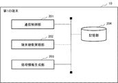
- FIG. 3 is a diagram showing an example of a processing configuration of the first terminal 10 according to the first embodiment.
- the first terminal 10 includes a communication control unit 201, a terminal function realization unit 202, a processing information generation unit 203, and a storage unit 204.
- the communication control unit 201 is a means for controlling communication with other devices. Specifically, the communication control unit 201 receives data (packets) from the server device 30. Further, the communication control unit 201 transmits data to the server device 30.
- the terminal function realization unit 202 is a means for realizing the function assigned to the first terminal 10. Specifically, when the first terminal 10 operates as a check-in terminal, the terminal function realization unit 202 executes a process related to the check-in.
- the terminal function realization unit 202 executes a process related to the face authentication when operating with the face authentication setting. Specifically, the terminal function realization unit 202 acquires a face image of the user in front of the user and calculates a feature amount. Further, when operating in the non-face authentication setting, the terminal function realization unit 202 accepts information input by the staff in charge and processes the accepted information.
- terminal function realization unit 202 changes according to the function assigned to the first terminal 10, a more detailed description regarding the realization of the function will be omitted.
- the terminal function realization unit 202 notifies the processing information generation unit 203 of the processing content each time the user's procedure is processed. For example, when the user's check-in procedure is completed, the terminal function realization unit 202 notifies the processing information generation unit 203 of the completion of the procedure together with the operation mode (face authentication setting, non-face authentication setting) at that time.
- the processing information generation unit 203 is a means for generating "processing information" to be notified to the server device 30.
- the processing information generation unit 203 counts the number of processing of the user's procedure by the terminal function realization unit 202 for each predetermined period.
- the processing information generation unit 203 transmits "processing information” including the number of users counted each time the predetermined period elapses to the server device 30. More specifically, the processing information generation unit 203 transmits "processing information" including the setting mode (face authentication setting, non-face authentication setting) of the terminal and the number of processes of the user to the server device 30.
- the storage unit 204 is a means for storing information necessary for the operation of the first terminal 10.
- the plurality of second terminals 20 are terminals installed after at least one or more first terminals 10. That is, the second terminal 20 is a terminal that provides a service to a user who has completed the procedure (service) by the first terminal 10.
- FIG. 4 is a diagram showing an example of the processing configuration of the second terminal 20 according to the first embodiment.
- the second terminal 20 includes a communication control unit 301, a terminal function realization unit 302, an operation mode switching unit 303, and a storage unit 304.
- the communication control unit 301 is a means for controlling communication with other devices. Specifically, the communication control unit 301 receives data (packets) from the server device 30. Further, the communication control unit 301 transmits data to the server device 30.
- the terminal function realization unit 302 is a means for realizing the function assigned to the second terminal 20. Specifically, when the second terminal 20 operates as a terminal related to the security check, the terminal function realization unit 302 executes the process related to the security check. Since the terminal function realization unit 302 changes according to the function assigned to the second terminal 20 like the terminal function realization unit 202 of the first terminal 10, a more detailed explanation regarding the realization of the function will be given. Omit.
- the operation mode switching unit 303 is a means for switching the operation mode of the terminal function realizing unit 302 according to the "setting switching notification" received from the server device 30.
- the operation mode switching unit 303 instructs the terminal function realization unit 302 to operate with the "face authentication setting”.
- the operation mode switching unit 303 instructs the terminal function realization unit 302 to operate with the "non-face authentication setting”.
- the storage unit 304 is a means for storing information necessary for the operation of the second terminal 20.
- the operation mode of the first terminal 10 can be set by any method.
- the administrator or the like may change the setting menu of the first terminal 10 and input the operation mode.
- the server device 30 may notify the first terminal 10 of the operation mode.
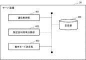
- FIG. 5 is a diagram showing an example of a processing configuration of the server device 30 according to the first embodiment.
- the server device 30 includes a communication control unit 401, a face recognition utilization rate calculation unit 402, an operation mode determination unit 403, and a storage unit 404.
- the communication control unit 401 is a means for controlling communication with other devices. Specifically, the communication control unit 401 receives data (packets) from the first terminal 10 and the second terminal 20. Further, the communication control unit 401 transmits data to the first terminal 10 and the second terminal 20.
- the face authentication utilization rate calculation unit 402 is a means for calculating the face authentication utilization rate.
- the face authentication utilization rate calculation unit 402 aggregates the processing information transmitted from each of the plurality of first terminals 10 and calculates the face authentication utilization rate per unit time. Specifically, the face authentication utilization rate calculation unit 402 sets the number of processes of each terminal to "the number of face authentication processes" and “non-face authentication process” based on the operation mode of the process information transmitted from the first terminal 10. Classify into one of "numbers”.
- the face recognition utilization rate calculation unit 402 adds the number of processes of each terminal for each operation mode, calculates the total number of face recognition processes and the total number of non-face recognition processes, and calculates the total number of these calculated numbers in the above formula (1). ) To calculate the face recognition utilization rate.
- the face authentication utilization rate calculation unit 402 delivers the calculated face authentication utilization rate to the operation mode determination unit 403.
- the operation mode determination unit 403 is a means for determining the operation mode of the second terminal 20 based on the calculated face recognition utilization rate. Specifically, the operation mode determination unit 403 determines the operation mode of at least one or more of the plurality of second terminals 20. For example, the operation mode determination unit 403 determines the operation mode of the second terminal 20 so that the number of the second terminals 20 operating in the face authentication setting increases as the face authentication utilization rate is high. On the other hand, the operation mode determination unit 403 determines the operation mode of the second terminal 20 so that the number of the second terminals 20 operating in the non-face authentication setting increases if the face authentication utilization rate is low.
- the operation mode determination unit 403 determines the operation mode of the second terminal 20 by referring to the table information in which the face authentication utilization rate and the number of the second terminals 20 to be operated by the face authentication setting are associated with each other. For example, the operation mode determination unit 403 refers to the table information as shown in FIG. 6 and determines the number of the second terminals 20 that operate in the face authentication setting according to the face authentication utilization rate. In the example of FIG. 6, if the face recognition utilization rate is 90% or more, the number of the second terminals 20 operating in the face recognition setting is set to A1. In the example of FIG. 6, A1> A2> A3.
- the operation mode determination unit 403 determines the second terminal 20 to change the operation mode. Specifically, when increasing the number of the second terminals 20 operating in the face recognition setting, the operation mode determination unit 403 increases (changes) from the second terminal 20 operating in the non-face recognition setting. Minutes) Select the number of units.
- the operation mode determination unit 403 instructs the selected second terminal 20 to change the operation mode. In the above example, the operation mode determination unit 403 transmits a setting switching notification to the selected second terminal 20 so as to operate with the face authentication setting.
- the face authentication utilization rate calculation unit 402 calculates the utilization rate of the face authentication function in at least one or more first terminals 10. Further, the operation mode determination unit 403 determines the number of terminals that provide the service by the face authentication function among the plurality of second terminals 20 based on the calculated utilization rate. More specifically, the operation mode determination unit 403 selects a terminal that needs to switch between the face authentication function and the non-face authentication function from the plurality of second terminals 20 based on the face authentication utilization rate, and the selected terminal is selected. A setting switching notification is transmitted to the second terminal 20.
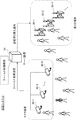
- FIG. 7 is a sequence diagram showing an example of the operation of the authentication system according to the first embodiment.
- the first terminal 10 generates processing information including the number of user processing per unit time (the number of users processed by face authentication, the number of users processed by conventional processing) (step S01).
- the first terminal 10 transmits the generated processing information to the server device 30 (step S02).
- each of the plurality of first terminals 10 is a process including the number of users who provided the service by the face authentication function or the number of users who provided the service by the non-face authentication function per unit time. Generate information. Further, each of the plurality of first terminals 10 transmits the processing information to the server device 30.
- the server device 30 aggregates the processing information acquired from the first terminal 10 and processes the total number of face recognition users (total number of face recognition processes) and the total number of non-face recognition users (non-face recognition) per unit time. Calculate the total number of processes). The server device 30 calculates the face authentication utilization rate using the total number of these (step S03).
- the server device 30 determines the operation mode of the second terminal 20 based on the face authentication utilization rate (step S04). Specifically, the server device 30 increases the number of second terminals 20 that operate with the face authentication setting if the face authentication utilization rate is high.
- the server device 30 transmits a setting switching notification to the second terminal 20 to be switched in the operation mode (step S05).
- the second terminal 20 Upon receiving the setting switching notification, the second terminal 20 switches the settings of its own device (face authentication setting, conventional processing setting) according to the notification (step S06).
- the server device 30 grasps the usage status of face authentication in the first terminal 10.
- the server device 30 determines the operation mode of the second terminal 20 belonging to the second terminal group (plurality of second terminals 20) according to the grasped usage status of face authentication. Specifically, the server device 30 increases the number of second terminals 20 that provide services by setting face recognition in a situation where face recognition is widely used. On the other hand, the server device 30 reduces the number of the second terminals 20 that provide the service by the face authentication setting if the usage status of the face authentication is low.
- the server device 30 is a rear terminal (second terminal 20) located downstream of the system according to the usage status of face recognition (biometric authentication) in the front terminal (first terminal 10) located upstream of the system. Dynamically switches the operation mode (enable biometrics, disable biometrics) in. Even if the ratio of system user attributes (face recognition users, non-users) changes significantly depending on the time of day, season, etc., the above switching optimizes the operation mode of the subsequent terminal and increases the system throughput. be able to. As a result of the increased throughput of the system, the convenience of the authentication system is improved.
- the operation mode of the second terminal 20 is determined based on the "processing information" notified from the first terminal 10.
- the operation mode of the second terminal 20 is determined based on the information obtained from the camera device installed in the field.
- FIG. 8 is a diagram showing an example of a schematic configuration of the authentication system according to the second embodiment.
- the authentication system includes camera devices 40-1 to 40-K (K is a positive integer, the same applies hereinafter), a second terminal 20, and a server device 30.
- the camera device 40 is installed in various places in the field (for example, in the airport).
- the camera device 40 is configured to be able to communicate with the server device 30 by a wired or wireless communication means.
- Each of the camera devices 40 transmits an image captured in the field to the server device 30.
- the server device 30 analyzes the acquired field image and switches the operation mode of the second terminal 20 based on the result of the analysis.
- the server device 30 when the server device 30 finds a suspicious person (a person shown in gray in FIG. 8) in the field, the server device 30 switches the operation mode of the second terminal 20 to the non-face authentication setting.
- the server device 30 finds a suspicious person, the second terminal 20 does not operate automatically (operates unattended), but switches to a non-face authentication setting that requires an operation by a staff member or the like.
- security in the field inside the airport
- the server device 30 strengthens the monitoring system in the field by increasing the number of second terminals 20 operating in the non-face authentication setting (or setting all the second terminals 20 in the non-face authentication setting). ..
- the server device 30 may switch the operation mode of the second terminal 20 to the non-face recognition setting when it finds a person who needs the support of staff such as a physically handicapped person or a pregnant woman by analyzing the field image. Good. That is, when the server device 30 finds a physically handicapped person or the like, the number of the second terminals 20 operating in the non-face authentication setting may be increased.
- the server device 30 calculates the congestion status of each procedure area (for example, in the case of an airport, the security inspection area or the boarding area) by analyzing the field image, and based on the calculated congestion status, the second terminal 20 The operation mode may be switched.
- the server device 30 included in the authentication system according to the second embodiment will be described.
- a general-purpose Web camera or the like can be used as the camera device 40.
- the second terminal 20 can be the same as the configuration and function described in the first embodiment. Therefore, detailed description of these devices will be omitted.
- FIG. 9 is a diagram showing an example of a processing configuration (processing module) of the server device 30 according to the second embodiment.
- the server device 30 includes a communication control unit 401, an operation mode determination unit 403, a storage unit 404, and an image analysis unit 405.
- the image analysis unit 405 is added instead of the face recognition utilization rate calculation unit 402.
- the image analysis unit 405 is a means for analyzing the field image acquired from the camera device 40 and notifying the operation mode determination unit 403 of the result.
- the image analysis unit 405 executes an analysis regarding whether or not a suspicious person exists in the field.
- the image analysis unit 405 extracts a person from the acquired field image and extracts the face area of the extracted person.
- the image analysis unit 405 calculates a feature amount (feature vector composed of a plurality of feature amounts) from the extracted face region (face image).
- the image analysis unit 405 compares the calculated feature amount with the feature amount in the pre-stored list (blacklist in which the feature amount of the suspicious person is described), and whether or not the calculated feature amount is registered in the blacklist. Check if.
- the image analysis unit 405 determines the operation mode as an "image analysis result" indicating that a suspicious person exists. Notify department 403. Alternatively, when the image analysis unit 405 confirms a plurality of suspicious persons, the image analysis unit 405 may notify the operation mode determination unit 403 of the number of suspicious persons as an "image analysis result".
- the image analysis unit 405 may execute, for example, an analysis regarding whether or not a physically handicapped person or a pregnant woman exists in the field. In this case, the image analysis unit 405 extracts a whole body image of the person from the field image. Specifically, the image analysis unit 405 detects a region including the whole body of the person (whole body region) from the field image. After that, the image analysis unit 405 extracts the whole body image by cutting out the detected whole body region from the field image.
- the image analysis unit 405 detects a physically handicapped person or the like by comparing the extracted whole body image with a template prepared in advance.
- the image analysis unit 405 may detect a physically handicapped person or the like using a learning model generated by machine learning. For example, a large number of images of physically handicapped persons with labels are prepared as teacher data, and a learning model is generated using the teacher data. Any algorithm such as support vector machine, boosting or neural network can be used to generate the training model. Since a known technique can be used for the algorithm such as the support vector machine, the description thereof will be omitted.
- the image analysis unit 405 When the image analysis unit 405 detects a physically handicapped person or the like in the field, the image analysis unit 405 notifies the operation mode determination unit 403 as an "image analysis result" to that effect. Alternatively, when the image analysis unit 405 detects a plurality of physically handicapped persons or the like, the image analysis unit 405 may notify the operation mode determination unit 403 of the number as an “image analysis result”.
- the operation mode determination unit 403 is a means for switching the operation mode in the second terminal 20 based on the image analysis result acquired from the image analysis unit 405.
- the operation mode determination unit 403 increases the number of the second terminals 20 that operate in the non-face authentication setting if there is a suspicious person, a physically handicapped person, or the like in the field.
- the operation mode determination unit 403 may set the operation modes of all the second terminals 20 as non-face authentication settings.
- the operation mode determination unit 403 may determine the operation mode of the second terminal 20 according to the number of suspicious persons, physically handicapped persons, and the like. For example, the operation mode determination unit 403 may increase the number of the second terminals 20 that operate in the non-face authentication setting as the number of suspicious persons and the like increases.
- the security in the airport is strengthened by analyzing the field image acquired from the camera device 40, and the service suitable for the physically handicapped or the like is provided. can do.
- FIG. 10 is a diagram showing an example of the hardware configuration of the server device 30.
- the server device 30 can be configured by an information processing device (so-called computer), and includes the configuration illustrated in FIG.
- the server device 30 includes a processor 311, a memory 312, an input / output interface 313, a communication interface 314, and the like.
- the components such as the processor 311 are connected by an internal bus or the like so that they can communicate with each other.
- the configuration shown in FIG. 10 does not mean to limit the hardware configuration of the server device 30.
- the server device 30 may include hardware (not shown) or may not include an input / output interface 313 if necessary.
- the number of processors 311 and the like included in the server device 30 is not limited to the example shown in FIG. 10, and for example, a plurality of processors 311 may be included in the server device 30.
- the processor 311 is a programmable device such as a CPU (Central Processing Unit), an MPU (Micro Processing Unit), and a DSP (Digital Signal Processor). Alternatively, the processor 311 may be a device such as an FPGA (Field Programmable Gate Array) or an ASIC (Application Specific Integrated Circuit). The processor 311 executes various programs including an operating system (OS).
- OS operating system
- the memory 312 is a RAM (RandomAccessMemory), a ROM (ReadOnlyMemory), an HDD (HardDiskDrive), an SSD (SolidStateDrive), or the like.
- the memory 312 stores an OS program, an application program, and various data.
- the input / output interface 313 is an interface of a display device or an input device (not shown).
- the display device is, for example, a liquid crystal display or the like.
- the input device is, for example, a device that accepts user operations such as a keyboard and a mouse.
- the communication interface 314 is a circuit, module, or the like that communicates with another device.
- the communication interface 314 includes a NIC (Network Interface Card) and the like.
- the function of the server device 30 is realized by various processing modules.
- the processing module is realized, for example, by the processor 311 executing a program stored in the memory 312.
- the program can also be recorded on a computer-readable storage medium.
- the storage medium may be a non-transient such as a semiconductor memory, a hard disk, a magnetic recording medium, or an optical recording medium. That is, the present invention can also be embodied as a computer program product.
- the program can be downloaded via a network or updated using a storage medium in which the program is stored.
- the processing module may be realized by a semiconductor chip.
- the first terminal 10 and the second terminal 20 can also be configured by an information processing device like the server device 30, and the basic hardware configuration thereof is not different from that of the server device 30, so the description thereof is omitted. To do.
- the first terminal 10 and the second terminal 20 may be provided with a camera device (camera module) or the like, if necessary.
- the authentication system may include one or more first terminals 10. Just do it.
- the first terminal 10 may be a hybrid type terminal. That is, the first terminal 10 does not require a setting change, and is configured to be capable of both providing a service by the face authentication function and providing a service by the non-face authentication function.
- the first terminal 10 calculates the number of face authentication processes and the number of non-face authentication processes in a unit time, and reports the number to the server device 30.
- the server device 30 may calculate the face authentication utilization rate using the number of these processes.
- biometric information that can be used in the disclosure of the present application is not limited to "face”.
- other biological information such as the iris can be used.
- the face authentication usage rate is used as an index for grasping the usage status of face authentication in the previous stage terminal (first terminal 10)
- the above usage status can be grasped by other indexes. It may be done.
- the non-face recognition utilization rate (percentage of users whose services are provided by a conventional procedure) in the first terminal 10 may be calculated. Since the face recognition usage rate and the non-face recognition usage rate are inextricably linked, the non-face recognition usage rate can be regarded as the face recognition usage rate.
- the second terminal 20 has been described as a terminal in the subsequent stage, but depending on the system configuration, the second terminal 20 may operate as a terminal in the previous stage.
- the second terminal 20 may include the function of the first terminal 10. That is, a processing module corresponding to the "processing information generation unit 203" is mounted on the second terminal 20, and the processing information is transmitted from the second terminal 20 to the server device 30.
- the server device 30 may calculate the face authentication utilization rate (the usage status of face authentication in the second terminal 20) based on the processing information transmitted from the second terminal 20, and determine the operation mode of the subsequent terminal. ..
- a terminal that provides a service by a face recognition setting or a non-face recognition setting has been described as an example, but the terminal provides a service by both face recognition and non-face recognition in addition to the above two settings. It may be possible to set a hybrid terminal to be used. That is, the first terminal 10, the second terminal 20, and the second terminal 20 in the second embodiment have three operation modes of face authentication setting, non-face authentication setting, and hybrid setting. It may be switchable.
- the determination of the number is performed by using a predetermined function or the like. It may be decided. For example, a function for inputting the face recognition utilization rate and outputting the number of second terminals 20 operating in the face recognition setting is defined in advance, and the number of second terminals 20 operating in the face recognition setting using the function is defined in advance. May be determined.
- the number of second terminals 20 that operate with the optimum face recognition setting for each face recognition utilization rate is prepared in advance as teacher data, and the learning model constructed using the teacher data is used to operate with the face recognition setting.
- the number of second terminals 20 to be used may be calculated. Any algorithm such as a support vector machine, boosting, or neural network can be used to generate the training model. Since a known technique can be used for the algorithm such as the support vector machine, the description thereof will be omitted.
- the server device 30 may change the setting of the first terminal group based on the face authentication utilization rate in the first terminal group.
- the computer By installing the terminal operation determination program in the storage unit of the computer, the computer can function as the server device 30. Further, by causing the computer to execute the terminal operation determination program, the terminal operation determination method can be executed by the computer.
- each embodiment may be used alone or in combination. For example, it is possible to replace a part of the configuration of the embodiment with the configuration of another embodiment, or to add the configuration of another embodiment to the configuration of the embodiment. Further, it is possible to add, delete, or replace a part of the configuration of the embodiment with another configuration.
- the present invention is suitably applicable to an authentication system in an airport or the like.
- An authentication system that determines the operation mode of at least one or more of the plurality of second terminals (20, 102) based on the calculated utilization rate.
- Appendix 2 The authentication system according to claim 1, wherein the server device (30, 103) determines the number of terminals that provide a service by a biometric authentication function among the plurality of second terminals (20, 102).
- Appendix 3 The server devices (30, 103) Based on the utilization rate, a terminal that needs to switch between the biometric authentication function and the non-biometric authentication function is selected from the plurality of second terminals (20, 102), and the selected second terminal (20, 102) is selected. ), The authentication system according to Appendix 1 or 2.
- Appendix 4 A plurality of the first terminals (10, 101) are included.
- Each of the plurality of first terminals (10, 101) includes the number of users who provided the service by the biometric authentication function or the number of users who provided the service by the non-biometric authentication function per unit time.
- the authentication system according to any one of Supplementary notes 1 to 3, which generates processing information.
- [Appendix 5] The authentication system according to Appendix 4, wherein each of the plurality of first terminals (10, 101) transmits the processing information to the server device (30, 103).
- the server device (30, 103) was processed per unit time by the first terminal (10, 101) of the plurality of first terminals (10, 101), which provides a service by the bioauthentication function.
- the server devices (30, 103) provide the service by the total number of users who provided the service by the biometric authentication function, the total number of users who provided the service by the biometric authentication function, and the non-biometric authentication function.
- Appendix 9 The authentication according to any one of Supplementary Provisions 1 to 8, wherein the plurality of second terminals (20, 102) are terminals installed after the at least one or more first terminals (10, 101). system.
- Appendix 10 The authentication system according to any one of Supplementary Provisions 1 to 9, wherein the at least one or more first terminals (10, 101) are terminals that execute processing related to a check-in procedure.
- the utilization rate of the biometric authentication function in the at least one or more first terminals (10, 101) is calculated, and the utilization rate is calculated.
- Appendix 12 and the form of Appendix 13 can be expanded to the forms of Appendix 2 to the form of Appendix 11 in the same manner as the form of Appendix 1.
Abstract
L'invention concerne un système d'authentification qui améliore la commodité de l'utilisateur. Ce système d'authentification comprend au moins un premier terminal, une pluralité de seconds terminaux, et un dispositif serveur. Le premier terminal est susceptible de fournir des services à l'aide d'une fonction d'authentification biométrique ou d'une fonction d'authentification non biométrique. Chacun des seconds terminaux est susceptible de commuter entre une fonction d'authentification biométrique et une fonction d'authentification non biométrique et susceptible de fournir des services à l'aide de la fonction d'authentification biométrique ou de la fonction d'authentification non biométrique. Le dispositif serveur est connecté au premier terminal et à la pluralité de seconds terminaux. Le dispositif serveur calcule le taux d'utilisation d'une fonction d'authentification biométrique par lesdits premier terminal. Le dispositif serveur détermine un mode de fonctionnement d'au moins un second terminal de la pluralité de seconds terminaux sur la base du taux d'utilisation calculé.
Priority Applications (4)
| Application Number | Priority Date | Filing Date | Title |
|---|---|---|---|
| US17/784,734 US20230011336A1 (en) | 2019-12-26 | 2019-12-26 | Authentication system, method, and computer-readable recording medium |
| JP2021566674A JP7264279B2 (ja) | 2019-12-26 | 2019-12-26 | 認証システム、方法及びプログラム |
| EP19958026.7A EP4083827A4 (fr) | 2019-12-26 | 2019-12-26 | Système, procédé et programme d'authentification |
| PCT/JP2019/051075 WO2021130948A1 (fr) | 2019-12-26 | 2019-12-26 | Système, procédé et programme d'authentification |
Applications Claiming Priority (1)
| Application Number | Priority Date | Filing Date | Title |
|---|---|---|---|
| PCT/JP2019/051075 WO2021130948A1 (fr) | 2019-12-26 | 2019-12-26 | Système, procédé et programme d'authentification |
Publications (1)
| Publication Number | Publication Date |
|---|---|
| WO2021130948A1 true WO2021130948A1 (fr) | 2021-07-01 |
Family
ID=76573770
Family Applications (1)
| Application Number | Title | Priority Date | Filing Date |
|---|---|---|---|
| PCT/JP2019/051075 WO2021130948A1 (fr) | 2019-12-26 | 2019-12-26 | Système, procédé et programme d'authentification |
Country Status (4)
| Country | Link |
|---|---|
| US (1) | US20230011336A1 (fr) |
| EP (1) | EP4083827A4 (fr) |
| JP (1) | JP7264279B2 (fr) |
| WO (1) | WO2021130948A1 (fr) |
Cited By (1)
| Publication number | Priority date | Publication date | Assignee | Title |
|---|---|---|---|---|
| JP7363981B2 (ja) | 2022-02-14 | 2023-10-18 | 日本電気株式会社 | システム、サーバ装置、サーバ装置の制御方法及びプログラム |
Citations (4)
| Publication number | Priority date | Publication date | Assignee | Title |
|---|---|---|---|---|
| JP2007079656A (ja) * | 2005-09-12 | 2007-03-29 | Hitachi Ltd | チケットレス搭乗システム及びチケットレス搭乗方法 |
| JP2008507790A (ja) * | 2004-07-26 | 2008-03-13 | ディズニー エンタープライゼス インコーポレイテッド | 運行設備に対する乗客、手荷物及び貨物の流れの管理 |
| WO2009075180A1 (fr) * | 2007-12-11 | 2009-06-18 | Nec Corporation | Dispositif d'authentification, système d'authentification, procédé d'authentification et programme |
| JP2019124999A (ja) * | 2018-01-12 | 2019-07-25 | 日本電気株式会社 | 顔認証装置 |
Family Cites Families (3)
| Publication number | Priority date | Publication date | Assignee | Title |
|---|---|---|---|---|
| US10136320B1 (en) * | 2017-11-22 | 2018-11-20 | International Business Machines Corporation | Authentication of users at multiple terminals |
| WO2020075280A1 (fr) * | 2018-10-11 | 2020-04-16 | 日本電気株式会社 | Dispositif de traitement d'informations, procédé de traitement d'informations et support d'enregistrement |
| EP3787225A4 (fr) * | 2019-04-10 | 2021-12-22 | Rakuten Group, Inc. | Système d'authentification, terminal d'authentification, terminal utilisateur, procédé d'authentification et programme |
-
2019
- 2019-12-26 US US17/784,734 patent/US20230011336A1/en active Pending
- 2019-12-26 JP JP2021566674A patent/JP7264279B2/ja active Active
- 2019-12-26 EP EP19958026.7A patent/EP4083827A4/fr not_active Withdrawn
- 2019-12-26 WO PCT/JP2019/051075 patent/WO2021130948A1/fr unknown
Patent Citations (4)
| Publication number | Priority date | Publication date | Assignee | Title |
|---|---|---|---|---|
| JP2008507790A (ja) * | 2004-07-26 | 2008-03-13 | ディズニー エンタープライゼス インコーポレイテッド | 運行設備に対する乗客、手荷物及び貨物の流れの管理 |
| JP2007079656A (ja) * | 2005-09-12 | 2007-03-29 | Hitachi Ltd | チケットレス搭乗システム及びチケットレス搭乗方法 |
| WO2009075180A1 (fr) * | 2007-12-11 | 2009-06-18 | Nec Corporation | Dispositif d'authentification, système d'authentification, procédé d'authentification et programme |
| JP2019124999A (ja) * | 2018-01-12 | 2019-07-25 | 日本電気株式会社 | 顔認証装置 |
Non-Patent Citations (1)
| Title |
|---|
| See also references of EP4083827A4 * |
Cited By (1)
| Publication number | Priority date | Publication date | Assignee | Title |
|---|---|---|---|---|
| JP7363981B2 (ja) | 2022-02-14 | 2023-10-18 | 日本電気株式会社 | システム、サーバ装置、サーバ装置の制御方法及びプログラム |
Also Published As
| Publication number | Publication date |
|---|---|
| EP4083827A4 (fr) | 2022-12-14 |
| EP4083827A1 (fr) | 2022-11-02 |
| JPWO2021130948A1 (fr) | 2021-07-01 |
| JP7264279B2 (ja) | 2023-04-25 |
| US20230011336A1 (en) | 2023-01-12 |
Similar Documents
| Publication | Publication Date | Title |
|---|---|---|
| US11616804B2 (en) | Thwarting model poisoning in federated learning | |
| Kolhar et al. | A three layered decentralized IoT biometric architecture for city lockdown during COVID-19 outbreak | |
| Monrose et al. | Keystroke dynamics as a biometric for authentication | |
| WO2019200781A1 (fr) | Procédé et dispositif de reconnaissance de reçu, et support de stockage | |
| Yasir et al. | Two-handed hand gesture recognition for Bangla sign language using LDA and ANN | |
| EP3452952A1 (fr) | Classificateurs spécifiques à un utilisateur pour une détection d'activité biométrique | |
| Hu et al. | A pervasive EEG-based biometric system | |
| CN111149104A (zh) | 用于生物特征识别的装置、方法和计算机程序产品 | |
| Kumar et al. | Integrating palmprint with face for user authentication | |
| CN109274683A (zh) | 一种交叉组合认证系统及其认证方法 | |
| Gale et al. | Evolution of performance analysis of iris recognition system by using hybrid methods of feature extraction and matching by hybrid classifier for iris recognition system | |
| WO2021130948A1 (fr) | Système, procédé et programme d'authentification | |
| Thenuwara et al. | A multi-agent based enhancement for multimodal biometric system at border control | |
| WO2021175010A1 (fr) | Appareil et procédé d'identification de sexe, dispositif électronique et support de stockage | |
| CN114187561A (zh) | 异常行为的识别方法、装置、终端设备及存储介质 | |
| Sang et al. | Novel impostors detection in keystroke dynamics by support vector machine | |
| Boka et al. | Person recognition for access logging | |
| Agbinya et al. | Design and implementation of multimodal digital identity management system using fingerprint matching and face recognition | |
| Alghamdi et al. | Artificial intelligence Techniques based learner authentication in cybersecurity higher education institutions | |
| Tang et al. | Face recognition committee machines: dynamic vs. static structures. | |
| Kaur et al. | Automatic Attendance System Using AI and Raspberry Pi Controller | |
| CN111807173A (zh) | 基于深度学习的电梯控制方法、电子设备及存储介质 | |
| Lumini et al. | Over-complete feature generation and feature selection for biometry | |
| Kanimozhi et al. | Identification of Non-Vaccinated People Using Face Recognition Based on CNN | |
| Shyry | Biometric-based three-tier microservice architecture for mitigating the fraudulent behaviour |
Legal Events
| Date | Code | Title | Description |
|---|---|---|---|
| 121 | Ep: the epo has been informed by wipo that ep was designated in this application |
Ref document number: 19958026 Country of ref document: EP Kind code of ref document: A1 |
|
| ENP | Entry into the national phase |
Ref document number: 2021566674 Country of ref document: JP Kind code of ref document: A |
|
| NENP | Non-entry into the national phase |
Ref country code: DE |
|
| ENP | Entry into the national phase |
Ref document number: 2019958026 Country of ref document: EP Effective date: 20220726 |