WO2021117663A1 - スピーカ - Google Patents
スピーカ Download PDFInfo
- Publication number
- WO2021117663A1 WO2021117663A1 PCT/JP2020/045415 JP2020045415W WO2021117663A1 WO 2021117663 A1 WO2021117663 A1 WO 2021117663A1 JP 2020045415 W JP2020045415 W JP 2020045415W WO 2021117663 A1 WO2021117663 A1 WO 2021117663A1
- Authority
- WO
- WIPO (PCT)
- Prior art keywords
- diaphragm
- voice coil
- neck portion
- adhesive
- neck
- Prior art date
- Legal status (The legal status is an assumption and is not a legal conclusion. Google has not performed a legal analysis and makes no representation as to the accuracy of the status listed.)
- Ceased
Links
Images


Classifications
-
- H—ELECTRICITY
- H04—ELECTRIC COMMUNICATION TECHNIQUE
- H04R—LOUDSPEAKERS, MICROPHONES, GRAMOPHONE PICK-UPS OR LIKE ACOUSTIC ELECTROMECHANICAL TRANSDUCERS; ELECTRIC HEARING AIDS; PUBLIC ADDRESS SYSTEMS
- H04R7/00—Diaphragms for electromechanical transducers; Cones
- H04R7/16—Mounting or tensioning of diaphragms or cones
-
- H—ELECTRICITY
- H04—ELECTRIC COMMUNICATION TECHNIQUE
- H04R—LOUDSPEAKERS, MICROPHONES, GRAMOPHONE PICK-UPS OR LIKE ACOUSTIC ELECTROMECHANICAL TRANSDUCERS; ELECTRIC HEARING AIDS; PUBLIC ADDRESS SYSTEMS
- H04R9/00—Transducers of moving-coil, moving-strip, or moving-wire type
- H04R9/02—Details
- H04R9/04—Construction, mounting, or centering of coil
Definitions
- This disclosure relates to a speaker, which is a type of audio equipment.
- the vibration system of the speaker is a cylindrical voice coil bobbin around which a voice coil placed in a magnetic field is wound, a damper that vibrates this voice coil bobbin, and a voice coil bobbin that is connected to the upper part of the voice coil bobbin via an adhesive. It is composed of a diaphragm that transmits vibrations.
- paper has been used as the diaphragm material for speakers. Paper has a relatively high speed of sound due to its low density, moderate rigidity, and internal loss, and it is easy to obtain good strain characteristics. In addition, since paper is easily penetrated by an adhesive, it has an advantage that high adhesive strength can be obtained.
- resin diaphragms have come to be adopted in order to obtain diaphragms with high rigidity, good water resistance and moisture resistance, and stable quality.
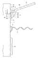
- Patent Document 1 describes a coupling configuration of a diaphragm and a voice coil having the configuration shown in FIG. 8 in a conventional example.
- Patent Document 1 as a structure for improving the problem that the voice coil falls off from the diaphragm, which is a problem of the conventional example shown in FIG. 8, a structure in which a plurality of protrusions are provided at the joint portion between the diaphragm and the voice coil. Is disclosed.
- this method has a problem that the structure of the diaphragm and the voice coil bobbin becomes complicated, and the work of fitting the protrusions to each other at the time of assembly is added, so that both parts and manufacturing are costly.
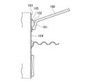
- Patent Document 2 is a speaker made of polypropylene resin.
- FIG. 9 shows the configuration.
- Patent Document 2 a folded-back 101a is formed on the outer side of the lower end of the inner peripheral rising portion of the neck portion of the diaphragm 100, a damper 106 is positioned at this portion, and a voice coil bobbin 103 and a neck portion 101 of the diaphragm 100 are used by using an adhesive 105. , The damper 106 is adhered to.
- the position where the diaphragm 100 and the damper 106 are adhered to the voice coil bobbin must be close to each other, and there is a design requirement that the diaphragm 100 and the damper 106 should be separated from each other. There is a problem that it cannot be adopted.
- the door when attached to a car door, the door is opened and closed complicatedly, and at that time, if the door is roughly closed, the vibration plate 100 is peeled off from the outer peripheral surface 104 of the voice coil bobbin 103 due to the impact, and the neck is pulled out and falls off. There is also the problem of closing it.
- the present disclosure has been proposed in view of the above, and the purpose of the present disclosure is to enable reliable and strong adhesion to the voice coil bobbin even if the diaphragm is made of resin, and to realize high input resistance.
- the purpose of the present invention is to provide a speaker that prevents the diaphragm from falling off from the voice coil bobbin.
- the neck portion of the diaphragm is bonded to the voice coil bobbin with an adhesive
- the neck portion is formed at the central opening of the diaphragm so as to project toward the back surface of the diaphragm.
- An adhesive receiver in which a gap is formed between the outer peripheral surface of the voice coil bobbin and the inner peripheral surface of the neck portion, and the upper surface of the neck portion is located below the front surface of the outer peripheral portion of the diaphragm to form a dent.
- the adhesive is provided with a portion, and the adhesive is filled in the adhesive receiving portion and the gap, reaches the lower end portion of the neck portion, and fixes the neck portion and the outer peripheral surface of the voice coil bobbin. ..
- the inner peripheral surface of the neck portion has a vertical surface on the upper surface side of the neck portion, and is inclined downward to the outer peripheral side of the diaphragm and expands downward. It is characterized by having a diameter-expanded surface having a diameter.
- the present disclosure according to claim 3 is characterized in that a neck groove is formed in the adhesive receiving portion in the speaker.
- a plurality of ribs protruding toward the outer peripheral surface of the voice coil bobbin and abutting on the outer peripheral surface of the voice coil bobbin are formed at equal intervals on the inner peripheral surface of the neck portion. It is characterized by that.
- the lower portion of the neck portion is formed to be thicker than the outer peripheral portion of the diaphragm, and the lower end inner peripheral portion of the lower portion of the neck portion is the inner peripheral surface of the neck portion. It is characterized in that it is formed by a continuous curved surface.
- a neck portion is formed so as to project toward the back surface of the vibrating plate at the central opening of the vibrating plate, and a gap is formed between the outer peripheral surface of the voice coil bobbin and the inner peripheral surface of the neck portion.
- the upper surface of the neck portion is located below the front surface of the outer peripheral portion of the vibrating plate and is provided with an adhesive receiving portion that becomes a recess, and the adhesive is filled in the adhesive receiving portion and the gap and the lower end portion of the neck portion.
- the adhesive flows through the gap between the outer peripheral surface of the voice coil bobbin and the inner peripheral surface of the neck portion, reaches the lower end portion, and reaches the lower end portion from the adhesive receiving portion to the lower end portion of the neck portion. Since the receiving portion and the lower end portion can be sandwiched and fixed with an adhesive, the input resistance can be improved and the diaphragm can be prevented from falling off from the voice coil. According to the present disclosure according to claim 2, since the lower part of the inner peripheral surface of the neck portion is a diameter-expanded surface that expands and inclines so as to expand the diameter toward the outer peripheral side of the diaphragm, the adhesive that has entered through the gap expands. Easy to flow along the radial surface.
- the adhesive is sufficiently filled between the outer peripheral surface of the voice coil bobbin and the inner peripheral surface of the neck, and the neck is wrapped in the adhesive from the upper surface to the lower end, so that the diaphragm is securely and firmly attached to the voice coil bobbin. Can be glued. Therefore, the input resistance is improved, and it is possible to prevent the neck from falling off due to peeling.
- the adhesive flows through the neck groove of the adhesive receiving portion, and the adhesive is cured according to the shape of the neck groove, so that the diaphragm and the voice coil bobbin are more firmly formed. Can be glued.
- the voice coil bobbin can be easily and quickly set in a predetermined position via the rib, the gap between the voice coil bobbin and the neck becomes constant, and the amount of the adhesive applied becomes constant. , A uniform adhesive force can be obtained.
- the lower portion of the neck portion is formed to be thicker than the outer peripheral portion of the diaphragm, the strength of the neck portion can be improved and deformation can be prevented, and the adhesive is continuously applied to the inner peripheral surface of the neck portion. Due to the curved surface, it wraps around to the inner circumference of the lower end due to surface tension, and the neck and voice coil bobbin can be securely adhered.
- a cross-sectional view of a main part of the first embodiment of the present disclosure Same as above.
- the cross-sectional view of the main part of the 2nd Example of this disclosure The same as above, perspective view of the main part.
- Cross-sectional view of the main part. A side sectional view of a conventional example. Side sectional view of another conventional example.
- FIG. 1 is a cross-sectional view on the main part side of the first embodiment of the present disclosure
- FIG. 2 is a partially enlarged view thereof.
- 1 is a cylindrical voice coil bobbin.
- a neck portion 3 formed in a central opening 2a formed in the center of the cone-shaped diaphragm 2 is connected to the upper portion 1a of the voice coil bobbin 1 via an adhesive 4.
- the material used for the diaphragm 2 may be a synthetic resin, for example, a polypropylene resin.
- Polypropylene resin is excellent in moisture resistance and water resistance. Further, there is an advantage that the thickness is uniform at the manufacturing stage and the thickness can be easily controlled.
- the polypropylene resin may contain additives such as reinforcing fibers and mica.
- the neck portion 3 is formed in the process of punching the central portion of the diaphragm from the front side of the diaphragm toward the back surface of the diaphragm via a mold (not shown).
- the neck portion 3 is projected so as to project the central opening 2a of the diaphragm 2 toward the back surface of the diaphragm 2, that is, downward in the state shown in the drawing.
- the neck portion 3 is projected toward the back surface side of the diaphragm, and extends downward to the first neck portion 3a having a thickness substantially equal to the thickness of the outer peripheral portion of the diaphragm 2, and the first neck portion 3a and the diaphragm. It has a second neck portion 3b, which is thicker than the plate thickness of the outer peripheral portion of 2.
- the second neck portion 3b has a thick shape in which the first neck portion 3a is folded upward and overlapped, and the first neck portion 3a is added twice to increase the thickness.
- the neck portion 3 of the diaphragm 2 which is the joint portion with the voice coil bobbin 1 is formed in a substantially inverted triangular shape in the side cross section, and the thickness is made larger than the other portion which is the thickness of the outer peripheral portion of the diaphragm 2.
- the shape is thick and the strength is increased.
- the upper surface 3d of the second neck portion 3b is provided at a position lower than the front surface 2b, which is the sound radiation surface of the diaphragm 2.
- the first neck portion 3a falls like a cliff, descends and inclines due to a steeper slope from the outer peripheral side to the inner peripheral side of the diaphragm 2, and the outer peripheral portion of the diaphragm 2 and the second neck portion 3b Connect with.
- an adhesive receiving portion 5 which is a recessed space having a difference in dimension L1 in the height direction is formed between the front surface 2b of the outer peripheral portion of the diaphragm and the upper surface 3d of the second neck portion 3b.
- the adhesive receiving portion 5 is provided over the entire circumference along the outer peripheral surface 1b of the voice coil bobbin 1. Further, when the adhesive 4 is applied, the adhesive receiving portion 5 has a space formed by the upper surface 3d and the first neck portion 3a in the region facing the outer peripheral surface 1b of the voice coil bobbin 1. , Adhesive pool.
- a neck groove 3c is formed on the diaphragm 2 side, which is the outer peripheral side of the upper surface 3d of the second neck portion 3b.
- the surface area of the adhesive receiving portion 5 is increased by the neck groove 3c, and the adhesive area is increased by pouring the adhesive 4 into the neck groove 3c.
- the adhesive strength 4 is filled in the gap g on the inner peripheral surface 3k side of the neck portion 3 and the adhesive 4 filled in the neck groove 3c side sandwiches the vicinity of the upper surface 3d of the second neck portion 3b. Is improving.
- the material thickness of the upper surface 3d of the second neck portion 3b (the thickness in the radial direction excluding the neck groove 3c) is substantially the same as the thickness of the outer peripheral portion of the diaphragm 2.
- the vertical surface 3j shown by the portion of the dimension L2 shown by the alternate long and short dash line is pulled out substantially vertically because it is pulled out by the mold, and faces the outer peripheral surface 1b of the voice coil bobbin 1 in parallel with a gap g.
- the adhesive 4 sandwiches the portion facing in parallel and the portion in the height direction of the portion where the neck groove 3c is formed in the vicinity of the upper surface 3d of the second neck portion 3b from both sides. ..
- the gap g and the neck groove 3c are formed over the entire circumferential direction of the diaphragm 2, and the upper surface 3d of the second neck 3b is also sandwiched by the adhesive 4 over the entire circumferential direction.
- the gap g varies depending on the diameter of the speaker, but it is preferable to set it to approximately 0.2 mm to 0.5 mm.
- the acrylic adhesive 4 enters the portion of the gap g.
- the adhesive 4 has a viscosity of 1500 (mPa ⁇ s) or more and 8000 (mPa ⁇ s) or less.
- the adhesive 4 flows from the gap g toward the lower end of the second neck portion 3b. If the viscosity is 1500 (mPa ⁇ s) or less, the adhesive 4 may flow away. If it is 8000 (mPa ⁇ s) or more, the flow speed is slow and there is a risk of curing in the middle, so the viscosity range was set as described above.
- the inner peripheral surface of the portion of the upper surface 3d of the second neck portion 3b shown by the dimension L2 below the plate thickness is the vertical line a parallel to the outer peripheral surface 1b of the voice coil bobbin 1 in the state shown in FIG.
- a diameter-expanded surface 3e is formed that inclines and expands to the outer peripheral side as it goes downward in a range of an angle of approximately 2 ° from 3f to an angle of 10 ° of 3g.
- the angle of the enlarged diameter surface 3e was set in the range of 2 ° to 10 ° because the outer peripheral surface 1b of the voice coil bobbin 1 and the inner circumference of the central opening 2a of the diaphragm 2 were set.
- the adhesive 4 applied to the gap g with the surface gradually increases as the adhesive 4 goes to the lower end due to its own weight, so that the adhesive 4 easily flows in.
- the adhesive 4 quickly reaches from the rounded lower end inner peripheral portion 3n to the lower end portion 3h, which is formed by bulging due to the curved surface continuous with the inner peripheral surface 3k due to surface tension, so that the adhesive 4 wraps around. Is.
- the lower end inner peripheral portion 3n has a contour formed by a continuous curved surface without a portion such as a corner portion, and has a rounded and bulging shape, and does not hinder the flow of the adhesive. Further, the radius of the lower end inner peripheral portion 3n is preferably set to 0.2 mm to 0.5 mm because the adhesive wraps around.
- the angle of the enlarged diameter surface 3e is in the range of 2 ° to 10 ° so that the adhesive wraps around and reaches the lower end 3h of the neck depending on the viscosity of the adhesive used and the size of the gap g. It will be adjusted accordingly.
- the neck portion 3 is formed by the adhesive 4 applied to the upper surface 3d to the neck groove 3c portion of the second neck portion 3b and the adhesive 4 reaching the lower end portion 3h of the second neck portion 3b. Is wrapped by the adhesive 4, and the neck portion 3 and the outer peripheral surface 1b of the voice coil bobbin 1 are fixed to each other. In this way, the diaphragm 2 can be firmly and firmly adhered to the voice coil bobbin 1.
- the voice coil bobbin 1 around which the voice coil 6 is wound is connected to the inner peripheral portion of the damper 7 via the adhesive 4, and the voice coil bobbin 1 can vibrate via the damper 7. Supported by.
- FIG. 3 shows a state in which the voice coil bobbin 1 is arranged with a gap g in the central opening 2a of the diaphragm 2.
- the voice coil bobbin 1 is provided at the center position of the central opening 2a of the diaphragm via a jig (not shown).
- 8 is a magnetic circuit.
- the voice coil 6 shown in FIG. 1 is arranged in the magnetic gap (not shown) of the magnetic circuit 8.
- the diaphragm 2 vibrates.
- the neck portion 3 of the diaphragm 2 is firmly and firmly adhered to the voice coil bobbin 1 in a state of being sandwiched by the adhesive 4, the input resistance is improved and even by an impact. It will not drop out.
- Table 1 shows the comparison results of the input resistance test of the diaphragm neck pull-out between the conventional structure shown in FIG. 8 and the embodiment of the present disclosure shown in FIG.
- the neck was pulled out in 0.5 hours, but in the example, the neck was not pulled out even after 200 hours, and the durability was improved.
- the main conditions other than those shown in Table 1 are that the dimension L1 between the front surface 2b of the outer peripheral portion of the diaphragm and the upper surface 3d of the second neck portion 3b is 1.5 mm.
- the dimension L2 of the vertical surface 3j was 1 mm
- the radial dimension of the gap g was 0.3 mm
- the radius of the lower end inner peripheral portion 3n was 0.3 mm
- the viscosity of the acrylic adhesive was 3000 mPa ⁇ s.
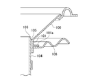
- FIG. 4 shows a second embodiment of the present disclosure.
- This embodiment is characterized in that a plurality of ribs 9 are formed on the inner peripheral surface of the second neck portion 3b so as to project toward the outer peripheral surface 1b of the voice coil bobbin 1 and are arranged at equal intervals in the circumferential direction.
- the rib 9 functions for positioning when the voice coil bobbin 1 is inserted into the central opening 2a of the diaphragm 2, and the voice coil bobbin 1 can be easily and quickly arranged at the central position.
- the gap g between the inner peripheral surface 3k of the neck portion 3 of the diaphragm 2 and the outer peripheral surface 1b of the voice coil bobbin 1 becomes uniform, the amount of the adhesive 4 applied becomes constant, and the adhesive force becomes uniform over the entire circumference of the voice coil bobbin. Therefore, the adhesive strength is improved.
- the number of ribs 9 is preferably 4 or more at equal intervals, but may be 3 or more.
- FIG. 5 is a perspective view of a main part of the second embodiment, showing a state in which four ribs 9 are projected on the inner peripheral surface 3k of the second neck portion 3b of the diaphragm 2.
- FIG. 6 shows a state in which the rib 9 projecting from the inner peripheral surface 3k of the second neck portion 3b is in contact with the outer peripheral surface 1b of the voice coil bobbin 1 inserted into the central opening 2a.
- FIG. 7 is a cross-sectional view of a main part of FIG. Similar to the first embodiment shown in FIG. 2, the inner peripheral side of the neck portion 3 is firmly wrapped by the adhesive 4, and the neck portion 3 can be firmly adhered to the voice coil bobbin 1.
Landscapes
- Engineering & Computer Science (AREA)
- Physics & Mathematics (AREA)
- Acoustics & Sound (AREA)
- Signal Processing (AREA)
- Multimedia (AREA)
- Audible-Bandwidth Dynamoelectric Transducers Other Than Pickups (AREA)
- Diaphragms For Electromechanical Transducers (AREA)
Priority Applications (1)
| Application Number | Priority Date | Filing Date | Title |
|---|---|---|---|
| JP2021563940A JP7711347B2 (ja) | 2019-12-09 | 2020-12-07 | スピーカ |
Applications Claiming Priority (2)
| Application Number | Priority Date | Filing Date | Title |
|---|---|---|---|
| JP2019-221860 | 2019-12-09 | ||
| JP2019221860 | 2019-12-09 |
Publications (1)
| Publication Number | Publication Date |
|---|---|
| WO2021117663A1 true WO2021117663A1 (ja) | 2021-06-17 |
Family
ID=76328977
Family Applications (1)
| Application Number | Title | Priority Date | Filing Date |
|---|---|---|---|
| PCT/JP2020/045415 Ceased WO2021117663A1 (ja) | 2019-12-09 | 2020-12-07 | スピーカ |
Country Status (2)
| Country | Link |
|---|---|
| JP (1) | JP7711347B2 (https=) |
| WO (1) | WO2021117663A1 (https=) |
Citations (3)
| Publication number | Priority date | Publication date | Assignee | Title |
|---|---|---|---|---|
| KR100666154B1 (ko) * | 2005-09-23 | 2007-01-09 | 에스텍 주식회사 | 스피커 |
| JP2007110209A (ja) * | 2005-10-11 | 2007-04-26 | Matsushita Electric Ind Co Ltd | スピーカ |
| WO2009063567A1 (ja) * | 2007-11-16 | 2009-05-22 | Pioneer Corporation | スピーカ装置 |
Family Cites Families (2)
| Publication number | Priority date | Publication date | Assignee | Title |
|---|---|---|---|---|
| JPS60116798U (ja) * | 1984-01-17 | 1985-08-07 | パイオニア株式会社 | スピ−カ振動板駆動部結合構造 |
| JPH0361799U (https=) * | 1989-10-23 | 1991-06-17 |
-
2020
- 2020-12-07 WO PCT/JP2020/045415 patent/WO2021117663A1/ja not_active Ceased
- 2020-12-07 JP JP2021563940A patent/JP7711347B2/ja active Active
Patent Citations (3)
| Publication number | Priority date | Publication date | Assignee | Title |
|---|---|---|---|---|
| KR100666154B1 (ko) * | 2005-09-23 | 2007-01-09 | 에스텍 주식회사 | 스피커 |
| JP2007110209A (ja) * | 2005-10-11 | 2007-04-26 | Matsushita Electric Ind Co Ltd | スピーカ |
| WO2009063567A1 (ja) * | 2007-11-16 | 2009-05-22 | Pioneer Corporation | スピーカ装置 |
Also Published As
| Publication number | Publication date |
|---|---|
| JPWO2021117663A1 (https=) | 2021-06-17 |
| JP7711347B2 (ja) | 2025-07-23 |
Similar Documents
| Publication | Publication Date | Title |
|---|---|---|
| US11997462B2 (en) | Method for manufacturing a transducer unit | |
| US4291205A (en) | Laminated loudspeaker diaphragm with honeycomb core and damping layers | |
| TWI540911B (zh) | 震動限制系統 | |
| CN102687531A (zh) | 扬声器振动板和扬声器装置 | |
| US20120106777A1 (en) | Speaker damper and speaker device | |
| CN101489169A (zh) | 扬声器单元 | |
| CN101213872B (zh) | 扬声器 | |
| US4146756A (en) | Moving voice coil transducer with diaphragm having concentric sections of opposite curvature | |
| US20050111690A1 (en) | Speaker apparatus | |
| US8437496B2 (en) | Membrane for an acoustic device and acoustic device | |
| JPH08102993A (ja) | 逆ドーム型スピーカ | |
| WO2021117663A1 (ja) | スピーカ | |
| CN112752200B (zh) | 用于接收器的隔膜的结合结构 | |
| CN209105444U (zh) | 振膜、锥盆及扬声器 | |
| JP6908129B2 (ja) | 振動板、およびこの振動板を有する電気音響変換器 | |
| CN1951149B (zh) | 扬声器 | |
| CN210168218U (zh) | 扬声器 | |
| JPH09275598A (ja) | スピーカ用センターリングスパイダ及びこれを用いたスピーカ | |
| CN207399504U (zh) | 一种喇叭及其音盆 | |
| JP6995435B2 (ja) | スピーカ | |
| CN222786077U (zh) | 扬声器音盆、扬声器及车辆 | |
| CN118200819B (zh) | 一种扬声器模组 | |
| KR100676401B1 (ko) | 소형 전자음향변환기의 진동판 | |
| EP3515092B1 (en) | Loudspeaker | |
| CN206024097U (zh) | 一种音圈骨架及扬声器中的振动系统 |
Legal Events
| Date | Code | Title | Description |
|---|---|---|---|
| 121 | Ep: the epo has been informed by wipo that ep was designated in this application |
Ref document number: 20900271 Country of ref document: EP Kind code of ref document: A1 |
|
| ENP | Entry into the national phase |
Ref document number: 2021563940 Country of ref document: JP Kind code of ref document: A |
|
| NENP | Non-entry into the national phase |
Ref country code: DE |
|
| 122 | Ep: pct application non-entry in european phase |
Ref document number: 20900271 Country of ref document: EP Kind code of ref document: A1 |