WO2021117461A1 - Prepreg, laminate, and integrated molded article - Google Patents
Prepreg, laminate, and integrated molded article Download PDFInfo
- Publication number
- WO2021117461A1 WO2021117461A1 PCT/JP2020/043325 JP2020043325W WO2021117461A1 WO 2021117461 A1 WO2021117461 A1 WO 2021117461A1 JP 2020043325 W JP2020043325 W JP 2020043325W WO 2021117461 A1 WO2021117461 A1 WO 2021117461A1
- Authority
- WO
- WIPO (PCT)
- Prior art keywords
- resin
- prepreg
- laminate
- thermoplastic resin
- region containing
- Prior art date
Links
- 229920005989 resin Polymers 0.000 claims abstract description 188
- 239000011347 resin Substances 0.000 claims abstract description 188
- 229920005992 thermoplastic resin Polymers 0.000 claims abstract description 77
- 239000012783 reinforcing fiber Substances 0.000 claims abstract description 74
- 229920001187 thermosetting polymer Polymers 0.000 claims abstract description 62
- 125000003118 aryl group Chemical group 0.000 claims abstract description 19
- 238000000034 method Methods 0.000 claims description 80
- 239000000835 fiber Substances 0.000 claims description 40
- -1 ether ketone Chemical class 0.000 claims description 18
- 238000002844 melting Methods 0.000 claims description 18
- 230000008018 melting Effects 0.000 claims description 18
- 238000005304 joining Methods 0.000 claims description 15
- 230000009477 glass transition Effects 0.000 claims description 11
- 239000004697 Polyetherimide Substances 0.000 claims description 10
- 239000004695 Polyether sulfone Substances 0.000 claims description 9
- 229920006393 polyether sulfone Polymers 0.000 claims description 9
- 229920001601 polyetherimide Polymers 0.000 claims description 8
- 230000008569 process Effects 0.000 claims description 8
- 238000003860 storage Methods 0.000 claims description 7
- 239000004734 Polyphenylene sulfide Substances 0.000 claims description 6
- RTZKZFJDLAIYFH-UHFFFAOYSA-N ether Substances CCOCC RTZKZFJDLAIYFH-UHFFFAOYSA-N 0.000 claims description 6
- 229920000069 polyphenylene sulfide Polymers 0.000 claims description 6
- 239000004952 Polyamide Substances 0.000 claims description 4
- 229920002647 polyamide Polymers 0.000 claims description 4
- 229920000412 polyarylene Polymers 0.000 claims description 3
- 239000000463 material Substances 0.000 abstract description 28
- 238000004519 manufacturing process Methods 0.000 abstract description 19
- 239000011229 interlayer Substances 0.000 abstract description 4
- 239000010408 film Substances 0.000 description 29
- 239000003822 epoxy resin Substances 0.000 description 27
- 229920000647 polyepoxide Polymers 0.000 description 27
- 238000000465 moulding Methods 0.000 description 19
- 239000003733 fiber-reinforced composite Substances 0.000 description 17
- 229920000049 Carbon (fiber) Polymers 0.000 description 14
- 230000001070 adhesive effect Effects 0.000 description 14
- 239000004917 carbon fiber Substances 0.000 description 14
- 239000000853 adhesive Substances 0.000 description 13
- 239000003795 chemical substances by application Substances 0.000 description 13
- 238000001723 curing Methods 0.000 description 11
- 239000010410 layer Substances 0.000 description 11
- VNWKTOKETHGBQD-UHFFFAOYSA-N methane Chemical compound C VNWKTOKETHGBQD-UHFFFAOYSA-N 0.000 description 11
- 238000003466 welding Methods 0.000 description 11
- 150000001875 compounds Chemical class 0.000 description 10
- 238000012360 testing method Methods 0.000 description 10
- 238000010438 heat treatment Methods 0.000 description 9
- 239000002904 solvent Substances 0.000 description 9
- 238000011156 evaluation Methods 0.000 description 8
- 238000005259 measurement Methods 0.000 description 8
- 230000000052 comparative effect Effects 0.000 description 7
- 230000007423 decrease Effects 0.000 description 7
- 239000000126 substance Substances 0.000 description 7
- LYCAIKOWRPUZTN-UHFFFAOYSA-N Ethylene glycol Chemical compound OCCO LYCAIKOWRPUZTN-UHFFFAOYSA-N 0.000 description 6
- IISBACLAFKSPIT-UHFFFAOYSA-N bisphenol A Chemical compound C=1C=C(O)C=CC=1C(C)(C)C1=CC=C(O)C=C1 IISBACLAFKSPIT-UHFFFAOYSA-N 0.000 description 6
- 239000004696 Poly ether ether ketone Substances 0.000 description 5
- 229920003986 novolac Polymers 0.000 description 5
- 239000002245 particle Substances 0.000 description 5
- 229920002530 polyetherether ketone Polymers 0.000 description 5
- 238000004513 sizing Methods 0.000 description 5
- 229920002292 Nylon 6 Polymers 0.000 description 4
- 229920001971 elastomer Polymers 0.000 description 4
- 230000001747 exhibiting effect Effects 0.000 description 4
- 238000001746 injection moulding Methods 0.000 description 4
- 239000000203 mixture Substances 0.000 description 4
- AFEQENGXSMURHA-UHFFFAOYSA-N oxiran-2-ylmethanamine Chemical compound NCC1CO1 AFEQENGXSMURHA-UHFFFAOYSA-N 0.000 description 4
- MQJKPEGWNLWLTK-UHFFFAOYSA-N Dapsone Chemical compound C1=CC(N)=CC=C1S(=O)(=O)C1=CC=C(N)C=C1 MQJKPEGWNLWLTK-UHFFFAOYSA-N 0.000 description 3
- 239000004593 Epoxy Substances 0.000 description 3
- 239000003054 catalyst Substances 0.000 description 3
- 229920001577 copolymer Polymers 0.000 description 3
- 238000005520 cutting process Methods 0.000 description 3
- 238000005470 impregnation Methods 0.000 description 3
- 238000010030 laminating Methods 0.000 description 3
- 239000011159 matrix material Substances 0.000 description 3
- 230000003287 optical effect Effects 0.000 description 3
- 229920001652 poly(etherketoneketone) Polymers 0.000 description 3
- 229920002492 poly(sulfone) Polymers 0.000 description 3
- 229920000728 polyester Polymers 0.000 description 3
- 229920001721 polyimide Polymers 0.000 description 3
- 238000004381 surface treatment Methods 0.000 description 3
- 230000008719 thickening Effects 0.000 description 3
- QTWJRLJHJPIABL-UHFFFAOYSA-N 2-methylphenol;3-methylphenol;4-methylphenol Chemical compound CC1=CC=C(O)C=C1.CC1=CC=CC(O)=C1.CC1=CC=CC=C1O QTWJRLJHJPIABL-UHFFFAOYSA-N 0.000 description 2
- VAGOJLCWTUPBKD-UHFFFAOYSA-N 3-(oxiran-2-ylmethoxy)-n,n-bis(oxiran-2-ylmethyl)aniline Chemical compound C1OC1COC(C=1)=CC=CC=1N(CC1OC1)CC1CO1 VAGOJLCWTUPBKD-UHFFFAOYSA-N 0.000 description 2
- AHIPJALLQVEEQF-UHFFFAOYSA-N 4-(oxiran-2-ylmethoxy)-n,n-bis(oxiran-2-ylmethyl)aniline Chemical compound C1OC1COC(C=C1)=CC=C1N(CC1OC1)CC1CO1 AHIPJALLQVEEQF-UHFFFAOYSA-N 0.000 description 2
- PMPLQTWAQNSOSY-UHFFFAOYSA-N 4-[[4-[bis(oxiran-2-ylmethyl)amino]-3-ethylphenyl]methyl]-2-ethyl-n,n-bis(oxiran-2-ylmethyl)aniline Chemical compound C=1C=C(N(CC2OC2)CC2OC2)C(CC)=CC=1CC(C=C1CC)=CC=C1N(CC1OC1)CC1CO1 PMPLQTWAQNSOSY-UHFFFAOYSA-N 0.000 description 2
- FAUAZXVRLVIARB-UHFFFAOYSA-N 4-[[4-[bis(oxiran-2-ylmethyl)amino]phenyl]methyl]-n,n-bis(oxiran-2-ylmethyl)aniline Chemical compound C1OC1CN(C=1C=CC(CC=2C=CC(=CC=2)N(CC2OC2)CC2OC2)=CC=1)CC1CO1 FAUAZXVRLVIARB-UHFFFAOYSA-N 0.000 description 2
- CSCPPACGZOOCGX-UHFFFAOYSA-N Acetone Chemical compound CC(C)=O CSCPPACGZOOCGX-UHFFFAOYSA-N 0.000 description 2
- 229930185605 Bisphenol Natural products 0.000 description 2
- ISWSIDIOOBJBQZ-UHFFFAOYSA-N Phenol Chemical compound OC1=CC=CC=C1 ISWSIDIOOBJBQZ-UHFFFAOYSA-N 0.000 description 2
- 239000004962 Polyamide-imide Substances 0.000 description 2
- 239000004642 Polyimide Substances 0.000 description 2
- 239000000654 additive Substances 0.000 description 2
- 229920003235 aromatic polyamide Polymers 0.000 description 2
- JUPQTSLXMOCDHR-UHFFFAOYSA-N benzene-1,4-diol;bis(4-fluorophenyl)methanone Chemical compound OC1=CC=C(O)C=C1.C1=CC(F)=CC=C1C(=O)C1=CC=C(F)C=C1 JUPQTSLXMOCDHR-UHFFFAOYSA-N 0.000 description 2
- PXKLMJQFEQBVLD-UHFFFAOYSA-N bisphenol F Chemical compound C1=CC(O)=CC=C1CC1=CC=C(O)C=C1 PXKLMJQFEQBVLD-UHFFFAOYSA-N 0.000 description 2
- 150000001735 carboxylic acids Chemical class 0.000 description 2
- 239000002131 composite material Substances 0.000 description 2
- 238000004883 computer application Methods 0.000 description 2
- 239000007822 coupling agent Substances 0.000 description 2
- 239000013039 cover film Substances 0.000 description 2
- 229930003836 cresol Natural products 0.000 description 2
- 238000010586 diagram Methods 0.000 description 2
- QGBSISYHAICWAH-UHFFFAOYSA-N dicyandiamide Chemical compound NC(N)=NC#N QGBSISYHAICWAH-UHFFFAOYSA-N 0.000 description 2
- ZUOUZKKEUPVFJK-UHFFFAOYSA-N diphenyl Chemical group C1=CC=CC=C1C1=CC=CC=C1 ZUOUZKKEUPVFJK-UHFFFAOYSA-N 0.000 description 2
- 238000005553 drilling Methods 0.000 description 2
- 239000000806 elastomer Substances 0.000 description 2
- 239000003365 glass fiber Substances 0.000 description 2
- 125000003055 glycidyl group Chemical group C(C1CO1)* 0.000 description 2
- LNEPOXFFQSENCJ-UHFFFAOYSA-N haloperidol Chemical compound C1CC(O)(C=2C=CC(Cl)=CC=2)CCN1CCCC(=O)C1=CC=C(F)C=C1 LNEPOXFFQSENCJ-UHFFFAOYSA-N 0.000 description 2
- 238000004898 kneading Methods 0.000 description 2
- 239000007788 liquid Substances 0.000 description 2
- 238000000691 measurement method Methods 0.000 description 2
- 239000002184 metal Substances 0.000 description 2
- 239000005011 phenolic resin Substances 0.000 description 2
- 239000013034 phenoxy resin Substances 0.000 description 2
- 229920006287 phenoxy resin Polymers 0.000 description 2
- 229920001643 poly(ether ketone) Polymers 0.000 description 2
- 229920006162 poly(etherimide sulfone) Polymers 0.000 description 2
- 229920002312 polyamide-imide Polymers 0.000 description 2
- 229920001230 polyarylate Polymers 0.000 description 2
- 229920000515 polycarbonate Polymers 0.000 description 2
- 239000004417 polycarbonate Substances 0.000 description 2
- 229920001955 polyphenylene ether Polymers 0.000 description 2
- 239000008213 purified water Substances 0.000 description 2
- 239000011342 resin composition Substances 0.000 description 2
- 238000000926 separation method Methods 0.000 description 2
- 125000006850 spacer group Chemical group 0.000 description 2
- 239000002344 surface layer Substances 0.000 description 2
- 238000010792 warming Methods 0.000 description 2
- XLYOFNOQVPJJNP-UHFFFAOYSA-N water Chemical compound O XLYOFNOQVPJJNP-UHFFFAOYSA-N 0.000 description 2
- 239000002759 woven fabric Substances 0.000 description 2
- KYVBNYUBXIEUFW-UHFFFAOYSA-N 1,1,3,3-tetramethylguanidine Chemical compound CN(C)C(=N)N(C)C KYVBNYUBXIEUFW-UHFFFAOYSA-N 0.000 description 1
- OUPZKGBUJRBPGC-UHFFFAOYSA-N 1,3,5-tris(oxiran-2-ylmethyl)-1,3,5-triazinane-2,4,6-trione Chemical compound O=C1N(CC2OC2)C(=O)N(CC2OC2)C(=O)N1CC1CO1 OUPZKGBUJRBPGC-UHFFFAOYSA-N 0.000 description 1
- XQUPVDVFXZDTLT-UHFFFAOYSA-N 1-[4-[[4-(2,5-dioxopyrrol-1-yl)phenyl]methyl]phenyl]pyrrole-2,5-dione Chemical compound O=C1C=CC(=O)N1C(C=C1)=CC=C1CC1=CC=C(N2C(C=CC2=O)=O)C=C1 XQUPVDVFXZDTLT-UHFFFAOYSA-N 0.000 description 1
- HECLRDQVFMWTQS-RGOKHQFPSA-N 1755-01-7 Chemical group C1[C@H]2[C@@H]3CC=C[C@@H]3[C@@H]1C=C2 HECLRDQVFMWTQS-RGOKHQFPSA-N 0.000 description 1
- JAHNSTQSQJOJLO-UHFFFAOYSA-N 2-(3-fluorophenyl)-1h-imidazole Chemical compound FC1=CC=CC(C=2NC=CN=2)=C1 JAHNSTQSQJOJLO-UHFFFAOYSA-N 0.000 description 1
- AOBIOSPNXBMOAT-UHFFFAOYSA-N 2-[2-(oxiran-2-ylmethoxy)ethoxymethyl]oxirane Chemical compound C1OC1COCCOCC1CO1 AOBIOSPNXBMOAT-UHFFFAOYSA-N 0.000 description 1
- ZJRAAAWYHORFHN-UHFFFAOYSA-N 2-[[2,6-dibromo-4-[2-[3,5-dibromo-4-(oxiran-2-ylmethoxy)phenyl]propan-2-yl]phenoxy]methyl]oxirane Chemical compound C=1C(Br)=C(OCC2OC2)C(Br)=CC=1C(C)(C)C(C=C1Br)=CC(Br)=C1OCC1CO1 ZJRAAAWYHORFHN-UHFFFAOYSA-N 0.000 description 1
- AGXAFZNONAXBOS-UHFFFAOYSA-N 2-[[3-(oxiran-2-ylmethyl)phenyl]methyl]oxirane Chemical compound C=1C=CC(CC2OC2)=CC=1CC1CO1 AGXAFZNONAXBOS-UHFFFAOYSA-N 0.000 description 1
- KXGFMDJXCMQABM-UHFFFAOYSA-N 2-methoxy-6-methylphenol Chemical compound [CH]OC1=CC=CC([CH])=C1O KXGFMDJXCMQABM-UHFFFAOYSA-N 0.000 description 1
- IWRZKNMUSBNOOD-UHFFFAOYSA-N 2-methyl-4-(oxiran-2-ylmethoxy)-n,n-bis(oxiran-2-ylmethyl)aniline Chemical compound C=1C=C(N(CC2OC2)CC2OC2)C(C)=CC=1OCC1CO1 IWRZKNMUSBNOOD-UHFFFAOYSA-N 0.000 description 1
- OVEUFHOBGCSKSH-UHFFFAOYSA-N 2-methyl-n,n-bis(oxiran-2-ylmethyl)aniline Chemical compound CC1=CC=CC=C1N(CC1OC1)CC1OC1 OVEUFHOBGCSKSH-UHFFFAOYSA-N 0.000 description 1
- CMLFRMDBDNHMRA-UHFFFAOYSA-N 2h-1,2-benzoxazine Chemical compound C1=CC=C2C=CNOC2=C1 CMLFRMDBDNHMRA-UHFFFAOYSA-N 0.000 description 1
- XMTQQYYKAHVGBJ-UHFFFAOYSA-N 3-(3,4-DICHLOROPHENYL)-1,1-DIMETHYLUREA Chemical compound CN(C)C(=O)NC1=CC=C(Cl)C(Cl)=C1 XMTQQYYKAHVGBJ-UHFFFAOYSA-N 0.000 description 1
- LJGHYPLBDBRCRZ-UHFFFAOYSA-N 3-(3-aminophenyl)sulfonylaniline Chemical compound NC1=CC=CC(S(=O)(=O)C=2C=C(N)C=CC=2)=C1 LJGHYPLBDBRCRZ-UHFFFAOYSA-N 0.000 description 1
- VPWNQTHUCYMVMZ-UHFFFAOYSA-N 4,4'-sulfonyldiphenol Chemical compound C1=CC(O)=CC=C1S(=O)(=O)C1=CC=C(O)C=C1 VPWNQTHUCYMVMZ-UHFFFAOYSA-N 0.000 description 1
- PJTQRZTUWNVTDL-UHFFFAOYSA-N 4-amino-3-methyl-2-(oxiran-2-ylmethyl)phenol Chemical compound C(C1CO1)C1=C(C=CC(=C1C)N)O PJTQRZTUWNVTDL-UHFFFAOYSA-N 0.000 description 1
- 229920003319 Araldite® Polymers 0.000 description 1
- ZOXJGFHDIHLPTG-UHFFFAOYSA-N Boron Chemical compound [B] ZOXJGFHDIHLPTG-UHFFFAOYSA-N 0.000 description 1
- FBPFZTCFMRRESA-FSIIMWSLSA-N D-Glucitol Natural products OC[C@H](O)[C@H](O)[C@@H](O)[C@H](O)CO FBPFZTCFMRRESA-FSIIMWSLSA-N 0.000 description 1
- 101150072086 FH12 gene Proteins 0.000 description 1
- 229920000877 Melamine resin Polymers 0.000 description 1
- 239000004640 Melamine resin Substances 0.000 description 1
- 229920002302 Nylon 6,6 Polymers 0.000 description 1
- 229930040373 Paraformaldehyde Natural products 0.000 description 1
- 239000004693 Polybenzimidazole Substances 0.000 description 1
- 239000004698 Polyethylene Substances 0.000 description 1
- 239000002202 Polyethylene glycol Substances 0.000 description 1
- 239000004721 Polyphenylene oxide Substances 0.000 description 1
- 239000004743 Polypropylene Substances 0.000 description 1
- YSMRWXYRXBRSND-UHFFFAOYSA-N TOTP Chemical compound CC1=CC=CC=C1OP(=O)(OC=1C(=CC=CC=1)C)OC1=CC=CC=C1C YSMRWXYRXBRSND-UHFFFAOYSA-N 0.000 description 1
- 229920004738 ULTEM® Polymers 0.000 description 1
- 229920001807 Urea-formaldehyde Polymers 0.000 description 1
- 239000006096 absorbing agent Substances 0.000 description 1
- 230000000996 additive effect Effects 0.000 description 1
- 239000012790 adhesive layer Substances 0.000 description 1
- 238000005054 agglomeration Methods 0.000 description 1
- 230000002776 aggregation Effects 0.000 description 1
- PNEYBMLMFCGWSK-UHFFFAOYSA-N aluminium oxide Inorganic materials [O-2].[O-2].[O-2].[Al+3].[Al+3] PNEYBMLMFCGWSK-UHFFFAOYSA-N 0.000 description 1
- 150000001412 amines Chemical class 0.000 description 1
- 239000003242 anti bacterial agent Substances 0.000 description 1
- 239000002518 antifoaming agent Substances 0.000 description 1
- 239000003963 antioxidant agent Substances 0.000 description 1
- 239000002216 antistatic agent Substances 0.000 description 1
- 239000004760 aramid Substances 0.000 description 1
- 150000004982 aromatic amines Chemical class 0.000 description 1
- QVGXLLKOCUKJST-UHFFFAOYSA-N atomic oxygen Chemical compound [O] QVGXLLKOCUKJST-UHFFFAOYSA-N 0.000 description 1
- 230000005540 biological transmission Effects 0.000 description 1
- 230000015572 biosynthetic process Effects 0.000 description 1
- 235000010290 biphenyl Nutrition 0.000 description 1
- 239000004305 biphenyl Substances 0.000 description 1
- 229910052796 boron Inorganic materials 0.000 description 1
- 239000011203 carbon fibre reinforced carbon Substances 0.000 description 1
- 125000003178 carboxy group Chemical group [H]OC(*)=O 0.000 description 1
- 238000006243 chemical reaction Methods 0.000 description 1
- 239000003086 colorant Substances 0.000 description 1
- 239000000470 constituent Substances 0.000 description 1
- 238000010276 construction Methods 0.000 description 1
- 230000007797 corrosion Effects 0.000 description 1
- 238000005260 corrosion Methods 0.000 description 1
- 239000003484 crystal nucleating agent Substances 0.000 description 1
- 239000004643 cyanate ester Substances 0.000 description 1
- 238000013016 damping Methods 0.000 description 1
- 230000007547 defect Effects 0.000 description 1
- 239000002781 deodorant agent Substances 0.000 description 1
- GYZLOYUZLJXAJU-UHFFFAOYSA-N diglycidyl ether Chemical compound C1OC1COCC1CO1 GYZLOYUZLJXAJU-UHFFFAOYSA-N 0.000 description 1
- 238000007598 dipping method Methods 0.000 description 1
- 239000006185 dispersion Substances 0.000 description 1
- 239000000975 dye Substances 0.000 description 1
- 238000000921 elemental analysis Methods 0.000 description 1
- 230000007613 environmental effect Effects 0.000 description 1
- 238000005562 fading Methods 0.000 description 1
- 238000009730 filament winding Methods 0.000 description 1
- 239000000945 filler Substances 0.000 description 1
- 238000001914 filtration Methods 0.000 description 1
- 239000003063 flame retardant Substances 0.000 description 1
- 239000004088 foaming agent Substances 0.000 description 1
- 125000000524 functional group Chemical group 0.000 description 1
- 230000005484 gravity Effects 0.000 description 1
- 238000009787 hand lay-up Methods 0.000 description 1
- 238000013007 heat curing Methods 0.000 description 1
- 239000012760 heat stabilizer Substances 0.000 description 1
- 229910052739 hydrogen Inorganic materials 0.000 description 1
- 239000001257 hydrogen Substances 0.000 description 1
- 125000002887 hydroxy group Chemical group [H]O* 0.000 description 1
- 150000002460 imidazoles Chemical class 0.000 description 1
- 230000001771 impaired effect Effects 0.000 description 1
- 230000006698 induction Effects 0.000 description 1
- 239000011256 inorganic filler Substances 0.000 description 1
- 229910003475 inorganic filler Inorganic materials 0.000 description 1
- 239000000077 insect repellent Substances 0.000 description 1
- 230000010354 integration Effects 0.000 description 1
- 230000003993 interaction Effects 0.000 description 1
- 239000004973 liquid crystal related substance Substances 0.000 description 1
- 239000000314 lubricant Substances 0.000 description 1
- 238000013507 mapping Methods 0.000 description 1
- 239000007769 metal material Substances 0.000 description 1
- LVHBHZANLOWSRM-UHFFFAOYSA-N methylenebutanedioic acid Natural products OC(=O)CC(=C)C(O)=O LVHBHZANLOWSRM-UHFFFAOYSA-N 0.000 description 1
- 239000006082 mold release agent Substances 0.000 description 1
- JAYXSROKFZAHRQ-UHFFFAOYSA-N n,n-bis(oxiran-2-ylmethyl)aniline Chemical compound C1OC1CN(C=1C=CC=CC=1)CC1CO1 JAYXSROKFZAHRQ-UHFFFAOYSA-N 0.000 description 1
- 125000001624 naphthyl group Chemical group 0.000 description 1
- 239000004745 nonwoven fabric Substances 0.000 description 1
- 238000007500 overflow downdraw method Methods 0.000 description 1
- 230000001590 oxidative effect Effects 0.000 description 1
- 229910052760 oxygen Inorganic materials 0.000 description 1
- 239000001301 oxygen Substances 0.000 description 1
- 229920001568 phenolic resin Polymers 0.000 description 1
- IGALFTFNPPBUDN-UHFFFAOYSA-N phenyl-[2,3,4,5-tetrakis(oxiran-2-ylmethyl)phenyl]methanediamine Chemical compound C=1C(CC2OC2)=C(CC2OC2)C(CC2OC2)=C(CC2OC2)C=1C(N)(N)C1=CC=CC=C1 IGALFTFNPPBUDN-UHFFFAOYSA-N 0.000 description 1
- 239000000049 pigment Substances 0.000 description 1
- 239000004014 plasticizer Substances 0.000 description 1
- 229920003192 poly(bis maleimide) Polymers 0.000 description 1
- 229920003207 poly(ethylene-2,6-naphthalate) Polymers 0.000 description 1
- 229920006111 poly(hexamethylene terephthalamide) Polymers 0.000 description 1
- 229920003229 poly(methyl methacrylate) Polymers 0.000 description 1
- 229920002480 polybenzimidazole Polymers 0.000 description 1
- 229920001748 polybutylene Polymers 0.000 description 1
- 229920001707 polybutylene terephthalate Polymers 0.000 description 1
- 229920001225 polyester resin Polymers 0.000 description 1
- 239000004645 polyester resin Substances 0.000 description 1
- 229920000573 polyethylene Polymers 0.000 description 1
- 229920001223 polyethylene glycol Polymers 0.000 description 1
- 239000011112 polyethylene naphthalate Substances 0.000 description 1
- 229920000139 polyethylene terephthalate Polymers 0.000 description 1
- 239000005020 polyethylene terephthalate Substances 0.000 description 1
- 239000009719 polyimide resin Substances 0.000 description 1
- 229920001470 polyketone Polymers 0.000 description 1
- 229920006324 polyoxymethylene Polymers 0.000 description 1
- 235000013824 polyphenols Nutrition 0.000 description 1
- 229920006380 polyphenylene oxide Polymers 0.000 description 1
- 229920001155 polypropylene Polymers 0.000 description 1
- 229920002215 polytrimethylene terephthalate Polymers 0.000 description 1
- 229920000915 polyvinyl chloride Polymers 0.000 description 1
- 238000007781 pre-processing Methods 0.000 description 1
- 238000002360 preparation method Methods 0.000 description 1
- 239000002994 raw material Substances 0.000 description 1
- 239000012763 reinforcing filler Substances 0.000 description 1
- 229920006012 semi-aromatic polyamide Polymers 0.000 description 1
- HBMJWWWQQXIZIP-UHFFFAOYSA-N silicon carbide Chemical compound [Si+]#[C-] HBMJWWWQQXIZIP-UHFFFAOYSA-N 0.000 description 1
- 229910010271 silicon carbide Inorganic materials 0.000 description 1
- 239000000243 solution Substances 0.000 description 1
- 239000000600 sorbitol Substances 0.000 description 1
- 238000005507 spraying Methods 0.000 description 1
- 238000003756 stirring Methods 0.000 description 1
- 150000003457 sulfones Chemical class 0.000 description 1
- 238000001721 transfer moulding Methods 0.000 description 1
- 229920006337 unsaturated polyester resin Polymers 0.000 description 1
- 229920001567 vinyl ester resin Polymers 0.000 description 1
- 239000004034 viscosity adjusting agent Substances 0.000 description 1
- 230000000007 visual effect Effects 0.000 description 1
- 238000004804 winding Methods 0.000 description 1
Images


Classifications
-
- B—PERFORMING OPERATIONS; TRANSPORTING
- B32—LAYERED PRODUCTS
- B32B—LAYERED PRODUCTS, i.e. PRODUCTS BUILT-UP OF STRATA OF FLAT OR NON-FLAT, e.g. CELLULAR OR HONEYCOMB, FORM
- B32B27/00—Layered products comprising a layer of synthetic resin
- B32B27/28—Layered products comprising a layer of synthetic resin comprising synthetic resins not wholly covered by any one of the sub-groups B32B27/30 - B32B27/42
- B32B27/281—Layered products comprising a layer of synthetic resin comprising synthetic resins not wholly covered by any one of the sub-groups B32B27/30 - B32B27/42 comprising polyimides
-
- B—PERFORMING OPERATIONS; TRANSPORTING
- B29—WORKING OF PLASTICS; WORKING OF SUBSTANCES IN A PLASTIC STATE IN GENERAL
- B29C—SHAPING OR JOINING OF PLASTICS; SHAPING OF MATERIAL IN A PLASTIC STATE, NOT OTHERWISE PROVIDED FOR; AFTER-TREATMENT OF THE SHAPED PRODUCTS, e.g. REPAIRING
- B29C70/00—Shaping composites, i.e. plastics material comprising reinforcements, fillers or preformed parts, e.g. inserts
- B29C70/003—Shaping composites, i.e. plastics material comprising reinforcements, fillers or preformed parts, e.g. inserts characterised by the matrix material, e.g. material composition or physical properties
- B29C70/0035—Shaping composites, i.e. plastics material comprising reinforcements, fillers or preformed parts, e.g. inserts characterised by the matrix material, e.g. material composition or physical properties comprising two or more matrix materials
-
- B—PERFORMING OPERATIONS; TRANSPORTING
- B29—WORKING OF PLASTICS; WORKING OF SUBSTANCES IN A PLASTIC STATE IN GENERAL
- B29C—SHAPING OR JOINING OF PLASTICS; SHAPING OF MATERIAL IN A PLASTIC STATE, NOT OTHERWISE PROVIDED FOR; AFTER-TREATMENT OF THE SHAPED PRODUCTS, e.g. REPAIRING
- B29C70/00—Shaping composites, i.e. plastics material comprising reinforcements, fillers or preformed parts, e.g. inserts
- B29C70/04—Shaping composites, i.e. plastics material comprising reinforcements, fillers or preformed parts, e.g. inserts comprising reinforcements only, e.g. self-reinforcing plastics
- B29C70/06—Fibrous reinforcements only
- B29C70/10—Fibrous reinforcements only characterised by the structure of fibrous reinforcements, e.g. hollow fibres
- B29C70/12—Fibrous reinforcements only characterised by the structure of fibrous reinforcements, e.g. hollow fibres using fibres of short length, e.g. in the form of a mat
- B29C70/14—Fibrous reinforcements only characterised by the structure of fibrous reinforcements, e.g. hollow fibres using fibres of short length, e.g. in the form of a mat oriented
-
- B—PERFORMING OPERATIONS; TRANSPORTING
- B29—WORKING OF PLASTICS; WORKING OF SUBSTANCES IN A PLASTIC STATE IN GENERAL
- B29C—SHAPING OR JOINING OF PLASTICS; SHAPING OF MATERIAL IN A PLASTIC STATE, NOT OTHERWISE PROVIDED FOR; AFTER-TREATMENT OF THE SHAPED PRODUCTS, e.g. REPAIRING
- B29C70/00—Shaping composites, i.e. plastics material comprising reinforcements, fillers or preformed parts, e.g. inserts
- B29C70/04—Shaping composites, i.e. plastics material comprising reinforcements, fillers or preformed parts, e.g. inserts comprising reinforcements only, e.g. self-reinforcing plastics
- B29C70/28—Shaping operations therefor
- B29C70/40—Shaping or impregnating by compression not applied
- B29C70/50—Shaping or impregnating by compression not applied for producing articles of indefinite length, e.g. prepregs, sheet moulding compounds [SMC] or cross moulding compounds [XMC]
- B29C70/504—Shaping or impregnating by compression not applied for producing articles of indefinite length, e.g. prepregs, sheet moulding compounds [SMC] or cross moulding compounds [XMC] using rollers or pressure bands
- B29C70/506—Shaping or impregnating by compression not applied for producing articles of indefinite length, e.g. prepregs, sheet moulding compounds [SMC] or cross moulding compounds [XMC] using rollers or pressure bands and impregnating by melting a solid material, e.g. sheet, powder, fibres
-
- B—PERFORMING OPERATIONS; TRANSPORTING
- B32—LAYERED PRODUCTS
- B32B—LAYERED PRODUCTS, i.e. PRODUCTS BUILT-UP OF STRATA OF FLAT OR NON-FLAT, e.g. CELLULAR OR HONEYCOMB, FORM
- B32B27/00—Layered products comprising a layer of synthetic resin
- B32B27/12—Layered products comprising a layer of synthetic resin next to a fibrous or filamentary layer
-
- B—PERFORMING OPERATIONS; TRANSPORTING
- B32—LAYERED PRODUCTS
- B32B—LAYERED PRODUCTS, i.e. PRODUCTS BUILT-UP OF STRATA OF FLAT OR NON-FLAT, e.g. CELLULAR OR HONEYCOMB, FORM
- B32B27/00—Layered products comprising a layer of synthetic resin
- B32B27/16—Layered products comprising a layer of synthetic resin specially treated, e.g. irradiated
-
- B—PERFORMING OPERATIONS; TRANSPORTING
- B32—LAYERED PRODUCTS
- B32B—LAYERED PRODUCTS, i.e. PRODUCTS BUILT-UP OF STRATA OF FLAT OR NON-FLAT, e.g. CELLULAR OR HONEYCOMB, FORM
- B32B27/00—Layered products comprising a layer of synthetic resin
- B32B27/28—Layered products comprising a layer of synthetic resin comprising synthetic resins not wholly covered by any one of the sub-groups B32B27/30 - B32B27/42
- B32B27/285—Layered products comprising a layer of synthetic resin comprising synthetic resins not wholly covered by any one of the sub-groups B32B27/30 - B32B27/42 comprising polyethers
-
- B—PERFORMING OPERATIONS; TRANSPORTING
- B32—LAYERED PRODUCTS
- B32B—LAYERED PRODUCTS, i.e. PRODUCTS BUILT-UP OF STRATA OF FLAT OR NON-FLAT, e.g. CELLULAR OR HONEYCOMB, FORM
- B32B27/00—Layered products comprising a layer of synthetic resin
- B32B27/28—Layered products comprising a layer of synthetic resin comprising synthetic resins not wholly covered by any one of the sub-groups B32B27/30 - B32B27/42
- B32B27/286—Layered products comprising a layer of synthetic resin comprising synthetic resins not wholly covered by any one of the sub-groups B32B27/30 - B32B27/42 comprising polysulphones; polysulfides
-
- B—PERFORMING OPERATIONS; TRANSPORTING
- B32—LAYERED PRODUCTS
- B32B—LAYERED PRODUCTS, i.e. PRODUCTS BUILT-UP OF STRATA OF FLAT OR NON-FLAT, e.g. CELLULAR OR HONEYCOMB, FORM
- B32B27/00—Layered products comprising a layer of synthetic resin
- B32B27/34—Layered products comprising a layer of synthetic resin comprising polyamides
-
- B—PERFORMING OPERATIONS; TRANSPORTING
- B32—LAYERED PRODUCTS
- B32B—LAYERED PRODUCTS, i.e. PRODUCTS BUILT-UP OF STRATA OF FLAT OR NON-FLAT, e.g. CELLULAR OR HONEYCOMB, FORM
- B32B3/00—Layered products comprising a layer with external or internal discontinuities or unevennesses, or a layer of non-planar form; Layered products having particular features of form
- B32B3/02—Layered products comprising a layer with external or internal discontinuities or unevennesses, or a layer of non-planar form; Layered products having particular features of form characterised by features of form at particular places, e.g. in edge regions
- B32B3/08—Layered products comprising a layer with external or internal discontinuities or unevennesses, or a layer of non-planar form; Layered products having particular features of form characterised by features of form at particular places, e.g. in edge regions characterised by added members at particular parts
- B32B3/085—Layered products comprising a layer with external or internal discontinuities or unevennesses, or a layer of non-planar form; Layered products having particular features of form characterised by features of form at particular places, e.g. in edge regions characterised by added members at particular parts spaced apart pieces on the surface of a layer
-
- B—PERFORMING OPERATIONS; TRANSPORTING
- B32—LAYERED PRODUCTS
- B32B—LAYERED PRODUCTS, i.e. PRODUCTS BUILT-UP OF STRATA OF FLAT OR NON-FLAT, e.g. CELLULAR OR HONEYCOMB, FORM
- B32B5/00—Layered products characterised by the non- homogeneity or physical structure, i.e. comprising a fibrous, filamentary, particulate or foam layer; Layered products characterised by having a layer differing constitutionally or physically in different parts
- B32B5/02—Layered products characterised by the non- homogeneity or physical structure, i.e. comprising a fibrous, filamentary, particulate or foam layer; Layered products characterised by having a layer differing constitutionally or physically in different parts characterised by structural features of a fibrous or filamentary layer
- B32B5/12—Layered products characterised by the non- homogeneity or physical structure, i.e. comprising a fibrous, filamentary, particulate or foam layer; Layered products characterised by having a layer differing constitutionally or physically in different parts characterised by structural features of a fibrous or filamentary layer characterised by the relative arrangement of fibres or filaments of different layers, e.g. the fibres or filaments being parallel or perpendicular to each other
-
- B—PERFORMING OPERATIONS; TRANSPORTING
- B32—LAYERED PRODUCTS
- B32B—LAYERED PRODUCTS, i.e. PRODUCTS BUILT-UP OF STRATA OF FLAT OR NON-FLAT, e.g. CELLULAR OR HONEYCOMB, FORM
- B32B5/00—Layered products characterised by the non- homogeneity or physical structure, i.e. comprising a fibrous, filamentary, particulate or foam layer; Layered products characterised by having a layer differing constitutionally or physically in different parts
- B32B5/22—Layered products characterised by the non- homogeneity or physical structure, i.e. comprising a fibrous, filamentary, particulate or foam layer; Layered products characterised by having a layer differing constitutionally or physically in different parts characterised by the presence of two or more layers which are next to each other and are fibrous, filamentary, formed of particles or foamed
- B32B5/24—Layered products characterised by the non- homogeneity or physical structure, i.e. comprising a fibrous, filamentary, particulate or foam layer; Layered products characterised by having a layer differing constitutionally or physically in different parts characterised by the presence of two or more layers which are next to each other and are fibrous, filamentary, formed of particles or foamed one layer being a fibrous or filamentary layer
- B32B5/26—Layered products characterised by the non- homogeneity or physical structure, i.e. comprising a fibrous, filamentary, particulate or foam layer; Layered products characterised by having a layer differing constitutionally or physically in different parts characterised by the presence of two or more layers which are next to each other and are fibrous, filamentary, formed of particles or foamed one layer being a fibrous or filamentary layer another layer next to it also being fibrous or filamentary
-
- C—CHEMISTRY; METALLURGY
- C08—ORGANIC MACROMOLECULAR COMPOUNDS; THEIR PREPARATION OR CHEMICAL WORKING-UP; COMPOSITIONS BASED THEREON
- C08J—WORKING-UP; GENERAL PROCESSES OF COMPOUNDING; AFTER-TREATMENT NOT COVERED BY SUBCLASSES C08B, C08C, C08F, C08G or C08H
- C08J5/00—Manufacture of articles or shaped materials containing macromolecular substances
- C08J5/24—Impregnating materials with prepolymers which can be polymerised in situ, e.g. manufacture of prepregs
- C08J5/249—Impregnating materials with prepolymers which can be polymerised in situ, e.g. manufacture of prepregs characterised by the additives used in the prepolymer mixture
-
- B—PERFORMING OPERATIONS; TRANSPORTING
- B29—WORKING OF PLASTICS; WORKING OF SUBSTANCES IN A PLASTIC STATE IN GENERAL
- B29C—SHAPING OR JOINING OF PLASTICS; SHAPING OF MATERIAL IN A PLASTIC STATE, NOT OTHERWISE PROVIDED FOR; AFTER-TREATMENT OF THE SHAPED PRODUCTS, e.g. REPAIRING
- B29C2791/00—Shaping characteristics in general
- B29C2791/003—Making articles of indefinite length
-
- B—PERFORMING OPERATIONS; TRANSPORTING
- B29—WORKING OF PLASTICS; WORKING OF SUBSTANCES IN A PLASTIC STATE IN GENERAL
- B29K—INDEXING SCHEME ASSOCIATED WITH SUBCLASSES B29B, B29C OR B29D, RELATING TO MOULDING MATERIALS OR TO MATERIALS FOR MOULDS, REINFORCEMENTS, FILLERS OR PREFORMED PARTS, e.g. INSERTS
- B29K2679/00—Use of polymers having nitrogen, with or without oxygen or carbon only, in the main chain not provided for in groups B29K2661/00 - B29K2677/00, for preformed parts, e.g. for inserts
- B29K2679/08—PI, i.e. polyimides or derivatives thereof
- B29K2679/085—Thermoplastic polyimides, e.g. polyesterimides, PEI, i.e. polyetherimides or polyamideimides; Derivatives thereof
-
- B—PERFORMING OPERATIONS; TRANSPORTING
- B29—WORKING OF PLASTICS; WORKING OF SUBSTANCES IN A PLASTIC STATE IN GENERAL
- B29K—INDEXING SCHEME ASSOCIATED WITH SUBCLASSES B29B, B29C OR B29D, RELATING TO MOULDING MATERIALS OR TO MATERIALS FOR MOULDS, REINFORCEMENTS, FILLERS OR PREFORMED PARTS, e.g. INSERTS
- B29K2681/00—Use of polymers having sulfur, with or without nitrogen, oxygen or carbon only, in the main chain, for preformed parts, e.g. for inserts
- B29K2681/06—PSU, i.e. polysulfones; PES, i.e. polyethersulfones or derivatives thereof
-
- B—PERFORMING OPERATIONS; TRANSPORTING
- B29—WORKING OF PLASTICS; WORKING OF SUBSTANCES IN A PLASTIC STATE IN GENERAL
- B29K—INDEXING SCHEME ASSOCIATED WITH SUBCLASSES B29B, B29C OR B29D, RELATING TO MOULDING MATERIALS OR TO MATERIALS FOR MOULDS, REINFORCEMENTS, FILLERS OR PREFORMED PARTS, e.g. INSERTS
- B29K2995/00—Properties of moulding materials, reinforcements, fillers, preformed parts or moulds
- B29K2995/0037—Other properties
- B29K2995/0041—Crystalline
-
- B—PERFORMING OPERATIONS; TRANSPORTING
- B29—WORKING OF PLASTICS; WORKING OF SUBSTANCES IN A PLASTIC STATE IN GENERAL
- B29K—INDEXING SCHEME ASSOCIATED WITH SUBCLASSES B29B, B29C OR B29D, RELATING TO MOULDING MATERIALS OR TO MATERIALS FOR MOULDS, REINFORCEMENTS, FILLERS OR PREFORMED PARTS, e.g. INSERTS
- B29K2995/00—Properties of moulding materials, reinforcements, fillers, preformed parts or moulds
- B29K2995/0037—Other properties
- B29K2995/0072—Roughness, e.g. anti-slip
-
- B—PERFORMING OPERATIONS; TRANSPORTING
- B29—WORKING OF PLASTICS; WORKING OF SUBSTANCES IN A PLASTIC STATE IN GENERAL
- B29L—INDEXING SCHEME ASSOCIATED WITH SUBCLASS B29C, RELATING TO PARTICULAR ARTICLES
- B29L2009/00—Layered products
-
- B—PERFORMING OPERATIONS; TRANSPORTING
- B32—LAYERED PRODUCTS
- B32B—LAYERED PRODUCTS, i.e. PRODUCTS BUILT-UP OF STRATA OF FLAT OR NON-FLAT, e.g. CELLULAR OR HONEYCOMB, FORM
- B32B2255/00—Coating on the layer surface
- B32B2255/10—Coating on the layer surface on synthetic resin layer or on natural or synthetic rubber layer
-
- B—PERFORMING OPERATIONS; TRANSPORTING
- B32—LAYERED PRODUCTS
- B32B—LAYERED PRODUCTS, i.e. PRODUCTS BUILT-UP OF STRATA OF FLAT OR NON-FLAT, e.g. CELLULAR OR HONEYCOMB, FORM
- B32B2255/00—Coating on the layer surface
- B32B2255/26—Polymeric coating
-
- B—PERFORMING OPERATIONS; TRANSPORTING
- B32—LAYERED PRODUCTS
- B32B—LAYERED PRODUCTS, i.e. PRODUCTS BUILT-UP OF STRATA OF FLAT OR NON-FLAT, e.g. CELLULAR OR HONEYCOMB, FORM
- B32B2260/00—Layered product comprising an impregnated, embedded, or bonded layer wherein the layer comprises an impregnation, embedding, or binder material
- B32B2260/02—Composition of the impregnated, bonded or embedded layer
- B32B2260/021—Fibrous or filamentary layer
- B32B2260/023—Two or more layers
-
- B—PERFORMING OPERATIONS; TRANSPORTING
- B32—LAYERED PRODUCTS
- B32B—LAYERED PRODUCTS, i.e. PRODUCTS BUILT-UP OF STRATA OF FLAT OR NON-FLAT, e.g. CELLULAR OR HONEYCOMB, FORM
- B32B2260/00—Layered product comprising an impregnated, embedded, or bonded layer wherein the layer comprises an impregnation, embedding, or binder material
- B32B2260/04—Impregnation, embedding, or binder material
- B32B2260/046—Synthetic resin
-
- B—PERFORMING OPERATIONS; TRANSPORTING
- B32—LAYERED PRODUCTS
- B32B—LAYERED PRODUCTS, i.e. PRODUCTS BUILT-UP OF STRATA OF FLAT OR NON-FLAT, e.g. CELLULAR OR HONEYCOMB, FORM
- B32B2262/00—Composition or structural features of fibres which form a fibrous or filamentary layer or are present as additives
- B32B2262/10—Inorganic fibres
- B32B2262/106—Carbon fibres, e.g. graphite fibres
-
- B—PERFORMING OPERATIONS; TRANSPORTING
- B32—LAYERED PRODUCTS
- B32B—LAYERED PRODUCTS, i.e. PRODUCTS BUILT-UP OF STRATA OF FLAT OR NON-FLAT, e.g. CELLULAR OR HONEYCOMB, FORM
- B32B2307/00—Properties of the layers or laminate
- B32B2307/30—Properties of the layers or laminate having particular thermal properties
- B32B2307/308—Heat stability
-
- B—PERFORMING OPERATIONS; TRANSPORTING
- B32—LAYERED PRODUCTS
- B32B—LAYERED PRODUCTS, i.e. PRODUCTS BUILT-UP OF STRATA OF FLAT OR NON-FLAT, e.g. CELLULAR OR HONEYCOMB, FORM
- B32B2307/00—Properties of the layers or laminate
- B32B2307/50—Properties of the layers or laminate having particular mechanical properties
- B32B2307/538—Roughness
-
- B—PERFORMING OPERATIONS; TRANSPORTING
- B32—LAYERED PRODUCTS
- B32B—LAYERED PRODUCTS, i.e. PRODUCTS BUILT-UP OF STRATA OF FLAT OR NON-FLAT, e.g. CELLULAR OR HONEYCOMB, FORM
- B32B2307/00—Properties of the layers or laminate
- B32B2307/50—Properties of the layers or laminate having particular mechanical properties
- B32B2307/54—Yield strength; Tensile strength
-
- B—PERFORMING OPERATIONS; TRANSPORTING
- B32—LAYERED PRODUCTS
- B32B—LAYERED PRODUCTS, i.e. PRODUCTS BUILT-UP OF STRATA OF FLAT OR NON-FLAT, e.g. CELLULAR OR HONEYCOMB, FORM
- B32B2307/00—Properties of the layers or laminate
- B32B2307/50—Properties of the layers or laminate having particular mechanical properties
- B32B2307/542—Shear strength
-
- B—PERFORMING OPERATIONS; TRANSPORTING
- B32—LAYERED PRODUCTS
- B32B—LAYERED PRODUCTS, i.e. PRODUCTS BUILT-UP OF STRATA OF FLAT OR NON-FLAT, e.g. CELLULAR OR HONEYCOMB, FORM
- B32B2307/00—Properties of the layers or laminate
- B32B2307/50—Properties of the layers or laminate having particular mechanical properties
- B32B2307/558—Impact strength, toughness
-
- B—PERFORMING OPERATIONS; TRANSPORTING
- B32—LAYERED PRODUCTS
- B32B—LAYERED PRODUCTS, i.e. PRODUCTS BUILT-UP OF STRATA OF FLAT OR NON-FLAT, e.g. CELLULAR OR HONEYCOMB, FORM
- B32B2307/00—Properties of the layers or laminate
- B32B2307/70—Other properties
- B32B2307/718—Weight, e.g. weight per square meter
-
- B—PERFORMING OPERATIONS; TRANSPORTING
- B32—LAYERED PRODUCTS
- B32B—LAYERED PRODUCTS, i.e. PRODUCTS BUILT-UP OF STRATA OF FLAT OR NON-FLAT, e.g. CELLULAR OR HONEYCOMB, FORM
- B32B2307/00—Properties of the layers or laminate
- B32B2307/70—Other properties
- B32B2307/738—Thermoformability
-
- C—CHEMISTRY; METALLURGY
- C08—ORGANIC MACROMOLECULAR COMPOUNDS; THEIR PREPARATION OR CHEMICAL WORKING-UP; COMPOSITIONS BASED THEREON
- C08J—WORKING-UP; GENERAL PROCESSES OF COMPOUNDING; AFTER-TREATMENT NOT COVERED BY SUBCLASSES C08B, C08C, C08F, C08G or C08H
- C08J2300/00—Characterised by the use of unspecified polymers
- C08J2300/22—Thermoplastic resins
-
- C—CHEMISTRY; METALLURGY
- C08—ORGANIC MACROMOLECULAR COMPOUNDS; THEIR PREPARATION OR CHEMICAL WORKING-UP; COMPOSITIONS BASED THEREON
- C08J—WORKING-UP; GENERAL PROCESSES OF COMPOUNDING; AFTER-TREATMENT NOT COVERED BY SUBCLASSES C08B, C08C, C08F, C08G or C08H
- C08J2363/00—Characterised by the use of epoxy resins; Derivatives of epoxy resins
-
- C—CHEMISTRY; METALLURGY
- C08—ORGANIC MACROMOLECULAR COMPOUNDS; THEIR PREPARATION OR CHEMICAL WORKING-UP; COMPOSITIONS BASED THEREON
- C08J—WORKING-UP; GENERAL PROCESSES OF COMPOUNDING; AFTER-TREATMENT NOT COVERED BY SUBCLASSES C08B, C08C, C08F, C08G or C08H
- C08J2365/00—Characterised by the use of macromolecular compounds obtained by reactions forming a carbon-to-carbon link in the main chain; Derivatives of such polymers
-
- C—CHEMISTRY; METALLURGY
- C08—ORGANIC MACROMOLECULAR COMPOUNDS; THEIR PREPARATION OR CHEMICAL WORKING-UP; COMPOSITIONS BASED THEREON
- C08J—WORKING-UP; GENERAL PROCESSES OF COMPOUNDING; AFTER-TREATMENT NOT COVERED BY SUBCLASSES C08B, C08C, C08F, C08G or C08H
- C08J2371/00—Characterised by the use of polyethers obtained by reactions forming an ether link in the main chain; Derivatives of such polymers
-
- C—CHEMISTRY; METALLURGY
- C08—ORGANIC MACROMOLECULAR COMPOUNDS; THEIR PREPARATION OR CHEMICAL WORKING-UP; COMPOSITIONS BASED THEREON
- C08J—WORKING-UP; GENERAL PROCESSES OF COMPOUNDING; AFTER-TREATMENT NOT COVERED BY SUBCLASSES C08B, C08C, C08F, C08G or C08H
- C08J2377/00—Characterised by the use of polyamides obtained by reactions forming a carboxylic amide link in the main chain; Derivatives of such polymers
- C08J2377/02—Polyamides derived from omega-amino carboxylic acids or from lactams thereof
-
- C—CHEMISTRY; METALLURGY
- C08—ORGANIC MACROMOLECULAR COMPOUNDS; THEIR PREPARATION OR CHEMICAL WORKING-UP; COMPOSITIONS BASED THEREON
- C08J—WORKING-UP; GENERAL PROCESSES OF COMPOUNDING; AFTER-TREATMENT NOT COVERED BY SUBCLASSES C08B, C08C, C08F, C08G or C08H
- C08J2379/00—Characterised by the use of macromolecular compounds obtained by reactions forming in the main chain of the macromolecule a linkage containing nitrogen with or without oxygen, or carbon only, not provided for in groups C08J2361/00 - C08J2377/00
- C08J2379/04—Polycondensates having nitrogen-containing heterocyclic rings in the main chain; Polyhydrazides; Polyamide acids or similar polyimide precursors
- C08J2379/08—Polyimides; Polyester-imides; Polyamide-imides; Polyamide acids or similar polyimide precursors
-
- C—CHEMISTRY; METALLURGY
- C08—ORGANIC MACROMOLECULAR COMPOUNDS; THEIR PREPARATION OR CHEMICAL WORKING-UP; COMPOSITIONS BASED THEREON
- C08J—WORKING-UP; GENERAL PROCESSES OF COMPOUNDING; AFTER-TREATMENT NOT COVERED BY SUBCLASSES C08B, C08C, C08F, C08G or C08H
- C08J2381/00—Characterised by the use of macromolecular compounds obtained by reactions forming in the main chain of the macromolecule a linkage containing sulfur with or without nitrogen, oxygen, or carbon only; Polysulfones; Derivatives of such polymers
- C08J2381/04—Polysulfides
Definitions
- the present invention relates to a prepreg obtained by impregnating a reinforcing fiber with a thermosetting resin and a thermoplastic resin, and a laminate or an integrally molded product containing the thermosetting resin, the thermoplastic resin and the reinforcing fiber.
- a fiber-reinforced composite material that uses a thermosetting resin or a thermoplastic resin as a matrix and is combined with reinforcing fibers such as carbon fiber and glass fiber is lightweight, yet has mechanical properties such as strength and rigidity, heat resistance, and corrosion resistance. Due to its superiority, it has been applied in many fields such as aerospace, automobiles, railroad vehicles, ships, civil engineering and construction and sporting goods. However, these fiber-reinforced composite materials are not suitable for manufacturing parts and structures having complicated shapes in a single molding process, and in the above-mentioned applications, a member made of the fiber-reinforced composite material is produced. Then it is necessary to integrate with the same or different members.
- a mechanical joining method such as bolts, rivets, and screws, or a joining method using an adhesive is used.
- the mechanical joining method requires a process of pre-processing the joint part such as drilling, it leads to a long manufacturing process and an increase in manufacturing cost, and there is a problem that the material strength is lowered due to drilling. there were.
- the joining method using an adhesive requires a bonding step and a curing step including preparation of the adhesive and application of the adhesive, which leads to a long manufacturing process and sufficient reliability in terms of adhesive strength. There was a problem that I could't get enough satisfaction.
- thermoplastic resin for the fiber-reinforced composite material using a thermoplastic resin as a matrix
- a method of joining members by welding can be applied, so that joining between members can be applied. It may be possible to reduce the time required for.
- heat resistance and resistance are higher than those of fiber-reinforced composite materials composed of thermosetting resins and reinforcing fibers. There was a problem that the chemical properties were not sufficient.
- Patent Document 1 discloses a method of joining a fiber-reinforced composite material composed of a thermosetting resin and reinforcing fibers via an adhesive.
- Patent Document 2 discloses a method of integrating a member formed of a thermoplastic resin and a member formed of a fiber-reinforced composite material made of a thermosetting resin. That is, a thermoplastic resin film is laminated on the surface of a prepreg sheet made of a reinforcing fiber and a thermosetting resin, and a fiber-reinforced composite material is obtained by heating and pressurizing.
- Patent Document 3 discloses a method for producing a laminate in which a thermoplastic resin adhesive layer is formed on the surface of a composite material composed of a thermosetting resin and a reinforcing fiber, and another method is described via the thermoplastic resin. It is stated that it exhibits an adhesive effect with the member.
- Patent Document 4 discloses a prepreg and a fiber-reinforced composite material thereof in which particles, fibers, or films made of a thermoplastic resin are arranged on the surface layer of a prepreg made of a reinforcing fiber and a thermosetting resin.
- Japanese Unexamined Patent Publication No. 2018-161801 Japanese Unexamined Patent Publication No. 10-138354 Japanese Patent No. 3906319 Japanese Unexamined Patent Publication No. 8-259713
- Patent Document 1 is a method of joining a fiber-reinforced composite material made of a reinforcing fiber and a thermosetting resin to each other with an adhesive, and since the thermosetting resin is a matrix resin, the fiber is reinforced as it is. Welding cannot be applied as a method of joining composite materials. Since it takes time to cure the adhesive, there is a problem that the joining process takes time, and further, the developed bonding strength is not sufficient. In the method described in Patent Document 2, the bonding strength at the bonding portion between the thermosetting resin and the thermoplastic resin film in the fiber-reinforced composite material was not sufficient.
- Patent Document 3 The fiber-reinforced composite material according to Patent Document 3 can be integrated by welding via a thermoplastic resin and exhibits excellent bonding strength at room temperature, but the bonding strength at high temperature is not sufficient.
- Patent Document 4 shows that particles, fibers or films made of a thermoplastic resin improve the interlaminar fracture toughness value. However, in this method, the thermosetting resin and the thermoplastic resin in the fiber-reinforced composite material are used. The joint strength at the boundary with and was not sufficient.
- an object of the present invention is that the prepreg is excellent in quality, can be bonded to members of the same type or different types by welding, exhibits excellent bonding strength, and is also excellent in interlaminar fracture toughness value, and is suitable as a structural material. It is an object of the present invention to provide prepregs, laminates and integrally molded products that give a body.
- the prepreg of the present invention has the following configuration. That is, it is a prepreg containing the following components [A], [B] and [C], in which [B] contains 10% by mass or more of a thermoplastic resin having an aromatic ring, and [B] is on one surface of the prepreg.
- the resin region containing [B] has a resin region containing [C] on the other surface, and both resin regions straddle the interface between the resin region containing [B] and the resin region containing [C].
- [A] Reinforcing fiber [B] Thermosetting resin
- the laminate which is another aspect of the present invention, has any of the following configurations. That is, a laminated body in which the cured product of the above prepreg constitutes at least a part of the layers, or a laminated body having the following structure. That is, it is a laminate including layers containing the following constituent elements [A], [C] and [D], in which [D] contains 10% by mass or more of a thermoplastic resin having an aromatic ring, and [C. ], And a laminate in which [A] exists in contact with both resin regions across the interface between the resin region containing [D] and the resin region containing [D].
- laminated body refers to any of these laminated bodies depending on the context. It shall be. Further, although not particularly limited, as is clear from the present specification, the laminate of the present invention can be typically produced by using a preform containing the prepreg of the present invention. It is a resin.
- the prepreg and the laminate of the present invention use a thermosetting resin and a thermoplastic resin, and both are firmly bonded to each other and can be well welded to members of the same type or different types.
- a thermosetting resin and a thermoplastic resin For a fiber-reinforced composite material composed of a thermosetting resin and reinforcing fibers, the time required for the joining process can be shortened, and the molding of structural members can be speeded up.
- the thermosetting resin contains a predetermined amount or more of a thermoplastic resin having an aromatic ring, the resin characteristics become suitable in the prepreg manufacturing process, and a high-quality prepreg can be obtained.
- Examples of the reinforcing fiber of the component [A] used in the present invention include glass fiber, carbon fiber, metal fiber, aromatic polyamide fiber, polyaramid fiber, alumina fiber, silicon carbide fiber, boron fiber, and genbuiwa fiber. These may be used alone or in combination of two or more as appropriate. These reinforcing fibers may be surface-treated.
- the surface treatment includes a metal adhesion treatment, a treatment with a coupling agent, a treatment with a sizing agent, and an additive adhesion treatment.
- a reinforcing fiber when a reinforcing fiber is subjected to such a surface treatment, it is referred to as a reinforcing fiber including the state after the surface treatment.
- reinforcing fibers having conductivity are also included.
- carbon fiber is preferably used because it has a small specific gravity, high strength, and a high elastic modulus.
- the form and arrangement of the reinforcing fibers can be appropriately selected from the unidirectional arrangement of the reinforcing fibers, the laminate of the unidirectionally arranged fibers, the form of the woven fabric, etc., but the weight and durability are higher.
- the reinforcing fibers are arranged in one direction in the form of long fibers (fiber bundles) or continuous fibers such as woven fabrics in each prepreg.
- the reinforcing fiber bundle may be composed of a plurality of fibers having the same form, or may be composed of a plurality of fibers having different forms.
- the number of reinforcing fibers constituting one reinforcing fiber bundle is usually 300 to 60,000, but considering the production of the base material, it is preferably 300 to 48,000, and more preferably 1,000. ⁇ 24,000.
- the range may be a combination of any of the above upper limits and any of the lower limits.
- the reinforcing fiber it is preferable to use a fiber having a surface free energy of 10 to 50 mJ / m 2 measured by the Wilhelmy method. By controlling the surface free energy within this range, the reinforcing fiber exhibits high affinity with the thermosetting resin of [B] or the thermosetting resin cured product of [D] and the thermoplastic resin of [C]. , High bonding strength is exhibited at the interface between the resin region containing [B] or [D] and the resin region containing [C] in which the reinforcing fibers are present.
- the surface free energy of the reinforcing fiber is preferably 15 to 40 mJ / m 2 , more preferably 18 to 35 mJ / m 2 .
- a method of controlling the surface free energy of the reinforcing fiber a method of oxidizing the surface and adjusting the amount of oxygen-containing functional groups such as a carboxyl group and a hydroxyl group, or a method of adhering a simple substance or a plurality of compounds to the surface. There is a way to control it.
- a plurality of compounds are attached to the surface, those having high surface free energy and those having low surface free energy may be mixed and attached.
- a method for calculating the surface free energy of the reinforcing fiber will be described.
- the surface free energy is calculated by measuring the contact angles of the reinforcing fibers and three types of solvents (purified water, ethylene glycol, and tricresyl phosphate), and then calculating the surface free energy using the Owens approximation formula. it can.
- the procedure is shown below, but the measuring equipment and detailed method are not necessarily limited to the following.
- DCAT11 manufactured by DataPhysics
- one single fiber is taken out from the reinforcing fiber bundle, cut into eight fibers to a length of 12 ⁇ 2 mm, and then placed in a special holder FH12 (a flat plate whose surface is coated with an adhesive substance). Paste in parallel with a distance of 2 to 3 mm between the single fibers. After that, the tips of the single fibers are trimmed and set in the DCAT11 of the holder.
- the cell containing each solvent is brought close to the lower end of eight single fibers at a speed of 0.2 mm / s, and the cells are immersed up to 5 mm from the tip of the single fibers.
- the single fiber is pulled up at a speed of 0.2 mm / s. This operation is repeated 4 times or more.
- the force F received by the single fiber when immersed in the liquid is measured with an electronic balance.
- the contact angle ⁇ is calculated by the following equation.
- COS ⁇ (force F (mN) received by eight single fibers) / ((8 (number of single fibers) x circumference of single fibers (m) x surface tension of solvent (mJ / m 2 )))
- COS ⁇ (force F (mN) received by eight single fibers) / ((8 (number of single fibers) x circumference of single fibers (m) x surface tension of solvent (mJ / m 2 ))
- the surface free energy ⁇ f of the reinforcing fiber is calculated as the sum of the polar component ⁇ p f of the surface free energy and the non-polar component ⁇ d f of the surface free energy.
- the polar component ⁇ p f of the surface free energy is the surface tension of each liquid according to the approximate expression of Owens (the expression composed of the polar component and the non-polar component of the surface tension peculiar to each solvent, and the contact angle ⁇ ). After substituting the components and contact angles of, and plotting them on X and Y, it is obtained by the self-power of the inclination a when linearly approximated by the minimum self-polarization method.
- the non-polar component ⁇ d f of the surface free energy is obtained by the square of the intercept b.
- the surface free energy ⁇ f of the reinforcing fiber is the sum of the square of the slope a and the square of the intercept b.
- Y (1 + COS ⁇ ) ⁇ (Polar component of surface tension of solvent (mJ / m 2 )) / 2 ⁇ (Non-polar component of surface tension of solvent (mJ / m 2 ))
- the polar and non-polar components of the surface tension of each solvent are as follows. Purified water surface tension 72.8mJ / m 2, the polar component 51.0mJ / m 2, the non-polar component 21.8 (mJ / m 2) Ethylene glycol surface tension 48.0mJ / m 2, the polar component 19.0mJ / m 2, the non-polar component 29.0 (mJ / m 2) - phosphate tricresol surface tension 40.9mJ / m 2, the polar component 1.7 mJ / m 2, the non-polar component 39.2 (mJ / m 2)
- thermosetting resin of the component [B] used in the present invention contains 10% by mass or more of a thermoplastic resin having an aromatic ring.
- the "thermosetting resin” as the component [B] in the present specification means a resin composition containing more than 50% by mass of the thermosetting resin and exhibiting the behavior of the thermosetting resin as a whole.
- the content of the thermoplastic resin having an aromatic ring is less than 10% by mass, the resin is removed from the release paper or the cover film in the resin film manufacturing process at the time of prepreg production and the resin impregnation step of carbon fibers.
- the heat-curable resin has a large unevenness, and a high-quality prepreg cannot be obtained.
- thermosetting resin When the unevenness of the resin texture becomes large, the amount of the thermosetting resin in the laminate becomes uneven, and the ratio of the reinforcing fibers is also uneven and the arrangement is disturbed. Therefore, the bonding strength as an integrally molded product varies (coefficient of variation). growing. More preferably, the content of the thermoplastic resin having an aromatic ring is 13% by mass or more.
- the thermoplastic resin component having such an aromatic ring is another thermoplastic resin component different from the component [C], and is preferably soluble in the thermosetting resin of [B].
- "soluble in a thermosetting resin” means that a temperature region forming a uniform phase exists by heating or heating and stirring a mixture of a thermoplastic resin component and a thermosetting resin.
- forming a uniform phase means that a state without visual separation can be obtained.
- the "dissolved state” refers to a state in which a thermosetting resin containing a thermoplastic resin component is brought into a certain temperature range to form a uniform phase. Once a uniform phase is formed in a certain temperature range, separation may occur at room temperature other than that temperature range.
- the thermoplastic resin having such an aromatic ring By including the thermoplastic resin having such an aromatic ring, the affinity of [C] with the thermoplastic resin is increased, and the interfacial strength of the resin region containing [B] or [D] and the resin region containing [C] is increased. It is improved and exhibits excellent bonding strength as an integrally molded product.
- the thermoplastic resin having an aromatic ring generally includes a group consisting of a carbon-carbon bond, an amide bond, an imide bond, an ester bond, an ether bond, a carbonate bond, a urethane bond, a thioether bond, a sulfone bond and a carbonyl bond in the main chain. It is preferable that the thermoplastic resin has a bond selected from the above. Further, the thermoplastic resin component may have a partially crosslinked structure, and may be crystalline or amorphous.
- the thermoplastic resin having an aromatic ring is preferably a polyether sulfone or a polyetherimide. Due to their hydrogen bonding properties, polyetherimide and polyether sulfone have a strong interaction with the component [C], and the interfacial strength between the resin region containing [B] or [D] and the resin region containing [C] is improved. Therefore, it exhibits excellent bonding strength as an integrally molded product. Further, since polyetherimide and polyether sulfone are also excellent in heat resistance, they exhibit excellent bonding strength even in a high temperature environment, and are given as suitable examples.
- the weight average molecular weight of the thermoplastic resin having an aromatic ring is preferably 10,000 g / mol or more and 40,000 g / mol or less.
- the weight average molecular weight is 10,000 g / mol or more, the heat resistance and mechanical properties of the thermoplastic resin are excellent, so that excellent bonding strength is exhibited at room temperature and high temperature environment.
- the weight average molecular weight is 40,000 g / mol or less, the compatibility with the component [C] is increased, and the interfacial strength between the resin region containing [B] or [D] and the resin region containing [C] is improved. Therefore, it develops excellent bonding strength.
- the component [B] preferably has a storage elastic modulus of 1.0 to 100 Pa at 90 ° C. in the process of raising the temperature at 1.5 ° C./min by a rheometer.
- the storage elasticity of [B] at 90 ° C. is 1.0 Pa or more
- the resin on the release paper or the cover film is used in the thermosetting resin film manufacturing step during prepreg manufacturing and the resin impregnation step on carbon fibers. It is possible to obtain a high-quality prepreg with less removal and less unevenness in the resin texture.
- the storage elastic modulus of the component [B] at 90 ° C. is 100 Pa or less, a resin film having a uniform thickness can be obtained in the thermosetting resin film manufacturing process during prepreg production without resin fading.
- the storage elastic modulus at 90 ° C. is more preferably 1.0 to 50 Pa, and even more preferably 1.0 to 30 Pa.
- the component [B] is in the region where the temperature for reaching the minimum viscosity is 120 ° C. or higher in the heating process at 1.5 ° C./min.
- the viscosity of the component [B] gradually decreases, but the higher the temperature, the more the curing reaction proceeds and the more difficult it is to flow, so that the temperature exceeds a certain temperature. Then the viscosity begins to increase.
- This temperature was defined as the temperature for reaching the minimum viscosity and the viscosity immediately before the viscosity began to increase as the minimum viscosity. From the viewpoint of production efficiency, the temperature for reaching the minimum viscosity is preferably 180 ° C. or lower. Further, when the minimum viscosity is 0.5 Pa ⁇ s or more, the arrangement of carbon fibers is less likely to be disturbed during the molding of the laminate, the integrally molded product exhibits high bonding strength, and the variation in bonding strength is suppressed to a low level. It becomes possible.
- the minimum viscosity when the temperature is raised at 1.5 ° C./min with a rheometer is more preferably 1.0 Pa ⁇ s or more, and even more preferably 2.0 Pa ⁇ s or more. From the viewpoint of the quality of the laminate obtained after molding, the minimum viscosity is 100 Pa ⁇ s or less, more preferably 10 Pa ⁇ s or less.
- thermosetting resin used for the component [B] examples include unsaturated polyester resin, vinyl ester resin, epoxy resin, phenol resin, urea resin, melamine resin, polyimide resin, cyanate ester resin, and bismaleimide resin.
- unsaturated polyester resin vinyl ester resin
- epoxy resin epoxy resin
- phenol resin urea resin
- melamine resin polyimide resin
- cyanate ester resin polyimide resin
- bismaleimide resin There are benzoxazine resins, or copolymers and modified products thereof, and resins in which at least two of these are blended.
- An elastomer or a rubber component may be added to the thermosetting resin in order to improve the impact resistance.
- epoxy resin is preferable because it has excellent mechanical properties, heat resistance, and adhesiveness to reinforcing fibers.
- Examples of the main agent of the epoxy resin include bisphenol A type epoxy resin, bisphenol F type epoxy resin, bisphenol AD type epoxy resin, bisphenol S type epoxy resin and other bisphenol type epoxy resins, and tetrabromobisphenol A diglycidyl ether and other brominated epoxy.
- Novolak type epoxy resin such as resin, epoxy resin having biphenyl skeleton, epoxy resin having naphthalene skeleton, epoxy resin having dicyclopentadiene skeleton, phenol novolac type epoxy resin, cresol novolac type epoxy resin, N, N, O-tri Glycidyl-m-aminophenol, N, N, O-triglycidyl-p-aminophenol, N, N, O-triglycidyl-4-amino-3-methylphenol, N, N, N', N'-tetra Glycidyl-4,4'-methylenedianiline, N, N, N', N'-tetraglycidyl-2,2'-diethyl-4,4'-methylenedianiline, N, N, N', N'- Examples thereof include glycidylamine type epoxy resins such as tetraglycidyl-m-xylylene diamine, N, N-diglycidylaniline, N, N-
- the thermosetting resin used in the component [B] of the present invention preferably contains an epoxy resin, and glycidylamine containing 3 or more glycidyl groups with respect to 100 parts by mass of the total epoxy resin contained in the thermosetting resin.
- glycidylamine type epoxy resin containing three or more glycidyl groups include N, N, O-triglycidyl-m-aminophenol, N, N, O-triglycidyl-p-aminophenol, N, N, O-tri.
- N, N, N', N'-tetraglycidyl-4,4'-methylenedianiline, N, N, N', N'-tetraglycidyl-2,2' -Diethyl-4,4'-methylenedianiline, N, N, N', N'-tetraglycidyl-m-xylylene diamine and the like can be mentioned.
- Examples of the curing agent for the epoxy resin contained in the component [B] include dicyandiamide, aromatic amine compound, phenol novolac resin, cresol novolac resin, polyphenol compound, imidazole derivative, tetramethylguanidine, thiourea-added amine, and carboxylic acid. Examples include hydrazide, carboxylic acid amide, and polymercaptan. Among them, by using an aromatic amine curing agent as a curing agent for the epoxy resin, an epoxy resin having good heat resistance can be obtained.
- aromatic amine compound examples include 3,3'-diisopropyl-4,4'-diaminodiphenylsulfone, 3,3′-di-t-butyl-4,4′-diaminodiphenylsulfone, 3,3′-.
- thermosetting resin cured product of the component [D] in the laminate of the present invention is typically a thermosetting resin of the component [B] in the prepreg of the present invention.
- the temperature conditions for heat curing can be appropriately set according to the type and amount of the thermosetting resin and the curing agent or accelerator.
- the thermosetting resin contains an epoxy resin and the amine compound is diaminodiphenylsulfone.
- the temperature condition of 180 ° C. for 2 hours can be preferably used.
- thermoplastic resin as the component [C] in the present specification means a resin composition containing more than 50% by mass of the thermoplastic resin and exhibiting the behavior of the thermoplastic resin as a whole.
- the thermoplastic resin constituting is not particularly limited, and for example, polyester resins such as polyethylene terephthalate, polybutylene terephthalate, polytrimethylene terephthalate, polyethylene naphthalate, and liquid crystal polyester, polyethylene, polypropylene, and polybutylene.
- Polyoxymethylene polyamides such as polyamide 6 and polyamide 66, polycarbonates, polymethylmethacrylates, polyvinyl chlorides, polyphenylene sulfides, polyphenylene ethers, modified polyphenylene ethers, polyimides, etc.
- Polyarylene ether ketones such as polyamideimide, polyetherimide, polysulfone, modified polysulfone, polyethersulfone, polyketone, polyetherketone, polyetheretherketone, polyetherketone ketone, polyarylate, polyethernitrile, phenolic resin, Examples include phenoxy resin.
- thermoplastic resins may be copolymers and modified products of the above-mentioned resins, and / or resins in which two or more kinds are blended.
- [C] is one or more selected from polyamide, polyarylene ether ketone, polyphenylene sulfide, polyether sulfone or polyetherimide, it has excellent heat resistance and can be used even in a high temperature environment. It is preferable because it exhibits high bonding strength as an integrally molded product.
- the viscosity is 40 ° C. higher than the melting point, and when the thermoplastic resin is an amorphous thermoplastic resin, the viscosity is 40 ° C. higher than the glass transition temperature.
- the flow of the resin of [C] can be suppressed at the time of joining by welding using the surface where the component [C] is present, which is excellent. It is preferable because it develops bond strength.
- the viscosity is more preferably 1,000 Pa ⁇ s or more and 10,000 Pa ⁇ s or less.
- an elastomer or a rubber component may be added to the component [C] in order to improve the impact resistance.
- other fillers and additives may be appropriately contained as long as the object of the present invention is not impaired.
- the prepreg of the present invention has a resin region containing [B] on one surface thereof and a resin region containing [C] on the other surface. Further, in the prepreg of the present invention, there is a reinforcing fiber of [A] that straddles the boundary surface between the resin region containing [B] and the resin region containing [C] and is in contact with both resin regions. [A] becomes [B] due to the presence of the reinforcing fibers of [A] that straddle the interface between the resin region containing the component [B] and the resin region containing the component [C] and are in contact with both resin regions.
- [C] is chemically or / or physically bonded, and the resin region containing [B] and the resin region containing [C] are less likely to be peeled off, so that the bonding strength is improved. Further, the component [A] that straddles the boundary surface and is in contact with both resin regions is chemically or / or physically bonded to the component [B] and the component [C] to include the component [B]. The adhesion between the resin region and the resin region including the component [C] is improved.
- FIG. 1 is a schematic view of a prepreg or a laminated body according to the present invention
- FIG. 2 is a schematic view of a cross section perpendicular to the prepreg plane or the laminated body plane shown as the cross-sectional observation surface 5 in FIG.
- "adjacent in a layered manner" includes, for example, as shown in FIG. 2, [C] continuous in the plane direction in a cross section obtained by cutting perpendicular to the plane direction of the prepreg.
- the resin region 7 and the resin region 8 including [B] are in close contact with each other while forming the boundary surface 10.
- the resin region 7 containing [C] is not in a layered and continuous state but exists in a particle-like, fibrous, non-woven fabric, etc., the area where the thermosetting resin of [B] is exposed on the surface. Since the ratio increases and the coverage of [C] on the outermost surface decreases, the weldability tends to decrease.
- the two resin regions are straddled from directions having an angle 45 degrees different from the fiber direction of any [A] in contact with the two resin regions, regardless of whether it is clockwise or counterclockwise.
- the roughness average length RSm defined in B0601 (2001) is 100 ⁇ m or less and the roughness average height Rc is 3.5 ⁇ m or more from the viewpoint of improving the bonding strength.
- the average roughness length RSm is 100 ⁇ m or less, not only chemical and / or physical bonding force but also mechanical bonding force called confounding is applied, and the resin region including the component [B] and the component [C] ] Is difficult to peel off from the resin region.
- the lower limit value is not particularly limited, but is preferably 15 ⁇ m or more from the viewpoint of avoiding a decrease in mechanical bonding force due to stress concentration.
- the roughness average height Rc of the cross-sectional curve is 3.5 ⁇ m or more, not only the mechanical binding force is expressed by confounding, but also the component [A] that is in contact with both resin regions across the boundary surface is formed.
- the preferable range of the roughness average height Rc of the cross-sectional curve is 10 ⁇ m or more, and particularly preferably 20 ⁇ m or more, in which the component [A] easily comes into contact with both resin regions and the adhesion is further improved.
- the upper limit value is not particularly limited, but is preferably 100 ⁇ m or less from the viewpoint of avoiding a decrease in mechanical bonding force due to stress concentration.
- a known method can be used as a method for measuring the roughness average height Rc and the roughness average length RSm of the cross-sectional curve.
- a method of curing a component [B] and then measuring from a cross-sectional image acquired by using an X-ray CT a method of measuring from an elemental analysis mapping image by an energy dispersive X-ray spectroscope (EDS), or an optical method.
- EDS energy dispersive X-ray spectroscope
- optical method examples thereof include a method of measuring from a cross-sectional observation image by a microscope, a scanning electron microscope (SEM), or a transmission electron microscope (TEM).
- SEM scanning electron microscope
- TEM transmission electron microscope
- component [B] and / or component [C] may be stained to adjust contrast.
- the roughness average height Rc and the roughness average length RSm of the cross-sectional curve are measured in the range of 500 ⁇ m square.
- FIG. 2 An example of a method for measuring the average roughness height Rc and the average roughness RSm of the cross-sectional curve is shown with reference to FIG.
- the resin region 7 including the component [C] is in close contact with the resin region 8 including the component [B], and is shown as a boundary surface 10 in the observation image 9. Further, a plurality of components [A] 6 exist on the boundary surface 10.
- An example of a method for measuring the average roughness height Rc and the average roughness RSm of the cross-section curve 13 is shown.
- the resin region 8 including the component [B] is directed toward the resin region 7 including the component [C].
- the vertical baseline 12 is drawn at intervals of 5 ⁇ m.
- the points where the vertical baseline 12 drawn from the reference line 11 intersects the component [C] for the first time are plotted, and the line connecting the plotted points is defined as the cross-sectional curve 13.
- the obtained cross-section curve 13 is subjected to a filtering process based on JIS B0601 (2001), and the average roughness height Rc and the average roughness RSm of the cross-section curve 13 are calculated.
- the basis weight of the thermoplastic resin of the component [C] is preferably 10 g / m 2 or more.
- a sufficient thickness for exhibiting excellent bonding strength can be obtained, which is preferable.
- the upper limit is not particularly limited, but it is preferably 500 g / m 2 or less because the amount of the thermoplastic resin does not become too large as compared with the reinforcing fiber and a laminated body having excellent specific strength and specific elastic modulus can be obtained.
- the basis weight refers to the mass (g) of the component [C] contained in 1 m 2 of the prepreg.
- the prepreg of the present invention preferably has a reinforcing fiber amount of 30 to 2,000 g / m 2 per unit area.
- the amount of the reinforcing fibers is 30 g / m 2 or more, the number of laminated fibers for obtaining a predetermined thickness at the time of forming the laminate can be reduced, and the work is easy to be simplified.
- the amount of reinforcing fibers is 2,000 g / m 2 or less, the drape property of the prepreg is likely to be improved.
- the reinforcing fiber mass content of the prepreg of the present invention is preferably 30 to 90% by mass, more preferably 35 to 85% by mass, and further preferably 40 to 80% by mass.
- the range may be a combination of any of the above upper limits and any of the lower limits.
- the other aspect of the present invention is made by laminating a plurality of the above-mentioned prepregs of the present invention, or by laminating the prepreg of the present invention and other prepregs other than the prepreg of the present invention together.
- yet another aspect of the invention includes layers containing the components [A], [C] and [D], where [D] contains 10% by weight or more of a thermoplastic resin having an aromatic ring, [ It is a laminate in which the reinforcing fibers of [A] are present, straddling the boundary surface between the resin region containing [C] and the resin region containing [D] and in contact with both resin regions.
- the laminate When the laminate is viewed in a plan view, it straddles the two resin regions from a direction that is 45 degrees different from the fiber direction of any [A] in contact with the two resin regions, regardless of whether it is clockwise or counterclockwise.
- the cross section perpendicular to the plane of the laminate containing the existing [A] that is, the cross section obtained by cutting perpendicular to the plane direction of the laminate, the cross section curve formed by the interface between the two resin regions in close contact with each other.
- the roughness average length RSm defined in JIS B0601 (2001) is 100 ⁇ m or less
- the roughness average height Rc is 3.5 ⁇ m or more.
- the roughness average height Rc is more preferably 10 ⁇ m or more.
- the lower limit of RSm and the upper limit of Rc are not particularly limited, but RSm is preferably 15 ⁇ m or more, and Rc is preferably 100 ⁇ m or less from the viewpoint of concern about a decrease in mechanical bonding force due to stress concentration.
- RSm is preferably 15 ⁇ m or more
- Rc is preferably 100 ⁇ m or less from the viewpoint of concern about a decrease in mechanical bonding force due to stress concentration.
- a method for molding the laminate of the present invention for example, a press molding method, an autoclave molding method, a bagging molding method, a lapping tape method, an internal pressure molding method, a hand lay-up method, a filament winding method, a pull-fusion method, and a resin.
- -It can be manufactured by a molding method such as an injection molding method or a resin transfer molding method.
- the laminate of the present invention has the thermoplastic resin of the component [C] on the surface, that is, has a layer containing [A], [C] and [D] as the outermost layer, and [C] is shown in the table. It is preferable that it is put out.
- the laminate of the present invention has a component [C] on both the surface and the inside, that is, has a layer containing [A], [C] and [D] as an inner layer. Due to the presence of the thermoplastic resin of the component [C] on the surface of the laminate, the laminate of the present invention can be welded to the same or different members via the component [C]. On the other hand, if the thermoplastic resin of the component [C] is also present inside the laminate, an excellent interlayer fracture toughness value ( GIIC ) can be obtained.
- GIIC interlayer fracture toughness value
- a member (adhesive material) of the same type and / or a different type from the member constituting the laminated body is formed by some heating means on the surface where [C] is present, particularly on the laminated body. It can be joined to the component [C] existing on the surface to form an integrally molded product that is integrated (welded) with the laminate via the component [C].
- members (adhesive materials) include members made of thermoplastic resin and members made of metal material.
- the member made of a thermoplastic resin may contain reinforcing fibers, fillers, and the like.
- the integration method is not particularly limited, and examples thereof include heat welding, vibration welding, ultrasonic welding, laser welding, resistance welding, induction welding, insert injection molding, and outsert injection molding.
- the strength of the joint portion of the integrally molded product can be evaluated based on ISO4587: 1995 (JIS K6850 (1994)).
- the tensile shear joint strength measured based on ISO4587: 1995 is preferably 25 MPa or more, more preferably 28 MPa or more when the test environment temperature is 23 ° C.
- the laminate can be used for bonding for structural materials, and compared with the tensile shear bonding strength (about 10 MPa) when the test environment temperature of a general adhesive is 23 ° C. Even high strength.
- the test environment temperature when the test environment temperature is 80 ° C., it is preferable to show a bonding strength of 13 MPa or more, more preferably 16 MPa or more in the evaluation based on ISO4587: 1995.
- the upper limit of the tensile shear joint strength at the test environment temperature of 23 ° C. or 80 ° C. is 200 MPa. ..
- the laminate of the present invention is preferably used for computer applications such as aircraft structural members, wind turbine blades, automobile outer panels, IC trays and laptop housings, and for sports applications such as golf shafts and tennis rackets.
- the unit "parts" of the composition ratio means parts by mass unless otherwise specified. Unless otherwise specified, various characteristics were measured in an environment with a temperature of 23 ° C. and a relative humidity of 50%.
- ⁇ Material used as reinforcing fiber for component [A]> It was obtained by applying various sizing agent compounds after obtaining a common carbon fiber bundle as a raw material by the following method. First, an acrylonitrile copolymer copolymerized with itaconic acid is spun and fired to have a total number of filaments of 24,000, a specific density of 1.8 g / cm 3 , a strand tensile strength of 4.9 GPa, and a strand tensile modulus of 230 GPa. A carbon fiber bundle was obtained. Then, various sizing agent compounds were mixed with acetone to obtain a solution of about 1% by mass in which the compounds were uniformly dissolved.
- the sizing agent compound used for each carbon fiber and the surface free energy after application of the sizing agent are as follows.
- -CF1 Polyethylene glycol diglycidyl ether ("Denacol” (registered trademark) EX-841, manufactured by Nagase ChemteX Corporation), surface free energy: 20 mJ / m 2 -CF2: Bisphenol A type diglycidyl ether ("jER” (registered trademark) 828, manufactured by Mitsubishi Chemical Corporation), surface free energy: 9 mJ / m 2 -CF3: Sorbitol polyglycidyl ether (“Denacol” (registered trademark) EX-614B, manufactured by Nagase ChemteX Corporation), surface free energy: 32 mJ / m 2
- thermosetting resins of each specific example shown in Table 1 were prepared by the method described in (5) using the following compounds (1) to (4), and evaluated by the method (6).
- Amine compound, 4,4'-diaminodiphenyl sulfone (Seika Cure S, manufactured by Wakayama Seika Kogyo Co., Ltd.) ⁇ Dicyandiamide (DICY7, manufactured by Mitsubishi Chemical Corporation)
- Curing catalyst tetraglycidyldiaminodiphenylme
- thermosetting resin The epoxy resin and viscosity modifier shown in Table 1 were put into the kneading apparatus and kneaded by heating to dissolve the viscosity adjuster (however, the viscosity adjuster was added). It may not be available). Next, the temperature is lowered to 100 ° C. or lower while continuing the kneading, an appropriately selected amine compound and a curing catalyst shown in Table 1 (a curing catalyst may not be added) are added, and the mixture is stirred and B. Thermosetting resins from -1 to B-7 were obtained.
- thermosetting resin was measured using a dynamic viscoelastic device ARES-G2 (manufactured by TA Instruments).
- a flat plate parallel plate having a diameter of 40 mm was used as the upper and lower measuring jigs, and the resin was set so that the distance between the upper and lower jigs was 1 mm, and then the measurement was performed at a strain rate of 3.14 rad / s.
- the temperature was raised from 20 ° C. to 170 ° C. at a rate of 1.5 ° C./min, and the storage elastic modulus and the minimum viscosity at 90 ° C. and the temperature at that time were read.
- the thickening ratio at 90 ° C. was measured at a temperature of 90 ° C. and a strain rate of 3.14 rad / s after setting the jig and the resin in the same manner as described above, and was calculated by the following formula.
- 90 ° C thickening ratio (times) (viscosity after 3 hours) / (viscosity at the start of measurement)
- thermoplastic resin for component [C] and evaluation method The following thermoplastic resins were used as the thermoplastic resins shown in Tables 2 and 3.
- -PA6 Polyamide 6 ("Amilan” (registered trademark) CM1007 (manufactured by Toray Co., Ltd., melting point 225 ° C.)) with a grain of 120 g / m 2
- PPS-1 Polyphenylene sulfide ("Trelina” (registered trademark)) A film with a grain of 120 g / m 2 consisting of A900 (manufactured by Toray Co., Ltd., melting point 278 ° C.)
- PPS-2 Polyphenylene sulfide (“Trelina” (registered trademark) A670T05 (manufactured by Toray Co., Ltd., melting point 278 ° C.) )) 120 g / m 2 film with a grain of PEKK1: Polyetherketone Ketone (“KEPSTAN”)
- thermoplastic resin was measured using a differential scanning calorimeter (DSC) based on JIS K7121 (2012). When multiple melting points or glass transition points were observed in a mixture or the like, the highest melting point or glass transition point was adopted as the melting point or glass transition point of the thermoplastic resin.
- DSC differential scanning calorimeter
- ARES-G2 dynamic viscoelastic device
- a flat plate parallel plate having a diameter of 40 mm was used as the upper and lower measuring jigs, and the resin was set so that the distance between the upper and lower jigs was 1 mm, and then the measurement was performed at a strain rate of 3.14 rad / s.
- the temperature was raised from the melting point to a temperature obtained by adding 60 ° C. to the melting point at a rate of 1.5 ° C./min, and the viscosity at a temperature obtained by adding 40 ° C. to the melting point was read.
- the temperature is raised from the glass transition temperature to a temperature obtained by adding 60 ° C to the glass transition temperature at a rate of 1.5 ° C / min, and at a temperature obtained by adding 40 ° C to the glass transition temperature.
- the viscosity was read.
- the prepreg was prepared by the following two methods.
- the components used in each example are shown in Tables 2 and 3.
- the reinforcing fibers (grain 193 g / m 2 ) of the component [A] are drawn out in a continuous state in which the reinforcing fibers (grain 193 g / m 2) are aligned in one direction, and are made of the component [C] while running in one direction.
- thermosetting resin according to the component [B] selected as shown in Tables 2 and 3 was coated on the release paper with a resin grain of 100 g / m 2 using a knife coater to prepare a thermosetting resin film. ..
- thermosetting resin film on the paper pattern coated with no scratches visually is described in Tables 2 and 3 as "no scratches on the resin film".
- the release paper that covers the surface opposite to the release paper coated with the thermosetting resin the one in which the thermosetting resin remains on the release paper is described as "resin removed” in Tables 2 and 3. Described.
- the resin basis weight of the produced thermosetting resin film was measured at 5 points every 1 m, and the standard deviation thereof is shown in Tables 2 and 3 as "film basis weight unevenness".
- thermosetting resin film is laminated on the opposite surface impregnated with the component [C] in the intermediate, and the intermediate is impregnated with the thermosetting resin while being heated and pressed by a heat roll, and the prepreg [I] is impregnated. ]
- the thermosetting resin according to the component [B] selected as shown in Table 2 was coated on the release paper with a resin grain of 50 g / m 2 using a knife coater to prepare a resin film.
- This resin film is laminated on both sides of the reinforcing fiber (grain 193 g / m 2 ) of the component [A] aligned in one direction, and the carbon fiber is impregnated with the thermosetting resin while heating and pressurizing using a heat roll. To obtain a prepreg [II].
- the two panels were superposed with a width of 25 mm and a length of 12.5 mm with the 0 ° direction as the length direction, and at a temperature 20 ° C. higher than the melting point of the thermoplastic resin of the component [C] used.
- a pressure of 3 MPa and holding for 1 minute By applying a pressure of 3 MPa and holding for 1 minute, the overlapped surfaces were welded to obtain an integrally molded product.
- a tab was adhered to the obtained integrally molded product in accordance with ISO4587: 1995 (JIS K6850 (1994)) and cut to a width of 25 mm to obtain a desired test piece.
- the obtained test piece was dried in a vacuum oven for 24 hours, and the tensile shear joint strength at environmental temperatures of 23 ° C. and 80 ° C.
- a rectangular test piece having a length of 150 mm and a width of 20 mm was cut out with the reinforcing fiber shaft as the length direction of the test piece, and dried in a vacuum oven at 60 ° C. for 24 hours.
- reinforcing fibers are present at the boundary surface between the resin region containing [C] and the resin region containing [B], and the reinforcing fibers also generate [B] in the resin region containing [C]. If it is also in contact with the containing resin region, it is assumed that "reinforcing fibers that are in contact with both resin regions across the boundary surface" are present. Also in the case of the laminated body, after taking a 1000 times image with an optical microscope in the observation cross section cut perpendicular to the plane direction using the laminated body described in (1) Method for measuring tensile shear joint strength, After that, the measurement was carried out in the same manner as in the case of the above prepreg.
- Examples 1 to 14 and Comparative Examples 1 and 2 ⁇ Methods for Producing Laminates of Examples 1 to 14 and Comparative Examples 1 and 2>
- a laminated body and an integrally molded product were prepared by the method described in (1) Method for measuring tensile shear joint strength.
- Comparative Example 3 a film of polyamide 6 (“Amiran” (registered trademark) CM1007 (manufactured by Toray Industries, Inc.)) having a film texture of 50 g / m 2 was attached to both sides of the reinforcing fiber sheets arranged in a unidirectional plane. The prepreg was heated and pressurized at 250 ° C. to obtain a prepreg having a carbon fiber grain of 193 g / m 2.
- Amiran registered trademark
- CM1007 manufactured by Toray Industries, Inc.
- the obtained prepreg is cut to a predetermined size, and after laminating 8 sheets in the same direction for [0 ° / 90 °] 2s or in the same direction for bonding strength evaluation and compressive strength evaluation, respectively, the pressure is 3 MPa with a press machine. And heated at 250 ° C. for 10 minutes to obtain each laminate. From the obtained laminate, the tensile shear joint strength was measured by the method described in Examples.
- the prepreg [I] is cut to a predetermined size, a total of 20 sheets are laminated so as to have the same reinforcing fiber direction, and a preliminary crack is formed at a position between the 10th and 11th sheets in the center.
- a preform was prepared by sandwiching a release film for introduction.
- Comparative Example 4 the prepreg [II] (without the component [C]) was cut to a predetermined size, laminated in the same manner as in Example 15, and the release film was sandwiched to obtain a preform.
- polyamide particles SP-500, manufactured by Toray Industries, Inc.
- the particles were laminated in the same manner as in Example 15 and the release film was sandwiched to obtain a preform.
- the obtained preforms were heated at 180 ° C. for 120 minutes by applying a pressure of 0.6 MPa with a press to obtain a laminate, and then the above-mentioned Examples.
- the interlayer fracture toughness value ( GIIC ) was evaluated by the method described in 1.
Abstract
The present invention addresses the problem of providing: a high-quality prepreg for manufacturing a laminate that is optimal as a structural material, the obtained laminate having a superior interlayer fracture toughness value, and being capable of being strongly fused to and integrated with other structural members; as well as said laminate. The present invention is a prepreg containing components [A], [B], and [C]. wherein [B] contains 10 mass% or more of a thermoplastic resin comprising an aromatic ring. A resin region containing [B] is present on one side of the prepreg, and a resin region containing [C] is present on another side thereof. [A] straddles an interface between the resin region containing [B] and the resin region containing [C], and contacts both resin regions. [A] Reinforcing fibers; [B] thermosetting resin; [C] thermoplastic resin
Description
本発明は、熱硬化性樹脂と熱可塑性樹脂が強化繊維に含浸されてなるプリプレグ、および熱硬化性樹脂、熱可塑性樹脂および強化繊維を含む積層体または一体化成形品に関する。
The present invention relates to a prepreg obtained by impregnating a reinforcing fiber with a thermosetting resin and a thermoplastic resin, and a laminate or an integrally molded product containing the thermosetting resin, the thermoplastic resin and the reinforcing fiber.
熱硬化性樹脂または熱可塑性樹脂をマトリックスとして用い、炭素繊維やガラス繊維などの強化繊維と組み合わせた繊維強化複合材料は、軽量でありながら、強度や剛性などの力学特性や耐熱性、また耐食性に優れているため、航空・宇宙、自動車、鉄道車両、船舶、土木建築およびスポーツ用品などの数多くの分野に応用されてきた。しかしながら、これらの繊維強化複合材料は、複雑な形状を有する部品や構造体を単一の成形工程で製造するには不向きであり、上記用途においては、繊維強化複合材料からなる部材を作製し、次いで、同種または異種の部材と一体化することが必要である。強化繊維と熱硬化性樹脂からなる繊維強化複合材料と同種または異種の部材を一体化する手法として、ボルト、リベット、ビスなどの機械的接合方法や、接着剤を使用する接合方法が用いられている。機械的接合方法では、穴あけなど接合部分をあらかじめ加工する工程を必要とするため、製造工程の長時間化および製造コストの増加につながり、また、穴をあけるため、材料強度が低下するという問題があった。接着剤を使用する接合方法では、接着剤の準備や接着剤の塗布作業を含む接着工程および硬化工程を必要とするため、製造工程の長時間化につながり、接着強度においても、信頼性に十分な満足が得られないという課題があった。
熱可塑性樹脂をマトリックスに用いた繊維強化複合材料は、上記の機械的接合方法および接着剤を用いた接合に加え、溶着により部材間を接合する方法を適用することができるため、部材間の接合に要する時間を短縮できる可能性がある。一方で、航空機用構造部材のように、高温での力学特性や優れた薬品への耐性が求められる場合は、熱硬化性樹脂と強化繊維からなる繊維強化複合材料に比べて、耐熱性、耐薬品性が十分ではないという課題があった。 A fiber-reinforced composite material that uses a thermosetting resin or a thermoplastic resin as a matrix and is combined with reinforcing fibers such as carbon fiber and glass fiber is lightweight, yet has mechanical properties such as strength and rigidity, heat resistance, and corrosion resistance. Due to its superiority, it has been applied in many fields such as aerospace, automobiles, railroad vehicles, ships, civil engineering and construction and sporting goods. However, these fiber-reinforced composite materials are not suitable for manufacturing parts and structures having complicated shapes in a single molding process, and in the above-mentioned applications, a member made of the fiber-reinforced composite material is produced. Then it is necessary to integrate with the same or different members. As a method of integrating members of the same type or different types with a fiber-reinforced composite material composed of reinforcing fibers and thermosetting resin, a mechanical joining method such as bolts, rivets, and screws, or a joining method using an adhesive is used. There is. Since the mechanical joining method requires a process of pre-processing the joint part such as drilling, it leads to a long manufacturing process and an increase in manufacturing cost, and there is a problem that the material strength is lowered due to drilling. there were. The joining method using an adhesive requires a bonding step and a curing step including preparation of the adhesive and application of the adhesive, which leads to a long manufacturing process and sufficient reliability in terms of adhesive strength. There was a problem that I couldn't get enough satisfaction.
For the fiber-reinforced composite material using a thermoplastic resin as a matrix, in addition to the above-mentioned mechanical joining method and joining using an adhesive, a method of joining members by welding can be applied, so that joining between members can be applied. It may be possible to reduce the time required for. On the other hand, when mechanical properties at high temperatures and excellent resistance to chemicals are required, such as structural members for aircraft, heat resistance and resistance are higher than those of fiber-reinforced composite materials composed of thermosetting resins and reinforcing fibers. There was a problem that the chemical properties were not sufficient.
ここで、特許文献1には、熱硬化性樹脂と強化繊維からなる繊維強化複合材料を、接着剤を介して接合する方法が示されている。
特許文献2には、熱可塑性樹脂で形成される部材と、熱硬化性樹脂からなる繊維強化複合材料で形成される部材を一体化する手法が示されている。すなわち、強化繊維と熱硬化性樹脂からなるプリプレグシートの表面に熱可塑性樹脂フィルムを積層し、加熱・加圧により、繊維強化複合材料を得る。その後、得られた繊維強化複合材料を金型に入れ、熱可塑性樹脂を射出成形し、射出成形により形成された熱可塑性樹脂部材と繊維強化複合材料を接合させる。
また、特許文献3には、熱硬化性樹脂と強化繊維からなる複合材料の表面に、熱可塑性樹脂接着層を形成した積層体の製造方法が示されており、熱可塑性樹脂を介して他の部材との接着効果を示すことが述べられている。
特許文献4には、強化繊維と熱硬化性樹脂からなるプリプレグの表層に、熱可塑性樹脂からなる粒子、または繊維、またはフィルムが配置されてなるプリプレグおよびその繊維強化複合材料が示されている。 Here,Patent Document 1 discloses a method of joining a fiber-reinforced composite material composed of a thermosetting resin and reinforcing fibers via an adhesive.
Patent Document 2 discloses a method of integrating a member formed of a thermoplastic resin and a member formed of a fiber-reinforced composite material made of a thermosetting resin. That is, a thermoplastic resin film is laminated on the surface of a prepreg sheet made of a reinforcing fiber and a thermosetting resin, and a fiber-reinforced composite material is obtained by heating and pressurizing. Then, the obtained fiber-reinforced composite material is placed in a mold, the thermoplastic resin is injection-molded, and the thermoplastic resin member formed by the injection molding is joined to the fiber-reinforced composite material.
Further,Patent Document 3 discloses a method for producing a laminate in which a thermoplastic resin adhesive layer is formed on the surface of a composite material composed of a thermosetting resin and a reinforcing fiber, and another method is described via the thermoplastic resin. It is stated that it exhibits an adhesive effect with the member.
Patent Document 4 discloses a prepreg and a fiber-reinforced composite material thereof in which particles, fibers, or films made of a thermoplastic resin are arranged on the surface layer of a prepreg made of a reinforcing fiber and a thermosetting resin.
特許文献2には、熱可塑性樹脂で形成される部材と、熱硬化性樹脂からなる繊維強化複合材料で形成される部材を一体化する手法が示されている。すなわち、強化繊維と熱硬化性樹脂からなるプリプレグシートの表面に熱可塑性樹脂フィルムを積層し、加熱・加圧により、繊維強化複合材料を得る。その後、得られた繊維強化複合材料を金型に入れ、熱可塑性樹脂を射出成形し、射出成形により形成された熱可塑性樹脂部材と繊維強化複合材料を接合させる。
また、特許文献3には、熱硬化性樹脂と強化繊維からなる複合材料の表面に、熱可塑性樹脂接着層を形成した積層体の製造方法が示されており、熱可塑性樹脂を介して他の部材との接着効果を示すことが述べられている。
特許文献4には、強化繊維と熱硬化性樹脂からなるプリプレグの表層に、熱可塑性樹脂からなる粒子、または繊維、またはフィルムが配置されてなるプリプレグおよびその繊維強化複合材料が示されている。 Here,
Further,
しかし、特許文献1に示される手法は、強化繊維と熱硬化性樹脂よりなる繊維強化複合材料を接着剤により互いに接合する方法であり、熱硬化性樹脂がマトリックス樹脂であるため、そのままでは繊維強化複合材料間の接合の方法として溶着を適用できない。接着剤の硬化に時間を要するため、接合工程に時間を要するという課題があり、さらに、発現する接合強度は十分ではなかった。
特許文献2に記載の方法では、繊維強化複合材料中の熱硬化性樹脂と熱可塑性樹脂フィルムとの接合部における接合強度が十分ではなかった。
特許文献3に係る繊維強化複合材料は、熱可塑性樹脂を介して溶着による一体化を行うことができ、室温では優れた接合強度を示すが、高温での接合強度は十分ではなかった。
特許文献4では、熱可塑性樹脂からなる粒子、繊維またはフィルムにより、層間破壊靭性値が向上することが示されているが、この方法では、繊維強化複合材料中の熱硬化性樹脂と熱可塑性樹脂との境界部における接合強度が十分ではなかった。 However, the method shown inPatent Document 1 is a method of joining a fiber-reinforced composite material made of a reinforcing fiber and a thermosetting resin to each other with an adhesive, and since the thermosetting resin is a matrix resin, the fiber is reinforced as it is. Welding cannot be applied as a method of joining composite materials. Since it takes time to cure the adhesive, there is a problem that the joining process takes time, and further, the developed bonding strength is not sufficient.
In the method described inPatent Document 2, the bonding strength at the bonding portion between the thermosetting resin and the thermoplastic resin film in the fiber-reinforced composite material was not sufficient.
The fiber-reinforced composite material according toPatent Document 3 can be integrated by welding via a thermoplastic resin and exhibits excellent bonding strength at room temperature, but the bonding strength at high temperature is not sufficient.
Patent Document 4 shows that particles, fibers or films made of a thermoplastic resin improve the interlaminar fracture toughness value. However, in this method, the thermosetting resin and the thermoplastic resin in the fiber-reinforced composite material are used. The joint strength at the boundary with and was not sufficient.
特許文献2に記載の方法では、繊維強化複合材料中の熱硬化性樹脂と熱可塑性樹脂フィルムとの接合部における接合強度が十分ではなかった。
特許文献3に係る繊維強化複合材料は、熱可塑性樹脂を介して溶着による一体化を行うことができ、室温では優れた接合強度を示すが、高温での接合強度は十分ではなかった。
特許文献4では、熱可塑性樹脂からなる粒子、繊維またはフィルムにより、層間破壊靭性値が向上することが示されているが、この方法では、繊維強化複合材料中の熱硬化性樹脂と熱可塑性樹脂との境界部における接合強度が十分ではなかった。 However, the method shown in
In the method described in
The fiber-reinforced composite material according to
そこで、本発明の目的は、プリプレグとしての品位に優れ、同種または異種の部材と溶着により接合可能かつ、優れた接合強度を発現し、更に層間破壊靱性値にも優れ、構造材料として好適な積層体を与えるプリプレグ、積層体および一体化成形品を提供することにある。
Therefore, an object of the present invention is that the prepreg is excellent in quality, can be bonded to members of the same type or different types by welding, exhibits excellent bonding strength, and is also excellent in interlaminar fracture toughness value, and is suitable as a structural material. It is an object of the present invention to provide prepregs, laminates and integrally molded products that give a body.
かかる課題を解決するために本発明のプリプレグは、次の構成を有する。すなわち、次の構成要素[A]、[B]および[C]を含むプリプレグであって、[B]は、芳香環を有する熱可塑性樹脂を10質量%以上含み、プリプレグの一方の表面に[B]を含む樹脂領域が、他方の表面に[C]を含む樹脂領域が存在しており、[B]を含む樹脂領域と[C]を含む樹脂領域との境界面をまたいで両樹脂領域と接する[A]が存在するプリプレグ。
[A]強化繊維
[B]熱硬化性樹脂
[C]熱可塑性樹脂 In order to solve such a problem, the prepreg of the present invention has the following configuration. That is, it is a prepreg containing the following components [A], [B] and [C], in which [B] contains 10% by mass or more of a thermoplastic resin having an aromatic ring, and [B] is on one surface of the prepreg. The resin region containing [B] has a resin region containing [C] on the other surface, and both resin regions straddle the interface between the resin region containing [B] and the resin region containing [C]. A prepreg in which [A] is in contact with.
[A] Reinforcing fiber [B] Thermosetting resin [C] Thermoplastic resin
さらに、本発明の他の側面である積層体は、次のいずれかの構成を有する。すなわち、上記のプリプレグの硬化物が少なくとも一部の層を構成する積層体、または、次の構成を有する積層体である。
すなわち、次の構成要素[A]、[C]および[D]を含む層が含まれる積層体であって、[D]は、芳香環を有する熱可塑性樹脂を10質量%以上含み、[C]を含む樹脂領域と[D]を含む樹脂領域との境界面をまたいで両樹脂領域と接する[A]が存在する積層体。
[A]強化繊維
[C]熱可塑性樹脂
[D]熱硬化性樹脂硬化物
なお、本明細書において特に断らずに「積層体」という場合には、文脈によりこれらのいずれかの積層体を指すものとする。また、特に限定されるものではないが、本明細書から明らかなように、本発明の積層体は、典型的には本発明のプリプレグを含むプリフォームを用いることにより作製することができる繊維強化樹脂である。 Furthermore, the laminate, which is another aspect of the present invention, has any of the following configurations. That is, a laminated body in which the cured product of the above prepreg constitutes at least a part of the layers, or a laminated body having the following structure.
That is, it is a laminate including layers containing the following constituent elements [A], [C] and [D], in which [D] contains 10% by mass or more of a thermoplastic resin having an aromatic ring, and [C. ], And a laminate in which [A] exists in contact with both resin regions across the interface between the resin region containing [D] and the resin region containing [D].
[A] Reinforcing fiber [C] Thermoplastic resin [D] Thermosetting resin cured product In the present specification, the term "laminated body" refers to any of these laminated bodies depending on the context. It shall be. Further, although not particularly limited, as is clear from the present specification, the laminate of the present invention can be typically produced by using a preform containing the prepreg of the present invention. It is a resin.
本発明のプリプレグおよび積層体は、熱硬化性樹脂と熱可塑性樹脂を用いており、両者が強固に接合されている上、同種または異種の部材との良好な溶着が可能であるため、従来の熱硬化性樹脂と強化繊維からなる繊維強化複合材料に対し、接合工程に要する時間を短縮でき、構造部材の成形を高速化することが可能となる。さらに、熱硬化性樹脂が、芳香環を有する熱可塑性樹脂を規定量以上含むことで、プリプレグ製造プロセスにおいて好適な樹脂特性となり、高品位なプリプレグが得られる。加えて、優れた接合強度を発現し、構造材料として優れた積層体が得られ、航空機構造部材、風車の羽根、自動車構造部材およびICトレイやノートパソコンの筐体などのコンピューター用途等に適用することで、構造体としての優れた性能を示す上、上記用途に係る製品の成形時間および成形コストを大きく低減させることが可能である。
The prepreg and the laminate of the present invention use a thermosetting resin and a thermoplastic resin, and both are firmly bonded to each other and can be well welded to members of the same type or different types. For a fiber-reinforced composite material composed of a thermosetting resin and reinforcing fibers, the time required for the joining process can be shortened, and the molding of structural members can be speeded up. Further, when the thermosetting resin contains a predetermined amount or more of a thermoplastic resin having an aromatic ring, the resin characteristics become suitable in the prepreg manufacturing process, and a high-quality prepreg can be obtained. In addition, excellent bonding strength is exhibited, and an excellent laminated body can be obtained as a structural material, which is applied to aircraft structural members, wind turbine blades, automobile structural members, and computer applications such as IC trays and laptop housings. As a result, in addition to exhibiting excellent performance as a structure, it is possible to significantly reduce the molding time and molding cost of the product according to the above application.
<構成要素[A]>
本発明で用いる構成要素[A]の強化繊維としては、ガラス繊維、炭素繊維、金属繊維、芳香族ポリアミド繊維、ポリアラミド繊維、アルミナ繊維、炭化珪素繊維、ボロン繊維、玄武岩繊維などがある。これらは、単独で用いてもよいし、適宜2種以上併用して用いてもよい。これらの強化繊維は、表面処理が施されているものであっても良い。表面処理としては、金属の被着処理、カップリング剤による処理、サイジング剤による処理、添加剤の付着処理などがある。なお、本明細書においては、強化繊維にこうした表面処理が施されている場合、表面処理後の状態のものを含めて強化繊維と呼称する。これらの強化繊維の中には、導電性を有する強化繊維も含まれている。強化繊維としては、炭素繊維が、比重が小さく、高強度、高弾性率であることから、好ましく使用される。 <Component [A]>
Examples of the reinforcing fiber of the component [A] used in the present invention include glass fiber, carbon fiber, metal fiber, aromatic polyamide fiber, polyaramid fiber, alumina fiber, silicon carbide fiber, boron fiber, and genbuiwa fiber. These may be used alone or in combination of two or more as appropriate. These reinforcing fibers may be surface-treated. The surface treatment includes a metal adhesion treatment, a treatment with a coupling agent, a treatment with a sizing agent, and an additive adhesion treatment. In addition, in this specification, when a reinforcing fiber is subjected to such a surface treatment, it is referred to as a reinforcing fiber including the state after the surface treatment. Among these reinforcing fibers, reinforcing fibers having conductivity are also included. As the reinforcing fiber, carbon fiber is preferably used because it has a small specific gravity, high strength, and a high elastic modulus.
炭素繊維の市販品としては、“トレカ(登録商標)”T800G-24K、“トレカ(登録商標)”T800S-24K、“トレカ(登録商標)”T700G-24K、“トレカ(登録商標)”T700S-24K、“トレカ(登録商標)”T300-3K、および“トレカ(登録商標)”T1100G-24K(以上、東レ(株)製)などが挙げられる。
強化繊維の形態や配列については、強化繊維が一方向に配列されているか、一方向に配列されたものの積層物か、または織物の形態等から適宜選択できるが、軽量で耐久性がより高い水準にある積層体を得るためには、各プリプレグにおいて、強化繊維が一方向に配列された長繊維(繊維束)または織物等連続繊維の形態であることが好ましい。 Commercially available carbon fiber products include "Trading Card (Registered Trademark)" T800G-24K, "Trading Card (Registered Trademark)" T800S-24K, "Trading Card (Registered Trademark)" T700G-24K, "Trading Card (Registered Trademark)" T700S- Examples include 24K, "Trading Card (registered trademark)" T300-3K, and "Trading Card (registered trademark)" T1100G-24K (all manufactured by Toray Industries, Inc.).
The form and arrangement of the reinforcing fibers can be appropriately selected from the unidirectional arrangement of the reinforcing fibers, the laminate of the unidirectionally arranged fibers, the form of the woven fabric, etc., but the weight and durability are higher. In order to obtain the laminate in the above, it is preferable that the reinforcing fibers are arranged in one direction in the form of long fibers (fiber bundles) or continuous fibers such as woven fabrics in each prepreg.
強化繊維束は、同一の形態の複数本の繊維から構成されていても、あるいは、異なる形態の複数本の繊維から構成されていても良い。一つの強化繊維束を構成する強化繊維数は、通常、300~60,000であるが、基材の製造を考慮すると、好ましくは、300~48,000であり、より好ましくは、1,000~24,000である。上記の上限のいずれかと下限のいずれかとの組み合わせによる範囲であってもよい。
The reinforcing fiber bundle may be composed of a plurality of fibers having the same form, or may be composed of a plurality of fibers having different forms. The number of reinforcing fibers constituting one reinforcing fiber bundle is usually 300 to 60,000, but considering the production of the base material, it is preferably 300 to 48,000, and more preferably 1,000. ~ 24,000. The range may be a combination of any of the above upper limits and any of the lower limits.
強化繊維としては、ウィルヘルミー法によって測定される表面自由エネルギーが10~50mJ/m2であるものを用いることが好ましい。表面自由エネルギーをこの範囲に制御することで、前記強化繊維は[B]の熱硬化性樹脂または[D]の熱硬化性樹脂硬化物及び[C]の熱可塑性樹脂と高い親和性を発現し、強化繊維がまたがって存在する[B]または[D]を含む樹脂領域と[C]を含む樹脂領域の境界面において、高い接合強度を発現する。加えて、前記強化繊維同士の凝集を抑制し、成形品中での強化繊維の分散が良好となり、接合強度のばらつき(変動係数)が小さくなる。前記強化繊維の表面自由エネルギーは、好ましくは、15~40mJ/m2、より好ましくは、18~35mJ/m2である。
As the reinforcing fiber, it is preferable to use a fiber having a surface free energy of 10 to 50 mJ / m 2 measured by the Wilhelmy method. By controlling the surface free energy within this range, the reinforcing fiber exhibits high affinity with the thermosetting resin of [B] or the thermosetting resin cured product of [D] and the thermoplastic resin of [C]. , High bonding strength is exhibited at the interface between the resin region containing [B] or [D] and the resin region containing [C] in which the reinforcing fibers are present. In addition, the agglomeration of the reinforcing fibers is suppressed, the dispersion of the reinforcing fibers in the molded product is improved, and the variation (coefficient of variation) in the bonding strength is reduced. The surface free energy of the reinforcing fiber is preferably 15 to 40 mJ / m 2 , more preferably 18 to 35 mJ / m 2 .
前記強化繊維の表面自由エネルギーを制御する方法としては、表面を酸化処理し、カルボキシル基や水酸基といった酸素含有官能基の量を調整して制御する方法や、単体または複数の化合物を表面に付着させて制御する方法がある。複数の化合物を表面に付着させる場合、表面自由エネルギーの高いものと低いものを混合して付着させてもよい。以下、強化繊維の表面自由エネルギーの算出方法について説明する。表面自由エネルギーは、強化繊維と3種類の溶媒(精製水、エチレングリコール、リン酸トリクレジル)に対する接触角をそれぞれ測定した後、オーエンスの近似式を用いて表面自由エネルギーを算出する手法をとって計算できる。以下に手順を示すが、測定機器や詳細な手法は必ずしも以下に限定されるものではない。
As a method of controlling the surface free energy of the reinforcing fiber, a method of oxidizing the surface and adjusting the amount of oxygen-containing functional groups such as a carboxyl group and a hydroxyl group, or a method of adhering a simple substance or a plurality of compounds to the surface. There is a way to control it. When a plurality of compounds are attached to the surface, those having high surface free energy and those having low surface free energy may be mixed and attached. Hereinafter, a method for calculating the surface free energy of the reinforcing fiber will be described. The surface free energy is calculated by measuring the contact angles of the reinforcing fibers and three types of solvents (purified water, ethylene glycol, and tricresyl phosphate), and then calculating the surface free energy using the Owens approximation formula. it can. The procedure is shown below, but the measuring equipment and detailed method are not necessarily limited to the following.
DataPhysics社製DCAT11を用いて、まず、強化繊維束から1本の単繊維を取り出し、長さ12±2mmに8本にカットした後、専用ホルダーFH12(表面が粘着物質でコーティングされた平板)に単繊維間を2~3mmとして平行に貼り付ける。その後、単繊維の先端を切り揃えてホルダーのDCAT11にセットする。測定は、各溶媒の入ったセルを8本の単繊維の下端に0.2mm/sの速度で近づけ、単繊維の先端から5mmまで浸漬させる。その後、0.2mm/sの速度で単繊維を引き上げる。この操作を4回以上繰り返す。液中に浸漬している時の単繊維の受ける力Fを電子天秤で測定する。この値を用いて次式で接触角θを算出する。
COSθ=(8本の単繊維が受ける力F(mN))/((8(単繊維の数)×単繊維の円周(m)×溶媒の表面張力(mJ/m2))なお、測定は、3箇所の強化繊維束の異なる場所から抜き出した単繊維について実施した。すなわち、一つの強化繊維束に対して合計24本の単繊維についての接触角の平均値を求めた。 Using DCAT11 manufactured by DataPhysics, first, one single fiber is taken out from the reinforcing fiber bundle, cut into eight fibers to a length of 12 ± 2 mm, and then placed in a special holder FH12 (a flat plate whose surface is coated with an adhesive substance). Paste in parallel with a distance of 2 to 3 mm between the single fibers. After that, the tips of the single fibers are trimmed and set in the DCAT11 of the holder. In the measurement, the cell containing each solvent is brought close to the lower end of eight single fibers at a speed of 0.2 mm / s, and the cells are immersed up to 5 mm from the tip of the single fibers. Then, the single fiber is pulled up at a speed of 0.2 mm / s. This operation is repeated 4 times or more. The force F received by the single fiber when immersed in the liquid is measured with an electronic balance. Using this value, the contact angle θ is calculated by the following equation.
COSθ = (force F (mN) received by eight single fibers) / ((8 (number of single fibers) x circumference of single fibers (m) x surface tension of solvent (mJ / m 2 ))) Was carried out for single fibers extracted from different locations of the three reinforcing fiber bundles, that is, the average value of the contact angles for a total of 24 single fibers for one reinforcing fiber bundle was calculated.
強化繊維の表面自由エネルギーγfは、表面自由エネルギーの極性成分γp
f、及び表面自由エネルギーの非極性成分γd
fの和として算出される。
表面自由エネルギーの極性成分γp fは、次式で示されるオーエンスの近似式(各溶媒固有の表面張力の極性成分と非極性成分、さらに接触角θにより構成させる式)に各液体の表面張力の成分、接触角を代入しX、Yにプロットした後、最小自乗法により直線近似したときの傾きaの自乗により求められる。表面自由エネルギーの非極性成分γd fは切片bの自乗により求められる。強化繊維の表面自由エネルギーγfは、傾きaの自乗と切片bの自乗の和である。
Y=a・X+b
X=√(溶媒の表面張力の極性成分(mJ/m2))/√(溶媒の表面張力の非極性成分(mJ/m2)
Y=(1+COSθ)・(溶媒の表面張力の極性成分(mJ/m2))/2√(溶媒の表面張力の非極性成分(mJ/m2)
強化繊維の表面自由エネルギーの極性成分γp f=a2
強化繊維の表面自由エネルギーの非極性成分γd f=b2
トータルの表面自由エネルギーγf=a2+b2 The surface free energy γ f of the reinforcing fiber is calculated as the sum of the polar component γ p f of the surface free energy and the non-polar component γ d f of the surface free energy.
The polar component γ p f of the surface free energy is the surface tension of each liquid according to the approximate expression of Owens (the expression composed of the polar component and the non-polar component of the surface tension peculiar to each solvent, and the contact angle θ). After substituting the components and contact angles of, and plotting them on X and Y, it is obtained by the self-power of the inclination a when linearly approximated by the minimum self-polarization method. The non-polar component γ d f of the surface free energy is obtained by the square of the intercept b. The surface free energy γ f of the reinforcing fiber is the sum of the square of the slope a and the square of the intercept b.
Y = a · X + b
X = √ (Polar component of surface tension of solvent (mJ / m 2 )) / √ (Non-polar component of surface tension of solvent (mJ / m 2 ))
Y = (1 + COSθ) · (Polar component of surface tension of solvent (mJ / m 2 )) / 2√ (Non-polar component of surface tension of solvent (mJ / m 2 ))
Polar component of surface free energy of reinforcing fiber γ p f = a 2
Non-polar component of surface free energy of reinforcing fiber γ d f = b 2
Total surface free energy γ f = a 2 + b 2
各溶媒の表面張力の極性成分及び非極性成分は、次のとおりである。
・精製水
表面張力72.8mJ/m2、極性成分51.0mJ/m2、非極性成分21.8(mJ/m2)
・エチレングリコール
表面張力48.0mJ/m2、極性成分19.0mJ/m2、非極性成分29.0(mJ/m2 )
・燐酸トリクレゾール
表面張力40.9mJ/m2、極性成分1.7mJ/m2、非極性成分39.2(mJ/m2) The polar and non-polar components of the surface tension of each solvent are as follows.
Purified water surface tension 72.8mJ / m 2, the polar component 51.0mJ / m 2, the non-polar component 21.8 (mJ / m 2)
Ethylene glycol surface tension 48.0mJ / m 2, the polar component 19.0mJ / m 2, the non-polar component 29.0 (mJ / m 2)
- phosphate tricresol surface tension 40.9mJ / m 2, the polar component 1.7 mJ / m 2, the non-polar component 39.2 (mJ / m 2)
<構成要素[B]>
本発明で用いる構成要素[B]の熱硬化性樹脂は、芳香環を有する熱可塑性樹脂を10質量%以上含む。(本明細書における構成要素[B]としての「熱硬化性樹脂」は、熱硬化性樹脂を50質量%超含有し、全体として熱硬化性樹脂の挙動を示す樹脂組成物を意味するものとする。)芳香環を有する熱可塑性樹脂の含有量が10質量%未満であると、プリプレグ製造時の樹脂フィルム製造工程や、炭素繊維への樹脂含浸工程において、離型紙やカバーフィルムへの樹脂取られが発生し、熱硬化性樹脂の目付むらが大きくなり、高品位のプリプレグが得られない。樹脂の目付むらが大きくなると、積層体中の熱硬化性樹脂量に偏りが生じ、強化繊維割合の偏りおよび配列の乱れも生じるため、一体化成形品としての接合強度のばらつき(変動係数)が大きくなる。より好ましくは、芳香環を有する熱可塑性樹脂の含有量は13質量%以上である。
かかる芳香環を有する熱可塑性樹脂成分は、構成要素[C]とは異なる、別の熱可塑性樹脂成分であり、[B]の熱硬化性樹脂に可溶であることが好ましい。ここで「熱硬化性樹脂に可溶」とは、熱可塑性樹脂成分を熱硬化性樹脂に混合したものを加熱、または加熱撹拌することによって、均一相をなす温度領域が存在することを指す。ここで、「均一相をなす」とは、目視で分離のない状態が得られることを指す。ここで、「溶解した状態」とは、熱可塑性樹脂成分を含む熱硬化性樹脂を、ある温度領域にし、均一相をなした状態を指す。一旦ある温度領域で均一相をなせば、その温度領域以外、例えば室温で分離が起こっても構わない。かかる芳香環を有する熱可塑性樹脂を含むことで、[C]の熱可塑性樹脂との親和性が増し、[B]または[D]を含む樹脂領域と[C]を含む樹脂領域の界面強度が向上し、一体化成形品として優れた接合強度を発現する。 <Component [B]>
The thermosetting resin of the component [B] used in the present invention contains 10% by mass or more of a thermoplastic resin having an aromatic ring. (The "thermosetting resin" as the component [B] in the present specification means a resin composition containing more than 50% by mass of the thermosetting resin and exhibiting the behavior of the thermosetting resin as a whole. When the content of the thermoplastic resin having an aromatic ring is less than 10% by mass, the resin is removed from the release paper or the cover film in the resin film manufacturing process at the time of prepreg production and the resin impregnation step of carbon fibers. The heat-curable resin has a large unevenness, and a high-quality prepreg cannot be obtained. When the unevenness of the resin texture becomes large, the amount of the thermosetting resin in the laminate becomes uneven, and the ratio of the reinforcing fibers is also uneven and the arrangement is disturbed. Therefore, the bonding strength as an integrally molded product varies (coefficient of variation). growing. More preferably, the content of the thermoplastic resin having an aromatic ring is 13% by mass or more.
The thermoplastic resin component having such an aromatic ring is another thermoplastic resin component different from the component [C], and is preferably soluble in the thermosetting resin of [B]. Here, "soluble in a thermosetting resin" means that a temperature region forming a uniform phase exists by heating or heating and stirring a mixture of a thermoplastic resin component and a thermosetting resin. Here, "forming a uniform phase" means that a state without visual separation can be obtained. Here, the "dissolved state" refers to a state in which a thermosetting resin containing a thermoplastic resin component is brought into a certain temperature range to form a uniform phase. Once a uniform phase is formed in a certain temperature range, separation may occur at room temperature other than that temperature range. By including the thermoplastic resin having such an aromatic ring, the affinity of [C] with the thermoplastic resin is increased, and the interfacial strength of the resin region containing [B] or [D] and the resin region containing [C] is increased. It is improved and exhibits excellent bonding strength as an integrally molded product.
前記芳香環を有する熱可塑性樹脂としては、一般に、主鎖に炭素-炭素結合、アミド結合、イミド結合、エステル結合、エーテル結合、カーボネート結合、ウレタン結合、チオエーテル結合、スルホン結合およびカルボニル結合からなる群から選ばれる結合を有する熱可塑性樹脂であることが好ましい。また、この熱可塑性樹脂成分は、部分的に架橋構造を有していても差し支えなく、結晶性を有していても非晶性であってもよい。特に、ポリカーボネート、ポリフェニレンオキシド、ポリフェニレンスルフィド、ポリアリレート、ポリエステル、ポリアミドイミド、ポリイミド、ポリエーテルイミドポリスルホン、ポリエーテルスルホン、ポリエーテルケトン、ポリエーテルエーテルケトン、フェノキシ樹脂およびポリベンズイミダゾールからなる群から選ばれる少なくとも一つの樹脂が好適である。
なかでも、芳香環を有する熱可塑性樹脂は、ポリエーテルスルホンまたはポリエーテルイミドであることが好ましい。ポリエーテルイミドおよびポリエーテルスルホンは、その水素結合性から構成要素[C]との相互作用が強く、[B]または[D]を含む樹脂領域と[C]を含む樹脂領域の界面強度が向上するため、一体化成形品として優れた接合強度を発現する。また、ポリエーテルイミドおよびポリエーテルスルホンは耐熱性にも優れるため、高温環境下でも優れた接合強度を発現し、好適な例として挙げられる。 The thermoplastic resin having an aromatic ring generally includes a group consisting of a carbon-carbon bond, an amide bond, an imide bond, an ester bond, an ether bond, a carbonate bond, a urethane bond, a thioether bond, a sulfone bond and a carbonyl bond in the main chain. It is preferable that the thermoplastic resin has a bond selected from the above. Further, the thermoplastic resin component may have a partially crosslinked structure, and may be crystalline or amorphous. In particular, it is selected from the group consisting of polycarbonate, polyphenylene oxide, polyphenylene sulfide, polyarylate, polyester, polyamideimide, polyimide, polyetherimide polysulfone, polyethersulfone, polyetherketone, polyetheretherketone, phenoxy resin and polybenzimidazole. At least one resin is preferred.
Among them, the thermoplastic resin having an aromatic ring is preferably a polyether sulfone or a polyetherimide. Due to their hydrogen bonding properties, polyetherimide and polyether sulfone have a strong interaction with the component [C], and the interfacial strength between the resin region containing [B] or [D] and the resin region containing [C] is improved. Therefore, it exhibits excellent bonding strength as an integrally molded product. Further, since polyetherimide and polyether sulfone are also excellent in heat resistance, they exhibit excellent bonding strength even in a high temperature environment, and are given as suitable examples.
また、芳香環を有する熱可塑性樹脂の重量平均分子量は、10,000g/mol以上40,000g/mol以下であることが好ましい。重量平均分子量が、10,000g/mol以上であると、熱可塑性樹脂としての耐熱性と力学特性に優れるため、室温および高温環境下で優れた接合強度を発現する。重量平均分子量が40,000g/mol以下であると、構成要素[C]との相溶性が増し、[B]または[D]を含む樹脂領域と[C]を含む樹脂領域の界面強度が向上するため、優れた接合強度を発現する。
Further, the weight average molecular weight of the thermoplastic resin having an aromatic ring is preferably 10,000 g / mol or more and 40,000 g / mol or less. When the weight average molecular weight is 10,000 g / mol or more, the heat resistance and mechanical properties of the thermoplastic resin are excellent, so that excellent bonding strength is exhibited at room temperature and high temperature environment. When the weight average molecular weight is 40,000 g / mol or less, the compatibility with the component [C] is increased, and the interfacial strength between the resin region containing [B] or [D] and the resin region containing [C] is improved. Therefore, it develops excellent bonding strength.
構成要素[B]は、レオメータによる1.5℃/minでの昇温過程での90℃における貯蔵弾性率が1.0~100Paであることが好ましい。[B]の、90℃における貯蔵弾性率が1.0Pa以上であると、プリプレグ製造時の熱硬化性樹脂フィルム製造工程や、炭素繊維への樹脂含浸工程において、離型紙やカバーフィルムへの樹脂取られが少なく、樹脂目付むらの小さい、高品位のプリプレグを得ることができる。また、構成要素[B]は、90℃における貯蔵弾性率が100Pa以下であると、プリプレグ製造時の熱硬化性樹脂フィルム製造工程において、樹脂かすれなく、厚みが均一な樹脂フィルムを得ることができ、樹脂目付むらの小さい、高品位のプリプレグを得ることができる。樹脂目付むらが小さくなることで、積層体中で熱硬化性樹脂量の偏りが少なく、ボイド等の欠陥の形成を抑制することができるため、一体化成形品の接合強度のばらつき(変動係数)を低くおさえることが可能となる。90℃における貯蔵弾性率は、1.0~50Paであるとより好ましく、さらに好ましくは1.0~30Paである。
The component [B] preferably has a storage elastic modulus of 1.0 to 100 Pa at 90 ° C. in the process of raising the temperature at 1.5 ° C./min by a rheometer. When the storage elasticity of [B] at 90 ° C. is 1.0 Pa or more, the resin on the release paper or the cover film is used in the thermosetting resin film manufacturing step during prepreg manufacturing and the resin impregnation step on carbon fibers. It is possible to obtain a high-quality prepreg with less removal and less unevenness in the resin texture. Further, when the storage elastic modulus of the component [B] at 90 ° C. is 100 Pa or less, a resin film having a uniform thickness can be obtained in the thermosetting resin film manufacturing process during prepreg production without resin fading. , High-quality prepreg with small resin unevenness can be obtained. By reducing the unevenness of the resin texture, the amount of thermosetting resin in the laminate is less uneven, and the formation of defects such as voids can be suppressed. Therefore, the bonding strength of the integrally molded product varies (coefficient of variation). Can be kept low. The storage elastic modulus at 90 ° C. is more preferably 1.0 to 50 Pa, and even more preferably 1.0 to 30 Pa.
さらに、構成要素[B]は、1.5℃/minでの昇温過程において、最低粘度に到達するための温度が120℃以上の領域にあることが好ましい。これにより、プリプレグ製造プロセスにおいて樹脂の増粘が起こりにくく、厚みが均一な樹脂フィルムを得ることができ、樹脂目付むらの少ない、高品位のプリプレグを得ることができる。ここで、レオメータによる1.5℃/minの昇温過程において、構成要素[B]は、徐々に粘度が低下するが、高温になるほど硬化反応が進行し流動しにくくなるため、ある温度を超えると、粘度は増加し始める。この温度を、最低粘度に到達するための温度、および粘度が増加し始める直前の粘度を、最低粘度とした。製造効率の観点から、最低粘度に到達するための温度は、180℃以下であることが好ましい。さらに、上記最低粘度が0.5Pa・s以上であると、積層体成形時の炭素繊維の配列の乱れが起きにくく、一体化成形品が高い接合強度を発現し、接合強度のばらつきを低く抑えることが可能となる。レオメータで1.5℃/minで昇温した際の最低粘度は、1.0Pa・s以上であるとより好ましく、さらに好ましくは2.0Pa・s以上である。成形後に得られる積層体の品位の観点から、上記最低粘度は100Pa・s以下であり、より好ましくは10Pa・s以下である。
Further, it is preferable that the component [B] is in the region where the temperature for reaching the minimum viscosity is 120 ° C. or higher in the heating process at 1.5 ° C./min. As a result, thickening of the resin is unlikely to occur in the prepreg manufacturing process, a resin film having a uniform thickness can be obtained, and a high-quality prepreg with less uneven resin basis weight can be obtained. Here, in the process of raising the temperature at 1.5 ° C./min by a rheometer, the viscosity of the component [B] gradually decreases, but the higher the temperature, the more the curing reaction proceeds and the more difficult it is to flow, so that the temperature exceeds a certain temperature. Then the viscosity begins to increase. This temperature was defined as the temperature for reaching the minimum viscosity and the viscosity immediately before the viscosity began to increase as the minimum viscosity. From the viewpoint of production efficiency, the temperature for reaching the minimum viscosity is preferably 180 ° C. or lower. Further, when the minimum viscosity is 0.5 Pa · s or more, the arrangement of carbon fibers is less likely to be disturbed during the molding of the laminate, the integrally molded product exhibits high bonding strength, and the variation in bonding strength is suppressed to a low level. It becomes possible. The minimum viscosity when the temperature is raised at 1.5 ° C./min with a rheometer is more preferably 1.0 Pa · s or more, and even more preferably 2.0 Pa · s or more. From the viewpoint of the quality of the laminate obtained after molding, the minimum viscosity is 100 Pa · s or less, more preferably 10 Pa · s or less.
構成要素[B]に使用される熱硬化性樹脂としては、例えば、不飽和ポリエステル樹脂、ビニルエステル樹脂、エポキシ樹脂、フェノール樹脂、ユリア樹脂、メラミン樹脂、ポリイミド樹脂、シアネートエステル樹脂、ビスマレイミド樹脂、ベンゾオキサジン樹脂、またはこれらの共重合体、変性体、および、これらの少なくとも2 種類をブレンドした樹脂がある。耐衝撃性向上のために、熱硬化性樹脂には、エラストマーもしくはゴム成分が添加されていても良い。中でも、エポキシ樹脂は、力学特性、耐熱性および強化繊維との接着性に優れ、好ましい。エポキシ樹脂の主剤としては、例えばビスフェノールA型エポキシ樹脂、ビスフェノールF型エポキシ樹脂、ビスフェノールAD型エポキシ樹脂、ビスフェノールS型エポキシ樹脂などのビスフェノール型エポキシ樹脂、テトラブロモビスフェノールAジグリシジルエーテルなどの臭素化エポキシ樹脂、ビフェニル骨格を有するエポキシ樹脂、ナフタレン骨格を有するエポキシ樹脂、ジシクロペンタジエン骨格を有するエポキシ樹脂、フェノールノボラック型エポキシ樹脂、クレゾールノボラック型エポキシ樹脂などのノボラック型エポキシ樹脂、N,N,O-トリグリシジル-m-アミノフェノール、N,N,O-トリグリシジル-p-アミノフェノール、N,N,O-トリグリシジル-4-アミノ-3-メチルフェノール、N,N,N’,N’-テトラグリシジル-4,4’-メチレンジアニリン、N,N,N’,N’-テトラグリシジル-2,2’-ジエチル-4,4’-メチレンジアニリン、N,N,N’,N’-テトラグリシジル-m-キシリレンジアミン、N,N-ジグリシジルアニリン、N,N-ジグリシジル-o-トルイジンなどのグリシジルアミン型エポキシ樹脂、レゾルシンジグリシジルエーテル、トリグリシジルイソシアヌレートなどを挙げることができる。
Examples of the thermosetting resin used for the component [B] include unsaturated polyester resin, vinyl ester resin, epoxy resin, phenol resin, urea resin, melamine resin, polyimide resin, cyanate ester resin, and bismaleimide resin. There are benzoxazine resins, or copolymers and modified products thereof, and resins in which at least two of these are blended. An elastomer or a rubber component may be added to the thermosetting resin in order to improve the impact resistance. Among them, epoxy resin is preferable because it has excellent mechanical properties, heat resistance, and adhesiveness to reinforcing fibers. Examples of the main agent of the epoxy resin include bisphenol A type epoxy resin, bisphenol F type epoxy resin, bisphenol AD type epoxy resin, bisphenol S type epoxy resin and other bisphenol type epoxy resins, and tetrabromobisphenol A diglycidyl ether and other brominated epoxy. Novolak type epoxy resin such as resin, epoxy resin having biphenyl skeleton, epoxy resin having naphthalene skeleton, epoxy resin having dicyclopentadiene skeleton, phenol novolac type epoxy resin, cresol novolac type epoxy resin, N, N, O-tri Glycidyl-m-aminophenol, N, N, O-triglycidyl-p-aminophenol, N, N, O-triglycidyl-4-amino-3-methylphenol, N, N, N', N'-tetra Glycidyl-4,4'-methylenedianiline, N, N, N', N'-tetraglycidyl-2,2'-diethyl-4,4'-methylenedianiline, N, N, N', N'- Examples thereof include glycidylamine type epoxy resins such as tetraglycidyl-m-xylylene diamine, N, N-diglycidylaniline, N, N-diglycidyl-o-toluidine, resorcindiglycidyl ether, and triglycidyl isocyanurate.
本発明の構成要素[B]に使用される熱硬化性樹脂は、エポキシ樹脂を含むものが好ましく、熱硬化性樹脂に含まれる全エポキシ樹脂100質量部に対しグリシジル基を3個以上含むグリシジルアミン型エポキシ樹脂を40~100質量部含むことで、耐熱性の高い硬化物が得られるため、より好ましい態様となる。グリシジル基を3個以上含むグリシジルアミン型エポキシ樹脂としては、N,N,O-トリグリシジル-m-アミノフェノール、N,N,O-トリグリシジル-p-アミノフェノール、N,N,O-トリグリシジル-4-アミノ-3-メチルフェノール、N,N,N’,N’-テトラグリシジル-4,4’-メチレンジアニリン、N,N,N’,N’-テトラグリシジル-2,2’-ジエチル-4,4’-メチレンジアニリン、N,N,N’,N’-テトラグリシジル-m-キシリレンジアミンなどを挙げることができる。
The thermosetting resin used in the component [B] of the present invention preferably contains an epoxy resin, and glycidylamine containing 3 or more glycidyl groups with respect to 100 parts by mass of the total epoxy resin contained in the thermosetting resin. By containing 40 to 100 parts by mass of the type epoxy resin, a cured product having high heat resistance can be obtained, which is a more preferable embodiment. Examples of the glycidylamine type epoxy resin containing three or more glycidyl groups include N, N, O-triglycidyl-m-aminophenol, N, N, O-triglycidyl-p-aminophenol, N, N, O-tri. Glycidyl-4-amino-3-methylphenol, N, N, N', N'-tetraglycidyl-4,4'-methylenedianiline, N, N, N', N'-tetraglycidyl-2,2' -Diethyl-4,4'-methylenedianiline, N, N, N', N'-tetraglycidyl-m-xylylene diamine and the like can be mentioned.
構成要素[B]に含まれるエポキシ樹脂の硬化剤としては、例えば、ジシアンジアミド、芳香族アミン化合物、フェノールノボラック樹脂、クレゾールノボラック樹脂、ポリフェノール化合物、イミダゾール誘導体、テトラメチルグアニジン、チオ尿素付加アミン、カルボン酸ヒドラジド、カルボン酸アミド、ポリメルカプタンなどが挙げられる。
なかでも、エポキシ樹脂の硬化剤として芳香族アミン硬化剤を用いることにより、耐熱性の良好なエポキシ樹脂が得られる。芳香族アミン化合物としては、例えば、3,3’-ジイソプロピル-4,4’-ジアミノジフェニルスルホン、3,3’-ジ-t-ブチル-4,4’-ジアミノジフェニルスルホン、3,3’-ジエチル-5,5’-ジメチル-4,4’-ジアミノジフェニルスルホン、3,3’-ジイソプロピル-5,5’-ジメチル-4,4’-ジアミノジフェニルスルホン、3,3’-ジ-t-ブチル-5,5’-ジメチル-4,4’-ジアミノジフェニルスルホン、3,3’,5,5’-テトラエチル-4,4’-ジアミノジフェニルスルホン、3,3’-ジイソプロピル-5,5’-ジエチル-4,4’-ジアミノジフェニルスルホン、3,3’-ジ-t-ブチル-5,5’-ジエチル-4,4’-ジアミノジフェニルスルホン、3,3’,5,5’-テトライソプロピル-4,4’-ジアミノジフェニルスルホン、3,3’-ジ-t-ブチル-5,5’-ジイソプロピル-4,4’-ジアミノジフェニルスルホン、3,3’,5,5’-テトラ-t-ブチル-4,4’-ジアミノジフェニルスルホン、4,4’-ジアミノジフェニルスルホン、3,3’-ジアミノジフェニルスルホンなどが挙げられる。 Examples of the curing agent for the epoxy resin contained in the component [B] include dicyandiamide, aromatic amine compound, phenol novolac resin, cresol novolac resin, polyphenol compound, imidazole derivative, tetramethylguanidine, thiourea-added amine, and carboxylic acid. Examples include hydrazide, carboxylic acid amide, and polymercaptan.
Among them, by using an aromatic amine curing agent as a curing agent for the epoxy resin, an epoxy resin having good heat resistance can be obtained. Examples of the aromatic amine compound include 3,3'-diisopropyl-4,4'-diaminodiphenylsulfone, 3,3′-di-t-butyl-4,4′-diaminodiphenylsulfone, 3,3′-. Diethyl-5,5'-dimethyl-4,4'-diaminodiphenylsulfone, 3,3′-diisopropyl-5,5′-dimethyl-4,4′-diaminodiphenylsulfone, 3,3′-di-t- Butyl-5,5'-dimethyl-4,4'-diaminodiphenylsulfone, 3,3', 5,5'-tetraethyl-4,4'-diaminodiphenylsulfone, 3,3'-diisopropyl-5,5'-Diethyl-4,4'-diaminodiphenylsulfone,3,3'-di-t-butyl-5,5'-diethyl-4,4'-diaminodiphenylsulfone,3,3',5,5'-tetraIsopropyl-4,4'-diaminodiphenylsulfone,3,3'-di-t-butyl-5,5'-diisopropyl-4,4'-diaminodiphenylsulfone,3,3',5,5'-tetra- Examples thereof include t-butyl-4,4'-diaminodiphenylsulfone, 4,4′-diaminodiphenylsulfone, and 3,3′-diaminodiphenylsulfone.
本発明の積層体における構成要素[D]の熱硬化性樹脂硬化物は、典型的には、本発明のプリプレグにおける構成要素[B]の熱硬化性樹脂を加熱硬化したものである。加熱硬化の温度条件は、熱硬化性樹脂種および硬化剤や促進剤の種類や量に応じて適宜設定することができ、例えば、熱硬化性樹脂としてエポキシ樹脂を含み、アミン化合物としてジアミノジフェニルスルホンを用いた場合は、180℃で2時間の温度条件が好適に使用できる。
The thermosetting resin cured product of the component [D] in the laminate of the present invention is typically a thermosetting resin of the component [B] in the prepreg of the present invention. The temperature conditions for heat curing can be appropriately set according to the type and amount of the thermosetting resin and the curing agent or accelerator. For example, the thermosetting resin contains an epoxy resin and the amine compound is diaminodiphenylsulfone. When is used, the temperature condition of 180 ° C. for 2 hours can be preferably used.
<構成要素[C]>
構成要素[C](本明細書における構成要素[C]としての「熱可塑性樹脂」は、熱可塑性樹脂を50質量%超含有し、全体として熱可塑性樹脂の挙動を示す樹脂組成物を意味するものとする。)を構成する熱可塑性樹脂としては特に制限はなく、例えば、ポリエチレンテレフタレート、ポリブチレンテレフタレート、ポリトリメチレンテレフタレート、ポリエチレンナフタレート、液晶ポリエステル等のポリエステル系樹脂や、ポリエチレン、ポリプロピレン、ポリブチレン等のポリオレフィンや、スチレン系樹脂、ウレタン樹脂の他や、ポリオキシメチレン、ポリアミド6やポリアミド66等のポリアミド、ポリカーボネート、ポリメチルメタクリレート、ポリ塩化ビニル、ポリフェニレンスルフィド、ポリフェニレンエーテル、変性ポリフェニレンエーテル、ポリイミド、ポリアミドイミド、ポリエーテルイミド、ポリスルホン、変性ポリスルホン 、ポリエーテルスルホンや、ポリケトン、ポリエーテルケトン、ポリエーテルエーテルケトン、ポリエーテルケトンケトン等のポリアリーレンエーテルケトン、ポリアリレート、ポリエーテルニトリル、フェノール系樹脂、フェノキシ樹脂などが挙げられる。また、これら熱可塑性樹脂は、上述の樹脂の共重合体や変性体、および/または2種類以上ブレンドした樹脂などであってもよい。これらの中でも、[C]が、ポリアミド、ポリアリーレンエーテルケトン、ポリフェニレンスルフィド、ポリエーテルスルホンまたはポリエーテルイミドから選ばれる1種または2種以上であると、耐熱性に優れ、高温環境下においても、一体化成形品として高い接合強度を発現するため、好ましい。 <Component [C]>
Component [C] (“Thermoplastic resin” as the component [C] in the present specification means a resin composition containing more than 50% by mass of the thermoplastic resin and exhibiting the behavior of the thermoplastic resin as a whole. The thermoplastic resin constituting) is not particularly limited, and for example, polyester resins such as polyethylene terephthalate, polybutylene terephthalate, polytrimethylene terephthalate, polyethylene naphthalate, and liquid crystal polyester, polyethylene, polypropylene, and polybutylene. Polyoxymethylene, polyamides such as polyamide 6 and polyamide 66, polycarbonates, polymethylmethacrylates, polyvinyl chlorides, polyphenylene sulfides, polyphenylene ethers, modified polyphenylene ethers, polyimides, etc. Polyarylene ether ketones such as polyamideimide, polyetherimide, polysulfone, modified polysulfone, polyethersulfone, polyketone, polyetherketone, polyetheretherketone, polyetherketone ketone, polyarylate, polyethernitrile, phenolic resin, Examples include phenoxy resin. Further, these thermoplastic resins may be copolymers and modified products of the above-mentioned resins, and / or resins in which two or more kinds are blended. Among these, when [C] is one or more selected from polyamide, polyarylene ether ketone, polyphenylene sulfide, polyether sulfone or polyetherimide, it has excellent heat resistance and can be used even in a high temperature environment. It is preferable because it exhibits high bonding strength as an integrally molded product.
また、[C]を構成する熱可塑性樹脂が結晶性熱可塑性樹脂の場合、融点より40℃高い温度での粘度、非晶性熱可塑性樹脂の場合、ガラス転移温度より40℃高い温度での粘度が1,000Pa・s以上100,000Pa・s以下であると、構成要素[C]が存在する面を用いた溶着による接合の際、[C]の樹脂の流動を抑えることができ、優れた接合強度を発現するため好ましい。当該粘度は、より好ましくは、1,000Pa・s以上10,000Pa・s以下である。
また、構成要素[C]には、耐衝撃性向上のために、エラストマーもしくはゴム成分が添加されていても良い。さらに、用途等に応じ、本発明の目的を損なわない範囲で適宜、他の充填材や添加剤を含有しても良い。例えば、無機充填材、難燃剤、導電性付与剤、結晶核剤、紫外線吸収剤、酸化防止剤、制振剤、抗菌剤、防虫剤、防臭剤、着色防止剤、熱安定剤、離型剤、帯電防止剤、可塑剤、滑剤、着色剤、顔料、染料、発泡剤、制泡剤、カップリング剤などが挙げられる。 When the thermoplastic resin constituting [C] is a crystalline thermoplastic resin, the viscosity is 40 ° C. higher than the melting point, and when the thermoplastic resin is an amorphous thermoplastic resin, the viscosity is 40 ° C. higher than the glass transition temperature. When is 1,000 Pa · s or more and 100,000 Pa · s or less, the flow of the resin of [C] can be suppressed at the time of joining by welding using the surface where the component [C] is present, which is excellent. It is preferable because it develops bond strength. The viscosity is more preferably 1,000 Pa · s or more and 10,000 Pa · s or less.
Further, an elastomer or a rubber component may be added to the component [C] in order to improve the impact resistance. Further, depending on the intended use, other fillers and additives may be appropriately contained as long as the object of the present invention is not impaired. For example, inorganic fillers, flame retardants, conductivity-imparting agents, crystal nucleating agents, UV absorbers, antioxidants, vibration damping agents, antibacterial agents, insect repellents, deodorants, anticoloring agents, heat stabilizers, mold release agents. , Antistatic agents, plasticizers, lubricants, colorants, pigments, dyes, foaming agents, antifoaming agents, coupling agents and the like.
<プリプレグ>
本発明のプリプレグは、その一方の表面に[B]を含む樹脂領域が、他方の表面に[C]を含む樹脂領域が存在している。さらに、本発明のプリプレグにおいては、[B]を含む樹脂領域と[C]を含む樹脂領域との境界面をまたいで両樹脂領域と接する[A]の強化繊維が存在する。構成要素[B]を含む樹脂領域と構成要素[C]を含む樹脂領域との境界面をまたいで両樹脂領域に接する[A]の強化繊維が存在することで、[A]が[B]および[C]と化学的または/および物理的に結合し、[B]を含む樹脂領域と[C]を含む樹脂領域とが剥離しにくくなるため、接合強度が向上する。また、境界面をまたいで両樹脂領域と接する構成要素[A]が構成要素[B]および構成要素[C]と化学的または/および物理的に結合することにより、構成要素[B]を含む樹脂領域と構成要素[C]を含む樹脂領域との密着力が向上する。 <Prepreg>
The prepreg of the present invention has a resin region containing [B] on one surface thereof and a resin region containing [C] on the other surface. Further, in the prepreg of the present invention, there is a reinforcing fiber of [A] that straddles the boundary surface between the resin region containing [B] and the resin region containing [C] and is in contact with both resin regions. [A] becomes [B] due to the presence of the reinforcing fibers of [A] that straddle the interface between the resin region containing the component [B] and the resin region containing the component [C] and are in contact with both resin regions. And [C] is chemically or / or physically bonded, and the resin region containing [B] and the resin region containing [C] are less likely to be peeled off, so that the bonding strength is improved. Further, the component [A] that straddles the boundary surface and is in contact with both resin regions is chemically or / or physically bonded to the component [B] and the component [C] to include the component [B]. The adhesion between the resin region and the resin region including the component [C] is improved.
本発明のプリプレグにおいては、[B]を含む樹脂領域と[C]を含む樹脂領域とが、それぞれ層状をなして隣接していることが好ましい。図1は、本発明に係るプリプレグまたは積層体の模式図であり、図2は、図1で断面観察面5として示すプリプレグ平面または積層体平面に垂直な断面の模式図である。
本発明のプリプレグにおいて、層状をなして隣接しているとは、例えば図2に示すように、プリプレグ平面方向に対し垂直にカットして得られる断面において、面方向に連続した[C]を含む樹脂領域7と[B]を含む樹脂領域8とが、境界面10を形成しつつ密着して存在する状態である。[C]を含む樹脂領域7が層状で連続した状態ではなく、粒子状、繊維状、不織布状等で存在している場合、表面において[B]の熱硬化性樹脂が露出している面積の割合が増加し、最表面における[C]の被覆率が低下するため、溶着性が低下する傾向にある。 In the prepreg of the present invention, it is preferable that the resin region containing [B] and the resin region containing [C] are adjacent to each other in a layered manner. FIG. 1 is a schematic view of a prepreg or a laminated body according to the present invention, and FIG. 2 is a schematic view of a cross section perpendicular to the prepreg plane or the laminated body plane shown as thecross-sectional observation surface 5 in FIG.
In the prepreg of the present invention, "adjacent in a layered manner" includes, for example, as shown in FIG. 2, [C] continuous in the plane direction in a cross section obtained by cutting perpendicular to the plane direction of the prepreg. The resin region 7 and theresin region 8 including [B] are in close contact with each other while forming the boundary surface 10. When the resin region 7 containing [C] is not in a layered and continuous state but exists in a particle-like, fibrous, non-woven fabric, etc., the area where the thermosetting resin of [B] is exposed on the surface. Since the ratio increases and the coverage of [C] on the outermost surface decreases, the weldability tends to decrease.
本発明のプリプレグにおいて、層状をなして隣接しているとは、例えば図2に示すように、プリプレグ平面方向に対し垂直にカットして得られる断面において、面方向に連続した[C]を含む樹脂領域7と[B]を含む樹脂領域8とが、境界面10を形成しつつ密着して存在する状態である。[C]を含む樹脂領域7が層状で連続した状態ではなく、粒子状、繊維状、不織布状等で存在している場合、表面において[B]の熱硬化性樹脂が露出している面積の割合が増加し、最表面における[C]の被覆率が低下するため、溶着性が低下する傾向にある。 In the prepreg of the present invention, it is preferable that the resin region containing [B] and the resin region containing [C] are adjacent to each other in a layered manner. FIG. 1 is a schematic view of a prepreg or a laminated body according to the present invention, and FIG. 2 is a schematic view of a cross section perpendicular to the prepreg plane or the laminated body plane shown as the
In the prepreg of the present invention, "adjacent in a layered manner" includes, for example, as shown in FIG. 2, [C] continuous in the plane direction in a cross section obtained by cutting perpendicular to the plane direction of the prepreg. The resin region 7 and the
さらに、プリプレグを平面視したとき、かかる両樹脂領域と接する任意の[A]の繊維方向に対し、時計回りか反時計回りかを問わず45度異なる角度の方向から、上記両樹脂領域をまたいで存在する[A]の繊維が含まれるプリプレグ平面に垂直な断面、すなわち、プリプレグ平面方向に対し垂直にカットするなどして得られる断面において、両樹脂の境界面が形成する断面曲線の、JIS B0601(2001)で定義される粗さ平均長さRSmが100μm以下であり、粗さ平均高さRcが3.5μm以上であることが、接合強度向上の点で好ましい。
粗さ平均長さRSmが100μm以下であると、化学的または/および物理的な結合力のみならず、交絡という機械的な結合力も加わり、構成要素[B]を含む樹脂領域と構成要素[C]を含む樹脂領域とが剥離しにくくなる。下限値は、特に限定されないが、応力集中による機械的な結合力の低下を忌避するという観点から、好ましくは15μm以上である。また、断面曲線の粗さ平均高さRcが3.5μm以上であることにより、交絡による機械的な結合力の発現のみならず、境界面をまたいで両樹脂領域に接する構成要素[A]が、構成要素[B]および構成要素[C]と化学的または/および物理的に結合し、構成要素[B]を含む樹脂領域と構成要素[C]を含む樹脂領域との密着力が向上する。断面曲線の粗さ平均高さRcの好ましい範囲としては、構成要素[A]が両樹脂領域に接しやすくなり密着力がより向上する10μm以上であり、特に好ましくは20μm以上である。上限値は、特に限定されないが、応力集中による機械的な結合力の低下を忌避するという観点から、好ましくは100μm以下である。 Further, when the prepreg is viewed in a plan view, the two resin regions are straddled from directions having an angle 45 degrees different from the fiber direction of any [A] in contact with the two resin regions, regardless of whether it is clockwise or counterclockwise. JIS of the cross-sectional curve formed by the interface between the two resins in the cross section perpendicular to the prepreg plane containing the fiber of [A] existing in, that is, the cross section obtained by cutting perpendicular to the prepreg plane direction. It is preferable that the roughness average length RSm defined in B0601 (2001) is 100 μm or less and the roughness average height Rc is 3.5 μm or more from the viewpoint of improving the bonding strength.
When the average roughness length RSm is 100 μm or less, not only chemical and / or physical bonding force but also mechanical bonding force called confounding is applied, and the resin region including the component [B] and the component [C] ] Is difficult to peel off from the resin region. The lower limit value is not particularly limited, but is preferably 15 μm or more from the viewpoint of avoiding a decrease in mechanical bonding force due to stress concentration. Further, since the roughness average height Rc of the cross-sectional curve is 3.5 μm or more, not only the mechanical binding force is expressed by confounding, but also the component [A] that is in contact with both resin regions across the boundary surface is formed. , Chemically or / or physically binds to the component [B] and the component [C] to improve the adhesion between the resin region containing the component [B] and the resin region containing the component [C]. .. The preferable range of the roughness average height Rc of the cross-sectional curve is 10 μm or more, and particularly preferably 20 μm or more, in which the component [A] easily comes into contact with both resin regions and the adhesion is further improved. The upper limit value is not particularly limited, but is preferably 100 μm or less from the viewpoint of avoiding a decrease in mechanical bonding force due to stress concentration.
ここで、断面曲線の粗さ平均高さRcおよび粗さ平均長さRSmの測定方法としては、公知の手法を用いることが出来る。例えば、構成要素[B]を硬化させた後、X線CTを用いて取得した断面画像から測定する方法、エネルギー分散型X線分光器(EDS)による元素分析マッピング画像から測定する方法、あるいは光学顕微鏡あるいは走査電子顕微鏡(SEM)あるいは透過型電子顕微鏡(TEM)による断面観察画像から測定する方法が挙げられる。観察において、構成要素[B]および/または構成要素[C]はコントラストを調整するために、染色されても良い。上記のいずれかの手法により得られる画像において、500μm四方の範囲において、断面曲線の粗さ平均高さRcおよび粗さ平均長さRSmを測定する。
Here, a known method can be used as a method for measuring the roughness average height Rc and the roughness average length RSm of the cross-sectional curve. For example, a method of curing a component [B] and then measuring from a cross-sectional image acquired by using an X-ray CT, a method of measuring from an elemental analysis mapping image by an energy dispersive X-ray spectroscope (EDS), or an optical method. Examples thereof include a method of measuring from a cross-sectional observation image by a microscope, a scanning electron microscope (SEM), or a transmission electron microscope (TEM). In observation, component [B] and / or component [C] may be stained to adjust contrast. In the image obtained by any of the above methods, the roughness average height Rc and the roughness average length RSm of the cross-sectional curve are measured in the range of 500 μm square.
断面曲線の粗さ平均高さRcおよび粗さ平均長さRSmの測定方法の一例を、図2を用いて示す。図2に示される観察画像9において、構成要素[C]を含む樹脂領域7は構成要素[B]を含む樹脂領域8と密着しており、観察画像9において境界面10として図示されている。また、境界面10上には複数の構成要素[A]6が存在している。
断面曲線13の粗さ平均高さRcおよび粗さ平均長さRSmの測定方法の一例(断面曲線要素の測定方法1)を示す。長方形型の観察画像9の構成要素[B]を含む樹脂領域8側の端部を基準線11として、構成要素[B]を含む樹脂領域8から構成要素[C]を含む樹脂領域7に向かって5μm間隔で垂基線12を描く。基準線11から描かれる垂基線12が初めて構成要素[C]と交わる点をプロットし、プロットされた点を結んだ線を断面曲線13とする。得られた断面曲線13につき、JIS B0601(2001)に基づくフィルタリング処理を行い、断面曲線13の粗さ平均高さRcおよび粗さ平均長さRSmを算出する。 An example of a method for measuring the average roughness height Rc and the average roughness RSm of the cross-sectional curve is shown with reference to FIG. In theobservation image 9 shown in FIG. 2, the resin region 7 including the component [C] is in close contact with the resin region 8 including the component [B], and is shown as a boundary surface 10 in the observation image 9. Further, a plurality of components [A] 6 exist on the boundary surface 10.
An example of a method for measuring the average roughness height Rc and the average roughness RSm of the cross-section curve 13 (measurement method 1 for the cross-section curve element) is shown. With the end on the resin region 8 side including the component [B] of the rectangular observation image 9 as the reference line 11, the resin region 8 including the component [B] is directed toward the resin region 7 including the component [C]. The vertical baseline 12 is drawn at intervals of 5 μm. The points where the vertical baseline 12 drawn from the reference line 11 intersects the component [C] for the first time are plotted, and the line connecting the plotted points is defined as the cross-sectional curve 13. The obtained cross-section curve 13 is subjected to a filtering process based on JIS B0601 (2001), and the average roughness height Rc and the average roughness RSm of the cross-section curve 13 are calculated.
断面曲線13の粗さ平均高さRcおよび粗さ平均長さRSmの測定方法の一例(断面曲線要素の測定方法1)を示す。長方形型の観察画像9の構成要素[B]を含む樹脂領域8側の端部を基準線11として、構成要素[B]を含む樹脂領域8から構成要素[C]を含む樹脂領域7に向かって5μm間隔で垂基線12を描く。基準線11から描かれる垂基線12が初めて構成要素[C]と交わる点をプロットし、プロットされた点を結んだ線を断面曲線13とする。得られた断面曲線13につき、JIS B0601(2001)に基づくフィルタリング処理を行い、断面曲線13の粗さ平均高さRcおよび粗さ平均長さRSmを算出する。 An example of a method for measuring the average roughness height Rc and the average roughness RSm of the cross-sectional curve is shown with reference to FIG. In the
An example of a method for measuring the average roughness height Rc and the average roughness RSm of the cross-section curve 13 (
本発明のプリプレグにおける、構成要素[C]の熱可塑性樹脂の目付は、10g/m2以上であると好ましい。10g/m2以上であると、優れた接合強度を発現するための十分な厚みが得られ、好ましい。より好ましくは20g/m2である。上限値は特に限定されないが、熱可塑性樹脂の量が強化繊維対比多くなりすぎず、比強度と比弾性率に優れる積層体が得られるため、好ましくは500g/m2以下である。ここで目付とは、プリプレグ1m2あたりに含まれる構成要素[C]の質量(g)を指す。
In the prepreg of the present invention, the basis weight of the thermoplastic resin of the component [C] is preferably 10 g / m 2 or more. When it is 10 g / m 2 or more, a sufficient thickness for exhibiting excellent bonding strength can be obtained, which is preferable. More preferably, it is 20 g / m 2 . The upper limit is not particularly limited, but it is preferably 500 g / m 2 or less because the amount of the thermoplastic resin does not become too large as compared with the reinforcing fiber and a laminated body having excellent specific strength and specific elastic modulus can be obtained. Here, the basis weight refers to the mass (g) of the component [C] contained in 1 m 2 of the prepreg.
本発明のプリプレグは、単位面積あたりの強化繊維量が30~2,000g/m2であることが好ましい。かかる強化繊維量が30g/m2以上であると、積層体成形の際に所定の厚みを得るための積層枚数を少なくすることができ、作業が簡便となりやすい。一方で、強化繊維量が2,000g/m2以下であると、プリプレグのドレープ性が向上しやすくなる。
本発明のプリプレグの強化繊維質量含有率は、好ましくは30~90質量%であり、より好ましくは35~85質量%であり、更に好ましくは40~80質量%である。上記の上限のいずれかと下限のいずれかとの組み合わせによる範囲であってもよい。強化繊維質量含有率が30質量%以上であると、樹脂の量が繊維対比多くなりすぎず、比強度と比弾性率に優れる積層体の利点が得られやすくなり、また、積層体の成形の際、硬化時の発熱量が過度に高くなりにくい。また、強化繊維質量含有率が90質量%以下であると、樹脂の含浸不良が生じにくく、得られる積層体のボイドが少なくなりやすい。 The prepreg of the present invention preferably has a reinforcing fiber amount of 30 to 2,000 g / m 2 per unit area. When the amount of the reinforcing fibers is 30 g / m 2 or more, the number of laminated fibers for obtaining a predetermined thickness at the time of forming the laminate can be reduced, and the work is easy to be simplified. On the other hand, when the amount of reinforcing fibers is 2,000 g / m 2 or less, the drape property of the prepreg is likely to be improved.
The reinforcing fiber mass content of the prepreg of the present invention is preferably 30 to 90% by mass, more preferably 35 to 85% by mass, and further preferably 40 to 80% by mass. The range may be a combination of any of the above upper limits and any of the lower limits. When the reinforcing fiber mass content is 30% by mass or more, the amount of the resin does not become too large as compared with the fibers, and the advantages of the laminated body having excellent specific strength and specific elastic modulus can be easily obtained, and the molding of the laminated body can be easily obtained. At that time, the calorific value at the time of curing is unlikely to become excessively high. Further, when the mass content of the reinforcing fibers is 90% by mass or less, poor impregnation of the resin is unlikely to occur, and the voids of the obtained laminate tend to decrease.
<積層体>
本発明の他の側面は、上述した本発明のプリプレグを複数枚積層することにより、または本発明のプリプレグと本発明のプリプレグ以外の他のプリプレグとを共に積層することにより作製した、本発明のプリプレグが少なくとも一部の層を構成するプリフォームを、加圧・加熱して硬化させる方法により製造した積層体、すなわち前述の本発明のプリプレグの硬化物が少なくとも一部の層を構成する積層体である。ここで、熱及び圧力を付与する方法には、例えば、プレス成形法、オートクレーブ成形法、バッギング成形法、ラッピングテープ法、内圧成形法等が採用される。
または、本発明のさらに別の側面は、構成要素[A]、[C]および[D]を含む層が含まれ、[D]は芳香環を有する熱可塑性樹脂を10質量%以上含み、[C]を含む樹脂領域と[D]を含む樹脂領域との境界面をまたいで両樹脂領域と接する[A]の強化繊維が存在する積層体である。 <Laminated body>
The other aspect of the present invention is made by laminating a plurality of the above-mentioned prepregs of the present invention, or by laminating the prepreg of the present invention and other prepregs other than the prepreg of the present invention together. A laminate produced by a method in which a preform in which a prepreg constitutes at least a part of a layer is cured by pressurizing and heating, that is, a laminate in which a cured product of the prepreg of the present invention described above constitutes at least a part of a layer. Is. Here, as a method of applying heat and pressure, for example, a press molding method, an autoclave molding method, a bagging molding method, a lapping tape method, an internal pressure molding method and the like are adopted.
Alternatively, yet another aspect of the invention includes layers containing the components [A], [C] and [D], where [D] contains 10% by weight or more of a thermoplastic resin having an aromatic ring, [ It is a laminate in which the reinforcing fibers of [A] are present, straddling the boundary surface between the resin region containing [C] and the resin region containing [D] and in contact with both resin regions.
積層体を平面視したとき、かかる両樹脂領域と接する任意の[A]の繊維方向に対し、時計回りか反時計回りかを問わず45度異なる角度の方向から、上記両樹脂領域をまたいで存在する[A]が含まれる積層体の平面に垂直な断面、すなわち、積層体平面方向に対し垂直にカットするなどして得られる断面において、両樹脂領域の密着する境界面が形成する断面曲線の、JIS B0601(2001)で定義される粗さ平均長さRSmが100μm以下であり、粗さ平均高さRcが3.5μm以上であることが好ましい。粗さ平均高さRcは10μm以上であることがさらに好ましい。RSmの下限値およびRcの上限値は特に限定されないが、応力集中による機械的な結合力の低下の懸念の観点から、RSmは好ましくは15μm以上であり、Rcは好ましくは100μm以下である。
断面曲線の粗さ平均高さRcおよび粗さ平均長さRSmの測定方法としては、本発明のプリプレグの測定方法と同様に、上記の手法により求めることができる。 When the laminate is viewed in a plan view, it straddles the two resin regions from a direction that is 45 degrees different from the fiber direction of any [A] in contact with the two resin regions, regardless of whether it is clockwise or counterclockwise. In the cross section perpendicular to the plane of the laminate containing the existing [A], that is, the cross section obtained by cutting perpendicular to the plane direction of the laminate, the cross section curve formed by the interface between the two resin regions in close contact with each other. It is preferable that the roughness average length RSm defined in JIS B0601 (2001) is 100 μm or less, and the roughness average height Rc is 3.5 μm or more. The roughness average height Rc is more preferably 10 μm or more. The lower limit of RSm and the upper limit of Rc are not particularly limited, but RSm is preferably 15 μm or more, and Rc is preferably 100 μm or less from the viewpoint of concern about a decrease in mechanical bonding force due to stress concentration.
As a method for measuring the average roughness height Rc and the average roughness RSm of the cross-sectional curve, it can be obtained by the above method in the same manner as the method for measuring the prepreg of the present invention.
本発明の積層体を成形するための方法として、例えばプレス成形法、オートクレーブ成形法、バッギング成形法、ラッピングテープ法、内圧成形法、ハンド・レイアップ法、フィラメント・ワインディング法、プルトルージョン法、レジン・インジェクション・モールディング法、レジン・トランスファー・モールディング法などの成形法によって作製することができる。
本発明の積層体は、表面に構成要素[C]の熱可塑性樹脂が存在する、すなわち、[A]、[C]および[D]を含む層を最外層として有するとともに、[C]が表出しているものであることが好ましい。さらには、本発明の積層体は、表面と内部の両方に構成要素[C]が存在する、すなわち、[A]、[C]および[D]を含む層を内層としても有することが好ましい。積層体の表面に構成要素[C]の熱可塑性樹脂が存在することで、本発明の積層体は、構成要素[C]を介して同種または異種の部材との接合を溶着で行うことができ、一方、積層体の内部にも構成要素[C]の熱可塑性樹脂が存在すると、優れた層間破壊靱性値(GIIC)が得られる。 As a method for molding the laminate of the present invention, for example, a press molding method, an autoclave molding method, a bagging molding method, a lapping tape method, an internal pressure molding method, a hand lay-up method, a filament winding method, a pull-fusion method, and a resin. -It can be manufactured by a molding method such as an injection molding method or a resin transfer molding method.
The laminate of the present invention has the thermoplastic resin of the component [C] on the surface, that is, has a layer containing [A], [C] and [D] as the outermost layer, and [C] is shown in the table. It is preferable that it is put out. Furthermore, it is preferable that the laminate of the present invention has a component [C] on both the surface and the inside, that is, has a layer containing [A], [C] and [D] as an inner layer. Due to the presence of the thermoplastic resin of the component [C] on the surface of the laminate, the laminate of the present invention can be welded to the same or different members via the component [C]. On the other hand, if the thermoplastic resin of the component [C] is also present inside the laminate, an excellent interlayer fracture toughness value ( GIIC ) can be obtained.
<一体化成形品>
本発明の積層体は、なんらかの加熱手段によって、別の部材、すなわち積層体を構成する部材と同種および/または異種の部材(被着材)を、[C]が存在する面、特に積層体の表面に存在する構成要素[C]に接合させて、構成要素[C]を介して積層体と一体化(溶着)した一体化成形品とすることができる。異種の部材(被着材)として、熱可塑性樹脂からなる部材、金属材料からなる部材が挙げられる。熱可塑性樹脂からなる部材には、強化繊維やフィラー等が含まれていても良い。一体化手法は特に制限はなく、例えば、熱溶着、振動溶着、超音波溶着、レーザー溶着、抵抗溶着、誘導溶着、インサート射出成形、アウトサート射出成形などを挙げることができる。 <Integrated molded product>
In the laminated body of the present invention, another member, that is, a member (adhesive material) of the same type and / or a different type from the member constituting the laminated body, is formed by some heating means on the surface where [C] is present, particularly on the laminated body. It can be joined to the component [C] existing on the surface to form an integrally molded product that is integrated (welded) with the laminate via the component [C]. Examples of different types of members (adhesive materials) include members made of thermoplastic resin and members made of metal material. The member made of a thermoplastic resin may contain reinforcing fibers, fillers, and the like. The integration method is not particularly limited, and examples thereof include heat welding, vibration welding, ultrasonic welding, laser welding, resistance welding, induction welding, insert injection molding, and outsert injection molding.
一体化成形品の接合部の強度は、ISO4587:1995(JIS K6850(1994))に基づいて評価できる。ISO4587:1995に基づき測定した引張せん断接合強度が、試験環境温度が23℃のとき、25MPa以上であれば好ましく、より好ましくは、28MPa以上である。一般的には、20MPa以上あれば、積層体は構造材料用の接合に用いるものとして利用でき、一般的な接着剤の試験環境温度が23℃のときの引張せん断接合強度(10MPa程度)と比べても高い強度である。高温環境下での力学特性が求められる用途では、試験環境温度が80℃のとき、ISO4587:1995に基づいた評価で13MPa以上の接合強度を示すことが好ましく、より好ましくは16MPa以上である。引張せん断接合強度は高いほど好ましく、上限については特に限定されないが、通常の積層体の一体化成形品では、23℃または80℃の試験環境温度での引張せん断接合強度は、200MPaが上限である。
The strength of the joint portion of the integrally molded product can be evaluated based on ISO4587: 1995 (JIS K6850 (1994)). The tensile shear joint strength measured based on ISO4587: 1995 is preferably 25 MPa or more, more preferably 28 MPa or more when the test environment temperature is 23 ° C. Generally, if it is 20 MPa or more, the laminate can be used for bonding for structural materials, and compared with the tensile shear bonding strength (about 10 MPa) when the test environment temperature of a general adhesive is 23 ° C. Even high strength. In applications where mechanical properties are required in a high temperature environment, when the test environment temperature is 80 ° C., it is preferable to show a bonding strength of 13 MPa or more, more preferably 16 MPa or more in the evaluation based on ISO4587: 1995. The higher the tensile shear joint strength is, the more preferable it is, and the upper limit is not particularly limited. However, in the integrally molded product of a normal laminated body, the upper limit of the tensile shear joint strength at the test environment temperature of 23 ° C. or 80 ° C. is 200 MPa. ..
本発明の積層体は、航空機構造部材、風車羽根、自動車外板およびICトレイやノートパソコンの筐体などのコンピューター用途さらにはゴルフシャフトやテニスラケットなどスポーツ用途に好ましく用いられる。
The laminate of the present invention is preferably used for computer applications such as aircraft structural members, wind turbine blades, automobile outer panels, IC trays and laptop housings, and for sports applications such as golf shafts and tennis rackets.
以下、本発明を実施例により詳細に説明する。ただし、本発明の範囲はこれらの実施例に限定されるものではない。なお、組成比の単位「部」は、特に注釈のない限り質量部を意味する。また、各種特性の測定は、特に注釈のない限り温度23℃、相対湿度50%の環境下で行った。
Hereinafter, the present invention will be described in detail by way of examples. However, the scope of the present invention is not limited to these examples. The unit "parts" of the composition ratio means parts by mass unless otherwise specified. Unless otherwise specified, various characteristics were measured in an environment with a temperature of 23 ° C. and a relative humidity of 50%.
<構成要素[A]の強化繊維として用いた材料>
以下の方法で原料となる共通の炭素繊維束を得た後、各種サイジング剤用化合物を塗布することで得た。まず、イタコン酸を共重合したアクリロニトリル共重合体を紡糸し、焼成することで、総フィラメント数24,000本、比重1.8g/cm3、ストランド引張強度4.9GPa、ストランド引張弾性率230GPaの炭素繊維束を得た。その後、各種サイジング剤用化合物をアセトンと混合し、化合物が均一に溶解した約1質量%の溶液を得た。浸漬法により各化合物を上記炭素繊維束に塗布した後、210℃で90秒間熱処理をし、各化合物の付着量が、各化合物が付着した炭素繊維100質量部に対して、0.5質量部となるように調整した。各炭素繊維に用いたサイジング剤用化合物および、サイジング剤塗布後の表面自由エネルギーは以下の通り。
・CF1:ポリエチレングリコールジグリシジルエーテル(“デナコール”(登録商標)EX-841、ナガセケムテックス(株)社製)、表面自由エネルギー:20mJ/m2
・CF2:ビスフェノールA型ジグリシジルエーテル(“jER”(登録商標)828、三菱ケミカル(株)社製)、表面自由エネルギー:9mJ/m2
・CF3:ソルビトールポリグリシジルエーテル(“デナコール”(登録商標)EX-614B、ナガセケムテックス(株)社製)、表面自由エネルギー:32mJ/m2 <Material used as reinforcing fiber for component [A]>
It was obtained by applying various sizing agent compounds after obtaining a common carbon fiber bundle as a raw material by the following method. First, an acrylonitrile copolymer copolymerized with itaconic acid is spun and fired to have a total number of filaments of 24,000, a specific density of 1.8 g / cm 3 , a strand tensile strength of 4.9 GPa, and a strand tensile modulus of 230 GPa. A carbon fiber bundle was obtained. Then, various sizing agent compounds were mixed with acetone to obtain a solution of about 1% by mass in which the compounds were uniformly dissolved. After applying each compound to the carbon fiber bundle by the dipping method, heat treatment is performed at 210 ° C. for 90 seconds, and the amount of each compound attached is 0.5 parts by mass with respect to 100 parts by mass of the carbon fiber to which each compound is attached. It was adjusted to be. The sizing agent compound used for each carbon fiber and the surface free energy after application of the sizing agent are as follows.
-CF1: Polyethylene glycol diglycidyl ether ("Denacol" (registered trademark) EX-841, manufactured by Nagase ChemteX Corporation), surface free energy: 20 mJ / m 2
-CF2: Bisphenol A type diglycidyl ether ("jER" (registered trademark) 828, manufactured by Mitsubishi Chemical Corporation), surface free energy: 9 mJ / m 2
-CF3: Sorbitol polyglycidyl ether ("Denacol" (registered trademark) EX-614B, manufactured by Nagase ChemteX Corporation), surface free energy: 32 mJ / m 2
<構成要素[B]の熱硬化性樹脂の調整方法および評価方法>
表1に記載の各具体例の熱硬化性樹脂を、以下の(1)から(4)の化合物を用いて(5)に記載の方法で作製し、(6)の方法で評価した。
(1)エポキシ樹脂
・テトラグリシジルジアミノジフェニルメタン(“アラルダイト”(登録商標)MY721、ハンツマン・アドバンスト・マテリアルズ社製)エポキシ当量:113(g/eq.)、4官能のグリシジルアミン型エポキシ樹脂)
・ビスフェノールF型エポキシ樹脂(“Epc”(登録商標)830、DIC(株)製)エポキシ当量:170(g/eq.))
(2)アミン化合物
・4,4’-ジアミノジフェニルスルホン(セイカキュアS、和歌山精化工業(株)製)
・ジシアンジアミド(DICY7、三菱ケミカル(株)製)
(3)硬化触媒
3-(3,4-ジクロロフェニル)1,1-ジメチルウレア(DCMU99、保土ヶ谷化学工業(株)製)
(4)芳香環を有する熱可塑性樹脂
・ポリエーテルスルホン(“スミカエクセル”(登録商標)PES5003P、住友化学(株)製、重量平均分子量47,300g/mol)
・ポリエーテルスルホン (Virantage10700RFP、Solvay社製 重量平均分子量21,000g/mol) <Adjustment method and evaluation method of thermosetting resin of component [B]>
The thermosetting resins of each specific example shown in Table 1 were prepared by the method described in (5) using the following compounds (1) to (4), and evaluated by the method (6).
(1) Epoxy resin, tetraglycidyldiaminodiphenylmethane (“Araldite” (registered trademark) MY721, manufactured by Huntsman Advanced Materials Co., Ltd.) Epoxy equivalent: 113 (g / eq.), 4-functional glycidylamine type epoxy resin)
-Bisphenol F type epoxy resin ("Epc" (registered trademark) 830, manufactured by DIC Corporation) Epoxy equivalent: 170 (g / eq.))
(2) Amine compound, 4,4'-diaminodiphenyl sulfone (Seika Cure S, manufactured by Wakayama Seika Kogyo Co., Ltd.)
・ Dicyandiamide (DICY7, manufactured by Mitsubishi Chemical Corporation)
(3) Curing catalyst 3- (3,4-dichlorophenyl) 1,1-dimethylurea (DCMU99, manufactured by Hodogaya Chemical Co., Ltd.)
(4) Thermoplastic resin with aromatic ring, polyether sulfone (“Sumika Excel” (registered trademark) PES5003P, manufactured by Sumitomo Chemical Co., Ltd., weight average molecular weight 47,300 g / mol)
-Polyester sulfone (Virantage 10700RFP, manufactured by Solvay, weight average molecular weight 21,000 g / mol)
(5)熱硬化性樹脂の調製方法
混練装置中に、表1に記載のエポキシ樹脂および粘度調整剤を投入し、加熱混練を行い、粘度調整剤を溶解させた(ただし、粘度調整剤を加えない場合もある)。次いで、混練を続けたまま100℃以下の温度まで降温させ、表1に記載のアミン化合物、硬化触媒のうち適宜選択されたもの(硬化触媒は加えない場合もある)を加えて撹拌し、B-1~B-7までの熱硬化性樹脂を得た。
(6)熱硬化性樹脂の粘弾性測定方法
熱硬化性樹脂の粘弾性は、動的粘弾性装置ARES-G2(ティー・エイ・インスツルメント社製)を用いて測定した。上下部測定冶具に直径40mmの平板のパラレルプレートを用い、上部と下部の冶具間距離が1mmとなるように該樹脂をセット後、歪速度3.14rad/sで測定した。20℃から170℃まで速度1.5℃/分で昇温し、90℃の貯蔵弾性率および最低粘度とその時の温度を読み取った。また、90℃での増粘倍率は、上記と同様に治具および樹脂をセットした後、温度90℃、歪速度3.14rad/sで測定し、以下の計算式により算出した。
90℃増粘倍率(倍)=(3時間経過後の粘度)/(測定開始時の粘度) (5) Method for preparing thermosetting resin The epoxy resin and viscosity modifier shown in Table 1 were put into the kneading apparatus and kneaded by heating to dissolve the viscosity adjuster (however, the viscosity adjuster was added). It may not be available). Next, the temperature is lowered to 100 ° C. or lower while continuing the kneading, an appropriately selected amine compound and a curing catalyst shown in Table 1 (a curing catalyst may not be added) are added, and the mixture is stirred and B. Thermosetting resins from -1 to B-7 were obtained.
(6) Method for Measuring Viscoelasticity of Thermosetting Resin The viscoelasticity of the thermosetting resin was measured using a dynamic viscoelastic device ARES-G2 (manufactured by TA Instruments). A flat plate parallel plate having a diameter of 40 mm was used as the upper and lower measuring jigs, and the resin was set so that the distance between the upper and lower jigs was 1 mm, and then the measurement was performed at a strain rate of 3.14 rad / s. The temperature was raised from 20 ° C. to 170 ° C. at a rate of 1.5 ° C./min, and the storage elastic modulus and the minimum viscosity at 90 ° C. and the temperature at that time were read. Further, the thickening ratio at 90 ° C. was measured at a temperature of 90 ° C. and a strain rate of 3.14 rad / s after setting the jig and the resin in the same manner as described above, and was calculated by the following formula.
90 ° C thickening ratio (times) = (viscosity after 3 hours) / (viscosity at the start of measurement)
<構成要素[C]の熱可塑性樹脂として用いた材料および評価方法>
表2および3に記載の熱可塑性樹脂には、以下のものを用いた。
・PA6:ポリアミド6(“アミラン”(登録商標)CM1007(東レ(株)製、融点225℃))からなる目付120g/m2のフィルム
・PPS-1:ポリフェニレンスルフィド(“トレリナ”(登録商標)A900(東レ(株)社製、融点278℃))からなる目付120g/m2のフィルム
・PPS-2:ポリフェニレンスルフィド(“トレリナ”(登録商標)A670T05(東レ(株)社製、融点278℃))からなる目付120g/m2のフィルム
・PEKK1:ポリエーテルケトンケトン(“KEPSTAN”(登録商標)6002(アルケマ社製、融点300℃))からなる目付120g/m2のフィルム
・PEKK2:ポリエーテルケトンケトン(“KEPSTAN”(登録商標)7002(アルケマ社製、融点331℃))からなる目付120g/m2のフィルム
・PEEK:ポリエーテルエーテルケトン(PEEK 450G(Victrex社製、融点343℃))からなる目付120g/m2のフィルム
・半芳香族PA:ポリアミド6T(ガラス転移温度125℃)からなる目付120g/m2のフィルム
・PEI:ポリエーテルイミド(“ULTEM”(登録商標)1010(SABIC社製、ガラス転移温度217℃))からなる目付120g/m2のフィルム <Material used as the thermoplastic resin for component [C] and evaluation method>
The following thermoplastic resins were used as the thermoplastic resins shown in Tables 2 and 3.
-PA6: Polyamide 6 ("Amilan" (registered trademark) CM1007 (manufactured by Toray Co., Ltd., melting point 225 ° C.)) with a grain of 120 g / m 2 PPS-1: Polyphenylene sulfide ("Trelina" (registered trademark)) A film with a grain of 120 g / m 2 consisting of A900 (manufactured by Toray Co., Ltd., melting point 278 ° C.) PPS-2: Polyphenylene sulfide (“Trelina” (registered trademark) A670T05 (manufactured by Toray Co., Ltd., melting point 278 ° C.) )) 120 g / m 2 film with a grain of PEKK1: Polyetherketone Ketone (“KEPSTAN” (registered trademark) 6002 (manufactured by Alchema, melting point 300 ° C.)) with a 120 g / m 2 grain of PEKK2: poly Etherketone Ketone (“KEPSTAN” (registered trademark) 7002 (manufactured by Alchema, melting point 331 ° C.)), 120 g / m 2 film, PEEK: polyetheretherketone (PEEK 450G (manufactured by Victorex, melting point 343 ° C.)) ) of basis weight 120 g / m 2 consisting of a film and semi-aromatic PA: polyamide 6T (a basis weight of 120 g / m 2 made of a glass transition temperature of 125 ° C.) film PEI: polyetherimide ( "ULTEM" (registered trademark) 1010 ( A film with a grain size of 120 g / m 2 made of SABIC, glass transition temperature 217 ° C.)).
(1)熱可塑性樹脂の融点およびガラス転移点の測定方法
熱可塑性樹脂の融点は、JIS K7121(2012)に基づいて、示差走査熱量計(DSC)を用いて測定した。混合物などで融点もしくはガラス転移点が複数観測される場合は、最も高い融点もしくはガラス転移点をその熱可塑性樹脂の融点、ガラス転移点として採用した。
(2)熱可塑性樹脂の粘弾性測定方法
熱硬化性樹脂の粘弾性は、動的粘弾性装置ARES-G2(ティー・エイ・インスツルメント社製)を用いて測定した。上下部測定冶具に直径40mmの平板のパラレルプレートを用い、上部と下部の冶具間距離が1mmとなるように該樹脂をセット後、歪速度3.14rad/sで測定した。結晶性熱可塑性樹脂の場合、その融点から、融点に60℃を加えた温度まで速度1.5℃/分で昇温し、融点に40℃を加えた温度での粘度を読み取った。非晶性熱可塑性樹脂の場合、そのガラス転移温度から、ガラス転移温度に60℃を加えた温度まで速度1.5℃/分で昇温し、ガラス転移温度に40℃を加えた温度での粘度を読み取った。 (1) Method for Measuring Melting Point of Thermoplastic Resin and Glass Transition Point The melting point of the thermoplastic resin was measured using a differential scanning calorimeter (DSC) based on JIS K7121 (2012). When multiple melting points or glass transition points were observed in a mixture or the like, the highest melting point or glass transition point was adopted as the melting point or glass transition point of the thermoplastic resin.
(2) Method for measuring viscoelasticity of thermoplastic resin The viscoelasticity of a thermosetting resin was measured using a dynamic viscoelastic device ARES-G2 (manufactured by TA Instruments). A flat plate parallel plate having a diameter of 40 mm was used as the upper and lower measuring jigs, and the resin was set so that the distance between the upper and lower jigs was 1 mm, and then the measurement was performed at a strain rate of 3.14 rad / s. In the case of a crystalline thermoplastic resin, the temperature was raised from the melting point to a temperature obtained by adding 60 ° C. to the melting point at a rate of 1.5 ° C./min, and the viscosity at a temperature obtained by adding 40 ° C. to the melting point was read. In the case of an amorphous thermoplastic resin, the temperature is raised from the glass transition temperature to a temperature obtained by adding 60 ° C to the glass transition temperature at a rate of 1.5 ° C / min, and at a temperature obtained by adding 40 ° C to the glass transition temperature. The viscosity was read.
<プリプレグの作製方法および評価方法>
プリプレグは、以下の2種の方法により作製した。各例で使用した構成要素は表2、3に記載のとおりである。
[I]構成要素[A]の強化繊維(目付193g/m2)を、一方向に整列させた連続した状態の強化繊維シートを引き出し、一方向に走行させつつ、構成要素[C]からなる目付120g/m2の樹脂シートを連続強化繊維シート上に配置して、IRヒータで加熱して構成要素[C]を溶融し、連続強化繊維シート片面全面に付着させ、表面温度が構成要素[C]の融点以下に保たれたニップロールで加圧して、強化繊維シートに含浸したものを冷却させて中間体を得た。表2、3に記載のとおり選定した構成要素[B]に係る熱硬化性樹脂を、ナイフコーターを用いて樹脂目付100g/m2で離型紙上にコーティングし、熱硬化性樹脂フィルムを作製した。このとき、離型紙上の熱硬化性樹脂フィルムが、目視でかすれなくコーティングされているものを、表2、3に「樹脂フィルムかすれ無」と記載した。また、熱硬化性樹脂をコーティングした離型紙と反対の面を覆う離型紙を巻き取る際に、離型紙に熱硬化性樹脂が残ったものを、表2、3に「樹脂取られ有」と記載した。作製した熱硬化性樹脂フィルムの樹脂目付を、1mおきに5点測定し、その標準偏差を「フィルム目付むら」として表2、3に記載した。次に、上記中間体における構成要素[C]を含浸させた反対の表面に上記熱硬化性樹脂フィルムを重ね、ヒートロールにより加熱加圧しながら熱硬化性樹脂を中間体に含浸させ、プリプレグ[I]を得た。
[II]表2に記載のとおり選定した構成要素[B]に係る熱硬化性樹脂を、ナイフコーターを用いて樹脂目付50g/m2で離型紙上にコーティングし、樹脂フィルムを作製した。この樹脂フィルムを、一方向に引き揃えた構成要素[A]の強化繊維(目付193g/m2)の両側に重ね合せてヒートロールを用い、加熱加圧しながら熱硬化性樹脂を炭素繊維に含浸させ、プリプレグ[II]を得た。 <Prepreg manufacturing method and evaluation method>
The prepreg was prepared by the following two methods. The components used in each example are shown in Tables 2 and 3.
[I] The reinforcing fibers (grain 193 g / m 2 ) of the component [A] are drawn out in a continuous state in which the reinforcing fibers (grain 193 g / m 2) are aligned in one direction, and are made of the component [C] while running in one direction. A resin sheet having a grain size of 120 g / m 2 is placed on the continuous reinforcing fiber sheet, heated by an IR heater to melt the component [C], and adhered to the entire surface of one side of the continuous reinforcing fiber sheet, and the surface temperature is the component [ Pressurization was performed with a nip roll kept below the melting point of C], and the material impregnated in the reinforcing fiber sheet was cooled to obtain an intermediate. The thermosetting resin according to the component [B] selected as shown in Tables 2 and 3 was coated on the release paper with a resin grain of 100 g / m 2 using a knife coater to prepare a thermosetting resin film. .. At this time, the thermosetting resin film on the paper pattern coated with no scratches visually is described in Tables 2 and 3 as "no scratches on the resin film". In addition, when winding the release paper that covers the surface opposite to the release paper coated with the thermosetting resin, the one in which the thermosetting resin remains on the release paper is described as "resin removed" in Tables 2 and 3. Described. The resin basis weight of the produced thermosetting resin film was measured at 5 points every 1 m, and the standard deviation thereof is shown in Tables 2 and 3 as "film basis weight unevenness". Next, the thermosetting resin film is laminated on the opposite surface impregnated with the component [C] in the intermediate, and the intermediate is impregnated with the thermosetting resin while being heated and pressed by a heat roll, and the prepreg [I] is impregnated. ] Was obtained.
[II] The thermosetting resin according to the component [B] selected as shown in Table 2 was coated on the release paper with a resin grain of 50 g / m 2 using a knife coater to prepare a resin film. This resin film is laminated on both sides of the reinforcing fiber (grain 193 g / m 2 ) of the component [A] aligned in one direction, and the carbon fiber is impregnated with the thermosetting resin while heating and pressurizing using a heat roll. To obtain a prepreg [II].
<積層体の作製方法および力学特性評価>
(1)引張せん断接合強度の測定方法
上記で作製したプリプレグ[I]および[II]を所定の大きさにカットし、プリプレグ[I]を2枚とプリプレグ[II]を6枚得た。強化繊維の軸方向を0°とし、軸直交方向を90°と定義して、[0°/90°]2s(記号sは、鏡面対称を示す)で積層し、プリフォームを作製した。このとき両面それぞれの最外層の2枚はプリプレグ[I]となるように積層し、プリフォームの両の表層が、構成要素[C]を含む熱可塑性樹脂層となるように配置した。このプリフォームをプレス成形金型にセットし、必要に応じ、治具やスペーサーを使用して、この形状を維持させたまま、プレス機で0.6MPaの圧力をかけ、180℃で120分間加温することで、積層体を得た。
得られた積層体を、0°方向を試験片の長さ方向として、幅250mm、長さ92.5mmの形状に2枚カットし、真空オーブン中で24時間乾燥させた。その後、2枚のパネルを、0°方向を長さ方向として、幅25mm×長さ12.5mmとして重ね合わせ、用いた構成要素[C]の熱可塑性樹脂の融点よりも20℃高い温度にて、3MPaの圧力をかけて、1分間保持することで、重ね合わせた面を溶着し、一体化成形品を得た。得られた一体化成形品に、ISO4587:1995(JIS K6850(1994))に準拠してタブを接着し、幅25mmでカットすることで、目的の試験片を得た。
得られた試験片を、真空オーブン中で24時間乾燥させ、ISO4587:1995(JIS K6850(1994))に基づき、環境温度23℃および80℃のそれぞれにおける引張せん断接合強度を測定し、測定結果に基づいて以下のように評価した。変動係数は、引張せん断接合強度の5回の測定結果より標準偏差と平均値を求め、標準偏差を平均値で除すこと算出した。結果を表2,3に示す。
(a)23℃での引張せん断接合強度
28MPa以上:A
25MPa以上28MPa未満:B
20MPa以上25MPa未満:C
20MPa未満:D(不合格)
(b)80℃での引張せん断接合強度
16MPa以上:A
13MPa以上16MPa未満:B
10MPa以上13MPa未満:C
10MPa未満:D(不合格) <Method of manufacturing laminate and evaluation of mechanical properties>
(1) Method for measuring tensile shear joint strength The prepregs [I] and [II] prepared above were cut to a predetermined size to obtain two prepregs [I] and six prepregs [II]. The axial direction of the reinforcing fibers was defined as 0 °, the axial orthogonal direction was defined as 90 °, and the fibers were laminated in [0 ° / 90 °] 2s (symmetry s indicates mirror symmetry) to prepare a preform. At this time, two outermost layers on both sides were laminated so as to form a prepreg [I], and both surface layers of the preform were arranged so as to be a thermoplastic resin layer containing a component [C]. Set this preform in a press molding die, and if necessary, use a jig or spacer to apply a pressure of 0.6 MPa with a press while maintaining this shape, and apply at 180 ° C for 120 minutes. By warming, a laminate was obtained.
The obtained laminate was cut into two pieces having a width of 250 mm and a length of 92.5 mm with the 0 ° direction as the length direction of the test piece, and dried in a vacuum oven for 24 hours. After that, the two panels were superposed with a width of 25 mm and a length of 12.5 mm with the 0 ° direction as the length direction, and at a temperature 20 ° C. higher than the melting point of the thermoplastic resin of the component [C] used. By applying a pressure of 3 MPa and holding for 1 minute, the overlapped surfaces were welded to obtain an integrally molded product. A tab was adhered to the obtained integrally molded product in accordance with ISO4587: 1995 (JIS K6850 (1994)) and cut to a width of 25 mm to obtain a desired test piece.
The obtained test piece was dried in a vacuum oven for 24 hours, and the tensile shear joint strength at environmental temperatures of 23 ° C. and 80 ° C. was measured based on ISO4587: 1995 (JIS K6850 (1994)), and the measurement results were obtained. Based on this, the evaluation was made as follows. The coefficient of variation was calculated by obtaining the standard deviation and the average value from the results of five measurements of the tensile shear joint strength and dividing the standard deviation by the average value. The results are shown in Tables 2 and 3.
(A) Tension-shear joint strength at 23 ° C. 28 MPa or more: A
25 MPa or more and less than 28 MPa: B
20 MPa or more and less than 25 MPa: C
Less than 20 MPa: D (failed)
(B) Tensile-shear joint strength at 80 ° C. 16 MPa or more: A
13 MPa or more and less than 16 MPa: B
10 MPa or more and less than 13 MPa: C
Less than 10 MPa: D (failed)
(2)層間破壊靱性値(GIIC)の測定方法
上記で作製したプリプレグ[I]を所定の大きさにカットし、同一の強化繊維方向となるよう、計20枚積層した。このとき、中央の10枚目と11枚目の間の位置に予備亀裂導入のための離型フィルムを挟み込み、プリフォームを作製した。このプリフォームをプレス成形金型にセットし、必要に応じ、治具やスペーサーを使用して、この形状を維持させたまま、プレス機で0.6MPaの圧力をかけ、180℃で120分間加温することで、積層体を得た。
得られた積層体より、強化繊維軸を試験片の長さ方向として、長さ150mm、幅20mmの矩形試験片を切り出し、60℃の真空オーブン中で24時間乾燥させた。得られた試験片を、JIS K7086(1993)に従い、23℃環境下において、層間破壊靱性値(GIIC)を評価した。 (2) Method for measuring interlayer fracture toughness value ( GIIC ) The prepreg [I] produced above was cut to a predetermined size, and a total of 20 sheets were laminated so as to have the same reinforcing fiber direction. At this time, a release film for introducing a preliminary crack was sandwiched between the 10th and 11th sheets in the center to prepare a preform. Set this preform in a press molding die, and if necessary, use a jig or spacer to apply a pressure of 0.6 MPa with a press while maintaining this shape, and apply at 180 ° C for 120 minutes. By warming, a laminate was obtained.
From the obtained laminate, a rectangular test piece having a length of 150 mm and a width of 20 mm was cut out with the reinforcing fiber shaft as the length direction of the test piece, and dried in a vacuum oven at 60 ° C. for 24 hours. The obtained test piece, in accordance with JIS K7086 (1993), under 23 ° C. environment was evaluated interlaminar fracture toughness value (G IIC).
<プリプレグおよび積層体における粗さ平均長さRSmおよび粗さ平均高さRcの測定>
上記で作製したプリプレグ[I]を用い、前記両樹脂領域と接する[A]の任意の繊維方向に対し、プリプレグの平面視における45度の角度にてプリプレグ平面方向に対し垂直にカットした断面において、光学顕微鏡を用いて、1000倍の画像を撮影した。得られた画像中の任意の500μm四方の観察範囲において、前記断面曲線要素の測定方法1により得られる断面曲線要素のJIS B0601(2001)で定義される、粗さ平均長さRSmおよび粗さ平均高さRcを測定した。得られた画像において、[C]を含む樹脂領域と[B]を含む樹脂領域の境界面に強化繊維が存在し、その強化繊維が、[C]を含む樹脂領域にも、[B]を含む樹脂領域にも接していれば、「境界面をまたいで両樹脂領域と接する強化繊維」が存在する状態とした。積層体の場合も、(1)引張せん断接合強度の測定方法に記載の積層体を用い、平面方向に対し垂直にカットした観察断面において、光学顕微鏡を用いて1000倍の画像を撮影した後、後は上記プリプレグの場合と同様に測定した。 <Measurement of average roughness length RSm and average roughness height Rc in prepreg and laminate>
Using the prepreg [I] prepared above, in a cross section cut perpendicular to the prepreg plane direction at an angle of 45 degrees in the plan view of the prepreg with respect to the arbitrary fiber direction of [A] in contact with both resin regions. , A 1000x image was taken using an optical microscope. Roughness average length RSm and roughness average defined in JIS B0601 (2001) of the cross-section curve element obtained by themeasurement method 1 of the cross-section curve element in an arbitrary 500 μm square observation range in the obtained image. The height Rc was measured. In the obtained image, reinforcing fibers are present at the boundary surface between the resin region containing [C] and the resin region containing [B], and the reinforcing fibers also generate [B] in the resin region containing [C]. If it is also in contact with the containing resin region, it is assumed that "reinforcing fibers that are in contact with both resin regions across the boundary surface" are present. Also in the case of the laminated body, after taking a 1000 times image with an optical microscope in the observation cross section cut perpendicular to the plane direction using the laminated body described in (1) Method for measuring tensile shear joint strength, After that, the measurement was carried out in the same manner as in the case of the above prepreg.
上記で作製したプリプレグ[I]を用い、前記両樹脂領域と接する[A]の任意の繊維方向に対し、プリプレグの平面視における45度の角度にてプリプレグ平面方向に対し垂直にカットした断面において、光学顕微鏡を用いて、1000倍の画像を撮影した。得られた画像中の任意の500μm四方の観察範囲において、前記断面曲線要素の測定方法1により得られる断面曲線要素のJIS B0601(2001)で定義される、粗さ平均長さRSmおよび粗さ平均高さRcを測定した。得られた画像において、[C]を含む樹脂領域と[B]を含む樹脂領域の境界面に強化繊維が存在し、その強化繊維が、[C]を含む樹脂領域にも、[B]を含む樹脂領域にも接していれば、「境界面をまたいで両樹脂領域と接する強化繊維」が存在する状態とした。積層体の場合も、(1)引張せん断接合強度の測定方法に記載の積層体を用い、平面方向に対し垂直にカットした観察断面において、光学顕微鏡を用いて1000倍の画像を撮影した後、後は上記プリプレグの場合と同様に測定した。 <Measurement of average roughness length RSm and average roughness height Rc in prepreg and laminate>
Using the prepreg [I] prepared above, in a cross section cut perpendicular to the prepreg plane direction at an angle of 45 degrees in the plan view of the prepreg with respect to the arbitrary fiber direction of [A] in contact with both resin regions. , A 1000x image was taken using an optical microscope. Roughness average length RSm and roughness average defined in JIS B0601 (2001) of the cross-section curve element obtained by the
<実施例1~14および比較例1、2の積層体の作製方法>
実施例1~14および比較例1、2では、(1)引張せん断接合強度の測定方法に記載の方法で積層体および一体化成形品を作成した。 <Methods for Producing Laminates of Examples 1 to 14 and Comparative Examples 1 and 2>
In Examples 1 to 14 and Comparative Examples 1 and 2, a laminated body and an integrally molded product were prepared by the method described in (1) Method for measuring tensile shear joint strength.
<実施例15および比較例3~5の積層体の作製方法>
比較例3では、一方向平面状に配列させた強化繊維シートの両面に、フィルム目付50g/m2のポリアミド6(“アミラン”(登録商標)CM1007(東レ(株)製))のフィルムを貼り付け、250℃で加熱加圧して、炭素繊維目付193g/m2のプリプレグを得た。得られたプリプレグを、所定のサイズにカットし、それぞれ、接合強度評価用および圧縮強度評価用に、[0°/90°]2sまたは同一方向に8枚積層した後、プレス機で3MPaの圧力をかけ、250℃で10分間加温することで、それぞれ積層体を得た。得られた積層体より、実施例に記載の方法で引張せん断接合強度を測定した。
実施例15では、上記プリプレグ[I]を所定の大きさにカットし、同一の強化繊維方向となるよう、計20枚積層し、中央の10枚目と11枚目の間の位置に予備亀裂導入のための離型フィルムを挟み込み、プリフォームを作製した。
比較例4では、プリプレグ[II](構成要素[C]非含有)を所定の大きさにカットし、実施例15と同じ方法で積層し、離型フィルムを挟み込み、プリフォームを得た。
比較例5では、所定の大きさにカットしたプリプレグ[II](構成要素[C]非含有)の片側表面に、ポリアミド粒子(SP-500、東レ(株)製)を、プリプレグ単位面積あたりの粒子量が7g/m2となるよう均一に散布したのち、実施例15と同じ方法で積層し、離型フィルムを挟み込み、プリフォームを得た。
実施例15、比較例4,5とも、得られたプリフォームを、プレス機で0.6MPaの圧力をかけ、180℃で120分間加温することで、積層体を得た後、上記実施例に記載の方法で、層間破壊靱性値(GIIC)を評価した。 <Method for Producing Laminates of Example 15 and Comparative Examples 3 to 5>
In Comparative Example 3, a film of polyamide 6 (“Amiran” (registered trademark) CM1007 (manufactured by Toray Industries, Inc.)) having a film texture of 50 g / m 2 was attached to both sides of the reinforcing fiber sheets arranged in a unidirectional plane. The prepreg was heated and pressurized at 250 ° C. to obtain a prepreg having a carbon fiber grain of 193 g / m 2. The obtained prepreg is cut to a predetermined size, and after laminating 8 sheets in the same direction for [0 ° / 90 °] 2s or in the same direction for bonding strength evaluation and compressive strength evaluation, respectively, the pressure is 3 MPa with a press machine. And heated at 250 ° C. for 10 minutes to obtain each laminate. From the obtained laminate, the tensile shear joint strength was measured by the method described in Examples.
In Example 15, the prepreg [I] is cut to a predetermined size, a total of 20 sheets are laminated so as to have the same reinforcing fiber direction, and a preliminary crack is formed at a position between the 10th and 11th sheets in the center. A preform was prepared by sandwiching a release film for introduction.
In Comparative Example 4, the prepreg [II] (without the component [C]) was cut to a predetermined size, laminated in the same manner as in Example 15, and the release film was sandwiched to obtain a preform.
In Comparative Example 5, polyamide particles (SP-500, manufactured by Toray Industries, Inc.) were placed on one side surface of the prepreg [II] (not containing the component [C]) cut to a predetermined size per prepreg unit area. After uniformly spraying so that the particle amount was 7 g / m 2 , the particles were laminated in the same manner as in Example 15 and the release film was sandwiched to obtain a preform.
In both Examples 15 and Comparative Examples 4 and 5, the obtained preforms were heated at 180 ° C. for 120 minutes by applying a pressure of 0.6 MPa with a press to obtain a laminate, and then the above-mentioned Examples. The interlayer fracture toughness value ( GIIC ) was evaluated by the method described in 1.


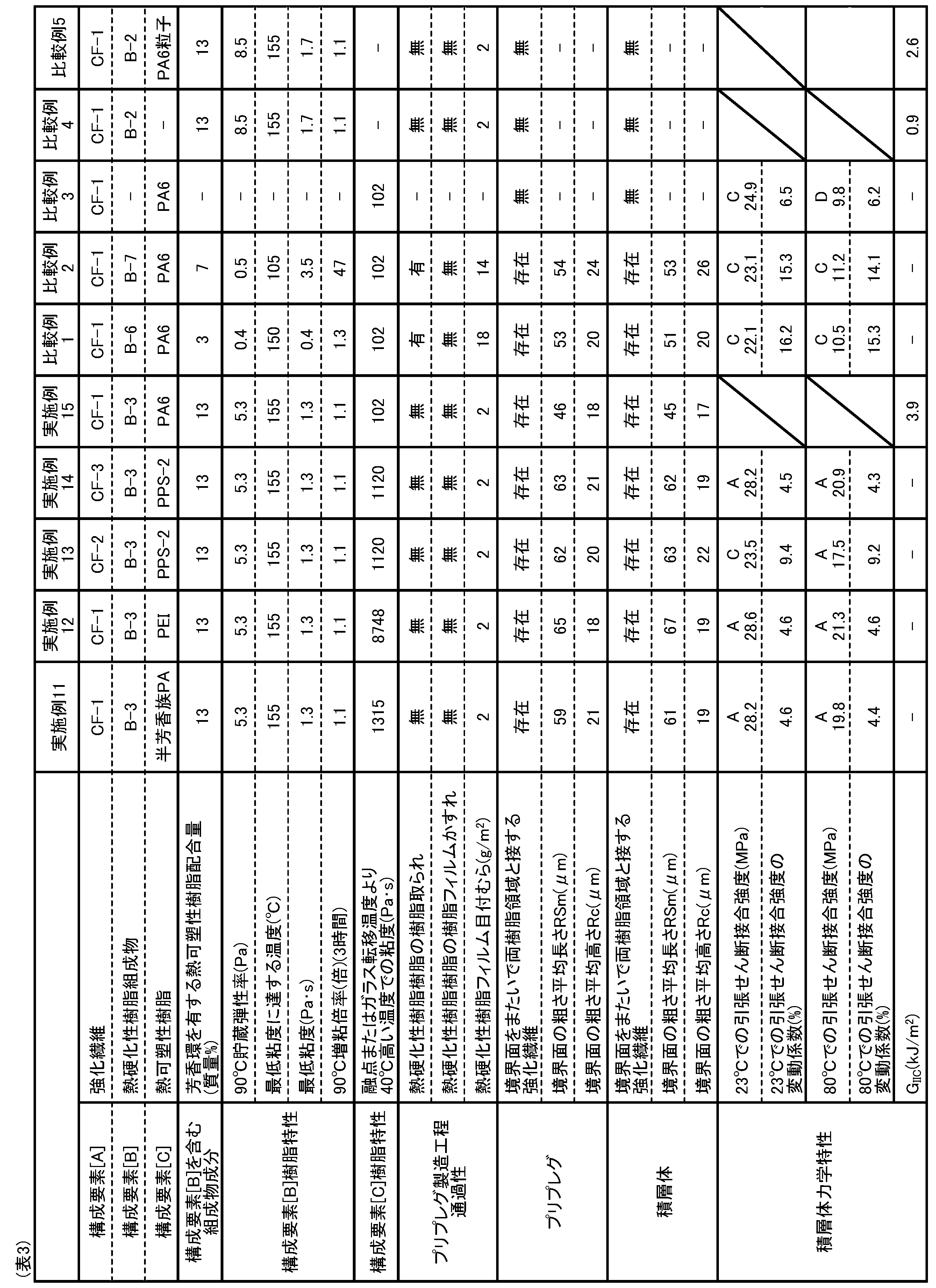
1:プリプレグまたは積層体
2:構成要素[A]
3:構成要素[C]および構成要素[B]または構成要素[D]
4:任意の繊維束の軸方向
5:観察断面
6:構成要素[A]
7:構成要素[C]を含む樹脂領域
8:構成要素[B]または構成要素[D]を含む樹脂領域
9:観察画像
10:境界面
11:基準線
12:垂基線
13:断面曲線 1: Prepreg or laminate 2: Component [A]
3: Component [C] and component [B] or component [D]
4: Axial direction of any fiber bundle 5: Observation cross section 6: Component [A]
7: Resin region containing component [C] 8: Resin region containing component [B] or component [D] 9: Observation image 10: Boundary surface 11: Reference line 12: Vertical baseline 13: Cross-sectional curve
Claims (15)
- 次の構成要素[A]、[B]および[C]を含むプリプレグであって、[B]は、芳香環を有する熱可塑性樹脂を10質量%以上含み、プリプレグの一方の表面に[B]を含む樹脂領域が、他方の表面に[C]を含む樹脂領域が存在しており、[B]を含む樹脂領域と[C]を含む樹脂領域との境界面をまたいで両樹脂領域と接する[A]が存在するプリプレグ。
[A]強化繊維
[B]熱硬化性樹脂
[C]熱可塑性樹脂 A prepreg containing the following components [A], [B] and [C], wherein [B] contains 10% by mass or more of a thermoplastic resin having an aromatic ring, and [B] is formed on one surface of the prepreg. The resin region containing [C] is present on the other surface, and is in contact with both resin regions across the interface between the resin region containing [B] and the resin region containing [C]. A prepreg in which [A] exists.
[A] Reinforcing fiber [B] Thermosetting resin [C] Thermoplastic resin - 前記プリプレグの平面視において、前記両樹脂領域と接する任意の[A]の繊維方向に対し45度異なる角度の方向から、前記[A]を含むプリプレグ平面に垂直な断面を得た場合に、前記断面における、両樹脂領域の密着する境界面が形成する断面曲線の、JIS B0601(2001)で定義される粗さ平均長さRSmが100μm以下であり、粗さ平均高さRcが3.5μm以上である、請求項1に記載のプリプレグ。 When a cross section perpendicular to the prepreg plane including the [A] is obtained from a direction at an angle 45 degrees different from the fiber direction of any [A] in contact with both resin regions in a plan view of the prepreg. In the cross section, the roughness average length RSm defined by JIS B0601 (2001) of the cross-sectional curve formed by the interface between the two resin regions in close contact is 100 μm or less, and the roughness average height Rc is 3.5 μm or more. The prepreg according to claim 1.
- 前記[B]を含む樹脂領域と前記[C]を含む樹脂領域とがそれぞれ層状をなして隣接することにより前記境界面を形成している、請求項1または2に記載のプリプレグ。 The prepreg according to claim 1 or 2, wherein the resin region containing [B] and the resin region containing [C] form a layer and are adjacent to each other to form the boundary surface.
- [B]は、レオメータによる1.5℃/minでの昇温過程において、90℃における貯蔵弾性率が1.0~100Paであり、最低粘度が0.5Pa・s以上であり、かつ前記最低粘度に到達する温度が120℃以上の領域にある、請求項1から3のいずれか1つに記載のプリプレグ。 [B] has a storage elastic modulus at 90 ° C. of 1.0 to 100 Pa, a minimum viscosity of 0.5 Pa · s or more, and the minimum temperature in the process of raising the temperature at 1.5 ° C./min by a rheometer. The prepreg according to any one of claims 1 to 3, wherein the temperature at which the viscosity is reached is in the region of 120 ° C. or higher.
- 次の構成要素[A]、[C]および[D]を含む層が含まれる積層体であって、[D]は、芳香環を有する熱可塑性樹脂を10質量%以上含み、[C]を含む樹脂領域と[D]を含む樹脂領域との境界面をまたいで両樹脂領域と接する[A]が存在する積層体。
[A]強化繊維
[C]熱可塑性樹脂
[D]熱硬化性樹脂硬化物 A laminate containing layers containing the following components [A], [C] and [D], wherein [D] contains 10% by mass or more of a thermoplastic resin having an aromatic ring, and contains [C]. A laminate in which [A] exists in contact with both resin regions across the interface between the resin region containing [D] and the resin region containing [D].
[A] Reinforcing fiber [C] Thermoplastic resin [D] Thermosetting resin cured product - 前記積層体の平面視において、前記両樹脂領域と接する任意の[A]の繊維方向に対し45度異なる角度の方向から、前記[A]を含む積層体の平面に垂直な断面を得た場合に、前記断面における、両樹脂領域の密着する境界面が形成する断面曲線の、JIS B0601(2001)で定義される粗さ平均長さRSmが100μm以下であり、粗さ平均高さRcが3.5μm以上である、請求項5に記載の積層体。 When a cross section perpendicular to the plane of the laminate containing [A] is obtained from a direction at an angle 45 degrees different from the fiber direction of any [A] in contact with both resin regions in a plan view of the laminate. In addition, the average roughness length RSm defined by JIS B0601 (2001) of the cross-sectional curve formed by the interface where the two resin regions are in close contact with each other in the cross section is 100 μm or less, and the average roughness height Rc is 3. The laminate according to claim 5, which is .5 μm or more.
- 前記[C]を含む樹脂領域と前記[D]を含む樹脂領域がそれぞれ層状をなして隣接することにより前記境界面を形成している、請求項5または6に記載の積層体。 The laminate according to claim 5 or 6, wherein the resin region containing [C] and the resin region containing [D] form a layer and are adjacent to each other to form the boundary surface.
- 表面に構成要素[C]を含む樹脂領域が存在する、請求項5から7のいずれか1つに記載の積層体。 The laminate according to any one of claims 5 to 7, wherein a resin region containing a component [C] is present on the surface.
- [D]が、硬化前の未硬化の状態にて、レオメータによる1.5℃/minでの昇温過程において、90℃における貯蔵弾性率が1.0~100Paであり、最低粘度が0.5Pa・s以上であり、かつ前記粘度に到達する温度が120℃以上の領域にある、請求項5から8のいずれか1つに記載の積層体。 In the uncured state before curing, [D] has a storage elastic modulus at 90 ° C. of 1.0 to 100 Pa and a minimum viscosity of 0. The laminate according to any one of claims 5 to 8, which is in the region of 5 Pa · s or more and the temperature at which the viscosity is reached is 120 ° C. or more.
- 以下の[1]および[2]の少なくとも一方を満たす、請求項1から4のいずれか1つに記載のプリプレグ、または、請求項5から9のいずれか1つに記載の積層体。
[1]前記芳香環を有する熱可塑性樹脂は、ポリエーテルスルホンまたはポリエーテルイミドである。
[2]前記芳香環を有する熱可塑性樹脂の重量平均分子量が、10,000g/mol以上40,000g/mol以下である。 The prepreg according to any one of claims 1 to 4, or the laminate according to any one of claims 5 to 9, which satisfies at least one of the following [1] and [2].
[1] The thermoplastic resin having the aromatic ring is a polyether sulfone or a polyetherimide.
[2] The weight average molecular weight of the thermoplastic resin having an aromatic ring is 10,000 g / mol or more and 40,000 g / mol or less. - 前記芳香環を有する熱可塑性樹脂の含有量が13質量%以上である、請求項1から4のいずれか1つに記載のプリプレグ、または、請求項5から10のいずれか1つに記載の積層体。 The prepreg according to any one of claims 1 to 4, or the laminate according to any one of claims 5 to 10, wherein the content of the thermoplastic resin having an aromatic ring is 13% by mass or more. body.
- [C]は、以下の[3]および[4]の少なくとも一方を満たす、請求項1から4のいずれか1つに記載のプリプレグ、または、請求項5から11のいずれか1つに記載の積層体。
[3]ポリアミド、ポリアリーレンエーテルケトン、ポリフェニレンスルフィド、ポリエーテルスルホンまたはポリエーテルイミドから選ばれる1種または2種以上である。
[4]結晶性熱可塑性樹脂の場合、融点より40℃高い温度での粘度、非晶性熱可塑性樹脂の場合、ガラス転移温度より40℃高い温度での粘度のそれぞれが1,000Pa・s以上100,000Pa・s以下である。 [C] is the prepreg according to any one of claims 1 to 4, or any one of claims 5 to 11, which satisfies at least one of the following [3] and [4]. Laminated body.
[3] One or more selected from polyamide, polyarylene ether ketone, polyphenylene sulfide, polyether sulfone or polyetherimide.
[4] In the case of crystalline thermoplastic resin, the viscosity at a temperature 40 ° C. higher than the melting point, and in the case of amorphous thermoplastic resin, the viscosity at a temperature 40 ° C. higher than the glass transition temperature is 1,000 Pa · s or more. It is 100,000 Pa · s or less. - [A]として、ウィルヘルミー法によって測定される表面自由エネルギーが10~50mJ/m2の強化繊維を用いる、請求項1から4のいずれか1つに記載のプリプレグ、または、請求項5から12のいずれか1つに記載の積層体。 The prepreg according to any one of claims 1 to 4, or the prepreg according to claims 5 to 12, which uses a reinforcing fiber having a surface free energy of 10 to 50 mJ / m 2 measured by the Wilhelmy method as [A]. The laminate according to any one.
- 請求項1から4のいずれか1つに記載のプリプレグの硬化物が少なくとも一部の層を構成する積層体。 A laminate in which the cured product of the prepreg according to any one of claims 1 to 4 constitutes at least a part of the layer.
- 別の部材が[C]が存在する面に接合することにより請求項8に記載の積層体と一体化されてなる一体化成形品。 An integrally molded product that is integrated with the laminate according to claim 8 by joining another member to the surface where [C] exists.
Priority Applications (4)
| Application Number | Priority Date | Filing Date | Title |
|---|---|---|---|
| US17/783,103 US20230001651A1 (en) | 2019-12-11 | 2020-11-20 | Prepreg, laminate, and integrated product |
| EP20899227.1A EP4074765A4 (en) | 2019-12-11 | 2020-11-20 | Prepreg, laminate, and integrated molded article |
| JP2020567264A JPWO2021117461A1 (en) | 2019-12-11 | 2020-11-20 | |
| CN202080084864.XA CN114787252A (en) | 2019-12-11 | 2020-11-20 | Prepreg, laminate, and integrated molded article |
Applications Claiming Priority (2)
| Application Number | Priority Date | Filing Date | Title |
|---|---|---|---|
| JP2019223484 | 2019-12-11 | ||
| JP2019-223484 | 2019-12-11 |
Publications (1)
| Publication Number | Publication Date |
|---|---|
| WO2021117461A1 true WO2021117461A1 (en) | 2021-06-17 |
Family
ID=76329799
Family Applications (1)
| Application Number | Title | Priority Date | Filing Date |
|---|---|---|---|
| PCT/JP2020/043325 WO2021117461A1 (en) | 2019-12-11 | 2020-11-20 | Prepreg, laminate, and integrated molded article |
Country Status (6)
| Country | Link |
|---|---|
| US (1) | US20230001651A1 (en) |
| EP (1) | EP4074765A4 (en) |
| JP (1) | JPWO2021117461A1 (en) |
| CN (1) | CN114787252A (en) |
| TW (1) | TW202130720A (en) |
| WO (1) | WO2021117461A1 (en) |
Families Citing this family (1)
| Publication number | Priority date | Publication date | Assignee | Title |
|---|---|---|---|---|
| TWI815650B (en) * | 2022-09-08 | 2023-09-11 | 臺灣塑膠工業股份有限公司 | Resin matrix composition, prepreg, carbon fiber composite and method of forming resin matrix |
Citations (7)
| Publication number | Priority date | Publication date | Assignee | Title |
|---|---|---|---|---|
| JPH08259713A (en) | 1995-03-22 | 1996-10-08 | Toray Ind Inc | Prepreg and fiber-reinforced composite material |
| JPH10138354A (en) | 1996-11-08 | 1998-05-26 | Yamaha Corp | Carbon fiber reinforced resin molded product and its manufacture |
| JP2004269878A (en) * | 2003-02-21 | 2004-09-30 | Toray Ind Inc | Fiber-reinforced composite material, method for producing the same and integrally molded product |
| JP2013209626A (en) * | 2012-02-28 | 2013-10-10 | Sumitomo Bakelite Co Ltd | Prepreg and prepreg manufacturing method |
| JP2016097676A (en) * | 2014-11-25 | 2016-05-30 | ザ・ボーイング・カンパニーThe Boeing Company | Composite laminate including interlayers with through-plane regions fused to fiber beds |
| JP2018161801A (en) | 2017-03-27 | 2018-10-18 | 三菱ケミカル株式会社 | Adhesion structural member |
| WO2019098243A1 (en) * | 2017-11-14 | 2019-05-23 | 東レ株式会社 | Prepreg and fiber reinforced composite material |
Family Cites Families (6)
| Publication number | Priority date | Publication date | Assignee | Title |
|---|---|---|---|---|
| CN100421924C (en) * | 2002-12-27 | 2008-10-01 | 东丽株式会社 | Layered product, electromagnetic-shielding molded object, and processes for producing these |
| TWI304321B (en) * | 2002-12-27 | 2008-12-11 | Toray Industries | Layered products, electromagnetic wave shielding molded articles and method for production thereof |
| JP5912920B2 (en) * | 2012-06-29 | 2016-04-27 | Jxエネルギー株式会社 | Fiber reinforced composite material |
| WO2014017339A1 (en) * | 2012-07-25 | 2014-01-30 | 東レ株式会社 | Prepreg and carbon-fiber-reinforced composite material |
| JP5655976B1 (en) * | 2013-01-28 | 2015-01-21 | 東レ株式会社 | Prepreg, fiber reinforced composite material and thermoplastic resin particles |
| WO2018173716A1 (en) * | 2017-03-22 | 2018-09-27 | 東レ株式会社 | Epoxy resin composition, prepreg, and carbon fiber-reinforced composite material |
-
2020
- 2020-11-20 CN CN202080084864.XA patent/CN114787252A/en active Pending
- 2020-11-20 TW TW109140772A patent/TW202130720A/en unknown
- 2020-11-20 WO PCT/JP2020/043325 patent/WO2021117461A1/en unknown
- 2020-11-20 US US17/783,103 patent/US20230001651A1/en active Pending
- 2020-11-20 EP EP20899227.1A patent/EP4074765A4/en active Pending
- 2020-11-20 JP JP2020567264A patent/JPWO2021117461A1/ja active Pending
Patent Citations (7)
| Publication number | Priority date | Publication date | Assignee | Title |
|---|---|---|---|---|
| JPH08259713A (en) | 1995-03-22 | 1996-10-08 | Toray Ind Inc | Prepreg and fiber-reinforced composite material |
| JPH10138354A (en) | 1996-11-08 | 1998-05-26 | Yamaha Corp | Carbon fiber reinforced resin molded product and its manufacture |
| JP2004269878A (en) * | 2003-02-21 | 2004-09-30 | Toray Ind Inc | Fiber-reinforced composite material, method for producing the same and integrally molded product |
| JP2013209626A (en) * | 2012-02-28 | 2013-10-10 | Sumitomo Bakelite Co Ltd | Prepreg and prepreg manufacturing method |
| JP2016097676A (en) * | 2014-11-25 | 2016-05-30 | ザ・ボーイング・カンパニーThe Boeing Company | Composite laminate including interlayers with through-plane regions fused to fiber beds |
| JP2018161801A (en) | 2017-03-27 | 2018-10-18 | 三菱ケミカル株式会社 | Adhesion structural member |
| WO2019098243A1 (en) * | 2017-11-14 | 2019-05-23 | 東レ株式会社 | Prepreg and fiber reinforced composite material |
Non-Patent Citations (1)
| Title |
|---|
| See also references of EP4074765A4 |
Also Published As
| Publication number | Publication date |
|---|---|
| JPWO2021117461A1 (en) | 2021-06-17 |
| EP4074765A4 (en) | 2023-12-20 |
| EP4074765A1 (en) | 2022-10-19 |
| US20230001651A1 (en) | 2023-01-05 |
| TW202130720A (en) | 2021-08-16 |
| CN114787252A (en) | 2022-07-22 |
Similar Documents
| Publication | Publication Date | Title |
|---|---|---|
| JP7047923B2 (en) | Prepregs, laminates and moldings | |
| WO2020235487A1 (en) | Prepreg, laminate, and molded article | |
| EP3974466A1 (en) | Prepreg, laminate, and molded article | |
| WO2020235484A1 (en) | Prepreg, laminate, and molded article | |
| WO2021131382A1 (en) | Composite prepreg and fiber-reinforced resin molded product | |
| WO2021117461A1 (en) | Prepreg, laminate, and integrated molded article | |
| WO2020235486A1 (en) | Prepreg, multilayer body and molded article | |
| JP7088320B2 (en) | Prepregs, laminates and integrally molded products | |
| WO2021117460A1 (en) | Prepreg, laminate and integrated molded article | |
| JP7180790B2 (en) | Prepregs, fiber-reinforced resin moldings and integrated moldings | |
| WO2022107563A1 (en) | Fiber-reinforced resin, and integrally molded product | |
| JP7088433B1 (en) | Prepregs, moldings and integral moldings |
Legal Events
| Date | Code | Title | Description |
|---|---|---|---|
| ENP | Entry into the national phase |
Ref document number: 2020567264 Country of ref document: JP Kind code of ref document: A |
|
| 121 | Ep: the epo has been informed by wipo that ep was designated in this application |
Ref document number: 20899227 Country of ref document: EP Kind code of ref document: A1 |
|
| NENP | Non-entry into the national phase |
Ref country code: DE |
|
| ENP | Entry into the national phase |
Ref document number: 2020899227 Country of ref document: EP Effective date: 20220711 |