WO2021117404A1 - 駆動ユニットの動作方法及びコントローラー - Google Patents
駆動ユニットの動作方法及びコントローラー Download PDFInfo
- Publication number
- WO2021117404A1 WO2021117404A1 PCT/JP2020/041911 JP2020041911W WO2021117404A1 WO 2021117404 A1 WO2021117404 A1 WO 2021117404A1 JP 2020041911 W JP2020041911 W JP 2020041911W WO 2021117404 A1 WO2021117404 A1 WO 2021117404A1
- Authority
- WO
- WIPO (PCT)
- Prior art keywords
- pulse
- drive
- ois
- drive unit
- duty cycle
- Prior art date
- Legal status (The legal status is an assumption and is not a legal conclusion. Google has not performed a legal analysis and makes no representation as to the accuracy of the status listed.)
- Ceased
Links
Images












Classifications
-
- H—ELECTRICITY
- H02—GENERATION; CONVERSION OR DISTRIBUTION OF ELECTRIC POWER
- H02N—ELECTRIC MACHINES NOT OTHERWISE PROVIDED FOR
- H02N2/00—Electric machines in general using piezoelectric effect, electrostriction or magnetostriction
- H02N2/0005—Electric machines in general using piezoelectric effect, electrostriction or magnetostriction producing non-specific motion; Details common to machines covered by H02N2/02 - H02N2/16
- H02N2/0075—Electrical details, e.g. drive or control circuits or methods
-
- G—PHYSICS
- G02—OPTICS
- G02B—OPTICAL ELEMENTS, SYSTEMS OR APPARATUS
- G02B7/00—Mountings, adjusting means, or light-tight connections, for optical elements
- G02B7/02—Mountings, adjusting means, or light-tight connections, for optical elements for lenses
-
- G—PHYSICS
- G02—OPTICS
- G02B—OPTICAL ELEMENTS, SYSTEMS OR APPARATUS
- G02B7/00—Mountings, adjusting means, or light-tight connections, for optical elements
- G02B7/02—Mountings, adjusting means, or light-tight connections, for optical elements for lenses
- G02B7/04—Mountings, adjusting means, or light-tight connections, for optical elements for lenses with mechanism for focusing or varying magnification
- G02B7/08—Mountings, adjusting means, or light-tight connections, for optical elements for lenses with mechanism for focusing or varying magnification adapted to co-operate with a remote control mechanism
-
- G—PHYSICS
- G02—OPTICS
- G02B—OPTICAL ELEMENTS, SYSTEMS OR APPARATUS
- G02B27/00—Optical systems or apparatus not provided for by any of the groups G02B1/00 - G02B26/00, G02B30/00
- G02B27/64—Imaging systems using optical elements for stabilisation of the lateral and angular position of the image
- G02B27/646—Imaging systems using optical elements for stabilisation of the lateral and angular position of the image compensating for small deviations, e.g. due to vibration or shake
-
- G—PHYSICS
- G02—OPTICS
- G02B—OPTICAL ELEMENTS, SYSTEMS OR APPARATUS
- G02B7/00—Mountings, adjusting means, or light-tight connections, for optical elements
- G02B7/02—Mountings, adjusting means, or light-tight connections, for optical elements for lenses
- G02B7/04—Mountings, adjusting means, or light-tight connections, for optical elements for lenses with mechanism for focusing or varying magnification
-
- G—PHYSICS
- G03—PHOTOGRAPHY; CINEMATOGRAPHY; ANALOGOUS TECHNIQUES USING WAVES OTHER THAN OPTICAL WAVES; ELECTROGRAPHY; HOLOGRAPHY
- G03B—APPARATUS OR ARRANGEMENTS FOR TAKING PHOTOGRAPHS OR FOR PROJECTING OR VIEWING THEM; APPARATUS OR ARRANGEMENTS EMPLOYING ANALOGOUS TECHNIQUES USING WAVES OTHER THAN OPTICAL WAVES; ACCESSORIES THEREFOR
- G03B13/00—Viewfinders; Focusing aids for cameras; Means for focusing for cameras; Autofocus systems for cameras
- G03B13/32—Means for focusing
- G03B13/34—Power focusing
- G03B13/36—Autofocus systems
-
- G—PHYSICS
- G03—PHOTOGRAPHY; CINEMATOGRAPHY; ANALOGOUS TECHNIQUES USING WAVES OTHER THAN OPTICAL WAVES; ELECTROGRAPHY; HOLOGRAPHY
- G03B—APPARATUS OR ARRANGEMENTS FOR TAKING PHOTOGRAPHS OR FOR PROJECTING OR VIEWING THEM; APPARATUS OR ARRANGEMENTS EMPLOYING ANALOGOUS TECHNIQUES USING WAVES OTHER THAN OPTICAL WAVES; ACCESSORIES THEREFOR
- G03B3/00—Focusing arrangements of general interest for cameras, projectors or printers
- G03B3/10—Power-operated focusing
-
- G—PHYSICS
- G03—PHOTOGRAPHY; CINEMATOGRAPHY; ANALOGOUS TECHNIQUES USING WAVES OTHER THAN OPTICAL WAVES; ELECTROGRAPHY; HOLOGRAPHY
- G03B—APPARATUS OR ARRANGEMENTS FOR TAKING PHOTOGRAPHS OR FOR PROJECTING OR VIEWING THEM; APPARATUS OR ARRANGEMENTS EMPLOYING ANALOGOUS TECHNIQUES USING WAVES OTHER THAN OPTICAL WAVES; ACCESSORIES THEREFOR
- G03B30/00—Camera modules comprising integrated lens units and imaging units, specially adapted for being embedded in other devices, e.g. mobile phones or vehicles
-
- G—PHYSICS
- G03—PHOTOGRAPHY; CINEMATOGRAPHY; ANALOGOUS TECHNIQUES USING WAVES OTHER THAN OPTICAL WAVES; ELECTROGRAPHY; HOLOGRAPHY
- G03B—APPARATUS OR ARRANGEMENTS FOR TAKING PHOTOGRAPHS OR FOR PROJECTING OR VIEWING THEM; APPARATUS OR ARRANGEMENTS EMPLOYING ANALOGOUS TECHNIQUES USING WAVES OTHER THAN OPTICAL WAVES; ACCESSORIES THEREFOR
- G03B5/00—Adjustment of optical system relative to image or object surface other than for focusing
-
- H—ELECTRICITY
- H02—GENERATION; CONVERSION OR DISTRIBUTION OF ELECTRIC POWER
- H02N—ELECTRIC MACHINES NOT OTHERWISE PROVIDED FOR
- H02N2/00—Electric machines in general using piezoelectric effect, electrostriction or magnetostriction
- H02N2/0005—Electric machines in general using piezoelectric effect, electrostriction or magnetostriction producing non-specific motion; Details common to machines covered by H02N2/02 - H02N2/16
- H02N2/0075—Electrical details, e.g. drive or control circuits or methods
- H02N2/008—Means for controlling vibration frequency or phase, e.g. for resonance tracking
-
- H—ELECTRICITY
- H02—GENERATION; CONVERSION OR DISTRIBUTION OF ELECTRIC POWER
- H02N—ELECTRIC MACHINES NOT OTHERWISE PROVIDED FOR
- H02N2/00—Electric machines in general using piezoelectric effect, electrostriction or magnetostriction
- H02N2/02—Electric machines in general using piezoelectric effect, electrostriction or magnetostriction producing linear motion, e.g. actuators; Linear positioners ; Linear motors
- H02N2/06—Drive circuits; Control arrangements or methods
- H02N2/065—Large signal circuits, e.g. final stages
- H02N2/067—Large signal circuits, e.g. final stages generating drive pulses
-
- H—ELECTRICITY
- H02—GENERATION; CONVERSION OR DISTRIBUTION OF ELECTRIC POWER
- H02N—ELECTRIC MACHINES NOT OTHERWISE PROVIDED FOR
- H02N2/00—Electric machines in general using piezoelectric effect, electrostriction or magnetostriction
- H02N2/10—Electric machines in general using piezoelectric effect, electrostriction or magnetostriction producing rotary motion, e.g. rotary motors
- H02N2/14—Drive circuits; Control arrangements or methods
-
- H—ELECTRICITY
- H02—GENERATION; CONVERSION OR DISTRIBUTION OF ELECTRIC POWER
- H02N—ELECTRIC MACHINES NOT OTHERWISE PROVIDED FOR
- H02N2/00—Electric machines in general using piezoelectric effect, electrostriction or magnetostriction
- H02N2/10—Electric machines in general using piezoelectric effect, electrostriction or magnetostriction producing rotary motion, e.g. rotary motors
- H02N2/14—Drive circuits; Control arrangements or methods
- H02N2/145—Large signal circuits, e.g. final stages
-
- H—ELECTRICITY
- H04—ELECTRIC COMMUNICATION TECHNIQUE
- H04N—PICTORIAL COMMUNICATION, e.g. TELEVISION
- H04N23/00—Cameras or camera modules comprising electronic image sensors; Control thereof
- H04N23/50—Constructional details
- H04N23/55—Optical parts specially adapted for electronic image sensors; Mounting thereof
-
- H—ELECTRICITY
- H04—ELECTRIC COMMUNICATION TECHNIQUE
- H04N—PICTORIAL COMMUNICATION, e.g. TELEVISION
- H04N23/00—Cameras or camera modules comprising electronic image sensors; Control thereof
- H04N23/60—Control of cameras or camera modules
-
- H—ELECTRICITY
- H04—ELECTRIC COMMUNICATION TECHNIQUE
- H04N—PICTORIAL COMMUNICATION, e.g. TELEVISION
- H04N23/00—Cameras or camera modules comprising electronic image sensors; Control thereof
- H04N23/60—Control of cameras or camera modules
- H04N23/68—Control of cameras or camera modules for stable pick-up of the scene, e.g. compensating for camera body vibrations
- H04N23/682—Vibration or motion blur correction
- H04N23/685—Vibration or motion blur correction performed by mechanical compensation
- H04N23/687—Vibration or motion blur correction performed by mechanical compensation by shifting the lens or sensor position
-
- G—PHYSICS
- G02—OPTICS
- G02B—OPTICAL ELEMENTS, SYSTEMS OR APPARATUS
- G02B7/00—Mountings, adjusting means, or light-tight connections, for optical elements
- G02B7/02—Mountings, adjusting means, or light-tight connections, for optical elements for lenses
- G02B7/04—Mountings, adjusting means, or light-tight connections, for optical elements for lenses with mechanism for focusing or varying magnification
- G02B7/09—Mountings, adjusting means, or light-tight connections, for optical elements for lenses with mechanism for focusing or varying magnification adapted for automatic focusing or varying magnification
-
- G—PHYSICS
- G03—PHOTOGRAPHY; CINEMATOGRAPHY; ANALOGOUS TECHNIQUES USING WAVES OTHER THAN OPTICAL WAVES; ELECTROGRAPHY; HOLOGRAPHY
- G03B—APPARATUS OR ARRANGEMENTS FOR TAKING PHOTOGRAPHS OR FOR PROJECTING OR VIEWING THEM; APPARATUS OR ARRANGEMENTS EMPLOYING ANALOGOUS TECHNIQUES USING WAVES OTHER THAN OPTICAL WAVES; ACCESSORIES THEREFOR
- G03B2205/00—Adjustment of optical system relative to image or object surface other than for focusing
- G03B2205/0007—Movement of one or more optical elements for control of motion blur
-
- G—PHYSICS
- G03—PHOTOGRAPHY; CINEMATOGRAPHY; ANALOGOUS TECHNIQUES USING WAVES OTHER THAN OPTICAL WAVES; ELECTROGRAPHY; HOLOGRAPHY
- G03B—APPARATUS OR ARRANGEMENTS FOR TAKING PHOTOGRAPHS OR FOR PROJECTING OR VIEWING THEM; APPARATUS OR ARRANGEMENTS EMPLOYING ANALOGOUS TECHNIQUES USING WAVES OTHER THAN OPTICAL WAVES; ACCESSORIES THEREFOR
- G03B2205/00—Adjustment of optical system relative to image or object surface other than for focusing
- G03B2205/0046—Movement of one or more optical elements for zooming
-
- G—PHYSICS
- G03—PHOTOGRAPHY; CINEMATOGRAPHY; ANALOGOUS TECHNIQUES USING WAVES OTHER THAN OPTICAL WAVES; ELECTROGRAPHY; HOLOGRAPHY
- G03B—APPARATUS OR ARRANGEMENTS FOR TAKING PHOTOGRAPHS OR FOR PROJECTING OR VIEWING THEM; APPARATUS OR ARRANGEMENTS EMPLOYING ANALOGOUS TECHNIQUES USING WAVES OTHER THAN OPTICAL WAVES; ACCESSORIES THEREFOR
- G03B2205/00—Adjustment of optical system relative to image or object surface other than for focusing
- G03B2205/0053—Driving means for the movement of one or more optical element
- G03B2205/0061—Driving means for the movement of one or more optical element using piezoelectric actuators
-
- H—ELECTRICITY
- H02—GENERATION; CONVERSION OR DISTRIBUTION OF ELECTRIC POWER
- H02N—ELECTRIC MACHINES NOT OTHERWISE PROVIDED FOR
- H02N2/00—Electric machines in general using piezoelectric effect, electrostriction or magnetostriction
- H02N2/0005—Electric machines in general using piezoelectric effect, electrostriction or magnetostriction producing non-specific motion; Details common to machines covered by H02N2/02 - H02N2/16
- H02N2/001—Driving devices, e.g. vibrators
-
- H—ELECTRICITY
- H02—GENERATION; CONVERSION OR DISTRIBUTION OF ELECTRIC POWER
- H02N—ELECTRIC MACHINES NOT OTHERWISE PROVIDED FOR
- H02N2/00—Electric machines in general using piezoelectric effect, electrostriction or magnetostriction
- H02N2/02—Electric machines in general using piezoelectric effect, electrostriction or magnetostriction producing linear motion, e.g. actuators; Linear positioners ; Linear motors
- H02N2/026—Electric machines in general using piezoelectric effect, electrostriction or magnetostriction producing linear motion, e.g. actuators; Linear positioners ; Linear motors by pressing one or more vibrators against the driven body
-
- H—ELECTRICITY
- H02—GENERATION; CONVERSION OR DISTRIBUTION OF ELECTRIC POWER
- H02N—ELECTRIC MACHINES NOT OTHERWISE PROVIDED FOR
- H02N2/00—Electric machines in general using piezoelectric effect, electrostriction or magnetostriction
- H02N2/10—Electric machines in general using piezoelectric effect, electrostriction or magnetostriction producing rotary motion, e.g. rotary motors
- H02N2/103—Electric machines in general using piezoelectric effect, electrostriction or magnetostriction producing rotary motion, e.g. rotary motors by pressing one or more vibrators against the rotor
Definitions
- the present invention relates to the field of a small drive device such as a piezoelectric drive device. More specifically, the present invention relates to a drive unit operating method and a controller according to the corresponding independent claim preamble.
- Such a drive device comprises one, two, or more arms made to vibrate and drives the passive element by vibrating motion at the end of the arm.
- the frequency of the excitation means driving the vibrating motion is selected so that the arm creates a vibrating mode in which the passive element is moved in a first direction or the opposite second direction. Further improvements in the drive are needed, taking into account the non-linear characteristics inherent in the design of the drive, especially in order to control the position of the passive element relative to the active element.
- An object of the present invention is to provide a drive unit operation method that enables position control of the above-mentioned type of drive unit and a controller that controls the operation of the drive unit.
- the operation method of the drive unit according to the present invention is as follows. It is a method of operating a drive unit that drives a passive element with respect to an active element.
- the active element comprises a resonator and at least one excitation means for exciting the vibration of the resonator.
- the resonator comprises at least one arm extending from the connection of the resonator.
- the at least one arm includes a contact portion at the outer end of the arm.
- the contact portion is movable by the vibrating motion of the at least one arm.
- the passive element is driven by the vibrating motion and is arranged to move relative to the active element.
- the passive element has a first contact area and is arranged such that the first contact area is in contact with the first contact portion.
- the active element and the passive element are arranged so that at least the first contact portion is pushed toward the first contact region by a prestress force when the active element is not excited.
- the excitation means is driven by a drive signal which is a periodic signal including a drive pulse repeated at an excitation frequency, and the drive pulse is repeatedly omitted, whereby the relationship between the pulse block on-time Ton and the pulse block period Tb Ton / A step of generating a periodically repeated pulse block, in which Tb is a pulse block duty cycle, Including a step of modifying the drive signal according to the position error signal.
- the shape of the drive pulse is modified so as to have the shape of the first drive pulse, or the excitation frequency is modified by the first excitation frequency detuning value, and the excitation frequency is modified.
- the pulse block duty cycle is set to the first pulse block duty cycle value, and the pulse block duty cycle is set to the first pulse block duty cycle value.
- the shape of the drive pulse is modified so as to have the shape of the second drive pulse, or the excitation frequency is modified by the second excitation frequency detuning value.
- the pulse block duty cycle is set to the second pulse block duty cycle value.
- the controller according to the present invention is A controller configured to perform the above drive unit operating methods.
- the position of the drive unit is determined by connecting to and supplying power to the excitation means of the drive unit and reading a signal from the sensor.
- FIG. 1A and 1B are diagrams showing a smartphone equipped with a camera module according to an embodiment of the present invention.
- FIG. 2 is an external perspective view of the camera module.
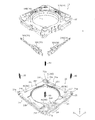
- 3A and 3B are external perspective views of the lens driving device according to the first embodiment.
- FIG. 4 is an exploded perspective view of the lens driving device according to the first embodiment.
- FIG. 5 is an exploded perspective view of the lens driving device according to the first embodiment.
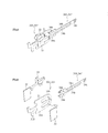
- 6A and 6B are perspective views of the OIS drive unit.
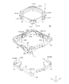
- FIG. 7 is an exploded perspective view of the OIS movable portion according to the first embodiment.
- FIG. 8 is an exploded perspective view of the OIS movable portion according to the first embodiment.
- FIG. 9 is an exploded perspective view of the OIS movable portion according to the first embodiment.
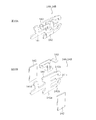
- FIG. 10A and 10B are perspective views of the AF drive unit according to the first embodiment.
- 11A and 11B are views showing a state in which the first stage, the AF drive unit, and the AF support unit according to the first embodiment are assembled.
- 12A and 12B are external perspective views of the lens driving device according to the second embodiment.
- FIG. 13 is an exploded perspective view of the OIS movable portion according to the second embodiment.
- FIG. 14 is an exploded perspective view of the OIS movable portion according to the second embodiment.
- FIG. 15 is an exploded perspective view of the OIS movable portion according to the second embodiment.
- 16A and 16B are views showing a state in which the first stage, the AF drive unit, and the AF support unit according to the second embodiment are assembled.
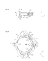
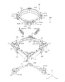
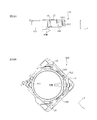
- FIG. 17 is a diagram of a drive unit for vibration drive.
- 18A and 18B are diagrams of a drive unit for driving vibration.
- FIG. 19 is a diagram of a drive unit for vibration drive.
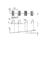
- FIG. 20 is a diagram of a drive signal when the shape of the drive pulse is adjusted and the vibration amplitude generated as a result.
- FIG. 21 is a diagram of a drive signal and the resulting vibration amplitude when the presence of the drive pulse is adjusted.
- FIG. 22 is a diagram showing the dependency relationship of the drive speed v with respect to the pulse duty cycle dp.
- FIG. 23 is a diagram showing the dependency relationship of the drive speed v with respect to the excitation frequency f.
- FIG. 24 is a flow chart showing a driving method of the driving unit.
- 25A and 25B are diagrams showing an automobile as a camera-mounted device for mounting an in-vehicle camera module.
- FIG. 1A and 1B are diagrams showing a smartphone M (an example of a camera-mounted device) equipped with a camera module A according to an embodiment of the present invention.
- FIG. 1A is a front view of the smartphone M
- FIG. 1B is a rear view of the smartphone M.
- the smartphone M has a dual camera including two rear cameras OC1 and OC2.
- the camera module A is applied to the rear cameras OC1 and OC2.
- the camera module A has an AF function and an OIS function, automatically adjusts the focus when shooting a subject, and optically corrects the shake (vibration) that occurs during shooting to shoot an image without image blur. be able to.
- FIG. 2 is an external perspective view of the camera module A.
- 3A and 3B are external perspective views of the lens driving device 1 according to the first embodiment.
- FIG. 3B shows a state in which FIG. 3A is rotated by 180 ° around the Z axis.
- the present embodiment will be described using a Cartesian coordinate system (X, Y, Z). Also in the figure described later, it is shown by a common Cartesian coordinate system (X, Y, Z).
- the X direction is the vertical direction (or the horizontal direction)
- the Y direction is the horizontal direction (or the vertical direction)
- the Z direction is the front-back direction. It will be installed. That is, the Z direction is the optical axis direction, the upper side (+ Z side) in the figure is the optical axis direction light receiving side, and the lower side ( ⁇ Z side) is the optical axis direction imaging side.
- the X and Y directions orthogonal to the Z axis are referred to as "optical axis orthogonal directions”
- the XY planes are referred to as "optical axis orthogonal planes”.
- the camera module A includes a lens driving device 1 that realizes an AF function and an OIS function, a lens unit 2 in which a lens is housed in a cylindrical lens barrel, and a lens unit 2. It is provided with an imaging unit (not shown) that captures a subject image imaged by the lens, a cover 3 that covers the entire image, and the like.
- the cover 3 is a covered square cylinder having a rectangular shape in a plan view when viewed from the optical axis direction.
- the cover 3 has a square shape in a plan view.
- the cover 3 has a substantially circular opening 3a on the upper surface.
- the lens portion 2 is configured to face the outside from the opening 3a and project toward the light receiving side from the opening surface of the cover 3 as it moves in the optical axis direction.
- the cover 3 is fixed to the base 21 (see FIG. 4) of the OIS fixing portion 20 of the lens driving device 1, for example, by adhesion.
- the imaging unit (not shown) is arranged on the optical axis direction imaging side of the lens driving device 1.
- the image pickup unit (not shown) has, for example, an image sensor substrate and an image pickup element mounted on the image sensor substrate.
- the image sensor is composed of, for example, a CCD (charge-coupled device) type image sensor, a CMOS (complementary metal oxide semiconductor) type image sensor, and the like.
- the image sensor captures a subject image imaged by the lens unit 2.
- the lens driving device 1 is mounted on an image sensor substrate (not shown) and is mechanically and electrically connected.
- the control unit that controls the drive of the lens driving device 1 may be provided on the image sensor substrate, or may be provided on the camera-mounted device (smartphone M in the present embodiment) on which the camera module A is mounted. ..
- FIGS. 4 and 5 are exploded perspective views of the lens driving device 1 according to the first embodiment.
- FIG. 5 shows a state in which FIG. 4 is rotated by 180 ° around the Z axis.
- the lens driving device 1 includes an OIS movable portion 10 (second movable portion), an OIS fixing portion 20 (second fixed portion), and an OIS driving unit 30 (XY).
- a directional drive unit) and an OIS support unit 40 (second support unit) are provided.
- the portion of the wiring 24 embedded in the base 21 is shown by a dotted line.
- the OIS movable portion 10 is a portion that swings in the plane orthogonal to the optical axis during image stabilization.
- the OIS movable portion 10 includes an AF unit, a second stage 13, and a ball 42.
- the AF unit has an AF movable part 11 (first movable part), a first stage 12 (first fixed part), an AF drive part 14 (Z direction drive part), and an AF support part 15 (first support part) ( 7-9).
- the OIS fixing portion 20 is a portion to which the OIS movable portion 10 is connected via the OIS supporting portion 40.
- the OIS fixing portion 20 includes a base 21.
- the OIS movable portion 10 is arranged at a distance from the OIS fixing portion 20 in the optical axis direction, and is connected to the OIS fixing portion 20 via the OIS support portion 40. Further, the OIS movable portion 10 and the OIS fixing portion 20 are urged in a direction approaching each other by the OIS urging members 50 provided at the four corners.
- the entire OIS movable portion 10 including the AF unit moves as a movable body.
- the AF unit moves as a movable body. That is, with respect to the movement in the X direction, the second stage 13 constitutes the OIS fixing portion 20 together with the base 21, and the ball 42 functions as the OIS supporting portion 40.
- the base 21 has a rectangular shape in a plan view, which is formed of, for example, a polyarylate (PAR), a PAR alloy in which a plurality of resin materials including PAR are mixed (for example, PAR / PC), or a molding material made of a liquid crystal polymer. It is a member and has a circular opening 21a in the center.
- the base 21 has a first base portion 21b forming the main surface of the base 21 and a second base portion 21c formed at one corner of the four corners, and between the first base portion 21b and the second base portion 21c. It is formed in a dent.
- the sensor substrate 22 is arranged in this recess, and a flush base surface is formed by the first base portion 21b, the second base portion 21c, and the sensor substrate 22.
- the base 21 has an OIS motor fixing portion 21d in which a second OIS drive portion 30Y is arranged at a portion located diagonally of the second base portion 21c.
- the OIS motor fixing portion 21d is formed so as to project from the first base portion 21b toward the light receiving side in the optical axis direction, and has a shape capable of holding the second OIS drive portion 30Y.
- the terminal fitting 23 and the wiring 24 are arranged on the base 21 by, for example, insert molding.
- the wiring 24 includes a power supply line to the AF drive unit 14 and the OIS drive unit 30.
- the wiring 24 is exposed from the openings 21g formed at the four corners of the base 21 and is electrically connected to the OIS urging member 50. Power is supplied to the AF drive unit 14 and the first OIS drive unit 30X via the OIS urging member 50.
- the terminal fitting 23 is electrically connected to a wiring (not shown) formed on the sensor substrate 22.
- the base 21 has ball accommodating portions 21e and 21f for accommodating the balls 41.
- the ball accommodating portion 21e formed in the second base portion 21c is formed by being recessed in a circular shape, and the three ball accommodating portions 21f formed in the first base portion 21b are recessed in a rectangular shape extending in the Y direction. Is formed of.
- the side surface of the ball accommodating portion 21f is formed in a tapered shape so that the groove width becomes narrower toward the bottom surface side, for example.
- the sensor board 22 has wiring (not shown) including a power supply line and a signal line for the magnetic sensors 25X and 25Y.
- Magnetic sensors 25X and 25Y are mounted on the sensor board 22.
- the magnetic sensors 25X and 25Y are composed of, for example, a Hall element or a TMR (Tunnel Magneto Resistance) sensor, and are electrically connected to the terminal fitting 23 via wiring (not shown) formed on the sensor substrate 22. ..
- magnets 16X and 16Y are arranged at positions facing the magnetic sensors 25X and 25Y.
- the position detection unit including the magnetic sensors 25X and 25Y and the magnets 16X and 16Y detects the positions of the OIS movable unit 10 in the X and Y directions. Instead of the magnets 16X and 16Y and the magnetic sensors 25X and 25Y, the positions of the OIS movable portion 10 in the X and Y directions may be detected by an optical sensor such as a photoreflector.
- the OIS urging member 50 is composed of, for example, a tension coil spring, and connects the OIS movable portion 10 and the OIS fixing portion 20.
- one end of the OIS urging member 50 is connected to the wiring 24 of the base 21, and the other end is connected to the wiring 17 of the first stage 12.
- the OIS urging member 50 receives a tensile load when the OIS movable portion 10 and the OIS fixing portion 20 are connected, and acts so that the OIS movable portion 10 and the OIS fixing portion 20 approach each other.
- the OIS movable portion 10 is oscillatingly held in the XY plane in a state of being urged in the optical axis direction (a state of being pressed against the base 21) by the OIS urging member 50.
- the OIS urging member 50 functions as a power supply line to the AF drive unit 14 and the first OIS drive unit 30X.
- the OIS support portion 40 supports the OIS movable portion 10 with respect to the OIS fixing portion 20 in a state of being separated from each other in the optical axis direction.
- the OIS support portion 40 includes four balls 41 interposed between the OIS movable portion 10 (first stage 12 and the second stage 13) and the base 21.
- One ball 41 arranged in the ball accommodating portion 21e of the base 21 is interposed between the base 21 and the first stage 12, and the three balls 41 arranged in the ball accommodating portion 21f are the base 21 and the first stage 12. It intervenes between the two stages 13.
- the OIS support portion 40 includes three balls 42 interposed between the first stage 12 and the second stage 13 in the OIS movable portion 10 (see FIG. 7 and the like).
- the OIS movable portion 10 can be swung accurately in the XY plane. It has become.
- the number of balls 41, 42 constituting the OIS support portion 40 can be changed as appropriate.
- the OIS drive unit 30 is an actuator that moves the OIS movable unit 10 in the X direction and the Y direction.
- the OIS drive unit 30 includes a first OIS drive unit 30X (first XY direction drive unit) that moves the OIS movable unit 10 (AF unit only) in the X direction, and the entire OIS movable unit 10. It is composed of a second OIS drive unit 30Y (second XY direction drive unit) that moves in the Y direction.
- the first and second OIS drive units 30X and 30Y are composed of ultrasonic motors.
- the first OIS drive unit 30X is fixed to the OIS motor fixing unit 12f of the first stage 12 so as to extend along the X direction.
- the second OIS drive unit 30Y is fixed to the OIS motor fixing unit 21d of the base 21 so as to extend along the Y direction. That is, the first OIS drive unit 30X and the second OIS drive unit 30Y are arranged along the sides orthogonal to each other.
- FIGS. 6A and 6B The configuration of the OIS drive unit 30 is shown in FIGS. 6A and 6B.
- FIG. 6A shows a state in which each member of the OIS drive unit 30 is assembled
- FIG. 6B shows a state in which each member of the OIS drive unit 30 is disassembled.
- FIGS. 6A and 6B show the second OIS drive unit 30Y
- the main configuration of the first OIS drive unit 30X specifically, the configuration excluding the shapes of the OIS resonance unit 31 and the electrode 33 is Since it is the same, it is treated as a diagram showing the OIS drive unit 30.
- the OIS drive unit 30 has an OIS resonance unit 31, an OIS piezoelectric element 32, and an OIS electrode 33.
- the driving force of the OIS drive unit 30 is transmitted to the second stage 13 via the OIS power transmission unit 34.
- the first OIS drive unit 30X is connected to the first OIS power transmission unit 34X
- the second OIS drive unit 30Y is connected to the second OIS power transmission unit 34Y.
- the OIS piezoelectric element 32 is, for example, a plate-shaped element made of a ceramic material, and generates vibration by applying a high frequency voltage.
- the OIS electrode 33 sandwiches the OIS resonance portion 31 and the OIS piezoelectric element 32, and applies a voltage to the OIS piezoelectric element 32.
- the OIS electrode 33 of the first OIS drive unit 30X is electrically connected to the feeding plate 18, and the OIS electrode 33 of the second OIS drive unit 30Y is electrically connected to the wiring 24 of the base 21.
- the OIS resonance portion 31 is formed of a conductive material and resonates with the vibration of the OIS piezoelectric element 32 to convert the vibration motion into a linear motion.
- the OIS resonance portion 31 is a substantially rectangular body portion 31a sandwiched between the OIS piezoelectric elements 32, two arm portions 31b extending from the upper part and the lower part of the body portion 31a, and the center of the body portion 31a. It has a protruding portion 31c extending in the Y direction from the portion, and an energizing portion 31d extending from the central portion of the body portion 31a to the side opposite to the protruding portion 31c.
- the two arm portions 31b have a symmetrical shape, and their respective free ends abut on the OIS power transmission portion 34 and resonate with the vibration of the OIS piezoelectric element 32 to deform symmetrically.
- the energized portion 31d of the first OIS drive unit 30X is electrically connected to the wiring 17 of the first stage 12, and the energized portion 31d of the second OIS drive unit 30Y is electrically connected to the wiring 24 of the base 21. Will be done.
- the OIS piezoelectric element 32 is attached to the body portion 31a of the OIS resonance portion 31 from the thickness direction and is sandwiched by the OIS electrode 33, so that they are electrically connected to each other. For example, when one of the feeding paths is connected to the OIS electrode 33 and the other is connected to the energized portion 31d of the OIS resonance portion 31, a voltage is applied to the OIS piezoelectric element 32 and vibration is generated.
- the OIS resonance unit 31 has at least two resonance frequencies and deforms with different behaviors with respect to each resonance frequency.
- the overall shape of the OIS resonant portion 31 is set so that it deforms with different behaviors with respect to the two resonant frequencies.
- the different behaviors are the behavior of moving the OIS power transmission unit 34 forward in the X direction or the Y direction and the behavior of moving the OIS power transmission unit 34 backward.
- the OIS power transmission unit 34 is a chucking guide extending in one direction, one end of which is connected to the OIS drive unit 30 and the other end of which is connected to the second stage 13.
- the OIS power transmission unit 34 has an OIS motor contact portion 34a, a stage fixing portion 34c, and a connecting portion 34b.
- the OIS motor contact portion 34a is formed in a substantially U-shaped cross section, and contacts the free end portion of the arm portion 31b of the OIS resonance portion 31.
- the stage fixing portion 34c is arranged at the end of the OIS power transmission portion 34 and is fixed to the OIS chucking guide fixing portion 13c (see FIG. 8 and the like) of the second stage 13.
- the connecting portion 34b is a portion that connects the OIS motor contact portion 34a and the stage fixing portion 34c, and is branched into two from the stage fixing portion 34c and is formed parallel to each other.
- the width between the OIS motor contact portions 34a is set wider than the width between the free ends of the arm portions 31b of the OIS resonance portion 31.
- the outer shape of the lens drive device 1 can be increased simply by increasing the contact portion in the X direction or the Y direction.
- the moving distance (stroke) of the OIS movable portion 10 can be increased.
- the first OIS drive unit 30X is fixed to the OIS movable unit 10 (first stage 12), is connected to the second stage 13 via the OIS power transmission unit 34X, and is Y by the second OIS drive unit 30Y. At the time of directional runout correction, it moves together with the OIS movable portion 10.
- the second OIS drive unit 30Y is fixed to the OIS fixing unit 20 (base 21), connected to the second stage 13 via the OIS power transmission unit 34Y, and X by the first OIS drive unit 30X. Not affected by directional runout correction. That is, the movement of the OIS movable unit 10 by one OIS drive unit 30 is not hindered by the structure of the other OIS drive unit 30. Therefore, it is possible to prevent the OIS movable portion 10 from rotating around the Z axis, and the OIS movable portion 10 can be swung accurately in the XY plane.
- FIG. 7 to 9 are exploded perspective views of the OIS movable portion 10.
- FIG. 8 shows a state in which FIG. 7 is rotated by 180 ° around the Z axis.
- FIG. 9 is a downward perspective view showing a state in which FIG. 7 is rotated by 90 ° around the Z axis.
- the OIS movable portion 10 includes an AF movable portion 11, a first stage 12, a second stage 13, an AF drive portion 14, an AF support portion 15, and the like.
- the entire OIS movable portion 10 including the first stage 12 and the second stage 13 is a movable body, whereas regarding the movement in the X direction, the second stage 13 is the OIS fixed portion 20. It functions, and only the AF unit functions as the OIS movable unit 10. Further, the first stage 12 functions as an AF fixing portion.
- the AF movable portion 11 is a portion that moves in the optical axis direction when focusing.
- the AF movable portion 11 is arranged radially separated from the first stage 12 (AF fixing portion), and is connected to the first stage 12 via the AF support portion 15.
- the AF movable portion 11 has a lens holder 111 for holding the lens portion 2 (see FIG. 2) and an AF urging member 112.
- the lens holder 111 is formed of, for example, polyarylate (PAR), a PAR alloy in which a plurality of resin materials including PAR are mixed, a liquid crystal polymer, or the like.
- the lens holder 111 has a tubular lens accommodating portion 111a.
- the lens portion 2 (see FIG. 2) is fixed to the lens accommodating portion 111a by, for example, adhesion.
- the lens holder 111 has an upper flange 111b on the upper outer peripheral edge of the lens accommodating portion 111a and a lower flange 111c on the lower outer peripheral edge.
- four upper flanges 111b are provided at positions corresponding to the four corners of the lens driving device 1, and lower flanges 111c are provided below the two opposing upper flanges 111b.
- the upper flange 111b functions as a regulating unit that regulates the movement of the lens holder 111 toward the optical axis direction imaging side (lower side), and the lower flange 111c functions as a restricting portion of the lens holder 111 toward the optical axis direction light receiving side (upper side). It functions as a regulatory department that regulates movement.
- the lens holder 111 has a ball accommodating portion 111d accommodating the AF support portion 15 on the peripheral surface of the lens accommodating portion 111a.
- the ball accommodating portion 111d is arranged at two points line-symmetrical with respect to one diagonal direction (intermediate direction between the X direction and the Y direction) and on the same side (AF urging member 112) with respect to the other diagonal direction.
- the side opposite to the side on which is arranged) is provided so as to open.
- the AF urging member 112 is made of a metal material such as titanium copper, nickel copper, or stainless steel, and is arranged so as to extend in the circumferential direction of the lens holder 111.
- the AF urging member 112 is formed by, for example, bending a metal plate material, and is a connecting portion that connects the leaf spring portion 112a and the leaf spring portion 112a extending in directions orthogonal to each other. It has 112b.
- the leaf spring portion 112a has a symmetrical shape with respect to the connecting portion 112b, and the end portion 112c of the leaf spring portion 112a is formed by folding back in a substantially U shape (hereinafter, referred to as "AF motor contact portion 112c"). ).
- the AF urging member 112 is fixed to the lens holder 111 by attaching the connecting portion 112b to one of the spaces sandwiched between the upper flange 111b and the lower flange 111c of the lens holder 111.
- the leaf spring portion 112a extends along the X direction and the Y direction.
- the first stage 12 is a portion that supports the AF movable portion 111 via the AF support portion 15.
- the second stage 13 is arranged via the ball 42 on the optical axis direction imaging side of the first stage 12.
- the first stage 12 moves in the X and Y directions during runout correction, and the second stage 13 moves only in the X direction during runout correction.
- the first stage 12 is a member having a substantially rectangular tubular shape, and is formed of, for example, a liquid crystal polymer.
- the first stage 12 has a substantially circular opening 12a in a portion corresponding to the lens holder 111.
- the two side walls corresponding to the second stage 13 are formed to be thinner by the thickness of the second stage as compared with the other side walls.
- the first stage 12 has three ball accommodating portions 12b for accommodating the balls 42 and a ball accommodating portions 12c for accommodating the balls 41 on the lower surface.
- the ball accommodating portion 12b is formed by being recessed in an oval shape extending in the X direction. Further, the side surface of the ball accommodating portion 12b is formed in a tapered shape so that the groove width becomes narrower toward the bottom surface side.
- the ball accommodating portion 12c is formed by being recessed in a circular shape.
- the ball accommodating portion 12b faces the ball accommodating portion 13a of the second stage 13 in the Z direction, and the ball accommodating portion 12c faces the ball accommodating portion 21e of the base 21 in the Z direction.
- the first stage 12 has flange portions 12d protruding inward at the four lower corners.
- the upper flange 111b of the lens holder 111 is located above the flange portion 12d
- the lower flange 111c of the lens holder 111 is located below the two diagonal flange portions 12d. Is located. That is, the two flange portions 12d are sandwiched by the upper flange 111b and the lower flange 111c of the lens holder 111 in a state of being separated by the movable distance of the lens holder 111.
- the first stage 12 has a ball fixing portion 12e for fixing the AF support portion 15 on the inner surface of one side wall along the X direction and the Y direction.
- the first stage 12 has an OIS motor fixing portion 12f for fixing the first OIS driving portion 30X on one outer surface along the X direction.
- the outer surface of one side wall along the Y direction is formed to be recessed inward, and the second OIS drive unit 30Y is located when the lens drive device 1 is assembled.
- AF drive units 14A and 14B are arranged on the inner side surface of the other side wall along the X direction and the Y direction, and the magnetic sensors 25X, 25Y and Z directions are arranged on the lower surface of the side wall.
- Magnets 16X and 16Y for XY position detection are arranged so as to face each other. For example, the magnet 16X is magnetized in the X direction, and the magnet 16Y is magnetized in the Y direction.
- Wiring 17 is embedded in the first stage 12 by, for example, insert molding.
- the wiring 17 is exposed from notches on the outer surfaces of the four corners of the first stage 12, and one end of the OIS urging member 50 is connected to this portion.
- a power feeding plate 18 electrically connected to the wiring 17 is arranged on the upper surface of the first stage 12. Power is supplied to the AF drive unit 14 and the first OIS drive unit 30X via the wiring 17 and the power supply plate 18.
- the second stage 13 is an L-shaped member, and is formed of, for example, a liquid crystal polymer.
- the inner peripheral surface of the second stage 13 is formed in an arc shape along the outer shape of the lens holder 111.
- the outer surface of the side wall along the Y direction of the second stage 13 is formed to be recessed inward as in the first stage 12, and when the lens driving device 1 is assembled, the second OIS driving unit 30Y is formed.
- the OIS movable portion 10 is formed by forming the second stage 13 in an L shape and arranging the second stage 13 below the two thinly formed side walls in the first stage 12. Is being reduced in height.
- the second stage 13 has three ball accommodating portions 13a for accommodating the balls 41 on the lower surface.
- the ball accommodating portion 13a faces the ball accommodating portion 21f of the base 21.
- the ball accommodating portion 13a is formed by being recessed in an oval shape extending in the Y direction.
- the side surface of the ball accommodating portion 13a is formed in a tapered shape so that the groove width becomes narrower toward the bottom surface side.
- the second stage 13 has three ball accommodating portions 13b for accommodating the balls 42 on the upper surface.
- the ball accommodating portion 13b faces the ball accommodating portion 12b of the first stage 12 in the Z direction.
- the ball accommodating portion 13b is formed by being recessed in an oval shape extending in the X direction.
- the side surface of the ball accommodating portion 12b is formed in a tapered shape so that the groove width becomes narrower toward the bottom surface side.
- the three balls 41 constituting the OIS support portion 40 are sandwiched by the ball accommodating portion 21f of the base 21 and the ball accommodating portion 13a of the second stage 13 in a multi-point contact. Therefore, the ball 41 stably rolls in the X direction. Further, the ball 42 is sandwiched by the ball accommodating portion 13b of the second stage 13 and the ball accommodating portion 12b of the first stage 12 in a multi-point contact. Therefore, the ball 42 stably rolls in the X direction.
- the AF support portion 15 is composed of balls. In this embodiment, three balls are arranged side by side in the Z direction.
- the AF support portion 15 is interposed between the ball accommodating portion 111d of the lens holder 111 and the ball fixing portion 12e of the first stage 12 in a rollable state.
- the AF drive unit 14 is an actuator that moves the AF movable unit 11 in the Z direction.
- the AF drive unit 14 is composed of a first AF drive unit 14A (first Z-direction drive unit) and a second AF drive unit 14B (second Z-direction drive unit).
- the AF drive unit 14 is composed of an ultrasonic motor.
- the first AF drive unit 14A and the second AF drive unit 14B are fixed to the inner peripheral surface of the first stage 12 so as to follow the X direction and the Y direction, respectively.
- FIGS. 10A and 10B The configuration of the AF drive unit 14 is shown in FIGS. 10A and 10B.
- FIG. 10A shows a state in which each member of the AF drive unit 14 is assembled
- FIG. 10B shows a state in which each member of the AF drive unit 14 is disassembled.
- FIGS. 10A and 10B show the second AF drive unit 14B
- the main configuration of the first AF drive unit 14A specifically, the configuration except for the shape of the electrode 143 is the same. It is treated as a diagram showing the AF drive unit 14.
- the configuration of the AF drive unit 14 is almost the same as that of the OIS drive unit 30.
- the AF drive unit 14 includes an AF resonance unit 141, an AF piezoelectric element 142, and an AF electrode 143.
- the driving force of the AF driving unit 14 is transmitted to the lens holder 111 via the AF urging member 112.
- the AF piezoelectric element 142 is, for example, a plate-shaped element made of a ceramic material, and generates vibration by applying a high frequency voltage.
- Two AF piezoelectric elements 142 are arranged so as to sandwich the body portion 141a of the AF resonance portion 141.
- the AF electrode 143 sandwiches the AF resonance portion 141 and the AF piezoelectric element 142, and applies a voltage to the AF piezoelectric element 142.
- the AF resonance portion 141 is formed of a conductive material and resonates with the vibration of the AF piezoelectric element 142 to convert the vibration motion into a linear motion.
- the AF resonance portion 141 is a substantially rectangular body portion 141a sandwiched between the AF piezoelectric elements 142, and two arm portions 141b extending in the X direction or the Y direction from the upper and lower portions of the body portion 141a.
- the protruding portion 141c extending from the central portion of the body portion 141a in the X direction or the Y direction, and the feeding path extending from the central portion of the body portion 141a to the side opposite to the protruding portion 141c (wiring of the first stage 12).
- the two arm portions 141b have a symmetrical shape except for the free end portion, and resonate with the vibration of the AF piezoelectric element 142 and deform symmetrically.
- the free ends of the two arm portions 141b have different shapes so that only one free end abuts on the AF urging member 112. If the shape of the AF urging member 112 can be devised so that only one free end portion abuts on the AF urging member 112, the free ends of the two arm portions 141b are symmetrical. May have a different shape.
- the AF piezoelectric element 142 is attached to the body portion 141a of the AF resonance portion 141 from the thickness direction and is sandwiched by the AF electrode 143, so that they are electrically connected to each other.
- the power supply plate 18 is connected to the AF electrode 143, and the wiring 17 of the first stage 12 is connected to the energized portion 141d of the AF resonance portion 141, so that a voltage is applied to the AF piezoelectric element 142 and vibration is generated.
- the AF resonance unit 141 has at least two resonance frequencies, and is deformed with different behavior with respect to each resonance frequency.
- the AF resonance portion 141 is set in its overall shape so as to be deformed with different behaviors with respect to the two resonance frequencies.
- the first AF drive unit 14A and the second AF drive unit 14B are fixed to the inner peripheral surface of the first stage 12 so as to follow the X direction and the Y direction, respectively.
- the tip of one of the two arm portions 141b (for example, the lower arm portion 141b) of the first AF drive unit 14A and the second AF drive unit 14B is attached for AF.
- the AF movable portion 11 is moved in the Z direction by abutting on the force member 112.
- the arm portion 141b that abuts on the AF urging member 112 is referred to as a "first arm portion 141b", and the arm portion 141b that does not abut on the AF urging member 112 is referred to as a "second arm portion 141b".
- first arm portion 141b The arm portion 141b that abuts on the AF urging member 112
- second arm portion 141b The arm portion 141b that does not abut on the AF urging member 112 is referred to as a "second arm portion 141b”.
- the AF drive unit 14 brings only the first arm unit 141b into contact with the AF movable unit 11 (AF urging member 112) and moves it in the Z direction, so that the AF drive unit 14 is like the OIS drive unit 30. Compared with the case where the driving force is transmitted by using the two arm portions 31b, the transmitted driving force is halved. Therefore, by providing two AF drive units 14, a driving force for movement in the optical axis direction is secured.
- the AF urging member 112 When the AF unit is assembled and the AF drive unit 14 is brought into contact with the AF urging member 112, the AF urging member 112 functions as a leaf spring, and the AF movable unit 11 (lens holder 111) supports the AF.
- the first stage 12 (AF fixing portion) is urged via the portion 15 (see FIGS. 11A and 11B). Specifically, when the first arm portions 141b of the first and second AF drive portions 14A and 14B abut on both ends of the AF urging member 112, the lens holder 111 is placed in the first stage (AF fixed). Part) is urged in one direction in the plane orthogonal to the optical axis.
- the lens holder 111 is pressed by the AF urging member 112 and urged in the intermediate direction of the X direction and the Y direction with respect to the first stage (AF fixing portion).
- the AF urging member 112 is pressed against the tip of the arm portion 141b of the AF resonance portion 141, and the driving force from the AF resonance portion 141 is efficiently transmitted to the AF urging member 112.
- the AF urging member 112 has both a function of transmitting the driving force of the AF driving unit 14 and a function of urging the AF movable unit 11 with respect to the first stage 12, the component configuration is simple. To be transformed.
- the AF support portions 15 are provided at two locations corresponding to the first and second AF drive units 14A and 14B. Since the AF movable portion 11 is urged toward the first stage 12 via the AF support portions 15 provided at the two locations, the AF movable portion 11 is held in a stable posture.
- the AF drive unit 14 and the AF urging member 112 are only in contact with each other in the urged state, simply increasing the contact portion in the Z direction does not impair the reduction in height of the lens driving device 1.
- the moving distance (stroke) of the AF movable portion 11 can be easily increased.
- the movement distance of the AF movable portion 11 is such that the AF urging member 112 hits the other arm portion 141b (for example, the arm portion 141b located on the upper side) of the AF resonance portion 141 that is not involved in the movement of the AF movable portion 11. It is limited to the extent that it does not touch.
- the first arm portion 141b of the AF resonance portion 141 is in contact with the AF urging member 112, which is a metal molded product.
- the driving force of the AF driving unit 14 can be efficiently transmitted as compared with the case where the first arm unit 141b comes into contact with the lens holder 111 which is a resin molded product.
- the AF piezoelectric element 142 vibrates and the AF resonance unit 141 is deformed according to the frequency.
- a voltage is applied so that the first AF drive unit 14A and the second AF drive unit 14B exhibit the same behavior.
- the driving force of the AF driving unit 14 causes the AF urging member 112 to slide in the Z direction.
- the AF movable portion 11 moves in the Z direction, and focusing is performed. Since the AF support portion 15 is composed of balls, the AF movable portion 11 can move smoothly in the Z direction.
- the OIS piezoelectric element 32 vibrates and the OIS resonance unit 31 is deformed according to the frequency.
- the driving force of the OIS driving unit 30 causes the OIS power transmitting unit 34 to slide in the X direction or the Y direction.
- the OIS movable portion 10 moves in the X direction or the Y direction, and runout correction is performed. Since the OIS support portion 40 is composed of balls, the OIS movable portion 10 can move smoothly in the X direction or the Y direction.
- the first stage 12 to the second stage 13 in which the first OIS drive unit 30X is arranged are arranged. Power is transmitted to.
- the balls 41 three balls housed in the ball accommodating portion 21f
- the balls 41 sandwiched between the second stage 13 and the base 21 cannot roll in the X direction
- the X of the second stage 13 with respect to the base 21 cannot be rolled.
- the directional position is maintained.
- the ball 42 sandwiched between the first stage 12 and the second stage 13 can roll in the X direction
- the first stage 12 moves in the X direction with respect to the second stage 13. That is, the second stage 13 constitutes the OIS fixing portion 20, and the first stage 12 constitutes the OIS movable portion 10.
- the second OIS drive unit 30Y is driven and the OIS power transmission unit 34 moves in the Y direction, power is transmitted from the base 21 on which the second OIS drive unit 30Y is arranged to the second stage 13.
- the ball 42 sandwiched between the first stage 12 and the second stage 13 cannot roll in the Y direction, the position of the first stage 12 in the Y direction with respect to the second stage is maintained.
- the balls 41 sandwiched between the second stage 13 and the base 21 (three balls housed in the ball accommodating portion 21f) can roll in the Y direction, so that the second stage 13 can move with respect to the base 21. Move in the Y direction.
- the first stage 12 also follows the second stage 13 and moves in the Y direction. That is, the base 21 constitutes the OIS fixing portion 20, and the AF unit including the first stage 12 and the second stage 13 constitutes the OIS movable portion 10.
- the OIS movable portion 10 swings in the XY plane, and runout correction is performed.
- the OIS drive units 30X and 30Y are energized based on the detection signal indicating the angular runout from the runout detection unit (for example, a gyro sensor, not shown) so that the angular runout of the camera module A is offset.
- the voltage is controlled.
- the XY position detection unit composed of the magnets 16X and 16Y and the magnetic sensors 25X and 25Y, the translational movement of the OIS movable unit 10 can be accurately controlled.
- the lens driving device 1 includes the first stage 12 (first fixed portion), the AF movable portion 11 (first movable portion) arranged apart from the first stage 12, and the first stage 12.
- the AF support portion 15 (first support portion) that supports the AF movable portion 11 with respect to the first stage 12 and the AF movable portion 11 arranged in the first stage 12 in the optical axis direction with respect to the first stage 12. It includes an AF drive unit 14 (Z-direction drive unit) to be moved.
- the AF drive unit 14 includes an AF piezoelectric element 142 and an AF resonance unit 141, and is composed of an ultrasonic motor that converts vibrational motion into linear motion.
- the AF resonance portion 141 includes a body portion 141a sandwiched between the AF piezoelectric elements 142, and first and second arm portions 141b extending in the same direction from the body portion 141a.
- the first and second arm portions 141b are deformed by resonating with the vibration of the AF piezoelectric element, and only the first arm portion 141b is in contact with the AF movable portion 11.
- the lens driving device 1 since the AF driving unit 14 is composed of an ultrasonic motor, the influence of external magnetism can be reduced, and the size and height can be reduced. Therefore, unlike the smartphone M, even if the camera modules A having the lens driving device 1 are arranged close to each other, there is no magnetic influence, which is extremely suitable for dual cameras.
- the AF movable portion 11 is urged to the first stage (AF fixed portion) via the AF support portion 15.
- the driving force of the AF driving unit 14 can be efficiently transmitted to the AF moving unit 11.
- FIG. 12A and 12B are external perspective views of the lens driving device 1A according to the second embodiment.
- FIG. 12B shows a state in which FIG. 12A is rotated by 180 ° around the Z axis.
- the lens driving device 1A according to the second embodiment is substantially the same as the lens driving device 1 according to the first embodiment except for the configuration of the OIS movable portion 10A.
- the same or corresponding components as the lens driving device 1 according to the first embodiment are designated by the same reference numerals and the description thereof will be omitted.
- the OIS movable portion 10A (particularly the AF movable portion 51) will be described. ..
- FIG. 13 to 15 are exploded perspective views of the OIS movable portion 10.
- FIG. 14 shows a state in which FIG. 13 is rotated by 180 ° around the Z axis.
- FIG. 15 is a downward perspective view showing a state in which FIG. 13 is rotated by 90 ° around the Z axis.
- the OIS movable portion 10A includes the AF movable portion 51, the first stage 12, the second stage 13, the AF drive portion 14, the AF support portion 15, and the like.
- the entire OIS movable portion 10A including the first stage 12 and the second stage 13 is a movable body
- the second stage 13 is the OIS fixed portion 20. It functions, and only the AF unit functions as the OIS movable unit 10. Further, the first stage 12 functions as an AF fixing portion.
- the AF movable portion 51 is a portion that moves in the optical axis direction when focusing.
- the AF movable portion 51 is arranged radially separated from the first stage 12 (AF fixing portion), and is connected to the first stage 12 via the AF support portion 15.
- the AF movable portion 51 has a lens holder 511 for holding the lens portion 2 (see FIG. 2) and an AF urging member 512.
- the lens holder 511 is formed of, for example, polyarylate (PAR), a PAR alloy in which a plurality of resin materials including PAR are mixed, a liquid crystal polymer, or the like.
- the lens holder 511 has a tubular lens accommodating portion 511a.
- the lens portion 2 (see FIG. 2) is fixed to the lens accommodating portion 511a by, for example, adhesion.
- the lens holder 511 has an upper flange 511b on the upper outer peripheral edge of the lens accommodating portion 511a.
- four upper flanges 511b are provided at positions corresponding to the four corners of the lens driving device 1A.
- the upper flange 511b functions as a regulating unit that regulates the movement of the lens holder 511 toward the imaging side (lower side) in the optical axis direction.
- One of the four upper flange portions 511b is provided with a magnet accommodating portion 511c for accommodating the magnet 16Z for Z position detection.
- a magnet 16Z is arranged in the magnet accommodating portion 511c, and a magnetic sensor (for example, a Hall element, a TMR sensor, etc.) for detecting the Z position is located at a position facing the magnet 16Z of the sensor substrate 22 (see FIG. 4) in the optical axis direction (not shown). ) Is placed.
- an optical sensor such as a photoreflector may be used to detect the position of the AF movable portion 51 in the Z direction.
- the lens holder 511 has a ball accommodating portion 511d accommodating the AF support portion 15 on the peripheral surface of the lens accommodating portion 511a.
- the ball accommodating portion 511d is arranged at two points line-symmetrical with respect to one diagonal direction (intermediate direction between the X direction and the Y direction) and on the same side (AF urging) with respect to the other diagonal direction.
- the side on which the member 512 is arranged) is provided so as to open.
- the AF urging member 512 is made of a metal material such as titanium copper, nickel copper, or stainless steel.
- the AF urging member 512 is composed of, for example, a flat dumbbell-shaped leaf spring.
- the AF drive units 14A and 14B abut on both end portions 512a in the longitudinal direction of the AF urging member 512. Further, the spring constant of the AF urging member 512 is adjusted by lightening.
- the AF urging member 512 is arranged in the space 511e formed between the magnet accommodating portion 511c and the lens accommodating portion 511a, and is sandwiched between the spacer 513 and the magnet accommodating portion 511c.
- the AF urging member 512 extends so as to be in contact with the lens accommodating portion 51a.
- the first AF drive unit 14A and the second AF drive unit 14B are fixed to the inner peripheral surface of the first stage 12 so as to follow the X direction and the Y direction, respectively.
- the tip of one of the two arm portions 141b (for example, the arm portion 141b located on the upper side) of the first AF drive unit 14A and the second AF drive unit 14B is used for AF.
- the AF movable portion 51 is moved in the Z direction by abutting on the urging member 512.
- the arm portion 141b that abuts on the AF urging member 512 is referred to as a "first arm portion 141b", and the arm portion 141b that does not abut on the AF urging member 112 is referred to as a "second arm portion 141b".
- first arm portion 141b The arm portion 141b that abuts on the AF urging member 512
- second arm portion 141b the arm portion 141b that does not abut on the AF urging member 112
- the two arm portions 141b operate symmetrically, so that the two arm portions 141b slip and the AF movable portion 11 Cannot be moved in the Z direction.
- the AF drive unit 14 brings only the first arm unit 141b into contact with the AF movable unit 11 (AF urging member 112) and moves it in the Z direction, so that the OIS drive unit 30 Compared with the case where the driving force is transmitted by using the two arm portions 31b as in the above, the transmitted driving force is halved. Therefore, by providing two AF drive units 14, a driving force for movement in the optical axis direction is secured.
- the AF urging member 512 When the AF unit is assembled and the AF drive unit 14 is brought into contact with the AF urging member 512, the AF urging member 512 functions as a leaf spring, and the AF movable portion 51 passes through the AF support portion 15.
- the first stage 12 (AF fixing portion) is urged (see FIGS. 16A and 16B). Specifically, when the first arm portions 141b of the first and second AF drive portions 14A and 14B abut on both ends of the AF urging member 512, the lens holder 111 is placed in the first stage (AF fixed). Part) is urged in one direction in the plane orthogonal to the optical axis. In the second embodiment, the lens holder 111 is pulled by the AF urging member 512 and urged in the intermediate direction of the X direction and the Y direction with respect to the first stage (AF fixing portion).
- the AF urging member 512 is pressed against the tip of the arm portion 141b of the AF resonance portion 141, and the driving force from the AF resonance portion 141 is efficiently transmitted to the AF urging member 512. Further, since the AF urging member 512 has both a function of transmitting the driving force of the AF drive unit 14 and a function of urging the AF movable unit 51 with respect to the first stage 12, the component configuration is simple. To be transformed.
- the AF urging member 512 is composed of a flat dumbbell-shaped leaf spring, and a large urging force is exerted, so that the AF movable portion 51 is suppressed from sinking due to its own weight. Then, the posture of the AF movable portion 51 with respect to the first stage 12 is stabilized. Therefore, the driving force of the AF driving unit 14 can be efficiently transmitted to the AF moving unit 51, and the responsiveness is improved.
- the AF support portions 15 are provided at two locations corresponding to the first and second AF drive units 14A and 14B. Since the AF movable portion 11 is urged toward the first stage 12 via the AF support portions 15 provided at the two locations, the AF movable portion 51 is held in a stable posture.
- the moving distance (stroke) of the AF movable portion 51 can be easily increased.
- the moving distance of the AF movable portion 51 is such that the AF urging member 512 is attached to the other arm portion 141b (for example, the lower arm portion 141b) of the AF resonance portion 141 that is not involved in the movement of the AF movable portion 51. It is limited to the extent that it does not come into contact.
- the first arm portion 141b of the AF resonance portion 141 is in contact with the AF urging member 512, which is a metal molded product.
- the driving force of the AF driving unit 14 can be efficiently transmitted as compared with the case where the first arm unit 141b comes into contact with the lens holder 111 which is a resin molded product.
- the lens driving device 1A has the first stage 12 (first fixed portion) and the AF movable portion 51 (first movable portion) arranged apart from the first stage 12. ),
- the AF support portion 15 (first support portion) that supports the AF movable portion 51 with respect to the first stage 12, and the AF movable portion 51 that is arranged in the first stage 12 and illuminates the AF movable portion 51 with respect to the first stage 12.
- It includes an AF drive unit 14 (Z-direction drive unit) that moves in the axial direction.
- the AF drive unit 14 includes an AF piezoelectric element 142 and an AF resonance unit 141, and is composed of an ultrasonic motor that converts vibrational motion into linear motion.
- the AF resonance portion 141 includes a body portion 141a sandwiched between the AF piezoelectric elements 142, and first and second arm portions 141b extending in the same direction from the body portion 141a.
- the first and second arm portions 141b are deformed by resonating with the vibration of the AF piezoelectric element 142, and only the first arm portion 141b is in contact with the AF movable portion 51 (AF urging member 512). ..
- the lens driving device 1A since the AF driving unit 14 is composed of an ultrasonic motor, the influence of external magnetism can be reduced, and the size and height can be reduced. Therefore, unlike the smartphone M, even if the camera modules A having the lens driving device 1 are arranged close to each other, there is no magnetic influence, which is extremely suitable for dual cameras.
- the AF movable portion 51 is urged to the first stage (AF fixed portion) via the AF support portion 15. As a result, the driving force of the AF driving unit 14 can be efficiently transmitted to the AF moving unit 51.
- the AF drive unit 14 and the OIS drive unit 30 are controlled as follows, for example. Will be done.
- the "active element C-1" corresponds to the AF resonance unit 141 and the OIS resonance unit 31
- the "passive element C-4" corresponds to the AF urging member 112, 512 and the OIS power transmission unit 34. Corresponds to.
- FIG. 17 shows a drive unit including the active element C-1.
- the active element C-1 includes a resonator C-2 (corresponding to AF resonance unit 141 and OIS resonance unit 31) having a pair of arms, a first arm C-21 and a second arm C-22.
- the arms C-21, C-22 and the mounting portion C-14 are connected to the connecting portion C-20 of the resonator C-22.
- the resonator C-22 is mounted on another part such as a base element via the mounting portion C-14.
- Excitation means C-23 (corresponding to AF piezoelectric element 142 and OIS piezoelectric element 32) such as a piezoelectric element is arranged on the connecting portion C-20.
- the controller C-90 is arranged so as to generate an excitation signal or an excitation voltage for driving the excitation means C-23.
- Sensor C-91 is arranged to measure the position and / or velocity of passive element C-4 with respect to active element C-1. Sensor C-91 measures the position and / or velocity of passive element C-4 based on the magnetic field affected by the position of passive element C-4.
- a Hall sensor can be applied to the sensor C-91.
- the excitation means C-23 includes two separate elements arranged on both sides of the excitation means C-23.
- the resonator C-22 and the excitation means C-23 are flat elements that are stacked on top of each other and extend parallel to the reference plane C-28 (see FIG. 19).
- the arms C-21 and C-22 When excited by the AC voltage of the excitation frequency, the arms C-21 and C-22 vibrate, and the first contact portion C-31 of the first arm C-21 moves substantially linearly according to the frequency.
- Linear vibrations can have orthogonal components and the overall motion can be considered elliptical.
- the first contact portion C-31 repeatedly contacts the first contact region C-41 of the passive element C-4 and drives the active element C-1. The same applies to the second contact portion C-32 and the second contact region C-42.
- the passive element C-4 is repeatedly pushed in the corresponding direction, for example, linear and / or rotational movement, depending on how the passive element C-4 is suspended. Execute. In the embodiment shown in FIG. 17, the passive element C-4 rotates with respect to the active element C-1.
- each vibration or each pulse and in the desired motion (rotational or linear) direction.
- the excitation frequency can be slightly varied to reduce pulse-by-pulse energy transfer, but to maintain the same general direction of vibrational motion.
- the contact angle at which the first contact portion 31 and the second contact portion 32 abut on the contact regions 41 and 42, and the amplitude of their vibrations change, and as a result, the vibrations are transmitted for each pulse.
- the energy is reduced compared to the optimum angle. In this way, the moving speed of the passive element C-4 can be controlled by utilizing a slight relative change in the excitation frequency.
- Prestress forces are applied between the first contact portion C-31 and the first contact region C-41, and between the second contact portion C-32 and the second contact region C-42, respectively. It works.
- the prestress force is generated by the elasticity of the first arm C-21 and the second arm C-22.
- the first arm C-21 and the second arm C-22 extend substantially symmetrically from the connecting part C-20, but when manufactured from a flat piece of material, their shape, especially the contour details, May be different.
- the resonator shaft C-24 is symmetrical so that the resonator C-22, particularly the connecting portion C-20, and the first arm C-21 and the second arm C-22 can be mirrored, except for the details of the arm described above. Corresponds to the axis.
- the motions of the connecting portion C-20 and the arms C-21 and C-22 are substantially symmetrical with respect to the same axis of symmetry.
- the node of this motion, the minimum motion region, is located on the resonator axis C-24.
- a mounting portion C-14 for mounting the active element C-1 on another element is also located on the resonator shaft C-24.
- FIGS. 18A and 18B show a modified form of the active element C-1, and the passive element C-4 is omitted for easy viewing.
- FIG. 18A shows an active element C-1 as shown in FIG.
- the active element C-1 is a passive element, especially in the plane in which the two arms C-21, C-22 are located, as indicated by the bidirectional arrows corresponding to the resonator axis C-24. Is positioned to drive in a linear direction.
- the excitation means C-23 are attached to both sides of the resonator C-22.
- FIG. 19 shows a drive unit having essentially the same elements as the drive unit shown in FIG.
- This drive unit also has a pair of arms C-21 and C-22, but only the first arm C-21 contacts the passive element C-4 and drives the passive element C-4.
- the motion of the drive unit is linear, as indicated by the linear axis of motion C-26.
- the passive element C-4 is arranged between the arms C-21 and C-22, and the contact portions C-31 and C-32 at the ends of the arms face each other inward.
- the arms C-21 and C-22 have a shape such that the contact portions C-31 and C-32 face outward toward each other.
- the passive element C-4 is arranged so as to come into contact with one or both of the contact portions C-31 and C-32 from the outside.
- FIG. 20 shows the three drive signals D1, D2, D3 and the amplitudes A1, A2, and A3 of the vibrations due to the corresponding active elements C-1 along the same time axis t.
- the maximum pulse width of the first drive signal D1 is Te / 2, that is, the pulse duty cycle dp is 50%.
- the first amplitude A1 of the corresponding vibrations is such that subsequent pulses by the excitation means C-23 drive mechanical energy into the active element C-1, especially the active element C-1. It rises as the vibrations of the resonator C-22 and its arms C-21 and C-22 are transmitted. After multiple pulses, the vibration is maximal and then essentially constant in steady state.
- the arms C-21 and C-22 do not give a driving force to the passive element C-4.
- the arms C-21 and C-22 give a driving force to the passive element C-4, and the passive element C-4 with respect to the active element C-1. Driven.
- the second drive signal D2 is a signal obtained by amplitude modulation of the first drive signal D1, and the amplitude is reduced with respect to the maximum value (amplitude of the first drive signal D1).
- the third drive signal D3 is a signal obtained by pulse width modulation of the first drive signal D1, and the pulse width or pulse duty cycle reaches the maximum value (pulse width or pulse duty cycle of the first drive signal D2). On the other hand, it is decreasing. In both cases of the second drive signal D2 and the third drive signal D3, the mechanical energy transmitted to the active element C-1 for each pulse is reduced as compared with the case of the first drive signal D1.
- the orbits of the second amplitude A2 and the third amplitude A3 rise more slowly than the first amplitude A1 and flatten at a lower constant or steady value.
- the time required to exceed the activation threshold At is longer than that of the first drive signal D1.
- the amplitude of vibration by the active element C-1 corresponds to the moving speed of the passive element C-4 with respect to the active element C-1. That is, the larger the amplitude of vibration by the active element C-1, the faster the moving speed of the passive element C-4 with respect to the active element C-1. Therefore, the operating speed of the drive unit can be controlled by controlling the energy given to the active element C-1 for each pulse.
- the energy given to the active element C-1 for each pulse depends on the shape of the pulse, which shape can be controlled by different types of modulation.
- Well-known types of modulation are, for example, pulse amplitude modulation and / or pulse width modulation.
- the velocity threshold Vt corresponds to the amplitude activation threshold At.
- the speed threshold Vt can be within the range of 20% to 40% of the maximum speed, depending on the physical and electrical characteristics of the drive unit.
- FIG. 22 shows the above by the relationship between the pulse width or the pulse duty cycle dp and the resulting velocity v.
- the shape of the drive signal is maintained so that the amplitude of vibration of the active element in the steady state exceeds the activation threshold At by the safety margin.
- the drive unit operates intermittently.
- the fourth drive signal D4 the vibration amplitude A4 of the corresponding active element C-1, and the displacement S of the passive element C-4 with respect to the corresponding active element C-1 are arranged along the same time axis t. Shown. The time axis is compressed as compared with the time axis of FIG.
- the fourth drive signal D4 includes a pulse during the turn-on period and does not include a pulse during the turn-off period.
- the pulsed sequence and the pulseless sequence are periodically repeated with a pulse block period Tb equal to the turn-on time Ton + turn-off time Toff.
- the pulse block period is also called the excitation period.
- the relationship between the turn-on time Ton and the pulse block period Tb, that is, Ton / Tb, is called the pulse block duty cycle dpb.
- the drive unit operates intermittently by applying the pulse to the drive unit only during the turn-on period and omitting or suppressing the pulse during the turn-off period.
- the passive element C-4 is driven relative to the active element C-1 during a turn-on period long enough for the amplitude of vibration by the active element C-1 to exceed the activation threshold At, and after a corresponding delay. ..
- the active element C-1 holds the passive element C-4 in place by the prestress force.
- the displacement S is increased by repeating a series of steps and a steady period.
- the average gradient of the displacement S shown in FIG. 21 represents the average velocity of the passive element C-4 with respect to the active element C-1.
- velocity refers to the relative motion between the active element C-1 and the passive element C-4 as seen along a linear axis.
- the angular velocity corresponds to the value obtained by dividing the velocity by the radius when the active element C-1 drives the passive element C-4.
- the frequency of the pulse itself is 50 kHz to 1000 kHz, typically around 500 kHz.
- the maximum speed is around 80 mm / sec.
- the steps for each vibration period are in the range of 0.01 to 1 ⁇ m.
- the force exerted by the active element C-1 on the passive element C-4 is up to 100 mN (ie, up to 0.1 N).
- the voltage applied to the excitation means C-23 is around 3V.
- controller C-90 modifies the position step size, which is the position change in one pulse cycle.
- the shape of the drive pulse is modified by reducing the energy transmitted for each pulse and reducing the amplitude of the mechanical vibration that drives the passive element C-4.
- the excitation frequency is modified to reduce mechanical vibrations to reduce energy transfer to the amplitude and / or to contribute to the driving force acting in the direction of mechanical vibrations, that is, the direction of motion of the passive element C-4. Correct by changing.
- FIG. 23 shows the relationship between the excitation frequency f and the resulting velocity v.
- the resonator C-22 is in the first operating mode or the first vibration mode and drives the passive element C-4 in the first direction at maximum speed.
- the resonator C-22 is in the second mode of operation and drives the passive element C-4 at maximum speed in a second direction opposite to the first direction. If there is a slight deviation around f1 or f2 corresponding to the detuning of the excitation frequency with respect to the natural frequency of the active element C-1 in each vibration mode, the respective velocities decrease.
- the optimum excitation frequencies f1 and f2 for motion in opposite directions, as well as the excitation frequencies for different modes and directions, generally depend on the individual mechanical and electrical properties of the drive unit, especially the resonator C-22 and the excitation means C-23. To do. These properties change over time due to wear and parameter variation, depending on environmental conditions such as temperature and humidity, and the orientation of the drive unit with respect to the direction of gravity. Correspondingly, the optimum value of the excitation frequency also changes. In order to determine the optimum value, the drive unit can be operated at different frequencies, the response of the target can be measured, and the frequency at which the response of the target is optimized can be determined.
- FIG. 24 is a flow chart showing an operation method of the drive unit according to the embodiment. This process is performed by controller C-90. In initialization step C-80, the method is initiated. In measurement step C-81, the actual position of the drive unit, that is, the relative position of the active element C-1 and the passive element C-4 is determined. This position may be a rotational position or a translational position.
- the difference d between the actual position and the set position is calculated.
- the difference d is represented by a position error signal.
- the method branches into different drive modes.
- the drive unit is driven by drive signals of different parameters according to different thresholds d1 ⁇ d2 ⁇ d3 and absolute values abs (d) of the difference d.
- the pulse duty cycle with respect to the maximum power of the drive signal is typically 50% and the maximum pulse block duty cycle is typically 100%.
- the pulse duty cycle of the drive signal is reduced as compared with the pulse duty cycle of the high speed drive mode C-84.
- the pulse block duty cycle of the drive signal may be reduced compared to the pulse block duty cycle of the high speed drive mode C-84.
- both the pulse duty cycle and the pulse block duty cycle are reduced.
- the pulse duty cycle is 30% (not the maximum 50%) and the pulse block duty cycle is 50% (not the maximum 100%).
- the pulse duty cycle of the drive signal is reduced compared to the pulse duty cycle of the medium speed drive mode C-86.
- the pulse block duty cycle of the drive signal may be reduced compared to the pulse block duty cycle of the medium speed drive mode C-86.
- both the pulse duty cycle and the pulse block duty cycle are reduced.
- the pulse duty cycle is 20% (smaller than the pulse duty cycle in medium speed drive mode C-86) and the pulse block duty cycle is 10% (pulse block duty in medium speed drive mode C-86). Smaller than the cycle).
- the pulse duty cycle of the drive signal in the high-speed drive mode C-84 is 50%
- the pulse block duty cycle is 100%
- the pulse duty cycle of the drive signal in the medium-speed drive mode C-86 is 100%.
- the pulse block duty cycle is 30%
- the pulse block duty cycle is 50%
- the pulse duty cycle of the drive signal in the low speed drive mode C-88 is 20%
- the pulse block duty cycle is 10%.
- the operation of the drive unit is controlled by using three drive modes having different speeds of the high-speed drive mode C-84, the medium-speed drive mode C-86, and the low-speed drive mode C-88 has been described.
- the operation of the drive unit may be controlled using only two drive modes having different speeds.
- the pulse block frequency is changed according to the difference d corresponding to the position error.
- the pulse block frequency is set to 20 to 30 kHz in the high-speed drive mode
- the pulse block frequency is set to 10 to 10 to 10 in the medium-speed drive mode or the low-speed drive mode.
- the pulse block frequency is set to 20 kHz for a drive signal whose drive pulse is 700 kHz
- the pulse block frequency is set to 10 kHz for the drive signal whose drive pulse is 700 kHz
- 35/2 18 pulses at 25%
- 18/8 9 pulses at 12.5%.
- the pulse block frequency when the pulse block frequency is reduced, the number of pulses included in one block pulse increases, so that the variable range of the pulse duty cycle becomes wider. Therefore, the minimum value of the pulse block duty cycle that can be set can be reduced, and the operating speed of the drive unit can be easily reduced.
- the operation method of the drive unit is a method of operating the drive unit that drives the passive element C-4 with respect to the active element C-1, and the active element C-1 resonates. It includes an instrument C-2 and at least one excitation means C-23 that excites the vibration of the resonator C-2.
- the resonator C-2 includes at least one arm C-21 extending from the connecting portion C-20 of the resonator C-2. At least one arm C-21 is provided with a contact portion C-31 at the outer end of the arm C-21, and the contact portion C-31 is movable by the vibrating motion of at least one arm C-21.
- the passive element C-4 is driven by vibrating motion and is arranged to move relative to the active element C-1.
- the passive element C-4 has a first contact region C-41, and the first contact region C-41 is arranged so as to come into contact with the first contact portion C-31.
- the active element C-1 and the passive element C-4 when the active element C-1 is not excited, at least the first contact portion C-31 moves toward the first contact region C-41 due to the prestress force. Arranged to be pushed. Then, in the operation method of the drive unit, the excitation means C-23 is driven by a drive signal which is a periodic signal including a drive pulse repeated at the excitation frequency, and the drive pulse is repeatedly omitted, whereby the on-time Ton of the pulse block is performed.
- a step of generating a pulse block that is periodically repeated and a step of modifying a drive signal according to a position error signal, in which Ton / Tb is a pulse block duty cycle, are included.
- the step of modifying the drive signal if the position error signal is within the first range, the shape of the drive pulse is modified so that it has the shape of the first drive pulse, or it is excited by the first excitation frequency detuning value. Correct the frequency and set the pulse block duty cycle to the first pulse block duty cycle value (C-83, 84 in FIG. 24), and if the position error signal is within the second range, the second drive.
- the shape of the drive pulse is modified so as to have a pulse shape, or the excitation frequency is modified by the second excitation frequency detuning value, and the pulse block duty cycle is set to the second pulse block duty cycle value (FIG. 24). C-85, C-86).
- the speed of movement of the drive unit to the set point (target position) is adapted to the magnitude of the position error signal. To. As a result, the position control of the drive unit is performed accurately at high speed.
- the drive unit is a piezoelectric drive unit
- the excitation means C-23 is a piezoelectric element.
- the drive unit can use an electromagnetic actuator (such as a voice coil), a magnetostrictive actuator, or a shape memory alloy based actuator.
- the movement of the contact portion C-31 acts to move the passive element C-4 by repeatedly applying a pushing force to the passive element C-4.
- the direction of motion can be controlled by the excitation frequency of the excitation means C-23. Therefore, depending on the excitation frequency, the active element C-1 can drive the passive element C-4 to move in the first direction or in a second direction opposite to the first direction.
- the motion by the passive element C-4 is a translational motion. In other embodiments, this is a rotary motion.
- the resonator C-2 and its components are made from a single sheet material piece, in particular a sheet metal piece.
- the shape of the drive pulse is modified so as to have the shape of the third drive pulse, or the excitation frequency is modified by the third excitation frequency detuning value.
- the pulse block duty cycle is set to the third pulse block duty cycle value (steps C-87 to C-88 in FIG. 24).
- the shape of the drive pulse is modified by at least one of the modification of the amplitude of the drive pulse and the modification of the pulse width of the drive pulse.
- the modification of the shape of the drive pulse includes keeping the excitation frequency the same and keeping the energy transmitted by each drive pulse higher than the minimum non-zero pulse energy value in each case.
- the minimum pulse energy value is at least 5%, preferably at least 10% of the maximum energy of the pulse.
- the modification of the excitation frequency includes modifying the excitation frequency by an amount that reduces only the matching between the excitation frequency and the natural frequency of the drive unit in this vibration mode without changing the vibration mode. This reduces the energy transfer to the mechanical vibrations, resulting in a reduced amplitude.
- the drive pulse is repeatedly omitted, and during the turn-off period in which the drive pulse is omitted, the position of the passive element C-4 with respect to the active element C-1 is maintained by the prestress force.
- the duration Ton of the turn-on period in which the drive pulse is applied is the amplitude at which the active element C-1 drives the passive element C-4 due to the vibration of the active element C-1. Is enough to realize.
- the excitation frequency is in the range of 50 kHz to 1000 kHz, and the omission of the repetition of the drive pulse is performed at a frequency of 10 to 100 times the excitation frequency.
- the first range exceeds the second range
- the energy of the drive pulse of the first drive pulse shape is larger than the energy of the drive pulse of the second drive pulse shape, and the first pulse block duty cycle value. Is greater than the second pulse block duty cycle value. Therefore, when the value of the position error signal is higher, that is, when the position error signal is within the first range, the operating speed of the drive unit is higher than when the position error signal is within the second range. .. This is because when the position error signal is in the first range, the drive pulse energy is higher and / or the pulse block duty cycle is larger than when it is in the second range. is there.
- the drive pulse of the first drive pulse shape is a rectangular pulse
- the pulse duty cycle is 50%
- the first pulse block duty cycle value is 100%. This corresponds to a rectangular pulse sequence of maximum power for a given peak voltage of the signal.
- the second range exceeds the third range, the energy of the drive pulse of the second drive pulse shape is larger than the energy of the drive pulse of the third drive pulse shape, and the second pulse block duty cycle value. Is greater than the third pulse block duty cycle value. Therefore, when the value of the position error signal is smaller, that is, when the position error signal is within the third range, the operating speed of the drive unit is slower than when the position error signal is within the second range. .. This is because when the position error signal is in the third range, the energy of the drive pulse is smaller and / or the pulse block duty cycle is smaller than when it is in the second range. is there.
- the operation method of the drive unit includes setting the frequency of the excitation frequency according to the sign of the position error signal. Thereby, the direction of motion can be changed by selecting the excitation frequency, and the direction of motion can be set according to the direction in which the drive unit must be moved in order to reduce the positional error.
- the operation method of the drive unit is to operate the drive unit so as to drive the passive element C-4 with respect to the active element C-1, and the active element C-1 is a resonator C-2.
- the resonator C-2 has at least two arms C- extending from the connecting portion C-20 of the resonator C-2. 21 and C-22 are provided, and the arms C-21 and C-22 are provided with contact portions C-31 and C-32 at the outer ends of the arms C-21 and C-22, respectively, and the contact portions C-31 are provided.
- C-32 are movable by the vibrating motion of the arms C-21 and C-22, respectively.
- the passive element C-4 is arranged so as to be driven and moved with respect to the active element C-1 by these vibrating motions. Further, the passive element C-4 includes first and second contact regions C-41 and C-42, and the respective contact regions C-41 and C-42 are the first and second contact portions C-31. , C-32 are arranged so as to be in contact with each of them.
- the active element C-1 and the passive element C-4 especially when the active element C-1 is not excited, cause the first and second contact portions C-31 and C-32 to be the first, respectively, by a prestress force. And are arranged to push towards the second contact areas C-41, C-42.
- the second arm C-22 is arranged so as to move in a vibrating motion that is in equilibrium with the vibrating motion of the first arm C-21. That is, when the excitation means C-23 is excited at a frequency that drives the passive element C-4 with respect to the active element C-1, the first arm C-21 and the second arm C-22 are in equilibrium with each other. It vibrates due to the movement.
- the type of resonator C-2 presented herein typically has a resonator axis that corresponds to the axis of symmetry of the geometry of the resonator C-2.
- the resonator shaft is located in the reference plane.
- the symmetry with respect to the resonator axis is understood to correspond to the general shape of the arms C-21, C-22 and may not be perfect with respect to the shape details of the arms C-21, C-22. Therefore, at least two arms C-21, C-22 may differ in their shape or contour details when extending substantially symmetrically from the connecting portion C-20.
- one arm for example, the first arm C-21
- the other arm for example, the second arm C-22
- one arm can be up to 10% or up to 20% or up to 30% or up to 40% shorter than the other arm.
- the arms C-21 and C-22 arranged symmetrically with respect to the resonator axis or the point of symmetry make it possible to balance the movements of the arms C-21 and C-22 with each other when vibrating. As a result, the vibrational motion of the resonator C-2 can be made essentially symmetric with respect to the resonator axis.
- the connecting portion C-20 has a substantially rectangular shape.
- the excitation means C-23 is also substantially rectangular.
- the rectangular side corresponding to the rectangular approximation of the connecting portion C-20 can be aligned in parallel with the rectangular side corresponding to the rectangular approximation of the excitation means C-23.
- the integrally shaped resonator C-2 and its components are, in other words, the connecting portion C-20, the first and second arms C-21 and C-22, the mounting area, and optionally the bearing arm and the like. It means that the parts of the resonator C-2 of the above are manufactured as a single part with the resonator C-2. This can be done, for example, by punching or cutting the resonator C-2 from a sheet metal piece, casting, or an additional manufacturing process.
- controller C-90 is a controller configured to execute the above-mentioned operation method of the drive unit, and is connected to and feeds the excitation means C-23 of the drive unit to supply power to the sensor 91.
- the position of the drive unit is determined by reading the signal from.
- a smartphone M which is a mobile terminal with a camera
- the present invention uses the camera module and the image information obtained by the camera module. It can be applied to a camera-mounted device having an image processing unit to be processed.
- Camera-mounted devices include information devices and transportation devices.
- the information device includes, for example, a mobile phone with a camera, a notebook computer, a tablet terminal, a portable game machine, a web camera, and an in-vehicle device with a camera (for example, a back monitor device and a drive recorder device).
- the transportation equipment includes, for example, an automobile.
- 25A and 25B are diagrams showing an automobile V as a camera-mounted device equipped with an in-vehicle camera module VC (Vehicle Camera).
- 25A is a front view of the automobile V
- FIG. 25B is a rear perspective view of the automobile V.
- the automobile V is equipped with the camera module A described in the embodiment as the in-vehicle camera module VC.
- the vehicle-mounted camera module VC is attached to the windshield toward the front or attached to the rear gate toward the rear, for example.
- This in-vehicle camera module VC is used for a back monitor, a drive recorder, a collision avoidance control, an automatic driving control, and the like.
- the first arm portion 141b of the AF drive portion 14 is brought into contact with the AF urging members 112 and 512 constituting the AF movable portions 11 and 51, but the lens holders 111 and 512 are brought into contact with each other. It may be brought into direct contact with the lens. However, it is possible to efficiently transmit the driving force and improve the durability by contacting the AF urging member 112, 512, which is a metal molded product, with the lens holder 111, 512, which is a resin molded product. Further, the urging member that urges the lens holders 111 and 512 toward the first stage 12 and the member that the first arm portion 141b of the AF drive unit 14 comes into contact with may be provided separately.
- two AF drive units 14A and 14B are provided, but if the AF movable units 11 and 51 can exert a driving force capable of moving in the Z direction, the number of AF drive units 14 is one. It may be present, or it may be 3 or more.
- the present invention can be applied not only to autofocus but also to moving a movable part in the optical axis direction such as zooming.
- the support structure of the AF movable portion 51 using the AF urging member 512 in the second embodiment is not limited to the case where the drive source is composed of an ultrasonic motor as in the AF drive portion 14. It can also be applied to a lens drive device including a drive source other than an ultrasonic motor (for example, a voice coil motor (VCM)).
- VCM voice coil motor
- 1,1A lens drive device 10 10A OIS movable part (second movable part) 11, 51 AF movable part (first movable part) 111, 511 Lens holder 112, 512 AF urging member 12 1st stage (1st fixed part) 13 Second stage 14 AF drive unit (Z direction drive unit) 141 AF resonance part 142 AF piezoelectric element 143 AF electrode 15 AF support part (first support part) 20 OIS fixing part (second fixing part) 21 Base 30 OIS drive unit (XY direction drive unit) 31 OIS resonance part 32 OIS piezoelectric element 33 OIS electrode 34 OIS power transmission part 40 OIS support part (second support part) 50 OIS urging member A Camera module M Smartphone (camera-mounted device)
Landscapes
- Physics & Mathematics (AREA)
- General Physics & Mathematics (AREA)
- Optics & Photonics (AREA)
- Engineering & Computer Science (AREA)
- Multimedia (AREA)
- Signal Processing (AREA)
- Adjustment Of Camera Lenses (AREA)
- Lens Barrels (AREA)
- General Electrical Machinery Utilizing Piezoelectricity, Electrostriction Or Magnetostriction (AREA)
Priority Applications (6)
| Application Number | Priority Date | Filing Date | Title |
|---|---|---|---|
| CN202510111398.4A CN119620326A (zh) | 2019-12-13 | 2020-11-10 | 驱动装置、摄像机模块及摄像机搭载装置 |
| CN202080084165.5A CN114788159B (zh) | 2019-12-13 | 2020-11-10 | 驱动单元的动作方法及控制器 |
| EP20900367.2A EP4075660B1 (en) | 2019-12-13 | 2020-11-10 | DRIVE UNIT OPERATING METHOD AND CONTROL DEVICE |
| KR1020227019484A KR102896446B1 (ko) | 2019-12-13 | 2020-11-10 | 구동 유닛의 동작 방법 및 컨트롤러 |
| JP2021563802A JPWO2021117404A1 (https=) | 2019-12-13 | 2020-11-10 | |
| US17/783,672 US12405440B2 (en) | 2019-12-13 | 2020-11-10 | Driving-unit operation method and controller |
Applications Claiming Priority (2)
| Application Number | Priority Date | Filing Date | Title |
|---|---|---|---|
| JP2019225710 | 2019-12-13 | ||
| JP2019-225710 | 2019-12-13 |
Publications (1)
| Publication Number | Publication Date |
|---|---|
| WO2021117404A1 true WO2021117404A1 (ja) | 2021-06-17 |
Family
ID=76329768
Family Applications (1)
| Application Number | Title | Priority Date | Filing Date |
|---|---|---|---|
| PCT/JP2020/041911 Ceased WO2021117404A1 (ja) | 2019-12-13 | 2020-11-10 | 駆動ユニットの動作方法及びコントローラー |
Country Status (6)
| Country | Link |
|---|---|
| US (1) | US12405440B2 (https=) |
| EP (1) | EP4075660B1 (https=) |
| JP (1) | JPWO2021117404A1 (https=) |
| KR (1) | KR102896446B1 (https=) |
| CN (2) | CN119620326A (https=) |
| WO (1) | WO2021117404A1 (https=) |
Families Citing this family (1)
| Publication number | Priority date | Publication date | Assignee | Title |
|---|---|---|---|---|
| JP2023104706A (ja) * | 2022-01-18 | 2023-07-28 | キヤノン株式会社 | 振動装置、撮像装置、振動装置の制御方法、およびプログラム |
Citations (6)
| Publication number | Priority date | Publication date | Assignee | Title |
|---|---|---|---|---|
| WO2006000118A1 (de) | 2004-06-24 | 2006-01-05 | Miniswys Sa | Antriebseinheit |
| JP2010260054A (ja) * | 2010-08-25 | 2010-11-18 | Konica Minolta Holdings Inc | 駆動装置 |
| JP2011254610A (ja) * | 2010-06-02 | 2011-12-15 | Funai Electric Co Ltd | 超音波モータの駆動装置 |
| US20130207574A1 (en) * | 2012-02-09 | 2013-08-15 | University Of Western Ontario | Control system for ultrasonic motors |
| JP2017022941A (ja) * | 2015-07-14 | 2017-01-26 | キヤノン株式会社 | 振動体の駆動装置、およびそれを用いた振動型アクチュエータ、撮像装置 |
| WO2019068708A2 (en) | 2017-10-04 | 2019-04-11 | Miniswys Sa | TRAINING UNIT |
Family Cites Families (7)
| Publication number | Priority date | Publication date | Assignee | Title |
|---|---|---|---|---|
| US5258694A (en) * | 1989-12-15 | 1993-11-02 | Alps Electric Co., Ltd. | Control device for ultrasonic motor |
| JP2000162846A (ja) * | 1998-11-30 | 2000-06-16 | Canon Inc | 画像形成装置 |
| JP3832396B2 (ja) * | 2002-07-17 | 2006-10-11 | コニカミノルタフォトイメージング株式会社 | 駆動装置、位置制御装置およびカメラ |
| CN1921282A (zh) * | 2005-08-22 | 2007-02-28 | 精工爱普生株式会社 | 压电致动器的驱动控制装置和驱动控制方法、电子设备 |
| JP5106632B2 (ja) * | 2008-06-17 | 2012-12-26 | 三菱電機株式会社 | エンジン制御装置 |
| CH709292A3 (de) * | 2014-02-20 | 2015-10-15 | Miniswys Sa | Positioniervorrichtung für einen Bildstabilisator. |
| CN113168074B (zh) * | 2018-12-14 | 2023-07-28 | 三美电机株式会社 | 透镜驱动装置、摄像机模块及摄像机搭载装置 |
-
2020
- 2020-11-10 KR KR1020227019484A patent/KR102896446B1/ko active Active
- 2020-11-10 JP JP2021563802A patent/JPWO2021117404A1/ja active Pending
- 2020-11-10 EP EP20900367.2A patent/EP4075660B1/en active Active
- 2020-11-10 CN CN202510111398.4A patent/CN119620326A/zh not_active Withdrawn
- 2020-11-10 US US17/783,672 patent/US12405440B2/en active Active
- 2020-11-10 CN CN202080084165.5A patent/CN114788159B/zh active Active
- 2020-11-10 WO PCT/JP2020/041911 patent/WO2021117404A1/ja not_active Ceased
Patent Citations (7)
| Publication number | Priority date | Publication date | Assignee | Title |
|---|---|---|---|---|
| WO2006000118A1 (de) | 2004-06-24 | 2006-01-05 | Miniswys Sa | Antriebseinheit |
| US7429812B2 (en) | 2004-06-24 | 2008-09-30 | Miniswys Sa | Drive unit |
| JP2011254610A (ja) * | 2010-06-02 | 2011-12-15 | Funai Electric Co Ltd | 超音波モータの駆動装置 |
| JP2010260054A (ja) * | 2010-08-25 | 2010-11-18 | Konica Minolta Holdings Inc | 駆動装置 |
| US20130207574A1 (en) * | 2012-02-09 | 2013-08-15 | University Of Western Ontario | Control system for ultrasonic motors |
| JP2017022941A (ja) * | 2015-07-14 | 2017-01-26 | キヤノン株式会社 | 振動体の駆動装置、およびそれを用いた振動型アクチュエータ、撮像装置 |
| WO2019068708A2 (en) | 2017-10-04 | 2019-04-11 | Miniswys Sa | TRAINING UNIT |
Non-Patent Citations (1)
| Title |
|---|
| See also references of EP4075660A4 |
Also Published As
| Publication number | Publication date |
|---|---|
| US20230024495A1 (en) | 2023-01-26 |
| CN114788159A (zh) | 2022-07-22 |
| EP4075660B1 (en) | 2025-12-31 |
| EP4075660A1 (en) | 2022-10-19 |
| CN119620326A (zh) | 2025-03-14 |
| EP4075660A4 (en) | 2023-12-27 |
| CN114788159B (zh) | 2026-03-17 |
| KR20220110756A (ko) | 2022-08-09 |
| JPWO2021117404A1 (https=) | 2021-06-17 |
| US12405440B2 (en) | 2025-09-02 |
| KR102896446B1 (ko) | 2025-12-04 |
Similar Documents
| Publication | Publication Date | Title |
|---|---|---|
| JP7546180B2 (ja) | レンズ駆動装置、カメラモジュール、及びカメラ搭載装置 | |
| US9705426B2 (en) | Ultrasonic motor and lens apparatus including the same | |
| JP6961663B2 (ja) | 振動型アクチュエータの駆動装置、フォーカスレンズ駆動装置、及び撮像装置 | |
| US9912850B2 (en) | Vibration type actuator, optical device, and image pickup apparatus | |
| WO2021132129A1 (ja) | レンズ駆動装置、カメラモジュールおよびカメラ搭載装置 | |
| EP3382884B1 (en) | Vibration wave motor and optical device | |
| JP2016130779A (ja) | レンズ駆動装置及び駆動方法 | |
| WO2021117404A1 (ja) | 駆動ユニットの動作方法及びコントローラー | |
| JP6576214B2 (ja) | 振動型アクチュエータ、レンズ鏡筒、撮像装置及びステージ装置 | |
| JP2017169427A (ja) | リニア駆動装置、レンズ鏡筒及び撮像装置 | |
| JP6948102B2 (ja) | リニア駆動装置、カメラ装置及び電子機器 | |
| JP6849424B2 (ja) | 振動型アクチュエータ、これを有するレンズ鏡筒、撮像装置及びステージ装置 | |
| JP2007318851A (ja) | リニア駆動装置、レンズ駆動装置及びカメラの手振れ防止装置 | |
| WO2021200012A1 (ja) | レンズ駆動装置、カメラモジュールおよびカメラ搭載装置 | |
| JP2007318850A (ja) | リニア駆動装置、レンズ駆動装置及びカメラの手振れ防止装置 | |
| JP2017201341A (ja) | 像振れ補正装置 | |
| JP2015228719A (ja) | 振動子、振動型アクチュエータ及び撮像装置 |
Legal Events
| Date | Code | Title | Description |
|---|---|---|---|
| 121 | Ep: the epo has been informed by wipo that ep was designated in this application |
Ref document number: 20900367 Country of ref document: EP Kind code of ref document: A1 |
|
| ENP | Entry into the national phase |
Ref document number: 2021563802 Country of ref document: JP Kind code of ref document: A |
|
| NENP | Non-entry into the national phase |
Ref country code: DE |
|
| ENP | Entry into the national phase |
Ref document number: 2020900367 Country of ref document: EP Effective date: 20220713 |
|
| WWG | Wipo information: grant in national office |
Ref document number: 17783672 Country of ref document: US |
|
| WWG | Wipo information: grant in national office |
Ref document number: 2020900367 Country of ref document: EP |