WO2021111862A1 - 位置推定装置、位置推定方法及び位置推定プログラム - Google Patents
位置推定装置、位置推定方法及び位置推定プログラム Download PDFInfo
- Publication number
- WO2021111862A1 WO2021111862A1 PCT/JP2020/042762 JP2020042762W WO2021111862A1 WO 2021111862 A1 WO2021111862 A1 WO 2021111862A1 JP 2020042762 W JP2020042762 W JP 2020042762W WO 2021111862 A1 WO2021111862 A1 WO 2021111862A1
- Authority
- WO
- WIPO (PCT)
- Prior art keywords
- transmitter
- filter
- position estimation
- receiver
- signal strength
- Prior art date
- Legal status (The legal status is an assumption and is not a legal conclusion. Google has not performed a legal analysis and makes no representation as to the accuracy of the status listed.)
- Ceased
Links
Images




Classifications
-
- G—PHYSICS
- G01—MEASURING; TESTING
- G01S—RADIO DIRECTION-FINDING; RADIO NAVIGATION; DETERMINING DISTANCE OR VELOCITY BY USE OF RADIO WAVES; LOCATING OR PRESENCE-DETECTING BY USE OF THE REFLECTION OR RERADIATION OF RADIO WAVES; ANALOGOUS ARRANGEMENTS USING OTHER WAVES
- G01S5/00—Position-fixing by co-ordinating two or more direction or position line determinations; Position-fixing by co-ordinating two or more distance determinations
- G01S5/02—Position-fixing by co-ordinating two or more direction or position line determinations; Position-fixing by co-ordinating two or more distance determinations using radio waves
- G01S5/14—Determining absolute distances from a plurality of spaced points of known location
Definitions
- the present invention relates to a position estimation device, a position estimation method, and a position estimation program.
- Patent Documents 1 and 2 are known.
- the transmitter signal is received in an environment where a plurality of receivers are installed, and the position of the transmitter is estimated from the signal strength of the received signal received by each receiver. There is.
- the position of the transmitter is estimated based on the signal strength of the signal received by the receiver installed at the three points by the three-point positioning method.
- the related technology there is a problem that it is difficult to estimate the position accurately because an error occurs in the calculation of the position depending on the environment between the transmitter and the receiver.
- the distance between the transmitter and the receiver is calculated based on the received signal strength of the radio signal transmitted from the transmitter, and the distance between the plurality of receivers arranged at different positions and the transmitter is A position estimation device that estimates the position of the transmitter based on the calculation result, and a position measurement information acquisition unit that acquires a measured value of the received signal strength received by the receiver, and the plurality of receivers are arranged.
- a reception status acquisition unit that acquires the radio reception status in the position measurement area, a filter adjustment unit that adjusts the filter strength based on the acquired radio reception status, and a filter having the adjusted strength are applied.
- a position estimation device including a position estimation unit for estimating the position of the transmitter in the position measurement region.
- the distance between the transmitter and the receiver is calculated based on the received signal strength of the radio signal transmitted from the transmitter, and the distance between the plurality of receivers arranged at different positions and the transmitter is It is a position estimation method that estimates the position of the transmitter based on the calculation result, acquires the measured value of the received signal strength received by the receiver, and wirelessly in the position measurement area in which the plurality of receivers are arranged.
- An estimation method is provided.
- the distance between the transmitter and the receiver is calculated based on the received signal strength of the radio signal transmitted from the transmitter, and the distance between the plurality of receivers arranged at different positions and the transmitter is It is a position estimation program for causing a computer to execute a process of estimating the position of the transmitter based on the calculation result, and acquires the measured value of the received signal strength received by the receiver, and the plurality of receivers obtain the measured value.
- the radio reception status in the arranged position measurement area is acquired, the strength of the filter is adjusted based on the acquired radio reception status, and the filter of the adjusted strength is applied to transmit the transmission in the position measurement region.
- a position estimation program that estimates the position of an aircraft.
- the present embodiment it is possible to provide a position estimation device, a position estimation method, and a position estimation program capable of improving the position estimation accuracy.
- FIG. 1 It is a block diagram which shows the structural example of the position estimation system which concerns on Embodiment 1.
- FIG. It is a top view of the installation area which shows the installation example of the receiver which concerns on Embodiment 1.
- FIG. It is a perspective view of the installation area which shows the installation example of the receiver which concerns on Embodiment 1.
- FIG. It is a top view of the installation area which shows the installation example of the receiver which concerns on Embodiment 1.
- FIG. It It is a block diagram which shows the structural example of the position information calculation part in the position information server which concerns on Embodiment 1.
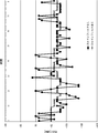
- FIG. It is a graph which shows the application example of the filter which concerns on Embodiment 1.
- FIG. It is a graph which shows the application example of the filter which concerns on Embodiment 1.
- FIG. It is a graph which shows the application example of the filter which concerns on Embodiment 1.
- FIG. It is a graph which shows the application example of the filter which concerns on Embodiment 1.
- FIG. It is a flowchart which shows the operation example of the position estimation system which concerns on Embodiment 1.
- FIG. It is a flowchart which shows the example of the calibration process which concerns on Embodiment 1.
- FIG. It is a figure for demonstrating the calibration process which concerns on Embodiment 1.
- FIG. 1 is a configuration diagram showing a configuration example of a position estimation system according to the present embodiment
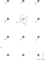
- FIG. 2 is a plan view of an installation area showing an installation example of a receiver
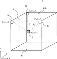
- FIG. 3 is an installation of FIG. It is a perspective view of a part of an example.
- the position estimation system 1 includes a transmitter 2, a plurality of receivers 3, and a position information server 10.
- the position estimation system 1 measures the position of the transmitter 2 by using the beacon signal Bp for position measurement transmitted by the transmitter 2 which is a broadcaster in a room where a plurality of receivers 3 which are observers are installed. It is a system.
- the beacon signal Bp is iBeacon (registered trademark) of Bluetooth Low Energy (BLE).
- BLE Bluetooth Low Energy
- the beacon signal Bp is not limited to Bluetooth, and may be another wireless signal such as a wireless LAN.
- a plurality of receivers 3 are arranged in a matrix in an indoor installation area 5 such as a room at regular intervals in the X and Y directions in a plan view.
- four receivers 3 are arranged in the X direction and three are arranged in the Y direction, for a total of 12 receivers 3.
- the plurality of receivers 3 are not limited to a fixed interval, and may be arranged at an arbitrary interval.
- the space in the installation area 5 surrounded by the three receivers 3a to 3c is the position measurement area 6.
- the receivers 3a to 3c measure the signal strength of the beacon signal Bp received from the transmitter 2, and based on the signal strength, estimate the position of the transmitter 2 in the position measurement area 6 by the three-point positioning method. To do.
- the plurality of receivers 3 may be arranged at arbitrary positions such as the floor and walls of the room, but are as high as the ceiling in order to prevent the beacon signal Bp from the transmitter 2 from being blocked by obstacles. It is preferable to install it in a place. Further, in this example, the receiver 3 is installed indoors, but the receiver 3 may be installed outdoors and the position of the transmitter 2 may be estimated outdoors, not limited to indoors.
- the transmitter 2 transmits the beacon signal Bp in all directions, and the receiver 3 receives it.
- the receiver 3 that has received the beacon signal Bp collects the signal strength at the time of reception, the ID information of the beacon signal Bp, and the like, and then transmits the data to the location information server 10 using Ethernet (registered trademark) or the like. To do.
- the position information server 10 uses the data of the beacon signal Bp received from the receiver 3 to calculate the position of the transmitter 2. By inputting the accurate installation position of the receiver 3 into the position information server 10, the position can be calculated. As described above, the three-point positioning method is used as the method for calculating this position. When the receiver 3 receives the beacon signal Bp, the received signal strength of the beacon signal Bp can be measured, and it is possible to calculate how far away the beacon signal Bp is from this value. In the three-point positioning method, the distance is calculated using the three received signal intensities from the receivers 3 installed at different positions.
- the received signal strength fluctuates greatly depending on the receiving environment such as the presence of obstacles and radio waves that interfere with it, and the error in the calculation result of the position estimation increases. Therefore, the measured value of the received signal strength remains as it is.
- the calculation result fluctuates greatly, and it is difficult to calculate the correct position.
- a method of applying a filter to the received signal strength can be considered in order to improve the position estimation accuracy by suppressing the fluctuation of the received signal strength.
- this method it is possible to reduce the influence of fluctuations in the received signal strength by applying a low-pass filter.
- the problem is how much filter should be applied at what timing, that is, what is the appropriate filter strength. For example, if the filter strength is too strong, fluctuations in the received signal strength are removed more than necessary, so that if the actual position of the transmitter changes, the tracking of the estimated position may be delayed. On the other hand, if the filter strength is too loose, the effect of the filter is diminished, and the error of the estimated position cannot be suppressed.
- the filter strength also referred to as calibration
- the beacon signal Bc for measuring the reception status is arbitrarily used. It has a broadcaster function that transmits at the timing, and temporarily switches from the observer function to the broadcaster function.
- the beacon signal Bc transmitted from the receiver 3b is received by the receivers 3a, 3c to 3i in the vicinity thereof, and the degree of filtering is adjusted according to the reception status of the signal.
- the beacon signal Bc is the same signal as the beacon signal Bp transmitted by the transmitter 2 except for the identification information that identifies the transmitting device. Although an example in which the receiver 3 transmits the beacon signal Bc will be described here, the beacon signal Bc may be transmitted not only from the receiver 3 but also from another device having a fixed position.
- the transmitter 2 is a transmitter that transmits a beacon signal Bp for position measurement, and is a device for position measurement.
- the transmitter 2 includes a beacon transmission unit 21, a CPU (Central Processing Unit) 22, a storage unit 23, and a power supply 24.
- the beacon transmission unit 21 wirelessly transmits the beacon signal Bp according to a communication standard such as BLE.
- the beacon transmission unit 21 periodically broadcasts a beacon signal Bp including ID information that identifies the transmitter 2 to the surroundings.
- the CPU 22 is a control unit that controls each part of the transmitter 2.
- the CPU 22 controls the transmission timing, transmission power, and the like of the beacon signal Bp.
- the storage unit 23 is a storage unit that stores information necessary for the operation of the transmitter 2.
- the storage unit 23 stores ID information and the like of the transmitter 2, which is one of the information to be incorporated in the beacon signal Bp.
- the power supply 24 is a battery power supply or the like for operating the transmitter 2.
- the power supply 24 may be built in the transmitter 2 or may be supplied from the outside.
- the transmitter 2 also has a geomagnetic sensor that detects the orientation of the transmitter 2, a GPS receiver that receives GPS signals, a display that displays information to the user, and encryption / decryption, if necessary.
- a key processing unit or the like may be provided.
- the receiver 3 is a receiver that receives the beacon signal Bp from the transmitter 2 and is also a transmitter that transmits the beacon signal Bc to the surrounding receivers 3.
- the receiver 3 includes a beacon transmission / reception unit 31, a CPU 32, an Ethernet transmission / reception unit 33, and a power supply 34.
- the beacon transmission / reception unit 31 receives the beacon signals Bp and Bc wirelessly transmitted from the transmitter 2 and the other receiver 3 according to a communication standard such as BLE, and further measures the signal strengths of the received beacon signals Bp and Bc. To do. Further, the beacon transmission / reception unit 31 broadcasts the beacon signal Bc including the ID information of the receiver 3 to the surroundings, similarly to the transmitter 2.
- the beacon signal Bc may be transmitted at the timing according to the instruction from the position information server 10, or the beacon signal Bc may be transmitted at the timing determined by the receiver 3.
- the CPU 32 is a control unit that controls each unit of the receiver 3.
- the CPU 32 generates signal strength measurement information to be transmitted to the position information server 10 from the ID information included in the beacon signals Bp and Bc received from the transmitter 2 and the other receiver 3 and the received signal strengths of the beacon signals Bp and Bc. To do.
- the Ethernet transmission / reception unit 33 communicates with the location information server 10 via the network 4 according to the Ethernet standard.
- the Ethernet transmission / reception unit 33 transmits the signal strength measurement information including the ID information of the received beacon signals Bp and Bc and the received signal strength to the position information server 10.
- the power supply 34 is a power supply for operating the receiver 3.
- the power supply 34 may be built in the receiver 3 or may be supplied from the outside.
- the position information server 10 calculates the distance between the transmitter 2 and the receiver 3 based on the received signal strength of the plurality of beacon signals Bp, and determines the distance between the plurality of receivers 3 and the transmitter 2 arranged at different positions. This is a position estimation device that estimates the position of the transmitter 2 based on the calculation result.
- the location information server 10 includes a location information calculation unit 100, a map information management unit 11, a database 12, an Ethernet transmission / reception unit 13, a display unit 14, a CPU 15, and a power supply 16.
- the position information calculation unit 100 calculates the position information of the transmitter 2 based on the signal strength of the beacon signal Bp measured by the plurality of receivers 3.
- the position information calculation unit 100 receives the ID information of the beacon signal Bp transmitted by the transmitter 2 and the signal strength measurement information including the received signal strength from each receiver 3, and on the map of each receiver 3 as shown in FIG.
- the position of the transmitter 2 identified from the ID information is estimated using the distance to the transmitter 2 calculated from the positional relationship of the above and the received signal strength (for example, the distances d 1 , d 2 , d 3).
- the position information calculation unit 100 receives the ID information of the beacon signal Bc transmitted from each receiver 3 by the surrounding receivers 3 and the signal strength measurement information including the received signal strength, and is based on the received signal strength of the beacon signal Bc.
- the reception status of the position measurement area 6 in which the receiver 3 is arranged is determined, and the strength of the filter used for the calculation of the position estimation in the position measurement area 6 is adjusted.
- the map information management unit 11 manages the map information of the database 12.
- the database 12 stores information necessary for processing of the location information server 10.
- the database 12 stores map information, the position of the receiver 3 on the map, the calculated position information of the transmitter 2, and the like.
- the Ethernet transmission / reception unit 13 communicates with a plurality of receivers 3 via the network 4 according to the Ethernet standard.
- the Ethernet transmission / reception unit 13 receives signal strength measurement information including the ID information of the beacon signals Bp and Bc received by each receiver 3 and the received signal strength from the plurality of receivers 3.
- the display unit 14 is a display unit that displays information to the user.
- the display unit 14 superimposes the position information of the transmitter 2 on the map information and displays it. Further, the display unit 14 may display the reception status of each receiver 3.
- the CPU 15 is a control unit that controls each unit of the position information server 10. For example, the CPU 15 controls the display unit 14 to display the position information of the transmitter 2 calculated by the position information calculation unit 100.
- the power supply 16 is a power supply for operating the position information server 10.
- the location information server 10 may also include a key processing unit for encryption / decryption, if necessary.
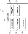
- FIG. 5 shows a configuration example of the position information calculation unit 100 in the position information server 10.
- the position information calculation unit 100 includes a reception status acquisition unit 101, a filter adjustment unit 102, a filter unit 103, a position measurement information acquisition unit 104, and a position estimation unit 105.
- the reception status acquisition unit 101 determines the reception signal strength of the beacon signal Bc transmitted by the other receiver 3 in the position measurement area 6 as the reception status (wireless reception status) in the position measurement area 6 from the plurality of receivers 3. get.
- the filter adjustment unit 102 adjusts the filter strength of the filter unit 103 based on the reception status acquired by the reception status acquisition unit 101, that is, the reception signal strength of the beacon signal Bc by the receiver 3.
- the filter adjusting unit 102 sets the filter strength to be stronger as the reception condition is worse, and the filter strength is set to be weaker as the reception condition is better.
- the filter unit 103 is a low-pass filter that removes noise (fluctuation) components from the received signal strength of the beacon signal Bp by the transmitter 2.
- a Kalman filter is used as an example of a low-pass filter.
- the filter unit 103 executes a filter process on the received signal intensity of the beacon signal Bp by the transmitter 2 by using the Kalman filter having the intensity adjusted by the filter adjusting unit 102.
- the position measurement information acquisition unit 104 acquires the received signal strength of the beacon signal Bp transmitted by the transmitter 2 as the position measurement information for the position measurement of the transmitter 2 from the plurality of receivers 3.
- the position estimation unit 105 estimates the position of the transmitter 2 based on the position measurement information acquired by the position measurement information acquisition unit 104, that is, the reception signal strength of the beacon signal Bp by the transmitter 2.
- the position estimation unit 105 estimates the position of the transmitter 2 in the position measurement region 6 by applying a filter having an intensity adjusted with respect to the reception signal intensity of the beacon signal Bp.
- the position estimation unit 105 uses three received signal intensities of the beacon signal Bp acquired from the plurality of receivers 3 to determine the position of the transmitter 2. calculate. Since it is highly possible that the higher the received signal strength is, the more stable and accurate the value is, for example, the first to third received signal strengths (first to third top) from the largest are used.
- the Kalman filter estimates the current predicted value (X k ) using the current measured value (Z k ) and the previous predicted value (X k-1).
- the received signal strength of the beacon signal Bc transmitted from the receiver 3 is the measured value.
- K in the equation (1) is a Kalman gain, which is obtained by the following equation.
- K (P + Q) / (P + Q + R) ...
- Each parameter in the equation (2) is an estimated value calculated when P predicted last time, Q is the variance of the process noise, and R is the variance of the measured noise.
- the process noise is noise generated when the system transitions, and is assumed to have little effect in this example, and is set to a constant value.
- the measurement noise of the received signal strength changes, so the degree of filtering is adjusted by using the dispersion of the amount of change.
- the receiver 3f receives the beacon signal Bc transmitted from the receiver 3b and the received signal strength is clearly larger than the distance between the receivers 3b-3f, it is between the receivers 3b-3f.
- the reception condition is bad and increase the filter strength. This makes it less susceptible to the unstable received signal strength in the position estimation calculation.
- the filter unit 103 performs the Kalman filter processing by the calculation of the following equations from the above equations (1) and (2).
- X k X k-1 + (P + Q) / (P + Q + R) * (Z k- X k-1 ) ... (3)
- each dispersion value of Q (dispersion of process noise) and R (dispersion of measurement noise) may be actually calculated by measuring data for a certain period of time, or may be actually calculated depending on the operating environment. It may be set to an arbitrary value. For example, Q is fixed and R is changed according to the reception condition to adjust the strength of the filter.
- the noise component can be removed by applying a filter, but the value of the received signal strength also fluctuates when the transmitter is moving. Over-filtering in that case will prevent the system from calculating the current position required. Therefore, in the present embodiment, more accurate position detection is possible by changing the filtering condition according to the radio wave condition.
- a specific example of the filter is shown below.
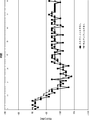
- the graph of FIG. 6 shows an example of the received signal strength when the Kalman filter is applied and when the Kalman filter is not applied in an environment where the reception condition of the radio wave is poor. For example, even though the position of the transmitter does not change, the reception signal strength of the received signal fluctuates greatly because the reception condition of the radio wave is poor.
- the fluctuation of the received signal strength is large, whereas by applying the strong Kalman filter, the fluctuation of the received signal strength is suppressed and the influence of the large noise component is reduced. ing.
- the graph of FIG. 7 shows an example of the received signal strength when the Kalman filter is applied and when the Kalman filter is not applied in an environment where the reception condition of the radio wave is good. For example, when the reception condition of radio waves is good, the position of the transmitter gradually moves away from the receiver.
- the value of the received signal strength gradually decreases as the distance from the receiver increases, and no significant fluctuation is observed.
- the noise component of fine fluctuations is removed while maintaining the gradually decreasing change in the received signal strength.
- FIG. 8 shows the flow of the position estimation method in the position estimation system 1 according to the present embodiment
- FIG. 9 shows the flow of the calibration process (S101) in FIG. 8
- FIG. 10 shows the flow of the calibration process (S101) in FIG.
- the flow of the position estimation process (S102) is shown.
- the position information server 10 first adjusts the filter in the calibration process (S101), and then performs the position estimation process (S102) using the adjusted filter.
- the calibration process is executed at an arbitrary timing when the position estimation process is not performed.
- the function of the receiver 3 is switched (S111). That is, in order to adjust the filter, the function of the receiver 3 is switched from the observer function to the broadcaster function, and the beacon signal Bc is transmitted from the receiver 3.
- the switching of this function may be started by giving each receiver 3 a timer, or may be triggered by a start command from the position information server 10 (for example, the reception status acquisition unit 101).
- the function of each receiver 3 may be switched at predetermined intervals in order to perform calibration on a regular basis. It is preferable to shift the switching timing for each receiver 3 so that the beacon signal Bc transmitted from each receiver 3 does not interfere with each other.
- the location information server 10 acquires the received signal strength from the receiver 3 (S112). That is, when the receiver 3 whose function has been switched transmits the beacon signal Bc, a plurality of receivers 3 around the receiver 3 receive the beacon signal Bc and measure the reception signal strength of the beacon signal Bc. Further, the reception status acquisition unit 101 of the position information calculation unit 100 in the position information server 10 acquires the reception signal strength of the beacon signal Bc from the plurality of receivers 3.
- the position information server 10 adjusts the filter strength according to the received signal strength (S113).
- the filter adjusting unit 102 of the position information calculation unit 100 adjusts the filter strength of the filter unit 103 based on the received signal strength of the beacon signals Bc acquired from the plurality of receivers 3.
- the distance between the broadcaster (receiver that transmits the beacon signal Bc) and the observer (receiver that receives the beacon signal Bc) is calculated from the received signal strength.
- the received signal strength is attenuated in inverse proportion to the square of the distance, the received signal strength measured with the broadcaster and the observer installed apart by a reference distance is used as a reference value.
- iBeacon which is one of the beacon signals
- Measured Power a parameter called Measured Power
- the received signal strength measured with the broadcaster and the observer separated by 1 m is defined as Measured Power
- the received signal strength as a reference is defined as "RSSI @ 1 m”.
- N in this equation (5) is the propagation loss coefficient.
- n is a value that fluctuates depending on the reception environment of radio waves, and is 2 in an ideal environment.
- the position information server 10 Since the position information server 10 needs an accurate position of the receiver 3 indoors when calculating the position of the transmitter 2, for example, the position information server 10 holds the position of each receiver 3 in the database 12 and receives each receiver. The distance between the aircraft 3 is known in advance. Therefore, when the function of the receiver 3 is switched to the transmitter and the beacon signal Bc is transmitted, the value of the received signal strength to be received can be estimated from the surrounding receivers 3 from that distance.
- the filter adjusting unit 102 determines the reception status of the radio wave and adjusts the filter based on the difference between the theoretical value of the received signal strength estimated from this distance and the actually measured value of the received signal strength.
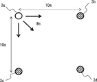
- the receivers 3a to 3d are installed in the positional relationship as shown in FIG. 11, it is assumed that the receivers 3a transmit the beacon signal Bc and the receivers 3b to 3d receive the beacon signals Bc.
- the received signal strength (RSSI @ 1 m) which is the reference when the receiver 3a performs the transmission operation, is ⁇ 50 dBm
- the theoretical value of the received signal strength received by the receiver 3b is the above equation (5).
- the filter adjusting unit 102 compares the theoretical value of the received signal strength with the actually measured received signal strength, and if there is not much difference between the theoretical value and the measured value, determines that the reception condition of the radio wave is good and the filter strength. If there is a large difference between the theoretical value and the measured value, it is judged that the reception condition of the radio wave is bad and the filter strength is increased.
- the settings are made as shown in the table below, and the filter coefficient (R) is set according to the difference between the theoretical value and the measured value of the received signal strength.
- Q is fixed at 0.001.
- R is changed from the difference between the measured value and the theoretical value of the received signal strength of the receiver 3d, but the received signal strength of the receiver 3b or 3c may be used, or all receivers 3b.
- a received signal strength of ⁇ 3d may be used.
- a mathematical formula more suitable for the actual environment may be used.
- the beacon signal may be transmitted a plurality of times in succession, and the average value of the received signal strength may be used for the calculation, or the received signal strength of the beacon signal transmitted after a time may be used. In this way, by changing the degree of filtering according to the reception environment of radio waves, it is possible to calculate the position with high accuracy.
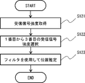
- the position information server 10 acquires the received signal strength from the plurality of receivers 3 (S121). That is, when the transmitter 2 transmits the beacon signal Bp, a plurality of receivers 3 around the transmitter 2 receive the beacon signal Bp and measure the received signal strength of the beacon signal Bp. Further, the position measurement information acquisition unit 104 of the position information calculation unit 100 in the position information server 10 acquires the reception signal strength of the beacon signal Bp from the plurality of receivers 3.
- the location information server 10 selects the first to third received signal strengths (S122).
- the position estimation unit 105 of the position information calculation unit 100 compares the received signal intensities of the plurality of receivers 3 acquired, and sets the received signal intensities used for position estimation by the three-point positioning method among a plurality of received signal intensities. Select the first to third received signal strengths in descending order of received signal strength.
- the position information server 10 estimates the position of the transmitter 2 by using a filter for the selected received signal strength (S123).
- the position estimation unit 105 of the position information calculation unit 100 applies the Kalman filter of the filter unit 103 whose strength is adjusted to the selected first to third received signal strengths, and applies the Kalman filter of the filter unit 103 to the received signal strength to which the filter is applied.
- the three-dimensional position of the transmitter 2 is calculated by the three-point positioning method. In the three-point positioning method, the distance between the transmitter and the receiver is calculated from the received signal strength as in the above equation (5), and the position of the transmitter is estimated based on the calculated distance.
- the position of the transmitter 2 is calculated from the received signal intensities of the receivers 3a to 3c shown in FIG. 3
- the positional relationship between the receiver 3 and the transmitter 2 is represented by a three-dimensional Cartesian coordinate system (X-axis / Y-axis / Z-axis), and the position of the receiver 3a is (x 1 , y 1 , z 1 ).
- the position of the receiver 3b is (x 2 , y 2 , z 2 )
- the position of the receiver 3c is (x 3 , y 3 , z 3 )
- the position of the transmitter 2 is (x T , y T , z T ).
- X-axis / Y-axis / Z-axis the position of the receiver 3a is (x 1 , y 1 , z 1 ).
- the position of the receiver 3b is (x 2 , y 2 , z 2 )
- the position of the receiver 3c is (x 3
- the actual side value of the received signal strength of the receiver 3a when the signal from the transmitter 2 is received is RSSI A
- the actual side value of the received signal strength of the receiver 3b is RSSI B
- the actual received signal strength of the receiver 3c side value and RSSI C.
- Kalman filter processing is applied to the measured values of each received signal strength by Eq. (3). Assuming that the predicted value of each reception intensity is RSSI AXk to RSSI CXk and the previous predicted value of each reception intensity is RSSI AXk-1 to RSSI CXk-1 , RSSI AXk to RSSI CXk are expressed by the following equations.
- RSSI AXk RSSI AXk-1 + (P + Q) / (P + Q + R) * (RSSI A -RSSI AXk-1 ) ...
- RSSI BXk RSSI BXk-1 + (P + Q) / (P + Q + R) * (RSSI B -RSSI BXk-1 ) ...
- RSSI CXk RSSI CXk-1 + (P + Q) / (P + Q + R) * (RSSI C -RSSI CXk-1 ) ...
- the predicted value of the distance between the receiver 3a and the transmitter 2 is d 1XK
- the predicted value of the distance between the receiver 3b and the transmitter 2 is d 2XK
- the predicted value of the distance between the receiver 3c and the transmitter 2 is d 3XK.
- d 1XK to d 3XK can be obtained from the above equation (5) as follows.
- n 2.
- d 1XK 10 ⁇ ⁇ (RSSI @ 1m-RSSI AXK ) / (10 * 2) ⁇ ⁇ ⁇ ⁇ (9)
- d 2XK 10 ⁇ ⁇ (RSSI @ 1m-RSSI BXK ) / (10 * 2) ⁇ ⁇ ⁇ ⁇ (10)
- d 3XK 10 ⁇ ⁇ (RSSI @ 1m-RSSI CXK ) / (10 * 2) ⁇ ... (11)
- the position estimation unit 105 calculates the three-dimensional coordinates of the transmitter 2 by solving the quadratic equations of the equations (12) to (14).
- d 1 the distance between the receiver 3a and the transmitter 2
- d 2 the distance between the receiver 3b and the transmitter 2
- d 1 the distance between the receiver 3c and the transmitter 2
- d 1 the distance between the receiver 3c and the transmitter 2
- n 2.
- d 1 10 ⁇ ⁇ (RSSI @ 1m-RSSI A ) / (10 * 2) ⁇ ⁇ ⁇ ⁇ (15)
- d 2 10 ⁇ ⁇ (RSSI @ 1m-RSSI B ) / (10 * 2) ⁇ ⁇ ⁇ ⁇ (16)
- d 3 10 ⁇ ⁇ (RSSI @ 1m-RSSI C ) / (10 * 2) ⁇ ⁇ ⁇ ⁇ (17)
- the position estimation unit 105 calculates the three-dimensional coordinates of the transmitter 2 by solving the quadratic equations of the equations (21) to (23).
- the filter is not limited to the Kalman filter and may be another low-pass filter.
- the transmitter 2 and the receiver 3 exist in substantially the same plane, and the three-dimensional position is determined.
- the two-dimensional position may be estimated. For example, when it is known that the transmitter and the receiver exist at substantially the same height on the same floor, it is not necessary to estimate the position in the height direction, and a two-dimensional position may be estimated.
- a system that measures the radio wave intensity transmitted by a plurality of receivers and estimates the position of the object by a three-point measurement method using the received signal strength of the measured radio waves.
- a temporal filter is applied to the received signal strength at the time of position estimation, and the strength of this filter is adjusted according to the radio wave condition in the region where the object exists.
- the noise component of the received signal strength can be removed, so that the position can be estimated with higher stability and higher accuracy.
- the noise component of the received signal strength can be appropriately removed by loosening the filter strength when the reception condition of the radio wave is good and increasing the filter strength when the reception condition of the radio wave is bad.
- one of the plurality of receivers is switched to the transmitter, and the signal transmitted from the switched transmitter is received by the other receiver, so that the radio wave condition in the area where the object exists can be determined. evaluate.
- the receiver whose positional relationship is known in advance, evaluate the radio wave condition, and surely adjust the filter.
- Each configuration in the above-described embodiment is composed of hardware and / or software, and may be composed of one hardware or software, or may be composed of a plurality of hardware or software.
- the function (processing) of each device may be realized by a computer having a CPU, a memory, or the like.
- a program for performing the position estimation method in the embodiment may be stored in the storage device, and each function may be realized by executing the program stored in the storage device on the CPU.
- Non-temporary computer-readable media include various types of tangible storage media. Examples of non-temporary computer-readable media include magnetic recording media (eg, flexible disks, magnetic tapes, hard disk drives), magneto-optical recording media (eg, magneto-optical disks), CD-ROMs (Read Only Memory), CD-Rs, Includes CD-R / W, semiconductor memory (for example, mask ROM, PROM (Programmable ROM), EPROM (Erasable PROM), flash ROM, RAM (random access memory)).
- the program may also be supplied to the computer by various types of temporary computer readable media. Examples of temporary computer-readable media include electrical, optical, and electromagnetic waves.
- the temporary computer-readable medium can supply the program to the computer via a wired communication path such as an electric wire and an optical fiber, or a wireless communication path.
- the present invention can be suitably applied to a position estimation device that estimates the position of an electronic device or the like.
- Location estimation system Transmitter 3 Receiver 4 Network 5 Installation area 6 Position measurement area 10 Location information server 11 Map information management unit 12 Database 13 Ethernet transmission / reception unit 14 Display unit 15 CPU 16 Power supply 21 Beacon transmitter 23 Storage unit 24 Power supply 31 Beacon transmitter / receiver 32 CPU 33 Ethernet transmission / reception unit 34 Power supply 100 Position information calculation unit 101 Reception status acquisition unit 102 Filter adjustment unit 103 Filter unit 104 Position measurement information acquisition unit 105 Position estimation unit
Landscapes
- Physics & Mathematics (AREA)
- Engineering & Computer Science (AREA)
- General Physics & Mathematics (AREA)
- Radar, Positioning & Navigation (AREA)
- Remote Sensing (AREA)
- Position Fixing By Use Of Radio Waves (AREA)
Abstract
位置情報サーバ(10)は、発信機(2)から発信された無線信号の受信信号強度に基づいて発信機(2)と受信機(3)との距離を算出し、異なる位置に配置した複数の受信機(3)と発信機(2)との距離の算出結果に基づいて発信機(2)の位置を推定する位置推定装置であって、受信機(3)が受信した受信信号強度の測定値を取得する位置測定情報取得部(104)と、複数の受信機(3)が配置された位置測定領域(6)における無線受信状況を取得する受信状況取得部(101)と、取得された無線受信状況に基づいてフィルタの強度を調整するフィルタ調整部(102)と、調整された強度のフィルタを適用して、位置測定領域(6)における発信機(2)の位置を推定する位置推定部(105)と、を備える。
Description
本発明は、位置推定装置、位置推定方法及び位置推定プログラムに関する。
近年、電子機器の位置を推定する位置推定システムの利用が広がっている。位置推定システムとして、GPS(Global Positioning System)衛星を使用して屋外の位置情報を算出するシステムの他に、GPS衛星の電波が受信できない屋内の位置情報を入手するため、Bluetooth(登録商標)や無線LAN(Local Area Network)信号を用いるシステムが実現されている。
これらのシステムでは、受信信号強度(RSSI:Received Signal Strength Indicator)に基づいて位置を推定する3点測位法が用いられている。関連する技術として、例えば、特許文献1や2が知られている。特許文献1や2などの関連する技術では、複数の受信機を設置した環境において発信機の発信信号を受信し、各受信機が受信した受信信号の信号強度から発信機の位置を推定している。
上記のように関連する技術では、3点測位法により、3点の位置に設置された受信機が受信する信号の信号強度に基づいて発信機の位置を推定する。しかしながら、関連する技術では、発信機と受信機間の環境等によって位置の算出に誤差が生じるため、精度よく位置を推定することが困難であるという課題がある。
本実施形態は、発信機から発信された無線信号の受信信号強度に基づいて前記発信機と受信機との距離を算出し、異なる位置に配置した複数の受信機と前記発信機との距離の算出結果に基づいて前記発信機の位置を推定する位置推定装置であって、前記受信機が受信した受信信号強度の測定値を取得する位置測定情報取得部と、前記複数の受信機が配置された位置測定領域における無線受信状況を取得する受信状況取得部と、前記取得された無線受信状況に基づいてフィルタの強度を調整するフィルタ調整部と、前記調整された強度のフィルタを適用して、前記位置測定領域における前記発信機の位置を推定する位置推定部と、を備える、位置推定装置を提供する。
本実施形態は、発信機から発信された無線信号の受信信号強度に基づいて前記発信機と受信機との距離を算出し、異なる位置に配置した複数の受信機と前記発信機との距離の算出結果に基づいて前記発信機の位置を推定する位置推定方法であって、前記受信機が受信した受信信号強度の測定値を取得し、前記複数の受信機が配置された位置測定領域における無線受信状況を取得し、前記取得された無線受信状況に基づいてフィルタの強度を調整し、前記調整された強度のフィルタを適用して、前記位置測定領域における前記発信機の位置を推定する、位置推定方法を提供する。
本実施形態は、発信機から発信された無線信号の受信信号強度に基づいて前記発信機と受信機との距離を算出し、異なる位置に配置した複数の受信機と前記発信機との距離の算出結果に基づいて前記発信機の位置を推定する処理をコンピュータに実行させるための位置推定プログラムであって、前記受信機が受信した受信信号強度の測定値を取得し、前記複数の受信機が配置された位置測定領域における無線受信状況を取得し、前記取得された無線受信状況に基づいてフィルタの強度を調整し、前記調整された強度のフィルタを適用して、前記位置測定領域における前記発信機の位置を推定する、位置推定プログラムを提供する。
本実施形態によれば、位置の推定精度を向上することが可能な位置推定装置、位置推定方法及び位置推定プログラムを提供することができる。
(実施の形態1)
以下、図面を参照して実施の形態1について説明する。
以下、図面を参照して実施の形態1について説明する。
<システム構成>
図1は、本実施の形態に係る位置推定システムの構成例を示す構成図であり、図2は、受信機の設置例を示す設置エリアの平面図であり、図3は、図2の設置例の一部の斜視図である。
図1は、本実施の形態に係る位置推定システムの構成例を示す構成図であり、図2は、受信機の設置例を示す設置エリアの平面図であり、図3は、図2の設置例の一部の斜視図である。
図1に示すように、本実施の形態に係る位置推定システム1は、発信機2、複数の受信機3、位置情報サーバ10を備える。位置推定システム1は、オブザーバである複数の受信機3が設置された屋内で、ブロードキャスタである発信機2が送信する位置測定用のビーコン信号Bpを用いて、発信機2の位置を測定するシステムである。例えば、ビーコン信号Bpは、Bluetooth Low Energy(BLE)のiBeacon(登録商標)などである。なお、ビーコン信号Bpは、Bluetoothに限らず、無線LAN等のその他の無線信号でもよい。
図2の例では、部屋などの屋内の設置エリア5に、複数の受信機3が、平面視でX方向及びY方向に一定の間隔でマトリクス状に配置されている。例えば、X方向に4個、Y方向に3個配置され、合計12個の受信機3が配置されている。複数の受信機3は、一定の間隔に限らず、任意の間隔で配置されてもよい。図2及び図3に示すように、例えば、3つの受信機3a~3cに囲まれた設置エリア5の中の空間が位置測定領域6となる。受信機3a~3cが、発信機2から受信するビーコン信号Bpの信号強度を測定し、その信号強度に基づいて、位置測定領域6の中で、3点測位法により発信機2の位置を推定する。
なお、複数の受信機3は、部屋の床や壁など任意の位置に配置してもよいが、発信機2からのビーコン信号Bpが障害物によって遮られることを避けるために、天井のような高い場所に設置することが好ましい。また、この例では、屋内に受信機3を設置しているが、屋内に限らず、屋外に受信機3を設置し、屋外で発信機2の位置を推定してもよい。
<システムの検討>
ここで、本実施の形態の理解を助けるため、図1~図3に示したような位置推定システム1において、本実施の形態適用前に生じる問題について検討する。
ここで、本実施の形態の理解を助けるため、図1~図3に示したような位置推定システム1において、本実施の形態適用前に生じる問題について検討する。
位置推定システム1では、発信機2が全方位にビーコン信号Bpを送信し、それを受信機3が受信する。ビーコン信号Bpを受信した受信機3は、受信時の信号強度やビーコン信号BpのID情報などをまとめた上で、位置情報サーバ10に向けてEthernet(登録商標)等を使用してデータを送信する。
位置情報サーバ10は、受信機3から受信したビーコン信号Bpのデータを使用し、発信機2の位置を算出する。受信機3の正確な設置位置を位置情報サーバ10に入力することにより、位置算出が可能となる。上記のように、この位置の算出方法として、3点測位法を用いる。ビーコン信号Bpを受信機3が受信した際に、ビーコン信号Bpの受信信号強度を測定し、この値からどの程度離れた所からビーコン信号Bpが発信されているのかを算出することができる。3点測位法では、それぞれ別の位置に設置した受信機3からの3つの受信信号強度を使って距離を算出する。
しかしながら、Blueooth等の無線通信では、遮蔽物や妨害になる電波の存在などの受信環境によって受信信号強度が大きく変動し、位置推定の算出結果の誤差が膨らむため、受信信号強度の測定値をそのまま使って距離を算出した場合、算出結果の変動が大きく、正しい位置を算出することは困難である。
このような問題に対し、受信信号強度の変動を抑えることで位置の推定精度の向上を図るため、受信信号強度に対しフィルタを適用する方法が考えられる。この方法では、ローパスフィルタをかけることで受信信号強度の変動の影響を減少させることが可能となる。
しかし、フィルタを使用する方法では、どのタイミングでどの程度のフィルタをかけるべきか、すなわち、適切なフィルタ強度がどの程度であるのかが問題となる。例えば、フィルタ強度が強すぎると、受信信号強度の変動を必要以上に除去してしまうため、発信機の実際の位置が変わった場合に、推定位置の追従が遅くなる虞がある。一方、フィルタ強度が緩すぎると、フィルタの効果が薄れてしまうため、推定位置の誤差を抑えることができない。
そこで、本実施の形態では、実際の受信状況に応じたフィルタ強度の調整(キャリブレーションとも言う)を可能とする。具体的には、本実施の形態では、図4に示すように、受信機3が、発信機2からビーコン信号Bpを受信するオブザーバ機能に加えて、受信状況測定用のビーコン信号Bcを任意のタイミングで発信するブロードキャスタ機能を有し、一時的にオブザーバ機能からブロードキャスタ機能に切り替える。例えば、受信機3bから送信されたビーコン信号Bcは、その周辺にある受信機3a、3c~3iによって受信され、その信号の受信状況によって、フィルタのかけ具合を調整する。例えば、受信状況が良い場合はフィルタ強度を緩くし、受信状況が悪い場合はフィルタ強度を強くすることで、適切に誤差の発生を抑える。なお、ビーコン信号Bcは、発信する機器を識別する識別情報以外は、発信機2が発信するビーコン信号Bpと同じ信号である。
なお、ここでは、受信機3がビーコン信号Bcを発信する例について説明するが、受信器3に限らず、位置が固定されたその他の装置からビーコン信号Bcを発信してもよい。
なお、ここでは、受信機3がビーコン信号Bcを発信する例について説明するが、受信器3に限らず、位置が固定されたその他の装置からビーコン信号Bcを発信してもよい。
<装置構成>
次に、図1に示された本実施の形態に係る各装置の構成について説明する。発信機2は、位置測定のためのビーコン信号Bpを発信する発信機であり、位置測定対象の機器である。発信機2は、ビーコン送信部21、CPU(Central Processing Unit)22、記憶部23、電源24を備える。ビーコン送信部21は、BLE等の通信規格にしたがってビーコン信号Bpを無線送信する。ビーコン送信部21は、発信機2を識別するID情報を含むビーコン信号Bpを、定期的に周囲へブロードキャストする。
次に、図1に示された本実施の形態に係る各装置の構成について説明する。発信機2は、位置測定のためのビーコン信号Bpを発信する発信機であり、位置測定対象の機器である。発信機2は、ビーコン送信部21、CPU(Central Processing Unit)22、記憶部23、電源24を備える。ビーコン送信部21は、BLE等の通信規格にしたがってビーコン信号Bpを無線送信する。ビーコン送信部21は、発信機2を識別するID情報を含むビーコン信号Bpを、定期的に周囲へブロードキャストする。
CPU22は、発信機2の各部を制御する制御部である。CPU22は、ビーコン信号Bpの送信タイミングや送信電力等を制御する。記憶部23は、発信機2の動作に必要な情報を記憶する記憶部である。記憶部23には、ビーコン信号Bpに組み込む情報の一つである発信機2のID情報等が記憶されている。電源24は、発信機2が動作するためのバッテリ電源等である。電源24は、発信機2に内蔵されていてもよいし、外部から供給されてもよい。
発信機2は、その他、必要に応じて、発信機2の向きを検出する地磁気センサーや、GPS信号を受信するGPS受信部、ユーザに情報を表示する表示部、暗号化/復号化のためのキー処理部等を備えてもよい。
受信機3は、発信機2からビーコン信号Bpを受信する受信機であるとともに、周囲の受信機3へビーコン信号Bcを発信する発信機でもある。受信機3は、ビーコン送受信部31、CPU32、Ethernet送受信部33、電源34を備える。ビーコン送受信部31は、BLE等の通信規格にしたがって発信機2及び他の受信機3から無線送信されたビーコン信号Bp及びBcを受信し、さらに、受信したビーコン信号Bp及びBcの信号強度を測定する。また、ビーコン送受信部31は、発信機2と同様に、受信機3のID情報を含むビーコン信号Bcを周囲へブロードキャストする。位置情報サーバ10からの指示に従ったタイミングでビーコン信号Bcを送信してもよいし、受信機3の判断するタイミングでビーコン信号Bcを送信してもよい。
CPU32は、受信機3の各部を制御する制御部である。CPU32は、発信機2及び他の受信機3から受信したビーコン信号Bp及びBcに含まれるID情報とビーコン信号Bp及びBcの受信信号強度から、位置情報サーバ10へ送信する信号強度測定情報を生成する。Ethernet送受信部33は、Ethernet規格にしたがい、ネットワーク4を介して位置情報サーバ10と通信を行う。Ethernet送受信部33は、受信したビーコン信号Bp及びBcのID情報と受信信号強度を含む信号強度測定情報を位置情報サーバ10へ送信する。電源34は、受信機3が動作するための電源である。電源34は、受信機3に内蔵されていてもよいし、外部から供給されてもよい。
位置情報サーバ10は、複数のビーコン信号Bpの受信信号強度に基づいて発信機2と受信機3との距離を算出し、異なる位置に配置した複数の受信機3と発信機2との距離の算出結果に基づいて、発信機2の位置を推定する位置推定装置である。位置情報サーバ10は、位置情報演算部100、地図情報管理部11、データベース12、Ethernet送受信部13、表示部14、CPU15、電源16を備える。
位置情報演算部100は、複数の受信機3が測定したビーコン信号Bpの信号強度に基づいて、発信機2の位置情報を演算する。位置情報演算部100は、各受信機3から発信機2が発信したビーコン信号BpのID情報及び受信信号強度を含む信号強度測定情報を受け取り、図3のように、各受信機3の地図上の位置関係と受信信号強度から算出される発信機2までの距離(例えば、距離d1、d2、d3)を使用して、ID情報から識別される発信機2の位置を推定する。また、位置情報演算部100は、各受信機3から周囲の受信機3が発信したビーコン信号BcのID情報及び受信信号強度を含む信号強度測定情報受け取り、ビーコン信号Bcの受信信号強度に基づいて受信機3が配置された位置測定領域6の受信状況を判断し、その位置測定領域6における位置推定の演算に用いるフィルタの強度を調整する。
地図情報管理部11は、データベース12の地図情報を管理する。データベース12は、位置情報サーバ10の処理に必要な情報を記憶する。データベース12は、地図情報や、受信機3の地図上の位置、算出した発信機2の位置情報等を記憶する。Ethernet送受信部13は、Ethernet規格にしたがい、ネットワーク4を介して複数の受信機3と通信を行う。Ethernet送受信部13は、複数の受信機3から、各受信機3が受信したビーコン信号Bp及びBcのID情報及び受信信号強度を含む信号強度測定情報を受信する。
表示部14は、ユーザに情報を表示する表示部である。表示部14は、発信機2の位置情報を地図情報に重ね合わせて表示する。また、表示部14は、各受信機3の受信状況を表示してもよい。CPU15は、位置情報サーバ10の各部を制御する制御部である。例えば、CPU15は、位置情報演算部100が演算した発信機2の位置情報を表示部14に表示するよう制御する。電源16は、位置情報サーバ10が動作するための電源である。位置情報サーバ10は、その他、必要に応じて、暗号化/復号化のためのキー処理部等を備えてもよい。
図5は、位置情報サーバ10における位置情報演算部100の構成例を示している。図5に示すように、位置情報演算部100は、受信状況取得部101、フィルタ調整部102、フィルタ部103、位置測定情報取得部104、位置推定部105を備える。
受信状況取得部101は、複数の受信機3から、位置測定領域6における受信状況(無線受信状況)として、位置測定領域6で他の受信機3により発信されたビーコン信号Bcの受信信号強度を取得する。フィルタ調整部102は、受信状況取得部101が取得した受信状況、すなわち、受信機3によるビーコン信号Bcの受信信号強度に基づいて、フィルタ部103のフィルタ強度を調整する。フィルタ調整部102は、受信状況が悪いほど、フィルタ強度と強く設定し、受信状況が良いほど、フィルタ強度と弱く設定する。
フィルタ部103は、発信機2によるビーコン信号Bpの受信信号強度からノイズ(変動)成分を除去するローパスフィルタである。ここでは、ローパスフィルタの一例としてカルマンフィルタを使用する。本実施形態では、フィルタ部103は、フィルタ調整部102により調整された強度のカルマンフィルタを用いて、発信機2によるビーコン信号Bpの受信信号強度に対しフィルタ処理を実行する。
位置測定情報取得部104は、複数の受信機3から、発信機2の位置測定のための位置測定情報として、発信機2により発信されたビーコン信号Bpの受信信号強度を取得する。位置推定部105は、位置測定情報取得部104が取得した位置測定情報、すなわち、発信機2によるビーコン信号Bpの受信信号強度に基づいて、発信機2の位置を推定する。位置推定部105は、ビーコン信号Bpの受信信号強度に対し調整された強度のフィルタを適用して、位置測定領域6における発信機2の位置を推定する。3点測位法により位置を推定するため、位置推定部105は、複数の受信機3から取得したビーコン信号Bpの受信信号強度のうち、3つの受信信号強度を用いて、発信機2の位置を算出する。受信信号強度は大きい方がより安定した精度のよい値である可能性が高いため、例えば、大きい方から1番目~3番目(上位1番目~3番目)の受信信号強度を用いる。
<フィルタの原理>
次に、本実施の形態のフィルタ部103で使用するカルマンフィルタについて説明する。カルマンフィルタでは、現在の測定値(Zk)と前回の予測値(Xk-1)を使用して、現在の予測値(Xk)を推定する。この例では、受信機3から発信されたビーコン信号Bcの受信信号強度が測定値となる。カルマンフィルタは、下記の式の演算で実現される。
Xk=Xk-1+K(Zk-Xk-1) ・・・(1)
次に、本実施の形態のフィルタ部103で使用するカルマンフィルタについて説明する。カルマンフィルタでは、現在の測定値(Zk)と前回の予測値(Xk-1)を使用して、現在の予測値(Xk)を推定する。この例では、受信機3から発信されたビーコン信号Bcの受信信号強度が測定値となる。カルマンフィルタは、下記の式の演算で実現される。
Xk=Xk-1+K(Zk-Xk-1) ・・・(1)
式(1)におけるKはカルマンゲインであり、以下の式で求められる。
K=(P+Q)/(P+Q+R) ・・・(2)
K=(P+Q)/(P+Q+R) ・・・(2)
式(2)における各パラメータは、Pが前回予測した際に演算した推定値であり、Qがプロセスノイズの分散であり、Rが測定のノイズの分散である。プロセスノイズは、システムが遷移する際に生じるノイズであり、この例ではほとんど影響しないと仮定して、一定値とする。
本実施の形態におけるフィルタの調整では、受信信号強度の測定ノイズが変化するため、その変化量の分散を使用してフィルタのかけ具合を調整する。例えば、図4において、受信機3bから発信したビーコン信号Bcを受信機3fが受信し、その受信信号強度が受信機3b-3f間の距離よりも明らかに大きい場合は受信機3b-3f間の受信状況が悪いと判断し、フィルタ強度を強くする。これにより、位置推定の演算において、安定しない受信信号強度の影響を受け難くする。
具体的には、本実施の形態では、フィルタ部103において、上記式(1)及び式(2)より、以下の式の演算によりカルマンフィルタ処理を行う。
Xk=Xk-1+(P+Q)/(P+Q+R)*(Zk-Xk-1) ・・・(3)
Xk=Xk-1+(P+Q)/(P+Q+R)*(Zk-Xk-1) ・・・(3)
フィルタ調整部102は、上記の式(3)のR(測定のノイズの分散)をビーコン信号Bcの受信状況に応じて変化させる。なお、m個のデータをxi{i=1,2,・・・,m}とし、その平均値をx ̄(バー記号付きのx)とすると、分散は以下の式で求められる。

上記式(3)において、Q(プロセスノイズの分散)及びR(測定のノイズの分散)の各分散値は、一定時間データを測定して実際に算出してもよいし、動作環境に応じて任意の値になるよう設定してもよい。例えば、Qを固定とし、Rを受信状況に応じて変化させてフィルタの強度を調整する。
フィルタをかけることでノイズ成分を除去できるメリットはあるが、発信機が移動している状況では受信信号強度の値も変動する。その場合にフィルタをかけすぎると、このシステムが必要とする現在の位置を算出する妨げになる。このため、本実施の形態では、電波状況に応じてフィルタのかけ具合を変化させることでより精度の高い位置検出を可能とする。以下にフィルタの具体例を示す。
<フィルタの具体例1>
図6のグラフは、電波の受信状況が悪い環境において、カルマンフィルタを適用した場合と適用しない場合の受信信号強度の例を示している。例えば、発信機の位置は変わらないにもかかわらず、電波の受信状況が悪いため、受信信号強度が大きく変動する例である。この例のカルマンフィルタは、受信状況に応じてR=0.1とし、Q=0.001(固定値)として演算している。図6の例では、カルマンフィルタを適用しない場合、受信信号強度の変動が大きいのに対し、強い強度のカルマンフィルタを適用することで、受信信号強度の変動が抑えられ、大きいノイズ成分の影響が軽減されている。
図6のグラフは、電波の受信状況が悪い環境において、カルマンフィルタを適用した場合と適用しない場合の受信信号強度の例を示している。例えば、発信機の位置は変わらないにもかかわらず、電波の受信状況が悪いため、受信信号強度が大きく変動する例である。この例のカルマンフィルタは、受信状況に応じてR=0.1とし、Q=0.001(固定値)として演算している。図6の例では、カルマンフィルタを適用しない場合、受信信号強度の変動が大きいのに対し、強い強度のカルマンフィルタを適用することで、受信信号強度の変動が抑えられ、大きいノイズ成分の影響が軽減されている。
<フィルタの具体例2>
図7のグラフは、電波の受信状況が良い環境において、カルマンフィルタを適用した場合と適用しない場合の受信信号強度の例を示している。例えば、電波の受信状況が良い場合に、発信機の位置が受信機から徐々に離れていく例である。この例のカルマンフィルタは、受信状況に応じてR=0.008とし、Q=0.001(固定値)として演算している。図7の例では、カルマンフィルタを適用しない場合、受信機から遠ざかるにしたがって、徐々に受信信号強度の値が下がっており、大きな変動は見られない。これに対し、弱い強度のカルマンフィルタを適用することで、徐々に低下する受信信号強度の変化を保ちつつ、細かい変動のノイズ成分が除去されている。
図7のグラフは、電波の受信状況が良い環境において、カルマンフィルタを適用した場合と適用しない場合の受信信号強度の例を示している。例えば、電波の受信状況が良い場合に、発信機の位置が受信機から徐々に離れていく例である。この例のカルマンフィルタは、受信状況に応じてR=0.008とし、Q=0.001(固定値)として演算している。図7の例では、カルマンフィルタを適用しない場合、受信機から遠ざかるにしたがって、徐々に受信信号強度の値が下がっており、大きな変動は見られない。これに対し、弱い強度のカルマンフィルタを適用することで、徐々に低下する受信信号強度の変化を保ちつつ、細かい変動のノイズ成分が除去されている。
<位置推定システムの動作>
次に、本実施の形態に係る位置推定システム1の動作例について説明する。図8は、本実施の形態に係る位置推定システム1における位置推定方法の流れを示しており、図9は、図8におけるキャリブレーション処理(S101)の流れを示し、図10は、図8における位置推定処理(S102)の流れを示している。
次に、本実施の形態に係る位置推定システム1の動作例について説明する。図8は、本実施の形態に係る位置推定システム1における位置推定方法の流れを示しており、図9は、図8におけるキャリブレーション処理(S101)の流れを示し、図10は、図8における位置推定処理(S102)の流れを示している。
図8に示すように、位置情報サーバ10は、まず、キャリブレーション処理(S101)にてフィルタを調整し、その後、調整されたフィルタを用いて位置推定処理(S102)を行う。キャリブレーション処理は、位置推定処理が行われない任意のタイミングで実行される。
まず、キャリブレーション処理(S101)では、図9に示すように、受信機3の機能を切り替える(S111)。すなわち、フィルタを調整するため、受信機3の機能をオブザーバ機能からブロードキャスタ機能に切り替え、受信機3からビーコン信号Bcを発信させる。
この機能の切り替えは、各受信機3にタイマーを持たせて起動させてもよいし、位置情報サーバ10(例えば受信状況取得部101)からの起動コマンドをトリガにしてもよい。定期的にキャリブレーションを行うために、各受信機3の機能を所定の間隔で切り替えてもよい。なお、各受信機3から送信されるビーコン信号Bcが干渉しないよう、切り替えのタイミングを受信機3ごとにずらすことが好ましい。
続いて、位置情報サーバ10は、受信機3から受信信号強度を取得する(S112)。すなわち、機能を切り替えた受信機3がビーコン信号Bcを発信すると、その周囲の複数の受信機3がビーコン信号Bcを受信し、ビーコン信号Bcの受信信号強度を測定する。さらに、位置情報サーバ10における位置情報演算部100の受信状況取得部101が、複数の受信機3からビーコン信号Bcの受信信号強度を取得する。
続いて、位置情報サーバ10は、受信信号強度に応じてフィルタ強度を調整する(S113)。位置情報演算部100のフィルタ調整部102は、複数の受信機3から取得したビーコン信号Bcの受信信号強度に基づいて、フィルタ部103のフィルタ強度を調整する。
このとき、受信信号強度からブロードキャスタ(ビーコン信号Bcを発信する受信機)とオブザーバ(ビーコン信号Bcを受信する受信機)の間の距離を算出する。この距離の算出では、受信信号強度が距離の2乗に反比例して減衰することから、ブロードキャスタとオブザーバを基準となる距離だけ離して設置した状態で測定した受信信号強度を基準値として用いる。
例えば、ビーコン信号の一つであるiBeaconの信号内には、いくつかの情報が組み込まれており、その中にMeasured Powerと呼ばれるパラメータが含まれる。iBeaconの場合、ブロードキャスタとオブザーバを1m離して測定した受信信号強度をMeasured Powerと定義しており、この基準となる受信信号強度を「RSSI@1m」とする。そうすると、基準となる受信信号強度と実際に測定した受信信号強度(RSSI)から、以下のような式でブロードキャスタとオブザーバの距離(d)が算出できる。
d=10^{(RSSI@1m-RSSI)/(10*n)} ・・・(5)
d=10^{(RSSI@1m-RSSI)/(10*n)} ・・・(5)
この式(5)内のnは伝搬損失係数である。nは、電波の受信環境によって変動する値であり、理想的な環境では2となる。
位置情報サーバ10は、発信機2の位置を計算する際に屋内の受信機3の正確な位置が必要となるため、例えば、データベース12に各受信機3の位置を保持しており、各受信機3の間の距離を予め把握している。よって、受信機3の機能が発信機に切り替わってビーコン信号Bcを送信した場合、周囲にある受信機3はその距離から受信すべき受信信号強度の値が推測できる。フィルタ調整部102は、この距離から推測される受信信号強度の理論値と、実際に測定した受信信号強度の測定値との差に基づいて、電波の受信状況を判断しフィルタを調整する。
例えば、図11に示すような位置関係で受信機3a~3dが設置されている場合に、受信機3aがビーコン信号Bcを発信し、受信機3b~3dがビーコン信号Bcを受信したとする。このとき、受信機3aが発信動作をする際の基準となる受信信号強度(RSSI@1m)を-50dBmとすると、受信機3bが受信する受信信号強度の理論値は、上記式(5)を用いて、受信機3b~3dの距離(10m)から、以下のように計算できる。
10[m]=10^{(-50-RSSI)/(10*2)}
RSSI=-50-20*log10
=-70[dBm]
10[m]=10^{(-50-RSSI)/(10*2)}
RSSI=-50-20*log10
=-70[dBm]
同様に受信機3c及び3dの受信する受信信号強度の理論値を求めると以下の表のようになる。
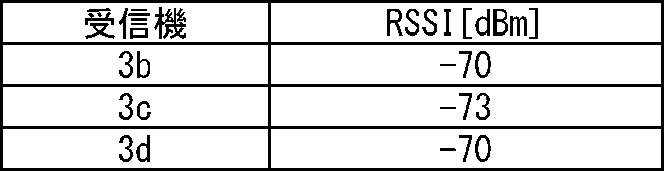
フィルタ調整部102は、この受信信号強度の理論値と実際に測定された受信信号強度を比較し、理論値と測定値にあまり差がない場合は電波の受信状況が良いと判断してフィルタ強度を弱くし、理論値と測定値に大きく差がある場合は電波の受信状況が悪いと判断してフィルタ強度を強くする。
一例として以下の表ように設定し、受信信号強度の理論値と測定値の差に応じてフィルタ係数(R)を設定する。なお、この例では、Qを0.001に固定する。
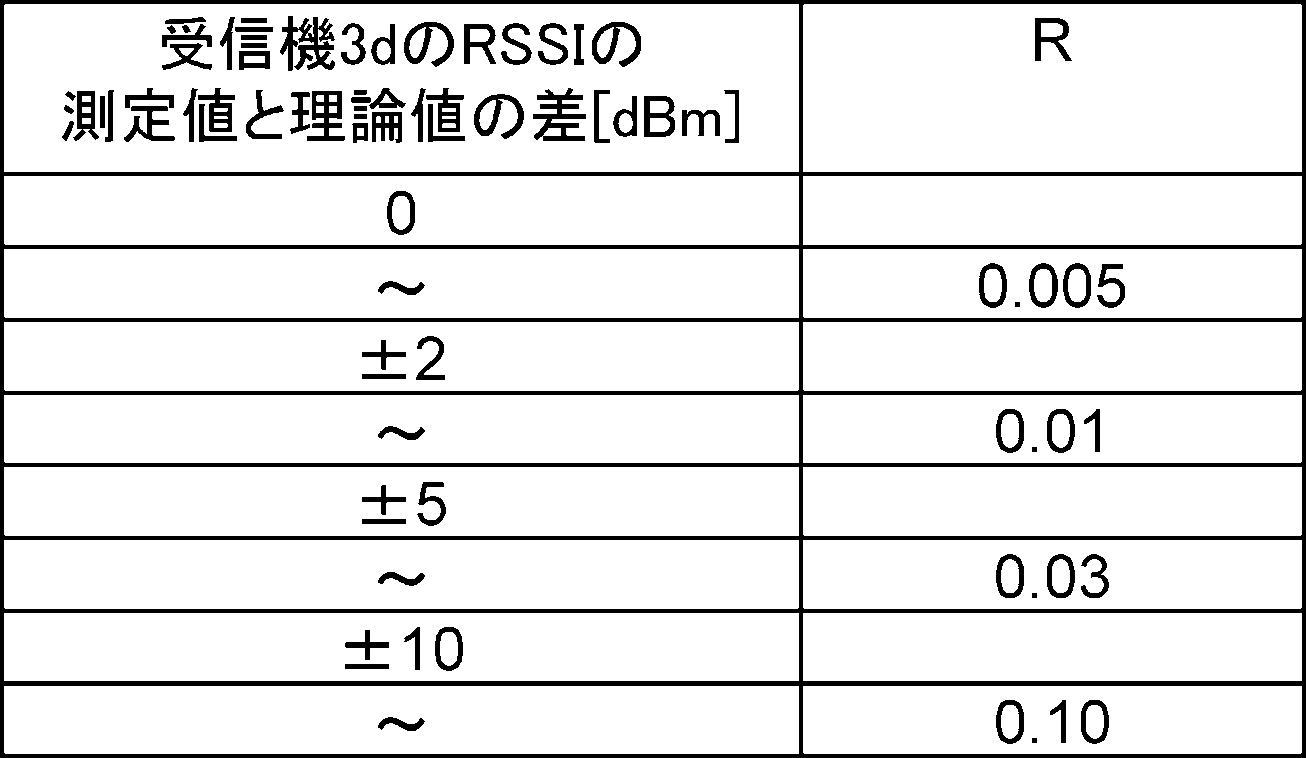
上記表2は受信機3dの受信信号強度の測定値と理論値の差からRを変化させているが、受信機3bもしくは3cの受信信号強度を使用してもよいし、全ての受信機3b~3dの受信信号強度を使用してもよい。また、受信機3の受信信号強度の測定値と理論値の単純な差ではなく、より現実の環境に適した数式を使用してもよい。さらに、連続して複数回ビーコン信号を送信させ、その受信信号強度の平均値を算出に用いてもよいし、時間をおいて送信したビーコン信号の受信信号強度を使用してもよい。このように、電波の受信環境にあわせてフィルタのかけ具合を変化させることで、精度よく位置算出することが可能となる。
次に、キャリブレーション処理に続いて、位置推定処理(S102)では、図10に示すように、位置情報サーバ10は、複数の受信機3から受信信号強度を取得する(S121)。すなわち、発信機2がビーコン信号Bpを発信すると、その周囲の複数の受信機3がビーコン信号Bpを受信し、ビーコン信号Bpの受信信号強度を測定する。さらに、位置情報サーバ10における位置情報演算部100の位置測定情報取得部104が、複数の受信機3からビーコン信号Bpの受信信号強度を取得する。
続いて、位置情報サーバ10は、1番目から3番目の受信信号強度を選択する(S122)。位置情報演算部100の位置推定部105は、取得した複数の受信機3の受信信号強度を比較し、3点測位法による位置の推定に使用する受信信号強度として、複数の受信信号強度の中から受信信号強度が強い順に1番目~3番目の受信信号強度を選択する。
続いて、位置情報サーバ10は、選択した受信信号強度に対しフィルタを使用して、発信機2の位置を推定する(S123)。位置情報演算部100の位置推定部105は、選択した1番目~3番目の受信信号強度に対し、強度が調整されているフィルタ部103のカルマンフィルタを適用し、フィルタが適用された受信信号強度に基づいて3点測位法により発信機2の3次元位置を算出する。3点測位法では、上記式(5)のように、受信信号強度から発信機と受信機の間の距離を算出し、算出された距離に基づいて発信機の位置を推定する。
例えば、図3に示した受信機3a~3cの受信信号強度から発信機2の位置を算出する場合について説明する。このとき、受信機3及び発信機2の位置関係を3次元直交座標系(X軸/Y軸/Z軸)で表現し、受信機3aの位置を(x1,y1,z1)、受信機3bの位置を(x2,y2,z2)、受信機3cの位置を(x3,y3,z3)、発信機2の位置を(xT,yT,zT)とする。発信機2からの信号を受信したときの受信機3aの受信信号強度の実側値をRSSIA、受信機3bの受信信号強度の実側値をRSSIB、受信機3cの受信信号強度の実側値をRSSICとする。各受信信号強度の実測値に対し(3)式によりカルマンフィルタ処理を適用する。各受信強度の予測値をRSSIAXk~RSSICXk、各受信強度の前回の予測値をRSSIAXk-1~RSSICXk-1とすると、RSSIAXk~RSSICXkは下記式で表される。
RSSIAXk=RSSIAXk-1+(P+Q)/(P+Q+R)*(RSSIA-RSSIAXk-1) ・・・(6)
RSSIBXk=RSSIBXk-1+(P+Q)/(P+Q+R)*(RSSIB-RSSIBXk-1) ・・・(7)
RSSICXk=RSSICXk-1+(P+Q)/(P+Q+R)*(RSSIC-RSSICXk-1) ・・・(8)
RSSIAXk=RSSIAXk-1+(P+Q)/(P+Q+R)*(RSSIA-RSSIAXk-1) ・・・(6)
RSSIBXk=RSSIBXk-1+(P+Q)/(P+Q+R)*(RSSIB-RSSIBXk-1) ・・・(7)
RSSICXk=RSSICXk-1+(P+Q)/(P+Q+R)*(RSSIC-RSSICXk-1) ・・・(8)
受信機3aと発信機2間の距離の予測値をd1XK、受信機3bと発信機2間の距離の予測値をd2XK、受信機3cと発信機2間の距離の予測値をd3XKとすると、d1XK~d3XKは、上記式(5)より、下記のように求められる。ここでは、n=2とする。
d1XK=10^{(RSSI@1m-RSSIAXK)/(10*2)} ・・・(9)
d2XK=10^{(RSSI@1m-RSSIBXK)/(10*2)} ・・・(10)
d3XK=10^{(RSSI@1m-RSSICXK)/(10*2)} ・・・(11)
d1XK=10^{(RSSI@1m-RSSIAXK)/(10*2)} ・・・(9)
d2XK=10^{(RSSI@1m-RSSIBXK)/(10*2)} ・・・(10)
d3XK=10^{(RSSI@1m-RSSICXK)/(10*2)} ・・・(11)
さらに、上記式(9)~(11)によるd1XK~d3XKと、受信機3a~3cと発信機2の3次元座標の距離を使用して、方程式を立てると以下のようになる。
{(x1-xT)2+(y1-yT)2+(z1-zT)2}1/2=d1XK ・・・(12)
{(x2-xT)2+(y2-yT)2+(z2-zT)2}1/2=d2XK ・・・(13)
{(x3-xT)2+(y3-yT)2+(z3-zT)2}1/2=d3XK ・・・(14)
{(x1-xT)2+(y1-yT)2+(z1-zT)2}1/2=d1XK ・・・(12)
{(x2-xT)2+(y2-yT)2+(z2-zT)2}1/2=d2XK ・・・(13)
{(x3-xT)2+(y3-yT)2+(z3-zT)2}1/2=d3XK ・・・(14)
式(12)~(14)において、xT、yT、zT以外のパラメータは既知である。このため、位置推定部105は、式(12)~(14)の3元2次方程式を解くことで発信機2の3次元座標を算出する。
(変形例)
上記実施形態では各受信信号強度の実測値に対しフィルタを適用する例を説明したが、各受信信号強度の実測値に対しフィルタを適用する代わりに、各受信信号強度の実測値に基づいて算出した距離に対しフィルタを適用しても良い。
上記実施形態では各受信信号強度の実測値に対しフィルタを適用する例を説明したが、各受信信号強度の実測値に対しフィルタを適用する代わりに、各受信信号強度の実測値に基づいて算出した距離に対しフィルタを適用しても良い。
図3に示した受信機3a~3cの受信信号強度から発信機2の位置を算出する場合について説明する。
各受信強度の実測値から算出した、受信機3aと発信機2間の距離をd1、受信機3bと発信機2間の距離をd2、受信機3cと発信機2間の距離をd3とすると、d1~d3は、上記式(5)より、以下の式から求められる。ここでは、n=2とする。
d1=10^{(RSSI@1m-RSSIA)/(10*2)} ・・・(15)
d2=10^{(RSSI@1m-RSSIB)/(10*2)} ・・・(16)
d3=10^{(RSSI@1m-RSSIC)/(10*2)} ・・・(17)
各受信強度の実測値から算出した、受信機3aと発信機2間の距離をd1、受信機3bと発信機2間の距離をd2、受信機3cと発信機2間の距離をd3とすると、d1~d3は、上記式(5)より、以下の式から求められる。ここでは、n=2とする。
d1=10^{(RSSI@1m-RSSIA)/(10*2)} ・・・(15)
d2=10^{(RSSI@1m-RSSIB)/(10*2)} ・・・(16)
d3=10^{(RSSI@1m-RSSIC)/(10*2)} ・・・(17)
d1~d3に対し(3)式によりカルマンフィルタを適用する。各距離の予測値をd1XK'~d3XK'、各距離の前回の予測値をd1XK-1'~d3XK-1'とすると、d1XK'~d3XK'は、下記式で表される。
d1XK'=d1XK-1'+(P+Q)/(P+Q+R)*(d1-d1XK-1')・・・(18)
d2XK'=d2XK-1'+(P+Q)/(P+Q+R)*(d2-d2XK-1')・・・(19)
d3XK'=d3XK-1'+(P+Q)/(P+Q+R)*(d3-d3XK-1')・・・(20)
d1XK'=d1XK-1'+(P+Q)/(P+Q+R)*(d1-d1XK-1')・・・(18)
d2XK'=d2XK-1'+(P+Q)/(P+Q+R)*(d2-d2XK-1')・・・(19)
d3XK'=d3XK-1'+(P+Q)/(P+Q+R)*(d3-d3XK-1')・・・(20)
上記式(18)~(20)によるd1XK'~d3XK'と、受信機3a~3cと発信機2の3次元座標の距離を使用して、方程式を立てると以下のようになる。
{(x1-xT)2+(y1-yT)2+(z1-zT)2}1/2=d1XK' ・・・(21)
{(x2-xT)2+(y2-yT)2+(z2-zT)2}1/2=d2XK' ・・・(22)
{(x3-xT)2+(y3-yT)2+(z3-zT)2}1/2=d3XK' ・・・(23)
位置推定部105は、式(21)~(23)の3元2次方程式を解くことで発信機2の3次元座標を算出する。
{(x1-xT)2+(y1-yT)2+(z1-zT)2}1/2=d1XK' ・・・(21)
{(x2-xT)2+(y2-yT)2+(z2-zT)2}1/2=d2XK' ・・・(22)
{(x3-xT)2+(y3-yT)2+(z3-zT)2}1/2=d3XK' ・・・(23)
位置推定部105は、式(21)~(23)の3元2次方程式を解くことで発信機2の3次元座標を算出する。
上記実施形態ではカルマンフィルタを用いる例を説明したが、フィルタはカルマンフィルタに限定されず、他のローパスフィルタであっても良い。
上記実施形態では、送信機2の3次元的な位置を推定する例を説明したが、送信機2と受信機3がほぼ同一平面状に存在することが予め判っていて3次元的な位置を推定する必要がない場合等は、2次元的な位置を推定すれば良い。例えば、送信機と受信機が同じフロアのほぼ同じ高さに存在することが判っている場合、高さ方向の位置は推定する必要が無く、2次元的な位置を推定すれば良い。
<本実施の形態の効果>
以上のように、本実施の形態では、複数の受信機により対象物の発信する電波強度を測定し、測定した電波の受信信号強度を使って3点測定法により対象物の位置を推定するシステムにおいて、位置推定時に受信信号強度に対し時間的なフィルタを適用し、このフィルタの強度を対象物が存在する領域の電波状況に応じて調整する。これにより、受信信号強度のノイズ成分を除去できるため、より安定度が高く、高い精度で位置を推定することができる。特に、電波の受信状況が良い場合はフィルタ強度を緩くし、電波の受信状況が悪い場合はフィルタ強度を強くすることで、受信信号強度のノイズ成分を適切に除去することができる。
以上のように、本実施の形態では、複数の受信機により対象物の発信する電波強度を測定し、測定した電波の受信信号強度を使って3点測定法により対象物の位置を推定するシステムにおいて、位置推定時に受信信号強度に対し時間的なフィルタを適用し、このフィルタの強度を対象物が存在する領域の電波状況に応じて調整する。これにより、受信信号強度のノイズ成分を除去できるため、より安定度が高く、高い精度で位置を推定することができる。特に、電波の受信状況が良い場合はフィルタ強度を緩くし、電波の受信状況が悪い場合はフィルタ強度を強くすることで、受信信号強度のノイズ成分を適切に除去することができる。
また、本実施の形態では、複数の受信機のいずれかを発信機に切り替え、切り替えた発信機から発信する信号を他の受信機で受信することで、対象物が存在する領域の電波状況を評価する。これにより、位置関係が予めわかっている受信機を効果的に利用して、電波状況を評価し、確実にフィルタを調整することができる。
なお、本発明は上記実施の形態に限られたものではなく、趣旨を逸脱しない範囲で適宜変更することが可能である。
上述の実施形態における各構成は、ハードウェア又はソフトウェア、もしくはその両方によって構成され、1つのハードウェア又はソフトウェアから構成してもよいし、複数のハードウェア又はソフトウェアから構成してもよい。各装置の機能(処理)を、CPUやメモリ等を有するコンピュータにより実現してもよい。例えば、記憶装置に実施形態における位置推定方法を行うためのプログラムを格納し、各機能を、記憶装置に格納されたプログラムをCPUで実行することにより実現してもよい。
これらのプログラムは、様々なタイプの非一時的なコンピュータ可読媒体(non-transitory computer readable medium)を用いて格納され、コンピュータに供給することができる。非一時的なコンピュータ可読媒体は、様々なタイプの実体のある記録媒体(tangible storage medium)を含む。非一時的なコンピュータ可読媒体の例は、磁気記録媒体(例えばフレキシブルディスク、磁気テープ、ハードディスクドライブ)、光磁気記録媒体(例えば光磁気ディスク)、CD-ROM(Read Only Memory)、CD-R、CD-R/W、半導体メモリ(例えば、マスクROM、PROM(Programmable ROM)、EPROM(Erasable PROM)、フラッシュROM、RAM(random access memory))を含む。また、プログラムは、様々なタイプの一時的なコンピュータ可読媒体(transitory computer readable medium)によってコンピュータに供給されてもよい。一時的なコンピュータ可読媒体の例は、電気信号、光信号、及び電磁波を含む。一時的なコンピュータ可読媒体は、電線及び光ファイバ等の有線通信路、又は無線通信路を介して、プログラムをコンピュータに供給できる。
この出願は、2019年12月2日に出願された日本出願特願2019-217716を基礎とする優先権を主張し、その開示の全てをここに取り込む。
本発明は、電子機器等の位置を推定する位置推定装置に好適に適用することができる。
1 位置推定システム
2 発信機
3 受信機
4 ネットワーク
5 設置エリア
6 位置測定領域
10 位置情報サーバ
11 地図情報管理部
12 データベース
13 Ethernet送受信部
14 表示部
15 CPU
16 電源
21 ビーコン送信部
23 記憶部
24 電源
31 ビーコン送受信部
32 CPU
33 Ethernet送受信部
34 電源
100 位置情報演算部
101 受信状況取得部
102 フィルタ調整部
103 フィルタ部
104 位置測定情報取得部
105 位置推定部
2 発信機
3 受信機
4 ネットワーク
5 設置エリア
6 位置測定領域
10 位置情報サーバ
11 地図情報管理部
12 データベース
13 Ethernet送受信部
14 表示部
15 CPU
16 電源
21 ビーコン送信部
23 記憶部
24 電源
31 ビーコン送受信部
32 CPU
33 Ethernet送受信部
34 電源
100 位置情報演算部
101 受信状況取得部
102 フィルタ調整部
103 フィルタ部
104 位置測定情報取得部
105 位置推定部
Claims (10)
- 発信機から発信された無線信号の受信信号強度に基づいて前記発信機と受信機との距離を算出し、異なる位置に配置した複数の受信機と前記発信機との距離の算出結果に基づいて前記発信機の位置を推定する位置推定装置であって、
前記受信機が受信した受信信号強度の測定値を取得する位置測定情報取得部と、
前記複数の受信機が配置された位置測定領域における無線受信状況を取得する受信状況取得部と、
前記取得された無線受信状況に基づいてフィルタの強度を調整するフィルタ調整部と、
前記調整された強度のフィルタを適用して、前記位置測定領域における前記発信機の位置を推定する位置推定部と、
を備える、位置推定装置。 - 前記フィルタ調整部は、前記無線受信状況が悪いほど、前記フィルタの強度を強くする、
請求項1に記載の位置推定装置。 - 前記位置推定部は、前記受信信号強度の測定値に対し前記フィルタを適用する、
請求項1または2に記載の位置推定装置。 - 前記位置推定部は、前記受信信号強度に基づいて算出した前記発信機と前記受信機との距離に対し前記フィルタを適用する、
請求項1または2に記載の位置推定装置。 - 前記無線受信状況は、前記位置測定領域において前記受信機が受信した受信状況測定用の無線信号の受信信号強度である、
請求項1乃至4のいずれか一項に記載の位置推定装置。 - 前記フィルタ調整部は、前記受信状況測定用の無線信号の受信信号強度の測定値と理論値の差に基づいて、前記フィルタの強度を調整する、
請求項5に記載の位置推定装置。 - 前記フィルタは、前記調整された強度に応じて、前記受信信号強度のノイズ成分を除去するローパスフィルタである、
請求項1乃至6のいずれか一項に記載の位置推定装置。 - 前記ローパスフィルタは、カルマンフィルタであり、
前記フィルタ調整部は、前記無線受信状況に応じて、前記カルマンフィルタのカルマンゲインのパラメータである測定ノイズ分散値を調整する、
請求項7に記載の位置推定装置。 - 発信機から発信された無線信号の受信信号強度に基づいて前記発信機と受信機との距離を算出し、異なる位置に配置した複数の受信機と前記発信機との距離の算出結果に基づいて前記発信機の位置を推定する位置推定方法であって、
前記受信機が受信した受信信号強度の測定値を取得し、
前記複数の受信機が配置された位置測定領域における無線受信状況を取得し、
前記取得された無線受信状況に基づいてフィルタの強度を調整し、
前記調整された強度のフィルタを適用して、前記位置測定領域における前記発信機の位置を推定する、
位置推定方法。 - 発信機から発信された無線信号の受信信号強度に基づいて前記発信機と受信機との距離を算出し、異なる位置に配置した複数の受信機と前記発信機との距離の算出結果に基づいて前記発信機の位置を推定する処理をコンピュータに実行させるための位置推定プログラムであって、
前記受信機が受信した受信信号強度の測定値を取得し、
前記複数の受信機が配置された位置測定領域における無線受信状況を取得し、
前記取得された無線受信状況に基づいてフィルタの強度を調整し、
前記調整された強度のフィルタを適用して、前記位置測定領域における前記発信機の位置を推定する、
位置推定プログラム。
Applications Claiming Priority (2)
| Application Number | Priority Date | Filing Date | Title |
|---|---|---|---|
| JP2019217716A JP2021089144A (ja) | 2019-12-02 | 2019-12-02 | 位置推定装置、位置推定方法及び位置推定プログラム |
| JP2019-217716 | 2019-12-02 |
Publications (1)
| Publication Number | Publication Date |
|---|---|
| WO2021111862A1 true WO2021111862A1 (ja) | 2021-06-10 |
Family
ID=76220002
Family Applications (1)
| Application Number | Title | Priority Date | Filing Date |
|---|---|---|---|
| PCT/JP2020/042762 Ceased WO2021111862A1 (ja) | 2019-12-02 | 2020-11-17 | 位置推定装置、位置推定方法及び位置推定プログラム |
Country Status (2)
| Country | Link |
|---|---|
| JP (1) | JP2021089144A (ja) |
| WO (1) | WO2021111862A1 (ja) |
Cited By (1)
| Publication number | Priority date | Publication date | Assignee | Title |
|---|---|---|---|---|
| WO2022158070A1 (ja) * | 2021-01-21 | 2022-07-28 | パナソニックIpマネジメント株式会社 | 測位方法、プログラム及び測位システム |
Families Citing this family (1)
| Publication number | Priority date | Publication date | Assignee | Title |
|---|---|---|---|---|
| WO2025062530A1 (ja) * | 2023-09-20 | 2025-03-27 | 日本電信電話株式会社 | 位置決定方法及びシステム |
Citations (4)
| Publication number | Priority date | Publication date | Assignee | Title |
|---|---|---|---|---|
| JP2008122132A (ja) * | 2006-11-09 | 2008-05-29 | Yamatake Corp | 位置推定方法および位置推定システム |
| JP2015158492A (ja) * | 2014-02-21 | 2015-09-03 | 株式会社リコー | 無線通信装置間の距離を算出する方法とシステム |
| WO2016199254A1 (ja) * | 2015-06-10 | 2016-12-15 | 三菱電機株式会社 | 位置推定装置および位置推定方法 |
| JP6347533B1 (ja) * | 2018-02-16 | 2018-06-27 | タメコ株式会社 | 位置特定方法、位置特定装置およびプログラム |
-
2019
- 2019-12-02 JP JP2019217716A patent/JP2021089144A/ja active Pending
-
2020
- 2020-11-17 WO PCT/JP2020/042762 patent/WO2021111862A1/ja not_active Ceased
Patent Citations (4)
| Publication number | Priority date | Publication date | Assignee | Title |
|---|---|---|---|---|
| JP2008122132A (ja) * | 2006-11-09 | 2008-05-29 | Yamatake Corp | 位置推定方法および位置推定システム |
| JP2015158492A (ja) * | 2014-02-21 | 2015-09-03 | 株式会社リコー | 無線通信装置間の距離を算出する方法とシステム |
| WO2016199254A1 (ja) * | 2015-06-10 | 2016-12-15 | 三菱電機株式会社 | 位置推定装置および位置推定方法 |
| JP6347533B1 (ja) * | 2018-02-16 | 2018-06-27 | タメコ株式会社 | 位置特定方法、位置特定装置およびプログラム |
Non-Patent Citations (3)
| Title |
|---|
| OGAWARA, RYO ET AL.: "A study on location estimation system combining GPS positioning and movement estimation by sensors", IEICE TECHNICAL REPORT, vol. 113, no. 336, 26 November 2013 (2013-11-26), pages 1 - 6, ISSN: 0913-5685 * |
| ROEBESAAT, JENNY ET AL.: "An Improved BLE Indoor Localization with Kalman-Based Fusion: An Experimental Study", SENSORS, vol. 17, no. 5, 26 April 2017 (2017-04-26), XP055834783, Retrieved from the Internet <URL:https://www.mdpi.com/1424-8220/17/5/951> [retrieved on 20210127], DOI: 10.3390/s17050951 * |
| ZHANG, KAIBI ET AL.: "Research of RSSI Indoor Ranging Algorithm Based on Gaussian - Kalman Linear Filtering", 2016 IEEE ADVANCED INFORMATION MANAGEMENT, COMMUNICATES, ELECTRONIC AND AUTOMATION CONTROL CONFERENCE (IMCEC, 3 October 2016 (2016-10-03), pages 1628 - 1632, XP033070963, DOI: 10.1109/ IMCEC.2016.7867493 * |
Cited By (3)
| Publication number | Priority date | Publication date | Assignee | Title |
|---|---|---|---|---|
| WO2022158070A1 (ja) * | 2021-01-21 | 2022-07-28 | パナソニックIpマネジメント株式会社 | 測位方法、プログラム及び測位システム |
| JPWO2022158070A1 (ja) * | 2021-01-21 | 2022-07-28 | ||
| JP7627898B2 (ja) | 2021-01-21 | 2025-02-07 | パナソニックIpマネジメント株式会社 | 測位方法、プログラム及び測位システム |
Also Published As
| Publication number | Publication date |
|---|---|
| JP2021089144A (ja) | 2021-06-10 |
Similar Documents
| Publication | Publication Date | Title |
|---|---|---|
| US20220224427A1 (en) | Wireless radio device alignment tools and methods | |
| Choi et al. | Calibration-free positioning technique using Wi-Fi ranging and built-in sensors of mobile devices | |
| US9143954B2 (en) | Position identification apparatus, position identification method, position identification system, recording medium, air conditioning system, and lighting system | |
| Sadowski et al. | Optimization of BLE beacon density for RSSI-based indoor localization | |
| KR101555995B1 (ko) | 다중 기준국 기반의 위성항법 기만신호의 검출 및 위치 추정 방법 및 장치 | |
| Moghtadaiee et al. | WiFi fingerprinting signal strength error modeling for short distances | |
| US12027884B2 (en) | Information processing device, information processing system, data generation method, and non-transitory computer readable medium | |
| KR101247964B1 (ko) | 비콘을 이용한 전파식별 리더의 위치 측정 방법 및 그를 위한 전파식별 시스템 | |
| JP2014215134A (ja) | 位置推定装置、位置推定方法、及び無線通信システム | |
| Mukhopadhyay et al. | Novel RSSI evaluation models for accurate indoor localization with sensor networks | |
| US12204041B2 (en) | Location estimation apparatus, location estimation method, and program for location estimation | |
| KR20170108376A (ko) | 무선 통신 시스템에서 액세스 포인트를 이용한 위치 추정 방법 및 장치 | |
| US12200573B2 (en) | Location estimation apparatus, location estimation method, and non-transitory computer readable medium storing program for location estimation | |
| JP4254929B2 (ja) | 位置決定方法およびシステム | |
| WO2021111862A1 (ja) | 位置推定装置、位置推定方法及び位置推定プログラム | |
| KR20180010545A (ko) | 위치 측정 시스템 및 방법 | |
| KR20180059094A (ko) | 비콘 기반 실내 측위에서의 rssi 보정 방법 및 시스템 | |
| Nguyen et al. | Optimized indoor positioning for static mode smart devices using BLE | |
| KR20150125533A (ko) | 무선 위치 추정 장치 및 그 방법 | |
| JP2012002734A (ja) | 位置検出装置、方法及びプログラム | |
| WO2020209053A1 (ja) | 位置推定方法、位置推定システム、位置推定サーバおよび位置推定プログラム | |
| JP2013506144A (ja) | 無線測位方法 | |
| CN105793724A (zh) | 提高wi-fi技术定位精度的方法和装置 | |
| CN108254719A (zh) | 一种适用于电磁频谱监测系统的信号源定位方法 | |
| JP2022149266A (ja) | 位置推定装置、位置推定方法及び位置推定プログラム |
Legal Events
| Date | Code | Title | Description |
|---|---|---|---|
| 121 | Ep: the epo has been informed by wipo that ep was designated in this application |
Ref document number: 20896838 Country of ref document: EP Kind code of ref document: A1 |
|
| DPE1 | Request for preliminary examination filed after expiration of 19th month from priority date (pct application filed from 20040101) | ||
| NENP | Non-entry into the national phase |
Ref country code: DE |
|
| 122 | Ep: pct application non-entry in european phase |
Ref document number: 20896838 Country of ref document: EP Kind code of ref document: A1 |