WO2021106989A1 - 圧縮機の油供給システム - Google Patents
圧縮機の油供給システム Download PDFInfo
- Publication number
- WO2021106989A1 WO2021106989A1 PCT/JP2020/043970 JP2020043970W WO2021106989A1 WO 2021106989 A1 WO2021106989 A1 WO 2021106989A1 JP 2020043970 W JP2020043970 W JP 2020043970W WO 2021106989 A1 WO2021106989 A1 WO 2021106989A1
- Authority
- WO
- WIPO (PCT)
- Prior art keywords
- oil
- pipe
- supply system
- compressor
- oil supply
- Prior art date
- Legal status (The legal status is an assumption and is not a legal conclusion. Google has not performed a legal analysis and makes no representation as to the accuracy of the status listed.)
- Ceased
Links
Images








Classifications
-
- F—MECHANICAL ENGINEERING; LIGHTING; HEATING; WEAPONS; BLASTING
- F25—REFRIGERATION OR COOLING; COMBINED HEATING AND REFRIGERATION SYSTEMS; HEAT PUMP SYSTEMS; MANUFACTURE OR STORAGE OF ICE; LIQUEFACTION SOLIDIFICATION OF GASES
- F25B—REFRIGERATION MACHINES, PLANTS OR SYSTEMS; COMBINED HEATING AND REFRIGERATION SYSTEMS; HEAT PUMP SYSTEMS
- F25B43/00—Arrangements for separating or purifying gases or liquids; Arrangements for vaporising the residuum of liquid refrigerant, e.g. by heat
- F25B43/02—Arrangements for separating or purifying gases or liquids; Arrangements for vaporising the residuum of liquid refrigerant, e.g. by heat for separating lubricants from the refrigerant
-
- F—MECHANICAL ENGINEERING; LIGHTING; HEATING; WEAPONS; BLASTING
- F25—REFRIGERATION OR COOLING; COMBINED HEATING AND REFRIGERATION SYSTEMS; HEAT PUMP SYSTEMS; MANUFACTURE OR STORAGE OF ICE; LIQUEFACTION SOLIDIFICATION OF GASES
- F25B—REFRIGERATION MACHINES, PLANTS OR SYSTEMS; COMBINED HEATING AND REFRIGERATION SYSTEMS; HEAT PUMP SYSTEMS
- F25B31/00—Compressor arrangements
- F25B31/002—Lubrication
- F25B31/004—Lubrication oil recirculating arrangements
-
- F—MECHANICAL ENGINEERING; LIGHTING; HEATING; WEAPONS; BLASTING
- F04—POSITIVE - DISPLACEMENT MACHINES FOR LIQUIDS; PUMPS FOR LIQUIDS OR ELASTIC FLUIDS
- F04B—POSITIVE-DISPLACEMENT MACHINES FOR LIQUIDS; PUMPS
- F04B39/00—Component parts, details, or accessories, of pumps or pumping systems specially adapted for elastic fluids, not otherwise provided for in, or of interest apart from, groups F04B25/00 - F04B37/00
- F04B39/02—Lubrication
-
- F—MECHANICAL ENGINEERING; LIGHTING; HEATING; WEAPONS; BLASTING
- F04—POSITIVE - DISPLACEMENT MACHINES FOR LIQUIDS; PUMPS FOR LIQUIDS OR ELASTIC FLUIDS
- F04B—POSITIVE-DISPLACEMENT MACHINES FOR LIQUIDS; PUMPS
- F04B39/00—Component parts, details, or accessories, of pumps or pumping systems specially adapted for elastic fluids, not otherwise provided for in, or of interest apart from, groups F04B25/00 - F04B37/00
- F04B39/16—Filtration; Moisture separation
-
- F—MECHANICAL ENGINEERING; LIGHTING; HEATING; WEAPONS; BLASTING
- F04—POSITIVE - DISPLACEMENT MACHINES FOR LIQUIDS; PUMPS FOR LIQUIDS OR ELASTIC FLUIDS
- F04C—ROTARY-PISTON, OR OSCILLATING-PISTON, POSITIVE-DISPLACEMENT MACHINES FOR LIQUIDS; ROTARY-PISTON, OR OSCILLATING-PISTON, POSITIVE-DISPLACEMENT PUMPS
- F04C29/00—Component parts, details or accessories of pumps or pumping installations, not provided for in groups F04C18/00 - F04C28/00
- F04C29/02—Lubrication; Lubricant separation
- F04C29/021—Control systems for the circulation of the lubricant
-
- F—MECHANICAL ENGINEERING; LIGHTING; HEATING; WEAPONS; BLASTING
- F04—POSITIVE - DISPLACEMENT MACHINES FOR LIQUIDS; PUMPS FOR LIQUIDS OR ELASTIC FLUIDS
- F04C—ROTARY-PISTON, OR OSCILLATING-PISTON, POSITIVE-DISPLACEMENT MACHINES FOR LIQUIDS; ROTARY-PISTON, OR OSCILLATING-PISTON, POSITIVE-DISPLACEMENT PUMPS
- F04C29/00—Component parts, details or accessories of pumps or pumping installations, not provided for in groups F04C18/00 - F04C28/00
- F04C29/02—Lubrication; Lubricant separation
- F04C29/025—Lubrication; Lubricant separation using a lubricant pump
-
- F—MECHANICAL ENGINEERING; LIGHTING; HEATING; WEAPONS; BLASTING
- F25—REFRIGERATION OR COOLING; COMBINED HEATING AND REFRIGERATION SYSTEMS; HEAT PUMP SYSTEMS; MANUFACTURE OR STORAGE OF ICE; LIQUEFACTION SOLIDIFICATION OF GASES
- F25B—REFRIGERATION MACHINES, PLANTS OR SYSTEMS; COMBINED HEATING AND REFRIGERATION SYSTEMS; HEAT PUMP SYSTEMS
- F25B1/00—Compression machines, plants or systems with non-reversible cycle
- F25B1/04—Compression machines, plants or systems with non-reversible cycle with compressor of rotary type
- F25B1/047—Compression machines, plants or systems with non-reversible cycle with compressor of rotary type of screw type
-
- F—MECHANICAL ENGINEERING; LIGHTING; HEATING; WEAPONS; BLASTING
- F25—REFRIGERATION OR COOLING; COMBINED HEATING AND REFRIGERATION SYSTEMS; HEAT PUMP SYSTEMS; MANUFACTURE OR STORAGE OF ICE; LIQUEFACTION SOLIDIFICATION OF GASES
- F25B—REFRIGERATION MACHINES, PLANTS OR SYSTEMS; COMBINED HEATING AND REFRIGERATION SYSTEMS; HEAT PUMP SYSTEMS
- F25B41/00—Fluid-circulation arrangements
- F25B41/40—Fluid line arrangements
-
- F—MECHANICAL ENGINEERING; LIGHTING; HEATING; WEAPONS; BLASTING
- F25—REFRIGERATION OR COOLING; COMBINED HEATING AND REFRIGERATION SYSTEMS; HEAT PUMP SYSTEMS; MANUFACTURE OR STORAGE OF ICE; LIQUEFACTION SOLIDIFICATION OF GASES
- F25B—REFRIGERATION MACHINES, PLANTS OR SYSTEMS; COMBINED HEATING AND REFRIGERATION SYSTEMS; HEAT PUMP SYSTEMS
- F25B43/00—Arrangements for separating or purifying gases or liquids; Arrangements for vaporising the residuum of liquid refrigerant, e.g. by heat
- F25B43/003—Filters
-
- F—MECHANICAL ENGINEERING; LIGHTING; HEATING; WEAPONS; BLASTING
- F25—REFRIGERATION OR COOLING; COMBINED HEATING AND REFRIGERATION SYSTEMS; HEAT PUMP SYSTEMS; MANUFACTURE OR STORAGE OF ICE; LIQUEFACTION SOLIDIFICATION OF GASES
- F25B—REFRIGERATION MACHINES, PLANTS OR SYSTEMS; COMBINED HEATING AND REFRIGERATION SYSTEMS; HEAT PUMP SYSTEMS
- F25B49/00—Arrangement or mounting of control or safety devices
- F25B49/02—Arrangement or mounting of control or safety devices for compression type machines, plants or systems
-
- F—MECHANICAL ENGINEERING; LIGHTING; HEATING; WEAPONS; BLASTING
- F25—REFRIGERATION OR COOLING; COMBINED HEATING AND REFRIGERATION SYSTEMS; HEAT PUMP SYSTEMS; MANUFACTURE OR STORAGE OF ICE; LIQUEFACTION SOLIDIFICATION OF GASES
- F25B—REFRIGERATION MACHINES, PLANTS OR SYSTEMS; COMBINED HEATING AND REFRIGERATION SYSTEMS; HEAT PUMP SYSTEMS
- F25B9/00—Compression machines, plants or systems, in which the refrigerant is air or other gas of low boiling point
- F25B9/002—Compression machines, plants or systems, in which the refrigerant is air or other gas of low boiling point characterised by the refrigerant
-
- F—MECHANICAL ENGINEERING; LIGHTING; HEATING; WEAPONS; BLASTING
- F04—POSITIVE - DISPLACEMENT MACHINES FOR LIQUIDS; PUMPS FOR LIQUIDS OR ELASTIC FLUIDS
- F04C—ROTARY-PISTON, OR OSCILLATING-PISTON, POSITIVE-DISPLACEMENT MACHINES FOR LIQUIDS; ROTARY-PISTON, OR OSCILLATING-PISTON, POSITIVE-DISPLACEMENT PUMPS
- F04C18/00—Rotary-piston pumps specially adapted for elastic fluids
- F04C18/08—Rotary-piston pumps specially adapted for elastic fluids of intermeshing-engagement type, i.e. with engagement of co-operating members similar to that of toothed gearing
- F04C18/12—Rotary-piston pumps specially adapted for elastic fluids of intermeshing-engagement type, i.e. with engagement of co-operating members similar to that of toothed gearing of other than internal-axis type
- F04C18/14—Rotary-piston pumps specially adapted for elastic fluids of intermeshing-engagement type, i.e. with engagement of co-operating members similar to that of toothed gearing of other than internal-axis type with toothed rotary pistons
- F04C18/16—Rotary-piston pumps specially adapted for elastic fluids of intermeshing-engagement type, i.e. with engagement of co-operating members similar to that of toothed gearing of other than internal-axis type with toothed rotary pistons with helical teeth, e.g. chevron-shaped, screw type
-
- F—MECHANICAL ENGINEERING; LIGHTING; HEATING; WEAPONS; BLASTING
- F25—REFRIGERATION OR COOLING; COMBINED HEATING AND REFRIGERATION SYSTEMS; HEAT PUMP SYSTEMS; MANUFACTURE OR STORAGE OF ICE; LIQUEFACTION SOLIDIFICATION OF GASES
- F25B—REFRIGERATION MACHINES, PLANTS OR SYSTEMS; COMBINED HEATING AND REFRIGERATION SYSTEMS; HEAT PUMP SYSTEMS
- F25B2600/00—Control issues
- F25B2600/25—Control of valves
- F25B2600/2525—Pressure relief valves
-
- F—MECHANICAL ENGINEERING; LIGHTING; HEATING; WEAPONS; BLASTING
- F25—REFRIGERATION OR COOLING; COMBINED HEATING AND REFRIGERATION SYSTEMS; HEAT PUMP SYSTEMS; MANUFACTURE OR STORAGE OF ICE; LIQUEFACTION SOLIDIFICATION OF GASES
- F25B—REFRIGERATION MACHINES, PLANTS OR SYSTEMS; COMBINED HEATING AND REFRIGERATION SYSTEMS; HEAT PUMP SYSTEMS
- F25B2700/00—Sensing or detecting of parameters; Sensors therefor
- F25B2700/03—Oil level
Definitions
- This disclosure relates to the oil supply system of the compressor.
- Patent Document 1 provides a decompression mechanism in a connecting pipe that is separated from a refrigerant (compressed gas) by an oil separator and guides oil from an oil reservoir formed at the bottom of the oil separator to a closed container.
- a decompression mechanism in a connecting pipe that is separated from a refrigerant (compressed gas) by an oil separator and guides oil from an oil reservoir formed at the bottom of the oil separator to a closed container.
- the vapor-liquid equilibrium state in the closed container is controlled by a decompression mechanism to vaporize the refrigerant dissolved in the oil.
- the residence time of the oil in the closed container is short, the oil may be discharged from the closed container without sufficiently vaporizing the refrigerant in the closed container.
- the vaporization rate of the refrigerant can be improved by increasing the size of the closed container and lengthening the residence time of the oil in the closed container. Generally, the time cannot be extended.
- the oil supply system of the compressor includes an oil separator connected to a discharge pipe of the compressor, an oil tank for receiving oil from an oil sump of the oil separator, and the oil separator and the oil tank.
- An oil pipe provided between the oil pipe, a pressure reducing valve provided in the oil pipe, and an oil supply pipe for supplying the oil to the oil supply system for supplying the oil to the compressor from the oil pool of the oil tank.
- a stirrer provided in the oil pipe.
- an expression representing a shape such as a quadrangular shape or a cylindrical shape not only represents a shape such as a quadrangular shape or a cylindrical shape in a geometrically strict sense, but also includes a concavo-convex portion or a concavo-convex portion within a range in which the same effect can be obtained.
- the shape including the chamfered portion and the like shall also be represented.
- the expressions "equipped”, “equipped”, “equipped”, “included”, or “have” one component are not exclusive expressions that exclude the existence of other components.
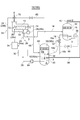
- the oil supply system 10 includes an oil tank 20 for receiving the oil o accumulated in the lower part of the oil separator 16 and an oil pipe 18 connected to the oil separator 16 and the oil tank 20, and the oil pipe 18 has a pressure reducing valve. 22 and a stirrer 36 (36a, 36b) are provided. Further, the oil supply systems 24 and 26 for supplying the oil o from which the compressed gas g is separated to the compressor 12, and the oil supply pipe 28 for supplying the oil o accumulated at the bottom of the oil tank 20 to the oil supply systems 24 and 26. And have.
- the oil separator 16 and the oil tank 20 are provided with internal spaces, and demisters 30 and 62 are provided in these internal spaces.
- the compressed gas g separated from the oil o is removed from the liquid content such as the oil o by the demister 30, and is supplied to the application destination via the pipe 15.
- the compressed gas g separated from the oil o is returned to the compressor 12 after the liquid content such as the oil o is removed by the demister 62.
- the gas is returned to the suction side gas supply path 70 of the compressor 12 via the gas pipe 60.
- the oil supply pipe 28 is provided with an oil cooler 32 and an oil filter 34 on the downstream side of the oil cooler 32.
- the oil o sent from the oil tank 20 to the compressor 12 via the oil supply pipe 28 is cooled by the oil cooler 32, if necessary, and then the impurities are removed by the oil filter 34.
- the refueling pipe 28 communicates with the refueling system 24 that supplies the oil o to the compression space Sc, and the other refueling system 26.
- the refueling system 24 is connected to, for example, a refueling system 24 (24a) that supplies oil o into the compressed gas g in the compression process of the compressor 12, or a gas supply path 70 on the suction side of the compressed gas g, and the amount of refueling is increased.
- a refueling system 24 (24b) is provided for replenishment when there is a shortage.
- the refueling system 26 is, for example, a refueling system for refueling a seal portion such as a bearing of the compressor 12 or a mechanical seal.
- the compressor 12 is applied to a refrigeration system that constitutes a refrigeration cycle or a heat pump system that constitutes a heat pump cycle capable of supplying cold and hot heat to an application destination.
- the compressor 12 is provided in the refrigerant circulation path, and in the embodiments shown in FIGS. 1 and 2, the compressed gas g corresponds to the refrigerant, and the discharge pipe 14 and the pipe 15 circulate the refrigerant. It forms part of the road.
- the compressed gas g dissolved in the oil o is degassed from the oil o while the oil o falls into the oil sump. Therefore, the amount of dissolved gas g to be compressed contained in the oil o accumulated in the oil pool of the oil tank 20 can be reduced.
- the oil pipe 18 is not provided with a temperature adjusting device for heating or cooling the oil o flowing through the oil pipe 18. Therefore, the equipment cost of the oil supply system 10 can be reduced.
- the oil supply system 10 does not require a device for cooling the oil o because the latent heat of vaporization is taken from the oil and the oil o is cooled when the compressed gas g dissolved in the oil o evaporates. Further, the solubility of the compressed gas can be lowered by raising the temperature of the oil o, whereby the degassing of the compressed gas g dissolved in the oil o can be promoted.
- the pressure reducing valve 22 Since the synergistic effect of the depressurization of the oil o and the stirring action of the oil o by the stirrer 36 can promote the degassing of the compressed gas g dissolved in the oil o, a heating device for raising the temperature of the oil o is required. Do not.
- the stirrer 36 (36b) is composed of a turbulator (turbulent device) 40 provided inside the oil pipe 18.
- a stirrer can be configured by providing the turbulator 40 at an appropriate position in the axial direction of the oil pipe 18.
- the oil o forms a turbulent flow while flowing through the turbulator 40 and is agitated, causing a pressure loss in the oil o. Thereby, the degassing of the compressed gas g dissolved in the oil o can be promoted.
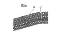
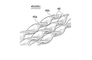
- FIG. 3 to 5 are perspective views showing some embodiments of the turbulator 40.
- the turbulator 40 (40a) shown in FIG. 3 is composed of a rod-shaped core 42 and a large number of loops 44 arranged around the core 42 and formed in a ring shape such as a circle or an ellipse.
- a large number of loops 44 formed around the core 42 cause the oil o flowing through the oil pipe 18 to hit the loops 44 to form a turbulent flow and be agitated, causing a pressure loss.
- the large number of loops 44 formed around the core 42 can enhance the stirring effect of the oil o and promote the vaporization of the compressed gas g dissolved in the oil o.
- the turbulator 40 (40b) shown in FIG. 4 is composed of, for example, a plurality of bar-shaped bars 46 having a rectangular cross section (rectangular in the exemplary embodiment shown in FIG. 4), and each bar 46 has an axis. A pair of surfaces 46a and 46b that are twisted along the direction and face each other are spirally bent. As a result, each bar 46 is configured so that the surface thereof forms irregularities. These plurality of bars 46 are inserted in parallel inside the oil pipe 18 along the axial direction of the oil pipe 18. Since the surface of each bar 46 has a spiral unevenness, the oil o flowing through the oil pipe 18 hits the bar 46 and is agitated by forming a turbulent flow, whereby the oil o causes a pressure loss. In this way, the stirring effect of the oil o can be enhanced, and the speed at which the gas-dissolving component dissolved in the oil o vaporizes and separates from the oil can be increased.
- the turbulator 40 (40c) shown in FIG. 5 is formed into a rod-shaped core 48 and a ring shape (an oval shape in the exemplary embodiment shown in FIG. 5) arranged around the core 48 and having a circular shape, an elliptical shape, or the like. It is composed of a large number of loops 50.
- the turbulator 40 (40c) By arranging the turbulator 40 (40c) inside the oil pipe 18 along the axial direction of the oil pipe 18, the oil o flowing through the oil pipe 18 hits a large number of loops 50 to form a turbulent flow and is agitated. ..
- the oil o causes a pressure loss and the stirring effect of the oil o can be enhanced, so that the speed at which the gas-dissolving component dissolved in the oil o is degassed and separated from the oil can be increased.
- the core 42 is made of a flexible material and can be freely bent according to the axial bending of the oil pipe 18. It becomes easy to insert it inside the oil pipe 18.
- the turbulent flow forming action can be enhanced.
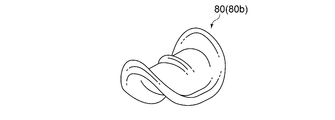
- the irregular filling 80 (80a, 80b, 80c) shown in FIGS. 6A to 6B is arranged in the oil pipe 18.
- the irregular filling 80 is, for example, the Raschig ring 80 (80a) shown in FIG. 6A, the Beruru saddle 80 (80b) shown in FIG. 6B, the pole ring 80 (80c), and the like.
- a large number of these irregular fillings are arranged so as to block the cross section of the oil pipe 18.
- the oil o flowing through the flow path in which the irregular filling 80 is arranged forms a turbulent flow and is agitated to cause a pressure loss, thereby further degassing the compressed gas g dissolved in the oil o. Can be promoted.
- the irregular filling 80 may be arranged so as to block the entire cross section of the oil pipe 18, or may be arranged so as to block a part of the cross section. May be good. Further, the irregular filling 80 may be arranged at the same place as the turbulator 40, or may be arranged at a different place in the axial direction of the oil pipe 18. By arranging the irregular filling 80 at the place where the turbulator 40 is arranged, the turbulent flow forming effect can be enhanced and the stirring effect can be enhanced.
- the stirrer 36 (36a) is composed of a meandering flow path portion 52 formed in the flow path of the oil pipe 18.
- the oil o flowing through the meandering flow path portion 52 meanders, causing pressure loss and forming a turbulent flow.
- the stirring effect of the oil o can be enhanced, and the degassing of the gas-dissolving component can be promoted.
- the meandering flow path portion 52 intersects the axial direction of the oil pipe 18 (in the exemplary embodiment shown in FIG. 7, the direction perpendicular to the axial direction of the oil pipe 18). It is composed of a large number of baffle plates 54 arranged in parallel with each other. A large number of baffle plates 54 are arranged in parallel at intervals along the axial direction of the oil pipe 18, and every other baffle plate 54 is arranged so as to be displaced in the radial direction of the oil pipe 18, so that the meandering flow path Fm Is formed. Pressure loss occurs when the oil o flows through the meandering flow path Fm. As a result, the speed at which the gas-dissolved component dissolved in the oil o is vaporized and separated from the oil o can be increased.
- the portion of the oil pipe 18 where the stirrer 36 (36a) is provided is a pipe whose diameter is larger than that of the other oil pipe 18, and a turbulator 40 is built in this pipe or a meandering flow path portion 52 is provided. You may. Further, as another embodiment, the portion of the oil pipe 18 provided with the stirrer 36 (36b) may be formed of a pipe having the same diameter as the other oil pipe 18. Further, the irregular filling 80 may be filled in the meandering flow path Fm formed in the meandering flow path portion 52. Thereby, the turbulent flow forming effect of the oil o flowing through the meandering flow path Fm can be enhanced, and the stirring effect can be enhanced.
- the stirrer 36 (36b) has a jet spray nozzle 38 provided in the oil pipe 18 and open to the oil tank 20.
- the oil o flowing through the oil pipe 18 is sprayed from the jet spray nozzle 38 into the gas phase portion Sg of the oil tank 20 in the form of mist.
- the jet spray nozzle 38 is connected to the outlet of the oil pipe 18 inside the oil tank 20.
- the nozzle port of the jet spray nozzle 38 that opens inside the oil tank 20 is oriented in the horizontal direction or at an angle close to the horizontal direction. As a result, it is possible to prolong the time for the oil o sprayed from the jet spray nozzle 38 to reach the oil sump accumulated in the lower part of the oil tank 20. This can promote the vaporization of the gas-dissolved component of the gas to be compressed g from the sprayed oil o. By pointing the nozzle port of the jet spray nozzle 38 diagonally upward, the time to reach the oil sump can be further extended. As a result, it is possible to further promote the vaporization of the gas-dissolved component of the gas to be compressed g from the sprayed oil o.
- a gas pipe 60 for connecting the gas phase portion Sg of the oil tank 20 and the suction side space of the compressor 12 is provided. Since the gas pipe 60 is provided, the gas to be compressed g separated into the gas phase portion Sg of the oil tank 20 can be supplied to the suction side space of the compressor 12, and the gas phase portion Sg has the same pressure as the suction side space of the compressor 12. Therefore, the gas-dissolving component contained in the oil o flowing out from the oil pipe 18 to the oil tank 20 can be vaporized in the gas phase portion Sg under reduced pressure and separated from the oil o.
- the oil supply system 10 (10B) shown in FIG. 2 it is possible to promote the vaporization of the gas-dissolved component of the compressed gas g from the mist-like oil o sprayed from the jet spray nozzle 38 onto the gas phase portion Sg.
- the gas pipe 60 is connected to the suction side gas supply path 70 communicating with the suction port of the compressor 12 on the compressor 12 side, and the gas phase portion Sg of the oil tank 20 is compressed.
- the gas g is returned to the suction side gas supply path 70.
- the oil tank 20 is composed of a container that is long in the vertical direction, and a gas pipe 60 is connected to the top of the container.
- a demister 62 is provided below the top to which the gas pipe 60 is connected. Since the demister 62 captures the liquid such as oil, it is possible to prevent the liquid from entering the compression space Sc of the compressor 12 through the gas pipe 60.
- the oil supply pipe 28 that supplies oil o to the oil supply systems 24 and 26 that supply oil o to the compressor 12 includes an oil pump 64. Since the oil supply pipe 28 includes an oil pump 64, oil o is not hindered from the low pressure oil tank 20 to the compression space Sc of the compressor 12 having a pressure higher than that of the oil tank 20 and the oil supply portion of the compressor 12 including the bearing portion. Can be supplied.
- the oil supply pipe 28 supplies oil o to the oil supply system 24 that supplies oil o to the compression space Sc on the downstream side, and to the bearings, seals, and the like of the compressor 12. It branches to the refueling system 26.
- a defoaming device 82 for suppressing bubbles generated on the surface of the oil o accumulated in the lower part of the oil tank 20 is provided.
- the bubbling generated on the surface of the oil sump formed in the lower part of the oil tank 20 can be eliminated, and by removing the bubbles on the surface of the oil sump, the compressed gas g from the surface of the oil sump can be eliminated. Can promote defoaming. Further, the liquid level of the oil o accumulated in the oil tank 20 can be controlled without any trouble.
- FIG. 8 is a front view of the defoaming device 82 (82a) according to the embodiment, and is a view showing the oil tank 20 cut off.
- one of the compressed gas g that is connected to the nozzle body 84 provided in the upper center portion of the oil sump surface inside the oil tank 20 and the pipe 15 and the nozzle body 84 and flows through the pipe 15. It is provided with a pipe 86 that branches the portion and supplies the nozzle body 84.
- the nozzle body 84 is provided with a tubular casing, has a spray cylinder 88 having a diameter larger than that of the casing at the lower part of the casing, and spray holes 88a are formed on the outer peripheral surface of the spray cylinder 88 on the entire peripheral surface.
- the cross section of the nozzle body 84 and the spray hole 88a may be circular, elliptical or square.
- the nozzle body 84 is supported by a support member 85 at the center of the inside of the oil tank 20 above the surface of the oil sump.
- a part of the compressed gas g flowing through the pipe 15 is introduced into the nozzle body 84 via the pipe 86.
- the compressed gas g introduced into the nozzle body 84 is sprayed horizontally from the spray hole 88a to the outside in the radial direction of the spray cylinder 88.
- the compressed gas g sprayed from the spray hole 88a forms a circulating flow Fcg that goes downward from the inner wall surface of the oil tank 20 and further toward the center side in the oil tank 20.
- the bubbles f generated on the surface of the oil sump by the circulating flow Fcg are collected toward the center side in the oil tank 20 and disappear by the compressed gas g injected from the spray hole 88a formed on the bottom surface of the spray cylinder 88.
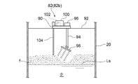
- the ultrasonic oscillator 98 is arranged so as to be oblique with respect to the vertical direction, and the rotation of the rotating shaft 94 makes it possible to oscillate ultrasonic waves in a wide range from the ultrasonic oscillator 98 with respect to the bubble f. ..
- the angle of the ultrasonic oscillator 98 with respect to the vertical direction is adjustable, and by adjusting the angle of the ultrasonic oscillator 98 with respect to the vertical direction, the range in which ultrasonic waves can be applied to the bubble f can be adjusted. It is configured.
- a controller 102 is provided inside the casing 100 fixed to the base 90, and a rod-shaped bubble sensor 104 hangs vertically from the base 90.
- the bubble sensor 104 detects the bubble f, and the detection signal is sent to the controller 102.
- the controller 102 operates the ultrasonic oscillator 98 to oscillate ultrasonic waves from the ultrasonic oscillator 98 toward the bubble f. In this way, the bubble f can be extinguished by oscillating the ultrasonic wave toward the bubble f.
- the defoaming device 82 (82b)
- the foam sensor 104 detects it and automatically operates to extinguish the foam f.
- the heater 110 is composed of a heat transfer wire, and the conductor 116 is connected to the heat transfer wire, and the heater 110 is configured after passing through the conductor 116 from a power source (not shown).
- the heater 110 is heated by energizing the heat transfer wire.
- the bubbles f generated on the surface Ls of the oil pool disappear when heated by the heater 110.
- FIG. 11 is a perspective view showing a part of the oil tank 20 provided with the defoaming device 82 (82d) according to still another embodiment by cutting.
- the defoaming device 82 (82d) includes a nozzle 120 arranged inside the oil tank 20, and a pipe 86 connected to the pipe 15 and the nozzle 120.
- the compressed gas g is supplied to the nozzle 120 via the pipe 86.
- the nozzle 120 is arranged above the surface Ls of the oil sump and near the wall surface of the oil tank 20.
- the nozzle port of the nozzle 120 is arranged toward the surface Ls of the oil sump formed below, and is arranged diagonally in the circumferential direction of the oil tank 20 instead of in the vertical direction.
- the circulating flow Fco of the oil o is formed on the surface Ls of the oil pool by the force of the compressed gas g injected from the nozzle 120.
- the bubbles f generated above the surface Ls also circulate in the same direction as the circulating flow Fco.
- the bubbles f are sequentially moved to the positions where they hit the compressed gas g blown out from the nozzle 120, so that the bubbles f are sequentially blown off by the compressed gas g blown out from the nozzle 120 and disappear.
- the pipe portion from the pressure reducing valve 22 to the connection end with the oil tank 20 is inclined downward toward the horizontal or downstream side.
- reference numeral 18a is attached to the upstream piping portion from the oil separator 16 to the pressure reducing valve 22 of the oil piping 18, and reference numeral 18b is attached to the downstream piping portion from the pressure reducing valve 22 to the connection end with the oil tank 20. It is attached.
- the downstream piping portion 18b according to the present embodiment is represented by a chain double-dashed line and is designated by reference numeral 18b'.
- the downstream side piping portion 18b' is arranged horizontally or inclined downward toward the downstream side, the amount of decompression by the pressure reducing valve 22 due to the oil o flowing through the downstream side piping portion 18b' There is no head difference that cancels out. Therefore, even if the amount of decompression by the pressure reducing valve 22 is increased, the oil flow toward the oil tank 20 can be secured inside the downstream piping portion 18b'. That is, unlike the U-shaped bend, the compressed gas g is not trapped. As a result, it is possible to prevent the decompressed gas g degassed from the oil o from staying in the downstream piping portion 18b', so that the degassed compressed gas g stays in the downstream piping portion 18b' while the oil is staying.
- the residence time of the oil o can be lengthened in the downstream piping portion 18b', so that the dissolved gas is removed from the downstream piping portion 18b'. You can secure time.
- the downstream piping portion 18b is configured to have a larger flow path cross-sectional area than the upstream piping portion 18a. According to this embodiment, since the decompression space decompressed by the decompression valve 22 can be increased in the oil pipe, the residence time of the oil o in the decompression space can be lengthened, thereby being compressed from the oil o. The degassing of gas g can be further promoted.
- the downstream piping portion 18b is configured to be longer than half of the total length of the oil piping 18. According to this embodiment, since the decompression space decompressed by the decompression valve 22 can be increased in the oil pipe, the residence time of the oil o in the decompression space can be lengthened, thereby decompressing the compressed gas g. You can further promote your qi.
- the oil supply system (10) of the compressor includes an oil separator (16) connected to the discharge pipe (14) of the compressor (12) and oil from an oil pool of the oil separator (16).
- the oil tank (20) for receiving (o), the oil pipe (18) provided between the oil separator (16) and the oil tank (20), and the oil pipe (18) are provided.
- the pressure reducing valve (22) and the oil supply pipe (24, 26) for supplying the oil to the compressor (12) from the oil pool of the oil tank (20). 28) and a stirrer (36) provided in the oil pipe (18).
- oil having a small amount of gas-dissolving components and not having a low viscosity can be supplied from the oil tank to the compressor, so that the lubrication function and the sealing function can be ensured especially in the bearing and the sealing portion of the compressor.
- the residence time of the oil in the oil tank is relatively short, or even if the volume of the oil tank is small, the separation of the oil and the compressed gas can be achieved with high efficiency, so that the operation of the oil supply system can be achieved. The efficiency can be improved and the oil tank can be downsized.
- the oil decompressed through the decompression valve is agitated by the stirrer, so that the degassing of the compressed gas dissolved in the oil can be promoted.
- the oil and the decompressed gas degassed from the oil flow out from the outlet of the oil pipe to the gas phase portion of the oil tank, so that the decompressed gas degassed from the oil is accumulated in the oil of the oil tank. It can be prevented from being mixed with the oil and dissolving again. Further, the degassing from the oil is promoted when the gas-dissolved component that has not been degassed from the oil is also released into the gas phase portion.
- the compressor oil supply system (10) is the compressor oil supply system according to any one of 1) to 3), and the oil pipe (18) is the oil. It is not provided with a temperature control device for heating or cooling the oil (o) flowing through the pipe (18).
- the oil supply system of the compressor according to the above embodiment does not require a device for cooling the oil in the oil pipe because it takes away latent heat of evaporation and cools the oil when the gas to be compressed dissolved in the oil vaporizes. Further, the oil supply system of the compressor according to the above embodiment raises the temperature of the oil to be compressed in order to promote the degassing of the compressed gas dissolved in the oil by the pressure reducing valve and the stirrer provided in the oil pipe. By lowering the solubility of the gas, no heating device is required to promote the degassing of the dissolved gas to be compressed.
- the compressor oil supply system (10) is the compressor oil supply system according to any one of 1) to 4), and the stirrer (36) is the oil. Includes a turbulator (40) provided inside the pipe (18).
- the compressor oil supply system (10) is the compressor oil supply system according to any one of 1) to 4), and the stirrer (36) is the oil.
- the meandering flow path portion (52) formed in the flow path of the pipe (18) is included.
- degassing of the compressed gas dissolved in the oil can be promoted by agitating the oil flowing in the meandering flow path portion by causing a turbulent flow and causing a pressure loss.
- the compressor oil supply system (10) is the compressor oil supply system according to 3), and the stirrer (36) is provided in the oil pipe (18). It includes a spray nozzle (38) that opens into the gas phase portion (Sg) of the oil tank (20).
- the oil flowing into the oil tank from the oil pipe is sprayed in a mist form from the spray nozzle to the gas phase portion of the oil tank, so that the degassing of the compressed gas dissolved in the oil can be promoted.
- the compressor oil supply system (10) is the compressor oil supply system according to any one of 1) to 7), and is stored in the oil separator (16).
- a liquid level sensor (56) that detects the liquid level of the oil (o)
- a control unit (58) that controls the opening degree of the pressure reducing valve (22) based on the detected value of the liquid level sensor (56). , Equipped with.
- the compressor oil supply system (10) is the compressor oil supply system according to any one of 1) to 8), and the gas phase portion of the oil tank (20).
- a gas pipe (60) for connecting (Sg) and the suction side space of the compressor (12) is provided.
- the compressor oil supply system (10) is the compressor oil supply system according to any one of 1) to 9), and the oil supply pipe (28) is an oil pump. (64) is provided.
- oil can be supplied from the oil tank having a low pressure atmosphere to the compression space of the compressor having a pressure higher than that of the oil tank and the oil supply portion of the compressor including the bearing portion without any trouble. ..
- the compressor oil supply system (10) is the compressor oil supply system according to any one of 1) to 10), wherein the compressor (12) is a screw compressor.
- the refueling system (24, 26) includes at least a refueling system (26) that supplies the oil to the bearings of the screw rotors (72, 74) constituting the screw compressor.
- the compressor oil supply system (10) is the compressor oil supply system according to any one of 1) to 11), and is accumulated inside the oil tank (20).
- a defoaming device (82) for suppressing bubbles (f) generated on the surface of the oil (o) is provided.
- the bubbling generated on the surface of the oil sump in the oil tank can be eliminated, and the degassing of the compressed gas from the surface of the oil sump can be promoted by removing the bubbles on the surface of the oil sump. Further, the liquid level of the oil accumulated in the oil tank can be controlled without any trouble.
- the compressor oil supply system (10) is the compressor oil supply system according to any one of 1) to 12), and the oil pipe (18) is the decompression.
- the piping portion (18b') from the valve (22) to the connection end with the oil tank (20) is inclined downward toward the horizontal or downstream side.
- the compressor oil supply system (10) according to still another aspect is the compressor oil supply system according to any one of 1) to 13), and the oil pipe (18) is the decompression.
- the downstream portion (18b) of the valve (22) has a larger flow path cross-sectional area than the upstream portion (18a) of the pressure reducing valve (22).
- the decompression space decompressed by the decompression valve can be increased in the oil pipe, so that the residence time of the oil in the decompression space can be lengthened, whereby the compressed gas from the oil can be increased. Can promote degassing.
- the compressor oil supply system (10) according to still another aspect is the compressor oil supply system according to any one of 1) to 14), and the depressurization of the oil pipe (18).
- the portion (18b) on the downstream side of the valve (22) is longer than half of the total length of the oil pipe (18).
Landscapes
- Engineering & Computer Science (AREA)
- Mechanical Engineering (AREA)
- General Engineering & Computer Science (AREA)
- Physics & Mathematics (AREA)
- Thermal Sciences (AREA)
- Chemical & Material Sciences (AREA)
- Analytical Chemistry (AREA)
- Power Engineering (AREA)
- Applications Or Details Of Rotary Compressors (AREA)
- Compressor (AREA)
- Degasification And Air Bubble Elimination (AREA)
Abstract
Description
例えば、「ある方向に」、「ある方向に沿って」、「平行」、「直交」、「中心」、「同心」或いは「同軸」等の相対的或いは絶対的な配置を表す表現は、厳密にそのような配置を表すのみならず、公差、若しくは、同じ機能が得られる程度の角度や距離をもって相対的に変位している状態も表すものとする。
また例えば、四角形状や円筒形状等の形状を表す表現は、幾何学的に厳密な意味での四角形状や円筒形状等の形状を表すのみならず、同じ効果が得られる範囲で、凹凸部や面取り部等を含む形状も表すものとする。
一方、一の構成要素を「備える」、「具える」、「具備する」、「含む」、又は、「有する」という表現は、他の構成要素の存在を除外する排他的な表現ではない。
また、蛇行流路部52に形成される蛇行流路Fmに不規則充填物80を充填してもよい。これによって、蛇行流路Fmを流れる油oの乱流形成効果を高め、撹拌効果を高めることができる。
図2に示す例示的な実施形態では、ジェットスプレノズル38はオイルタンク20の内部において油配管18の出口に接続されている。
なお、ジェットスプレノズル38のノズル口を上方へ斜めに向けることで、油溜まりに到達する時間をさらに長くすることができる。これによって、噴霧された油oから被圧縮ガスgのガス溶解成分が気化するのをさらに促進できる。
12 圧縮機
14 吐出配管
15、86 配管
16 オイルセパレータ
18 油配管
18a 上流側配管部分
18b、18b’ 下流側配管部分
20 オイルタンク
22 減圧バルブ
24(24a、24b)、26(26a、26b) 給油系統
28 給油配管
30、62 デミスタ
32 オイルクーラ
34 オイルフィルタ
36(36a、36b) 撹拌器
38 ジェットスプレノズル
40(40a、40b、40c) タービュレータ
42、48 芯
44、50 ループ
46 バー
52 蛇行流路部
54 バッフルプレート
56 液面センサ
58、102 コントローラ
60 ガス配管
64 油ポンプ
66 返油管
70 吸入側ガス供給路
72、74 スクリュロータ
80(80a、80b、80c) 不規則充填物
80a ラシヒリング
80b ベルルサドル
80c ポールリング
82(82a、82b、82c、82d) 消泡装置
84 ノズル本体
85、92 支持部材
88 噴霧筒
88a 噴霧孔
90、112 基部
94 回転軸
96 駆動部
98 超音波発振器
100、114 ケーシング
104 泡センサ
110 ヒータ
113 フランジ部
116 導線
120 ノズル
Fcg、Fco 循環流
Fm 蛇行流路
Ls 油溜まり表面
Sc 圧縮空間
Sg 気相部
f 泡
g 被圧縮ガス
o 油
Claims (15)
- 圧縮機の吐出配管に接続されるオイルセパレータと、
前記オイルセパレータの油溜まりから油を受け入れるためのオイルタンクと、
前記オイルセパレータと前記オイルタンクとの間に設けられた油配管と、
前記油配管に設けられた減圧バルブと、
前記オイルタンクの油溜まりから前記圧縮機に前記油を供給するための給油系統に前記油を供給する給油配管と、
前記油配管に設けられた撹拌器と、
を備える圧縮機の油供給システム。 - 前記撹拌器は、前記減圧バルブより下流側で前記油配管に設けられた請求項1に記載の圧縮機の油供給システム。
- 前記油配管は前記オイルタンクの気相部に接続されている請求項1又は2に記載の圧縮機の油供給システム。
- 前記油配管は、前記油配管を流れる前記油を加熱又は冷却するための温度調整装置を備えていない請求項1乃至3の何れか一項に記載の圧縮機の油供給システム。
- 前記撹拌器は、前記油配管の内部に設けられたタービュレータを含む請求項1乃至4の何れか一項に記載の圧縮機の油供給システム。
- 前記撹拌器は、前記油配管の流路に形成された蛇行流路部を含む請求項1乃至4の何れか一項に記載の圧縮機の油供給システム。
- 前記撹拌器は、前記油配管に設けられ前記オイルタンクの気相部に開口するスプレノズルを含む請求項3に記載の圧縮機の油供給システム。
- 前記オイルセパレータに貯留された前記油の液面を検出する液面センサと、
前記液面センサの検出値に基づいて前記減圧バルブの開度を制御する制御部と、
を備える請求項1乃至7の何れか一項に記載の圧縮機の油供給システム。 - 前記オイルタンクの気相部と前記圧縮機の吸入側空間とを接続するガス配管を備える請求項1乃至8の何れか一項に記載の圧縮機の油供給システム。
- 前記給油配管は油ポンプを備える請求項1乃至9の何れか一項に記載の圧縮機の油供給システム。
- 前記圧縮機はスクリュ圧縮機で構成され、
前記給油系統は、少なくとも前記スクリュ圧縮機を構成するスクリュロータの軸受に前記油を供給する給油系統を含む請求項1乃至10の何れか一項に記載の圧縮機の油供給システム。 - 前記オイルタンクの内部に溜まった前記油の表面に発生する泡を抑えるための消泡装置を備える請求項1乃至11の何れか一項に記載の圧縮機の油供給システム。
- 前記油配管は、前記減圧バルブから前記オイルタンクとの接続端までの配管部分が、水平又は下流側に向かって下方に傾斜している請求項1乃至12の何れか一項に記載の圧縮機の油供給システム。
- 前記油配管は、前記減圧バルブの下流側の部位が、前記減圧バルブの上流側の部位よりも流路断面積が大きい請求項1乃至13の何れか一項に記載の圧縮機の油供給システム。
- 前記油配管のうち前記減圧バルブの下流側の部位が、前記油配管の全長の半分よりも長い請求項1乃至14の何れか一項に記載の圧縮機の油供給システム。
Priority Applications (4)
| Application Number | Priority Date | Filing Date | Title |
|---|---|---|---|
| JP2021561477A JP7316375B2 (ja) | 2019-11-28 | 2020-11-26 | 圧縮機の油供給システム |
| BR112022008524-9A BR112022008524B1 (pt) | 2019-11-28 | 2020-11-26 | Sistema de suprimento de óleo para compressor |
| US17/774,890 US12025356B2 (en) | 2019-11-28 | 2020-11-26 | Oil supply system for compressor |
| SA522432678A SA522432678B1 (ar) | 2019-11-28 | 2022-05-22 | نظام الإمداد بالزيت لضاغط |
Applications Claiming Priority (2)
| Application Number | Priority Date | Filing Date | Title |
|---|---|---|---|
| JPPCT/JP2019/046580 | 2019-11-28 | ||
| PCT/JP2019/046580 WO2021106145A1 (ja) | 2019-11-28 | 2019-11-28 | 圧縮機の油供給システム |
Publications (1)
| Publication Number | Publication Date |
|---|---|
| WO2021106989A1 true WO2021106989A1 (ja) | 2021-06-03 |
Family
ID=76130411
Family Applications (2)
| Application Number | Title | Priority Date | Filing Date |
|---|---|---|---|
| PCT/JP2019/046580 Ceased WO2021106145A1 (ja) | 2019-11-28 | 2019-11-28 | 圧縮機の油供給システム |
| PCT/JP2020/043970 Ceased WO2021106989A1 (ja) | 2019-11-28 | 2020-11-26 | 圧縮機の油供給システム |
Family Applications Before (1)
| Application Number | Title | Priority Date | Filing Date |
|---|---|---|---|
| PCT/JP2019/046580 Ceased WO2021106145A1 (ja) | 2019-11-28 | 2019-11-28 | 圧縮機の油供給システム |
Country Status (4)
| Country | Link |
|---|---|
| US (1) | US12025356B2 (ja) |
| JP (1) | JP7316375B2 (ja) |
| SA (1) | SA522432678B1 (ja) |
| WO (2) | WO2021106145A1 (ja) |
Cited By (1)
| Publication number | Priority date | Publication date | Assignee | Title |
|---|---|---|---|---|
| US20230213040A1 (en) * | 2021-12-30 | 2023-07-06 | Trane International Inc. | Compressor lubrication supply system and compressor thereof |
Families Citing this family (4)
| Publication number | Priority date | Publication date | Assignee | Title |
|---|---|---|---|---|
| US11215182B2 (en) * | 2018-03-01 | 2022-01-04 | Ingersoll-Rand Industrial U.S., Inc. | Multi-stage compressor having interstage lubricant injection via an injection rod |
| CN117190518A (zh) * | 2022-05-31 | 2023-12-08 | 开利公司 | 制冷系统 |
| CN117006757A (zh) * | 2023-09-13 | 2023-11-07 | 珠海格力电器股份有限公司 | 分离储油器、空调系统及空调系统供油方法 |
| CN120403127A (zh) * | 2024-01-31 | 2025-08-01 | 开利公司 | 制冷系统 |
Citations (4)
| Publication number | Priority date | Publication date | Assignee | Title |
|---|---|---|---|---|
| JPS5228714A (en) * | 1975-08-29 | 1977-03-03 | Shimizu Constr Co Ltd | Erection process for underground strage equipment |
| JPS5313653A (en) * | 1976-07-23 | 1978-02-07 | Mitsubishi Heavy Ind Ltd | Method of coating high-viscosity material and equipment therefor |
| JP2003286982A (ja) * | 2002-03-26 | 2003-10-10 | Sanyo Electric Co Ltd | ロータリコンプレッサ |
| JP2016161211A (ja) * | 2015-03-02 | 2016-09-05 | ダイキン工業株式会社 | 冷凍装置 |
Family Cites Families (9)
| Publication number | Priority date | Publication date | Assignee | Title |
|---|---|---|---|---|
| US2760936A (en) * | 1952-05-20 | 1956-08-28 | Nat Cylinder Gas Co | Manufacture of lithium grease |
| JPS5228714U (ja) | 1975-08-22 | 1977-02-28 | ||
| JPS563575Y2 (ja) | 1976-07-17 | 1981-01-26 | ||
| EP0758054B1 (de) * | 1995-08-09 | 2001-03-07 | SULZER-ESCHER WYSS GmbH | Schmiersystem für Schraubenverdichtern |
| JP4268251B2 (ja) | 1998-12-24 | 2009-05-27 | 株式会社神戸製鋼所 | 油冷式スクリュ圧縮機 |
| WO2006013636A1 (ja) | 2004-08-03 | 2006-02-09 | Mayekawa Mfg.Co.,Ltd. | 多系統潤滑式スクリュー圧縮機の潤滑油供給システム及び運転方法 |
| JP4365442B1 (ja) * | 2008-05-29 | 2009-11-18 | 株式会社神戸製鋼所 | 石炭の改質方法 |
| KR101454476B1 (ko) * | 2013-01-25 | 2014-10-28 | 삼성중공업 주식회사 | 유증기 회수 장치 및 이를 포함하는 선박 |
| US10662947B2 (en) * | 2015-02-12 | 2020-05-26 | Mayekawa Mfg. Co., Ltd. | Oil-flooded screw compressor system and method for modifying the same |
-
2019
- 2019-11-28 WO PCT/JP2019/046580 patent/WO2021106145A1/ja not_active Ceased
-
2020
- 2020-11-26 JP JP2021561477A patent/JP7316375B2/ja active Active
- 2020-11-26 US US17/774,890 patent/US12025356B2/en active Active
- 2020-11-26 WO PCT/JP2020/043970 patent/WO2021106989A1/ja not_active Ceased
-
2022
- 2022-05-22 SA SA522432678A patent/SA522432678B1/ar unknown
Patent Citations (4)
| Publication number | Priority date | Publication date | Assignee | Title |
|---|---|---|---|---|
| JPS5228714A (en) * | 1975-08-29 | 1977-03-03 | Shimizu Constr Co Ltd | Erection process for underground strage equipment |
| JPS5313653A (en) * | 1976-07-23 | 1978-02-07 | Mitsubishi Heavy Ind Ltd | Method of coating high-viscosity material and equipment therefor |
| JP2003286982A (ja) * | 2002-03-26 | 2003-10-10 | Sanyo Electric Co Ltd | ロータリコンプレッサ |
| JP2016161211A (ja) * | 2015-03-02 | 2016-09-05 | ダイキン工業株式会社 | 冷凍装置 |
Cited By (4)
| Publication number | Priority date | Publication date | Assignee | Title |
|---|---|---|---|---|
| US20230213040A1 (en) * | 2021-12-30 | 2023-07-06 | Trane International Inc. | Compressor lubrication supply system and compressor thereof |
| US11898571B2 (en) * | 2021-12-30 | 2024-02-13 | Trane International Inc. | Compressor lubrication supply system and compressor thereof |
| US20240183360A1 (en) * | 2021-12-30 | 2024-06-06 | Trane International Inc. | Compressor lubrication supply system and compressor thereof |
| US12209592B2 (en) * | 2021-12-30 | 2025-01-28 | Trane International Inc. | Compressor lubrication supply system and compressor thereof |
Also Published As
| Publication number | Publication date |
|---|---|
| BR112022008524A2 (pt) | 2022-09-20 |
| JP7316375B2 (ja) | 2023-07-27 |
| US12025356B2 (en) | 2024-07-02 |
| WO2021106145A1 (ja) | 2021-06-03 |
| JPWO2021106989A1 (ja) | 2021-06-03 |
| SA522432678B1 (ar) | 2024-07-01 |
| US20220390157A1 (en) | 2022-12-08 |
Similar Documents
| Publication | Publication Date | Title |
|---|---|---|
| JP7316375B2 (ja) | 圧縮機の油供給システム | |
| US9828997B2 (en) | Scroll compressor with a resonator | |
| JP3943542B2 (ja) | フローイングプールシェル及び管状エバポレータ | |
| CN104145167B (zh) | 离心式制冷剂蒸气压缩机 | |
| US8187370B2 (en) | Horizontal bulk oil separator | |
| EP2860401B1 (en) | Compressor system with thermally active heat exchanger | |
| EP2664386B1 (en) | A centrifugal separator | |
| CN103958996B (zh) | Hvac系统中的制冷剂处理 | |
| KR101465868B1 (ko) | 로터리식 압축기 | |
| WO2017061167A1 (ja) | 多段圧縮機およびこれを備えた冷凍システム | |
| RU2752504C2 (ru) | Способ и устройство для нагрева и очистки жидкостей | |
| JP6799792B2 (ja) | 流体機械及び冷凍サイクル装置 | |
| CN107218217A (zh) | 用于多压缩机系统的吸入管线布置 | |
| KR102189168B1 (ko) | 압축기 조립체 및 그 제어 방법 그리고 냉각/가열 시스템 | |
| US20180252233A1 (en) | Turbo compressor and turbo chilling apparatus equipped with the turbo compressor | |
| WO2019033894A1 (zh) | 旋转机械 | |
| CN108779946A (zh) | 制冷机 | |
| JP5271928B2 (ja) | 循環ポンプ | |
| CN104079108A (zh) | 涡轮制冷机的压缩机用电动机 | |
| CN106286226A (zh) | 一种压缩机的油泵及变频压缩机 | |
| US11415022B2 (en) | Oil console equipment, rotary machine provided with oil console equipment, and method for recovering lubrication oil contained in exhaust gas | |
| BR112022008524B1 (pt) | Sistema de suprimento de óleo para compressor | |
| CN111373213A (zh) | 两级油动力喷射器系统 | |
| JP5261233B2 (ja) | 潤滑装置 | |
| EP1185346B1 (en) | An apparatus for rectification of liquid mixtures and/or for scrubbing of gases |
Legal Events
| Date | Code | Title | Description |
|---|---|---|---|
| 121 | Ep: the epo has been informed by wipo that ep was designated in this application |
Ref document number: 20893378 Country of ref document: EP Kind code of ref document: A1 |
|
| ENP | Entry into the national phase |
Ref document number: 2021561477 Country of ref document: JP Kind code of ref document: A |
|
| REG | Reference to national code |
Ref country code: BR Ref legal event code: B01A Ref document number: 112022008524 Country of ref document: BR |
|
| NENP | Non-entry into the national phase |
Ref country code: DE |
|
| ENP | Entry into the national phase |
Ref document number: 112022008524 Country of ref document: BR Kind code of ref document: A2 Effective date: 20220503 |
|
| 122 | Ep: pct application non-entry in european phase |
Ref document number: 20893378 Country of ref document: EP Kind code of ref document: A1 |
|
| WWG | Wipo information: grant in national office |
Ref document number: 522432678 Country of ref document: SA |