WO2021106973A1 - 進退移動装置 - Google Patents
進退移動装置 Download PDFInfo
- Publication number
- WO2021106973A1 WO2021106973A1 PCT/JP2020/043922 JP2020043922W WO2021106973A1 WO 2021106973 A1 WO2021106973 A1 WO 2021106973A1 JP 2020043922 W JP2020043922 W JP 2020043922W WO 2021106973 A1 WO2021106973 A1 WO 2021106973A1
- Authority
- WO
- WIPO (PCT)
- Prior art keywords
- advancing
- retreating
- slider
- retreating member
- engaging
- Prior art date
- Legal status (The legal status is an assumption and is not a legal conclusion. Google has not performed a legal analysis and makes no representation as to the accuracy of the status listed.)
- Ceased
Links
Images




Classifications
-
- B—PERFORMING OPERATIONS; TRANSPORTING
- B60—VEHICLES IN GENERAL
- B60K—ARRANGEMENT OR MOUNTING OF PROPULSION UNITS OR OF TRANSMISSIONS IN VEHICLES; ARRANGEMENT OR MOUNTING OF PLURAL DIVERSE PRIME-MOVERS IN VEHICLES; AUXILIARY DRIVES FOR VEHICLES; INSTRUMENTATION OR DASHBOARDS FOR VEHICLES; ARRANGEMENTS IN CONNECTION WITH COOLING, AIR INTAKE, GAS EXHAUST OR FUEL SUPPLY OF PROPULSION UNITS IN VEHICLES
- B60K15/00—Arrangement in connection with fuel supply of combustion engines or other fuel consuming energy converters, e.g. fuel cells; Mounting or construction of fuel tanks
- B60K15/03—Fuel tanks
- B60K15/04—Tank inlets
- B60K15/05—Inlet covers
-
- E—FIXED CONSTRUCTIONS
- E05—LOCKS; KEYS; WINDOW OR DOOR FITTINGS; SAFES
- E05B—LOCKS; ACCESSORIES THEREFOR; HANDCUFFS
- E05B81/00—Power-actuated vehicle locks
- E05B81/24—Power-actuated vehicle locks characterised by constructional features of the actuator or the power transmission
- E05B81/32—Details of the actuator transmission
- E05B81/42—Cams
- E05B81/44—Cams in the form of grooves
-
- E—FIXED CONSTRUCTIONS
- E05—LOCKS; KEYS; WINDOW OR DOOR FITTINGS; SAFES
- E05B—LOCKS; ACCESSORIES THEREFOR; HANDCUFFS
- E05B83/00—Vehicle locks specially adapted for particular types of wing or vehicle
- E05B83/28—Locks for glove compartments, console boxes, fuel inlet covers or the like
- E05B83/34—Locks for glove compartments, console boxes, fuel inlet covers or the like for fuel inlet covers essentially flush with the vehicle surface
Definitions
- the present invention relates to an advancing / retreating moving device.
- the advancing / retreating moving device described in Patent Document 1 is provided with an advancing / retreating position control mechanism for controlling the advancing / retreating movement of the advancing / retreating member
- the advancing / retreating position control mechanism includes a control cam unit having a cam groove and a control cam unit. It is composed of a lifter pin that engages with the cam groove of the above.
- the advancing / retreating moving device includes, for example, a regulation mechanism that regulates the advancing / retreating movement of the advancing / retreating member at the second position (pushing position) in order to prevent the advancing / retreating member from protruding and opening the fuel lid while the vehicle is traveling.
- the regulation mechanism is provided, and has an engaging portion including a lock pin and a through hole into which the lock pin can be inserted, and is composed of a plate-shaped portion that moves together with an advancing / retreating member.
- Both of these advancing / retreating position control mechanisms and regulating mechanisms are provided on the retreating side of the advancing / retreating member so as not to hinder the advancing / retreating movement of the advancing / retreating member.
- the control cam portion is provided at the end portion of the advancing / retreating member on the retreating side, and the lifter pin is arranged on the retreating side of the advancing / retreating member so as to extend in the advancing / retreating direction.
- a plate-shaped portion is also provided at the end portion on the retracting side of the advancing / retreating member as in the control cam portion, and a lock pin is further provided on the urging member arranged on the retracting side of the advancing / retreating member. It is located on the receding side. Therefore, a space for arranging the lifter pin and the lock pin is required on the retracting side of the advancing / retreating member. There is a demand for miniaturization.
- An object of the present invention is to provide an advancing / retreating moving device in which the size in the advancing / retreating direction is reduced.
- the advancing / retreating moving device of the present invention moves the advancing / retreating member between the housing, the advancing / retreating member capable of advancing / retreating with respect to the housing, and the first position on the advancing side and the second position on the retreating side.
- the slider includes an advancing / retreating position control mechanism for controlling, a slider that can move in the advancing / retreating direction of the advancing / retreating member together with the advancing / retreating member, and a regulating mechanism that can regulate the advancing / retreating movement of the advancing / retreating member.
- the regulation mechanism has a slider-side engaging portion that engages with the outside in the radial direction, and the regulating mechanism is provided with an engaging member that engages with the slider, an engaging position at which the engaging member engages with the slider, and the slider. It is characterized by having a drive unit that moves between the separated positions.
- the following effects are exhibited. That is, according to the advancing / retreating moving device of the present invention, the size in the advancing / retreating direction can be reduced.
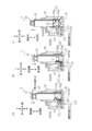
- b) is a diagram showing a state in which the advancing / retreating member is slightly retracted from the first position and the slider side engaging portion is engaged with the advancing side engaged portion
- (c) is a diagram showing a state in which the advancing / retreating member is further retracted. It is the figure which showed the state which reached the 3rd position, and the sliding part came into contact with 2nd cam surface. It is a figure which showed the operation procedure of the advancing / retreating moving device which concerns on one Embodiment of this invention with time, and (a) shows the state which the advancing / retreating member retracted from a third position and came into contact with a housing lid body.
- (B) is a view showing a state in which the advancing / retreating member slightly advances from the state of being in contact with the housing lid and the sliding portion is in contact with the first cam surface. Is a diagram showing a state in which the advancing / retreating member further advances and reaches the second position.
- FIGS. 1 to 9 the configuration of the advancing / retreating moving device 1 according to the embodiment of the present invention will be described with reference to FIGS. 1 to 9.
- the vertical direction, the front-back direction, and the left-right direction of the advancing / retreating moving device 1 are defined and described by the directions of the arrows shown in FIGS. 1 to 4.
- the forward side and the backward side in the operation direction of the advancing / retreating member are defined and described by the directions of the arrows shown in FIGS. 1 to 6.
- the advance / retreat moving device 1 in the present embodiment is a device that can switch the state of an object by moving the advancing / retreating member to the first position or the second position.
- an advancing / retreating moving device for example, in an opening in which a fuel filler port of a vehicle is housed, an opening / closing device for opening / closing a door (fuel lid) for opening or closing the opening is provided, and an advancing / retreating member is provided.
- An advancing / retreating moving device that switches the fuel lid, which is an object, to a locked state in the closed state or a state in which the fuel lid is released from the locked state and can be displaced to the open state can be mentioned.
- the application example of the advancing / retreating moving device 1 is not limited to this embodiment, and can be applied to other devices having a similar configuration.
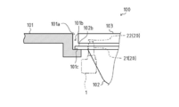
- the opening / closing device 100 is a device that opens or closes the opening in which the fuel filler port 106 of the vehicle is housed.
- the switchgear 100 is configured as a so-called fuel inlet box, and is a device installed in a refueling opening 101a in the vehicle body 101 for injecting fuel into a fuel tank (not shown) of the vehicle.
- the switchgear 100 mainly includes a box body 102 attached to the refueling opening 101a of the vehicle body 101, a fuel lid 103 which is a door capable of closing the refueling opening 101a, a hinge 104 which rotatably supports the fuel lid 103, and an advance / retreat movement.
- the device 1 and the like are provided.
- the box body 102 is attached so as to cover the refueling opening 101a from the back side (inside side of the vehicle) of the vehicle body 101, and refueling chamber that surrounds the refueling pipe (not shown) connected to the fuel tank on the refueling port 106 side. It constitutes 105.
- the refueling pipe fitted into the box main body 102 is arranged so as to protrude in the box main body 102, and constitutes the refueling port 106.
- the fuel filler port 106 is closed by the screw cap 107.
- the screw cap 107 has a structure that can be removed from the refueling port 106, for example, when refueling.
- a step 101b is formed on the peripheral edge of the refueling opening 101a with respect to the front side (outer side of the vehicle) surface of the vehicle body 101 so that the front side (the front side of the vehicle body 101) (
- An annular surface portion 101c is formed recessed from the surface on the outer side of the vehicle to the back side (inner side of the vehicle) of the vehicle body 101, and the box body 102 is formed on the front side (inside of the vehicle) of the vehicle body 101 via the flange 102b. It is attached to the annular surface portion 101c from the outer side of the vehicle).
- the advancing / retreating moving device 1 includes an advancing / retreating member 20 and a locking portion 22 provided at the tip of the advancing / retreating member 20, and opens and closes the fuel lid 103 by advancing / retreating the advancing / retreating member 20.
- the fuel lid 103 is provided with a locked portion 103a to which the locking portion 22 of the advancing / retreating member 20 can be locked, and the locked portion 103a is locked, for example. It is configured by a hole with an opening through which the locking portion 22 can pass when the portion 22 is at a predetermined angular position.
- the switchgear 100 having such a configuration, when the fuel lid 103 is closed, the fuel lid 103 pushes the advancing / retreating member 20, so that the advancing / retreating member 20 retracts to the back side (inside side of the vehicle) of the vehicle body 101.
- the locking portion 22 of the advancing / retreating member 20 is placed at a predetermined angular position (in the figure, in the drawing). Since it is located at the position of the locking portion 22 indicated by the alternate long and short dash line), it is inserted into the locked portion 103a through the opening of the locked portion 103a.
- the locking portion 22 located inside the locked portion 103a rotates and its angular position changes (in FIG. 9, the locking shown by the solid line).
- the position of the portion 22) the locking portion 22 is locked to the inner surface of the locked portion 103a.
- the locking portion 22 is locked to the locked portion 103a, so that the fuel lid 103 is locked in the closed state.
- the advancing / retreating member 20 may have the vehicle body 101.
- the urging force that advances to the front side (outside side of the vehicle) does not work. Therefore, the fuel lid 103 does not open.
- the advancing / retreating moving device 1 mainly includes a housing 10, an advancing / retreating member 20, an advancing / retreating position control mechanism 30, a slider 40, a regulating mechanism 50, and the like.
- the advancing / retreating member 20 is provided so as to be able to advance / retreat with respect to the housing 10. Further, the advancing / retreating member 20 is controlled by the advancing / retreating position control mechanism 30 to move forward / backward between the first position Pa1 and the second position Pa2.
- the first position Pa1 means a predetermined position of the advancing / retreating member 20 set on the forward side
- the second position Pa2 means the advancing / retreating member 20 set on the retreating side with respect to the first position Pa1. It means a predetermined position.
- FIG. 1A shows a state in which the advancing / retreating member 20 has reached the first position Pa1 in the advancing position.
- a slider 40 that can move in the advancing / retreating direction is engaged with the advancing / retreating member 20, and the regulation mechanism 50 locks the advancing / retreating member 20 through the slider 40 to move the advancing / retreating member 20 forward / backward. It has a regulateable structure.
- the slider 40 is located on one side of the advancing / retreating member 20 on the retracting side (lower end portion in the present embodiment) in the direction orthogonal to the advancing / retreating direction (vertical direction in the present embodiment) (in the present embodiment). , Rear side), and is engaged with the advancing / retreating member 20.
- the advancing / retreating position control mechanism 30 is mainly provided over a range S from the retreating side end portion of the advancing / retreating member 20 to the stroke region S of the retreating side end portion.
- the regulation mechanism 50 is arranged so as not to protrude to the backward side with respect to the region S.
- the advancing / retreating position control mechanism 30 and the regulating mechanism 50 are within the range in which the advancing / retreating member 20 is located when the advancing / retreating member 20 advances / retreats in the axial direction of the advancing / retreating member 20.
- the size of the advancing / retreating member 20 in the advancing / retreating direction of the advancing / retreating moving device 1 as a whole is reduced.
- the housing 10 has an accommodating portion that holds each component such as the advancing / retreating member 20, the advancing / retreating position control mechanism 30, the slider 40, and the regulating mechanism 50 by the positional relationship described later. It consists of a housing structure.
- the housing 10 extends in one direction (in the present embodiment, in the front-rear direction) and has a substantially rectangular parallelepiped shape with an open lower surface, and a housing lid that closes the opening 11a of the housing body 11. It is composed of a body 12 and the like.
- each component such as the advancing / retreating member 20 is housed in a predetermined position inside the housing 10 mainly through the opening 11a of the housing body 11, and then the opening 11a is closed by the housing lid 12.
- the electric motor 52A and the engaging member 51 of the regulation mechanism 50 which will be described later, and the advancing / retreating position. It also functions as a pedestal for the urging member 31 of the control mechanism 30, but is not limited to this. That is, a member having a function as a pedestal of these electric motors 52A and the like may be separately provided, and the function of the housing lid 12 may be limited to the function as a closing member for closing the opening of the housing body 11.
- a through hole through which the advancing / retreating member 20 can pass is provided on one side surface of the housing 10, and the advancing / retreating member 20 is provided so as to be able to advance / retreat with respect to the housing 10 through the through hole.
- the housing 10 is provided with a guide portion for guiding the moving direction of the advancing / retreating movement of the advancing / retreating member 20.
- a through hole 11b corresponding to the through hole and communicating with the inside of the housing 10 is provided on the side surface of the housing body 11 opposite to the opening 11a side, that is, at one end of the upper surface.
- the advance / retreat member 20 is provided so as to be movable back and forth with respect to the housing 10 through the through hole 11b.
- a hollow through passage portion 11c extending in an upright direction with respect to the upper surface of the housing main body 11 corresponding to the guide portion is provided on the peripheral edge portion of the through hole 11b, and the inside of the through passage portion 11c.
- the advancing / retreating member 20 is guided by the penetrating passage portion 11c in the moving direction of the advancing / retreating movement without rattling.
- the first cam surface 13 and the second cam surface 14 constituting the advancing / retreating position control mechanism 30 and the second cam surface 14 forming the advancing / retreating position control mechanism 30 along the movement locus of the end of the advancing / retreating member 20 on the retreating side when advancing / retreating.
- a slider guide portion 11d for guiding the movement of the slider 40 is provided. The details of the first cam surface 13, the second cam surface 14, and the slide guide portion 11d will be described later.
- the advancing / retreating member 20 is a member capable of advancing / retreating with respect to the housing 10. Specifically, as shown in FIG. 1A, the advancing / retreating member 20 can move to the first position Pa1 that has moved forward and the second position Pa2 that has moved backward.
- advancing means moving toward the outside of the housing 10, and retreating means moving toward the inside of the housing 10.
- the first position Pa1 is the stop position of the advancing / retreating member 20 that has moved forward
- the second position Pa2 is the stopping position of the advancing / retreating member 20 that has moved backward. Therefore, for example, as in the present embodiment, when the forward-moving region of the advancing / retreating member 20 is located outside the housing 10 at any of the forward-side first position Pa1 and the backward-side second position Pa2.
- a specific portion of the advancing / retreating member 20, for example, a locking portion 22 located at the tip of the advancing / retreating member 20 on the forward side is farther from the housing 10 than at the second position Pa2.
- the first position Pa1 is a position where the locking portion 22 and the locked portion 103a (see FIG. 7) of the fuel lid 103 are in the unlocked state and the fuel lid 103 is in the open state.
- the second position Pa2 is a position where the locking portion 22 and the locked portion 103a of the fuel lid 103 are locked and the fuel lid 103 is held in the closed state.
- the forward-moving region of the advancing / retreating member 20 may be located inside the housing 10 at any of the first position Pa1 and the second position Pa2.
- a specific portion of the advancing / retreating member 20, for example, the locking portion 22 of the advancing / retreating member 20 is closer to the outside of the housing 10 than at the second position Pa2.
- the region on the forward side of the advancing / retreating member 20 is located outside the housing 10, and at the second position Pa2, the region on the advancing side of the advancing / retreating member 20 is located. It may be located inside the housing 10. In this case, a specific portion of the advancing / retreating member 20, for example, the locking portion 22 of the advancing / retreating member 20 will appear and disappear from the housing 10.
- the advancing / retreating member 20 is provided in the housing 10 so as to advance / retreat while rotating relative to the housing 10.
- the advancing / retreating member 20 has a cylindrical or cylindrical rod portion 21 and a locking portion 22 provided at the tip of the rod portion 21 on the forward side. Then, the advancing / retreating member 20 is arranged in the housing 10 so that the locking portion 22 can advance to engage with the engaging object.
- the engaged portion 23 is a portion that engages with the slider 40 described later in the axial direction of the rod portion 21 so as to be relatively rotatable, and engages with the slider 40 in the vicinity of the retracted end portion of the rod portion 21. It has an engaging portion 23a and a forward side engaged portion 23b that engages with the slider 40 on the forward side as compared with the retracting side engaged portion 23a.
- the retracted side engaged portion 23a is a portion provided on the outer periphery of the retracting side of the advancing / retreating member 20, and the advancing side of the retracting side engaged portion 23a abuts on the retracting side of the slider 40.
- the forward-side engaged portion 23b has an abutting surface provided in the axial direction with respect to the axis of the advancing / retreating member 20 on the retracting side, and this abutting surface with respect to the slider 40.
- the advancing side engaged portion 23b may be engaged with the slider 40 when the position of the advancing / retreating member 20 around the axis is a position where the advancing / retreating member 20 needs to be suppressed from advancing by the slider 40.
- it is provided as an annular sliding surface facing the forward side.
- the retracted side engaged portion 23a is provided as a step portion having an annular sliding surface.
- the distance between the retracted side engaged portion 23a and the forward side engaged portion 23b is such that the slider 40 engaged with the advancing / retreating member 20 can move somewhat relative to the advancing / retreating member 20 in the advancing / retreating direction. It is set.
- the distance between the retracted side engaged portion 23a and the forward side engaged portion 23b is the housing side cam including the first cam surface 13 and the second cam surface 14 when the advancing / retreating member 20 is pushed in. The distance may be such that the advancing / retreating member 20 does not rotate forward due to engagement with the mechanism.
- a sliding portion 24 that slides on the first cam surface 13 and the second cam surface 14 to rotate the advancing / retreating member 20 is provided between the retracting side engaged portion 23a and the advancing side engaged portion 23b. You may.
- the sliding portion 24, together with the first cam surface 13 and the second cam surface 14 is a portion constituting the advance / retreat position control mechanism 30, and is in contact with the first cam surface 13 on the forward side. It has a possible forward-side contact portion 24a and a backward-side contact portion 24b capable of contacting the second cam surface 14 on the backward side.
- the sliding portion 24 can rotate the advancing / retreating member 20 in the axial direction by sliding with the first cam surface 13 and the second cam surface 14 described later.
- As the first cam surface 13 and the second cam surface 14 a structure used in a known rotary cam mechanism that rotates around an axis by reciprocating in the axial direction can be adopted.
- the advancing / retreating member 20 having such a configuration is passed through the through passage portion 11c with the locking portion 22 facing forward, and is inserted into the through hole 11b.
- the advancing / retreating member 20 is held slidably while being restricted from moving in the direction orthogonal to the axial direction by the through passage portion 11c.
- a wall surface 10a in contact with the outer peripheral surface of the advancing / retreating member 20 is provided, a first cam surface 13 is formed on the forward side of the wall surface 10a, and a first cam surface 13 is formed on the backward side.
- the two cam surface 14 is formed.
- the advancing / retreating member 20 is arranged so that the engaged portion 23 is located between the first cam surface 13 and the second cam surface 14 provided on the wall surface 10a.
- the sliding portion 24 comes into contact with the first cam surface 13 and slides, and when the advancing / retreating member 20 moves in the backward direction, the sliding portion 24 moves to the second cam. It comes into contact with the surface 14 and slides, and the advancing / retreating member 20 rotates about the axis. That is, the advancing / retreating member 20 moves forward / backward while rotating about the axis as an example of moving forward / backward while rotating relative to the housing 10.
- the detailed configuration of the sliding portion 24 and the first cam surface 13 and the second cam surface 14 will be described later.
- the first cam surface 13 and the second cam surface 14 are examples of a locus guide portion that guides the advance / retreat member 20 along the locus of rotational movement of the advance / retreat member 20, and the sliding portion 24 is guided by the locus guide portion. This is an example of a tracked guide unit.
- the advancing / retreating member 20 may be provided with a locus guide portion such as a cam surface, and the wall surface 10a of the housing 10 may be provided with a locus guide portion such as a sliding portion. That is, in either one of the housing 10 and the advancing / retreating member 20, a locus guide portion for guiding the moving locus of the advancing / retreating member 20 is provided so as to advance / retreat while rotating relative to the housing 10, and on the other hand, It is possible to adopt a configuration in which a tracked guide section is provided to be guided by the track guide section.
- the advancing / retreating position control mechanism 30 is a mechanism that controls the advancing / retreating member 20 to advance / retreat to the first position Pa1 that is advanced with respect to the housing 10 and the second position Pa2 that is retracted. ..
- the advancing / retreating position control mechanism 30 has a moving function of moving the advancing / retreating member 20 in the advancing / retreating direction, and also has a stopping function of stopping the advancing / retreating member 20 at the first position Pa1 on the forward side or the second position Pa2 on the backward side.
- the mechanism 30 includes a portion provided on the housing 10 and a portion provided on the advancing / retreating member 20 which are configured to control these positional relationships.
- the advancing / retreating position control mechanism 30 is an example of the housing side member, and the first cam surface 13 provided on the wall surface 10a of the housing 10 (see FIG. 1A).
- This is an example of a portion provided on the advancing / retreating member 20 guided by the second cam surface 14, the first position contact portion 15, the second position contact portion 16, the first cam surface 13, and the second cam surface 14. Therefore, it is composed of a sliding portion 24 provided on the advancing / retreating member 20, an urging member 31 (see FIG. 1A), and the like.
- the first cam surface 13 slides the sliding portion 24 of the advancing / retreating member 20 to rotate the advancing / retreating member 20 in the rotation direction centered on the axis, and the sliding portion 24 is positioned at the first position. It leads to the contact portion 15 or the second position contact portion 16. Further, the second cam surface 14 rotates the advancing / retreating member 20 in the rotation direction about the axis by sliding the sliding portion 24 of the retreating advancing / retreating member 20.
- the direction of rotation of the advancing / retreating member 20 by the first cam surface 13 and the direction of rotation of the advancing / retreating member 20 by the second cam surface 14 are the same, but the direction is limited to this. However, both rotation directions may be set to be opposite to each other.
- the first position contact portion 15 comes into contact with the sliding portion 24 of the advance / retreat member 20 located at the first position Pa1, and stops the advance / retreat member 20 at the first position Pa1.
- the second position contact portion 16 comes into contact with the sliding portion 24 of the advance / retreat member 20 located at the second position Pa2, and stops the advance / retreat member 20 at the second position Pa2.
- the sliding portion 24 provided on the advancing / retreating member 20 includes a forward-side contact portion 24a capable of contacting the first cam surface 13, a retract-side contact portion 24b capable of contacting the second cam surface 14, and a rear contact portion 24b.
- the rotary-side contact portion 24c capable of contacting the first position contact portion 15 and the second position contact portion 16 is provided.
- the forward-side contact portion 24a is formed based on the locus drawn by the sliding portion 24 in the advancing / retreating member 20 that rotates about the axis while advancing.
- the rotation of the advancing / retreating member 20 It is composed of an inclined surface that gradually inclines toward the forward side in the direction.
- the retracting side contact portion 24b is formed based on the locus drawn by the sliding portion 24 in the advancing / retreating member 20 that rotates about the axis while retreating.
- the advancing / retreating member 20 It is composed of an inclined surface that gradually inclines toward the receding side in the direction of rotation.
- the rotating side contact portion 24c can regulate the movement of the advancing / retreating member 20 in the rotational direction. Therefore, for example, in the present embodiment, the rotating side contact portion 24c is tangent to the rotational direction of the advancing / retreating member 20 (that is, the outer peripheral surface of the advancing / retreating member 20). It is composed of planes that are orthogonal to the direction).
- the sliding portion 24 is composed of a substantially triangular protrusion having a peripheral edge formed by the forward contact portion 24a, the backward contact portion 24b, and the rotation side contact portion 24c.
- the present invention is not limited to this, and as long as it has at least the forward side contact portion 24a, the backward side contact portion 24b, and the rotation side contact portion 24c, it slides by other polygonal protrusions.
- the unit 24 may be configured.
- the first position contact portion 15 is a first position forward side contact formed of an inclined surface formed along the forward side contact portion 24a of the sliding portion 24 in the advancing / retreating member 20 located at the first position Pa1. It is composed of a contact portion 15a and a first position rotating side contact portion 15b formed of a flat surface formed along the rotating side contact portion 24c of the sliding portion 24.
- the second position abutting portion 16 is a second position advancing side contact formed of an inclined surface formed along the advancing side abutting portion 24a of the sliding portion 24 in the advancing / retreating member 20 located at the second position Pa2. It is composed of a contact portion 16a and a second position rotating side contact portion 16b formed of a flat surface formed along the rotating side contact portion 24c of the sliding portion 24.
- first cam surface 13 is formed along the locus drawn by the forward side contact portion 24a of the sliding portion 24 in the advancing / retreating member 20 that rotates about the axis while advancing toward the first position Pa1. Sliding on the first forward-side inclined surface 13a, which is provided continuously with the first position contact portion 15, and the advancing / retreating member 20 that rotates about the axis while advancing toward the second position Pa2. It is formed along the locus drawn by the forward-side contact portion 24a of the portion 24, and is composed of a second forward-side inclined surface 13b and the like which are provided continuously with the second position contact portion 16.
- the second cam surface 14 is formed along the locus drawn by the retracting side contact portion 24b of the sliding portion 24 in the advancing / retreating member 20 that rotates about the axis while retracting from the first position Pa1.
- the advancing / retreating member 20 that rotates about the axis while retreating from the first retracting side inclined surface 14a and the second position Pa2 is formed along the locus drawn by the retracting side abutting portion 24b of the sliding portion 24. It is composed of a second receding side inclined surface 14b and the like.
- the first forward-side inclined surface 13a of the first cam surface 13 is in contact with the second position on the other side, which is the opposite side to the one continuous with the first position contact portion 15.
- the portions 16 are also continuously provided, and when the position of the advancing / retreating member 20 is displaced from the second position Pa2 to the first position Pa1, the sliding portion 24 slides on the first forward side inclined surface 13a.
- the advancing / retreating member 20 rotates about the axis while advancing.
- the housing side member (first cam surface 13, second cam surface 14, first position contact portion 15, and second position contact portion 16) having such a configuration, and a sliding portion.
- a so-called push-push mechanism is configured by the 24, and the sliding portion 24 slides on the first cam surface 13 or the second cam surface 14, while the first position contact portion 15 and the second position contact portion 15 and the second position contact portion.
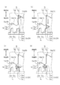
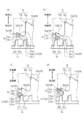
- the sliding portion 24 When the advancing / retreating member 20 stopped at the first position Pa1 is moved in the retreating direction, the sliding portion 24 also moves in the retreating direction accordingly. At this time, as shown in FIG. 5B, the sliding portion 24 moves in the backward direction while sliding in contact with the first position rotating side contact portion 15b of the first position contact portion 15. Then, when the advancing / retreating member 20 reaches the third position Pa3 (see FIG. 1) which is further retracted from the second position Pa2, the sliding portion 24 hits the first retracting side inclined surface 14a of the second cam surface 14. Touch.
- the retractable end of the advancing / retreating member 20 comes into contact with the housing lid 12 (see FIG. 1) of the housing 10, and the advancing / retreating member 20 advances / retreats to a position where the movement of the advancing / retreating member 20 in the retreating direction is hindered.
- the moving direction of the advancing / retreating member 20 is changed from the retreating direction to the advancing direction.
- the advancing / retreating member 20 whose moving direction is changed in the advancing direction moves in the advancing direction without rotating in the rotational direction about the axis.
- the sliding portion 24 also moves in the forward direction and comes into contact with the second forward side inclined surface 13b of the first cam surface 13.
- the sliding portion 24 reaches the second position contact portion 16, and the movement of the sliding portion 24 in the forward direction and the rotation direction is restricted by the second position contact portion 16.
- the advancing / retreating member 20 is re-regulated from moving in the forward direction and moving in the rotational direction about the axis, and is stopped at the second position Pa2 by the advancing / retreating position control mechanism 30.
- the sliding portion 24 When the advancing / retreating member 20 stopped at the second position Pa2 is moved in the retreating direction again, the sliding portion 24 also moves in the retreating direction accordingly. At this time, as shown in FIG. 6B, the sliding portion 24 moves in the backward direction while sliding in contact with the second position rotating side contact portion 16b of the second position contact portion 16. Then, when the advancing / retreating member 20 reaches the third position Pa3 again, the sliding portion 24 comes into contact with the second retracting side inclined surface 14b of the second cam surface 14.
- the advancing / retreating member 20 whose moving direction is changed in the advancing direction moves in the advancing direction without rotating in the rotational direction about the axis.
- the sliding portion 24 also moves in the forward direction and comes into contact with the first forward side inclined surface 13a of the first cam surface 13.
- the sliding portion 24 comes into contact with the first forward-side inclined surface 13a of the first cam surface 13, and then the advancing / retreating member 20 is further moved in the forward direction, the sliding portion 24 becomes the first forward-side inclined surface. It slides on 13a and moves in the forward direction and the rotation direction. As a result, the advancing / retreating member 20 is rotated in the rotational direction around the axis again while moving in the forward direction.
- the sliding portion 24 reaches the first position contact portion 15, and the first position contact portion 15 causes the sliding portion 24 to move in the forward direction and the rotational direction. Be regulated.
- the advancing / retreating member 20 is restricted from moving in the forward direction and moving in the rotational direction about the axis, and is returned to the state of being stopped at the first position Pa1 again by the advancing / retreating position control mechanism 30.
- Such a housing side member first cam surface 13, second cam surface 14, first position contact portion 15, and second position contact portion 16
- an engaging portion sliding of the advancing / retreating member 20.
- the configuration of the push-push mechanism including the parts 24) is not limited to the present embodiment, and as described above, rotation about the axis between the first position Pa1 and the second position Pa2. Any configuration may be used as long as the advancing / retreating member 20 can be moved forward / backward while rotating in the direction.
- the urging member 31 urges the advancing / retreating member 20 in the axial direction of the advancing / retreating member 20, particularly in the advancing direction.
- the urging member 31 is composed of, for example, a compression coil spring, and is arranged coaxially with the advancing / retreating member 20 on the retracting side of the advancing / retreating member 20 inside the housing 10.
- the urging member 31 is not limited to the compression coil spring, and other members such as leaf springs can be adopted.
- one end of the urging member 31 is inserted into the concave advancing / retreating member side holding portion 25 (see FIG. 1B) provided on the end surface of the advancing / retreating member 20 on the retreating side, and the housing lid 12 The other end is inserted into and held by a concave housing-side holding portion (not shown) provided on the upper surface (the inner surface of the housing 10).
- the urging member 31 exerts an urging force on the advancing / retreating member 20 in the advancing direction of the advancing / retreating member 20.
- the sliding portion 24 of the advancing / retreating member 20 is the first cam surface 13 or the first position contact portion when the advancing / retreating member 20 is urged in the forward direction by the urging member 31. It is regulated by abutting with 15 or the second position contact portion 16 (see FIG. 5). Further, the movement of the advancing / retreating member 20 in the retreating direction is generated by an external force.
- the urging member 31 compressed in the axial direction of the advancing / retreating member 20 is held by the advancing / retreating member side holding portion 25 and the housing side holding portion 25.
- the advancing / retreating member 20 is restricted from moving in the retreating direction by being accommodated in the space formed by the portions and coming into contact with the retracting end surface of the advancing / retreating member 20 and the upper surface of the housing lid 12. There is.
- the space required on the retracting side of the advancing / retreating member 20 is substantially sufficient only in the region S where the end of the advancing / retreating member 20 on the retracting side strokes, and the advancing / retreating moving device 1 as a whole moves forward / backward.
- the size of the moving device 1 as a whole is reduced in the advancing / retreating direction of the advancing / retreating member 20.
- the slider 40 is an engaging member that engages with the advancing / retreating member 20 so as to be relatively movable, and abuts and engages with the engaging member 51 of the regulation mechanism 50 described later to lock the advancing / retreating movement of the advancing / retreating member 20.
- the slider 40 engages with the radial outer side of the advancing / retreating member 20 so as to project with respect to the advancing / retreating member 20 toward the side orthogonal to the axis of the advancing / retreating member 20.
- the slider 40 is provided so as to be movable in the advancing / retreating direction of the advancing / retreating member 20 together with the advancing / retreating member 20.
- the slider 40 and the advancing / retreating member 20 within a predetermined region in the advancing / retreating direction of the advancing / retreating member 20 (in the present embodiment, the region between the advancing / retreating side engaged portion 23b and the retreating side engaged portion 23a). It is provided so that it can move relatively in the forward and backward directions.
- the slider 40 is provided so as to be relatively movable in the rotational direction about the axial center of the advancing / retreating member 20 when the advancing / retreating member 20 rotates in the axial direction. Further, the slider 40 can be axially engaged with the forward side engaged portion 23b and the backward side engaged portion 23a and can move in the backward direction and the forward direction, respectively.
- the slider 40 has a slider main body 41 that can be engaged with the engaging member 51 of the regulation mechanism 50, and a slider-side engaging portion 42 that can be engaged with the advancing / retreating member 20.
- the slider main body 41 has a slider-side engaging surface 41a that engages with the engaging member 51 on one side (retracting side in this embodiment) in the advancing / retreating direction, and the housing 10. It has a sliding surface 41b that is slidable in contact with the slider guide portion 11d provided in the above. Further, the slider side engaging portion 42 is provided so as to extend from the slider main body portion 41 in a direction orthogonal to the advancing / retreating direction of the advancing / retreating member 20 and toward the advancing / retreating member 20 side.
- the slider 40 is arranged adjacent to the radial outer side of the advancing / retreating member 20 in the region between the advancing / retreating member 20 and the retracting side engaged portion 23a, and is engaged on the slider side. It is provided so as to be engageable with the forward-side engaged portion 23b and the backward-side engaged portion 23a via the portion 42.
- the slider 40 engages with the retracting side engaged portion 23a via the slider side engaging portion 42, and advances as the advancing / retreating member 20 moves forward.
- the slider 40 engages with the advancing side engaged portion 23b via the slider side engaging portion 42, and retracts as the advancing / retreating member 20 retracts.
- the slider 40 engages with the advancing / retreating member 20 on the advancing side engaged portion 23b or the retracting side engaged portion 23a via the slider side engaging portion 42, so that the advancing / retreating member 20 and the advancing / retreating member 20 move in the advancing / retreating direction. It is possible to move to. Further, the slider 40 is relative to the advancing / retreating member 20 between the position where the slider side engaging portion 42 engages with the forward side engaged portion 23b and the position where the slider side engaging portion 42 engages with the retracting side engaged portion 23a. In addition, it can move in the forward and backward directions.
- the slider 40 engages with the forward-side engaged portion 23b or the backward-side engaged portion 23a of the advancing / retreating member 20 via the slider-side engaging portion 42 on the forward side or the backward side in the advancing / retreating direction, the slider 40 engages with the advancing / retreating member 20. It is movable in the rotational direction relative to the advancing / retreating member 20.
- the housing 10 is provided with a slider guide portion 11d that guides the movement of the slider 40.
- the slider guide portion 11d is composed of a groove portion having a bottom surface capable of contacting the sliding surface 41b of the slider main body portion 41, and as shown in FIG. In the moving slider 40, it is formed along the moving locus of the slider main body 41.
- the slider 40 slides the slider guide portion 11d via the sliding surface 41b of the slider main body 41, so that the moving direction relative to the housing 10 is restricted only to the advancing / retreating direction, and the advancing / retreating member. Along with 20, the direction of movement when moving forward and backward is guided.
- the regulation mechanism 50 will be described with reference to FIG. As shown in FIG. 1B, the regulation mechanism 50 has an engaging member 51 that can engage with the slider 40, and a driving unit 52 that moves the engaging member 51 between the engaging position Pb1 and the separation position Pb2. This is a mechanism for locking the advancing / retreating movement of the advancing / retreating member 20 by engaging the engaging member 51 with the slider 40.
- the engaging position Pb1 refers to the movement locus of the slider 40 that moves forward and backward with the advancing / retreating member 20, and the engaging member side engaging surface 51a of the engaging member 51 described later (see FIG. 1A). Means a predetermined position where the engaging member 51 can engage with the slider 40.
- the separation position Pb2 is a position in which the engagement member side engagement surface 51a of the engagement member 51 is separated from the movement locus of the slider 40 that moves forward and backward with the advance / retreat member 20. It means a predetermined position where the engaging member 51 is separated from the slider 40.
- the drive unit 52 moves the engaging member 51 in the linear direction between the engaging position Pb1 and the separating position Pb2. Specifically, the drive unit 52 moves the engaging member 51 in a direction intersecting the advancing / retreating direction of the advancing / retreating member 20, in other words, in a linear direction on a virtual plane intersecting the axial direction of the advancing / retreating member 20, and engages with the engaging member 51.
- the engaging member 51 is brought to reach the matching position Pb1 or the separating position Pb2.
- the drive unit 52 has an electric motor 52A as a drive source, a worm gear 52B coaxially provided on the drive shaft 52A1 of the electric motor 52A, and the like, and the engaging member 51 is provided via the worm gear 52B. Is connected with. Then, the rotational motion of the electric motor 52A is converted into a linear motion by the worm gear 52B, and the engaging member 51 is moved in a linear direction between the engaging position Pb1 and the separation position Pb2 by the drive of the driving unit 52. ..
- a terminal 43 is provided on the lower surface of the housing lid 12 (the surface on the outer side of the housing 10), and the electric motor 52A is connected to the terminal 43. Power is supplied from the outside by relaying the terminal 43.
- the drive unit 52 may, for example, lock the advancing / retreating member 20 by driving it independently. However, in the case where the drive unit 52 is provided in a vehicle or the like, the drive unit 52 moves in and out in conjunction with locking by key operation of the vehicle. A locking operation may be performed on the member 20.
- the engaging member 51 slides in contact with the slider-side engaging surface 41a of the slider 40, the engaging member-side engaging surface 51a that can be engaged, and the upper surface of the housing lid 12 (the inner surface of the housing 10). It has a possible sliding surface 51b and a gear portion 51c to which the drive of the drive portion 52 is transmitted.
- the engaging member side engaging surface 51a is provided on the other side of the advancing / retreating member 20 in the advancing / retreating direction (in the present embodiment, the advancing side), and as described above, one side of the slider main body 41 in the advancing / retreating direction (the advancing / retreating direction). It engages with the slider side engaging surface 41a provided on the retracting side).
- the engaging member side engaging surface 51a may be provided on one side (retracting side) of the advancing / retreating member 20 in the advancing / retreating direction.
- the slider main body 41 of the slider 40 is in the advancing / retreating direction.
- the slider side engaging surface 41a is provided on the other side (advance side).
- the locking member 51 can prevent the advancing / retreating member 20 from advancing toward the first position Pa1 by engaging with the slider 40. Therefore, as will be described later, for example, the second position Pa2 or the third position In order to move the advancing / retreating member 20 located at the position Pa3 toward the first position Pa1, it is necessary to temporarily move the advancing / retreating member 20 further to the backward side from the third position Pa3, and the second position Pa2 or the third When the advancing / retreating member 20 located at the position Pa3 is prevented from advancing toward the first position Pa1, the engaging member side engaging surface 51a of the engaging member 51 may be used as in the present embodiment.
- the slider 40 engaging surface 41a is provided on the other side (advancing side) of the advancing / retreating member 20 in the advancing / retreating direction, and the slider side engaging surface 41a of the slider 40 is provided on one side (retracting side) of the advancing / retreating direction. Engage with the slider 40 on the forward side.
- the engaging member side engaging surface 51a of the engaging member 51 Is provided on one side (reverse side) of the advancing / retreating member 20 in the advancing / retreating direction, and the slider side engaging surface 41a of the slider 40 is provided on the other side (advancing side) of the advancing / retreating direction. , Engages with the slider 40 on the retracted side.
- the engaging member 51 is provided with a sliding surface on the forward side that slides with the slider 40 when the slider 40 moves backward in the engaging portion that engages with the slider 40, and engages with the forward side of the slider 40.
- a locking surface that suppresses the movement of the slider 40 may be provided on the retracting side.
- the sliding surface of the engaging member 51 with the slider 40 provided on the forward side may be, for example, an inclined surface facing the forward side and inclining toward the backward side. Further, since the engaging member 51 has a sliding surface with the slider 40, the engaging member 51 can be moved by pushing the advancing / retreating member 20 in the backward direction.
- the gear portion 51c is configured by a reduction mechanism having a helical gear inside.
- the worm gear 52B of the drive unit 52 is penetrated through the gear portion 51c, and the gear portion 51c meshes with the worm gear 52B via the internal helical gear.
- the engaging member 51 is connected to the drive unit 52 via the gear unit 51c, and the drive of the electric motor 52A is transmitted to the gear unit 51c via the worm gear 52B, whereby the worm gear 52B (or electric motor) is transmitted. It is moved in a linear direction along the axis of the drive shaft 52A1) of the motor 52A.
- the regulation mechanism 50 having such a configuration is arranged so that the moving direction of the engaging member 51 intersects with the moving direction of the slider 40 that moves forward and backward with the advancing / retreating member 20 on the retracting side of the advancing / retreating member 20. ..
- the engaging member 51 is moved in the linear direction, that is, in the axial direction of the drive shaft 52A1 by the worm gear 52B provided coaxially with the drive shaft 52A1 of the electric motor 52A.
- the engaging member side engaging surface 51a is located on the retracting side of the slider side engaging surface 41a in the slider 40, and the engaging member 51
- the worm gear 52B and the electric motor 52A are arranged so as to be positioned toward the side (in the present embodiment, the rear side) away from the advancing / retreating member 20 in order along the moving direction of the worm gear 52B and the electric motor 52A.
- the driving unit 52 of the regulation mechanism 50 moves the engaging member 51 toward the side away from the advancing / retreating member 20 (rear side), that is, the separation position Pb2 along the direction intersecting the advancing / retreating direction of the advancing / retreating member 20.
- the engaging member-side engaging surface 51a of the engaging member 51 moves from the retracting side of the slider-side engaging surface 41a so that the engaging member 51 is separated from the engaged state with respect to the slider 40. It is configured.
- the regulation mechanism 50 having such a configuration, it is possible to arrange the advancing / retreating member 20 so as not to protrude further to the retreating side with respect to the region S where the end portion on the retreating side of the advancing / retreating member 20 strokes. 1 As a whole, the size of the advancing / retreating member 20 in the advancing / retreating direction can be reduced.
- the moving direction of the engaging member 51 and the advancing / retreating direction of the advancing / retreating member 20 are set to intersect in an orthogonal direction, but the present invention is not limited to this, and the engaging member 51 is not limited to this.
- the moving direction of the member 20 and the advancing / retreating direction of the advancing / retreating member 20 may be set to intersect in the inclined direction.
- the configuration of the drive unit 52 is not limited to the configuration of the electric motor 52A and the worm gear 52B as in the present embodiment, and any other configuration can be used as long as the engaging member 51 can be moved in the linear direction. It may be composed of an actuator (for example, an electric cylinder) or the like.
- the advancing / retreating moving device 1 sets the locking state of the advancing / retreating member 20 and the locked portion 103a of the fuel lid 103 (see FIG. 7) in a state where the advancing / retreating member 20 is located at the first position Pa1. It is released and the locked state of the fuel lid 103 is released.
- the advancing / retreating moving device 1 holds a locked state between the locking portion 22 of the advancing / retreating member 20 and the locked portion 103a of the fuel lid 103 in a state where the advancing / retreating member 20 is located at the second position Pa2, and the fuel lid The 103 is locked. Then, the advancing / retreating moving device 1 displaces the position of the advancing / retreating member 20 by operating according to the following procedure, and switches the fuel lid 103 to the locked state or the unlocked state.
- the advancing / retreating moving device 1 is in an unlocked state with respect to the fuel lid 103, and as shown in FIG. 2A, the advancing / retreating member 20 is in a state of being stopped at the first position Pa1 on the forward side. It has become.
- the locking portion 22 of the advancing / retreating member 20 is engaged at a predetermined angular position (in FIG. 9, indicated by a chain double-dashed line) in which the locked state of the fuel lid 103 with the locked portion 103a is released. It is in a state facing the position of the stop 22). Further, as shown in FIG.
- the sliding portion 24 of the advancing / retreating member 20 is in contact with the first position contact portion 15, and the advancing / retreating member 20 is in contact with the urging member 31 (FIG. 5A). 1 (see (a)) is restricted from advancing by urging.
- the slider 40 is in a state in which the slider side engaging portion 42 is in contact with the retracting side engaged portion 23a of the advancing / retreating member 20, and the engaged portion 23 is in contact with the engaging portion 23. On the backward side of the above, it is in a state of being engaged with the advancing / retreating member 20. Further, in the regulation mechanism 50, the engaging member 51 is located at the separation position Pb2, and the engaging member side engaging surface 51a is separated from the movement locus of the slider side engaging surface 41a in the slider 40. It is in a state.
- the slider 40 When an external force pushing the advancing / retreating member 20 in such a state is applied to the retreating side, the advancing / retreating member 20 retreats.
- the slider 40 immediately after the advancing / retreating member 20 starts retreating, as shown in FIG. 2B, the slider 40 is in a state of being temporarily stopped without accompanying the movement of the advancing / retreating member 20, and the advancing / retreating member 20. It moves to the forward side relative to 20.
- the slider-side engaging portion 42 of the slider 40 comes into contact with the forward-side engaged portion 23b of the advancing / retreating member 20, and the slider 40 engages with the advancing / retreating member 20 on the advancing side of the engaged portion 23. ..
- the advancing / retreating member 20 retracts with the slider 40 in the engaged state and reaches the third position Pa3. Further, as shown in FIG. 5B, when the advancing / retreating member 20 reaches the third position Pa3, the sliding portion 24 of the advancing / retreating member 20 comes into contact with the first retracting side inclined surface 14a of the second cam surface 14. ..
- the advancing / retreating member 20 that has reached the third position Pa3 is further moved to the retreating side by an external force pushing it toward the retreating side, and then, as shown in FIG.
- the movement in the backward direction is restricted and stopped.
- the sliding portion 24 of the advancing / retreating member 20 slides on the first retracting side inclined surface 14a of the second cam surface 14.
- the advancing / retreating member 20 rotates in the rotation direction about the axis while retreating from the third position Pa3.
- the end surface of the advancing / retreating member 20 on the retreating side comes into contact with the upper surface of the housing lid 12, and after the movement of the advancing / retreating member 20 in the retreating direction is restricted, the external force applied to the advancing / retreating member 20 is released. Then, as shown in FIG. 3B, the advancing / retreating member 20 is urged by the urging member 31 to move forward. Further, as shown in FIG. 5D, as the advancing / retreating member 20 advances, the sliding portion 24 of the advancing / retreating member 20 also advances and comes into contact with the second advancing side inclined surface 13b of the first cam surface 13.
- the locking portion 22 of the advancing / retreating member 20 is located at a predetermined angular position (the position of the locking portion 22 indicated by the solid line in FIG. 9) that can be locked with the locked portion 103a of the fuel lid 103. Displace in the facing state. As a result, the advancing / retreating moving device 1 is locked with respect to the fuel lid 103.
- the engaging member 51 of the regulation mechanism 50 moves to the engaging position Pb1.
- the slider-side engaging surface 41a of the slider 40 engages with the engaging member-side engaging surface 51a of the engaging member 51.
- the advancing / retreating member 20 is restricted from moving to the forward side by the sliding portion 24 abutting with the second position abutting portion 16, and the slider 40 engages with the engaging member 51.
- the movement to the retreating side is restricted, and the locking mechanism 50 maintains the locked state with respect to the fuel lid 103.
- a spiral third cam surface centered on the axis of the advancing / retreating member 20 is provided between the advancing / retreating member 20 on the advancing side engaged portion 23b and the retreating side engaged portion 23a. 17 (see FIG. 3B) is provided, and as the advancing / retreating member 20 rotates while advancing toward the second position Pa2, the slider 40 uses the slider-side engaging portion 42 as the third cam. While sliding on the surface 17, it is moved to the backward side relative to the advancing / retreating member 20.
- the slider 40 brings the slider side engaging portion 42 into contact with the retracting side engaged portion 23a of the advancing / retreating member 20 to engage the engaged portion 23. It is in a state of being engaged with the advancing / retreating member 20 on the retracting side of.
- the advancing / retreating member 20 to which the external force pushing the retreat side is applied retreats from the second position Pa2 and reaches the third position Pa3 as shown in FIG. 4 (a). Further, as shown in FIG. 6B, when the advancing / retreating member 20 reaches the third position Pa3, the sliding portion 24 of the advancing / retreating member 20 comes into contact with the second retracting side inclined surface 14b of the second cam surface 14. ..
- the advancing / retreating member 20 that has reached the third position Pa3 is further moved to the retreating side by an external force pushing it toward the retreating side, and then, as shown in FIG. 4B, the advancing / retreating member 20 has a housing having an end face on the retreating side.
- the sliding portion 24 of the advancing / retreating member 20 slides on the second retracting side inclined surface 14b of the second cam surface 14.
- the advancing / retreating member 20 rotates in the rotation direction about the axis while retreating from the third position Pa3.
- the end surface of the advancing / retreating member 20 on the retreating side comes into contact with the upper surface of the housing lid 12, and after the movement of the advancing / retreating member 20 in the retreating direction is restricted, the external force applied to the advancing / retreating member 20 is released. Then, as shown in FIG. 4C, the advancing / retreating member 20 is urged by the urging member 31 to move forward. Further, as shown in FIG. 6D, as the advancing / retreating member 20 advances, the sliding portion 24 of the advancing / retreating member 20 also advances and comes into contact with the first advancing side inclined surface 13a of the first cam surface 13.
- the sliding portion 24 of the advancing / retreating member 20 slides on the first advancing side inclined surface 13a of the first cam surface 13, and FIG. As shown in a), it comes into contact with the first position contact portion 15 again.
- the advancing / retreating member 20 advances while rotating in the direction of rotation about the axis, reaches the first position Pa1 again, and stops, as shown in FIG. 2A. ..
- the locking portion 22 of the advancing / retreating member 20 is locked at a predetermined angular position (in FIG. 9, indicated by a chain double-dashed line) in which the locked state of the fuel lid 103 with the locked portion 103a is released. It is displaced toward the position of the portion 22). As a result, the advancing / retreating moving device 1 switches to the unlocked state again with respect to the fuel lid 103.
- the advancing / retreating member 20 located at the first position Pa1 is further set on the retracting side as compared with the third position Pa3. This is performed by temporarily retracting to a position (in the present embodiment, a position where the retracted end of the advancing / retreating member 20 abuts on the upper surface of the housing lid 12), and then advancing toward the second position Pa2. .. Further, when switching from the locked state to the unlocked state with respect to the fuel lid 103, the advancing / retreating member 20 located at the second position Pa2 is temporarily retracted to the predetermined position on the retracting side as compared with the third position Pa3. After that, it is performed by advancing toward the first position Pa1.
- the engaging member 51 of the regulation mechanism 50 is engaged with the slider 40, and the advancing / retreating member 20 retracts from the second position Pa2.
- the engaging member 51 of the regulation mechanism 50 is engaged with the slider 40 so that the sliding portion 24 of the advancing / retreating member 20 hinders the advancing / retreating member 20 toward the first position contact portion 15. It is configured.
- the engaging member 51 is engaged with the slider 40 as in the present embodiment.
- the advancing / retreating member 20 located at the second position Pa2 may be restricted from retreating toward the predetermined position on the retreating side as compared with the third position Pa3, and as another application example, it may be restricted.
- the engaging member 51 may be engaged with the slider 40 to prevent the advancing / retreating member 20 that has retracted from the second position Pa2 to the predetermined position from advancing toward the first position Pa1.
- the advancing / retreating moving device 1 in the present embodiment is between the housing 10, the advancing / retreating member 20 capable of advancing / retreating with respect to the housing 10, and the first position Pa1 on the forward side and the second position Pa2 on the retreating side.
- An advance / retreat position control mechanism 30 that controls the advance / retreat movement of the advance / retreat member 20, a slider 40 that can move in the advance / retreat direction of the advance / retreat member 20 together with the advance / retreat member 20, and a regulation mechanism 50 that can regulate the advance / retreat movement of the advance / retreat member 20.
- a slider 40 that can move in the advance / retreat direction of the advance / retreat member 20 together with the advance / retreat member 20
- a regulation mechanism 50 that can regulate the advance / retreat movement of the advance / retreat member 20.
- the slider 40 has a slider-side engaging portion 42 that engages with the radial outer side of the advancing / retreating member 20, and the regulation mechanism 50 includes an engaging member 51 that engages with the slider 40 and the engaging member 51 as a slider. It has a drive unit 52 that moves between an engaging position Pb1 that engages with 40 and a separation position Pb2 that is separated from the slider 40.
- the slider 40 that engages with the regulation mechanism 50 can be provided on the side of the advancing / retreating member 20, the advancing / retreating moving device 1 as a whole advances / retreats the advancing / retreating member 20. It is possible to reduce the size in the direction.
- the advancing / retreating member 20 has an engaged portion 23 that engages with the slider side engaging portion 42 of the slider 40, and the engaged portion 23 retracts with the slider side engaging portion 42. It has a retractable side engaged portion 23a that engages on the side, and a forward side engaged portion 23b that engages the slider side engaging portion 42 on the forward side. Then, in the housing 10, the slider 40 moves forward as the advancing / retreating member 20 moves forward due to the engagement between the slider side engaging portion 42 and the retracting side engaged portion 23a, and the slider side engaging portion 42 also moves forward.
- the slider guide portion 11d is configured so that the slider 40 moves backward as the advancing / retreating member 20 moves backward by engaging with the forward-side engaged portion 23b.
- the slider 40 provided on the side of the advancing / retreating member 20 is configured to slide with the movement of the advancing / retreating member 20, and thus engages with the slider 40.
- the slider 40 and the engaging member 51 can be engaged when the engaging member 51 of the matching regulation mechanism 50 is located on the side of the retracted advancing / retreating member 20. Therefore, the size of the advancing / retreating moving device 1 as a whole can be reduced in the advancing / retreating direction.
- the advancing / retreating position control mechanism 30 has a sliding portion 24 provided on the advancing / retreating member 20 and a first cam surface 13 that abuts on the sliding portion 24 on the forward side of the sliding portion 24.
- the second cam surface 14 that comes into contact with the sliding portion 24 on the retracting side, and the first position contact portion 15 that the sliding portion 24 contacts in the forward direction when the advancing / retreating member 20 is located at the first position Pa1 and advancing / retreating. It has a push-push mechanism provided with a second position contact portion 16 with which the sliding portion 24 contacts in the forward direction when the member 20 is located at the second position Pa2.
- the advancing / retreating member 20 comes into contact with the second cam surface 14 at the third position Pa3 which is further retracted from the second position Pa2, and the engaging member 51 of the regulation mechanism 50 slides by engaging with the slider 40.
- the portion 24 is configured to hinder the advance of the advancing / retreating member 20 toward the first position contact portion 15.
- the advancing / retreating member 20 rotates due to the sliding portion 24 sliding with the second cam surface 14 due to the retreating of the advancing / retreating member 20 located at the second position Pa2. Or may prevent the rotated advancing / retreating member 20 from advancing. With this configuration, the advance / retreat of the advance / retreat member 20 is locked.
- the drive unit 52 of the regulation mechanism 50 is configured so that the engaging member 51 engages with and separates from the slider 40 by moving the engaging member 51 in the direction intersecting the advancing / retreating direction of the advancing / retreating member 20. Has been done.
- the moving direction of the engaging member 51 and the moving direction of the slider 40 that advances / retreats with the advancing / retreating member 20 intersect.
- the engaging member 51 is moved in a linear direction, that is, in the axial direction of the drive shaft 52A1 by the worm gear 52B provided coaxially with the drive shaft 52A1 of the electric motor 52A.
- the engaging member side engaging surface 51a is located on the retracting side of the slider side engaging surface 41a in the slider 40, and in the moving direction of the engaging member 51.
- the worm gear 52B and the electric motor 52A are arranged so as to be positioned toward the side (in the present embodiment, the rear side) away from the advancing / retreating member 20 in order.
- the regulation mechanism 50 having such a configuration, it is possible to arrange the advancing / retreating member 20 so as not to protrude further to the retreating side with respect to the region S where the end portion on the retreating side of the advancing / retreating member 20 strokes. 1 As a whole, the size of the advancing / retreating member 20 in the advancing / retreating direction can be reduced.
Landscapes
- Engineering & Computer Science (AREA)
- Life Sciences & Earth Sciences (AREA)
- Sustainable Development (AREA)
- Sustainable Energy (AREA)
- Chemical & Material Sciences (AREA)
- Combustion & Propulsion (AREA)
- Transportation (AREA)
- Mechanical Engineering (AREA)
- Lock And Its Accessories (AREA)
- Cooling, Air Intake And Gas Exhaust, And Fuel Tank Arrangements In Propulsion Units (AREA)
Abstract
ハウジング10と、ハウジング10に対して進退移動可能な進退部材20と、前進側の第一位置Pa1と後退側の第二位置Pa2と間での進退部材20の進退移動を制御する進退位置制御機構30と、進退部材20とともに進退部材20の進退方向に移動可能なスライダ40と、進退部材20の進退移動を規制可能な規制機構50とを備え、スライダ40は、進退部材20の径方向外側と係合するスライダ側係合部42を有し、規制機構50は、スライダ40と係合する係合部材51と、係合部材51がスライダ40に係合する係合位置Pb1とスライダ40から離間した離間位置Pb2との間を移動させる駆動部52と、を有する進退移動装置を用いることで、進退方向のサイズの小型化を図ることができる。
Description
本発明は、進退移動装置に関する。
従来から、例えば自動車等の車両において、燃料補給口を覆うフューエルリッドの開閉装置として、フューエルリッドを開状態とする第一位置(突出位置)と、フューエルリッドを閉状態とする第二位置(押込み位置)との間で進退部材を進退させる、進退移動装置が知られている(例えば、「特許文献1」を参照)。
特許文献1に記載される進退移動装置には、進退部材の進退移動を制御する進退位置制御機構が設けられており、当該進退位置制御機構は、カム溝を有する制御カム部、及び制御カム部のカム溝に係合するリフタピンなどにより構成されている。
また、前記進退移動装置には、例えば車両の走行中に進退部材が突出してフューエルリッドが開くのを防止するために、第二位置(押込み位置)にて進退部材の進退移動を規制する規制機構が設けられており、当該規制機構は、ロックピン、及び当該ロックピンを挿入可能な貫通孔からなる係合部を有し、進退部材とともに移動する板状部などにより構成されている。
また、前記進退移動装置には、例えば車両の走行中に進退部材が突出してフューエルリッドが開くのを防止するために、第二位置(押込み位置)にて進退部材の進退移動を規制する規制機構が設けられており、当該規制機構は、ロックピン、及び当該ロックピンを挿入可能な貫通孔からなる係合部を有し、進退部材とともに移動する板状部などにより構成されている。
そして、これらの進退位置制御機構及び規制機構は、ともに進退部材の進退移動を妨げることがないように、進退部材の後退側に設けられている。
具体的には、進退位置制御機構において、制御カム部は、進退部材の後退側の端部に設けられるとともに、リフタピンは、進退方向に延びるようにして進退部材の後退側に配置されている。
また、規制機構において、板状部も前記制御カム部と同様に、進退部材の後退側の端部に設けられるとともに、ロックピンは、進退部材の後退側に配置される付勢部材の、さらに後退側に配置されている。そのため、進退部材の後退側には、リフタピンやロックピンを配置するためのスペースが必要となるが、例えば自動車では更なる小型化が要望され、フューエルリッドの開閉装置などの移動装置に対しても更なる小型化が求められている。
具体的には、進退位置制御機構において、制御カム部は、進退部材の後退側の端部に設けられるとともに、リフタピンは、進退方向に延びるようにして進退部材の後退側に配置されている。
また、規制機構において、板状部も前記制御カム部と同様に、進退部材の後退側の端部に設けられるとともに、ロックピンは、進退部材の後退側に配置される付勢部材の、さらに後退側に配置されている。そのため、進退部材の後退側には、リフタピンやロックピンを配置するためのスペースが必要となるが、例えば自動車では更なる小型化が要望され、フューエルリッドの開閉装置などの移動装置に対しても更なる小型化が求められている。
本発明の目的は、進退方向のサイズの小型化が図られた進退移動装置を提供することにある。
本発明の解決しようとする課題は以上の如くであり、次にこの課題を解決するための手段を説明する。
即ち、本発明の進退移動装置は、ハウジングと、前記ハウジングに対して進退移動可能な進退部材と、前進側の第一位置と後退側の第二位置と間での前記進退部材の進退移動を制御する進退位置制御機構と、前記進退部材とともに前記進退部材の進退方向に移動可能なスライダと、前記進退部材の進退移動を規制可能な規制機構と、を備え、前記スライダは、前記進退部材の径方向外側と係合するスライダ側係合部を有し、前記規制機構は、前記スライダと係合する係合部材と、前記係合部材が前記スライダに係合する係合位置と前記スライダから離間した離間位置との間を移動させる駆動部と、を有することを特徴とする。
本発明の効果として、以下に示すような効果を奏する。
即ち、本発明の進退移動装置によれば、進退方向のサイズの小型化を図ることができる。
即ち、本発明の進退移動装置によれば、進退方向のサイズの小型化を図ることができる。
次に、本発明の一実施形態に係る進退移動装置1の構成について、図1乃至図9を用いて説明する。
なお、以下の説明に関しては便宜上、図1乃至図4中に示した矢印の方向によって、進退移動装置1の上下方向、前後方向、及び左右方向を規定して記述する。また、図1乃至図6中に示した矢印の方向によって、進退部材の動作方向における前進側及び後退側を規定して記述する。
なお、以下の説明に関しては便宜上、図1乃至図4中に示した矢印の方向によって、進退移動装置1の上下方向、前後方向、及び左右方向を規定して記述する。また、図1乃至図6中に示した矢印の方向によって、進退部材の動作方向における前進側及び後退側を規定して記述する。
本実施形態における進退移動装置1は、第一位置または第二位置に進退部材を進退移動させることにより、対象物の状態を切替可能とする装置である。
このような進退移動装置1の一例として、例えば、車両の給油口が収容された開口において、当該開口を開状態または閉状態とする扉(フューエルリッド)を開閉させる開閉装置に設けられ、進退部材の位置によって、対象物であるフューエルリッドを、前記閉状態にてロックした状態、またはロックした状態から開放して、前記開状態に変位可能な状態に切替える進退移動装置が挙げられる。
このような進退移動装置1の一例として、例えば、車両の給油口が収容された開口において、当該開口を開状態または閉状態とする扉(フューエルリッド)を開閉させる開閉装置に設けられ、進退部材の位置によって、対象物であるフューエルリッドを、前記閉状態にてロックした状態、またはロックした状態から開放して、前記開状態に変位可能な状態に切替える進退移動装置が挙げられる。
なお、進退移動装置1の適用例については、本実施形態に限定されるものではなく、類似する構成からなる他の装置においても適用可能である。
[進退移動装置1が適用された開閉装置100の構成]
先ず、本実施形態における進退移動装置1が適用された開閉装置100の構成について、図7乃至図9を用いて説明する。
図7に示すように、開閉装置100は、車両の給油口106が収容された開口を開状態または閉状態とする装置である。
具体的には、開閉装置100は、所謂フューエルインレットボックスとして構成され、車体101における、車両の燃料タンク(図示せず)に燃料を注入するための給油開口部101aに設置される装置である。
先ず、本実施形態における進退移動装置1が適用された開閉装置100の構成について、図7乃至図9を用いて説明する。
図7に示すように、開閉装置100は、車両の給油口106が収容された開口を開状態または閉状態とする装置である。
具体的には、開閉装置100は、所謂フューエルインレットボックスとして構成され、車体101における、車両の燃料タンク(図示せず)に燃料を注入するための給油開口部101aに設置される装置である。
開閉装置100は、主に、車体101の給油開口部101aに取付けられるボックス本体102、給油開口部101aを閉塞可能な扉であるフューエルリッド103、フューエルリッド103を旋回可能に支持ずるヒンジ104、及び進退移動装置1などを備える。
ボックス本体102は、車体101の裏側(車両の内方側)より給油開口部101aを覆うようにして取付けられ、前記燃料タンクに繋がる給油管(図示せず)を給油口106側で取り囲む給油室105を構成する。
ボックス本体102に嵌挿された給油管の一端部は、当該ボックス本体102内において突き出るように配置され、給油口106を構成する。
なお、給油口106は、スクリューキャップ107によって閉塞されている。スクリューキャップ107は、例えば、給油を行う場合などには、給油口106から取外し可能な構成となっている。
なお、給油口106は、スクリューキャップ107によって閉塞されている。スクリューキャップ107は、例えば、給油を行う場合などには、給油口106から取外し可能な構成となっている。
ここで、図8に示すように、給油開口部101aの周縁部には、車体101の表側(車両の外方側)の面に対して段差101bを形成するようにして、車体101の表側(車両の外方側)の面より車体101の裏側(車両の内方側)に凹んで位置する環状面部101cが形成されており、ボックス本体102は、フランジ102bを介して、車体101の表側(車両の外方側)から当該環状面部101cに取付けられる。
進退移動装置1は、詳細は後述するが、進退部材20、及び進退部材20の先端に設けられた係止部22を備え、進退部材20を進退させることにより、フューエルリッド103を開閉する。
一方、図7に示すように、フューエルリッド103には、進退部材20の係止部22が係止可能な被係止部103aが設けられており、当該被係止部103aは、例えば、係止部22が所定の角度位置にあるときに、係止部22を通過させることができる開口部を備えた孔によって構成されている。
一方、図7に示すように、フューエルリッド103には、進退部材20の係止部22が係止可能な被係止部103aが設けられており、当該被係止部103aは、例えば、係止部22が所定の角度位置にあるときに、係止部22を通過させることができる開口部を備えた孔によって構成されている。
このような構成からなる開閉装置100によれば、フューエルリッド103が閉じられる際、フューエルリッド103が進退部材20を押すことにより、進退部材20が車体101の裏側(車両の内方側)に後退する。
ここで、図9に示すように、フューエルリッド103(図7を参照)が閉じられて係止部22に当接する際、進退部材20の係止部22は、所定の角度位置(図中において、二点鎖線によって示された係止部22の位置)にあるため、被係止部103aの開口部を通過して被係止部103aの内部に挿入される。
ここで、図9に示すように、フューエルリッド103(図7を参照)が閉じられて係止部22に当接する際、進退部材20の係止部22は、所定の角度位置(図中において、二点鎖線によって示された係止部22の位置)にあるため、被係止部103aの開口部を通過して被係止部103aの内部に挿入される。
そして、さらに進退部材20が後退すると、被係止部103aの内部に位置している係止部22が回転して、その角度位置が変わるため(図9中において、実線で示された係止部22の位置)、係止部22が被係止部103aの内側面に係止される。
こうして、係止部22が被係止部103aに係止されることにより、フューエルリッド103は、閉状態にてロックされる。
こうして、係止部22が被係止部103aに係止されることにより、フューエルリッド103は、閉状態にてロックされる。
一方、フューエルリッド103によって給油開口部101a(図7を参照)が閉じられた閉状態において、フューエルリッド103を押すと、進退部材20に付勢力が働いて、進退部材20が車体101の表側(車両の外方側)へと前進する。
この際、進退部材20の係止部22が回転してその角度位置が所定の角度位置となることで、係止部22と被係止部103aとの係止状態が開放される。
これにより、フューエルリッド103は、開状態となる。
この際、進退部材20の係止部22が回転してその角度位置が所定の角度位置となることで、係止部22と被係止部103aとの係止状態が開放される。
これにより、フューエルリッド103は、開状態となる。
なお、詳細は後述するが、進退移動装置1の進退移動が制限される制限状態においては、フューエルリッド103が閉状態にあるときに、フューエルリッド103をさらに押しても、進退部材20には、車体101の表側(車両の外方側)へ前進する付勢力が働かない。
従って、フューエルリッド103は開かない。
従って、フューエルリッド103は開かない。
[進退移動装置1の全体構成]
次に、進退移動装置1の全体構成について、図1を用いて説明する。
図1(a)に示すように、進退移動装置1は、主にハウジング10、進退部材20、進退位置制御機構30、スライダ40、及び規制機構50などを備える。
次に、進退移動装置1の全体構成について、図1を用いて説明する。
図1(a)に示すように、進退移動装置1は、主にハウジング10、進退部材20、進退位置制御機構30、スライダ40、及び規制機構50などを備える。
進退部材20は、後述するように、ハウジング10に対して進退移動可能に設けられる。
また、進退部材20は、進退位置制御機構30によって、第一位置Pa1と第二位置Pa2との間での進退移動を制御される。
ここで、第一位置Pa1とは、前進側に設定された進退部材20の所定位置を意味し、第二位置Pa2とは、第一位置Pa1に対して後退側に設定された進退部材20の所定位置を意味する。
また、進退部材20は、進退位置制御機構30によって、第一位置Pa1と第二位置Pa2との間での進退移動を制御される。
ここで、第一位置Pa1とは、前進側に設定された進退部材20の所定位置を意味し、第二位置Pa2とは、第一位置Pa1に対して後退側に設定された進退部材20の所定位置を意味する。
なお、以下の説明においては、進退部材20の前進側を上方側、後退側を下方側と規定して記述する。
図1(a)においては、進退部材20が前進位置にある第一位置Pa1に到達した状態が示されている。
図1(a)においては、進退部材20が前進位置にある第一位置Pa1に到達した状態が示されている。
進退部材20には、ともに進退方向に移動可能なスライダ40が係合されており、当該スライダ40を介して、規制機構50は、進退部材20をロックして、当該進退部材20の進退移動を規制可能な構成となっている。
スライダ40は、進退部材20の後退側の端部(本実施形態においては、下端部)において、進退方向(本実施形態においては、上下方向)との直交方向の一方側(本実施形態においては、後方側)に突出するようにして、進退部材20と係合されている。
また、進退位置制御機構30は、主に、進退部材20の後退側の端部から、当該後退側の端部がストロークする領域Sの範囲内に亘って設けられている。
さらに、規制機構50は、前記領域Sに対して、後退側に飛び出ないように配置されている。
また、進退位置制御機構30は、主に、進退部材20の後退側の端部から、当該後退側の端部がストロークする領域Sの範囲内に亘って設けられている。
さらに、規制機構50は、前記領域Sに対して、後退側に飛び出ないように配置されている。
このように、本実施形態における進退移動装置1においては、進退位置制御機構30や規制機構50が、進退部材20の軸方向において進退部材20が進退移動する際の進退部材20が位置する範囲内に設けられているので、進退移動装置1全体として、進退部材20の進退方向におけるサイズの小型化が図られている。
[ハウジング10]
次に、ハウジング10について、図1を用いて説明する。
図1(a)に示すように、ハウジング10は、進退部材20、進退位置制御機構30、スライダ40、及び規制機構50等の各部品を、各々後述する位置関係によって保持する収容部を有した筐体構造からなる。
例えば本実施形態において、ハウジング10は、一方(本実施形態においては、前後方向)に延び、且つ下面が開口された略直方体形状のハウジング本体11、及び当該ハウジング本体11の開口11aを塞ぐハウジング蓋体12などにより構成される。
次に、ハウジング10について、図1を用いて説明する。
図1(a)に示すように、ハウジング10は、進退部材20、進退位置制御機構30、スライダ40、及び規制機構50等の各部品を、各々後述する位置関係によって保持する収容部を有した筐体構造からなる。
例えば本実施形態において、ハウジング10は、一方(本実施形態においては、前後方向)に延び、且つ下面が開口された略直方体形状のハウジング本体11、及び当該ハウジング本体11の開口11aを塞ぐハウジング蓋体12などにより構成される。
そして、これら進退部材20等の各部品は、主にハウジング本体11の開口11aを通じて、ハウジング10内部の所定位置に収容され、その後、ハウジング蓋体12によって、開口11aが閉塞される。
なお、本実施形態においては、ハウジング蓋体12の機能として、ハウジング本体11の開口を塞ぐ閉塞部材としての機能の他に、後述する規制機構50の電動モータ52A及び係合部材51や、進退位置制御機構30の付勢部材31などの台座としての機能を兼ね備えるが、これに限定されることはない。
即ち、これらの電動モータ52A等の台座としての機能を有する部材を別途設け、ハウジング蓋体12の機能としては、ハウジング本体11の開口を塞ぐ閉塞部材としての機能のみに限定することとしてもよい。
即ち、これらの電動モータ52A等の台座としての機能を有する部材を別途設け、ハウジング蓋体12の機能としては、ハウジング本体11の開口を塞ぐ閉塞部材としての機能のみに限定することとしてもよい。
ハウジング10の一側面には、進退部材20が通過可能な貫通孔が設けられており、当該貫通孔を介して、進退部材20は、ハウジング10に対して進退移動可能に設けられる。また、ハウジング10には、進退部材20の進退移動の移動方向を案内する案内部が設けられている。
例えば、本実施形態においては、ハウジング本体11における開口11a側との反対側の側面、即ち上面の一端部において、上記貫通孔に相当する、ハウジング10の内部と連通する貫通孔11bが設けられており、当該貫通孔11bを介して、進退部材20は、ハウジング10に対して進退移動可能に設けられる。
また、貫通孔11bの周縁部には、上記案内部に相当する、ハウジング本体11の上面に対して直立方向に延びる中空状の貫通通路部11cが設けられており、当該貫通通路部11cの内部を摺動することにより、進退部材20は、貫通通路部11cによって、進退移動の移動方向をガタつくことなく案内される。
例えば、本実施形態においては、ハウジング本体11における開口11a側との反対側の側面、即ち上面の一端部において、上記貫通孔に相当する、ハウジング10の内部と連通する貫通孔11bが設けられており、当該貫通孔11bを介して、進退部材20は、ハウジング10に対して進退移動可能に設けられる。
また、貫通孔11bの周縁部には、上記案内部に相当する、ハウジング本体11の上面に対して直立方向に延びる中空状の貫通通路部11cが設けられており、当該貫通通路部11cの内部を摺動することにより、進退部材20は、貫通通路部11cによって、進退移動の移動方向をガタつくことなく案内される。
ハウジング10の内部には、進退移動する際の、進退部材20の後退側の端部の移動軌跡に沿って、進退位置制御機構30を構成する第一カム面13及び第二カム面14、並びにスライダ40の移動を案内するスライダ案内部11dが設けられている。
なお、これらの第一カム面13、第二カム面14、及びスライド案内部11dの詳細については、後述する。
なお、これらの第一カム面13、第二カム面14、及びスライド案内部11dの詳細については、後述する。
[進退部材20]
次に、進退部材20について、図1を用いて説明する。
進退部材20は、ハウジング10に対して進退移動可能な部材である。
具体的には、図1(a)に示すように、進退部材20は、前進した第一位置Pa1と、後退した第二位置Pa2とに移動可能である。
次に、進退部材20について、図1を用いて説明する。
進退部材20は、ハウジング10に対して進退移動可能な部材である。
具体的には、図1(a)に示すように、進退部材20は、前進した第一位置Pa1と、後退した第二位置Pa2とに移動可能である。
ここで、前進するとは、ハウジング10の外側に向かって移動することを意味し、後退するとは、ハウジング10の内側に向かって移動することを意味する。
また、第一位置Pa1は、前進した進退部材20の停止位置であり、第二位置Pa2は、後退した進退部材20の停止位置である。
従って、例えば本実施形態のように、前進側の第一位置Pa1、及び後退側の第二位置Pa2の何れの位置においても、進退部材20における前進側の領域がハウジング10の外側に位置する場合、第一位置Pa1では、進退部材20の特定部分、例えば進退部材20の前進側の先端部に位置する係止部22が、第二位置Pa2に比べてハウジング10から遠ざかっている。
また、第一位置Pa1は、前進した進退部材20の停止位置であり、第二位置Pa2は、後退した進退部材20の停止位置である。
従って、例えば本実施形態のように、前進側の第一位置Pa1、及び後退側の第二位置Pa2の何れの位置においても、進退部材20における前進側の領域がハウジング10の外側に位置する場合、第一位置Pa1では、進退部材20の特定部分、例えば進退部材20の前進側の先端部に位置する係止部22が、第二位置Pa2に比べてハウジング10から遠ざかっている。
本実施形態において、第一位置Pa1は、係止部22と、フューエルリッド103の被係止部103a(図7を参照)とが非係止状態となり、フューエルリッド103が開状態となる位置である。
また、第二位置Pa2は、係止部22と、フューエルリッド103の被係止部103aとが係止状態となり、フューエルリッド103が閉状態で保持される位置である。
また、第二位置Pa2は、係止部22と、フューエルリッド103の被係止部103aとが係止状態となり、フューエルリッド103が閉状態で保持される位置である。
なお、本実施形態の変形例として、第一位置Pa1及び第二位置Pa2の何れの位置においても、進退部材20における前進側の領域がハウジング10の内側に位置する場合もあり得る。
この場合、第一位置Pa1では、進退部材20の特定部分、例えば進退部材20の係止部22が、第二位置Pa2に比べてハウジング10の外側に近づいている。
この場合、第一位置Pa1では、進退部材20の特定部分、例えば進退部材20の係止部22が、第二位置Pa2に比べてハウジング10の外側に近づいている。
また、本実施形態の他の変形例として、第一位置Pa1において、進退部材20における前進側の領域がハウジング10の外側に位置し、第二位置Pa2において、進退部材20における前進側の領域がハウジング10の内側に位置する場合もあり得る。
この場合、進退部材20の特定部分、例えば進退部材20の係止部22が、ハウジング10から出没することとなる。
この場合、進退部材20の特定部分、例えば進退部材20の係止部22が、ハウジング10から出没することとなる。
なお、進退部材20は、ハウジング10に対して、相対的に回転しながら進退移動するように、ハウジング10に設けられている。
進退部材20は、例えば本実施形態においては、円柱状または円筒状のロッド部21、及びロッド部21の前進側の先端に設けられた係止部22を有する。
そして、進退部材20は、係止部22が係合対象と係合するための前進が可能なように、ハウジング10に配置される。
そして、進退部材20は、係止部22が係合対象と係合するための前進が可能なように、ハウジング10に配置される。
ロッド部21の後退側の端部には、被係合部23及び摺動部24が設けられている。
被係合部23は、後述するスライダ40と相対回転可能にロッド部21の軸方向において係合する部位であり、ロッド部21の後退側の端部近傍でスライダ40と係合する後退側被係合部23a、及び後退側被係合部23aと比べて前進側でスライダ40と係合する前進側被係合部23bを有する。
被係合部23は、後述するスライダ40と相対回転可能にロッド部21の軸方向において係合する部位であり、ロッド部21の後退側の端部近傍でスライダ40と係合する後退側被係合部23a、及び後退側被係合部23aと比べて前進側でスライダ40と係合する前進側被係合部23bを有する。
後退側被係合部23aは、進退部材20の後退側の外周に設けられた部位であり、後退側被係合部23aの前進側がスライダ40の後退側と当接する。後退側被係合部23aがスライダ40と当接することにより、進退部材20は、スライダ40を介してハウジング10と係合して、ハウジング10からの離脱が抑制される。本実施形態においては、前進側被係合部23bは、進退部材20の軸に対して軸回り方向に設けられた当接面を後退側に有し、この当接面は、スライダ40に対して摺動可能に設けられている。前進側被係合部23bは、進退部材20の軸回りにおいての位置が、スライダ40による進退部材20の前進の抑制が必要な位置である場合において、スライダ40と係合すればよいが、本実施形態においては、前進側に面する環状の摺動面として設けられている。具体的には、後退側被係合部23aは、環状の摺動面を有する段部として設けられている。
後退側被係合部23a及び前進側被係合部23bの離間距離は、進退部材20に係合するスライダ40が、進退部材20に対して進退方向に幾分か相対移動可能となるように設定されている。本実施形態においては、後退側被係合部23a及び前進側被係合部23bの離間距離は、進退部材20を押し込んだときに第一カム面13および第二カム面14を含むハウジング側カム機構での係合によって進退部材20が前進する回転を生じない範囲の距離であればよい。
後退側被係合部23a及び前進側被係合部23bとの間には、第一カム面13及び第二カム面14と摺動して進退部材20を回転させる摺動部24が設けられてもよい。
摺動部24は、後述する第一カム面13及び第二カム面14(図5を参照)とともに、進退位置制御機構30を構成する部位であり、前進側において第一カム面13と当接可能な前進側当接部24a、及び後退側において第二カム面14と当接可能な後退側当接部24bを有する。摺動部24は、後述する第一カム面13及び第二カム面14と摺動することにより進退部材20を軸回り方向に回転させることができる。第一カム面13及び第二カム面14とは、軸方向の往復移動によって軸回りに回転する公知の回転カム機構に用いられる構造を採用することができる。
このような構成からなる進退部材20は、係止部22を前進側に向けた状態で貫通通路部11cに通され、貫通孔11bに挿入される。
これにより、進退部材20は、貫通通路部11cによって軸方向に直交する方向の移動が制限されつつ、スライド可能に保持される。
これにより、進退部材20は、貫通通路部11cによって軸方向に直交する方向の移動が制限されつつ、スライド可能に保持される。
ここで、ハウジング10の内部には、進退部材20の外周面と接する壁面10aが設けられており、当該壁面10aの前進側には第一カム面13が形成され、また、後退側には第二カム面14が形成されている。
そして、進退部材20は、壁面10aに設けられる第一カム面13及び第二カム面14の間に、被係合部23が位置するようにして配置される。
これにより、進退部材20が前進方向に移動すると、摺動部24が第一カム面13と当接して摺動し、また進退部材20が後退方向に移動すると、摺動部24が第二カム面14と当接して摺動することとなり、進退部材20は、軸心を中心に回転する。
即ち、進退部材20は、ハウジング10に対して相対的に回転しながら進退移動する一例として、軸心を中心に回転しながら進退移動する。
なお、摺動部24、並びに第一カム面13及び第二カム面14の詳細な構成については、後述する。
これにより、進退部材20が前進方向に移動すると、摺動部24が第一カム面13と当接して摺動し、また進退部材20が後退方向に移動すると、摺動部24が第二カム面14と当接して摺動することとなり、進退部材20は、軸心を中心に回転する。
即ち、進退部材20は、ハウジング10に対して相対的に回転しながら進退移動する一例として、軸心を中心に回転しながら進退移動する。
なお、摺動部24、並びに第一カム面13及び第二カム面14の詳細な構成については、後述する。
進退部材20に設けられる摺動部24と、ハウジング10の壁面10aに設けられる第一カム面13及び第二カム面14とは、進退部材20がハウジング10に対して相対的に回転しながら進退移動する機構を構成する。
第一カム面13及び第二カム面14は、進退部材20の回転移動の軌跡に沿うように進退部材20を案内する軌跡案内部の一例であり、摺動部24は、軌跡案内部により案内される被軌跡案内部の一例である。
第一カム面13及び第二カム面14は、進退部材20の回転移動の軌跡に沿うように進退部材20を案内する軌跡案内部の一例であり、摺動部24は、軌跡案内部により案内される被軌跡案内部の一例である。
なお、本実施形態の変形例として、進退部材20にカム面等の軌跡案内部を設け、ハウジング10の壁面10aに摺動部等の被軌跡案内部を設けることとしてもよい。
即ち、ハウジング10と進退部材20とのいずれか一方において、ハウジング10に対して相対回転しながら進退移動するように、進退部材20の移動軌跡を案内する軌跡案内部が設けられ、且つ他方において、軌跡案内部により案内される被軌跡案内部が設けられる構成を採用することができる。
即ち、ハウジング10と進退部材20とのいずれか一方において、ハウジング10に対して相対回転しながら進退移動するように、進退部材20の移動軌跡を案内する軌跡案内部が設けられ、且つ他方において、軌跡案内部により案内される被軌跡案内部が設けられる構成を採用することができる。
また、本実施形態においては、進退部材20がハウジング10に対して相対的に回転しながら進退移動する挙動の一例として、進退部材20が進退移動に伴う連続的な回転が挙げられているが、他の挙動もあり得る。
例えば、進退部材20が進退移動する過程での、或いは、進退移動の開始時または終了時での、進退部材20の一時的な回転であってもよいし、また進退部材20の断続的な回転であってもよい。
例えば、進退部材20が進退移動する過程での、或いは、進退移動の開始時または終了時での、進退部材20の一時的な回転であってもよいし、また進退部材20の断続的な回転であってもよい。
[進退位置制御機構30]
次に、進退位置制御機構30について、図1、図5及び図6を用いて説明する。
図1(a)において、進退位置制御機構30は、ハウジング10に対して前進した第一位置Pa1と、後退した第二位置Pa2とに、進退部材20が進退移動するように制御する機構である。
進退位置制御機構30は、進退部材20を進退方向に移動させる移動機能を有するとともに、進退部材20を前進側の第一位置Pa1、または後退側の第二位置Pa2に停止させる停止機能を有する。
次に、進退位置制御機構30について、図1、図5及び図6を用いて説明する。
図1(a)において、進退位置制御機構30は、ハウジング10に対して前進した第一位置Pa1と、後退した第二位置Pa2とに、進退部材20が進退移動するように制御する機構である。
進退位置制御機構30は、進退部材20を進退方向に移動させる移動機能を有するとともに、進退部材20を前進側の第一位置Pa1、または後退側の第二位置Pa2に停止させる停止機能を有する。
ここで、進退部材20の進退方向への移動、並びに進退部材20の第一位置Pa1及び第二位置Pa2での停止は、何れもハウジング10との相対的な位置関係で決まるため、進退位置制御機構30は、これらの位置関係を制御できるように構成された、ハウジング10に設けられた部分と、進退部材20に設けられた部分とを含む。
図5(a)に示すように、進退位置制御機構30は、上記ハウジング側部材の一例であって、ハウジング10の壁面10a(図1(a)を参照)に設けられる第一カム面13、第二カム面14、第一位置当接部15、第二位置当接部16、及び第一カム面13、第二カム面14によって案内される進退部材20に設けられた部分の一例であって、進退部材20に設けられる摺動部24、並びに付勢部材31(図1(a)を参照)などにより構成される。
第一カム面13は、前進する進退部材20の摺動部24を摺動させることにより、軸心を中心とする回転方向に進退部材20を回転させるとともに、当該摺動部24を第一位置当接部15または第二位置当接部16へと導く。
また、第二カム面14は、後退する進退部材20の摺動部24を摺動させることにより、軸心を中心とする回転方向に進退部材20を回転させる。
また、第二カム面14は、後退する進退部材20の摺動部24を摺動させることにより、軸心を中心とする回転方向に進退部材20を回転させる。
なお、本実施形態においては、第一カム面13による進退部材20の回転方向と、第二カム面14による進退部材20の回転方向とが同一方向となっているが、これに限定されることはなく、双方の回転方向が互いに逆方向となるように設定してもよい。
一方、第一位置当接部15は、第一位置Pa1に位置する進退部材20の摺動部24と当接し、当該第一位置Pa1にて進退部材20を停止させる。
また、第二位置当接部16は、第二位置Pa2に位置する進退部材20の摺動部24と当接し、当該第二位置Pa2にて進退部材20を停止させる。
また、第二位置当接部16は、第二位置Pa2に位置する進退部材20の摺動部24と当接し、当該第二位置Pa2にて進退部材20を停止させる。
ここで、進退部材20に設けられる摺動部24は、第一カム面13と当接可能な前進側当接部24a、第二カム面14と当接可能な後退側当接部24b、並びに、当該前進側当接部24aとともに第一位置当接部15及び第二位置当接部16と当接可能な回転側当接部24cを有する。
前進側当接部24aは、前進しながら軸心を中心にして回転する進退部材20において、摺動部24が描く軌跡に基づき形成されており、例えば本実施形態においては、進退部材20の回転方向に向かって徐々に前進側に傾斜する傾斜面によって構成されている。
また、後退側当接部24bは、後退しながら軸心を中心にして回転する進退部材20において、摺動部24が描く軌跡に基づき形成されており、例えば本実施形態においては、進退部材20の回転方向に向かって徐々に後退側に傾斜する傾斜面によって構成されている。
さらに、回転側当接部24cは、進退部材20の回転方向の移動を規制可能とするために、例えば本実施形態においては、進退部材20の回転方向(即ち、進退部材20の外周面に対する接線方向)と直交する平面によって構成されている。
また、後退側当接部24bは、後退しながら軸心を中心にして回転する進退部材20において、摺動部24が描く軌跡に基づき形成されており、例えば本実施形態においては、進退部材20の回転方向に向かって徐々に後退側に傾斜する傾斜面によって構成されている。
さらに、回転側当接部24cは、進退部材20の回転方向の移動を規制可能とするために、例えば本実施形態においては、進退部材20の回転方向(即ち、進退部材20の外周面に対する接線方向)と直交する平面によって構成されている。
なお、本実施形態においては、前進側当接部24a、後退側当接部24b、及び回転側当接部24cによって周縁部が形成された、略三角形状の突起部によって摺動部24が構成されているが、これに限定されるものではなく、少なくとも前進側当接部24a、後退側当接部24b、及び回転側当接部24cを有する限り、他の多角形状の突起部によって摺動部24が構成されていてもよい。
そして、第一位置当接部15は、第一位置Pa1に位置する進退部材20における、摺動部24の前進側当接部24aに沿って形成された傾斜面からなる第一位置前進側当接部15a、及び摺動部24の回転側当接部24cに沿って形成された平面からなる第一位置回転側当接部15bにより構成される。
また、第二位置当接部16は、第二位置Pa2に位置する進退部材20における、摺動部24の前進側当接部24aに沿って形成された傾斜面からなる第二位置前進側当接部16a、及び摺動部24の回転側当接部24cに沿って形成された平面からなる第二位置回転側当接部16bにより構成される。
また、第二位置当接部16は、第二位置Pa2に位置する進退部材20における、摺動部24の前進側当接部24aに沿って形成された傾斜面からなる第二位置前進側当接部16a、及び摺動部24の回転側当接部24cに沿って形成された平面からなる第二位置回転側当接部16bにより構成される。
さらに、第一カム面13は、第一位置Pa1に向かって前進しながら軸心を中心にして回転する進退部材20において、摺動部24の前進側当接部24aが描く軌跡に沿って形成され、且つ第一位置当接部15と連続して設けられる第一前進側傾斜面13a、並びに第二位置Pa2に向かって前進しながら軸心を中心にして回転する進退部材20において、摺動部24の前進側当接部24aが描く軌跡に沿って形成され、且つ第二位置当接部16と連続して設けられる第二前進側傾斜面13bなどにより構成される。
また、第二カム面14は、第一位置Pa1から後退しながら軸心を中心にして回転する進退部材20において、摺動部24の後退側当接部24bが描く軌跡に沿って形成される第一後退側傾斜面14a、並びに第二位置Pa2から後退しながら軸心を中心にして回転する進退部材20において、摺動部24の後退側当接部24bが描く軌跡に沿って形成される第二後退側傾斜面14bなどにより構成される。
また、第二カム面14は、第一位置Pa1から後退しながら軸心を中心にして回転する進退部材20において、摺動部24の後退側当接部24bが描く軌跡に沿って形成される第一後退側傾斜面14a、並びに第二位置Pa2から後退しながら軸心を中心にして回転する進退部材20において、摺動部24の後退側当接部24bが描く軌跡に沿って形成される第二後退側傾斜面14bなどにより構成される。
なお、本実施形態において、第一カム面13の第一前進側傾斜面13aは、第一位置当接部15と連続する一方側との反対側である他方側にて、第二位置当接部16とも連続して設けられており、進退部材20の位置を第二位置Pa2から第一位置Pa1に変位させる際にも、摺動部24が第一前進側傾斜面13aを摺動して、進退部材20は前進しながら軸心を中心にして回転するようになっている。
本実施形態においては、このような構成からなるハウジング側部材(第一カム面13、第二カム面14、第一位置当接部15、及び第二位置当接部16)、及び摺動部24によって、所謂プッシュプッシュ機構が構成されており、摺動部24が、第一カム面13または第二カム面14を摺動しながら、第一位置当接部15と第二位置当接部16との間を移動することにより、進退部材20は、軸心を中心とする回転方向に回転しながら、第一位置Pa1と第二位置Pa2との間を進退移動する。
具体的には、進退部材20が第一位置Pa1に位置した状態において、摺動部24は、第一位置当接部15と当接し、当該第一位置当接部15によって、摺動部24の前進方向及び回転方向(進退部材20が軸心を中心にして回転する際の摺動部24の移動方向)への移動が規制される。
これにより、進退部材20は、前進方向への移動、及び軸心を中心とする回転方向への移動を規制され、進退位置制御機構30によって、第一位置Pa1にて停止した状態となる。
これにより、進退部材20は、前進方向への移動、及び軸心を中心とする回転方向への移動を規制され、進退位置制御機構30によって、第一位置Pa1にて停止した状態となる。
第一位置Pa1にて停止している進退部材20を後退方向に移動させると、これに伴い、摺動部24も後退方向に移動する。
この際、図5(b)に示すように、摺動部24は、第一位置当接部15の第一位置回転側当接部15bと当接して摺動しながら後退方向に移動する。
そして、進退部材20が、第二位置Pa2よりさらに後退した第三位置Pa3(図1を参照)に到達すると、摺動部24は、第二カム面14の第一後退側傾斜面14aと当接する。
この際、図5(b)に示すように、摺動部24は、第一位置当接部15の第一位置回転側当接部15bと当接して摺動しながら後退方向に移動する。
そして、進退部材20が、第二位置Pa2よりさらに後退した第三位置Pa3(図1を参照)に到達すると、摺動部24は、第二カム面14の第一後退側傾斜面14aと当接する。
摺動部24が第二カム面14の第一後退側傾斜面14aと当接した後、さらに進退部材20を後退方向に移動させると、図5(c)に示すように、摺動部24は、第一後退側傾斜面14aを摺動し、後退方向、且つ前記回転方向に向かって移動する。
これにより、進退部材20は、後退方向に移動しながら、軸心を中心とする回転方向に回転される。
これにより、進退部材20は、後退方向に移動しながら、軸心を中心とする回転方向に回転される。
そして、例えば、進退部材20の後退側の端部がハウジング10のハウジング蓋体12(図1を参照)と当接するなどして、進退部材20の後退方向への移動が阻害される位置に進退部材20が到達すると、進退部材20の移動方向は、後退方向から前進方向へ変換される。
前進方向に移動方向を変換された進退部材20は、軸心を中心とする回転方向に回転することなく、前進方向に移動する。
これに伴い、図5(d)に示すように、摺動部24も前進方向に移動し、第一カム面13の第二前進側傾斜面13bと当接する。
これに伴い、図5(d)に示すように、摺動部24も前進方向に移動し、第一カム面13の第二前進側傾斜面13bと当接する。
そして、摺動部24が第一カム面13の第二前進側傾斜面13bと当接した後、さらに進退部材20を前進方向に移動させると、図6(a)に示すように、摺動部24は、第二前進側傾斜面13bを摺動し、前進方向、且つ前記回転方向に向かって移動する。
これにより、進退部材20は、前進方向に移動しながら、再び軸心を中心とする回転方向に回転される。
これにより、進退部材20は、前進方向に移動しながら、再び軸心を中心とする回転方向に回転される。
その後、摺動部24は、第二位置当接部16に到達し、当該第二位置当接部16によって、前進方向及び前記回転方向への移動が規制される。
これにより、進退部材20は、前進方向への移動、及び軸心を中心とする回転方向への移動を再び規制され、進退位置制御機構30によって、第二位置Pa2にて停止した状態となる。
これにより、進退部材20は、前進方向への移動、及び軸心を中心とする回転方向への移動を再び規制され、進退位置制御機構30によって、第二位置Pa2にて停止した状態となる。
第二位置Pa2にて停止している進退部材20を再び後退方向に移動させると、これに伴い、摺動部24も後退方向に移動する。
この際、図6(b)に示すように、摺動部24は、第二位置当接部16の第二位置回転側当接部16bと当接して摺動しながら後退方向に移動する。
そして、進退部材20が再び第三位置Pa3に到達すると、摺動部24は、第二カム面14の第二後退側傾斜面14bと当接する。
この際、図6(b)に示すように、摺動部24は、第二位置当接部16の第二位置回転側当接部16bと当接して摺動しながら後退方向に移動する。
そして、進退部材20が再び第三位置Pa3に到達すると、摺動部24は、第二カム面14の第二後退側傾斜面14bと当接する。
摺動部24が第二カム面14の第二後退側傾斜面14bと当接した後、さらに進退部材20を後退方向に移動させると、図6(c)に示すように、摺動部24は、第二後退側傾斜面14bを摺動し、後退方向、且つ前記回転方向に向かって移動する。
これにより、進退部材20は、後退方向に移動しながら、再び軸心を中心とする回転方向に回転される。
これにより、進退部材20は、後退方向に移動しながら、再び軸心を中心とする回転方向に回転される。
そして、上述のように、進退部材20の後退方向への移動が阻害される位置に進退部材20が到達すると、進退部材20の移動方向は、後退方向から前進方向へ変換される。
前進方向に移動方向を変換された進退部材20は、軸心を中心とする回転方向に回転することなく、前進方向に移動する。
これに伴い、図6(d)に示すように、摺動部24も前進方向に移動し、第一カム面13の第一前進側傾斜面13aと当接する。
これに伴い、図6(d)に示すように、摺動部24も前進方向に移動し、第一カム面13の第一前進側傾斜面13aと当接する。
そして、摺動部24が第一カム面13の第一前進側傾斜面13aと当接した後、さらに進退部材20を前進方向に移動させると、摺動部24は、第一前進側傾斜面13aを摺動し、前進方向、且つ前記回転方向に向かって移動する。
これにより、進退部材20は、前進方向に移動しながら、再び軸心を中心とする回転方向に回転される。
これにより、進退部材20は、前進方向に移動しながら、再び軸心を中心とする回転方向に回転される。
その後、再び図5(a)に示すように、摺動部24は、第一位置当接部15に到達し、当該第一位置当接部15によって、前進方向及び前記回転方向への移動が規制される。
これにより、進退部材20は、前進方向への移動、及び軸心を中心とする回転方向への移動を規制され、進退位置制御機構30によって、再び第一位置Pa1にて停止した状態に復帰される。
これにより、進退部材20は、前進方向への移動、及び軸心を中心とする回転方向への移動を規制され、進退位置制御機構30によって、再び第一位置Pa1にて停止した状態に復帰される。
なお、このようなハウジング側部材(第一カム面13、第二カム面14、第一位置当接部15、及び第二位置当接部16)、及び進退部材20の係合部(摺動部24)からなるプッシュプッシュ機構の構成については、本実施形態に限定されるものではなく、上述したように、第一位置Pa1と第二位置Pa2との間において、軸心を中心とする回転方向に回転しながら、進退部材20を進退移動させることが可能な構成であれば、何れのような構成であってもよい。
図1(a)に示すように、付勢部材31は、進退部材20の軸方向、特に前進方向に進退部材20を付勢する。
付勢部材31は、例えば圧縮コイルバネにより構成され、ハウジング10の内部における進退部材20の後退側において、当該進退部材20と同軸上に配置される。
なお、付勢部材31は、圧縮コイルバネに限定されず、例えば板バネ等の、他の部材を採用することも可能である。
付勢部材31は、例えば圧縮コイルバネにより構成され、ハウジング10の内部における進退部材20の後退側において、当該進退部材20と同軸上に配置される。
なお、付勢部材31は、圧縮コイルバネに限定されず、例えば板バネ等の、他の部材を採用することも可能である。
そして、付勢部材31は、例えば、進退部材20の後退側の端面に設けられる凹状の進退部材側保持部25(図1(b)を参照)に一端部が挿入され、且つハウジング蓋体12の上面(ハウジング10の内部側の面)に設けられる凹状のハウジング側保持部(図示せず)に他端部が挿入されて保持される。
これにより、付勢部材31は、進退部材20に対して、進退部材20の前進方向に付勢力を及ぼす。
これにより、付勢部材31は、進退部材20に対して、進退部材20の前進方向に付勢力を及ぼす。
なお、付勢部材31によって、前進方向に付勢される進退部材20の前進は、上述したように、進退部材20の摺動部24が、第一カム面13、または第一位置当接部15や第二位置当接部16(図5を参照)と当接することにより規制される。
また、進退部材20の後退方向の運動は、外力により生じる。
また、進退部材20の後退方向の運動は、外力により生じる。
ところで、本実施形態においては、進退部材20が第三位置Pa3よりさらに後退した場合、進退部材20の軸方向に圧縮された付勢部材31は、進退部材側保持部25、及び前記ハウジング側保持部によって形成される空間部内に収まり、進退部材20の後退側の端面と、ハウジング蓋体12の上面とが当接することにより、進退部材20の後退方向への移動が規制されるようになっている。
従って、ハウジング10の内部において、進退部材20の後退側に必要なスペースとしては、進退部材20の後退側の端部がストロークする領域Sのみで略足りることとなり、進退移動装置1全体として、進退移動装置1全体として、進退部材20の進退方向におけるサイズの小型化が図られている。
従って、ハウジング10の内部において、進退部材20の後退側に必要なスペースとしては、進退部材20の後退側の端部がストロークする領域Sのみで略足りることとなり、進退移動装置1全体として、進退移動装置1全体として、進退部材20の進退方向におけるサイズの小型化が図られている。
[スライダ40]
次に、スライダ40について、図1を用いて説明する。
スライダ40は、進退部材20と相対移動可能に係合する係合部材であり、後述する規制機構50の係合部材51と当接して係合し、進退部材20の進退移動をロックする。
次に、スライダ40について、図1を用いて説明する。
スライダ40は、進退部材20と相対移動可能に係合する係合部材であり、後述する規制機構50の係合部材51と当接して係合し、進退部材20の進退移動をロックする。
スライダ40は、図1(a)に示すように、進退部材20の径方向外側と係合し、進退部材20に対して、進退部材20の軸心との直交側に向って突出するように設けられる。
また、スライダ40は、進退部材20とともに、進退部材20の進退方向に移動可能に設けられる。
さらに、スライダ40は、進退部材20における進退方向の所定領域内(本実施形態においては、前進側被係合部23bと後退側被係合部23aとの間の領域)において、進退部材20と相対的に進退方向に移動可能に設けられている。
また、スライダ40は、進退部材20とともに、進退部材20の進退方向に移動可能に設けられる。
さらに、スライダ40は、進退部材20における進退方向の所定領域内(本実施形態においては、前進側被係合部23bと後退側被係合部23aとの間の領域)において、進退部材20と相対的に進退方向に移動可能に設けられている。
また、スライダ40は、進退部材20が軸回り方向に回転した際に、進退部材20の軸心を中心とする回転方向に相対移動可能に設けられる。
また、スライダ40は、前進側被係合部23bと後退側被係合部23aとに軸方向に係合して、それぞれ後退方向および前進方向に移動することができる。
また、スライダ40は、前進側被係合部23bと後退側被係合部23aとに軸方向に係合して、それぞれ後退方向および前進方向に移動することができる。
スライダ40は、例えば本実施形態においては、規制機構50の係合部材51と係合可能なスライダ本体部41、及び進退部材20と係合可能なスライダ側係合部42を有する。
スライダ本体部41は、図1(b)に示すように、進退方向の一方側(本実施形態においては、後退側)において係合部材51と係合するスライダ側係合面41a、及びハウジング10に設けられるスライダ案内部11dと当接して摺動可能な摺動面41bを有する。
また、スライダ側係合部42は、スライダ本体部41より、進退部材20の進退方向との直交方向、且つ進退部材20側に向って延びるように設けられている。
また、スライダ側係合部42は、スライダ本体部41より、進退部材20の進退方向との直交方向、且つ進退部材20側に向って延びるように設けられている。
そして、スライダ40は、進退部材20における前進側被係合部23bと後退側被係合部23aとの間の領域において、進退部材20の径方向外側に隣接して配置され、スライダ側係合部42を介して、これらの前進側被係合部23b及び後退側被係合部23aと係合可能に設けられる。
これにより、スライダ40は、進退部材20が前進する場合には、スライダ側係合部42を介して後退側被係合部23aと係合し、進退部材20の前進移動に伴って前進する。また、スライダ40は、進退部材20が後退する場合には、スライダ側係合部42を介して前進側被係合部23bと係合し、進退部材20の後退移動に伴って後退する。
これにより、スライダ40は、進退部材20が前進する場合には、スライダ側係合部42を介して後退側被係合部23aと係合し、進退部材20の前進移動に伴って前進する。また、スライダ40は、進退部材20が後退する場合には、スライダ側係合部42を介して前進側被係合部23bと係合し、進退部材20の後退移動に伴って後退する。
スライダ40は、スライダ側係合部42を介して、進退部材20の前進側被係合部23bまたは後退側被係合部23aと係合することにより、進退部材20とともに進退部材20の進退方向に移動可能である。
また、スライダ40は、スライダ側係合部42が前進側被係合部23bと係合する位置と、後退側被係合部23aと係合する位置との間において、進退部材20と相対的に、進退方向に移動可能である。
スライダ40は、進退方向の前進側、または後退側において、スライダ側係合部42を介して、進退部材20の前進側被係合部23bまたは後退側被係合部23aと係合するため、進退部材20と相対的に、回転方向に移動可能である。
また、スライダ40は、スライダ側係合部42が前進側被係合部23bと係合する位置と、後退側被係合部23aと係合する位置との間において、進退部材20と相対的に、進退方向に移動可能である。
スライダ40は、進退方向の前進側、または後退側において、スライダ側係合部42を介して、進退部材20の前進側被係合部23bまたは後退側被係合部23aと係合するため、進退部材20と相対的に、回転方向に移動可能である。
ハウジング10には、スライダ40の移動を案内するスライダ案内部11dが設けられている。
スライダ案内部11dは、例えば本実施形態においては、スライダ本体部41の摺動面41bと当接可能な底面を有する溝部からなり、図1(a)に示すように、進退部材20に伴い進退移動するスライダ40において、スライダ本体部41の移動軌跡に沿って形成されている。
スライダ案内部11dは、例えば本実施形態においては、スライダ本体部41の摺動面41bと当接可能な底面を有する溝部からなり、図1(a)に示すように、進退部材20に伴い進退移動するスライダ40において、スライダ本体部41の移動軌跡に沿って形成されている。
スライダ40は、スライダ本体部41の摺動面41bを介して、スライダ案内部11dを摺動することにより、ハウジング10に対して相対的な移動方向を、進退方向のみに規制されつつ、進退部材20に伴い進退移動する際の移動方向を案内される。
[規制機構50]
規制機構50について、図1を用いて説明する。
規制機構50は、図1(b)に示すように、スライダ40と係合可能な係合部材51、及び係合位置Pb1と離間位置Pb2との間で係合部材51を移動させる駆動部52などを備え、係合部材51をスライダ40と係合させることにより、進退部材20の進退移動をロックする機構である。
ここで、係合位置Pb1とは、進退部材20に伴って進退移動するスライダ40の移動軌跡と、後述する係合部材51の係合部材側係合面51a(図1(a)を参照)とが重なる位置であって、係合部材51がスライダ40と係合可能となる所定位置を意味する。
また、離間位置Pb2とは、進退部材20に伴って進退移動するスライダ40の移動軌跡に対して、係合部材51の係合部材側係合面51aが離間した状態となる位置であって、係合部材51がスライダ40から離間した所定位置を意味する。
規制機構50について、図1を用いて説明する。
規制機構50は、図1(b)に示すように、スライダ40と係合可能な係合部材51、及び係合位置Pb1と離間位置Pb2との間で係合部材51を移動させる駆動部52などを備え、係合部材51をスライダ40と係合させることにより、進退部材20の進退移動をロックする機構である。
ここで、係合位置Pb1とは、進退部材20に伴って進退移動するスライダ40の移動軌跡と、後述する係合部材51の係合部材側係合面51a(図1(a)を参照)とが重なる位置であって、係合部材51がスライダ40と係合可能となる所定位置を意味する。
また、離間位置Pb2とは、進退部材20に伴って進退移動するスライダ40の移動軌跡に対して、係合部材51の係合部材側係合面51aが離間した状態となる位置であって、係合部材51がスライダ40から離間した所定位置を意味する。
駆動部52は、係合位置Pb1と離間位置Pb2との間において、係合部材51を直線方向に移動させる。
具体的には、駆動部52は、進退部材20の進退方向と交わる方向、換言すると、進退部材20の軸心方向と交わる仮想平面上の直線方向に向かって係合部材51を移動させ、係合位置Pb1または離間位置Pb2に係合部材51を到達させる。
具体的には、駆動部52は、進退部材20の進退方向と交わる方向、換言すると、進退部材20の軸心方向と交わる仮想平面上の直線方向に向かって係合部材51を移動させ、係合位置Pb1または離間位置Pb2に係合部材51を到達させる。
駆動部52は、例えば本実施形態においては、駆動源である電動モータ52A、及び電動モータ52Aの駆動軸52A1に同軸上に設けられるウォームギヤ52Bなどを有し、ウォームギヤ52Bを介して係合部材51と連結されている。
そして、電動モータ52Aの回転運動は、ウォームギヤ52Bによって直線運動に変換され、係合部材51は、駆動部52の駆動によって、係合位置Pb1と離間位置Pb2との間を直線方向に移動される。
そして、電動モータ52Aの回転運動は、ウォームギヤ52Bによって直線運動に変換され、係合部材51は、駆動部52の駆動によって、係合位置Pb1と離間位置Pb2との間を直線方向に移動される。
ここで、図1(a)に示すように、ハウジング蓋体12の下面(ハウジング10の外部側の面)には、端子43が設けられており、電動モータ52Aは、端子43と接続され、当該端子43を中継して、外部より電源が供給される。
そして、端子43を介して駆動部52に電源が供給されることにより、電動モータ52Aが駆動して係合部材51を係合位置Pb1に移動させ、進退部材20に対するロック動作が実行される。
なお、駆動部52は、例えば、単独に駆動することで進退部材20に対するロック動作を行ってもよいが、車両に設けられる場合等では、車両のキー操作で施錠する際に連動して、進退部材20に対するロック動作を行ってもよい。
なお、駆動部52は、例えば、単独に駆動することで進退部材20に対するロック動作を行ってもよいが、車両に設けられる場合等では、車両のキー操作で施錠する際に連動して、進退部材20に対するロック動作を行ってもよい。
係合部材51は、スライダ40のスライダ側係合面41aと係合可能な係合部材側係合面51a、ハウジング蓋体12の上面(ハウジング10の内部側の面)と当接して摺動可能な摺動面51b、及び駆動部52の駆動が伝達されるギヤ部51cを有する。
係合部材側係合面51aは、進退部材20の進退方向の他方側(本実施形態においては、前進側)に設けられ、上述したように、スライダ本体部41における前記進退方向の一方側(後退側)に設けられたスライダ側係合面41aと係合する。
なお、係合部材側係合面51aは、進退部材20の進退方向の一方側(後退側)に設けられていてもよく、この場合、スライダ40のスライダ本体部41には、前記進退方向の他方側(前進側)にスライダ側係合面41aが設けられることとなる。
係止部材51が進退部材20の進退方向においてスライダ40のスライダ本体部41と当接して係合することにより、進退部材20は、後退側で進退部材20が前進側への移動が抑制された係止位置において、後退側への移動をすることができる遊間状態とされることができる。
係止部材51が進退部材20の進退方向においてスライダ40のスライダ本体部41と当接して係合することにより、進退部材20は、後退側で進退部材20が前進側への移動が抑制された係止位置において、後退側への移動をすることができる遊間状態とされることができる。
即ち、係止部材51がスライダ40と係合することにより、進退部材20が第一位置Pa1に向かって前進するのを阻害できればよいため、後述するように、例えば、第二位置Pa2や第三位置Pa3に位置する進退部材20を第一位置Pa1に向かって移動させるには、進退部材20を、第三位置Pa3よりさらに後退側へと一旦移動させる必要があり、第二位置Pa2や第三位置Pa3に位置する進退部材20に対して、第一位置Pa1に向かって前進するのを阻害する場合には、本実施形態のように、係合部材51の係合部材側係合面51aは、進退部材20の進退方向の他方側(前進側)に設けられ、且つスライダ40のスライダ側係合面41aは、前記進退方向の一方側(後退側)に設けれ、係合部材51は、前進側においてスライダ40と係合される。
また、第三位置Pa3よりさらに後退側に位置する進退部材20に対して、第一位置Pa1に向かって前進するのを阻害する場合には、係合部材51の係合部材側係合面51aは、進退部材20の進退方向の一方側(後退側)に設けられ、且つスライダ40のスライダ側係合面41aは、前記進退方向の他方側(前進側)に設けれ、係合部材51は、後退側においてスライダ40と係合される。
また、第三位置Pa3よりさらに後退側に位置する進退部材20に対して、第一位置Pa1に向かって前進するのを阻害する場合には、係合部材51の係合部材側係合面51aは、進退部材20の進退方向の一方側(後退側)に設けられ、且つスライダ40のスライダ側係合面41aは、前記進退方向の他方側(前進側)に設けれ、係合部材51は、後退側においてスライダ40と係合される。
また、係合部材51は、スライダ40と係合する係合部において、スライダ40が後退移動する際にスライダ40と摺動する摺動面を前進側に設け、スライダ40の前進側と係合してスライダ40の移動を抑制する係止面を後退側に設けてもよい。
係合部材51の前進側に設けられるスライダ40との摺動面は、例えば、前進側に面し後退側に向かって傾斜する傾斜面とすることができる。
また、係合部材51がスライダ40との摺動面を有することにより、進退部材20を後退方向に押し込むことにより、係合部材51を移動させることができる。
係合部材51の前進側に設けられるスライダ40との摺動面は、例えば、前進側に面し後退側に向かって傾斜する傾斜面とすることができる。
また、係合部材51がスライダ40との摺動面を有することにより、進退部材20を後退方向に押し込むことにより、係合部材51を移動させることができる。
ギヤ部51cは、例えば本実施形態においては、ヘリカルギヤを内部に有する減速機構により構成される。
また、ギヤ部51cには、駆動部52のウォームギヤ52Bが貫通され、ギヤ部51cは、内部のヘリカルギヤを介して、当該ウォームギヤ52Bと噛合する。
これにより、係合部材51は、ギヤ部51cを介して駆動部52と連結され、電動モータ52Aの駆動がウォームギヤ52Bを介してギヤ部51cに伝達されることにより、当該ウォームギヤ52B(または、電動モータ52Aの駆動軸52A1)の軸心に沿って、直線方向に移動される。
また、ギヤ部51cには、駆動部52のウォームギヤ52Bが貫通され、ギヤ部51cは、内部のヘリカルギヤを介して、当該ウォームギヤ52Bと噛合する。
これにより、係合部材51は、ギヤ部51cを介して駆動部52と連結され、電動モータ52Aの駆動がウォームギヤ52Bを介してギヤ部51cに伝達されることにより、当該ウォームギヤ52B(または、電動モータ52Aの駆動軸52A1)の軸心に沿って、直線方向に移動される。
このような構成からなる規制機構50は、進退部材20の後退側において、係合部材51の移動方向と、進退部材20と伴に進退移動するスライダ40の移動方向とが交わるように配置される。
本実施形態においては、電動モータ52Aの駆動軸52A1と同軸上に設けられるウォームギヤ52Bによって、係合部材51は、直線方向、即ち駆動軸52A1の軸方向に移動される構成となっており、規制機構50は、係合部材51が係合位置Pb1にて停止した状態において、スライダ40におけるスライダ側係合面41aの後退側に係合部材側係合面51aが位置し、且つ係合部材51の移動方向に沿って、ウォームギヤ52B及び電動モータ52Aが、順に進退部材20から遠ざかる側(本実施形態においては、後方側)に向かって位置するように配置されている。
本実施形態においては、電動モータ52Aの駆動軸52A1と同軸上に設けられるウォームギヤ52Bによって、係合部材51は、直線方向、即ち駆動軸52A1の軸方向に移動される構成となっており、規制機構50は、係合部材51が係合位置Pb1にて停止した状態において、スライダ40におけるスライダ側係合面41aの後退側に係合部材側係合面51aが位置し、且つ係合部材51の移動方向に沿って、ウォームギヤ52B及び電動モータ52Aが、順に進退部材20から遠ざかる側(本実施形態においては、後方側)に向かって位置するように配置されている。
そして、規制機構50の駆動部52は、進退部材20の進退方向と交わる方向に沿って、係合部材51を進退部材20から遠ざかる側(後方側)、即ち離間位置Pb2に向かって移動させることにより、係合部材51の係合部材側係合面51aがスライダ側係合面41aの後退側から移動して、係合部材51が、スライダ40に対して、係合状態から離間するように構成されている。
このような構成からなる規制機構50によれば、進退部材20の後退側の端部がストロークする領域Sに対して、さらに後退側に飛び出ないように配置することが可能であり、進退移動装置1全体として、進退部材20の進退方向におけるサイズの小型化を図ることができる。
なお、本実施形態においては、係合部材51の移動方向と、進退部材20の進退方向とが直交方向に交わるように設定されているが、これに限定されるものではなく、係合部材51の移動方向と、進退部材20の進退方向とが傾斜方向に交わるように設定されていてもよい。
また、駆動部52の構成については、本実施形態のような電動モータ52Aやウォームギヤ52Bによる構成に限定されるものではなく、直線方向に係合部材51を移動可能な構成であれば、他のアクチュエータ(例えば、電動式のシリンダ)等により構成されていてもよい。
また、駆動部52の構成については、本実施形態のような電動モータ52Aやウォームギヤ52Bによる構成に限定されるものではなく、直線方向に係合部材51を移動可能な構成であれば、他のアクチュエータ(例えば、電動式のシリンダ)等により構成されていてもよい。
[進退移動装置1の動作手順]
次に、進退移動装置1の動作手順について、図2乃至図6を用いて説明する。
進退移動装置1は、進退部材20が第一位置Pa1に位置した状態において、進退部材20の係止部22と、フューエルリッド103の被係止部103a(図7を参照)との係止状態を開放し、フューエルリッド103のロック状態を解除する。
また、進退移動装置1は、進退部材20が第二位置Pa2に位置した状態において、進退部材20の係止部22と、フューエルリッド103の被係止部103aとの係止状態を保持し、フューエルリッド103をロック状態とする。
そして、進退移動装置1は、以下の手順に従い動作することにより、進退部材20の位置を変位させ、フューエルリッド103に対して、ロック状態またはロック解除状態への切替操作を行う。
次に、進退移動装置1の動作手順について、図2乃至図6を用いて説明する。
進退移動装置1は、進退部材20が第一位置Pa1に位置した状態において、進退部材20の係止部22と、フューエルリッド103の被係止部103a(図7を参照)との係止状態を開放し、フューエルリッド103のロック状態を解除する。
また、進退移動装置1は、進退部材20が第二位置Pa2に位置した状態において、進退部材20の係止部22と、フューエルリッド103の被係止部103aとの係止状態を保持し、フューエルリッド103をロック状態とする。
そして、進退移動装置1は、以下の手順に従い動作することにより、進退部材20の位置を変位させ、フューエルリッド103に対して、ロック状態またはロック解除状態への切替操作を行う。
先ず始めに、進退移動装置1は、フューエルリッド103に対してロック解除状態となっており、図2(a)に示すように、進退部材20は、前進側の第一位置Pa1にて停止した状態となっている。
この状態において、進退部材20の係止部22は、フューエルリッド103の被係止部103aとの係止状態が開放される、所定の角度位置(図9中において、二点鎖線で示された係止部22の位置)に向いた状態となっている。
また、図5(a)に示すように、進退部材20の摺動部24は、第一位置当接部15と当接した状態となっており、進退部材20は、付勢部材31(図1(a)を参照)の付勢による前進を規制されている。
この状態において、進退部材20の係止部22は、フューエルリッド103の被係止部103aとの係止状態が開放される、所定の角度位置(図9中において、二点鎖線で示された係止部22の位置)に向いた状態となっている。
また、図5(a)に示すように、進退部材20の摺動部24は、第一位置当接部15と当接した状態となっており、進退部材20は、付勢部材31(図1(a)を参照)の付勢による前進を規制されている。
さらに、図2(a)に示すように、スライダ40は、進退部材20の後退側被係合部23aにスライダ側係合部42を当接させた状態となっており、被係合部23の後退側において、進退部材20と係合した状態となる。
また、規制機構50において、係合部材51は、離間位置Pb2に位置しており、係合部材側係合面51aは、スライダ40におけるスライダ側係合面41aの移動軌跡に対して、離間した状態となっている。
また、規制機構50において、係合部材51は、離間位置Pb2に位置しており、係合部材側係合面51aは、スライダ40におけるスライダ側係合面41aの移動軌跡に対して、離間した状態となっている。
このような状態からなる進退部材20に対して、後退側に押込む外力が加えられると、進退部材20は後退する。
ここで、進退部材20が後退を開始した直後において、スライダ40は、図2(b)に示すように、進退部材20の移動に伴うことなく一時的に停止した状態となっており、進退部材20と相対的に前進側に移動する。
その結果、スライダ40のスライダ側係合部42は、進退部材20の前進側被係合部23bと当接し、スライダ40は、被係合部23の前進側において、進退部材20と係合する。
ここで、進退部材20が後退を開始した直後において、スライダ40は、図2(b)に示すように、進退部材20の移動に伴うことなく一時的に停止した状態となっており、進退部材20と相対的に前進側に移動する。
その結果、スライダ40のスライダ側係合部42は、進退部材20の前進側被係合部23bと当接し、スライダ40は、被係合部23の前進側において、進退部材20と係合する。
その後、図2(c)に示すように、進退部材20は、係合状態となったスライダ40を伴いながら後退し、第三位置Pa3に到達する。
また、図5(b)に示すように、進退部材20が第三位置Pa3に到達すると、進退部材20の摺動部24は、第二カム面14の第一後退側傾斜面14aと当接する。
また、図5(b)に示すように、進退部材20が第三位置Pa3に到達すると、進退部材20の摺動部24は、第二カム面14の第一後退側傾斜面14aと当接する。
第三位置Pa3に到達した進退部材20は、後退側に押込む外力によってさらに後退側へと移動され、その後、図3(a)に示すように、進退部材20は、後退側の端面がハウジング蓋体12の上面(ハウジング10の内部側の面)と当接することにより、後退方向への移動を規制され停止する。
この際、図5(c)に示すように、進退部材20の摺動部24は、第二カム面14の第一後退側傾斜面14aを摺動する。
その結果、進退部材20は、第三位置Pa3から後退しながら、軸心を中心とする回転方向に回転する。
この際、図5(c)に示すように、進退部材20の摺動部24は、第二カム面14の第一後退側傾斜面14aを摺動する。
その結果、進退部材20は、第三位置Pa3から後退しながら、軸心を中心とする回転方向に回転する。
進退部材20における後退側の端面がハウジング蓋体12の上面と当接し、進退部材20の後退方向への移動が規制された後、進退部材20に加えられていた後退側に押込む外力を開放すると、図3(b)に示すように、進退部材20は、付勢部材31によって付勢されて前進する。
また、図5(d)に示すように、進退部材20が前進することにより、進退部材20の摺動部24も前進し、第一カム面13の第二前進側傾斜面13bと当接する。
また、図5(d)に示すように、進退部材20が前進することにより、進退部材20の摺動部24も前進し、第一カム面13の第二前進側傾斜面13bと当接する。
進退部材20の摺動部24が、第一カム面13の第二前進側傾斜面13bと当接した後、付勢部材31に付勢されて進退部材20がさらに前進すると、図6(a)に示すように、進退部材20の摺動部24は、第一カム面13の第二前進側傾斜面13bを摺動し、第二位置当接部16と当接する。
また、これに伴い、進退部材20は、軸心を中心とする回転方向に回転しながら前進し、図3(c)に示すように、第二位置Pa2に到達して停止した状態となる。
また、これに伴い、進退部材20は、軸心を中心とする回転方向に回転しながら前進し、図3(c)に示すように、第二位置Pa2に到達して停止した状態となる。
その結果、進退部材20の係止部22は、フューエルリッド103の被係止部103aと係止可能な、所定の角度位置(図9中において、実線によって示された係止部22の位置)に向いた状態に変位する。
これにより、進退移動装置1は、フューエルリッド103に対してロック状態となる。
これにより、進退移動装置1は、フューエルリッド103に対してロック状態となる。
進退部材20が第二位置Pa2にて停止し、進退移動装置1が、フューエルリッド103に対してロック状態となると、規制機構50の係合部材51は、係合位置Pb1に移動する。これにより、スライダ40のスライダ側係合面41aは、係合部材51の係合部材側係合面51aと係合する。
その結果、進退部材20は、摺動部24が第二位置当接部16と当接することにより、前進側への移動を規制され、且つスライダ40が係合部材51と係合することにより、後退側への移動を規制されることとなり、規制機構50によって、フューエルリッド103に対するロック状態が保持される。
その結果、進退部材20は、摺動部24が第二位置当接部16と当接することにより、前進側への移動を規制され、且つスライダ40が係合部材51と係合することにより、後退側への移動を規制されることとなり、規制機構50によって、フューエルリッド103に対するロック状態が保持される。
なお、本実施形態においては、進退部材20における前進側被係合部23bと、後退側被係合部23aとの間に、進退部材20の軸心を中心とする螺旋状の第三カム面17(図3(b)を参照)が設けられており、進退部材20が第二位置Pa2に向かって前進しながら回転するのに伴い、スライダ40は、スライダ側係合部42を第三カム面17に摺動させつつ、進退部材20と相対的に後退側へと移動される。
そして、スライダ40は、進退部材20が第二位置Pa2にて停止した状態において、進退部材20の後退側被係合部23aにスライダ側係合部42を当接させて、被係合部23の後退側において進退部材20と係合した状態となる。
そして、スライダ40は、進退部材20が第二位置Pa2にて停止した状態において、進退部材20の後退側被係合部23aにスライダ側係合部42を当接させて、被係合部23の後退側において進退部材20と係合した状態となる。
フューエルリッド103に対するロック状態が保持された進退移動装置1を、再びロック解除状態に切替える場合には、規制機構50の係合部材51を離間位置Pb2に移動させ、その後、進退部材20に対して、再び後退側に押込む外力を加える。
後退側に押込む外力が加えられた進退部材20は、第二位置Pa2から後退し、図4(a)に示すように、第三位置Pa3に到達する。
また、図6(b)に示すように、進退部材20が第三位置Pa3に到達すると、進退部材20の摺動部24は、第二カム面14の第二後退側傾斜面14bと当接する。
また、図6(b)に示すように、進退部材20が第三位置Pa3に到達すると、進退部材20の摺動部24は、第二カム面14の第二後退側傾斜面14bと当接する。
第三位置Pa3に到達した進退部材20は、後退側に押込む外力によってさらに後退側へと移動され、その後、図4(b)に示すように、進退部材20は、後退側の端面がハウジング蓋体12の上面(ハウジング10の内部側の面)と当接することにより、後退方向への移動を規制され停止する。
この際、図6(c)に示すように、進退部材20の摺動部24は、第二カム面14の第二後退側傾斜面14bを摺動する。
その結果、進退部材20は、第三位置Pa3から後退しながら、軸心を中心とする回転方向に回転する。
この際、図6(c)に示すように、進退部材20の摺動部24は、第二カム面14の第二後退側傾斜面14bを摺動する。
その結果、進退部材20は、第三位置Pa3から後退しながら、軸心を中心とする回転方向に回転する。
進退部材20における後退側の端面がハウジング蓋体12の上面と当接し、進退部材20の後退方向への移動が規制された後、進退部材20に加えられていた後退側に押込む外力を開放すると、図4(c)に示すように、進退部材20は、付勢部材31によって付勢されて前進する。
また、図6(d)に示すように、進退部材20が前進することにより、進退部材20の摺動部24も前進し、第一カム面13の第一前進側傾斜面13aと当接する。
また、図6(d)に示すように、進退部材20が前進することにより、進退部材20の摺動部24も前進し、第一カム面13の第一前進側傾斜面13aと当接する。
その後、付勢部材31に付勢されて進退部材20がさらに前進すると、進退部材20の摺動部24は、第一カム面13の第一前進側傾斜面13aを摺動し、図5(a)に示すように、再び第一位置当接部15と当接する。
また、これに伴い、進退部材20は、軸心を中心とする回転方向に回転しながら前進し、図2(a)に示すように、再び第一位置Pa1に到達して停止した状態となる。
また、これに伴い、進退部材20は、軸心を中心とする回転方向に回転しながら前進し、図2(a)に示すように、再び第一位置Pa1に到達して停止した状態となる。
その結果、進退部材20の係止部22は、フューエルリッド103の被係止部103aとの係止状態が開放される、所定の角度位置(図9中において、二点鎖線で示された係止部22の位置)に向いた状態に変位する。
これにより、進退移動装置1は、フューエルリッド103に対して、再びロック解除状態に切替わる。
これにより、進退移動装置1は、フューエルリッド103に対して、再びロック解除状態に切替わる。
このように、本実施形態においては、フューエルリッド103に対して、ロック解除状態からロック状態に切替える場合、第一位置Pa1に位置する進退部材20を、第三位置Pa3に比べてさらに後退側の所定位置(本実施形態においては、進退部材20の後退側の端部がハウジング蓋体12の上面と当接する位置)にまで一旦後退させ、その後、第二位置Pa2に向かって前進させることにより行われる。
また、フューエルリッド103に対して、ロック状態からロック解除状態に切替える場合、第二位置Pa2に位置する進退部材20を、第三位置Pa3に比べてさらに後退側の前記所定位置にまで一旦後退させ、その後、第一位置Pa1に向かって前進させることにより行われる。
また、フューエルリッド103に対して、ロック状態からロック解除状態に切替える場合、第二位置Pa2に位置する進退部材20を、第三位置Pa3に比べてさらに後退側の前記所定位置にまで一旦後退させ、その後、第一位置Pa1に向かって前進させることにより行われる。
そして、本実施形態においては、進退部材20が第二位置Pa2に位置した状態において、規制機構50の係合部材51をスライダ40と係合させて、進退部材20が第二位置Pa2から後退するのを規制することにより、進退部材20が、第三位置Pa3に比べてさらに後退側の前記所定位置を経由して、第一位置Pa1に移動するのを阻害し、フューエルリッド103に対するロック状態を保持することとしている。
換言すると、規制機構50の係合部材51は、スライダ40との係合によって、進退部材20の摺動部24が、第一位置当接部15へ向かう進退部材20の前進を阻害するように構成されている。
換言すると、規制機構50の係合部材51は、スライダ40との係合によって、進退部材20の摺動部24が、第一位置当接部15へ向かう進退部材20の前進を阻害するように構成されている。
なお、規制機構50によって、第二位置Pa2に位置する進退部材20が、第一位置Pa1に変位するのを阻害するには、本実施形態のように、係合部材51をスライダ40と係合させて、第二位置Pa2に位置する進退部材20が、第三位置Pa3に比べてさらに後退側の前記所定位置に向かって後退するのを規制してもよく、また、他の適用例として、係合部材51をスライダ40と係合させて、第二位置Pa2から前記所定位置に後退した進退部材20が、第一位置Pa1に向かって前進するのを規制してもよい。
[効果]
以上のように、本実施形態における進退移動装置1は、ハウジング10と、ハウジング10に対して進退移動可能な進退部材20と、前進側の第一位置Pa1と後退側の第二位置Pa2と間での進退部材20の進退移動を制御する進退位置制御機構30と、進退部材20とともに進退部材20の進退方向に移動可能なスライダ40と、進退部材20の進退移動を規制可能な規制機構50とを備える。
また、スライダ40は、進退部材20の径方向外側と係合するスライダ側係合部42を有するとともに、規制機構50は、スライダ40と係合する係合部材51と、係合部材51がスライダ40に係合する係合位置Pb1とスライダ40から離間した離間位置Pb2との間を移動させる駆動部52と、を有する。
以上のように、本実施形態における進退移動装置1は、ハウジング10と、ハウジング10に対して進退移動可能な進退部材20と、前進側の第一位置Pa1と後退側の第二位置Pa2と間での進退部材20の進退移動を制御する進退位置制御機構30と、進退部材20とともに進退部材20の進退方向に移動可能なスライダ40と、進退部材20の進退移動を規制可能な規制機構50とを備える。
また、スライダ40は、進退部材20の径方向外側と係合するスライダ側係合部42を有するとともに、規制機構50は、スライダ40と係合する係合部材51と、係合部材51がスライダ40に係合する係合位置Pb1とスライダ40から離間した離間位置Pb2との間を移動させる駆動部52と、を有する。
このような構成からなる進退移動装置1によれば、進退部材20の側方に、規制機構50と係合するスライダ40を設けることができるため、進退移動装置1全体として、進退部材20の進退方向におけるサイズの小型化を図ることができる。
また、本実施形態において、進退部材20は、スライダ40のスライダ側係合部42と係合する、被係合部23を有し、被係合部23は、スライダ側係合部42と後退側で係合する後退側被係合部23aと、スライダ側係合部42と前進側で係合する前進側被係合部23bとを有する。
そして、ハウジング10は、スライダ側係合部42と後退側被係合部23aとの係合により、進退部材20の前進移動に伴ってスライダ40が前進移動し、また、スライダ側係合部42と前進側被係合部23bとの係合により、進退部材20の後退移動に伴ってスライダ40が後退移動するように構成された、スライダ案内部11dを有する。
そして、ハウジング10は、スライダ側係合部42と後退側被係合部23aとの係合により、進退部材20の前進移動に伴ってスライダ40が前進移動し、また、スライダ側係合部42と前進側被係合部23bとの係合により、進退部材20の後退移動に伴ってスライダ40が後退移動するように構成された、スライダ案内部11dを有する。
このような構成からなる進退移動装置1によれば、進退部材20の側方に設けられたスライダ40が、進退部材20の移動に伴ってスライドできるように構成されているので、スライダ40と係合する規制機構50の係合部材51が、後退した進退部材20の側方に位置するときに、スライダ40と係合部材51とを係合させることができる。
そのため、進退移動装置1全体として、進退部材20の進退方向におけるサイズの小型化を図ることができる。
そのため、進退移動装置1全体として、進退部材20の進退方向におけるサイズの小型化を図ることができる。
また、本実施形態において、進退位置制御機構30は、進退部材20に設けられた摺動部24と、摺動部24に対して摺動部24の前進側で当接する第一カム面13と摺動部24の後退側で当接する第二カム面14と、進退部材20が第一位置Pa1に位置するときに摺動部24が前進方向に当接する第一位置当接部15と、進退部材20が第二位置Pa2に位置するときに摺動部24が前進方向に当接する第二位置当接部16と、が設けられたプッシュプッシュ機構を有する。
そして、進退部材20は、第二位置Pa2よりさらに後退した第三位置Pa3で、第二カム面14と当接し、規制機構50の係合部材51は、スライダ40との係合によって、摺動部24が第一位置当接部15へ向かう進退部材20の前進を阻害するように構成されている。
そして、進退部材20は、第二位置Pa2よりさらに後退した第三位置Pa3で、第二カム面14と当接し、規制機構50の係合部材51は、スライダ40との係合によって、摺動部24が第一位置当接部15へ向かう進退部材20の前進を阻害するように構成されている。
このような構成からなる進退移動装置1によれば、第二位置Pa2に位置する進退部材20の後退により、摺動部24が第二カム面14との摺動により進退部材20が回転するのを阻害してもよいし、回転した進退部材20が前進をするのを阻害してもよい。このように構成することで、進退部材20の進退がロックされる。
また、本実施形態において、規制機構50の駆動部52は、進退部材20の進退方向と交わる方向の係合部材51の移動により、係合部材51がスライダ40に対する係合と離間をするよう構成されている。
即ち、本実施形態においては、進退部材20の後退側において、係合部材51の移動方向と、進退部材20と伴に進退移動するスライダ40の移動方向とが交わるように配置される。
そして、電動モータ52Aの駆動軸52A1と同軸上に設けられるウォームギヤ52Bによって、係合部材51は、直線方向、即ち駆動軸52A1の軸方向に移動される構成となっており、規制機構50は、係合部材51が係合位置Pb1にて停止した状態において、スライダ40におけるスライダ側係合面41aの後退側に係合部材側係合面51aが位置し、且つ係合部材51の移動方向に沿って、ウォームギヤ52B及び電動モータ52Aが、順に進退部材20から遠ざかる側(本実施形態においては、後方側)に向かって位置するように配置されている。
このような構成からなる規制機構50によれば、進退部材20の後退側の端部がストロークする領域Sに対して、さらに後退側に飛び出ないように配置することが可能であり、進退移動装置1全体として、進退部材20の進退方向におけるサイズの小型化を図ることができる。
そして、電動モータ52Aの駆動軸52A1と同軸上に設けられるウォームギヤ52Bによって、係合部材51は、直線方向、即ち駆動軸52A1の軸方向に移動される構成となっており、規制機構50は、係合部材51が係合位置Pb1にて停止した状態において、スライダ40におけるスライダ側係合面41aの後退側に係合部材側係合面51aが位置し、且つ係合部材51の移動方向に沿って、ウォームギヤ52B及び電動モータ52Aが、順に進退部材20から遠ざかる側(本実施形態においては、後方側)に向かって位置するように配置されている。
このような構成からなる規制機構50によれば、進退部材20の後退側の端部がストロークする領域Sに対して、さらに後退側に飛び出ないように配置することが可能であり、進退移動装置1全体として、進退部材20の進退方向におけるサイズの小型化を図ることができる。
1 進退移動装置
10 ハウジング
10a 壁面
11 ハウジング本体
11a 開口
11b 貫通孔
11c 貫通通路部
11d スライダ案内部
12 ハウジング蓋体
13 第一カム面
13a 第一前進側傾斜面
13b 第二前進側傾斜面
14 第二カム面
14a 第一後退側傾斜面
14b 第二後退側傾斜面
15 第一位置当接部
15a 第一位置前進側当接部
15b 第一位置回転側当接部
16 第二位置当接部
16a 第二位置前進側当接部
16b 第二位置回転側当接部
17 第三カム面
20 進退部材
21 ロッド部
22 係止部
23 被係合部
23a 後退側被係合部
23b 前進側被係合部
24 摺動部
24a 前進側当接部
24b 後退側当接部
24c 回転側当接部
25 進退部材側保持部
30 進退位置制御機構
31 付勢部材
40 スライダ
41 スライダ本体部
41a スライダ側係合面
41b 摺動面
42 スライダ側係合部
43 端子
50 規制機構
51 係合部材
51a 係合部材側係合面
51b 摺動面
51c ギヤ部
52 駆動部
52A 電動モータ
52A1 駆動軸
52B ウォームギヤ
100 開閉装置
101 車体
101a 給油口開口部
101b 段差
101c 環状面部
102 ボックス本体
102b フランジ
103 フューエルリッド
103a 被係止部
104 ヒンジ
105 給油室
106 給油口
107 スクリューキャップ
Pb1 係合位置
Pb2 離間位置
Pa1 第一位置
Pa2 第二位置
Pa3 第三位置
10 ハウジング
10a 壁面
11 ハウジング本体
11a 開口
11b 貫通孔
11c 貫通通路部
11d スライダ案内部
12 ハウジング蓋体
13 第一カム面
13a 第一前進側傾斜面
13b 第二前進側傾斜面
14 第二カム面
14a 第一後退側傾斜面
14b 第二後退側傾斜面
15 第一位置当接部
15a 第一位置前進側当接部
15b 第一位置回転側当接部
16 第二位置当接部
16a 第二位置前進側当接部
16b 第二位置回転側当接部
17 第三カム面
20 進退部材
21 ロッド部
22 係止部
23 被係合部
23a 後退側被係合部
23b 前進側被係合部
24 摺動部
24a 前進側当接部
24b 後退側当接部
24c 回転側当接部
25 進退部材側保持部
30 進退位置制御機構
31 付勢部材
40 スライダ
41 スライダ本体部
41a スライダ側係合面
41b 摺動面
42 スライダ側係合部
43 端子
50 規制機構
51 係合部材
51a 係合部材側係合面
51b 摺動面
51c ギヤ部
52 駆動部
52A 電動モータ
52A1 駆動軸
52B ウォームギヤ
100 開閉装置
101 車体
101a 給油口開口部
101b 段差
101c 環状面部
102 ボックス本体
102b フランジ
103 フューエルリッド
103a 被係止部
104 ヒンジ
105 給油室
106 給油口
107 スクリューキャップ
Pb1 係合位置
Pb2 離間位置
Pa1 第一位置
Pa2 第二位置
Pa3 第三位置
Claims (4)
- ハウジングと、
前記ハウジングに対して進退移動可能な進退部材と、
前進側の第一位置と後退側の第二位置と間での前記進退部材の進退移動を制御する進退位置制御機構と、
前記進退部材とともに前記進退部材の進退方向に移動可能なスライダと、
前記進退部材の進退移動を規制可能な規制機構と、を備え、
前記スライダは、前記進退部材の径方向外側と係合するスライダ側係合部を有し、
前記規制機構は、
前記スライダと係合する係合部材と、
前記係合部材が前記スライダに係合する係合位置と前記スライダから離間した離間位置との間を移動させる駆動部と、を有する、
進退移動装置。 - 前記進退部材は、前記スライダの前記スライダ側係合部と係合する、被係合部を有し、
前記被係合部は、
前記スライダ側係合部と後退側で係合する後退側被係合部と、
前記スライダ側係合部と前進側で係合する前進側被係合部とを有し、
前記ハウジングは、
前記スライダ側係合部と前記後退側被係合部との係合により、前記進退部材の前進移動に伴って前記スライダが前進移動し、前記スライダ側係合部と前記前進側被係合部との係合により、前記進退部材の後退移動に伴って前記スライダが後退移動するように構成されたスライダ案内部を有する、
請求項1に記載の進退移動装置。 - 前記進退位置制御機構は、
前記進退部材に設けられた摺動部と、
前記摺動部に対して前記摺動部の前進側で当接する第一カム面と前記摺動部の後退側で当接する第二カム面と、
前記進退部材が前記第一位置に位置するときに前記摺動部が前進方向に当接する第一位置当接部と、
前記進退部材が前記第二位置に位置するときに前記摺動部が前進方向に当接する第二位置当接部と、が設けられたプッシュプッシュ機構を有し、
前記進退部材は、前記第二位置よりさらに後退した第三位置で、前記第二カム面と当接し、
前記規制機構の前記係合部材は、前記スライダとの係合によって、前記摺動部が第一位置当接部へ向かう前記進退部材の前進を阻害するように構成された、
請求項1または請求項2に記載の進退移動装置。 - 前記規制機構の前記駆動部は、
前記進退部材の進退方向と交わる方向の前記係合部材の移動により、前記係合部材が前記スライダに対する係合と離間をするよう構成された、
請求項1~請求項3の何れか一項に記載の進退移動装置。
Applications Claiming Priority (2)
| Application Number | Priority Date | Filing Date | Title |
|---|---|---|---|
| JP2019213659A JP7267904B2 (ja) | 2019-11-26 | 2019-11-26 | 進退移動装置 |
| JP2019-213659 | 2019-11-26 |
Publications (1)
| Publication Number | Publication Date |
|---|---|
| WO2021106973A1 true WO2021106973A1 (ja) | 2021-06-03 |
Family
ID=76088777
Family Applications (1)
| Application Number | Title | Priority Date | Filing Date |
|---|---|---|---|
| PCT/JP2020/043922 Ceased WO2021106973A1 (ja) | 2019-11-26 | 2020-11-26 | 進退移動装置 |
Country Status (2)
| Country | Link |
|---|---|
| JP (1) | JP7267904B2 (ja) |
| WO (1) | WO2021106973A1 (ja) |
Cited By (1)
| Publication number | Priority date | Publication date | Assignee | Title |
|---|---|---|---|---|
| CN113276964A (zh) * | 2021-06-15 | 2021-08-20 | 湖北三环汽车电器有限公司 | 一种机动车加油充电口盒执行器及汽车 |
Citations (4)
| Publication number | Priority date | Publication date | Assignee | Title |
|---|---|---|---|---|
| JP2016117313A (ja) * | 2014-12-18 | 2016-06-30 | 株式会社城南製作所 | リッド開閉装置 |
| JP2019085798A (ja) * | 2017-11-08 | 2019-06-06 | 株式会社パイオラックス | 開閉体の開閉装置 |
| JP2019108698A (ja) * | 2017-12-15 | 2019-07-04 | 株式会社ユーシン | 車両用リッドロック装置 |
| JP6567880B2 (ja) * | 2015-05-29 | 2019-08-28 | 株式会社城南製作所 | リッド開閉装置 |
-
2019
- 2019-11-26 JP JP2019213659A patent/JP7267904B2/ja active Active
-
2020
- 2020-11-26 WO PCT/JP2020/043922 patent/WO2021106973A1/ja not_active Ceased
Patent Citations (4)
| Publication number | Priority date | Publication date | Assignee | Title |
|---|---|---|---|---|
| JP2016117313A (ja) * | 2014-12-18 | 2016-06-30 | 株式会社城南製作所 | リッド開閉装置 |
| JP6567880B2 (ja) * | 2015-05-29 | 2019-08-28 | 株式会社城南製作所 | リッド開閉装置 |
| JP2019085798A (ja) * | 2017-11-08 | 2019-06-06 | 株式会社パイオラックス | 開閉体の開閉装置 |
| JP2019108698A (ja) * | 2017-12-15 | 2019-07-04 | 株式会社ユーシン | 車両用リッドロック装置 |
Cited By (1)
| Publication number | Priority date | Publication date | Assignee | Title |
|---|---|---|---|---|
| CN113276964A (zh) * | 2021-06-15 | 2021-08-20 | 湖北三环汽车电器有限公司 | 一种机动车加油充电口盒执行器及汽车 |
Also Published As
| Publication number | Publication date |
|---|---|
| JP2021085191A (ja) | 2021-06-03 |
| JP7267904B2 (ja) | 2023-05-02 |
Similar Documents
| Publication | Publication Date | Title |
|---|---|---|
| JP6670179B2 (ja) | 進退移動装置 | |
| CN110392763A (zh) | 进退移动装置 | |
| WO2016098851A1 (ja) | リッド開閉装置 | |
| JP6789912B2 (ja) | 進退移動装置 | |
| US12447817B2 (en) | Vehicle lid device | |
| WO2020158816A1 (ja) | 進退移動装置 | |
| JP7267904B2 (ja) | 進退移動装置 | |
| JP7425928B2 (ja) | 進退移動装置 | |
| US9827949B2 (en) | Electric steering lock device | |
| JP7425766B2 (ja) | 進退移動装置 | |
| CN115461237A (zh) | 车门停止装置 | |
| JP7357022B2 (ja) | リッドアクチュエータ | |
| JP2020066936A (ja) | 進退移動装置 | |
| JP7440386B2 (ja) | 進退移動装置 | |
| JP7445626B2 (ja) | 進退移動装置 | |
| JP7738518B2 (ja) | 進退移動装置およびリッド開閉装置 | |
| JP2022170526A (ja) | リッドアクチュエータ | |
| KR102115743B1 (ko) | 차량의 연료 뚜껑 개폐장치 | |
| WO2023171779A1 (ja) | 進退移動装置 | |
| JP2026075445A (ja) | 進退移動装置 | |
| WO2026088955A1 (ja) | 進退移動装置 | |
| JP2021130920A (ja) | 進退移動装置 | |
| JP2026075591A (ja) | 進退移動装置 | |
| CN121451812A (zh) | 一种开关充电或加油门板的执行机构 | |
| JP2021183859A (ja) | 回転規制装置 |
Legal Events
| Date | Code | Title | Description |
|---|---|---|---|
| 121 | Ep: the epo has been informed by wipo that ep was designated in this application |
Ref document number: 20894052 Country of ref document: EP Kind code of ref document: A1 |
|
| NENP | Non-entry into the national phase |
Ref country code: DE |
|
| 122 | Ep: pct application non-entry in european phase |
Ref document number: 20894052 Country of ref document: EP Kind code of ref document: A1 |