WO2021106967A1 - 眼底画像処理装置および眼底画像処理プログラム - Google Patents
眼底画像処理装置および眼底画像処理プログラム Download PDFInfo
- Publication number
- WO2021106967A1 WO2021106967A1 PCT/JP2020/043913 JP2020043913W WO2021106967A1 WO 2021106967 A1 WO2021106967 A1 WO 2021106967A1 JP 2020043913 W JP2020043913 W JP 2020043913W WO 2021106967 A1 WO2021106967 A1 WO 2021106967A1
- Authority
- WO
- WIPO (PCT)
- Prior art keywords
- fundus image
- blood vessel
- area
- fundus
- image
- Prior art date
- Legal status (The legal status is an assumption and is not a legal conclusion. Google has not performed a legal analysis and makes no representation as to the accuracy of the status listed.)
- Ceased
Links
Images



Classifications
-
- G—PHYSICS
- G16—INFORMATION AND COMMUNICATION TECHNOLOGY [ICT] SPECIALLY ADAPTED FOR SPECIFIC APPLICATION FIELDS
- G16H—HEALTHCARE INFORMATICS, i.e. INFORMATION AND COMMUNICATION TECHNOLOGY [ICT] SPECIALLY ADAPTED FOR THE HANDLING OR PROCESSING OF MEDICAL OR HEALTHCARE DATA
- G16H30/00—ICT specially adapted for the handling or processing of medical images
- G16H30/40—ICT specially adapted for the handling or processing of medical images for processing medical images, e.g. editing
-
- A—HUMAN NECESSITIES
- A61—MEDICAL OR VETERINARY SCIENCE; HYGIENE
- A61B—DIAGNOSIS; SURGERY; IDENTIFICATION
- A61B3/00—Apparatus for testing the eyes; Instruments for examining the eyes
- A61B3/0016—Operational features thereof
- A61B3/0025—Operational features thereof characterised by electronic signal processing, e.g. eye models
-
- A—HUMAN NECESSITIES
- A61—MEDICAL OR VETERINARY SCIENCE; HYGIENE
- A61B—DIAGNOSIS; SURGERY; IDENTIFICATION
- A61B3/00—Apparatus for testing the eyes; Instruments for examining the eyes
- A61B3/10—Objective types, i.e. instruments for examining the eyes independent of the patients' perceptions or reactions
- A61B3/12—Objective types, i.e. instruments for examining the eyes independent of the patients' perceptions or reactions for looking at the eye fundus, e.g. ophthalmoscopes
- A61B3/1241—Objective types, i.e. instruments for examining the eyes independent of the patients' perceptions or reactions for looking at the eye fundus, e.g. ophthalmoscopes specially adapted for observation of ocular blood flow, e.g. by fluorescein angiography
-
- A—HUMAN NECESSITIES
- A61—MEDICAL OR VETERINARY SCIENCE; HYGIENE
- A61B—DIAGNOSIS; SURGERY; IDENTIFICATION
- A61B3/00—Apparatus for testing the eyes; Instruments for examining the eyes
- A61B3/10—Objective types, i.e. instruments for examining the eyes independent of the patients' perceptions or reactions
- A61B3/14—Arrangements specially adapted for eye photography
-
- G—PHYSICS
- G06—COMPUTING OR CALCULATING; COUNTING
- G06T—IMAGE DATA PROCESSING OR GENERATION, IN GENERAL
- G06T7/00—Image analysis
- G06T7/0002—Inspection of images, e.g. flaw detection
- G06T7/0012—Biomedical image inspection
-
- G—PHYSICS
- G16—INFORMATION AND COMMUNICATION TECHNOLOGY [ICT] SPECIALLY ADAPTED FOR SPECIFIC APPLICATION FIELDS
- G16H—HEALTHCARE INFORMATICS, i.e. INFORMATION AND COMMUNICATION TECHNOLOGY [ICT] SPECIALLY ADAPTED FOR THE HANDLING OR PROCESSING OF MEDICAL OR HEALTHCARE DATA
- G16H50/00—ICT specially adapted for medical diagnosis, medical simulation or medical data mining; ICT specially adapted for detecting, monitoring or modelling epidemics or pandemics
- G16H50/20—ICT specially adapted for medical diagnosis, medical simulation or medical data mining; ICT specially adapted for detecting, monitoring or modelling epidemics or pandemics for computer-aided diagnosis, e.g. based on medical expert systems
-
- G—PHYSICS
- G16—INFORMATION AND COMMUNICATION TECHNOLOGY [ICT] SPECIALLY ADAPTED FOR SPECIFIC APPLICATION FIELDS
- G16H—HEALTHCARE INFORMATICS, i.e. INFORMATION AND COMMUNICATION TECHNOLOGY [ICT] SPECIALLY ADAPTED FOR THE HANDLING OR PROCESSING OF MEDICAL OR HEALTHCARE DATA
- G16H50/00—ICT specially adapted for medical diagnosis, medical simulation or medical data mining; ICT specially adapted for detecting, monitoring or modelling epidemics or pandemics
- G16H50/70—ICT specially adapted for medical diagnosis, medical simulation or medical data mining; ICT specially adapted for detecting, monitoring or modelling epidemics or pandemics for mining of medical data, e.g. analysing previous cases of other patients
-
- A—HUMAN NECESSITIES
- A61—MEDICAL OR VETERINARY SCIENCE; HYGIENE
- A61B—DIAGNOSIS; SURGERY; IDENTIFICATION
- A61B3/00—Apparatus for testing the eyes; Instruments for examining the eyes
- A61B3/10—Objective types, i.e. instruments for examining the eyes independent of the patients' perceptions or reactions
- A61B3/102—Objective types, i.e. instruments for examining the eyes independent of the patients' perceptions or reactions for optical coherence tomography [OCT]
-
- A—HUMAN NECESSITIES
- A61—MEDICAL OR VETERINARY SCIENCE; HYGIENE
- A61B—DIAGNOSIS; SURGERY; IDENTIFICATION
- A61B3/00—Apparatus for testing the eyes; Instruments for examining the eyes
- A61B3/10—Objective types, i.e. instruments for examining the eyes independent of the patients' perceptions or reactions
- A61B3/1025—Objective types, i.e. instruments for examining the eyes independent of the patients' perceptions or reactions for confocal scanning
-
- G—PHYSICS
- G06—COMPUTING OR CALCULATING; COUNTING
- G06T—IMAGE DATA PROCESSING OR GENERATION, IN GENERAL
- G06T2207/00—Indexing scheme for image analysis or image enhancement
- G06T2207/10—Image acquisition modality
- G06T2207/10072—Tomographic images
- G06T2207/10101—Optical tomography; Optical coherence tomography [OCT]
-
- G—PHYSICS
- G06—COMPUTING OR CALCULATING; COUNTING
- G06T—IMAGE DATA PROCESSING OR GENERATION, IN GENERAL
- G06T2207/00—Indexing scheme for image analysis or image enhancement
- G06T2207/20—Special algorithmic details
- G06T2207/20076—Probabilistic image processing
-
- G—PHYSICS
- G06—COMPUTING OR CALCULATING; COUNTING
- G06T—IMAGE DATA PROCESSING OR GENERATION, IN GENERAL
- G06T2207/00—Indexing scheme for image analysis or image enhancement
- G06T2207/20—Special algorithmic details
- G06T2207/20081—Training; Learning
-
- G—PHYSICS
- G06—COMPUTING OR CALCULATING; COUNTING
- G06T—IMAGE DATA PROCESSING OR GENERATION, IN GENERAL
- G06T2207/00—Indexing scheme for image analysis or image enhancement
- G06T2207/20—Special algorithmic details
- G06T2207/20084—Artificial neural networks [ANN]
-
- G—PHYSICS
- G06—COMPUTING OR CALCULATING; COUNTING
- G06T—IMAGE DATA PROCESSING OR GENERATION, IN GENERAL
- G06T2207/00—Indexing scheme for image analysis or image enhancement
- G06T2207/30—Subject of image; Context of image processing
- G06T2207/30004—Biomedical image processing
- G06T2207/30041—Eye; Retina; Ophthalmic
-
- G—PHYSICS
- G06—COMPUTING OR CALCULATING; COUNTING
- G06T—IMAGE DATA PROCESSING OR GENERATION, IN GENERAL
- G06T2207/00—Indexing scheme for image analysis or image enhancement
- G06T2207/30—Subject of image; Context of image processing
- G06T2207/30004—Biomedical image processing
- G06T2207/30101—Blood vessel; Artery; Vein; Vascular
-
- G—PHYSICS
- G06—COMPUTING OR CALCULATING; COUNTING
- G06T—IMAGE DATA PROCESSING OR GENERATION, IN GENERAL
- G06T2207/00—Indexing scheme for image analysis or image enhancement
- G06T2207/30—Subject of image; Context of image processing
- G06T2207/30168—Image quality inspection
Definitions
- the present disclosure relates to a fundus image processing device that processes a fundus image of an eye to be inspected, and a fundus image processing program executed in the fundus image processing device.
- a typical object of the present disclosure is to provide a fundus image processing device and a fundus image processing program capable of appropriately acquiring information based on blood vessels of a living body from a fundus image.
- the fundus image processing device is a fundus image processing device that processes a fundus image of an eye to be inspected, and a control unit of the fundus image processing device is photographed by a fundus image capturing unit.
- a fundus image By inputting the fundus image into the mathematical model trained by the machine learning algorithm and the fundus image acquisition step of acquiring the fundus image, a blood vessel image showing at least one of the arteries and veins included in the fundus image is acquired.
- the blood vessel image acquisition step and the blood vessel area acquisition step for acquiring the blood vessel area which is at least one area of the artery and the vein included in the entire blood vessel image acquired in the blood vessel image acquisition step are executed. ..
- the fundus image processing program provided by the typical embodiment in the present disclosure is a fundus image processing program executed by a fundus image processing apparatus that processes the fundus image of the eye to be inspected, and the fundus image processing program is the fundus image.
- the fundus image acquisition step of acquiring the fundus image captured by the fundus image capturing unit, and by inputting the fundus image into the mathematical model trained by the machine learning algorithm, At least one of the arteries and veins included in the entire blood vessel image acquired in the blood vessel image acquisition step and the blood vessel image acquisition step of acquiring at least one of the arteries and veins included in the fundus image.
- the blood vessel area acquisition step of acquiring the blood vessel area which is the area of the blood vessel, is performed by the fundus image processing apparatus.
- information based on the blood vessels of the living body is appropriately acquired from the fundus image.
- the control unit of the fundus image processing device exemplified in the present disclosure executes the fundus image acquisition step, the blood vessel image acquisition step, and the blood vessel area acquisition step.
- the control unit acquires a blood vessel image showing at least one of the arteries and veins included in the fundus image by inputting the fundus image into a mathematical model trained by a machine learning algorithm.
- the control unit acquires the blood vessel area which is at least one area of arteries and veins included in the entire blood vessel image acquired in the blood vessel image acquisition step.
- the area of blood vessels in a wide area in the fundus is different from the case where only the blood vessels in a part of the fundus (for example, the area around the papilla) are referred to.
- the blood vessel area is acquired from the blood vessel image acquired based on the fundus image. Therefore, the effects of diseases, opacity, artifacts, etc. in the fundus image are unlikely to occur. Therefore, information based on the blood vessels of the living body is appropriately acquired from the fundus image.
- Various fundus images showing fundus blood vessels can be used as the fundus image input to the mathematical model.
- a two-dimensional fundus image of the fundus taken from the front by a fundus camera may be input to a mathematical model.
- a two-dimensional OCT angio image of the fundus taken by an OCT (Optical Coherence Tomography) device may be input to a mathematical model.
- the OCT angio image may be, for example, a motion contrast image acquired by processing at least two OCT signals acquired at different times with respect to the same position.
- the OCT apparatus can capture an OCT angio image having a higher resolution than other types of fundus images.
- a two-dimensional fundus image obtained by photographing the fundus from the front by a laser scanning ophthalmoscope (SLO) may be input to the mathematical model.
- a two-dimensional front image, a three-dimensional tomographic image, or the like of the fundus taken by the OCT device may be input to the mathematical model.
- the control unit Based on the blood vessel area acquired in the blood vessel area acquisition step, the control unit has at least one index of the estimated age of the subject from which the fundus image was taken, the degree of hypertension, and the degree of arteriosclerosis (hereinafter, "" An index output step that outputs a "subject index”) may be executed.
- the inventor of the present application has found that there is a correlation between the area of blood vessels in the fundus of a subject and the age and blood pressure of the subject.
- the state of arteriosclerosis caused by hypertension, hyperlipidemia, etc. of the subject is reflected in the fundus blood vessels. Therefore, by using the blood vessel area acquired in the blood vessel area acquisition step, at least one of the estimated age of the subject, the degree of hypertension, and the degree of arteriosclerosis, without the judgment of a skilled doctor or the like.
- the index indicating is output appropriately.
- the fundus image processing device may output only the acquired blood vessel area without outputting the subject index. Even in this case, the user can easily and appropriately diagnose the subject based on the output blood vessel area information.
- the image area of the fundus image input to the mathematical model may include both the optic disc and the macula of the eye to be inspected.
- the information to be acquired for example, only the area near the papilla
- the information of the blood vessels in the narrow area for example, only the area near the papilla
- At least one of the vessel area and subject index is further improved in reliability and accuracy.
- the control unit may further execute the area adjustment step of adjusting the area of the image area for which the blood vessel area is acquired in the blood vessel area acquisition step to bring it closer to the target value.
- the area of the region for acquiring the blood vessel area is made uniform, the influence of individual differences in the eye to be inspected and differences in the imaging method is suppressed. Therefore, the reliability and accuracy of the acquired information is further improved.
- the specific method for executing the area adjustment step can be selected as appropriate. For example, even when the shooting angle of view is constant, the area of the area on the fundus to be photographed changes according to the axial length of the eye to be imaged. Therefore, the control unit may adjust the area of the fundus image or the region of the blood vessel image for which the blood vessel area is acquired, according to the axial length of the eye to be imaged. In addition, the fundus blood vessels branch multiple times in the process of moving away from the papilla. The control unit may adjust the area of the fundus blood vessel including the fundus blood vessel up to the Nth (N is a predetermined natural number) branch point as the area of the fundus image or the blood vessel image for acquiring the blood vessel area. Good.
- control unit may adjust the area of the region on the fundus to acquire the blood vessel area by inputting the ophthalmic image taken at a constant angle of view into the mathematical model. Even in this case, the reliability and accuracy of the acquired information are improved as compared with the case of using ophthalmic images taken at different angles of view.
- the area adjustment step the area of the ophthalmic image region input to the mathematical model may be adjusted, or the area of the blood vessel image region from which the blood vessel area is acquired may be adjusted.
- the control unit may further execute an exclusion step of excluding an ophthalmic image whose focus matching degree at the time of imaging does not meet the standard from the target ophthalmic image to be input to the mathematical model in the blood vessel image acquisition step.
- an exclusion step of excluding an ophthalmic image whose focus matching degree at the time of imaging does not meet the standard from the target ophthalmic image to be input to the mathematical model in the blood vessel image acquisition step.
- the blood vessel area reflected in the ophthalmic image is larger than the actual blood vessel area. Therefore, performing the exclusion step further improves the reliability and accuracy of the information obtained.
- control unit may execute edge detection of the ophthalmic image by image processing or the like, and exclude the ophthalmic image whose edge sharpness is equal to or less than the threshold value.
- control unit inputs the ophthalmic image having the highest degree of focus matching into the mathematical model in the blood vessel image acquisition step among a plurality of ophthalmic images taken while changing the focus on the fundus of the same eye to be inspected. You may. Even in this case, the reliability and accuracy of the acquired information are appropriately improved.
- the fundus image of the eye to be examined taken in the past is used as input training data
- the blood vessel image showing at least one of the artery and vein in the fundus image of the input training data is trained as output training data. May be.
- a blood vessel image can be appropriately acquired by a simple process.
- the mode of the input training data and the output training data used for training the mathematical model can be appropriately selected.
- the two-dimensional color front image of the fundus taken by the fundus camera may be used as the training data for input.
- the two-dimensional front image of the fundus taken by SLO may be used as the training data for input.
- the blood vessel image manually created by the operator with reference to the fundus image taken by the fundus image capturing unit may be used as the output training data.
- the fundus image into a temporary mathematical model that inputs the fundus image and outputs the blood vessel image after the temporary blood vessel image is acquired, the acquired temporary blood vessel image is corrected by the operator. By doing so, training data for input may be acquired. In this case, the mathematical model is better trained and the accuracy of the acquired vessel image is improved.
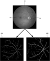
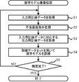
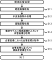
- FIG. 1 It is a block diagram which shows the schematic structure of the mathematical model construction apparatus 1, the fundus image processing apparatus 21, and the fundus imaging apparatus 11A, 11B. It is a figure which shows an example of the fundus image 30 and the blood vessel images 40A, 40B which show blood vessels included in the fundus image 30. It is a flowchart of the mathematical model construction process executed by the mathematical model construction apparatus 1. It is a flowchart of fundus image processing executed by fundus image processing apparatus 21. It is explanatory drawing for demonstrating an example of the method of acquiring the blood vessel image 60A, 60B from the fundus image 50 using a mathematical model.
- the horizontal axis is the diastolic blood pressure and the vertical axis is the blood vessel area.
- the horizontal axis is the measured value of baPWV
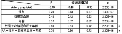
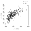
- the vertical axis is the blood vessel area. It is a table showing the correlation between PWV and at least one of the vascular area (AA) of an artery, the sex of a subject, systolic blood pressure, and age. It is a graph which plotted the predicted value of baPWV using the blood vessel area, sex, systolic blood pressure, and age of an artery, and the measured value of baPWV.
- the mathematical model construction device 1 constructs a mathematical model by training the mathematical model by a machine learning algorithm.
- the program that realizes the constructed mathematical model is stored in the storage device 24 of the fundus image processing device 21.
- the fundus image processing device 21 acquires an image (blood vessel image) showing at least one of an artery and a vein included in the fundus image.
- the fundus image processing device 21 acquires at least one area (blood vessel area) of arteries and veins included in the entire blood vessel image. Further, the fundus image processing device 21 indicates, based on the acquired blood vessel area, at least one of the estimated age of the subject from which the fundus image was taken, the degree of hypertension, and the degree of arteriosclerosis. Is output.
- the fundus image capturing devices 11A and 11B capture the fundus image of the eye to be inspected.
- a personal computer (hereinafter referred to as "PC") is used for the mathematical model construction device 1 of the present embodiment.
- the mathematical model construction device 1 shows at least one of the fundus image (hereinafter referred to as “training fundus image”) acquired from the fundus image capturing device 11A and the arteries and veins in the training fundus image.
- a mathematical model is constructed by training a mathematical model using a blood vessel image.
- the device that can function as the mathematical model construction device 1 is not limited to the PC.
- the fundus imaging device 11A may function as the mathematical model building device 1.
- the control units of the plurality of devices (for example, the CPU of the PC and the CPU 13A of the fundus imaging device 11A) may collaborate to construct a mathematical model.
- a PC is used for the fundus image processing device 21 of the present embodiment.
- the device that can function as the fundus image processing device 21 is not limited to the PC.
- the fundus image capturing device 11B or a server may function as the fundus image processing device 21.
- the fundus imaging device 11B may acquire the blood vessel image and the blood vessel area of the blood vessels included in the captured fundus image while capturing the fundus image. it can.
- the fundus imaging device 11B can also output the subject index based on the acquired blood vessel area.
- a mobile terminal such as a tablet terminal or a smartphone may function as the fundus image processing device 21.
- the control units of the plurality of devices (for example, the CPU of the PC and the CPU 13B of the fundus image capturing device 11B) may cooperate to perform various processes.
- a CPU is used as an example of a controller that performs various processes.
- a controller other than the CPU may be used for at least a part of various devices. For example, by adopting a GPU as a controller, the processing speed may be increased.
- the mathematical model construction device 1 will be described.
- the mathematical model construction device 1 is arranged, for example, in the fundus image processing device 21 or a manufacturer that provides the fundus image processing program to the user.
- the mathematical model building apparatus 1 includes a control unit 2 that performs various control processes and a communication I / F5.
- the control unit 2 includes a CPU 3 which is a controller that controls control, and a storage device 4 that can store programs, data, and the like.
- the storage device 4 stores a mathematical model construction program for executing a mathematical model construction process (see FIG. 3) described later.
- the communication I / F5 connects the mathematical model construction device 1 to other devices (for example, the fundus image capturing device 11A and the fundus image processing device 21).
- the mathematical model construction device 1 is connected to the operation unit 7 and the display device 8.
- the operation unit 7 is operated by the user in order for the user to input various instructions to the mathematical model construction device 1.
- the operation unit 7 for example, at least one of a keyboard, a mouse, a touch panel, and the like can be used.
- a microphone or the like for inputting various instructions may be used together with the operation unit 7 or instead of the operation unit 7.
- the display device 8 displays various images.
- various devices capable of displaying an image for example, at least one of a monitor, a display, a projector, and the like) can be used.
- the mathematical model construction device 1 can acquire data of a fundus image (hereinafter, may be simply referred to as a “fundus image”) from the fundus image capturing device 11A.
- the mathematical model construction device 1 may acquire data of the fundus image from the fundus image capturing device 11A by at least any one of, for example, wired communication, wireless communication, and a detachable storage medium (for example, a USB memory).
- the fundus image processing device 21 will be described.
- the fundus image processing device 21 is arranged in, for example, a facility (for example, a hospital or a health examination facility) for diagnosing or examining a subject.
- the fundus image processing device 21 includes a control unit 22 that performs various control processes and a communication I / F 25.
- the control unit 22 includes a CPU 23, which is a controller that controls control, and a storage device 24 that can store programs, data, and the like.
- the storage device 24 stores a fundus image processing program for executing fundus image processing (see FIG. 4), which will be described later.
- the fundus image processing program includes a program that realizes a mathematical model constructed by the mathematical model building apparatus 1.
- the communication I / F 25 connects the fundus image processing device 21 to other devices (for example, the fundus imaging device 11B and the mathematical model building device 1).
- the fundus image processing device 21 is connected to the operation unit 27 and the display device 28.
- various devices can be used in the same manner as the operation unit 7 and the display device 8 described above.
- the fundus image processing device 21 can acquire a fundus image from the fundus image capturing device 11B.
- the fundus image processing device 21 may acquire a fundus image from the fundus image capturing device 11B by at least one of wired communication, wireless communication, a detachable storage medium (for example, a USB memory), and the like. Further, the fundus image processing device 21 may acquire a program or the like for realizing the mathematical model constructed by the mathematical model building device 1 via communication or the like.
- the fundus imaging device 11 (11A, 11B) will be described.
- the fundus image capturing device 11 various devices for capturing an image of the fundus of the eye to be inspected can be used.
- the fundus image capturing device 11 used in the present embodiment is a fundus camera capable of capturing a two-dimensional color front image of the fundus using visible light. Therefore, the blood vessel image acquisition process and the blood vessel area acquisition process, which will be described later, are appropriately performed based on the color fundus image.
- a device other than the fundus camera for example, at least one of an OCT device, a laser scanning ophthalmoscope (SLO), etc.
- the fundus image may be a two-dimensional front image obtained by taking the fundus from the front side of the eye to be inspected, or may be a three-dimensional image of the fundus.
- the fundus image capturing device 11 includes a control unit 12 (12A, 12B) that performs various control processes, and a fundus imaging unit 16 (16A, 16B).
- the control unit 12 includes a CPU 13 (13A, 13B) which is a controller that controls control, and a storage device 14 (14A, 14B) capable of storing programs, data, and the like.
- the fundus image capturing unit 16 includes an optical member or the like for capturing a fundus image of the eye to be inspected.
- the fundus image capturing device 11 executes at least a part of the fundus image processing (see FIG. 4) described later, at least a part of the fundus image processing program for executing the fundus image processing is stored in the storage device 14. Needless to say.
- the mathematical model construction process executed by the mathematical model building apparatus 1 will be described with reference to FIGS. 2 and 3.
- the mathematical model construction process is executed by the CPU 3 according to the mathematical model construction program stored in the storage device 4.
- the mathematical model is trained by the training data set, so that a mathematical model that inputs the fundus image and outputs the blood vessel image is constructed.
- the training data set includes data on the input side (training data for input) and data on the output side (training data for output).
- the mathematical model can output blood vessel images based on various fundus images.
- the type of training data set used to train the mathematical model is determined by the type of fundus image input to the mathematical model. In the following, as an example, a case where a two-dimensional color front image taken by a fundus camera is input to a mathematical model as an input image to cause the mathematical model to output a blood vessel image will be described.
- FIG. 2 shows an example of input training data and output training data when a mathematical model outputs a blood vessel image using a two-dimensional color front image as an input image.
- the fundus image 30, which is a two-dimensional color front image captured by the fundus image capturing device (fundus camera in this embodiment) 11A, is used as input training data.
- the image region of the fundus image 30 used as input training data includes both the optic disc 31 and the macula 32 of the eye to be inspected.
- the blood vessel images 40A and 40B which are images showing at least one of an artery and a vein in the fundus image 30 which is used as input training data, are used as output training data.
- the blood vessel image 40A of the artery in the fundus image 30 and the blood vessel image 40B of the vein in the fundus image 30 are separately prepared.
- one blood vessel image showing both arteries and veins may be used as training data for output.
- only the blood vessel image of the artery is output to the mathematical model, only the blood vessel image 40A of the artery may be used as the output training data.
- only the venous blood vessel image is output to the mathematical model, only the venous blood vessel image 40B may be used as the output training data.
- a mathematical model for preprocessing for outputting a blood vessel image (hereinafter, referred to as “base blood vessel image”) as a base for generating output training data is constructed in advance.
- the mathematical model for preprocessing is trained using the fundus image as training data for input and the base blood vessel image manually created by the operator as training data for output.
- the operator operates the operation unit 7 with reference to the fundus image captured by the fundus image capturing device 11A, and mathematically gives instructions for generating a base blood vessel image. Input to the model building device 1.
- the CPU 3 of the mathematical model construction device 1 generates a base blood vessel image in response to an instruction input by the operator, and trains the mathematical model using the fundus image and the base blood vessel image to create a mathematical model for preprocessing. To construct. By inputting the fundus image 30 into the mathematical model for preprocessing, the CPU 3 outputs the base blood vessel image and displays it on the display device 8. The operator operates the operation unit 7 while referring to the displayed base blood vessel image, and inputs a correction instruction of the base blood vessel image to the mathematical model construction device 1. The CPU 3 modifies the base blood vessel image according to the instruction input by the operator to generate the blood vessel images 40A and 40B. As a result, blood vessel images 40A and 40B that represent blood vessels more accurately than the base blood vessel image are generated.
- the CPU 3 may directly generate the blood vessel images 40A and 40B in response to the instructions input by the operator without using the mathematical model for preprocessing.
- the mathematical model construction process will be described with reference to FIG.
- the CPU 3 acquires the fundus image 30 captured by the fundus image capturing device 11A as input training data (S1).
- the data of the fundus image 30 is generated by the fundus imaging device 11A and then acquired by the mathematical model construction device 1.
- the CPU 3 acquires a signal (for example, a signal received by the light receiving element) that is a basis for generating the fundus image 30 from the fundus image capturing apparatus 11A, and generates the fundus image 30 based on the acquired signal.
- the data of the fundus image 30 may be acquired.
- the CPU 3 executes the defective image exclusion process (S2).
- the defective image exclusion process the CPU 3 excludes the fundus image 30 whose focus match degree at the time of shooting does not meet the standard from the input training data used for training the mathematical model.
- the area of the blood vessels reflected in the fundus image 30 is larger than the actual blood vessel area. Therefore, by executing the defective image exclusion process, the accuracy of the blood vessel image output by the trained mathematical model is improved.
- the CPU 3 omits the processes S3 to S5 described later.
- the CPU 3 executes edge detection by image processing on the fundus image 30 acquired in S1, and excludes the fundus image 30 whose edge sharpness is equal to or less than the threshold value from the input training data. To do. In the fundus image 30 having a low degree of focus matching, the edges of the image become unclear. Therefore, by excluding the fundus image 30 whose edge sharpness is equal to or less than the threshold value, only the fundus image 30 having a high degree of focus matching is appropriately used as input training data.
- the CPU 3 may use the fundus image 30 having the highest degree of focus matching among the plurality of fundus images 30 taken while changing the focus on the fundus of the same eye to be inspected as input training data. .. Even in this case, the accuracy of the blood vessel image output by the trained mathematical model is appropriately improved.
- a defective fundus image 30 caused by at least one of poor imaging, opacity of the intermediate translucent body of the eye to be inspected, cataract, occurrence of artifacts, etc. It may be excluded from the input training data used to train the model. In this case, the accuracy of the blood vessel image output by the trained mathematical model is further improved.
- the CPU 3 acquires the blood vessel images 40A and 40B (output training data) corresponding to the fundus image 30 (input training data) acquired in S1 (S3).
- An example of a method for generating blood vessel images 40A and 40B based on the fundus image 30 is as described above.
- the CPU 3 executes the training of the mathematical model using the training data set by the machine learning algorithm (S4).
- the machine learning algorithm for example, a neural network, a random forest, a boosting, a support vector machine (SVM), and the like are generally known.
- Neural networks are a method that mimics the behavior of biological nerve cell networks.
- Neural networks include, for example, feed-forward (forward propagation) neural networks, RBF networks (radial basis functions), spiking neural networks, convolutional neural networks, recursive neural networks (recurrent neural networks, feedback neural networks, etc.), and probabilities.
- Neural networks Boltzmann machines, Basian networks, etc.).
- Random forest is a method of generating a large number of decision trees by learning based on randomly sampled training data.
- the branches of a plurality of decision trees learned in advance as a discriminator are traced, and the average (or majority vote) of the results obtained from each decision tree is taken.
- Boosting is a method of generating a strong classifier by combining multiple weak classifiers.
- a strong classifier is constructed by sequentially learning simple and weak classifiers.
- SVM is a method of constructing a two-class pattern classifier using a linear input element.
- the SVM learns the parameters of the linear input element based on, for example, the criterion (hyperplane separation theorem) of obtaining the margin maximizing hyperplane that maximizes the distance from each data point from the training data.
- a mathematical model refers to, for example, a data structure for predicting the relationship between input data and output data.
- Mathematical models are constructed by training with training datasets.
- the training data set is a set of training data for input and training data for output.
- training updates the correlation data (eg, weights) for each input and output.
- a multi-layer neural network is used as a machine learning algorithm.
- a neural network includes an input layer for inputting data, an output layer for generating the data to be predicted, and one or more hidden layers between the input layer and the output layer.
- a plurality of nodes also called units
- a convolutional neural network (CNN) which is a kind of multi-layer neural network
- CNN convolutional neural network
- other machine learning algorithms may be used.
- GAN hostile generative network
- GAN hostile generative network
- the fundus image processing of the present embodiment will be described with reference to FIGS. 4 and 5.
- blood vessel images 60A and 60B showing blood vessels included in the fundus image 50 (see FIG. 5) are acquired by using a mathematical model trained by a machine learning algorithm.
- the blood vessel area is acquired based on the blood vessel images 60A and 60B.
- a subject index indicating at least one of the estimated age of the subject, the degree of hypertension, and the degree of arteriosclerosis is output.
- the fundus image processing illustrated in FIG. 4 is executed by the CPU 23 of the fundus image processing device 21 according to the fundus image processing program stored in the storage device 24.
- the CPU 23 acquires the fundus image 50 (see FIG. 5), which is a two-dimensional color front image, taken by the fundus image capturing device (fundus camera in this embodiment) 11B (S11).
- the fundus image 50 acquired in S1 is captured by the same type of image (that is, the same type of fundus imaging device) as the fundus image 30 (see FIG. 2) used as input training data when training the mathematical model. Image).
- the image region of the fundus image 50 acquired in S1 includes both the optic nerve head 51 and the macula 52 of the eye to be inspected.
- the CPU 23 executes the defective image exclusion process (S12).
- the defective image exclusion process the CPU 23 excludes the fundus image 50 whose focus matching degree at the time of shooting does not satisfy the standard from the fundus image 50 to be input to the mathematical model.
- the area of the blood vessels reflected in the fundus image 50 is larger than the actual blood vessel area. Therefore, by executing the defective image exclusion process, the accuracy of the blood vessel images 60A and 60B output by the mathematical model in S14, which will be described later, is improved.
- the CPU 23 omits the processes of S13 to S16 described later.
- the specific method of the defective image exclusion process (S12) can be appropriately selected.
- the CPU 23 executes edge detection on the fundus image 50 acquired in S11 in the same manner as in S2 of the mathematical model construction process (see FIG. 3) described above, and the edge sharpness is improved.
- the fundus image 50 that is equal to or less than the threshold value is excluded from the fundus image 50 to be input to the mathematical model.
- the CPU 23 uses the fundus image 50 having the highest degree of focus matching as the fundus image 50 to be input to the mathematical model among the plurality of fundus images 50 captured while changing the focus on the fundus of the same eye to be inspected. You may.
- a defective fundus image 50 caused by at least one of poor imaging, opacity of the intermediate translucent body of the eye to be inspected, cataract, occurrence of artifacts, etc. It may be excluded from the target fundus image 50 to be input to the model.
- the CPU 23 executes the area adjustment process (S13).
- the area adjustment process the CPU 23 adjusts the area of the image area to be input to the mathematical model in the image area of the fundus image 50 acquired in S11 to bring the area closer to the target value.
- the area of the region for acquiring the blood vessel area is made uniform, so that the influence of individual differences in the eye to be inspected and differences in the imaging method is suppressed.
- the image area is adjusted so that the image area of the fundus image 50 input to the mathematical model includes both the optic nerve head 51 and the macula 52.
- the CPU 23 acquires information on the axial length of the eye to be imaged, and sets the area of the image region to be input to the mathematical model in the image region of the fundus image 50 as the axial length. Uniformize accordingly.
- the CPU 23 inputs to the mathematical model a region of the fundus blood vessels reflected in the fundus image 50 including the fundus blood vessels from the optic disc 51 side to the Nth (N is a predetermined natural number) bifurcation point. It may be an area.
- the CPU 23 inputs the fundus image 50 into the mathematical model trained by the machine learning algorithm to acquire the blood vessel images 60A and 60B showing at least one of the arteries and veins included in the fundus image 50 (S14). ..
- the blood vessel image 60A of the artery in the fundus image 50 and the blood vessel image 60B of the vein in the fundus image 50 are separately acquired by a mathematical model.
- one vascular image showing both arteries and veins may be output by a mathematical model.
- the mathematical model can also output only one of the arterial blood vessel image 60A and the vein blood vessel image 60B.
- the CPU 23 acquires the blood vessel area, which is the area of the blood vessels (in the present embodiment, each of the arteries and veins) included in the entire blood vessel images 60A and 60B acquired in S14 (S15).
- the method of acquiring the blood vessel area from the blood vessel images 60A and 60B can also be appropriately selected.
- the number of pixels constituting the blood vessel in the blood vessel images 60A and 60B is acquired as the blood vessel area.
- a mathematical model that inputs blood vessel images 60A and 60B and outputs the blood vessel area may be used.
- the mathematical model may be trained in advance using the blood vessel image as input training data and the blood vessel area as output training data.
- the CPU 23 may adjust the area of the image area of the blood vessel images 60A and 60B for which the blood vessel area is acquired in S15, instead of adjusting the area of the image area of the fundus image 50 input to the mathematical model in S13.
- the same method as that described in S13 may be adopted as the method for adjusting the area of the blood vessel images 60A and 60B.
- the CPU 23 outputs a subject index indicating at least one of the estimated age of the subject from which the fundus image 50 was taken, the degree of hypertension, and the degree of arteriosclerosis, based on the blood vessel area acquired in S15. (S16).
- the data shown in FIGS. 6 to 10 include the number of subjects: 5605 (3608 males, 1997 females), the number of eyes to be examined: 10586 eyes, the number of fundus images 50: 10964, and the average age of the subjects: The data are about 49.4 ⁇ 9.6 years old, the average systolic blood pressure of the subject: 117.6 ⁇ 16.1 mmHg, and the average diastolic blood pressure of the subject: 74.0 ⁇ 11.0 mmHg.
- 11 to 13 include the number of subjects: 372, the number of eyes to be examined: 696 eyes (542 eyes to be examined for men, 154 eyes to be examined for women), and the number of fundus images 50: 696. Data on the average age of the subjects: 53.7 ⁇ 10.0 years, the average systolic blood pressure of the subjects: 122.1 ⁇ 15.0 mmHg, and the average diastolic blood pressure: 76.1 ⁇ 10.3 mmHg. ..
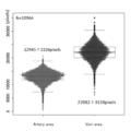
- the distribution and area ratio of the arterial blood vessel area (Artery area) and the venous blood vessel area (Vein area) will be described.
- the vascular area of the artery tends to be smaller than the vascular area of the vein.
- Arterial blood vessel area: venous blood vessel area about 1: 1.7.
- the ratio of the blood vessel area of the artery was about 2.6% and the ratio of the blood vessel area of the vein was about 4.5% with respect to the total area of the fundus image 50.
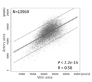
- FIGS. 7-11 The correlation between the vascular area of the artery and the vascular area of the vein will be described with reference to FIG. 7.
- the two lines diagonally crossing the center of the graph in close proximity indicate a 95% confidence interval.
- the two lines diagonally crossing the outside of the 95% confidence interval indicate the 95% prediction interval.
- FIG. 7 it can be seen that there is a correlation between the vascular area of the artery and the vascular area of the vein.
- the correlation coefficient R between the vascular area of the artery and the vascular area of the vein was 0.58, and there was a moderate positive correlation.
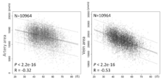
- the correlation coefficient between the vascular area of the artery and the age of the subject was -0.32.
- the correlation coefficient between the vascular area of the vein and the age of the subject was -0.53. That is, both the arterial vascular area and the venous vascular area had a negative correlation with age, but the venous vascular area was more correlated with age than the arterial vascular area. It turns out to be strong.
- a calculation formula or a table for determining the estimated age of the subject from the venous blood vessel area based on the relationship between the venous blood vessel area and the age obtained for each of the plurality of subjects, etc. has been created.
- the CPU 23 outputs a subject index indicating the estimated age of the subject by applying the blood vessel area of the vein acquired in S15 to a calculation formula or a table or the like.
- a calculation formula or a table for determining the estimated age of a subject from the blood vessel area of a vein and the blood vessel area of an artery may be created based on data on a plurality of subjects.
- the CPU 23 may output a subject index indicating the estimated age of the subject by applying the blood vessel areas of the veins and arteries acquired in S15 to a calculation formula or a table or the like.
- a subject index indicating the estimated age of the subject may be output based on the ratio of the blood vessel area of the artery to the blood vessel area of the vein.
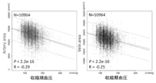
- the correlation between the vascular area of the artery and the systolic blood pressure and the correlation between the venous vascular area and the systolic blood pressure will be described with reference to FIG.
- the correlation coefficient between the vascular area of the artery and the systolic blood pressure of the subject was -0.29.
- the correlation coefficient between the venous blood vessel area and the systolic blood pressure of the subject was -0.25. That is, both the vascular area of the artery and the vascular area of the venous were negatively correlated with the systolic blood pressure, but the vascular area of the artery was more related to the systolic blood pressure than the vascular area of the venous. It can be seen that the correlation is strong.
- the subject based on the relationship between the arterial vessel area, age, and systolic blood pressure obtained for each of the plurality of subjects, the subject is based on the arterial vessel area and the subject's age.
- a formula or table for calculating the index of systolic blood pressure has been created.
- the CPU 23 outputs a subject index of systolic blood pressure by applying the age of the subject and the blood vessel area of the artery acquired in S15 to a calculation formula or a table or the like.
- the age of the subject used when outputting the subject index may be input by the user, or the estimated age described above may be used.
- a calculation formula or a table for determining a subject index of systolic blood pressure from the venous vessel area, the artery vessel area, and age may be created based on data on a plurality of subjects. ..
- the CPU 23 may output a subject index of systolic blood pressure by applying the venous blood vessel area, the arterial blood vessel area, and the age of the subject to a calculation formula, a table, or the like.
- the ratio of the vascular area of the artery to the vascular area of the vein may be used when outputting the subject index of systolic blood pressure.
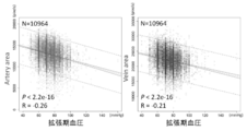
- the correlation between the vascular area of the artery and the diastolic blood pressure and the correlation between the vascular area of the vein and the diastolic blood pressure will be described.
- the correlation coefficient between the vascular area of the artery and the diastolic blood pressure of the subject was -0.26.
- the correlation coefficient between the venous blood vessel area and the diastolic blood pressure of the subject was -0.21. That is, both the arterial vascular area and the venous vascular area had a negative correlation with the diastolic blood pressure, but the arterial vascular area was more related to the diastolic blood pressure than the venous vascular area. It can be seen that the correlation is strong.
- the subject based on the relationship between the arterial vessel area, age, and diastolic blood pressure obtained for each of the plurality of subjects, the subject is based on the arterial vessel area and the subject's age.
- a formula or table for calculating the index of diastolic blood pressure has been created.
- the CPU 23 outputs a subject index of diastolic blood pressure by applying the age of the subject and the blood vessel area of the artery acquired in S15 to a calculation formula or a table or the like.
- the age of the subject used when outputting the subject index may be input by the user, or the estimated age described above may be used.
- a formula or table for determining a subject index of diastolic blood pressure from the venous vessel area, the artery vessel area, and age may be created based on data on a plurality of subjects. ..
- the CPU 23 may output the subject index of diastolic blood pressure by applying the venous blood vessel area, the arterial blood vessel area, and the age of the subject to a calculation formula, a table, or the like.
- the ratio of the vascular area of the artery to the vascular area of the vein may be used when outputting the subject index of diastolic blood pressure.
- At least one of the systolic blood pressure subject index and the diastolic blood pressure subject index may be output as it is as an index indicating the degree of hypertension of the subject.
- an index indicating the degree of hypertension of the subject (for example, the estimated degree of hypertension is graded) based on at least one of the subject index of systolic blood pressure and the subject index of diastolic blood pressure. An index, etc.) may be calculated and output.
- PWV Pulse wave velocity
- PWV Pulse wave velocity
- the correlation coefficient between the vascular area of the artery and baPWV was ⁇ 0.40.
- the correlation coefficient between the venous blood vessel area and baPWV was ⁇ 0.36. That is, both the arterial vascular area and the venous vascular area had a negative correlation with baPWV, but the arterial vascular area was more correlated with baPWV than the venous vascular area. It turns out to be strong.
- the correlation between at least one of the arterial vessel area (AA), the subject's gender, systolic blood pressure, and age and PWV will be described. As shown in FIG. 12, it can be seen that PWV correlates with each of gender, systolic blood pressure, and age, in addition to the vascular area of the artery. In addition, in the column of * in FIG. 12, the correlation by the predicted value is shown.
- the correlation between the predicted value of baPWV using the blood vessel area, sex, systolic blood pressure, and age of the artery and the measured value of baPWV will be described.
- the predicted value of baPWV using the vascular area, sex, systolic blood pressure, and age of the artery and the measured value of baPWV showed a significant positive correlation.
- the arterial blood vessels are obtained based on the arterial blood vessel area, sex, systolic blood pressure, and age obtained for each of the plurality of subjects and the measured values of PWV (for example, baPWV).
- PWV for example, baPWV
- a calculation formula or table for calculating the PWV index (predicted value) of the subject from the area, gender, systolic blood pressure, and age has been created.
- the CPU 23 applies the blood vessel area of the artery acquired in S15 and information such as the age of the subject to a calculation formula or a table or the like to obtain a predicted value of PWV, which is an example of an index indicating the degree of arteriosclerosis. Output.
- the fundus image processing device 21 of the present embodiment can appropriately output an index (predicted value of PWV) indicating the degree of arteriosclerosis based on the fundus image 50 that can be captured in a short time.
- an index indicating the degree of arteriosclerosis may be output by using the vascular area of a vein in addition to the vascular area of an artery or instead of the vascular area of an artery. Further, by using the ratio of the blood vessel area of the artery to the blood vessel area of the vein, an index indicating the degree of arteriosclerosis may be output. It is also possible to output an index indicating the degree of arteriosclerosis without using at least any information other than the blood vessel area (gender, blood pressure, and age). At least one of the ratio of the arterial vascular area, the venous vascular area, and the arteriovenous vascular area may be output as an index indicating the degree of arteriosclerosis.
- the technology disclosed in the above embodiment is only an example. Therefore, it is possible to modify the techniques exemplified in the above embodiments.
- the process of outputting the subject index based on the blood vessel area may be omitted, and only the blood vessel area acquired in S15 may be output. Even in this case, the user (for example, a doctor or the like) can easily and appropriately diagnose the subject based on the output blood vessel area information.
- the process of acquiring the fundus image in S11 of FIG. 4 is an example of the “fundus image acquisition step”.
- the process of acquiring a blood vessel image in S14 of FIG. 4 is an example of the “blood vessel image acquisition step”.
- the process of acquiring the blood vessel area in S15 of FIG. 4 is an example of the “blood vessel area acquisition step”.
- the process of outputting the subject index in S16 of FIG. 4 is an example of the “index output step”.
- Fundus image capturing device 16 Fundus imaging unit 21 Fundus image processing device 23 CPU 24 Storage device 30 Fundus image 40A, 40B Blood vessel image 50 Fundus image 60A, 60B Blood vessel image
Landscapes
- Health & Medical Sciences (AREA)
- Engineering & Computer Science (AREA)
- Medical Informatics (AREA)
- Life Sciences & Earth Sciences (AREA)
- General Health & Medical Sciences (AREA)
- Public Health (AREA)
- Biomedical Technology (AREA)
- Nuclear Medicine, Radiotherapy & Molecular Imaging (AREA)
- Radiology & Medical Imaging (AREA)
- Physics & Mathematics (AREA)
- Primary Health Care (AREA)
- Epidemiology (AREA)
- Biophysics (AREA)
- Animal Behavior & Ethology (AREA)
- Ophthalmology & Optometry (AREA)
- Veterinary Medicine (AREA)
- Heart & Thoracic Surgery (AREA)
- Molecular Biology (AREA)
- Surgery (AREA)
- Data Mining & Analysis (AREA)
- General Physics & Mathematics (AREA)
- Theoretical Computer Science (AREA)
- Computer Vision & Pattern Recognition (AREA)
- Quality & Reliability (AREA)
- Databases & Information Systems (AREA)
- Pathology (AREA)
- Vascular Medicine (AREA)
- Signal Processing (AREA)
- Hematology (AREA)
- Eye Examination Apparatus (AREA)
Abstract
眼底画像処理装置の制御部は、眼底画像撮影部によって撮影された眼底画像50を取得する。制御部は、機械学習アルゴリズムによって訓練された数学モデルに眼底画像50を入力することで、眼底画像50に含まれる動脈および静脈の少なくともいずれかを示す血管画像60A,60Bを取得する。制御部は、血管画像60A,60B全体に含まれる動脈および静脈の少なくともいずれかの面積である血管面積を取得する。
Description
本開示は、被検眼の眼底画像を処理する眼底画像処理装置、および、眼底画像処理装置において実行される眼底画像処理プログラムに関する。
眼底を観察することで、生体の血管の状態を非侵襲で把握することが可能である。従来、眼底画像から得られた血管(動脈および静脈の少なくともいずれか)に関する情報が、種々の診断等に利用されている。例えば、特許文献1が開示する動静脈径比の計測方法では、視神経乳頭(以下、単に「乳頭」という)の中心を基準に、半径が異なる2つの同心円で囲まれる領域Rnが複数設定される。設定された領域Rn内で、複数の血管が抽出される。抽出された複数の血管の中から、血管間の距離が小さい2本の血管が血管対として選択される。選択された血管対から動静脈径比が算出される。
特許文献1に記載の方法では、乳頭の周囲における一部の領域内の血管のみが参照されるので、取得される情報の信頼性および正確性が低い場合も有り得る。また、血管以外の組織も含む眼底画像から情報を取得することも考えられる。しかし、この場合には、眼底における疾患、被検眼の混濁、および画像のアーチファクト等が、取得される情報に悪影響を与えやすくなる。従って、従来の技術では、生体の血管に基づく情報を眼底画像から適切に取得することは困難であった。
本開示の典型的な目的は、生体の血管に基づく情報を眼底画像から適切に取得することが可能な眼底画像処理装置および眼底画像処理プログラムを提供することである。
本開示における典型的な実施形態が提供する眼底画像処理装置は、被検眼の眼底画像を処理する眼底画像処理装置であって、前記眼底画像処理装置の制御部は、眼底画像撮影部によって撮影された眼底画像を取得する眼底画像取得ステップと、機械学習アルゴリズムによって訓練された数学モデルに前記眼底画像を入力することで、前記眼底画像に含まれる動脈および静脈の少なくともいずれかを示す血管画像を取得する血管画像取得ステップと、前記血管画像取得ステップにおいて取得された前記血管画像全体に含まれる前記動脈および前記静脈の少なくともいずれかの面積である血管面積を取得する血管面積取得ステップと、を実行する。
本開示における典型的な実施形態が提供する眼底画像処理プログラムは、被検眼の眼底画像を処理する眼底画像処理装置によって実行される眼底画像処理プログラムであって、前記眼底画像処理プログラムが前記眼底画像処理装置の制御部によって実行されることで、眼底画像撮影部によって撮影された眼底画像を取得する眼底画像取得ステップと、機械学習アルゴリズムによって訓練された数学モデルに前記眼底画像を入力することで、前記眼底画像に含まれる動脈および静脈の少なくともいずれかを示す血管画像を取得する血管画像取得ステップと、前記血管画像取得ステップにおいて取得された前記血管画像全体に含まれる前記動脈および前記静脈の少なくともいずれかの面積である血管面積を取得する血管面積取得ステップと、を前記眼底画像処理装置に実行させる。
本開示に係る眼底画像処理装置および眼底画像処理プログラムによると、生体の血管に基づく情報が眼底画像から適切に取得される。
本開示で例示する眼底画像処理装置の制御部は、眼底画像取得ステップ、血管画像取得ステップ、および血管面積取得ステップを実行する。眼底画像取得ステップでは、制御部は、機械学習アルゴリズムによって訓練された数学モデルに眼底画像を入力することで、眼底画像に含まれる動脈および静脈の少なくともいずれかを示す血管画像を取得する。血管面積取得ステップでは、制御部は、血管画像取得ステップにおいて取得された血管画像全体に含まれる動脈および静脈の少なくともいずれかの面積である血管面積を取得する。
本開示で例示する眼底画像処理装置によると、眼底における一部の領域(例えば、乳頭の周囲の領域等)の血管のみが参照される場合とは異なり、眼底における広い領域内の血管の面積が取得される。従って、信頼性および正確性が高い情報が、眼底血管に基づいて取得され易い。また、血管以外の組織も含む眼底画像全体から情報を取得する場合とは異なり、眼底画像に基づいて取得される血管画像から血管面積が取得される。従って、眼底画像内の疾患、混濁、およびアーチファクト等の影響が生じにくい。よって、生体の血管に基づく情報が、眼底画像から適切に取得される。
数学モデルに入力される眼底画像には、眼底血管が写る種々の眼底画像を使用することができる。例えば、眼底カメラによって眼底を正面から撮影した二次元の眼底画像が、数学モデルに入力されてもよい。この場合、カラーの眼底画像に基づいて血管画像を取得することも可能である。また、OCT(Optical Cohelence Tomography)装置によって撮影された眼底の二次元OCTアンジオ画像が数学モデルに入力されてもよい。OCTアンジオ画像は、例えば、同一位置に関して異なる時間に取得された少なくとも2つのOCT信号が処理されることで取得されるモーションコントラスト画像であってもよい。OCT装置は、他の種類の眼底画像よりも解像度が高いOCTアンジオ画像を撮影することができる。従って、OCTアンジオ画像に基づいて血管画像を取得することで、生体の血管に基づく情報の正確性および信頼性がさらに向上する。また、レーザ走査型検眼鏡(SLO)によって眼底を正面から撮影した二次元の眼底画像が、数学モデルに入力されてもよい。また、OCT装置によって撮影された眼底の二次元正面画像、三次元断層画像等が、数学モデルに入力されてもよい。
制御部は、血管面積取得ステップにおいて取得された血管面積に基づいて、眼底画像が撮影された被検者の推定年齢、高血圧の程度、および動脈硬化の程度の少なくともいずれかの指標(以下、「被検者指標」という場合もある)を出力する指標出力ステップを実行してもよい。本願の発明者は、被検者の眼底における血管面積と、被検者の年齢および血圧に相関があることを見出した。また、眼底血管には、被検者の高血圧および高脂血症等を原因とする動脈硬化の状態が反映される。従って、血管面積取得ステップにおいて取得された血管面積を利用することで、熟練した医師による判断等を介さなくても、被検者の推定年齢、高血圧の程度、および動脈硬化の程度の少なくともいずれかを示す指標が適切に出力される。
ただし、眼底画像処理装置は、被検者指標を出力せずに、取得した血管面積のみを出力してもよい。この場合でも、ユーザは、出力された血管面積の情報に基づいて、被検者の診断等を容易且つ適切に行うことができる。
数学モデルに入力される眼底画像の画像領域には、被検眼の視神経乳頭および黄斑が共に含まれていてもよい。この場合には、眼底におけるより広い領域の血管の情報が参照されるので、狭い領域(例えば、乳頭近傍の領域のみ)の血管の情報が参照される場合に比べて、取得される情報(例えば、血管面積および被検者指標の少なくともいずれか)の信頼性および正確性がさらに向上する。
制御部は、血管面積取得ステップにおいて血管面積を取得する画像領域の面積を調整して目標値に近づける面積調整ステップをさらに実行してもよい。この場合、血管面積を取得する領域の面積が均一化されるので、被検眼の個体差および撮影方法の差等の影響が抑制される。よって、取得される情報の信頼性および正確性がさらに向上する。
面積調整ステップを実行する際の具体的な方法は適宜選択できる。例えば、撮影画角が一定である場合でも、撮影対象となる被検眼の眼軸長に応じて、撮影される眼底上の領域の面積は変化する。従って、制御部は、撮影対象とした被検眼の眼軸長に応じて、血管面積を取得する眼底画像または血管画像の領域の面積を調整してもよい。また、眼底血管は、乳頭から遠ざかる過程で複数回分岐する。制御部は、眼底血管のうち、N番目(Nは予め定められた自然数)の分岐点までの眼底血管が含まれる領域を、血管面積を取得する眼底画像または血管画像の領域として調整してもよい。また、制御部は、一定の画角で撮影された眼科画像を数学モデルに入力することで、血管面積を取得する眼底上の領域の面積を調整してもよい。この場合でも、異なる画角で撮影された眼科画像を用いる場合に比べて、取得される情報の信頼性および正確性は向上する。なお、面積調整ステップでは、数学モデルに入力される眼科画像の領域の面積が調整されてもよいし、血管面積が取得される血管画像の領域の面積が調整されてもよい。
制御部は、撮影時のフォーカスの合致度が基準を満たさない眼科画像を、血管画像取得ステップにおいて数学モデルに入力する対象とする眼科画像から除外する除外ステップをさらに実行してもよい。フォーカスの合致度が基準を満たさない眼科画像では、実際の血管面積よりも、眼科画像に写る血管面積が大きくなる。従って、除外ステップを実行することで、取得される情報の信頼性および正確性がさらに向上する。
除外ステップを実行する際の具体的な方法も、適宜選択できる。例えば、フォーカスの合致度が低い眼科画像では、画像のエッジが不鮮明となる。従って、制御部は、画像処理等によって眼科画像のエッジ検出を実行し、エッジの鮮明度が閾値以下である眼科画像を除外してもよい。
また、制御部は、同一の被検眼の眼底についてフォーカスを変化させながら撮影された複数枚の眼科画像のうち、フォーカスの合致度が最も高い眼科画像を、血管画像取得ステップにおいて数学モデルに入力してもよい。この場合でも、取得される情報の信頼性および正確性は適切に向上する。
数学モデルは、過去に撮影された被検眼の眼底画像を入力用訓練データとし、且つ、入力用訓練データの眼底画像における動脈および静脈の少なくともいずれかを示す血管画像を出力用訓練データとして訓練されていてもよい。この場合、例えば、まず血管を検出してその後に血管を動脈と静脈に分類する方法等に比べて、簡易な処理で適切に血管画像が取得される。
数学モデルを訓練するために用いられる入力用訓練データと出力用訓練データの態様は、適宜選択できる。例えば、前述したように、眼底カメラによって撮影された眼底の二次元カラー正面画像が、入力用訓練データとされてもよい。また、SLOによって撮影された眼底の二次元正面画像が、入力用訓練データとされてもよい。また、作業者が、眼底画像撮影部によって撮影された眼底画像を参照して手動で作成した血管画像が、出力用訓練データとされてもよい。また、眼底画像を入力して血管画像を出力する仮の数学モデルに眼底画像が入力されることで、仮の血管画像が取得された後、取得された仮の血管画像が作業者によって修正されることで、入力用訓練データが取得されてもよい。この場合、数学モデルがより適切に訓練され、取得される血管画像の精度が向上する。
(装置構成)
以下、本開示における典型的な実施形態の1つについて、図面を参照して説明する。図1に示すように、本実施形態では、数学モデル構築装置1、眼底画像処理装置21、および眼底画像撮影装置11A,11Bが用いられる。数学モデル構築装置1は、機械学習アルゴリズムによって数学モデルを訓練させることで、数学モデルを構築する。構築された数学モデルを実現するプログラムは、眼底画像処理装置21の記憶装置24に記憶される。眼底画像処理装置21は、数学モデルに眼底画像を入力することで、眼底画像に含まれる動脈および静脈の少なくともいずれかを示す画像(血管画像)を取得する。また、眼底画像処理装置21は、血管画像全体に含まれる動脈および静脈の少なくともいずれかの面積(血管面積)を取得する。さらに、眼底画像処理装置21は、取得された血管面積に基づいて、眼底画像が撮影された被検者の推定年齢、高血圧の程度、および動脈硬化の程度の少なくともいずれかを示す被検者指標を出力する。眼底画像撮影装置11A,11Bは、被検眼の眼底画像を撮影する。
以下、本開示における典型的な実施形態の1つについて、図面を参照して説明する。図1に示すように、本実施形態では、数学モデル構築装置1、眼底画像処理装置21、および眼底画像撮影装置11A,11Bが用いられる。数学モデル構築装置1は、機械学習アルゴリズムによって数学モデルを訓練させることで、数学モデルを構築する。構築された数学モデルを実現するプログラムは、眼底画像処理装置21の記憶装置24に記憶される。眼底画像処理装置21は、数学モデルに眼底画像を入力することで、眼底画像に含まれる動脈および静脈の少なくともいずれかを示す画像(血管画像)を取得する。また、眼底画像処理装置21は、血管画像全体に含まれる動脈および静脈の少なくともいずれかの面積(血管面積)を取得する。さらに、眼底画像処理装置21は、取得された血管面積に基づいて、眼底画像が撮影された被検者の推定年齢、高血圧の程度、および動脈硬化の程度の少なくともいずれかを示す被検者指標を出力する。眼底画像撮影装置11A,11Bは、被検眼の眼底画像を撮影する。
一例として、本実施形態の数学モデル構築装置1にはパーソナルコンピュータ(以下、「PC」という)が用いられる。詳細は後述するが、数学モデル構築装置1は、眼底画像撮影装置11Aから取得した眼底画像(以下、「訓練用眼底画像」という)と、訓練用眼底画像における動脈および静脈の少なくともいずれかを示す血管画像を利用して数学モデルを訓練させることで、数学モデルを構築する。しかし、数学モデル構築装置1として機能できるデバイスは、PCに限定されない。例えば、眼底画像撮影装置11Aが数学モデル構築装置1として機能してもよい。また、複数のデバイスの制御部(例えば、PCのCPUと、眼底画像撮影装置11AのCPU13A)が、協働して数学モデルを構築してもよい。
また、本実施形態の眼底画像処理装置21にはPCが用いられる。しかし、眼底画像処理装置21として機能できるデバイスも、PCに限定されない。例えば、眼底画像撮影装置11Bまたはサーバ等が、眼底画像処理装置21として機能してもよい。眼底画像撮影装置11Bが眼底画像処理装置21として機能する場合、眼底画像撮影装置11Bは、眼底画像を撮影しつつ、撮影した眼底画像に含まれる血管についての血管画像および血管面積を取得することができる。また、眼底画像撮影装置11Bは、取得した血管面積に基づいて被検者指標を出力することもできる。また、タブレット端末またはスマートフォン等の携帯端末が、眼底画像処理装置21として機能してもよい。複数のデバイスの制御部(例えば、PCのCPUと、眼底画像撮影装置11BのCPU13B)が、協働して各種処理を行ってもよい。
また、本実施形態では、各種処理を行うコントローラの一例としてCPUが用いられる場合について例示する。しかし、各種デバイスの少なくとも一部に、CPU以外のコントローラが用いられてもよいことは言うまでもない。例えば、コントローラとしてGPUを採用することで、処理の高速化を図ってもよい。
数学モデル構築装置1について説明する。数学モデル構築装置1は、例えば、眼底画像処理装置21または眼底画像処理プログラムをユーザに提供するメーカー等に配置される。数学モデル構築装置1は、各種制御処理を行う制御ユニット2と、通信I/F5を備える。制御ユニット2は、制御を司るコントローラであるCPU3と、プログラムおよびデータ等を記憶することが可能な記憶装置4を備える。記憶装置4には、後述する数学モデル構築処理(図3参照)を実行するための数学モデル構築プログラムが記憶されている。また、通信I/F5は、数学モデル構築装置1を他のデバイス(例えば、眼底画像撮影装置11Aおよび眼底画像処理装置21等)と接続する。
数学モデル構築装置1は、操作部7および表示装置8に接続されている。操作部7は、ユーザが各種指示を数学モデル構築装置1に入力するために、ユーザによって操作される。操作部7には、例えば、キーボード、マウス、タッチパネル等の少なくともいずれかを使用できる。なお、操作部7と共に、または操作部7に代えて、各種指示を入力するためのマイク等が使用されてもよい。表示装置8は、各種画像を表示する。表示装置8には、画像を表示可能な種々のデバイス(例えば、モニタ、ディスプレイ、プロジェクタ等の少なくともいずれか)を使用できる。
数学モデル構築装置1は、眼底画像撮影装置11Aから眼底画像のデータ(以下、単に「眼底画像」という場合もある)を取得することができる。数学モデル構築装置1は、例えば、有線通信、無線通信、着脱可能な記憶媒体(例えばUSBメモリ)等の少なくともいずれかによって、眼底画像撮影装置11Aから眼底画像のデータを取得してもよい。
眼底画像処理装置21について説明する。眼底画像処理装置21は、例えば、被検者の診断または検査等を行う施設(例えば、病院または健康診断施設等)に配置される。眼底画像処理装置21は、各種制御処理を行う制御ユニット22と、通信I/F25を備える。制御ユニット22は、制御を司るコントローラであるCPU23と、プログラムおよびデータ等を記憶することが可能な記憶装置24を備える。記憶装置24には、後述する眼底画像処理(図4参照)を実行するための眼底画像処理プログラムが記憶されている。眼底画像処理プログラムには、数学モデル構築装置1によって構築された数学モデルを実現させるプログラムが含まれる。通信I/F25は、眼底画像処理装置21を他のデバイス(例えば、眼底画像撮影装置11Bおよび数学モデル構築装置1等)と接続する。
眼底画像処理装置21は、操作部27および表示装置28に接続されている。操作部27および表示装置28には、前述した操作部7および表示装置8と同様に、種々のデバイスを使用することができる。
眼底画像処理装置21は、眼底画像撮影装置11Bから眼底画像を取得することができる。眼底画像処理装置21は、例えば、有線通信、無線通信、着脱可能な記憶媒体(例えばUSBメモリ)等の少なくともいずれかによって、眼底画像撮影装置11Bから眼底画像を取得してもよい。また、眼底画像処理装置21は、数学モデル構築装置1によって構築された数学モデルを実現させるプログラム等を、通信等を介して取得してもよい。
眼底画像撮影装置11(11A,11B)について説明する。眼底画像撮影装置11には、被検眼の眼底の画像を撮影する種々の装置を用いることができる。一例として、本実施形態で使用される眼底画像撮影装置11は、可視光を用いて眼底の二次元カラー正面画像を撮影することが可能な眼底カメラである。従って、後述する血管画像の取得処理および血管面積の取得処理等が、カラーの眼底画像に基づいて適切に行われる。しかし、眼底カメラ以外の装置(例えば、OCT装置、レーザ走査型検眼鏡(SLO)等の少なくともいずれか)が用いられてもよい。眼底画像は、眼底を被検眼の正面側から撮影した二次元正面画像でもよいし、眼底の三次元画像でもよい。
眼底画像撮影装置11は、各種制御処理を行う制御ユニット12(12A,12B)と、眼底画像撮影部16(16A,16B)を備える。制御ユニット12は、制御を司るコントローラであるCPU13(13A,13B)と、プログラムおよびデータ等を記憶することが可能な記憶装置14(14A,14B)を備える。眼底画像撮影部16は、被検眼の眼底画像を撮影するための光学部材等を備える。後述する眼底画像処理(図4参照)の少なくとも一部を眼底画像撮影装置11が実行する場合には、眼底画像処理を実行するための眼底画像処理プログラムの少なくとも一部が記憶装置14に記憶されることは言うまでもない。
図2および図3を参照して、数学モデル構築装置1が実行する数学モデル構築処理について説明する。数学モデル構築処理は、記憶装置4に記憶された数学モデル構築プログラムに従って、CPU3によって実行される。
数学モデル構築処理では、訓練用データセットによって数学モデルが訓練されることで、眼底画像を入力して血管画像を出力する数学モデルが構築される。訓練用データセットには、入力側のデータ(入力用訓練データ)と出力側のデータ(出力用訓練データ)が含まれる。数学モデルには、種々の眼底画像に基づいて血管画像を出力させることが可能である。数学モデルに入力する眼底画像の種類に応じて、数学モデルの訓練に用いられる訓練用データセットの種類が定まる。以下では、一例として、眼底カメラによって撮影される二次元カラー正面画像を入力画像として数学モデルに入力することで、数学モデルに血管画像を出力させる場合について説明する。
図2に、二次元カラー正面画像を入力画像として数学モデルに血管画像を出力させる場合の、入力用訓練データと出力用訓練データの一例を示す。図2に示す例では、眼底画像撮影装置(本実施形態では眼底カメラ)11Aによって撮影された二次元カラー正面画像である眼底画像30が、入力用訓練データとされる。本実施形態では、入力用訓練データとして使用される眼底画像30の画像領域に、被検眼の視神経乳頭31および黄斑32が共に含まれる。また、入力用訓練データとされる眼底画像30における動脈および静脈の少なくともいずれかを示す画像である血管画像40A,40Bが、出力用訓練データとされる。
図2に示す例では、眼底画像30における動脈の血管画像40Aと、眼底画像30における静脈の血管画像40Bが、別々に用意されている。しかし、動脈と静脈を共に示す1つの血管画像が、出力用訓練データとして用いられてもよい。また、動脈の血管画像のみを数学モデルに出力させる場合には、出力用訓練データとして動脈の血管画像40Aのみが使用されてもよい。同様に、静脈の血管画像のみを数学モデルに出力させる場合には、出力用訓練データとして静脈の血管画像40Bのみが使用されてもよい。
出力用訓練データとして使用される血管画像40A,40Bの生成方法の一例について説明する。本実施形態では、出力用訓練データを生成するベースとなる血管画像(以下、「ベース血管画像」という)を出力するための、前処理用の数学モデルが予め構築されている。前処理用の数学モデルは、眼底画像を入力用訓練データとし、且つ、作業者が手動で作成したベース血管画像を出力用訓練データとして訓練されている。前処理用の数学モデルを訓練する際には、作業者は、眼底画像撮影装置11Aによって撮影された眼底画像を参照しながら操作部7を操作し、ベース血管画像を生成するための指示を数学モデル構築装置1に入力する。数学モデル構築装置1のCPU3は、作業者によって入力された指示に応じてベース血管画像を生成し、眼底画像とベース血管画像を用いて数学モデルを訓練することで、前処理用の数学モデルを構築する。CPU3は、眼底画像30を前処理用の数学モデルに入力することで、ベース血管画像を出力し、表示装置8に表示させる。作業者は、表示されたベース血管画像を参照しながら操作部7を操作し、ベース血管画像の修正指示を数学モデル構築装置1に入力する。CPU3は、作業者によって入力された指示に応じてベース血管画像を修正することで、血管画像40A,40Bを生成する。その結果、ベース血管画像よりも正確に血管を表す血管画像40A,40Bが生成される。
ただし、血管画像40A,40Bの生成方法を変更することも可能である。例えば、CPU3は、前処理用の数学モデルを使用せずに、作業者によって入力された指示に応じて血管画像40A,40Bを直接生成してもよい。
図3を参照して、数学モデル構築処理について説明する。CPU3は、眼底画像撮影装置11Aによって撮影された眼底画像30を、入力用訓練データとして取得する(S1)。本実施形態では、眼底画像30のデータは、眼底画像撮影装置11Aによって生成された後、数学モデル構築装置1によって取得される。しかし、CPU3は、眼底画像30を生成する基となる信号(例えば、受光素子による受光信号等)を眼底画像撮影装置11Aから取得し、取得した信号に基づいて眼底画像30を生成することで、眼底画像30のデータを取得してもよい。
次いで、CPU3は、不良画像除外処理を実行する(S2)。不良画像除外処理では、CPU3は、撮影時のフォーカスの合致度が基準を満たさない眼底画像30を、数学モデルの訓練に使用する入力用訓練データから除外する。フォーカスの合致度が基準を満たさない眼底画像30では、実際の血管面積よりも、眼底画像30に写る血管の面積が大きくなる。従って、不良画像除外処理を実行することで、訓練された数学モデルが出力する血管画像の精度が向上する。なお、CPU3は、S1で取得された眼底画像30を入力用訓練データから除外した場合には、後述するS3~S5の処理を省略する。
一例として、本実施形態では、CPU3は、S1で取得された眼底画像30に対して画像処理によるエッジ検出を実行し、エッジの鮮明度が閾値以下である眼底画像30を入力用訓練データから除外する。フォーカスの合致度が低い眼底画像30では、画像のエッジが不鮮明となる。従って、エッジの鮮明度が閾値以下である眼底画像30が除外されることで、フォーカスの合致度が高い眼底画像30のみが適切に入力用訓練データとして使用される。
なお、CPU3は、同一の被検眼の眼底についてフォーカスを変化させながら撮影された複数の眼底画像30のうち、フォーカスの合致度が最も高い眼底画像30を、入力用訓練データとして使用してもよい。この場合でも、訓練された数学モデルが出力する血管画像の精度は適切に向上する。
また、S2の処理に加えて、または、S2の処理と共に、撮影不良、被検眼の中間透光体の混濁、白内障、アーチファクトの発生等の少なくともいずれかに起因する不良な眼底画像30が、数学モデルの訓練に使用する入力用訓練データから除外されてもよい。この場合、訓練された数学モデルによって出力される血管画像の精度はさらに向上する。
次いで、CPU3は、S1で取得した眼底画像30(入力用訓練データ)に対応する血管画像40A,40B(出力用訓練データ)を取得する(S3)。眼底画像30に基づいて血管画像40A,40Bを生成する方法の一例については、前述した通りである。
次いで、CPU3は、機械学習アルゴリズムによって、訓練データセットを用いた数学モデルの訓練を実行する(S4)。機械学習アルゴリズムとしては、例えば、ニューラルネットワーク、ランダムフォレスト、ブースティング、サポートベクターマシン(SVM)等が一般的に知られている。
ニューラルネットワークは、生物の神経細胞ネットワークの挙動を模倣する手法である。ニューラルネットワークには、例えば、フィードフォワード(順伝播型)ニューラルネットワーク、RBFネットワーク(放射基底関数)、スパイキングニューラルネットワーク、畳み込みニューラルネットワーク、再帰型ニューラルネットワーク(リカレントニューラルネット、フィードバックニューラルネット等)、確率的ニューラルネット(ボルツマンマシン、ベイシアンネットワーク等)等がある。
ランダムフォレストは、ランダムサンプリングされた訓練データに基づいて学習を行って、多数の決定木を生成する方法である。ランダムフォレストを用いる場合、予め識別器として学習しておいた複数の決定木の分岐を辿り、各決定木から得られる結果の平均(あるいは多数決)を取る。
ブースティングは、複数の弱識別器を組み合わせることで強識別器を生成する手法である。単純で弱い識別器を逐次的に学習させることで、強識別器を構築する。
SVMは、線形入力素子を利用して2クラスのパターン識別器を構成する手法である。SVMは、例えば、訓練データから、各データ点との距離が最大となるマージン最大化超平面を求めるという基準(超平面分離定理)で、線形入力素子のパラメータを学習する。
数学モデルは、例えば、入力データと出力データの関係を予測するためのデータ構造を指す。数学モデルは、訓練データセットを用いて訓練されることで構築される。前述したように、訓練データセットは、入力用訓練データと出力用訓練データのセットである。例えば、訓練によって、各入力と出力の相関データ(例えば、重み)が更新される。
本実施形態では、機械学習アルゴリズムとして多層型のニューラルネットワークが用いられている。ニューラルネットワークは、データを入力するための入力層と、予測したいデータを生成するための出力層と、入力層と出力層の間の1つ以上の隠れ層を含む。各層には、複数のノード(ユニットとも言われる)が配置される。詳細には、本実施形態では、多層型ニューラルネットワークの一種である畳み込みニューラルネットワーク(CNN)が用いられている。ただし、他の機械学習アルゴリズムが用いられてもよい。例えば、競合する2つのニューラルネットワークを利用する敵対的生成ネットワーク(Generative adversarial networks:GAN)が、機械学習アルゴリズムとして採用されてもよい。
数学モデルの構築が完了するまで(S5:NO)、S1~S4の処理が繰り返される。数学モデルの構築が完了すると(S5:YES)、数学モデル構築処理は終了する。構築された数学モデルを実現させるプログラムおよびデータは、眼底画像処理装置21に組み込まれる。
(眼底画像処理)
図4および図5を参照して、本実施形態の眼底画像処理について説明する。本実施形態の眼底画像処理では、機械学習アルゴリズムによって訓練された数学モデルが用いられることで、眼底画像50(図5参照)に含まれる血管を示す血管画像60A,60B(図5参照)が取得されると共に、血管画像60A,60Bに基づいて血管面積が取得される。さらに、血管面積に基づいて、被検者の推定年齢、高血圧の程度、および動脈硬化の程度の少なくともいずれかを示す被検者指標が出力される。図4に例示する眼底画像処理は、記憶装置24に記憶された眼底画像処理プログラムに従って、眼底画像処理装置21のCPU23によって実行される。
図4および図5を参照して、本実施形態の眼底画像処理について説明する。本実施形態の眼底画像処理では、機械学習アルゴリズムによって訓練された数学モデルが用いられることで、眼底画像50(図5参照)に含まれる血管を示す血管画像60A,60B(図5参照)が取得されると共に、血管画像60A,60Bに基づいて血管面積が取得される。さらに、血管面積に基づいて、被検者の推定年齢、高血圧の程度、および動脈硬化の程度の少なくともいずれかを示す被検者指標が出力される。図4に例示する眼底画像処理は、記憶装置24に記憶された眼底画像処理プログラムに従って、眼底画像処理装置21のCPU23によって実行される。
図4に示すように、CPU23は、眼底画像撮影装置(本実施形態では眼底カメラ)11Bによって撮影された、二次元カラー正面画像である眼底画像50(図5参照)を取得する(S11)。S1で取得される眼底画像50は、数学モデルを訓練する際に入力用訓練データとして使用された眼底画像30(図2参照)と同じ種類の画像(つまり、同種の眼底画像撮影装置によって撮影された画像)である。また、本実施形態では、S1で取得される眼底画像50の画像領域に、被検眼の視神経乳頭51および黄斑52が共に含まれる。
次いで、CPU23は、不良画像除外処理を実行する(S12)。不良画像除外処理では、CPU23は、撮影時のフォーカスの合致度が基準を満たさない眼底画像50を、数学モデルに入力する対象とする眼底画像50から除外する。前述したように、フォーカスの合致度が基準を満たさない眼底画像50では、実際の血管面積よりも、眼底画像50に写る血管の面積が大きくなる。従って、不良画像除外処理を実行することで、後述するS14において数学モデルが出力する血管画像60A,60Bの精度が向上する。なお、CPU23は、S11で取得された眼底画像50をS12で除外した場合には、後述するS13~S16の処理を省略する。
なお、不良画像除外処理(S12)の具体的な方法は適宜選択できる。一例として、本実施形態では、CPU23は、前述した数学モデル構築処理(図3参照)のS2と同様に、S11で取得された眼底画像50に対してエッジ検出を実行し、エッジの鮮明度が閾値以下である眼底画像50を、数学モデルに入力する対象の眼底画像50から除外する。また、CPU23は、同一の被検眼の眼底についてフォーカスを変化させながら撮影された複数の眼底画像50のうち、フォーカスの合致度が最も高い眼底画像50を、数学モデルに入力する眼底画像50として使用してもよい。また、S12の処理に加えて、または、S12の処理と共に、撮影不良、被検眼の中間透光体の混濁、白内障、アーチファクトの発生等の少なくともいずれかに起因する不良な眼底画像50が、数学モデルに入力する対象の眼底画像50から除外されてもよい。
次いで、CPU23は、面積調整処理を実行する(S13)。面積調整処理では、CPU23は、S11で取得された眼底画像50の画像領域のうち、数学モデルに入力する画像領域の面積を調整することで、面積を目標値に近づける。その結果、血管面積を取得する領域の面積が均一化されるので、被検眼の個体差および撮影方法の差等の影響が抑制される。なお、本実施形態では、数学モデルに入力される眼底画像50の画像領域に、視神経乳頭51および黄斑52が共に含まれる範囲で、画像領域が調整される。
一例として、本実施形態では、CPU23は、撮影対象とした被検眼の眼軸長の情報を取得し、眼底画像50の画像領域のうち数学モデルに入力する画像領域の面積を、眼軸長に応じて均一化する。しかし、面積調整処理の具体的な方法を変更することも可能である。例えば、CPU23は、眼底画像50に写る眼底血管のうち、視神経乳頭51側からN番目(Nは予め定められた自然数)の分岐点までの眼底血管が含まれる領域を、数学モデルに入力する画像領域としてもよい。
次いで、CPU23は、機械学習アルゴリズムによって訓練された数学モデルに眼底画像50を入力することで、眼底画像50に含まれる動脈および静脈の少なくともいずれかを示す血管画像60A,60Bを取得する(S14)。図5に示すように、本実施形態では、眼底画像50における動脈の血管画像60Aと、眼底画像50における静脈の血管画像60Bが、数学モデルによって別々に取得される。しかし、動脈と静脈を共に示す1つの血管画像が数学モデルによって出力されてもよい。また、数学モデルは、動脈の血管画像60Aおよび静脈の血管画像60Bの一方のみを出力することも可能である。
次いで、CPU23は、S14で取得された血管画像60A,60B全体に含まれる血管(本実施形態では、動脈および静脈の各々)の面積である血管面積を取得する(S15)。血管画像60A,60Bから血管面積を取得する方法も、適宜選択できる。一例として、本実施形態では、血管画像60A,60Bにおいて血管を構成する画素の数が、血管面積として取得される。しかし、血管面積の取得方法を変更することも可能である。例えば、血管画像60A,60Bを入力して血管面積を出力する数学モデルが利用されてもよい。この場合、数学モデルは、血管画像を入力用訓練データとし、且つ、血管面積を出力用訓練データとして予め訓練されていてもよい。
なお、CPU23は、数学モデルに入力する眼底画像50の画像領域の面積をS13で調整する代わりに、S15で血管面積を取得する血管画像60A,60Bの画像領域の面積を調整してもよい。この場合、血管画像60A,60Bの面積の調整方法には、S13で説明した方法と同様の方法を採用してもよい。
次いで、CPU23は、S15で取得した血管面積に基づいて、眼底画像50が撮影された被検者の推定年齢、高血圧の程度、および動脈硬化の程度の少なくともいずれかを示す被検者指標を出力する(S16)。
以下では、本願の発明者が多数の被検者のデータに基づいて新たに得た知見について説明しつつ、血管面積に基づいて被検者指標を出力する方法の一例について説明する。図6~図10に示すデータは、被検者数:5605人(男性3608人、女性1997人)、被検眼数:10586眼、眼底画像50の数:10964枚、被検者の平均年齢:49.4±9.6歳、被検者の平均収縮期血圧:117.6±16.1mmHg、被検者の平均拡張期血圧:74.0±11.0mmHgに関するデータである。また、図11~図13に示すデータは、被検者数:372人、被検眼数:696眼(男性の被検眼542眼、女性の被検眼154眼)、眼底画像50の数:696枚、被検者の平均年齢:53.7±10.0歳、被検者の平均収縮期血圧:122.1±15.0mmHg、平均拡張期血圧:76.1±10.3mmHgに関するデータである。
図6を参照して、動脈の血管面積(Artery area)と静脈の血管面積(Vein area)の分布、および面積比について説明する。図6に示すように、動脈の血管面積は、静脈の血管面積の比べて小さくなる傾向があることが分かる。「動脈の血管面積:静脈の血管面積=約1:1.7」となった。また、眼底画像50の全体の面積に対し、動脈の血管面積の割合は約2.6%、静脈の血管面積の割合は約4.5%となった。
図7を参照して、動脈の血管面積と静脈の血管面積の相関について説明する。図7~図11において、グラフの中央部を斜めに近接して横切る2本のラインは、95%信頼区間を示す。また、図7~図11において、95%信頼区間よりも外側を斜めに横切る2本のラインは、95%予測区間を示す。図7に示すように、動脈の血管面積と静脈の血管面積には相関があることが分かる。動脈の血管面積と静脈の血管面積の相関係数Rは0.58となり、中等度の正の相関があった。
図8を参照して、動脈の血管面積と年齢の相関、および、静脈の血管面積と年齢の相関について説明する。動脈の血管面積と被検者の年齢の相関係数は、-0.32となった。また、静脈の血管面積と被検者の年齢の相関係数は、-0.53となった。つまり、動脈の血管面積および静脈の血管面積のいずれも、年齢との間に負の相関があったが、静脈の血管面積の方が、動脈の血管面積よりも、年齢との間の相関が強いことが分かる。
従って、本実施形態では、複数の被検者の各々について取得された静脈の血管面積と年齢の関係に基づいて、静脈の血管面積から被検者の推定年齢を割り出すための計算式またはテーブル等が作成されている。CPU23は、S15で取得された静脈の血管面積を、計算式またはテーブル等に当てはめることで、被検者の推定年齢を示す被検者指標を出力する。
なお、被検者の推定年齢を示す被検者指標の出力方法を変更することも可能である。例えば、静脈の血管面積と動脈の血管面積から被検者の推定年齢を割り出すための計算式またはテーブル等が、複数の被検者に関するデータに基づいて作成されていてもよい。CPU23は、S15で取得された静脈および動脈の各々の血管面積を、計算式またはテーブル等に当てはめることで、被検者の推定年齢を示す被検者指標を出力してもよい。また、動脈の血管面積と静脈の血管面積の比に基づいて、被検者の推定年齢を示す被検者指標が出力されてもよい。
図9を参照して、動脈の血管面積と収縮期血圧の相関、および、静脈の血管面積と収縮期血圧の相関について説明する。動脈の血管面積と被検者の収縮期血圧の相関係数は、-0.29となった。また、静脈の血管面積と被検者の収縮期血圧の相関係数は、-0.25となった。つまり、動脈の血管面積および静脈の血管面積のいずれも、収縮期血圧との間に負の相関があったが、動脈の血管面積の方が、静脈の血管面積よりも、収縮期血圧との相関が強いことが分かる。また、前述したように、血管面積と被検者の年齢の間にも相関がある。
従って、本実施形態では、複数の被検者の各々について取得された、動脈の血管面積、年齢、および収縮期血圧の関係に基づいて、動脈の血管面積と被検者の年齢から被検者の収縮期血圧の指標を割り出すための計算式またはテーブル等が作成されている。CPU23は、被検者の年齢と、S15で取得された動脈の血管面積を、計算式またはテーブル等に当てはめることで、収縮期血圧の被検者指標を出力する。なお、被検者指標を出力する際に用いられる被検者の年齢は、ユーザによって入力されてもよいし、前述した推定年齢が用いられてもよい。
なお、収縮期血圧の被検者指標の出力方法を変更することも可能である。例えば、静脈の血管面積、動脈の血管面積、および年齢から収縮期血圧の被検者指標を割り出すための計算式またはテーブル等が、複数の被検者に関するデータに基づいて作成されていてもよい。CPU23は、被検者の静脈の血管面積、動脈の血管面積、および年齢を、計算式またはテーブル等に当てはめることで、収縮期血圧の被検者指標を出力してもよい。また、収縮期血圧の被検者指標を出力する際に、動脈の血管面積と静脈の血管面積の比が用いられてもよい。
図10を参照して、動脈の血管面積と拡張期血圧の相関、および、静脈の血管面積と拡張期血圧の相関について説明する。動脈の血管面積と被検者の拡張期血圧の相関係数は、-0.26となった。また、静脈の血管面積と被検者の拡張期血圧の相関係数は、-0.21となった。つまり、動脈の血管面積および静脈の血管面積のいずれも、拡張期血圧との間に負の相関があったが、動脈の血管面積の方が、静脈の血管面積よりも、拡張期血圧との相関が強いことが分かる。また、前述したように、血管面積と被検者の年齢の間にも相関がある。
従って、本実施形態では、複数の被検者の各々について取得された、動脈の血管面積、年齢、および拡張期血圧の関係に基づいて、動脈の血管面積と被検者の年齢から被検者の拡張期血圧の指標を割り出すための計算式またはテーブル等が作成されている。CPU23は、被検者の年齢と、S15で取得された動脈の血管面積を、計算式またはテーブル等に当てはめることで、拡張期血圧の被検者指標を出力する。なお、被検者指標を出力する際に用いられる被検者の年齢は、ユーザによって入力されてもよいし、前述した推定年齢が用いられてもよい。
なお、拡張期血圧の被検者指標の出力方法を変更することも可能である。例えば、静脈の血管面積、動脈の血管面積、および年齢から拡張期血圧の被検者指標を割り出すための計算式またはテーブル等が、複数の被検者に関するデータに基づいて作成されていてもよい。CPU23は、被検者の静脈の血管面積、動脈の血管面積、および年齢を、計算式またはテーブル等に当てはめることで、拡張期血圧の被検者指標を出力してもよい。また、拡張期血圧の被検者指標を出力する際に、動脈の血管面積と静脈の血管面積の比が用いられてもよい。
収縮期血圧の被検者指標、および、拡張期血圧の被検者指標の少なくともいずれかが、被検者の高血圧の程度を示す指標としてそのまま出力されてもよい。また、収縮期血圧の被検者指標、および、拡張期血圧の被検者指標の少なくともいずれかに基づいて、被検者の高血圧の程度を示す指標(例えば、推定される高血圧の程度を段階的に示す指標等)が割り出されて出力されてもよい。
図11を参照して、動脈の血管面積とPWVの相関、および、静脈の血管面積とPWVの相関について説明する。PWV(Pulse wave velocity:脈波伝播速度)は、脈波を2か所の体表面から測定し、2点間の距離と脈動の時間差から算出される。PWVは、「(血管弾性率×血管壁厚)/(2×血管径×血液密度)」で求められる。脈波は、血管が硬い程速くなり、血管壁が厚い程速くなり、血管径が小さい程速くなる。PWVは、有用な動脈硬化の指標として用いられている。以下では、PWVの一例として、上腕動脈と足首動脈の間のPWV(brachial-ankle PWV:baPWV)が採用されている。
図11に示すように、動脈の血管面積とbaPWVの相関係数は、-0.40となった。また、静脈の血管面積とbaPWVの相関係数は、-0.36となった。つまり、動脈の血管面積および静脈の血管面積のいずれも、baPWVとの間に負の相関があったが、動脈の血管面積の方が、静脈の血管面積よりも、baPWVとの間の相関が強いことが分かる。
図12を参照して、動脈の血管面積(AA)、被検者の性別、収縮期血圧、および年齢の少なくともいずれかと、PWVの間の相関について説明する。図12に示すように、PWVは、動脈の血管面積に加えて、性別、収縮期血圧、および年齢の各々との間にも相関があることが分かる。なお、図12における*の欄には、予測値による相関が示されている。
図13を参照して、動脈の血管面積、性別、収縮期血圧、および年齢を用いたbaPWVの予測値と、baPWVの実測値の相関について説明する。図13に示すように、動脈の血管面積、性別、収縮期血圧、および年齢を用いたbaPWVの予測値と、baPWVの実測値は、有意な正の相関を示した。
従って、本実施形態では、複数の被検者の各々について取得された、動脈の血管面積、性別、収縮期血圧、および年齢と、PWV(例えばbaPWV)の実測値とに基づいて、動脈の血管面積、性別、収縮期血圧、および年齢から被検者のPWVの指標(予測値)を割り出すための計算式またはテーブル等が作成されている。CPU23は、S15で取得された動脈の血管面積と、被検者の年齢等の情報とを計算式またはテーブル等に当てはめることで、動脈硬化の程度を示す指標の一例であるPWVの予測値を出力する。PWVは、比較的簡便に測定できるものの、測定には時間(例えば5分以上)を要する。これに対し、本実施形態の眼底画像処理装置21は、短時間で撮影可能な眼底画像50に基づいて、動脈硬化の程度を示す指標(PWVの予測値)を適切に出力することができる。
なお、動脈硬化の程度を示す指標の出力方法を変更することも可能である。例えば、動脈の血管面積に加えて、または、動脈の血管面積に代えて、静脈の血管面積が用いられることで、動脈硬化の程度を示す指標が出力されてもよい。また、動脈の血管面積と静脈の血管面積の比が用いられることで、動脈硬化の程度を示す指標が出力されてもよい。また、血管面積以外の情報(性別、血圧、および年齢)の少なくともいずれかを用いずに、動脈硬化の程度を示す指標を出力することも可能である。動脈の血管面積、静脈の血管面積、および動静脈の血管面積の比の少なくともいずれかが、動脈硬化の程度を示す指標としてそのまま出力されてもよい。
上記実施形態で開示された技術は一例に過ぎない。従って、上記実施形態で例示された技術を変更することも可能である。例えば、血管面積に基づいて被検者指標を出力する処理(図4のS16参照)を省略し、S15で取得された血管面積のみが出力されてもよい。この場合でも、ユーザ(例えば医師等)は、出力された血管面積の情報に基づいて、被検者の診断等を容易且つ適切に行うことができる。
図4のS11で眼底画像を取得する処理は、「眼底画像取得ステップ」の一例である。図4のS14で血管画像を取得する処理は、「血管画像取得ステップ」の一例である。図4のS15で血管面積を取得する処理は、「血管面積取得ステップ」の一例である。図4のS16で被検者指標を出力する処理は、「指標出力ステップ」の一例である。
11 眼底画像撮影装置
16 眼底画像撮影部
21 眼底画像処理装置
23 CPU
24 記憶装置
30 眼底画像
40A,40B 血管画像
50 眼底画像
60A,60B 血管画像
16 眼底画像撮影部
21 眼底画像処理装置
23 CPU
24 記憶装置
30 眼底画像
40A,40B 血管画像
50 眼底画像
60A,60B 血管画像
Claims (5)
- 被検眼の眼底画像を処理する眼底画像処理装置であって、
前記眼底画像処理装置の制御部は、
眼底画像撮影部によって撮影された眼底画像を取得する眼底画像取得ステップと、
機械学習アルゴリズムによって訓練された数学モデルに前記眼底画像を入力することで、前記眼底画像に含まれる動脈および静脈の少なくともいずれかを示す血管画像を取得する血管画像取得ステップと、
前記血管画像取得ステップにおいて取得された前記血管画像全体に含まれる前記動脈および前記静脈の少なくともいずれかの面積である血管面積を取得する血管面積取得ステップと、
を実行することを特徴とする眼底画像処理装置。 - 請求項1に記載の眼底画像処理装置であって、
前記制御部は、
前記血管面積取得ステップにおいて取得された前記血管面積に基づいて、前記眼底画像が撮影された被検者の推定年齢、高血圧の程度、および動脈硬化の程度の少なくともいずれかの指標を出力する指標出力ステップ
をさらに実行することを特徴とする眼底画像処理装置。 - 請求項1または2に記載の眼底画像処理装置であって、
前記数学モデルに入力される前記眼底画像の画像領域に、被検眼の視神経乳頭および黄斑が共に含まれることを特徴とする眼底画像処理装置。 - 請求項1から3のいずれかに記載の眼底画像処理装置であって、
前記数学モデルは、過去に撮影された被検眼の眼底画像を入力用訓練データとし、且つ、前記入力用訓練データの前記眼底画像における動脈および静脈の少なくともいずれかを示す血管画像を出力用訓練データとして訓練されていることを特徴とする眼底画像処理装置。 - 被検眼の眼底画像を処理する眼底画像処理装置によって実行される眼底画像処理プログラムであって、
前記眼底画像処理プログラムが前記眼底画像処理装置の制御部によって実行されることで、
眼底画像撮影部によって撮影された眼底画像を取得する眼底画像取得ステップと、
機械学習アルゴリズムによって訓練された数学モデルに前記眼底画像を入力することで、前記眼底画像に含まれる動脈および静脈の少なくともいずれかを示す血管画像を取得する血管画像取得ステップと、
前記血管画像取得ステップにおいて取得された前記血管画像全体に含まれる前記動脈および前記静脈の少なくともいずれかの面積である血管面積を取得する血管面積取得ステップと、
を前記眼底画像処理装置に実行させることを特徴とする眼底画像処理プログラム。
Priority Applications (2)
| Application Number | Priority Date | Filing Date | Title |
|---|---|---|---|
| JP2021561470A JPWO2021106967A1 (ja) | 2019-11-29 | 2020-11-25 | |
| US17/826,884 US12632956B2 (en) | 2019-11-29 | 2022-05-27 | Fundus image processing device and non-transitory computer-readable storage medium storing computer-readable instructions |
Applications Claiming Priority (2)
| Application Number | Priority Date | Filing Date | Title |
|---|---|---|---|
| JP2019216265 | 2019-11-29 | ||
| JP2019-216265 | 2019-11-29 |
Related Child Applications (1)
| Application Number | Title | Priority Date | Filing Date |
|---|---|---|---|
| US17/826,884 Continuation US12632956B2 (en) | 2019-11-29 | 2022-05-27 | Fundus image processing device and non-transitory computer-readable storage medium storing computer-readable instructions |
Publications (1)
| Publication Number | Publication Date |
|---|---|
| WO2021106967A1 true WO2021106967A1 (ja) | 2021-06-03 |
Family
ID=76130548
Family Applications (1)
| Application Number | Title | Priority Date | Filing Date |
|---|---|---|---|
| PCT/JP2020/043913 Ceased WO2021106967A1 (ja) | 2019-11-29 | 2020-11-25 | 眼底画像処理装置および眼底画像処理プログラム |
Country Status (2)
| Country | Link |
|---|---|
| JP (1) | JPWO2021106967A1 (ja) |
| WO (1) | WO2021106967A1 (ja) |
Cited By (3)
| Publication number | Priority date | Publication date | Assignee | Title |
|---|---|---|---|---|
| WO2023195204A1 (ja) * | 2022-04-08 | 2023-10-12 | 株式会社トーメーコーポレーション | 推定システム、推定方法及びプログラム |
| WO2024027046A1 (zh) * | 2022-08-02 | 2024-02-08 | 中山大学中山眼科中心 | 一种利用眼底彩照自动生成荧光造影图像的方法 |
| ES3063095A1 (es) * | 2026-03-12 | 2026-04-15 | Univ Coruna | Procedimiento de estimación de la edad biológica |
Citations (5)
| Publication number | Priority date | Publication date | Assignee | Title |
|---|---|---|---|---|
| JP2002542863A (ja) * | 1999-04-29 | 2002-12-17 | トルサナ・ディアベテス・ディアグノスティクス・アー/エス | 基底部画像の解析 |
| JP2014504523A (ja) * | 2011-01-20 | 2014-02-24 | ユニバーシティ オブ アイオワ リサーチ ファウンデーション | 血管画像における動静脈比の自動測定 |
| JP2017077414A (ja) * | 2015-10-21 | 2017-04-27 | 株式会社ニデック | 眼科解析装置、眼科解析プログラム |
| JP2018171177A (ja) * | 2017-03-31 | 2018-11-08 | 大日本印刷株式会社 | 眼底画像処理装置 |
| JP2019514575A (ja) * | 2016-05-02 | 2019-06-06 | バイオ−ツリー システムズ, インコーポレイテッド | 網膜の疾患を検出するシステム及び方法 |
Family Cites Families (2)
| Publication number | Priority date | Publication date | Assignee | Title |
|---|---|---|---|---|
| JPH07210655A (ja) * | 1994-01-21 | 1995-08-11 | Nikon Corp | 眼科用画像処理装置 |
| JP6402901B2 (ja) * | 2014-06-30 | 2018-10-10 | 株式会社ニデック | 光コヒーレンストモグラフィ装置、光コヒーレンストモグラフィ演算方法及び光コヒーレンストモグラフィ演算プログラム |
-
2020
- 2020-11-25 JP JP2021561470A patent/JPWO2021106967A1/ja active Pending
- 2020-11-25 WO PCT/JP2020/043913 patent/WO2021106967A1/ja not_active Ceased
Patent Citations (5)
| Publication number | Priority date | Publication date | Assignee | Title |
|---|---|---|---|---|
| JP2002542863A (ja) * | 1999-04-29 | 2002-12-17 | トルサナ・ディアベテス・ディアグノスティクス・アー/エス | 基底部画像の解析 |
| JP2014504523A (ja) * | 2011-01-20 | 2014-02-24 | ユニバーシティ オブ アイオワ リサーチ ファウンデーション | 血管画像における動静脈比の自動測定 |
| JP2017077414A (ja) * | 2015-10-21 | 2017-04-27 | 株式会社ニデック | 眼科解析装置、眼科解析プログラム |
| JP2019514575A (ja) * | 2016-05-02 | 2019-06-06 | バイオ−ツリー システムズ, インコーポレイテッド | 網膜の疾患を検出するシステム及び方法 |
| JP2018171177A (ja) * | 2017-03-31 | 2018-11-08 | 大日本印刷株式会社 | 眼底画像処理装置 |
Non-Patent Citations (1)
| Title |
|---|
| HE, YUAN: "Association between blood pressure and retinal arteriolar and venular diameters in Chinese early adolescent children, and whether the association has gender difference: a cross- sectional study", BMC OPHTHALMOLOGY, vol. 18, no. 133, 4 June 2018 (2018-06-04), pages 1 - 12, XP055832783 * |
Cited By (3)
| Publication number | Priority date | Publication date | Assignee | Title |
|---|---|---|---|---|
| WO2023195204A1 (ja) * | 2022-04-08 | 2023-10-12 | 株式会社トーメーコーポレーション | 推定システム、推定方法及びプログラム |
| WO2024027046A1 (zh) * | 2022-08-02 | 2024-02-08 | 中山大学中山眼科中心 | 一种利用眼底彩照自动生成荧光造影图像的方法 |
| ES3063095A1 (es) * | 2026-03-12 | 2026-04-15 | Univ Coruna | Procedimiento de estimación de la edad biológica |
Also Published As
| Publication number | Publication date |
|---|---|
| JPWO2021106967A1 (ja) | 2021-06-03 |
| US20220284577A1 (en) | 2022-09-08 |
Similar Documents
| Publication | Publication Date | Title |
|---|---|---|
| KR102769769B1 (ko) | 질환의 리스크를 추정하기 위한 정보 처리 장치, 정보 처리 방법, 정보 처리 시스템 및 컴퓨터 판독가능 저장 매체 | |
| JP7413147B2 (ja) | 画像処理装置、画像処理方法、及びプログラム | |
| US20230210359A1 (en) | Ophthalmologic image processing device and non-transitory computer-readable storage medium storing computer-readable instructions | |
| JP7332463B2 (ja) | 制御装置、光干渉断層撮影装置、光干渉断層撮影装置の制御方法、及びプログラム | |
| JP2022552570A (ja) | 血管機能を監視するためのシステム及び方法 | |
| JP2010110556A (ja) | 画像処理装置、画象処理方法、プログラム、及びプログラム記憶媒体 | |
| JP2020163100A (ja) | 画像処理装置および画像処理方法 | |
| JP2022545615A (ja) | アイトラッキング固視モニタリングシステム及び方法 | |
| WO2020026535A1 (ja) | 眼科画像処理装置、oct装置、および眼科画像処理プログラム | |
| JP2022550253A (ja) | 即時視線校正システム及び方法 | |
| JP7597026B2 (ja) | 眼科画像処理装置、眼科画像処理プログラム、および眼科画像処理システム | |
| JP2023115058A (ja) | 眼科画像処理装置、および眼科画像処理プログラム | |
| US12141969B2 (en) | Medical image processing device and medical image processing program | |
| JP7328489B2 (ja) | 眼科画像処理装置、および眼科撮影装置 | |
| JPWO2020116351A1 (ja) | 診断支援装置、および診断支援プログラム | |
| JP7147888B2 (ja) | 眼科画像処理装置、oct装置、および眼科画像処理プログラム | |
| JP2020058615A (ja) | 画像処理装置、学習済モデル、画像処理方法およびプログラム | |
| EP3815599B1 (en) | Ophthalmic image processing device, oct device, ophthalmic image processing program, and mathematical model building method | |
| WO2024057942A1 (ja) | 眼底画像処理装置および眼底画像処理プログラム | |
| JP7439990B2 (ja) | 医療画像処理装置、医療画像処理プログラム、および医療画像処理方法 | |
| US12632956B2 (en) | Fundus image processing device and non-transitory computer-readable storage medium storing computer-readable instructions | |
| US20220284577A1 (en) | Fundus image processing device and non-transitory computer-readable storage medium storing computer-readable instructions | |
| JP7612990B2 (ja) | 眼科画像処理装置および眼科画像処理プログラム | |
| US20260069756A1 (en) | Systems and methods for monitoring the functionality of a blood vessel | |
| CN119073902B (zh) | 一种台式眼底相机的成像方法和台式眼底相机 |
Legal Events
| Date | Code | Title | Description |
|---|---|---|---|
| 121 | Ep: the epo has been informed by wipo that ep was designated in this application |
Ref document number: 20892140 Country of ref document: EP Kind code of ref document: A1 |
|
| ENP | Entry into the national phase |
Ref document number: 2021561470 Country of ref document: JP Kind code of ref document: A |
|
| NENP | Non-entry into the national phase |
Ref country code: DE |
|
| 122 | Ep: pct application non-entry in european phase |
Ref document number: 20892140 Country of ref document: EP Kind code of ref document: A1 |