WO2021106472A1 - Actuator and fluid control device - Google Patents
Actuator and fluid control device Download PDFInfo
- Publication number
- WO2021106472A1 WO2021106472A1 PCT/JP2020/040379 JP2020040379W WO2021106472A1 WO 2021106472 A1 WO2021106472 A1 WO 2021106472A1 JP 2020040379 W JP2020040379 W JP 2020040379W WO 2021106472 A1 WO2021106472 A1 WO 2021106472A1
- Authority
- WO
- WIPO (PCT)
- Prior art keywords
- control
- unit
- drive unit
- driving force
- actuator
- Prior art date
Links
- 239000012530 fluid Substances 0.000 title claims abstract description 71
- 238000001514 detection method Methods 0.000 claims abstract description 59
- 238000004891 communication Methods 0.000 description 97
- 238000010586 diagram Methods 0.000 description 36
- 238000012545 processing Methods 0.000 description 28
- 230000007246 mechanism Effects 0.000 description 26
- 238000000034 method Methods 0.000 description 11
- 230000005856 abnormality Effects 0.000 description 7
- 230000007257 malfunction Effects 0.000 description 7
- 230000008569 process Effects 0.000 description 7
- 230000002159 abnormal effect Effects 0.000 description 5
- 230000008602 contraction Effects 0.000 description 5
- 230000008859 change Effects 0.000 description 3
- 238000012544 monitoring process Methods 0.000 description 3
- 230000006866 deterioration Effects 0.000 description 2
- 238000006073 displacement reaction Methods 0.000 description 2
- 230000000694 effects Effects 0.000 description 2
- 230000004044 response Effects 0.000 description 2
- 239000000758 substrate Substances 0.000 description 2
- 230000009471 action Effects 0.000 description 1
- 238000013459 approach Methods 0.000 description 1
- 230000001186 cumulative effect Effects 0.000 description 1
- 238000003745 diagnosis Methods 0.000 description 1
- 238000009429 electrical wiring Methods 0.000 description 1
- 239000007788 liquid Substances 0.000 description 1
- 239000002184 metal Substances 0.000 description 1
- 239000000203 mixture Substances 0.000 description 1
- 238000012986 modification Methods 0.000 description 1
- 230000004048 modification Effects 0.000 description 1
- 230000003287 optical effect Effects 0.000 description 1
- 239000000843 powder Substances 0.000 description 1
- XLYOFNOQVPJJNP-UHFFFAOYSA-N water Substances O XLYOFNOQVPJJNP-UHFFFAOYSA-N 0.000 description 1
Images


Classifications
-
- F—MECHANICAL ENGINEERING; LIGHTING; HEATING; WEAPONS; BLASTING
- F16—ENGINEERING ELEMENTS AND UNITS; GENERAL MEASURES FOR PRODUCING AND MAINTAINING EFFECTIVE FUNCTIONING OF MACHINES OR INSTALLATIONS; THERMAL INSULATION IN GENERAL
- F16K—VALVES; TAPS; COCKS; ACTUATING-FLOATS; DEVICES FOR VENTING OR AERATING
- F16K31/00—Actuating devices; Operating means; Releasing devices
- F16K31/02—Actuating devices; Operating means; Releasing devices electric; magnetic
- F16K31/04—Actuating devices; Operating means; Releasing devices electric; magnetic using a motor
- F16K31/047—Actuating devices; Operating means; Releasing devices electric; magnetic using a motor characterised by mechanical means between the motor and the valve, e.g. lost motion means reducing backlash, clutches, brakes or return means
-
- F—MECHANICAL ENGINEERING; LIGHTING; HEATING; WEAPONS; BLASTING
- F16—ENGINEERING ELEMENTS AND UNITS; GENERAL MEASURES FOR PRODUCING AND MAINTAINING EFFECTIVE FUNCTIONING OF MACHINES OR INSTALLATIONS; THERMAL INSULATION IN GENERAL
- F16K—VALVES; TAPS; COCKS; ACTUATING-FLOATS; DEVICES FOR VENTING OR AERATING
- F16K31/00—Actuating devices; Operating means; Releasing devices
- F16K31/02—Actuating devices; Operating means; Releasing devices electric; magnetic
- F16K31/04—Actuating devices; Operating means; Releasing devices electric; magnetic using a motor
-
- F—MECHANICAL ENGINEERING; LIGHTING; HEATING; WEAPONS; BLASTING
- F16—ENGINEERING ELEMENTS AND UNITS; GENERAL MEASURES FOR PRODUCING AND MAINTAINING EFFECTIVE FUNCTIONING OF MACHINES OR INSTALLATIONS; THERMAL INSULATION IN GENERAL
- F16K—VALVES; TAPS; COCKS; ACTUATING-FLOATS; DEVICES FOR VENTING OR AERATING
- F16K3/00—Gate valves or sliding valves, i.e. cut-off apparatus with closing members having a sliding movement along the seat for opening and closing
- F16K3/02—Gate valves or sliding valves, i.e. cut-off apparatus with closing members having a sliding movement along the seat for opening and closing with flat sealing faces; Packings therefor
- F16K3/16—Gate valves or sliding valves, i.e. cut-off apparatus with closing members having a sliding movement along the seat for opening and closing with flat sealing faces; Packings therefor with special arrangements for separating the sealing faces or for pressing them together
- F16K3/18—Gate valves or sliding valves, i.e. cut-off apparatus with closing members having a sliding movement along the seat for opening and closing with flat sealing faces; Packings therefor with special arrangements for separating the sealing faces or for pressing them together by movement of the closure members
- F16K3/188—Gate valves or sliding valves, i.e. cut-off apparatus with closing members having a sliding movement along the seat for opening and closing with flat sealing faces; Packings therefor with special arrangements for separating the sealing faces or for pressing them together by movement of the closure members by means of hydraulic forces
-
- F—MECHANICAL ENGINEERING; LIGHTING; HEATING; WEAPONS; BLASTING
- F16—ENGINEERING ELEMENTS AND UNITS; GENERAL MEASURES FOR PRODUCING AND MAINTAINING EFFECTIVE FUNCTIONING OF MACHINES OR INSTALLATIONS; THERMAL INSULATION IN GENERAL
- F16K—VALVES; TAPS; COCKS; ACTUATING-FLOATS; DEVICES FOR VENTING OR AERATING
- F16K3/00—Gate valves or sliding valves, i.e. cut-off apparatus with closing members having a sliding movement along the seat for opening and closing
- F16K3/02—Gate valves or sliding valves, i.e. cut-off apparatus with closing members having a sliding movement along the seat for opening and closing with flat sealing faces; Packings therefor
- F16K3/16—Gate valves or sliding valves, i.e. cut-off apparatus with closing members having a sliding movement along the seat for opening and closing with flat sealing faces; Packings therefor with special arrangements for separating the sealing faces or for pressing them together
- F16K3/20—Gate valves or sliding valves, i.e. cut-off apparatus with closing members having a sliding movement along the seat for opening and closing with flat sealing faces; Packings therefor with special arrangements for separating the sealing faces or for pressing them together by movement of the seats
- F16K3/207—Gate valves or sliding valves, i.e. cut-off apparatus with closing members having a sliding movement along the seat for opening and closing with flat sealing faces; Packings therefor with special arrangements for separating the sealing faces or for pressing them together by movement of the seats by means of hydraulic forces
-
- F—MECHANICAL ENGINEERING; LIGHTING; HEATING; WEAPONS; BLASTING
- F16—ENGINEERING ELEMENTS AND UNITS; GENERAL MEASURES FOR PRODUCING AND MAINTAINING EFFECTIVE FUNCTIONING OF MACHINES OR INSTALLATIONS; THERMAL INSULATION IN GENERAL
- F16K—VALVES; TAPS; COCKS; ACTUATING-FLOATS; DEVICES FOR VENTING OR AERATING
- F16K37/00—Special means in or on valves or other cut-off apparatus for indicating or recording operation thereof, or for enabling an alarm to be given
- F16K37/0008—Mechanical means
- F16K37/0016—Mechanical means having a graduated scale
-
- F—MECHANICAL ENGINEERING; LIGHTING; HEATING; WEAPONS; BLASTING
- F16—ENGINEERING ELEMENTS AND UNITS; GENERAL MEASURES FOR PRODUCING AND MAINTAINING EFFECTIVE FUNCTIONING OF MACHINES OR INSTALLATIONS; THERMAL INSULATION IN GENERAL
- F16K—VALVES; TAPS; COCKS; ACTUATING-FLOATS; DEVICES FOR VENTING OR AERATING
- F16K37/00—Special means in or on valves or other cut-off apparatus for indicating or recording operation thereof, or for enabling an alarm to be given
- F16K37/0025—Electrical or magnetic means
- F16K37/0033—Electrical or magnetic means using a permanent magnet, e.g. in combination with a reed relays
-
- F—MECHANICAL ENGINEERING; LIGHTING; HEATING; WEAPONS; BLASTING
- F16—ENGINEERING ELEMENTS AND UNITS; GENERAL MEASURES FOR PRODUCING AND MAINTAINING EFFECTIVE FUNCTIONING OF MACHINES OR INSTALLATIONS; THERMAL INSULATION IN GENERAL
- F16K—VALVES; TAPS; COCKS; ACTUATING-FLOATS; DEVICES FOR VENTING OR AERATING
- F16K37/00—Special means in or on valves or other cut-off apparatus for indicating or recording operation thereof, or for enabling an alarm to be given
- F16K37/0025—Electrical or magnetic means
- F16K37/0041—Electrical or magnetic means for measuring valve parameters
-
- G—PHYSICS
- G05—CONTROLLING; REGULATING
- G05D—SYSTEMS FOR CONTROLLING OR REGULATING NON-ELECTRIC VARIABLES
- G05D3/00—Control of position or direction
- G05D3/12—Control of position or direction using feedback
Definitions
- the present invention relates to an actuator and a fluid control device.
- Patent Document 1 describes a stepping motor valve having a valve body 3 supported at a balanced position so as to be able to move in the axial direction by a spring 8, 8'and a washer 9, 9'. Patent Document 1 describes that the valve body 3 always rotates together with the rotor 6 and that the rotor 6 can further rotate while the rotation of the valve body 3 is stopped when the friction between the valve body and the valve seat increases. ing.
- the problem to be solved is to provide actuators and fluid control devices that can realize suitable control.
- the actuator according to the first aspect of the present invention includes a first control capable of driving the driving unit with a first driving force and a second control capable of driving the driving unit with a second driving force stronger than the first driving force.
- a control unit capable of moving in a predetermined direction, a moving unit capable of moving in a predetermined direction, and at least one of the first driving force and the second driving force are supplied from the driving unit, and the force for moving the moving unit is transferred.
- the control unit has an elastic member supplied to the unit and a detection unit that supplies a detection signal for detecting the stop of the drive unit to the control unit, and the control unit drives the drive unit after performing the first control. When the stop of the unit is detected, the second control is performed.
- FIG. 1 is a diagram for explaining the fluid control device of the first embodiment.
- FIG. 2 is a diagram for explaining the actuator of the first embodiment.
- FIG. 3 is a diagram for explaining the circuit of the actuator of the first embodiment.
- FIG. 4 is a diagram for explaining the operation of the actuator of the first embodiment.
- FIG. 5 is another diagram for explaining the operation of the actuator of the first embodiment.
- FIG. 6 is yet another diagram for explaining the operation of the actuator of the first embodiment.
- FIG. 7 is a diagram for explaining the operation of the fluid control device of the first embodiment.
- FIG. 8 is a diagram for explaining the fluid control device of the second embodiment.
- FIG. 9 is a diagram for explaining the operation of the actuator of the second embodiment.
- FIG. 10 is another diagram for explaining the operation of the actuator of the second embodiment.
- FIG. 10 is another diagram for explaining the operation of the actuator of the second embodiment.
- FIG. 11 is a diagram for explaining the fluid control device of the third embodiment.
- FIG. 12 is a diagram for explaining a switch of the actuator of the third embodiment.
- FIG. 13 is a diagram for explaining the operation of the fluid control device of the third embodiment.
- FIG. 14 is another diagram for explaining the operation of the fluid control device of the third embodiment.
- FIG. 15 is yet another diagram for explaining the operation of the fluid control device of the third embodiment.
- FIG. 16 is yet another diagram for explaining the operation of the fluid control device of the third embodiment.
- FIG. 17 is a diagram for explaining information stored in the storage unit of the fluid control device of the fourth embodiment.
- FIG. 1 is a diagram for explaining the fluid control device of the first embodiment
- FIG. 2 is a diagram for explaining the actuator of the first embodiment
- FIG. 3 is a diagram for explaining a circuit of the actuator of the first embodiment. It is a figure.
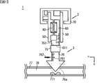
- the fluid control device 1 is, for example, a device that controls the flow rate of a fluid such as water or oil or a fluid such as powder.
- the fluid control device 1 has an actuator 2 and a valve device 3.
- the actuator 2 is, for example, an electric actuator.
- the actuator 2 has a case 70, an elastic portion 40, a drive portion 50, and a moving portion (drive shaft) 60.
- the valve device 3 has a connecting portion 75 connected to the actuator 2, a valve body 76 connected to the connecting portion 75, a scale 761, a mark 762, and a pipe portion 77 through which the fluid 78 flows.
- a contact portion 771 is provided on the + X direction side of the pipe portion 77.
- the end portion 611 of the actuator 2 moves in the + X direction or the ⁇ X direction by driving the actuator 2.
- the connection portion 75 and the valve body 76 of the valve device 3 also move in the + X direction or the ⁇ X direction.
- the scale 761 is provided on the side surface of the valve body 76 along the X direction.
- the mark 762 is provided so as to face the scale 761 so that the relative position with respect to the pipe portion 77 does not change. Therefore, the user can know the position of the valve body 76 in the X direction by reading the scale 761 corresponding to the mark 762.
- the actuator 2 moves the end portion 611 in the ⁇ X direction, and the valve body 76 moves in the ⁇ X direction.
- the flow path of the pipe portion 77 becomes wider, and the flow rate of the fluid 78 flowing through the valve device 3 increases.
- the actuator 2 moves the end portion 611 in the + X direction, and the valve body 76 moves in the + X direction.
- the fluid control device 1 can move the actuator 2 in the + X direction until the valve body 76 moves to the position of 76a and the valve body 76 and the contact portion 771 of the pipe portion 77 come into contact with each other.
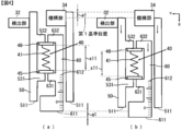
- the actuator 2 includes a case 70, an elastic unit 40, a drive unit 50, a moving unit (drive shaft) 60, an operation unit 31, a detection unit 32, a control unit 33, and a mechanism. It has a part 34 and.
- the case 70 houses a circuit such as a control unit 33, a mechanism unit 34, a part of a drive unit 50, and the like.
- the operation unit 31 is provided outside the case 70, and external control signals are transmitted from a plurality of user-operable operation buttons (not shown) or an external device (not shown). It has an input unit to be supplied.
- the operation unit 31 outputs the operation signal S1 in response to the operation of the operation buttons by the user and the external control signal.
- the detection unit 32 is, for example, a sensor for detecting the operation (drive), stop, etc. of the drive unit 50.
- the detection unit 32 is, for example, a position detection sensor such as a potentiometer or an encoder.
- the detection unit 32 may be a sensor that detects linear movement or a sensor that detects rotation. In this embodiment, the detection unit 32 is a potentiometer that detects linear movement.
- the detection unit 32 is fixed to the case 70, detects the movement of the drive unit 50 by using a brush (not shown) that slides on the drive unit 50, and outputs the detection signal S2.
- the detection signal S2 is stored in the storage unit 35 of the control unit 33.
- the control unit 33 has, for example, a microcomputer (not shown) and a storage unit 35.
- the control unit 33 determines (detects) whether or not the drive unit 50 has stopped based on the detection signal S2.
- the control unit 33 performs an operation using the operation signal S1 output from the operation unit 31, the detection signal S2 output from the detection unit 32, and the information stored in the storage unit 35, and outputs the control signal S3. To do.
- the control unit 33 performs the first control, the second control, and the normal control, which will be described later.
- the mechanism unit 34 has a motor (not shown) and a cam mechanism (not shown).
- the motor may be, for example, a rotating motor or a linearly driven motor.
- a DC motor, an AC motor, a stepping motor, an ultrasonic motor, or the like can be used.
- a stepping motor is used in order to realize high accuracy and high torque.
- the cam mechanism can adopt any configuration.
- the rotary drive and the linear drive may be converted, the rotary drive may be converted to the rotary drive, the linear drive may be converted to the linear drive, or the rotary drive may be rotated.
- it may be converted into a linearly driven one.
- a cam mechanism that converts the rotational drive of the motor into a linear drive (+ X direction or ⁇ X direction) is used.
- the mechanism unit 34 drives the motor based on the control signal S3, and the driving force of the motor is supplied to the cam mechanism.
- the cam mechanism uses the supplied driving force to drive the driving unit 50 with a predetermined driving force.
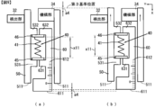
- the drive unit 50 includes a base 51 extending in the X direction, an end portion 511 which is an end of the base 51 on the + X direction side, and a first protrusion extending in the ⁇ Y direction from a portion of the base 51 on the + X direction side. It has 531 and a second protrusion 532 extending in the ⁇ Y direction from the portion of the substrate 51 on the ⁇ X direction side.
- the moving portion 60 includes a base 61 extending in the X direction, an end portion 611 which is an end of the base 61 on the + X direction side, a scale 612 provided on a surface facing the drive unit 50, and a ⁇ X direction side of the base 61. It has a second protrusion 632 extending in the Y direction from the portion 632 and a first protrusion 631 extending in the Y direction from a portion of the substrate 61 on the + X direction side of the second protrusion 632.
- the elastic portion 40 has an elastic body 41, a support member 45 provided on one end side of the elastic body 41, and a support member 46 provided on the other end side of the elastic body 41.
- the elastic body 41 is, for example, an elastic member such as a metal spring or rubber.
- the support member 45 is provided on the ⁇ X direction side of the first protrusion 531 and the first protrusion 631 so as to be in contact with at least one of the first protrusion 531 and the first protrusion 631.
- the support member 46 is provided on the + X direction side of the second protrusion 532 and the second protrusion 632 so as to be in contact with at least one of the second protrusion 532 and the second protrusion 632.
- the natural length x10 [mm] (not shown) of the elastic body 41 is the distance between the first protrusion 531 and the second protrusion 532, or the distance between the first protrusion 631 and the second protrusion 632. Longer than the interval with. Therefore, the elastic body 41 pressurizes the support member 45 and the support member 46 with an elastic force in a direction in which the distance between the support member 45 and the support member 46 increases.
- 4 to 6 are diagrams for explaining the operation of the actuator of the first embodiment.
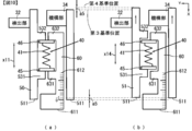
- FIG. 4A is a diagram showing an initial state.
- the first protrusion 531 and the first protrusion 631 are at positions facing each other, and the second protrusion 532 and the second protrusion 632 are at positions facing each other.
- the support member 45 is supported by the first protrusion 531 and the first protrusion 631, and the support member 46 is supported by the second protrusion 532 and the second protrusion 632.
- the control unit 33 does not output the control signal S3 for driving the drive unit 50, and the drive unit 50 is stopped.
- the detection unit 32 outputs the detection signal S2 to the control unit 33, and the control unit 33 stores the position information of the drive unit 50 in the storage unit 35 based on the detection signal S2.
- the elastic body 41 is pressurized and compressed by the first protrusion 531 and the first protrusion 631 and the second protrusion 532 and the second protrusion 632, and has a length of x11 [mm]. In the state of FIG. 4A, the elastic body 41 is shrunk by (x10-x11) [mm] from the natural length x10 [mm].
- the end portion 511 of the drive unit 50 is at the 0 (zero) position of the scale 612 of the moving unit 60. This position is referred to as the first position.
- FIG. 4B shows a state in which the driving unit 50 is driven in the + X direction by the first driving force from the state shown in FIG. 4A.
- the control unit 33 outputs a control signal S3 for driving the drive unit 50 in the + X direction with the first driving force, and the drive unit 50 drives the drive unit 50 in the + X direction with the first driving force.
- the detection unit 32 outputs the detection signal S2 to the control unit 33, and the control unit 33 stores the position information of the drive unit 50 in the storage unit 35 based on the detection signal S2.
- the first driving force is, for example, a force smaller than the force F0 (the force by which the first protrusion 531 and the second protrusion 532 compress the elastic body 41).
- the first driving force is preferably, for example, a value of a force F0 or less and 1/20 or more of the force F0. More preferably, the first driving force is, for example, a value of a force F0 or less and 1/10 or more of the force F0.
- the first driving force of the driving portion 50 is transmitted to the moving portion 60 via the elastic portion 40. Then, the drive unit 50 and the moving unit 60 move in the + X direction, and the valve body 76 moves in the + X direction.
- the moving portion 60 receives a drag force from the contact portion 771 and cannot move. Since the first driving force is equal to or less than the force F0 and the elastic portion 40 does not contract, the driving portion 50 cannot move either.
- the detection unit 32 outputs the detection signal S2 to the control unit 33, and the control unit 33 stores the position information of the drive unit 50 as the first reference position in the storage unit 35 based on the detection signal S2.
- FIG. 5 (a) is in the same state as FIG. 4 (b).
- FIG. 5B shows a state in which the driving unit 50 is driven in the + X direction by the second driving force from the state shown in FIG. 5A.
- the control unit 33 outputs a control signal S3 for driving the drive unit 50 in the + X direction with the second driving force, and drives the drive unit 50 in the + X direction with the second driving force.
- the second driving force is, for example, a force larger than the force F0 (the force by which the first protrusion 531 and the second protrusion 532 compress the elastic body 41).
- the detection unit 32 outputs the detection signal S2 to the control unit 33, and the control unit 33 stores the position information of the drive unit 50 in the storage unit 35 based on the detection signal S2.
- the moving portion 60 cannot move (almost) in the + X direction. Therefore, when the driving unit 50 is driven in the + X direction by the second driving force, the elastic body 41 is compressed. The second driving force is transmitted to the moving portion 60 via the elastic portion 40, and the valve body 76 and the contact portion 771 are pressed more strongly (retightening).
- the control unit 33 sets the second control end condition described later (the distance for moving the drive unit 50 by the second control is a2 [ mm]) is determined to be satisfied, and the drive unit 50 is stopped. At this time, the control unit 33 stores the position information of the drive unit 50 as the second reference position in the storage unit 35 based on the detection signal S2.
- the driving unit 50 moves a2 [mm] by the second driving force, and the length of the elastic body 41 is x12 [mm], which is shorter than x11 [mm].
- x11 [mm] x12 + a2 [mm]
- an elastic force F1 k1 ⁇ (x10-x12) [N] is generated in the elastic body 41.
- the second driving force is, for example, equal to or less than the rated driving force during normal control of the motor of the mechanical unit 34 and equal to or greater than the force F0 (the force with which the first protrusion 531 and the second protrusion 532 compress the elastic body 41). It is preferably the value of. More preferably, the second driving force is, for example, a value equal to or less than the rated driving force at the time of normal control of the motor and at least twice the force F0.
- FIG. 6A is a diagram for explaining a state similar to that of FIG. 4B.
- the position of the moving portion 60 is fixed by using an external member (not shown) in the state of FIG. 4A.
- the control unit 33 performs the first control of driving the drive unit 50 in the ⁇ X direction with the third driving force.
- the third driving force is, for example, a force opposite to the first driving force and equal to the first driving force. Since the third driving force is smaller than, for example, the force F0 (the force by which the first protrusion 531 and the second protrusion 532 compress the elastic body 41), the driving unit 50 cannot move.
- the control unit 33 Based on the detection signal S2, the control unit 33 stores the position information of the drive unit 50 in the storage unit 35 as a third reference position.
- the end portion 511 of the drive unit 50 is at the 0 (zero) position (first position) of the scale 612 of the moving unit 60.
- the control unit 33 outputs a control signal S3 for driving the drive unit 50 in the ⁇ X direction with the fourth driving force, and the drive unit 50 drives the drive unit 50 in the ⁇ X direction with the fourth driving force.
- the second control is performed.
- the fourth driving force is, for example, a force having the same magnitude as the second driving force and in the opposite direction.
- the control unit 33 sets the second control end condition (the distance for moving the drive unit 50 by the second control is ⁇ a3 [. mm]) is determined to be satisfied, and the drive unit 50 is stopped. At this time, the control unit 33 stores the position information of the drive unit 50 as the fourth reference position in the storage unit 35 based on the detection signal S2.
- the length of the elastic body 41 is x13 [mm], which is shorter than x11 [mm].
- x11 [mm] x13 + a3 [mm]
- an elastic force F2 k1 ⁇ (x10-x13) [N] is generated in the elastic body 41.
- the end portion 511 of the drive unit 50 is 2 (2 scales) in the ⁇ X direction from the 0 (zero) position of the scale 612. Is just moving. This position is referred to as the third position.
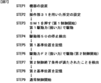
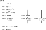
- FIG. 7 is a diagram for explaining the operation of the fluid control device of the first embodiment.
- step 1 the device is installed.
- the moving portion 60 of the actuator 2 see FIG. 1
- the connecting portion 75 of the valve device 3 see FIG. 1
- the necessary power supply is supplied to the fluid control device 1.
- step 2 the user makes a predetermined setting using the operation unit 31.
- the operation unit 31 outputs information regarding a predetermined setting to the control unit 33 as an operation signal S1.
- the control unit 33 stores information (operation signal S1) related to a predetermined setting in the storage unit 35.
- the predetermined settings are, for example, the setting of the magnitude of the first driving force, the setting of the magnitude of the second driving force, the setting of the magnitude of the third driving force, the setting of the magnitude of the fourth driving force, and the second.
- Examples include setting control end conditions and setting driving force during normal control.
- Examples of the driving force during normal control include a rated driving force during normal control, a maximum driving force during normal control, and a minimum driving force during normal control.
- the magnitude of the first to fourth driving forces may be set by a value corresponding to the force [N], may be set by a value corresponding to the pressure [Pa], or may be set by a value corresponding to the first to fourth driving forces.
- the length [mm] of the elastic body 41 contracted by applying the driving force to the elastic body 41 may be set, or it may be set by the rotation speed of the motor of the mechanism unit 34, the current supplied to the motor, or the like. You may.
- the elastic body 41 has a natural length x10, a length x11 (see FIG. 4A), and a force F0 (a force by which the first protrusion 531 and the second protrusion 532 compress the elastic body 41). ) Is informed to the user in advance. Therefore, the user sets, for example, a force F0 ⁇ (1/10) as the first driving force.
- the rated driving force during normal control is set as the second driving force.
- an integral multiple of the force F0 may be set as the second driving force.
- the second control end condition is an arbitrary condition for terminating the second control.
- the second control end condition is an arbitrary condition for terminating the second control. For example, in the present embodiment shown in FIG. 5, "distance a2 [mm] for moving the drive unit 50 by the second control" is set as the second control end condition.
- Whether or not the drive unit 50 has moved a distance a2 [mm] may be determined by, for example, the control unit 33 detecting the rotation speed of the motor of the mechanism unit 34, or the control unit 33 may determine whether or not the drive unit 50 has moved. The determination may be made by monitoring the detection signal S2 of 32, or may be determined by another method.
- the rotation speed of the motor and the moving distance of the drive unit 50 have a one-to-one correspondence. Further, when the drive unit 50 moves by a distance a2 [mm] during the second control, the elastic body 41 contracts by a2 [mm].
- x11 [mm] x12 + a2 [mm]
- the length of the elastic body 41 changes from x11 [mm] to x12 [mm].
- an elastic force F1 k1 ⁇ (x10-x12) [N] is generated in the elastic body 41.
- the elastic force F1 corresponds to the force with which the valve body 76 pressurizes the contact portion 771 when the second control is completed.
- the operation unit 31 outputs the elastic force F1 to the control unit 33 as the operation signal S1.
- the control unit 33 calculates the movement distance a2 [mm] of the drive unit 50 from the elastic force F1, calculates the rotation speed A [rotation] of the stepping motor for moving the drive unit 50 by the movement distance a2 [mm], and calculates the rotation speed A [rotation].
- the rotation speed A [rotation] is output to the mechanism unit 34 as the control signal S3.
- the setting of the second control end condition is not limited to the above example.
- the operation unit 31 when the user knows the spring multiplier k1 [N / mm] of the elastic body 41, the user may input the moving distance a2 [mm] of the drive unit 50 by using the operation unit 31.
- the operation unit 31 generates the moving distance a2 [mm] as the operation signal S1
- the control unit 33 generates the rotation speed A [rotation] as the control signal S3, so that the stepping motor of the mechanism unit 34 is A [. Rotate].
- the second control end condition is not limited to the moving distance of the drive unit 50.
- the end condition may be that a predetermined time has elapsed since the start of the second control, the end condition may be that the motor of the mechanism unit 34 has stopped, or the valve body 76 or the contact unit 771 may have an end condition.
- the termination condition may be that it is detected that the pressing force between the valve body 76 and the contact portion 771 exceeds a predetermined value by using the installed sensor.
- step 3 the first control is started when the user presses the start button SW1 of the operation unit 31.
- the first control is, for example, a control for driving the driving unit 50 with the first driving force.
- the operation unit 31 outputs an operation signal S1 to the effect that the start button SW1 (not shown) is pressed to the control unit 33.
- the detection unit 32 outputs the detection signal S2 to the control unit 33.
- the control unit 33 generates a control signal S3 to drive the drive unit 50 in the + X direction with the first driving force based on the information stored in the storage unit 35, and outputs the control signal S3 to the mechanism unit 34.
- the mechanism unit 34 drives the motor based on the control signal S3, and drives the drive unit 50 in the + X direction with the first driving force.
- the moving unit 60 moves in the + X direction, and the valve body 76 (see FIG. 1) approaches the contact unit 771 (see FIG. 1).
- the valve body 76 comes into contact with the contact portion 771.
- the moving portion 60 cannot move. Since the first driving force is smaller than the force F0, the driving unit 50 cannot compress the elastic body 41, and the movement of the driving unit 50 also stops.
- control unit 33 detects (determines) the stop of the drive unit 50 based on the detection signal S2 of the detection unit 32 (step 4).
- step 5 the control unit 33 stores the position information of the drive unit 50 in the storage unit 35 as the first reference position.
- the detection signal S2 of the detection unit 32 when the drive unit 50 is stopped becomes the first reference position.
- the end portion 511 of the drive unit 50 is located at the 0 (zero) position (first position) of the scale 612 of the moving unit 60 (see FIG. 4B).
- the second control is, for example, a control for driving the driving unit 50 with a second driving force.
- control unit 33 In the second control, the control unit 33 generates a control signal S3 to drive the drive unit 50 in the + X direction with the second driving force based on the information stored in the storage unit 35, and outputs the control signal S3 to the mechanism unit 34. ..
- the mechanism unit 34 drives the motor based on the control signal S3, and drives the drive unit 50 in the + X direction with the second driving force.
- valve body 76 and the moving portion 60 cannot move (almost) in the + X direction, the elastic body 41 contracts according to the movement of the driving portion 50.
- the valve body 76 is in pressure contact with the contact portion 771.
- the control unit 33 repeatedly determines whether or not the second control end condition set in step 2 is satisfied.
- “distance a2 [mm] for moving the drive unit 50 by the second control is set as the second control end condition, so that the control unit 33 Determines whether or not the second control end condition is satisfied by repeatedly detecting the rotation speed of the motor of the mechanism unit 34.
- the control unit 33 detects the detection signal S2 of the detection unit 32.
- control unit 33 stores the position information of the drive unit 50 (detection signal S2 of the detection unit 32) when it is determined that the second control end condition is satisfied in the storage unit 35 as the second reference position.
- the control unit 33 stops driving the drive unit 50 and ends the second control.
- the end portion 511 of the drive unit 50 is located at the +2 position (second position) of the scale 612 of the moving unit 60 (see FIG. 5B).
- step 9 the control unit 33 starts normal control because the second control is completed.
- the normal control is, for example, a control for moving the drive unit 50, the moving unit 60, the valve body 76, and the like by using at least one of the first to fourth reference positions.
- the operation unit 31 outputs the operation signal S1 based on the external control signal supplied to the input unit of the operation unit 31 or the operation of the operation unit 31 by the user.
- the control unit 33 generates a control signal S3 to drive the drive unit 50 based on the information stored in the operation signal S1, the detection signal S2, and the storage unit 35, and outputs the control signal S3 to the mechanism unit 34.
- the valve body 76 can be freely controlled.
- control unit 33 normally controls the second reference position as the closed position of the valve device 3 (a state in which the valve device 3 is closed and a state in which the fluid 78 does not flow).
- first reference position For normal control, only one of the first reference position, the second reference position, the third reference position and the fourth reference position may be used, or the first reference position, the second reference position, the third reference position and the third reference position may be used. 4 Two or more reference positions may be used.
- the first reference position is a state in which the fluid 78 hardly flows
- the second reference position is a state in which the fluid 78 does not flow at all. It may be. Since the fluid control device 1 is provided with a scale 761 and a mark 762, in normal control, the user visually recognizes the scale 761 and the mark 762 to open / close the valve device 3 and operate the valve body 76. Can be easily confirmed
- the position of the mark 762 with respect to the scale 761 can be detected by using a position detection sensor (referred to as a second position detection sensor) such as a potentiometer or an encoder.
- a position detection sensor referred to as a second position detection sensor
- the output signal of the second position detection sensor is preferably supplied to the control unit 33. This is because more advanced control can be realized by using the detection signal S2 (see FIG. 3) output from the detection unit 32 (see FIG. 3) described above and the output signal of the second position detection sensor. ..
- the fluid control device 1 can move the valve body 76 to a desired position by controlling the actuator 2.
- the actuator 2 of the present embodiment includes a driving unit 50 that can drive at least one of the first driving force and the second driving force, a moving unit 60 that can move in a predetermined direction, and a first driving force and a second driving force from the driving unit 50. It has an elastic portion 40 to which at least one of the driving forces is supplied and a force for the moving portion 60 to move is supplied to the moving portion 60.
- the driving force of the driving unit 50 is supplied to the moving unit 60 via the elastic unit 40, and the elastic unit 40 is compressed by driving the driving unit 50 when the moving unit 60 is stopped. can do.
- the actuator 2 of the present embodiment has a detection unit 32 that supplies a detection signal for detecting the stop of the drive unit 50 to the control unit 33, the control unit 33 performs the first control and then detects the detection unit 32.
- the first control can be ended and the second control can be started by detecting the stop of the drive unit 50 based on the detection signal of.
- control unit 33 of the actuator 2 has a first control capable of driving the drive unit 50 with a first driving force and a second control capable of driving the drive unit 50 with a second driving force stronger than the first driving force. And are possible.
- control unit 33 can bring the valve body 76 and the contact unit 771 into contact with each other with a weak force by the first control. Further, by the second control, the valve body 76 and the contact portion 771 can be brought into pressure contact with each other with a strong force.
- the first driving force is set to a value smaller than the force F0 (the force with which the first protrusion 531 and the second protrusion 532 compress the elastic body 41), so that the first control is applied.
- the amount of shrinkage of the elastic body 41 is zero or a very small value. Since the second driving force is set to a value larger than the force F0, the amount of contraction of the elastic body 41 by the second control is a relatively large value.
- the second control is started from the state where the valve body 76 and the contact portion 771 are brought into contact with each other by the first control, and the "movement amount of the drive unit 50 in the X direction by the second control" is "first. It can be regarded as equal to "the amount of contraction of the elastic body 41 from the start of the control to the completion of the second control".
- the control unit 33 corresponds to the "movement amount of the drive unit 50 by the second control in the X direction" at the time of the second control, and the control signal S3 Is supplied to the mechanism unit 34, "a force (tightening amount) by which the valve body 76 pressurizes the contact portion 771 when the second control is completed" can be realized.
- the force (tightening amount) for the valve body 76 to pressurize the contact portion 771 can be easily set by using the operation unit 31, so that suitable flow rate control of the fluid 78 can be realized. ..
- the suitable tightening amount the force with which the valve body 76 pressurizes the contact portion 771 fluctuates depending on the temperature and composition of the fluid 78, the aged deterioration of the valve body 76 and the contact portion 771, etc.
- the operation unit 31 Can be used to preferably change the retightening amount.
- FIG. 8 is a diagram for explaining the fluid control device of the second embodiment
- FIG. 9 is a diagram for explaining the operation of the actuator of the second embodiment
- FIG. 10 is a diagram for explaining the operation of the actuator of the second embodiment. Another figure for. In the following description, the same reference numerals will be given to the same configurations as those shown in FIGS. 1 to 7, and duplicate description will be omitted.
- the fluid control device 1' has an actuator 2 and a valve device 3'.
- the valve device 3' is replaced with the connection portion 75, the valve body 76, the scale 761, the mark 762, the fluid 78, the pipe portion 77 and the contact portion 771, and the connection portion 75a, the valve body 76c, 76e, the scale 761a, 761b, and the mark. It has 762a, 762b, fluids 78a, 78b, pipe portions 77a, 77b, and contact portions 771a, 771b.
- the connecting portion 75a is connected to the valve bodies 76c and 76e.
- the valve body 76c is provided on the + X direction side of the connecting portion 75a, and the valve body 76e is provided on the ⁇ X direction side of the connecting portion 75a.
- the scales 761a and 761b are provided on the valve bodies 76c and 76e.
- the marks 762a and 762b are provided so as to face the scales 761a and 761b.
- the contact portions 771a and 771b are provided in the pipe portions 77a and 77b.
- valve body 76c comes into contact with the contact unit 771a and the flow of the fluid 78a is restricted.
- the valve body 76e comes into contact with the contact unit 771b and the flow of the fluid 78b is restricted.
- valve body 76c Since the operation of the valve body 76c, the scale 761a, the mark 762a, the fluid 78a, the pipe portion 77a, and the contact portion 771a is the same as the operation of the fluid control device 1 of the first embodiment described above, the valve body 76e, the scale 761b, The operation of the mark 762b, the fluid 78b, the pipe portion 77b, and the contact portion 771b will be mainly described.
- FIG. 9A is a diagram showing an initial state.
- the control unit 33 does not output the control signal S3 for driving the drive unit 50, and the drive unit 50 is stopped.
- the end portion 511 of the drive unit 50 is at the 0 (zero) position (first position) of the scale 612 of the moving unit 60.
- the elastic body 41 has a length of x11 [mm]. Assuming that the spring multiplier of the elastic body 41 is k1, in the state of FIG. 4A, the elastic body 41 is subjected to the force F0 (the force by which the first protrusion 531 and the second protrusion 532 compress the elastic body 41). It is compressed.
- FIG. 9B shows a state in which the driving unit 50 is driven in the ⁇ X direction by a third driving force from the state shown in FIG. 9A.
- the third driving force is, for example, a force opposite to the first driving force and equal to the first driving force.
- the control unit 33 outputs a control signal S3 for driving the drive unit 50 in the ⁇ X direction with the third driving force, and starts the first control in which the drive unit 50 drives the drive unit 50 in the ⁇ X direction with the third driving force.
- the control unit 33 stores the position information of the drive unit 50 as the third reference position in the storage unit 35 based on the detection signal S2 of the detection unit 32.
- FIG. 10 (a) is the same state as in FIG. 9 (b).
- FIG. 10B shows a state in which the driving unit 50 is driven in the ⁇ X direction by the fourth driving force from the state shown in FIG. 10A.
- the control unit 33 outputs a control signal S3 for driving the drive unit 50 in the ⁇ X direction with the fourth driving force, and drives the drive unit 50 in the ⁇ X direction with the fourth driving force.
- the second control is performed.
- the fourth driving force is, for example, a force opposite to the second driving force and equal to the second driving force.
- the fourth driving force is, for example, a force larger than the force F0 (the force by which the first protrusion 531 and the second protrusion 532 compress the elastic body 41).
- the moving portion 60 cannot move (almost) in the ⁇ X direction. Therefore, when the driving unit 50 is driven in the ⁇ X direction by the fourth driving force, the elastic body 41 is compressed. The fourth driving force is transmitted to the moving portion 60 via the elastic portion 40, and the valve body 76e and the contact portion 771b are pressed more strongly (retightening).
- the control unit 33 sets the second control end condition (for example, the distance for moving the drive unit 50 by the second control is ⁇ ). It is determined that a5 [mm]) is satisfied, and the drive unit 50 is stopped. At this time, the control unit 33 stores the position information of the drive unit 50 as the fourth reference position in the storage unit 35 based on the detection signal S2.
- the end portion 511 of the drive unit 50 is a5 (1 scale) in the ⁇ X direction from the 0 (zero) position of the scale 612. Is just moving. This position is referred to as the third position.
- the actuator 2 of the present embodiment described above has the same configuration as the actuator 2 of the first embodiment, it is possible to obtain the same excellent action and effect.
- the fluid control device 1'of the present embodiment described above has an actuator 2 and a valve device 3'.
- the valve device 3' has a connecting portion 75a, a valve body 76c, 76e, a scale 761a, 761b, a mark 762a, 762b, a fluid 78a, 78b, a pipe portion 77a, 77b, and a contact portion 771a, 771b.
- control unit 33 can realize suitable control by using at least one of the first reference position, the second reference position, the third reference position, and the fourth reference position.
- the fluid control device 1' can move the valve body 76c and the valve body 76e to desired positions under the control of the actuator 2.
- the fluid control device 1'of the present embodiment drives the drive unit 50 in the + X direction by the first driving force or the second driving force in the same manner as the operations shown in FIGS. 4 and 5 of the first embodiment.
- the valve body 76c and the contact portion 771a are brought into contact with each other or pressurized at a predetermined pressure, and as shown in FIGS. 9 and 10 of the second embodiment, the drive portion 50 is subjected to a third driving force or a fourth driving force.
- By driving in the ⁇ X direction with a driving force it is possible to realize control in which the valve body 76e and the contact portion 771b are brought into contact with each other or pressurized at a predetermined pressure.
- FIG. 11 is a diagram for explaining the fluid control device of the third embodiment
- FIG. 12 is a diagram for explaining the switch of the actuator of the third embodiment.
- the same reference numerals will be given to the same configurations as those shown in FIGS. 1 to 10, and duplicate description will be omitted.
- the fluid control device 1A has an actuator 2A and a valve device 3 (see FIG. 1).
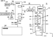
- the actuator 2A has a control unit 33A in place of the control unit 33 shown in FIG. 3 and an operation unit 310 in place of the operation unit 31 shown in FIG.
- the control unit 33A includes a microcomputer (not shown), a storage unit 35, a battery 36, a switch 37, a first terminal 381, a second terminal 382, and a third terminal 383.
- the signal processing device 391 is an external device of the fluid control device 1A.
- the signal processing device 391 is, for example, a personal computer (PC).
- the signal processing device 391 is electrically connected to the first terminal 381 via a predetermined communication network.
- the signal processing device 391 outputs the first operation signal S11, which is a signal of the first communication protocol, to the first terminal 381, and the monitor signal S5, which is the monitor signal of the first communication protocol, is the first terminal 381. Supplied from.
- the first communication protocol is, for example, Modbus communication, but is not limited thereto.
- the control device 392 is an external device of the fluid control device 1A.
- the control device 392 includes, for example, industrial instruments such as various sensors and control devices provided in factories, power plants, and the like.
- the control device 392 for example, the control device performs a predetermined calculation according to signals output from various sensors such as a sensor for detecting the level of liquid and a temperature sensor, and the second communication protocol is different from the first communication protocol.
- the second operation signal S12 is output from the control device to the second terminal 382.
- the second communication protocol is, for example, communication defined by an analog current signal of 4 mA to 20 mA standardized in an industrial instrument, but is not limited thereto.
- the operation unit 310 is provided outside the case 70 (see FIG. 2), for example.
- the operation unit 310 has a plurality of operation buttons (not shown) that can be operated by the user, and an electric circuit (not shown) for generating a signal.
- the operation unit 310 outputs a third operation signal S13 which is electrically connected to the third terminal 383 and is a signal of a third communication protocol different from the first communication protocol and the second communication protocol.
- the third terminal 383 is a connector for a LAN cable, a USB cable, or the like, and the operation unit 310 is electrically connected to the third terminal 383 by a LAN cable, a USB cable, or the like.
- the storage unit 35 of the control unit 33A controls the first operation signal S11 supplied from the signal processing device 391, the second operation signal S12 supplied from the control device 392, and the third operation signal S13 supplied from the operation unit 310. Information such as the calculation result of unit 33A is stored.
- the battery 36 supplies electric power to the control unit 33A and the like when the power of the fluid control device 1A is turned off or when a power failure occurs.
- the switch 37 of the control unit 33A is provided, for example, in a predetermined area on the outer wall of the case 70 (see FIG. 2).
- the switch 37 is connected to the microcomputer of the control unit 33A by using electrical wiring (not shown).
- the switch 37 can select any switch such as a tact switch, a DIP switch, a volume switch, and various buttons.
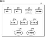
- FIG. 12 is a diagram for explaining the switch 37.
- the switch 37 has a plurality of operation buttons 371 to 378b that can be operated by the user.
- the power button 371 is a power button for the fluid control device 1A.
- the stop button 372 is a button for urgently stopping the fluid control device 1A.
- the auto setup button 375 is a button for starting the above-mentioned first control and second control.
- the control operation in which the second control is performed after the first control is performed is referred to as an auto setup.
- the first control and the second control are automatically executed only by the user pressing the auto setup button 375.
- the settings of the first control and the second control are preferably stored in the storage unit 35 in advance at the time of shipment from the factory.
- the manual operation button 376 is a button for determining whether or not to perform manual operation. For example, when the manual operation button 376 is turned on, the manual operation mode is set, and when the manual operation button 376 is turned off, the non-manual operation mode is set.
- Buttons 377a to 377c are other buttons.
- the other buttons are buttons that allow arbitrary operations such as inputting numbers and characters, selecting YES and NO, and selecting one of a plurality of items.
- the upper drive button 378a is a button for driving the drive unit 50 to the upper position (-X direction side), and the lower drive button 378b drives the drive unit 50 to the lower side (+ X direction side) position. It is a button to do.
- FIG. 13 is a diagram for explaining the operation of the fluid control device of the third embodiment
- FIG. 14 is another diagram for explaining the operation of the fluid control device of the third embodiment
- FIG. 15 is a diagram of the third embodiment.
- FIG. 16 is still another figure for explaining the operation of the fluid control device of the third embodiment.
- the same reference numerals will be given to the same configurations as those shown in FIGS. 1 to 12, and duplicate description will be omitted.
- the fluid control device of the present embodiment can be switched between the manual mode and the non-manual mode.
- the manual mode is a mode in which various controls can be performed by using the switch 37 and the operation unit 310.
- the manual operation button 376 shown in FIG. 12 is turned on, the manual mode is set, and when the manual operation button 376 is turned off, the non-manual mode is set.
- the auto setup button 375 or the operation unit 310 is used to instruct the start of the auto setup, the operation unit 310 is used to set the position of the drive unit 50 during the auto setup operation, or the upper side.
- the drive button 378a, the lower drive button 378b, and the operation unit 310 can be used to execute the axial operation of the drive unit 50 during normal control.
- the first communication (Modbus communication) mode when the first communication (Modbus communication) mode is set, if the detailed setting of the first communication is set to "monitor using the first communication", the user signals from the first terminal 381.
- the state of the actuator 2A can be confirmed by using the monitor signal S5 supplied to the processing device 391.
- the first communication (Modbus communication) mode When the first communication (Modbus communication) mode is set, if the detailed setting of the first communication is set to "perform axis operation using the first communication", the first communication is used during normal control. It is possible to control (axis operation) to drive the drive unit 50.
- the first communication mode When the first communication mode is set, if the detailed setting of the first communication is set to "set using the first communication", the first communication (signal processing device 391) is used for auto. It is possible to instruct the start of setup and set the position of the drive unit 50 during the auto setup operation.
- the second communication current signal of 4 mA to 20 mA
- the detailed setting of the first communication is set to "monitor using the first communication”
- the second communication is performed during normal control.
- the drive unit 50 can be axially operated using the above, and the user can confirm the state of the actuator 2A by using the monitor signal S5 supplied from the first terminal 381 to the signal processing device 391.
- the second communication mode When the second communication mode is set, if the detailed setting of the first communication is set to "Set using the first communication", the first communication is used to instruct the start of auto setup. Alternatively, the position of the drive unit 50 and the like can be set.
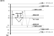
- the user turns on the power button 371 of the switch 37 in step 11.
- the valve body 76 is stopped at the start position of 8 mm.
- the scale on the vertical axis of FIG. 16 is the reading value of the scale 761 shown in FIG. 1 (the value of the scale 761 corresponding to the position of the mark 762).
- the position of the valve body 76 is set as the start position (8 mm), but the position of the drive unit 50, the position of the moving unit 60, and the like may be set (specified) as the start position.
- the upper maximum position is provided at a position 2 mm above the start position 8 mm, and the upper hard limit is provided at a position 0 mm above the upper maximum position.
- the upper maximum position is the uppermost position that can be driven by electrical control, and the upper hard limit is the uppermost position that can be driven mechanically.
- a lower maximum position is provided at a position 18 mm below the starting position 8 mm
- a lower hard limit is provided at a position 20 mm below the lower maximum position.
- the lower maximum position is the lowest position that can be driven by electrical control
- the lower hard limit is the lowest position that can be driven mechanically.
- the positions of the valve body 76 are set to the upper maximum position, the upper hard limit, the lower maximum position, and the lower hard limit, but the position of the drive unit 50, the position of the moving unit 60, and the like are set to the upper side. It may be set (specified) as the maximum position, the upper hard limit, the lower maximum position, and the lower hard limit.
- the seat surface position is, for example, a position when the driving of the driving unit 50 is stopped when the driving unit 50 is driven by the first control (first driving force).
- the seating surface position is, for example, the position of the drive unit 50 when the drive unit 50 is stopped when the drive unit 50 is driven by the first control, or the valve body when the drive unit 50 is driven by the first control. It may be a position where the 76 stops, or a position when the valve body 76 and the contact portion 771 (see FIG. 1) come into contact with each other when the drive unit 50 is driven by the first control.
- the seat surface position (15 mm) is the position of the valve body 76 when the drive of the drive unit 50 is stopped when the drive unit 50 is driven by the first control.
- the position of the valve body 76 is set as the seat surface position, but the position of the drive unit 50, the position of the moving unit 60, and the like may be set (specified) as the seat surface position.
- the lower stop position is, for example, a position where the valve device is in a closed state (a state in which the valve device 3 is closed. A state in which the fluid 78 does not flow) or a second control (second driving force) drives the drive unit 50. This is the position when the drive unit 50 stops at the time of the operation.
- the lower stop position may be, for example, the position of the drive unit 50 when the drive unit 50 is stopped when the drive unit 50 is driven by the second control (second driving force), or the position of the drive unit 50 when the drive unit 50 is stopped. It may be the position when the valve body 76 stops when the driving unit 50 is driven by the second driving force), or the position determined by the magnitude of the second driving force and the elastic force of the elastic body 41.
- the lower stop position (15.1 mm) is the valve body when the drive unit 50 stops when the drive unit 50 is driven by the second control (second driving force). It is the position of 76.
- the lower stop position is 15.1 mm, but the lower stop position is a value substantially equal to the seat surface position (15 mm) such as 15.01 mm and 15.001 mm. There may be.
- the position of the valve body 76 is set as the lower stop position, but the position of the drive unit 50, the position of the moving unit 60, and the like may be set (specified) as the lower stop position.
- the amount of displacement between the seat surface position and the lower stop position is such that the seat surface position and the lower stop position are defined by the position of the valve body 76. It is a value obtained by adding the amount of contraction of the elastic body 41 to the amount of displacement between the seat surface position and the lower stop position in the specified case.
- the amount of contraction of the elastic body 41 can be read on the scale 612 (see FIG. 11).
- step 12 the control unit 33A determines whether or not the manual operation mode is set. If the manual operation mode is set, the process proceeds to step 14b or step 15c, and if the manual operation mode is not determined (non-manual operation is determined), the process proceeds to step 13.
- step 13 the user makes detailed settings for the first communication. Specifically, one of "monitoring using the first communication”, “axis operation using the first communication”, and “setting using the first communication” is selected.
- control unit 33A determines that "setting using the first communication" is selected by the user, the control unit 33A proceeds to step 14a. If "Set using first communication" is not selected, the process cannot proceed to step 14a. This is to prevent a malfunction that the user does not intend by confirming the user's intention to make the setting using the first communication.
- step 14a the user uses the signal processing device 391 (first communication) to make settings related to the auto setup operation and other settings.
- the pushing amount is set to 1 mm and the stroke is set to 10 mm as the settings related to the auto setup operation.
- the set value is stored in the storage unit 35.
- the pushing amount can be, for example, a length (shrinking amount) that causes the elastic body 41 to contract during the second control. Further, the pushing amount may be, for example, a value corresponding to the difference between the position where the drive unit 50 is stopped by the first control and the position where the drive unit 50 is stopped by the second control. Further, the pushing amount may be a length that causes the elastic body 41 to contract by the second driving force (the force that drives the driving unit 50 during the second control), or the driving unit 50 contracts the elastic body 41 during the second control. It may be an amount to be driven.
- the pushing amount is a value corresponding to the difference between the position of the drive unit 50 when the drive unit 50 is stopped by the first control and the position of the drive unit 50 when the drive unit 50 is stopped by the second control.
- the first driving force (the force that drives the driving unit 50 during the first control) is, for example, a force F0 (the first protruding portion 531 and the second protruding portion 532 shown in FIG. 3 form an elastic body 41.
- a force smaller than the compressing force is set, and the second driving force is set, for example, a force larger than the force F0.
- the control unit 33A since the elastic force and the second driving force of the elastic body 41 are predetermined, when the user inputs the pushing amount (1 mm) by using the first communication, the control unit 33A has the first control unit 33A.
- 2 Drive unit 50 during control Controls the elastic body 41 to contract and drive 1 mm, and the elastic body 41 is pushed (compressed) by about 1 mm.
- the valve body 76 since the elastic body 41 contracts by about 1 mm, the valve body 76 hardly moves (the valve body 76 moves slightly from the seat surface position (15 mm) to the lower stop position (15.1 mm)). ).
- the drive unit 50 controls the elastic body 41 to contract and drive the elastic body 41 by 2 mm at the time of the second control, and the elastic body 41 has a stronger force. It is pushed (compressed) by about 2 mm. Since the elastic body 41 contracts by about 2 mm, the valve body 76 hardly moves (the valve body 76 moves slightly from the seat surface position (15 mm) to the lower stop position (15.2 mm)).
- the pushing amount is set, but the pushing amount is not limited to this.
- a method of setting the magnitude of the second driving force a method of setting the magnitudes of the first driving force and the second driving force, and the like may be adopted. This is because there is a proportional relationship between the magnitude of the second driving force and the pushing amount.
- the stroke is, for example, an upward length starting from the seating surface position (15 mm) shown in FIG.
- the upper stop position is 5 mm, which is a position 10 mm above the seat surface position (15 mm).
- the position of the valve body 76 is set as the upper stop position, but the position of the drive unit 50, the position of the moving unit 60, and the like may be set (specified) as the upper stop position.
- the upper stop position is a position where the valve body 76 is stopped after the first control is completed and before the second control is started.
- the control unit 33A moves the valve body 76 to the seat surface position (15 mm) by the first control (first driving force), and then the valve body 76 with a force opposite to the first driving force. Is moved to the upper stop position (5 mm), and then the second control is started.
- the starting point of the stroke is not limited to the seating surface position, and may be, for example, a lower stop position (15.1 mm), a lower maximum position (18 mm), or the like.
- the upper stop position (5 mm) is set based on the input stroke, but the upper stop position is set by using the signal processing device 391 (first communication), the operation unit 310, and the like. Needless to say, (5 mm) may be directly input.
- the stroke is a value corresponding to the difference between the position where the valve body 76 is stopped by the first control and the position of the valve body 76 when the second control is started (immediately before the second control is started). There may be. Further, the stroke is a value twice the difference between the position where the valve body 76 is stopped by the first control and the position of the valve body 76 when the normal control is started (immediately before the normal control is started). You may.
- step 15a the user instructs the execution of the auto setup using the signal processing device 391 (first communication).
- step 16 the control unit 33A executes the auto setup under the set conditions, and when the auto setup is completed, the normal control can be executed (step 17).
- control unit 33A waits until the operation unit 310 or the switch 37 is operated by the user.
- the process proceeds to step 14b, and the control unit 33A makes settings related to the auto setup operation and other settings based on the operation of the operation unit 310.
- the pushing amount (1 mm) and the stroke (10 mm) are set by using the operation unit 310 and stored in the storage unit 35.
- step 15b when the user instructs the execution of the auto setup using the operation unit 310 (second communication), the control unit 33A executes the auto setup under the set conditions (step 16). If an instruction is given to execute the auto setup using the operation unit 310 before the predetermined setting using the operation unit 310 is made in step 14b, the step 14b may be skipped and the step 15b may be performed. In this case, it is preferable that the predetermined settings are stored in advance in the storage unit 35 at the time of factory shipment of the device.
- step 15c Auto setup is executed (step 16).
- the necessary settings are set by the actuator 2A. It is preferable to store it in the storage unit 35 in advance at the time of shipment from the factory.
- the valve body 76 is stopped at the start position (8 mm) before the auto setup is executed.
- the pushing amount (1 mm) and the stroke (10 mm) are set as the settings related to the auto setup operation.
- the control unit 33A starts the first control and moves the position of the valve body 76 from the start position (8 mm) to the seat surface position (15 mm). If the valve body 76 reaches the lower maximum position (18 mm) without stopping at a position above the lower maximum position, an abnormality is suspected and error processing is performed. Examples of the error processing include processing for stopping the driving of the valve body 76 (driving unit 50), processing for sounding a warning buzzer (not shown), and the like.
- the control unit 33A stores the stop position in the storage unit 35 as the first reference position.
- the stop position is the seat surface position (15 mm).
- control unit 33A controls so that the valve body 76 (drive unit 50) stops at the upper stop position (5 mm). If the valve body 76 (drive unit 50) stops before reaching the upper stop position (5 mm), an abnormality is suspected and error processing is performed.
- the control unit 33A starts the second control after detecting that the valve body 76 has reached the upper stop position (5 mm), and the valve body 76 moves downward. If the valve body 76 (driving unit 50) stops before reaching the seating surface position (15 mm), an abnormality is suspected and error processing is performed. Error processing is also performed when the valve body 76 reaches the lower maximum position (18 mm) without stopping at a position above the lower maximum position.
- the stop position Is stored in the storage unit 35 as the second reference position.
- the stop position is the lower stop position (15.1 mm).
- the control unit 33A drives the valve body 76 toward the completion position, detects that the valve body 76 has reached the completion position, and then puts the normal control into a state in which normal control can be executed.
- the completion position is a position (10 mm) that is moved upward by 1/2 of the stroke (10 mm) from the seat surface position (15 mm).
- the position of the valve body 76 is set as the completion position, but the position of the drive unit 50, the position of the moving unit 60, and the like may be set (specified) as the completion position.
- the normal control described later starts from the completion position (10 mm). It goes without saying that the method of setting the completion position is arbitrary, and for example, the completion position (10 mm) may be directly input using the operation unit 310, the signal processing device 391 (first communication), or the like.
- step 16 auto setup of FIG. 14
- the normal control can be executed (step 17)
- the user operates the manual operation button 376
- the manual operation mode or the non-manual operation mode is executed. Set to.
- step 27 determines that the manual operation mode has not been determined (it has been determined to be non-manual operation). If so, the process proceeds to step 22.
- step 27 the control unit 33A automatically sets the detailed setting of the first communication to "monitor using the first communication".
- step 28 when the user operates the switch 37 or the operation unit 310, the control unit 33A performs a predetermined operation.
- the user drives the drive unit 50 to the upper ( ⁇ X direction side) or lower side (+ X direction side) position by using the upper drive button 378a, the lower drive button 378b, or the operation unit 310.
- Control axis movement
- step 21 When it is determined in step 21 that the non-manual operation is set, the user selects the first communication (Modbus communication) or the second communication (current signal of 4 mA to 20 mA) using the signal processing device 391. To do.
- the control unit 33A proceeds to step 23 when it is determined that the first communication (Modbus communication) is selected, and step 25 when it is determined that the second communication (current signal of 4 mA to 20 mA) is selected. Proceed to.
- step 23 the user makes detailed settings for the first communication. If the detailed setting of the first communication is set to "perform axis operation using the first communication", the process proceeds to step 24 and the detailed setting of the first communication is set to "perform axis operation using the first communication". If it is not set, abnormal processing is performed.
- the abnormality handling is, for example, a control for stopping the drive unit 50.
- the control unit 33A positions the drive unit 50 on the upper side ( ⁇ X direction side) or the lower side (+ X direction side) based on the first operation signal S11 of the first communication (signal processing device 391).
- step 25 of performing normal control (axis operation) for driving the user makes detailed settings for the first communication.
- step 26 the control unit 33A drives the drive unit 50 to a position on the upper side ( ⁇ X direction side) or lower side (+ X direction side) based on the second operation signal S12 of the second communication (control device 392). Perform normal control (axis operation)
- the axis operation can be performed only when "the axis operation is performed using the first communication". It is possible, and in other settings, the axis operation cannot be performed using the first communication.
- monitoring is performed using the first communication and the second communication is performed only when "monitor using the first communication" is set. It is possible to perform the axis operation using the second communication, and it is not possible to perform the axis operation using the second communication in other settings. In this case, even if a control signal is supplied from any of the first communication (signal processing device 391), the switch 37, and the operation unit 310, normal control is not performed, so that a malfunction unintended by the user can be prevented.
- the user when the manual operation mode is determined (not determined to be non-manual operation), the user can perform normal control using the upper drive button 378a or the lower drive button 378b of the switch 37. ..
- the fluid control device does not normally perform control even if a control signal is supplied from either the first communication (signal processing device 391) or the second communication (control device 392), so that a malfunction that the user does not intend may occur. Can be prevented.
- the setting operation by the first communication (auto setup, setting change, etc.) is allowed, and the second communication. Since the operation by manual operation is not allowed, it is possible to prevent a malfunction not intended by the user.
- FIG. 17 is a diagram for explaining information stored in the storage unit of the fluid control device of the fourth embodiment.
- the same reference numerals will be given to the same configurations as those shown in FIGS. 1 to 16, and duplicate description will be omitted.
- the information shown in FIG. 17 is stored in the storage unit 35 (see FIG. 11) of the control unit 33A (see FIG. 11) of the fluid control device.
- FIG. 17 is an example of the information stored in the storage unit 35, and the present invention is not limited to this.
- FIG. 17 the date [year / month / day] and the time [hour / minute / second] are the date and time and time information in which the information is stored. Specifically, FIG. 17 illustrates the information stored at 8:16 on January 14, 2020, 8:16 on January 15, 2020, and 8:17 on January 15, 2020. ing. In the present embodiment, the information is stored at 1-minute intervals, and the illustration of the information from 8:17 on January 14 to 8:15 on January 15 is omitted in FIG.
- the integrated energization time [hour] is the integrated time when the power button 371 is turned on, and the integrated operation time [hour] is the time when at least one of the mechanism unit 34 and the drive unit 50 is driven. Is the sum of.
- the integrated operating distance [m] is the integrated distance traveled by the drive unit 50, the moving unit 60, or the valve body 76.
- the number of times the motor is started [times] is the sum of the number of times the motor or the drive unit 50 of the mechanism unit 34 is started, and the number of times the motor is reversed [times] is the number of times the drive direction of the motor or the drive unit 50 of the mechanism unit 34 is reversed.
- the number of motor retries [times] is an integrated value of the number of times the motor is started after the mechanism unit 34, the drive unit 50, the moving unit 60, or the valve body 76 has stopped abnormally.
- the operation ratio [%] for each minute is the time [seconds] / 60 [seconds] x 100 [%] at which the motor is driven in the last minute.
- the number of over-frequency operations [times] is the total number of times of over-frequency operation.
- Excessive operation is, for example, an operation in which the motor is started and stopped in a short time.
- the operation with a duty of less than 50% is regarded as an excessive frequency operation.
- the ratio [%] of the opening degree less than 25% is the time [hour] / cumulative energization time [hour] ⁇ 100 [%] when the opening degree was less than 25%, and the ratio [%] of the opening degree 25% to 50%.
- the ratio [%] of the opening 50% to 75% is the opening 50%.
- the time [hour] was ⁇ 75% / integrated energization time [hour] ⁇ 100 [%]
- the ratio [%] with an opening degree of 75% or more was the time [hour] / with an opening degree of 75% or more.
- Lock information [0-2] is information related to the locked state of the motor. 0 is stored in the normal state, 1 is stored when the motor is locked so as to drive the drive unit 50 to the upper position (-X direction side), and the drive unit 50 is stored in the lower side. When the motor is locked so as to be driven to the position (+ X direction side), 2 is stored.
- the storage unit 35 is connected to the microcomputer or the like of the control unit 33A, the information shown in FIG. 17 is processed by the microcomputer as needed.
- the microcomputer may further optimize the auto setup control and the normal control by processing the information shown in FIG. 17, and uses the information shown in FIG. 17 to diagnose the failure of the fluid control device 1A. May be good.
- the microcomputer may output the information shown in FIG. 17 from the first terminal 381 to the signal processing device 391, and use the signal processing device 391 to perform a failure diagnosis of the fluid control device 1A.
- the microcomputer of the control unit 33A controls the microcomputer based on the number of times the motor is started [times] and the number of times the motor is reversed [times] (for example, PID control (Proportional Optical Control), PID Control). ) Can be determined and the control parameters can be automatically adjusted. This is because if the control parameters are inappropriate, the number of times the motor is started and the number of times the motor is reversed increases.
- PID control Proportional Optical Control
- PID Control Proportional Optical Control
- control it may be determined whether or not the control is appropriate by associating the information of the date with the information of the number of times the motor is started and the number of times the motor is reversed. This is because if the number of motor starts and the number of motor reversals increase as the date is newer, it can be determined that the abnormality is due to aged deterioration.
- the microcomputer of the control unit 33A may determine whether or not the control of the microcomputer is appropriate based on the ratio [%] of the opening degree, and automatically adjust the control parameters. This is because if the time at which the predetermined opening degree is abnormal is abnormal, the control parameter may be abnormal.
- the microcomputer of the control unit 33A analyzes the number of motor retries, the operation ratio per minute, the number of excessive operations, lock information, etc., and uses a notification means (not shown) such as a display to make an abnormality in the device. May be notified. This is because the operation ratio per minute, the number of excessive operations, the lock information, and the like include information useful for determining an abnormality.
- the microcomputer of the control unit 33A may notify the replacement time of parts of the device by using the integrated energization time, the integrated operation time, and the like. This is because this information includes information useful for determining the replacement time of parts and the like.
Abstract
[Problem] To provide an actuator and a fluid control device with which a suitable control can be achieved. [Solution] An actuator having: a control unit (33) capable of a first control in which a drive unit (50) is able to drive with a first driving force, and a second control in which the drive unit (50) is able to drive with a second driving force that is stronger than the first driving force; a movement unit (60) capable of moving in a prescribed direction; an elastic member (40) to which at least one of the first driving force and the second driving force is supplied from the drive unit (50), and which supplies force for moving the movement unit (60) to the movement unit (60); and a detection unit (32) for supplying a detection signal for detecting stopping of the drive unit (50) to the control unit (33). The control unit (33) carries out the second control when stopping of the drive unit (50) is detected subsequent to carrying out the first control.
Description
本発明は、アクチュエータ、及び、流体制御機器に関する。
The present invention relates to an actuator and a fluid control device.
特許文献1には、スプリング8,8′とワッシャ9,9′によって軸方向に相互移動が可能であるよう釣合位置に支持された弁体3を有するステッピングモータバルブが記載されている。特許文献1には、常時は弁体3がロータ6と共に回転すること、及び、弁体・弁座間摩擦が増大したとき弁体3の回転が停止したままでロータ6が更に回転できることが記載されている。
Patent Document 1 describes a stepping motor valve having a valve body 3 supported at a balanced position so as to be able to move in the axial direction by a spring 8, 8'and a washer 9, 9'. Patent Document 1 describes that the valve body 3 always rotates together with the rotor 6 and that the rotor 6 can further rotate while the rotation of the valve body 3 is stopped when the friction between the valve body and the valve seat increases. ing.
解決しようとする課題は、好適な制御を実現できるアクチュエータ、及び、流体制御機器を提供することである。
The problem to be solved is to provide actuators and fluid control devices that can realize suitable control.
本発明の第1の観点に係るアクチュエータは、駆動部を第1駆動力で駆動できる第1制御と、前記駆動部を前記第1駆動力よりも強い第2駆動力で駆動できる第2制御とが可能な制御部と、所定方向に移動できる移動部と、前記駆動部から前記第1駆動力及び前記第2駆動力の少なくとも一方が供給され、前記移動部が移動するための力を前記移動部に供給する弾性部材と、前記駆動部の停止を検出するための検出信号を前記制御部に供給する検出部とを有し、前記制御部は、前記第1制御を行った後で前記駆動部の停止を検出したとき、前記第2制御を行う。
The actuator according to the first aspect of the present invention includes a first control capable of driving the driving unit with a first driving force and a second control capable of driving the driving unit with a second driving force stronger than the first driving force. A control unit capable of moving in a predetermined direction, a moving unit capable of moving in a predetermined direction, and at least one of the first driving force and the second driving force are supplied from the driving unit, and the force for moving the moving unit is transferred. The control unit has an elastic member supplied to the unit and a detection unit that supplies a detection signal for detecting the stop of the drive unit to the control unit, and the control unit drives the drive unit after performing the first control. When the stop of the unit is detected, the second control is performed.
本発明によれば、好適な制御を実現できるアクチュエータ、及び、流体制御機器を提供することができる。
According to the present invention, it is possible to provide an actuator capable of realizing suitable control and a fluid control device.
(第1実施形態)
(First Embodiment)
図1は第1実施形態の流体制御機器を説明するための図、図2は第1実施形態のアクチュエータを説明するための図、図3は第1実施形態のアクチュエータの回路を説明するための図である。
FIG. 1 is a diagram for explaining the fluid control device of the first embodiment, FIG. 2 is a diagram for explaining the actuator of the first embodiment, and FIG. 3 is a diagram for explaining a circuit of the actuator of the first embodiment. It is a figure.
図1において、流体制御機器1は、例えば、水や油などの液体、粉体等の流体の流量を制御する機器である。流体制御機器1は、アクチュエータ2と、バルブ装置3とを有する。
In FIG. 1, the fluid control device 1 is, for example, a device that controls the flow rate of a fluid such as water or oil or a fluid such as powder. The fluid control device 1 has an actuator 2 and a valve device 3.
アクチュエータ2は、例えば、電動アクチュエータである。アクチュエータ2は、ケース70と、弾性部40と、駆動部50と、移動部(駆動軸)60とを有する。
The actuator 2 is, for example, an electric actuator. The actuator 2 has a case 70, an elastic portion 40, a drive portion 50, and a moving portion (drive shaft) 60.
バルブ装置3は、アクチュエータ2に接続される接続部75と、接続部75に接続された弁体76と、目盛761と、目印762と、流体78が流れる管部77とを有する。管部77の+X方向側には接触部771が備えられている。
The valve device 3 has a connecting portion 75 connected to the actuator 2, a valve body 76 connected to the connecting portion 75, a scale 761, a mark 762, and a pipe portion 77 through which the fluid 78 flows. A contact portion 771 is provided on the + X direction side of the pipe portion 77.
流体制御機器1は、アクチュエータ2を駆動することにより、アクチュエータ2の端部611が+X方向又は-X方向に移動する。アクチュエータ2の端部611が+X方向又は-X方向に移動すると、バルブ装置3の接続部75及び弁体76も+X方向又は-X方向に移動する。
In the fluid control device 1, the end portion 611 of the actuator 2 moves in the + X direction or the −X direction by driving the actuator 2. When the end portion 611 of the actuator 2 moves in the + X direction or the −X direction, the connection portion 75 and the valve body 76 of the valve device 3 also move in the + X direction or the −X direction.
目盛761は、弁体76の側面にX方向に沿って備えられている。目印762は管部77との相対的位置が変わらないように、目盛761に対向して備えられている。このため、ユーザは目印762に対応する目盛761を読むことで、弁体76のX方向の位置を知ることができる。
The scale 761 is provided on the side surface of the valve body 76 along the X direction. The mark 762 is provided so as to face the scale 761 so that the relative position with respect to the pipe portion 77 does not change. Therefore, the user can know the position of the valve body 76 in the X direction by reading the scale 761 corresponding to the mark 762.
バルブ装置3を開方向に制御する場合、アクチュエータ2が端部611を-X方向に移動させ、弁体76が-X方向に移動する。これにより、管部77の流路が広くなり、バルブ装置3に流れる流体78の流量が増大する。
When the valve device 3 is controlled in the opening direction, the actuator 2 moves the end portion 611 in the −X direction, and the valve body 76 moves in the −X direction. As a result, the flow path of the pipe portion 77 becomes wider, and the flow rate of the fluid 78 flowing through the valve device 3 increases.
バルブ装置3を閉方向に制御する場合、アクチュエータ2が端部611を+X方向に移動させ、弁体76が+X方向に移動する。これにより、管部77の流路が狭くなり、バルブ装置3に流れる流体78の流量が減少する。弁体76が76aの位置に移動し弁体76と管部77の接触部771とが接触するまでは、流体制御機器1は、アクチュエータ2を+X方向に移動させることができる。
When controlling the valve device 3 in the closing direction, the actuator 2 moves the end portion 611 in the + X direction, and the valve body 76 moves in the + X direction. As a result, the flow path of the pipe portion 77 is narrowed, and the flow rate of the fluid 78 flowing through the valve device 3 is reduced. The fluid control device 1 can move the actuator 2 in the + X direction until the valve body 76 moves to the position of 76a and the valve body 76 and the contact portion 771 of the pipe portion 77 come into contact with each other.
次に、図2、図3を用いて、アクチュエータ2の構成を詳細に説明する。
Next, the configuration of the actuator 2 will be described in detail with reference to FIGS. 2 and 3.
図2、図3において、アクチュエータ2は、ケース70と、弾性部40と、駆動部50と、移動部(駆動軸)60と、操作部31と、検出部32と、制御部33と、機構部34とを有する。図2において、ケース70は、制御部33等の回路、機構部34、駆動部50の一部等を収容している。
In FIGS. 2 and 3, the actuator 2 includes a case 70, an elastic unit 40, a drive unit 50, a moving unit (drive shaft) 60, an operation unit 31, a detection unit 32, a control unit 33, and a mechanism. It has a part 34 and. In FIG. 2, the case 70 houses a circuit such as a control unit 33, a mechanism unit 34, a part of a drive unit 50, and the like.
図2、図3において、操作部31は、例えば、ケース70の外部に備えられ、ユーザが操作可能な複数の操作ボタン(図示せず)や、外部機器(図示せず)から外部制御信号が供給される入力部を有する。操作部31は、ユーザによる操作ボタンの操作や、外部制御信号に応じて操作信号S1を出力する。
In FIGS. 2 and 3, for example, the operation unit 31 is provided outside the case 70, and external control signals are transmitted from a plurality of user-operable operation buttons (not shown) or an external device (not shown). It has an input unit to be supplied. The operation unit 31 outputs the operation signal S1 in response to the operation of the operation buttons by the user and the external control signal.
検出部32は、例えば、駆動部50の動作(駆動)、停止等を検出するためのセンサである。検出部32は、例えば、ポテンショメータ、エンコーダ等の位置検出センサである。検出部32は、直線的な移動を検出するセンサであってもよいし、回転を検出するセンサであってもよい。本実施形態において、検出部32は、直線的な移動を検出するポテンショメータである。検出部32はケース70に固定されており、駆動部50上を摺動するブラシ(図示せず)を用いて駆動部50の移動を検出し、検出信号S2を出力する。検出信号S2は制御部33の記憶部35に記憶される。
The detection unit 32 is, for example, a sensor for detecting the operation (drive), stop, etc. of the drive unit 50. The detection unit 32 is, for example, a position detection sensor such as a potentiometer or an encoder. The detection unit 32 may be a sensor that detects linear movement or a sensor that detects rotation. In this embodiment, the detection unit 32 is a potentiometer that detects linear movement. The detection unit 32 is fixed to the case 70, detects the movement of the drive unit 50 by using a brush (not shown) that slides on the drive unit 50, and outputs the detection signal S2. The detection signal S2 is stored in the storage unit 35 of the control unit 33.
制御部33は、例えば、マイクロコンピュータ(図示せず)と、記憶部35とを有する。制御部33は、検出信号S2に基づいて駆動部50が停止したか否かを判断(検出)する。制御部33は、操作部31から出力された操作信号S1と、検出部32から出力された検出信号S2と、記憶部35に記憶された情報とを用いて演算を行い、制御信号S3を出力する。本実施形態において、制御部33は、後述する第1制御と、第2制御と、通常制御とを行う。
The control unit 33 has, for example, a microcomputer (not shown) and a storage unit 35. The control unit 33 determines (detects) whether or not the drive unit 50 has stopped based on the detection signal S2. The control unit 33 performs an operation using the operation signal S1 output from the operation unit 31, the detection signal S2 output from the detection unit 32, and the information stored in the storage unit 35, and outputs the control signal S3. To do. In the present embodiment, the control unit 33 performs the first control, the second control, and the normal control, which will be described later.
機構部34は、モータ(図示せず)と、カム機構(図示せず)とを有する。モータは、例えば、回転するモータでもよいし、直線的に駆動するモータでもよい。モータは、DCモータ、交流モータ、ステッピングモータ、超音波モータ等を用いることができる。例えば、本実施形態では、高精度、高トルクを実現するためにステッピングモータを用いている。
The mechanism unit 34 has a motor (not shown) and a cam mechanism (not shown). The motor may be, for example, a rotating motor or a linearly driven motor. As the motor, a DC motor, an AC motor, a stepping motor, an ultrasonic motor, or the like can be used. For example, in this embodiment, a stepping motor is used in order to realize high accuracy and high torque.
カム機構は、任意の構成を採用し得る。例えば、回転駆動と直線的駆動とを変換するものでもよいし、回転駆動から回転駆動に変換するものでもよいし、直線的駆動から直線的駆動に変換するものでもよいし、回転駆動を回転しながら直線的に駆動するものに変換するものでもよい。例えば、本実施形態では、モータの回転駆動を直線的駆動(+X方向又は-X方向)に変換するカム機構を用いている。
The cam mechanism can adopt any configuration. For example, the rotary drive and the linear drive may be converted, the rotary drive may be converted to the rotary drive, the linear drive may be converted to the linear drive, or the rotary drive may be rotated. However, it may be converted into a linearly driven one. For example, in the present embodiment, a cam mechanism that converts the rotational drive of the motor into a linear drive (+ X direction or −X direction) is used.
本実施形態において、機構部34は、制御信号S3に基づいてモータを駆動し、モータの駆動力がカム機構に供給される。カム機構は供給された駆動力を用いて、所定の駆動力で駆動部50を駆動する。
In the present embodiment, the mechanism unit 34 drives the motor based on the control signal S3, and the driving force of the motor is supplied to the cam mechanism. The cam mechanism uses the supplied driving force to drive the driving unit 50 with a predetermined driving force.
図2において、駆動部50は、X方向に伸びる基体51と、基体51の+X方向側の端である端部511と、基体51の+X方向側の部分から-Y方向に延びる第1突起部531と、基体51の-X方向側の部分から-Y方向に延びる第2突起部532とを有する。
In FIG. 2, the drive unit 50 includes a base 51 extending in the X direction, an end portion 511 which is an end of the base 51 on the + X direction side, and a first protrusion extending in the −Y direction from a portion of the base 51 on the + X direction side. It has 531 and a second protrusion 532 extending in the −Y direction from the portion of the substrate 51 on the −X direction side.
移動部60は、X方向に伸びる基体61と、基体61の+X方向側の端である端部611と、駆動部50に対向する面に備えられた目盛612と、基体61の-X方向側の部分からY方向に延びる第2突起部632と、基体61の第2突起部632よりも+X方向側の部分からY方向に延びる第1突起部631とを有する。
The moving portion 60 includes a base 61 extending in the X direction, an end portion 611 which is an end of the base 61 on the + X direction side, a scale 612 provided on a surface facing the drive unit 50, and a −X direction side of the base 61. It has a second protrusion 632 extending in the Y direction from the portion 632 and a first protrusion 631 extending in the Y direction from a portion of the substrate 61 on the + X direction side of the second protrusion 632.
図3において、弾性部40は、弾性体41と、弾性体41の一端側に備えられた支持部材45と、弾性体41の他端側に備えられた支持部材46とを有する。弾性体41は、例えば、金属バネ、ゴム等の弾性部材である。
In FIG. 3, the elastic portion 40 has an elastic body 41, a support member 45 provided on one end side of the elastic body 41, and a support member 46 provided on the other end side of the elastic body 41. The elastic body 41 is, for example, an elastic member such as a metal spring or rubber.
支持部材45は、第1突起部531及び第1突起部631の少なくとも一方に接触可能に、第1突起部531及び第1突起部631よりも-X方向側に備えられている。支持部材46は、第2突起部532及び第2突起部632の少なくとも一方に接触可能に、第2突起部532及び第2突起部632よりも+X方向側に備えられている。
The support member 45 is provided on the −X direction side of the first protrusion 531 and the first protrusion 631 so as to be in contact with at least one of the first protrusion 531 and the first protrusion 631. The support member 46 is provided on the + X direction side of the second protrusion 532 and the second protrusion 632 so as to be in contact with at least one of the second protrusion 532 and the second protrusion 632.
本実施形態において、弾性体41の自然長x10[mm](図示せず)は、第1突起部531と第2突起部532との間隔、又は、第1突起部631と第2突起部632との間隔よりも長い。このため、弾性体41は、支持部材45と支持部材46との間隔が広がる方向の弾性力で支持部材45及び支持部材46を加圧している。
In the present embodiment, the natural length x10 [mm] (not shown) of the elastic body 41 is the distance between the first protrusion 531 and the second protrusion 532, or the distance between the first protrusion 631 and the second protrusion 632. Longer than the interval with. Therefore, the elastic body 41 pressurizes the support member 45 and the support member 46 with an elastic force in a direction in which the distance between the support member 45 and the support member 46 increases.
次に、アクチュエータの動作を説明する。図4から図6は第1実施形態のアクチュエータの動作を説明するための図である。
Next, the operation of the actuator will be described. 4 to 6 are diagrams for explaining the operation of the actuator of the first embodiment.
図4(a)は、初期状態を示す図である。本実施形態の初期状態では、第1突起部531と第1突起部631とが対向した位置にあり、第2突起部532と第2突起部632とが対向した位置にある。支持部材45は第1突起部531及び第1突起部631に支持され、支持部材46は第2突起部532及び第2突起部632に支持されている。
FIG. 4A is a diagram showing an initial state. In the initial state of the present embodiment, the first protrusion 531 and the first protrusion 631 are at positions facing each other, and the second protrusion 532 and the second protrusion 632 are at positions facing each other. The support member 45 is supported by the first protrusion 531 and the first protrusion 631, and the support member 46 is supported by the second protrusion 532 and the second protrusion 632.
図4(a)に示す初期状態において、制御部33は駆動部50を駆動するための制御信号S3を出力しておらず、駆動部50が停止している。検出部32は制御部33に検出信号S2を出力し、制御部33は検出信号S2に基づいて、駆動部50の位置情報を記憶部35に記憶する。
In the initial state shown in FIG. 4A, the control unit 33 does not output the control signal S3 for driving the drive unit 50, and the drive unit 50 is stopped. The detection unit 32 outputs the detection signal S2 to the control unit 33, and the control unit 33 stores the position information of the drive unit 50 in the storage unit 35 based on the detection signal S2.
弾性体41は、第1突起部531及び第1突起部631と、第2突起部532及び第2突起部632とに加圧され圧縮されており、長さがx11[mm]である。図4(a)の状態において、弾性体41は自然長x10[mm]よりも(x10-x11)[mm]だけ縮んでいる。
The elastic body 41 is pressurized and compressed by the first protrusion 531 and the first protrusion 631 and the second protrusion 532 and the second protrusion 632, and has a length of x11 [mm]. In the state of FIG. 4A, the elastic body 41 is shrunk by (x10-x11) [mm] from the natural length x10 [mm].
図4(a)の状態において、弾性体41は、第1突起部531及び第2突起部532に挟まれている。このため、弾性体41は、力F0(第1突起部531及び第2突起部532が弾性体41を圧縮する力)で圧縮されて長さがx11[mm]になっており、力F0と等しい大きさの弾性力を生じている。なお、弾性体41のバネ乗数をk1[N/mm]とすると、力F0=k1×(x10-x11)[N]である。
In the state of FIG. 4A, the elastic body 41 is sandwiched between the first protrusion 531 and the second protrusion 532. Therefore, the elastic body 41 is compressed by the force F0 (the force with which the first protrusion 531 and the second protrusion 532 compress the elastic body 41) to have a length of x11 [mm], and the force F0. It produces the same amount of elastic force. Assuming that the spring multiplier of the elastic body 41 is k1 [N / mm], the force F0 = k1 × (x10−x11) [N].
図4(a)の状態において、駆動部50の端部511は、移動部60の目盛612の0(ゼロ)の位置にある。この位置を第1位置と称する。
In the state of FIG. 4A, the end portion 511 of the drive unit 50 is at the 0 (zero) position of the scale 612 of the moving unit 60. This position is referred to as the first position.
図4(b)は、図4(a)の状態から駆動部50を第1駆動力で+X方向に駆動した状態である。制御部33は駆動部50を第1駆動力で+X方向に駆動するための制御信号S3を出力し、駆動部50が第1駆動力で+X方向に駆動する。検出部32は制御部33に検出信号S2を出力し、制御部33は検出信号S2に基づいて、駆動部50の位置情報を記憶部35に記憶する。
FIG. 4B shows a state in which the driving unit 50 is driven in the + X direction by the first driving force from the state shown in FIG. 4A. The control unit 33 outputs a control signal S3 for driving the drive unit 50 in the + X direction with the first driving force, and the drive unit 50 drives the drive unit 50 in the + X direction with the first driving force. The detection unit 32 outputs the detection signal S2 to the control unit 33, and the control unit 33 stores the position information of the drive unit 50 in the storage unit 35 based on the detection signal S2.
第1駆動力は、例えば、力F0(第1突起部531及び第2突起部532が弾性体41を圧縮する力)よりも小さい力である。第1駆動力は、例えば、力F0以下、かつ、力F0の1/20以上の値であることが好ましい。更に好ましくは、第1駆動力は、例えば、力F0以下、かつ、力F0の1/10以上の値であることが好ましい。
The first driving force is, for example, a force smaller than the force F0 (the force by which the first protrusion 531 and the second protrusion 532 compress the elastic body 41). The first driving force is preferably, for example, a value of a force F0 or less and 1/20 or more of the force F0. More preferably, the first driving force is, for example, a value of a force F0 or less and 1/10 or more of the force F0.
弁体76(図1ご参照)と管部77の接触部771(図1ご参照)とが接触するまでは、駆動部50の第1駆動力が弾性部40を介して移動部60に伝達され、駆動部50及び移動部60が+X方向に移動し、弁体76が+X方向に移動する。
Until the valve body 76 (see FIG. 1) and the contact portion 771 of the pipe portion 77 (see FIG. 1) come into contact with each other, the first driving force of the driving portion 50 is transmitted to the moving portion 60 via the elastic portion 40. Then, the drive unit 50 and the moving unit 60 move in the + X direction, and the valve body 76 moves in the + X direction.
駆動部50が図4(a)の状態よりも+X方向にa1移動し、弁体76と接触部771とが接触すると、移動部60が接触部771から抗力を受け移動できなくなる。第1駆動力が力F0以下であり弾性部40が収縮しないので、駆動部50も移動できなくなる。このとき、検出部32は、制御部33に検出信号S2を出力し、制御部33は検出信号S2に基づいて、駆動部50の位置情報を第1基準位置として記憶部35に記憶する。
When the drive unit 50 moves a1 in the + X direction from the state shown in FIG. 4A and the valve body 76 and the contact portion 771 come into contact with each other, the moving portion 60 receives a drag force from the contact portion 771 and cannot move. Since the first driving force is equal to or less than the force F0 and the elastic portion 40 does not contract, the driving portion 50 cannot move either. At this time, the detection unit 32 outputs the detection signal S2 to the control unit 33, and the control unit 33 stores the position information of the drive unit 50 as the first reference position in the storage unit 35 based on the detection signal S2.
なお、図4(b)においては、弾性体41が収縮していない(弾性体41の長さがx11)ので、駆動部50の端部511は、移動部60の目盛612の0(ゼロ)の位置(第1位置)にある。
In FIG. 4B, since the elastic body 41 is not contracted (the length of the elastic body 41 is x11), the end portion 511 of the drive unit 50 is 0 (zero) on the scale 612 of the moving unit 60. (1st position).
図5(a)は、図4(b)と同一の状態である。図5(b)は図5(a)の状態から駆動部50を第2駆動力で+X方向に駆動した状態である。
FIG. 5 (a) is in the same state as FIG. 4 (b). FIG. 5B shows a state in which the driving unit 50 is driven in the + X direction by the second driving force from the state shown in FIG. 5A.
図5(b)において、制御部33は駆動部50を第2駆動力で+X方向に駆動するための制御信号S3を出力し、駆動部50を第2駆動力で+X方向に駆動する。第2駆動力は、例えば、力F0(第1突起部531及び第2突起部532が弾性体41を圧縮する力)よりも大きい力である。検出部32は制御部33に検出信号S2を出力し、制御部33は検出信号S2に基づいて、駆動部50の位置情報を記憶部35に記憶する。
In FIG. 5B, the control unit 33 outputs a control signal S3 for driving the drive unit 50 in the + X direction with the second driving force, and drives the drive unit 50 in the + X direction with the second driving force. The second driving force is, for example, a force larger than the force F0 (the force by which the first protrusion 531 and the second protrusion 532 compress the elastic body 41). The detection unit 32 outputs the detection signal S2 to the control unit 33, and the control unit 33 stores the position information of the drive unit 50 in the storage unit 35 based on the detection signal S2.
弁体76と接触部771とが接触しているので、移動部60は+X方向に(殆んど)移動できない。このため、駆動部50が第2駆動力で+X方向に駆動すると、弾性体41が圧縮される。移動部60は、弾性部40を介して第2駆動力が伝達され、弁体76と接触部771とを更に強く押し付ける(増し締め)。
Since the valve body 76 and the contact portion 771 are in contact with each other, the moving portion 60 cannot move (almost) in the + X direction. Therefore, when the driving unit 50 is driven in the + X direction by the second driving force, the elastic body 41 is compressed. The second driving force is transmitted to the moving portion 60 via the elastic portion 40, and the valve body 76 and the contact portion 771 are pressed more strongly (retightening).
その後、駆動部50が図5(a)の状態よりも+X方向にa2移動したとき、制御部33は、後述する第2制御終了条件(第2制御により駆動部50を移動させる距離がa2[mm])が満たされたと判断し、駆動部50を停止させる。このとき、制御部33は、検出信号S2に基づいて、駆動部50の位置情報を第2基準位置として記憶部35に記憶する。
After that, when the drive unit 50 moves a2 in the + X direction from the state shown in FIG. 5A, the control unit 33 sets the second control end condition described later (the distance for moving the drive unit 50 by the second control is a2 [ mm]) is determined to be satisfied, and the drive unit 50 is stopped. At this time, the control unit 33 stores the position information of the drive unit 50 as the second reference position in the storage unit 35 based on the detection signal S2.
図5(b)においては、駆動部50が第2駆動力でa2[mm]移動し、弾性体41の長さはx11[mm]よりも短いx12[mm]になっている。本実施形態において、x11[mm]=x12+a2[mm]であり、弾性体41に弾性力F1=k1×(x10-x12)[N]が生じる。
In FIG. 5B, the driving unit 50 moves a2 [mm] by the second driving force, and the length of the elastic body 41 is x12 [mm], which is shorter than x11 [mm]. In the present embodiment, x11 [mm] = x12 + a2 [mm], and an elastic force F1 = k1 × (x10-x12) [N] is generated in the elastic body 41.
第2駆動力は、例えば、機構部34のモータの通常制御時の定格の駆動力以下、かつ、力F0(第1突起部531及び第2突起部532が弾性体41を圧縮する力)以上の値であることが好ましい。更に好ましくは、第2駆動力は、例えば、モータの通常制御時の定格の駆動力以下、かつ、力F0の2倍以上の値であることが好ましい。
The second driving force is, for example, equal to or less than the rated driving force during normal control of the motor of the mechanical unit 34 and equal to or greater than the force F0 (the force with which the first protrusion 531 and the second protrusion 532 compress the elastic body 41). It is preferably the value of. More preferably, the second driving force is, for example, a value equal to or less than the rated driving force at the time of normal control of the motor and at least twice the force F0.
図5(b)においては、弾性体41がa2[mm]短くなったので、駆動部50の端部511は、目盛612の0(ゼロ)の位置よりも+X方向に2(2目盛)だけ移動している。この位置を第2位置と称する。
In FIG. 5B, since the elastic body 41 is shortened by a2 [mm], the end portion 511 of the drive unit 50 is only 2 (2 scales) in the + X direction from the 0 (zero) position of the scale 612. I'm moving. This position is referred to as the second position.
図6(a)は、図4(b)と同様の状態を説明するための図である。図6(a)に示した流体制御機器1は、図4(a)の状態で外部部材(図示せず)を用いて移動部60の位置が固定される。移動部60の位置が固定された状態で、制御部33は、駆動部50を第3駆動力で-X方向に駆動する第1制御を行う。。第3駆動力は、例えば、第1駆動力とは逆向きで第1駆動力と等しい力である。
第3駆動力は、例えば、力F0(第1突起部531及び第2突起部532が弾性体41を圧縮する力)よりも小さい力であるから、駆動部50は移動できない。制御部33は検出信号S2に基づいて、駆動部50の位置情報を第3基準位置として記憶部35に記憶する。なお、図6(a)において、駆動部50の端部511は、移動部60の目盛612の0(ゼロ)の位置(第1位置)にある。 FIG. 6A is a diagram for explaining a state similar to that of FIG. 4B. In thefluid control device 1 shown in FIG. 6A, the position of the moving portion 60 is fixed by using an external member (not shown) in the state of FIG. 4A. With the position of the moving unit 60 fixed, the control unit 33 performs the first control of driving the drive unit 50 in the −X direction with the third driving force. .. The third driving force is, for example, a force opposite to the first driving force and equal to the first driving force.
Since the third driving force is smaller than, for example, the force F0 (the force by which thefirst protrusion 531 and the second protrusion 532 compress the elastic body 41), the driving unit 50 cannot move. Based on the detection signal S2, the control unit 33 stores the position information of the drive unit 50 in the storage unit 35 as a third reference position. In FIG. 6A, the end portion 511 of the drive unit 50 is at the 0 (zero) position (first position) of the scale 612 of the moving unit 60.
第3駆動力は、例えば、力F0(第1突起部531及び第2突起部532が弾性体41を圧縮する力)よりも小さい力であるから、駆動部50は移動できない。制御部33は検出信号S2に基づいて、駆動部50の位置情報を第3基準位置として記憶部35に記憶する。なお、図6(a)において、駆動部50の端部511は、移動部60の目盛612の0(ゼロ)の位置(第1位置)にある。 FIG. 6A is a diagram for explaining a state similar to that of FIG. 4B. In the
Since the third driving force is smaller than, for example, the force F0 (the force by which the
図6(b)において、制御部33は駆動部50を第4駆動力で-X方向に駆動するための制御信号S3を出力し、駆動部50が第4駆動力で-X方向に駆動する第2制御を行う。第4駆動力は、例えば、第2駆動力と大きさが等しく逆向きの力である。
In FIG. 6B, the control unit 33 outputs a control signal S3 for driving the drive unit 50 in the −X direction with the fourth driving force, and the drive unit 50 drives the drive unit 50 in the −X direction with the fourth driving force. The second control is performed. The fourth driving force is, for example, a force having the same magnitude as the second driving force and in the opposite direction.
その後、駆動部50が図6(a)の状態よりも-X方向にa3移動したとき、制御部33は、第2制御終了条件(第2制御により駆動部50を移動させる距離が-a3[mm])が満たされたと判断し、駆動部50を停止させる。このとき、制御部33は、検出信号S2に基づいて、駆動部50の位置情報を第4基準位置として記憶部35に記憶する。
After that, when the drive unit 50 moves a3 in the −X direction from the state of FIG. 6A, the control unit 33 sets the second control end condition (the distance for moving the drive unit 50 by the second control is −a3 [. mm]) is determined to be satisfied, and the drive unit 50 is stopped. At this time, the control unit 33 stores the position information of the drive unit 50 as the fourth reference position in the storage unit 35 based on the detection signal S2.
図6(b)においては、駆動部50が第4駆動力で駆動されているので、弾性体41の長さはx11[mm]よりも短いx13[mm]となっている。本実施形態において、x11[mm]=x13+a3[mm]であり、弾性体41に弾性力F2=k1×(x10-x13)[N]が生じる。
In FIG. 6B, since the driving unit 50 is driven by the fourth driving force, the length of the elastic body 41 is x13 [mm], which is shorter than x11 [mm]. In the present embodiment, x11 [mm] = x13 + a3 [mm], and an elastic force F2 = k1 × (x10-x13) [N] is generated in the elastic body 41.
図6(b)においては、弾性体41がa3[mm]短くなったので、駆動部50の端部511は、目盛612の0(ゼロ)の位置よりも-X方向に2(2目盛)だけ移動している。この位置を第3位置と称する。
In FIG. 6B, since the elastic body 41 is shortened by a3 [mm], the end portion 511 of the drive unit 50 is 2 (2 scales) in the −X direction from the 0 (zero) position of the scale 612. Is just moving. This position is referred to as the third position.
次に、流体制御機器の動作を説明する。図7は第1実施形態の流体制御機器の動作を説明するための図である。
Next, the operation of the fluid control device will be described. FIG. 7 is a diagram for explaining the operation of the fluid control device of the first embodiment.
図7に示すように、まず、ステップ1では、機器が設置される。本実施形態では、工場等の現場において、アクチュエータ2の移動部60(図1ご参照)と、バルブ装置3の接続部75(図1ご参照)とが接続される。また、流体制御機器1に必要な電源が供給される。
As shown in FIG. 7, first, in step 1, the device is installed. In the present embodiment, the moving portion 60 of the actuator 2 (see FIG. 1) and the connecting portion 75 of the valve device 3 (see FIG. 1) are connected at a site such as a factory. Further, the necessary power supply is supplied to the fluid control device 1.
ステップ2では、ユーザが操作部31を用いて所定の設定を行う。操作部31は、所定の設定に関する情報を操作信号S1として制御部33に出力する。制御部33は所定の設定に関する情報(操作信号S1)を記憶部35に記憶する。
In step 2, the user makes a predetermined setting using the operation unit 31. The operation unit 31 outputs information regarding a predetermined setting to the control unit 33 as an operation signal S1. The control unit 33 stores information (operation signal S1) related to a predetermined setting in the storage unit 35.
所定の設定とは、例えば、第1駆動力の大きさの設定、第2駆動力の大きさの設定、第3駆動力の大きさの設定、第4駆動力の大きさの設定、第2制御終了条件の設定、通常制御時の駆動力の設定等を挙げることができる。通常制御時の駆動力は、例えば、通常制御時の定格の駆動力、通常制御時の最大の駆動力、通常制御時の最小の駆動力等を挙げることができる。
The predetermined settings are, for example, the setting of the magnitude of the first driving force, the setting of the magnitude of the second driving force, the setting of the magnitude of the third driving force, the setting of the magnitude of the fourth driving force, and the second. Examples include setting control end conditions and setting driving force during normal control. Examples of the driving force during normal control include a rated driving force during normal control, a maximum driving force during normal control, and a minimum driving force during normal control.
例えば、第1~第4駆動力の大きさは、力[N]に対応する値で設定してもよいし、圧力[Pa]に対応する値で設定してもよいし、第1~第4駆動力を弾性体41に印加することにより収縮された弾性体41の長さ[mm]で設定してもよいし、機構部34のモータの回転数やモータに供給される電流等で設定してもよい。
For example, the magnitude of the first to fourth driving forces may be set by a value corresponding to the force [N], may be set by a value corresponding to the pressure [Pa], or may be set by a value corresponding to the first to fourth driving forces. 4 The length [mm] of the elastic body 41 contracted by applying the driving force to the elastic body 41 may be set, or it may be set by the rotation speed of the motor of the mechanism unit 34, the current supplied to the motor, or the like. You may.
例えば、本実施形態では、弾性体41の自然長x10、長さx11(図4(a)ご参照)、力F0(第1突起部531及び第2突起部532が弾性体41を圧縮する力)が予めユーザに知らされている。このため、ユーザは、例えば、力F0×(1/10)を第1駆動力として設定する。例えば、本実施形態では、通常制御時の定格の駆動力を第2駆動力として設定する。例えば、力F0の整数倍を第2駆動力として設定してもよい。
For example, in the present embodiment, the elastic body 41 has a natural length x10, a length x11 (see FIG. 4A), and a force F0 (a force by which the first protrusion 531 and the second protrusion 532 compress the elastic body 41). ) Is informed to the user in advance. Therefore, the user sets, for example, a force F0 × (1/10) as the first driving force. For example, in the present embodiment, the rated driving force during normal control is set as the second driving force. For example, an integral multiple of the force F0 may be set as the second driving force.
また、ユーザは、操作部31を用いて第2制御終了条件を設定できる。第2制御終了条件は、第2制御を終了するための任意の条件である。例えば、図5に示した本実施形態では、「第2制御により駆動部50を移動させる距離a2[mm]」を第2制御終了条件として設定している。
Further, the user can set the second control end condition by using the operation unit 31. The second control end condition is an arbitrary condition for terminating the second control. For example, in the present embodiment shown in FIG. 5, "distance a2 [mm] for moving the drive unit 50 by the second control" is set as the second control end condition.
駆動部50が距離a2[mm]移動したか否かの判断は、例えば、制御部33が機構部34のモータの回転数を検出することにより判断してもよいし、制御部33が検出部32の検出信号S2を監視することにより判断してもよいし、他の方法で判断してもよい。
Whether or not the drive unit 50 has moved a distance a2 [mm] may be determined by, for example, the control unit 33 detecting the rotation speed of the motor of the mechanism unit 34, or the control unit 33 may determine whether or not the drive unit 50 has moved. The determination may be made by monitoring the detection signal S2 of 32, or may be determined by another method.
例えば、本実施形態では、ステッピングモータを用いているので、モータの回転数と駆動部50の移動距離とが一対一に対応する。また、第2制御時に駆動部50が距離a2[mm]移動すると弾性体41がa2[mm]縮む。
For example, in the present embodiment, since the stepping motor is used, the rotation speed of the motor and the moving distance of the drive unit 50 have a one-to-one correspondence. Further, when the drive unit 50 moves by a distance a2 [mm] during the second control, the elastic body 41 contracts by a2 [mm].
図5(b)を用いて説明したように、x11[mm]=x12+a2[mm]であり、弾性体41がa2[mm]縮むと、弾性体41の長さがx11[mm]からx12[mm]になり、弾性体41に弾性力F1=k1×(x10-x12)[N]が生じる。弾性力F1は、第2制御が完了したときに、弁体76が接触部771を加圧する力に対応する。
As described with reference to FIG. 5B, x11 [mm] = x12 + a2 [mm], and when the elastic body 41 contracts by a2 [mm], the length of the elastic body 41 changes from x11 [mm] to x12 [mm]. mm], and an elastic force F1 = k1 × (x10-x12) [N] is generated in the elastic body 41. The elastic force F1 corresponds to the force with which the valve body 76 pressurizes the contact portion 771 when the second control is completed.
このため、ユーザは操作部31を用いて、弾性力F1=k1×(x10-x12)[N]に対応する所望の値を入力する。操作部31は、操作信号S1として弾性力F1を制御部33に出力する。
Therefore, the user inputs a desired value corresponding to the elastic force F1 = k1 × (x10-x12) [N] using the operation unit 31. The operation unit 31 outputs the elastic force F1 to the control unit 33 as the operation signal S1.
制御部33は、弾性力F1から駆動部50の移動距離a2[mm]を演算し、駆動部50を移動距離a2[mm]移動させるためのステッピングモータの回転数A[回転]を演算し、制御信号S3として回転数A[回転]を機構部34に出力する。
The control unit 33 calculates the movement distance a2 [mm] of the drive unit 50 from the elastic force F1, calculates the rotation speed A [rotation] of the stepping motor for moving the drive unit 50 by the movement distance a2 [mm], and calculates the rotation speed A [rotation]. The rotation speed A [rotation] is output to the mechanism unit 34 as the control signal S3.
機構部34のステッピングモータがA回転することにより、駆動部50が距離a2[mm]移動し、弾性体41がa2[mm]縮み、弁体76が接触部771をF1=k1×(x10-x12)の力で加圧することとなる。
When the stepping motor of the mechanism unit 34 rotates A, the drive unit 50 moves a distance a2 [mm], the elastic body 41 contracts a2 [mm], and the valve body 76 makes the contact portion 771 F1 = k1 × (x10-). It will be pressurized with the force of x12).
なお、第2制御終了条件の設定は、上記例に限定されない。例えば、ユーザが弾性体41のバネ乗数k1[N/mm]を知っている場合、ユーザは操作部31を用いて、駆動部50の移動距離a2[mm]を入力してもよい。この場合、操作部31が操作信号S1として移動距離a2[mm]を生成し、制御部33が制御信号S3として回転数A[回転]を生成することにより、機構部34のステッピングモータがA[回転]することになる。
The setting of the second control end condition is not limited to the above example. For example, when the user knows the spring multiplier k1 [N / mm] of the elastic body 41, the user may input the moving distance a2 [mm] of the drive unit 50 by using the operation unit 31. In this case, the operation unit 31 generates the moving distance a2 [mm] as the operation signal S1, and the control unit 33 generates the rotation speed A [rotation] as the control signal S3, so that the stepping motor of the mechanism unit 34 is A [. Rotate].
第2制御終了条件は、駆動部50の移動距離に限定されるものではない。例えば、第2制御を開始してから所定の時間が経過したことを終了条件としてもよいし、機構部34のモータが停止したことを終了条件としてもよいし、弁体76や接触部771に設置されたセンサを用いて弁体76と接触部771との間の加圧力が所定値以上になったことを検出したことを終了条件としてもよい。
The second control end condition is not limited to the moving distance of the drive unit 50. For example, the end condition may be that a predetermined time has elapsed since the start of the second control, the end condition may be that the motor of the mechanism unit 34 has stopped, or the valve body 76 or the contact unit 771 may have an end condition. The termination condition may be that it is detected that the pressing force between the valve body 76 and the contact portion 771 exceeds a predetermined value by using the installed sensor.
ステップ3において、ユーザが操作部31のスタートボタンSW1を押すことにより、第1制御が開始される。第1制御とは、例えば、駆動部50を第1駆動力で駆動する制御である。
In step 3, the first control is started when the user presses the start button SW1 of the operation unit 31. The first control is, for example, a control for driving the driving unit 50 with the first driving force.
第1制御において、操作部31は、スタートボタンSW1(図示せず)が押された旨の操作信号S1を制御部33に出力する。検出部32は、検出信号S2を制御部33に出力する。制御部33は、記憶部35に記憶された情報に基づいて、第1駆動力で+X方向に駆動部50を駆動する旨の制御信号S3を生成し機構部34に出力する。
In the first control, the operation unit 31 outputs an operation signal S1 to the effect that the start button SW1 (not shown) is pressed to the control unit 33. The detection unit 32 outputs the detection signal S2 to the control unit 33. The control unit 33 generates a control signal S3 to drive the drive unit 50 in the + X direction with the first driving force based on the information stored in the storage unit 35, and outputs the control signal S3 to the mechanism unit 34.
機構部34は、制御信号S3に基づいてモータを駆動し、第1駆動力で+X方向に駆動部50を駆動させる。駆動部50を+X方向に駆動することにより、移動部60が+X方向に移動し、弁体76(図1ご参照)が接触部771(図1ご参照)に近づいていく。
The mechanism unit 34 drives the motor based on the control signal S3, and drives the drive unit 50 in the + X direction with the first driving force. By driving the drive unit 50 in the + X direction, the moving unit 60 moves in the + X direction, and the valve body 76 (see FIG. 1) approaches the contact unit 771 (see FIG. 1).
その後、弁体76を+X方向に移動させることにより、弁体76が接触部771に接触する。弁体76が接触部771に接触すると、移動部60が移動できなくなる。第1駆動力が力F0よりも小さいから、駆動部50は弾性体41を圧縮させることができず、駆動部50の移動も停止する。
After that, by moving the valve body 76 in the + X direction, the valve body 76 comes into contact with the contact portion 771. When the valve body 76 comes into contact with the contact portion 771, the moving portion 60 cannot move. Since the first driving force is smaller than the force F0, the driving unit 50 cannot compress the elastic body 41, and the movement of the driving unit 50 also stops.
駆動部50が停止すると、検出部32の検出信号S2に基づいて、制御部33が駆動部50の停止を検出(判断)する(ステップ4)。
When the drive unit 50 stops, the control unit 33 detects (determines) the stop of the drive unit 50 based on the detection signal S2 of the detection unit 32 (step 4).
ステップ5において、制御部33は、駆動部50の位置情報を第1基準位置として記憶部35に記憶する。本実施形態においては、駆動部50が停止したときの検出部32の検出信号S2が第1基準位置となる。なお、駆動部50の端部511は、移動部60の目盛612の0(ゼロ)の位置(第1位置)にある(図4(b)ご参照)。
In step 5, the control unit 33 stores the position information of the drive unit 50 in the storage unit 35 as the first reference position. In the present embodiment, the detection signal S2 of the detection unit 32 when the drive unit 50 is stopped becomes the first reference position. The end portion 511 of the drive unit 50 is located at the 0 (zero) position (first position) of the scale 612 of the moving unit 60 (see FIG. 4B).
制御部33は、駆動部50の停止を検出したので第1制御を終了し第2制御を開始する(ステップ6)。第2制御とは、例えば、駆動部50を第2駆動力で駆動する制御である。
Since the control unit 33 has detected the stop of the drive unit 50, the control unit 33 ends the first control and starts the second control (step 6). The second control is, for example, a control for driving the driving unit 50 with a second driving force.
第2制御において、制御部33は、記憶部35に記憶された情報に基づいて、第2駆動力で+X方向に駆動部50を駆動する旨の制御信号S3を生成し機構部34に出力する。機構部34は、制御信号S3に基づいてモータを駆動し、第2駆動力で+X方向に駆動部50を駆動する。
In the second control, the control unit 33 generates a control signal S3 to drive the drive unit 50 in the + X direction with the second driving force based on the information stored in the storage unit 35, and outputs the control signal S3 to the mechanism unit 34. .. The mechanism unit 34 drives the motor based on the control signal S3, and drives the drive unit 50 in the + X direction with the second driving force.
弁体76及び移動部60は、+X方向に(殆んど)移動できないので、駆動部50の移動に応じて弾性体41が収縮していく。弁体76は接触部771に加圧接触する。
Since the valve body 76 and the moving portion 60 cannot move (almost) in the + X direction, the elastic body 41 contracts according to the movement of the driving portion 50. The valve body 76 is in pressure contact with the contact portion 771.
制御部33は、ステップ2で設定された第2制御終了条件が満たされたか否かを繰り返し判断する。本実施形態では、第2制御終了条件として、例えば、「第2制御により駆動部50を移動させる距離a2[mm](図5(b)ご参照)」が設定されているので、制御部33が機構部34のモータの回転数を繰り返し検出することにより第2制御終了条件が満たされたか否かを判断する。制御部33は、第2制御終了条件が満たされたと判断したとき(ステップ7)、検出部32の検出信号S2を検出する。
The control unit 33 repeatedly determines whether or not the second control end condition set in step 2 is satisfied. In the present embodiment, for example, "distance a2 [mm] for moving the drive unit 50 by the second control (see FIG. 5B)" is set as the second control end condition, so that the control unit 33 Determines whether or not the second control end condition is satisfied by repeatedly detecting the rotation speed of the motor of the mechanism unit 34. When the control unit 33 determines that the second control end condition is satisfied (step 7), the control unit 33 detects the detection signal S2 of the detection unit 32.
ステップ8において、制御部33は、第2制御終了条件が満たされたと判断したときの駆動部50の位置情報(検出部32の検出信号S2)を第2基準位置として記憶部35に記憶する。
In step 8, the control unit 33 stores the position information of the drive unit 50 (detection signal S2 of the detection unit 32) when it is determined that the second control end condition is satisfied in the storage unit 35 as the second reference position.
制御部33は、第2基準位置を記憶部35に記憶した後、駆動部50の駆動を停止し第2制御を終了する。なお、駆動部50の端部511は、移動部60の目盛612の+2の位置(第2位置)にある(図5(b)ご参照)。
After storing the second reference position in the storage unit 35, the control unit 33 stops driving the drive unit 50 and ends the second control. The end portion 511 of the drive unit 50 is located at the +2 position (second position) of the scale 612 of the moving unit 60 (see FIG. 5B).
ステップ9において、制御部33は、第2制御が終了したので通常制御を開始する。通常制御とは、例えば、第1~第4基準位置の少なくとも一つを用いて、駆動部50、移動部60、弁体76等を移動させる制御である。
In step 9, the control unit 33 starts normal control because the second control is completed. The normal control is, for example, a control for moving the drive unit 50, the moving unit 60, the valve body 76, and the like by using at least one of the first to fourth reference positions.
通常制御では、例えば、操作部31の入力部に供給される外部制御信号や、ユーザによる操作部31の操作に基づいて操作部31が操作信号S1を出力する。制御部33は、操作信号S1、検出信号S2及び記憶部35に記憶された情報に基づいて、駆動部50を駆動する旨の制御信号S3を生成し機構部34に出力する。これにより、弁体76を自由に制御できる。
In normal control, for example, the operation unit 31 outputs the operation signal S1 based on the external control signal supplied to the input unit of the operation unit 31 or the operation of the operation unit 31 by the user. The control unit 33 generates a control signal S3 to drive the drive unit 50 based on the information stored in the operation signal S1, the detection signal S2, and the storage unit 35, and outputs the control signal S3 to the mechanism unit 34. As a result, the valve body 76 can be freely controlled.
例えば、本実施形態において、制御部33は第2基準位置をバルブ装置3の閉位置(バルブ装置3が閉じている状態。流体78が流れない状態)として通常制御を行う。
For example, in the present embodiment, the control unit 33 normally controls the second reference position as the closed position of the valve device 3 (a state in which the valve device 3 is closed and a state in which the fluid 78 does not flow).
通常制御は、第1基準位置、第2基準位置、第3基準位置及び第4基準位置の1つのみを用いてもよいし、第1基準位置、第2基準位置、第3基準位置及び第4基準位置の2つ以上を用いてもよい。例えば、第1基準位置及び第2基準位置を用いて通常制御を行う場合、例えば、第1基準位置は流体78が殆んど流れない状態とし、第2基準位置は流体78が全く流れない状態としても良い。
流体制御機器1には、目盛761及び目印762が設けられているので、通常制御において、ユーザは、目盛761及び目印762を視認することにより、バルブ装置3の開閉状態や、弁体76の動作を容易に確認できる For normal control, only one of the first reference position, the second reference position, the third reference position and the fourth reference position may be used, or the first reference position, the second reference position, the third reference position and the third reference position may be used. 4 Two or more reference positions may be used. For example, when normal control is performed using the first reference position and the second reference position, for example, the first reference position is a state in which the fluid 78 hardly flows, and the second reference position is a state in which the fluid 78 does not flow at all. It may be.
Since thefluid control device 1 is provided with a scale 761 and a mark 762, in normal control, the user visually recognizes the scale 761 and the mark 762 to open / close the valve device 3 and operate the valve body 76. Can be easily confirmed
流体制御機器1には、目盛761及び目印762が設けられているので、通常制御において、ユーザは、目盛761及び目印762を視認することにより、バルブ装置3の開閉状態や、弁体76の動作を容易に確認できる For normal control, only one of the first reference position, the second reference position, the third reference position and the fourth reference position may be used, or the first reference position, the second reference position, the third reference position and the third reference position may be used. 4 Two or more reference positions may be used. For example, when normal control is performed using the first reference position and the second reference position, for example, the first reference position is a state in which the fluid 78 hardly flows, and the second reference position is a state in which the fluid 78 does not flow at all. It may be.
Since the
また、目盛761に対する目印762の位置は、ポテンショメータ、エンコーダ等の位置検出センサ(第2位置検出センサと称する)を用いて検出することもできる。この場合、第2位置検出センサの出力信号は、制御部33に供給されることが好ましい。上述した検出部32(図3ご参照)から出力された検出信号S2(図3ご参照)と、第2位置検出センサの出力信号とを用いることにより、より高度な制御を実現できるからである。
Further, the position of the mark 762 with respect to the scale 761 can be detected by using a position detection sensor (referred to as a second position detection sensor) such as a potentiometer or an encoder. In this case, the output signal of the second position detection sensor is preferably supplied to the control unit 33. This is because more advanced control can be realized by using the detection signal S2 (see FIG. 3) output from the detection unit 32 (see FIG. 3) described above and the output signal of the second position detection sensor. ..
上述した本実施形態のアクチュエータ2は、第1基準位置、第2基準位置、第3基準位置及び第4基準位置の少なくとも一つを用いているので、好適な制御を実現できる。流体制御機器1は、アクチュエータ2の制御により弁体76を所望の位置に移動させることができる。
Since the actuator 2 of the present embodiment described above uses at least one of the first reference position, the second reference position, the third reference position, and the fourth reference position, suitable control can be realized. The fluid control device 1 can move the valve body 76 to a desired position by controlling the actuator 2.
本実施形態のアクチュエータ2は、第1駆動力及び第2駆動力の少なくとも一方で駆動可能な駆動部50と、所定方向に移動できる移動部60と、駆動部50から第1駆動力及び第2駆動力の少なくとも一方が供給され、移動部60が移動するための力を移動部60に供給する弾性部40とを有する。
The actuator 2 of the present embodiment includes a driving unit 50 that can drive at least one of the first driving force and the second driving force, a moving unit 60 that can move in a predetermined direction, and a first driving force and a second driving force from the driving unit 50. It has an elastic portion 40 to which at least one of the driving forces is supplied and a force for the moving portion 60 to move is supplied to the moving portion 60.
このため、駆動部50の駆動力が弾性部40を介して移動部60に供給されることになり、移動部60が停止している場合に駆動部50を駆動させることで弾性部40を圧縮することができる。
Therefore, the driving force of the driving unit 50 is supplied to the moving unit 60 via the elastic unit 40, and the elastic unit 40 is compressed by driving the driving unit 50 when the moving unit 60 is stopped. can do.
本実施形態のアクチュエータ2は、駆動部50の停止を検出するための検出信号を制御部33に供給する検出部32を有するので、制御部33は、第1制御を行った後、検出部32の検出信号に基づいて駆動部50の停止を検出することで第1制御を終了し、第2制御を開始することができる。
Since the actuator 2 of the present embodiment has a detection unit 32 that supplies a detection signal for detecting the stop of the drive unit 50 to the control unit 33, the control unit 33 performs the first control and then detects the detection unit 32. The first control can be ended and the second control can be started by detecting the stop of the drive unit 50 based on the detection signal of.
本実施形態において、アクチュエータ2の制御部33は、駆動部50を第1駆動力で駆動できる第1制御と、駆動部50を第1駆動力よりも強い第2駆動力で駆動できる第2制御とが可能である。
In the present embodiment, the control unit 33 of the actuator 2 has a first control capable of driving the drive unit 50 with a first driving force and a second control capable of driving the drive unit 50 with a second driving force stronger than the first driving force. And are possible.
このため、制御部33は、第1制御により弁体76と接触部771とを弱い力で接触させることができる。また、第2制御により弁体76と接触部771とを強い力で加圧接触させることができる。
Therefore, the control unit 33 can bring the valve body 76 and the contact unit 771 into contact with each other with a weak force by the first control. Further, by the second control, the valve body 76 and the contact portion 771 can be brought into pressure contact with each other with a strong force.
例えば、本実施形態では、第1駆動力が力F0(第1突起部531及び第2突起部532が弾性体41を圧縮する力)よりも小さい値に設定されているので、第1制御による弾性体41の収縮量はゼロ又は非常に小さい値である。第2駆動力は力F0よりも大きい値に設定されているので、第2制御による弾性体41の収縮量は比較的大きな値となる。
For example, in the present embodiment, the first driving force is set to a value smaller than the force F0 (the force with which the first protrusion 531 and the second protrusion 532 compress the elastic body 41), so that the first control is applied. The amount of shrinkage of the elastic body 41 is zero or a very small value. Since the second driving force is set to a value larger than the force F0, the amount of contraction of the elastic body 41 by the second control is a relatively large value.
本実施形態では、第1制御により弁体76と接触部771とを接触させた状態から第2制御が開始され、「第2制御による駆動部50のX方向の移動量」は、「第1制御の開始から第2制御の完了までの弾性体41の収縮量」に等しいとみなすことができる。
In the present embodiment, the second control is started from the state where the valve body 76 and the contact portion 771 are brought into contact with each other by the first control, and the "movement amount of the drive unit 50 in the X direction by the second control" is "first. It can be regarded as equal to "the amount of contraction of the elastic body 41 from the start of the control to the completion of the second control".
「第1制御の開始から第2制御の完了までの弾性体41の収縮量」にバネ乗数をk1[N/mm]を乗算することにより「第2制御の完了時に弁体76が接触部771を加圧する力(増し締め量)」が得られる。
By multiplying "the amount of contraction of the elastic body 41 from the start of the first control to the completion of the second control" by the spring multiplier of k1 [N / mm], "the valve body 76 comes into contact with the contact portion 771 when the second control is completed". "Force to pressurize (tightening amount)" can be obtained.
本実施形態では、ユーザが操作部31を用いて所定の設定を行うことにより、第2制御時に制御部33が「第2制御による駆動部50のX方向の移動量」に対応する制御信号S3を機構部34に供給することで「第2制御の完了時に弁体76が接触部771を加圧する力(増し締め量)」を実現できる。
In the present embodiment, when the user makes a predetermined setting using the operation unit 31, the control unit 33 corresponds to the "movement amount of the drive unit 50 by the second control in the X direction" at the time of the second control, and the control signal S3 Is supplied to the mechanism unit 34, "a force (tightening amount) by which the valve body 76 pressurizes the contact portion 771 when the second control is completed" can be realized.
本実施形態の流体制御機器1では、操作部31を用いて、弁体76が接触部771を加圧する力(増し締め量)を容易に設定できるので、流体78の好適な流量制御を実現できる。例えば、好適な増し締め量(弁体76が接触部771を加圧する力)が、流体78の温度や組成、弁体76及び接触部771の経年劣化具合等により変動する場合でも、操作部31を用いて、好適に増し締め量を変更することができる。
In the fluid control device 1 of the present embodiment, the force (tightening amount) for the valve body 76 to pressurize the contact portion 771 can be easily set by using the operation unit 31, so that suitable flow rate control of the fluid 78 can be realized. .. For example, even when the suitable tightening amount (the force with which the valve body 76 pressurizes the contact portion 771) fluctuates depending on the temperature and composition of the fluid 78, the aged deterioration of the valve body 76 and the contact portion 771, etc., the operation unit 31 Can be used to preferably change the retightening amount.
(第2実施形態)
(Second Embodiment)
図8は第2実施形態の流体制御機器を説明するための図、図9は第2実施形態のアクチュエータの動作を説明するための図、図10は第2実施形態のアクチュエータの動作を説明するための別の図である。以下の説明において、図1~図7に示した構成と同様の構成には同一の参照符号を付し、重複した説明を省略する。
FIG. 8 is a diagram for explaining the fluid control device of the second embodiment, FIG. 9 is a diagram for explaining the operation of the actuator of the second embodiment, and FIG. 10 is a diagram for explaining the operation of the actuator of the second embodiment. Another figure for. In the following description, the same reference numerals will be given to the same configurations as those shown in FIGS. 1 to 7, and duplicate description will be omitted.
図8において、流体制御機器1’は、アクチュエータ2と、バルブ装置3’とを有する。バルブ装置3’は、接続部75、弁体76、目盛761、目印762、流体78、管部77及び接触部771に換えて、接続部75a、弁体76c、76e、目盛761a、761b、目印762a、762b、流体78a、78b、管部77a、77b及び接触部771a、771bを有する。
In FIG. 8, the fluid control device 1'has an actuator 2 and a valve device 3'. The valve device 3'is replaced with the connection portion 75, the valve body 76, the scale 761, the mark 762, the fluid 78, the pipe portion 77 and the contact portion 771, and the connection portion 75a, the valve body 76c, 76e, the scale 761a, 761b, and the mark. It has 762a, 762b, fluids 78a, 78b, pipe portions 77a, 77b, and contact portions 771a, 771b.
接続部75aは、弁体76c、76eに接続されている。弁体76cは接続部75aの+X方向側に備えられ、弁体76eは接続部75aの-X方向側に備えられている。目盛761a、761bは、弁体76c、76eに備えられている。目印762a、762bは、目盛761a、761bに対向して備えられている。接触部771a、771bは、管部77a、77bに備えられている。
The connecting portion 75a is connected to the valve bodies 76c and 76e. The valve body 76c is provided on the + X direction side of the connecting portion 75a, and the valve body 76e is provided on the −X direction side of the connecting portion 75a. The scales 761a and 761b are provided on the valve bodies 76c and 76e. The marks 762a and 762b are provided so as to face the scales 761a and 761b. The contact portions 771a and 771b are provided in the pipe portions 77a and 77b.
駆動部50を+X方向側に駆動すると弁体76cが接触部771aに接触し流体78aの流れが制限される。駆動部50を-X方向側に駆動すると弁体76eが接触部771bに接触し流体78bの流れが制限される。
When the drive unit 50 is driven in the + X direction, the valve body 76c comes into contact with the contact unit 771a and the flow of the fluid 78a is restricted. When the drive unit 50 is driven in the −X direction side, the valve body 76e comes into contact with the contact unit 771b and the flow of the fluid 78b is restricted.
弁体76c、目盛761a、目印762a、流体78a、管部77a及び接触部771aの動作は、上述した第1実施形態の流体制御機器1の動作と同様であるため、弁体76e、目盛761b、目印762b、流体78b、管部77b及び接触部771bの動作を中心に説明する。
Since the operation of the valve body 76c, the scale 761a, the mark 762a, the fluid 78a, the pipe portion 77a, and the contact portion 771a is the same as the operation of the fluid control device 1 of the first embodiment described above, the valve body 76e, the scale 761b, The operation of the mark 762b, the fluid 78b, the pipe portion 77b, and the contact portion 771b will be mainly described.
図9(a)は、初期状態を示す図である。制御部33は駆動部50を駆動するための制御信号S3を出力しておらず、駆動部50が停止している。図9(a)の状態において、駆動部50の端部511は、移動部60の目盛612の0(ゼロ)の位置(第1位置)にある。
FIG. 9A is a diagram showing an initial state. The control unit 33 does not output the control signal S3 for driving the drive unit 50, and the drive unit 50 is stopped. In the state of FIG. 9A, the end portion 511 of the drive unit 50 is at the 0 (zero) position (first position) of the scale 612 of the moving unit 60.
弾性体41は、長さがx11[mm]である。弾性体41のバネ乗数をk1とすると、図4(a)の状態において、弾性体41は力F0(第1突起部531及び第2突起部532が弾性体41を圧縮する力)の力で圧縮されている。
The elastic body 41 has a length of x11 [mm]. Assuming that the spring multiplier of the elastic body 41 is k1, in the state of FIG. 4A, the elastic body 41 is subjected to the force F0 (the force by which the first protrusion 531 and the second protrusion 532 compress the elastic body 41). It is compressed.
図9(b)は、図9(a)の状態から駆動部50を第3駆動力で-X方向に駆動した状態である。第3駆動力は、例えば、第1駆動力とは逆向きで第1駆動力と等しい力である。制御部33は駆動部50を第3駆動力で-X方向に駆動するための制御信号S3を出力し、駆動部50が第3駆動力で-X方向に駆動する第1制御を開始する。
FIG. 9B shows a state in which the driving unit 50 is driven in the −X direction by a third driving force from the state shown in FIG. 9A. The third driving force is, for example, a force opposite to the first driving force and equal to the first driving force. The control unit 33 outputs a control signal S3 for driving the drive unit 50 in the −X direction with the third driving force, and starts the first control in which the drive unit 50 drives the drive unit 50 in the −X direction with the third driving force.
駆動部50が図9(a)の状態よりも-X方向にa4移動し、弁体76eと接触部771bとが接触すると、移動部60が接触部771bから抗力を受け移動できなくなる。第3駆動力が力F0以下であり弾性部40が収縮しないので、駆動部50も移動できなくなる。このとき、制御部33は、検出部32の検出信号S2に基づいて、駆動部50の位置情報を第3基準位置として記憶部35に記憶する。
When the drive unit 50 moves a4 in the −X direction from the state shown in FIG. 9A and the valve body 76e and the contact portion 771b come into contact with each other, the moving portion 60 receives a drag force from the contact portion 771b and cannot move. Since the third driving force is equal to or less than the force F0 and the elastic portion 40 does not contract, the driving portion 50 cannot move either. At this time, the control unit 33 stores the position information of the drive unit 50 as the third reference position in the storage unit 35 based on the detection signal S2 of the detection unit 32.
なお、図9(b)においては、弾性体41が収縮していない(弾性体41の長さがx11)ので、駆動部50の端部511は、移動部60の目盛612の0(ゼロ)の位置(第1位置)にある。
In FIG. 9B, since the elastic body 41 is not contracted (the length of the elastic body 41 is x11), the end portion 511 of the drive unit 50 is 0 (zero) on the scale 612 of the moving unit 60. (1st position).
図10(a)は、図9(b)と同一の状態である。図10(b)は、図10(a)の状態から駆動部50を第4駆動力で-X方向に駆動した状態である。
FIG. 10 (a) is the same state as in FIG. 9 (b). FIG. 10B shows a state in which the driving unit 50 is driven in the −X direction by the fourth driving force from the state shown in FIG. 10A.
図10(b)において、制御部33は駆動部50を第4駆動力で-X方向に駆動するための制御信号S3を出力し、駆動部50を第4駆動力で-X方向に駆動する第2制御を行う。第4駆動力は、例えば、第2駆動力とは逆向きで第2駆動力と等しい力である。第4駆動力は、例えば、力F0(第1突起部531及び第2突起部532が弾性体41を圧縮する力)よりも大きい力である。
In FIG. 10B, the control unit 33 outputs a control signal S3 for driving the drive unit 50 in the −X direction with the fourth driving force, and drives the drive unit 50 in the −X direction with the fourth driving force. The second control is performed. The fourth driving force is, for example, a force opposite to the second driving force and equal to the second driving force. The fourth driving force is, for example, a force larger than the force F0 (the force by which the first protrusion 531 and the second protrusion 532 compress the elastic body 41).
弁体76eと接触部771bとが接触しているので、移動部60は-X方向に(殆んど)移動できない。このため、駆動部50が第4駆動力で-X方向に駆動すると、弾性体41が圧縮される。移動部60は、弾性部40を介して第4駆動力が伝達され、弁体76eと接触部771bとを更に強く押し付ける(増し締め)。
Since the valve body 76e and the contact portion 771b are in contact with each other, the moving portion 60 cannot move (almost) in the −X direction. Therefore, when the driving unit 50 is driven in the −X direction by the fourth driving force, the elastic body 41 is compressed. The fourth driving force is transmitted to the moving portion 60 via the elastic portion 40, and the valve body 76e and the contact portion 771b are pressed more strongly (retightening).
その後、駆動部50が図10(a)の状態よりも-X方向にa5移動したとき、制御部33は、第2制御終了条件(例えば、第2制御により駆動部50を移動させる距離が-a5[mm])が満たされたと判断し、駆動部50を停止させる。このとき、制御部33は、検出信号S2に基づいて、駆動部50の位置情報を第4基準位置として記憶部35に記憶する。
After that, when the drive unit 50 moves a5 in the −X direction from the state of FIG. 10 (a), the control unit 33 sets the second control end condition (for example, the distance for moving the drive unit 50 by the second control is −). It is determined that a5 [mm]) is satisfied, and the drive unit 50 is stopped. At this time, the control unit 33 stores the position information of the drive unit 50 as the fourth reference position in the storage unit 35 based on the detection signal S2.
図10(b)においては、弾性体41がa5[mm]短くなったので、駆動部50の端部511は、目盛612の0(ゼロ)の位置よりも-X方向にa5(1目盛)だけ移動している。この位置を第3位置と称する。
In FIG. 10B, since the elastic body 41 is shortened by a5 [mm], the end portion 511 of the drive unit 50 is a5 (1 scale) in the −X direction from the 0 (zero) position of the scale 612. Is just moving. This position is referred to as the third position.
上述した本実施形態のアクチュエータ2は、第1実施形態のアクチュエータ2と同様の構成を有するので、同様の優れた作用効果を奏することができる。
Since the actuator 2 of the present embodiment described above has the same configuration as the actuator 2 of the first embodiment, it is possible to obtain the same excellent action and effect.
上述した本実施形態の流体制御機器1’は、アクチュエータ2と、バルブ装置3’とを有する。バルブ装置3’は、接続部75a、弁体76c、76e、目盛761a、761b、目印762a、762b、流体78a、78b、管部77a、77b及び接触部771a、771bを有する。
The fluid control device 1'of the present embodiment described above has an actuator 2 and a valve device 3'. The valve device 3'has a connecting portion 75a, a valve body 76c, 76e, a scale 761a, 761b, a mark 762a, 762b, a fluid 78a, 78b, a pipe portion 77a, 77b, and a contact portion 771a, 771b.
このため、制御部33は、第1基準位置、第2基準位置、第3基準位置及び第4基準位置の少なくとも1つを用いて、好適な制御を実現できる。流体制御機器1’は、アクチュエータ2の制御により弁体76c、弁体76eを所望の位置に移動させることができる。
Therefore, the control unit 33 can realize suitable control by using at least one of the first reference position, the second reference position, the third reference position, and the fourth reference position. The fluid control device 1'can move the valve body 76c and the valve body 76e to desired positions under the control of the actuator 2.
また、本実施形態の流体制御機器1’は、第1実施形態の図4及び図5に示した動作と同様に駆動部50を第1駆動力又は第2駆動力で+X方向に駆動することにより弁体76cと接触部771aとを接触させたり、所定の圧力で加圧する制御、及び、第2実施形態の図9及び図10に示したように駆動部50を第3駆動力又は第4駆動力で-X方向に駆動することにより弁体76eと接触部771bとを接触させたり、所定の圧力で加圧する制御を実現できる。
Further, the fluid control device 1'of the present embodiment drives the drive unit 50 in the + X direction by the first driving force or the second driving force in the same manner as the operations shown in FIGS. 4 and 5 of the first embodiment. The valve body 76c and the contact portion 771a are brought into contact with each other or pressurized at a predetermined pressure, and as shown in FIGS. 9 and 10 of the second embodiment, the drive portion 50 is subjected to a third driving force or a fourth driving force. By driving in the −X direction with a driving force, it is possible to realize control in which the valve body 76e and the contact portion 771b are brought into contact with each other or pressurized at a predetermined pressure.
(第3実施形態)
(Third Embodiment)
図11は第3実施形態の流体制御機器を説明するための図、図12は第3実施形態のアクチュエータのスイッチを説明するための図である。以下の説明において、図1~図10に示した構成と同様の構成には同一の参照符号を付し、重複した説明を省略する。
FIG. 11 is a diagram for explaining the fluid control device of the third embodiment, and FIG. 12 is a diagram for explaining the switch of the actuator of the third embodiment. In the following description, the same reference numerals will be given to the same configurations as those shown in FIGS. 1 to 10, and duplicate description will be omitted.
図11において、流体制御機器1Aは、アクチュエータ2Aと、バルブ装置3(図1ご参照)とを有する。アクチュエータ2Aは、図3に示した制御部33に換えて制御部33Aを有し、図3に示した操作部31に換えて操作部310を有する。
In FIG. 11, the fluid control device 1A has an actuator 2A and a valve device 3 (see FIG. 1). The actuator 2A has a control unit 33A in place of the control unit 33 shown in FIG. 3 and an operation unit 310 in place of the operation unit 31 shown in FIG.
制御部33Aは、マイクロコンピュータ(図示せず)と、記憶部35と、電池36と、スイッチ37と、第1端子381と、第2端子382と、第3端子383とを有する。
The control unit 33A includes a microcomputer (not shown), a storage unit 35, a battery 36, a switch 37, a first terminal 381, a second terminal 382, and a third terminal 383.
信号処理装置391は、流体制御機器1Aの外部の機器である。信号処理装置391は、例えば、パーソナルコンピュータ(PC)である。信号処理装置391は、所定の通信ネットワークを介して第1端子381と電気的に接続されている。本実施形態において、信号処理装置391は、第1通信プロトコルの信号である第1操作信号S11を第1端子381に出力し、第1通信プロトコルのモニタ信号であるモニタ信号S5が第1端子381から供給される。本実施形態において、第1通信プロトコルは、例えば、Modbus通信であるが、これに限定されるものではない。
The signal processing device 391 is an external device of the fluid control device 1A. The signal processing device 391 is, for example, a personal computer (PC). The signal processing device 391 is electrically connected to the first terminal 381 via a predetermined communication network. In the present embodiment, the signal processing device 391 outputs the first operation signal S11, which is a signal of the first communication protocol, to the first terminal 381, and the monitor signal S5, which is the monitor signal of the first communication protocol, is the first terminal 381. Supplied from. In the present embodiment, the first communication protocol is, for example, Modbus communication, but is not limited thereto.
制御機器392は、流体制御機器1Aの外部の機器である。制御機器392は、例えば、工場や発電所等に備えられた各種のセンサ、制御装置等の工業計器を含む。制御機器392は、例えば、液体のレベルを検出するセンサ、温度センサ等の各種のセンサから出力される信号に応じて制御装置が所定の演算を行い、第1通信プロトコルとは異なる第2通信プロトコルの第2操作信号S12が制御装置から第2端子382に出力される。
The control device 392 is an external device of the fluid control device 1A. The control device 392 includes, for example, industrial instruments such as various sensors and control devices provided in factories, power plants, and the like. In the control device 392, for example, the control device performs a predetermined calculation according to signals output from various sensors such as a sensor for detecting the level of liquid and a temperature sensor, and the second communication protocol is different from the first communication protocol. The second operation signal S12 is output from the control device to the second terminal 382.
本実施形態において、第2通信プロトコルは、例えば、工業計器において標準化されているアナログの4mA~20mAの電流信号で規定される通信であるが、これに限定されるものではない。
In the present embodiment, the second communication protocol is, for example, communication defined by an analog current signal of 4 mA to 20 mA standardized in an industrial instrument, but is not limited thereto.
操作部310は、例えば、ケース70(図2ご参照)の外部に備えられている。操作部310は、ユーザが操作可能な複数の操作ボタン(図示せず)と、信号を生成するための電気回路(図示せず)とを有する。
The operation unit 310 is provided outside the case 70 (see FIG. 2), for example. The operation unit 310 has a plurality of operation buttons (not shown) that can be operated by the user, and an electric circuit (not shown) for generating a signal.
操作部310は、第3端子383と電気的に接続されており第1通信プロトコル及び第2通信プロトコルとは異なる第3通信プロトコルの信号である第3操作信号S13を出力する。例えば、本実施形態において、第3端子383は、LANケーブル、USBケーブル等のコネクタであり、操作部310は、LANケーブル、USBケーブル等により第3端子383と電気的に接続されている。
The operation unit 310 outputs a third operation signal S13 which is electrically connected to the third terminal 383 and is a signal of a third communication protocol different from the first communication protocol and the second communication protocol. For example, in the present embodiment, the third terminal 383 is a connector for a LAN cable, a USB cable, or the like, and the operation unit 310 is electrically connected to the third terminal 383 by a LAN cable, a USB cable, or the like.
制御部33Aの記憶部35は、信号処理装置391から供給された第1操作信号S11、制御機器392から供給された第2操作信号S12、操作部310から供給された第3操作信号S13、制御部33Aの演算結果等の情報を記憶する。電池36は、流体制御機器1Aの電源がオフにされているときや、停電時等に制御部33A等に電力を供給する。
The storage unit 35 of the control unit 33A controls the first operation signal S11 supplied from the signal processing device 391, the second operation signal S12 supplied from the control device 392, and the third operation signal S13 supplied from the operation unit 310. Information such as the calculation result of unit 33A is stored. The battery 36 supplies electric power to the control unit 33A and the like when the power of the fluid control device 1A is turned off or when a power failure occurs.
制御部33Aのスイッチ37は、例えば、例えば、ケース70(図2ご参照)の外壁の所定の領域に備えられている。スイッチ37は、電気配線(図示せず)を用いて制御部33Aのマイクロコンピュータに接続されている。スイッチ37は、例えば、タクトスイッチ、ディップスイッチ、ボリュームスイッチ、各種ボタン等の任意のスイッチを選択できる。
The switch 37 of the control unit 33A is provided, for example, in a predetermined area on the outer wall of the case 70 (see FIG. 2). The switch 37 is connected to the microcomputer of the control unit 33A by using electrical wiring (not shown). The switch 37 can select any switch such as a tact switch, a DIP switch, a volume switch, and various buttons.
図12は、スイッチ37を説明するための図である。図12においてスイッチ37は、ユーザが操作可能な複数の操作ボタン371~378bを有する。電源ボタン371は、流体制御機器1Aの電源ボタンである。停止ボタン372は、流体制御機器1Aを緊急停止させるためのボタンである。
FIG. 12 is a diagram for explaining the switch 37. In FIG. 12, the switch 37 has a plurality of operation buttons 371 to 378b that can be operated by the user. The power button 371 is a power button for the fluid control device 1A. The stop button 372 is a button for urgently stopping the fluid control device 1A.
オートセットアップボタン375は、上述した第1制御及び第2制御を開始するためのボタンである。以下、第1制御を行った後に第2制御を行う制御動作をオートセットアップと称する。
The auto setup button 375 is a button for starting the above-mentioned first control and second control. Hereinafter, the control operation in which the second control is performed after the first control is performed is referred to as an auto setup.
本実施形態では、ケース70にオートセットアップボタン375が設けられているので、ユーザーがオートセットアップボタン375を押すだけで、第1制御及び第2制御が自動的に実行されることになる。第1制御及び第2制御の設定は、後述するように、予め工場出荷時に記憶部35に記憶させることが好ましい。
In the present embodiment, since the case 70 is provided with the auto setup button 375, the first control and the second control are automatically executed only by the user pressing the auto setup button 375. As will be described later, the settings of the first control and the second control are preferably stored in the storage unit 35 in advance at the time of shipment from the factory.
手動運転ボタン376は、手動運転をするか否かを決定するボタンである。例えば、手動運転ボタン376がオン状態にされると手動運転モードに設定され、手動運転ボタン376がオフ状態にされると非手動運転モードに設定される。
The manual operation button 376 is a button for determining whether or not to perform manual operation. For example, when the manual operation button 376 is turned on, the manual operation mode is set, and when the manual operation button 376 is turned off, the non-manual operation mode is set.
ボタン377a~377cは、その他のボタンである。その他のボタンは、例えば、数字や文字を入力したり、YES、NOの選択をしたり、複数項目のうちの1つを選択する等の任意の操作が可能なボタンである。
Buttons 377a to 377c are other buttons. The other buttons are buttons that allow arbitrary operations such as inputting numbers and characters, selecting YES and NO, and selecting one of a plurality of items.
上側駆動ボタン378aは、駆動部50を上側(-X方向側)の位置に駆動するためのボタンであり、下側駆動ボタン378bは、駆動部50を下側(+X方向側)の位置に駆動するためのボタンである。
The upper drive button 378a is a button for driving the drive unit 50 to the upper position (-X direction side), and the lower drive button 378b drives the drive unit 50 to the lower side (+ X direction side) position. It is a button to do.
図13は第3実施形態の流体制御機器の動作を説明するための図、図14は第3実施形態の流体制御機器の動作を説明するための別の図、図15は第3実施形態の流体制御機器の動作を説明するための更に別の図、図16は第3実施形態の流体制御機器の動作を説明するための更に別の図である。以下の説明において、図1~図12に示した構成と同様の構成には同一の参照符号を付し、重複した説明を省略する。
FIG. 13 is a diagram for explaining the operation of the fluid control device of the third embodiment, FIG. 14 is another diagram for explaining the operation of the fluid control device of the third embodiment, and FIG. 15 is a diagram of the third embodiment. Yet another diagram for explaining the operation of the fluid control device, FIG. 16 is still another figure for explaining the operation of the fluid control device of the third embodiment. In the following description, the same reference numerals will be given to the same configurations as those shown in FIGS. 1 to 12, and duplicate description will be omitted.
図13に示したように、本実施形態の流体制御機器は、手動モードと、非手動モードとに切替が可能である。手動モードは、スイッチ37や操作部310を用いて各種制御を行うことができるモードである。図12に示した手動運転ボタン376をオン状態にすると手動モードに設定され、手動運転ボタン376をオフ状態にすると非手動モードに設定される。
As shown in FIG. 13, the fluid control device of the present embodiment can be switched between the manual mode and the non-manual mode. The manual mode is a mode in which various controls can be performed by using the switch 37 and the operation unit 310. When the manual operation button 376 shown in FIG. 12 is turned on, the manual mode is set, and when the manual operation button 376 is turned off, the non-manual mode is set.
手動モードは、例えば、オートセットアップボタン375や操作部310を用いてオートセットアップの開始を指示したり、操作部310を用いて、オートセットアップ動作時の駆動部50の位置等を設定したり、上側駆動ボタン378a、下側駆動ボタン378bや操作部310を用いて、通常制御時に駆動部50の軸動作を実行させることができる。
In the manual mode, for example, the auto setup button 375 or the operation unit 310 is used to instruct the start of the auto setup, the operation unit 310 is used to set the position of the drive unit 50 during the auto setup operation, or the upper side. The drive button 378a, the lower drive button 378b, and the operation unit 310 can be used to execute the axial operation of the drive unit 50 during normal control.
非手動モードは、スイッチ37や操作部310を用いて各種制御を行うことができず、第1通信(Modbus通信)や第2通信(4mA~20mAの電流信号)を用いて各種制御を行うことができる。
In the non-manual mode, various controls cannot be performed using the switch 37 or the operation unit 310, and various controls are performed using the first communication (Modbus communication) and the second communication (current signal of 4 mA to 20 mA). Can be done.
本実施形態では、非手動モードの場合、第1通信(Modbus通信)の第1操作信号S11に応じて駆動部50の軸動作等がされる第1通信モード、又は、第2通信(4mA~20mAの電流信号)の第2操作信号S12に応じて駆動部50の軸動作等がされる第2通信モードに切替が可能である。
In the present embodiment, in the case of the non-manual mode, the first communication mode in which the axis operation of the drive unit 50 or the like is performed in response to the first operation signal S11 of the first communication (Modbus communication), or the second communication (4 mA to It is possible to switch to the second communication mode in which the shaft operation of the drive unit 50 or the like is performed according to the second operation signal S12 (current signal of 20 mA).
非手動モードでは、第1通信の詳細設定をしなければならない。第1通信の詳細設定は、「第1通信を用いてモニタを行う」、「第1通信を用いて軸動作を行う」及び「第1通信を用いて設定を行う」の何れかを選択しなければならない。
In non-manual mode, detailed settings for the first communication must be made. For the detailed setting of the first communication, select one of "monitor using the first communication", "operate the axis using the first communication", and "set using the first communication". There must be.
非手動モードでは、第1通信の詳細設定が所定の設定にされている場合のみ、各種制御を行うことができる。ユーザのケアレスミスによる誤動作を防止するためである。
In the non-manual mode, various controls can be performed only when the detailed settings of the first communication are set to predetermined settings. This is to prevent malfunction due to careless mistakes of the user.
例えば、第1通信(Modbus通信)モードに設定されている場合、第1通信の詳細設定が「第1通信を用いてモニタを行う」に設定されていれば、ユーザは第1端子381から信号処理装置391に供給されるモニタ信号S5を用いて、アクチュエータ2Aの状態について確認することができる。
For example, when the first communication (Modbus communication) mode is set, if the detailed setting of the first communication is set to "monitor using the first communication", the user signals from the first terminal 381. The state of the actuator 2A can be confirmed by using the monitor signal S5 supplied to the processing device 391.
第1通信(Modbus通信)モードに設定されている場合、第1通信の詳細設定が「第1通信を用いて軸動作を行う」に設定されていれば、通常制御時に第1通信を用いて駆動部50を駆動する制御(軸動作)をすることができる。
When the first communication (Modbus communication) mode is set, if the detailed setting of the first communication is set to "perform axis operation using the first communication", the first communication is used during normal control. It is possible to control (axis operation) to drive the drive unit 50.
第1通信モードに設定されている場合、第1通信の詳細設定が「第1通信を用いて設定を行う」に設定されていれば、第1通信(信号処理装置391)を用いて、オートセットアップの開始を指示したり、オートセットアップ動作時の駆動部50の位置等の設定をすることができる。
When the first communication mode is set, if the detailed setting of the first communication is set to "set using the first communication", the first communication (signal processing device 391) is used for auto. It is possible to instruct the start of setup and set the position of the drive unit 50 during the auto setup operation.
第2通信(4mA~20mAの電流信号)モードに設定されている場合、第1通信の詳細設定が「第1通信を用いてモニタを行う」に設定されていれば、通常制御時に第2通信を用いて駆動部50を軸動作させることができるとともに、ユーザは第1端子381から信号処理装置391に供給されるモニタ信号S5を用いて、アクチュエータ2Aの状態について確認することができる。
When the second communication (current signal of 4 mA to 20 mA) mode is set, if the detailed setting of the first communication is set to "monitor using the first communication", the second communication is performed during normal control. The drive unit 50 can be axially operated using the above, and the user can confirm the state of the actuator 2A by using the monitor signal S5 supplied from the first terminal 381 to the signal processing device 391.
第2通信モードに設定されている場合、第1通信の詳細設定が「第1通信を用いて設定を行う」に設定されていれば、第1通信を用いて、オートセットアップの開始を指示したり、駆動部50の位置等の設定をすることができる。
When the second communication mode is set, if the detailed setting of the first communication is set to "Set using the first communication", the first communication is used to instruct the start of auto setup. Alternatively, the position of the drive unit 50 and the like can be set.
次に、図14から図16を用いて流体制御機器の詳細な制御フローの説明を行う。
Next, a detailed control flow of the fluid control device will be described with reference to FIGS. 14 to 16.
本実施形態の流体制御機器を動作させるためには、まず、図14に示すように、ステップ11でユーザがスイッチ37の電源ボタン371をオンにする。
In order to operate the fluid control device of the present embodiment, first, as shown in FIG. 14, the user turns on the power button 371 of the switch 37 in step 11.
このとき、図16に示すように、弁体76は、開始位置8mmで停止している。図16の縦軸の目盛は、図1に示した目盛761の読み取り値(目印762の位置に対応する目盛761の値)である。図16に示した実施形態では、弁体76の位置を開始位置(8mm)としたが、駆動部50の位置や移動部60の位置等を開始位置として設定(規定)しても良い。
At this time, as shown in FIG. 16, the valve body 76 is stopped at the start position of 8 mm. The scale on the vertical axis of FIG. 16 is the reading value of the scale 761 shown in FIG. 1 (the value of the scale 761 corresponding to the position of the mark 762). In the embodiment shown in FIG. 16, the position of the valve body 76 is set as the start position (8 mm), but the position of the drive unit 50, the position of the moving unit 60, and the like may be set (specified) as the start position.
本実施形態では、開始位置8mmよりも上側の2mmの位置に上側最大位置が備えられ、上側最大位置よりも上側の0mmの位置に上側ハードリミットが備えられている。上側最大位置は、電気的な制御で駆動できる最も上側の位置であり、上側ハードリミットは、機械的に駆動できる最も上側の位置である。
In the present embodiment, the upper maximum position is provided at a position 2 mm above the start position 8 mm, and the upper hard limit is provided at a position 0 mm above the upper maximum position. The upper maximum position is the uppermost position that can be driven by electrical control, and the upper hard limit is the uppermost position that can be driven mechanically.
同様に、開始位置8mmよりも下側の18mmの位置に下側最大位置が備えられ、下側最大位置よりも下側の20mmの位置に下側ハードリミットが備えられている。下側最大位置は、電気的な制御で駆動できる最も下側の位置であり、下側ハードリミットは、機械的に駆動できる最も下側の位置である。
図16に示した実施形態では、弁体76の位置を上側最大位置、上側ハードリミット、下側最大位置、下側ハードリミットとしたが、駆動部50の位置や移動部60の位置等を上側最大位置、上側ハードリミット、下側最大位置、下側ハードリミットとして設定(規定)しても良い。 Similarly, a lower maximum position is provided at aposition 18 mm below the starting position 8 mm, and a lower hard limit is provided at a position 20 mm below the lower maximum position. The lower maximum position is the lowest position that can be driven by electrical control, and the lower hard limit is the lowest position that can be driven mechanically.
In the embodiment shown in FIG. 16, the positions of thevalve body 76 are set to the upper maximum position, the upper hard limit, the lower maximum position, and the lower hard limit, but the position of the drive unit 50, the position of the moving unit 60, and the like are set to the upper side. It may be set (specified) as the maximum position, the upper hard limit, the lower maximum position, and the lower hard limit.
図16に示した実施形態では、弁体76の位置を上側最大位置、上側ハードリミット、下側最大位置、下側ハードリミットとしたが、駆動部50の位置や移動部60の位置等を上側最大位置、上側ハードリミット、下側最大位置、下側ハードリミットとして設定(規定)しても良い。 Similarly, a lower maximum position is provided at a
In the embodiment shown in FIG. 16, the positions of the
座面位置は、例えば、第1制御(第1駆動力)で駆動部50を駆動した際に駆動部50の駆動が停止するときの位置である。座面位置は、例えば、第1制御で駆動部50を駆動した際に駆動部50の駆動が停止したときの駆動部50の位置や、第1制御で駆動部50を駆動した際に弁体76が停止する位置や、第1制御で駆動部50を駆動した際に弁体76と接触部771(図1ご参照)とが接触したときの位置であってもよい。
例えば、図16に示した実施形態において、座面位置(15mm)は、第1制御で駆動部50を駆動した際に駆動部50の駆動が停止したときの弁体76の位置である。図16に示した実施形態では、弁体76の位置を座面位置としたが、駆動部50の位置や移動部60の位置等を座面位置として設定(規定)しても良い。 The seat surface position is, for example, a position when the driving of the drivingunit 50 is stopped when the driving unit 50 is driven by the first control (first driving force). The seating surface position is, for example, the position of the drive unit 50 when the drive unit 50 is stopped when the drive unit 50 is driven by the first control, or the valve body when the drive unit 50 is driven by the first control. It may be a position where the 76 stops, or a position when the valve body 76 and the contact portion 771 (see FIG. 1) come into contact with each other when the drive unit 50 is driven by the first control.
For example, in the embodiment shown in FIG. 16, the seat surface position (15 mm) is the position of thevalve body 76 when the drive of the drive unit 50 is stopped when the drive unit 50 is driven by the first control. In the embodiment shown in FIG. 16, the position of the valve body 76 is set as the seat surface position, but the position of the drive unit 50, the position of the moving unit 60, and the like may be set (specified) as the seat surface position.
例えば、図16に示した実施形態において、座面位置(15mm)は、第1制御で駆動部50を駆動した際に駆動部50の駆動が停止したときの弁体76の位置である。図16に示した実施形態では、弁体76の位置を座面位置としたが、駆動部50の位置や移動部60の位置等を座面位置として設定(規定)しても良い。 The seat surface position is, for example, a position when the driving of the driving
For example, in the embodiment shown in FIG. 16, the seat surface position (15 mm) is the position of the
下側停止位置は、例えば、バルブ装置が閉状態(バルブ装置3が閉じている状態。流体78が流れない状態)となる位置や、第2制御(第2駆動力)で駆動部50を駆動した際に駆動部50が停止するときの位置である。下側停止位置は、例えば、第2制御(第2駆動力)で駆動部50を駆動した際に駆動部50が停止するときの駆動部50の位置であってもよいし、第2制御(第2駆動力)で駆動部50を駆動した際に弁体76が停止するときの位置であってもよいし、第2駆動力の大きさと、弾性体41の弾性力とにより定まる位置であってもよいし、通常制御の基準となる位置であってもよい。
例えば、図16に示した実施形態において、下側停止位置(15.1mm)は、第2制御(第2駆動力)で駆動部50を駆動した際に駆動部50が停止するときの弁体76の位置である。図16に示した実施形態では、下側停止位置が15.1mmとなっているが、下側停止位置は、15.01mm、15.001mmの様に座面位置(15mm)とほぼ等しい値であってもよい。
図16に示した実施形態では、弁体76の位置を下側停止位置としたが、駆動部50の位置や移動部60の位置等を下側停止位置として設定(規定)しても良い。例えば、座面位置及び下側停止位置を駆動部50の位置で規定する場合における座面位置と下側停止位置との変位量は、座面位置及び下側停止位置を弁体76の位置で規定する場合における座面位置と下側停止位置との変位量に、弾性体41の収縮量を加えた値となる。なお、弾性体41の収縮量は、目盛612(図11ご参照)で読み取ることができる。 The lower stop position is, for example, a position where the valve device is in a closed state (a state in which thevalve device 3 is closed. A state in which the fluid 78 does not flow) or a second control (second driving force) drives the drive unit 50. This is the position when the drive unit 50 stops at the time of the operation. The lower stop position may be, for example, the position of the drive unit 50 when the drive unit 50 is stopped when the drive unit 50 is driven by the second control (second driving force), or the position of the drive unit 50 when the drive unit 50 is stopped. It may be the position when the valve body 76 stops when the driving unit 50 is driven by the second driving force), or the position determined by the magnitude of the second driving force and the elastic force of the elastic body 41. It may be a position which is a reference of normal control.
For example, in the embodiment shown in FIG. 16, the lower stop position (15.1 mm) is the valve body when thedrive unit 50 stops when the drive unit 50 is driven by the second control (second driving force). It is the position of 76. In the embodiment shown in FIG. 16, the lower stop position is 15.1 mm, but the lower stop position is a value substantially equal to the seat surface position (15 mm) such as 15.01 mm and 15.001 mm. There may be.
In the embodiment shown in FIG. 16, the position of thevalve body 76 is set as the lower stop position, but the position of the drive unit 50, the position of the moving unit 60, and the like may be set (specified) as the lower stop position. For example, when the seat surface position and the lower stop position are defined by the position of the drive unit 50, the amount of displacement between the seat surface position and the lower stop position is such that the seat surface position and the lower stop position are defined by the position of the valve body 76. It is a value obtained by adding the amount of contraction of the elastic body 41 to the amount of displacement between the seat surface position and the lower stop position in the specified case. The amount of contraction of the elastic body 41 can be read on the scale 612 (see FIG. 11).
例えば、図16に示した実施形態において、下側停止位置(15.1mm)は、第2制御(第2駆動力)で駆動部50を駆動した際に駆動部50が停止するときの弁体76の位置である。図16に示した実施形態では、下側停止位置が15.1mmとなっているが、下側停止位置は、15.01mm、15.001mmの様に座面位置(15mm)とほぼ等しい値であってもよい。
図16に示した実施形態では、弁体76の位置を下側停止位置としたが、駆動部50の位置や移動部60の位置等を下側停止位置として設定(規定)しても良い。例えば、座面位置及び下側停止位置を駆動部50の位置で規定する場合における座面位置と下側停止位置との変位量は、座面位置及び下側停止位置を弁体76の位置で規定する場合における座面位置と下側停止位置との変位量に、弾性体41の収縮量を加えた値となる。なお、弾性体41の収縮量は、目盛612(図11ご参照)で読み取ることができる。 The lower stop position is, for example, a position where the valve device is in a closed state (a state in which the
For example, in the embodiment shown in FIG. 16, the lower stop position (15.1 mm) is the valve body when the
In the embodiment shown in FIG. 16, the position of the
図14のステップ11で電源ボタン371がオンにされるた後、ユーザーは手動運転ボタン376を操作して手動運転モード又は非手動運転モードに設定する。ステップ12において制御部33Aは、手動運転モードに設定されているか否かを判断する。手動運転モードに設定されている場合はステップ14bまたはステップ15cに進み、手動運転モードに決定されていない(非手動運転に決定されている)場合は、ステップ13に進む。
After the power button 371 is turned on in step 11 of FIG. 14, the user operates the manual operation button 376 to set the manual operation mode or the non-manual operation mode. In step 12, the control unit 33A determines whether or not the manual operation mode is set. If the manual operation mode is set, the process proceeds to step 14b or step 15c, and if the manual operation mode is not determined (non-manual operation is determined), the process proceeds to step 13.
ステップ13において、ユーザは、第1通信の詳細設定を行う。具体的には、「第1通信を用いてモニタを行う」、「第1通信を用いて軸動作を行う」、「第1通信を用いて設定を行う」のうち何れかを選択する。
In step 13, the user makes detailed settings for the first communication. Specifically, one of "monitoring using the first communication", "axis operation using the first communication", and "setting using the first communication" is selected.
制御部33Aは、ユーザにより「第1通信を用いて設定を行う」が選択されたと判断した場合、ステップ14aに進む。「第1通信を用いて設定を行う」が選択されない場合、ステップ14aに進むことができない。第1通信を用いて設定を行うというユーザの意図を確認することにより、ユーザが意図しない誤動作を防止するためである。
When the control unit 33A determines that "setting using the first communication" is selected by the user, the control unit 33A proceeds to step 14a. If "Set using first communication" is not selected, the process cannot proceed to step 14a. This is to prevent a malfunction that the user does not intend by confirming the user's intention to make the setting using the first communication.
ステップ14aにおいて、ユーザは信号処理装置391(第1通信)を用いて、オートセットアップ動作に関する設定や、その他の設定を行う。例えば、本実施形態では、オートセットアップ動作に関する設定として、押込み量が1mm、ストロークが10mmに設定されている。設定された値は、記憶部35に記憶される。
In step 14a, the user uses the signal processing device 391 (first communication) to make settings related to the auto setup operation and other settings. For example, in the present embodiment, the pushing amount is set to 1 mm and the stroke is set to 10 mm as the settings related to the auto setup operation. The set value is stored in the storage unit 35.
押込み量は、例えば、第2制御時に弾性体41を収縮させる長さ(収縮量)とすることができる。また、押込み量は、例えば、第1制御により駆動部50が停止した位置と、第2制御により駆動部50が停止した位置との差に対応する値としてもよい。
また、押込み量は、第2駆動力(第2制御時に駆動部50を駆動する力)で弾性体41を収縮させる長さとしてもよいし、第2制御時に駆動部50が弾性体41を収縮させて駆動する量としてもよい。
また、押込み量は、第1制御により駆動部50が停止したときの駆動部50の位置と、第2制御により駆動部50が停止したときの駆動部50の位置との差に対応する値や、第1制御により弁体76が停止した位置と、第2制御により弁体76が停止した位置との差に対応する値や、第2制御時の駆動部50の駆動量と弾性体41の弾性力とにより定まる値や、第2駆動力の大きさに応じた値や、第2駆動力の大きさと弾性体41の弾性力とにより定まる値とすることもできる。 The pushing amount can be, for example, a length (shrinking amount) that causes theelastic body 41 to contract during the second control. Further, the pushing amount may be, for example, a value corresponding to the difference between the position where the drive unit 50 is stopped by the first control and the position where the drive unit 50 is stopped by the second control.
Further, the pushing amount may be a length that causes theelastic body 41 to contract by the second driving force (the force that drives the driving unit 50 during the second control), or the driving unit 50 contracts the elastic body 41 during the second control. It may be an amount to be driven.
Further, the pushing amount is a value corresponding to the difference between the position of thedrive unit 50 when the drive unit 50 is stopped by the first control and the position of the drive unit 50 when the drive unit 50 is stopped by the second control. , The value corresponding to the difference between the position where the valve body 76 is stopped by the first control and the position where the valve body 76 is stopped by the second control, the drive amount of the drive unit 50 during the second control, and the elastic body 41. It can also be a value determined by the elastic force, a value according to the magnitude of the second driving force, or a value determined by the magnitude of the second driving force and the elastic force of the elastic body 41.
また、押込み量は、第2駆動力(第2制御時に駆動部50を駆動する力)で弾性体41を収縮させる長さとしてもよいし、第2制御時に駆動部50が弾性体41を収縮させて駆動する量としてもよい。
また、押込み量は、第1制御により駆動部50が停止したときの駆動部50の位置と、第2制御により駆動部50が停止したときの駆動部50の位置との差に対応する値や、第1制御により弁体76が停止した位置と、第2制御により弁体76が停止した位置との差に対応する値や、第2制御時の駆動部50の駆動量と弾性体41の弾性力とにより定まる値や、第2駆動力の大きさに応じた値や、第2駆動力の大きさと弾性体41の弾性力とにより定まる値とすることもできる。 The pushing amount can be, for example, a length (shrinking amount) that causes the
Further, the pushing amount may be a length that causes the
Further, the pushing amount is a value corresponding to the difference between the position of the
本実施形態において、第1駆動力(第1制御時に駆動部50を駆動する力)は、例えば、力F0(図3に示した第1突起部531及び第2突起部532が弾性体41を圧縮する力)よりも小さい力が設定され、第2駆動力は、例えば、力F0よりも大きい力が設定されている。
In the present embodiment, the first driving force (the force that drives the driving unit 50 during the first control) is, for example, a force F0 (the first protruding portion 531 and the second protruding portion 532 shown in FIG. 3 form an elastic body 41. A force smaller than the compressing force) is set, and the second driving force is set, for example, a force larger than the force F0.
例えば、本実施形態では、弾性体41の弾性力及び第2駆動力が予め定められているから、ユーザが第1通信を用いて押込み量(1mm)を入力した場合、制御部33Aは、第2制御時に駆動部50
が弾性体41を収縮させて1mm駆動するように制御し、弾性体41が約1mm押し込まれる(圧縮される)。本実施形態では、弾性体41が約1mm収縮するので、弁体76は殆んど移動しない(弁体76が座面位置(15mm)から下側停止位置(15.1mm)まで僅かに移動する)。 For example, in the present embodiment, since the elastic force and the second driving force of theelastic body 41 are predetermined, when the user inputs the pushing amount (1 mm) by using the first communication, the control unit 33A has the first control unit 33A. 2 Drive unit 50 during control
Controls theelastic body 41 to contract and drive 1 mm, and the elastic body 41 is pushed (compressed) by about 1 mm. In the present embodiment, since the elastic body 41 contracts by about 1 mm, the valve body 76 hardly moves (the valve body 76 moves slightly from the seat surface position (15 mm) to the lower stop position (15.1 mm)). ).
が弾性体41を収縮させて1mm駆動するように制御し、弾性体41が約1mm押し込まれる(圧縮される)。本実施形態では、弾性体41が約1mm収縮するので、弁体76は殆んど移動しない(弁体76が座面位置(15mm)から下側停止位置(15.1mm)まで僅かに移動する)。 For example, in the present embodiment, since the elastic force and the second driving force of the
Controls the
例えば、ユーザが第1通信を用いて押込み量(2mm)を入力した場合、第2制御時に駆動部50が弾性体41を収縮させて2mm駆動するように制御し、弾性体41がより強い力で約2mm押し込まれる(圧縮される)。弾性体41が約2mm収縮するので、弁体76は殆んど移動しない(弁体76が座面位置(15mm)から下側停止位置(15.2mm)まで僅かに移動する)。
For example, when the user inputs the pushing amount (2 mm) using the first communication, the drive unit 50 controls the elastic body 41 to contract and drive the elastic body 41 by 2 mm at the time of the second control, and the elastic body 41 has a stronger force. It is pushed (compressed) by about 2 mm. Since the elastic body 41 contracts by about 2 mm, the valve body 76 hardly moves (the valve body 76 moves slightly from the seat surface position (15 mm) to the lower stop position (15.2 mm)).
本実施形態では、押込み量を設定したがこれに限定されるものではない。例えば、押込み量に代えて、第2駆動力の大きさを設定する方法、第1駆動力及び第2駆動力の大きさを設定する方法等を採用してもよい。第2駆動力の大きさと押込み量とは比例関係があるからである。
In the present embodiment, the pushing amount is set, but the pushing amount is not limited to this. For example, instead of the pushing amount, a method of setting the magnitude of the second driving force, a method of setting the magnitudes of the first driving force and the second driving force, and the like may be adopted. This is because there is a proportional relationship between the magnitude of the second driving force and the pushing amount.
ストロークは、例えば、図16に示した座面位置(15mm)を起点とした上方向の長さである。本実施形態では、ストロークが10mmに設定されているから座面位置(15mm)から10mmだけ上側の位置である5mmが上側停止位置となる。図16に示した実施形態では、弁体76の位置を上側停止位置としたが、駆動部50の位置や移動部60の位置等を上側停止位置として設定(規定)しても良い。
The stroke is, for example, an upward length starting from the seating surface position (15 mm) shown in FIG. In the present embodiment, since the stroke is set to 10 mm, the upper stop position is 5 mm, which is a position 10 mm above the seat surface position (15 mm). In the embodiment shown in FIG. 16, the position of the valve body 76 is set as the upper stop position, but the position of the drive unit 50, the position of the moving unit 60, and the like may be set (specified) as the upper stop position.
上側停止位置は、第1制御が完了した後であって第2制御が開始される前に弁体76を停止させる位置である。本実施形態において、制御部33Aは、第1制御(第1駆動力)により弁体76を座面位置(15mm)に移動させた後、第1駆動力とは逆向きの力で弁体76を上側停止位置(5mm)に移動させ、その後、第2制御を開始する。
The upper stop position is a position where the valve body 76 is stopped after the first control is completed and before the second control is started. In the present embodiment, the control unit 33A moves the valve body 76 to the seat surface position (15 mm) by the first control (first driving force), and then the valve body 76 with a force opposite to the first driving force. Is moved to the upper stop position (5 mm), and then the second control is started.
なお、ストロークの起点は、座面位置に限定するものではなく、例えば、下側停止位置(15.1mm)や下側最大位置(18mm)等を起点にしてもよい。また、本実施例では入力されたストロークに基づいて上側停止位置(5mm)を設定する例を用いて説明したが、信号処理装置391(第1通信)、操作部310等を用いて上側停止位置(5mm)を直接的に入力しても良いことは言うまでもない。
また、ストロークは、第1制御により弁体76が停止する位置と、第2制御が開始されるとき(第2制御が開始される直前)の弁体76の位置との差に対応する値であってもよい。また、ストロークは、第1制御により弁体76が停止する位置と、通常制御が開始されるとき(通常制御が開始される直前)の弁体76の位置との差の2倍の値であってもよい。 The starting point of the stroke is not limited to the seating surface position, and may be, for example, a lower stop position (15.1 mm), a lower maximum position (18 mm), or the like. Further, in this embodiment, the upper stop position (5 mm) is set based on the input stroke, but the upper stop position is set by using the signal processing device 391 (first communication), theoperation unit 310, and the like. Needless to say, (5 mm) may be directly input.
The stroke is a value corresponding to the difference between the position where thevalve body 76 is stopped by the first control and the position of the valve body 76 when the second control is started (immediately before the second control is started). There may be. Further, the stroke is a value twice the difference between the position where the valve body 76 is stopped by the first control and the position of the valve body 76 when the normal control is started (immediately before the normal control is started). You may.
また、ストロークは、第1制御により弁体76が停止する位置と、第2制御が開始されるとき(第2制御が開始される直前)の弁体76の位置との差に対応する値であってもよい。また、ストロークは、第1制御により弁体76が停止する位置と、通常制御が開始されるとき(通常制御が開始される直前)の弁体76の位置との差の2倍の値であってもよい。 The starting point of the stroke is not limited to the seating surface position, and may be, for example, a lower stop position (15.1 mm), a lower maximum position (18 mm), or the like. Further, in this embodiment, the upper stop position (5 mm) is set based on the input stroke, but the upper stop position is set by using the signal processing device 391 (first communication), the
The stroke is a value corresponding to the difference between the position where the
ステップ14aで所定の設定がされた後、ステップ15aにおいて、ユーザは信号処理装置391(第1通信)を用いてオートセットアップの実行を指示する。ステップ16において制御部33Aは、設定された条件でオートセットアップを実行し、オートセットアップが完了すると通常制御が実行可能な状態になる(ステップ17)。
After the predetermined settings are made in step 14a, in step 15a, the user instructs the execution of the auto setup using the signal processing device 391 (first communication). In step 16, the control unit 33A executes the auto setup under the set conditions, and when the auto setup is completed, the normal control can be executed (step 17).
上述したステップ12において、制御部33Aが手動運転に決定されていると判断した場合、制御部33Aは、ユーザにより操作部310、又は、スイッチ37が操作されるまで待機する。
ユーザが操作部310を操作した場合、ステップ14bに進み、制御部33Aは、操作部310の操作に基づいてオートセットアップ動作に関する設定や、その他の設定を行う。 When it is determined in step 12 described above that thecontrol unit 33A is determined to be operated manually, the control unit 33A waits until the operation unit 310 or the switch 37 is operated by the user.
When the user operates theoperation unit 310, the process proceeds to step 14b, and the control unit 33A makes settings related to the auto setup operation and other settings based on the operation of the operation unit 310.
ユーザが操作部310を操作した場合、ステップ14bに進み、制御部33Aは、操作部310の操作に基づいてオートセットアップ動作に関する設定や、その他の設定を行う。 When it is determined in step 12 described above that the
When the user operates the
本実施形態では、操作部310を用いて、押込み量(1mm)及びストローク(10mm)が設定され、記憶部35に記憶される。
In the present embodiment, the pushing amount (1 mm) and the stroke (10 mm) are set by using the operation unit 310 and stored in the storage unit 35.
その後、ステップ15bにおいて、ユーザが操作部310(第2通信)を用いてオートセットアップの実行を指示すると、制御部33Aは、設定された条件でオートセットアップを実行する(ステップ16)。
なお、ステップ14bで操作部310を用いた所定の設定がされる前に操作部310を用いたオートセットアップの実行を指示があった場合、ステップ14bをとばしてステップ15bを行ってもよい。この場合、所定の設定は、装置の工場出荷時に記憶部35に予め記憶させておくことが好ましい。 After that, in step 15b, when the user instructs the execution of the auto setup using the operation unit 310 (second communication), thecontrol unit 33A executes the auto setup under the set conditions (step 16).
If an instruction is given to execute the auto setup using theoperation unit 310 before the predetermined setting using the operation unit 310 is made in step 14b, the step 14b may be skipped and the step 15b may be performed. In this case, it is preferable that the predetermined settings are stored in advance in the storage unit 35 at the time of factory shipment of the device.
なお、ステップ14bで操作部310を用いた所定の設定がされる前に操作部310を用いたオートセットアップの実行を指示があった場合、ステップ14bをとばしてステップ15bを行ってもよい。この場合、所定の設定は、装置の工場出荷時に記憶部35に予め記憶させておくことが好ましい。 After that, in step 15b, when the user instructs the execution of the auto setup using the operation unit 310 (second communication), the
If an instruction is given to execute the auto setup using the
上述したステップ12において制御部33Aが手動運転に決定されていると判断した後、ユーザがスイッチ37のオートセットアップボタン375を操作した場合、制御部33Aはオートセットアップの実行を指示し(ステップ15c)オートセットアップが実行される(ステップ16)。
When the user operates the auto setup button 375 of the switch 37 after determining that the control unit 33A is determined to be manually operated in step 12 described above, the control unit 33A instructs the execution of the auto setup (step 15c). Auto setup is executed (step 16).
この場合、ユーザは手動運転に決定された後にスイッチ37を用いてオートセットアップ動作に関する設定等を行うことができないので、必要な設定(押込み量(1mm)及びストローク(10mm))は、アクチュエータ2Aの工場出荷時等に記憶部35に予め記憶させておくことが好ましい。
In this case, since the user cannot make settings related to the auto setup operation using the switch 37 after the manual operation is determined, the necessary settings (pushing amount (1 mm) and stroke (10 mm)) are set by the actuator 2A. It is preferable to store it in the storage unit 35 in advance at the time of shipment from the factory.
次に、図16を参照して、本実施形態のオートセットアップの動作について詳細に説明する。
Next, with reference to FIG. 16, the operation of the auto setup of the present embodiment will be described in detail.
例えば、本実施形態では、図16に示すように、オートセットアップが実行される前、弁体76は開始位置(8mm)で停止している。上述したように、オートセットアップ動作に関する設定として、押込み量(1mm)及びストローク(10mm)が設定されている。
For example, in the present embodiment, as shown in FIG. 16, the valve body 76 is stopped at the start position (8 mm) before the auto setup is executed. As described above, the pushing amount (1 mm) and the stroke (10 mm) are set as the settings related to the auto setup operation.
オートセットアップが実行されると、制御部33Aが第1制御を開始し、弁体76の位置を開始位置(8mm)から座面位置(15mm)に移動させる。仮に、弁体76が下側最大位置よりも上側の位置で停止せずに下側最大位置(18mm)に到達した場合、異常が疑われるのでエラー処理を行う。エラー処理としては、弁体76(駆動部50)の駆動を停止する処理や、警告ブザー(図示せず)を鳴らす等の処理等を挙げることができる。
When the auto setup is executed, the control unit 33A starts the first control and moves the position of the valve body 76 from the start position (8 mm) to the seat surface position (15 mm). If the valve body 76 reaches the lower maximum position (18 mm) without stopping at a position above the lower maximum position, an abnormality is suspected and error processing is performed. Examples of the error processing include processing for stopping the driving of the valve body 76 (driving unit 50), processing for sounding a warning buzzer (not shown), and the like.
制御部33Aは、弁体76が下側最大位置(18mm)よりも上側で停止した場合、停止位置を第1基準位置として記憶部35に記憶する。本実施形態では、停止位置が座面位置(15mm)となっている。
When the valve body 76 stops above the lower maximum position (18 mm), the control unit 33A stores the stop position in the storage unit 35 as the first reference position. In the present embodiment, the stop position is the seat surface position (15 mm).
その後、制御部33Aは、弁体76(駆動部50)が上側停止位置(5mm)で停止するように制御を行う。仮に、弁体76(駆動部50)が上側停止位置(5mm)に到達する前に停止した場合、異常が疑われるのでエラー処理を行う。
After that, the control unit 33A controls so that the valve body 76 (drive unit 50) stops at the upper stop position (5 mm). If the valve body 76 (drive unit 50) stops before reaching the upper stop position (5 mm), an abnormality is suspected and error processing is performed.
制御部33Aは、弁体76が上側停止位置(5mm)に到達したことを検出した後、第2制御を開始し、弁体76が下側に移動する。仮に、座面位置(15mm)に到達する前に弁体76(駆動部50)が停止した場合、異常が疑われるのでエラー処理を行う。弁体76が下側最大位置よりも上側の位置で停止せずに下側最大位置(18mm)に到達した場合もエラー処理を行う。
The control unit 33A starts the second control after detecting that the valve body 76 has reached the upper stop position (5 mm), and the valve body 76 moves downward. If the valve body 76 (driving unit 50) stops before reaching the seating surface position (15 mm), an abnormality is suspected and error processing is performed. Error processing is also performed when the valve body 76 reaches the lower maximum position (18 mm) without stopping at a position above the lower maximum position.
制御部33Aは、弁体76が座面位置(15mm)と同じ位置又は座面位置より下側であって下側最大位置(18mm)より上側の位置で停止したことを検出したとき、停止位置を第2基準位置として記憶部35に記憶する。本実施形態では、停止位置が下側停止位置(15.1mm)となっている。
When the control unit 33A detects that the valve body 76 has stopped at the same position as the seat surface position (15 mm) or at a position lower than the seat surface position and above the lower maximum position (18 mm), the stop position Is stored in the storage unit 35 as the second reference position. In the present embodiment, the stop position is the lower stop position (15.1 mm).
その後、制御部33Aは、弁体76を完了位置に向けて駆動させ、弁体76が完了位置に到達したことを検出した後、通常制御が実行可能な状態とする。本実施形態において、完了位置は、座面位置(15mm)から上方向にストローク(10mm)の1/2だけ移動した位置(10mm)である。図16に示した実施形態では、弁体76の位置を完了位置としたが、駆動部50の位置や移動部60の位置等を完了位置として設定(規定)しても良い。
After that, the control unit 33A drives the valve body 76 toward the completion position, detects that the valve body 76 has reached the completion position, and then puts the normal control into a state in which normal control can be executed. In the present embodiment, the completion position is a position (10 mm) that is moved upward by 1/2 of the stroke (10 mm) from the seat surface position (15 mm). In the embodiment shown in FIG. 16, the position of the valve body 76 is set as the completion position, but the position of the drive unit 50, the position of the moving unit 60, and the like may be set (specified) as the completion position.
後述する通常制御は、完了位置(10mm)から開始される。完了位置の設定方法は任意であり、例えば、操作部310、信号処理装置391(第1通信)等を用いて完了位置(10mm)を直接的に入力しても良いことは言うまでもない。
The normal control described later starts from the completion position (10 mm). It goes without saying that the method of setting the completion position is arbitrary, and for example, the completion position (10 mm) may be directly input using the operation unit 310, the signal processing device 391 (first communication), or the like.
次に、図15を用いて、オートセットアップの完了後に行われる通常制御の説明を行う。通常制御でも、第1通信の詳細設定が所定の設定にされている場合のみ、各種制御を行うことができる。ユーザのケアレスミスによる誤動作を防止するためである。
Next, with reference to FIG. 15, the normal control performed after the completion of the auto setup will be described. Even in the normal control, various controls can be performed only when the detailed setting of the first communication is set to a predetermined setting. This is to prevent malfunction due to careless mistakes of the user.
上述したように、図14のステップ16(オートセットアップ)が完了すると、通常制御が実行可能な状態になり(ステップ17)、ユーザが手動運転ボタン376を操作し、手動運転モードまたは非手動運転モードに設定する。
As described above, when step 16 (auto setup) of FIG. 14 is completed, the normal control can be executed (step 17), the user operates the manual operation button 376, and the manual operation mode or the non-manual operation mode is executed. Set to.
図15のステップ21において制御部33Aは、手動運転モードに設定されていると判断した場合はステップ27に進み、手動運転モードに決定されていない(非手動運転に決定されている)と判断した場合は、ステップ22に進む。
If the control unit 33A determines in step 21 of FIG. 15 that the manual operation mode is set, the process proceeds to step 27 and determines that the manual operation mode has not been determined (it has been determined to be non-manual operation). If so, the process proceeds to step 22.
ステップ27において、制御部33Aは、第1通信の詳細設定を「第1通信を用いてモニタを行う」に自動的に設定する。ステップ28において、ユーザがスイッチ37、又は、操作部310を操作することにより、制御部33Aが所定の動作を行う。
In step 27, the control unit 33A automatically sets the detailed setting of the first communication to "monitor using the first communication". In step 28, when the user operates the switch 37 or the operation unit 310, the control unit 33A performs a predetermined operation.
例えば、本実施形態では、ユーザが上側駆動ボタン378a、下側駆動ボタン378b又は操作部310を用いて、駆動部50を上側(-X方向側)又は下側(+X方向側)の位置に駆動する制御(軸動作)をすることができる。
For example, in the present embodiment, the user drives the drive unit 50 to the upper (−X direction side) or lower side (+ X direction side) position by using the upper drive button 378a, the lower drive button 378b, or the operation unit 310. Control (axis movement) can be performed.
ステップ21で、非手動運転に設定されていると判断された場合、ユーザは、信号処理装置391を用いて、第1通信(Modbus通信)又は第2通信(4mA~20mAの電流信号)を選択する。制御部33Aは、第1通信(Modbus通信)が選択されていると判断した場合はステップ23に進み、第2通信(4mA~20mAの電流信号)が選択されていると判断した場合はステップ25に進む。
When it is determined in step 21 that the non-manual operation is set, the user selects the first communication (Modbus communication) or the second communication (current signal of 4 mA to 20 mA) using the signal processing device 391. To do. The control unit 33A proceeds to step 23 when it is determined that the first communication (Modbus communication) is selected, and step 25 when it is determined that the second communication (current signal of 4 mA to 20 mA) is selected. Proceed to.
ステップ23では、ユーザが第1通信の詳細設定を行う。第1通信の詳細設定が「第1通信を用いて軸動作を行う」に設定されている場合はステップ24に進み第1通信の詳細設定が「第1通信を用いて軸動作を行う」に設定されていない場合は異常処理される。異常処理は、例えば、駆動部50を停止させる制御である。
ステップ24において、制御部33Aは、第1通信(信号処理装置391)の第1操作信号S11に基づいて、駆動部50を上側(-X方向側)又は下側(+X方向側)の位置に駆動する通常制御(軸動作)をする
ステップ25では、ユーザが第1通信の詳細設定を行う。制御部33Aは、第1通信の詳細設定が「第1通信を用いてモニタを行う」に設定されている場合はステップ26に進み第1通信の詳細設定が「第1通信を用いてモニタを行う」に設定されていない場合は異常処理される。ステップ26において、制御部33Aは、第2通信(制御機器392)の第2操作信号S12に基づいて、駆動部50を上側(-X方向側)又は下側(+X方向側)の位置に駆動する通常制御(軸動作)をする In step 23, the user makes detailed settings for the first communication. If the detailed setting of the first communication is set to "perform axis operation using the first communication", the process proceeds to step 24 and the detailed setting of the first communication is set to "perform axis operation using the first communication". If it is not set, abnormal processing is performed. The abnormality handling is, for example, a control for stopping thedrive unit 50.
In step 24, thecontrol unit 33A positions the drive unit 50 on the upper side (−X direction side) or the lower side (+ X direction side) based on the first operation signal S11 of the first communication (signal processing device 391). In step 25 of performing normal control (axis operation) for driving, the user makes detailed settings for the first communication. When the detailed setting of the first communication is set to "monitor using the first communication", the control unit 33A proceeds to step 26 and the detailed setting of the first communication is "monitor using the first communication". If it is not set to "Perform", abnormal processing is performed. In step 26, the control unit 33A drives the drive unit 50 to a position on the upper side (−X direction side) or lower side (+ X direction side) based on the second operation signal S12 of the second communication (control device 392). Perform normal control (axis operation)
ステップ24において、制御部33Aは、第1通信(信号処理装置391)の第1操作信号S11に基づいて、駆動部50を上側(-X方向側)又は下側(+X方向側)の位置に駆動する通常制御(軸動作)をする
ステップ25では、ユーザが第1通信の詳細設定を行う。制御部33Aは、第1通信の詳細設定が「第1通信を用いてモニタを行う」に設定されている場合はステップ26に進み第1通信の詳細設定が「第1通信を用いてモニタを行う」に設定されていない場合は異常処理される。ステップ26において、制御部33Aは、第2通信(制御機器392)の第2操作信号S12に基づいて、駆動部50を上側(-X方向側)又は下側(+X方向側)の位置に駆動する通常制御(軸動作)をする In step 23, the user makes detailed settings for the first communication. If the detailed setting of the first communication is set to "perform axis operation using the first communication", the process proceeds to step 24 and the detailed setting of the first communication is set to "perform axis operation using the first communication". If it is not set, abnormal processing is performed. The abnormality handling is, for example, a control for stopping the
In step 24, the
本実施形態では、図13に示したように、第1通信モードに設定されている場合は、「第1通信を用いて軸動作を行う」に設定されている場合のみ軸動作を行うことが可能であり、その他の設定では第1通信を用いて軸動作を行うことができない。
In the present embodiment, as shown in FIG. 13, when the first communication mode is set, the axis operation can be performed only when "the axis operation is performed using the first communication". It is possible, and in other settings, the axis operation cannot be performed using the first communication.
この場合、第2通信(制御機器392)、スイッチ37及び操作部310の何れかから制御信号が供給されても通常制御を行わないので、ユーザが意図しない誤動作を防止することができる。
In this case, even if a control signal is supplied from any of the second communication (control device 392), the switch 37, and the operation unit 310, normal control is not performed, so that a malfunction unintentional by the user can be prevented.
本実施形態では、第2通信モードに設定されている場合は、「第1通信を用いてモニタを行う」に設定されている場合のみ、第1通信を用いてモニタを行い、第2通信を用いて軸動作を行うことが可能であり、その他の設定では第2通信を用いて軸動作を行うことができない。この場合、第1通信(信号処理装置391)、スイッチ37及び操作部310の何れかから制御信号が供給されても通常制御を行わないので、ユーザが意図しない誤動作を防止することができる。
In the present embodiment, when the second communication mode is set, monitoring is performed using the first communication and the second communication is performed only when "monitor using the first communication" is set. It is possible to perform the axis operation using the second communication, and it is not possible to perform the axis operation using the second communication in other settings. In this case, even if a control signal is supplied from any of the first communication (signal processing device 391), the switch 37, and the operation unit 310, normal control is not performed, so that a malfunction unintended by the user can be prevented.
本実施形態では、手動運転モードに決定されている(非手動運転に決定されていない)場合、ユーザはスイッチ37の上側駆動ボタン378a又は下側駆動ボタン378bを用いて通常制御を行うことができる。この場合、流体制御機器は、第1通信(信号処理装置391)及び第2通信(制御機器392)の何れかから制御信号が供給されても通常制御を行わないので、ユーザが意図しない誤動作を防止することができる。
In the present embodiment, when the manual operation mode is determined (not determined to be non-manual operation), the user can perform normal control using the upper drive button 378a or the lower drive button 378b of the switch 37. .. In this case, the fluid control device does not normally perform control even if a control signal is supplied from either the first communication (signal processing device 391) or the second communication (control device 392), so that a malfunction that the user does not intend may occur. Can be prevented.
本実施形態では、非手動モード(手動運転に決定されていない)、かつ、設定モードに設定されている場合、第1通信による設定動作(オートセットアップ、設定変更など)が許容され、第2通信、手動操作による動作が許容されないので、ユーザが意図しない誤動作を防止することができる。
In the present embodiment, when the non-manual mode (not determined to be manual operation) and the setting mode are set, the setting operation by the first communication (auto setup, setting change, etc.) is allowed, and the second communication. Since the operation by manual operation is not allowed, it is possible to prevent a malfunction not intended by the user.
(第4実施形態)
(Fourth Embodiment)
図17は第4実施形態の流体制御機器の記憶部に記憶された情報を説明するための図である。以下の説明において、図1~図16に示した構成と同様の構成には同一の参照符号を付し、重複した説明を省略する。
FIG. 17 is a diagram for explaining information stored in the storage unit of the fluid control device of the fourth embodiment. In the following description, the same reference numerals will be given to the same configurations as those shown in FIGS. 1 to 16, and duplicate description will be omitted.
本実施形態において、流体制御機器の制御部33A(図11ご参照)の記憶部35(図11ご参照)には、図17に示す情報が記憶されている。なお、図17は記憶部35に記憶されている情報の例示であり、これに限定されるものではない。
In the present embodiment, the information shown in FIG. 17 is stored in the storage unit 35 (see FIG. 11) of the control unit 33A (see FIG. 11) of the fluid control device. Note that FIG. 17 is an example of the information stored in the storage unit 35, and the present invention is not limited to this.
図17において、年月日[年/月/日]及び時刻[時間/分/秒]は、情報が記憶された日時及び時刻の情報である。具体的には、図17には、2020年1月14日8時16分、2020年1月15日8時16分及び2020年1月15日8時17分に記憶された情報が例示されている。なお、本実施形態では、1分間隔で情報が記憶されており、図17では1月14日8時17分から1月15日8時15分までの情報の図示が省略されている。
In FIG. 17, the date [year / month / day] and the time [hour / minute / second] are the date and time and time information in which the information is stored. Specifically, FIG. 17 illustrates the information stored at 8:16 on January 14, 2020, 8:16 on January 15, 2020, and 8:17 on January 15, 2020. ing. In the present embodiment, the information is stored at 1-minute intervals, and the illustration of the information from 8:17 on January 14 to 8:15 on January 15 is omitted in FIG.
積算通電時間[hour]は、電源ボタン371がオン状態にされている時間を積算したものであり、積算運転時間[hour]は、機構部34及び駆動部50の少なくとも一方が駆動している時間を積算したものである。積算運転距離[m]は、駆動部50、移動部60又は弁体76の移動した距離を積算したものである。
The integrated energization time [hour] is the integrated time when the power button 371 is turned on, and the integrated operation time [hour] is the time when at least one of the mechanism unit 34 and the drive unit 50 is driven. Is the sum of. The integrated operating distance [m] is the integrated distance traveled by the drive unit 50, the moving unit 60, or the valve body 76.
モータ起動回数[回]は、機構部34のモータ又は駆動部50が起動した回数を積算したものであり、モータ反転回数[回]は、機構部34のモータ又は駆動部50の駆動方向が反転した回数を積算したものであり、モータリトライ回数[回]は、機構部34、駆動部50、移動部60又は弁体76が異常停止した後にモータを起動させた回数の積算値である。
The number of times the motor is started [times] is the sum of the number of times the motor or the drive unit 50 of the mechanism unit 34 is started, and the number of times the motor is reversed [times] is the number of times the drive direction of the motor or the drive unit 50 of the mechanism unit 34 is reversed. The number of motor retries [times] is an integrated value of the number of times the motor is started after the mechanism unit 34, the drive unit 50, the moving unit 60, or the valve body 76 has stopped abnormally.
1分毎の運転比率[%]は、直近の1分間においてモータが駆動している時間[秒]/60[秒]×100[%]である。
The operation ratio [%] for each minute is the time [seconds] / 60 [seconds] x 100 [%] at which the motor is driven in the last minute.
過頻度運転回数[回]は、過頻度運転がされた回数を積算したものである。過頻度運転とは、例えば、モータの起動と停止とが短時間に行われる運転である。本実施例では、例えば、デューティー50%未満の運転を過頻度運転としている。
The number of over-frequency operations [times] is the total number of times of over-frequency operation. Excessive operation is, for example, an operation in which the motor is started and stopped in a short time. In this embodiment, for example, the operation with a duty of less than 50% is regarded as an excessive frequency operation.
開度25%未満の割合[%]は、開度25%未満であった時間[hour]/積算通電時間[hour]×100[%]であり、開度25%~50%の割合[%]は、開度25%~50%であった時間[hour]/積算通電時間[hour]×100[%]であり、開度50%~75%の割合[%]は、開度50%~75%であった時間[hour]/積算通電時間[hour]×100[%]であり、開度75%以上の割合[%]は、開度75%以上であった時間[hour]/積算通電時間[hour]×100[%]である。
The ratio [%] of the opening degree less than 25% is the time [hour] / cumulative energization time [hour] × 100 [%] when the opening degree was less than 25%, and the ratio [%] of the opening degree 25% to 50%. ] Is the time [hour] when the opening was 25% to 50% / integrated energization time [hour] × 100 [%], and the ratio [%] of the opening 50% to 75% is the opening 50%. The time [hour] was ~ 75% / integrated energization time [hour] × 100 [%], and the ratio [%] with an opening degree of 75% or more was the time [hour] / with an opening degree of 75% or more. The integrated energization time [hour] × 100 [%].
ロック情報[0-2]は、モータのロック状態に関する情報である。正常時は0が記憶され、駆動部50を上側(-X方向側)の位置に駆動させるようにモータが駆動しているときにロックした場合には1が記憶され、駆動部50を下側(+X方向側)の位置に駆動させるようにモータが駆動しているときにロックした場合には2が記憶される。
Lock information [0-2] is information related to the locked state of the motor. 0 is stored in the normal state, 1 is stored when the motor is locked so as to drive the drive unit 50 to the upper position (-X direction side), and the drive unit 50 is stored in the lower side. When the motor is locked so as to be driven to the position (+ X direction side), 2 is stored.
記憶部35は、制御部33Aのマイクロコンピュータ等に接続されているので、図17に示した情報は、必要に応じてマイクロコンピュータで処理される。マイクロコンピュータは、図17に示した情報を処理することにより、オートセットアップ制御や通常制御をより最適化しても良いし、図17に示した情報を用いて流体制御機器1Aの故障診断をしてもよい。また、マイクロコンピュータは、図17に示した情報を第1端子381から信号処理装置391に出力し、信号処理装置391を用いて流体制御機器1Aの故障診断を行っても良い。
Since the storage unit 35 is connected to the microcomputer or the like of the control unit 33A, the information shown in FIG. 17 is processed by the microcomputer as needed. The microcomputer may further optimize the auto setup control and the normal control by processing the information shown in FIG. 17, and uses the information shown in FIG. 17 to diagnose the failure of the fluid control device 1A. May be good. Further, the microcomputer may output the information shown in FIG. 17 from the first terminal 381 to the signal processing device 391, and use the signal processing device 391 to perform a failure diagnosis of the fluid control device 1A.
具体的には、例えば、制御部33Aのマイクロコンピュータは、モータ起動回数[回]やモータ反転回数[回]に基づいて、マイクロコンピュータの制御(例えば、PID制御(Proportional Integral Derivative Control 、PID Controller))が適正であるか否かを判断し、制御のパラメータを自動調整することができる。制御のパラメータが不適切であれば、モータ起動回数やモータ反転回数が増加するからである。
Specifically, for example, the microcomputer of the control unit 33A controls the microcomputer based on the number of times the motor is started [times] and the number of times the motor is reversed [times] (for example, PID control (Proportional Optical Control), PID Control). ) Can be determined and the control parameters can be automatically adjusted. This is because if the control parameters are inappropriate, the number of times the motor is started and the number of times the motor is reversed increases.
また、例えば、年月日の情報と、モータ起動回数やモータ反転回数の情報とを関連付けて制御が適正であるか否かを判断してもよい。日付が新しくなるほどモータ起動回数やモータ反転回数が増加していれば、経年劣化による異常であると判断できるからである。
Further, for example, it may be determined whether or not the control is appropriate by associating the information of the date with the information of the number of times the motor is started and the number of times the motor is reversed. This is because if the number of motor starts and the number of motor reversals increase as the date is newer, it can be determined that the abnormality is due to aged deterioration.
制御部33Aのマイクロコンピュータは、開度の割合[%]に基づいて、マイクロコンピュータの制御が適正であるか否かを判断し、制御のパラメータを自動調整してもよい。所定の開度である時間が異常であれば、制御のパラメータが異常である可能性があるからである。
The microcomputer of the control unit 33A may determine whether or not the control of the microcomputer is appropriate based on the ratio [%] of the opening degree, and automatically adjust the control parameters. This is because if the time at which the predetermined opening degree is abnormal is abnormal, the control parameter may be abnormal.
制御部33Aのマイクロコンピュータは、モータリトライ回数や、1分毎の運転比率や、過頻度運転回数や、ロック情報等を解析し、ディスプレイ等の報知手段(図示せず)を用いて装置の異常を報知してもよい。1分毎の運転比率、過頻度運転回数、ロック情報等には、異常の判断に役立つ情報が含まれているからである。
The microcomputer of the control unit 33A analyzes the number of motor retries, the operation ratio per minute, the number of excessive operations, lock information, etc., and uses a notification means (not shown) such as a display to make an abnormality in the device. May be notified. This is because the operation ratio per minute, the number of excessive operations, the lock information, and the like include information useful for determining an abnormality.
制御部33Aのマイクロコンピュータは、積算通電時間や、積算運転時間等を用いて装置の部品の交換時期等を報知してもよい。これらの情報には、部品の交換時期等の判断に役立つ情報が含まれているからである。
The microcomputer of the control unit 33A may notify the replacement time of parts of the device by using the integrated energization time, the integrated operation time, and the like. This is because this information includes information useful for determining the replacement time of parts and the like.
上述した各実施形態の構成は互いに組み合わせることができる。上記では、種々の実施の形態及び変形例を説明したが、本発明はこれらの内容に限定されるものではない。例えば、上述した各実施形態の構成を互いに組み合わせたもの、本発明の技術的思想の範囲内で考えられるその他の態様も本発明の範囲内に含まれる。
The configurations of the above-described embodiments can be combined with each other. Although various embodiments and modifications have been described above, the present invention is not limited to these contents. For example, a combination of the configurations of the above-described embodiments with each other, and other aspects considered within the scope of the technical idea of the present invention are also included within the scope of the present invention.
本発明によれば、好適な制御を実現できるアクチュエータ、及び、流体制御機器を提供することができる。
According to the present invention, it is possible to provide an actuator capable of realizing suitable control and a fluid control device.
32 検出部
33A 制御部
40 弾性部
50 駆動部
60 移動部
35 記憶部
37 スイッチ 32Detection unit 33A Control unit 40 Elastic unit 50 Drive unit 60 Moving unit 35 Storage unit 37 Switch
33A 制御部
40 弾性部
50 駆動部
60 移動部
35 記憶部
37 スイッチ 32
Claims (8)
- 駆動部を第1駆動力で駆動できる第1制御と、前記駆動部を前記第1駆動力よりも強い第2駆動力で駆動できる第2制御とが可能な制御部と、
所定方向に移動できる移動部と、
前記駆動部から前記第1駆動力及び前記第2駆動力の少なくとも一方が供給され、前記移動部が移動するための力を前記移動部に供給する弾性部材と、
前記駆動部の停止を検出するための検出信号を前記制御部に供給する検出部とを有し、
前記制御部は、前記第1制御を行った後で前記駆動部の停止を検出したとき、前記第2制御を行うアクチュエータ。 A control unit capable of first control capable of driving the drive unit with a first driving force and second control capable of driving the drive unit with a second driving force stronger than the first driving force.
A moving part that can move in a predetermined direction,
An elastic member in which at least one of the first driving force and the second driving force is supplied from the driving unit and the force for moving the moving unit is supplied to the moving unit.
It has a detection unit that supplies a detection signal for detecting the stop of the drive unit to the control unit.
The control unit is an actuator that performs the second control when the stop of the drive unit is detected after the first control is performed. - 請求項1に記載されたアクチュエータであって、
前記制御部が前記第1制御をしているときの前記弾性部材の長さは、前記制御部が前記第2制御をしているときの前記弾性部材の長さよりも長いアクチュエータ。 The actuator according to claim 1.
An actuator in which the length of the elastic member when the control unit is performing the first control is longer than the length of the elastic member when the control unit is performing the second control. - 請求項2に記載されたアクチュエータであって、
前記制御部が前記第1制御を開始する前の前記弾性部材の長さは、前記制御部が前記第1制御をしているときの前記弾性部材の長さと等しいアクチュエータ。 The actuator according to claim 2.
An actuator in which the length of the elastic member before the control unit starts the first control is equal to the length of the elastic member when the control unit is performing the first control. - 請求項1から請求項3の何れか1項に記載されたアクチュエータであって、
前記第2制御に用いられる情報を記憶する記憶部を有し、
前記制御部は、前記第1制御を行った後で前記駆動部の停止を検出したとき、前記記憶部に記憶された前記情報に基づいて前記第2制御を行うアクチュエータ。 The actuator according to any one of claims 1 to 3.
It has a storage unit that stores information used for the second control, and has a storage unit.
The control unit is an actuator that performs the second control based on the information stored in the storage unit when the stop of the drive unit is detected after the first control is performed. - 請求項4に記載されたアクチュエータであって、
前記制御部は、前記記憶部に記憶された前記第2制御に用いられる情報に基づいて、前記第2制御を終了させるアクチュエータ。 The actuator according to claim 4.
The control unit is an actuator that terminates the second control based on the information stored in the storage unit and used for the second control. - 請求項4又は請求項5に記載されたアクチュエータであって、
前記記憶部に記憶された前記第2制御に用いられる情報は、前記制御部が前記第1制御を行う前に前記記憶部に記憶されるアクチュエータ。 The actuator according to claim 4 or 5.
The information stored in the storage unit for the second control is an actuator stored in the storage unit before the control unit performs the first control. - 請求項4から請求項6の何れか1項に記載されたアクチュエータであって、
前記記憶部には、前記駆動部の移動量の情報、及び、前記移動部が外部部材に印加する力のうち、少なくとも一方が記載されているアクチュエータ。 The actuator according to any one of claims 4 to 6.
An actuator in which at least one of information on the amount of movement of the driving unit and the force applied to the external member by the moving unit is described in the storage unit. - 請求項1から請求項7の何れか1項に記載されたアクチュエータを用いた流体制御機器。 A fluid control device using the actuator according to any one of claims 1 to 7.
Priority Applications (3)
| Application Number | Priority Date | Filing Date | Title |
|---|---|---|---|
| EP20894781.2A EP4067712A4 (en) | 2019-11-25 | 2020-10-28 | Actuator and fluid control device |
| CN202080046253.6A CN114008363A (en) | 2019-11-25 | 2020-10-28 | Actuator and fluid control apparatus |
| US17/621,693 US11927274B2 (en) | 2019-11-25 | 2020-10-28 | Actuator and fluid control device |
Applications Claiming Priority (4)
| Application Number | Priority Date | Filing Date | Title |
|---|---|---|---|
| JP2019-212692 | 2019-11-25 | ||
| JP2019212692A JP6927604B2 (en) | 2019-11-25 | 2019-11-25 | Actuators and fluid control equipment |
| JP2020-047267 | 2020-03-18 | ||
| JP2020047267A JP6903354B1 (en) | 2020-03-18 | 2020-03-18 | Actuators and fluid control equipment |
Publications (1)
| Publication Number | Publication Date |
|---|---|
| WO2021106472A1 true WO2021106472A1 (en) | 2021-06-03 |
Family
ID=76128900
Family Applications (1)
| Application Number | Title | Priority Date | Filing Date |
|---|---|---|---|
| PCT/JP2020/040379 WO2021106472A1 (en) | 2019-11-25 | 2020-10-28 | Actuator and fluid control device |
Country Status (4)
| Country | Link |
|---|---|
| US (1) | US11927274B2 (en) |
| EP (1) | EP4067712A4 (en) |
| CN (1) | CN114008363A (en) |
| WO (1) | WO2021106472A1 (en) |
Citations (4)
| Publication number | Priority date | Publication date | Assignee | Title |
|---|---|---|---|---|
| JPH0198777A (en) | 1987-10-07 | 1989-04-17 | Saginomiya Seisakusho Inc | Step motor valve and operating method therefor |
| JP2001004062A (en) * | 1999-06-17 | 2001-01-09 | Benkan Corp | Flow control valve |
| WO2008096438A1 (en) * | 2007-02-08 | 2008-08-14 | Univance Corporation | Control device for multiple disk clutch, and transfer device |
| JP2011105139A (en) * | 2009-11-17 | 2011-06-02 | Aisin Seiki Co Ltd | Window regulator device |
Family Cites Families (19)
| Publication number | Priority date | Publication date | Assignee | Title |
|---|---|---|---|---|
| DE2904248A1 (en) * | 1979-02-05 | 1980-08-07 | Leybold Heraeus Gmbh & Co Kg | LOCKS |
| US4836497A (en) | 1988-03-08 | 1989-06-06 | Johnson Controls, Inc. | Adjustable valve linkage |
| JP2002168361A (en) | 2000-12-01 | 2002-06-14 | Kitz Sct:Kk | Flow control valve |
| US6953084B2 (en) | 2003-01-10 | 2005-10-11 | Woodward Governor Company | Actuator for well-head valve or other similar applications and system incorporating same |
| JP4501411B2 (en) | 2003-11-07 | 2010-07-14 | パナソニック株式会社 | Fluid shut-off device |
| JP2008014062A (en) | 2006-07-07 | 2008-01-24 | Taisei Corp | Fireproof panel for tunnel, and fireproof structure of tunnel using the same |
| GB0613662D0 (en) | 2006-07-10 | 2006-08-16 | Rotork Controls | Improvements to valve actuators |
| US8083207B1 (en) * | 2007-11-13 | 2011-12-27 | Lam Research Corporation | Apparatus for gate valve movement in a minimum-space wet process environment |
| JP4954964B2 (en) | 2008-10-31 | 2012-06-20 | 日本ムーグ株式会社 | Fluid valve drive mechanism |
| US8636262B2 (en) * | 2009-11-13 | 2014-01-28 | Fisher Controls International, Llc | Coupling apparatus for use with electric actuators |
| JP6061696B2 (en) | 2013-01-23 | 2017-01-18 | 西部電機株式会社 | Valve actuator, valve device, and valve actuator control method |
| US10388553B2 (en) * | 2015-12-28 | 2019-08-20 | Asm Ip Holding B.V. | Substrate processing system |
| EP3406879B1 (en) | 2016-01-22 | 2020-07-15 | Nissan Motor Co., Ltd. | Waste gate valve control method and control device |
| SE542143C2 (en) * | 2016-10-14 | 2020-03-03 | Nordhydraulic Ab | Actuator linkage assembly |
| CN109952459B (en) * | 2016-11-08 | 2021-02-26 | 株式会社富士金 | Valve device, flow rate control method using the valve device, and semiconductor manufacturing method |
| EP3409981A1 (en) * | 2017-06-02 | 2018-12-05 | The Automation Partnership (Cambridge) Limited | Proportional pinch valve |
| EP3421851A1 (en) * | 2017-06-30 | 2019-01-02 | VAT Holding AG | Vacuum valve with pressure sensor |
| JP6949610B2 (en) | 2017-08-02 | 2021-10-13 | 日立Astemo株式会社 | Solenoid valve drive device |
| CN115638252A (en) * | 2017-12-21 | 2023-01-24 | 海杰亚(北京)医疗器械有限公司 | Low-temperature electric regulating valve with adjustable pretightening force and regulating method |
-
2020
- 2020-10-28 EP EP20894781.2A patent/EP4067712A4/en active Pending
- 2020-10-28 CN CN202080046253.6A patent/CN114008363A/en active Pending
- 2020-10-28 US US17/621,693 patent/US11927274B2/en active Active
- 2020-10-28 WO PCT/JP2020/040379 patent/WO2021106472A1/en unknown
Patent Citations (5)
| Publication number | Priority date | Publication date | Assignee | Title |
|---|---|---|---|---|
| JPH0198777A (en) | 1987-10-07 | 1989-04-17 | Saginomiya Seisakusho Inc | Step motor valve and operating method therefor |
| JPH0689858B2 (en) * | 1987-10-07 | 1994-11-14 | 株式会社鷺宮製作所 | Stepping motor valve and operating method thereof |
| JP2001004062A (en) * | 1999-06-17 | 2001-01-09 | Benkan Corp | Flow control valve |
| WO2008096438A1 (en) * | 2007-02-08 | 2008-08-14 | Univance Corporation | Control device for multiple disk clutch, and transfer device |
| JP2011105139A (en) * | 2009-11-17 | 2011-06-02 | Aisin Seiki Co Ltd | Window regulator device |
Non-Patent Citations (1)
| Title |
|---|
| See also references of EP4067712A4 |
Also Published As
| Publication number | Publication date |
|---|---|
| US20220349494A1 (en) | 2022-11-03 |
| CN114008363A (en) | 2022-02-01 |
| US11927274B2 (en) | 2024-03-12 |
| EP4067712A1 (en) | 2022-10-05 |
| EP4067712A4 (en) | 2023-12-27 |
Similar Documents
| Publication | Publication Date | Title |
|---|---|---|
| AU760151B2 (en) | Controller for a door operator | |
| EP1991806B1 (en) | System and method for fluid regulation | |
| EP3867552B1 (en) | Electronic valve actuator with predictive self-calibrating torque controller | |
| DK2598775T3 (en) | LINEAR ACTUATOR | |
| JP5603413B2 (en) | Actuator and position detection method thereof | |
| US8716960B2 (en) | Linear actuator | |
| WO2021106472A1 (en) | Actuator and fluid control device | |
| JP6903354B1 (en) | Actuators and fluid control equipment | |
| JP2018138819A (en) | Rotation control device | |
| JP4126225B2 (en) | Control method of flow control valve | |
| JP6927604B2 (en) | Actuators and fluid control equipment | |
| JP2017180752A (en) | Electric valve control device, electric valve control method and electric valve | |
| JP2023538246A (en) | Electric screwdriver with clutch setting sensor | |
| JP4792401B2 (en) | Control unit for servo motor | |
| JP5313541B2 (en) | Control device and control method for electric actuator | |
| RU36478U1 (en) | Electric drive | |
| JP6663957B2 (en) | Valve monitoring device | |
| RU2627489C1 (en) | Electric drive | |
| RU2285182C2 (en) | Electric drive | |
| KR100270803B1 (en) | Remote open ratio signal adjusting apparatus for electronic drive valve | |
| RU127962U1 (en) | CONTROLLER FOR CONTROL OF ELECTRICAL EXECUTIVE MECHANISM |
Legal Events
| Date | Code | Title | Description |
|---|---|---|---|
| 121 | Ep: the epo has been informed by wipo that ep was designated in this application |
Ref document number: 20894781 Country of ref document: EP Kind code of ref document: A1 |
|
| NENP | Non-entry into the national phase |
Ref country code: DE |
|
| ENP | Entry into the national phase |
Ref document number: 2020894781 Country of ref document: EP Effective date: 20220627 |