WO2021106401A1 - Ship propulsion device - Google Patents
Ship propulsion device Download PDFInfo
- Publication number
- WO2021106401A1 WO2021106401A1 PCT/JP2020/038696 JP2020038696W WO2021106401A1 WO 2021106401 A1 WO2021106401 A1 WO 2021106401A1 JP 2020038696 W JP2020038696 W JP 2020038696W WO 2021106401 A1 WO2021106401 A1 WO 2021106401A1
- Authority
- WO
- WIPO (PCT)
- Prior art keywords
- propulsion
- machine
- machines
- propulsion machine
- control unit
- Prior art date
Links
- 238000001514 detection method Methods 0.000 claims abstract description 37
- 230000005856 abnormality Effects 0.000 claims description 43
- 230000002159 abnormal effect Effects 0.000 claims description 2
- 230000007257 malfunction Effects 0.000 abstract 5
- 230000001141 propulsive effect Effects 0.000 description 19
- 238000000034 method Methods 0.000 description 12
- 238000010586 diagram Methods 0.000 description 3
- 230000000694 effects Effects 0.000 description 3
- 238000004891 communication Methods 0.000 description 2
- 230000007423 decrease Effects 0.000 description 2
- 238000011065 in-situ storage Methods 0.000 description 1
Images


Classifications
-
- B—PERFORMING OPERATIONS; TRANSPORTING
- B63—SHIPS OR OTHER WATERBORNE VESSELS; RELATED EQUIPMENT
- B63H—MARINE PROPULSION OR STEERING
- B63H21/00—Use of propulsion power plant or units on vessels
- B63H21/21—Control means for engine or transmission, specially adapted for use on marine vessels
-
- B—PERFORMING OPERATIONS; TRANSPORTING
- B63—SHIPS OR OTHER WATERBORNE VESSELS; RELATED EQUIPMENT
- B63B—SHIPS OR OTHER WATERBORNE VESSELS; EQUIPMENT FOR SHIPPING
- B63B79/00—Monitoring properties or operating parameters of vessels in operation
- B63B79/30—Monitoring properties or operating parameters of vessels in operation for diagnosing, testing or predicting the integrity or performance of vessels
-
- B—PERFORMING OPERATIONS; TRANSPORTING
- B63—SHIPS OR OTHER WATERBORNE VESSELS; RELATED EQUIPMENT
- B63B—SHIPS OR OTHER WATERBORNE VESSELS; EQUIPMENT FOR SHIPPING
- B63B79/00—Monitoring properties or operating parameters of vessels in operation
- B63B79/40—Monitoring properties or operating parameters of vessels in operation for controlling the operation of vessels, e.g. monitoring their speed, routing or maintenance schedules
-
- B—PERFORMING OPERATIONS; TRANSPORTING
- B63—SHIPS OR OTHER WATERBORNE VESSELS; RELATED EQUIPMENT
- B63H—MARINE PROPULSION OR STEERING
- B63H20/00—Outboard propulsion units, e.g. outboard motors or Z-drives; Arrangements thereof on vessels
-
- B—PERFORMING OPERATIONS; TRANSPORTING
- B63—SHIPS OR OTHER WATERBORNE VESSELS; RELATED EQUIPMENT
- B63H—MARINE PROPULSION OR STEERING
- B63H25/00—Steering; Slowing-down otherwise than by use of propulsive elements; Dynamic anchoring, i.e. positioning vessels by means of main or auxiliary propulsive elements
- B63H25/06—Steering by rudders
- B63H25/08—Steering gear
- B63H25/14—Steering gear power assisted; power driven, i.e. using steering engine
- B63H25/18—Transmitting of movement of initiating means to steering engine
- B63H25/24—Transmitting of movement of initiating means to steering engine by electrical means
-
- B—PERFORMING OPERATIONS; TRANSPORTING
- B63—SHIPS OR OTHER WATERBORNE VESSELS; RELATED EQUIPMENT
- B63H—MARINE PROPULSION OR STEERING
- B63H20/00—Outboard propulsion units, e.g. outboard motors or Z-drives; Arrangements thereof on vessels
- B63H2020/003—Arrangements of two, or more outboard propulsion units
Definitions
- the present invention relates to a marine propulsion device.
- Patent Document 1 discloses a plurality of outboard motors that are propulsion devices of this type.
- each outboard motor is equipped with an engine and a propeller, and a propulsive force is generated by rotating the propeller by the driving force of the engine. Then, the direction of the propulsive force is changed by controlling the steering angle of each outboard motor by the steering device, and the traveling direction of the ship is changed accordingly.
- the steering device includes a main ECU and a steering ECU.
- the steering ECU monitors whether or not a failure has occurred in the steering angle control of each outboard motor. If a failure occurs in the steering angle control of any of the outboard motors, the steering ECU notifies the main ECU to that effect. As a result, the main ECU detects that a failure has occurred in the steering angle control of any of the outboard motors, and recognizes the outboard motor in which the steering angle control has a failure. Further, the main ECU controls the engine rotation speed by using the outboard motor ECU.
- the main ECU When a failure occurs in the steering angle control of any of the outboard motors, the main ECU generates propulsive force by the failed outboard motor for the failed outboard motor (failed outboard motor). Performs processing for forcibly stopping. Specifically, the main ECU fixes the engine rotation speed of the failed outboard motor to a predetermined idle rotation speed. Further, the main ECU limits the engine rotation speed of another normal outboard motor (outboard motor in which the steering angle control has not failed) to a predetermined speed limit or less.
- Patent Document 1 The configuration of Patent Document 1 is that when a failure occurs in the steering angle control of any of the outboard motors, the generation of propulsive force by the failed outboard motor is forcibly stopped, while the other normal ship. Maintain the generation of propulsion by all external units. Therefore, depending on the position of the failed outboard motor at the stern, the navigation will be continued in a state where the left-right balance of the propulsive force generated by the outboard motor is lost. For example, if the propeller mounted on the leftmost side fails, it depends on the other normal outboard motors, the propulsion machine mounted on the rightmost side and the propulsion machine placed in the center of the left and right. It will sail using propulsion. Therefore, navigation may become difficult after the outboard motor fails.
- the present invention has been made in view of the above circumstances, and an object of the present invention is that when a ship navigates by using a marine propulsion device equipped with three or more propulsion devices, an abnormality occurs in any of the propulsion devices. At that time, it is an object of the present invention to provide a marine propulsion device that facilitates the balance of the left and right propulsive forces with respect to the propulsive force generated by the marine propulsion device and facilitates the continuation of navigation.
- this marine propulsion device includes three or more propulsion machines, an abnormality detection unit, and a control unit.
- Three or more of the propulsion machines are attached to the hull of a ship.
- the abnormality detection unit can detect that an abnormality has occurred in each of the three or more propulsion machines.
- the control unit controls the three or more propulsion machines.
- the three or more propulsion machines are arranged symmetrically. When the abnormality detection unit detects that an abnormality has occurred in any of the three or more propulsion machines while the control unit is operating the three or more propulsion machines.
- the propulsion machine in which the occurrence of the abnormality was detected was stopped, and the propulsion machine in which the occurrence of the abnormality was detected was placed on the left side and the right side of the hull among the three or more propulsion machines. Stop at least one propulsion machine located on the side.
- At least one propulsion machine that is stopped when the propulsion machine in which the occurrence of the abnormality is detected is stopped has a symmetrical relationship with the propulsion machine in which the occurrence of the abnormality is detected. It is preferable to include the propulsion machine in.
- the propulsion units arranged symmetrically with the propulsion unit in which the occurrence of the abnormality is detected are stopped, so that it becomes easy to balance the left and right propulsion forces.
- the marine propulsion device described above preferably has the following configuration. That is, with respect to the three or more propulsion units, the control unit has detected that an abnormality has occurred in other operating propulsion machines other than the propulsion machine in which the occurrence of the abnormality has been detected. At that time, the other propulsion machine is stopped. When the number of propulsion units in operation becomes one as a result of stopping the other propulsion units, the control unit keeps the operation of the propulsion units in operation and / or abnormal. The operation of at least one propulsion machine that has been stopped without being detected is restarted. When the operating propulsion unit disappears, the control unit restarts the operation of at least one stopped propulsion unit without detecting the occurrence of an abnormality.
- the above-mentioned marine propulsion device can have the following configuration. That is, when the number of propulsion machines in operation becomes one as a result of stopping the other propulsion machines, the control unit maintains the operation of the propulsion machines in operation and causes an abnormality. Is not detected and the operation of at least one propulsion machine that has been stopped is restarted.
- the at least one propulsion machine that resumes the operation includes a propulsion machine that is arranged on the left side and the right side of the hull on the side opposite to the side where the operating propulsion machine is arranged.
- the above-mentioned marine propulsion device can have the following configuration. That is, when the number of propulsion machines in operation becomes one as a result of stopping the other propulsion machines, the control unit stops the operation of the propulsion machines in operation and causes an abnormality. Is not detected and the operation of at least one propulsion machine that has been stopped is restarted.
- a propulsion machine arranged closer to the center of the left and right sides of the hull than the propulsion machine can be operated.
- the balance between the left and right propulsive forces can be improved.
- the marine propulsion device described above preferably has the following configuration. That is, this marine propulsion device includes an odd number of the propulsion machines.
- One of the three or more propulsion machines is arranged at the center of the left and right sides of the hull.
- the control unit controls the one propulsion machine arranged at the left and right central portions of the hull independently of the other propulsion machines among the three or more propulsion machines.
- the marine propulsion device described above preferably has the following configuration. That is, the control unit stops the one propulsion machine when the abnormality detection unit detects that an abnormality has occurred in the one propulsion machine arranged at the left and right center portions of the hull. When the operating propulsion machine disappears as a result of stopping the one propulsion machine, the control unit restarts the operation of the stopped propulsion machine without detecting an abnormality.
- At least one propulsion unit can generate propulsive force and continue navigation.
- the schematic plan view which shows the overall structure of the ship provided with the ship propulsion device which concerns on 1st Embodiment of this invention.
- the flowchart which shows the process which the control part controls a propulsion machine based on the output result of a failure detection part.
- the schematic plan view which shows the overall structure of the ship provided with the ship propulsion device which concerns on 2nd Embodiment of this invention.
- a block diagram showing the electrical configuration of a ship. A flowchart showing a process in which the control unit controls the central propulsion machine based on the output result of the failure detection unit.
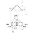
- FIG. 1 is a schematic plan view showing the overall configuration of a ship 2 provided with a ship propulsion device 1.
- FIG. 2 is a block diagram showing an electrical configuration of the ship 2.
- the ship 2 includes a hull 3.
- the ship 2 is provided with a ship propulsion device 1.
- the marine propulsion device 1 includes three or more propulsion devices 11 and a control unit 12. In this embodiment, four propulsion machines (even numbers) are provided.
- the four propulsion machines 11 include a first propulsion machine 11A, a second propulsion machine 11B, a third propulsion machine 11C, and a fourth propulsion machine 11D.
- the number of propulsion machines 11 is not particularly limited, and may be, for example, six or eight.
- the four propulsion machines 11 are provided at the stern of the ship 2. Each of the four propulsion units 11 is attached to the hull 3. The four propulsion machines 11 are arranged in the left-right direction. In the present embodiment, the first propulsion machine 11A, the second propulsion machine 11B, the third propulsion machine 11C, and the fourth propulsion machine 11D are arranged in order from the left side of the hull 3. The four propulsion machines 11 are arranged on both the left and right sides of the hull 3 with the central line 15 passing through the left and right central portions of the hull 3 interposed therebetween.
- propulsion machines 11 Of the four propulsion machines 11, two propulsion machines 11, specifically the first propulsion machine 11A and the second propulsion machine 11B, are arranged on the left side of the hull 3. The remaining two propulsion units 11, specifically the third propulsion unit 11C and the fourth propulsion unit 11D, are arranged on the right side of the hull 3.
- the four propulsion machines 11 are arranged symmetrically in a plan view with the center line 15 as the axis of symmetry. Specifically, the first propulsion machine 11A and the fourth propulsion machine 11D have a symmetrical correspondence relationship, and the second propulsion machine 11B and the third propulsion machine 11C have a symmetrical correspondence relationship.
- Each of the four propulsion machines 11 includes a drive source (engine and electric motor) and a screw. Each propulsion machine 11 can rotate the screw by the driving force of the driving source. The direction of the rotation axis of the screw can be changed around the vertical axis. The direction of the rotation axis of the screw, stop / forward rotation / reverse rotation, and rotation speed are controlled by the control unit 12.
- the control unit 12 can independently change these control parameters for each propulsion machine 11. By controlling each propulsion unit 11 by the control unit 12, it is possible to realize various maneuvers including the movement of the ship 2 in the front-rear direction, the translation in the lateral direction, the in-situ turning, and the like.
- Each propulsion unit 11 can be configured as a stern drive or an outboard motor.
- the configuration of each propulsion machine 11 is not particularly limited. In the present embodiment, the four propulsion machines 11 have substantially the same configuration.
- the control unit 12 is configured as a computer including a CPU, ROM, and RAM. Various programs including a program for operating each propulsion machine 11 are stored in the ROM. The CPU can read various programs and the like from the ROM and execute them. Then, by the cooperation of the above hardware and software, the control unit 12 can be operated as the failure detection unit (abnormality detection unit) 12a shown in FIG.
- the failure detection unit 12a monitors the communication state between the control unit 12 and a predetermined portion of each propulsion unit 11 connected to the control unit 12, and recognizes that a disconnection has occurred in the harness connecting the two based on the communication state. By doing so, it is detected that a failure (abnormality) has occurred in each propulsion machine 11.
- the configuration for the failure detection unit 12a to detect the failure of each propulsion unit 11 is not particularly limited, and for example, each propulsion unit is based on the detection value of the sensor group attached to the drive source of each propulsion unit 11. The failure that occurs in 11 may be detected.
- control unit 12 is connected to each of the four propulsion machines 11, the first propulsion machine 11A, the second propulsion machine 11B, the third propulsion machine 11C, and the fourth propulsion machine 11D. There is.
- the control unit 12 can control each propulsion machine 11 to stop or operate each propulsion machine 11.
- control unit 12 is connected to the first lever position sensor 21, the steering angle sensor 22, and the second lever position sensor 23.
- the first lever position sensor 21 detects the operating position of the throttle lever provided on the ship 2.
- the control unit 12 adjusts the operating state of the drive source of the propulsion machine 11 according to the operating position of the throttle lever operated by the operator (manipulator), and changes the rotation speed of the screw. As a result, the propulsion machine 11 can propel the ship 2.
- the steering angle sensor 22 detects the steering angle of the steering handle provided on the ship 2.
- the second lever position sensor 23 detects the operating position of the ship maneuvering lever provided on the ship 2.
- the control unit 12 changes the rotation angle (direction of the rotation axis of the screw) of the propulsion machine 11 according to the operation amount of the steering handle operated by the operator and / or the operation position of the second lever position sensor 23. As a result, the propulsion machine 11 can turn the ship 2.
- FIG. 3 is a flowchart showing a process in which the control unit 12 controls the propulsion machine 11 based on the output result of the failure detection unit 12a.
- the control unit 12 When the control unit 12 is operating each of the four propulsion machines 11, the first propulsion machine 11A, the second propulsion machine 11B, the third propulsion machine 11C, and the fourth propulsion machine 11D, that is, the ship 2.
- the four propulsion units 11 are controlled based on the output result of the failure detection unit 12a.
- the control unit 12 determines whether or not any of the four propulsion machines 11 has a failure (step S101). This determination is made based on the detection result of the failure detection unit 12a. That is, when the failure detection unit 12a detects that a failure has occurred in the propulsion device 11, the control unit 12 recognizes that the propulsion device 11 has failed.
- step S101 When it is determined that a failure has occurred in any of the four propulsion machines 11 (step S101, Yes), the control unit 12 stops the failed propulsion machine 11 (step S102). On the other hand, when it is determined that no failure has occurred in the four propulsion machines 11 (steps S101 and No), the process returns to step S101.
- the control unit 12 is at least one of the propulsion units 11 arranged on the left side and the right side of the hull 3 with respect to the side on which the failed propulsion unit 11 is arranged.
- the propulsion machine 11 is stopped (step S103).
- the propulsion machine 11 stopped here is a propulsion machine 11 (hereinafter, may be referred to as a normal propulsion machine 11) in which the occurrence of a failure has not been detected.
- the control unit 12 stops the second propulsion machine 11B and then the hull 3 At least one of the third propulsion machine 11C and the fourth propulsion machine 11D on the right side, which are the propulsion machines 11 arranged on the left and right sides of the above, is stopped.
- the propulsion machine 11 having a symmetrical relationship with the propulsion machine 11 is stopped almost at the same time as the failed propulsion machine 11 is stopped.
- the control unit 12 stops the second propulsion machine 11B and also stops the third propulsion machine 11C.
- the propulsion machines 11 that continue to operate are the first propulsion machine 11A and the fourth propulsion machine 11D.
- control unit 12 determines whether or not a failure has occurred in the other propulsion device 11 that continues to operate (step S104).
- step S104 When it is determined that a failure has occurred in any of the other propulsion machines 11 (step S104, Yes), the control unit 12 stops the other propulsion machine 11 (step S105). When it is determined that a failure has newly occurred in the fourth propulsion machine 11D while the second propulsion machine 11B and the third propulsion machine 11C are stopped as in the above example, the control unit 12 determines that a failure has occurred. 4 Stop the operation of the propulsion machine 11D. On the other hand, when it is determined that no failure has occurred in any of the other propulsion machines 11 (steps S104, No), the process returns to step S104.
- the control unit 12 determines whether there are two or more or less than two remaining operating propulsion machines (normal propulsion machines without failure) 11. Determine (step S106). In the present embodiment, the number of propulsion machines 11 is 4, and at the time of step S105, the number of propulsion machines 11 to be stopped is 3 out of the 4 propulsion machines 11. Since the number of the propulsion machines 11 in operation is one, in step S106, the control unit 12 always determines that the number of the remaining propulsion machines 11 in operation is less than two.
- step S108 the control unit 12 determines whether or not there is one propulsion machine 11 in operation. According to the above example, at the time of step S108, the number of propulsion machines 11 in operation is one. Therefore, the determination in step S108 is Yes.
- the control unit 12 continues the operation of one propulsion machine 11 in operation (step S109). That is, in principle, since the fourth propulsion machine 11D has a failure, it is considered that the first propulsion machine 11A on the opposite side to the failure should be stopped, but the only operating first propulsion machine 11A If you stop, you will not be able to navigate. Therefore, in this case, the operation of the first propulsion machine 11A is controlled so as not to be stopped.
- the control unit 12 may restart the normal operation of the propulsion machine 11 that has been stopped.
- the operation of the first propulsion machine 11A is continued in step S109, and the normal operation of the third propulsion machine 11C that was stopped in step S105 is restarted.
- the normal propulsion machine 11 for resuming the operation may be one propulsion machine arranged on the left side and the right side of the hull 3 on the side opposite to the side where the one operating propulsion machine 11 is arranged. preferable.
- the number of propulsion machines 11 is four. Since the operations of the three propulsion machines 11 are stopped from step S101 to step S105, the determination in step S106 is always No. However, when the number of propulsion machines 11 is 5 or more, the determination in step S106 may be Yes. In this case, the control unit 12 stops the operation of the propulsion machine 11 arranged on the opposite side of the failed propulsion machine 11 as in step S103 (step S107). After that, the process returns to step S104.
- the number of propulsion machines 11 is an even number (4). Therefore, if any of the propulsion machines 11 fails and the propulsion machine 11 is stopped together with the corresponding propulsion machine 11, the number of propulsion machines 11 that continue to operate is 4 to 2. In addition, it decreases while keeping an even number.
- the determination in step S108 is Yes. As a result, the process of step S109 described above is performed.
- the number of propulsion machines 11 is an odd number, for example, five.
- the number of propulsion machines 11 that continue to operate is from 5 to 3 or 3. It decreases while keeping an odd number, such as one. If there is only one propulsion machine 11 that continues to operate and a failure occurs in this only propulsion machine 11, the propulsion machine 11 is stopped in step S105. Since the operations of all the propulsion machines 11 have stopped, the determination in step S106 is No, and the determination in step S108 is also No. Therefore, the control unit 12 restarts the operation of at least one normal propulsion machine 11 that has been stopped (step S110).
- step S108 a state in which at least one normal propulsion machine 11 is operating is realized, and propulsion force can be secured. As a result, the navigation of the ship 2 can be continued.
- the marine propulsion device 1 of the present embodiment includes four propulsion devices 11, a failure detection unit 12a, and a control unit 12.
- the four propulsion machines 11 are attached to the hull 3 of the ship 2.
- the failure detection unit 12a can detect that a failure has occurred in each of the four propulsion machines 11.
- the control unit 12 controls four propulsion machines 11.
- the four propulsion machines 11 are arranged symmetrically. When the failure detection unit 12a detects that a failure has occurred in any of the four propulsion units 11 while the control unit 12 is operating the four propulsion units 11, a failure occurs. Stops the propulsion machine 11 in which is detected.
- control unit 12 is arranged on the left side and the right side of the hull 3 among the four propulsion units 11 on the side opposite to the side on which the propulsion unit 11 in which the occurrence of the failure is detected is arranged. Stop at least one propulsion machine 11.
- the propulsion machine 11 arranged on the left and right sides opposite to the propulsion machine 11 is stopped, so that the operator navigates while balancing the left and right propulsion forces. Will be easier to continue.
- At least one propulsion machine that is stopped when the propulsion machine 11 in which the occurrence of the failure is detected is stopped is symmetrical with the propulsion machine 11 in which the occurrence of the failure is detected. Includes the related propulsion machine 11.
- the propulsion machine 11 arranged symmetrically with the propulsion machine 11 in which the occurrence of the failure is detected is stopped, so that it becomes easy to balance the left and right propulsive forces.
- the control unit 12 has found that a failure has occurred in the four propulsion devices 11 other than the propulsion device 11 in which the failure has been detected. Is detected by the failure detection unit 12a, the other propulsion device 11 is stopped. When the number of operating propulsion units 11 becomes one as a result of stopping the other propulsion units 11 for which a failure is newly detected, the control unit 12 operates the propulsion units 11 during the operation. To maintain. In addition to or instead of maintaining the operation of the propulsion machine 11 during the operation, the operation of at least one propulsion machine 11 which has stopped without detecting the occurrence of a failure may be restarted. When the propulsion machine 11 in operation disappears as a result of stopping the propulsion machine 11 in which the failure is newly detected, the control unit 12 determines at least one propulsion machine that is stopped without detecting the occurrence of the failure. The operation of 11 is restarted.
- a failure occurs when the number of operating propulsion devices 11 becomes one as a result of stopping another propulsion device 11 in which a failure is newly detected. Can be modified to resume the operation of at least one propulsion machine 11 that has stopped without being detected. It is preferable that at least one propulsion machine 11 for resuming the operation includes a propulsion machine 11 arranged on the left side and the right side of the hull 3 on the side opposite to the side on which the operating propulsion machine 11 is arranged.
- FIG. 4 is a schematic plan view showing the overall configuration of the ship 2 provided with the ship propulsion device 1x according to the second embodiment.
- the same reference numerals may be given to the same or similar members as those in the above-described embodiment, and the description may be omitted.
- the marine propulsion device 1x of the present embodiment shown in FIG. 4 is different from the marine propulsion device 1 of the first embodiment in that it includes an odd number (5) of propulsion devices 11.
- One of the odd-numbered propulsion machines 11 is arranged at the center of the left and right sides of the hull 3.
- the propulsion machine 11 at the center of the left and right is controlled independently of the other propulsion machines 11.
- the five propulsion machines 11 have a first propulsion machine 11A, a second propulsion machine 11B, a third propulsion machine 11C, a fourth propulsion machine 11D, and a central propulsion machine 11E.
- the five propulsion machines 11 are arranged side by side in the left-right direction as in the first embodiment.
- the central propulsion machine 11E is arranged on the central line 15.
- four other propulsion machines 11 other than the central propulsion machine 11E are arranged on the left and right sides of the hull 3 with the central propulsion machine 11E in between.
- the first propulsion machine 11A and the second propulsion machine 11B are arranged on the left side of the hull 3.
- the third propulsion machine 11C and the fourth propulsion machine 11D are arranged on the right side of the hull 3.
- the first propulsion machine 11A and the fourth propulsion machine 11D have a symmetrical correspondence relationship with respect to the center line 15, and the second propulsion machine 11B and the third propulsion machine 11C have a symmetrical correspondence relationship with respect to the center line 15. Therefore, the five propulsion machines 11 are symmetrical.
- the central propulsion machine 11E is connected to the control unit 12 to which the four other propulsion machines 11 are connected.
- the control unit 12 controls the central propulsion machine 11E, and can stop or operate the central propulsion machine 11E.
- the central propulsion machine 11E is controlled by the control unit 12 independently of the other four propulsion machines 11. In other words, the central propulsion machine 11E is controlled regardless of the control status of the four other propulsion machines 11.
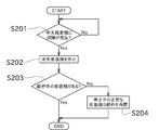
- FIG. 6 is a flowchart showing a process in which the control unit 12 controls the central propulsion machine 11E based on the output result of the failure detection unit 12a.
- the control unit 12 controls the four other propulsion units 11 other than the central propulsion unit 11E out of the five propulsion units 11 based on the output result of the failure detection unit 12a, as in the first embodiment. Do. Further, the control unit 12 controls the central propulsion machine 11E separately from the control of the other propulsion machines 11 during the operation of the central propulsion machine 11E.
- the control unit 12 determines whether or not a failure has occurred in the central propulsion machine 11E (step S201). This determination is made based on the detection result of the failure detection unit 12a. That is, when the failure detection unit 12a detects that a failure has occurred in the central propulsion machine 11E, the control unit 12 recognizes that the central propulsion machine 11E has failed.
- step S201 If it is determined that no failure has occurred in the central propulsion machine 11E (steps S201, No), the process returns to step S201.
- step S201 When it is determined that the central propulsion machine 11E has a failure (step S201, Yes), the control unit 12 stops the central propulsion machine 11E (step S202).
- control unit 12 determines whether or not there is a propulsion machine 11 in operation (step S203). That is, with respect to the four other propulsion machines 11, it is determined whether or not there is a propulsion machine 11 that has not been stopped.
- step S203 When it is determined that there is a propulsion machine 11 in operation (step S203, Yes), the control unit 12 ends the process. When it is determined that there is no propulsion machine 11 in operation (step S203, No), the control unit 12 restarts the operation of at least one normal propulsion machine 11 that is stopped (step S204). As a result, the propulsive force for the ship 2 can be reliably secured.
- the marine propulsion device 1x of the present embodiment includes an odd number (5) of propulsion devices 11.
- the central propulsion machine 11E which is one of the five propulsion machines 11, is arranged at the left and right central portions of the hull 3.
- the control unit 12 controls the central propulsion machine 11E independently of the other propulsion machines 11 among the five propulsion machines 11.
- the central propulsion machine 11E can be controlled. Therefore, the other propulsion device 11 can easily balance the left and right propulsive forces while continuing the navigation. Further, the strength of the propulsive force can be adjusted by the central propulsion machine 11E.
- the control unit 12 stops the central propulsion machine 11E when the failure detection unit 12a detects that a failure has occurred in the central propulsion machine 11E.
- the control unit 12 restarts the operation of at least one normal propulsion machine 11 that is stopped.
- At least one propulsion machine 11 can generate propulsive force to continue the navigation.
- the number of propulsion machines 11 is arbitrary as long as it is 3 or more, and may be an even number or an odd number.
- one propulsion machine 11 arranged at the left and right central portions of the hull 3 does not have to be controlled independently of the other propulsion machines 11.
- the state in which three or more propulsion units 11 are arranged symmetrically on the hull 3 refers only to a state in which one propulsion unit 11 is arranged symmetrically with respect to the other propulsion unit 11. However, it includes a state in which one propulsion machine 11 is arranged at a position slightly deviated from an accurate symmetrical position with respect to the other propulsion machine 11.
- the marine propulsion device 1 is provided with, for example, four propulsion machines 11, and since one of the propulsion machines 11 has a failure, the number of propulsion machines 11 that continue to operate is from four to two as in the above example. Suppose that the number is reduced to one. After that, consider a case where a failure occurs in any of the two operating propulsion machines 11 and the propulsion machine 11 is stopped, resulting in only one operating propulsion machine 11 remaining. In this case, both the failed propulsion machine 11 and the operating propulsion machine 11 may be stopped, and instead, the operation of at least one stopped normal propulsion machine 11 may be restarted.
- a propulsion machine 11 located closer to the center of the left and right sides of the hull 3 than the propulsion machine 11 which was normal and in operation is selected, thereby balancing the left and right sides. It is preferable because it can be easily obtained.
- the flowchart of FIG. 3 can handle both the case where the number of propulsion machines 11 is an even number and the case where the number of propulsion machines 11 is an odd number.
- This flowchart can be changed to a flowchart specialized when the number of propulsion machines 11 is an even number, or can be changed to a flowchart specialized when the number of propulsion machines 11 is an even number.
Abstract
A ship propulsion device (1) includes three or more propulsion units (11), a malfunction detection unit (12a), and a control unit (12). The control unit (12) controls the three or more propulsion units (11). The three or more propulsion units (11) are disposed with left-right symmetry. When a malfunction is detected in any one of the three or more propulsion units (11) by the malfunction detection unit (12a) while the three or more propulsion units (11) are operating, the control unit (12) stops the propulsion unit (11) in which the malfunction has been detected, and, on a left side and a right side of a hull, stops at least one propulsion unit (11)\ of the propulsion units (11) disposed on the side opposite from the side on which the propulsion unit (11) in which the malfunction has been detected is disposed.
Description
本発明は、船舶用推進装置に関する。
The present invention relates to a marine propulsion device.
従来から、複数の推進機を備えた船舶用の推進装置が知られている。特許文献1は、この種の推進装置である複数の船外機を開示する。
Conventionally, propulsion devices for ships equipped with a plurality of propulsion machines have been known. Patent Document 1 discloses a plurality of outboard motors that are propulsion devices of this type.
特許文献1の構成では、3つの船外機が設けられている。これらの船外機は、船舶の船尾に並べて取り付けられており、左右方向の揺動(転舵)が可能な状態とされている。各船外機は、エンジン及びプロペラを備え、エンジンの駆動力によってプロペラを回転させることで推進力を発生させる。そして、各船外機が操舵装置によって転舵角を制御されることにより、推進力の方向が変化し、それに応じて船舶の進行方向が変更されるようになっている。
In the configuration of Patent Document 1, three outboard motors are provided. These outboard motors are installed side by side at the stern of the ship, and are in a state where they can swing (steer) in the left-right direction. Each outboard motor is equipped with an engine and a propeller, and a propulsive force is generated by rotating the propeller by the driving force of the engine. Then, the direction of the propulsive force is changed by controlling the steering angle of each outboard motor by the steering device, and the traveling direction of the ship is changed accordingly.
操舵装置は、メインECU及び転舵用ECUを含む。転舵用ECUは、各船外機の転舵角制御に故障が発生したか否かを監視する。何れかの船外機の転舵角制御に故障が発生した場合には、転舵用ECUからメインECUにその旨が通知される。これにより、メインECUは、何れかの船外機の転舵角制御に故障が発生したことを検出し、かつ転舵角制御に故障が発生した船外機を認識する。また、メインECUは、船外機ECUを用いてエンジン回転速度を制御する。
The steering device includes a main ECU and a steering ECU. The steering ECU monitors whether or not a failure has occurred in the steering angle control of each outboard motor. If a failure occurs in the steering angle control of any of the outboard motors, the steering ECU notifies the main ECU to that effect. As a result, the main ECU detects that a failure has occurred in the steering angle control of any of the outboard motors, and recognizes the outboard motor in which the steering angle control has a failure. Further, the main ECU controls the engine rotation speed by using the outboard motor ECU.
メインECUは、何れかの船外機の転舵角制御に故障が発生した場合、故障が発生している船外機(故障船外機)について、当該故障船外機による推進力の発生を強制的に停止させるための処理を行う。具体的には、メインECUは、故障船外機のエンジン回転速度を所定のアイドル回転速度に固定する。また、メインECUは、正常な他の船外機(転舵角制御に故障が発生していない船外機)のエンジン回転速度を所定の制限速度以下に制限する。
When a failure occurs in the steering angle control of any of the outboard motors, the main ECU generates propulsive force by the failed outboard motor for the failed outboard motor (failed outboard motor). Performs processing for forcibly stopping. Specifically, the main ECU fixes the engine rotation speed of the failed outboard motor to a predetermined idle rotation speed. Further, the main ECU limits the engine rotation speed of another normal outboard motor (outboard motor in which the steering angle control has not failed) to a predetermined speed limit or less.
上記特許文献1の構成は、何れかの船外機の転舵角制御に故障が発生した場合、故障船外機による推進力の発生を強制的に停止させ、一方で、正常な他の船外機全てによる推進力の発生は維持させる。従って、船尾における故障船外機の位置によっては、船外機が発生させる推進力の左右バランスが崩れた状態で航行が続行されることになる。例えば、最も左側に取り付けられた推進機に故障が発生した場合には、正常な他の船外機である、最も右側に取り付けられた推進機と、左右中央に配置された推進機と、による推進力を用いて航行を行うことになる。従って、船外機の故障発生後、航行が困難となるおそれがある。
The configuration of Patent Document 1 is that when a failure occurs in the steering angle control of any of the outboard motors, the generation of propulsive force by the failed outboard motor is forcibly stopped, while the other normal ship. Maintain the generation of propulsion by all external units. Therefore, depending on the position of the failed outboard motor at the stern, the navigation will be continued in a state where the left-right balance of the propulsive force generated by the outboard motor is lost. For example, if the propeller mounted on the leftmost side fails, it depends on the other normal outboard motors, the propulsion machine mounted on the rightmost side and the propulsion machine placed in the center of the left and right. It will sail using propulsion. Therefore, navigation may become difficult after the outboard motor fails.
本発明は以上の事情に鑑みてされたものであり、その目的は、3個以上の推進機を備える船舶用推進装置を用いて船舶が航行する場合に、何れかの推進機に異常が発生したとき、当該船舶用推進装置が発生させる推進力に関し左右の推進力のバランスをとり易くして、航行の継続を容易にする船舶用推進装置を提供することにある。
The present invention has been made in view of the above circumstances, and an object of the present invention is that when a ship navigates by using a marine propulsion device equipped with three or more propulsion devices, an abnormality occurs in any of the propulsion devices. At that time, it is an object of the present invention to provide a marine propulsion device that facilitates the balance of the left and right propulsive forces with respect to the propulsive force generated by the marine propulsion device and facilitates the continuation of navigation.
本発明の解決しようとする課題は以上の如くであり、次にこの課題を解決するための手段とその効果を説明する。
The problem to be solved by the present invention is as described above, and next, the means for solving this problem and its effect will be described.
本発明の観点によれば、以下の構成の船舶用推進装置が提供される。即ち、この船舶用推進装置は、3個以上の推進機と、異常検出部と、制御部と、を備える。3個以上の前記推進機は、船舶の船体に取り付けられる。前記異常検出部は、前記3個以上の推進機のそれぞれに異常が発生したことを検出可能である。前記制御部は、前記3個以上の推進機を制御する。前記3個以上の推進機は、左右対称に配置される。前記制御部は、前記3個以上の推進機を動作させている状態で、前記3個以上の推進機のうち何れかの推進機に異常が発生したことが前記異常検出部により検出された場合に、異常の発生が検出された推進機を停止させ、前記3個以上の推進機のうち、前記船体の左側及び右側において、前記異常の発生が検出された推進機が配置された側と反対側に配置されている少なくとも1個の推進機を停止させる。
From the viewpoint of the present invention, a marine propulsion device having the following configuration is provided. That is, this marine propulsion device includes three or more propulsion machines, an abnormality detection unit, and a control unit. Three or more of the propulsion machines are attached to the hull of a ship. The abnormality detection unit can detect that an abnormality has occurred in each of the three or more propulsion machines. The control unit controls the three or more propulsion machines. The three or more propulsion machines are arranged symmetrically. When the abnormality detection unit detects that an abnormality has occurred in any of the three or more propulsion machines while the control unit is operating the three or more propulsion machines. The propulsion machine in which the occurrence of the abnormality was detected was stopped, and the propulsion machine in which the occurrence of the abnormality was detected was placed on the left side and the right side of the hull among the three or more propulsion machines. Stop at least one propulsion machine located on the side.
これにより、推進機に異常が発生したことが検出された場合、当該推進機と左右反対側に配置された推進機を停止させるので、オペレータが左右の推進力のバランスをとりながら航行を継続することが容易になる。
As a result, when it is detected that an abnormality has occurred in the propulsion machine, the propulsion machine located on the left and right sides of the propulsion machine is stopped, so that the operator continues navigation while balancing the left and right propulsion forces. It becomes easy.
前記の船舶用推進装置においては、前記異常の発生が検出された推進機の停止に伴い停止させられる前記少なくとも1個の推進機は、前記異常の発生が検出された推進機と左右対称の関係にある推進機を含むことが好ましい。
In the marine propulsion device, at least one propulsion machine that is stopped when the propulsion machine in which the occurrence of the abnormality is detected is stopped has a symmetrical relationship with the propulsion machine in which the occurrence of the abnormality is detected. It is preferable to include the propulsion machine in.
これにより、異常の発生が検出された推進機と左右対称に配置された推進機を停止させるので、左右の推進力のバランスをとり易くなる。
As a result, the propulsion units arranged symmetrically with the propulsion unit in which the occurrence of the abnormality is detected are stopped, so that it becomes easy to balance the left and right propulsion forces.
前記の船舶用推進装置においては、以下の構成とすることが好ましい。即ち、前記制御部は、前記3個以上の推進機に関して、前記異常の発生が検出された推進機以外の動作中の他の推進機に異常が発生したことが前記異常検出部により検出されたとき、当該他の推進機を停止させる。前記他の推進機を停止させた結果、動作中の推進機の数が1個になる場合には、前記制御部は、当該動作中の推進機の動作を維持させ、及び/又は、異常の発生が検出されずに停止中の少なくとも1個の推進機の動作を再開させる。動作中の推進機が無くなる場合には、前記制御部は、異常の発生が検出されずに停止中の少なくとも1個の推進機の動作を再開させる。
The marine propulsion device described above preferably has the following configuration. That is, with respect to the three or more propulsion units, the control unit has detected that an abnormality has occurred in other operating propulsion machines other than the propulsion machine in which the occurrence of the abnormality has been detected. At that time, the other propulsion machine is stopped. When the number of propulsion units in operation becomes one as a result of stopping the other propulsion units, the control unit keeps the operation of the propulsion units in operation and / or abnormal. The operation of at least one propulsion machine that has been stopped without being detected is restarted. When the operating propulsion unit disappears, the control unit restarts the operation of at least one stopped propulsion unit without detecting the occurrence of an abnormality.
これにより、異常の発生が検出された推進機が増えてきた場合でも、推進力を発生させる推進機の動作を確保して、航行を継続することができる。
As a result, even if the number of propulsion machines in which the occurrence of an abnormality is detected increases, it is possible to secure the operation of the propulsion machine that generates the propulsive force and continue the navigation.
前記の船舶用推進装置においては、以下の構成とすることができる。即ち、前記制御部は、前記他の推進機を停止させた結果、前記動作中の推進機の数が1個になる場合に、当該動作中の推進機の動作を維持させるとともに、異常の発生が検出されずに停止中の少なくとも1個の推進機の動作を再開させる。前記動作を再開させる少なくとも1個の推進機は、前記船体の左側及び右側において、前記動作中の推進機が配置された側と反対側に配置されている推進機を含む。
The above-mentioned marine propulsion device can have the following configuration. That is, when the number of propulsion machines in operation becomes one as a result of stopping the other propulsion machines, the control unit maintains the operation of the propulsion machines in operation and causes an abnormality. Is not detected and the operation of at least one propulsion machine that has been stopped is restarted. The at least one propulsion machine that resumes the operation includes a propulsion machine that is arranged on the left side and the right side of the hull on the side opposite to the side where the operating propulsion machine is arranged.
これにより、左右の推進力のバランスの改善を図ることができる。
This makes it possible to improve the balance of left and right propulsive forces.
前記の船舶用推進装置においては、以下の構成とすることができる。即ち、前記制御部は、前記他の推進機を停止させた結果、前記動作中の推進機の数が1個になる場合に、当該動作中の推進機の動作を停止させるとともに、異常の発生が検出されずに停止中の少なくとも1個の推進機の動作を再開させる。
The above-mentioned marine propulsion device can have the following configuration. That is, when the number of propulsion machines in operation becomes one as a result of stopping the other propulsion machines, the control unit stops the operation of the propulsion machines in operation and causes an abnormality. Is not detected and the operation of at least one propulsion machine that has been stopped is restarted.
これにより、例えば、1個になった動作中の推進機に代えて、当該推進機よりも船体の左右中央部寄りに配置された推進機を動作させることができる。これにより、左右の推進力のバランスの改善を図ることができる。
Thereby, for example, instead of one operating propulsion machine, a propulsion machine arranged closer to the center of the left and right sides of the hull than the propulsion machine can be operated. As a result, the balance between the left and right propulsive forces can be improved.
前記の船舶用推進装置においては、以下の構成とすることが好ましい。即ち、この船舶用推進装置は、前記推進機を奇数個備える。前記3個以上の推進機のうちの1個の推進機は、前記船体の左右中央部に配置される。前記制御部は、前記船体の左右中央部に配置された前記1個の推進機を、前記3個以上の推進機のうちの他の推進機とは独立して制御する。
The marine propulsion device described above preferably has the following configuration. That is, this marine propulsion device includes an odd number of the propulsion machines. One of the three or more propulsion machines is arranged at the center of the left and right sides of the hull. The control unit controls the one propulsion machine arranged at the left and right central portions of the hull independently of the other propulsion machines among the three or more propulsion machines.
これにより、他の推進機に関して、異常の発生が検出された推進機とこれに対応する推進機を停止させたとしても、船体の左右中央部に配置された1個の推進機の制御を行うことができる。従って、他の推進機によって左右の推進力のバランスを容易にとりながら航行を継続することができる。また、前記船体の左右中央部に配置された1個の推進機によって推進力の強弱を調整することができる。
As a result, even if the propulsion machine in which the occurrence of an abnormality is detected and the propulsion machine corresponding to the other propulsion machine are stopped, one propulsion machine arranged in the center left and right of the hull is controlled. be able to. Therefore, it is possible to continue the navigation while easily balancing the left and right propulsive forces with another propulsion machine. Further, the strength of the propulsive force can be adjusted by one propulsion machine arranged at the center of the left and right sides of the hull.
前記の船舶用推進装置においては、以下の構成とすることが好ましい。即ち、前記制御部は、前記船体の左右中央部に配置された前記1個の推進機に異常が発生したことが前記異常検出部により検出されたとき、当該1個の推進機を停止させる。前記1個の推進機を停止させた結果、動作中の推進機が無くなる場合には、前記制御部は、異常が検出されずに停止中の少なくとも1個の推進機の動作を再開させる。
The marine propulsion device described above preferably has the following configuration. That is, the control unit stops the one propulsion machine when the abnormality detection unit detects that an abnormality has occurred in the one propulsion machine arranged at the left and right center portions of the hull. When the operating propulsion machine disappears as a result of stopping the one propulsion machine, the control unit restarts the operation of the stopped propulsion machine without detecting an abnormality.
これにより、船体の左右中央部に配置された1個の推進機が停止した場合であっても、少なくとも1個の推進機により推進力を発生させて、航行を継続することができる。
As a result, even if one propulsion unit arranged at the center of the left and right sides of the hull stops, at least one propulsion unit can generate propulsive force and continue navigation.
次に、図面を参照して本発明の実施の形態を説明する。初めに、本発明の第1実施形態に係る船舶用推進装置1について説明する。図1は、船舶用推進装置1が設けられた船舶2の全体的な構成を示す概略平面図である。図2は、船舶2の電気的な構成を示すブロック図である。
Next, an embodiment of the present invention will be described with reference to the drawings. First, the marine propulsion device 1 according to the first embodiment of the present invention will be described. FIG. 1 is a schematic plan view showing the overall configuration of a ship 2 provided with a ship propulsion device 1. FIG. 2 is a block diagram showing an electrical configuration of the ship 2.
図1に示すように、船舶2は、船体3を備える。この船舶2に、船舶用推進装置1が設けられている。
As shown in FIG. 1, the ship 2 includes a hull 3. The ship 2 is provided with a ship propulsion device 1.
船舶用推進装置1は、3個以上の推進機11と、制御部12と、を備える。本実施形態では、推進機11は4個(偶数個)備えられている。4個の推進機11は、第1推進機11Aと、第2推進機11Bと、第3推進機11Cと、第4推進機11Dと、を有する。なお、推進機11の数は、特に限定されず、例えば6個でもよいし、8個でもよい。
The marine propulsion device 1 includes three or more propulsion devices 11 and a control unit 12. In this embodiment, four propulsion machines (even numbers) are provided. The four propulsion machines 11 include a first propulsion machine 11A, a second propulsion machine 11B, a third propulsion machine 11C, and a fourth propulsion machine 11D. The number of propulsion machines 11 is not particularly limited, and may be, for example, six or eight.
4個の推進機11は、船舶2の船尾に設けられている。4個の推進機11は、それぞれ、船体3に取り付けられている。4個の推進機11は、左右方向に並べられている。本実施形態では、第1推進機11Aと、第2推進機11Bと、第3推進機11Cと、第4推進機11Dとが、船体3の左側から順に配置されている。4個の推進機11は、船体3の左右中央部を通る中央線15を挟んで、当該船体3の左右両側に振り分けて配置されている。
The four propulsion machines 11 are provided at the stern of the ship 2. Each of the four propulsion units 11 is attached to the hull 3. The four propulsion machines 11 are arranged in the left-right direction. In the present embodiment, the first propulsion machine 11A, the second propulsion machine 11B, the third propulsion machine 11C, and the fourth propulsion machine 11D are arranged in order from the left side of the hull 3. The four propulsion machines 11 are arranged on both the left and right sides of the hull 3 with the central line 15 passing through the left and right central portions of the hull 3 interposed therebetween.
4個の推進機11のうち2個の推進機11、具体的には第1推進機11A及び第2推進機11Bが、船体3の左側に配置されている。残りの2個の推進機11、具体的には第3推進機11C及び第4推進機11Dが、船体3の右側に配置されている。そして、4個の推進機11は、中央線15を対称軸として、平面視で左右対称に配置されている。具体的には、第1推進機11Aと第4推進機11Dとが左右対称の対応関係にあり、第2推進機11Bと第3推進機11Cとが左右対称の対応関係にある。
Of the four propulsion machines 11, two propulsion machines 11, specifically the first propulsion machine 11A and the second propulsion machine 11B, are arranged on the left side of the hull 3. The remaining two propulsion units 11, specifically the third propulsion unit 11C and the fourth propulsion unit 11D, are arranged on the right side of the hull 3. The four propulsion machines 11 are arranged symmetrically in a plan view with the center line 15 as the axis of symmetry. Specifically, the first propulsion machine 11A and the fourth propulsion machine 11D have a symmetrical correspondence relationship, and the second propulsion machine 11B and the third propulsion machine 11C have a symmetrical correspondence relationship.
4個の推進機11は、それぞれ、駆動源(エンジンや電動モータ)と、スクリューと、を備える。各推進機11は、駆動源の駆動力によりスクリューを回転させることができる。スクリューの回転軸の向きは、上下方向の軸を中心として変更可能である。スクリューの回転軸の向き、停止/正転/逆転、及び回転速度は、制御部12により制御される。制御部12は、これらの制御パラメータを、推進機11毎に独立して変更することができる。制御部12が各推進機11を制御することによって、船舶2の前後方向の移動、横方向の平行移動、その場旋回等を含めた様々な操船を実現することができる。
Each of the four propulsion machines 11 includes a drive source (engine and electric motor) and a screw. Each propulsion machine 11 can rotate the screw by the driving force of the driving source. The direction of the rotation axis of the screw can be changed around the vertical axis. The direction of the rotation axis of the screw, stop / forward rotation / reverse rotation, and rotation speed are controlled by the control unit 12. The control unit 12 can independently change these control parameters for each propulsion machine 11. By controlling each propulsion unit 11 by the control unit 12, it is possible to realize various maneuvers including the movement of the ship 2 in the front-rear direction, the translation in the lateral direction, the in-situ turning, and the like.
各推進機11は、スターンドライブ又は船外機として構成することができる。なお、各推進機11の構成は特に限定されない。本実施形態では、4つの推進機11は、実質的に同じ構成である。
Each propulsion unit 11 can be configured as a stern drive or an outboard motor. The configuration of each propulsion machine 11 is not particularly limited. In the present embodiment, the four propulsion machines 11 have substantially the same configuration.
制御部12は、CPU、ROM及びRAMを備えるコンピュータとして構成されている。ROMには、各推進機11を動作させるためのプログラムを含む各種プログラム等が記憶される。CPUは、各種プログラム等をROMから読み出して実行することができる。そして、上記のハードウェアとソフトウェアの協働により、制御部12を、図2に示す故障検出部(異常検出部)12aとして動作させることができる。
The control unit 12 is configured as a computer including a CPU, ROM, and RAM. Various programs including a program for operating each propulsion machine 11 are stored in the ROM. The CPU can read various programs and the like from the ROM and execute them. Then, by the cooperation of the above hardware and software, the control unit 12 can be operated as the failure detection unit (abnormality detection unit) 12a shown in FIG.
故障検出部12a、各推進機11に故障(異常)が発生しているか否かを検出する。例えば、故障検出部12aは、制御部12とこれに接続された各推進機11の所定部分との通信状態を監視し、通信状態に基づいて両者を接続するハーネスに断線が発生したことを認識することで、各推進機11に故障(異常)が発生したことを検出する。なお、故障検出部12aが各推進機11の故障を検出するための構成は、特に限定されず、例えば各推進機11の駆動源に取り付けられたセンサ群の検出値に基づいて、各推進機11に発生する故障を検出するようにしてもよい。
Detects whether or not a failure (abnormality) has occurred in the failure detection unit 12a and each propulsion device 11. For example, the failure detection unit 12a monitors the communication state between the control unit 12 and a predetermined portion of each propulsion unit 11 connected to the control unit 12, and recognizes that a disconnection has occurred in the harness connecting the two based on the communication state. By doing so, it is detected that a failure (abnormality) has occurred in each propulsion machine 11. The configuration for the failure detection unit 12a to detect the failure of each propulsion unit 11 is not particularly limited, and for example, each propulsion unit is based on the detection value of the sensor group attached to the drive source of each propulsion unit 11. The failure that occurs in 11 may be detected.
図2に示すように、制御部12は、4個の推進機11である第1推進機11A、第2推進機11B、第3推進機11C、及び第4推進機11Dのそれぞれと接続されている。制御部12は、各推進機11を制御し、各推進機11を停止させたり、動作させたりすることができる。
As shown in FIG. 2, the control unit 12 is connected to each of the four propulsion machines 11, the first propulsion machine 11A, the second propulsion machine 11B, the third propulsion machine 11C, and the fourth propulsion machine 11D. There is. The control unit 12 can control each propulsion machine 11 to stop or operate each propulsion machine 11.
また、制御部12は、第1レバー位置センサ21、操舵角センサ22、及び第2レバー位置センサ23と接続されている。
Further, the control unit 12 is connected to the first lever position sensor 21, the steering angle sensor 22, and the second lever position sensor 23.
第1レバー位置センサ21は、船舶2に設けられたスロットルレバーの操作位置を検出する。制御部12は、オペレータ(操船者)が操作したスロットルレバーの操作位置に応じて、推進機11の駆動源の運転状態を調節し、スクリューの回転速度を変更する。これにより、推進機11は、船舶2を推進させることができる。
The first lever position sensor 21 detects the operating position of the throttle lever provided on the ship 2. The control unit 12 adjusts the operating state of the drive source of the propulsion machine 11 according to the operating position of the throttle lever operated by the operator (manipulator), and changes the rotation speed of the screw. As a result, the propulsion machine 11 can propel the ship 2.
操舵角センサ22は、船舶2に設けられた操舵ハンドルの操舵角を検出する。第2レバー位置センサ23は、船舶2に設けられた操船レバーの操作位置を検出する。制御部12は、オペレータが操作した操舵ハンドルの操作量及び/又は第2レバー位置センサ23の操作位置に応じて、推進機11の回動角度(スクリューの回転軸の向き)を変更する。これにより、推進機11は、船舶2を旋回させることができる。
The steering angle sensor 22 detects the steering angle of the steering handle provided on the ship 2. The second lever position sensor 23 detects the operating position of the ship maneuvering lever provided on the ship 2. The control unit 12 changes the rotation angle (direction of the rotation axis of the screw) of the propulsion machine 11 according to the operation amount of the steering handle operated by the operator and / or the operation position of the second lever position sensor 23. As a result, the propulsion machine 11 can turn the ship 2.
次に、図3を参照して、制御部12が故障検出部12aの出力結果に基づいて推進機11を制御する処理について詳細に説明する。図3は、制御部12が故障検出部12aの出力結果に基づいて推進機11を制御する処理を示すフローチャートである。
Next, with reference to FIG. 3, a process in which the control unit 12 controls the propulsion machine 11 based on the output result of the failure detection unit 12a will be described in detail. FIG. 3 is a flowchart showing a process in which the control unit 12 controls the propulsion machine 11 based on the output result of the failure detection unit 12a.
制御部12は、4個の推進機11である第1推進機11A、第2推進機11B、第3推進機11C、及び第4推進機11Dのそれぞれを動作させているとき、即ち船舶2の航行が行われているとき、故障検出部12aの出力結果に基づいて4個の推進機11の制御を行う。
When the control unit 12 is operating each of the four propulsion machines 11, the first propulsion machine 11A, the second propulsion machine 11B, the third propulsion machine 11C, and the fourth propulsion machine 11D, that is, the ship 2. When navigating, the four propulsion units 11 are controlled based on the output result of the failure detection unit 12a.
まず、制御部12は、4個の推進機11について何れかの推進機11に故障が発生しているか否かを判定する(ステップS101)。この判定は、故障検出部12aの検出結果に基づいて行われる。即ち、故障検出部12aにより推進機11に故障が発生したことが検出されると、制御部12は当該推進機11が故障したと認識する。
First, the control unit 12 determines whether or not any of the four propulsion machines 11 has a failure (step S101). This determination is made based on the detection result of the failure detection unit 12a. That is, when the failure detection unit 12a detects that a failure has occurred in the propulsion device 11, the control unit 12 recognizes that the propulsion device 11 has failed.
4個の推進機11のうち、何れかの推進機11に故障が発生したと判定した場合(ステップS101,Yes)、制御部12は、故障した推進機11を停止させる(ステップS102)。一方、4個の推進機11に故障が発生していないと判定した場合(ステップS101,No)、処理はステップS101に戻る。
When it is determined that a failure has occurred in any of the four propulsion machines 11 (step S101, Yes), the control unit 12 stops the failed propulsion machine 11 (step S102). On the other hand, when it is determined that no failure has occurred in the four propulsion machines 11 (steps S101 and No), the process returns to step S101.
故障した推進機11を停止させた後、制御部12は、船体3の左側及び右側において故障した推進機11が配置された側に対して他方側に配置された推進機11の少なくとも1個の推進機11を停止させる(ステップS103)。ここで停止させられる推進機11は、故障の発生が検出されていない推進機11(以下、正常な推進機11と呼ぶ場合がある。)である。例えば、制御部12は、船体3の左右一側に配置された推進機11である左側の第2推進機11Bが故障した場合には、当該第2推進機11Bを停止させた後、船体3の左右他側に配置された推進機11である右側の第3推進機11C及び第4推進機11Dの少なくとも一方を停止させる。
After stopping the failed propulsion unit 11, the control unit 12 is at least one of the propulsion units 11 arranged on the left side and the right side of the hull 3 with respect to the side on which the failed propulsion unit 11 is arranged. The propulsion machine 11 is stopped (step S103). The propulsion machine 11 stopped here is a propulsion machine 11 (hereinafter, may be referred to as a normal propulsion machine 11) in which the occurrence of a failure has not been detected. For example, when the second propulsion machine 11B on the left side, which is the propulsion machine 11 arranged on the left and right sides of the hull 3, fails, the control unit 12 stops the second propulsion machine 11B and then the hull 3 At least one of the third propulsion machine 11C and the fourth propulsion machine 11D on the right side, which are the propulsion machines 11 arranged on the left and right sides of the above, is stopped.
本実施形態では、故障した推進機11を停止させるのとほぼ同時に、当該推進機11と左右対称の関係にある推進機11が停止される。前述のように第2推進機11Bが故障した例では、制御部12は、第2推進機11Bを停止させるとともに、第3推進機11Cを停止させる。この結果、動作を継続する推進機11は、第1推進機11A及び第4推進機11Dとなる。
In the present embodiment, the propulsion machine 11 having a symmetrical relationship with the propulsion machine 11 is stopped almost at the same time as the failed propulsion machine 11 is stopped. In the example in which the second propulsion machine 11B fails as described above, the control unit 12 stops the second propulsion machine 11B and also stops the third propulsion machine 11C. As a result, the propulsion machines 11 that continue to operate are the first propulsion machine 11A and the fourth propulsion machine 11D.
次に、制御部12は、動作を継続している他の推進機11に故障が発生しているか否かを判定する(ステップS104)。
Next, the control unit 12 determines whether or not a failure has occurred in the other propulsion device 11 that continues to operate (step S104).
他の推進機11の何れかに故障が発生していると判定した場合(ステップS104,Yes)、制御部12は、当該他の推進機11を停止させる(ステップS105)。上述の例のように第2推進機11Bと第3推進機11Cが停止している状態で、新たに第4推進機11Dに故障が発生していると判定した場合、制御部12は、第4推進機11Dの動作を停止させる。一方、他の推進機11の何れにも故障が発生していないと判定した場合(ステップS104,No)、処理はステップS104に戻る。
When it is determined that a failure has occurred in any of the other propulsion machines 11 (step S104, Yes), the control unit 12 stops the other propulsion machine 11 (step S105). When it is determined that a failure has newly occurred in the fourth propulsion machine 11D while the second propulsion machine 11B and the third propulsion machine 11C are stopped as in the above example, the control unit 12 determines that a failure has occurred. 4 Stop the operation of the propulsion machine 11D. On the other hand, when it is determined that no failure has occurred in any of the other propulsion machines 11 (steps S104, No), the process returns to step S104.
故障した他の推進機11を停止させた後、制御部12は、残りの動作中の推進機(故障が発生していない正常な推進機)11が2個以上あるか、2個未満かを判定する(ステップS106)。本実施形態では、推進機11の数は4個であり、ステップS105の時点で、4個のうち停止する推進機11の数が3個となっている。動作している推進機11の数は1個であるから、ステップS106では必ず、制御部12は、残りの動作中の推進機11が2個未満であると判定することになる。
After stopping the other failed propulsion machine 11, the control unit 12 determines whether there are two or more or less than two remaining operating propulsion machines (normal propulsion machines without failure) 11. Determine (step S106). In the present embodiment, the number of propulsion machines 11 is 4, and at the time of step S105, the number of propulsion machines 11 to be stopped is 3 out of the 4 propulsion machines 11. Since the number of the propulsion machines 11 in operation is one, in step S106, the control unit 12 always determines that the number of the remaining propulsion machines 11 in operation is less than two.
動作中の推進機11が2個未満であると判定した場合(ステップS106,No)、制御部12は、動作中の推進機11が1個あるか否かを判定する(ステップS108)。上述の例に従えば、ステップS108の時点で、動作している推進機11の数が1個である。従って、ステップS108の判断はYesになる。
When it is determined that there are less than two propulsion machines 11 in operation (steps S106, No), the control unit 12 determines whether or not there is one propulsion machine 11 in operation (step S108). According to the above example, at the time of step S108, the number of propulsion machines 11 in operation is one. Therefore, the determination in step S108 is Yes.
動作中の推進機11が1個あると判定した場合、制御部12は、当該動作中の1個の推進機11の動作を継続させる(ステップS109)。即ち、原則としては、第4推進機11Dに故障が発生しているので、それと左右反対側にある第1推進機11Aを停止させるべきとも考えられるが、唯一動作している第1推進機11Aを停止させると航行不能になってしまう。従って、この場合は、第1推進機11Aの動作を停止させないように制御する。
When it is determined that there is one propulsion machine 11 in operation, the control unit 12 continues the operation of one propulsion machine 11 in operation (step S109). That is, in principle, since the fourth propulsion machine 11D has a failure, it is considered that the first propulsion machine 11A on the opposite side to the failure should be stopped, but the only operating first propulsion machine 11A If you stop, you will not be able to navigate. Therefore, in this case, the operation of the first propulsion machine 11A is controlled so as not to be stopped.
ステップS109で推進機11の動作を継続する場合に、制御部12により、停止中の正常な推進機11の動作を再開させてもよい。上述の例に従えば、ステップS109で第1推進機11Aの動作を継続するとともに、ステップS105で停止していた正常な第3推進機11Cの動作を再開させる。動作を再開させる正常な推進機11は、船体3の左側及び右側において、動作中の1個の推進機11が配置された側と反対側に配置されている1個の推進機であることが好ましい。
When the operation of the propulsion machine 11 is continued in step S109, the control unit 12 may restart the normal operation of the propulsion machine 11 that has been stopped. According to the above example, the operation of the first propulsion machine 11A is continued in step S109, and the normal operation of the third propulsion machine 11C that was stopped in step S105 is restarted. The normal propulsion machine 11 for resuming the operation may be one propulsion machine arranged on the left side and the right side of the hull 3 on the side opposite to the side where the one operating propulsion machine 11 is arranged. preferable.
上述したとおり、本実施形態では、推進機11の数が4個である。ステップS101からステップS105までに計3個の推進機11の動作が停止されるので、ステップS106の判断は常にNoになる。しかし、推進機11の数が5個以上である場合は、ステップS106の判断はYesになり得る。この場合、制御部12は、ステップS103と同様に、故障した推進機11と反対側に配置されている推進機11の動作を停止させる(ステップS107)。その後、処理はステップS104に戻る。
As described above, in this embodiment, the number of propulsion machines 11 is four. Since the operations of the three propulsion machines 11 are stopped from step S101 to step S105, the determination in step S106 is always No. However, when the number of propulsion machines 11 is 5 or more, the determination in step S106 may be Yes. In this case, the control unit 12 stops the operation of the propulsion machine 11 arranged on the opposite side of the failed propulsion machine 11 as in step S103 (step S107). After that, the process returns to step S104.
本実施形態では、推進機11の数が偶数個(4個)である。従って、何れかの推進機11に故障が発生し、当該推進機11をそれと対応する推進機11とともに停止させていくと、動作を継続する推進機11の数は、4個から2個というように、偶数を保ちながら減っていく。動作を継続している推進機11が最後の2個となっていて、そのうち何れか1個に故障が発生した場合を考える。残りの1個の推進機11は正常であるので、ステップS108の判断はYesになる。この結果、上述のステップS109の処理が行われる。
In this embodiment, the number of propulsion machines 11 is an even number (4). Therefore, if any of the propulsion machines 11 fails and the propulsion machine 11 is stopped together with the corresponding propulsion machine 11, the number of propulsion machines 11 that continue to operate is 4 to 2. In addition, it decreases while keeping an even number. Consider the case where the last two propulsion machines 11 are continuing to operate and one of them fails. Since the remaining one propulsion machine 11 is normal, the determination in step S108 is Yes. As a result, the process of step S109 described above is performed.
ここで、推進機11の数が奇数個、例えば5個である場合を考える。何れかの推進機11に故障が発生し、当該推進機11をそれと対応する推進機11とともに停止させていくと、動作を継続する推進機11の数は、5個から3個、3個から1個というように、奇数を保ちながら減っていく。動作を継続している推進機11が最後の1個となっていて、この唯一の推進機11に故障が発生した場合、当該推進機11は、ステップS105で停止される。全ての推進機11の動作が停止したので、ステップS106の判断はNoになり、ステップS108の判断もNoになる。そこで、制御部12は、停止中の少なくとも1個の正常な推進機11の動作を再開させる(ステップS110)。
Here, consider the case where the number of propulsion machines 11 is an odd number, for example, five. When a failure occurs in any of the propulsion machines 11 and the propulsion machine 11 is stopped together with the corresponding propulsion machine 11, the number of propulsion machines 11 that continue to operate is from 5 to 3 or 3. It decreases while keeping an odd number, such as one. If there is only one propulsion machine 11 that continues to operate and a failure occurs in this only propulsion machine 11, the propulsion machine 11 is stopped in step S105. Since the operations of all the propulsion machines 11 have stopped, the determination in step S106 is No, and the determination in step S108 is also No. Therefore, the control unit 12 restarts the operation of at least one normal propulsion machine 11 that has been stopped (step S110).
このように、ステップS108の後には、少なくとも1個の正常な推進機11が動作した状態が実現され、推進力の確保が図られる。これにより、船舶2の航行が継続可能となる。
As described above, after step S108, a state in which at least one normal propulsion machine 11 is operating is realized, and propulsion force can be secured. As a result, the navigation of the ship 2 can be continued.
以上に説明したように、本実施形態の船舶用推進装置1は、4個の推進機11と、故障検出部12aと、制御部12と、を備える。4個の推進機11は、船舶2の船体3に取り付けられる。故障検出部12aは、4個の推進機11のそれぞれに故障が発生したことを検出可能である。制御部12は、4個の推進機11を制御する。4個の推進機11は、左右対称に配置される。制御部12は、4個の推進機11を動作させている状態で、4個のうち何れかの推進機11に故障が発生したことが故障検出部12aにより検出された場合に、故障の発生が検出された推進機11を停止させる。上記の場合に、制御部12は、4個の推進機11のうち、船体3の左側及び右側において、故障の発生が検出された推進機11が配置された側と反対側に配置されている少なくとも1個の推進機11を停止させる。
As described above, the marine propulsion device 1 of the present embodiment includes four propulsion devices 11, a failure detection unit 12a, and a control unit 12. The four propulsion machines 11 are attached to the hull 3 of the ship 2. The failure detection unit 12a can detect that a failure has occurred in each of the four propulsion machines 11. The control unit 12 controls four propulsion machines 11. The four propulsion machines 11 are arranged symmetrically. When the failure detection unit 12a detects that a failure has occurred in any of the four propulsion units 11 while the control unit 12 is operating the four propulsion units 11, a failure occurs. Stops the propulsion machine 11 in which is detected. In the above case, the control unit 12 is arranged on the left side and the right side of the hull 3 among the four propulsion units 11 on the side opposite to the side on which the propulsion unit 11 in which the occurrence of the failure is detected is arranged. Stop at least one propulsion machine 11.
これにより、推進機11に故障が発生したことが検出された場合、当該推進機11と左右反対側に配置された推進機11を停止させるので、オペレータが左右の推進力のバランスをとりながら航行を継続することが容易になる。
As a result, when it is detected that a failure has occurred in the propulsion machine 11, the propulsion machine 11 arranged on the left and right sides opposite to the propulsion machine 11 is stopped, so that the operator navigates while balancing the left and right propulsion forces. Will be easier to continue.
本実施形態の船舶用推進装置1において、故障の発生が検出された推進機11の停止に伴い停止させられる少なくとも1個の推進機は、故障の発生が検出された推進機11と左右対称の関係にある推進機11を含む。
In the marine propulsion device 1 of the present embodiment, at least one propulsion machine that is stopped when the propulsion machine 11 in which the occurrence of the failure is detected is stopped is symmetrical with the propulsion machine 11 in which the occurrence of the failure is detected. Includes the related propulsion machine 11.
これにより、故障の発生が検出された推進機11と左右対称に配置された推進機11を停止させるので、左右の推進力のバランスをとり易くなる。
As a result, the propulsion machine 11 arranged symmetrically with the propulsion machine 11 in which the occurrence of the failure is detected is stopped, so that it becomes easy to balance the left and right propulsive forces.
本実施形態の船舶用推進装置1において、制御部12は、4個の推進機11に関して、故障の発生が検出された推進機11以外の動作中の他の推進機11に故障が発生したことが故障検出部12aにより検出されたとき、当該他の推進機11を停止させる。新たに故障が検出された他の推進機11を停止させた結果、動作中の推進機11の数が1個になる場合には、制御部12は、当該動作中の推進機11の動作を維持させる。当該動作中の推進機11の動作を維持するのに加えて、又はそれに代えて、故障の発生が検出されずに停止している少なくとも1個の推進機11の動作を再開させても良い。新たに故障が検出された推進機11を停止させた結果、動作中の推進機11が無くなる場合には、制御部12は、故障の発生が検出されずに停止中の少なくとも1個の推進機11の動作を再開させる。
In the marine propulsion device 1 of the present embodiment, the control unit 12 has found that a failure has occurred in the four propulsion devices 11 other than the propulsion device 11 in which the failure has been detected. Is detected by the failure detection unit 12a, the other propulsion device 11 is stopped. When the number of operating propulsion units 11 becomes one as a result of stopping the other propulsion units 11 for which a failure is newly detected, the control unit 12 operates the propulsion units 11 during the operation. To maintain. In addition to or instead of maintaining the operation of the propulsion machine 11 during the operation, the operation of at least one propulsion machine 11 which has stopped without detecting the occurrence of a failure may be restarted. When the propulsion machine 11 in operation disappears as a result of stopping the propulsion machine 11 in which the failure is newly detected, the control unit 12 determines at least one propulsion machine that is stopped without detecting the occurrence of the failure. The operation of 11 is restarted.
これにより、故障の発生が検出された推進機11が増えてきた場合でも、推進力を発生させる推進機11の動作を確保して、航行を継続させることができる。
As a result, even if the number of propulsion machines 11 in which the occurrence of a failure is detected increases, the operation of the propulsion machine 11 that generates the propulsive force can be ensured and the navigation can be continued.
本実施形態の船舶用推進装置1の構成は、新たに故障が検出された他の推進機11を停止させた結果、動作中の推進機11の数が1個になる場合に、故障の発生が検出されずに停止している少なくとも1個の推進機11の動作を再開させるように変更することができる。動作を再開させる少なくとも1個の推進機11は、船体3の左側及び右側において、動作中の推進機11が配置された側と反対側に配置されている推進機11を含むことが好ましい。
In the configuration of the marine propulsion device 1 of the present embodiment, a failure occurs when the number of operating propulsion devices 11 becomes one as a result of stopping another propulsion device 11 in which a failure is newly detected. Can be modified to resume the operation of at least one propulsion machine 11 that has stopped without being detected. It is preferable that at least one propulsion machine 11 for resuming the operation includes a propulsion machine 11 arranged on the left side and the right side of the hull 3 on the side opposite to the side on which the operating propulsion machine 11 is arranged.
この場合、左右の推進力のバランスの改善を図ることができる。
In this case, the balance between the left and right propulsion forces can be improved.
次に、第2実施形態の船舶用推進装置1xについて説明する。図4は、第2実施形態に係る船舶用推進装置1xが設けられた船舶2の全体的な構成を示す概略平面図である。なお、第2実施形態及びそれ以降の実施形態の説明においては、前述の実施形態と同一又は類似の部材には図面に同一の符号を付し、説明を省略する場合がある。
Next, the marine propulsion device 1x of the second embodiment will be described. FIG. 4 is a schematic plan view showing the overall configuration of the ship 2 provided with the ship propulsion device 1x according to the second embodiment. In the description of the second embodiment and the subsequent embodiments, the same reference numerals may be given to the same or similar members as those in the above-described embodiment, and the description may be omitted.
図4に示す本実施形態の船舶用推進装置1xは、奇数個(5個)の推進機11を備える点で、第1実施形態の船舶用推進装置1と相違する。この奇数個の推進機11のうち1個の推進機11は、船体3の左右中央部に配置される。この左右中央部の推進機11は、他の推進機11とは独立して制御される。
The marine propulsion device 1x of the present embodiment shown in FIG. 4 is different from the marine propulsion device 1 of the first embodiment in that it includes an odd number (5) of propulsion devices 11. One of the odd-numbered propulsion machines 11 is arranged at the center of the left and right sides of the hull 3. The propulsion machine 11 at the center of the left and right is controlled independently of the other propulsion machines 11.
5個の推進機11は、第1推進機11Aと、第2推進機11Bと、第3推進機11Cと、第4推進機11Dと、を有するとともに、中央推進機11Eを有する。
The five propulsion machines 11 have a first propulsion machine 11A, a second propulsion machine 11B, a third propulsion machine 11C, a fourth propulsion machine 11D, and a central propulsion machine 11E.
5個の推進機11は、第1実施形態と同様に左右方向に並べて配置されている。そして、中央推進機11Eが中央線15上に配置されている。5個の推進機11のうち中央推進機11Eを除く4個の他の推進機11は、中央推進機11Eを挟んで、当該船体3の左右両側に配置されている。第1推進機11A及び第2推進機11Bが、船体3の左側に配置されている。第3推進機11C及び第4推進機11Dが、船体3の右側に配置されている。第1推進機11Aと第4推進機11Dとが中央線15に関して左右対称の対応関係にあり、第2推進機11Bと第3推進機11Cとが中央線15に関して左右対称の対応関係にある。従って、5個の推進機11は左右対称となっている。
The five propulsion machines 11 are arranged side by side in the left-right direction as in the first embodiment. The central propulsion machine 11E is arranged on the central line 15. Of the five propulsion machines 11, four other propulsion machines 11 other than the central propulsion machine 11E are arranged on the left and right sides of the hull 3 with the central propulsion machine 11E in between. The first propulsion machine 11A and the second propulsion machine 11B are arranged on the left side of the hull 3. The third propulsion machine 11C and the fourth propulsion machine 11D are arranged on the right side of the hull 3. The first propulsion machine 11A and the fourth propulsion machine 11D have a symmetrical correspondence relationship with respect to the center line 15, and the second propulsion machine 11B and the third propulsion machine 11C have a symmetrical correspondence relationship with respect to the center line 15. Therefore, the five propulsion machines 11 are symmetrical.
図5に示すように、中央推進機11Eは、4個の他の推進機11が接続された制御部12に接続されている。制御部12は、中央推進機11Eを制御し、中央推進機11Eを停止させたり、動作させたりすることができる。中央推進機11Eは、他の4個の推進機11とは独立して制御部12に制御される。言い換えれば、中央推進機11Eは、4個の他の推進機11の制御状況とは関係なく制御される。
As shown in FIG. 5, the central propulsion machine 11E is connected to the control unit 12 to which the four other propulsion machines 11 are connected. The control unit 12 controls the central propulsion machine 11E, and can stop or operate the central propulsion machine 11E. The central propulsion machine 11E is controlled by the control unit 12 independently of the other four propulsion machines 11. In other words, the central propulsion machine 11E is controlled regardless of the control status of the four other propulsion machines 11.
次に、図6を参照して、制御部12が中央推進機11Eを制御する処理について詳細に説明する。図6は、制御部12が故障検出部12aの出力結果に基づいて中央推進機11Eを制御する処理を示すフローチャートである。
Next, with reference to FIG. 6, the process in which the control unit 12 controls the central propulsion machine 11E will be described in detail. FIG. 6 is a flowchart showing a process in which the control unit 12 controls the central propulsion machine 11E based on the output result of the failure detection unit 12a.
制御部12は、5個の推進機11のうち中央推進機11Eを除く4個の他の推進機11については、第1実施形態と同様に、故障検出部12aの出力結果に基づいて制御を行う。また、制御部12は、中央推進機11Eの動作中に、他の推進機11の制御とは別に、中央推進機11Eの制御を行う。
The control unit 12 controls the four other propulsion units 11 other than the central propulsion unit 11E out of the five propulsion units 11 based on the output result of the failure detection unit 12a, as in the first embodiment. Do. Further, the control unit 12 controls the central propulsion machine 11E separately from the control of the other propulsion machines 11 during the operation of the central propulsion machine 11E.
まず、制御部12は、中央推進機11Eに故障が発生しているか否かを判定する(ステップS201)。この判定は、故障検出部12aの検出結果に基づいて行われる。即ち、故障検出部12aにより中央推進機11Eに故障が発生したことが検出されると、制御部12は当該中央推進機11Eが故障したと認識する。
First, the control unit 12 determines whether or not a failure has occurred in the central propulsion machine 11E (step S201). This determination is made based on the detection result of the failure detection unit 12a. That is, when the failure detection unit 12a detects that a failure has occurred in the central propulsion machine 11E, the control unit 12 recognizes that the central propulsion machine 11E has failed.
中央推進機11Eに故障が発生していないと判定した場合(ステップS201,No)、処理はステップS201に戻る。
If it is determined that no failure has occurred in the central propulsion machine 11E (steps S201, No), the process returns to step S201.
中央推進機11Eに故障が発生していると判定した場合(ステップS201,Yes)、制御部12は、中央推進機11Eを停止させる(ステップS202)。
When it is determined that the central propulsion machine 11E has a failure (step S201, Yes), the control unit 12 stops the central propulsion machine 11E (step S202).
続いて、制御部12は、動作中の推進機11があるか否かを判定する(ステップS203)。即ち、4個の他の推進機11について、停止させていない推進機11があるか否かを判定する。
Subsequently, the control unit 12 determines whether or not there is a propulsion machine 11 in operation (step S203). That is, with respect to the four other propulsion machines 11, it is determined whether or not there is a propulsion machine 11 that has not been stopped.
動作中の推進機11があると判定した場合(ステップS203,Yes)、制御部12は処理を終了する。動作中の推進機11が無いと判定した場合(ステップS203,No)、制御部12は、停止中の少なくとも1個の正常な推進機11の動作を再開させる(ステップS204)。これにより、船舶2に関する推進力を確実に確保することができる。
When it is determined that there is a propulsion machine 11 in operation (step S203, Yes), the control unit 12 ends the process. When it is determined that there is no propulsion machine 11 in operation (step S203, No), the control unit 12 restarts the operation of at least one normal propulsion machine 11 that is stopped (step S204). As a result, the propulsive force for the ship 2 can be reliably secured.
以上に説明したように、本実施形態の船舶用推進装置1xは、推進機11を奇数個(5個)備える。5個の推進機11のうちの1個の推進機11である中央推進機11Eは、船体3の左右中央部に配置される。制御部12は、中央推進機11Eを、5個の推進機11のうちの他の推進機11とは独立して制御する。
As described above, the marine propulsion device 1x of the present embodiment includes an odd number (5) of propulsion devices 11. The central propulsion machine 11E, which is one of the five propulsion machines 11, is arranged at the left and right central portions of the hull 3. The control unit 12 controls the central propulsion machine 11E independently of the other propulsion machines 11 among the five propulsion machines 11.
これにより、4個の他の推進機11に関して、故障の発生が検出された推進機11とこれに対応する推進機11を停止させたとしても、中央推進機11Eの制御を行うことができる。従って、他の推進機11によって左右の推進力バランスを容易にとりながら航行を継続することができる。また、中央推進機11Eによって推進力の強弱を調整することができる。
As a result, with respect to the four other propulsion machines 11, even if the propulsion machine 11 in which the occurrence of the failure is detected and the propulsion machine 11 corresponding thereto are stopped, the central propulsion machine 11E can be controlled. Therefore, the other propulsion device 11 can easily balance the left and right propulsive forces while continuing the navigation. Further, the strength of the propulsive force can be adjusted by the central propulsion machine 11E.
本実施形態の船舶用推進装置1xにおいて、制御部12は、中央推進機11Eに故障が発生したことが故障検出部12aにより検出されたとき、中央推進機11Eを停止させる。中央推進機11Eを停止させた結果、動作中の推進機11が無くなる場合には、制御部12は、停止中の少なくとも1個の正常な推進機11の動作を再開させる。
In the marine propulsion device 1x of the present embodiment, the control unit 12 stops the central propulsion machine 11E when the failure detection unit 12a detects that a failure has occurred in the central propulsion machine 11E. When the operating propulsion machine 11 disappears as a result of stopping the central propulsion machine 11E, the control unit 12 restarts the operation of at least one normal propulsion machine 11 that is stopped.
これにより、中央推進機11Eが停止した場合であっても、少なくとも1個の推進機11により推進力を発生させて、航行を継続することができる。
As a result, even if the central propulsion machine 11E is stopped, at least one propulsion machine 11 can generate propulsive force to continue the navigation.
以上に本発明の好適な実施の形態を説明したが、上記の構成は例えば以下のように変更することができる。
Although the preferred embodiment of the present invention has been described above, the above configuration can be changed as follows, for example.
推進機11の数は、3個以上であれば任意であり、偶数個でも奇数個でも良い。
The number of propulsion machines 11 is arbitrary as long as it is 3 or more, and may be an even number or an odd number.
推進機11の数が奇数個である場合において、船体3の左右中央部に配置された1個の推進機11は、他の推進機11と独立して制御されなくてもよい。
When the number of propulsion machines 11 is an odd number, one propulsion machine 11 arranged at the left and right central portions of the hull 3 does not have to be controlled independently of the other propulsion machines 11.
3個以上の推進機11が船体3で左右対称に配置される状態とは、一方の推進機11が他方の推進機11に対して正確な左右対称の位置に配置される状態のみを指すものではなく、一方の推進機11が他方の推進機11に対して正確な左右対称の位置から若干ズレた位置に配置される状態を含む。
The state in which three or more propulsion units 11 are arranged symmetrically on the hull 3 refers only to a state in which one propulsion unit 11 is arranged symmetrically with respect to the other propulsion unit 11. However, it includes a state in which one propulsion machine 11 is arranged at a position slightly deviated from an accurate symmetrical position with respect to the other propulsion machine 11.
船舶用推進装置1が例えば4個の推進機11を備えており、何れかの推進機11に故障が発生したため、動作を継続する推進機11の数が上述の例のように4個から2個に減ったとする。その後、動作中の2個の推進機11の何れかに故障が発生し、当該推進機11を停止させた結果、動作中の推進機11が残り1個になる場合を考える。この場合、故障した推進機11及び動作中の推進機11を何れも停止させ、代わりに、停止中の少なくとも1個の正常な推進機11の動作を再開させてもよい。この場合、動作が再開する推進機11として、正常でかつ動作中だった推進機11に比べて、船体3の左右中央部寄りに配置されているものが選択されることが、左右のバランスを容易に得ることができる点で好ましい。
The marine propulsion device 1 is provided with, for example, four propulsion machines 11, and since one of the propulsion machines 11 has a failure, the number of propulsion machines 11 that continue to operate is from four to two as in the above example. Suppose that the number is reduced to one. After that, consider a case where a failure occurs in any of the two operating propulsion machines 11 and the propulsion machine 11 is stopped, resulting in only one operating propulsion machine 11 remaining. In this case, both the failed propulsion machine 11 and the operating propulsion machine 11 may be stopped, and instead, the operation of at least one stopped normal propulsion machine 11 may be restarted. In this case, as the propulsion machine 11 for resuming operation, a propulsion machine 11 located closer to the center of the left and right sides of the hull 3 than the propulsion machine 11 which was normal and in operation is selected, thereby balancing the left and right sides. It is preferable because it can be easily obtained.
図3のフローチャートは、推進機11の数が偶数個の場合及び奇数個の場合の両方に対応できるものである。このフローチャートを、推進機11の数が偶数個の場合に特化したフローチャートに変更することもでき、奇数個の場合に特化したフローチャートに変更することもできる。
The flowchart of FIG. 3 can handle both the case where the number of propulsion machines 11 is an even number and the case where the number of propulsion machines 11 is an odd number. This flowchart can be changed to a flowchart specialized when the number of propulsion machines 11 is an even number, or can be changed to a flowchart specialized when the number of propulsion machines 11 is an even number.
上述の教示を考慮すれば、本発明が多くの変更形態及び変形形態をとり得ることは明らかである。従って、本発明が、添付の特許請求の範囲内において、本明細書に記載された以外の方法で実施され得ることを理解されたい。
Considering the above teachings, it is clear that the present invention can take many modified and modified forms. Therefore, it should be understood that the present invention may be practiced in a manner other than that described herein, within the scope of the appended claims.
1 船舶用推進装置
2 船舶
3 船体
11 推進機
11A 第1推進機
11B 第2推進機
11C 第3推進機
11D 第4推進機
11E 中央推進機
12 制御部
12a 故障検出部(異常検出部) 1Ship propulsion device 2 Ship 3 Hull 11 Propulsion machine 11A 1st propulsion machine 11B 2nd propulsion machine 11C 3rd propulsion machine 11D 4th propulsion machine 11E Central propulsion machine 12 Control unit 12a Failure detection unit (abnormality detection unit)
2 船舶
3 船体
11 推進機
11A 第1推進機
11B 第2推進機
11C 第3推進機
11D 第4推進機
11E 中央推進機
12 制御部
12a 故障検出部(異常検出部) 1
Claims (7)
- 船舶の船体に取り付けられる3個以上の推進機と、
前記3個以上の推進機のそれぞれに異常が発生したことを検出可能な異常検出部と、
前記3個以上の推進機を制御する制御部と、
を備え、
前記3個以上の推進機は、左右対称に配置され、
前記制御部は、前記3個以上の推進機を動作させている状態で、前記3個以上の推進機のうち何れかの推進機に異常が発生したことが前記異常検出部により検出された場合に、異常の発生が検出された推進機を停止させ、前記3個以上の推進機のうち、前記船体の左側及び右側において、前記異常の発生が検出された推進機が配置された側と反対側に配置されている少なくとも1個の推進機を停止させることを特徴とする船舶用推進装置。 Three or more propulsion machines attached to the hull of a ship,
An abnormality detection unit that can detect that an abnormality has occurred in each of the three or more propulsion machines,
A control unit that controls the three or more propulsion machines,
With
The three or more propulsion machines are arranged symmetrically.
When the abnormality detection unit detects that an abnormality has occurred in any of the three or more propulsion machines while the control unit is operating the three or more propulsion machines. The propulsion machine in which the occurrence of the abnormality was detected was stopped, and the propulsion machine in which the occurrence of the abnormality was detected was placed on the left side and the right side of the hull among the three or more propulsion machines. A marine propulsion device characterized by stopping at least one propulsion machine arranged on the side. - 請求項1に記載の船舶用推進装置であって、
前記異常の発生が検出された推進機の停止に伴い停止させられる前記少なくとも1個の推進機は、前記異常の発生が検出された推進機と左右対称の関係にある推進機を含むことを特徴とする船舶用推進装置。 The marine propulsion device according to claim 1.
The at least one propulsion machine to be stopped when the propulsion machine in which the occurrence of the abnormality is detected is stopped includes a propulsion machine having a symmetrical relationship with the propulsion machine in which the occurrence of the abnormality is detected. Propulsion device for ships. - 請求項1又は2に記載の船舶用推進装置であって、
前記制御部は、前記3個以上の推進機に関して、前記異常の発生が検出された推進機以外の動作中の他の推進機に異常が発生したことが前記異常検出部により検出されたとき、当該他の推進機を停止させ、
前記他の推進機を停止させた結果、動作中の推進機の数が1個になる場合には、前記制御部は、当該動作中の推進機の動作を維持させ、及び/又は、異常の発生が検出されずに停止中の少なくとも1個の推進機の動作を再開させ、
動作中の推進機が無くなる場合には、前記制御部は、異常の発生が検出されずに停止中の少なくとも1個の推進機の動作を再開させることを特徴とする船舶用推進装置。 The marine propulsion device according to claim 1 or 2.
When the abnormality detection unit detects that an abnormality has occurred in other operating propulsion machines other than the propulsion machine in which the occurrence of the abnormality has been detected with respect to the three or more propulsion units, the control unit has a function. Stop the other propulsion machine and
When the number of propulsion units in operation becomes one as a result of stopping the other propulsion units, the control unit keeps the operation of the propulsion units in operation and / or abnormal. Resume the operation of at least one propulsion machine that was stopped without detection of the occurrence.
A marine propulsion device, characterized in that, when the operating propulsion unit disappears, the control unit restarts the operation of at least one stopped propulsion unit without detecting the occurrence of an abnormality. - 請求項3に記載の船舶用推進装置であって、
前記制御部は、前記他の推進機を停止させた結果、前記動作中の推進機の数が1個になる場合に、当該動作中の推進機の動作を維持させるとともに、異常の発生が検出されずに停止中の少なくとも1個の推進機の動作を再開させ、
前記動作を再開させる少なくとも1個の推進機は、前記船体の左側及び右側において、前記動作中の推進機が配置された側と反対側に配置されている推進機を含むことを特徴とする船舶用推進装置。 The marine propulsion device according to claim 3.
When the number of propulsion units in operation becomes one as a result of stopping the other propulsion units, the control unit maintains the operation of the propulsion units in operation and detects the occurrence of an abnormality. Resume the operation of at least one propulsion machine that was stopped without
At least one propulsion machine for resuming the operation includes a propulsion machine arranged on the left side and the right side of the hull on the side opposite to the side on which the operating propulsion machine is arranged. Propulsion device for. - 請求項3に記載の船舶用推進装置であって、
前記制御部は、前記他の推進機を停止させた結果、前記動作中の推進機の数が1個になる場合に、当該動作中の推進機の動作を停止させるとともに、異常の発生が検出されずに停止中の少なくとも1個の推進機の動作を再開させることを特徴とする船舶用推進装置。 The marine propulsion device according to claim 3.
When the number of propulsion machines in operation becomes one as a result of stopping the other propulsion machines, the control unit stops the operation of the propulsion machines in operation and detects the occurrence of an abnormality. A marine propulsion device characterized in that the operation of at least one propulsion machine that has been stopped is restarted without being stopped. - 請求項1から5までの何れか一項に記載の船舶用推進装置であって、
前記推進機を奇数個備え、
前記3個以上の推進機のうちの1個の推進機は、前記船体の左右中央部に配置され、
前記制御部は、前記船体の左右中央部に配置された前記1個の推進機を、前記3個以上の推進機のうちの他の推進機とは独立して制御することを特徴とする船舶用推進装置。 The marine propulsion device according to any one of claims 1 to 5.
Equipped with an odd number of propulsion machines
One of the three or more propulsion machines is arranged at the center of the left and right sides of the hull.
The control unit controls the one propulsion machine arranged at the left and right central portions of the hull independently of the other propulsion machines among the three or more propulsion machines. Propulsion device for. - 請求項6に記載の船舶用推進装置であって、
前記制御部は、前記船体の左右中央部に配置された前記1個の推進機に異常が発生したことが前記異常検出部により検出されたとき、当該1個の推進機を停止させ、
前記1個の推進機を停止させた結果、動作中の推進機が無くなる場合には、異常が検出されずに停止中の少なくとも1個の推進機の動作を再開させることを特徴とする船舶用推進装置。 The marine propulsion device according to claim 6.
When the abnormality detection unit detects that an abnormality has occurred in the one propulsion machine arranged at the center of the left and right sides of the hull, the control unit stops the one propulsion machine.
When the operating propulsion machine disappears as a result of stopping the one propulsion machine, the operation of at least one propulsion machine that is stopped is restarted without detecting an abnormality for ships. Propulsion device.
Priority Applications (2)
| Application Number | Priority Date | Filing Date | Title |
|---|---|---|---|
| US17/780,918 US20220411031A1 (en) | 2019-11-29 | 2020-10-14 | Ship propulsion device |
| EP20891782.3A EP4067221A4 (en) | 2019-11-29 | 2020-10-14 | Ship propulsion device |
Applications Claiming Priority (2)
| Application Number | Priority Date | Filing Date | Title |
|---|---|---|---|
| JP2019215956A JP7348824B2 (en) | 2019-11-29 | 2019-11-29 | Marine propulsion system |
| JP2019-215956 | 2019-11-29 |
Publications (1)
| Publication Number | Publication Date |
|---|---|
| WO2021106401A1 true WO2021106401A1 (en) | 2021-06-03 |
Family
ID=76086744
Family Applications (1)
| Application Number | Title | Priority Date | Filing Date |
|---|---|---|---|
| PCT/JP2020/038696 WO2021106401A1 (en) | 2019-11-29 | 2020-10-14 | Ship propulsion device |
Country Status (4)
| Country | Link |
|---|---|
| US (1) | US20220411031A1 (en) |
| EP (1) | EP4067221A4 (en) |
| JP (1) | JP7348824B2 (en) |
| WO (1) | WO2021106401A1 (en) |
Families Citing this family (1)
| Publication number | Priority date | Publication date | Assignee | Title |
|---|---|---|---|---|
| JP2022090257A (en) * | 2020-12-07 | 2022-06-17 | ヤマハ発動機株式会社 | Maneuvering system and vessel |
Citations (7)
| Publication number | Priority date | Publication date | Assignee | Title |
|---|---|---|---|---|
| JPS62237034A (en) * | 1986-04-08 | 1987-10-17 | Sanshin Ind Co Ltd | Warning device for marine propeller |
| JPH02256879A (en) * | 1989-03-30 | 1990-10-17 | Sanshin Ind Co Ltd | Ignition device of ship propulsive machine |
| JP2005145439A (en) * | 2003-10-22 | 2005-06-09 | Yamaha Motor Co Ltd | Propulsion force control device, navigation support system and ship having the device, and propulsion force control method |
| JP2008163864A (en) * | 2006-12-28 | 2008-07-17 | Yamaha Marine Co Ltd | Control device for propulsion machine |
| JP2010143321A (en) * | 2008-12-17 | 2010-07-01 | Yamaha Motor Co Ltd | Outboard motor control device, and marine vessel including the same |
| JP2014080082A (en) | 2012-10-16 | 2014-05-08 | Yamaha Motor Co Ltd | Operation method for marine propulsion system, marine propulsion system, and marine craft with the system |
| JP2016068579A (en) * | 2014-09-26 | 2016-05-09 | 三菱重工業株式会社 | Vertical taking off and landing machine and control method thereof |
Family Cites Families (1)
| Publication number | Priority date | Publication date | Assignee | Title |
|---|---|---|---|---|
| US8272906B2 (en) * | 2008-12-17 | 2012-09-25 | Yamaha Hatsudoki Kabushiki Kaisha | Outboard motor control device and marine vessel including the same |
-
2019
- 2019-11-29 JP JP2019215956A patent/JP7348824B2/en active Active
-
2020
- 2020-10-14 US US17/780,918 patent/US20220411031A1/en active Pending
- 2020-10-14 WO PCT/JP2020/038696 patent/WO2021106401A1/en unknown
- 2020-10-14 EP EP20891782.3A patent/EP4067221A4/en not_active Withdrawn
Patent Citations (7)
| Publication number | Priority date | Publication date | Assignee | Title |
|---|---|---|---|---|
| JPS62237034A (en) * | 1986-04-08 | 1987-10-17 | Sanshin Ind Co Ltd | Warning device for marine propeller |
| JPH02256879A (en) * | 1989-03-30 | 1990-10-17 | Sanshin Ind Co Ltd | Ignition device of ship propulsive machine |
| JP2005145439A (en) * | 2003-10-22 | 2005-06-09 | Yamaha Motor Co Ltd | Propulsion force control device, navigation support system and ship having the device, and propulsion force control method |
| JP2008163864A (en) * | 2006-12-28 | 2008-07-17 | Yamaha Marine Co Ltd | Control device for propulsion machine |
| JP2010143321A (en) * | 2008-12-17 | 2010-07-01 | Yamaha Motor Co Ltd | Outboard motor control device, and marine vessel including the same |
| JP2014080082A (en) | 2012-10-16 | 2014-05-08 | Yamaha Motor Co Ltd | Operation method for marine propulsion system, marine propulsion system, and marine craft with the system |
| JP2016068579A (en) * | 2014-09-26 | 2016-05-09 | 三菱重工業株式会社 | Vertical taking off and landing machine and control method thereof |
Non-Patent Citations (1)
| Title |
|---|
| See also references of EP4067221A4 |
Also Published As
| Publication number | Publication date |
|---|---|
| JP2021084565A (en) | 2021-06-03 |
| US20220411031A1 (en) | 2022-12-29 |
| EP4067221A4 (en) | 2024-01-10 |
| JP7348824B2 (en) | 2023-09-21 |
| EP4067221A1 (en) | 2022-10-05 |
Similar Documents
| Publication | Publication Date | Title |
|---|---|---|
| JP4331628B2 (en) | Ship propulsion device steering device and ship | |
| US7527538B2 (en) | Toe adjustment for small boat having multiple propulsion units | |
| AU2012368885B2 (en) | Outboard motor control system | |
| WO2013001875A1 (en) | Ship steering device and ship steering method | |
| JP2014076758A (en) | Method and system for estimating movement center of ship | |
| JP4994006B2 (en) | Ship steering device and ship | |
| JP2008126774A (en) | Steering device for vessel and vessel | |
| JP5102752B2 (en) | Outboard motor control device and ship equipped with the same | |
| WO2021106401A1 (en) | Ship propulsion device | |
| JP2014076755A (en) | Watercraft control system, watercraft control method, and program | |
| JP2008128138A (en) | Control system for vessel | |
| JP4884504B2 (en) | Ship control device | |
| JP5289485B2 (en) | Multi-machine ship propulsion control device | |
| JP2017171263A (en) | Ship | |
| JP6397844B2 (en) | Ship | |
| WO2017164392A1 (en) | Ship | |
| US20230286635A1 (en) | Marine vessel maneuvering support apparatus, and marine vessel | |
| JP6598307B2 (en) | Ship steering system and steering method having at least two marine drives | |
| US11685498B2 (en) | Ship maneuvering system | |
| US11932370B1 (en) | Systems and methods for steering marine propulsion devices | |
| US11299248B2 (en) | Control system and control method for outboard motor | |
| JP2023076240A (en) | Vessel navigation system and vessel including the same |
Legal Events
| Date | Code | Title | Description |
|---|---|---|---|
| 121 | Ep: the epo has been informed by wipo that ep was designated in this application |
Ref document number: 20891782 Country of ref document: EP Kind code of ref document: A1 |
|
| NENP | Non-entry into the national phase |
Ref country code: DE |
|
| ENP | Entry into the national phase |
Ref document number: 2020891782 Country of ref document: EP Effective date: 20220629 |