WO2021100859A1 - Composite material and method for producing same - Google Patents
Composite material and method for producing same Download PDFInfo
- Publication number
- WO2021100859A1 WO2021100859A1 PCT/JP2020/043412 JP2020043412W WO2021100859A1 WO 2021100859 A1 WO2021100859 A1 WO 2021100859A1 JP 2020043412 W JP2020043412 W JP 2020043412W WO 2021100859 A1 WO2021100859 A1 WO 2021100859A1
- Authority
- WO
- WIPO (PCT)
- Prior art keywords
- fiber
- cnt
- resin
- composite material
- fibers
- Prior art date
Links
- 239000002131 composite material Substances 0.000 title claims abstract description 106
- 238000004519 manufacturing process Methods 0.000 title claims abstract description 11
- 239000000835 fiber Substances 0.000 claims abstract description 276
- 239000002041 carbon nanotube Substances 0.000 claims abstract description 110
- OKTJSMMVPCPJKN-UHFFFAOYSA-N Carbon Chemical compound [C] OKTJSMMVPCPJKN-UHFFFAOYSA-N 0.000 claims abstract description 31
- 229910021393 carbon nanotube Inorganic materials 0.000 claims abstract description 29
- 239000007788 liquid Substances 0.000 claims description 54
- 239000006185 dispersion Substances 0.000 claims description 47
- 238000000034 method Methods 0.000 claims description 16
- 230000008569 process Effects 0.000 claims description 2
- 230000036544 posture Effects 0.000 abstract description 2
- 229920005989 resin Polymers 0.000 description 126
- 239000011347 resin Substances 0.000 description 126
- 238000004513 sizing Methods 0.000 description 24
- 239000003365 glass fiber Substances 0.000 description 23
- 239000011159 matrix material Substances 0.000 description 22
- 239000003795 chemical substances by application Substances 0.000 description 19
- 238000012360 testing method Methods 0.000 description 18
- 230000001965 increasing effect Effects 0.000 description 16
- 230000000694 effects Effects 0.000 description 15
- 239000010410 layer Substances 0.000 description 14
- 229920001971 elastomer Polymers 0.000 description 13
- ZWEHNKRNPOVVGH-UHFFFAOYSA-N 2-Butanone Chemical compound CCC(C)=O ZWEHNKRNPOVVGH-UHFFFAOYSA-N 0.000 description 12
- 239000003822 epoxy resin Substances 0.000 description 12
- 239000000463 material Substances 0.000 description 12
- 229920000647 polyepoxide Polymers 0.000 description 12
- 239000005060 rubber Substances 0.000 description 12
- 239000000853 adhesive Substances 0.000 description 11
- 230000001070 adhesive effect Effects 0.000 description 11
- CSCPPACGZOOCGX-UHFFFAOYSA-N Acetone Chemical compound CC(C)=O CSCPPACGZOOCGX-UHFFFAOYSA-N 0.000 description 9
- YXFVVABEGXRONW-UHFFFAOYSA-N Toluene Chemical compound CC1=CC=CC=C1 YXFVVABEGXRONW-UHFFFAOYSA-N 0.000 description 9
- 239000002612 dispersion medium Substances 0.000 description 9
- LFQSCWFLJHTTHZ-UHFFFAOYSA-N Ethanol Chemical compound CCO LFQSCWFLJHTTHZ-UHFFFAOYSA-N 0.000 description 6
- XEKOWRVHYACXOJ-UHFFFAOYSA-N Ethyl acetate Chemical compound CCOC(C)=O XEKOWRVHYACXOJ-UHFFFAOYSA-N 0.000 description 6
- 229920000459 Nitrile rubber Polymers 0.000 description 6
- 239000004744 fabric Substances 0.000 description 6
- 239000002245 particle Substances 0.000 description 6
- -1 polyethylene Polymers 0.000 description 6
- 238000005452 bending Methods 0.000 description 5
- 238000013016 damping Methods 0.000 description 5
- 230000002093 peripheral effect Effects 0.000 description 5
- 230000000452 restraining effect Effects 0.000 description 5
- 239000000243 solution Substances 0.000 description 5
- 229920001187 thermosetting polymer Polymers 0.000 description 5
- PPBRXRYQALVLMV-UHFFFAOYSA-N Styrene Chemical compound C=CC1=CC=CC=C1 PPBRXRYQALVLMV-UHFFFAOYSA-N 0.000 description 4
- WYURNTSHIVDZCO-UHFFFAOYSA-N Tetrahydrofuran Chemical compound C1CCOC1 WYURNTSHIVDZCO-UHFFFAOYSA-N 0.000 description 4
- 229920001807 Urea-formaldehyde Polymers 0.000 description 4
- 238000005411 Van der Waals force Methods 0.000 description 4
- 230000005540 biological transmission Effects 0.000 description 4
- 239000002270 dispersing agent Substances 0.000 description 4
- 238000006073 displacement reaction Methods 0.000 description 4
- 238000007654 immersion Methods 0.000 description 4
- 238000005259 measurement Methods 0.000 description 4
- VLKZOEOYAKHREP-UHFFFAOYSA-N n-Hexane Chemical compound CCCCCC VLKZOEOYAKHREP-UHFFFAOYSA-N 0.000 description 4
- 230000036961 partial effect Effects 0.000 description 4
- 229920001721 polyimide Polymers 0.000 description 4
- 239000000126 substance Substances 0.000 description 4
- 229920005992 thermoplastic resin Polymers 0.000 description 4
- KFZMGEQAYNKOFK-UHFFFAOYSA-N Isopropanol Chemical compound CC(C)O KFZMGEQAYNKOFK-UHFFFAOYSA-N 0.000 description 3
- 229920000877 Melamine resin Polymers 0.000 description 3
- 239000004640 Melamine resin Substances 0.000 description 3
- OKKJLVBELUTLKV-UHFFFAOYSA-N Methanol Chemical compound OC OKKJLVBELUTLKV-UHFFFAOYSA-N 0.000 description 3
- ZMXDDKWLCZADIW-UHFFFAOYSA-N N,N-Dimethylformamide Chemical compound CN(C)C=O ZMXDDKWLCZADIW-UHFFFAOYSA-N 0.000 description 3
- CTQNGGLPUBDAKN-UHFFFAOYSA-N O-Xylene Chemical compound CC1=CC=CC=C1C CTQNGGLPUBDAKN-UHFFFAOYSA-N 0.000 description 3
- 239000004698 Polyethylene Substances 0.000 description 3
- 230000008859 change Effects 0.000 description 3
- 238000006243 chemical reaction Methods 0.000 description 3
- 238000013467 fragmentation Methods 0.000 description 3
- 238000006062 fragmentation reaction Methods 0.000 description 3
- 230000006872 improvement Effects 0.000 description 3
- 239000004745 nonwoven fabric Substances 0.000 description 3
- 239000005011 phenolic resin Substances 0.000 description 3
- 229920000573 polyethylene Polymers 0.000 description 3
- 230000002829 reductive effect Effects 0.000 description 3
- 239000012783 reinforcing fiber Substances 0.000 description 3
- 239000002904 solvent Substances 0.000 description 3
- XLYOFNOQVPJJNP-UHFFFAOYSA-N water Substances O XLYOFNOQVPJJNP-UHFFFAOYSA-N 0.000 description 3
- 239000008096 xylene Substances 0.000 description 3
- NLHHRLWOUZZQLW-UHFFFAOYSA-N Acrylonitrile Chemical compound C=CC#N NLHHRLWOUZZQLW-UHFFFAOYSA-N 0.000 description 2
- KAKZBPTYRLMSJV-UHFFFAOYSA-N Butadiene Chemical compound C=CC=C KAKZBPTYRLMSJV-UHFFFAOYSA-N 0.000 description 2
- RTZKZFJDLAIYFH-UHFFFAOYSA-N Diethyl ether Chemical compound CCOCC RTZKZFJDLAIYFH-UHFFFAOYSA-N 0.000 description 2
- 229920002943 EPDM rubber Polymers 0.000 description 2
- 229920000181 Ethylene propylene rubber Polymers 0.000 description 2
- 244000043261 Hevea brasiliensis Species 0.000 description 2
- NTIZESTWPVYFNL-UHFFFAOYSA-N Methyl isobutyl ketone Chemical compound CC(C)CC(C)=O NTIZESTWPVYFNL-UHFFFAOYSA-N 0.000 description 2
- UIHCLUNTQKBZGK-UHFFFAOYSA-N Methyl isobutyl ketone Natural products CCC(C)C(C)=O UIHCLUNTQKBZGK-UHFFFAOYSA-N 0.000 description 2
- LRHPLDYGYMQRHN-UHFFFAOYSA-N N-Butanol Chemical compound CCCCO LRHPLDYGYMQRHN-UHFFFAOYSA-N 0.000 description 2
- 239000004642 Polyimide Substances 0.000 description 2
- 229920006311 Urethane elastomer Polymers 0.000 description 2
- BZHJMEDXRYGGRV-UHFFFAOYSA-N Vinyl chloride Chemical compound ClC=C BZHJMEDXRYGGRV-UHFFFAOYSA-N 0.000 description 2
- 229920000800 acrylic rubber Polymers 0.000 description 2
- 230000009471 action Effects 0.000 description 2
- 238000001035 drying Methods 0.000 description 2
- 239000000839 emulsion Substances 0.000 description 2
- 229920006351 engineering plastic Polymers 0.000 description 2
- 230000007246 mechanism Effects 0.000 description 2
- 239000000203 mixture Substances 0.000 description 2
- 229920003052 natural elastomer Polymers 0.000 description 2
- 229920001194 natural rubber Polymers 0.000 description 2
- 229920001778 nylon Polymers 0.000 description 2
- 229920001084 poly(chloroprene) Polymers 0.000 description 2
- 229920000058 polyacrylate Polymers 0.000 description 2
- 229920002857 polybutadiene Polymers 0.000 description 2
- 229920000728 polyester Polymers 0.000 description 2
- 239000009719 polyimide resin Substances 0.000 description 2
- 230000003014 reinforcing effect Effects 0.000 description 2
- 230000002040 relaxant effect Effects 0.000 description 2
- 230000002441 reversible effect Effects 0.000 description 2
- 239000004094 surface-active agent Substances 0.000 description 2
- YLQBMQCUIZJEEH-UHFFFAOYSA-N tetrahydrofuran Natural products C=1C=COC=1 YLQBMQCUIZJEEH-UHFFFAOYSA-N 0.000 description 2
- 239000004925 Acrylic resin Substances 0.000 description 1
- 229920000178 Acrylic resin Polymers 0.000 description 1
- DKPFZGUDAPQIHT-UHFFFAOYSA-N Butyl acetate Natural products CCCCOC(C)=O DKPFZGUDAPQIHT-UHFFFAOYSA-N 0.000 description 1
- 229920000049 Carbon (fiber) Polymers 0.000 description 1
- 229920000298 Cellophane Polymers 0.000 description 1
- 229920000742 Cotton Polymers 0.000 description 1
- 229920002430 Fibre-reinforced plastic Polymers 0.000 description 1
- 229920000106 Liquid crystal polymer Polymers 0.000 description 1
- 239000004977 Liquid-crystal polymers (LCPs) Substances 0.000 description 1
- FXHOOIRPVKKKFG-UHFFFAOYSA-N N,N-Dimethylacetamide Chemical compound CN(C)C(C)=O FXHOOIRPVKKKFG-UHFFFAOYSA-N 0.000 description 1
- SECXISVLQFMRJM-UHFFFAOYSA-N N-Methylpyrrolidone Chemical compound CN1CCCC1=O SECXISVLQFMRJM-UHFFFAOYSA-N 0.000 description 1
- 239000004677 Nylon Substances 0.000 description 1
- 239000004696 Poly ether ether ketone Substances 0.000 description 1
- 229930182556 Polyacetal Natural products 0.000 description 1
- 239000004952 Polyamide Substances 0.000 description 1
- 239000004697 Polyetherimide Substances 0.000 description 1
- 239000004734 Polyphenylene sulfide Substances 0.000 description 1
- 239000004743 Polypropylene Substances 0.000 description 1
- 239000004793 Polystyrene Substances 0.000 description 1
- XBDQKXXYIPTUBI-UHFFFAOYSA-M Propionate Chemical compound CCC([O-])=O XBDQKXXYIPTUBI-UHFFFAOYSA-M 0.000 description 1
- 239000006087 Silane Coupling Agent Substances 0.000 description 1
- XUIMIQQOPSSXEZ-UHFFFAOYSA-N Silicon Chemical compound [Si] XUIMIQQOPSSXEZ-UHFFFAOYSA-N 0.000 description 1
- 239000004699 Ultra-high molecular weight polyethylene Substances 0.000 description 1
- XTXRWKRVRITETP-UHFFFAOYSA-N Vinyl acetate Chemical compound CC(=O)OC=C XTXRWKRVRITETP-UHFFFAOYSA-N 0.000 description 1
- 229920002978 Vinylon Polymers 0.000 description 1
- KXKVLQRXCPHEJC-UHFFFAOYSA-N acetic acid trimethyl ester Natural products COC(C)=O KXKVLQRXCPHEJC-UHFFFAOYSA-N 0.000 description 1
- NIXOWILDQLNWCW-UHFFFAOYSA-N acrylic acid group Chemical group C(C=C)(=O)O NIXOWILDQLNWCW-UHFFFAOYSA-N 0.000 description 1
- 229920000122 acrylonitrile butadiene styrene Polymers 0.000 description 1
- 238000004220 aggregation Methods 0.000 description 1
- 230000002776 aggregation Effects 0.000 description 1
- 150000001298 alcohols Chemical class 0.000 description 1
- 229920000180 alkyd Polymers 0.000 description 1
- 238000004458 analytical method Methods 0.000 description 1
- 229920006231 aramid fiber Polymers 0.000 description 1
- 230000002238 attenuated effect Effects 0.000 description 1
- 229910052799 carbon Inorganic materials 0.000 description 1
- 239000004917 carbon fiber Substances 0.000 description 1
- 230000006835 compression Effects 0.000 description 1
- 238000007906 compression Methods 0.000 description 1
- 238000005520 cutting process Methods 0.000 description 1
- 230000007423 decrease Effects 0.000 description 1
- 230000003247 decreasing effect Effects 0.000 description 1
- 230000032798 delamination Effects 0.000 description 1
- 238000010790 dilution Methods 0.000 description 1
- 239000012895 dilution Substances 0.000 description 1
- 238000009826 distribution Methods 0.000 description 1
- 239000000806 elastomer Substances 0.000 description 1
- 239000003995 emulsifying agent Substances 0.000 description 1
- 230000002708 enhancing effect Effects 0.000 description 1
- 238000011156 evaluation Methods 0.000 description 1
- 239000011151 fibre-reinforced plastic Substances 0.000 description 1
- 238000007667 floating Methods 0.000 description 1
- 238000007429 general method Methods 0.000 description 1
- 230000005484 gravity Effects 0.000 description 1
- 238000010438 heat treatment Methods 0.000 description 1
- FUZZWVXGSFPDMH-UHFFFAOYSA-N hexanoic acid Chemical compound CCCCCC(O)=O FUZZWVXGSFPDMH-UHFFFAOYSA-N 0.000 description 1
- 238000005470 impregnation Methods 0.000 description 1
- 238000002955 isolation Methods 0.000 description 1
- 239000000113 methacrylic resin Substances 0.000 description 1
- VNWKTOKETHGBQD-UHFFFAOYSA-N methane Chemical compound C VNWKTOKETHGBQD-UHFFFAOYSA-N 0.000 description 1
- 239000002557 mineral fiber Substances 0.000 description 1
- 239000002071 nanotube Substances 0.000 description 1
- 239000012875 nonionic emulsifier Substances 0.000 description 1
- 229920003023 plastic Polymers 0.000 description 1
- 239000004033 plastic Substances 0.000 description 1
- 229920003229 poly(methyl methacrylate) Polymers 0.000 description 1
- 229920002647 polyamide Polymers 0.000 description 1
- 229920001230 polyarylate Polymers 0.000 description 1
- 239000004417 polycarbonate Substances 0.000 description 1
- 229920000515 polycarbonate Polymers 0.000 description 1
- 229920002530 polyetherether ketone Polymers 0.000 description 1
- 229920001601 polyetherimide Polymers 0.000 description 1
- 229920000139 polyethylene terephthalate Polymers 0.000 description 1
- 239000005020 polyethylene terephthalate Substances 0.000 description 1
- 229920000642 polymer Polymers 0.000 description 1
- 239000004926 polymethyl methacrylate Substances 0.000 description 1
- 229920005672 polyolefin resin Polymers 0.000 description 1
- 229920006324 polyoxymethylene Polymers 0.000 description 1
- 229920000069 polyphenylene sulfide Polymers 0.000 description 1
- 229920001155 polypropylene Polymers 0.000 description 1
- 229920002223 polystyrene Polymers 0.000 description 1
- 239000004810 polytetrafluoroethylene Substances 0.000 description 1
- 229920001343 polytetrafluoroethylene Polymers 0.000 description 1
- 229920002635 polyurethane Polymers 0.000 description 1
- 239000004814 polyurethane Substances 0.000 description 1
- 229920005749 polyurethane resin Polymers 0.000 description 1
- 238000002360 preparation method Methods 0.000 description 1
- 238000012545 processing Methods 0.000 description 1
- 230000001902 propagating effect Effects 0.000 description 1
- 230000002787 reinforcement Effects 0.000 description 1
- 238000010008 shearing Methods 0.000 description 1
- 239000010703 silicon Substances 0.000 description 1
- 229910052710 silicon Inorganic materials 0.000 description 1
- 229920002379 silicone rubber Polymers 0.000 description 1
- 239000002356 single layer Substances 0.000 description 1
- 238000002791 soaking Methods 0.000 description 1
- 239000007921 spray Substances 0.000 description 1
- YBBRCQOCSYXUOC-UHFFFAOYSA-N sulfuryl dichloride Chemical compound ClS(Cl)(=O)=O YBBRCQOCSYXUOC-UHFFFAOYSA-N 0.000 description 1
- 229920003051 synthetic elastomer Polymers 0.000 description 1
- 239000005061 synthetic rubber Substances 0.000 description 1
- 238000010998 test method Methods 0.000 description 1
- 229920002803 thermoplastic polyurethane Polymers 0.000 description 1
- 229920000785 ultra high molecular weight polyethylene Polymers 0.000 description 1
- 229920006305 unsaturated polyester Polymers 0.000 description 1
- 238000004804 winding Methods 0.000 description 1
- 239000002759 woven fabric Substances 0.000 description 1
Images


Classifications
-
- C—CHEMISTRY; METALLURGY
- C03—GLASS; MINERAL OR SLAG WOOL
- C03C—CHEMICAL COMPOSITION OF GLASSES, GLAZES OR VITREOUS ENAMELS; SURFACE TREATMENT OF GLASS; SURFACE TREATMENT OF FIBRES OR FILAMENTS MADE FROM GLASS, MINERALS OR SLAGS; JOINING GLASS TO GLASS OR OTHER MATERIALS
- C03C25/00—Surface treatment of fibres or filaments made from glass, minerals or slags
- C03C25/10—Coating
- C03C25/42—Coatings containing inorganic materials
- C03C25/44—Carbon, e.g. graphite
-
- D—TEXTILES; PAPER
- D06—TREATMENT OF TEXTILES OR THE LIKE; LAUNDERING; FLEXIBLE MATERIALS NOT OTHERWISE PROVIDED FOR
- D06M—TREATMENT, NOT PROVIDED FOR ELSEWHERE IN CLASS D06, OF FIBRES, THREADS, YARNS, FABRICS, FEATHERS OR FIBROUS GOODS MADE FROM SUCH MATERIALS
- D06M10/00—Physical treatment of fibres, threads, yarns, fabrics, or fibrous goods made from such materials, e.g. ultrasonic, corona discharge, irradiation, electric currents, or magnetic fields; Physical treatment combined with treatment with chemical compounds or elements
- D06M10/02—Physical treatment of fibres, threads, yarns, fabrics, or fibrous goods made from such materials, e.g. ultrasonic, corona discharge, irradiation, electric currents, or magnetic fields; Physical treatment combined with treatment with chemical compounds or elements ultrasonic or sonic; Corona discharge
-
- C—CHEMISTRY; METALLURGY
- C08—ORGANIC MACROMOLECULAR COMPOUNDS; THEIR PREPARATION OR CHEMICAL WORKING-UP; COMPOSITIONS BASED THEREON
- C08J—WORKING-UP; GENERAL PROCESSES OF COMPOUNDING; AFTER-TREATMENT NOT COVERED BY SUBCLASSES C08B, C08C, C08F, C08G or C08H
- C08J5/00—Manufacture of articles or shaped materials containing macromolecular substances
- C08J5/04—Reinforcing macromolecular compounds with loose or coherent fibrous material
- C08J5/06—Reinforcing macromolecular compounds with loose or coherent fibrous material using pretreated fibrous materials
- C08J5/08—Reinforcing macromolecular compounds with loose or coherent fibrous material using pretreated fibrous materials glass fibres
-
- D—TEXTILES; PAPER
- D06—TREATMENT OF TEXTILES OR THE LIKE; LAUNDERING; FLEXIBLE MATERIALS NOT OTHERWISE PROVIDED FOR
- D06M—TREATMENT, NOT PROVIDED FOR ELSEWHERE IN CLASS D06, OF FIBRES, THREADS, YARNS, FABRICS, FEATHERS OR FIBROUS GOODS MADE FROM SUCH MATERIALS
- D06M11/00—Treating fibres, threads, yarns, fabrics or fibrous goods made from such materials, with inorganic substances or complexes thereof; Such treatment combined with mechanical treatment, e.g. mercerising
- D06M11/73—Treating fibres, threads, yarns, fabrics or fibrous goods made from such materials, with inorganic substances or complexes thereof; Such treatment combined with mechanical treatment, e.g. mercerising with carbon or compounds thereof
- D06M11/74—Treating fibres, threads, yarns, fabrics or fibrous goods made from such materials, with inorganic substances or complexes thereof; Such treatment combined with mechanical treatment, e.g. mercerising with carbon or compounds thereof with carbon or graphite; with carbides; with graphitic acids or their salts
-
- B—PERFORMING OPERATIONS; TRANSPORTING
- B32—LAYERED PRODUCTS
- B32B—LAYERED PRODUCTS, i.e. PRODUCTS BUILT-UP OF STRATA OF FLAT OR NON-FLAT, e.g. CELLULAR OR HONEYCOMB, FORM
- B32B2250/00—Layers arrangement
- B32B2250/40—Symmetrical or sandwich layers, e.g. ABA, ABCBA, ABCCBA
-
- B—PERFORMING OPERATIONS; TRANSPORTING
- B32—LAYERED PRODUCTS
- B32B—LAYERED PRODUCTS, i.e. PRODUCTS BUILT-UP OF STRATA OF FLAT OR NON-FLAT, e.g. CELLULAR OR HONEYCOMB, FORM
- B32B2260/00—Layered product comprising an impregnated, embedded, or bonded layer wherein the layer comprises an impregnation, embedding, or binder material
- B32B2260/02—Composition of the impregnated, bonded or embedded layer
-
- B—PERFORMING OPERATIONS; TRANSPORTING
- B32—LAYERED PRODUCTS
- B32B—LAYERED PRODUCTS, i.e. PRODUCTS BUILT-UP OF STRATA OF FLAT OR NON-FLAT, e.g. CELLULAR OR HONEYCOMB, FORM
- B32B2260/00—Layered product comprising an impregnated, embedded, or bonded layer wherein the layer comprises an impregnation, embedding, or binder material
- B32B2260/04—Impregnation, embedding, or binder material
-
- B—PERFORMING OPERATIONS; TRANSPORTING
- B32—LAYERED PRODUCTS
- B32B—LAYERED PRODUCTS, i.e. PRODUCTS BUILT-UP OF STRATA OF FLAT OR NON-FLAT, e.g. CELLULAR OR HONEYCOMB, FORM
- B32B2262/00—Composition or structural features of fibres which form a fibrous or filamentary layer or are present as additives
- B32B2262/02—Synthetic macromolecular fibres
- B32B2262/0223—Vinyl resin fibres
-
- B—PERFORMING OPERATIONS; TRANSPORTING
- B32—LAYERED PRODUCTS
- B32B—LAYERED PRODUCTS, i.e. PRODUCTS BUILT-UP OF STRATA OF FLAT OR NON-FLAT, e.g. CELLULAR OR HONEYCOMB, FORM
- B32B2262/00—Composition or structural features of fibres which form a fibrous or filamentary layer or are present as additives
- B32B2262/02—Synthetic macromolecular fibres
- B32B2262/0246—Acrylic resin fibres
-
- B—PERFORMING OPERATIONS; TRANSPORTING
- B32—LAYERED PRODUCTS
- B32B—LAYERED PRODUCTS, i.e. PRODUCTS BUILT-UP OF STRATA OF FLAT OR NON-FLAT, e.g. CELLULAR OR HONEYCOMB, FORM
- B32B2262/00—Composition or structural features of fibres which form a fibrous or filamentary layer or are present as additives
- B32B2262/02—Synthetic macromolecular fibres
- B32B2262/0261—Polyamide fibres
- B32B2262/0269—Aromatic polyamide fibres
-
- B—PERFORMING OPERATIONS; TRANSPORTING
- B32—LAYERED PRODUCTS
- B32B—LAYERED PRODUCTS, i.e. PRODUCTS BUILT-UP OF STRATA OF FLAT OR NON-FLAT, e.g. CELLULAR OR HONEYCOMB, FORM
- B32B2262/00—Composition or structural features of fibres which form a fibrous or filamentary layer or are present as additives
- B32B2262/02—Synthetic macromolecular fibres
- B32B2262/0276—Polyester fibres
-
- B—PERFORMING OPERATIONS; TRANSPORTING
- B32—LAYERED PRODUCTS
- B32B—LAYERED PRODUCTS, i.e. PRODUCTS BUILT-UP OF STRATA OF FLAT OR NON-FLAT, e.g. CELLULAR OR HONEYCOMB, FORM
- B32B2262/00—Composition or structural features of fibres which form a fibrous or filamentary layer or are present as additives
- B32B2262/06—Vegetal fibres
- B32B2262/062—Cellulose fibres, e.g. cotton
-
- B—PERFORMING OPERATIONS; TRANSPORTING
- B32—LAYERED PRODUCTS
- B32B—LAYERED PRODUCTS, i.e. PRODUCTS BUILT-UP OF STRATA OF FLAT OR NON-FLAT, e.g. CELLULAR OR HONEYCOMB, FORM
- B32B2262/00—Composition or structural features of fibres which form a fibrous or filamentary layer or are present as additives
- B32B2262/10—Inorganic fibres
- B32B2262/101—Glass fibres
-
- B—PERFORMING OPERATIONS; TRANSPORTING
- B32—LAYERED PRODUCTS
- B32B—LAYERED PRODUCTS, i.e. PRODUCTS BUILT-UP OF STRATA OF FLAT OR NON-FLAT, e.g. CELLULAR OR HONEYCOMB, FORM
- B32B2262/00—Composition or structural features of fibres which form a fibrous or filamentary layer or are present as additives
- B32B2262/10—Inorganic fibres
- B32B2262/106—Carbon fibres, e.g. graphite fibres
-
- B—PERFORMING OPERATIONS; TRANSPORTING
- B32—LAYERED PRODUCTS
- B32B—LAYERED PRODUCTS, i.e. PRODUCTS BUILT-UP OF STRATA OF FLAT OR NON-FLAT, e.g. CELLULAR OR HONEYCOMB, FORM
- B32B2413/00—Belts
-
- B—PERFORMING OPERATIONS; TRANSPORTING
- B32—LAYERED PRODUCTS
- B32B—LAYERED PRODUCTS, i.e. PRODUCTS BUILT-UP OF STRATA OF FLAT OR NON-FLAT, e.g. CELLULAR OR HONEYCOMB, FORM
- B32B25/00—Layered products comprising a layer of natural or synthetic rubber
- B32B25/02—Layered products comprising a layer of natural or synthetic rubber with fibres or particles being present as additives in the layer
-
- B—PERFORMING OPERATIONS; TRANSPORTING
- B32—LAYERED PRODUCTS
- B32B—LAYERED PRODUCTS, i.e. PRODUCTS BUILT-UP OF STRATA OF FLAT OR NON-FLAT, e.g. CELLULAR OR HONEYCOMB, FORM
- B32B25/00—Layered products comprising a layer of natural or synthetic rubber
- B32B25/04—Layered products comprising a layer of natural or synthetic rubber comprising rubber as the main or only constituent of a layer, which is next to another layer of the same or of a different material
- B32B25/042—Layered products comprising a layer of natural or synthetic rubber comprising rubber as the main or only constituent of a layer, which is next to another layer of the same or of a different material of natural rubber or synthetic rubber
-
- B—PERFORMING OPERATIONS; TRANSPORTING
- B32—LAYERED PRODUCTS
- B32B—LAYERED PRODUCTS, i.e. PRODUCTS BUILT-UP OF STRATA OF FLAT OR NON-FLAT, e.g. CELLULAR OR HONEYCOMB, FORM
- B32B25/00—Layered products comprising a layer of natural or synthetic rubber
- B32B25/10—Layered products comprising a layer of natural or synthetic rubber next to a fibrous or filamentary layer
-
- B—PERFORMING OPERATIONS; TRANSPORTING
- B32—LAYERED PRODUCTS
- B32B—LAYERED PRODUCTS, i.e. PRODUCTS BUILT-UP OF STRATA OF FLAT OR NON-FLAT, e.g. CELLULAR OR HONEYCOMB, FORM
- B32B25/00—Layered products comprising a layer of natural or synthetic rubber
- B32B25/14—Layered products comprising a layer of natural or synthetic rubber comprising synthetic rubber copolymers
-
- B—PERFORMING OPERATIONS; TRANSPORTING
- B32—LAYERED PRODUCTS
- B32B—LAYERED PRODUCTS, i.e. PRODUCTS BUILT-UP OF STRATA OF FLAT OR NON-FLAT, e.g. CELLULAR OR HONEYCOMB, FORM
- B32B5/00—Layered products characterised by the non- homogeneity or physical structure, i.e. comprising a fibrous, filamentary, particulate or foam layer; Layered products characterised by having a layer differing constitutionally or physically in different parts
- B32B5/02—Layered products characterised by the non- homogeneity or physical structure, i.e. comprising a fibrous, filamentary, particulate or foam layer; Layered products characterised by having a layer differing constitutionally or physically in different parts characterised by structural features of a fibrous or filamentary layer
- B32B5/024—Woven fabric
-
- B—PERFORMING OPERATIONS; TRANSPORTING
- B32—LAYERED PRODUCTS
- B32B—LAYERED PRODUCTS, i.e. PRODUCTS BUILT-UP OF STRATA OF FLAT OR NON-FLAT, e.g. CELLULAR OR HONEYCOMB, FORM
- B32B5/00—Layered products characterised by the non- homogeneity or physical structure, i.e. comprising a fibrous, filamentary, particulate or foam layer; Layered products characterised by having a layer differing constitutionally or physically in different parts
- B32B5/02—Layered products characterised by the non- homogeneity or physical structure, i.e. comprising a fibrous, filamentary, particulate or foam layer; Layered products characterised by having a layer differing constitutionally or physically in different parts characterised by structural features of a fibrous or filamentary layer
- B32B5/026—Knitted fabric
-
- B—PERFORMING OPERATIONS; TRANSPORTING
- B32—LAYERED PRODUCTS
- B32B—LAYERED PRODUCTS, i.e. PRODUCTS BUILT-UP OF STRATA OF FLAT OR NON-FLAT, e.g. CELLULAR OR HONEYCOMB, FORM
- B32B7/00—Layered products characterised by the relation between layers; Layered products characterised by the relative orientation of features between layers, or by the relative values of a measurable parameter between layers, i.e. products comprising layers having different physical, chemical or physicochemical properties; Layered products characterised by the interconnection of layers
- B32B7/04—Interconnection of layers
- B32B7/12—Interconnection of layers using interposed adhesives or interposed materials with bonding properties
-
- C—CHEMISTRY; METALLURGY
- C08—ORGANIC MACROMOLECULAR COMPOUNDS; THEIR PREPARATION OR CHEMICAL WORKING-UP; COMPOSITIONS BASED THEREON
- C08J—WORKING-UP; GENERAL PROCESSES OF COMPOUNDING; AFTER-TREATMENT NOT COVERED BY SUBCLASSES C08B, C08C, C08F, C08G or C08H
- C08J2363/00—Characterised by the use of epoxy resins; Derivatives of epoxy resins
-
- D—TEXTILES; PAPER
- D10—INDEXING SCHEME ASSOCIATED WITH SUBLASSES OF SECTION D, RELATING TO TEXTILES
- D10B—INDEXING SCHEME ASSOCIATED WITH SUBLASSES OF SECTION D, RELATING TO TEXTILES
- D10B2101/00—Inorganic fibres
- D10B2101/10—Inorganic fibres based on non-oxides other than metals
- D10B2101/12—Carbon; Pitch
- D10B2101/122—Nanocarbons
Definitions
- the present invention relates to a composite material and a method for producing the same.
- a composite material having a structure composed of fibers and a plurality of carbon nanotubes (hereinafter referred to as CNTs) adhering to the surface of the fibers has been proposed (for example, Patent Document 1).
- the structure of the composite material forms a network structure in which a plurality of CNTs are connected to each other and is attached to the surface of the fiber.
- a fiber-reinforced plastic body reinforced with a resin using such a composite material as a reinforcing fiber can obtain higher strength and rigidity than a resin alone by containing the fiber, and is derived from CNT, and has electrical conductivity, thermal conductivity, and machinery. Characteristics are improved.
- the present invention has been made in view of the above circumstances, and an object of the present invention is to provide a composite material derived from CNT attached to a fiber and capable of further enhancing the characteristics, and a method for producing the same.
- the composite material of the present invention is composed of fibers and a plurality of carbon nanotubes to form a network structure in which the carbon nanotubes are in direct contact with each other, and the carbon nanotubes adhering to the surface of the fibers are directly attached to the surface of the fibers.
- the carbon nanotube is provided with an attached structure and has a bent shape having a bent portion.
- the method for producing a composite material of the present invention includes an ultrasonic step of applying ultrasonic vibration to a dispersion liquid in which a plurality of curved carbon nanotubes having a bent portion are dispersed, and the above-mentioned method in which the ultrasonic vibration is applied. It has a bonding step of immersing continuous fibers in a dispersion liquid, adhering the plurality of carbon nanotubes to the fibers, and forming a structure on the surface of the fibers.
- the carbon nanotubes attached to the fibers have a bent shape having a bent portion, the number of carbon nanotubes attached to the fibers is increased, and the characteristics derived from the carbon nanotubes are further enhanced. be able to.
- a composite material is produced by adhering curved carbon nanotubes having bent portions to the surface of the fiber, which has a structure woven like a fiber of a non-woven fabric. Therefore, carbon adhering to the fiber.
- the number of nanotubes can be increased, and a composite material having more enhanced properties derived from carbon nanotubes can be produced.
- the composite material 10 includes fibers 11 and a structure 12 formed on the surface of the fibers 11.
- the structure 12 is formed by entwining a plurality of carbon nanotubes (hereinafter referred to as CNTs) 14.
- the composite material 10 may be, for example, a fiber in which the structure 12 is impregnated with a resin or the like (hereinafter referred to as a resin-impregnated fiber), or may be used as a single yarn constituting a multifilament or a reinforcing fiber of a fiber-reinforced molded body. ..
- the composite material 10, the resin-impregnated fiber, the multifilament, the fiber-reinforced molded product, and the like (hereinafter, these are referred to as secondary products) produced by using the composite material 10 have a structure 12 on the surface of the fiber 11.
- the mechanical properties and the like are improved. That is, the mechanical properties and the like are improved due to the CNT 14 adhering to the surface of the fiber 11.
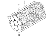
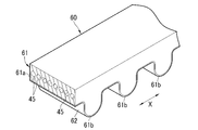
- the multifilament 15 has a plurality of composite materials 10 and a matrix resin 16.
- a multifilament 15 composed of six composite materials 10 is drawn, but the number of composite materials 10 is not particularly limited, and for example, the multifilament 15 is composed of thousands to hundreds of thousands. You can also do it. Further, a plurality of composite materials 10 can be twisted together to form one multifilament 15.
- the matrix resin 16 for example, a resin such as polyurethane or an elastomer such as synthetic rubber can be used.
- the matrix resin 16 is interposed between the composite materials 10 to bond the composite materials 10 to each other. This matrix resin is impregnated into the structure 12 of each composite material 10 and cured.
- the fiber 11 is not particularly limited, and examples thereof include resin fibers such as nylon, polyester, vinylon, and acrylic, glass fibers, and mineral fibers.
- the diameter of the fiber 11 is also not particularly limited, and those having a diameter in the range of 5 ⁇ m or more and 100 ⁇ m or less can be preferably used, and those having a diameter in the range of 5 ⁇ m or more and 30 ⁇ m or less can be more preferably used.
- a long fiber 11 is used, and the length thereof is preferably 50 m or more, more preferably 100 m or more and 100,000 m or less, and further preferably 100 m or more and 10000 m or less.
- the fibers 11 may be cut short after the structure 12 is formed.
- the CNTs 14 constituting the structure 12 are evenly dispersed and entangled on almost the entire surface of the fibers 11 to form a network structure in which a plurality of CNTs 14 are connected to each other in an entangled state.
- the connection here includes a physical connection (mere contact) and a chemical connection.
- the CNTs 14 are in direct contact with each other without the presence of a dispersant such as a surfactant or an inclusion such as an adhesive between them.
- some CNTs 14 constituting the structure 12 are directly attached and fixed to the surface of the fiber 11.
- the structure 12 is directly attached to the surface of the fiber 11.
- the fact that the CNT 14 directly adheres to the surface of the fiber 11 means that the CNT 14 directly adheres to the fiber 11 without any dispersant such as a surfactant or an adhesive intervening between the CNT 14 and the surface. Yes, the adhesion (fixation) is due to the bond by Van der Waals force. Since some of the CNTs 14 constituting the structure 12 are directly attached to the surface of the fiber 11, the structure 12 comes into direct contact with the surface of the fiber 11 without the intervention of a dispersant or an adhesive. It is in contact.
- the CNT14 As the CNT14, a bent shape is used. As a result, some CNTs 14 constituting the structure 12 are fixed to the fibers 11 by being entangled with other CNTs 14 without directly contacting the surface of the fibers 11. Further, there are some that are directly attached to the surface of the fiber 11 and are fixed to the fiber 11 by being entangled with other CNTs 14. Hereinafter, the fixation of the CNT 14 to the fiber 11 will be collectively referred to as attachment to the fiber 11.
- the state in which the CNT 14 is entangled or entangled includes a state in which a part of the CNT 14 is pressed against another CNT 14.
- the CNT 14 constituting the structure 12 is fixed to the fiber 11 by being entangled with another CNT 14 although it is not in direct contact with the surface of the fiber 11 in addition to directly adhering to the surface of the fiber 11 as described above.
- the structure 12 of this example is composed of more CNTs 14 than the CNTs directly attached to the surface of the fiber as in the conventional composite material structure. That is, the number of CNTs 14 attached to the fibers 11 is larger than that of the conventional one, and the thickness of the structure 12 is also larger than that of the conventional one.
- the composite material 10 exhibits the performance of electrical conductivity and thermal conductivity derived from CNTs. To do. Further, since the CNT 14 is attached to the surface of the fiber 11 without any inclusions, the CNT 14 constituting the structure 12 is difficult to be peeled off from the surface of the fiber 11, and the composite material 10 and the secondary product containing the composite material 10 are the same. Mechanical strength is improved. Moreover, since the structure 12 has a large thickness, the above-mentioned mechanical strength is further improved. Therefore, even if the fiber 11 has a large diameter, the composite material 10 and the secondary product having improved mechanical strength can be obtained. In the following, the case of the fiber-reinforced molded product as the secondary product will be described, but the same applies to the case of the resin-impregnated fiber and the multifilament.
- a fiber bundle composed of a plurality of composite materials 10 on which a structure 12 is formed is impregnated with a matrix resin and cured. Since the matrix resin of the fiber-reinforced molded product is impregnated into the structure 12 and cured, the structure 12 of each composite material 10 is fixed to the matrix resin together with the surface of the fiber 11. As a result, each fiber 11 is firmly adhered to the matrix resin, and the peel strength between the composite material 10 and the matrix resin is improved. Further, since the adhesion with the matrix resin extends over the entire composite material 10, the effect of fiber reinforcement can be obtained in the entire fiber reinforced molded product.
- each fiber 11 in the fiber reinforced molded body there is a region (hereinafter referred to as a composite region) formed by impregnating the CNT 14 constituting the structure 12 with the matrix resin and curing it as described above. Since the structure 12 has CNTs 14 floating from its surface, the concentration (density) of CNTs 14 in the composite region decreases as the distance from the composite material 10 increases. In such a composite region, the CNT 14 and the matrix resin are composited to have high strength and flexibility derived from the CNT 14. Further, such a composite region provides an effect of relaxing stress concentration, a restraining effect of suppressing displacement of the composite material 10, an effect of efficiently absorbing mechanical energy from the outside, and the like.
- the vibration damping characteristic (vibration damping property) of the fiber-reinforced molded product is improved.
- the fibers 11 inside the fiber-reinforced molded product are displaced.
- the displacement of the fiber 11 causes the structure 12 in the composite region to stretch, and the network structure of the CNT 14 provides a restraining effect.
- the characteristics of CNT 14 are exhibited and the elastic modulus of the fiber-reinforced molded product is increased.
- the characteristics derived from CNT14 of the fiber-reinforced molded product are exhibited by the properties of the composite region as described above, the effect of the composite region, and the like.
- the structure 12 has a structure in which the number of CNTs 14 attached to the fibers 11 is increased and the CNTs 14 are woven like fibers of a non-woven fabric, so that a composite structure such as the structure 12 is not formed.
- the properties derived from the CNT of the fiber-reinforced molded body are high.
- the structures 12 formed in the plurality of composite materials 10 are independent of each other, and the structure 12 of one composite material 10 and the structure 12 of the other composite material 10 do not share the same CNT 14. .. That is, the CNT 14 included in the structure 12 provided on one fiber 11 is not included in the structure 12 provided on the other fiber 11.
- a sizing agent (not shown) is fixed to the surface of the CNT 14 constituting the structure 12.
- This sizing agent comprises a cured or uncured product of a reaction-curable resin, a thermosetting resin, or a thermoplastic resin.
- the sizing agent is formed by subjecting it to a sizing treatment.
- the sizing agent covers the surface of the CNTs 14, and at the contacting portion where the CNTs 14 are in contact with each other, an inclusion portion that wraps and covers the contacting portion is formed.
- This inclusion portion makes the state in which the CNTs 14 are in contact with each other stronger, and makes the structure 12 more difficult to collapse.
- the sizing agent is fixed to each CNT 14 in a state where it does not enter between the CNTs 14 that are in contact with each other, so that the CNTs 14 at the contact portion are in direct contact with each other.
- a plurality of CNTs 14 form a gap (mesh) surrounding the gap, but the sizing agent fills the gap so as not to prevent the structure 12 from being impregnated with the matrix resin. It is preferable not to block it.
- the volume of the sizing agent is preferably 30% or less with respect to the volume of CNT 14 of the structure 12.
- the sizing agent is formed on the surface of the CNT 14, and is different from the fixing resin portion described later, which enters the inside of the structure 12 and fixes the CNT 14 to the fiber 11. Further, it is not necessary to apply a sizing agent to the structure 12.
- the CNT 14 attached to the fiber 11 has a bent shape.
- the curved shape of the CNT 14 is due to having a bent portion (bent portion) due to the presence of a five-membered ring and a seven-membered ring in the graphite structure of the CNT 14, and the CNT 14 is curved as observed by SEM. It is a shape that can be evaluated as being bent.
- the curved shape of the CNT 14 means that there are at least one bent portion per the average length of the range of use described later of the CNT 14.
- the curved CNT 14 adheres to the surface of the curved fiber 11 in various postures even if it is long.
- the bent CNT 14 a space (gap) is likely to be formed between the surface of the fiber 11 to which the CNT 14 is attached and between the CNTs 14 to which the CNT 14 is attached, and another CNT 14 enters the space. Therefore, by using the bent CNTs 14, the number of CNTs 14 attached to the fibers 11 (the number of CNTs 14 forming the structure 12) is larger than that in the case of using the CNTs having a high linearity.
- the length of the CNT 14 is preferably in the range of 0.1 ⁇ m or more and 10 ⁇ m or less. If the length of the CNT 14 is 0.1 ⁇ m or more, the CNTs 14 can be entangled with each other to form a structure 12 in direct contact or direct connection, and as described above, the other CNTs 14 can form a structure 12. It is possible to form a space to enter more reliably. Further, when the length of the CNT 14 is 10 ⁇ m or less, the CNT 14 does not adhere across the fibers 11. That is, as described above, the CNT 14 contained in the structure 12 provided in one fiber 11 is not included in the structure 12 provided in the other fiber 11.
- the length of the CNT 14 is more preferably in the range of 0.2 ⁇ m or more and 5 ⁇ m or less. If the length of the CNT 14 is 0.2 ⁇ m or more, the number of CNTs 14 attached can be increased to make the structure 12 thicker, and if the length is 5 ⁇ m or less, the CNTs 14 aggregate when the CNTs 14 are attached to the fibers 11. It is difficult and easier to disperse evenly. As a result, the CNT 14 adheres to the fiber 11 more uniformly.
- CNTs having high linearity are mixed as CNTs adhering to the fiber 11 and that CNTs outside the above-mentioned length range are mixed. Even if there is a mixture, for example, the number of CNTs attached to the fibers 11 can be increased by allowing the CNTs having high linearity to enter the space formed by the CNTs 14.
- the average diameter of CNT14 is preferably in the range of 1 nm or more and 15 nm or less, and more preferably in the range of 3 nm or more and 10 nm or less. If the diameter of the CNT 14 is 15 nm or less, the CNT 14 is highly flexible, easily adheres along the surface of the fiber 11, is easily entangled with other CNTs 14 and fixed to the fiber 11, and further forms the structure 12. It will be more reliable. Further, if it is 10 nm or less, the bond between the CNTs 14 constituting the structure 12 becomes strong.
- the diameter of the CNT 14 is a value measured using a transmission electron microscope (TEM) photograph.
- the CNT 14 may be single-layer or multi-layer, but is preferably multi-layer.
- the number of CNTs 14 attached to the fibers 11 can be increased and the thickness of the structure 12 can be increased as compared with the case where the CNTs having high linearity are used.
- the structure 12 is formed in which the CNT 14 is woven like a fiber of a non-woven fabric.
- One of the improved mechanical strengths of secondary products is the improvement of durability against repeated bending.
- the effect of improving the peel strength due to the presence of the structure 12 and the effect of absorbing mechanical energy by the composite region Therefore, it is considered that the durability against repeated bending is enhanced.
- This improvement in peel strength and the effect of absorbing mechanical energy are further enhanced as the number of CNTs 14 adhering to the surface of the fiber 11 is increased, so that the durability against repeated bending becomes higher.
- the composite material 10 having such characteristics is suitable as a spring material such as a coil spring or a leaf spring to which a load is repeatedly applied, and a secondary product containing the composite material 10 is applied to various springs such as a coil spring or a leaf spring. be able to.
- a secondary product using the composite material 10 for example, a fiber-reinforced molded product
- the composite regions impregnated with the matrix resin in the structure 12 and cured are fixed to each other to form a crosslinked structure in which the fibers 11 are crosslinked. ..
- the composite region in which the impregnated matrix resin is cured has a higher hardness than the cured matrix resin alone and has a large elastic limit, that is, high elasticity.
- the composite region has higher wear resistance than the matrix resin.
- the crosslinked structure is formed when the distances between the composite materials 10 are close to each other so that the structures 12 come into contact with each other, the larger the thickness of the structure 12, the more advantageous it is in increasing the number of crosslinks. .. Further, when the composite material 10 is made into a woven fabric or bundled like a multifilament, the number of crosslinked portions in which the composite regions are fixed to each other increases, and the effect of the crosslinked structure becomes large.
- each part of the structure 12 was, for example, a part of the structure 12 on the surface of the fiber 11 adhered to a cellophane tape or the like and peeled off, and remained on the surface of the fiber 11. It can be obtained by measuring the cross section of the structure 12 with SEM or the like.
- the thickness of the structure 12 is the average of the thicknesses of the structures 12 measured at 10 points in the measurement range so as to cover the measurement range of the predetermined length along the fiber axis direction of the fiber 11 almost evenly. ..
- the length of the measurement range is, for example, five times the upper limit of the length range of the CNT 14 described above.
- the number of CNTs 14 attached to the fibers 11 can be evaluated by the thickness of the structure 12.
- the thickness (average) of the structure 12 obtained as described above is in the range of 10 nm or more and 300 nm or less, preferably in the range of 15 nm or more and 200 nm or less, and more preferably in the range of 50 nm or more and 200 nm or less.
- the thickness of the structure 12 is 200 nm or less, the impregnation property of the resin between the fibers 11 is better.
- the fibers 11 constituting the fiber bundle 20 are substantially aligned with each other in the fiber axial directions without being entangled with each other.
- the fiber axial direction is the axial direction (extended direction) of the fiber 11.
- the fiber bundle 20 is composed of a plurality of fibers 11.
- the number of fibers 11 constituting the fiber bundle 20 is not particularly limited, but may be, for example, in the range of 100 or more and 10 million or less.
- the entanglement of the fibers 11 in the fiber bundle 20 can be evaluated by the degree of disturbance of the fibers 11.
- the fiber bundle 20 is observed at a constant magnification with a scanning electron microscope (SEM), and a predetermined number (for example, 10) is observed in the observed range (range of a predetermined length of the fiber bundle 20).
- SEM scanning electron microscope
- the length of the fiber 11 of the above is measured.
- the degree of disturbance of the fibers 11 can be evaluated based on the variation in length of the predetermined number of fibers 11 obtained from this measurement result, the difference between the maximum value and the minimum value, and the standard deviation.
- the fibers 11 are not substantially entangled by measuring the degree of entanglement according to the method for measuring the degree of entanglement in, for example, JIS L1013: 2010 "Chemical fiber filament yarn test method".
- JIS L1013: 2010 “Chemical fiber filament yarn test method”. The smaller the measured degree of entanglement, the less the fibers 11 are entangled with each other in the fiber bundle 20.
- the fiber bundle 20 in which the fibers 11 are not substantially entangled with each other or is less entangled with each other can easily open the fibers 11 uniformly.
- the CNT 14 can be easily adhered uniformly to each fiber 11, and the fiber bundle 20 is uniformly impregnated with the resin, and each of the composite materials 10 contributes to the strength.
- the fiber bundle 20 is placed in a CNT isolated dispersion (hereinafter, simply referred to as a dispersion) in which the CNT 14 is isolated and dispersed. Immerse and impart mechanical energy to the dispersion.
- Isolation and dispersion refers to a state in which CNTs 14 are physically separated one by one and dispersed in a dispersion medium without being entangled, and the proportion of aggregates in which two or more CNTs 14 are aggregated in a bundle is 10%. Refers to the following states.
- the proportion of the aggregate is 10% or more, the aggregation of CNT 14 in the dispersion medium is promoted, and the adhesion of CNT 14 to the fiber 11 is inhibited.
- the attachment device 21 includes a CNT attachment tank 22, guide rollers 23 to 26, an ultrasonic generator 27, a traveling mechanism (not shown) for traveling the fiber bundle 20 at a constant speed, and the like. Will be done.
- the dispersion liquid 28 is housed in the CNT attachment tank 22.
- the ultrasonic generator 27 irradiates the dispersion liquid 28 in the CNT adhering tank 22 with ultrasonic waves from the lower side of the CNT adhering tank 22.
- the attachment device 21 is continuously supplied with a long fiber bundle 20 (for example, about 100 m) in which the structure 12 is not formed.
- the supplied fiber bundle 20 is wound around the guide rollers 23 to 26 in order, and travels at a constant speed by the traveling mechanism.
- the fiber bundle 20 to which the sizing agent is not attached to each fiber 11 is supplied to the bonding device 21.
- the sizing agent referred to here is attached to the surface of the fiber 11 in order to prevent entanglement of the fiber 11, and is different from the sizing agent and the fixing resin portion described above.
- the fiber bundle 20 is wound around the guide rollers 23 to 26 in an opened state.
- the fiber bundle 20 wound around the guide rollers 23 to 26 is less likely to be entangled with the fibers 11 due to the action of an appropriate tension.
- the winding angle of the fiber bundle 20 around the guide rollers 24 to 26 is preferably smaller (90 ° or less).
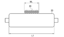
- the guide rollers 23 to 26 are all flat rollers. As shown in FIG. 5, the roller length (length in the axial direction) L1 of the guide roller 23 is sufficiently larger than the width WL of the spread fiber bundle 20.
- the guide rollers 24 to 26 are the same as the guide rollers 23, and their roller lengths are sufficiently larger than the width WL of the spread fiber bundle 20. For example, the guide rollers 23 to 26 are all the same size.
- a plurality of fibers 11 are lined up in the thickness direction (diameter direction of the guide roller).
- the guide rollers 24 and 25 of the guide rollers 23 to 26 are arranged in the CNT attachment tank 22. As a result, between the guide rollers 24 and 25, the fiber bundle 20 runs linearly in the dispersion liquid 28 at a constant depth.
- the traveling speed of the fiber bundle 20 is preferably in the range of 0.5 m / min or more and 10000 m / min or less.
- the traveling speed of the fiber bundle 20 is 100 m / min or less, the entanglement of the fibers 11 can be suppressed more effectively and the uniformity of adhesion of the CNT 14 can be further improved.
- it is more preferable that the traveling speed of the fiber bundle 20 is within the range of 5 m / min or more and 50 m / min or less.
- the ultrasonic generator 27 applies ultrasonic vibration as mechanical energy to the dispersion liquid 28. This creates a reversible reaction state in which the dispersed state in which the CNTs 14 are dispersed and the aggregated state in which the CNTs 14 are aggregated alternately change in the dispersion liquid 28.
- the CNT 14 adheres to each fiber 11 by van der Waals force when shifting from the dispersed state to the agglutinated state.
- the mass of the fiber 11 with respect to the CNT 14 is as large as 100,000 times or more, and the energy for the attached CNT 14 to be detached is larger than the energy due to the ultrasonic vibration.
- the CNT 14 once attached to the fiber 11 is not peeled off from the fiber 11 even by the ultrasonic vibration after the attachment. Since the masses of the CNTs 14 are extremely small, they alternate between a dispersed state and an aggregated state due to ultrasonic vibration.
- the frequency of ultrasonic vibration applied to the dispersion liquid 28 is preferably 40 kHz or more and 950 kHz or less.
- the frequency is 40 kHz or more, the entanglement of the fibers 11 in the fiber bundle 20 is suppressed. Further, when the frequency is 950 kHz or less, the CNT 14 adheres well to the fiber 11.
- the frequency of ultrasonic vibration is preferably 100 kHz or higher, more preferably 130 kHz or higher. Further, the frequency of ultrasonic vibration is more preferably 430 kHz or less.
- the number of CNTs 14 adhering to the fibers 11 is almost maximized while ensuring the uniformity of adhesion of the CNTs 14 to the fibers 11 by shifting the CNTs 14 from the dispersed state to the agglomerated state 65,000 times.
- the maximum value of the number of adhered particles changes depending on the CNT concentration of the dispersion liquid 28, and increases as the CNT concentration of the dispersion liquid 28 increases. However, if the CNT concentration of the dispersion liquid 28 becomes so high that the CNT 17 cannot take a dispersed state when ultrasonic vibration is applied, the CNT 17 cannot be attached to the fiber 11.
- the length of the period during which the fiber bundle 20 is traveling in the dispersion liquid 28, that is, the time during which the fiber bundle 20 is traveling between the guide rollers 24 and 25 (hereinafter referred to as the immersion time) is applied to the dispersion liquid 28.
- the traveling speed of the fiber bundle 20 may be 12 m / min or less. Further, even when the fiber bundle 20 is immersed in the dispersion liquid 28 in a plurality of times, the number of adhered CNTs 14 can be substantially maximized if the total immersion time is 65,000 times or more of the period of ultrasonic vibration.
- a standing wave having a fixed sound pressure (amplitude) distribution is generated in the dispersion liquid 28 in the CNT adhesion tank 22 by the ultrasonic vibration applied from the ultrasonic generator 27. ..
- the guide rollers 24 and 25 are oriented in the depth direction so that the fiber bundle 20 travels in the dispersion liquid 28 at a depth at which the standing wave node of ultrasonic vibration, that is, the sound pressure is minimized.
- the position has been adjusted. Therefore, the depth from the liquid surface of the dispersion liquid 28 in which the fiber bundle 20 travels in the dispersion liquid 28 is D, and the wavelengths of the standing waves of the ultrasonic vibration generated in the dispersion liquid 28 are ⁇ and n.
- the wavelength ⁇ of the standing wave can be obtained based on the speed of sound in the dispersion liquid 28 and the frequency of ultrasonic vibration applied from the ultrasonic generator 27.
- the depth of the fiber bundle 20 running in the dispersion liquid 28 it is possible to suppress the vibration of the fiber 11 due to the sound pressure and prevent the thread disorder due to the thread slack, and the fibers 11 can be prevented from being disturbed.
- the fiber 11 is less likely to be stretched in the fiber axis direction due to the sound pressure of the standing wave, and the plastic deformation of the fiber 11 in the fiber axis direction can be prevented.
- the depth at which the fiber bundle 20 travels in the dispersion liquid 28 may deviate slightly from the node of the standing wave.
- n ⁇ ⁇ / 2- ⁇ / 8 or more n ⁇ ⁇ / 2 + ⁇ / 8 It is preferably within the following range (n ⁇ ⁇ / 2- ⁇ / 8 ⁇ D ⁇ n ⁇ ⁇ / 2 + ⁇ / 8).
- the fiber bundle 20 is drawn out of the dispersion liquid 28 and then dried.
- the sizing agent is applied to the structure 12 by sequentially performing the sizing treatment and the drying on the dried fiber bundle 20.
- the sizing process can be performed by a general method.
- the sizing agent is not particularly limited, and various reaction-curable resins, thermosetting resins, and thermoplastic resins can be used as described above.
- the thermosetting resin include epoxy resin, phenol resin, melamine resin, urea resin (urea resin), unsaturated polyester, alkyd resin, thermosetting polyimide, and resin having a reactive group.
- the thermoplastic resin include polyethylene, polypropylene, polystyrene, acrylonitrile / styrene (AS) resin, acrylonitrile / butadiene / styrene (ABS) resin, methacrylic resin (PMMA, etc.), general-purpose resin such as vinyl chloride, polyamide, polyacetal, and the like.
- Examples thereof include engineering plastics such as polyethylene terephthalate, ultrahigh molecular weight polyethylene and polycarbonate, and super engineering plastics such as polyphenylene sulfide, polyether ether ketone, liquid crystal polymer, polytetrafluoroethylene, polyetherimide, polyarylate and polyimide.
- a resin serving as a sizing agent it is preferable to use a solution in which a resin serving as a sizing agent is dissolved, and it is preferable to apply the solution to the fiber bundle 20 or the like to attach the sizing agent to the CNT 14 of the structure 12.
- the dispersion liquid 28 used for adhering the CNTs 14 to the composite material 10 is prepared by adding, for example, a long CNT (hereinafter referred to as a material CNT) to the dispersion medium and using a homogenizer, a shearing force, an ultrasonic disperser, or the like to obtain the material CNTs. Is cut to obtain CNT14 having a desired length, and the CNT14 is prepared by making the dispersion uniform.
- a material CNT hereinafter referred to as a material CNT
- the dispersion medium examples include alcohols such as water, ethanol, methanol and isopropyl alcohol, and organic substances such as toluene, acetone, tetrahydrofuran (THF), methyl ethyl ketone (MEK), hexane, normal hexane, ethyl ether, xylene, methyl acetate and ethyl acetate.
- alcohols such as water, ethanol, methanol and isopropyl alcohol
- organic substances such as toluene, acetone, tetrahydrofuran (THF), methyl ethyl ketone (MEK), hexane, normal hexane, ethyl ether, xylene, methyl acetate and ethyl acetate.
- THF tetrahydrofuran
- MEK methyl ethyl ketone
- hexane normal hexane
- the material CNT that is the source of the curved CNT 14 is a curved CNT.
- material CNTs those having the same diameter of individual material CNTs are preferable.
- An example of the material CNT is shown in the SEM photograph of FIG.
- the material CNTs are preferably those capable of isolating and dispersing CNTs even if the length of each CNT produced by cutting is large. As a result, a dispersion liquid 28 in which CNT 14 satisfying the above-mentioned length conditions is isolated and dispersed can be easily obtained.
- the composite material 10 of this example as described above, a bent shape is attached as the CNT 14, so that the composite material 10 is formed between the CNT 14 and the surface of the fiber 11 to which the CNT 14 is attached, between the attached CNTs 14, and the like. Another CNT 14 enters the space. As a result, more CNT 14 adheres to the fiber 11. Further, since the CNT 14 is firmly adhered to the fiber 11 to form the structure 12, the CNT 14 is more difficult to peel off from the fiber 11.
- the fiber-reinforced molded product produced by using such a composite material 10 has higher CNT-derived characteristics.
- the secondary product produced by using the composite material 10 as described above has mechanical properties such as vibration damping characteristics (vibration damping property) and elastic modulus change characteristics as compared with the conventional secondary products using the composite material. improves. Regarding the change characteristic of the elastic modulus, the increase in the elastic modulus of the fiber-reinforced molded product is suppressed with respect to the increase in the collision speed with the fiber-reinforced molded product.
- the concentration of CNT14 in the dispersion liquid 28 is preferably in the range of 0.003 wt% or more and 3 wt% or less.
- the concentration of CNT 14 in the dispersion liquid 28 is more preferably 0.005 wt% or more and 0.5 wt% or less.
- the fixing of CNTs to the surface of the fibers is due to the binding of the fibers and CNTs by van der Waals force, but in addition to this, the binding portion that reinforces the fixing of CNTs to the surface of the fibers. May be provided.
- the binding portion is, for example, an epoxy resin cured in a state of being inserted into a gap formed between each surface (peripheral surface) of the fiber and the CNT directly attached (contacted) to the fiber.
- the epoxy resin is a fiber bundle containing fibers in which a structure is formed by dissolving it in a solvent such as toluene, xylene, acetone, methyl ethyl ketone, methyl isobutyl ketone (MIBK), butanol, ethyl acetate or butyl acetate to form a solution. After soaking, heat. As a result, the uncured epoxy resin is allowed to enter the gaps formed between the fibers and the surfaces of the CNTs and cured.
- a solvent such as toluene, xylene, acetone, methyl ethyl ketone, methyl isobutyl ketone (MIBK), butanol, ethyl acetate or butyl acetate.
- a solution of epoxy resin which is the material of the binding portion, may be emulsified and used.
- it can be emulsified by adding an emulsifier such as a nonionic emulsifier to a solution in which an epoxy resin is dissolved in a solvent.
- the binding portion may be, for example, a phenol resin, a polyurethane resin, a melamine resin, a urea resin, a polyimide resin, or the like, in addition to the epoxy resin.
- a silane coupling agent or an inorganic adhesive can also be used as the binding portion.
- the composite material of the second embodiment has a plurality of fixing resin portions for partially fixing a part of the plurality of CNTs constituting the structure to the surface of the fiber. Since the composite material of the second embodiment is the same as the composite material of the first embodiment except that a fixing resin portion is provided instead of the sizing agent, substantially the same members are designated by the same reference numerals. Therefore, the detailed description thereof will be omitted.
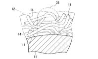
- the composite material 10A is provided with a plurality of fixing resin portions 38 for partially fixing a part of the plurality of CNTs 14 constituting the structure 12 to the surface of the fiber 11.
- the composite material 10A may be a resin-impregnated fiber, or may be used as a single yarn constituting a multifilament or a reinforcing fiber of a fiber-reinforced molded product.
- the fixed resin portion 38 is obtained by curing the resin into particles that reach the surface of the fiber 11 from the surface of the structure 12.
- the fixing resin portion 38 is fixed to the surface of the fiber 11 to which the bottom portion is attached, and is also fixed to the CNT 14 of the structure 12 covered by the portion above the bottom portion. In this way, the fixing resin portion 38 fixes the CNT 14 to the fiber 11 by fixing to both the surface of the fiber 11 and a part of the CNT 14.
- the fixing resin portion 38 partially fixes a part of the plurality of CNTs 14 constituting the structure 12 to the surface of the fiber 11, and is provided so as to be scattered on the surface of the fiber 11. , The CNT 14 of the structure 12 is fixed at each location. The upper portion of the fixed resin portions 38 provided scattered in this way is exposed on the surface of the structure 12, and the fixed resin portions 38 are also scattered and observed on the surface of the structure 12.
- the fixed resin portion 38 is formed in a range extending from the surface of the structure 12 to the surface of the fiber 11 in the radial direction of the fiber 11 (the thickness direction of the structure 12), and the fiber 11 is formed. It is fixed to the surface of the CNT 14 and is fixed to the portion of the CNT 14 contained therein.
- the CNT 14 of the structure 12 may have a portion attached to the surface of the fiber 11, a portion overlapping the other CNT 14 or a portion sandwiched therein, which is fixed to the fixing resin portion 38. Further, in some CNTs 14, the end portion and the central portion thereof are fixed to the fixing resin portion 38. In this way, the CNT 14 fixed to the fixing resin portion 38 is strongly fixed to the fiber 11 by the fixing resin portion 38.
- the portion of the CNT 14 that is not covered with the fixed resin portion 38 adheres to the surface of the fiber 11 by van der Waals force as described above, and therefore has a weaker force than the portion fixed by the fixed resin portion 38. By action, it floats away from the surface of the fiber 11 and can move on the surface of the fiber 11. Further, on the surface of the structure 12, the portion not fixed by the fixing resin portion 38 of the CNT 14 is in a free state in which the portion is separated from the surface of the structure 12 and can be lifted.
- the partial dropout of the structure 12 is suppressed as compared with the case where the CNT 14 of the structure 12 is not fixed by the fixing resin portion 38.
- the characteristics derived from the CNT of the fiber-reinforced molded product are further enhanced. Since the CNT 14 of the fixed resin portion 38 is constrained to the surface of the fiber 11, the current from the fiber 11 can be easily passed, which can contribute to the improvement of the conductivity of the fiber reinforced molded product.
- the CNTs 14 constituting the structure 12 may be fixed to the fibers 11 by the fixing resin portion 38, it is sufficient if some of the CNTs 14 are fixed. That is, at least a part of the CNT 14 constituting the structure 12 may be fixed by the fixing resin portion 38. Since the CNT 14 forms a film as a structure 12 having a non-woven fabric-like structure, the performance can be exhibited as long as at least a part of the CNT 14 constituting the structure 12 is fixed.
- the number ratio N of the fixed resin portion 38 which is the number per 5 ⁇ m square on the surface (outer peripheral surface) of the structure 12 in a plan view, is preferably in the range of 27 or more and 130 or less. Further, on the surface of the structure 12 viewed in a plan view, the area ratio S of the fixed resin portion 38 is preferably in the range of 6% or more and 45% or less, and the area ratio S is in the range of 7% or more and 30% or less. More preferably.
- the area ratio S is the ratio of the area where the plurality of fixed resin portions 38 cover the surface of the structure 12 to the surface area of the structure 12 on the surface of the structure 12 in a plan view, and is the ratio of the area of the structure 12 in a predetermined range.
- S1 is the area where each fixed resin portion 38 within a predetermined range covers the surface of the structure 12.
- the peripheral surface of the structure 12 is observed in a plane from a direction orthogonal to the fiber axis direction of the fiber 11.
- the surface of the structure 12 can be regarded as the surface of the fiber 11, and the fixed resin portion 38 is a structure for each fixed resin portion 38.
- the area covering the surface of the body 12 and the area covering the surface of the fiber 11 can be regarded as substantially the same. Therefore, the number ratio N and the area ratio S are the number ratio, which is the number of fixed resin portions 38 per 5 ⁇ m square on the surface (outer peripheral surface) of the fiber 11 in a plan view, and the fiber 11 on the surface of the fiber 11 in a plan view. It can be regarded as the ratio of the area where the fixed resin portion 38 covers the surface of the fiber 11 to the surface area.
- the structure 12 formed on the peripheral surface of the fiber 11 is observed in a plane using an SEM photograph. Then, a 5 ⁇ m square observation frame is set on the flat observation image of the structure 12 in the SEM photograph, the number of the fixed resin portions 38 in the observation frame is counted, and the number is defined as the number ratio N. Similarly, the area of each fixed resin portion 38 observed in the observation frame is obtained, and the area ratio S is calculated by assuming that the total area of each of these fixed resin portions 38 is the area S1 and the area of the observation frame is the surface area S2. be able to.
- the observation frame G is preferably set so that its center of gravity coincides with the radial center of the fiber 11.
- the CNT 14 can be reliably fixed to the surface of the fiber 11, and the partial shedding of the structure 12 can be reduced. Further, when the number ratio N and the area ratio S are reduced, the portion of the CNT 14 that is not fixed by the fixed resin portion 38 increases, and the degree of freedom of the CNT 14 and the degree of freedom of the structure 12 are increased.
- the CNT 14 can be reliably fixed to the fiber 11 by the fixing resin portion 38, and the effect of reducing partial dropout of the structure 12 is certain.
- the properties derived from CNT of the fiber-reinforced molded product are further enhanced.
- the number ratio N is 130 or less or the area ratio S is 45% or less, the CNT 14 which is entirely covered with the fixed resin portion 38 can be sufficiently reduced.
- the number ratio N and the area ratio S are preferably within the above ranges at the same time.
- the area ratio S can be increased or decreased substantially in proportion to the number ratio N, and the number ratio N and the area ratio S can simultaneously satisfy the above conditions.
- the total area of the fixing resin 38 of 5 ⁇ m in square in the surface, seen in plan view, of the structure 12 it will be in the range of 1.5 ⁇ m 2 ⁇ 11.25 ⁇ m 2.
- the substantial area of one per fixing resin portion 38 on the surface of the structure 12 it is preferable that the 0.03 .mu.m 2 or 1.12 .mu.m 2 within the following ranges.
- the individual area of the fixing resin portion 38 is 0.03 ⁇ m 2 or more, a fixing force for securely fixing the CNT 14 to the surface of the fiber 11 can be obtained. In this case as well, the effect of reducing the partial dropout of the structure 12 can be surely obtained.
- the individual area of the fixed resin portion 38 is 1.12 ⁇ m 2 or less, a sufficient degree of freedom of the CNT 14 can be obtained.
- the area ratio S and the number ratio N of the fixed resin portion 38 in a plan view and the individual substantial area of the fixed resin portion 38 can be obtained by using image analysis software (for example, Winroof2015 (manufactured by Mitani Corporation)). Can be done.
- image analysis software for example, Winroof2015 (manufactured by Mitani Corporation)
- the fiber-reinforced molded product or the like produced from the composite material 10A including the structure 12 composed of the curved CNT 14 is derived from the CNT 14 and has improved characteristics as compared with the conventional one.
- the elastic modulus of the fiber-reinforced molded product using the composite material 10A is enhanced by the restraining effect of suppressing the displacement of the fiber 11 due to the composite region. Further, in the fiber-reinforced molded product, the increase in the elastic modulus of the fiber-reinforced molded product is suppressed with respect to the increase in the collision speed with the fiber-reinforced molded product due to the restraining effect of the composite region between the fibers. As a result, the velocity dependence of the elastic modulus becomes small. Furthermore, the fixing resin portion 38 can further increase the growth resistance of delamination cracks.
- the manufacturing process of the composite material 10A is the same as that of the first embodiment except that the fixing resin portion 38 is formed instead of the sizing treatment for adhering the sizing agent to the surface of the structure 12. .. That is, the fixing resin portion 38 is formed by applying the fixing resin to the fiber bundle 20 that has been drawn out from the dispersion liquid 28 (see FIG. 2) and then dried.
- the fixing resin applying treatment can be a treatment according to the material to be the fixing resin portion 38 and its form.
- the fixing resin applying treatment there is a method of using an emulsion type treatment liquid in which an uncured resin (polymer) to be a fixing resin portion 38 is dispersed in droplet form as a dispersion medium.
- an emulsion type treatment liquid in which an uncured resin (polymer) to be a fixing resin portion 38 is dispersed in droplet form as a dispersion medium.
- the fiber bundle 20 in which the structure 12 is formed on each fiber 11 is opened and brought into contact with the treatment liquid to attach the resin to the fiber bundle 20, and the dispersion medium is evaporated after the adhesion treatment.
- the curing treatment of curing the resin to form the fixed resin portion 38 is sequentially performed.
- a resin having a curable property that is, a curable resin
- the curable resin may be any of a thermosetting resin, a reaction curable resin and the like.
- the cured resin obtained by curing the curable resin may be a thermoplastic resin. Specific examples thereof include epoxy resin, urethane resin, urea resin, polyimide resin, vinyl acetate, acrylic resin, olefin resin, vinyl chloride, phenol resin, melamine resin, rubber-based resin, silicon-based resin and inorganic adhesive. However, it is not limited to these.
- the fixed resin portion 38 preferably has a high affinity with the matrix resin. Therefore, it is preferable that the fixed resin portion 38 and the matrix resin are, for example, a combination of polar resins or a combination of non-polar resins.
- dispersion medium of the treatment liquid examples include water, ethanol, acetone, MEK, N, N-dimethylformamide, N, N-dimethylacetamide, N-methylpyrrolidone, toluene and xylene. These dispersion media may be used alone or in combination of two or more. As the dispersion medium, water is preferable from the viewpoint of handleability and safety.
- concentration of the resin in the treatment liquid after dilution is appropriately adjusted so as to be the amount of adhesion of the target fixed resin portion 38 (ratio of the mass of the fixed resin portion 38 to the composite material 10A (wt%)).
- the amount of the fixed resin portion 38 adhered to the surface of the fiber 11 after the drying treatment is preferably in the range of 0.1 wt% or more and 5.0 wt% or less, more preferably in the range of 0.3 wt% or more and 3.0 wt% or less. Is.
- the particle size of the resin in the treatment liquid is preferably in the range of 0.05 ⁇ m or more and 1 ⁇ m or less, and more preferably in the range of 0.1 ⁇ m or more and 0.4 ⁇ m or less.
- the particle size of the resin in the treatment liquid can be determined by a laser analysis method. If the particle size of the resin in the treatment liquid is 0.05 ⁇ m or more, the CNT 14 can be reliably fixed to the surface of the fiber 11, and if it is 1 ⁇ m or less, the resin can be reliably fixed between the CNTs 14 constituting the structure 12. It can enter and can surely prevent the CNT 14 from being covered with the resin. Further, if it is 0.1 ⁇ m or more, the resin size is sufficient for fixing the non-woven fabric-like structure 12, and if it is 0.4 ⁇ m or less, the structure 12 can be partially fixed.
- the particle diameter using an emulsion type of processing liquid containing 0.4 ⁇ m or less in the range of resins than 0.1 [mu] m fixed resin portion 38 within each area of 0.03 .mu.m 2 or 1.12 .mu.m 2 or less Can be formed.
- the number ratio N is set to be within the range of 27 or more and 130 or less. can do.
- the method of adhesion treatment using the treatment liquid is not particularly limited, and examples thereof include a roller immersion method, a roller contact method, and a spray method.
- the curing treatment method is not particularly limited, and for example, hot air, a hot plate, a heating roller, various infrared heaters, and the like can be used.
- FIG. 10 shows a flat belt 40 as an example of a product using the composite material 10.
- the flat belt 40 is used as, for example, a power transmission belt or the like.
- the flat belt 40 has a structure in which a reinforcing cloth 42 and a surface rubber layer 43 are laminated on both sides of the internal rubber layer 41, respectively, and a cord core wire 45 is embedded in the internal rubber layer 41.
- the inner rubber layer 41 is made of, for example, nitrile rubber, carboxylated nitrile rubber, hydrogenated nitrile rubber, chloroprene rubber, chlorosulphonized polyethylene, polybutadiene rubber, natural rubber, EPM, EPDM, urethane rubber, acrylic rubber and the like. ..
- the reinforcing cloth 42 is provided to improve the durability of the flat belt 40, and for example, woven or knitted cloth such as polyester fiber, nylon fiber, aramid fiber, glass fiber, carbon fiber, and cotton is used.
- the surface rubber layer 43 is provided to obtain a predetermined frictional force between the flat belt 40 and the conveyed object or power transmission device, and is, for example, a nitrile rubber, a carboxylated nitrile rubber, a hydrogenated nitrile rubber, a chloroprene rubber, or a chlorosulphon. It is made of polyethylene chemical, polybutadiene rubber, natural rubber, EPM, EPDM, urethane rubber, acrylic rubber, silicon rubber and the like.
- the cord core wire 45 As the cord core wire 45, the above-mentioned multifilament 15 in which the composite materials 10 are bonded to each other by the matrix resin 16 impregnated into the structure 12 and cured is used.
- the cord core wire 45 has a fiber axis direction of the multifilament 15 and a longitudinal direction of the flat belt 40 (running direction of the flat belt 40, arrow X direction) coincident with each other. Further, the cord core wires 45 are arranged at a predetermined pitch in the width direction orthogonal to the longitudinal direction of the flat belt 40.
- a twisted multifilament is used as the cord core wire 45, it is preferable to alternately arrange the S-twisted one and the Z-twisted one in order to suppress the skew of the belt.
- the flat belt 40 since the flat belt 40 uses the multifilament made of the composite material 10 as the cord core wire 45, the flat belt 40 has a small elongation with respect to tension and compression, and has high durability against repeated bending.
- a composite material can be used as a cord core wire of various belts, and in particular, the composite material is a toothed belt represented by a timing belt, a V-belt, a V-ribbed belt, or the like. It is suitable as a cord core wire of a transmission belt.
- the example shown in FIG. 11 uses the multifilament 15 as the cord core wire 45 of the V-belt 50
- the example shown in FIG. 12 uses the multifilament 15 as the cord core wire 45 of the timing belt 60. is there.
- the timing belt 60 of FIG. 12 has a rubber layer 61 composed of a belt main body portion 61a and a plurality of tooth portions 61b, and a tooth cloth 62 covering the surface of the rubber layer 61 on the tooth portion 61b side, and the belt main body. It has a structure in which the cord core wire 45 is embedded in the portion 61a.
- FIG. 13 shows the results of evaluating the interfacial adhesive strength between the glass fiber and the matrix resin depending on the presence or absence of CNT adhesion.
- a plurality of test pieces A in which CNT composite fibers using glass fibers as fibers 11 are embedded in a soft epoxy resin and a plurality of test pieces B in which glass fibers (raw yarn) are embedded in a soft epoxy resin are prepared. Then, it was evaluated by the fragmentation method.
- the glass fiber (raw thread) is passed through the dispersion liquid 28 irradiated with ultrasonic waves by the same procedure as described above, and the CNT 14 is sufficiently and uniformly adhered to the glass fiber, and the surface thereof is adhered to the glass fiber.
- the fiber 11 having the structure 12 formed therein was used. No sizing agent or binding part was added.
- the test piece A was produced by taking out one glass fiber having a structure 12 formed on its surface and embedding the glass fiber in a soft epoxy resin.
- the diameter of the glass fiber (raw yarn) was about 16 ⁇ m.
- FIG. 14 shows an SEM photograph of the structure 12 formed on the surface of the glass fiber used for the test piece A.
- the test piece B was prepared by burying one glass fiber (raw thread) to which CNT was not attached in a soft epoxy resin.
- the preparation conditions for the test piece B were the same as those for the test piece A, except that the CNTs did not adhere to the glass fibers.
- a tensile load is applied until the glass fibers are no longer cut, and then the length of each cut piece of the glass fiber at a constant length in the test piece is measured for each test piece. Then, for each test piece, the average length of the cut pieces (cut fiber length) was calculated.
- the cut fiber lengths of the test pieces A and B measured by the fragmentation method as described above are shown in FIG.
- the cut fiber length of the test piece A that is, the one in which the CNT 14 is attached to the glass fiber is shorter than that of the test piece B, that is, the one in which the CNT is not attached to the glass fiber, and the glass fiber and the matrix resin are used.
- the interfacial adhesive strength is high.
- the stress concentration at the interface becomes remarkable because the glass fiber has a diameter of 10 ⁇ m or more, but in the test piece A, the resin elastic modulus at the interface is increased due to the presence of CNT14 on the surface of the glass fiber. It is considered that the interfacial adhesive strength is improved by improving and relaxing the stress concentration.
Landscapes
- Engineering & Computer Science (AREA)
- Chemical & Material Sciences (AREA)
- Textile Engineering (AREA)
- Materials Engineering (AREA)
- Life Sciences & Earth Sciences (AREA)
- Chemical Kinetics & Catalysis (AREA)
- Plasma & Fusion (AREA)
- Organic Chemistry (AREA)
- Physics & Mathematics (AREA)
- General Chemical & Material Sciences (AREA)
- Geochemistry & Mineralogy (AREA)
- Inorganic Chemistry (AREA)
- General Life Sciences & Earth Sciences (AREA)
- Manufacturing & Machinery (AREA)
- Health & Medical Sciences (AREA)
- Medicinal Chemistry (AREA)
- Polymers & Plastics (AREA)
- Reinforced Plastic Materials (AREA)
- Chemical Or Physical Treatment Of Fibers (AREA)
Abstract
Description
[複合素材]
図1において、複合素材10は、繊維11と、この繊維11の表面に形成された構造体12とを含む。構造体12は、複数のカーボンナノチューブ(以下、CNTと称する)14が絡み合ったものである。この複合素材10は、例えば構造体12に樹脂等を含浸させた繊維(以下、樹脂含浸繊維と称する)としたり、マルチフィラメントを構成する単糸や繊維強化成形体の強化繊維に用いられたりする。複合素材10、及びこのような複合素材10を用いて作製される樹脂含浸繊維、マルチフィラメントや繊維強化成形体等(以下、これらを二次製品と称する)は、繊維11の表面に構造体12を有することにより、機械的特性等が向上する。すなわち、繊維11の表面に付着したCNT14に由来して機械的特性等が向上する。 [First Embodiment]
[Composite material]
In FIG. 1, the
次に、複合素材10の製造について説明する。この例では、複数の繊維11からなる繊維束20(図4参照)を用いて複合素材10を製造する場合について説明するが、繊維束20に代えて繊維11単体を用いて、同様に複合素材10を製造することができる。 [Manufacturing method of composite material]
Next, the production of the
複合素材10にCNT14を付着させる際に用いる分散液28は、例えば長尺のCNT(以下、材料CNTと称する)を分散媒に加え、ホモジナイザーや、せん断力、超音波分散機などにより、材料CNTを切断して所望とする長さのCNT14とするとともに、CNT14の分散の均一化を図ることで調製される。 [Dispersion]
The
第2実施形態の複合素材は、構造体を構成する複数のCNTの一部を繊維の表面に部分的に固定する複数の固定樹脂部を有するものである。第2実施形態の複合素材は、サイジング剤に代えて固定樹脂部が設けられている他は、第1実施形態の複合素材と同じであるから、実質的に同じ部材には同一の符号を付して、その詳細な説明を省略する。 [Second Embodiment]
The composite material of the second embodiment has a plurality of fixing resin portions for partially fixing a part of the plurality of CNTs constituting the structure to the surface of the fiber. Since the composite material of the second embodiment is the same as the composite material of the first embodiment except that a fixing resin portion is provided instead of the sizing agent, substantially the same members are designated by the same reference numerals. Therefore, the detailed description thereof will be omitted.
11 繊維
12 構造体
14 カーボンナノチューブ
20 繊維束
38 固定樹脂部
10,
Claims (6)
- 繊維と、
複数のカーボンナノチューブで構成され、前記カーボンナノチューブ同士が直接接触したネットワーク構造を形成するとともに、前記繊維の表面に付着する前記カーボンナノチューブが前記繊維の表面に直接付着した構造体と
を備え、
前記カーボンナノチューブは、屈曲部を有する曲がった形状である
ことを特徴とする複合素材。 With fiber
It is composed of a plurality of carbon nanotubes, forms a network structure in which the carbon nanotubes are in direct contact with each other, and includes a structure in which the carbon nanotubes adhering to the surface of the fiber are directly adhering to the surface of the fiber.
The carbon nanotube is a composite material characterized by having a bent shape having a bent portion. - 前記構造体は、厚さが10nm以上300nm以下の範囲内であることを特徴とする請求項1に記載の複合素材。 The composite material according to claim 1, wherein the structure has a thickness in the range of 10 nm or more and 300 nm or less.
- 前記繊維は、直径が5μm以上100μm以下の範囲内であることを特徴とする請求項1または2に記載の複合素材。 The composite material according to claim 1 or 2, wherein the fiber has a diameter in the range of 5 μm or more and 100 μm or less.
- 屈曲部を有する曲がった形状の複数のカーボンナノチューブが分散された分散液に超音波振動を印加する超音波工程と、
前記超音波振動が印加されている前記分散液に繊維を浸漬し、前記繊維に前記複数のカーボンナノチューブを付着させて、前記繊維の表面に構造体を形成する付着工程と
を有することを特徴とする複合素材の製造方法。 An ultrasonic process in which ultrasonic vibration is applied to a dispersion liquid in which a plurality of curved carbon nanotubes having a bent portion are dispersed, and
The fiber is immersed in the dispersion liquid to which the ultrasonic vibration is applied, and the plurality of carbon nanotubes are attached to the fiber to form a structure on the surface of the fiber. How to manufacture composite materials. - 前記付着工程は、長尺の前記繊維を前記分散液中で走行させ、前記繊維が走行する前記分散液の液面からの深さをD、前記超音波工程によって前記分散液中に生じる前記超音波振動の定在波の波長をλとし、nを1以上の整数としたときに、n・λ/2-λ/8≦D≦n・λ/2+λ/8を満たすことを特徴とする請求項4に記載の複合素材の製造方法。 In the adhesion step, the long fibers are run in the dispersion liquid, the depth of the dispersion liquid on which the fibers run from the liquid surface is D, and the ultra-ultrasonic step is generated in the dispersion liquid by the ultrasonic step. A claim characterized by satisfying n · λ / 2-λ / 8 ≦ D ≦ n · λ / 2 + λ / 8 when the wavelength of the standing wave of ultrasonic vibration is λ and n is an integer of 1 or more. Item 4. The method for producing a composite material according to Item 4.
- 前記超音波工程は、前記超音波振動の周波数が40kHz以上950kHz以下の範囲内であることを特徴とする請求項4または5に記載の複合素材の製造方法。 The method for producing a composite material according to claim 4 or 5, wherein the ultrasonic step has a frequency of the ultrasonic vibration within a range of 40 kHz or more and 950 kHz or less.
Priority Applications (6)
| Application Number | Priority Date | Filing Date | Title |
|---|---|---|---|
| EP20891341.8A EP4063559A4 (en) | 2019-11-20 | 2020-11-20 | Composite material and method for producing same |
| JP2021558473A JPWO2021100859A1 (en) | 2019-11-20 | 2020-11-20 | |
| KR1020227020334A KR20220093248A (en) | 2019-11-20 | 2020-11-20 | Composite material and its manufacturing method |
| US17/778,164 US20230019296A1 (en) | 2019-11-20 | 2020-11-20 | Composite material and method for producing same |
| CN202080079115.8A CN114729499A (en) | 2019-11-20 | 2020-11-20 | Composite material and method for producing same |
| TW109140794A TW202124808A (en) | 2019-11-20 | 2020-11-20 | Composite material and production method for same |
Applications Claiming Priority (4)
| Application Number | Priority Date | Filing Date | Title |
|---|---|---|---|
| JP2019210011 | 2019-11-20 | ||
| JP2019-210011 | 2019-11-20 | ||
| JPPCT/JP2020/042901 | 2020-11-18 | ||
| PCT/JP2020/042901 WO2021100735A1 (en) | 2019-11-20 | 2020-11-18 | Composite material and production method for same |
Publications (1)
| Publication Number | Publication Date |
|---|---|
| WO2021100859A1 true WO2021100859A1 (en) | 2021-05-27 |
Family
ID=75980137
Family Applications (1)
| Application Number | Title | Priority Date | Filing Date |
|---|---|---|---|
| PCT/JP2020/043412 WO2021100859A1 (en) | 2019-11-20 | 2020-11-20 | Composite material and method for producing same |
Country Status (6)
| Country | Link |
|---|---|
| US (1) | US20230019296A1 (en) |
| EP (1) | EP4063559A4 (en) |
| JP (1) | JPWO2021100859A1 (en) |
| KR (1) | KR20220093248A (en) |
| CN (1) | CN114729499A (en) |
| WO (1) | WO2021100859A1 (en) |
Families Citing this family (1)
| Publication number | Priority date | Publication date | Assignee | Title |
|---|---|---|---|---|
| US20200015752A1 (en) * | 2018-07-13 | 2020-01-16 | John R Baxter | Textile utilizing carbon nanotubes |
Citations (3)
| Publication number | Priority date | Publication date | Assignee | Title |
|---|---|---|---|---|
| JP2008201626A (en) * | 2007-02-20 | 2008-09-04 | Toray Ind Inc | Carbon nanotube assembly and its manufacturing method |
| JP2016194165A (en) * | 2015-03-31 | 2016-11-17 | ニッタ株式会社 | Method for producing composite stock and composite stock |
| US20180230634A1 (en) * | 2015-08-08 | 2018-08-16 | Himalibahen K. VYAS | Apparatus for textile processing and method of manufacturing |
Family Cites Families (6)
| Publication number | Priority date | Publication date | Assignee | Title |
|---|---|---|---|---|
| JP2013076198A (en) | 2011-09-13 | 2013-04-25 | Nitta Ind Corp | Cnt/carbon fiber composite material, fiber-reinforced molded article using the composite material and method for producing composite material |
| JP6063562B2 (en) * | 2013-04-24 | 2017-01-18 | ニッタ株式会社 | COMPOSITE MATERIAL, MOLDED ARTICLE AND COMPOSITE MATERIAL MANUFACTURING METHOD |
| JP6489519B2 (en) * | 2014-10-23 | 2019-03-27 | ニッタ株式会社 | Method for producing reinforcing fiber |
| JP6703427B2 (en) * | 2016-03-25 | 2020-06-03 | ニッタ株式会社 | Method for manufacturing composite fabric |
| US20190308905A1 (en) * | 2018-04-09 | 2019-10-10 | Wichita State University | Nanocomposites with interlocking nanostructures |
| KR20210019059A (en) * | 2018-06-11 | 2021-02-19 | 니타 가부시키가이샤 | Composite material, prepreg, carbon fiber reinforced molded body and method of manufacturing composite material |
-
2020
- 2020-11-20 CN CN202080079115.8A patent/CN114729499A/en active Pending
- 2020-11-20 JP JP2021558473A patent/JPWO2021100859A1/ja active Pending
- 2020-11-20 KR KR1020227020334A patent/KR20220093248A/en not_active Application Discontinuation
- 2020-11-20 US US17/778,164 patent/US20230019296A1/en active Pending
- 2020-11-20 WO PCT/JP2020/043412 patent/WO2021100859A1/en unknown
- 2020-11-20 EP EP20891341.8A patent/EP4063559A4/en active Pending
Patent Citations (3)
| Publication number | Priority date | Publication date | Assignee | Title |
|---|---|---|---|---|
| JP2008201626A (en) * | 2007-02-20 | 2008-09-04 | Toray Ind Inc | Carbon nanotube assembly and its manufacturing method |
| JP2016194165A (en) * | 2015-03-31 | 2016-11-17 | ニッタ株式会社 | Method for producing composite stock and composite stock |
| US20180230634A1 (en) * | 2015-08-08 | 2018-08-16 | Himalibahen K. VYAS | Apparatus for textile processing and method of manufacturing |
Non-Patent Citations (1)
| Title |
|---|
| See also references of EP4063559A4 * |
Also Published As
| Publication number | Publication date |
|---|---|
| CN114729499A (en) | 2022-07-08 |
| KR20220093248A (en) | 2022-07-05 |
| EP4063559A4 (en) | 2024-01-24 |
| JPWO2021100859A1 (en) | 2021-05-27 |
| US20230019296A1 (en) | 2023-01-19 |
| EP4063559A1 (en) | 2022-09-28 |
Similar Documents
| Publication | Publication Date | Title |
|---|---|---|
| JP5460333B2 (en) | COMPOSITE LAMINATE HAVING DAMPING INTERMEDIATE AND ITS MANUFACTURING METHOD | |
| CN112567091B (en) | Composite material, prepreg, carbon fiber-reinforced molded body, and method for producing composite material | |
| Habibi et al. | Experimental characterization of short flax fiber mat composites: tensile and flexural properties and damage analysis using acoustic emission | |
| WO2021100859A1 (en) | Composite material and method for producing same | |
| WO2021100735A1 (en) | Composite material and production method for same | |
| WO2004090224A1 (en) | Reinforcing cord for reinforcing rubber and rubber product using the same | |
| WO2022114225A1 (en) | Rotary member and method for manufacturing same | |
| WO2022114217A1 (en) | Composite material, method for producing same, and method for producing reinforcing fiber base material | |
| JP7406959B2 (en) | Composite material, carbon fiber reinforced molded body, and method for producing composite material | |
| JP2003222197A (en) | High load transmission belt | |
| TWI833763B (en) | Composite material, prepreg, carbon fiber reinforced molded article and method of manufacturing composite material | |
| JPH0156297B2 (en) | ||
| JP6547090B1 (en) | Rubber reinforcing cord and rubber product using the same | |
| JP7382460B1 (en) | Injection molded product and method for manufacturing the same, method for manufacturing composite fiber, CNT-adhered carbon fiber and method for manufacturing the same, and method for manufacturing carbon fiber composite material | |
| Tausif et al. | Effect of fibre type on mechanical properties of nonwoven reinforced tpu composites | |
| Murray | Design and development of a new class of intra-filament hybrid composite | |
| JP2004197056A (en) | Roving prepreg package and method for producing the same |
Legal Events
| Date | Code | Title | Description |
|---|---|---|---|
| 121 | Ep: the epo has been informed by wipo that ep was designated in this application |
Ref document number: 20891341 Country of ref document: EP Kind code of ref document: A1 |
|
| ENP | Entry into the national phase |
Ref document number: 2021558473 Country of ref document: JP Kind code of ref document: A |
|
| ENP | Entry into the national phase |
Ref document number: 20227020334 Country of ref document: KR Kind code of ref document: A |
|
| NENP | Non-entry into the national phase |
Ref country code: DE |
|
| ENP | Entry into the national phase |
Ref document number: 2020891341 Country of ref document: EP Effective date: 20220620 |