WO2021100811A1 - 中空糸膜モジュール - Google Patents
中空糸膜モジュール Download PDFInfo
- Publication number
- WO2021100811A1 WO2021100811A1 PCT/JP2020/043214 JP2020043214W WO2021100811A1 WO 2021100811 A1 WO2021100811 A1 WO 2021100811A1 JP 2020043214 W JP2020043214 W JP 2020043214W WO 2021100811 A1 WO2021100811 A1 WO 2021100811A1
- Authority
- WO
- WIPO (PCT)
- Prior art keywords
- hollow fiber
- crimped
- casing
- membrane module
- fiber bundle
- Prior art date
- Legal status (The legal status is an assumption and is not a legal conclusion. Google has not performed a legal analysis and makes no representation as to the accuracy of the status listed.)
- Ceased
Links
Images



Classifications
-
- B—PERFORMING OPERATIONS; TRANSPORTING
- B01—PHYSICAL OR CHEMICAL PROCESSES OR APPARATUS IN GENERAL
- B01D—SEPARATION
- B01D63/00—Apparatus in general for separation processes using semi-permeable membranes
- B01D63/02—Hollow fibre modules
- B01D63/031—Two or more types of hollow fibres within one bundle or within one potting or tube-sheet
-
- B—PERFORMING OPERATIONS; TRANSPORTING
- B01—PHYSICAL OR CHEMICAL PROCESSES OR APPARATUS IN GENERAL
- B01D—SEPARATION
- B01D67/00—Processes specially adapted for manufacturing semi-permeable membranes for separation processes or apparatus
- B01D67/0081—After-treatment of organic or inorganic membranes
- B01D67/0083—Thermal after-treatment
-
- B—PERFORMING OPERATIONS; TRANSPORTING
- B01—PHYSICAL OR CHEMICAL PROCESSES OR APPARATUS IN GENERAL
- B01D—SEPARATION
- B01D67/00—Processes specially adapted for manufacturing semi-permeable membranes for separation processes or apparatus
- B01D67/0081—After-treatment of organic or inorganic membranes
- B01D67/0086—Mechanical after-treatment
-
- B—PERFORMING OPERATIONS; TRANSPORTING
- B01—PHYSICAL OR CHEMICAL PROCESSES OR APPARATUS IN GENERAL
- B01D—SEPARATION
- B01D69/00—Semi-permeable membranes for separation processes or apparatus characterised by their form, structure or properties; Manufacturing processes specially adapted therefor
- B01D69/08—Hollow fibre membranes
- B01D69/084—Undulated fibres
Definitions
- the present invention relates to a hollow fiber membrane module.
- a hollow fiber membrane module using a hollow fiber made of a semipermeable membrane is used in many fields as a device for treating a liquid to be treated flowing through a hollow fiber cavity with a treatment liquid flowing outside the hollow fiber, for example. , It is used as a dialyzer in the medical field and as a water treatment device in the environmental field.
- Examples of such a hollow fiber membrane module include those disclosed in Patent Documents 1 to 3.
- the pressure loss on the treatment liquid side it is important to reduce the pressure difference on the treatment liquid side at the treatment liquid inlet and the treatment liquid outlet of the hollow fiber membrane module, that is, the pressure loss on the treatment liquid side. Further, if the pressure loss on the treatment liquid side is large, the pump that supplies the treatment liquid may be overloaded. However, the current situation is that the technique for reducing the pressure loss on the treatment liquid side is not sufficient.
- the present invention has been made in view of such a situation, and an object of the present invention is to provide a hollow fiber membrane module having a practical processing capacity and a small pressure loss on the processing liquid side.
- a hollow fiber bundle composed of a non-crimped hollow fiber and a crimped hollow fiber is used, and a collecting portion composed of the non-crimped hollow fiber is formed as a hollow fiber.
- a hollow fiber membrane module having a casing and a hollow fiber bundle disposed within the casing.
- the hollow fiber bundle is composed of a crimped hollow fiber and a non-crimped hollow fiber. At least a part of the non-crimped hollow fiber forms an assembly part.
- a hollow fiber membrane module is provided.
- the present invention provides a hollow fiber membrane module having a practical processing capacity and a small pressure loss on the processing liquid side.
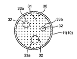
- FIG. 5 is a schematic cross-sectional view of a central portion of the casing of the hollow fiber membrane module of FIG. 1, which is substantially perpendicular to the longitudinal direction of the casing.
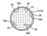
- FIG. 5 is a schematic cross-sectional view of another embodiment of the central portion of the casing of the hollow fiber membrane module of FIG. 1, which is substantially perpendicular to the longitudinal direction of the casing.
- FIG. 5 is a schematic cross-sectional view of yet another embodiment of the central portion of the casing of the hollow fiber membrane module of FIG. 1, which is substantially perpendicular to the longitudinal direction of the casing.
- FIG. 5 is a schematic cross-sectional view of an end portion of the casing of the hollow fiber membrane module of FIG. 5, which is substantially perpendicular to the longitudinal direction of the casing.
- the hollow fiber membrane module 100 has a casing 10 and a hollow fiber bundle 30 arranged in the casing.
- the crimped hollow fiber 31 and the non-crimped hollow fiber 32 are shown by solid lines.
- a part of the end 34 of the hollow fiber bundle 30 is fixed to the end 11 of the casing 10 by the potting material 50.
- the treatment liquid flows into the casing 10 from the treatment liquid inlet 12 provided in the casing 10 (see arrow A), and flows out of the casing 10 from the treatment liquid outlet 13 provided in the casing 10 (see arrow B).
- the liquid to be treated flows into the header 70 from the liquid inlet 71 provided in the header 70 (see arrow C), flows through the cavity of the hollow fiber, and is treated to be provided in the header 70 on the opposite side. It flows out of the header 70 from the liquid outlet 72 (see arrow D).
- the hollow fiber bundle 30 is composed of a large number of hollow fibers (for example, about 5,000 to about 15,000), and is composed of a crimped hollow fiber 31 and a non-crimped hollow fiber 32. As shown in FIG. 1, at least a portion of the non-crimped hollow fiber 32 constituting the hollow fiber bundle, preferably at least 70%, more preferably at least 80%, still more preferably at least 90%, particularly preferably at least 95%. For example, substantially all non-crimped hollow fiber membranes form a gathering portion (hereinafter, may be referred to as “non-crimped hollow fiber gathering portion”) 33. With such a configuration, the pressure loss on the treatment liquid side can be reduced.
- the crimped hollow fiber 31 and the non-crimped hollow fiber 32 are sometimes collectively referred to as a "hollow fiber".
- the "crimped hollow fiber” is a hollow fiber having a crimped portion in the longitudinal direction (that is, the drawing direction) of the hollow fiber, and is, for example, a corrugated wave, a sine wave, a triangular wave, a zigzag, or a spiral. It means a hollow fiber in which shapes such as shapes (for example, amplitude: 0.05 mm or more and 3.00 mm or less, wavelength: 0.5 mm or more and 15 mm or less) or a combination thereof are repeated regularly or irregularly. Further, the crimped hollow fiber may have a twist and / or a swell.
- the crimped hollow fiber may include a non-crimped, that is, a linear or substantially linear (hereinafter, may be referred to as "linear") portion as long as the effect of the present invention is not impaired. ..
- a part of the crimped hollow fiber is non-crimped, for example, when the end of the crimped hollow fiber is non-crimped, the non-crimped portion is rolled. Examples thereof include a mode in which the flow of the treatment liquid in the casing is not substantially affected, such as when the length is up to about 20% of the total length of the reduced hollow fiber.
- the non-crimped hollow fiber means a hollow fiber that is not crimped and is substantially linear.
- the non-crimped hollow fiber may include the above-mentioned crimped portion as long as the effect of the present invention is not impaired.
- the non-crimped hollow fiber is crimped.
- the portion has a length of up to, for example, about 20% of the total length of the non-crimped hollow fiber, there is an embodiment in which the flow of the treatment liquid in the casing is not substantially affected.
- the "aggregate portion" composed of at least a part of the non-crimped hollow fiber means five or more non-crimped hollow fibers in a cross section substantially perpendicular to the longitudinal direction of the casing.
- both of the two non-crimped hollow fibers mean that the crimped hollow fibers are adjacent to each other without being located between them (that is, without the crimped hollow fibers), and between these two yarns.
- Another non-crimped hollow fiber may be present. In other words, at least five non-crimped hollow fibers extend along the longitudinal direction without the intervention of crimped hollow fibers.
- the non-crimped hollow fiber collecting portion 33 is preferably composed of 10 or more, more preferably 20 or more non-crimped hollow fibers. ..
- the non-crimped hollow fiber 32 constituting the hollow fiber collecting portion 33 may have a portion that is in contact with each other and a portion that is not in contact with each other over the entire longitudinal direction thereof. In another aspect, they may be in contact or separated over their entire length.
- the non-crimped hollow fiber collecting portion 33 has a region having less undulations as compared with the crimped hollow fiber 31, so that the flow of the processing liquid becomes smooth and the pressure loss on the processing liquid side It is thought that can be made smaller.
- the above is a mechanism that can be considered at present, and the present invention is not limited by the mechanism. By reducing the pressure loss, for example, the load on the pump that supplies the processing liquid into the hollow fiber membrane module 100 can be reduced.
- the ratio of the number of non-crimped hollow fibers 32 to the total number of crimped hollow fibers 31 and the number of non-crimped hollow fibers 32 is preferably 15% or more, preferably 35% or less. This makes it easier to secure a practical processing capacity and reduce the pressure loss on the processing liquid side.
- the ratio of the number of non-crimped hollow fibers 32 to the total number of crimped hollow fibers 31 and the number of non-crimped hollow fibers 32 is more preferably 17% or more, still more preferably 19% or more, and more. It is preferably 33% or less, more preferably 31% or less.
- the non-crimped hollow fiber collecting portion 33 (33a to 33c) will be described with reference to FIGS. 2 to 4, but the mode of the gathering portion of the non-crimped hollow fiber 32 is not limited thereto.
- 2 to 4 show an intermediate portion between the end portion 11 of the casing 10 and the other end portion 11, for example, a central portion, which is perpendicular to the longitudinal direction of the casing 10 of the hollow fiber membrane module 100 of FIG. It is a schematic sectional view of.
- the non-crimped hollow fiber collecting portion 33a may be a collection of non-crimped hollow fiber 32 in a cylindrical shape having a circular or elliptical cross-sectional shape.
- the non-crimped hollow fiber collecting portion 33b is a layered non-crimped hollow fiber 32 extending from the outer peripheral portion of the hollow fiber bundle 30 toward the inside thereof. May be a set of.
- the non-crimped hollow fiber collecting portion 33c is in a layered manner extending from the outer peripheral portion of the hollow fiber bundle 30 to the other outer peripheral portion through the inside thereof.
- the non-crimped hollow fibers 32 may be assembled.
- FIGS. 2 to 4 the center of the opening that defines a part of the hollow fibers of a large number of hollow fibers is indicated by a point, and the non-crimped hollow fiber collecting portion 33 is virtually defined. Shape is shown by a solid line.
- the illustrated points are exemplary, and the number of points illustrated in the assembly 33 does not correspond to the number of hollow fibers that make up the assembly.
- This virtual shape is a figure that integrally surrounds the non-crimped hollow fiber of the collecting portion 33 of the non-crimped hollow fiber in a cross section substantially perpendicular to the longitudinal direction of the casing, and has the minimum peripheral length. Means that has. Since the diameter of the hollow fiber is very small compared to the inner diameter of the casing, it may be considered that the opening of the hollow fiber is substantially a point in the cross section. Therefore, when, for example, the openings of the five hollow fibers forming the gathering portion are located so as to correspond to the vertices of the pentagon, the shape of the gathering portion may be considered to be substantially a pentagon.
- the hollow fiber bundle 30 may include a plurality of non-crimped hollow fiber collecting portions 33. This means that a plurality of non-crimped hollow fiber collecting portions 33 appear in a cross section substantially perpendicular to the longitudinal direction of the casing.
- the above-mentioned shape of the gathering portion may be any suitable shape.
- a sea-island structure that is, non-rolling corresponding to an island
- a plurality of cylindrical non-crimped hollow fiber collecting portions 33a having a circular or elliptical cross-sectional shape are distributed in the hollow fiber bundle 30.
- the structure in which the gathering portion 33a of the crimped hollow fiber is located in the crimped hollow fiber corresponding to the sea) may be used.
- a layered non-crimped hollow fiber collecting portion 33b extending from the outer peripheral portion of the hollow fiber bundle 30 toward the inside thereof and a cylinder having a circular or elliptical cross section.
- the structure may be such that a plurality of non-crimped hollow fiber collecting portions 33a are distributed in the hollow fiber bundle 30.
- a cylindrical non-crimped hollow fiber collecting portion 33a having a circular or elliptical cross section may be located on the outer peripheral portion of the hollow fiber bundle 30.
- a layered non-crimped hollow fiber collecting portion 33b extending from the outer peripheral portion of the hollow fiber bundle 30 toward the inside thereof and an outer peripheral portion of the hollow fiber bundle 30.
- the layered non-crimped hollow fiber collecting portion 33c extending from the inside to the other outer peripheral portion may have a structure adjacent to each other via the crimped hollow fiber 31.
- a cylindrical non-crimped hollow fiber collecting portion 33a having a circular or elliptical cross-sectional shape is provided. It may be a distributed structure.
- a plurality of non-crimped hollow fiber collecting portions 33 may be further assembled to form an aggregate of the non-crimped hollow fiber collecting portions 33, and the embodiment thereof is not particularly limited.
- the aggregate passes through the interior from, for example, a cylindrical shape having a circular or elliptical cross-sectional shape, a layered portion extending from the outer peripheral portion of the hollow fiber bundle 30 toward the inside, or an outer peripheral portion of the hollow fiber bundle 30. It may have a layered shape extending to the other outer peripheral portion.
- the crimped hollow fiber 31 may be interposed between the non-crimped hollow fiber collecting portions 33.
- the hollow fiber bundle 30 can be prepared, for example, as follows.
- the non-crimped hollow fiber 32 is prepared according to a conventional method
- the crimped hollow fiber 31 is prepared by a method of winding the non-crimped hollow fiber 32 on a bobbin and heat-processing it, a method of passing it between gears, or the like. To do.
- the hollow fiber bundle is cut at a position corresponding to the octagonal apex of the hem and bundled into a cylindrical shape. You may get 30.
- the shape of the star anise is not limited to the octagonal columnar shape, and a polygonal columnar or circular star anise may be used.
- a plurality of semi-bundles obtained by laminating a crimped hollow fiber 31 and a non-crimped hollow fiber 32 in a desired ratio, order, and number are bundled to form a cylindrical hollow fiber bundle. You may get 30.
- a plurality of semi-bundles obtained by mixing the crimped hollow fiber 31 and the non-crimped hollow fiber 32 at a desired ratio may be prepared and bundled in a cylindrical shape to obtain the hollow fiber bundle 30. ..
- the semi-bundle may be composed of, for example, about 500 to about 2,000 hollow fibers.
- the shape defined by the outer circumference of the hollow fiber bundle 30 (this shape is the non-crimped hollow fiber assembly described above).
- the ratio of the total surface area of the shape defined by the outer circumference of the hollow fibers constituting the hollow fiber bundle 30 to the surface area of the portion (that is, the density of the hollow fibers in the hollow fiber bundle 30), hereinafter.
- High fiber density is preferably greater at a portion of the hollow fiber bundle 30 other than the end 34 than at the end 34 of the hollow fiber bundle 30. That is, in the hollow fiber bundle 30, it is preferable that the hollow fibers at the end 34 are relatively sparse as compared with the other portions.
- the treatment liquid inlet 12 and the treatment liquid outlet 13 are usually located at or near the end portion 11 of the casing 10, that is, the hollow fiber bundle 30. It is located at or near the end 34.
- the hollow fiber bundle 30 by making the hollow fiber density of the end 34 smaller than that of the other parts, the portion through which the treatment liquid can flow becomes wider in the vicinity of the end 34 of the hollow fiber bundle 30, so that the treatment liquid can flow from the treatment liquid inlet 12.
- the treatment liquid is poured into the hollow fiber membrane module 100, it is possible to more easily suppress a decrease in the pressure of the treatment liquid in the vicinity of the treatment liquid inlet 12. As a result, the pressure loss on the treatment liquid side can be reduced more easily.
- the hollow fiber density of the portion other than the end portion 34 is higher than that of the end portion 34, the processing capacity of the hollow fiber membrane module can be maintained.
- the hollow fiber is spread in the vicinity of the end 34 of the hollow fiber bundle 30 as compared with the other portions, and the hollow fiber density at the end 34 is the end. It is smaller than the parts other than 34.
- the ratio of the total surface area of the casing 10 (that is, the filling rate of the hollow thread in the casing 10, hereinafter sometimes referred to as “hollow thread filling rate”) is the end 11 of the casing 10 or its vicinity (for example, the filling rate of the hollow thread).
- the treatment liquid inlet 12 and the treatment liquid outlet 13 are usually located in the vicinity of the end portion 11 of the casing 10, that is, the end portion of the hollow fiber bundle 30. It is arranged in the vicinity of 34.
- the hollow fiber filling rate at the end 11 of the casing 10 is set to 55% or less, the portion through which the treatment liquid can flow becomes wider in the vicinity of the end 34 of the hollow fiber bundle 30, so that the treatment liquid is supplied from the treatment liquid inlet 12.
- the hollow fiber membrane module 100 it is possible to more easily suppress a decrease in the pressure of the treatment liquid in the vicinity of the treatment liquid inlet 12. As a result, the pressure loss on the treatment liquid side can be reduced more easily.
- the hollow fiber filling rate at the end 11 of the casing 10 is preferably 32% or more, preferably 53% or less.
- the shape of the casing 10 is not particularly limited, but is usually tubular, particularly cylindrical. While lowering the hollow fiber filling rate at the end 11 of the casing 10, in other parts, the hollow fiber filling rate is increased to increase the hollow fiber density. Therefore, for example, as shown in FIG. 1, the end 11 A casing 10 having a structure in which is wider than the other parts may be used, and a hollow fiber bundle 30 in which the end portion 34 is wider than the other parts may be used.
- a casing 10 having the above-mentioned shape is used, and a hollow fiber bundle 30 whose end 34 is wider than the other parts is used. This makes it easier to increase the density of the hollow fibers filled in the portions other than the end 11 while reducing the hollow fiber filling rate at the end 11 of the casing 10.
- the mode of filling the hollow fiber in the end portion 11 of the casing 10 is not particularly limited, and the end portion 11 of the casing 10 may be uniformly filled, or as described in detail below, the end portion 11 of the casing 10
- the predetermined portion of the above may be filled so as to form a gap between, for example, the cylindrical casing 10 and the hollow fiber bundle 30.
- the gap 35 provided between the end 11 of the casing 10 and the outer circumference 30'of the hollow fiber bundle 30 facilitates the flow of dialysate in the vicinity of the end 11 of the casing 10 and facilitates pressure loss. It can be suppressed.
- the outer circumference of the hollow fiber bundle 30 is shown by a virtual line 30'in FIG.
- the casing 10 may have a baffle plate 14 between the treatment liquid inlet 12 and the hollow fiber bundle, and between the treatment liquid outlet 13 and the hollow fiber bundle 30.
- the treatment liquid introduced from the treatment liquid inlet 12 can be more uniformly distributed in the casing 10.
- the material constituting the hollow yarn is not particularly limited, and for example, cellulose acetate, cellulose triacetate, polyacrylonitrile, polysulfone, polyvinyl alcohol, polyacrylate, polymethacrylate, polymethylmethacrylate, polyethersulfone, polysulfone, polyamide, polyester, polyethylene. , Polypropylene and the like. Particularly, polyether sulfone or cellulose triacetate is preferable.
- the shape of the header 70 is not particularly limited, and may be appropriately selected according to the shape of the end portion 11 of the casing 10.
- the material constituting the casing 10 and the header 70 is not particularly limited, and may be made of resin, for example.
- the resin is not particularly limited, and for example, polypropylene, polycarbonate, polystyrene, polyethylene, polytetrafluoroethylene, polyester, polyvinyl chloride, or ABS (acrylonitrile-butadiene-). It may be styrene) or the like.
- the material constituting the potting material 50 is not particularly limited, and may be, for example, a polyurethane resin, an epoxy resin, a silicone resin, or the like.
- the method for manufacturing the hollow fiber membrane module 100 according to the embodiment of the present invention is not particularly limited except for the step of preparing the hollow fiber bundle 30, and a generally known method may be used.
- the hollow fiber membrane module 100 according to the embodiment of the present invention can be preferably used as a dialyzer for treating blood (treatment liquid) with a dialysate (treatment liquid) in the medical field, for example, and has a practical clearance (treatment). Capacity) can be maintained and the pressure loss on the dialysate side can be reduced.
- the hollow fiber membrane module 100 according to the embodiment of the present invention as a dialyzer, the pressure loss on the dialysate side can be reduced, so that a pump generally used in the dialysate process can be used for priming and the like. Hemodialysis can be started promptly without taking a relatively long time.
- the non-crimped hollow fiber 32 was prepared according to a conventional method, and the crimped hollow fiber 31 was prepared by passing the non-crimped hollow fiber 32 between the gears.
- a plurality of small bundles 1 in which a plurality of crimped hollow fibers 31 (outer diameter: 280 ⁇ m) are bundled, and a plurality of small bundles 2 in which a plurality of non-crimped hollow fibers 32 (outer diameter: 280 ⁇ m) are bundled are prepared.
- a plurality of semi-bundles obtained by bundling a plurality of small bundles 1 and a plurality of small bundles 2 were prepared, and they were bundled in a cylindrical shape to obtain a hollow fiber bundle 30.
- the total number of crimped hollow fibers 31 and non-crimped hollow fibers 32 constituting the hollow fiber bundle 30 was 11,520, of which 20% (about 2300) were non-crimped hollow fibers.
- a hollow fiber bundle 30 made of polyether sulfone is inserted into a cylindrical casing 10 made of polypropylene, and a part of both ends 34 of the hollow fiber bundle 30 is made into both ends 11 of the casing 10 by a potting material 50 made of urethane resin.
- the header 50 was attached to manufacture the hollow fiber membrane module 100 (dialyzer) of the embodiment as shown in FIG.
- the cross section of the intermediate portion of the hollow fiber membrane module 100 which is perpendicular to the longitudinal direction of the hollow fiber membrane module 100 of the embodiment, was confirmed, it was found to be circular or elliptical in the manner shown in FIGS.
- a plurality of cylindrical non-crimped yarn collecting portions 33a having an outer shape were distributed inside and the outer peripheral portion of the hollow fiber bundle 30.
- the inner circumference inner diameter: 4.
- the area of the surface defined by (92 cm) was 19.01 cm 2
- the hollow fiber filling rate at the end 11 was 37.3%.
- the hollow fiber density is larger in the portion other than the end portion 34 than in the end portion 34 of the hollow fiber bundle 30, and the end portion 34 of the hollow fiber bundle 30 is other than that. It was wider than the part.
- Comparative example A conventional hollow fiber membrane module 100 (dialyzer) of a comparative example was manufactured in the same manner as in the examples except that the crimped hollow fiber 31 was used instead of the non-crimped hollow fiber 32.
- the pressure loss and clearance on the dialysate side were measured using the test circuit of FIG. 4 of JIS T3250: 2013.
- the blood flow rate was 200 mL / min and the dialysate flow rate was 500 mL / min.
- the pressure loss on the dialysate side was 3.8 kPa.
- the pressure loss on the dialysate side is smaller as 3.0 kPa, and the pressure loss on the dialysate side is 20% as compared with the conventional hollow fiber membrane module 100 of the comparative example. It was possible to reduce the above. Further, the hollow fiber membrane module 100 of the example had a practical clearance equivalent to that of the conventional hollow fiber membrane module 100 of the comparative example. That is, the hollow fiber membrane module 100 of the embodiment was able to further reduce the pressure loss on the dialysate side while having a practical clearance.
Landscapes
- Chemical & Material Sciences (AREA)
- Chemical Kinetics & Catalysis (AREA)
- Inorganic Chemistry (AREA)
- Engineering & Computer Science (AREA)
- Manufacturing & Machinery (AREA)
- Physics & Mathematics (AREA)
- Thermal Sciences (AREA)
- Separation Using Semi-Permeable Membranes (AREA)
Priority Applications (2)
| Application Number | Priority Date | Filing Date | Title |
|---|---|---|---|
| JP2021558444A JPWO2021100811A1 (https=) | 2019-11-20 | 2020-11-19 | |
| EP20891334.3A EP4063004A4 (en) | 2019-11-20 | 2020-11-19 | HOLLOW FIBER MEMBRANE MODULE |
Applications Claiming Priority (2)
| Application Number | Priority Date | Filing Date | Title |
|---|---|---|---|
| JP2019209763 | 2019-11-20 | ||
| JP2019-209763 | 2019-11-20 |
Publications (1)
| Publication Number | Publication Date |
|---|---|
| WO2021100811A1 true WO2021100811A1 (ja) | 2021-05-27 |
Family
ID=75980128
Family Applications (1)
| Application Number | Title | Priority Date | Filing Date |
|---|---|---|---|
| PCT/JP2020/043214 Ceased WO2021100811A1 (ja) | 2019-11-20 | 2020-11-19 | 中空糸膜モジュール |
Country Status (3)
| Country | Link |
|---|---|
| EP (1) | EP4063004A4 (https=) |
| JP (1) | JPWO2021100811A1 (https=) |
| WO (1) | WO2021100811A1 (https=) |
Cited By (1)
| Publication number | Priority date | Publication date | Assignee | Title |
|---|---|---|---|---|
| JP2025523129A (ja) * | 2022-08-04 | 2025-07-17 | コーロン インダストリーズ インク | 燃料電池用加湿器のカートリッジ及び燃料電池用加湿器 |
Citations (8)
| Publication number | Priority date | Publication date | Assignee | Title |
|---|---|---|---|---|
| JPS523819B2 (https=) | 1974-10-26 | 1977-01-31 | ||
| JPS57194007A (en) | 1981-05-26 | 1982-11-29 | Nitsushiyoo:Kk | Hollow yarn type permeating device |
| JPS6422308A (en) | 1987-07-20 | 1989-01-25 | Organo Kk | Hollow yarn module using crimped hollow yarn |
| JP2003079721A (ja) | 2001-09-11 | 2003-03-18 | Toyobo Co Ltd | 血液透析用モジュール |
| WO2004094047A1 (ja) * | 2003-04-23 | 2004-11-04 | Asahi Medical Co., Ltd. | 中空糸膜型流体処理器 |
| JP2010046587A (ja) * | 2008-08-20 | 2010-03-04 | Toyobo Co Ltd | 中空糸膜モジュール |
| JP2016528948A (ja) | 2013-06-20 | 2016-09-23 | ガンブロ・ルンディア・エービーGambro Lundia Ab | 毛細管透析装置 |
| EP3427814A1 (en) * | 2014-02-06 | 2019-01-16 | Gambro Lundia AB | Hemodialyzer for blood purification |
Family Cites Families (3)
| Publication number | Priority date | Publication date | Assignee | Title |
|---|---|---|---|---|
| IN149938B (https=) * | 1977-11-30 | 1982-06-12 | Monsanto Co | |
| DE10007327A1 (de) * | 2000-02-17 | 2001-08-30 | Fresenius Medical Care De Gmbh | Filtervorrichtung, vorzugsweise Hohlfaserdialysator mit gelockten Hohlfasern |
| EP3388139A1 (en) * | 2017-04-13 | 2018-10-17 | Gambro Lundia AB | Optimized hemodialyzer for blood purification |
-
2020
- 2020-11-19 EP EP20891334.3A patent/EP4063004A4/en not_active Withdrawn
- 2020-11-19 JP JP2021558444A patent/JPWO2021100811A1/ja active Pending
- 2020-11-19 WO PCT/JP2020/043214 patent/WO2021100811A1/ja not_active Ceased
Patent Citations (8)
| Publication number | Priority date | Publication date | Assignee | Title |
|---|---|---|---|---|
| JPS523819B2 (https=) | 1974-10-26 | 1977-01-31 | ||
| JPS57194007A (en) | 1981-05-26 | 1982-11-29 | Nitsushiyoo:Kk | Hollow yarn type permeating device |
| JPS6422308A (en) | 1987-07-20 | 1989-01-25 | Organo Kk | Hollow yarn module using crimped hollow yarn |
| JP2003079721A (ja) | 2001-09-11 | 2003-03-18 | Toyobo Co Ltd | 血液透析用モジュール |
| WO2004094047A1 (ja) * | 2003-04-23 | 2004-11-04 | Asahi Medical Co., Ltd. | 中空糸膜型流体処理器 |
| JP2010046587A (ja) * | 2008-08-20 | 2010-03-04 | Toyobo Co Ltd | 中空糸膜モジュール |
| JP2016528948A (ja) | 2013-06-20 | 2016-09-23 | ガンブロ・ルンディア・エービーGambro Lundia Ab | 毛細管透析装置 |
| EP3427814A1 (en) * | 2014-02-06 | 2019-01-16 | Gambro Lundia AB | Hemodialyzer for blood purification |
Non-Patent Citations (1)
| Title |
|---|
| See also references of EP4063004A4 |
Cited By (1)
| Publication number | Priority date | Publication date | Assignee | Title |
|---|---|---|---|---|
| JP2025523129A (ja) * | 2022-08-04 | 2025-07-17 | コーロン インダストリーズ インク | 燃料電池用加湿器のカートリッジ及び燃料電池用加湿器 |
Also Published As
| Publication number | Publication date |
|---|---|
| EP4063004A1 (en) | 2022-09-28 |
| JPWO2021100811A1 (https=) | 2021-05-27 |
| EP4063004A4 (en) | 2023-11-15 |
Similar Documents
| Publication | Publication Date | Title |
|---|---|---|
| EP2701763B1 (en) | Combination oxygenator and arterial filter device for treating blood in an extracorporeal blood circuit | |
| EP2701762B1 (en) | Combination oxygenator and arterial filter device with a fiber bundle of continuously wound hollow fibers for treating blood in an extracorporeal blood circuit | |
| EP0089122B1 (en) | Hollow fibre oxygenator, assembly containing same and method for making same | |
| US5240610A (en) | Flexible tubular filtering material | |
| KR101684204B1 (ko) | 중공사막 방사 노즐 | |
| CN100421771C (zh) | 空心纤维膜型流体处理装置 | |
| KR930012046B1 (ko) | 선택적 투과성 중공 섬유단 및 이를 포함하는 유체 분리기 | |
| US6004511A (en) | Hollow fiber oxygenator | |
| JP2000516852A (ja) | 中空の、多次元列の薄膜 | |
| EP0895786A1 (en) | Oxygenator of hollow fiber membrane type | |
| JP2000189762A (ja) | フィルタデバイス | |
| WO2021100811A1 (ja) | 中空糸膜モジュール | |
| JPH05123541A (ja) | 液体膜モジユール | |
| JP2008155009A (ja) | 中空糸膜型血液浄化用モジュールおよびその製造方法 | |
| JP3878675B2 (ja) | 中空ファイバー酸素付加装置 | |
| JP2017074567A (ja) | 逆浸透水処理方法 | |
| JPWO2016111320A1 (ja) | 濾過器、体腔液処理システム及び体腔液処理方法 | |
| EP0848987B1 (de) | Hohlfasermodul | |
| JP2000042099A (ja) | 中空糸膜型血液透析器 | |
| JPS6315381B2 (https=) | ||
| JP7647062B2 (ja) | フィルタ装置の製造方法及びフィルタ装置 | |
| JP2009078121A (ja) | 血液浄化器及びその製造方法 | |
| KR20240007190A (ko) | 개선된 분리 특성을 갖는 중공사막 필터 | |
| JPH0984873A (ja) | 中空糸膜型透析濾過器 | |
| JPS6311972Y2 (https=) |
Legal Events
| Date | Code | Title | Description |
|---|---|---|---|
| 121 | Ep: the epo has been informed by wipo that ep was designated in this application |
Ref document number: 20891334 Country of ref document: EP Kind code of ref document: A1 |
|
| ENP | Entry into the national phase |
Ref document number: 2021558444 Country of ref document: JP Kind code of ref document: A |
|
| NENP | Non-entry into the national phase |
Ref country code: DE |
|
| ENP | Entry into the national phase |
Ref document number: 2020891334 Country of ref document: EP Effective date: 20220620 |