WO2021100784A1 - Heat generation device, heat utilization system and film-like heat generation element - Google Patents
Heat generation device, heat utilization system and film-like heat generation element Download PDFInfo
- Publication number
- WO2021100784A1 WO2021100784A1 PCT/JP2020/043076 JP2020043076W WO2021100784A1 WO 2021100784 A1 WO2021100784 A1 WO 2021100784A1 JP 2020043076 W JP2020043076 W JP 2020043076W WO 2021100784 A1 WO2021100784 A1 WO 2021100784A1
- Authority
- WO
- WIPO (PCT)
- Prior art keywords
- layer
- heating element
- fluid
- film
- heat
- Prior art date
Links
- 230000020169 heat generation Effects 0.000 title abstract description 16
- 239000012530 fluid Substances 0.000 claims abstract description 185
- UFHFLCQGNIYNRP-UHFFFAOYSA-N Hydrogen Chemical compound [H][H] UFHFLCQGNIYNRP-UHFFFAOYSA-N 0.000 claims abstract description 128
- NJPPVKZQTLUDBO-UHFFFAOYSA-N novaluron Chemical compound C1=C(Cl)C(OC(F)(F)C(OC(F)(F)F)F)=CC=C1NC(=O)NC(=O)C1=C(F)C=CC=C1F NJPPVKZQTLUDBO-UHFFFAOYSA-N 0.000 claims abstract description 127
- 229910052739 hydrogen Inorganic materials 0.000 claims abstract description 126
- 239000001257 hydrogen Substances 0.000 claims abstract description 126
- 239000007789 gas Substances 0.000 claims abstract description 72
- 238000003860 storage Methods 0.000 claims abstract description 72
- 229910052751 metal Inorganic materials 0.000 claims abstract description 42
- 239000002184 metal Substances 0.000 claims abstract description 42
- 238000010438 heat treatment Methods 0.000 claims description 349
- 229910045601 alloy Inorganic materials 0.000 claims description 54
- 239000000956 alloy Substances 0.000 claims description 54
- 238000001816 cooling Methods 0.000 claims description 48
- 229910052759 nickel Inorganic materials 0.000 claims description 25
- 229910052802 copper Inorganic materials 0.000 claims description 21
- 229910052749 magnesium Inorganic materials 0.000 claims description 20
- 229910052804 chromium Inorganic materials 0.000 claims description 19
- 229910052742 iron Inorganic materials 0.000 claims description 19
- 239000000919 ceramic Substances 0.000 claims description 16
- 229910052763 palladium Inorganic materials 0.000 claims description 16
- 229910052748 manganese Inorganic materials 0.000 claims description 8
- 239000004020 conductor Substances 0.000 claims description 7
- 238000010521 absorption reaction Methods 0.000 abstract description 8
- 238000003795 desorption Methods 0.000 abstract 1
- XLYOFNOQVPJJNP-UHFFFAOYSA-N water Substances O XLYOFNOQVPJJNP-UHFFFAOYSA-N 0.000 description 116
- 238000004544 sputter deposition Methods 0.000 description 76
- 238000004519 manufacturing process Methods 0.000 description 35
- 239000000126 substance Substances 0.000 description 29
- PXHVJJICTQNCMI-UHFFFAOYSA-N Nickel Chemical compound [Ni] PXHVJJICTQNCMI-UHFFFAOYSA-N 0.000 description 24
- 238000000034 method Methods 0.000 description 23
- 239000013077 target material Substances 0.000 description 22
- 239000010949 copper Substances 0.000 description 19
- 238000000992 sputter etching Methods 0.000 description 19
- 239000000463 material Substances 0.000 description 15
- CURLTUGMZLYLDI-UHFFFAOYSA-N Carbon dioxide Chemical compound O=C=O CURLTUGMZLYLDI-UHFFFAOYSA-N 0.000 description 14
- 238000006243 chemical reaction Methods 0.000 description 10
- 238000005530 etching Methods 0.000 description 10
- 239000007788 liquid Substances 0.000 description 10
- 239000012466 permeate Substances 0.000 description 10
- 238000012545 processing Methods 0.000 description 10
- 230000015572 biosynthetic process Effects 0.000 description 9
- 238000009826 distribution Methods 0.000 description 9
- 230000000740 bleeding effect Effects 0.000 description 8
- 238000010248 power generation Methods 0.000 description 8
- 229910002092 carbon dioxide Inorganic materials 0.000 description 7
- 239000001569 carbon dioxide Substances 0.000 description 7
- 238000011084 recovery Methods 0.000 description 7
- 125000004435 hydrogen atom Chemical group [H]* 0.000 description 6
- 238000011068 loading method Methods 0.000 description 6
- 238000002161 passivation Methods 0.000 description 6
- 229910019589 Cr—Fe Inorganic materials 0.000 description 5
- 238000002485 combustion reaction Methods 0.000 description 5
- QGZKDVFQNNGYKY-UHFFFAOYSA-N Ammonia Chemical compound N QGZKDVFQNNGYKY-UHFFFAOYSA-N 0.000 description 4
- XKRFYHLGVUSROY-UHFFFAOYSA-N Argon Chemical compound [Ar] XKRFYHLGVUSROY-UHFFFAOYSA-N 0.000 description 4
- IJGRMHOSHXDMSA-UHFFFAOYSA-N Atomic nitrogen Chemical compound N#N IJGRMHOSHXDMSA-UHFFFAOYSA-N 0.000 description 4
- YZCKVEUIGOORGS-OUBTZVSYSA-N Deuterium Chemical compound [2H] YZCKVEUIGOORGS-OUBTZVSYSA-N 0.000 description 4
- 239000000654 additive Substances 0.000 description 4
- 230000000996 additive effect Effects 0.000 description 4
- 239000003463 adsorbent Substances 0.000 description 4
- 229910052805 deuterium Inorganic materials 0.000 description 4
- 230000005611 electricity Effects 0.000 description 4
- XMBWDFGMSWQBCA-UHFFFAOYSA-N hydrogen iodide Chemical compound I XMBWDFGMSWQBCA-UHFFFAOYSA-N 0.000 description 4
- 230000002093 peripheral effect Effects 0.000 description 4
- 238000009751 slip forming Methods 0.000 description 4
- 238000004804 winding Methods 0.000 description 4
- XZXYQEHISUMZAT-UHFFFAOYSA-N 2-[(2-hydroxy-5-methylphenyl)methyl]-4-methylphenol Chemical compound CC1=CC=C(O)C(CC=2C(=CC=C(C)C=2)O)=C1 XZXYQEHISUMZAT-UHFFFAOYSA-N 0.000 description 3
- 229910000975 Carbon steel Inorganic materials 0.000 description 3
- 229910000831 Steel Inorganic materials 0.000 description 3
- 229940107816 ammonium iodide Drugs 0.000 description 3
- 229910000963 austenitic stainless steel Inorganic materials 0.000 description 3
- 239000010962 carbon steel Substances 0.000 description 3
- 238000007872 degassing Methods 0.000 description 3
- 238000001514 detection method Methods 0.000 description 3
- 230000004992 fission Effects 0.000 description 3
- 239000000446 fuel Substances 0.000 description 3
- 230000006870 function Effects 0.000 description 3
- 239000005431 greenhouse gas Substances 0.000 description 3
- 229910000043 hydrogen iodide Inorganic materials 0.000 description 3
- 229910044991 metal oxide Inorganic materials 0.000 description 3
- 150000004706 metal oxides Chemical class 0.000 description 3
- 239000000203 mixture Substances 0.000 description 3
- 229910021652 non-ferrous alloy Inorganic materials 0.000 description 3
- 238000005192 partition Methods 0.000 description 3
- 239000002994 raw material Substances 0.000 description 3
- 238000001179 sorption measurement Methods 0.000 description 3
- 239000010959 steel Substances 0.000 description 3
- 230000008646 thermal stress Effects 0.000 description 3
- 238000003466 welding Methods 0.000 description 3
- OKTJSMMVPCPJKN-UHFFFAOYSA-N Carbon Chemical compound [C] OKTJSMMVPCPJKN-UHFFFAOYSA-N 0.000 description 2
- 229910021529 ammonia Inorganic materials 0.000 description 2
- 229910052786 argon Inorganic materials 0.000 description 2
- QVGXLLKOCUKJST-UHFFFAOYSA-N atomic oxygen Chemical compound [O] QVGXLLKOCUKJST-UHFFFAOYSA-N 0.000 description 2
- 239000003054 catalyst Substances 0.000 description 2
- 238000005229 chemical vapour deposition Methods 0.000 description 2
- 230000003247 decreasing effect Effects 0.000 description 2
- 238000009792 diffusion process Methods 0.000 description 2
- 238000001035 drying Methods 0.000 description 2
- 238000000605 extraction Methods 0.000 description 2
- -1 for example Substances 0.000 description 2
- 239000001307 helium Substances 0.000 description 2
- 229910052734 helium Inorganic materials 0.000 description 2
- SWQJXJOGLNCZEY-UHFFFAOYSA-N helium atom Chemical compound [He] SWQJXJOGLNCZEY-UHFFFAOYSA-N 0.000 description 2
- 230000006698 induction Effects 0.000 description 2
- 238000001755 magnetron sputter deposition Methods 0.000 description 2
- 238000005259 measurement Methods 0.000 description 2
- 239000012528 membrane Substances 0.000 description 2
- 150000002736 metal compounds Chemical class 0.000 description 2
- VNWKTOKETHGBQD-UHFFFAOYSA-N methane Chemical compound C VNWKTOKETHGBQD-UHFFFAOYSA-N 0.000 description 2
- 239000002086 nanomaterial Substances 0.000 description 2
- 239000001301 oxygen Substances 0.000 description 2
- 229910052760 oxygen Inorganic materials 0.000 description 2
- 239000002245 particle Substances 0.000 description 2
- 238000000926 separation method Methods 0.000 description 2
- 239000007787 solid Substances 0.000 description 2
- 238000000638 solvent extraction Methods 0.000 description 2
- 239000010936 titanium Substances 0.000 description 2
- 229910052719 titanium Inorganic materials 0.000 description 2
- 238000011144 upstream manufacturing Methods 0.000 description 2
- 229910018072 Al 2 O 3 Inorganic materials 0.000 description 1
- 229910004247 CaCu Inorganic materials 0.000 description 1
- VYZAMTAEIAYCRO-UHFFFAOYSA-N Chromium Chemical compound [Cr] VYZAMTAEIAYCRO-UHFFFAOYSA-N 0.000 description 1
- 229910020637 Co-Cu Inorganic materials 0.000 description 1
- RYGMFSIKBFXOCR-UHFFFAOYSA-N Copper Chemical compound [Cu] RYGMFSIKBFXOCR-UHFFFAOYSA-N 0.000 description 1
- 229910005191 Ga 2 O 3 Inorganic materials 0.000 description 1
- 229910017706 MgZn Inorganic materials 0.000 description 1
- ZOKXTWBITQBERF-UHFFFAOYSA-N Molybdenum Chemical compound [Mo] ZOKXTWBITQBERF-UHFFFAOYSA-N 0.000 description 1
- 229910017709 Ni Co Inorganic materials 0.000 description 1
- 229910003267 Ni-Co Inorganic materials 0.000 description 1
- 229910003271 Ni-Fe Inorganic materials 0.000 description 1
- 229910002650 Ni-SiC Inorganic materials 0.000 description 1
- 229910003262 Ni‐Co Inorganic materials 0.000 description 1
- 229910018487 Ni—Cr Inorganic materials 0.000 description 1
- 229910018505 Ni—Mg Inorganic materials 0.000 description 1
- 229910004298 SiO 2 Inorganic materials 0.000 description 1
- NINIDFKCEFEMDL-UHFFFAOYSA-N Sulfur Chemical compound [S] NINIDFKCEFEMDL-UHFFFAOYSA-N 0.000 description 1
- 229910010069 TiCo Inorganic materials 0.000 description 1
- 229910010340 TiFe Inorganic materials 0.000 description 1
- RTAQQCXQSZGOHL-UHFFFAOYSA-N Titanium Chemical compound [Ti] RTAQQCXQSZGOHL-UHFFFAOYSA-N 0.000 description 1
- 229910021536 Zeolite Inorganic materials 0.000 description 1
- 229910008340 ZrNi Inorganic materials 0.000 description 1
- OMOVVBIIQSXZSZ-UHFFFAOYSA-N [6-(4-acetyloxy-5,9a-dimethyl-2,7-dioxo-4,5a,6,9-tetrahydro-3h-pyrano[3,4-b]oxepin-5-yl)-5-formyloxy-3-(furan-3-yl)-3a-methyl-7-methylidene-1a,2,3,4,5,6-hexahydroindeno[1,7a-b]oxiren-4-yl] 2-hydroxy-3-methylpentanoate Chemical compound CC12C(OC(=O)C(O)C(C)CC)C(OC=O)C(C3(C)C(CC(=O)OC4(C)COC(=O)CC43)OC(C)=O)C(=C)C32OC3CC1C=1C=COC=1 OMOVVBIIQSXZSZ-UHFFFAOYSA-N 0.000 description 1
- 230000009471 action Effects 0.000 description 1
- PNEYBMLMFCGWSK-UHFFFAOYSA-N aluminium oxide Inorganic materials [O-2].[O-2].[O-2].[Al+3].[Al+3] PNEYBMLMFCGWSK-UHFFFAOYSA-N 0.000 description 1
- KYKAJFCTULSVSH-UHFFFAOYSA-N chloro(fluoro)methane Chemical compound F[C]Cl KYKAJFCTULSVSH-UHFFFAOYSA-N 0.000 description 1
- 239000010941 cobalt Substances 0.000 description 1
- 229910017052 cobalt Inorganic materials 0.000 description 1
- GUTLYIVDDKVIGB-UHFFFAOYSA-N cobalt atom Chemical compound [Co] GUTLYIVDDKVIGB-UHFFFAOYSA-N 0.000 description 1
- 230000007797 corrosion Effects 0.000 description 1
- 238000005260 corrosion Methods 0.000 description 1
- 238000005520 cutting process Methods 0.000 description 1
- 238000010586 diagram Methods 0.000 description 1
- 229910001873 dinitrogen Inorganic materials 0.000 description 1
- HNPSIPDUKPIQMN-UHFFFAOYSA-N dioxosilane;oxo(oxoalumanyloxy)alumane Chemical compound O=[Si]=O.O=[Al]O[Al]=O HNPSIPDUKPIQMN-UHFFFAOYSA-N 0.000 description 1
- 230000000694 effects Effects 0.000 description 1
- 238000009713 electroplating Methods 0.000 description 1
- 230000007613 environmental effect Effects 0.000 description 1
- 238000010304 firing Methods 0.000 description 1
- 150000002431 hydrogen Chemical class 0.000 description 1
- OCVXZQOKBHXGRU-UHFFFAOYSA-N iodine(1+) Chemical compound [I+] OCVXZQOKBHXGRU-UHFFFAOYSA-N 0.000 description 1
- 229910001338 liquidmetal Inorganic materials 0.000 description 1
- 230000007246 mechanism Effects 0.000 description 1
- 150000002739 metals Chemical class 0.000 description 1
- 229910052750 molybdenum Inorganic materials 0.000 description 1
- 239000011733 molybdenum Substances 0.000 description 1
- 229910052758 niobium Inorganic materials 0.000 description 1
- 150000004767 nitrides Chemical class 0.000 description 1
- 229910052757 nitrogen Inorganic materials 0.000 description 1
- 230000008569 process Effects 0.000 description 1
- 238000000197 pyrolysis Methods 0.000 description 1
- 238000007670 refining Methods 0.000 description 1
- 239000003507 refrigerant Substances 0.000 description 1
- 230000000630 rising effect Effects 0.000 description 1
- 150000003839 salts Chemical class 0.000 description 1
- 229910021332 silicide Inorganic materials 0.000 description 1
- 229910001220 stainless steel Inorganic materials 0.000 description 1
- 239000010935 stainless steel Substances 0.000 description 1
- 229910052717 sulfur Inorganic materials 0.000 description 1
- 239000011593 sulfur Substances 0.000 description 1
- 239000008400 supply water Substances 0.000 description 1
- 229910052715 tantalum Inorganic materials 0.000 description 1
- 238000007751 thermal spraying Methods 0.000 description 1
- 230000007723 transport mechanism Effects 0.000 description 1
- 229910052720 vanadium Inorganic materials 0.000 description 1
- 238000007740 vapor deposition Methods 0.000 description 1
- 239000010457 zeolite Substances 0.000 description 1
Images


Classifications
-
- F—MECHANICAL ENGINEERING; LIGHTING; HEATING; WEAPONS; BLASTING
- F24—HEATING; RANGES; VENTILATING
- F24V—COLLECTION, PRODUCTION OR USE OF HEAT NOT OTHERWISE PROVIDED FOR
- F24V30/00—Apparatus or devices using heat produced by exothermal chemical reactions other than combustion
-
- C—CHEMISTRY; METALLURGY
- C09—DYES; PAINTS; POLISHES; NATURAL RESINS; ADHESIVES; COMPOSITIONS NOT OTHERWISE PROVIDED FOR; APPLICATIONS OF MATERIALS NOT OTHERWISE PROVIDED FOR
- C09K—MATERIALS FOR MISCELLANEOUS APPLICATIONS, NOT PROVIDED FOR ELSEWHERE
- C09K5/00—Heat-transfer, heat-exchange or heat-storage materials, e.g. refrigerants; Materials for the production of heat or cold by chemical reactions other than by combustion
- C09K5/16—Materials undergoing chemical reactions when used
-
- C—CHEMISTRY; METALLURGY
- C01—INORGANIC CHEMISTRY
- C01B—NON-METALLIC ELEMENTS; COMPOUNDS THEREOF; METALLOIDS OR COMPOUNDS THEREOF NOT COVERED BY SUBCLASS C01C
- C01B3/00—Hydrogen; Gaseous mixtures containing hydrogen; Separation of hydrogen from mixtures containing it; Purification of hydrogen
- C01B3/0005—Reversible uptake of hydrogen by an appropriate medium, i.e. based on physical or chemical sorption phenomena or on reversible chemical reactions, e.g. for hydrogen storage purposes ; Reversible gettering of hydrogen; Reversible uptake of hydrogen by electrodes
- C01B3/001—Reversible uptake of hydrogen by an appropriate medium, i.e. based on physical or chemical sorption phenomena or on reversible chemical reactions, e.g. for hydrogen storage purposes ; Reversible gettering of hydrogen; Reversible uptake of hydrogen by electrodes characterised by the uptaking medium; Treatment thereof
- C01B3/0026—Reversible uptake of hydrogen by an appropriate medium, i.e. based on physical or chemical sorption phenomena or on reversible chemical reactions, e.g. for hydrogen storage purposes ; Reversible gettering of hydrogen; Reversible uptake of hydrogen by electrodes characterised by the uptaking medium; Treatment thereof of one single metal or a rare earth metal; Treatment thereof
-
- C—CHEMISTRY; METALLURGY
- C01—INORGANIC CHEMISTRY
- C01B—NON-METALLIC ELEMENTS; COMPOUNDS THEREOF; METALLOIDS OR COMPOUNDS THEREOF NOT COVERED BY SUBCLASS C01C
- C01B3/00—Hydrogen; Gaseous mixtures containing hydrogen; Separation of hydrogen from mixtures containing it; Purification of hydrogen
- C01B3/0005—Reversible uptake of hydrogen by an appropriate medium, i.e. based on physical or chemical sorption phenomena or on reversible chemical reactions, e.g. for hydrogen storage purposes ; Reversible gettering of hydrogen; Reversible uptake of hydrogen by electrodes
- C01B3/001—Reversible uptake of hydrogen by an appropriate medium, i.e. based on physical or chemical sorption phenomena or on reversible chemical reactions, e.g. for hydrogen storage purposes ; Reversible gettering of hydrogen; Reversible uptake of hydrogen by electrodes characterised by the uptaking medium; Treatment thereof
- C01B3/0031—Intermetallic compounds; Metal alloys; Treatment thereof
- C01B3/0036—Intermetallic compounds; Metal alloys; Treatment thereof only containing iron and titanium; Treatment thereof
-
- C—CHEMISTRY; METALLURGY
- C01—INORGANIC CHEMISTRY
- C01B—NON-METALLIC ELEMENTS; COMPOUNDS THEREOF; METALLOIDS OR COMPOUNDS THEREOF NOT COVERED BY SUBCLASS C01C
- C01B3/00—Hydrogen; Gaseous mixtures containing hydrogen; Separation of hydrogen from mixtures containing it; Purification of hydrogen
- C01B3/0005—Reversible uptake of hydrogen by an appropriate medium, i.e. based on physical or chemical sorption phenomena or on reversible chemical reactions, e.g. for hydrogen storage purposes ; Reversible gettering of hydrogen; Reversible uptake of hydrogen by electrodes
- C01B3/001—Reversible uptake of hydrogen by an appropriate medium, i.e. based on physical or chemical sorption phenomena or on reversible chemical reactions, e.g. for hydrogen storage purposes ; Reversible gettering of hydrogen; Reversible uptake of hydrogen by electrodes characterised by the uptaking medium; Treatment thereof
- C01B3/0031—Intermetallic compounds; Metal alloys; Treatment thereof
- C01B3/0042—Intermetallic compounds; Metal alloys; Treatment thereof only containing magnesium and nickel; Treatment thereof
-
- C—CHEMISTRY; METALLURGY
- C01—INORGANIC CHEMISTRY
- C01B—NON-METALLIC ELEMENTS; COMPOUNDS THEREOF; METALLOIDS OR COMPOUNDS THEREOF NOT COVERED BY SUBCLASS C01C
- C01B3/00—Hydrogen; Gaseous mixtures containing hydrogen; Separation of hydrogen from mixtures containing it; Purification of hydrogen
- C01B3/0005—Reversible uptake of hydrogen by an appropriate medium, i.e. based on physical or chemical sorption phenomena or on reversible chemical reactions, e.g. for hydrogen storage purposes ; Reversible gettering of hydrogen; Reversible uptake of hydrogen by electrodes
- C01B3/001—Reversible uptake of hydrogen by an appropriate medium, i.e. based on physical or chemical sorption phenomena or on reversible chemical reactions, e.g. for hydrogen storage purposes ; Reversible gettering of hydrogen; Reversible uptake of hydrogen by electrodes characterised by the uptaking medium; Treatment thereof
- C01B3/0031—Intermetallic compounds; Metal alloys; Treatment thereof
- C01B3/0047—Intermetallic compounds; Metal alloys; Treatment thereof containing a rare earth metal; Treatment thereof
- C01B3/0063—Intermetallic compounds; Metal alloys; Treatment thereof containing a rare earth metal; Treatment thereof only containing a rare earth metal and only one other metal
- C01B3/0068—Intermetallic compounds; Metal alloys; Treatment thereof containing a rare earth metal; Treatment thereof only containing a rare earth metal and only one other metal the other metal being nickel
-
- C—CHEMISTRY; METALLURGY
- C01—INORGANIC CHEMISTRY
- C01B—NON-METALLIC ELEMENTS; COMPOUNDS THEREOF; METALLOIDS OR COMPOUNDS THEREOF NOT COVERED BY SUBCLASS C01C
- C01B3/00—Hydrogen; Gaseous mixtures containing hydrogen; Separation of hydrogen from mixtures containing it; Purification of hydrogen
- C01B3/0005—Reversible uptake of hydrogen by an appropriate medium, i.e. based on physical or chemical sorption phenomena or on reversible chemical reactions, e.g. for hydrogen storage purposes ; Reversible gettering of hydrogen; Reversible uptake of hydrogen by electrodes
- C01B3/001—Reversible uptake of hydrogen by an appropriate medium, i.e. based on physical or chemical sorption phenomena or on reversible chemical reactions, e.g. for hydrogen storage purposes ; Reversible gettering of hydrogen; Reversible uptake of hydrogen by electrodes characterised by the uptaking medium; Treatment thereof
- C01B3/0084—Solid storage mediums characterised by their shape, e.g. pellets, sintered shaped bodies, sheets, porous compacts, spongy metals, hollow particles, solids with cavities, layered solids
-
- F—MECHANICAL ENGINEERING; LIGHTING; HEATING; WEAPONS; BLASTING
- F17—STORING OR DISTRIBUTING GASES OR LIQUIDS
- F17C—VESSELS FOR CONTAINING OR STORING COMPRESSED, LIQUEFIED OR SOLIDIFIED GASES; FIXED-CAPACITY GAS-HOLDERS; FILLING VESSELS WITH, OR DISCHARGING FROM VESSELS, COMPRESSED, LIQUEFIED, OR SOLIDIFIED GASES
- F17C11/00—Use of gas-solvents or gas-sorbents in vessels
- F17C11/005—Use of gas-solvents or gas-sorbents in vessels for hydrogen
-
- F—MECHANICAL ENGINEERING; LIGHTING; HEATING; WEAPONS; BLASTING
- F22—STEAM GENERATION
- F22B—METHODS OF STEAM GENERATION; STEAM BOILERS
- F22B3/00—Other methods of steam generation; Steam boilers not provided for in other groups of this subclass
-
- F—MECHANICAL ENGINEERING; LIGHTING; HEATING; WEAPONS; BLASTING
- F22—STEAM GENERATION
- F22D—PREHEATING, OR ACCUMULATING PREHEATED, FEED-WATER FOR STEAM GENERATION; FEED-WATER SUPPLY FOR STEAM GENERATION; CONTROLLING WATER LEVEL FOR STEAM GENERATION; AUXILIARY DEVICES FOR PROMOTING WATER CIRCULATION WITHIN STEAM BOILERS
- F22D1/00—Feed-water heaters, i.e. economisers or like preheaters
-
- F—MECHANICAL ENGINEERING; LIGHTING; HEATING; WEAPONS; BLASTING
- F28—HEAT EXCHANGE IN GENERAL
- F28D—HEAT-EXCHANGE APPARATUS, NOT PROVIDED FOR IN ANOTHER SUBCLASS, IN WHICH THE HEAT-EXCHANGE MEDIA DO NOT COME INTO DIRECT CONTACT
- F28D1/00—Heat-exchange apparatus having stationary conduit assemblies for one heat-exchange medium only, the media being in contact with different sides of the conduit wall, in which the other heat-exchange medium is a large body of fluid, e.g. domestic or motor car radiators
- F28D1/06—Heat-exchange apparatus having stationary conduit assemblies for one heat-exchange medium only, the media being in contact with different sides of the conduit wall, in which the other heat-exchange medium is a large body of fluid, e.g. domestic or motor car radiators with the heat-exchange conduits forming part of, or being attached to, the tank containing the body of fluid
-
- F—MECHANICAL ENGINEERING; LIGHTING; HEATING; WEAPONS; BLASTING
- F28—HEAT EXCHANGE IN GENERAL
- F28D—HEAT-EXCHANGE APPARATUS, NOT PROVIDED FOR IN ANOTHER SUBCLASS, IN WHICH THE HEAT-EXCHANGE MEDIA DO NOT COME INTO DIRECT CONTACT
- F28D20/00—Heat storage plants or apparatus in general; Regenerative heat-exchange apparatus not covered by groups F28D17/00 or F28D19/00
- F28D20/003—Heat storage plants or apparatus in general; Regenerative heat-exchange apparatus not covered by groups F28D17/00 or F28D19/00 using thermochemical reactions
-
- F—MECHANICAL ENGINEERING; LIGHTING; HEATING; WEAPONS; BLASTING
- F28—HEAT EXCHANGE IN GENERAL
- F28D—HEAT-EXCHANGE APPARATUS, NOT PROVIDED FOR IN ANOTHER SUBCLASS, IN WHICH THE HEAT-EXCHANGE MEDIA DO NOT COME INTO DIRECT CONTACT
- F28D7/00—Heat-exchange apparatus having stationary tubular conduit assemblies for both heat-exchange media, the media being in contact with different sides of a conduit wall
- F28D7/16—Heat-exchange apparatus having stationary tubular conduit assemblies for both heat-exchange media, the media being in contact with different sides of a conduit wall the conduits being arranged in parallel spaced relation
-
- C—CHEMISTRY; METALLURGY
- C01—INORGANIC CHEMISTRY
- C01B—NON-METALLIC ELEMENTS; COMPOUNDS THEREOF; METALLOIDS OR COMPOUNDS THEREOF NOT COVERED BY SUBCLASS C01C
- C01B2203/00—Integrated processes for the production of hydrogen or synthesis gas
- C01B2203/04—Integrated processes for the production of hydrogen or synthesis gas containing a purification step for the hydrogen or the synthesis gas
- C01B2203/0405—Purification by membrane separation
-
- F—MECHANICAL ENGINEERING; LIGHTING; HEATING; WEAPONS; BLASTING
- F28—HEAT EXCHANGE IN GENERAL
- F28F—DETAILS OF HEAT-EXCHANGE AND HEAT-TRANSFER APPARATUS, OF GENERAL APPLICATION
- F28F2250/00—Arrangements for modifying the flow of the heat exchange media, e.g. flow guiding means; Particular flow patterns
- F28F2250/06—Derivation channels, e.g. bypass
-
- G—PHYSICS
- G21—NUCLEAR PHYSICS; NUCLEAR ENGINEERING
- G21B—FUSION REACTORS
- G21B3/00—Low temperature nuclear fusion reactors, e.g. alleged cold fusion reactors
- G21B3/002—Fusion by absorption in a matrix
-
- Y—GENERAL TAGGING OF NEW TECHNOLOGICAL DEVELOPMENTS; GENERAL TAGGING OF CROSS-SECTIONAL TECHNOLOGIES SPANNING OVER SEVERAL SECTIONS OF THE IPC; TECHNICAL SUBJECTS COVERED BY FORMER USPC CROSS-REFERENCE ART COLLECTIONS [XRACs] AND DIGESTS
- Y02—TECHNOLOGIES OR APPLICATIONS FOR MITIGATION OR ADAPTATION AGAINST CLIMATE CHANGE
- Y02E—REDUCTION OF GREENHOUSE GAS [GHG] EMISSIONS, RELATED TO ENERGY GENERATION, TRANSMISSION OR DISTRIBUTION
- Y02E60/00—Enabling technologies; Technologies with a potential or indirect contribution to GHG emissions mitigation
- Y02E60/14—Thermal energy storage
-
- Y—GENERAL TAGGING OF NEW TECHNOLOGICAL DEVELOPMENTS; GENERAL TAGGING OF CROSS-SECTIONAL TECHNOLOGIES SPANNING OVER SEVERAL SECTIONS OF THE IPC; TECHNICAL SUBJECTS COVERED BY FORMER USPC CROSS-REFERENCE ART COLLECTIONS [XRACs] AND DIGESTS
- Y02—TECHNOLOGIES OR APPLICATIONS FOR MITIGATION OR ADAPTATION AGAINST CLIMATE CHANGE
- Y02E—REDUCTION OF GREENHOUSE GAS [GHG] EMISSIONS, RELATED TO ENERGY GENERATION, TRANSMISSION OR DISTRIBUTION
- Y02E60/00—Enabling technologies; Technologies with a potential or indirect contribution to GHG emissions mitigation
- Y02E60/30—Hydrogen technology
- Y02E60/32—Hydrogen storage
-
- Y—GENERAL TAGGING OF NEW TECHNOLOGICAL DEVELOPMENTS; GENERAL TAGGING OF CROSS-SECTIONAL TECHNOLOGIES SPANNING OVER SEVERAL SECTIONS OF THE IPC; TECHNICAL SUBJECTS COVERED BY FORMER USPC CROSS-REFERENCE ART COLLECTIONS [XRACs] AND DIGESTS
- Y02—TECHNOLOGIES OR APPLICATIONS FOR MITIGATION OR ADAPTATION AGAINST CLIMATE CHANGE
- Y02E—REDUCTION OF GREENHOUSE GAS [GHG] EMISSIONS, RELATED TO ENERGY GENERATION, TRANSMISSION OR DISTRIBUTION
- Y02E70/00—Other energy conversion or management systems reducing GHG emissions
- Y02E70/30—Systems combining energy storage with energy generation of non-fossil origin
Definitions
- Non-Patent Document 1 Since hydrogen can be generated from water, it is inexhaustible and inexpensive as a resource, and it does not generate greenhouse gases such as carbon dioxide, so it is regarded as clean energy. Further, the exothermic phenomenon using a hydrogen storage metal or the like is considered safe because there is no chain reaction unlike the fission reaction.
- the heat generated by the storage and release of hydrogen can be used as it is as heat, or it can be converted into electric power and used, so it is expected to be an effective energy source.
- the film-like heating element of the present invention has a film-like pedestal formed of a hydrogen storage metal, a hydrogen storage alloy, or a proton conductor, and a film-like multilayer film provided on the pedestal. Is formed of a first layer formed of a hydrogen storage metal or a hydrogen storage alloy and having a thickness of less than 1000 nm, and a hydrogen storage metal, a hydrogen storage alloy, or ceramics different from the first layer and having a thickness of less than 1000 nm. It has a second layer.
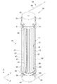
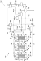
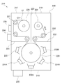
- the heating device 10 includes a closed container 11, a tubular body 12, a heating element 13, a flow path 14, a fluid circulation unit 15, and a control unit 16.
- a heating element 13 is provided outside the cylinder 12, and a flow path 14 is provided inside the cylinder 12, and the fluid flowing through the flow path 14 is heated by the heating element 13 to generate a high temperature. Generate a fluid.
- the closed container 11 has a main body 17 formed in a tubular shape, a fluid inflow chamber 18 provided at one end of the main body 17, and a fluid outflow chamber 19 provided at the other end of the main body 17.
- the side where the fluid inflow chamber 18 is provided with respect to the main body 17 is the lower side, and the side where the fluid outflow chamber 19 is provided with respect to the main body 17 is the upper side.
- the hollow portion 26 is connected to the gas discharge portion 28 via the gas outlet 22.
- the gas discharge portion 28 is composed of a vacuum pump, a pipe connecting the vacuum pump and the hollow portion 26, a valve for adjusting the flow rate of hydrogen-based gas and the pressure in the pipe, and the like. Perform vacuum exhaust.
- the tubular body 12 can have a cylindrical shape having a length of 10 m, a thickness (wall thickness) of 0.005 to 0.010 m, and a diameter of 0.05 m.
- the thickness is preferably appropriately designed based on the temperature and pressure of the fluid flowing through the inside of the tubular body 12 (flow path 14 described later).
- the tubular body 12 can be formed to a desired length, for example, by connecting a plurality of pipe materials in series.
- the number of cylinders 12 is not particularly limited, and may be one or more.
- 800 cylinders 12 can be installed in the closed container 11.
- a plurality of tubular bodies 12 are provided in the hollow portion 26. That is, the heat generating device 10 includes a plurality of tubular bodies 12 provided in the hollow portion 26. In FIG. 1, only one of the plurality of cylinders 12 is shown for simplification of the drawing, and the other cylinders 12 are omitted.
- the heating element 13 When the heated fluid flows into the flow path 14, the heating element 13 is heated via the tubular body 12. As a result, the heating element 13 generates excess heat, and the fluid flowing through the flow path 14 is heated via the tubular body 12. As a result, a high-temperature and high-pressure fluid is generated in the flow path 14, and the high-temperature and high-pressure fluid flows out of the flow path 14.
- the water flowing into the flow path 14 is heated by the heating element 13 that generates excess heat, and flows out from the flow path 14 as, for example, high temperature and high pressure water at 300 ° C. In some cases, a part of the water in the flow path 14 becomes water vapor.
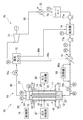
- the circulation line 30 is provided with a cooling unit 32 for cooling the fluid and a heating unit 33 for heating the fluid. That is, the heat generating device 10 further includes a cooling unit 32 and a heating unit 33.
- a reservoir tank 36 for storing water and a pump 40 for circulating water are provided in the circulation line 30.
- each part of the circulation line 30 is provided with a pressure gauge PI, a thermometer TI, and a flow meter FI.
- the number of the pressure gauge PI, the thermometer TI, and the flow meter FI is not particularly limited, but is preferably 1 or more.
- the heating unit 33 is electrically connected to the control unit 16, and the drive is controlled by the control unit 16.
- the heating unit 33 heats water as a fluid flowing into the flow path 14.
- the control unit 16 drives the cooling unit 32 and causes the fluid cooled by the cooling unit 32 to flow into the flow path 14 to lower the temperature of the heating element 13, and drives the heating unit 33 to drive the heating unit 33.
- the temperature rise control is performed to raise the temperature of the heating element 13 by flowing the fluid heated by the above into the flow path 14.
- the control unit 16 adjusts the temperature of the fluid flowing into the flow path 14 by switching between the temperature lowering control and the temperature rising control based on the temperature of the fluid flowing through the circulation line 30.
- the heating element 13 flows out from the flow path 14 as high-temperature and high-pressure water. Since the saturation temperature of water when the pressure is 100 bar is 311 ° C., the water flowing into the flow path 14 does not become water vapor even if the temperature is raised to 300 ° C.
- the fluid circulation unit 15 further has an external fluid line 45 in addition to the circulation line 30.
- Each cylinder 12 provided in the hollow portion 26 of the closed container 11 is heated by the heat of the fluid flowing through the flow path 14 provided inside or the heat of the heating element 13 provided on the outer surface, and the temperature rises. It rises and expands thermally.
- the main body 17 of the closed container 11 is not in contact with the tubular body 12 and the heating element 13, and the temperature rise is suppressed as compared with the tubular body 12, so that the thermal expansion is smaller than that of the tubular body 12. Therefore, thermal stress is generated between the plurality of cylinders 12 and the main body 17 of the closed container 11.
- the external fluid line 45 is for preventing damage due to this thermal stress.
- the flow of the fluid in the closed container 11 will be described with reference to FIG.
- the fluid flowing through the circulation line 30 flows into the fluid inflow chamber 18 from the fluid inlet 23.
- a part of the fluid in the fluid inflow chamber 18 flows from one end of the plurality of cylinders 12 to the flow path 14.
- the fluid is heated by the heating element 13.
- the fluid heated in the flow path 14 flows from the other ends of the plurality of cylinders 12 to the fluid outflow chamber 19, and flows out from the fluid outlet 24 to the circulation line 30.
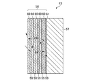
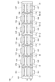
- the multilayer film 58 is provided on the surface of the pedestal 57.
- the multilayer film 58 is formed by a first layer 59 formed of a hydrogen storage metal or a hydrogen storage alloy, and a second layer 60 formed of a hydrogen storage metal, a hydrogen storage alloy or ceramics different from the first layer 59.
- a dissimilar substance interface 61 is formed between the pedestal 57, the first layer 59, and the second layer 60.
- the thickness of the first layer 59 and the thickness of the second layer 60 are preferably less than 1000 nm, respectively. When the thickness of each of the first layer 59 and the second layer 60 is 1000 nm or more, it becomes difficult for hydrogen to permeate through the multilayer film 58. Further, when the thickness of each of the first layer 59 and the second layer 60 is less than 1000 nm, it is possible to maintain a nanostructure that does not exhibit bulk characteristics.
- the thickness of each of the first layer 59 and the second layer 60 is more preferably less than 500 nm. When the thickness of each of the first layer 59 and the second layer 60 is less than 500 nm, it is possible to maintain a nanostructure that does not completely exhibit bulk characteristics.
- the multilayer film 58 has a structure in which the first layer 59 and the second layer 60 are alternately laminated in this order on the surface of the pedestal 57.
- the first layer 59 and the second layer 60 each have five layers. The number of layers of the first layer 59 and the second layer 60 may be changed as appropriate.
- the multilayer film 58 may have a structure in which the second layer 60 and the first layer 59 are alternately laminated in this order on the surface of the pedestal 57.
- the multilayer film 58 may have one or more first layer 59 and one or more second layer 60, and one or more dissimilar substance interfaces 61 may be formed.
- the heating element 13 occludes hydrogen through the pedestal 57 and the multilayer film 58 when the hydrogen-based gas is supplied to the closed container 11.
- the heating element 13 maintains a state in which hydrogen is occluded in the pedestal 57 and the multilayer film 58 even when the supply of the hydrogen-based gas to the closed container 11 is stopped.
- the heating of the heating element 13 is started by the fluid, the hydrogen occluded in the pedestal 57 and the multilayer film 58 is released, and quantum diffusion is performed while hopping the inside of the multilayer film 58. It is known that hydrogen is light and quantum diffuses while hopping the sites (octohedral and tetrahedral sites) occupied by hydrogen of a certain substance A and substance B.
- hydrogen permeates the interface 61 between different substances by quantum diffusion to generate excess heat equal to or higher than the temperature of the fluid.
- the heat generation method using the heat generating device 10 includes a hydrogen storage step of supplying hydrogen-based gas to the hollow portion 26 of the closed container 11 to store hydrogen contained in the hydrogen-based gas in the heating element 13, and a closed container. It has a hydrogen release step of releasing hydrogen stored in the heating element 13 by performing vacuum exhaust of the hollow portion 26 of 11 and heating of the heating element 13. The hydrogen storage step and the hydrogen release step may be repeated.
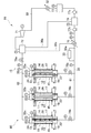
- the circulation line 30 of the heating device 70 includes a steam tank 72, a reservoir tank 73, a deaerator 74, a preheater 75, control valves 76a and 76b, and a pump 77a. , 77b are provided.
- the control valve 76a, the steam tank 72, the steam turbine 71, the cooling unit 32, the reservoir tank 73, the pump 77a, the deaerator 74, and the pump 77b are arranged in this order from the fluid outlet 24 of the closed container 11.
- a preheater 75, a heating unit 33, and a control valve 76b are provided.
- the deaerator 74, the preheater 75, the control valves 76a and 76b, and the pumps 77a and 77b are electrically connected to the control unit 16.
- the heating element 133 has a pedestal 57 and a multilayer film 134.
- the multilayer film 134 further has a third layer 135 in addition to the first layer 59 and the second layer 60.
- the description of the pedestal 57, the first layer 59, and the second layer 60 will be omitted.
- the third layer 135 is formed of a hydrogen storage metal, a hydrogen storage alloy, or ceramics different from those of the first layer 59 and the second layer 60.
- the thickness of the third layer 135 is preferably less than 1000 nm. In FIG.
- first layer 59-third layer 135-second layer 60 Pd-CaO-Ni, Pd-Y 2 O 3 -Ni, Pd-TiC-Ni, Pd-LaB 6 -Ni, Ni-CaO-Cu, Ni-Y 2 O 3 -Cu, Ni-TiC-Cu, Ni-LaB 6 -Cu, Ni-Co-Cu, Ni-CaO-Cr, Ni-Y 2 O 3 -Cr, Ni-TiC-Cr, Ni-LaB 6 -Cr, Ni-CaO-Fe, Ni-Y 2 O 3 -Fe, Ni -TiC-Fe, Ni-LaB 6 -Fe, Ni-Cr-Fe, Ni-CaO-Mg, Ni-Y 2 O 3 -Mg, Ni-TiC-Mg, Ni-LaB 6 -Mg,
- the first layer 59 and the fourth layer 145 are laminated in this order.
- the first layer 59, the second layer 60, the third layer 135, and the fourth layer 145 have the first layer 59, the fourth layer 145, the first layer 59, the third layer 135, and the first layer 145 on the surface of the pedestal 57.
- the first layer 59 and the second layer 60 may be laminated in this order. That is, in the multilayer film 144, the second layer 60, the third layer 135, and the fourth layer 145 are laminated in an arbitrary order, and the second layer 60, the third layer 135, and the fourth layer 145 are placed in the first layer. It has a laminated structure with one layer 59.
- the multilayer film 144 may have one or more fourth layers 145.
- the dissimilar substance interface 146 formed between the first layer 59 and the fourth layer 145 allows hydrogen atoms to permeate in the same manner as the dissimilar substance interface 61 and the dissimilar substance interface 136.
- the fourth layer 145 is formed of, for example, Ni, Pd, Cu, Cr, Fe, Mg, Co, an alloy thereof, SiC, CaO, Y 2 O 3 , TiC, or LaB 6 .
- the alloy forming the fourth layer 145 is preferably an alloy composed of two or more of Ni, Pd, Cu, Cr, Fe, Mg, and Co.
- an alloy obtained by adding an additive element to Ni, Pd, Cu, Cr, Fe, Mg, and Co may be used as the alloy forming the fourth layer 145.
- CO 2 contained in the exhaust gas is adsorbed on an adsorbent such as activated carbon or zeolite, and the adsorbent on which the CO 2 is adsorbed is heated to desorb CO 2 from the adsorbent.
- a fluid heated by a heating element can be used as a heat energy source for heating the absorption liquid that has absorbed CO 2.
- a fluid heated by a heating element can be used as a heat energy source for heating the adsorbent on which CO 2 is adsorbed in the physical adsorption method.
- CH 4 methane
- H 2 methane
- CH 4 is produced from the raw material gas by bringing the raw material gas containing CO 2 and H 2 into contact with the catalyst using a catalyst that promotes the reaction between CO 2 and H 2 (methanation reaction). If the temperature of the gas is low, the reaction does not proceed sufficiently. Therefore, the metanation reaction can be allowed to proceed by using the fluid heated by the heating element as the heat energy source as the heat energy source for heating the raw material gas containing CO 2 and H 2.
- ammonium iodide NH 4 I
- a fluid heated by a heating element can be used as a heat energy source for thermally decomposing ammonium iodide.
- FIG. 22 is a heating element manufacturing apparatus 150 that manufactures the heating element 13 by using a sputtering method.
- the heating element manufacturing apparatus 150 implements a DC (Direct Current) magnetron sputtering method as a sputtering method, and directly forms the heating element 13 on the outer surface of the tubular body 12.
- DC Direct Current
- the heating element manufacturing apparatus 150 carries a plurality of cylinders 12 into the loading chamber 151 and directly forms the heating element 13 on the outer surface of each cylinder 12, but loads one cylinder 12. It may be carried into the chamber 151 and the heating element 13 may be directly formed on the outer surface of the tubular body 12.
- the heating element manufacturing apparatus 150 is provided between the first gate valve 161 provided between the load chamber 151 and the preheating chamber 152, and the first gate valve 161 provided between the preheating chamber 152 and the spatter etching chamber 153.
- the first gate valve 161 opens and closes the first loading / unloading section 171 between the load chamber 151 and the preheating chamber 152.
- the second gate valve 162 opens and closes the second carry-in / out portion 172 between the preheating chamber 152 and the sputter etching chamber 153.
- the third gate valve 163 opens and closes the third carry-in / out portion 173 between the sputtering etching chamber 153 and the pedestal forming chamber 154.
- the fourth gate valve 164 opens and closes the fourth carry-in / out portion 174 between the pedestal forming chamber 154 and the first layer forming chamber 155.
- the load chamber 151 has a carry-in unit 191 for carrying in the cylinder 12, and after the cylinder 12 is carried in from the carry-in unit 191, the first vacuum generation unit is closed with the carry-in unit 191 and the first gate valve 161 closed. It is evacuated by 181. After the vacuum exhaust of the load chamber 151, the first gate valve 161 is opened, and the tubular body 12 is conveyed from the load chamber 151 to the preheating chamber 152 via the first loading / unloading section 171.
- the sputter etching chamber 153 is evacuated by the third vacuum generating unit 183 with the second gate valve 162 and the third gate valve 163 closed.
- the sputter-etching chamber 153 has a sputter-etching electrode 193, and sputter-etches the cylinder 12 with the spatter-etching electrode 193 while rotating the cylinder 12.
- the sputter etching electrode 193 is formed on the surface of the tubular body 12 by, for example, adjusting the flow rate of Ar gas so that the pressure of Ar is about 0.1 to 1 Pa and applying a high frequency (RF; Radio Frequency) of 13.56 MHz. Removes organic substances and metal oxides.
- the third gate valve 163 is opened, and the tubular body 12 is conveyed from the sputter etching chamber 153 to the pedestal forming chamber 154 via the third carry-in / out portion 173.
- the pedestal forming sputtering electrode 194 is formed on the cylinder 12 by, for example, adjusting the flow rate of Ar gas to set the Ar pressure to about 0.1 to 1 Pa and applying DC power of about 0.1 to 500 kW / m 2.
- the pedestal 57 is formed on the surface. The thickness of the pedestal 57 can be controlled by adjusting the magnitude of the DC power and the rotation speed of the cylinder 12.
- the first layer forming chamber 155 is evacuated to, for example, about 1E-5Pa by the fifth vacuum generating unit 185 with the fourth gate valve 164 and the fifth gate valve 165 closed.
- the first layer forming chamber 155 has a first layer film forming sputtering electrode 195, and forms the first layer 59 on the pedestal 57 by the first layer forming sputtering electrode 195 while rotating the tubular body 12.
- the first layer film forming sputtering electrode 195 has a target material (not shown) of a hydrogen storage metal or a hydrogen storage alloy forming the first layer 59.
- the front surface of the target material faces the pedestal 57.
- a magnet (not shown) is arranged on the back surface of the target material.
- the first layer film forming sputtering electrode 195 is a pedestal, for example, by adjusting the flow rate of Ar gas to set the Ar pressure to about 0.1 to 1 Pa and applying DC power to about 0.1 to 500 kW / m 2.
- the first layer 59 is formed on the 57.
- the thickness of the first layer 59 can be controlled by adjusting the magnitude of the DC power and the rotation speed of the cylinder 12.
- the second layer forming chamber 156 is evacuated to, for example, about 1E-5Pa by the sixth vacuum generating unit 186 with the fifth gate valve 165 and the sixth gate valve 166 closed.
- the second layer forming chamber 156 has a second layer film forming sputtering electrode 196, and forms the second layer 60 on the pedestal 57 by the second layer film forming sputtering electrode 196 while rotating the tubular body 12.
- the second layer film forming sputter electrode 196 has a target material (not shown) of a hydrogen storage metal, a hydrogen storage alloy, or a ceramic that forms the second layer 60.
- the front surface of the target material faces the pedestal 57.
- a magnet (not shown) is arranged on the back surface of the target material.
- the second layer film forming sputtering electrode 196 is a pedestal, for example, by adjusting the flow rate of Ar gas to set the Ar pressure to about 0.1 to 1 Pa and applying DC power to about 0.1 to 500 kW / m 2.
- the second layer 60 is formed on the 57.
- the second layer film forming sputtering electrode 196 is configured to apply RF.
- a multilayer film 58 (see FIG. 5) composed of the first layer 59 and the second layer 60 is formed on the surface of the pedestal 57. In this way, the heating element 13 is directly formed on the outer surface of the tubular body 12.
- the thickness of the second layer 60 can be controlled by adjusting the magnitude of the DC power and the rotation speed of the cylinder 12.
- the sixth gate valve 166 is opened, and the tubular body 12 is conveyed from the second layer forming chamber 156 to the unload chamber 157 via the sixth loading / unloading portion 176.
- the unload chamber 157 has a carry-out unit 197 for carrying out the tubular body 12, and the sixth vacuum generation part 186 is opened to the atmosphere with the carry-out part 197 and the sixth gate valve 166 closed. From the unload chamber 157 in the atmospheric pressure state, the tubular body 12 on which the heating element 13 is formed can be taken out via the carry-out portion 197.
- the heating element manufacturing apparatus 150 is provided with first to seventh vacuum generating units 181 to 187 that evacuate each processing chamber, but the vacuum generating unit may be shared by several processing chambers. Good.
- the pressure in each processing chamber can be controlled, for example, by adjusting the flow rate of Ar gas using an orifice valve.
- the rotation speed of the cylinder 12 is set based on the film thickness, etching rate or film formation rate to be etched or filmed.
- the film thickness to be etched or filmed is X (nm) and the etching rate or film formation rate is Y (nm / min)
- the heating element manufacturing device 150 can be made smaller as a whole by being configured to carry in a plurality of short tubular bodies 12 having a length of, for example, about 50 cm to 2 m.
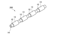
- the heating unit 200 may be configured by connecting short cylinders 12 on which the heating element 13 is formed.
- the heating element manufacturing device 150 is not limited to the one that manufactures the heating element 13 having a structure in which the multilayer film 58 is formed on the pedestal 57.
- a heating element 133 having a structure in which a multilayer film 134 is formed on a pedestal 57, or a heating element 143 having a structure in which a multilayer film 144 is formed on a pedestal 57 may be manufactured.
- the heating element manufacturing apparatus for manufacturing the heating element 133 has a third layer film forming sputter electrode for forming the third layer 135 on the pedestal 57 in addition to the first layer forming chamber 155 and the second layer forming chamber 156.
- a layer forming chamber is further provided.
- the third layer film forming sputtering electrode has a target material of a hydrogen storage metal or a hydrogen storage alloy forming the third layer 135. Similar to the first layer film forming sputtering electrode or the second layer film forming sputtering electrode, the third layer film forming sputtering electrode has the thickness of the third layer 135 by adjusting the magnitude of the DC power and the rotation speed of the cylinder 12. Can be controlled.
- the thickness of the pedestal 57 constituting the heating elements 13, 133, 143 is not particularly limited and can be changed as appropriate.
- a film-shaped heating element (hereinafter referred to as a film-shaped heating element) can be formed by thinning the pedestal 57 to form a film and providing the multilayer films 58, 134, 144 on the film-shaped pedestal 57. ..
- the film-shaped heating element will be described in detail.
- the film-shaped heating element 213 is wound around the outer surface of the tubular body 12.
- the film-shaped heating element 213 may be spirally wound around the outer surface of the tubular body 12 with a gap.
- the film-shaped heating element 213 has a spiral shape on the outer surface of the tubular body 12 so that at least a part of the film-shaped heating elements 213 adjacent to each other in the central axis C direction of the tubular body 12 overlaps in the radial direction of the tubular body 12. You may wrap it around.
- the film-shaped heating element 213 has the same structure as the heating element 13 (see FIG. 5). That is, the film-shaped heating element 213 has a pedestal 57 and a multilayer film 58.
- the pedestal 57 and the multilayer film 58 constituting the film-shaped heating element 213 are in the form of a film.
- the thickness of the pedestal 57 is preferably in the range of 1 ⁇ m or more and 5000 ⁇ m or less, and more preferably in the range of 100 ⁇ m or more and 600 ⁇ m or less.
- the thickness of the multilayer film 58 is preferably in the range of 0.02 ⁇ m or more and 10 ⁇ m or less, and more preferably in the range of 2 ⁇ m or more and 6 ⁇ m or less.
- the thickness of the film-shaped heating element 213 is preferably in the range of 1.02 ⁇ m or more and 5010 ⁇ m or less, and more preferably in the range of 102 ⁇ m or more and 606 ⁇ m or less.
- the thickness of the pedestal 57, the thickness of the multilayer film 58, and the thickness of the film-shaped heating element 213 are not limited to the above values, and are appropriately designed so that a desired output can be obtained as a heating device using the film-shaped heating element 213. be able to.
- the film-shaped heating element 213 has the same structure as the heating element 13 in this example, but may have the same structure as the heating element 133 (see FIG. 19), that is, a pedestal 57 and a multilayer film 134. Further, the film-shaped heating element 213 may have the same structure as the heating element 143 (see FIG. 20), that is, one having a pedestal 57 and a multilayer film 144.
- the multilayer film 134 or the multilayer film 144 constituting the film-shaped heating element 213 is in the form of a film.
- the film-shaped heating element 213 and the tubular body 12 are joined by, for example, spot welding.
- the film-shaped heating element 213 and the tubular body 12 are joined by spot welding the film-shaped heating element 213 around the outer surface of the tubular body 12 at equal intervals in the central axis C direction of the tubular body 12.
- the spot-welded portion has a high temperature, the characteristics of the film-shaped heating element 213 are hardly deteriorated because the diameter of the spot-welded portion is about 1 mm and the time in the high temperature state is several seconds.
- the location where the film-shaped heating element 213 and the tubular body 12 are joined is not particularly limited.
- the film-shaped heating element 213 has the pedestal 57 and the multilayer film 58, it has the same action and effect as the heating element 13. That is, since the film-shaped heating element 213 uses hydrogen to generate heat, it does not generate greenhouse gases such as carbon dioxide. Further, the hydrogen used to generate heat in the film-shaped heating element 213 is inexpensive because it can be generated from water. Further, the heat generated by the film-shaped heating element 213 is considered safe because there is no chain reaction unlike the fission reaction. Therefore, the film heating element 213 can be used as an inexpensive, clean, and safe energy source. Further, the film-shaped heating element 213 is excellent in followability to a curved surface while having flexibility because the pedestal 57 and the multilayer film 58 are in the form of a film.
- FIG. 25 is a film-shaped heating element manufacturing apparatus 215 that manufactures a film-shaped heating element 213 using a sputtering method.
- the film-shaped heating element manufacturing apparatus 215 implements a DC magnetron sputtering method as a sputtering method in this example.
- the film-shaped heating element manufacturing apparatus 215 continuously conveys a long film-shaped pedestal 57 by a roller-to-roller method, and forms a multilayer film 58 on the surface of the pedestal 57.
- the sputtering gas is argon (Ar) gas in this example, but a known gas may be used.
- Ar argon
- the shape and material of the vacuum chamber 220 are not particularly limited as long as they can withstand a reduced pressure state.
- the unwinding chamber 217 includes an unwinding roller 226 around which a long film-shaped pedestal 57 is wound, a first conveying roller portion 227 that conveys the pedestal 57 unwound from the unwinding roller 226, and a first conveying roller. It has a heating unit 228 that heats the pedestal 57 conveyed by the unit 227.
- the unwinding roller 226 has a motor (not shown) and is rotated by driving the motor.
- the first transport roller unit 227 is composed of, for example, a free roller and a tension measuring roller.
- the heating unit 228 removes the water adsorbed on the surface of the pedestal 57 by heating the pedestal 57 so that the surface temperature is, for example, 200 to 350 ° C.
- the heating unit 228 is not particularly limited as long as it can heat the pedestal 57 to a desired temperature, and for example, a lamp heating method, an infrared heating method, an induction heating method, or the like can be used.
- the film forming chamber 218 forms a film forming roller 229 that conveys the pedestal 57 carried out from the unwinding chamber 217, a sputter etching electrode 230 that sputter etches the surface of the pedestal 57, and a first layer 59 on the pedestal 57. It has first-layer film-forming sputtering electrodes 231A and 231B, and second-layer film-forming sputtering electrodes 232A and 232B that form a second layer 60 on a pedestal 57.
- sputter etching electrode 230 for example, by adjusting the flow rate of Ar gas to set the Ar pressure to about 0.1 to 1 Pa and applying RF of 13.56 MHz, organic substances, metal oxides, etc. on the surface of the pedestal 57 can be obtained. To remove.
- the second layer film forming sputtering electrode 232A and the second layer film forming sputtering electrode 232B have the same configuration as each other.
- the second layer film-forming sputter electrodes 232A and 232B have a target material (not shown) of a hydrogen storage metal, a hydrogen storage alloy, or a ceramic that forms the second layer 60.
- the front surface of the target material faces the pedestal 57.
- a magnet (not shown) is arranged on the back surface of the target material.
- the second layer film forming sputtering electrodes 232A and 232B for example, by adjusting the flow rate of Ar gas to set the Ar pressure to about 0.1 to 1 Pa and applying DC power to about 0.1 to 500 kW / m 2.
- the second layer film forming sputtering electrode 232A forms the second layer 60 on the surface of the first layer 59 formed by the first layer film forming sputtering electrode 231A.
- the first layer film forming sputtering electrode 231B forms the first layer 59 on the surface of the second layer 60 formed by the second layer film forming sputtering electrode 232A.
- the second layer film forming sputtering electrode 232B forms the second layer 60 on the surface of the first layer 59 formed by the first layer film forming sputtering electrode 231B. In this way, in the film forming chamber 218, a multilayer film 58 composed of the first layer 59 and the second layer 60 is formed on the surface of the pedestal 57.
- the take-up chamber 219 has a second transport roller portion 233 that conveys the pedestal 57 carried out from the film forming chamber 218, and a take-up roller 234 that winds up the pedestal 57 conveyed by the second transport roller portion 233.
- the film-like material wound around the take-up roller 234 is the film-like heating element 213.
- the second transport roller unit 233 is composed of, for example, a free roller and a tension measuring roller.
- the take-up roller 234 has a motor (not shown) and is rotated by driving the motor. The tension based on the peripheral speed difference between the take-up roller 234 and the film forming roller 229 is measured by the tension measuring roller of the second transport roller portion 233.
- a plurality of short film heating elements 213 are prepared by cutting a long film heating element 213 to a predetermined length, and a plurality of short film heating elements 213 are placed on the outer surface of one cylinder 12 with each other. It may be provided at intervals.
- step processing for example, by turning the power ON / OFF or adjusting the input power, the time for heating, sputter etching, and film formation can be set independently. Further, the time for forming the film may be set by opening and closing the shutter that shields the target material.
- the fourth layer film forming sputtering electrode of the fourth layer 145 is formed by adjusting the magnitude of DC power and the transport speed of the pedestal 57. The thickness can be controlled.
Abstract
Description
図1において、発熱装置10は、密閉容器11と、筒体12と、発熱体13と、流路14と、流体循環部15と、制御部16とを備える。発熱装置10は、筒体12の外部に発熱体13が設けられ、筒体12の内部に流路14が設けられており、流路14を流通する流体を発熱体13により加熱し、高温の流体を生成する。 [First Embodiment]
In FIG. 1, the
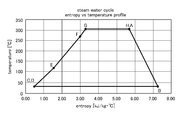
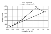
上記第1実施形態では、流路14に流入させた水を発熱体13により加熱して高温高圧水を生成しているが、第2実施形態は、流路14に流入させた水を発熱体13により加熱して過熱蒸気を生成し、この過熱蒸気を蒸気タービンの作動流体として利用することにより発電を行うように構成したものである。上記第1実施形態と同じ部材を用いているものについては、同符号を付して説明を省略する。 [Second Embodiment]
In the first embodiment, the water flowing into the
上記第2実施形態の発熱装置70は1つの発熱モジュール55を備えるものであるが、第3実施形態は複数の発熱モジュール55を接続したものである。この例では3つの発熱モジュール55を接続する場合について説明するが、発熱モジュール55の数は特に限定されず、所望の出力が得られるように増減することができる。上記各実施形態と同じ部材を用いているものについては、同符号を付して説明を省略する。 [Third Embodiment]
The

第4実施形態は、流体として気体を使用するように構成したものである。この例では流体として空気を使用する場合について説明するが、空気以外の気体を用いてもよい。上記各実施形態と同じ部材を用いているものについては、同符号を付して説明を省略する。 [Fourth Embodiment]
The fourth embodiment is configured to use a gas as the fluid. In this example, the case where air is used as the fluid will be described, but a gas other than air may be used. Those using the same members as those in each of the above embodiments are designated by the same reference numerals and the description thereof will be omitted.
第5実施形態は、高温空気を利用してボイラーで過熱蒸気を発生させ、この過熱蒸気を蒸気タービンの作動流体として利用することにより発電を行うように構成したものである。上記各実施形態と同じ部材を用いているものについては、同符号を付して説明を省略する。 [Fifth Embodiment]
In the fifth embodiment, superheated steam is generated in a boiler using high-temperature air, and the superheated steam is used as a working fluid of a steam turbine to generate electricity. Those using the same members as those in each of the above embodiments are designated by the same reference numerals and the description thereof will be omitted.
上記第5実施形態の発熱装置100は1つの発熱モジュール55を備えるものであるが、第6実施形態は複数の発熱モジュール55を接続したものである。この例では3つの発熱モジュール55a~55cを接続する場合について説明するが、発熱モジュール55の数は特に限定されず、所望の出力が得られるように増減することができる。上記各実施形態と同じ部材を用いているものについては、同符号を付して説明を省略する。 [Sixth Embodiment]
The
11 密閉容器
12 筒体
13,133,143 発熱体
14 流路
15 流体循環部
16 制御部
26 中空部
30 循環ライン
32,92 冷却部
33 加熱部
45 外部流体ライン
55,55a~55c 発熱モジュール
57 台座
58,134,144 多層膜
59 第1層
60 第2層
61,136,146 異種物質界面
71,104 蒸気タービン(流体利用装置)
79,89,119,129 熱利用システム
101 熱回収ライン
135 第3層
145 第4層
150 発熱体製造装置
213,243 フィルム状発熱体
215 フィルム状発熱体製造装置 10, 70, 80, 90, 100, 120
79, 89, 119, 129
Claims (12)
- 中空の密閉容器と、
前記密閉容器の内面により形成される中空部に設けられた筒体と、
前記筒体の外面に設けられ、前記中空部に供給される水素系ガスに含まれる水素の吸蔵と放出とにより熱を発生する発熱体と、
前記筒体の内面により形成され、前記発熱体との間で熱交換を行う流体が流通する流路と
を備え、
前記発熱体は、水素吸蔵金属、水素吸蔵合金、またはプロトン導電体により形成された台座と、前記台座に設けられた多層膜とを有し、
前記多層膜は、水素吸蔵金属または水素吸蔵合金により形成され、厚みが1000nm未満である第1層と、前記第1層とは異なる水素吸蔵金属、水素吸蔵合金、またはセラミックスにより形成され、厚みが1000nm未満である第2層とを有する発熱装置。 Hollow airtight container and
A cylinder provided in a hollow portion formed by the inner surface of the closed container and
A heating element provided on the outer surface of the cylinder and generating heat by storing and releasing hydrogen contained in the hydrogen-based gas supplied to the hollow portion.
It is provided with a flow path formed by the inner surface of the cylinder and through which a fluid that exchanges heat with the heating element flows.
The heating element has a pedestal formed of a hydrogen storage metal, a hydrogen storage alloy, or a proton conductor, and a multilayer film provided on the pedestal.
The multilayer film is formed of a first layer having a thickness of less than 1000 nm, which is formed of a hydrogen storage metal or a hydrogen storage alloy, and a hydrogen storage metal, a hydrogen storage alloy, or ceramics different from the first layer, and has a thickness of less than 1000 nm. A heat generating device having a second layer having a diameter of less than 1000 nm. - 前記流路と接続して前記筒体の内部と外部との間で前記流体を循環させる循環ラインを有する流体循環部と、
前記循環ラインに設けられ、前記流体を冷却する冷却部と、
前記循環ラインに設けられ、前記流体を加熱する加熱部と、
前記冷却部を駆動し、冷却された前記流体により前記発熱体の温度を低下させる降温制御と、前記加熱部を駆動し、加熱された前記流体により前記発熱体の温度を上昇させる昇温制御とを行う制御部とをさらに備える請求項1に記載の発熱装置。 A fluid circulation unit having a circulation line connected to the flow path and circulating the fluid between the inside and the outside of the cylinder.
A cooling unit provided on the circulation line to cool the fluid,
A heating unit provided in the circulation line to heat the fluid, and
Temperature lowering control that drives the cooling unit and lowers the temperature of the heating element by the cooled fluid, and temperature rise control that drives the heating unit and raises the temperature of the heating element by the heated fluid. The heating device according to claim 1, further comprising a control unit for performing the above. - 前記流体循環部は、前記密閉容器の外面に設けられ、前記循環ラインと接続して前記流体の一部が流通する外部流体ラインをさらに有する請求項2に記載の発熱装置。 The heat generating device according to claim 2, wherein the fluid circulation unit is provided on the outer surface of the closed container and further has an external fluid line connected to the circulation line and through which a part of the fluid flows.
- 前記第1層は、Ni、Pd、Cu、Mn、Cr、Fe、Mg、Co、これらの合金のうちいずれかにより形成され、
前記第2層は、Ni、Pd、Cu、Mn、Cr、Fe、Mg、Co、これらの合金、SiCのうちいずれかにより形成される請求項1~3のいずれか1項に記載の発熱装置。 The first layer is formed of Ni, Pd, Cu, Mn, Cr, Fe, Mg, Co, or any of these alloys.
The heat generating device according to any one of claims 1 to 3, wherein the second layer is formed of any one of Ni, Pd, Cu, Mn, Cr, Fe, Mg, Co, an alloy thereof, and SiC. .. - 前記多層膜は、前記第1層および前記第2層に加え、前記第1層および前記第2層とは異なる水素吸蔵金属、水素吸蔵合金、またはセラミックスにより形成され、厚みが1000nm未満である第3層を有する請求項4に記載の発熱装置。 The multilayer film is formed of a hydrogen storage metal, a hydrogen storage alloy, or ceramics different from the first layer and the second layer in addition to the first layer and the second layer, and has a thickness of less than 1000 nm. The heat generating device according to claim 4, which has three layers.
- 前記第3層は、CaO、Y2O3、TiC、LaB6、SrO、BaOのうちいずれかにより形成される請求項5に記載の発熱装置。 The heat generating device according to claim 5, wherein the third layer is formed of any one of CaO, Y 2 O 3 , TiC, LaB 6, SrO, and BaO.
- 前記多層膜は、前記第1層、前記第2層および前記第3層に加え、前記第1層、前記第2層および前記第3層とは異なる水素吸蔵金属または水素吸蔵合金により形成され、厚みが1000nm未満である第4層を有する請求項6に記載の発熱装置。 The multilayer film is formed of a hydrogen storage metal or a hydrogen storage alloy different from the first layer, the second layer and the third layer in addition to the first layer, the second layer and the third layer. The heat generating device according to claim 6, further comprising a fourth layer having a thickness of less than 1000 nm.
- 前記第4層は、Ni、Pd、Cu、Cr、Fe、Mg、Co、これらの合金、SiC、CaO、Y2O3、TiC、LaB6、SrO、BaOのうちいずれかにより形成される請求項7に記載の発熱装置。 The fourth layer is claimed to be formed of any of Ni, Pd, Cu, Cr, Fe, Mg, Co, alloys thereof, SiC, CaO, Y 2 O 3 , TiC, LaB 6, SrO, and BaO. Item 7. The heat generating device according to item 7.
- 前記台座および前記多層膜はフィルム状であり、
前記発熱体は、前記筒体の外面に巻き付けられている請求項1~8のいずれか1項に記載の発熱装置。 The pedestal and the multilayer film are in the form of a film and are in the form of a film.
The heating element according to any one of claims 1 to 8, wherein the heating element is wound around an outer surface of the cylinder. - 請求項1~9のいずれか1項に記載の発熱装置と、
前記発熱体により加熱された前記流体を利用する流体利用装置とを備える熱利用システム。 The heat generating device according to any one of claims 1 to 9,
A heat utilization system including a fluid utilization device that utilizes the fluid heated by the heating element. - 水素吸蔵金属、水素吸蔵合金、またはプロトン導電体により形成されたフィルム状の台座と、
前記台座に設けられたフィルム状の多層膜とを有し、
前記多層膜は、水素吸蔵金属または水素吸蔵合金により形成され、厚みが1000nm未満である第1層と、前記第1層とは異なる水素吸蔵金属、水素吸蔵合金、またはセラミックスにより形成され、厚みが1000nm未満である第2層とを有するフィルム状発熱体。 A film-like pedestal formed of a hydrogen storage metal, a hydrogen storage alloy, or a proton conductor,
It has a film-like multilayer film provided on the pedestal, and has
The multilayer film is formed of a first layer having a thickness of less than 1000 nm, which is formed of a hydrogen storage metal or a hydrogen storage alloy, and a hydrogen storage metal, a hydrogen storage alloy, or ceramics different from the first layer, and has a thickness of less than 1000 nm. A film-like heating element having a second layer having a diameter of less than 1000 nm. - 前記台座の厚みは、1μm以上5000μm以下の範囲内であり、
前記多層膜の厚みは、0.02μm以上10μm以下の範囲内である請求項11に記載のフィルム状発熱体。 The thickness of the pedestal is in the range of 1 μm or more and 5000 μm or less.
The film-shaped heating element according to claim 11, wherein the thickness of the multilayer film is in the range of 0.02 μm or more and 10 μm or less.
Priority Applications (9)
| Application Number | Priority Date | Filing Date | Title |
|---|---|---|---|
| CN202080080722.6A CN114746712A (en) | 2019-11-19 | 2020-11-18 | Heat generating device, heat utilization system, and film-shaped heat generating body |
| AU2020389304A AU2020389304A1 (en) | 2019-11-19 | 2020-11-18 | Heat generation device, heat utilization system and film-like heat generation element |
| EP20890402.9A EP4063319A4 (en) | 2019-11-19 | 2020-11-18 | Heat generation device, heat utilization system and film-like heat generation element |
| BR112022009628A BR112022009628A2 (en) | 2019-11-19 | 2020-11-18 | HEAT GENERATING DEVICE, HEAT USE SYSTEM AND HEAT GENERATING ELEMENT AS A FILM |
| US17/778,141 US20230003461A1 (en) | 2019-11-19 | 2020-11-18 | Heat generation device, heat utilization system and film-like heat generation element |
| CA3158751A CA3158751A1 (en) | 2019-11-19 | 2020-11-18 | Heat generation device, heat utilization system and film-like heat generation element |
| KR1020227020309A KR20220103990A (en) | 2019-11-19 | 2020-11-18 | Heating devices, heat utilization systems and film-type heating elements |
| JP2021558432A JPWO2021100784A1 (en) | 2019-11-19 | 2020-11-18 | |
| TW109140560A TW202136146A (en) | 2019-11-19 | 2020-11-19 | Heat generation device, heat utilization system and film-like heat generation element |
Applications Claiming Priority (2)
| Application Number | Priority Date | Filing Date | Title |
|---|---|---|---|
| JP2019208483 | 2019-11-19 | ||
| JP2019-208483 | 2019-11-19 |
Publications (1)
| Publication Number | Publication Date |
|---|---|
| WO2021100784A1 true WO2021100784A1 (en) | 2021-05-27 |
Family
ID=75981288
Family Applications (1)
| Application Number | Title | Priority Date | Filing Date |
|---|---|---|---|
| PCT/JP2020/043076 WO2021100784A1 (en) | 2019-11-19 | 2020-11-18 | Heat generation device, heat utilization system and film-like heat generation element |
Country Status (10)
| Country | Link |
|---|---|
| US (1) | US20230003461A1 (en) |
| EP (1) | EP4063319A4 (en) |
| JP (1) | JPWO2021100784A1 (en) |
| KR (1) | KR20220103990A (en) |
| CN (1) | CN114746712A (en) |
| AU (1) | AU2020389304A1 (en) |
| BR (1) | BR112022009628A2 (en) |
| CA (1) | CA3158751A1 (en) |
| TW (1) | TW202136146A (en) |
| WO (1) | WO2021100784A1 (en) |
Cited By (4)
| Publication number | Priority date | Publication date | Assignee | Title |
|---|---|---|---|---|
| WO2022234798A1 (en) * | 2021-05-07 | 2022-11-10 | 株式会社クリーンプラネット | Heat generating device |
| WO2022234797A1 (en) * | 2021-05-07 | 2022-11-10 | 株式会社クリーンプラネット | Heat generation device |
| WO2023026889A1 (en) * | 2021-08-27 | 2023-03-02 | 株式会社クリーンプラネット | Heat-generating device and boiler |
| WO2023145282A1 (en) * | 2022-01-31 | 2023-08-03 | 株式会社クリーンプラネット | Heat utilization system and heat generating device |
Citations (12)
| Publication number | Priority date | Publication date | Assignee | Title |
|---|---|---|---|---|
| JPS5292144A (en) * | 1976-01-29 | 1977-08-03 | Agency Of Ind Science & Technol | Electric power accumulating-type heating equipment using metal-hydroge n compounds |
| JPH06257864A (en) * | 1993-03-01 | 1994-09-16 | Nippon Telegr & Teleph Corp <Ntt> | Heat generating device |
| JPH1172200A (en) * | 1997-08-29 | 1999-03-16 | Sanyo Electric Co Ltd | Hydrogen storage alloy housing vessel |
| WO2000077266A1 (en) * | 1999-06-11 | 2000-12-21 | Sumitomo Electric Industries, Ltd. | Hydrogen-occluding layered material |
| JP2004025012A (en) * | 2002-06-25 | 2004-01-29 | Yoichi Kadokami | Gas storage material, and method of storing and discharging gas |
| JP2004053208A (en) * | 2002-07-23 | 2004-02-19 | Denso Corp | Heating device in hydrogen consumption device |
| JP2004077200A (en) * | 2002-08-12 | 2004-03-11 | Mitsubishi Heavy Ind Ltd | Element transmuter and method for manufacturing it |
| WO2015008859A2 (en) * | 2013-07-18 | 2015-01-22 | 水素技術応用開発株式会社 | Reactant, heating device, and heating method |
| WO2018062115A1 (en) * | 2016-09-28 | 2018-04-05 | 株式会社クリーンプラネット | Heat generating system |
| WO2018230447A1 (en) * | 2017-06-15 | 2018-12-20 | 株式会社クリーンプラネット | Heat generating device and method for generating heat |
| WO2020122097A1 (en) * | 2018-12-11 | 2020-06-18 | 株式会社クリーンプラネット | Heat utilization system, and heat generating device |
| WO2020122098A1 (en) * | 2018-12-11 | 2020-06-18 | 株式会社クリーンプラネット | Heat utilization system, and heat generating device |
-
2020
- 2020-11-18 US US17/778,141 patent/US20230003461A1/en active Pending
- 2020-11-18 CA CA3158751A patent/CA3158751A1/en active Pending
- 2020-11-18 AU AU2020389304A patent/AU2020389304A1/en active Pending
- 2020-11-18 JP JP2021558432A patent/JPWO2021100784A1/ja active Pending
- 2020-11-18 KR KR1020227020309A patent/KR20220103990A/en unknown
- 2020-11-18 BR BR112022009628A patent/BR112022009628A2/en unknown
- 2020-11-18 EP EP20890402.9A patent/EP4063319A4/en active Pending
- 2020-11-18 WO PCT/JP2020/043076 patent/WO2021100784A1/en unknown
- 2020-11-18 CN CN202080080722.6A patent/CN114746712A/en active Pending
- 2020-11-19 TW TW109140560A patent/TW202136146A/en unknown
Patent Citations (15)
| Publication number | Priority date | Publication date | Assignee | Title |
|---|---|---|---|---|
| JPS5292144A (en) * | 1976-01-29 | 1977-08-03 | Agency Of Ind Science & Technol | Electric power accumulating-type heating equipment using metal-hydroge n compounds |
| JPH06257864A (en) * | 1993-03-01 | 1994-09-16 | Nippon Telegr & Teleph Corp <Ntt> | Heat generating device |
| JPH1172200A (en) * | 1997-08-29 | 1999-03-16 | Sanyo Electric Co Ltd | Hydrogen storage alloy housing vessel |
| WO2000077266A1 (en) * | 1999-06-11 | 2000-12-21 | Sumitomo Electric Industries, Ltd. | Hydrogen-occluding layered material |
| JP2004025012A (en) * | 2002-06-25 | 2004-01-29 | Yoichi Kadokami | Gas storage material, and method of storing and discharging gas |
| JP2004053208A (en) * | 2002-07-23 | 2004-02-19 | Denso Corp | Heating device in hydrogen consumption device |
| JP2004077200A (en) * | 2002-08-12 | 2004-03-11 | Mitsubishi Heavy Ind Ltd | Element transmuter and method for manufacturing it |
| WO2015008859A2 (en) * | 2013-07-18 | 2015-01-22 | 水素技術応用開発株式会社 | Reactant, heating device, and heating method |
| WO2018062115A1 (en) * | 2016-09-28 | 2018-04-05 | 株式会社クリーンプラネット | Heat generating system |
| WO2018230447A1 (en) * | 2017-06-15 | 2018-12-20 | 株式会社クリーンプラネット | Heat generating device and method for generating heat |
| JP6548102B2 (en) * | 2017-06-15 | 2019-07-24 | 株式会社クリーンプラネット | Heating device and heating method |
| JP6696096B2 (en) * | 2017-06-15 | 2020-05-20 | 株式会社クリーンプラネット | Heating device and heating method |
| WO2020122097A1 (en) * | 2018-12-11 | 2020-06-18 | 株式会社クリーンプラネット | Heat utilization system, and heat generating device |
| WO2020122098A1 (en) * | 2018-12-11 | 2020-06-18 | 株式会社クリーンプラネット | Heat utilization system, and heat generating device |
| JP6749035B1 (en) * | 2018-12-11 | 2020-09-02 | 株式会社クリーンプラネット | Heat utilization system and heating device |
Non-Patent Citations (2)
| Title |
|---|
| A. KITAMURAA. TAKAHASHIK. TAKAHASHIR. SETOT. HATANOY. IWAMURAT. ITOHJ. KASAGIM. NAKAMURAM. UCHIMURA: "Excess heat evolution from nanocomposite samples under exposure to hydrogen isotope gases", INTERNATIONAL JOURNAL OF HYDROGEN ENERGY, vol. 43, 2018, pages 16187 - 16200 |
| See also references of EP4063319A4 |
Cited By (4)
| Publication number | Priority date | Publication date | Assignee | Title |
|---|---|---|---|---|
| WO2022234798A1 (en) * | 2021-05-07 | 2022-11-10 | 株式会社クリーンプラネット | Heat generating device |
| WO2022234797A1 (en) * | 2021-05-07 | 2022-11-10 | 株式会社クリーンプラネット | Heat generation device |
| WO2023026889A1 (en) * | 2021-08-27 | 2023-03-02 | 株式会社クリーンプラネット | Heat-generating device and boiler |
| WO2023145282A1 (en) * | 2022-01-31 | 2023-08-03 | 株式会社クリーンプラネット | Heat utilization system and heat generating device |
Also Published As
| Publication number | Publication date |
|---|---|
| KR20220103990A (en) | 2022-07-25 |
| US20230003461A1 (en) | 2023-01-05 |
| CN114746712A (en) | 2022-07-12 |
| AU2020389304A1 (en) | 2022-07-07 |
| BR112022009628A2 (en) | 2022-08-09 |
| EP4063319A1 (en) | 2022-09-28 |
| TW202136146A (en) | 2021-10-01 |
| EP4063319A4 (en) | 2023-12-20 |
| JPWO2021100784A1 (en) | 2021-05-27 |
| CA3158751A1 (en) | 2021-05-27 |
Similar Documents
| Publication | Publication Date | Title |
|---|---|---|
| WO2021100784A1 (en) | Heat generation device, heat utilization system and film-like heat generation element | |
| JP6749035B1 (en) | Heat utilization system and heating device | |
| WO2020122097A1 (en) | Heat utilization system, and heat generating device | |
| JP7114108B2 (en) | Heat utilization system and heat generating device | |
| JP5410363B2 (en) | Hydrogen and oxygen recombination catalyst, recombination equipment and nuclear power plant | |
| JP2021054706A (en) | Gas production apparatus, gas production system and gas production method | |
| CN115516256A (en) | Heating device | |
| JP2920860B2 (en) | Heating device | |
| JP2021054704A (en) | Gas production apparatus, gas production system and gas production method | |
| CA2304752C (en) | Hydrogen catalysis power cell for energy conversion systems | |
| WO2023026889A1 (en) | Heat-generating device and boiler | |
| JP3544818B2 (en) | Carbon dioxide separation equipment | |
| WO2023026767A1 (en) | Hydrogen production system | |
| JP7398144B2 (en) | Potential difference generating device | |
| US20230194128A1 (en) | Heat generating method | |
| TW202300676A (en) | Heat generation cell, heat generation device, and heat utilization system | |
| JP2005002928A (en) | Method for cooling high temperature part of gas turbine and gas turbine using the same | |
| TW202300853A (en) | Heat generating device | |
| JP2021054707A (en) | Gas production apparatus, gas production system and gas production method | |
| WO2020182697A1 (en) | Energy storage system for storing electric energy as heat and corresponding method | |
| TW201341657A (en) | Power generation equipment, power generation method, decomposition gas boiler, decomposition gas turbine, heat transport apparatus and heat transport method |
Legal Events
| Date | Code | Title | Description |
|---|---|---|---|
| 121 | Ep: the epo has been informed by wipo that ep was designated in this application |
Ref document number: 20890402 Country of ref document: EP Kind code of ref document: A1 |
|
| ENP | Entry into the national phase |
Ref document number: 2021558432 Country of ref document: JP Kind code of ref document: A |
|
| ENP | Entry into the national phase |
Ref document number: 3158751 Country of ref document: CA |
|
| REG | Reference to national code |
Ref country code: BR Ref legal event code: B01A Ref document number: 112022009628 Country of ref document: BR |
|
| ENP | Entry into the national phase |
Ref document number: 20227020309 Country of ref document: KR Kind code of ref document: A |
|
| NENP | Non-entry into the national phase |
Ref country code: DE |
|
| ENP | Entry into the national phase |
Ref document number: 2020890402 Country of ref document: EP Effective date: 20220620 |
|
| ENP | Entry into the national phase |
Ref document number: 2020389304 Country of ref document: AU Date of ref document: 20201118 Kind code of ref document: A |
|
| ENP | Entry into the national phase |
Ref document number: 112022009628 Country of ref document: BR Kind code of ref document: A2 Effective date: 20220518 |