WO2021100568A1 - ワイヤハーネス - Google Patents
ワイヤハーネス Download PDFInfo
- Publication number
- WO2021100568A1 WO2021100568A1 PCT/JP2020/042030 JP2020042030W WO2021100568A1 WO 2021100568 A1 WO2021100568 A1 WO 2021100568A1 JP 2020042030 W JP2020042030 W JP 2020042030W WO 2021100568 A1 WO2021100568 A1 WO 2021100568A1
- Authority
- WO
- WIPO (PCT)
- Prior art keywords
- wire harness
- coating layer
- wire
- peripheral surface
- outer peripheral
- Prior art date
- Legal status (The legal status is an assumption and is not a legal conclusion. Google has not performed a legal analysis and makes no representation as to the accuracy of the status listed.)
- Ceased
Links
Images


Classifications
-
- B—PERFORMING OPERATIONS; TRANSPORTING
- B60—VEHICLES IN GENERAL
- B60R—VEHICLES, VEHICLE FITTINGS, OR VEHICLE PARTS, NOT OTHERWISE PROVIDED FOR
- B60R16/00—Electric or fluid circuits specially adapted for vehicles and not otherwise provided for; Arrangement of elements of electric or fluid circuits specially adapted for vehicles and not otherwise provided for
- B60R16/02—Electric or fluid circuits specially adapted for vehicles and not otherwise provided for; Arrangement of elements of electric or fluid circuits specially adapted for vehicles and not otherwise provided for electric constitutive elements
-
- H—ELECTRICITY
- H01—ELECTRIC ELEMENTS
- H01B—CABLES; CONDUCTORS; INSULATORS; SELECTION OF MATERIALS FOR THEIR CONDUCTIVE, INSULATING OR DIELECTRIC PROPERTIES
- H01B7/00—Insulated conductors or cables characterised by their form
-
- H—ELECTRICITY
- H01—ELECTRIC ELEMENTS
- H01B—CABLES; CONDUCTORS; INSULATORS; SELECTION OF MATERIALS FOR THEIR CONDUCTIVE, INSULATING OR DIELECTRIC PROPERTIES
- H01B7/00—Insulated conductors or cables characterised by their form
- H01B7/04—Flexible cables, conductors, or cords, e.g. trailing cables
-
- H—ELECTRICITY
- H01—ELECTRIC ELEMENTS
- H01B—CABLES; CONDUCTORS; INSULATORS; SELECTION OF MATERIALS FOR THEIR CONDUCTIVE, INSULATING OR DIELECTRIC PROPERTIES
- H01B7/00—Insulated conductors or cables characterised by their form
- H01B7/17—Protection against damage caused by external factors, e.g. sheaths or armouring
- H01B7/18—Protection against damage caused by wear, mechanical force or pressure; Sheaths; Armouring
-
- H—ELECTRICITY
- H02—GENERATION; CONVERSION OR DISTRIBUTION OF ELECTRIC POWER
- H02G—INSTALLATION OF ELECTRIC CABLES OR LINES, OR OF COMBINED OPTICAL AND ELECTRIC CABLES OR LINES
- H02G3/00—Installations of electric cables or lines or protective tubing therefor in or on buildings, equivalent structures or vehicles
- H02G3/02—Details
- H02G3/04—Protective tubing or conduits, e.g. cable ladders or cable troughs
Definitions
- This disclosure relates to a wire harness.
- an electric wire having an insulating coating covering the core wire and the outer periphery of the core wire, and an exterior member covering the outer periphery of the electric wire are provided. Things are known.
- the wire harness described in Patent Document 1 includes a tubular exterior member into which an electric wire is inserted.
- the wire harness is often bent and arranged when it is mounted on a vehicle, so it is desired to improve the flexibility of the wire harness so that the arrangement of the wire harness can be easily performed. ing.
- the wire harness described in Patent Document 1 has a structure in which an electric wire is inserted into a tubular exterior member, the outer diameter of the wire harness tends to be large. Therefore, it was difficult to say that the wire harness was easily bent.
- An object of the present disclosure is to provide a wire harness with improved flexibility.
- the wire harness of the present disclosure is a wire harness including a core wire, an electric wire having an insulating coating that covers the outer circumference of the core wire over the entire circumference, and a coating layer that coats the outer peripheral surface of the insulating coating.
- FIG. 1 is a schematic view showing a state in which the wire harness in one embodiment is arranged in the vehicle.
- FIG. 2 is a side view of the wire harness according to the embodiment.
- FIG. 3 is a cross-sectional view of the wire harness according to the embodiment.
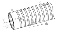
- FIG. 4 is a perspective view showing a part of the wire harness in the modified example.
- the wire harness of the present disclosure is (1) A wire harness including a core wire and an electric wire having an insulating coating that covers the outer periphery of the core wire over the entire circumference, and a coating layer that coats the outer peripheral surface of the insulating coating.
- the coating layer is coated on the outer peripheral surface of the insulating coating, it is possible to cover the outer peripheral surface of the insulating coating while suppressing an increase in the outer diameter of the wire harness. Therefore, the flexibility of the wire harness can be improved.
- the coating layer preferably coats the outer peripheral surface of the insulating coating over the entire circumference. According to the above aspect, the outer circumference of the insulating coating can be protected by the coating layer over the entire circumference.
- the coating layer preferably coats the outer peripheral surface of the insulating coating from one end to the other end in the longitudinal direction of the insulating coating. According to the above aspect, the coating layer can protect the outer peripheral surface of the insulating coating over the entire longitudinal direction.
- the coating layer preferably has a plurality of recesses that open on the outer peripheral surface of the coating layer. According to the above aspect, the flexibility of the wire harness is further improved by the plurality of recesses provided in the coating layer.
- the coating layer preferably has conductivity. According to the above aspect, the electromagnetic noise radiated from the electric wire can be blocked by the coating layer. Therefore, the wire harness does not need to be provided with a separate shield member.
- the wire harness 20 shown in FIG. 1 electrically connects two electric devices 11.
- the wire harness 20 of the present embodiment electrically connects the inverter 12 installed at the front of the vehicle 10 such as a hybrid vehicle or an electric vehicle and the battery 13 installed at the rear of the vehicle 10 with respect to the inverter 12. ..
- the inverter 12 is connected to a motor (not shown) for driving wheels, which is a power source for traveling the vehicle.
- the inverter 12 generates AC power from the DC power of the battery 13 and supplies the generated AC power to the motor.
- the battery 13 is, for example, a battery capable of supplying a voltage of one hundred and several tens to several hundreds of volts.
- the wire harness 20 is arranged so as to pass under the floor of the vehicle 10, for example.
- the wire harness 20 is arranged while being bent according to the shape of the space for arranging the wire harness 20.
- the portion of the wire harness 20 that passes under the floor of the vehicle 10 is covered with an under panel 14 that covers the lower part of the vehicle 10.
- the wire harness 20 includes an electric wire 21 and a coating layer 22 that coats the outer peripheral surface of the electric wire 21.
- One end of the electric wire 21 is connected to the inverter 12 via a connector 23 provided at one end of the electric wire 21.
- the other end of the electric wire 21 is connected to the battery 13 via a connector 24 provided at the other end of the electric wire 21.
- the electric wire 21 is, for example, a high-voltage electric wire that can handle high voltage and large current.
- FIG. 3 is a cross-sectional view of the wire harness 20 cut along the cross-sectional indicator line 3-3 shown in FIG.
- the core wire 31 is composed of one conductor. That is, the electric wire 21 of the present embodiment is a single wire in which the core wire 31 is composed of one conductor.
- the core wire 31 of the present embodiment has a circular cross-sectional shape orthogonal to the longitudinal direction.
- the longitudinal direction of the core wire 31 corresponds to the left-right direction in FIG. 2 and the vertical direction of the paper surface in FIG.
- a metal having excellent conductivity such as copper, a copper alloy, aluminum, and an aluminum alloy can be used.
- the insulating coating 32 covers the outer peripheral surface of the core wire 31 over the entire circumference. That is, the insulating coating 32 covers the outer peripheral surface of the core wire 31 over the entire circumference in the circumferential direction around the central axis L1 of the electric wire 21.
- the central axis L1 of the electric wire 21 extends from the center of the electric wire 21 in the direction perpendicular to the paper surface in FIG. Further, the insulating coating 32 covers the outer peripheral surface of the core wire 31 from one end to the other end in the longitudinal direction of the core wire 31. At both ends of the electric wire 21, the insulating coating 32 may be removed to expose the core wire 31 in order to electrically connect the core wire 31 to terminals (not shown) provided on the connectors 23 and 24.
- the insulating coating 32 is made of an insulating resin material. As the material of the insulating coating 32, for example, it is preferable to use a cross-linked polyethylene-based resin material.
- the coating layer 22 coats the outer peripheral surface of the insulating coating 32.
- the coating layer 22 has a film shape that covers the outer peripheral surface of the insulating coating 32.
- the coating layer 22 of the present embodiment coats the outer peripheral surface of the insulating coating 32 over the entire circumference. That is, the coating layer 22 covers the outer peripheral surface of the insulating coating 32 over the entire circumference in the circumferential direction around the central axis L1 of the electric wire 21. Further, the coating layer 22 coats the outer peripheral surface of the insulating coating 32 from one end to the other end in the longitudinal direction of the insulating coating 32.
- the longitudinal direction of the insulating coating 32 is the same as the longitudinal direction of the core wire 31.
- the coating layer 22 continuously coats the outer peripheral surface of the insulating coating 32 from the connector 23 provided at one end of the electric wire 21 to the connector 24 provided at the other end of the electric wire 21, the same applies. It is assumed that the coating layer 22 coats the outer peripheral surface of the insulating coating 32 from one end to the other end in the longitudinal direction of the insulating coating 32. In the present embodiment, on the outer peripheral surface of the insulating coating 32, the portion between the connector 23 and the connector 24 is entirely covered by the coating layer 22.
- the coating layer 22 is made of a resin material that can be coated on the outer peripheral surface of the insulating coating 32.
- the coating layer 22 is preferably made of a material having flexibility that can be deformed with the deformation of the electric wire 21 when the wire harness 20 is bent. That is, it is preferable that the coating layer 22 does not prevent the electric wire 21 from being bent by being deformed following the deformation of the electric wire 21. Further, the coating layer 22 preferably has a strength capable of protecting the electric wire 21 from foreign substances such as stepping stones that have entered the inside of the vehicle 10 through the gap of the under panel 14, that is, a traumatic resistance. As the material of the coating layer 22, for example, a polyolefin-based resin material is preferably used.
- the coating layer 22 is formed on the outer peripheral surface of the insulating coating 32 by extrusion molding.
- the portion of the vehicle 10 passing under the floor is prevented from colliding with foreign matter such as stepping stones by the under panel 14. Then, when a foreign substance such as a stepping stone invades through the gap of the under panel 14, the coating layer 22 protects the electric wire 21 from the foreign substance.
- the wire harness 20 includes a core wire 31 and an electric wire 21 having an insulating coating 32 that covers the outer periphery of the core wire 31 over the entire circumference, and a coating layer 22 that coats the outer peripheral surface of the insulating coating 32.
- the coating layer 22 is coated on the outer peripheral surface of the insulating coating 32, the outer peripheral surface of the insulating coating 32 can be covered while suppressing an increase in the outer diameter of the wire harness 20. it can. Therefore, the flexibility of the wire harness 20 can be improved. As a result, the wire harness 20 can be easily arranged on the vehicle 10.
- the exterior member plays a role of protecting the electric wire from an external impact due to contact with a foreign substance or the like
- the exterior member has high rigidity because it has enough strength to withstand the impact. May be formed of material. In this case, the wire harness is less likely to be bent.
- the coating layer 22 coats the outer peripheral surface of the insulating coating 32, the rigidity can be lowered as compared with the conventional high-rigidity exterior member. Therefore, the wire harness 20 provided with the coating layer 22 has improved flexibility as compared with the conventional wire harness provided with a highly rigid exterior member.
- the coating layer 22 coats the outer peripheral surface of the insulating coating 32 over the entire circumference. Therefore, the outer circumference of the insulating coating 32 can be protected by the coating layer 22 over the entire circumference.
- the coating layer 22 coats the outer peripheral surface of the insulating coating 32 from one end to the other end in the longitudinal direction of the insulating coating 32. Therefore, the coating layer 22 can protect the outer peripheral surface of the insulating coating 32 over the entire longitudinal direction.
- the outer diameter of the wire harness 20 provided with the coating layer 22 can be made smaller than that of the conventional wire harness provided with the tubular exterior member into which the electric wire is inserted. That is, since the gap between the exterior member and the electric wire that occurs in the conventional wire harness can be eliminated, the outer diameter of the wire harness 20 can be made smaller than the outer diameter of the conventional wire harness. Therefore, the wire harness 20 can be arranged in a narrower space. Further, since there is no gap between the electric wire 21 and the coating layer 22, the heat dissipation of the wire harness 20 can be improved.
- the coating layer 22 coats the outer peripheral surface of the insulating coating 32, it can be easily formed regardless of the shape of the electric wire 21.
- the coating layer 22 coats the outer peripheral surface of the insulating coating 32, it is integrally provided on the outer peripheral surface of the insulating coating 32. Therefore, the number of parts can be reduced as compared with the conventional wire harness in which the exterior member and the electric wire are separately provided. Further, since it is not necessary to perform a complicated process of inserting the electric wire into the tubular exterior member formed separately from the electric wire, the wire harness 20 can be easily manufactured.
- This embodiment can be modified and implemented as follows.
- the present embodiment and the following modified examples can be implemented in combination with each other within a technically consistent range.
- the coating layer 22 may have conductivity. In this way, the electromagnetic noise radiated from the electric wire 21 can be blocked by the coating layer 22. Therefore, the wire harness 20 does not need to be provided with a separate shield member.
- the coating layer 22 is configured not to have a recess that opens on the outer peripheral surface of the coating layer 22.
- the coating layer 22 may have a plurality of recesses that open on the outer peripheral surface of the coating layer 22.
- the coating layer 22 provided in the wire harness 20A shown in FIG. 4 has a plurality of recesses 41 that open on the outer peripheral surface of the coating layer 22.
- each recess 41 has a groove shape that is inclined with respect to the central axis L1 of the electric wire 21, that is, extends so as not to be parallel to the central axis L1 of the electric wire 21.
- each recess 41 has an annular shape extending along the circumferential direction around the central axis L1 of the electric wire 21.
- the plurality of recesses 41 are arranged at intervals in the longitudinal direction of the electric wire 21. Further, in the example shown in FIG. 4, the depth of each recess 41 is shallower than the thickness of the coating layer 22.
- the recess 41 may be provided in a part of the wire harness 20A including the bent portion, or may be provided as a whole.
- the flexibility of the wire harness is further improved by the plurality of recesses 41 provided in the coating layer 22.
- the recess 41 forms an annular shape extending along the circumferential direction around the central axis L1 of the electric wire 21, the wire harness 20A can be easily bent in any direction.
- the shape of the recess 41 included in the coating layer 22 is not limited to the shape shown in FIG.
- the recess 41 may have an arcuate shape extending along the circumferential direction around the central axis L1 of the electric wire 21, a groove shape inclined with respect to the central axis L1 of the electric wire 21, and the like.
- the recess 41 may be a hemispherical recess or the like that does not form a groove.
- the recess 41 may have a slit shape or a hole shape penetrating the coating layer 22.
- the coating layer 22 coats the outer peripheral surface of the insulating coating 32 from one end to the other end in the longitudinal direction of the insulating coating 32.
- the coating layer 22 may partially coat the outer peripheral surface of the insulating coating 32 in the longitudinal direction of the insulating coating 32.
- the coating layer 22 coats the outer peripheral surface of the insulating coating 32 over the entire circumference.
- the coating layer 22 may partially coat the outer peripheral surface of the insulating coating 32 in the circumferential direction around the central axis L1 of the electric wire 21.
- the coating layer 22 is not limited to extrusion molding, and can be formed by a known method capable of coating the outer peripheral surface of the insulating coating 32 with the coating layer 22.
- the resin material forming the coating layer 22 is coated on the outer peripheral surface of the insulating coating 32 by application such as brush coating, dipping, or spray coating to form the coating layer 22 that coats the outer peripheral surface of the insulating coating 32. You may.
- the coating layer 22 is not limited to the polyolefin-based resin material, and may be made of a resin material that can be coated on the outer peripheral surface of the insulating coating 32.
- the insulating coating 32 is not limited to the cross-linked polyethylene-based resin material, and may be made of an insulating resin material.
- the resin material of the coating layer 22 and the resin material of the insulating coating 32 are coated layers when the wire harness 20 is at a high temperature or when a liquid such as chemicals, oil, or salt water adheres to the wire harness 20. It is preferable that the resin material of 22 and the resin material of the insulating coating 32 are materials that do not deteriorate due to a chemical reaction. Further, the resin material of the coating layer 22 is preferably a material having high wear resistance.
- the shape of the core wire 31 is not limited to the shape of the above embodiment.
- the core wire 31 may have various shapes such as a polygonal shape, an elliptical shape, and a flat rectangular shape in a cross section orthogonal to the longitudinal direction of the concentric wire 31. ..
- the core wire 31 may be a stranded wire composed of a plurality of conductive metal wires.
- the wire harness 20 is arranged so as to pass under the floor of the vehicle 10.
- the place where the wire harness 20 is arranged is not limited to this, and may be appropriately changed depending on the arrangement position and the like of the two electric devices 11 to which the wire harness 20 is connected.
- the inverter 12 and the battery 13 are taken as an example of the electric device 11 connected by the wire harness 20.
- the electric device 11 connected by the wire harness 20 is not limited to this, and may be any electric device 11 mounted on the vehicle 10.
Landscapes
- Engineering & Computer Science (AREA)
- Insulated Conductors (AREA)
- Architecture (AREA)
- Civil Engineering (AREA)
- Structural Engineering (AREA)
- Mechanical Engineering (AREA)
- Details Of Indoor Wiring (AREA)
Abstract
本開示の課題は、屈曲性が向上されたワイヤハーネスを提供することにある。ワイヤハーネス(20)は、芯線(31)及び芯線(31)の外周を全周にわたって被覆する絶縁被覆(32)を有する電線(21)と、絶縁被覆(32)の外周面をコーティングするコーティング層(22)とを備えている。
Description
本開示は、ワイヤハーネスに関するものである。
従来、自動車等に搭載される電気機器間を電気的に接続するためのワイヤハーネスとしては、芯線及び芯線の外周を被覆する絶縁被覆を有する電線と、電線の外周を覆う外装部材とを備えたものが知られている。例えば特許文献1に記載されたワイヤハーネスは、電線が挿入される筒状の外装部材を備えている。
一般的に、ワイヤハーネスは、車両に搭載される際には屈曲されて配策されることが多いため、ワイヤハーネスの配策を容易に行うべくワイヤハーネスの屈曲性を向上させることが望まれている。しかしながら、特許文献1に記載されたワイヤハーネスは、筒状の外装部材に電線が挿入された構成であるため、ワイヤハーネスの外径が大きくなりやすい。そのため、当該ワイヤハーネスは、屈曲されやすいとは言い難かった。
本開示の目的は、屈曲性が向上されたワイヤハーネスを提供することにある。
本開示のワイヤハーネスは、芯線及び前記芯線の外周を全周にわたって被覆する絶縁被覆を有する電線と、前記絶縁被覆の外周面をコーティングするコーティング層とを備えたワイヤハーネスである。
本開示のワイヤハーネスによれば、屈曲性を向上できる。
[本開示の実施形態の説明]
最初に本開示の実施態様を列記して説明する。
本開示のワイヤハーネスは、
(1)芯線及び前記芯線の外周を全周にわたって被覆する絶縁被覆を有する電線と、前記絶縁被覆の外周面をコーティングするコーティング層とを備えたワイヤハーネスである。
最初に本開示の実施態様を列記して説明する。
本開示のワイヤハーネスは、
(1)芯線及び前記芯線の外周を全周にわたって被覆する絶縁被覆を有する電線と、前記絶縁被覆の外周面をコーティングするコーティング層とを備えたワイヤハーネスである。
上記態様によれば、コーティング層は、絶縁被膜の外周面にコーティングされたものであるため、ワイヤハーネスの外径が大きくなることを抑制しつつ絶縁被覆の外周面を覆うことができる。従って、ワイヤハーネスの屈曲性を向上できる。
(2)前記コーティング層は、前記絶縁被覆の外周面を全周にわたってコーティングしていることが好ましい。
上記態様によれば、絶縁被覆の外周をコーティング層によって全周にわたって保護することが可能になる。
上記態様によれば、絶縁被覆の外周をコーティング層によって全周にわたって保護することが可能になる。
(3)前記コーティング層は、前記絶縁被覆の外周面を前記絶縁被覆の長手方向の一端部から他端部にわたってコーティングしていることが好ましい。
上記態様によれば、コーティング層によって絶縁被覆の外周面を長手方向の全体にわたって保護できる。
上記態様によれば、コーティング層によって絶縁被覆の外周面を長手方向の全体にわたって保護できる。
(4)前記コーティング層は、前記コーティング層の外周面に開口する複数の凹部を有することが好ましい。
上記態様によれば、コーティング層に設けられた複数の凹部によって、ワイヤハーネスの屈曲性がより向上される。
上記態様によれば、コーティング層に設けられた複数の凹部によって、ワイヤハーネスの屈曲性がより向上される。
(5)前記コーティング層は、導電性を有することが好ましい。
上記態様によれば、電線から放射される電磁ノイズをコーティング層によって遮断可能になる。従って、ワイヤハーネスは、別途シールド部材を備えなくてもよくなる。
上記態様によれば、電線から放射される電磁ノイズをコーティング層によって遮断可能になる。従って、ワイヤハーネスは、別途シールド部材を備えなくてもよくなる。
[本開示の実施形態の詳細]
本開示のワイヤハーネスの具体例を、以下に図面を参照しつつ説明する。なお、本発明はこれらの例示に限定されるものではなく、特許請求の範囲によって示され、特許請求の範囲と均等の意味及び範囲内でのすべての変更が含まれることが意図される。また、添付図面は、理解を容易にするために構成要素を拡大して示している場合がある。添付図面において、構成要素の寸法比率は、実際のものと、または別の図中のものと異なる場合がある。
本開示のワイヤハーネスの具体例を、以下に図面を参照しつつ説明する。なお、本発明はこれらの例示に限定されるものではなく、特許請求の範囲によって示され、特許請求の範囲と均等の意味及び範囲内でのすべての変更が含まれることが意図される。また、添付図面は、理解を容易にするために構成要素を拡大して示している場合がある。添付図面において、構成要素の寸法比率は、実際のものと、または別の図中のものと異なる場合がある。
以下、ワイヤハーネスの一実施形態について説明する。
図1に示すワイヤハーネス20は、2個の電気機器11を電気的に接続する。本実施形態のワイヤハーネス20は、ハイブリッド車や電気自動車等の車両10の前部に設置されたインバータ12と、インバータ12よりも車両10の後方に設置されたバッテリ13とを電気的に接続する。インバータ12は、車両走行の動力源となる車輪駆動用の図示しないモータと接続される。インバータ12は、バッテリ13の直流電力から交流電力を生成し、生成した交流電力をモータに供給する。バッテリ13は、例えば百数十~数百ボルトの電圧を供給可能なバッテリである。
図1に示すワイヤハーネス20は、2個の電気機器11を電気的に接続する。本実施形態のワイヤハーネス20は、ハイブリッド車や電気自動車等の車両10の前部に設置されたインバータ12と、インバータ12よりも車両10の後方に設置されたバッテリ13とを電気的に接続する。インバータ12は、車両走行の動力源となる車輪駆動用の図示しないモータと接続される。インバータ12は、バッテリ13の直流電力から交流電力を生成し、生成した交流電力をモータに供給する。バッテリ13は、例えば百数十~数百ボルトの電圧を供給可能なバッテリである。
ワイヤハーネス20は、例えば、車両10の床下等を通るように配策される。ワイヤハーネス20は、同ワイヤハーネス20を配策するためのスペースの形状に応じて、屈曲されながら配策されている。ワイヤハーネス20において車両10の床下を通る部分は、車両10の下部を覆うアンダーパネル14にて覆われている。
図1及び図2に示すように、ワイヤハーネス20は、電線21と、電線21の外周面をコーティングするコーティング層22とを備えている。電線21の一端部は、同電線21の一端部に設けられたコネクタ23を介してインバータ12と接続されている。電線21の他端部は、同電線21の他端部に設けられたコネクタ24を介してバッテリ13と接続されている。電線21は、例えば、高電圧・大電流に対応可能な高圧電線である。
[電線の構成]
図2及び図3に示すように、電線21は、芯線31及び芯線31の外周を全周に亘って被覆する絶縁被覆32を有する。因みに、図3は、図2に示す断面指示線3-3で切ったワイヤハーネス20の断面図である。
図2及び図3に示すように、電線21は、芯線31及び芯線31の外周を全周に亘って被覆する絶縁被覆32を有する。因みに、図3は、図2に示す断面指示線3-3で切ったワイヤハーネス20の断面図である。
芯線31は、1本の導体よりなる。即ち、本実施形態の電線21は、芯線31が1本の導体よりなる単線である。本実施形態の芯線31は、長手方向と直交する断面形状が円形状をなしている。なお、芯線31の長手方向は、図2においては左右方向、図3においては紙面垂直方向に該当する。芯線31の材料としては、例えば、銅、銅合金、アルミニウム、アルミニウム合金などの導電性に優れた金属を用いることができる。
絶縁被覆32は、芯線31の外周面を全周にわたって被覆している。即ち、絶縁被覆32は、電線21の中心軸線L1回りの周方向の全周にわたって芯線31の外周面を被覆している。なお、電線21の中心軸線L1は、図3においては電線21の中心を紙面垂直方向に延びている。また、絶縁被覆32は、芯線31の長手方向の一端部から他端部にわたって芯線31の外周面を被覆している。なお、電線21の両端部においては、コネクタ23,24に備えられる図示しない端子に芯線31を電気的に接続するために、絶縁被覆32が除去されて芯線31が露出していることがある。絶縁被覆32は、絶縁性の樹脂材料よりなる。絶縁被覆32の材料としては、例えば、架橋ポリエチレン系の樹脂材料を用いることが好ましい。
[コーティング層の構成]
コーティング層22は、絶縁被覆32の外周面をコーティングしている。コーティング層22は、絶縁被覆32の外周面を覆う膜状をなしている。本実施形態のコーティング層22は、絶縁被覆32の外周面を全周にわたってコーティングしている。即ち、コーティング層22は、電線21の中心軸線L1回りの周方向の全周にわたって絶縁被覆32の外周面を覆っている。また、コーティング層22は、絶縁被覆32の外周面を同絶縁被覆32の長手方向の一端部から他端部にわたってコーティングしている。絶縁被覆32の長手方向は、芯線31の長手方向と同じ方向である。なお、電線21の一端部に設けられたコネクタ23から、同電線21の他端部に設けられたコネクタ24まで連続して絶縁被覆32の外周面をコーティング層22がコーティングしていれば、同コーティング層22は、絶縁被覆32の外周面を同絶縁被覆32の長手方向の一端部から他端部にわたってコーティングしているものとする。本実施形態では、絶縁被覆32の外周面において、コネクタ23とコネクタ24との間の部分は、コーティング層22によって全体的に覆われている。
コーティング層22は、絶縁被覆32の外周面をコーティングしている。コーティング層22は、絶縁被覆32の外周面を覆う膜状をなしている。本実施形態のコーティング層22は、絶縁被覆32の外周面を全周にわたってコーティングしている。即ち、コーティング層22は、電線21の中心軸線L1回りの周方向の全周にわたって絶縁被覆32の外周面を覆っている。また、コーティング層22は、絶縁被覆32の外周面を同絶縁被覆32の長手方向の一端部から他端部にわたってコーティングしている。絶縁被覆32の長手方向は、芯線31の長手方向と同じ方向である。なお、電線21の一端部に設けられたコネクタ23から、同電線21の他端部に設けられたコネクタ24まで連続して絶縁被覆32の外周面をコーティング層22がコーティングしていれば、同コーティング層22は、絶縁被覆32の外周面を同絶縁被覆32の長手方向の一端部から他端部にわたってコーティングしているものとする。本実施形態では、絶縁被覆32の外周面において、コネクタ23とコネクタ24との間の部分は、コーティング層22によって全体的に覆われている。
コーティング層22は、絶縁被覆32の外周面にコーティング可能な樹脂材料よりなる。コーティング層22は、ワイヤハーネス20を屈曲させた場合に、電線21の変形に伴って変形可能な柔軟性を有する材料よりなることが好ましい。即ち、コーティング層22は、電線21の変形に追従して変形することにより、電線21が屈曲されることを妨げないものであることが好ましい。また、コーティング層22は、アンダーパネル14の隙間から車両10の内部側に侵入した飛び石等の異物から電線21を保護可能な強度、即ち耐外傷性を有することが好ましい。コーティング層22の材料としては、例えば、ポリオレフィン系の樹脂材料を用いることが好ましい。コーティング層22は、押出成形により絶縁被覆32の外周面に形成される。
ワイヤハーネス20において車両10の床下を通る部分は、アンダーパネル14によって飛び石等の異物が衝突することが抑制されている。そして、コーティング層22は、アンダーパネル14の隙間から飛び石等の異物が侵入した場合に、当該異物から電線21を保護する。
本実施形態の作用及び効果について説明する。
(1)ワイヤハーネス20は、芯線31及び芯線31の外周を全周にわたって被覆する絶縁被覆32を有する電線21と、絶縁被覆32の外周面をコーティングするコーティング層22とを備えている。
(1)ワイヤハーネス20は、芯線31及び芯線31の外周を全周にわたって被覆する絶縁被覆32を有する電線21と、絶縁被覆32の外周面をコーティングするコーティング層22とを備えている。
上記態様によれば、コーティング層22は、絶縁被覆32の外周面にコーティングされたものであるため、ワイヤハーネス20の外径が大きくなることを抑制しつつ絶縁被覆32の外周面を覆うことができる。従って、ワイヤハーネス20の屈曲性を向上できる。その結果、ワイヤハーネス20の車両10への配策を容易に行うことができる。
また、従来のワイヤハーネスにおいて、異物等の接触による外部の衝撃から電線を保護する役割を外装部材が担う場合には、外装部材は、当該衝撃に耐え得るだけの強度を有するために高剛性の材料で形成されることがある。この場合には、ワイヤハーネスは、より屈曲され難いものとなる。これに対し、コーティング層22は、絶縁被覆32の外周面をコーティングするものであるため、従来の高剛性な外装部材に比べて剛性を低くできる。従って、コーティング層22を備えた当該ワイヤハーネス20は、従来の高剛性な外装部材を備えたワイヤハーネスに比べて屈曲性が向上される。
(2)コーティング層22は、絶縁被覆32の外周面を全周にわたってコーティングしている。このため、絶縁被覆32の外周をコーティング層22によって全周にわたって保護できる。
(3)コーティング層22は、絶縁被覆32の外周面を絶縁被覆32の長手方向の一端部から他端部にわたってコーティングしている。このため、コーティング層22によって絶縁被覆32の外周面を長手方向の全体にわたって保護できる。
(4)電線が挿入される筒状の外装部材を備えた従来のワイヤハーネスに比べて、コーティング層22を備えたワイヤハーネス20は、外径を小さくできる。即ち、従来のワイヤハーネスにおいて生じる外装部材と電線との間の隙間をなくすことができるため、ワイヤハーネス20の外径を従来のワイヤハーネスの外径に比べて小さくできる。従って、より狭いスペースにワイヤハーネス20を配策可能になる。また、電線21とコーティング層22との間に隙間がないことから、ワイヤハーネス20における放熱性を向上できる。
(5)コーティング層22は、絶縁被覆32の外周面をコーティングするものであるため、電線21の形状にかかわらず容易に形成することができる。
(6)コーティング層22は、絶縁被覆32の外周面をコーティングするものであるため、絶縁被覆32の外周面に一体的に設けられている。従って、外装部材と電線とが別体に設けられた従来のワイヤハーネスに比べて、部品点数を減少させることができる。また、電線と別体で形成された筒状の外装部材に電線を挿入する煩雑な工程を行わなくてもよいため、ワイヤハーネス20を容易に製造できる。
(6)コーティング層22は、絶縁被覆32の外周面をコーティングするものであるため、絶縁被覆32の外周面に一体的に設けられている。従って、外装部材と電線とが別体に設けられた従来のワイヤハーネスに比べて、部品点数を減少させることができる。また、電線と別体で形成された筒状の外装部材に電線を挿入する煩雑な工程を行わなくてもよいため、ワイヤハーネス20を容易に製造できる。
[他の実施形態]
本実施形態は、以下のように変更して実施することができる。本実施形態及び以下の変更例は、技術的に矛盾しない範囲で互いに組み合わせて実施することができる。
本実施形態は、以下のように変更して実施することができる。本実施形態及び以下の変更例は、技術的に矛盾しない範囲で互いに組み合わせて実施することができる。
・コーティング層22は、導電性を有するものであってもよい。このようにすると、電線21から放射される電磁ノイズをコーティング層22によって遮断可能になる。従って、ワイヤハーネス20は、別途シールド部材を備えなくてもよくなる。
・上記実施形態では、コーティング層22は、コーティング層22の外周面に開口する凹部を備えない構成とした。しかしながら、コーティング層22は、コーティング層22の外周面に開口する複数の凹部を有するものであってもよい。
例えば、図4に示すワイヤハーネス20Aに備えられたコーティング層22は、コーティング層22の外周面に開口する複数の凹部41を有する。なお、図4では、上記実施形態と同じ構成部材又は対応する構成部材については、同じ符号を付している。図4に示す例では、各凹部41は、電線21の中心軸線L1に対して傾斜、即ち、電線21の中心軸線L1とは平行をなさないように延びる溝状をなしている。更に、各凹部41は、電線21の中心軸線L1回りの周方向に沿って延びる環状をなしている。複数の凹部41は、電線21の長手方向に間隔を空けて並んでいる。また、図4に示す例では、各凹部41の深さは、コーティング層22の厚さよりも浅い。凹部41は、ワイヤハーネス20Aにおいて屈曲される部分を含む一部分に設けられてもよいし、全体的に設けられてもよい。
このようにすると、コーティング層22に設けられた複数の凹部41によって、ワイヤハーネスの屈曲性がより向上される。その結果、ワイヤハーネス20Aの車両10への配策をより容易に行うことができる。また、凹部41が電線21の中心軸線L1回りの周方向に沿って延びる環状をなしているため、どの方向へもワイヤハーネス20Aを屈曲しやすくなる。
なお、コーティング層22が備える凹部41の形状は、図4に示した形状に限らない。例えば、凹部41は、電線21の中心軸線L1回りの周方向に沿って延びる弧状をなす溝状、電線21の中心軸線L1に対して傾斜した溝状等であってもよい。また例えば、凹部41は、半球状の凹部等、溝状をなさないものであってもよい。また、凹部41は、コーティング層22を貫通するスリット状や孔状をなすものであってもよい。
・上記実施形態では、コーティング層22は、絶縁被覆32の外周面を同絶縁被覆32の長手方向の一端部から他端部にわたってコーティングしている。しかしながら、コーティング層22は、絶縁被覆32の長手方向において、絶縁被覆32の外周面を部分的にコーティングするものであってもよい。
・上記実施形態では、コーティング層22は、絶縁被覆32の外周面を全周にわたってコーティングしている。しかしながら、コーティング層22は、電線21の中心軸線L1回りの周方向において、絶縁被覆32の外周面を部分的にコーティングするものであってもよい。
・コーティング層22は、押出成形に限らず、絶縁被覆32の外周面をコーティング層22にてコーティングすることが可能な公知の方法で形成することができる。例えば、コーティング層22を形成する樹脂材料を、刷毛塗りなどの塗布、浸漬、スプレー塗装などにより絶縁被覆32の外周面に塗装することにより、絶縁被覆32の外周面をコーティングするコーティング層22を形成してもよい。
・コーティング層22は、ポリオレフィン系の樹脂材料に限らず、絶縁被覆32の外周面にコーティング可能な樹脂材料よりなるものであればよい。また、絶縁被覆32は、架橋ポリエチレン系の樹脂材料に限らず、絶縁性の樹脂材料よりなるものであればよい。ただし、コーティング層22の樹脂材料及び絶縁被覆32の樹脂材料は、ワイヤハーネス20が高温下にある場合において、または、ワイヤハーネス20に薬品、オイル、塩水などの液体が付着した場合において、コーティング層22の樹脂材料と絶縁被覆32の樹脂材料とが化学的な反応により劣化しない材料であることが好ましい。更に、コーティング層22の樹脂材料は、耐摩耗性が高い材料であることが好ましい。
・芯線31の形状は、上記実施形態の形状に限らない。電線21が単線である場合には、芯線31は、同芯線31の長手方向と直交する断面の形状が多角形状、楕円形状、扁平な長方形状などの様々な形状をなすものであってもよい。また、芯線31は、導電性を有する複数の金属線からなる撚線であってもよい。
・上記実施形態では、ワイヤハーネス20は、車両10の床下等を通るように配策されている。しかしながら、車両10において、ワイヤハーネス20が配策される場所は、これに限らず、ワイヤハーネス20が接続する2つの電気機器11の配置位置等に応じて適宜変更してもよい。
・上記実施形態では、ワイヤハーネス20によって接続される電気機器11としてインバータ12及びバッテリ13を例に挙げた。しかしながら、ワイヤハーネス20によって接続される電気機器11はこれに限らず、車両10に搭載される電気機器11であればよい。
10 車両
11 電気機器
12 インバータ
13 バッテリ
14 アンダーパネル
20 ワイヤハーネス
20A ワイヤハーネス
21 電線
22 コーティング層
23 コネクタ
24 コネクタ
31 芯線
32 絶縁被覆
41 凹部
L1 中心軸線
11 電気機器
12 インバータ
13 バッテリ
14 アンダーパネル
20 ワイヤハーネス
20A ワイヤハーネス
21 電線
22 コーティング層
23 コネクタ
24 コネクタ
31 芯線
32 絶縁被覆
41 凹部
L1 中心軸線
Claims (5)
- 芯線及び前記芯線の外周を全周にわたって被覆する絶縁被覆を有する電線と、
前記絶縁被覆の外周面をコーティングするコーティング層と
を備えたワイヤハーネス。 - 前記コーティング層は、前記絶縁被覆の外周面を全周にわたってコーティングしている請求項1に記載のワイヤハーネス。
- 前記コーティング層は、前記絶縁被覆の外周面を前記絶縁被覆の長手方向の一端部から他端部にわたってコーティングしている請求項1又は請求項2に記載のワイヤハーネス。
- 前記コーティング層は、前記コーティング層の外周面に開口する複数の凹部を有する請求項1から請求項3の何れか1項に記載のワイヤハーネス。
- 前記コーティング層は、導電性を有する請求項1から請求項4の何れか1項に記載のワイヤハーネス。
Applications Claiming Priority (2)
| Application Number | Priority Date | Filing Date | Title |
|---|---|---|---|
| JP2019210703A JP2021082536A (ja) | 2019-11-21 | 2019-11-21 | ワイヤハーネス |
| JP2019-210703 | 2019-11-21 |
Publications (1)
| Publication Number | Publication Date |
|---|---|
| WO2021100568A1 true WO2021100568A1 (ja) | 2021-05-27 |
Family
ID=75965904
Family Applications (1)
| Application Number | Title | Priority Date | Filing Date |
|---|---|---|---|
| PCT/JP2020/042030 Ceased WO2021100568A1 (ja) | 2019-11-21 | 2020-11-11 | ワイヤハーネス |
Country Status (2)
| Country | Link |
|---|---|
| JP (1) | JP2021082536A (ja) |
| WO (1) | WO2021100568A1 (ja) |
Families Citing this family (1)
| Publication number | Priority date | Publication date | Assignee | Title |
|---|---|---|---|---|
| JP7810071B2 (ja) * | 2022-06-15 | 2026-02-03 | 住友電装株式会社 | ワイヤハーネス |
Citations (2)
| Publication number | Priority date | Publication date | Assignee | Title |
|---|---|---|---|---|
| JPH06176633A (ja) * | 1992-12-08 | 1994-06-24 | Sumitomo Wiring Syst Ltd | ワイヤーハーネスのシールド方法 |
| JP2015065783A (ja) * | 2013-09-26 | 2015-04-09 | 矢崎総業株式会社 | ワイヤハーネス |
-
2019
- 2019-11-21 JP JP2019210703A patent/JP2021082536A/ja active Pending
-
2020
- 2020-11-11 WO PCT/JP2020/042030 patent/WO2021100568A1/ja not_active Ceased
Patent Citations (2)
| Publication number | Priority date | Publication date | Assignee | Title |
|---|---|---|---|---|
| JPH06176633A (ja) * | 1992-12-08 | 1994-06-24 | Sumitomo Wiring Syst Ltd | ワイヤーハーネスのシールド方法 |
| JP2015065783A (ja) * | 2013-09-26 | 2015-04-09 | 矢崎総業株式会社 | ワイヤハーネス |
Also Published As
| Publication number | Publication date |
|---|---|
| JP2021082536A (ja) | 2021-05-27 |
Similar Documents
| Publication | Publication Date | Title |
|---|---|---|
| US9496071B2 (en) | Shield wire | |
| JP7359263B2 (ja) | 外装部材及びワイヤハーネス | |
| JP6812921B2 (ja) | 導電線及びワイヤハーネス | |
| CN112041944A (zh) | 导电路径及线束 | |
| JP7524673B2 (ja) | ワイヤハーネスユニット | |
| JP2018156991A (ja) | 電磁シールド部品及びワイヤハーネス | |
| JP2020166966A (ja) | ワイヤハーネス | |
| WO2020066587A1 (ja) | ワイヤハーネス | |
| JP6973341B2 (ja) | ワイヤハーネス | |
| US9672960B2 (en) | Exterior member and electric wire wiring structure | |
| WO2021100568A1 (ja) | ワイヤハーネス | |
| US11745674B2 (en) | Wire harness with exterior tube, first protective body and second protective body | |
| US11192509B2 (en) | Wire harness for dissipating heat generated by wires | |
| JP2018101510A (ja) | ワイヤハーネス | |
| EP2628222B1 (en) | Routing structure of a wiring harness | |
| US20220189655A1 (en) | Wire harness | |
| JP7794009B2 (ja) | ワイヤハーネス | |
| US12156393B2 (en) | Wire harness | |
| JP2019053958A (ja) | ワイヤハーネス | |
| WO2021251165A1 (ja) | ワイヤハーネスユニット | |
| JP7848929B2 (ja) | ワイヤハーネス | |
| JP7524674B2 (ja) | ワイヤハーネスユニット | |
| JP2021005448A (ja) | ワイヤハーネス | |
| JP2021103638A (ja) | ワイヤハーネス |
Legal Events
| Date | Code | Title | Description |
|---|---|---|---|
| 121 | Ep: the epo has been informed by wipo that ep was designated in this application |
Ref document number: 20888746 Country of ref document: EP Kind code of ref document: A1 |
|
| NENP | Non-entry into the national phase |
Ref country code: DE |
|
| 122 | Ep: pct application non-entry in european phase |
Ref document number: 20888746 Country of ref document: EP Kind code of ref document: A1 |