WO2021095592A1 - 摺動部品 - Google Patents
摺動部品 Download PDFInfo
- Publication number
- WO2021095592A1 WO2021095592A1 PCT/JP2020/041089 JP2020041089W WO2021095592A1 WO 2021095592 A1 WO2021095592 A1 WO 2021095592A1 JP 2020041089 W JP2020041089 W JP 2020041089W WO 2021095592 A1 WO2021095592 A1 WO 2021095592A1
- Authority
- WO
- WIPO (PCT)
- Prior art keywords
- graphite film
- sliding
- sealing ring
- base material
- sliding surface
- Prior art date
Links
- OKTJSMMVPCPJKN-UHFFFAOYSA-N Carbon Chemical compound [C] OKTJSMMVPCPJKN-UHFFFAOYSA-N 0.000 claims abstract description 141
- 229910002804 graphite Inorganic materials 0.000 claims abstract description 133
- 239000010439 graphite Substances 0.000 claims abstract description 133
- 239000000463 material Substances 0.000 claims abstract description 73
- 230000013011 mating Effects 0.000 claims description 10
- 239000000919 ceramic Substances 0.000 claims description 6
- 230000000694 effects Effects 0.000 abstract description 11
- 239000010408 film Substances 0.000 description 128
- 238000007789 sealing Methods 0.000 description 80
- HBMJWWWQQXIZIP-UHFFFAOYSA-N silicon carbide Chemical compound [Si+]#[C-] HBMJWWWQQXIZIP-UHFFFAOYSA-N 0.000 description 46
- 229910010271 silicon carbide Inorganic materials 0.000 description 44
- 230000003068 static effect Effects 0.000 description 37
- 239000012530 fluid Substances 0.000 description 11
- 229910052799 carbon Inorganic materials 0.000 description 9
- 238000005461 lubrication Methods 0.000 description 6
- 238000005087 graphitization Methods 0.000 description 5
- 229920005989 resin Polymers 0.000 description 5
- 239000011347 resin Substances 0.000 description 5
- 230000003746 surface roughness Effects 0.000 description 5
- 239000011248 coating agent Substances 0.000 description 4
- 238000000576 coating method Methods 0.000 description 4
- 239000000203 mixture Substances 0.000 description 4
- 238000001069 Raman spectroscopy Methods 0.000 description 3
- 238000005411 Van der Waals force Methods 0.000 description 3
- 230000015572 biosynthetic process Effects 0.000 description 3
- 239000013078 crystal Substances 0.000 description 3
- 238000010304 firing Methods 0.000 description 3
- 229910021397 glassy carbon Inorganic materials 0.000 description 3
- 239000007788 liquid Substances 0.000 description 3
- 238000010008 shearing Methods 0.000 description 3
- 238000004611 spectroscopical analysis Methods 0.000 description 3
- 229920001187 thermosetting polymer Polymers 0.000 description 3
- 239000010409 thin film Substances 0.000 description 3
- MCMNRKCIXSYSNV-UHFFFAOYSA-N Zirconium dioxide Chemical compound O=[Zr]=O MCMNRKCIXSYSNV-UHFFFAOYSA-N 0.000 description 2
- 230000002411 adverse Effects 0.000 description 2
- 125000004432 carbon atom Chemical group C* 0.000 description 2
- 239000007789 gas Substances 0.000 description 2
- 238000009499 grossing Methods 0.000 description 2
- 229910052751 metal Inorganic materials 0.000 description 2
- 239000002184 metal Substances 0.000 description 2
- 230000003287 optical effect Effects 0.000 description 2
- 239000007779 soft material Substances 0.000 description 2
- 239000000126 substance Substances 0.000 description 2
- ZOXJGFHDIHLPTG-UHFFFAOYSA-N Boron Chemical compound [B] ZOXJGFHDIHLPTG-UHFFFAOYSA-N 0.000 description 1
- 239000004641 Diallyl-phthalate Substances 0.000 description 1
- UFHFLCQGNIYNRP-UHFFFAOYSA-N Hydrogen Chemical compound [H][H] UFHFLCQGNIYNRP-UHFFFAOYSA-N 0.000 description 1
- 239000004640 Melamine resin Substances 0.000 description 1
- 229920000877 Melamine resin Polymers 0.000 description 1
- 229910052581 Si3N4 Inorganic materials 0.000 description 1
- 229920001807 Urea-formaldehyde Polymers 0.000 description 1
- 238000007792 addition Methods 0.000 description 1
- 239000000853 adhesive Substances 0.000 description 1
- 230000001070 adhesive effect Effects 0.000 description 1
- 229910052782 aluminium Inorganic materials 0.000 description 1
- XAGFODPZIPBFFR-UHFFFAOYSA-N aluminium Chemical compound [Al] XAGFODPZIPBFFR-UHFFFAOYSA-N 0.000 description 1
- PNEYBMLMFCGWSK-UHFFFAOYSA-N aluminium oxide Inorganic materials [O-2].[O-2].[O-2].[Al+3].[Al+3] PNEYBMLMFCGWSK-UHFFFAOYSA-N 0.000 description 1
- 229910003481 amorphous carbon Inorganic materials 0.000 description 1
- 238000004458 analytical method Methods 0.000 description 1
- QUDWYFHPNIMBFC-UHFFFAOYSA-N bis(prop-2-enyl) benzene-1,2-dicarboxylate Chemical compound C=CCOC(=O)C1=CC=CC=C1C(=O)OCC=C QUDWYFHPNIMBFC-UHFFFAOYSA-N 0.000 description 1
- 238000007664 blowing Methods 0.000 description 1
- 229910052796 boron Inorganic materials 0.000 description 1
- 150000001721 carbon Chemical group 0.000 description 1
- 239000003575 carbonaceous material Substances 0.000 description 1
- 239000002131 composite material Substances 0.000 description 1
- 238000012790 confirmation Methods 0.000 description 1
- 238000005336 cracking Methods 0.000 description 1
- 238000001723 curing Methods 0.000 description 1
- 238000001035 drying Methods 0.000 description 1
- 239000003822 epoxy resin Substances 0.000 description 1
- 230000005284 excitation Effects 0.000 description 1
- 239000010419 fine particle Substances 0.000 description 1
- 239000007770 graphite material Substances 0.000 description 1
- 238000013007 heat curing Methods 0.000 description 1
- 239000001257 hydrogen Substances 0.000 description 1
- 229910052739 hydrogen Inorganic materials 0.000 description 1
- 230000001050 lubricating effect Effects 0.000 description 1
- 239000007769 metal material Substances 0.000 description 1
- 239000003960 organic solvent Substances 0.000 description 1
- 239000002245 particle Substances 0.000 description 1
- 230000002093 peripheral effect Effects 0.000 description 1
- 239000005011 phenolic resin Substances 0.000 description 1
- 229920000647 polyepoxide Polymers 0.000 description 1
- 229920001721 polyimide Polymers 0.000 description 1
- 239000009719 polyimide resin Substances 0.000 description 1
- 229920005749 polyurethane resin Polymers 0.000 description 1
- 239000002243 precursor Substances 0.000 description 1
- 230000000717 retained effect Effects 0.000 description 1
- HQVNEWCFYHHQES-UHFFFAOYSA-N silicon nitride Chemical compound N12[Si]34N5[Si]62N3[Si]51N64 HQVNEWCFYHHQES-UHFFFAOYSA-N 0.000 description 1
- 229920002050 silicone resin Polymers 0.000 description 1
- 238000005245 sintering Methods 0.000 description 1
- 229910021384 soft carbon Inorganic materials 0.000 description 1
- 238000001228 spectrum Methods 0.000 description 1
- 239000000758 substrate Substances 0.000 description 1
- 238000002076 thermal analysis method Methods 0.000 description 1
- 229920006337 unsaturated polyester resin Polymers 0.000 description 1
- XLYOFNOQVPJJNP-UHFFFAOYSA-N water Substances O XLYOFNOQVPJJNP-UHFFFAOYSA-N 0.000 description 1
Images


Classifications
-
- F—MECHANICAL ENGINEERING; LIGHTING; HEATING; WEAPONS; BLASTING
- F16—ENGINEERING ELEMENTS AND UNITS; GENERAL MEASURES FOR PRODUCING AND MAINTAINING EFFECTIVE FUNCTIONING OF MACHINES OR INSTALLATIONS; THERMAL INSULATION IN GENERAL
- F16C—SHAFTS; FLEXIBLE SHAFTS; ELEMENTS OR CRANKSHAFT MECHANISMS; ROTARY BODIES OTHER THAN GEARING ELEMENTS; BEARINGS
- F16C33/00—Parts of bearings; Special methods for making bearings or parts thereof
- F16C33/02—Parts of sliding-contact bearings
- F16C33/04—Brasses; Bushes; Linings
- F16C33/24—Brasses; Bushes; Linings with different areas of the sliding surface consisting of different materials
-
- F—MECHANICAL ENGINEERING; LIGHTING; HEATING; WEAPONS; BLASTING
- F16—ENGINEERING ELEMENTS AND UNITS; GENERAL MEASURES FOR PRODUCING AND MAINTAINING EFFECTIVE FUNCTIONING OF MACHINES OR INSTALLATIONS; THERMAL INSULATION IN GENERAL
- F16J—PISTONS; CYLINDERS; SEALINGS
- F16J15/00—Sealings
- F16J15/16—Sealings between relatively-moving surfaces
- F16J15/34—Sealings between relatively-moving surfaces with slip-ring pressed against a more or less radial face on one member
- F16J15/3496—Sealings between relatively-moving surfaces with slip-ring pressed against a more or less radial face on one member use of special materials
-
- F—MECHANICAL ENGINEERING; LIGHTING; HEATING; WEAPONS; BLASTING
- F16—ENGINEERING ELEMENTS AND UNITS; GENERAL MEASURES FOR PRODUCING AND MAINTAINING EFFECTIVE FUNCTIONING OF MACHINES OR INSTALLATIONS; THERMAL INSULATION IN GENERAL
- F16C—SHAFTS; FLEXIBLE SHAFTS; ELEMENTS OR CRANKSHAFT MECHANISMS; ROTARY BODIES OTHER THAN GEARING ELEMENTS; BEARINGS
- F16C17/00—Sliding-contact bearings for exclusively rotary movement
-
- F—MECHANICAL ENGINEERING; LIGHTING; HEATING; WEAPONS; BLASTING
- F16—ENGINEERING ELEMENTS AND UNITS; GENERAL MEASURES FOR PRODUCING AND MAINTAINING EFFECTIVE FUNCTIONING OF MACHINES OR INSTALLATIONS; THERMAL INSULATION IN GENERAL
- F16C—SHAFTS; FLEXIBLE SHAFTS; ELEMENTS OR CRANKSHAFT MECHANISMS; ROTARY BODIES OTHER THAN GEARING ELEMENTS; BEARINGS
- F16C33/00—Parts of bearings; Special methods for making bearings or parts thereof
- F16C33/02—Parts of sliding-contact bearings
- F16C33/04—Brasses; Bushes; Linings
- F16C33/16—Sliding surface consisting mainly of graphite
-
- F—MECHANICAL ENGINEERING; LIGHTING; HEATING; WEAPONS; BLASTING
- F16—ENGINEERING ELEMENTS AND UNITS; GENERAL MEASURES FOR PRODUCING AND MAINTAINING EFFECTIVE FUNCTIONING OF MACHINES OR INSTALLATIONS; THERMAL INSULATION IN GENERAL
- F16C—SHAFTS; FLEXIBLE SHAFTS; ELEMENTS OR CRANKSHAFT MECHANISMS; ROTARY BODIES OTHER THAN GEARING ELEMENTS; BEARINGS
- F16C33/00—Parts of bearings; Special methods for making bearings or parts thereof
- F16C33/72—Sealings
- F16C33/74—Sealings of sliding-contact bearings
-
- F—MECHANICAL ENGINEERING; LIGHTING; HEATING; WEAPONS; BLASTING
- F16—ENGINEERING ELEMENTS AND UNITS; GENERAL MEASURES FOR PRODUCING AND MAINTAINING EFFECTIVE FUNCTIONING OF MACHINES OR INSTALLATIONS; THERMAL INSULATION IN GENERAL
- F16C—SHAFTS; FLEXIBLE SHAFTS; ELEMENTS OR CRANKSHAFT MECHANISMS; ROTARY BODIES OTHER THAN GEARING ELEMENTS; BEARINGS
- F16C35/00—Rigid support of bearing units; Housings, e.g. caps, covers
- F16C35/02—Rigid support of bearing units; Housings, e.g. caps, covers in the case of sliding-contact bearings
-
- F—MECHANICAL ENGINEERING; LIGHTING; HEATING; WEAPONS; BLASTING
- F16—ENGINEERING ELEMENTS AND UNITS; GENERAL MEASURES FOR PRODUCING AND MAINTAINING EFFECTIVE FUNCTIONING OF MACHINES OR INSTALLATIONS; THERMAL INSULATION IN GENERAL
- F16J—PISTONS; CYLINDERS; SEALINGS
- F16J15/00—Sealings
- F16J15/16—Sealings between relatively-moving surfaces
- F16J15/34—Sealings between relatively-moving surfaces with slip-ring pressed against a more or less radial face on one member
- F16J15/3464—Mounting of the seal
-
- F—MECHANICAL ENGINEERING; LIGHTING; HEATING; WEAPONS; BLASTING
- F16—ENGINEERING ELEMENTS AND UNITS; GENERAL MEASURES FOR PRODUCING AND MAINTAINING EFFECTIVE FUNCTIONING OF MACHINES OR INSTALLATIONS; THERMAL INSULATION IN GENERAL
- F16C—SHAFTS; FLEXIBLE SHAFTS; ELEMENTS OR CRANKSHAFT MECHANISMS; ROTARY BODIES OTHER THAN GEARING ELEMENTS; BEARINGS
- F16C2206/00—Materials with ceramics, cermets, hard carbon or similar non-metallic hard materials as main constituents
- F16C2206/40—Ceramics, e.g. carbides, nitrides, oxides, borides of a metal
- F16C2206/56—Ceramics, e.g. carbides, nitrides, oxides, borides of a metal based on ceramic carbides, e.g. silicon carbide (SiC)
-
- F—MECHANICAL ENGINEERING; LIGHTING; HEATING; WEAPONS; BLASTING
- F16—ENGINEERING ELEMENTS AND UNITS; GENERAL MEASURES FOR PRODUCING AND MAINTAINING EFFECTIVE FUNCTIONING OF MACHINES OR INSTALLATIONS; THERMAL INSULATION IN GENERAL
- F16C—SHAFTS; FLEXIBLE SHAFTS; ELEMENTS OR CRANKSHAFT MECHANISMS; ROTARY BODIES OTHER THAN GEARING ELEMENTS; BEARINGS
- F16C2240/00—Specified values or numerical ranges of parameters; Relations between them
- F16C2240/40—Linear dimensions, e.g. length, radius, thickness, gap
- F16C2240/54—Surface roughness
-
- F—MECHANICAL ENGINEERING; LIGHTING; HEATING; WEAPONS; BLASTING
- F16—ENGINEERING ELEMENTS AND UNITS; GENERAL MEASURES FOR PRODUCING AND MAINTAINING EFFECTIVE FUNCTIONING OF MACHINES OR INSTALLATIONS; THERMAL INSULATION IN GENERAL
- F16C—SHAFTS; FLEXIBLE SHAFTS; ELEMENTS OR CRANKSHAFT MECHANISMS; ROTARY BODIES OTHER THAN GEARING ELEMENTS; BEARINGS
- F16C2240/00—Specified values or numerical ranges of parameters; Relations between them
- F16C2240/40—Linear dimensions, e.g. length, radius, thickness, gap
- F16C2240/60—Thickness, e.g. thickness of coatings
Definitions
- the present invention relates to sliding parts that slide relative to each other, for example, sliding parts used in a shaft sealing device for shaft-sealing the rotating shaft of a rotating machine in an automobile, a general industrial machine, or other sealing field, or an automobile, a general industry.
- the present invention relates to sliding parts used for bearings of machines or machines in the field of bearings.
- the sliding component has a sliding surface that slides relative to the sliding surface on the mating side, and is configured as a bearing that supports a rotating or reciprocating shaft, etc., and a shaft sealing device that prevents leakage of the sealed fluid. It is used as a part.
- a shaft sealing device for preventing leakage of the fluid to be sealed for example, a mechanical seal includes a pair of annular sliding parts that rotate relative to each other and slide on sliding surfaces.
- the sliding component shown in Patent Document 1 is formed of carbon, which is a soft material, so that a low friction effect can be obtained by utilizing the self-lubricating property of carbon, but the sliding surface. When a foreign substance enters between them, the sliding surface of the sliding component formed of carbon is easily scraped, and there is a problem in foreign matter resistance.
- the coating film Since the coating film has high hardness, galling may occur on the sliding surface on the mating side depending on the usage conditions. In order to obtain a low friction effect, the hydrogen content of the DLC coating film, etc. It was not versatile because it required complicated condition setting such as changing.
- the present invention has been made by paying attention to such a problem, and an object of the present invention is to provide a sliding component capable of obtaining a stable low friction effect under a wide range of usage conditions.
- the sliding parts of the present invention are A sliding component having a sliding surface that slides relative to each other.
- the base material of the sliding component is coated with a graphite film, and the sliding surface is made of the graphite film.
- the graphite film constituting the sliding surface is bonded by the van der Waals force due to friction with the sliding surface on the other side. It is sheared between the layers and a part of the graphite film remains in the fine recesses on the surface of the base material, so that the sliding surface is smoothed and the graphite exhibits self-lubricating property to the sliding surface on the mating side. Therefore, it is possible to stably obtain a low friction effect under a wide range of use conditions such as a fluid lubrication region, a boundary lubrication region, and a non-lubricated environment.
- the hardness of the graphite film may be smaller than the hardness of the sliding surface on the mating side. According to this, since the graphite film is softer than the sliding surface on the mating side, the sliding surface on the mating side is less likely to be damaged by friction.
- the hardness of the graphite film may be smaller than the hardness of the base material. According to this, since the base material coated with the graphite film is harder than the graphite film, when foreign matter enters between the sliding surfaces, the soft graphite film is preferentially scraped to the sliding surface. Since the smoothing of graphite is promoted and the foreign matter resistance can be enhanced by the exposed substrate surface, it is possible to achieve both the self-lubricating property of graphite and the foreign matter resistance between the sliding surfaces.
- the thickness of the graphite film may be larger than the arithmetic mean roughness Ra of the surface of the base material. According to this, since the thickness of the graphite film is larger than the unevenness of the surface of the base material, a part of the graphite film easily enters the fine recesses of the base material, and the low friction effect is easily exhibited.
- the base material may be made of ceramics. According to this, since the surface roughness of porous ceramics is more likely to be obtained than that of metal, the graphite film is likely to be fixed to the base material.
- the arithmetic mean roughness Ra of the surface of the base material may be 0.1 ⁇ m or more. According to this, since the graphite film easily enters the fine recesses on the surface of the base material, even if the graphite film is sheared by friction with the sliding surface on the other side, a part of the graphite film is retained in the fine recesses and falls off. Difficult to do.
- the entire surface of the base material may be covered with the graphite film. According to this, since a part of the graphite film on the base material side has entered all the fine recesses on the surface of the base material, the sliding surface is easily smoothed by shearing the graphite film.
- the graphite film may be formed on only one of the relative sliding sliding surfaces. According to this, a mass of sheared graphite film is transferred to the unevenness of the surface of the sliding surface on the mating side, so that the sliding surface on the mating side is also smoothed, so that a better low friction effect can be obtained. Obtainable.
- FIG. 5 is an enlarged cross-sectional view showing a sliding surface of a rotary sealing ring before use in which a graphite film is formed in an example.
- FIG. 5 is an enlarged cross-sectional view showing a state in which a shear mass is generated by sliding between the sliding surface of the rotary sealing ring on which the graphite film is formed and the sliding surface of the static sealing ring in the embodiment.
- FIG. 5 is an enlarged cross-sectional view showing a state after sliding between the sliding surface of the rotary sealing ring on which the graphite film is formed and the sliding surface of the static sealing ring in the embodiment.
- the sliding parts according to the embodiment will be described with reference to FIGS. 1 to 4.
- a mode in which the sliding component is a mechanical seal will be described as an example.
- the inner diameter side of the sliding component constituting the mechanical seal will be described as a low pressure fluid side as a leak side
- the outer diameter side will be described as a high pressure fluid side (sealed gas side) as a sealed fluid side.
- the mechanical seal for general industrial machinery shown in FIG. 1 tends to leak from the outer diameter side to the inner diameter side of the sliding surface in a non-lubricated environment in which no liquid is interposed between the sliding surfaces, that is, in a dry environment.
- An annular rotary sealing ring 20 as a sliding component provided on the rotary shaft 1 via a sleeve 2 so as to be rotatable together with the rotary shaft 1, which is an inside type that seals the gas to be sealed, and a cover. It is mainly composed of an annular static sealing ring 10 as a sliding component provided on the seal cover 5 fixed to the housing 4 of the mounting device in a non-rotating state and in a state of being movable in the axial direction, and is mainly composed of a spring 6.
- the static sealing ring 10 and the rotary sealing ring 20 in this embodiment are made of SiC (silicon carbide).
- the static sealing ring 10 and the rotary sealing ring 20 are not limited to those made of the same material, but may be made of different materials.
- the rotary sealing ring 20 is configured by coating a graphite film 30 on a SiC base material 22 as a base material. That is, the substantially sliding surface 21 of the rotary sealing ring 20 is composed of the surface 30a of the graphite film 30. As will be described later, the sliding surface 21 of this embodiment has a graphite film 30 thicker than the surface roughness of the SiC base material 22, and the entire surface of one end surface portion 22a of the SiC base material 22 in the axial direction is graphite.
- the embodiment covered with the film 30 will be described, but the present invention is not limited to this.
- the sliding surface 21 is a part of the end surface portion 22a of the SiC base material 22, for example, the surface surface.
- the top of the mountain may be exposed without being covered with the graphite film 30.
- the graphite film 30 is directly coated on the SiC base material 22, so that there is no need to form an intermediate layer as compared with the case where there is an intermediate layer or the like, and the usage conditions according to the intermediate layer are satisfied. There is no limit.
- the graphite film 30 has a conventionally known layered structure of carbon, is mainly composed of carbon atoms, is a kind of carbon material, and mainly has a hexagonal crystal structure. It is a general term for thin films of substances analyzed by Raman spectroscopic analysis and the like. Further, in this embodiment, it is assumed that the graphite film is not formed on the sliding surface 11 of the static sealing ring 10 (see FIG. 3).
- the graphite film 30 of this example is a thin film having a composition in which the ratio of regions on the surface where the characteristics of the graphite component are prominently exhibited is 50% to 100%.
- carbon atoms form a sheet-like crystal structure arranged in a hexagonal system by covalent bonds, and a thin sheet-like crystal structure is bonded in layers by van der Waals force to form a graphite layer. Is forming.
- a part of the carbon atom may form a glassy carbon region composed of uncrystallized amorphous carbon.
- the graphite film 30 is thermosetting one or more selected from phenol resin, melamine resin, urea resin, epoxy resin, unsaturated polyester resin, silicone resin, diallyl phthalate resin, polyimide resin, polyurethane resin and the like.
- the precursor solution obtained by dissolving the sex resin in an organic solvent is directly applied so as to cover one end face portion 22a in the axial direction of the SiC base material 22 constituting the rotary sealing ring 20, and after drying and curing treatment, It is formed by heat-curing at a temperature of 800 ° C. or higher, preferably 1200 ° C. or higher, and further firing.
- the graphite film 30 can be formed into a thin film having a thickness in a predetermined range to prevent the film from being torn, and the thermosetting resin can be graphitized by firing at a relatively low temperature. it can. Furthermore, the graphite film 30 before the initial use may be formed so as to have a thickness of 1 ⁇ m to 100 ⁇ m. If the film thickness is thinner than the above value, peeling occurs between the SiC base material 22 and if the film thickness is thicker than the above value, cracks occur during film formation.
- the end face portion 22a of the SiC base material 22 coated with the graphite film 30 has an arithmetic mean roughness Ra of 0.1 ⁇ m or more on the surface thereof, and the graphite film 30 is a fine particle of the end face portion 22a of the SiC base material 22. It is formed in a state where a part of the graphite film 30 is inserted in the recess 22b.
- the hardness of the graphite film 30 and the SiC base material 12 was measured by a nanoindenter, and it was confirmed that the SiC base material 12 showed a harder value than the graphite film 30.
- a graphite layer is formed by firing a thermosetting resin.
- the composition of the graphite film 30 can be determined by analyzing the composition of the film by, for example, XRD, Raman spectroscopic analysis, or thermal analysis.
- the graphitized area region of the surface of the graphite film 30 of the rotary sealing ring 20 in this example was analyzed by Raman spectroscopic analysis.
- the degree of graphitization of the surface of the graphite film 30 was analyzed using a spectroscopic analyzer manufactured by Nanophoton, with a central wave number of 2082.24 cm -1 , an excitation wavelength of 532.36 nm, and a laser intensity of 0.8 mW. .. IG is the intensity of the G peak that appears at the central wave number 1574 to 1576 cm -1.
- ID is the intensity of the D peak appearing in the central wave number 1344 to 1348 cm -1.
- a plurality of points in a specific region were measured in the sample, and the intensity ratio ID / IG was calculated from the G and D peak intensities of the averaged spectrum to determine whether or not it was graphite.
- Table 1 shows the analysis results of the graphitization degree (area%) of the surface of the graphite film 30 of the rotary sealing ring 20 and the test results of the Ring-on-Ring friction / wear test in this example.
- the feasibility of use was determined based on whether or not seizure of the sliding surface occurred in a non-lubricated environment (the one in which seizure did not occur is ⁇ ). .. Furthermore, after the Ring-on-Ring friction / wear test, it was confirmed whether or not a transfer film was formed on the sliding surface 11 of the static sealing ring 10.
- the graphite film 30 of the rotary sealing ring 20 having no seizure on the sliding surface and having a transfer film formed on the sliding surface 11 of the static sealing ring 10 has a surface graphitization degree of 50. Was found to be greater than or equal to% (Samples A, B, C).
- Table 2 shows the results of forming the graphite film 30 of the rotary sealing ring 20 (samples F to G) and the test results of the Ring-on-Ring friction / wear test in this example.
- the Ring-on-Ring friction / wear test as in Table 1, it was determined whether or not it could be used based on whether or not seizure of the sliding surface occurred in a non-lubricated environment. Furthermore, after the Ring-on-Ring friction / wear test, it was confirmed whether or not the graphite film 30 was peeled off from the sliding surface 21 of the rotary sealing ring 20 and whether or not there were cracks.
- the graphite film 30 of the rotary sealing ring 20 having no seizure on the sliding surface and no peeling or cracking of the graphite film 30 from the sliding surface 21 of the rotary sealing ring 20 has a thickness of 1 ⁇ m or more. It was found to be 100 ⁇ m (Samples F, G, H, I, K).
- the static sealing ring 10 on the mating side is formed of carbon, which is a soft material, with respect to the sliding surface 21 on which the graphite film 30 is not formed, as in the rotary sealing ring 20 of the sample K described above. Due to the intrusion of foreign matter between the moving surfaces 11 and 21, foreign matter gets caught in the sliding surface 11 of the static sealing ring 10 formed of soft carbon, and the sliding surface 11 is scraped, causing surface roughness and friction. The smoothness of the moving surface is lost, which adversely affects the coefficient of friction. As described above, the sliding surface of the sliding component formed of carbon has a problem in foreign matter resistance.
- the rotary sealing ring 20 is formed by coating a hard SiC base material 22 with a graphite film 30, and the static sealing ring 10 on the other side is also formed of a hard material, SiC. Therefore, the soft graphite film 30 is preferentially scraped against the intrusion of foreign matter between the sliding surfaces 11 and 21, and the SiC group has an adverse effect on the friction coefficient of the sliding surface. The surface roughness of the materials 12 and 22 is less likely to occur.
- the SiC base material 22 of the rotary sealing ring 20 according to the present invention is coated with the graphite film 30, and the graphite forming the sliding surface 21 due to friction with the sliding surface 11 of the static sealing ring 10.
- the film 30 is sheared between the layers of the graphite layers bonded by a weak van der Waals force (see the enlarged part in FIG. 3), and is pushed in the axial direction by the pressure contact force between the sliding surfaces 11 and 21 to form a SiC group.
- the sliding surface 21 is smoothed by leaving a part of the graphite film 30 in the fine recess 22b of the end surface portion 22a of the material 22 (see the enlarged portion in FIG. 4).
- the graphite film 30 remaining in the fine recess 22b can exhibit the self-lubricating property of graphite with respect to the sliding surface 11 of the static sealing ring 10, so that the fluid lubrication area, the boundary lubrication area, and the non-lubricating environment A stable low friction effect can be obtained under a wide range of usage conditions such as below. Further, the graphite film 30 is formed only on the sliding surface 21 of the rotary sealing ring 20, so that a shear mass P30 derived from the graphite film 30 generated between the sliding surfaces 11 and 21 (see the enlarged portion in FIG. 3).
- the sliding surface 11 of the static sealing ring 10 is also smoothed (see the enlarged portion of FIG. 4). As a result, the ratio of the sliding portion between SiC and graphite or graphite increases between the sliding surfaces 11 and 21, so that a better low friction effect can be obtained.
- the hardness of the graphite film 30 is smaller than the hardness of the sliding surface 11 of the static sealing ring 10, that is, the SiC base material 12, the graphite film 30 becomes softer than the sliding surface 11 of the static sealing ring 10.
- the sliding surface 11 of the static sealing ring 10 is not easily damaged by friction.
- the hardness of the graphite film 30 is smaller than the hardness of the SiC base material 22 of the rotary sealing ring 20, the soft graphite film 30 preferentially shears when foreign matter enters between the sliding surfaces 11 and 21.
- the base material of the rotary sealing ring 20 is formed of SiC which is a ceramic, and since the SiC base material 22 is porous, there are many fine recesses 22b in which a part of the graphite film 30 enters the end face portion 22a.
- the surface roughness is more likely to appear than that of metal, the graphite film 30 is likely to be fixed on the surface of the base material.
- the end face portion 22a of the SiC base material 22 on which the graphite film 30 is formed has a surface arithmetic average roughness Ra of 0.1 ⁇ m or more, so that the graphite film 30 is formed in the fine recess 22b of the end face portion 22a.
- the end face portion 22a of the SiC base material 22 is entirely covered with the graphite film 30, in other words, the surface of the base material is not exposed, so that one of the graphite films 30 is contained in all the fine recesses 22b in the end face portion 22a. Since the portion is in a state of being inserted, the sliding surface 21 is likely to be smoothed by shearing the graphite film 30.
- the graphite film 30 has a thickness of 1 ⁇ m to 100 ⁇ m, it is possible to prevent the graphite film 30 from peeling off from the end face portion 22a of the SiC base material 22 and cracks in the graphite film 30. It can be used as a film for sliding parts.
- the thickness of the graphite film 30 is larger than the arithmetic average roughness Ra on the surface of the end face portion 22a of the SiC base material 22, that is, the thickness of the graphite film 30 is unevenness on the surface of the end face portion 22a of the SiC base material 22. Since it is larger than the above, a part of the graphite film 30 easily enters the fine recess 22b of the SiC base material 22, and the graphite film 30 is surely sheared by friction with the sliding surface 11 of the static sealing ring 10, so that the graphite film 30 is fine. A part of the graphite film 30 tends to remain in the recess 22b, and a low friction effect is likely to be exhibited.
- the graphite film 30 since the graphite film 30 partially contains a glassy carbon region, the shear mass P30 generated by the shearing of the graphite film 30 tends to be small, and the static sealing ring 10 to which the shear mass P30 is on the other side tends to be small. Since it is easy to penetrate into the fine recess 12b of the SiC base material 12 constituting the above, the transfer film 31 is likely to be formed on the sliding surface 11 of the static sealing ring 10. Even if the graphite film 30 contains a glassy carbon region in part, the graphite film 30 is mainly composed of a graphite layer, so that the graphite film self-lubricates by friction with the sliding surface 11 of the static sealing ring 10. Can exert its sexuality.
- the graphite film 30 is formed directly on the end face portion 22a of the SiC base material 22, the adhesion to the end face portion 22a of the SiC base material 22 is low. Therefore, for example, the graphite film 30 is formed via an adhesive. The graphite film 30 is more likely to be sheared due to friction with the sliding surface 11 of the static sealing ring 10 as compared with the case where the graphite film 30 is joined, whereby peeling of the graphite film 30 can be prevented.
- the base material of the rotary sealing ring 20 and the sliding surface can be formed of different materials
- the graphite film 30 on the sliding surface 21 makes the graphite material while giving the base material the rigidity of ceramics such as SiC. It can be self-lubricating. Furthermore, the cost of sliding parts can be reduced by changing the base material to an inexpensive material.
- the mechanical seal for general industrial machines has been described as an example as the sliding component, but other mechanical seals for automobiles, water pumps, etc. may be used.
- the present invention is not limited to the mechanical seal, and may be a sliding component other than the mechanical seal such as a slide bearing.
- the graphite film 30 can be formed on the inner peripheral surface of the bearing, it can also be applied to sliding parts constituting a radial bearing or the like.
- the mechanical seal to which the sliding component is applied has been described as being used in a non-lubricated environment, but the present invention is not limited to this, and a liquid which is a fluid to be sealed is interposed between the sliding surfaces. It may be used in a fluid lubrication area or a boundary lubrication area.
- the graphite film 30 may be provided only on the rotary sealing ring 20
- the graphite film 30 may be provided only on the static sealing ring 10
- both the rotary sealing ring 20 and the static sealing ring 10 may be provided. It may be provided in.
- the static sealing ring 10 and the rotary sealing ring 20 have been described as being formed of SiC, but the present invention is not limited to this, and the sliding material is used as a sliding material for mechanical sealing. If there is, it is applicable.
- the SiC includes a sintered body using boron, aluminum, carbon and the like as a sintering aid, and materials composed of two or more phases having different components and compositions, for example, SiC and SiC in which graphite particles are dispersed. It may be reaction sintered SiC or the like made of Si.
- alumina, zirconia, other ceramics such as silicon nitride (Si 3 N 4), a metal material, a resin material is also applicable composite materials.
Landscapes
- Engineering & Computer Science (AREA)
- General Engineering & Computer Science (AREA)
- Mechanical Engineering (AREA)
- Mechanical Sealing (AREA)
- Sliding-Contact Bearings (AREA)
Abstract
広い使用条件において安定した低摩擦効果を得ることができる摺動部品を提供する。 相対摺動する摺動面21を有する摺動部品20であって、摺動部品20の基材22には黒鉛膜30が被膜されており、摺動面21は黒鉛膜30からなる。
Description
本発明は、相対摺動する摺動部品に関し、例えば自動車、一般産業機械、あるいはその他のシール分野の回転機械の回転軸を軸封する軸封装置に用いられる摺動部品、または自動車、一般産業機械、あるいはその他の軸受分野の機械の軸受に用いられる摺動部品に関する。
摺動部品は、相手側の摺動面と相対摺動する摺動面を有しており、回転または往復運動する軸等を支持する軸受や被密封流体の漏れを防止する軸封装置の構成部品として用いられている。被密封流体の漏れを防止する軸封装置として、例えばメカニカルシールは相対回転し摺動面同士が摺動する一対の環状の摺動部品を備えている。例えば、特許文献1に示される摺動部品は、軟質材であるカーボンから形成されることにより、カーボンの自己潤滑性を利用して低摩擦効果が得られるようになっているが、摺動面間に異物が侵入した場合、カーボンから形成される摺動部品の摺動面が削れやすく、耐異物性に問題がある。
摺動部品を硬質材であるSiCから形成する(例えば特許文献2)ことで耐異物性を高めることができるが、例えばメカニカルシールを摺動面間に液体を介在させない無潤滑環境下(ドライ環境下)で使用する場合、大気中におけるSiCの摩擦係数が大きいことから、使用条件によっては摺動面にかじりが生じてしまう虞がある。また、特許文献2においては、摺動部品の摺動面がダイヤモンドライクカーボン被膜(以下、DLC被膜と表記することもある。)により被覆されており、例えば無潤滑環境下で使用する場合、DLC被膜が高硬度であることから、使用条件によっては相手側の摺動面にかじりが生じてしまう虞があり、低摩擦効果を得るためには、使用条件に応じてDLC被膜の水素含有量等を変更する等の煩雑な条件設定が必要となり、汎用性に乏しかった。
本発明は、このような問題点に着目してなされたもので、広い使用条件において安定した低摩擦効果を得ることができる摺動部品を提供することを目的とする。
前記課題を解決するために、本発明の摺動部品は、
相対摺動する摺動面を有する摺動部品であって、
前記摺動部品の基材には黒鉛膜が被膜されており、前記摺動面は前記黒鉛膜からなる。
これによれば、摺動部品の基材が黒鉛膜により被膜されることにより、相手側の摺動面との摩擦によって摺動面を構成する黒鉛膜がファンデルワールス力で結合している黒鉛層の層間でせん断され、基材表面の微細凹部内に黒鉛膜の一部が残ることで摺動面が平滑化されるとともに、相手側の摺動面に対して黒鉛の自己潤滑性を発揮することができるため、流体潤滑域、境界潤滑域、無潤滑環境下等の広い使用条件において安定して低摩擦効果を得ることができる。
相対摺動する摺動面を有する摺動部品であって、
前記摺動部品の基材には黒鉛膜が被膜されており、前記摺動面は前記黒鉛膜からなる。
これによれば、摺動部品の基材が黒鉛膜により被膜されることにより、相手側の摺動面との摩擦によって摺動面を構成する黒鉛膜がファンデルワールス力で結合している黒鉛層の層間でせん断され、基材表面の微細凹部内に黒鉛膜の一部が残ることで摺動面が平滑化されるとともに、相手側の摺動面に対して黒鉛の自己潤滑性を発揮することができるため、流体潤滑域、境界潤滑域、無潤滑環境下等の広い使用条件において安定して低摩擦効果を得ることができる。
前記黒鉛膜の硬度は、相手側の摺動面の硬度よりも小さくてもよい。
これによれば、黒鉛膜が相手側の摺動面よりも軟質であるため、摩擦により相手側の摺動面を傷つけにくい。
これによれば、黒鉛膜が相手側の摺動面よりも軟質であるため、摩擦により相手側の摺動面を傷つけにくい。
前記黒鉛膜の硬度は、前記基材の硬度よりも小さくてもよい。
これによれば、黒鉛膜で被覆される基材が黒鉛膜よりも硬質であることにより、摺動面間に異物が侵入した場合、軟質な黒鉛膜が優先的に削られることにより摺動面の平滑化が促進され、露出した基材表面により耐異物性を高めることができるため、摺動面間において黒鉛の自己潤滑性と耐異物性とを両立することができる。
これによれば、黒鉛膜で被覆される基材が黒鉛膜よりも硬質であることにより、摺動面間に異物が侵入した場合、軟質な黒鉛膜が優先的に削られることにより摺動面の平滑化が促進され、露出した基材表面により耐異物性を高めることができるため、摺動面間において黒鉛の自己潤滑性と耐異物性とを両立することができる。
前記黒鉛膜の厚さは、基材の表面の算術平均粗さRaよりも大きくてもよい。
これによれば、黒鉛膜の厚さが基材表面の凹凸よりも大きいため、黒鉛膜の一部が基材の微細凹部に入り込み易く、低摩擦効果を発揮し易い。
これによれば、黒鉛膜の厚さが基材表面の凹凸よりも大きいため、黒鉛膜の一部が基材の微細凹部に入り込み易く、低摩擦効果を発揮し易い。
前記基材は、セラミックスから形成されていてもよい。
これによれば、多孔質のセラミックスは金属よりも表面粗さが出やすいため、黒鉛膜が基材に定着しやすい。
これによれば、多孔質のセラミックスは金属よりも表面粗さが出やすいため、黒鉛膜が基材に定着しやすい。
前記基材の表面の算術平均粗さRaは、0.1μm以上であってもよい。
これによれば、基材表面の微細凹部内に黒鉛膜が入り込みやすいため、相手側の摺動面との摩擦によって黒鉛膜がせん断されても微細凹部内に黒鉛膜の一部が保持され脱落しにくい。
これによれば、基材表面の微細凹部内に黒鉛膜が入り込みやすいため、相手側の摺動面との摩擦によって黒鉛膜がせん断されても微細凹部内に黒鉛膜の一部が保持され脱落しにくい。
前記基材の表面は、前記黒鉛膜により全面が被覆されていてもよい。
これによれば、基材表面の全ての微細凹部に黒鉛膜の基材側の一部が入り込んだ状態となるため、黒鉛膜がせん断されることにより摺動面が平滑化されやすい。
これによれば、基材表面の全ての微細凹部に黒鉛膜の基材側の一部が入り込んだ状態となるため、黒鉛膜がせん断されることにより摺動面が平滑化されやすい。
前記黒鉛膜は、前記相対摺動する摺動面のうち一方の摺動面のみに形成されていてもよい。
これによれば、相手側の摺動面の表面の凹凸にせん断された黒鉛膜の塊が移着することにより、相手側の摺動面も平滑化されるため、より良好な低摩擦効果を得ることができる。
これによれば、相手側の摺動面の表面の凹凸にせん断された黒鉛膜の塊が移着することにより、相手側の摺動面も平滑化されるため、より良好な低摩擦効果を得ることができる。
本発明に係る摺動部品を実施するための形態を実施例に基づいて以下に説明する。
実施例に係る摺動部品につき、図1から図4を参照して説明する。尚、本実施例においては、摺動部品がメカニカルシールである形態を例に挙げ説明する。また、メカニカルシールを構成する摺動部品の内径側を漏れ側としての低圧流体側、外径側を被密封流体側としての高圧流体側(被密封気体側)として説明する。
図1に示される一般産業機械用のメカニカルシールは、摺動面間に液体を介在させない無潤滑環境下、すなわちドライ環境下において摺動面の外径側から内径側に向かって漏れようとする被密封気体を密封するインサイド形のものであって、回転軸1にスリーブ2を介して回転軸1と共に回転可能な状態で設けられた摺動部品としての円環状の回転密封環20と、被取付機器のハウジング4に固定されたシールカバー5に非回転状態かつ軸方向移動可能な状態で設けられた摺動部品としての円環状の静止密封環10と、から主に構成され、スプリング6によって静止密封環10が軸方向に付勢されることにより、静止密封環10の摺動面11と回転密封環20の摺動面21とが互いに密接摺動するようになっている。また、回転密封環20とスリーブ2との間はガスケット7によりシールされており、静止密封環10とシールカバー5との間はOリング8によりシールされている。
本実施例における静止密封環10および回転密封環20はSiC(炭化珪素)から形成されている。尚、静止密封環10および回転密封環20は、同一素材から構成されるものに限らず、異なる素材から構成されていてもよい。
図2に示されるように、回転密封環20は、基材としてのSiC基材22に黒鉛膜30が被覆されて構成されている。すなわち、回転密封環20における実質的な摺動面21は、黒鉛膜30の表面30aにより構成されている。尚、本実施例の摺動面21は後述するように黒鉛膜30の厚さがSiC基材22の表面粗さよりも厚く、SiC基材22の軸方向の一方の端面部22aの全面が黒鉛膜30により被覆される態様について説明するが、これに限らず、例えば黒鉛膜30の厚さを薄く形成することで摺動面21はSiC基材22の端面部22aの一部、例えば表面の山の頂部が黒鉛膜30により被覆されず露出していてもよい。また、黒鉛膜30はSiC基材22に直接被覆されていると良く、これにより、中間層などがある場合に比べ、中間層を形成する手間が無く、また、中間層に合わせた使用条件の制限が無い。
また、本実施例において、黒鉛膜30とは、従来公知の炭素の層状構造を有するものあり、炭素原子から主に構成され、炭素材料の一種で六方晶系の結晶構造を主に有し、ラマン分光分析等により解析される物質の薄膜の総称である。また、本実施例において、静止密封環10の摺動面11には黒鉛膜が形成されないものとする(図3参照)。
詳しくは、本実施例の黒鉛膜30は、表面における黒鉛成分の特徴が顕著に表れる領域の比率が50%~100%の組成を示す薄膜である。黒鉛膜30において、炭素原子同士は、共有結合により六方晶系に配置されたシート状の結晶構造を構成し、薄いシート状の結晶構造がファンデルワールス力により層状に結合することにより黒鉛層を形成している。尚、炭素原子の一部は、結晶化されていない非晶質炭素から構成されるガラス状カーボン領域を形成していてもよい。
黒鉛膜30は、フェノール樹脂、メラミン樹脂、ユリア樹脂、エポキシ樹脂、不飽和ポリエステル樹脂、シリコーン樹脂、ジアリルフタレート樹脂、ポリイミド樹脂、ポリウレタン樹脂等の中から選択される1種類または2種類以上の熱硬化性樹脂を有機溶媒に溶解させて得た前駆体溶液を回転密封環20を構成するSiC基材22の軸方向の一方の端面部22aを被覆するように直接塗布し、乾燥・硬化処理後、800℃以上、好ましくは1200℃以上の温度で加熱硬化し、さらに焼成することにより形成されている。尚、黒鉛膜30は、所定の範囲の厚さの薄膜に形成されることにより、膜の破れを防止することができるとともに、比較的低温での焼成により熱硬化性樹脂を黒鉛化させることができる。さらに尚、初期の使用前における黒鉛膜30は、厚みが1μm~100μmとなるように形成されていてもよい。膜厚が上記値より薄いとSiC基材22との間に剥がれが生じ、膜厚が上記値より厚いと膜形成時に亀裂が生じる。
また、黒鉛膜30により被覆されるSiC基材22の端面部22aは、その表面における算術平均粗さRaが0.1μm以上であり、黒鉛膜30は、SiC基材22の端面部22aの微細凹部22b内に黒鉛膜30の一部が入り込んだ状態で形成される。
また、黒鉛膜30とSiC基材12の硬度測定はナノインデンターにより試験を行い、黒鉛膜30よりもSiC基材12が硬い値を示したことを確認した。
上述したように、本実施例の黒鉛膜30は、熱硬化性樹脂を焼成することにより黒鉛層が形成されるものである。尚、黒鉛膜30における膜の組成は、例えばXRD、ラマン分光分析、熱分析により膜の組成を分析することにより判別することができる。
次いで、本実施例における黒鉛膜30が形成された回転密封環20について、黒鉛化度を変えて作成し、次の条件でRing‐on‐Ring摩擦・摩耗試験を行った結果について説明する。尚、回転密封環20の黒鉛膜30は、厚さが20μmに統一された状態で形成されるものとする。また、静止密封環10は、上述したように黒鉛膜が形成されず、少なくとも摺動面11がSiCにより形成されるものとする。
荷重=10N
静止密封環の摺動面の面圧=0.25MPa
回転密封環の回転数=74rpm
PV値=0.008MPa.m/sec
試験時間=摺動距離1000mに達するまで
被密封流体=大気
静止密封環の摺動面の面圧=0.25MPa
回転密封環の回転数=74rpm
PV値=0.008MPa.m/sec
試験時間=摺動距離1000mに達するまで
被密封流体=大気
また、本実施例における回転密封環20の黒鉛膜30について、ラマン分光分析により表面の黒鉛化されている面積領域を分析した。尚、黒鉛膜30の表面の黒鉛化度の分析には、ナノフォトン社製の分光分析装置を使用し、中心波数2082.24cm-1、励起波長532.36nm、レーザー強度0.8mWで測定した。IGは中心波数1574~1576cm-1に現れるGピークの強度である。IDは中心波数1344~1348cm-1に現れるDピークの強度である。試料において特定の領域の複数点を測定し、平均化スペクトルのG、Dピーク強度より、強度比ID/IGを計算し、黒鉛かどうかの判定を行った。
本実施例における回転密封環20の黒鉛膜30の表面の黒鉛化度(面積%)の分析結果とRing‐on‐Ring摩擦・摩耗試験の試験結果は表1のとおりであった。尚、Ring‐on‐Ring摩擦・摩耗試験については、無潤滑環境下において、摺動面の焼き付きが発現されたか否か(焼き付きが生じなかったものを〇)に基づき使用可否の判定を行った。さらに尚、Ring‐on‐Ring摩擦・摩耗試験後に静止密封環10の摺動面11への移着膜形成の有無を確認した。移着膜形成の有無を確認については、静止密封環10の摺動面11に対するエア吹き付けで付着物を除き、光学顕微鏡5倍の倍率において、移着膜が接触範囲内の面積率で5%以下であれば、静止密封環10の摺動面11への移着膜形成がないものとして判定を行った。

無潤滑環境下において、摺動面の焼き付きが無く、かつ静止密封環10の摺動面11への移着膜形成がある回転密封環20の黒鉛膜30については、表面の黒鉛化度が50%以上であることが判明した(サンプルA,B,C)。
次いで、黒鉛化度70%の黒鉛膜30が形成された回転密封環20について、次の条件でRing‐on‐Ring摩擦・摩耗試験を行った結果について説明する。また、静止密封環10は、上述したように黒鉛膜が形成されず、少なくとも摺動面11がSiCにより形成されるものとする。
荷重=10N
静止密封環の摺動面の面圧=0.25MPa
回転密封環の回転数=74rpm
PV値=0.008MPa.m/sec
試験時間=摺動距離1000mに達するまで
被密封流体=大気
静止密封環の摺動面の面圧=0.25MPa
回転密封環の回転数=74rpm
PV値=0.008MPa.m/sec
試験時間=摺動距離1000mに達するまで
被密封流体=大気
本実施例における回転密封環20(サンプルF~G)の黒鉛膜30の膜の形成結果とRing‐on‐Ring摩擦・摩耗試験の試験結果は表2のとおりであった。尚、Ring‐on‐Ring摩擦・摩耗試験については、表1と同様に、無潤滑環境下において、摺動面の焼き付きが発現されたか否かに基づき使用可否の判定を行った。さらに尚、Ring‐on‐Ring摩擦・摩耗試験後に回転密封環20の摺動面21からの黒鉛膜30の剥がれの有無と亀裂の有無を確認した。黒鉛膜の剥がれの有無の確認については、回転密封環20の摺動面21に対するエア吹き付けで付着物を除き、光学顕微鏡5倍の倍率において、端面部22aの微細凹部22bにおける黒鉛膜30の残留が接触範囲内の面積率で80%以下であれば、回転密封環20の摺動面21からの剥がれがあるものとして判定を行った。黒鉛膜の亀裂の有無の確認については、回転密封環20の摺動面21に対するエア吹き付けで付着物を除き、亀裂の有無を確認した。
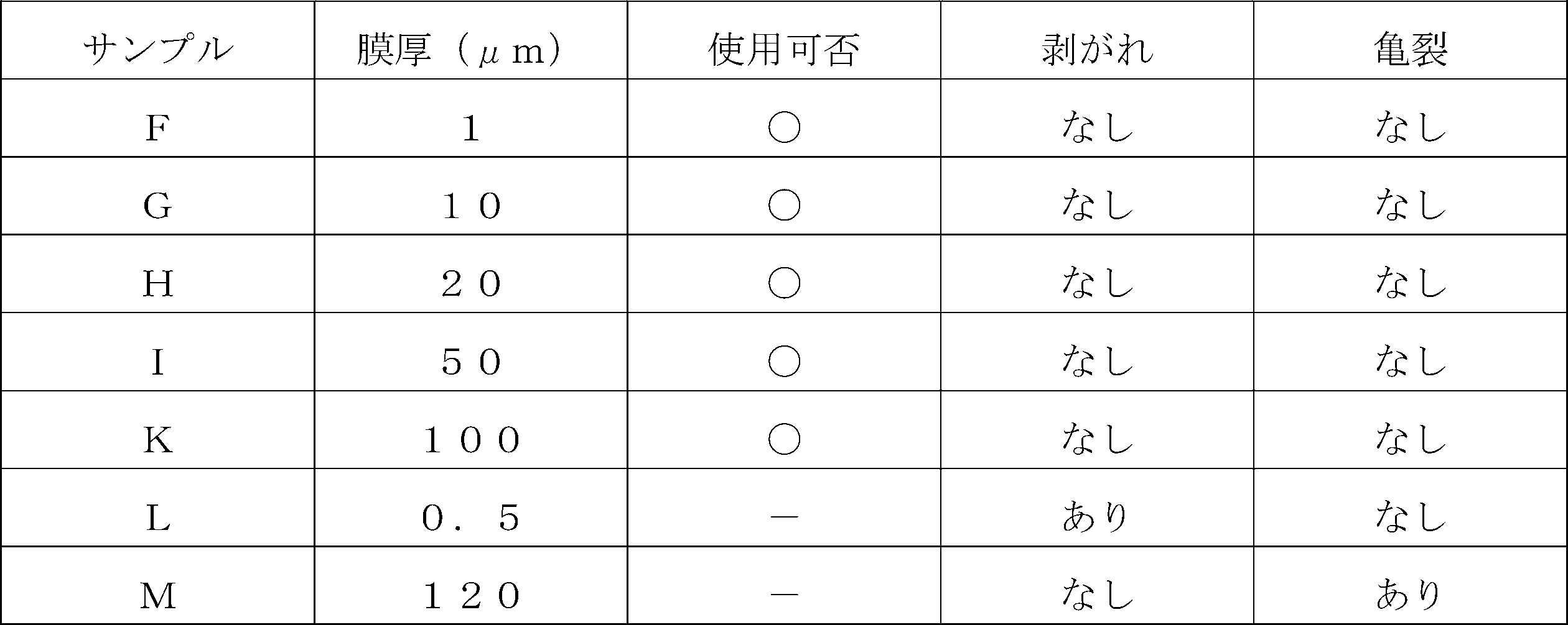
無潤滑環境下において、摺動面の焼き付きが無く、かつ回転密封環20の摺動面21からの黒鉛膜30の剥がれ、亀裂がなかった回転密封環20の黒鉛膜30については、厚み1μm~100μmであることが判明した(サンプルF,G,H,I,K)。
尚、上述したサンプルKの回転密封環20のように、黒鉛膜30が形成されない摺動面21に対して、相手側である静止密封環10が軟質材であるカーボンから形成される場合、摺動面11,21間への異物の侵入により、軟質なカーボンから形成される静止密封環10の摺動面11に異物が噛み込み、摺動面11が削られることにより表面荒れが生じ、摺動面の平滑性が失われて摩擦係数に悪影響を与える。このように、カーボンから形成される摺動部品の摺動面は耐異物性に問題がある。これに対し、本実施例において、回転密封環20は、硬質なSiC基材22に黒鉛膜30が被覆されて構成されるとともに、相手側である静止密封環10も硬質材であるSiCから形成されているため、摺動面11,21間への異物の侵入に対しては、軟質な黒鉛膜30が優先的に削られることとなり、摺動面の摩擦係数に悪影響を与えるようなSiC基材12,22の表面荒れが生じにくくなっている。
以上のように、本発明に係わる回転密封環20のSiC基材22が黒鉛膜30により被覆されることにより、静止密封環10の摺動面11との摩擦によって摺動面21を構成する黒鉛膜30が弱いファンデルワールス力で結合している黒鉛層の層間でせん断されるとともに(図3の拡大部分参照)、摺動面11,21同士の圧接力により軸方向に押し込まれ、SiC基材22の端面部22aの微細凹部22b内に黒鉛膜30の一部が入り込み残ることで摺動面21が平滑化される(図4の拡大部分参照)。これにより、微細凹部22b内に残った黒鉛膜30が静止密封環10の摺動面11に対して黒鉛の自己潤滑性を発揮することができるため、流体潤滑域、境界潤滑域、無潤滑環境下等の広い使用条件において安定して低摩擦効果を得ることができる。さらに、黒鉛膜30は、回転密封環20の摺動面21のみに形成されることにより、摺動面11,21間に発生する黒鉛膜30由来のせん断塊P30(図3の拡大部分参照)は、摺動面11,21同士の圧接力により軸方向に押し込まれ、静止密封環10の摺動面11を構成するSiC基材12の端面部12aの微細凹部12b内に入り込んで移着し、移着膜31を形成することにより、静止密封環10の摺動面11も平滑化される(図4の拡大部分参照)。これにより、摺動面11,21間において、SiCと黒鉛または黒鉛同士の摺動部分の割合が多くなるため、より良好な低摩擦効果を得ることができる。
また、黒鉛膜30の硬度は、静止密封環10の摺動面11、すなわちSiC基材12の硬度よりも小さいことにより、黒鉛膜30が静止密封環10の摺動面11よりも軟質となり、摩擦により静止密封環10の摺動面11を傷つけにくい。さらに、黒鉛膜30の硬度は、回転密封環20のSiC基材22の硬度よりも小さいことにより、摺動面11,21間に異物が侵入した場合、軟質な黒鉛膜30が優先的にせん断されることにより摺動面21の平滑化が促進され、露出した硬質なSiC基材22の端面部22aにより耐異物性を高めることができるため、摺動面11,21間において黒鉛の自己潤滑性と耐異物性とを両立することができる。
また、回転密封環20の基材は、セラミックスであるSiCから形成されており、SiC基材22が多孔質であることから端面部22aに黒鉛膜30の一部が入り込む微細凹部22bが多く存在し、金属よりも表面粗さが出やすいため、黒鉛膜30が基材表面に定着しやすい。さらに、黒鉛膜30が形成されるSiC基材22の端面部22aは、その表面の算術平均粗さRaが0.1μm以上であることにより、端面部22aの微細凹部22b内に黒鉛膜30の一部がより入り込みやすくなるため、静止密封環10の摺動面11との摩擦によって黒鉛膜30がせん断されても、微細凹部22b内に黒鉛膜30の一部が保持され、摺動面11,21間から脱落しにくい。
また、SiC基材22の端面部22aは、黒鉛膜30により全面が被覆される、言い換えれば、基材表面が露出しないことにより、端面部22aにおける全ての微細凹部22b内に黒鉛膜30の一部が入り込んだ状態となるため、黒鉛膜30がせん断されることにより摺動面21が平滑化されやすい。
また、黒鉛膜30は、厚さが1μm~100μmであることにより、SiC基材22の端面部22aからの黒鉛膜30の剥がれや黒鉛膜30に亀裂が生じることを防止することができるため、摺動部品の膜として用いることができる。
さらに、黒鉛膜30は、厚さがSiC基材22の端面部22aの表面における算術平均粗さRaよりも大きい、すなわち黒鉛膜30の厚さがSiC基材22の端面部22aの表面の凹凸よりも大きいことにより、黒鉛膜30の一部がSiC基材22の微細凹部22bに入り込み易く、静止密封環10の摺動面11との摩擦により黒鉛膜30が確実にせん断されるため、微細凹部22b内に黒鉛膜30の一部が残りやすく、低摩擦効果を発揮し易い。
また、黒鉛膜30は、一部にガラス状カーボン領域を含有していることにより、黒鉛膜30のせん断によって生じるせん断塊P30が小さくなりやすく、当該せん断塊P30が相手側である静止密封環10を構成するSiC基材12の微細凹部12b内の奥まで入り込みやすくなるため、静止密封環10の摺動面11に移着膜31が形成されやすい。尚、黒鉛膜30は、一部にガラス状カーボン領域が含有されていても黒鉛層から成る黒鉛領域を主とすることにより、静止密封環10の摺動面11との摩擦により黒鉛の自己潤滑性を発揮することができる。
また、黒鉛膜30は、SiC基材22の端面部22a上に直接形成されることにより、SiC基材22の端面部22aとの密着性が低いため、例えば黒鉛膜30が接着剤を介して接合されている場合と比べて静止密封環10の摺動面11との摩擦により黒鉛膜30にせん断が生じやすく、これにより、黒鉛膜30の剥がれを防止することができる。
また、回転密封環20の基材と摺動面とを別素材により形成することができるため、基材にSiC等のセラミックスの剛性を持たせつつ、摺動面21の黒鉛膜30により黒鉛の自己潤滑性を持たせることができる。さらに、基材を安価な材料に変更することで摺動部品のコストを削減することができる。
以上、本発明の実施例を図面により説明してきたが、具体的な構成はこれら実施例に限られるものではなく、本発明の要旨を逸脱しない範囲における変更や追加があっても本発明に含まれる。
例えば、前記実施例では、摺動部品として、一般産業機械用のメカニカルシールを例に説明したが、自動車やウォータポンプ用等の他のメカニカルシールであってもよい。また、メカニカルシールに限られず、すべり軸受などメカニカルシール以外の摺動部品であってもよい。さらに、黒鉛膜30は、軸受の内周面にも形成可能であるため、ラジアル軸受等を構成する摺動部品にも適用することができる。
また、前記実施例では、摺動部品が適用されるメカニカルシールは、無潤滑環境下で使用されるものとして説明したが、これに限らず、摺動面間に被密封流体である液体を介在させた流体潤滑域や境界潤滑域で使用されてもよい。
また、前記実施例では、黒鉛膜30を回転密封環20にのみ設ける例について説明したが、黒鉛膜30を静止密封環10にのみ設けてもよく、回転密封環20と静止密封環10の両方に設けてもよい。
また、前記実施例では、静止密封環10および回転密封環20はSiCから形成されるものとして説明したが、これに限らず、摺動材料はメカニカルシール用摺動材料として使用されているものであれば適用可能である。尚、SiCとしては、ボロン、アルミニウム、カーボン等を焼結助剤とした焼結体をはじめ、成分、組成の異なる2種類以上の相からなる材料、例えば、黒鉛粒子の分散したSiC、SiCとSiからなる反応焼結SiC等であってもよい。また、上記摺動材料以外では、アルミナ、ジルコニア、窒化ケイ素(Si3N4)等の他のセラミックス、金属材料、樹脂材料、複合材料等も適用可能である。
10 静止密封環(摺動部品)
11 摺動面
12 SiC基材(基材)
12a 端面部
12b 微細凹部
20 回転密封環(摺動部品)
21 摺動面
22 SiC基材(基材)
22a 端面部
22b 微細凹部
30 黒鉛膜
30a 表面
31 移着膜
P30 せん断塊
11 摺動面
12 SiC基材(基材)
12a 端面部
12b 微細凹部
20 回転密封環(摺動部品)
21 摺動面
22 SiC基材(基材)
22a 端面部
22b 微細凹部
30 黒鉛膜
30a 表面
31 移着膜
P30 せん断塊
Claims (8)
- 相対摺動する摺動面を有する摺動部品であって、
前記摺動部品の基材には黒鉛膜が被膜されており、前記摺動面は前記黒鉛膜からなる摺動部品。 - 前記黒鉛膜の硬度は、相手側の摺動面の硬度よりも小さい請求項1に記載の摺動部品。
- 前記黒鉛膜の硬度は、前記基材の硬度よりも小さい請求項1または2に記載の摺動部品。
- 前記黒鉛膜の厚さは、前記基材の表面の算術平均粗さRaよりも大きい請求項1ないし3のいずれかに記載の摺動部品。
- 前記基材は、セラミックスから形成されている請求項1ないし4のいずれかに記載の摺動部品。
- 前記基材の表面の算術平均粗さRaは、0.1μm以上である請求項1ないし5のいずれかに記載の摺動部品。
- 前記基材の表面は、前記黒鉛膜により全面が被覆されている請求項1ないし6のいずれかに記載の摺動部品。
- 前記黒鉛膜は、前記相対摺動する摺動面のうち一方の摺動面のみに形成されている請求項1ないし7のいずれかに記載の摺動部品。
Priority Applications (4)
| Application Number | Priority Date | Filing Date | Title |
|---|---|---|---|
| US17/772,499 US20220389961A1 (en) | 2019-11-15 | 2020-11-02 | Sliding components |
| CN202080074865.6A CN114630970A (zh) | 2019-11-15 | 2020-11-02 | 滑动部件 |
| EP20886813.3A EP4060200A4 (en) | 2019-11-15 | 2020-11-02 | SLIDING COMPONENT |
| JP2021556031A JP7490324B2 (ja) | 2019-11-15 | 2020-11-02 | 摺動部品 |
Applications Claiming Priority (2)
| Application Number | Priority Date | Filing Date | Title |
|---|---|---|---|
| JP2019207206 | 2019-11-15 | ||
| JP2019-207206 | 2019-11-15 |
Publications (1)
| Publication Number | Publication Date |
|---|---|
| WO2021095592A1 true WO2021095592A1 (ja) | 2021-05-20 |
Family
ID=75912360
Family Applications (1)
| Application Number | Title | Priority Date | Filing Date |
|---|---|---|---|
| PCT/JP2020/041089 WO2021095592A1 (ja) | 2019-11-15 | 2020-11-02 | 摺動部品 |
Country Status (5)
| Country | Link |
|---|---|
| US (1) | US20220389961A1 (ja) |
| EP (1) | EP4060200A4 (ja) |
| JP (1) | JP7490324B2 (ja) |
| CN (1) | CN114630970A (ja) |
| WO (1) | WO2021095592A1 (ja) |
Citations (5)
| Publication number | Priority date | Publication date | Assignee | Title |
|---|---|---|---|---|
| JPH0674239A (ja) * | 1992-08-25 | 1994-03-15 | Koyo Seiko Co Ltd | 軸 受 |
| JP2001090766A (ja) * | 1999-09-02 | 2001-04-03 | Illinois Tool Works Inc <Itw> | グラファイト被覆リップシールを備えた空気ダンパー |
| JP2004225725A (ja) | 2003-01-20 | 2004-08-12 | Eagle Ind Co Ltd | 摺動部品 |
| JP2008232014A (ja) * | 2007-03-20 | 2008-10-02 | Sanden Corp | 圧縮機 |
| JP2011058517A (ja) | 2009-09-07 | 2011-03-24 | Nippon Pillar Packing Co Ltd | ドライコンタクトメカニカルシール |
Family Cites Families (14)
| Publication number | Priority date | Publication date | Assignee | Title |
|---|---|---|---|---|
| JP4122305B2 (ja) * | 2004-02-18 | 2008-07-23 | 大同メタル工業株式会社 | 内燃機関用すべり軸受 |
| US20090060408A1 (en) * | 2005-03-02 | 2009-03-05 | Ebara Corporation | Diamond-coated bearing or seal structure and fluid machine comprising the same |
| JP4462077B2 (ja) * | 2005-03-15 | 2010-05-12 | トヨタ自動車株式会社 | 組合せ摺動部材 |
| CN101663495B (zh) * | 2007-04-20 | 2012-07-04 | 株式会社荏原制作所 | 使用了碳系滑动部件的轴承或密封件 |
| JP5223747B2 (ja) * | 2009-03-23 | 2013-06-26 | 株式会社豊田中央研究所 | 摺動部材及びその製造方法 |
| US20110121518A1 (en) * | 2009-11-25 | 2011-05-26 | CHAIR MAN HI-TECH Co., Ltd. | Silicon carbide mechanical seal |
| DE112013001452T5 (de) * | 2012-03-15 | 2015-01-15 | Aktiebolaget Skf | Drehende Patronendichtung mit innenflächigen Dichtungsflächen |
| DE102013005926B4 (de) * | 2013-04-04 | 2015-12-03 | Eagleburgmann Germany Gmbh & Co. Kg | Gleitringdichtungsanordnung mit unterschiedlich harten Gleitflächen |
| JP6422378B2 (ja) * | 2015-03-09 | 2018-11-14 | 日本ピラー工業株式会社 | 端面接触形メカニカルシール |
| KR102394592B1 (ko) * | 2015-03-09 | 2022-05-04 | 니혼삐라아코오교오카부시키가이샤 | 다 유로형 로터리조인트 |
| US10280977B2 (en) * | 2015-04-16 | 2019-05-07 | Eagle Industry Co., Ltd | Slide Component |
| US20180291815A1 (en) * | 2017-04-10 | 2018-10-11 | Rolls-Royce Corporation | Reduced friction intershaft seal assembly |
| JP6895331B2 (ja) | 2017-07-04 | 2021-06-30 | イーグル工業株式会社 | メカニカルシール |
| CN110296149A (zh) * | 2019-07-17 | 2019-10-01 | 浙江中达精密部件股份有限公司 | 一种金属滑动构件及其制备方法 |
-
2020
- 2020-11-02 JP JP2021556031A patent/JP7490324B2/ja active Active
- 2020-11-02 US US17/772,499 patent/US20220389961A1/en active Pending
- 2020-11-02 CN CN202080074865.6A patent/CN114630970A/zh active Pending
- 2020-11-02 WO PCT/JP2020/041089 patent/WO2021095592A1/ja unknown
- 2020-11-02 EP EP20886813.3A patent/EP4060200A4/en active Pending
Patent Citations (5)
| Publication number | Priority date | Publication date | Assignee | Title |
|---|---|---|---|---|
| JPH0674239A (ja) * | 1992-08-25 | 1994-03-15 | Koyo Seiko Co Ltd | 軸 受 |
| JP2001090766A (ja) * | 1999-09-02 | 2001-04-03 | Illinois Tool Works Inc <Itw> | グラファイト被覆リップシールを備えた空気ダンパー |
| JP2004225725A (ja) | 2003-01-20 | 2004-08-12 | Eagle Ind Co Ltd | 摺動部品 |
| JP2008232014A (ja) * | 2007-03-20 | 2008-10-02 | Sanden Corp | 圧縮機 |
| JP2011058517A (ja) | 2009-09-07 | 2011-03-24 | Nippon Pillar Packing Co Ltd | ドライコンタクトメカニカルシール |
Non-Patent Citations (1)
| Title |
|---|
| See also references of EP4060200A4 |
Also Published As
| Publication number | Publication date |
|---|---|
| EP4060200A1 (en) | 2022-09-21 |
| EP4060200A4 (en) | 2024-01-24 |
| CN114630970A (zh) | 2022-06-14 |
| JP7490324B2 (ja) | 2024-05-27 |
| US20220389961A1 (en) | 2022-12-08 |
| JPWO2021095592A1 (ja) | 2021-05-20 |
Similar Documents
| Publication | Publication Date | Title |
|---|---|---|
| Marian et al. | Layered 2D nanomaterials to tailor friction and wear in machine elements—A review | |
| AU2016248669B2 (en) | Sliding part | |
| JP5278970B2 (ja) | メカニカルシール摺動材及びメカニカルシール | |
| CN100567779C (zh) | 机械密封装置、滑动部件及其制造方法 | |
| WO2018070265A1 (ja) | 摺動部品 | |
| CN112204279B (zh) | 轴密封装置 | |
| JP2024506966A (ja) | 低摩擦コーティング | |
| JP4586002B2 (ja) | メカニカルシール | |
| WO2021095592A1 (ja) | 摺動部品 | |
| JP4094176B2 (ja) | メカニカルシール | |
| EP3330581B1 (en) | Sliding member and method for producing a sliding member | |
| EP4317729A1 (en) | Sliding component | |
| WO2022209966A1 (ja) | 摺動部品 | |
| JP5302963B2 (ja) | 摺動部材およびメカニカルシール | |
| KR101059461B1 (ko) | 윤활제 및 접동부재 | |
| JP2001026792A5 (ja) | ||
| CN111316009A (zh) | 半分割推力轴承、推力轴承、轴承装置以及内燃机 | |
| JP5626715B2 (ja) | 摺動部材およびメカニカルシール | |
| WO2020209262A1 (ja) | 摺動部品 | |
| JP2006144979A (ja) | 回転ダイヤモンド摺動体による摩擦低減方法 | |
| JPH11141690A (ja) | 密封装置 | |
| JP6155709B2 (ja) | 摺動部材、軸受部材、シール部材、および、装置 | |
| JPH10103362A (ja) | 摺動部材および転がり軸受 |
Legal Events
| Date | Code | Title | Description |
|---|---|---|---|
| 121 | Ep: the epo has been informed by wipo that ep was designated in this application |
Ref document number: 20886813 Country of ref document: EP Kind code of ref document: A1 |
|
| ENP | Entry into the national phase |
Ref document number: 2021556031 Country of ref document: JP Kind code of ref document: A |
|
| NENP | Non-entry into the national phase |
Ref country code: DE |
|
| ENP | Entry into the national phase |
Ref document number: 2020886813 Country of ref document: EP Effective date: 20220615 |