WO2021095127A1 - Reception device - Google Patents
Reception device Download PDFInfo
- Publication number
- WO2021095127A1 WO2021095127A1 PCT/JP2019/044394 JP2019044394W WO2021095127A1 WO 2021095127 A1 WO2021095127 A1 WO 2021095127A1 JP 2019044394 W JP2019044394 W JP 2019044394W WO 2021095127 A1 WO2021095127 A1 WO 2021095127A1
- Authority
- WO
- WIPO (PCT)
- Prior art keywords
- wave
- receiving device
- fir filters
- receiver
- receivers
- Prior art date
Links
Images


Classifications
-
- H—ELECTRICITY
- H04—ELECTRIC COMMUNICATION TECHNIQUE
- H04B—TRANSMISSION
- H04B17/00—Monitoring; Testing
- H04B17/20—Monitoring; Testing of receivers
- H04B17/21—Monitoring; Testing of receivers for calibration; for correcting measurements
-
- H—ELECTRICITY
- H04—ELECTRIC COMMUNICATION TECHNIQUE
- H04B—TRANSMISSION
- H04B11/00—Transmission systems employing sonic, ultrasonic or infrasonic waves
-
- H—ELECTRICITY
- H04—ELECTRIC COMMUNICATION TECHNIQUE
- H04B—TRANSMISSION
- H04B13/00—Transmission systems characterised by the medium used for transmission, not provided for in groups H04B3/00 - H04B11/00
- H04B13/02—Transmission systems in which the medium consists of the earth or a large mass of water thereon, e.g. earth telegraphy
Definitions
- the present invention relates to a technique for receiving sound waves in water.
- the waveform distortion pattern (hereinafter referred to as "propagation path characteristic") fluctuates with time as the phase difference between the direct wave and the delayed wave changes.
- the magnitude of the delay spread and the magnitude of the Doppler spread are both proportional to the reciprocal of the propagation velocity. Therefore, the delay spread and Doppler spread when sound waves are used in water are about 200,000 times larger than the delay spread and Doppler spread when electromagnetic waves are used in air, respectively. Therefore, in order to enable information transmission using sound waves, it is necessary to continue to compensate for waveform distortion that fluctuates at high speed.
- Patent Document 1 As a technique for solving such a problem peculiar to underwater acoustic communication, an adaptive equalization technique for adaptively calculating and applying an FIR filter having an inverse characteristic of propagation path characteristics between transmitters and receivers has been proposed (for example, non-adaptive).
- Patent Document 1 An adaptive equalization technique for adaptively calculating and applying an FIR filter having an inverse characteristic of propagation path characteristics between transmitters and receivers has been proposed (for example, non-adaptive).
- FIG. 5 is a diagram showing a specific example of the receiving device 90 to which the adaptive equalization technique shown in Non-Patent Document 1 is applied.
- the receiving device 10 includes a receiver 901, a conversion unit 902, an FIR (Finite Impulse Response) filter 903, a symbol estimation unit 904, and a filter coefficient calculation unit 905.
- the receiver 901 converts sound waves in water into electrical signals.
- the conversion unit 902 samples the signal received by the receiver 901.
- the FIR filter 903 manipulates the waveform of the sampled signal.
- the symbol estimation unit 904 estimates the transmitted symbol based on the signal that has passed through the FIR filter 903.
- the filter coefficient calculation unit 905 adaptively calculates the tap coefficient of the FIR filter 903 so that the error between the signal passing through the FIR filter 903 and the estimated symbol is minimized.
- the FIR filter 903 has a tap length long enough to cover the delay spread. That is, assuming that the delay spread is ⁇ _T seconds and the sampling rate of the FIR filter 903 is f_s hertz, the number of taps N_tap is expressed by the following equation (1).
- the FIR filter 903 that covers a longer time length than the delay spread is adaptively optimized.
- the waveform distortion generated by the superposition of the direct wave and the delayed wave can be compensated by the FIR filter 903. That is, it is possible to dynamically configure an equalization filter having the inverse characteristic of the propagation path characteristic. By such processing, compensation for poor and time-varying waveform distortion is realized.
- Non-Patent Document 1 a configuration using a plurality of receivers 901 and a plurality of FIR filters 903 connected to the receivers 901 has also been proposed. Also in this configuration, the number of taps of the FIR filter 903 is designed to satisfy the equation (1) as in the above-described configuration.
- Each FIR filter 903 operates to compensate for the waveform distortion generated between the respective transmitters and receivers. That is, each FIR filter 903 operates so as to form an equalization filter having an inverse characteristic of the propagation path characteristic, and a plurality of receivers 901 are used for the purpose of obtaining a diversity effect.
- the size of the Doppler spread is proportional to the frequency used and the moving speed. Therefore, when a high frequency band is used for high-speed communication, or when the transmitter or receiver moves at high speed, it is difficult to sufficiently compensate for waveform distortion by the conventional technique. As a result, information cannot be transmitted. For this reason, the communication speed of conventional underwater acoustic equipment has been limited to several tens of kbps. Therefore, it has been difficult to apply communication using underwater audio equipment to a high-speed mobile environment.
- an object of the present invention is to provide a technique capable of reducing the influence of waveform distortion due to delay spread.
- One aspect of the present invention includes M receivers that receive signals based on sound waves propagating in water, M FIR filters that waveform-manipulate the signals received by the receiver, and M said.
- a synthesizer that synthesizes the output signals of the FIR filters and a filter coefficient calculation unit that calculates the tap coefficients of the M FIR filters so as to reduce the error of the output signals synthesized by the synthesizer are provided.
- the tap length of the M FIR filters is shorter than the delay spread, which is the possible width of the arrival time of the direct wave and the delay wave of the sound wave.
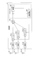
- FIG. 1 is a schematic block diagram showing an outline of the functional configuration of the receiving device 10 of the present invention.
- a plurality of FIR filters 103 having a tap length sufficiently shorter than the assumed delay spread ⁇ _T are provided.
- the tap length is a value obtained by multiplying the sampling time interval by the number of taps. Since such a tap-length FIR filter 103 is used, each FIR filter 103 cannot form a filter having the opposite characteristic of waveform distortion.
- the delayed wave which is the root cause of the waveform distortion, can be spatially removed. Therefore, it is possible to reduce the influence of waveform distortion due to a large delay spread.
- the details of the receiving device 10 of the present invention will be described.
- the receiving device 10 includes M receivers 101 (101_1 to 101_M), M conversion units 102 (102_1 to 102_M), M FIR filters 103 (103_1 to 103_M), a synthesizer 104, and a symbol estimation unit 105. And the filter coefficient calculation unit 106 is provided. M is an integer greater than or equal to 2. It is desirable that the same number of receiver 101, conversion unit 102, and FIR filter 103 are provided. In the following description, the configuration common to the M devices having the same name will be described by omitting the reference numerals such as “_1”. For example, the receiver is described as "receiver 101" instead of "receiver 101_1".
- the receiver 101 receives the sound wave propagating in the water and converts the received sound wave into an electric signal.
- the conversion unit 102 samples the electric signal converted by the receiver 101. Specifically, it is as follows. The conversion unit 102 performs analog-to-digital conversion on the electric signal converted by the receiver 101. Then, the conversion unit 102 performs frequency conversion on the digital signal obtained by the analog-to-digital conversion. Although other configurations (modification examples) may be adopted for the conversion unit 102, each modification will be described later.
- the FIR filter 103 performs waveform manipulation on the signal sampled by the conversion unit 102.
- the number of taps of the FIR filter 103 is set so that a tap length sufficiently shorter than the expected delay spread ⁇ _T can be secured. That is, the number of taps of the FIR filter 103 is set based on the sampling time interval and the assumed delay spread ⁇ _T.
- the synthesizer 104 synthesizes M signals after the waveform is manipulated by the FIR filter 103.
- the symbol estimation unit 105 estimates the symbol contained in the sound wave propagating in the water based on the signal after being synthesized by the synthesizer 104. In other words, it estimates the symbols that the received sound waves contained at the time they were transmitted.
- the filter coefficient calculation unit 106 adaptively calculates the tap coefficients of the M FIR filters 103.
- the tap coefficient is adaptively calculated so that the error between the symbol indicated by the output signal of the synthesizer 104 and the symbol estimated by the symbol estimation unit 105 is minimized.
- the number of taps N taps of the FIR filters 103_1 to 103_M are given by the following equation 2. It is expressed as. Since d is the largest distance among the distances between the receivers 101 as described above, if all the distances between the receivers 101 are uniform, the uniform distance becomes the value of d.
- the number of taps is designed so that the tap length is sufficiently shorter than the possible width (delay spread) of the delay time between the direct wave and the delayed wave, and is longer than the arrival time difference between the receivers 101.
- This number of taps may be common to all M FIR filters 103.
- Sufficiently shorter than the delay spread ( ⁇ _T) may be, for example, one tenth of the delay spread or one hundredth of the delay spread. For example, taking a value closer to d / c than an intermediate value between the delay spread and the value of d / c may be defined as being sufficiently shorter than the delay spread.
- the receiving device 10 of the present embodiment a plurality of receiving sequences (combination of the receiver 101, the conversion unit 102, and the FIR filter 103) are provided.
- the tap length of each FIR filter 103 is set sufficiently shorter than the delay spread as described above.
- the filter coefficient calculation unit 106 adaptively optimizes the FIR filter 103 in such a plurality of reception sequences. Since the tap lengths of the FIR filters 103_1 to 103_M are sufficiently shorter than the delay spread, it is not possible to construct a filter having the opposite characteristic of waveform distortion.
- a waveform equalization approach completely different from the conventional one is applied, which is to spatially remove the delayed wave which is the root cause of the waveform distortion.
- FIG. 2 is a diagram showing the operating principle of the receiving device 10.
- the transmitted signal is a pulse signal
- the number of receivers 101 is two (101_a and 101_b)
- the number of delayed waves is one, in order to aid an intuitive understanding.
- the FIR filter 103_c is further connected to the subsequent stage of the synthesizer 104
- the FIR filters 103_1 to 103_M are separated into two FIR filters 103a and 103b, respectively, and placed after the synthesizer 104. That is, the configuration shown in FIG. 2 can perform an operation equivalent to that of the receiving device 10.
- time shift and dephase are performed as waveform operations so that the two delayed waves are in opposite phase at the same time.
- the delayed wave component disappears in the synthesized signal.
- the FIR filter 101_c in the subsequent stage compensates for the waveform distortion due to the superposition of the direct waves. Waveform equalization is completed by the above processing.
- the arrival time difference between the direct waves and the arrival time difference between the delayed waves between the receivers 101 is determined by the distance between the transmitted and received waves at most, and is overwhelming than the time difference (delay spread) between the direct wave and the delayed wave. Short. Therefore, the waveform operation described with reference to FIG. 2 can be realized by the FIR filter 103 having an extremely short tap length. Further, the arrival time difference and phase difference between the direct waves and the arrival time difference and phase difference between the delayed waves between the receivers 101 are constant as long as the arrival directions of the direct wave and the delayed wave do not change. Therefore, it is more stable than the time difference and phase difference between the direct wave and the delayed wave.
- the configuration as shown in FIG. 1 or the configuration as shown in FIG. 2 may be used.
- the error characteristic curved surface becomes a fourth-order function, and as a result, the configuration has a local minimum solution. Therefore, there is a possibility that the adaptive algorithm such as LMS or RLS will converge to an erroneous filter coefficient. This is also disclosed in the following references.
- each FIR filter 103 has a function of the first-stage FIR filter 103 (103_a or 103_b) in FIG. 2 and the second-stage FIR filter 103 (103_c).
- the receiving device 10 of the present embodiment has an ability to remove a number of delayed waves that is one less than the number M of the receivers 101. Therefore, the natural number "M", which is the number of the receiver 101 and the FIR filter 103 (the number of reception series), is a delayed wave (processed as a removal target) scheduled to reach the receiver 101. It is desirable to make it a positive integer larger than the number of delayed waves).
- FIG. 3 is a table showing the execution conditions of the simulation of the conventional receiving device and the receiving device 10 in the present embodiment.
- FIG. 4 is a graph showing the results of a simulation performed under the implementation conditions shown in FIG. Specifically, FIG. 4 shows the bit error rate after the symbol determination with respect to the moving speed as a result of the simulation.
- the conventional receiving device in high-speed communication of 400 kbps (200 kbps, QPSK), the conventional receiving device cannot update the filter in time when the moving speed exceeds 0.001 m / s, and the bit error rate deteriorates. Begins. Therefore, it is not possible to follow slight changes in the propagation path such as waves and tidal currents, and it is practically difficult to communicate even in a fixed environment.
- the receiving device 10 can keep a bit error rate of 0.1% or less even in an ultra-high-speed moving environment exceeding 10 m / s.
- the simulation result shows that the conventional receiving device has better bit error rate characteristics.
- the conventional receiving device can perform ideal waveform equalization compensated by the filter having the opposite characteristic of the propagation path as long as the update of the filter catches up.
- the tap length sufficiently shorter than the delay spread is applied to the FIR filter 103 connected to the plurality of receivers 101. Then, a configuration is adopted in which the filter coefficient of the FIR filter 103 is adaptively optimized. With such a configuration, it is possible to spatially remove the delayed wave, which is the root cause of the waveform distortion. Since the delayed wave is spatially removed, high-speed communication in an underwater high-speed moving environment is possible.
- the conversion unit 102 may be configured to perform only analog-to-digital conversion.
- the conversion unit 102 may be configured to perform frequency conversion on the analog signal and then perform analog-to-digital conversion.
- the physical intervals of the M receivers 101 may be all equal or may be different individually.
- a feedback filter for removing the residual error of the FIR filter (feedforward filter) as described in Non-Patent Document 1 may be connected to the subsequent stage.
- the symbol estimation unit 105 and the filter coefficient calculation unit 106 of the receiving device 10 are respectively configured by using a processor such as a CPU and a memory.
- the symbol estimation unit 105 and the filter coefficient calculation unit 106 operate by the processor reading and executing the program stored in the storage device.
- the program may be recorded on a computer-readable recording medium.
- the computer-readable recording medium is, for example, a flexible disk, a magneto-optical disk, a portable medium such as a ROM or a CD-ROM, or a non-temporary storage medium such as a storage device such as a hard disk built in a computer system.
- the program may be transmitted over a telecommunication line.
- Part or all of the operations of the symbol estimation unit 105 and the filter coefficient calculation unit 106 may be realized by using hardware including an electronic circuit using, for example, LSI, ASIC, PLD, FPGA, or the like.
- the present invention is applicable to communication using sound waves in water.
Abstract
Description

[概略]
図1は、本発明の受信装置10の機能構成の概略を示す概略ブロック図である。本発明の受信装置10では、想定される遅延広がりσ_Tよりも十分に短いタップ長を有したFIRフィルター103が複数設けられる。タップ長とは、サンプリングの時間間隔と、タップ数とを乗じて得られる値である。このようなタップ長のFIRフィルター103が用いられるため、各FIRフィルター103は、波形歪みの逆特性のフィルターを構成することはできない。しかしながら、本発明の受信装置10では、波形歪みの根本的な原因である遅延波を空間的に除去することができる。そのため、大きな遅延広がりによる波形歪みの影響を軽減することが可能となる。以下、本発明の受信装置10の詳細について説明する。 An embodiment of the receiving device of the present invention will be described in detail with reference to the drawings.
[Summary]
FIG. 1 is a schematic block diagram showing an outline of the functional configuration of the
受信装置10は、M台の受波器101(101_1~101_M)、M台の変換部102(102_1~102_M)、M台のFIRフィルター103(103_1~103_M)、合成器104、シンボル推定部105及びフィルター係数計算部106を備える。Mは、2以上の整数である。受波器101、変換部102及びFIRフィルター103は、いずれも同数設けられることが望ましい。なお、以下の説明では、M台の同名の装置に共通する構成に関しては、“_1”等の符号を省略して記載する。例えば、受波器に関しては、“受波器101_1”ではなく、“受波器101”と記載する。 [Details]
The

本実施形態において、変換部102は、アナログデジタル変換のみを行うように構成されてもよい。変換部102は、アナログ信号に対して周波数変換を行い、その後にアナログデジタル変換を行うように構成されてもよい。 [Modification example]
In the present embodiment, the conversion unit 102 may be configured to perform only analog-to-digital conversion. The conversion unit 102 may be configured to perform frequency conversion on the analog signal and then perform analog-to-digital conversion.
Claims (5)
- 水中を伝搬する音波に基づく信号を受信するM個の受波器と、
前記受波器によって受信された信号を波形操作するM個のFIRフィルターと、
M個の前記FIRフィルターの出力信号を合成する合成器と、
前記合成器によって合成された出力信号の誤差を小さくするように、前記M個のFIRフィルターのタップ係数を計算するフィルター係数計算部と、
を備え、
前記M個のFIRフィルターのタップ長は、前記音波の直接波と遅延波との到来時間の取り得る幅である遅延広がりよりも短い、受信装置。 M receivers that receive signals based on sound waves propagating in water,
M FIR filters that manipulate the waveform of the signal received by the receiver, and
A synthesizer that synthesizes the output signals of the M FIR filters, and
A filter coefficient calculation unit that calculates the tap coefficient of the M FIR filters so as to reduce the error of the output signal synthesized by the synthesizer.
With
A receiver in which the tap length of the M FIR filters is shorter than the delay spread, which is the possible width of the arrival time of the direct wave and the delay wave of the sound wave. - 前記タップ長は、M個の前記受波器間の距離のうち最も大きい距離を、水中での音速で割って得られる時間よりも長い、請求項1に記載の受信装置。 The receiving device according to claim 1, wherein the tap length is longer than the time obtained by dividing the largest distance among the M receivers by the speed of sound in water.
- 前記Mの値は、処理の対象となる遅延波の数よりも大きい正の整数である、請求項1又は2に記載の受信装置。 The receiving device according to claim 1 or 2, wherein the value of M is a positive integer larger than the number of delayed waves to be processed.
- 前記受波器によって受信された前記音波をデジタル信号に変換するM個の変換部をさらに備える、請求項1に記載の受信装置。 The receiving device according to claim 1, further comprising M conversion units that convert the sound waves received by the receiver into digital signals.
- 前記変換部は、前記音波の信号について周波数変換をさらに行う、請求項4に記載の受信装置。 The receiving device according to claim 4, wherein the conversion unit further performs frequency conversion on the sound wave signal.
Priority Applications (6)
| Application Number | Priority Date | Filing Date | Title |
|---|---|---|---|
| CN201980102110.XA CN114667693A (en) | 2019-11-12 | 2019-11-12 | Receiving apparatus |
| KR1020227015386A KR20220079628A (en) | 2019-11-12 | 2019-11-12 | receiving device |
| JP2021555662A JP7208570B2 (en) | 2019-11-12 | 2019-11-12 | receiver |
| US17/774,451 US11888538B2 (en) | 2019-11-12 | 2019-11-12 | Receiving apparatus |
| PCT/JP2019/044394 WO2021095127A1 (en) | 2019-11-12 | 2019-11-12 | Reception device |
| EP19952595.7A EP4060908A4 (en) | 2019-11-12 | 2019-11-12 | Reception device |
Applications Claiming Priority (1)
| Application Number | Priority Date | Filing Date | Title |
|---|---|---|---|
| PCT/JP2019/044394 WO2021095127A1 (en) | 2019-11-12 | 2019-11-12 | Reception device |
Publications (1)
| Publication Number | Publication Date |
|---|---|
| WO2021095127A1 true WO2021095127A1 (en) | 2021-05-20 |
Family
ID=75911999
Family Applications (1)
| Application Number | Title | Priority Date | Filing Date |
|---|---|---|---|
| PCT/JP2019/044394 WO2021095127A1 (en) | 2019-11-12 | 2019-11-12 | Reception device |
Country Status (6)
| Country | Link |
|---|---|
| US (1) | US11888538B2 (en) |
| EP (1) | EP4060908A4 (en) |
| JP (1) | JP7208570B2 (en) |
| KR (1) | KR20220079628A (en) |
| CN (1) | CN114667693A (en) |
| WO (1) | WO2021095127A1 (en) |
Cited By (1)
| Publication number | Priority date | Publication date | Assignee | Title |
|---|---|---|---|---|
| US20220393778A1 (en) * | 2019-11-12 | 2022-12-08 | Nippon Telegraph And Telephone Corporation | Receiving apparatus |
Citations (3)
| Publication number | Priority date | Publication date | Assignee | Title |
|---|---|---|---|---|
| JP2001257627A (en) * | 2000-03-13 | 2001-09-21 | Kawasaki Steel Corp | Wireless receiver |
| JP2002026780A (en) * | 2000-06-20 | 2002-01-25 | Samsung Electronics Co Ltd | Method and device for adjusting length of filter tap for adaptive equalizer employing training sequence |
| JP2006323395A (en) * | 1994-06-15 | 2006-11-30 | Sony Corp | Signal processing apparatus and sound reproducing apparatus |
Family Cites Families (12)
| Publication number | Priority date | Publication date | Assignee | Title |
|---|---|---|---|---|
| US4947425A (en) * | 1989-10-27 | 1990-08-07 | At&T Bell Laboratories | Echo measurement arrangement |
| JP4113651B2 (en) * | 2000-04-10 | 2008-07-09 | 日本放送協会 | Digital broadcast receiver |
| JP4608557B2 (en) * | 2005-03-01 | 2011-01-12 | エレクトロビット システム テスト オーイー | Method, apparatus mechanism, transmitter unit, and receiver unit for generating a data characterization MIMO environment |
| NO322301B1 (en) * | 2005-07-13 | 2006-09-11 | Tandberg Telecom As | Small delay echo cancellation method and system. |
| KR100775128B1 (en) * | 2006-10-25 | 2007-11-08 | 한국해양연구원 | Method and apparatus for phase shift keying underwater acoustic communication |
| JP5352952B2 (en) * | 2006-11-07 | 2013-11-27 | ソニー株式会社 | Digital filter circuit, digital filter program and noise canceling system |
| KR101005843B1 (en) * | 2009-05-11 | 2011-01-05 | 한국해양연구원 | Method and Apparatus for the Hybrid Augmented Channel Equalization of the Receiver for Underwater Acoustic Communication |
| CN101656696B (en) * | 2009-09-18 | 2012-03-07 | 南京信息工程大学 | Frequency-domain small wave blind equalization method based on united combining space-time diversity |
| WO2011100868A1 (en) * | 2010-02-20 | 2011-08-25 | Huawei Technologies Co., Ltd. | Filter device and method for providing a filter device |
| CN105471779B (en) * | 2015-12-08 | 2018-08-31 | 扬智科技股份有限公司 | Bearing calibration and correcting circuit |
| US11888538B2 (en) * | 2019-11-12 | 2024-01-30 | Nippon Telegraph And Telephone Corporation | Receiving apparatus |
| CN111884970A (en) * | 2020-06-23 | 2020-11-03 | 黑龙江科技大学 | Taylor-FFT demodulation method based on underwater acoustic communication |
-
2019
- 2019-11-12 US US17/774,451 patent/US11888538B2/en active Active
- 2019-11-12 KR KR1020227015386A patent/KR20220079628A/en unknown
- 2019-11-12 JP JP2021555662A patent/JP7208570B2/en active Active
- 2019-11-12 WO PCT/JP2019/044394 patent/WO2021095127A1/en unknown
- 2019-11-12 CN CN201980102110.XA patent/CN114667693A/en active Pending
- 2019-11-12 EP EP19952595.7A patent/EP4060908A4/en active Pending
Patent Citations (3)
| Publication number | Priority date | Publication date | Assignee | Title |
|---|---|---|---|---|
| JP2006323395A (en) * | 1994-06-15 | 2006-11-30 | Sony Corp | Signal processing apparatus and sound reproducing apparatus |
| JP2001257627A (en) * | 2000-03-13 | 2001-09-21 | Kawasaki Steel Corp | Wireless receiver |
| JP2002026780A (en) * | 2000-06-20 | 2002-01-25 | Samsung Electronics Co Ltd | Method and device for adjusting length of filter tap for adaptive equalizer employing training sequence |
Non-Patent Citations (3)
| Title |
|---|
| HIROSHI OCHI: "Research on Underwater High-Speed Acoustic Transmission of Digital Data Using Wideband Transducers", THE UNIVERSITY OF ELECTRO-COMMUNICATIONS DOCTORAL THESIS, March 2009 (2009-03-01) |
| KAZUNORI HAYASHISHINSUKE HARA: "A Spatio-Temporal Equalization Method with Cascade Configuration of an Adaptive Antenna Array and a Decision Feedback Equalizer", THE TRANSACTIONS OF THE INSTITUTE OF ELECTRONICS, INFORMATION AND COMMUNICATION ENGINEERS. B, vol. J85-B, no. 6, pages 900 - 909 |
| See also references of EP4060908A4 |
Cited By (2)
| Publication number | Priority date | Publication date | Assignee | Title |
|---|---|---|---|---|
| US20220393778A1 (en) * | 2019-11-12 | 2022-12-08 | Nippon Telegraph And Telephone Corporation | Receiving apparatus |
| US11888538B2 (en) * | 2019-11-12 | 2024-01-30 | Nippon Telegraph And Telephone Corporation | Receiving apparatus |
Also Published As
| Publication number | Publication date |
|---|---|
| JP7208570B2 (en) | 2023-01-19 |
| CN114667693A (en) | 2022-06-24 |
| JPWO2021095127A1 (en) | 2021-05-20 |
| US11888538B2 (en) | 2024-01-30 |
| KR20220079628A (en) | 2022-06-13 |
| EP4060908A4 (en) | 2023-08-02 |
| US20220393778A1 (en) | 2022-12-08 |
| EP4060908A1 (en) | 2022-09-21 |
Similar Documents
| Publication | Publication Date | Title |
|---|---|---|
| Farhang-Boroujeny | Adaptive filters: theory and applications | |
| JP5029355B2 (en) | Adaptive digital filter, FM receiver, signal processing method, and program | |
| JP4455015B2 (en) | Canceller circuit and control method | |
| KR100926983B1 (en) | Adaptive digital filter, FM receiver, signal processing method and program | |
| US8804794B2 (en) | Adjustable latency transceiver processing | |
| JPS58501977A (en) | Interference cancellation method and device | |
| CN101106386A (en) | Time domain self-adapted balancer | |
| CA2284989C (en) | Combined parallel adaptive equalizer/echo canceller | |
| WO2021095127A1 (en) | Reception device | |
| KR100748642B1 (en) | Interference signal cancellation method for mobile communication repeaters | |
| JP4829977B2 (en) | Waveform equalizer | |
| CN101521643B (en) | Method and system for processing interference signal | |
| RU2782244C1 (en) | Receiver | |
| US7957456B2 (en) | Selection of filter coefficients for tranceiver non-linearity signal cancellation | |
| Ling | Achievable performance and limiting factors of echo cancellation in wireless communications | |
| WO2024023933A1 (en) | Antenna device | |
| WO2022244125A1 (en) | Receiver and receiving method | |
| JP2009044211A (en) | Waveform equalizer and control method thereof, and reception device and control method thereof | |
| KR100656786B1 (en) | Base multi station system and method for calibration of many-channel receiver | |
| Kun et al. | A SE-CMA based blind equalization for MIMO systems | |
| Umer | Adaptive lms based channel equalization | |
| JP5754353B2 (en) | Radio signal receiving method and receiving apparatus | |
| US9407472B1 (en) | Fast transversal multi-input system | |
| JPH09307488A (en) | Receiver | |
| Romero et al. | Time reversal acoustic communication receivers: DSP implementation and fast channel estimation |
Legal Events
| Date | Code | Title | Description |
|---|---|---|---|
| 121 | Ep: the epo has been informed by wipo that ep was designated in this application |
Ref document number: 19952595 Country of ref document: EP Kind code of ref document: A1 |
|
| ENP | Entry into the national phase |
Ref document number: 2021555662 Country of ref document: JP Kind code of ref document: A |
|
| ENP | Entry into the national phase |
Ref document number: 20227015386 Country of ref document: KR Kind code of ref document: A |
|
| NENP | Non-entry into the national phase |
Ref country code: DE |
|
| ENP | Entry into the national phase |
Ref document number: 2019952595 Country of ref document: EP Effective date: 20220613 |