WO2021085663A1 - Dispositif électronique pour pilotage d'application, et son procédé de commande - Google Patents
Dispositif électronique pour pilotage d'application, et son procédé de commande Download PDFInfo
- Publication number
- WO2021085663A1 WO2021085663A1 PCT/KR2019/014359 KR2019014359W WO2021085663A1 WO 2021085663 A1 WO2021085663 A1 WO 2021085663A1 KR 2019014359 W KR2019014359 W KR 2019014359W WO 2021085663 A1 WO2021085663 A1 WO 2021085663A1
- Authority
- WO
- WIPO (PCT)
- Prior art keywords
- application
- resource allocation
- allocation information
- display
- electronic device
- Prior art date
Links
Images


Classifications
-
- G—PHYSICS
- G06—COMPUTING; CALCULATING OR COUNTING
- G06F—ELECTRIC DIGITAL DATA PROCESSING
- G06F9/00—Arrangements for program control, e.g. control units
- G06F9/06—Arrangements for program control, e.g. control units using stored programs, i.e. using an internal store of processing equipment to receive or retain programs
- G06F9/46—Multiprogramming arrangements
- G06F9/48—Program initiating; Program switching, e.g. by interrupt
- G06F9/4806—Task transfer initiation or dispatching
- G06F9/4843—Task transfer initiation or dispatching by program, e.g. task dispatcher, supervisor, operating system
- G06F9/4881—Scheduling strategies for dispatcher, e.g. round robin, multi-level priority queues
- G06F9/4893—Scheduling strategies for dispatcher, e.g. round robin, multi-level priority queues taking into account power or heat criteria
-
- G—PHYSICS
- G06—COMPUTING; CALCULATING OR COUNTING
- G06F—ELECTRIC DIGITAL DATA PROCESSING
- G06F9/00—Arrangements for program control, e.g. control units
- G06F9/06—Arrangements for program control, e.g. control units using stored programs, i.e. using an internal store of processing equipment to receive or retain programs
- G06F9/46—Multiprogramming arrangements
- G06F9/50—Allocation of resources, e.g. of the central processing unit [CPU]
- G06F9/5094—Allocation of resources, e.g. of the central processing unit [CPU] where the allocation takes into account power or heat criteria
-
- G—PHYSICS
- G06—COMPUTING; CALCULATING OR COUNTING
- G06F—ELECTRIC DIGITAL DATA PROCESSING
- G06F3/00—Input arrangements for transferring data to be processed into a form capable of being handled by the computer; Output arrangements for transferring data from processing unit to output unit, e.g. interface arrangements
- G06F3/01—Input arrangements or combined input and output arrangements for interaction between user and computer
- G06F3/048—Interaction techniques based on graphical user interfaces [GUI]
- G06F3/0481—Interaction techniques based on graphical user interfaces [GUI] based on specific properties of the displayed interaction object or a metaphor-based environment, e.g. interaction with desktop elements like windows or icons, or assisted by a cursor's changing behaviour or appearance
-
- G—PHYSICS
- G06—COMPUTING; CALCULATING OR COUNTING
- G06F—ELECTRIC DIGITAL DATA PROCESSING
- G06F3/00—Input arrangements for transferring data to be processed into a form capable of being handled by the computer; Output arrangements for transferring data from processing unit to output unit, e.g. interface arrangements
- G06F3/14—Digital output to display device ; Cooperation and interconnection of the display device with other functional units
-
- G—PHYSICS
- G06—COMPUTING; CALCULATING OR COUNTING
- G06F—ELECTRIC DIGITAL DATA PROCESSING
- G06F9/00—Arrangements for program control, e.g. control units
- G06F9/06—Arrangements for program control, e.g. control units using stored programs, i.e. using an internal store of processing equipment to receive or retain programs
- G06F9/46—Multiprogramming arrangements
- G06F9/48—Program initiating; Program switching, e.g. by interrupt
- G06F9/4806—Task transfer initiation or dispatching
- G06F9/4843—Task transfer initiation or dispatching by program, e.g. task dispatcher, supervisor, operating system
- G06F9/485—Task life-cycle, e.g. stopping, restarting, resuming execution
-
- G—PHYSICS
- G06—COMPUTING; CALCULATING OR COUNTING
- G06F—ELECTRIC DIGITAL DATA PROCESSING
- G06F9/00—Arrangements for program control, e.g. control units
- G06F9/06—Arrangements for program control, e.g. control units using stored programs, i.e. using an internal store of processing equipment to receive or retain programs
- G06F9/46—Multiprogramming arrangements
- G06F9/50—Allocation of resources, e.g. of the central processing unit [CPU]
- G06F9/5005—Allocation of resources, e.g. of the central processing unit [CPU] to service a request
- G06F9/5011—Allocation of resources, e.g. of the central processing unit [CPU] to service a request the resources being hardware resources other than CPUs, Servers and Terminals
- G06F9/5022—Mechanisms to release resources
-
- G—PHYSICS
- G06—COMPUTING; CALCULATING OR COUNTING
- G06F—ELECTRIC DIGITAL DATA PROCESSING
- G06F9/00—Arrangements for program control, e.g. control units
- G06F9/06—Arrangements for program control, e.g. control units using stored programs, i.e. using an internal store of processing equipment to receive or retain programs
- G06F9/46—Multiprogramming arrangements
- G06F9/50—Allocation of resources, e.g. of the central processing unit [CPU]
- G06F9/5005—Allocation of resources, e.g. of the central processing unit [CPU] to service a request
- G06F9/5027—Allocation of resources, e.g. of the central processing unit [CPU] to service a request the resource being a machine, e.g. CPUs, Servers, Terminals
-
- G—PHYSICS
- G06—COMPUTING; CALCULATING OR COUNTING
- G06F—ELECTRIC DIGITAL DATA PROCESSING
- G06F9/00—Arrangements for program control, e.g. control units
- G06F9/06—Arrangements for program control, e.g. control units using stored programs, i.e. using an internal store of processing equipment to receive or retain programs
- G06F9/46—Multiprogramming arrangements
- G06F9/50—Allocation of resources, e.g. of the central processing unit [CPU]
- G06F9/5083—Techniques for rebalancing the load in a distributed system
-
- G—PHYSICS
- G09—EDUCATION; CRYPTOGRAPHY; DISPLAY; ADVERTISING; SEALS
- G09G—ARRANGEMENTS OR CIRCUITS FOR CONTROL OF INDICATING DEVICES USING STATIC MEANS TO PRESENT VARIABLE INFORMATION
- G09G5/00—Control arrangements or circuits for visual indicators common to cathode-ray tube indicators and other visual indicators
- G09G5/10—Intensity circuits
-
- G—PHYSICS
- G09—EDUCATION; CRYPTOGRAPHY; DISPLAY; ADVERTISING; SEALS
- G09G—ARRANGEMENTS OR CIRCUITS FOR CONTROL OF INDICATING DEVICES USING STATIC MEANS TO PRESENT VARIABLE INFORMATION
- G09G2320/00—Control of display operating conditions
- G09G2320/06—Adjustment of display parameters
- G09G2320/0686—Adjustment of display parameters with two or more screen areas displaying information with different brightness or colours
-
- G—PHYSICS
- G09—EDUCATION; CRYPTOGRAPHY; DISPLAY; ADVERTISING; SEALS
- G09G—ARRANGEMENTS OR CIRCUITS FOR CONTROL OF INDICATING DEVICES USING STATIC MEANS TO PRESENT VARIABLE INFORMATION
- G09G2380/00—Specific applications
- G09G2380/02—Flexible displays
-
- Y—GENERAL TAGGING OF NEW TECHNOLOGICAL DEVELOPMENTS; GENERAL TAGGING OF CROSS-SECTIONAL TECHNOLOGIES SPANNING OVER SEVERAL SECTIONS OF THE IPC; TECHNICAL SUBJECTS COVERED BY FORMER USPC CROSS-REFERENCE ART COLLECTIONS [XRACs] AND DIGESTS
- Y02—TECHNOLOGIES OR APPLICATIONS FOR MITIGATION OR ADAPTATION AGAINST CLIMATE CHANGE
- Y02D—CLIMATE CHANGE MITIGATION TECHNOLOGIES IN INFORMATION AND COMMUNICATION TECHNOLOGIES [ICT], I.E. INFORMATION AND COMMUNICATION TECHNOLOGIES AIMING AT THE REDUCTION OF THEIR OWN ENERGY USE
- Y02D10/00—Energy efficient computing, e.g. low power processors, power management or thermal management
Definitions
- Embodiments of the present specification relate to an electronic device for driving a plurality of applications and a method of controlling the same.
- An electronic device including a display having a larger screen may provide a function of executing a plurality of applications on one display in accordance with a user's request to use various functions at the same time.
- resources of the electronic device eg, a central processing unit (CPU)
- CPU central processing unit
- resources of the electronic device are used competitively for execution of a plurality of applications.
- a plurality of applications compete for resource acquisition every reference time (or clock) (e.g., 0.1 seconds), and the resources of the electronic device are By being used, a plurality of applications can be run at the same time.
- the problem to be solved by the present embodiment is to provide an electronic device for driving a plurality of applications by allocating resources based on resource allocation information for a plurality of applications, and a control method thereof.
- An electronic device includes: a display; And a control unit, wherein content corresponding to a first application is displayed in a first area of the display, content corresponding to a second application is displayed in a second area of the display, and the first A display setting corresponding to an area and a display setting corresponding to the second area may be determined.
- An electronic device includes: a display; And a control unit, displaying content corresponding to a first application on a first area of the display, displaying content corresponding to a second application on a second area of the display, Resource allocation information related to an application may be checked, and the first application and the second application may be run based on the identified resource allocation information.
- a method of controlling an electronic device includes displaying content corresponding to a first application in a first area of the display, and displaying content corresponding to a second application in a second area of the display. Displaying, checking resource allocation information related to the first application and the second application, and driving the first application and the second application based on the checked resource allocation information. I can.
- a plurality of applications may be driven more efficiently by driving a plurality of applications based on resource allocation information that is distinguished from each other for each of the plurality of applications.
- FIG. 1 is a block diagram illustrating an electronic device related to an embodiment of the present specification.
- FIG. 2 is a front perspective view illustrating an electronic device according to an exemplary embodiment of the present specification before and after the display is expanded.
- FIG. 3 is a rear view illustrating a display of an electronic device according to an exemplary embodiment of the present specification before and after being expanded.
- FIG. 4 is a perspective view and a cross-sectional view before and after a display of an electronic device according to another exemplary embodiment of the present specification is expanded.
- FIG. 5 is a diagram conceptually illustrating resource allocation information used by an electronic device according to an embodiment of the present specification.
- FIG. 6 is a functional block diagram of an electronic device according to an embodiment of the present specification.
- FIG. 7 is a flowchart illustrating a flow of each step of a method of controlling an electronic device according to an exemplary embodiment of the present specification.
- FIG. 8 is a diagram conceptually illustrating an example in which content corresponding to a plurality of applications is displayed in an electronic device according to an exemplary embodiment of the present specification.
- FIG. 9 is a diagram illustrating an example in which resource allocation information for each category of a plurality of applications is determined in an electronic device according to an embodiment of the present specification.
- FIG. 10 is a diagram illustrating an example of entering a power saving mode in an electronic device according to an embodiment of the present specification.
- FIG. 11 is a diagram illustrating an example in which an input is applied to at least two of a plurality of applications of an electronic device according to an exemplary embodiment of the present specification.
- FIG. 12 is a diagram illustrating an example in which an input to one of a plurality of applications of an electronic device is changed according to an exemplary embodiment of the present specification.
- FIG. 13 is a diagram illustrating an example in which an input of an electronic device moves according to an exemplary embodiment of the present specification.
- FIG. 14 is a diagram illustrating an example in which a switch input of an electronic device is applied according to an exemplary embodiment of the present specification.
- 15 is a diagram conceptually illustrating a resource allocation information setting window of an electronic device according to an embodiment of the present specification.
- 16 is a diagram illustrating an example of setting resource allocation information based on past use of an application in an electronic device according to an embodiment of the present specification.
- 17 is a diagram illustrating an example of setting resource allocation information for each application group of an electronic device according to an embodiment of the present specification.
- FIG. 1 is a block diagram illustrating an electronic device (or mobile terminal) 100 related to the present specification.
- the electronic device 100 includes a wireless communication unit 110, an input unit 120, a sensing unit 140, an output unit 150, an interface unit 160, a memory 170, a controller (or processor) 180 ) And a power supply unit 190.
- the components shown in FIG. 1 are not essential for implementing an electronic device, and therefore, the electronic device 100 described in the present specification may have more or fewer components than the components listed above.
- the wireless communication unit 110 may be configured between the electronic device 100 and a wireless communication system, between the electronic device 100 and other electronic devices 100, or between the electronic device 100 and an external server. It may include one or more modules to enable wireless communication between. In addition, the wireless communication unit 110 may include one or more modules that connect the electronic device 100 to one or more networks.
- the wireless communication unit 110 may include at least one of a broadcast reception module 111, a mobile communication module 112, a wireless Internet module 113, a short-range communication module 114, and a location information module 115. .
- the broadcast receiving module 111 of the wireless communication unit 110 receives a broadcast signal and/or broadcast-related information from an external broadcast management server through a broadcast channel.
- the broadcast channel may include a satellite channel and a terrestrial channel.
- Two or more of the broadcast reception modules may be provided to the mobile terminal 100 for simultaneous broadcast reception or broadcast channel switching of at least two broadcast channels.
- the mobile communication module 112 includes technical standards or communication methods for mobile communication (for example, GSM (Global System for Mobile communication), CDMA (Code Division Multi Access), CDMA2000 (Code Division Multi Access 2000)), EV -DO (Enhanced Voice-Data Optimized or Enhanced Voice-Data Only), WCDMA (Wideband CDMA), HSDPA (High Speed Downlink Packet Access), HSUPA (High Speed Uplink Packet Access), LTE (Long Term Evolution), LTE-A (Long Term Evolution-Advanced), etc.), transmits and receives radio signals with at least one of a base station, an external terminal, and a server.
- GSM Global System for Mobile communication
- CDMA Code Division Multi Access
- CDMA2000 Code Division Multi Access 2000
- EV -DO Enhanced Voice-Data Optimized or Enhanced Voice-Data Only
- WCDMA Wideband CDMA
- HSDPA High Speed Downlink Packet Access
- HSUPA High Speed Uplink Packet Access
- LTE Long Term Evolution
- the wireless signal may include a voice call signal, a video call signal, or various types of data according to transmission and reception of text/multimedia messages.
- the wireless Internet module 113 refers to a module for wireless Internet access, and may be built-in or external to the electronic device 100.
- the wireless Internet module 113 is configured to transmit and receive wireless signals in a communication network according to wireless Internet technologies.
- wireless Internet technologies include WLAN (Wireless LAN), Wi-Fi (Wireless-Fidelity), Wi-Fi (Wireless Fidelity) Direct, DLNA (Digital Living Network Alliance), WiBro (Wireless Broadband), WiMAX (World Interoperability for Microwave Access), High Speed Downlink Packet Access (HSDPA), High Speed Uplink Packet Access (HSUPA), Long Term Evolution (LTE), Long Term Evolution-Advanced (LTE-A), and the like, and the wireless Internet module ( 113) transmits and receives data according to at least one wireless Internet technology in a range including Internet technologies not listed above.
- WLAN Wireless LAN
- Wi-Fi Wireless-Fidelity
- Wi-Fi Wireless Fidelity
- Direct wireless Internet technologies
- DLNA Digital Living Network Alliance
- WiBro Wireless Broadband
- WiMAX Worldwide Interoperability for Microwave Access
- HSDPA High Speed Downlink Packet Access
- HSUPA High Speed Uplink Packet Access
- LTE Long Term Evolution
- the wireless Internet module 113 performs wireless Internet access through the mobile communication network.
- the short range communication module 114 is for short range communication, and includes Bluetooth, Radio Frequency Identification (RFID), Infrared Data Association (IrDA), Ultra Wideband (UWB), ZigBee, and NFC. Near field communication may be supported using at least one of (Near Field Communication), Wi-Fi (Wireless-Fidelity), Wi-Fi Direct, and Wireless USB (Wireless Universal Serial Bus) technologies.
- the short-range communication module 114 may be configured between the electronic device 100 and a wireless communication system, between the electronic device 100 and another electronic device 100, or between the electronic device 100 and another electronic device 100 through wireless area networks. ) And a network in which another mobile terminal 100 or an external server is located may support wireless communication.
- the local area wireless communication network may be a wireless personal area network (Wireless Personal Area Networks).
- the location information module 115 is a module for obtaining a location (or current location) of a mobile terminal, and representative examples thereof include a GPS (Global Positioning System) module or a WiFi (Wireless Fidelity) module.
- a GPS Global Positioning System
- WiFi Wireless Fidelity
- the mobile terminal may acquire the location of the mobile terminal based on information of the Wi-Fi module and a wireless access point (AP) that transmits or receives a wireless signal.
- AP wireless access point
- the location information module 115 may perform any function among other modules of the wireless communication unit 110 in order to obtain data on the location of the mobile terminal as a substitute or additionally.
- the location information module 115 is a module used to obtain the location (or current location) of the mobile terminal, and is not limited to a module that directly calculates or obtains the location of the mobile terminal.
- the input unit 120 includes a camera 121 or an image input unit for inputting an image signal, a microphone 122 for inputting an audio signal, or an audio input unit, and a user input unit 123 for receiving information from a user, for example, , A touch key, a mechanical key, etc.).
- the voice data or image data collected by the input unit 120 may be analyzed and processed as a user's control command.
- the camera 121 processes an image frame such as a still image or a moving image obtained by an image sensor in a video call mode or a photographing mode.
- the processed image frame may be displayed on the display 151 or stored in the memory 170.
- a plurality of cameras 121 provided in the electronic device 100 may be arranged to form a matrix structure, and through the camera 121 forming a matrix structure as described above, various angles or focal points may be applied to the electronic device 100.
- a plurality of image information may be input.
- the plurality of cameras 121 may be arranged in a stereo structure to obtain a left image and a right image for realizing a 3D image.
- the microphone 122 processes an external sound signal into electrical voice data.
- the processed voice data may be used in various ways according to a function (or an application program being executed) being executed by the electronic device 100. Meanwhile, the microphone 122 may be implemented with various noise removal algorithms for removing noise generated in the process of receiving an external sound signal.
- the user input unit 123 is for receiving information from a user, and when information is input through the user input unit 123, the controller 180 may control the operation of the electronic device 100 to correspond to the input information.
- the user input unit 123 is a mechanical (mechanical) input means (or a mechanical key, for example, a button located on the front, rear or side of the electronic device 100, a dome switch (dome switch), a jog wheel, Jog switch, etc.) and a touch-type input means.
- the touch input means is composed of a virtual key, a soft key, or a visual key displayed on a touch screen through software processing, or a portion other than the touch screen It may be made of a touch key (touch key) arranged in the.
- the virtual key or the visual key can be displayed on the touch screen while having various forms, for example, graphic, text, icon, video, or these It can be made of a combination of.
- the sensing unit 140 may include one or more sensors for sensing at least one of information in the mobile terminal, information on surrounding environments surrounding the mobile terminal, and user information.
- the sensing unit 140 includes a proximity sensor 141, an illumination sensor 142, a touch sensor, an acceleration sensor, a magnetic sensor, and gravity.
- G-sensor gyroscope sensor
- motion sensor motion sensor
- RGB sensor infrared sensor
- IR sensor infrared sensor
- fingerprint sensor fingerprint sensor
- ultrasonic sensor ultrasonic sensor
- Optical sensor for example, camera (see 121)), microphone (microphone, see 122), battery gauge, environmental sensor (for example, barometer, hygrometer, thermometer, radiation detection sensor, It may include at least one of a heat sensor, a gas sensor, etc.), and a chemical sensor (eg, an electronic nose, a healthcare sensor, a biometric sensor, etc.).
- the mobile terminal disclosed in the present specification may combine and utilize information sensed by at least two or more of these sensors.
- the output unit 150 is for generating an output related to visual, auditory or tactile sense, and may include at least one of a display 151, an audio output unit 152, a haptic module 153, and an optical output unit 154.
- the display 151 may form a layer structure with the touch sensor or are integrally formed, thereby implementing a touch screen.
- Such a touch screen may function as a user input unit 123 that provides an input interface between the electronic device 100 and a user, and may provide an output interface between the electronic device 100 and a user.
- the sound output unit 152 may output audio data received from the wireless communication unit 110 or stored in the memory 170 in a call signal reception, a call mode or a recording mode, a voice recognition mode, a broadcast reception mode, and the like.
- the sound output unit 152 also outputs sound signals related to functions (eg, a call signal reception sound, a message reception sound, etc.) performed by the electronic device 100.
- the sound output unit 152 may include a receiver, a speaker, a buzzer, and the like.
- the haptic module 153 generates various tactile effects that a user can feel.
- a typical example of the tactile effect generated by the haptic module 153 may be vibration.
- the intensity and pattern of vibration generated by the haptic module 153 may be controlled by a user's selection or setting by the controller 180.
- the haptic module 153 may synthesize and output different vibrations or sequentially output them.
- the light output unit 154 outputs a signal for notifying the occurrence of an event using light from a light source of the electronic device 100.
- Examples of events occurring in the electronic device 100 may include message reception, call signal reception, missed call, alarm, schedule notification, email reception, and information reception through an application.
- the interface unit 160 serves as a passage for various types of external devices connected to the electronic device 100.
- the interface unit 160 connects a wired/wireless headset port, an external charger port, a wired/wireless data port, a memory card port, and a device equipped with an identification module. It may include at least one of a port, an audio input/output (I/O) port, an input/output (video I/O) port, and an earphone port.
- the electronic device 100 may perform appropriate control related to the connected external device in response to the connection of the external device to the interface unit 160.
- the memory 170 stores data supporting various functions of the electronic device 100.
- the memory 170 may store a plurality of application programs or applications driven by the electronic device 100, data for operation of the electronic device 100, and commands. At least some of these application programs may be downloaded from an external server through wireless communication. In addition, at least some of these application programs may exist on the electronic device 100 from the time of shipment for basic functions of the electronic device 100 (eg, incoming calls, outgoing functions, message reception, and outgoing functions). Meanwhile, the application program may be stored in the memory 170, installed on the electronic device 100, and driven by the controller 180 to perform an operation (or function) of the mobile terminal.
- the controller 180 In addition to the operation related to the application program, the controller 180 generally controls the overall operation of the electronic device 100.
- the controller 180 may provide or process appropriate information or functions to a user by processing signals, data, information, etc. input or output through the above-described components or by driving an application program stored in the memory 170.
- controller 180 may control at least some of the components described with reference to FIG. 1 in order to drive the application program stored in the memory 170. Furthermore, in order to drive the application program, the controller 180 may operate by combining at least two or more of the components included in the electronic device 100 with each other.
- the power supply unit 190 receives external power and internal power under the control of the controller 180 to supply power to each of the components included in the electronic device 100.
- the power supply unit 190 includes a battery, and the battery may be a built-in battery or a replaceable battery.
- At least some of the components may operate in cooperation with each other in order to implement an operation, control, or control method of a mobile terminal according to various embodiments described below.
- the operation, control, or control method of the mobile terminal may be implemented on the mobile terminal by driving at least one application program stored in the memory 170.
- the electronic device 100 of the present specification is assumed to have a bar shape, but may be provided in a different shape within a range not contradicting the features of the present specification.
- the electronic device 100 of the present specification refers to a mobile terminal to which a flexible display is applied to the mobile terminal described above.
- the flexible display refers to a flexible display that is bent so that the winding area can be changed.
- a flexible display refers to a light and durable display that is not easily broken because it is manufactured on a thin and flexible substrate that can be bent, bent, folded, twisted or rolled like paper while maintaining the characteristics of a conventional flat panel display.
- the flexible display may be combined with a touch sensor to implement a flexible touch screen.
- the controller 180 may perform a control corresponding to such a touch input.
- the touch sensor senses a touch (or touch input) applied to the touch screen using at least one of various touch methods such as a resistive film method, a capacitive method, an infrared method, an ultrasonic method, and a magnetic field method.
- various touch methods such as a resistive film method, a capacitive method, an infrared method, an ultrasonic method, and a magnetic field method.
- the touch sensor may be configured to convert a pressure applied to a specific portion of the touch screen or a change in capacitance generated at a specific portion into an electrical input signal.
- the touch sensor may be configured to detect a location, area, pressure when touched, capacitance when touched, etc. of a touch object applied to the touch screen on the touch sensor.
- the electronic device 100 according to the present modified example may be provided with a deformation detecting means capable of detecting deformation of the flexible display.
- a deformation detecting means capable of detecting deformation of the flexible display.
- Such deformation detecting means may be included in the sensing unit.
- the information related to the deformation may include the direction in which the flexible display is deformed, the degree of deformation, the deformed position, the deformed time, and the acceleration at which the deformed flexible display is restored. It could be information.
- controller 180 is a control signal for changing information displayed on the flexible display or controlling a function of the electronic device 100 based on information related to deformation of the flexible display detected by the deformation detecting means. Can be created.
- the state transformation of the flexible display is not limited to being caused by an external force.
- the front area of the flexible display may be expanded or reduced by a command of a user or an application.
- a driving unit may be included.
- An antenna on display is an antenna in which a patterned electrode layer and a dielectric layer are layered to form a transparent film.
- the built-in display antenna can be implemented thinner than the LDS (Laser Direct Structuring) technology implemented by the conventional copper nickel plating method, so it has the advantage that it does not affect the thickness and is not exposed to the exterior.
- the above-described display 151 may be implemented as a flexible display, and the flexible display 151 refers to a set of a plurality of panels including a flexible display and directly performing an output function.
- the flexible display 151 may include a flexible display and a touch screen, and the properties of the deformable flexible display described above are equally applied to the flexible display 151. It is assumed that the display 151 mentioned below is a flexible display 151 unless otherwise stated.
- FIG. 2 is a front perspective view of the electronic device 100 before and after the display 151 of the electronic device 100 according to the exemplary embodiment of the present specification is expanded, and FIG. 3 is a rear view.
- One side of the display 151 may be fixed in the front area based on the electronic device 100 and may be wound around the first direction edge and provided over the rear surface of the display 151.
- the front area 151F of the display 151 is expandable, and in this case, the rear area 151R of the display 151 is reduced. Conversely, when the front area 151F of the display 151 is reduced, the rear area 151R of the display 151 is expanded.
- the direction in which the front area 151F of the display 151 is expanded is defined as the first direction
- the winding area 151C of the display 151 moves in the first direction
- the winding area 151C of the display 151 moves in a direction opposite to the first direction.
- a frame supporting the display 151 is also expanded and contracted.
- the frame includes a first frame 1001 and a second frame 1002 that slides in a first direction with respect to the first frame 1001.
- An area of the front area 151F of the display 151 that is continuously maintained regardless of expansion or contraction is defined as a fixed area 151U, and an area selectively exposed to the front surface according to expansion and contraction is defined as a variable area 151X.
- the fixed area 151U of the display 151 is located in the first frame 1001, and the fixed area 151U of the display 151 is located in the second frame 1002.
- the variable region 151X is located.
- the front area 151F of the display 151 is also expanded, so that the fixed area 151U and the variable area 151X are on the front side.
- the second frame 1002 slides in a direction opposite to the first direction and is reduced from the first frame 1001, the front area 151F of the display 151 is also reduced, leaving only the fixed area 151U. .
- the rear area 151R of the display 151 may be exposed on the rear surface of the second frame 1002.
- the display rear area 151R is covered by a light-transmitting rear window and can be visually recognized to the outside.
- the front surface area 151F of the display may be exposed on the front surface without a separate window.
- the deco frame 1005 covers the boundary area between the display front area 151F and the first frame 1001 to prevent the inflow of foreign substances and cover the bezel area of the electronic device 100 to help the user's screen visibility. I can.
- An electric device may be formed in an internal space formed by an exterior structure such as the first frame 1001 and the second frame 1002, and the electronic components driving the electronic device 100 such as the battery 191 are the main substrate ( It can be mounted on the main-PCB) and provided on the electric device. Or, like an electronic configuration such as an internal antenna module, there is a case where it is provided directly to the electric device without passing through the main board.
- the electronic device 100 may include a motor (or a driving unit) for expanding the display 151.
- the electronic device 100 may change the size of the display 151 by adjusting the moving direction of the winding area 151C of the display 151 using a motor.
- FIG. 4A is a rear perspective view and a cross-sectional view of the electronic device before expansion of the display in the C-C' direction
- FIG. 4B is a perspective view and a cross-sectional view of the electronic device after expansion of the display in the direction D-D′.
- the expansion support 200 may be expanded or contracted by the driving part 310.
- the driving unit 310 may be provided in the form of an actuator including a motor 311 and may be driven by an expansion signal or a reduction signal generated by the control unit.
- the expansion signal corresponds to expansion of the front display area 151F
- the reduction signal corresponds to reduction of the front display area 151F.
- the driving unit 310 provides a force for extending the expansion support 200 in a first direction, which is a drawing direction of the sub member 220.
- the drive unit 310 is a drive motor 311 that rotates by receiving power, a gear unit 312 that transmits the rotational force of the drive motor 311 to an appropriate position at an appropriate gear ratio, and the rotational motion of the gear unit 312 in a straight line. It may include a gear rack 313 that converts into motion.
- the drive motor 311 and the gear unit 312 whose positions are fixed are fixed to the first frame 1001 side, that is, a non-variable member in the electronic device 100, and the gear rack 313 is the second frame 1002. ) Side, i.e. fixed to the variable member.
- the drive motor 311 and the gear unit 312 are provided while being fixed to the first frame 1001 through a main-PCB 181, and the main member 210 of the expansion support unit 200 ) Is fixed to the first frame 1001 through the middle frame 1004.
- the gear rack 313 is fixed to the sub member 220 of the expansion support part 200. The gear rack 313 is moved by the driving of the driving unit 310, and at the same time, the sub member 220 is also moved so that the expansion support unit 200 is expanded or contracted.
- the sub-member 220 of the expansion support part 200 is fixed to the second frame 1002, and the driving force of the driving part 310 expands and contracts the second frame 1002 and further, the front area 151F of the display. .
- the gear rack 313 is provided to extend in the first direction.
- the gear rack 313 is provided near the center of the expansion support 200 based on the second direction, so that the force can be evenly transmitted to the sub member 220.
- the drive motor 311 and the gear unit 312 use a part of the internal space of the expansion support 200 to maximize the space for the electric device.
- the gear rack 313 may form an inclination 3131 in a region corresponding to the curved portions 2411 and 2511 of the guide portion. That is, the sub-member 220 moves upward in thickness than the main member 210 due to the shape of the curved portions 2411 and 2511 during the withdrawal process, and due to this movement, the position change in the thickness direction between the gear rack 313 and the gear is Will occur.
- the gear rack 313 fixed and provided on the sub member 220 forms a downward inclination 3131 in the area corresponding to the bent portions 2411 and 2511 to provide a stable contact even when the gear unit 312 descends. To be able to maintain it.
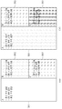
- FIG. 5 is a diagram conceptually illustrating resource allocation information used by an electronic device according to an embodiment of the present specification. Specifically, FIG. 5 shows content areas of a plurality of applications displayed on a display of an electronic device and resource allocation information therefor.
- content for a plurality of applications may be displayed on the display.
- Contents for a plurality of applications may be displayed in different areas.
- the content for application A (hereinafter, referred to as the first application) is in the first area 510
- the content for application B (hereinafter, referred to as the second application) is in the second area
- content for application C (hereinafter, referred to as a third application) may be displayed in the third area 530.
- Resource allocation information for each application may be different from each other.
- Resource allocation information is a value (or part, or ratio) allocated for each application to run an application for various resources (e.g., CPU, GPU, display brightness, display resolution, FPS (frame per second)) constituting an electronic device. )
- resources e.g., CPU, GPU, display brightness, display resolution, FPS (frame per second) constituting an electronic device.
- the resource allocation information may mean information on a value designated (or set) to be used for driving a specific application for each resource.
- the resource allocation information may be referred to as configuration information, and the present specification is not limited by such terms.
- the resource allocation information includes a portion of the CPU (central processing unit) used for each application, CPU utilization, CPU usage time, GPU (graphics processing unit) utilization, GPU usage time, FPS (frame per frame). second), resolution, display brightness, and loudness information. A more detailed description of each name will be described later.
- the part in which the CPU is used refers to a part of the plurality of parts used for driving a specific application (eg, a first application, a second application, a third application) when the CPU included in the electronic device is divided into a plurality of parts.
- a specific application eg, a first application, a second application, a third application
- the CPU utilization rate may mean the ratio of the CPU used to drive a specific application among the operations of the entire CPU.
- the use time of the CPU may mean the time that the CPU is used to run a specific application.
- the utilization rate of the GPU may refer to a rate used to run a specific application among the entire operation of the GPU.
- the use time of the GPU may mean the time that the GPU is used to run a specific application.
- the use time of the GPU may mean the time that the CPU is used to run a specific application.
- Frame per second may mean frames per second displayed on a display for displaying content related to a specific application.
- the resolution may mean a degree of how many pixels or dots appear in the content related to a specific application on the display.
- Display brightness may refer to a degree of brightness when content related to a specific application is displayed on the display.
- the display brightness may appear within a range where the maximum brightness is set to 100% and the minimum brightness is set to 0%.
- the display may appear dimming, in which case 0% dimming may correspond to maximum brightness.
- the loudness may mean the loudness of the sound when the content related to a specific application is sound content.
- the loudness of the sound can appear within a range where the maximum is 100 and the minimum is 0.
- Resource allocation information may be classified for each application as shown in FIG. 5. Specifically, 100% of the display brightness is allocated to the driving of the first application (maximum brightness is 100%, minimum brightness is 0%), CPUs 4, 5, 6, and 7 are allocated, and 70% of the GPU may be allocated. . In addition, 700ms of use time of the CPU and GPU may be allocated, respectively.
- 20% of the display brightness is allocated, CPUs 0, 1, and 2 are allocated, and 20% of the GPU may be allocated.
- 100 ms of each CPU and GPU usage time may be allocated.
- a component included in an electronic device refers to a unit that processes at least one function or operation, which may be implemented as hardware or software, or a combination of hardware and software.
- the electronic device 600 may include a display 610, a memory 620, and a control unit 630.
- the display 610 may be implemented by a computing device including a microprocessor, which is the same for the memory 620 and the control unit 630 to be described later.
- the display 610 may display (or display) content corresponding to the application in response to the execution of the application.
- Content corresponding to the application may include various screens provided by the application. If a plurality of applications are executed, the display 610 may display contents of each of the plurality of applications.
- content corresponding to the first application may be displayed on the first area of the display 610, and content corresponding to the second application may be displayed on the second area of the display 610.
- the first area and the second area may be separate areas, but are not limited thereto.
- the size of the display 610 displayed on one surface of the display 610 may be changed according to a control signal.
- the displayed size of the display 610 may be changed based on a control signal related to the size change of the display 610.
- resource allocation information eg, display brightness
- the resource allocation information of the first area may be determined to correspond to the resource allocation information of the second area. have.
- the memory 620 may store resource allocation information related to each of a plurality of applications. For example, as resource allocation information determined for the first application, information on the used part of the CPU, the utilization rate of the GPU, the FPS, and the brightness of the display may be stored, and the first application, which is known for the second application, is described above. It is possible to store information about the resource allocation information for and the used portion of the CPU, the utilization rate of the GPU, FPS, and brightness of the display that are separated from the resource allocation information for
- an allocation portion for the same resource may be different from each other.
- a portion of the CPU used to drive the first application and the portion of the CPU used to drive the second application may be different from each other.
- the FPS related to driving the first application and the FPS related to driving the second application may be different from each other.
- a display brightness of an area in which the content of the first application is displayed may be different from the display brightness of an area in which the content of the second application is displayed.
- the controller 630 may execute a plurality of applications. Specifically, the controller 630 may display content related to each of the plurality of applications through the display 610 in response to obtaining an input for executing the plurality of applications. In this case, content related to each of the plurality of applications may be displayed on different areas of the display 610.
- the controller 630 may check resource allocation information related to each of a plurality of applications. For example, when a plurality of applications includes a first application and a second application, the controller 630 may check resource allocation information related to the first application and resource allocation information related to the second application.
- the resource allocation information may include information on a portion (or ratio) allocated to operate for driving an application for each of various resources constituting the electronic device 600.
- the controller 630 may run a plurality of applications based on the resource allocation information. Specifically, the controller 630 may drive the first application with related resource allocation information and the second application with related resource allocation information.
- resources are differently allocated for each area in which application-related content is displayed, for example, brightness, resolution, or driving speed of the display may be determined independently of each other and may appear differently.
- the brightness of the display may be independently adjusted for each area in which the content is displayed and may appear differently. have.
- the resolution of the display may be independently adjusted for each area in which the content is displayed, resulting in a different display.
- the application driving speed may be different for each area in which the contents are displayed.
- the resource allocation information may be determined for each area in which the application is displayed, for each category related to the application, or for each resource usage information according to past execution of the application.
- the controller 630 may check an area on the display 610 in which the content is displayed when content related to the application is displayed. The controller 630 may check resource allocation information corresponding to the identified region and allocate resources for driving the application accordingly.
- the controller 630 may check a category (eg, a game, a messenger, or a photo) to which the executed application belongs in response to the execution of the application.
- the controller 630 may check resource allocation information corresponding to the identified category and allocate resources for driving the application accordingly.
- a category eg, a game, a messenger, or a photo
- the controller 630 when the resource allocation information is determined for each resource usage information according to the past execution of an application, the controller 630 provides information on a resource that was used more than a specific frequency or more than a specific ratio when the application was executed in the past. You can check.
- the controller 630 may allocate a resource for driving an application based on information on the identified resource. For example, if it is determined that the average of the GPU utilization rate when executing an application in the past is 30% based on resource usage information according to the past execution, the resource may be allocated as 30% to the GPU among resources of the application. For a more detailed description related to this, refer to FIG. 16.
- the resource allocation information may be determined by the user.
- the controller 630 may provide a user with an input window for designating resource allocation information for each application. When a user's input is obtained for the provided input window, the controller 630 may set resource allocation information for the application in response thereto. For a more specific example related to this, refer to FIG. 15.
- the electronic device 600 may further include a battery that supplies power for driving the electronic device 600.
- the controller 630 may check the remaining capacity of the battery. When the remaining capacity is less than or equal to a specific value, the controller 630 may change the resource allocation information of the running application.
- the controller 630 may reduce the brightness of the display to 50% of the current resource allocation value.
- an allocation value for each resource may be specified for each step.
- the resource allocation information of step 1 may mean a step that reflects the initial value as it is, and step 2 operates at 80% of the initial value (e.g., if the initial value of FPS is 10, step 2 is 80 of 10). It can mean the step of 8) being a percentage.
- the controller 630 may adjust the level of the resource allocation information according to the remaining capacity of the battery.
- the controller 630 may receive a user's input for one of contents related to a plurality of applications. For example, the controller 630 may receive a user input for selecting an area in which content related to the first application is displayed. The controller 630 may check an application related to a user's input.
- the controller 630 may set the resource allocation information of the identified application to the first state and the resource allocation information of another application (eg, an unverified application) to the second state.
- another application eg, an unverified application
- the first state may be a state in which each value of the resource allocation information maintains an initial value
- the second state may be a state in which each value of the resource allocation information becomes 80% of the initial value
- the first state may be a state in which each value of the resource allocation information becomes 110% of the initial value
- the second state is a state in which each value of the resource allocation information becomes 80% of the initial value. I can.
- the resources reduced by the second state may be used to implement the first state.
- the user's input may be implemented as various inputs, such as an input based on eye recognition through a sensor, or a physical touch input of the user, and is not limited to the above-described example.
- FIGS. 10 to 13 a more specific example related to the change of resource allocation information according to a user's input for one application may refer to FIGS. 10 to 13.
- the controller 630 may receive inputs for two applications. In this case, the controller 630 may allocate resources according to an initial value of resource allocation information of an application related to the received input.
- inputs for two applications may be, for example, an input for switching two applications.
- the display settings of each of the two applications can be switched (or exchanged).
- an area in which each of the two applications is displayed may be switched.
- FIG. 7 is a flowchart illustrating a flow of each step of a method of controlling an electronic device according to an exemplary embodiment of the present specification. It goes without saying that each step of the method illustrated in FIG. 7 may be performed in a different order as illustrated in the drawings depending on the case. In addition, portions overlapping with the above-described contents in FIG. 6 may be omitted.
- the electronic device may display content corresponding to the first application on the first area of the display (710 ). Specifically, when the first application is executed, the electronic device may display the content of the first application on the first area of the display.
- the first area may be an arbitrary location or a location designated to display content corresponding to the execution of the first application, but is not limited thereto.
- the electronic device may display content corresponding to the second application on the second area of the display (720 ). Specifically, when the second application is executed, the electronic device may display the content of the second application on the second area of the display.
- the second area may be an arbitrary location or a location designated to display content corresponding to the execution of the second application, but is not limited thereto.
- steps 710 and 720 may be executed regardless of the order.
- the display of content related to the first application and the second application may be performed in response to the expansion of the display. A specific example related to this will be described later with reference to FIG. 8.
- the electronic device may check resource allocation information related to the first application and the second application (730 ).
- the resource allocation information is known for each application and may be a value (eg, a CPU utilization rate) for a degree to which a resource (or setting) of an electronic device is allocated for driving an application.
- the resource may be a hardware or software configuration of an electronic device used to execute an application, and may include, for example, a CPU, a GPU, and a display.
- the resource allocation information is a value allocated for each application in order to drive the application, and may include, for example, a utilization rate and a brightness level.
- a resource may be referred to as configuration and resource allocation information may be referred to as configuration information, but the present specification is not limited to these terms.
- the electronic device may check resource allocation information of each of the first application and the second application.
- the electronic device may drive the first application and the second application based on the resource allocation information (operation 740).
- the electronic device may drive the application by allocating resources based on the resource allocation information identified for each application.
- the first application may be driven by distributing 60% of the GPU to driving the first application.
- the electronic device may adjust resource allocation information according to reception of a user's input or a state of a battery. A specific example related to this will be described later with reference to FIGS. 9 to 17.
- FIG. 8 is a diagram conceptually illustrating an example in which content corresponding to a plurality of applications is displayed in an electronic device according to an exemplary embodiment of the present specification.
- the bar content 810 may be executed.
- the bar content 810 may be executed according to a user's input or may be executed in response to satisfaction of a specific condition. For example, when a user's touch input to a predetermined area of the right edge of the display is received, the bar content 810 may be displayed. For another example, when a message is received, the bar content 810 may be displayed.
- the bar content 810 may include an application icon.
- an input for moving the application icon may be received as shown in FIG. 8(b).
- the input for moving the application icon may be, for example, a drag input, but is not limited thereto.
- the application icon may be moved toward the top of the display.
- a second application corresponding to the application icon may be executed, and third content 815 related to the second application may be displayed in an upper area (eg, a second area) of the display as shown in FIG. 8(c).
- the first content 811 and the second content 813 may be moved to and displayed in a lower area (eg, a first area) of the display.
- the display may be expanded as shown in FIG. 8C in response to execution of the second application.
- the size shown on one side of the display may be changed according to the control signal.
- the electronic device may drive the application based on resource allocation information for each application for smoother operation than the application.
- FIG. 9 is a diagram illustrating an example in which resource allocation information for each category of a plurality of applications is determined in an electronic device according to an embodiment of the present specification. Specifically, FIG. 9 shows a case in which resource allocation information is determined for each of three categories.
- each category will be referred to as a first category, a second category, and a third category as general terms.
- Resources that are intensively used for each application category may be different. For example, in the case of an application belonging to the game category, since high-end graphics are required, a higher value of GPU utilization may be required than other applications. For another example, in the case of a content reproduction application, since the content must be seamlessly reproduced, a higher FPS value may be required than other applications.
- resource allocation information of each of a plurality of categories may be determined differently by reflecting characteristics of each category as illustrated.
- a category for each application installed in the electronic device may be determined by a user or by identification of the electronic device, and resource allocation information of an application may be determined corresponding to resource allocation information of a category to which the application belongs.
- the'A application' may be identified as a game category, and in this case, the resource allocation information of the'A application' may be designated to correspond to the resource allocation information of the game category.
- resource allocation information may be determined for each area. For example, resource allocation information may be determined for each area corresponding to each category of FIG. 9 (eg, a first category, a second category, and a third category). In this case, when the application is executed, an area in which content related to the application is displayed may be checked, and the application may be driven based on resource allocation information corresponding to the identified area.
- category of FIG. 9 e.g, a first category, a second category, and a third category.
- the first application may be driven based on resource allocation information of the first category.
- FIG. 10 is a diagram illustrating an example of entering a power saving mode in an electronic device according to an embodiment of the present specification.
- 10A illustrates an example in which resource allocation information of other applications is adjusted when the remaining capacity of the battery is less than or equal to a first value and a user's input is applied to the'A' application.
- contents related to each of the'A' application (hereinafter, referred to as the first application), the'B' application (hereinafter, referred to as the second application), and the'C' application (hereinafter, referred to as the third application) are It can be displayed in different areas.
- content related to the first application may be displayed in the first area 1011
- content related to the second application may be displayed in the second area 1012
- content related to the third application may be displayed in the third area 1013.
- the 10A illustrates a state in which a user input is applied to the first application while each application is driven according to designated resource allocation information.
- the user input may be, for example, a touch input or a focus input checked based on movement of the pupil.
- the electronic device may adjust a step of resource allocation information related to driving of the second application and the third application.
- the level of the resource allocation information is that the resource allocation value is reduced so that power lower than the set value is consumed, and may be divided according to the degree of reduction. For example, when the initial set value is 100%, the first step may be reduced by 100%, and the second step may be reduced by 20%.
- resource allocation information related to the first application is not controlled and may be driven according to an existing resource allocation value.
- the lowering adjustment may be performed by one step, and in the case of the third application, the lowering adjustment may be performed by the second step.
- Step adjustment for each application may be preset. For example, when the step is adjusted by a user input, the second application may be preset to be lowered by one step and the third application may be lowered by two steps.
- the step adjustment of the resource allocation information may be performed when a specific condition (eg, the remaining capacity is less than the first value) is satisfied by additionally considering the remaining capacity of the battery. For example, when the remaining capacity of the battery is 15% or less and a user input is applied to the first application, step adjustment may be performed as shown in FIG. 10A.
- a specific condition eg, the remaining capacity is less than the first value
- step adjustment may be performed differently for each application as shown in FIG. 10(a), but is not limited thereto.
- step adjustment of the third application may also be lowered by one step like the second application.
- an additional step adjustment may be made according to the value of the remaining capacity.
- the level of resource allocation information for each of the first application, the second application, and the third application may be adjusted. That is, for each application, the resource allocation value can be adjusted down by one step.
- the amount of energy consumption of the electronic device may be reduced and the electronic device may be driven for a longer time.
- FIG. 11 is a diagram illustrating an example in which an input is applied to at least two of a plurality of applications of an electronic device according to an exemplary embodiment of the present specification.
- 11(a) and 11(b) illustrate a case in which contents related to each of the first application, the second application, and the third application are displayed in different areas as shown in FIG. 10(a) or 10(b). do.
- FIG. 11A shows an example in which a user input is applied to a first application and a second application among three applications.
- the level of resource allocation information related to driving of the third application is adjusted, and resource allocation information related to driving of the first application and the second application may maintain an existing value.
- the remaining capacity of the battery may be additionally considered.
- FIG. 11(a) shows an example in which a user input is applied to the first application and the second application, and the remaining capacity of the battery is less than or equal to the first value. Can be.
- the user input may be made for an application (eg, a third application) requiring step adjustment, and the present specification is not limited thereto.
- user input can be implemented in various ways. For example, it may include a touch, long touch, or knock-on input.
- the input for the first application (eg, touch) and the input for the second application (eg, long touch) may be different, but the present specification is not limited thereto.
- FIG. 10B shows a case in which the level of resource allocation information of all running applications is adjusted based on the remaining capacity of the battery being less than the second value.
- the second value may be a value smaller than the above-described first value. That is, when the remaining capacity of the battery is less than the second value, it may mean that the power saving mode is required.
- the steps of resource allocation information of the first application and the second application may be adjusted in the same manner as the resource allocation information of the third application.
- FIG. 12 is a diagram illustrating an example in which an input to one of a plurality of applications of an electronic device is changed according to an exemplary embodiment of the present specification.
- the user input can be moved. Specifically, after a user input is applied to the application'A', the user input may move to the application'B'. In this case, resource allocation information may be adjusted in response to the movement of the user input.
- resource allocation information of other applications other than the'A' application may be adjusted. Thereafter, when a user input is applied to the'B' application, resource allocation information of the other applications except for the'B' application may be adjusted.
- the resource allocation information of the second application when the resource allocation information of the second application is decreased based on a user input, the resource allocation information may increase in response to a value reduced in the second application for the first application to which the input is applied. For example, when the CPU utilization rate of the second application is reduced from 40% to 30%, the CPU utilization rate of the first application may increase from 50% to 60%.
- the step adjustment of the resource allocation information may correspond to the adjustment to the power saving mode or the ultra power saving mode.
- the first-level lowering adjustment may correspond to setting the driving of the application to the power saving mode
- the second-level lowering adjustment may correspond to setting the driving of the corresponding application to the ultra-power saving mode.
- FIG. 13 is a diagram illustrating an example in which an input of an electronic device moves according to an exemplary embodiment of the present specification. Specifically, FIG. 13 shows an example in which resource allocation information is adjusted according to time when a user input moves.
- user input may be sequentially moved. For example, as shown, the user input is first applied to application'A' at 12:00, and moves to application'B' at 12:02, and then moves back to application'C' at 12:04. I can. At 12:08, the user input can be moved back to the'A' application.
- resource allocation information may be maintained at a specific ratio (eg, 60%). If the existing input is released according to the movement of the user input, the resource allocation information of the application in which the user input is released may decrease at a specific rate interval over time.
- the resource allocation information of the'A' application is 60%, but when the user input moves to another application (for example,'B' application), the'A' application is Resource allocation information may decrease by 5%.
- FIG. 14 is a diagram illustrating an example in which a switch input of an electronic device is applied according to an exemplary embodiment of the present specification.
- an input for switching applications in the first area 1410 and the second area 1420 is received while different applications are displayed in the first area 1410 and the second area 1420, respectively. Can be.
- resource allocation of an application related to the third area 1430 may be adjusted.
- resources of an application related to the third area 1430 may be allocated at a level of 60% of the resource allocation information.
- the resource allocation amount reduced in relation to the third region 1430 may be used to drive applications of the first region 1410 and the second region 1420.
- FIG. 15 is a diagram conceptually illustrating a resource allocation information setting window of an electronic device according to an embodiment of the present specification. Specifically, FIG. 15 shows an example of a user interface for receiving a user input when resource allocation information is determined by a user input.
- resource allocation information may be determined through content provided for each application. Specifically, resource allocation information may be set by entering the setting window of each of the'A' application, the'B' application, and the'C' application.
- the resource allocation information may be determined by selecting a degree of filling in a bar shape based on a user input. For example, when the entire bar corresponding to the brightness is filled, the brightness may be determined to be maximum, that is, 100%.
- the system resource may be a CPU or GPU, and a utilization rate of the CPU or GPU may be determined through a bar.
- content for determining resource allocation information for each application may be displayed in a specific area irrespective of the area in which the application is displayed.
- the user input related to the determination of resource allocation information is not limited to the example shown in FIG. 15 and may be implemented in various forms such as a method in which the user directly inputs text.
- 16 is a diagram illustrating an example of setting resource allocation information based on past use of an application in an electronic device according to an embodiment of the present specification.
- FIG. 16(a) conceptually shows a process of acquiring resource usage information according to past executions for each of the applications'A, B, and C'.
- resources eg, CPU, GPU
- FIG. 16A resources (eg, CPU, GPU) of an electronic device may be used to drive each of the applications “A, B, and C”.
- the resource usage information of the electronic device may be checked at specific time intervals or in real time by the'estimator'. This process may be continuously repeated, and based on this, resource use information according to past executions of each application may be accumulated.
- the electronic device may determine appropriate resource allocation information for each application based on the resource use information.
- 16(b) shows an example of resource allocation information determined based on this.
- the CPU is intensively used to drive the'A' application
- the GPU is intensively used to drive the'B' application
- the'C' application is driven. It can be seen that there are no intensively used resources.
- resource allocation information in driving the'A' application, may be determined by increasing the CPU utilization rate to a specific value (eg, 70%) or more.
- resource allocation information when running the'B' application, may be determined by increasing the GPU utilization rate to a specific value (eg, 60%) or more. It is possible to make resource allocation evenly (or evenly) without being biased toward driving the'C' application.
- 17 is a diagram illustrating an example of setting resource allocation information for each application group of an electronic device according to an embodiment of the present specification.
- different application groups may include execution information of different applications.
- the execution information may include information on at least one of an application to be executed, a region in which content related to the application is displayed, and resource allocation information for each application.
- APP set 1 three applications may be a group displayed as shown in FIG. 17(a).
- two applications may be a group displayed as shown in FIG. 17(b).
- a specific application group eg, APP set 1, APP set 2
- an application corresponding to the selected group is executed, and contents related to the application may be displayed according to the designated split screen.
- the application group may be created by the user's selection. In this case, the applications frequently used by the user and the arrangement of such applications are applied to the group, so that the user can use the electronic device more conveniently.
- Combinations of each block of the block diagram attached to the present specification and each step of the flowchart may be performed by computer program instructions. Since these computer program instructions can be mounted on the processor of a general-purpose computer, special purpose computer or other programmable data processing equipment, the instructions executed by the processor of the computer or other programmable data processing equipment are displayed in each block or flowchart of the block diagram. Each step creates a means to perform the functions described.
- These computer program instructions can also be stored in computer-usable or computer-readable memory that can be directed to a computer or other programmable data processing equipment to implement a function in a particular way, so that the computer-usable or computer-readable memory It is also possible to produce an article of manufacture in which the instructions stored in the block diagram contain instruction means for performing the functions described in each block of the block diagram or each step of the flowchart. Since computer program instructions can also be mounted on a computer or other programmable data processing equipment, a series of operating steps are performed on a computer or other programmable data processing equipment to create a computer-executable process to create a computer or other programmable data processing equipment. It is also possible for the instructions to perform the processing equipment to provide steps for executing the functions described in each block of the block diagram and each step of the flowchart.
- each block or each step may represent a module, segment, or part of code that contains one or more executable instructions for executing the specified logical function(s).
- functions mentioned in blocks or steps may occur out of order.
- two blocks or steps shown in succession may in fact be performed substantially simultaneously, or the blocks or steps may sometimes be performed in the reverse order depending on the corresponding function.
Abstract
La présente invention concerne, selon un de ses modes de réalisation, un procédé de commande de dispositif électronique pouvant comporter les étapes consistant à : afficher, sur une première région d'un affichage, un contenu correspondant à une première application ; afficher, sur une seconde région de l'affichage, un contenu correspondant à une seconde application ; vérifier des informations d'attribution de ressources liées à la première application et à la seconde application ; et piloter la première application et la seconde application sur la base des informations vérifiées d'attribution de ressources.
Priority Applications (2)
| Application Number | Priority Date | Filing Date | Title |
|---|---|---|---|
| PCT/KR2019/014359 WO2021085663A1 (fr) | 2019-10-29 | 2019-10-29 | Dispositif électronique pour pilotage d'application, et son procédé de commande |
| US16/727,828 US11340959B2 (en) | 2019-10-29 | 2019-12-26 | Electronic apparatus for running application and control method thereof |
Applications Claiming Priority (1)
| Application Number | Priority Date | Filing Date | Title |
|---|---|---|---|
| PCT/KR2019/014359 WO2021085663A1 (fr) | 2019-10-29 | 2019-10-29 | Dispositif électronique pour pilotage d'application, et son procédé de commande |
Publications (1)
| Publication Number | Publication Date |
|---|---|
| WO2021085663A1 true WO2021085663A1 (fr) | 2021-05-06 |
Family
ID=75586091
Family Applications (1)
| Application Number | Title | Priority Date | Filing Date |
|---|---|---|---|
| PCT/KR2019/014359 WO2021085663A1 (fr) | 2019-10-29 | 2019-10-29 | Dispositif électronique pour pilotage d'application, et son procédé de commande |
Country Status (2)
| Country | Link |
|---|---|
| US (1) | US11340959B2 (fr) |
| WO (1) | WO2021085663A1 (fr) |
Families Citing this family (2)
| Publication number | Priority date | Publication date | Assignee | Title |
|---|---|---|---|---|
| CN110634408B (zh) * | 2019-09-27 | 2021-08-03 | 武汉华星光电半导体显示技术有限公司 | 显示模组以及显示装置 |
| WO2021132743A1 (fr) * | 2019-12-23 | 2021-07-01 | 엘지전자 주식회사 | Dispositif électronique permettant d'afficher un contenu portant sur une application et son procédé de commande |
Citations (6)
| Publication number | Priority date | Publication date | Assignee | Title |
|---|---|---|---|---|
| KR20040051580A (ko) * | 1998-05-28 | 2004-06-18 | 마츠시타 덴끼 산교 가부시키가이샤 | 표시제어장치 및 방법 |
| JP2005174201A (ja) * | 2003-12-15 | 2005-06-30 | Hitachi Ltd | リソース割り当てシステム、方法及びプログラム |
| US20100131957A1 (en) * | 2007-04-13 | 2010-05-27 | Nobuharu Kami | Virtual computer system and its optimization method |
| US9513696B2 (en) * | 2012-03-08 | 2016-12-06 | Hewlett-Packard Development Company, L.P. | Migrating applications across a group of personal mobile devices based on battery usage |
| US20170345399A1 (en) * | 2016-05-31 | 2017-11-30 | Mediatek Inc. | Method for performing display control of an electronic device in response to a user activity, and associated apparatus |
| KR102006419B1 (ko) * | 2012-10-18 | 2019-08-01 | 어드밴스드 마이크로 디바이시즈, 인코포레이티드 | 미디어 하드웨어 자원 할당 |
Family Cites Families (12)
| Publication number | Priority date | Publication date | Assignee | Title |
|---|---|---|---|---|
| JP2003162355A (ja) * | 2001-11-26 | 2003-06-06 | Sony Corp | タスクの表示切り替え方法及び携帯機器及び携帯通信機器 |
| JP2004233845A (ja) * | 2003-01-31 | 2004-08-19 | Toshiba Corp | 情報処理装置および表示輝度制御方法 |
| US9122518B2 (en) * | 2005-08-11 | 2015-09-01 | Pantech Co., Ltd. | Method for selecting and controlling second work process during first work process in multitasking mobile terminal |
| JP5157717B2 (ja) * | 2008-07-28 | 2013-03-06 | 富士通株式会社 | 仮想バッテリを備えた仮想マシンシステムおよび仮想バッテリを備えた仮想マシンシステム用プログラム |
| KR101957173B1 (ko) * | 2012-09-24 | 2019-03-12 | 삼성전자 주식회사 | 터치 디바이스에서 멀티윈도우 제공 방법 및 장치 |
| KR20150025613A (ko) * | 2013-08-29 | 2015-03-11 | 삼성전자주식회사 | 애플리케이션의 관련 정보를 표시하는 전자 장치 및 방법 |
| US10402034B2 (en) * | 2014-04-02 | 2019-09-03 | Microsoft Technology Licensing, Llc | Adaptive user interface pane manager |
| US9703445B2 (en) * | 2014-05-07 | 2017-07-11 | International Business Machines Corporation | Dynamic, optimized placement of computer-based windows |
| US20160132301A1 (en) * | 2014-11-06 | 2016-05-12 | Microsoft Technology Licensing, Llc | Programmatic user interface generation based on display size |
| US10223228B2 (en) * | 2016-08-12 | 2019-03-05 | International Business Machines Corporation | Resolving application multitasking degradation |
| US10721179B2 (en) * | 2017-11-21 | 2020-07-21 | International Business Machines Corporation | Adaptive resource allocation operations based on historical data in a distributed computing environment |
| KR102255469B1 (ko) * | 2018-03-06 | 2021-05-24 | 삼성전자주식회사 | 플렉서블한 디스플레이를 포함하는 전자 장치 및 그 동작 방법 |
-
2019
- 2019-10-29 WO PCT/KR2019/014359 patent/WO2021085663A1/fr active Application Filing
- 2019-12-26 US US16/727,828 patent/US11340959B2/en active Active
Patent Citations (6)
| Publication number | Priority date | Publication date | Assignee | Title |
|---|---|---|---|---|
| KR20040051580A (ko) * | 1998-05-28 | 2004-06-18 | 마츠시타 덴끼 산교 가부시키가이샤 | 표시제어장치 및 방법 |
| JP2005174201A (ja) * | 2003-12-15 | 2005-06-30 | Hitachi Ltd | リソース割り当てシステム、方法及びプログラム |
| US20100131957A1 (en) * | 2007-04-13 | 2010-05-27 | Nobuharu Kami | Virtual computer system and its optimization method |
| US9513696B2 (en) * | 2012-03-08 | 2016-12-06 | Hewlett-Packard Development Company, L.P. | Migrating applications across a group of personal mobile devices based on battery usage |
| KR102006419B1 (ko) * | 2012-10-18 | 2019-08-01 | 어드밴스드 마이크로 디바이시즈, 인코포레이티드 | 미디어 하드웨어 자원 할당 |
| US20170345399A1 (en) * | 2016-05-31 | 2017-11-30 | Mediatek Inc. | Method for performing display control of an electronic device in response to a user activity, and associated apparatus |
Also Published As
| Publication number | Publication date |
|---|---|
| US20210124625A1 (en) | 2021-04-29 |
| US11340959B2 (en) | 2022-05-24 |
Similar Documents
| Publication | Publication Date | Title |
|---|---|---|
| WO2021100932A1 (fr) | Dispositif électronique de commande de taille d'écran d'affichage et procédé de commande associé | |
| WO2021112272A1 (fr) | Dispositif électronique de fourniture de contenu et son procédé de commande | |
| WO2021085658A1 (fr) | Dispositif électronique comprenant un dispositif d'affichage de taille variable et procédé de commande associé | |
| WO2017065365A1 (fr) | Terminal mobile et procédé de commande de celui-ci | |
| WO2015190666A1 (fr) | Terminal mobile et son procédé de commande | |
| WO2017007060A1 (fr) | Terminal mobile | |
| WO2021045275A1 (fr) | Terminal mobile et procédé de commande associé | |
| WO2015046636A1 (fr) | Terminal mobile et son procédé de commande | |
| WO2017094926A1 (fr) | Dispositif terminal et procédé de commande | |
| WO2016182108A1 (fr) | Terminal mobile et son procédé de commande | |
| WO2015178561A1 (fr) | Terminal mobile et son procédé de réglage dynamique de trame | |
| WO2017057799A1 (fr) | Terminal mobile pour commander une résolution dynamique et son procédé de commande | |
| WO2021107225A1 (fr) | Dispositif électronique de commande de taille d'affichage et procédé de commande de celui-ci | |
| WO2021149840A1 (fr) | Dispositif électronique d'affichage de contenu et procédé de commande associé | |
| WO2015194797A1 (fr) | Terminal mobile et son procédé de commande | |
| WO2015194723A1 (fr) | Terminal mobile et procédé de commande correspondant | |
| WO2018043853A1 (fr) | Dispositif de capture d'images hdr et procédé de commande associé | |
| WO2017171161A1 (fr) | Terminal mobile | |
| WO2016195193A1 (fr) | Terminal mobile et son procédé de commande | |
| WO2017094972A1 (fr) | Ensemble de charge de cadre électronique et procédé de charge de cadre électronique | |
| WO2021137318A1 (fr) | Terminal mobile et son procédé de commande | |
| WO2016068394A1 (fr) | Terminal mobile et son procédé de commande | |
| WO2016200005A1 (fr) | Terminal mobile et procédé d'utilisation de son affichage | |
| WO2021085663A1 (fr) | Dispositif électronique pour pilotage d'application, et son procédé de commande | |
| WO2016035955A1 (fr) | Terminal mobile et procédé de commande associé |
Legal Events
| Date | Code | Title | Description |
|---|---|---|---|
| 121 | Ep: the epo has been informed by wipo that ep was designated in this application |
Ref document number: 19950776 Country of ref document: EP Kind code of ref document: A1 |
|
| NENP | Non-entry into the national phase |
Ref country code: DE |
|
| 122 | Ep: pct application non-entry in european phase |
Ref document number: 19950776 Country of ref document: EP Kind code of ref document: A1 |