WO2021084604A1 - Folding cart - Google Patents
Folding cart Download PDFInfo
- Publication number
- WO2021084604A1 WO2021084604A1 PCT/JP2019/042314 JP2019042314W WO2021084604A1 WO 2021084604 A1 WO2021084604 A1 WO 2021084604A1 JP 2019042314 W JP2019042314 W JP 2019042314W WO 2021084604 A1 WO2021084604 A1 WO 2021084604A1
- Authority
- WO
- WIPO (PCT)
- Prior art keywords
- leg
- handle
- horizontal
- brace
- structures
- Prior art date
Links
Images


Classifications
-
- B—PERFORMING OPERATIONS; TRANSPORTING
- B62—LAND VEHICLES FOR TRAVELLING OTHERWISE THAN ON RAILS
- B62B—HAND-PROPELLED VEHICLES, e.g. HAND CARTS OR PERAMBULATORS; SLEDGES
- B62B3/00—Hand carts having more than one axis carrying transport wheels; Steering devices therefor; Equipment therefor
- B62B3/02—Hand carts having more than one axis carrying transport wheels; Steering devices therefor; Equipment therefor involving parts being adjustable, collapsible, attachable, detachable or convertible
-
- B—PERFORMING OPERATIONS; TRANSPORTING
- B62—LAND VEHICLES FOR TRAVELLING OTHERWISE THAN ON RAILS
- B62B—HAND-PROPELLED VEHICLES, e.g. HAND CARTS OR PERAMBULATORS; SLEDGES
- B62B5/00—Accessories or details specially adapted for hand carts
- B62B5/06—Hand moving equipment, e.g. handle bars
Definitions
- the present invention relates to a foldable trolley.
- the dolly can be folded and unfolded without disassembling or reassembling the components, but the lock mechanism that locks the foldable dolly in the unfolded state is the upper end of the frame away from the operation handle.
- the foldable bogie has many moving parts, and it is desired to provide a brace member on the bogie frame in order to secure the rigidity in the deployed state, but this becomes a problem when the bogie frame is folded.
- the present invention provides a foldable trolley capable of facilitating folding and unfolding of a trolley frame provided with a brace member.
- the first aspect of the present invention is to connect a pair of vertical structures (5) facing each other in the first horizontal direction and the pair of vertical structures (5).
- a plurality of horizontal structures (10) supporting the shelf board (9) and a trolley frame (2) are provided, and each of the plurality of horizontal structures (10) is centered in the first direction.
- a movable portion (13) that can be bent is provided in the portion, and the plurality of horizontal structures (10) can be bent in interlocking with each other via an interlocking member (18). From the deployed state (P1) in which the shelf board (9) is horizontally supported by the plurality of horizontal structures (10), the plurality of horizontal structures (10) are interlocked and the movable portion (13) moves upward.
- the pair of vertical structures (5) can be bent so as to be in a folded state (P2) in which the pair of vertical structures (5) are brought close to each other, and the trolley frame (2) is horizontal perpendicular to the first direction.
- a streak member (20) for holding the unfolded state (P1) and a handle (30) gripped by the user when folding the trolley frame (2) are provided.
- the streak member (20) includes an upper portion of one vertical structure (5) and a lower portion of the other vertical structure (5) in the pair of vertical structures (5).
- the streak member (20) is provided with a bendable streak movable portion (21) in the middle of the streak member (20) in the length direction, and the handle (30) is the handle (30).
- the second handle (32) is fixed to the first divided body (10a) of the operating horizontal structure (10c), and when the trolley frame (2) is folded, together with the second handle (32).
- the first split body (10a) can be operated so as to be close to the first handle (31).
- At least one of the second handle (32) and the operating horizontal structure (10c) is brought into contact with the brace member (20) when the bogie frame (2) is folded, and the brace member (20) is attached to the brace member (20). It is provided with a bending contact portion (35).
- the brace member can be extended by a one-action operation, and the bogie frame can be brought into the expanded state.
- the second aspect of the present invention is the first aspect when the carriage frame (2) is held under the carriage frame (2) and the carriage frame (2) is in the folded state (P2) in the first aspect.
- a leg member (40) extending outward from the pair of vertical structures (5) in the direction and touching or approaching the ground (F) is provided.
- the leg member (40) is placed on the other side of the carriage frame (2) in the second direction opposite to the handle (30). It is provided. According to this configuration, since the leg member is provided on the side opposite to the handle in the second direction, it is possible to prevent the leg member from interfering with the foot space of the user who grips the handle. Although the leg member is located far from the user who grips the handle, it can be avoided that the folding work of the carriage becomes complicated by automatically deploying the leg member according to the folding of the carriage frame.
- the leg member (40) extends in the first direction and can be bent in the middle of the leg member (40) in the length direction.
- the leg member (40) is provided with a movable leg (41), and the end (40c) in the length direction can be grounded or approached to the ground (F) by bending the leg movable portion (41).
- the foldable trolley (1) is a leg locking device (50) that holds the leg movable portion (41) in a bent state while the leg member (40) is in contact with or close to the ground (F). It has. According to this configuration, the leg locking device locks the operation of the leg movable portion while the leg member is in contact with or close to the ground, so that the trolley in the folded state can be reliably supported by the leg member.
- the leg locking device (50) has a lock operation unit (50) on the handle (30) side in the second direction of the carriage frame (2). 51b) is provided. According to this configuration, the user who holds the handle can easily operate the lock operation of the leg lock device, and the leg member can be easily locked and unlocked. In particular, the effect is high when the leg member is provided on the side opposite to the handle.
- a sixth aspect of the present invention is, in the fourth or fifth aspect, the leg extending downward from at least one of the plurality of lateral structures (10) and moving upward with the movable portion (13).
- a leg interlocking member (45) is provided so that the movable portion (41) is pulled upward to bring the end portion (40c) of the leg member (40) into contact with or close to the ground (F).
- the leg members are interlocked to bring the end portion to the ground or close to the ground, so that the dolly in the folded state is easily and surely supported. be able to.
- a seventh aspect of the present invention is that in any one of the first to sixth aspects, the carriage frame (2) is folded on one side of the carriage frame (2) in the second direction.
- the lock device (15) held in (P2) is provided. According to this configuration, since the lock device is provided on the same side as the handle on the bogie frame, when the user performs the folding work and the unfolding work of the bogie frame by using the handle, the locked and unlocked state in the folded state by the lock device. Can be made easier.
- An eighth aspect of the present invention is, in any one of the first to seventh aspects, an urging member that urges the brace member (20) so as to extend the flexion of the brace movable portion (21). (25) is provided.
- an urging member that urges the brace member (20) so as to extend the flexion of the brace movable portion (21). (25) is provided.
- a ninth aspect of the present invention includes a cover member (26) that covers the periphery of the brace movable portion (21) in any one of the first to eighth aspects. According to this configuration, it is possible to suppress contact and biting of foreign matter during operation of the brace movable portion.
- a tenth aspect of the present invention is, in any one of the first to ninth aspects, the contact portion (35) abuts on the brace member (20) and is rollable (37). ) Is provided. According to this configuration, the roller at the contact portion bends the brace member while rolling on the brace member, so that the brace member can be smoothly bent.
- (C) shows when the bogie frame is in the folded state and the brace member is completely bent.
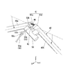
- It is a perspective view which shows the leg member of the foldable trolley (a) is the trolley frame in the expanded state and the leg member is retracted, (b) is the trolley frame in the middle of folding, and the leg member is in the middle of extension.
- (c) indicates when the bogie frame is in the folded state and the leg members are fully extended.
- It is a perspective view which shows the leg lock device of the foldable trolley (a) shows the whole leg lock device, (b) shows the periphery of an operation member, and (c) shows the periphery of a lock member. It is a perspective view around the leg movable part of the foldable carriage.
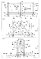
- the foldable trolley 1 (hereinafter, may be simply referred to as trolley 1) shown in FIGS. 1 to 3 carries a plurality of small assembly units assembled on the small assembly line to the main line, for example, in a completed vehicle assembly line of an automobile. Used for Since the dolly stock area of the small group line is limited, the following effects can be obtained by folding the dolly 1 (see FIG. 3) so that it can be stored compactly. That is, it is possible to reduce the man-hours by eliminating the need to put the trolley 1 in and out of a separate storage place, and to make it easier to adjust the number of trolley 1 even when the number of production increases or decreases.
- the carriage 1 is provided with a carriage frame 2 that partitions a rectangular parallelepiped-shaped component storage space and supports a plurality of shelves 9 in this space.
- a carriage frame 2 that partitions a rectangular parallelepiped-shaped component storage space and supports a plurality of shelves 9 in this space.
- each configuration in the unfolded state in which the shelf board 9 is horizontal will be described.
- the XYZ Cartesian coordinate system is set and each configuration is described.
- the direction along the arrow X is referred to as the left-right direction (vehicle width direction)
- the direction along the arrow Y is referred to as the front-rear direction (vehicle depth direction)
- the direction along the arrow Z is referred to as the vertical direction (vehicle vertical direction).
- the vertical direction is the normal direction (vertical direction) of the horizontal floor surface F on which the carriage 1 is placed. Viewing from the width of the dolly is called side view.
- the bogie frame 2 is configured by combining, for example, a frame member made of a hollow extruded material made of aluminum alloy and a hinge mechanism that rotatably connects a plurality of frame members at the center of an axis along the left-right direction.
- the dolly frame 2 is made of a light aluminum material and constitutes a parallel link mechanism that can be easily unfolded and folded.
- the carriage frame 2 includes a pair of vertical structures 5 facing each other in the front-rear direction, and a plurality of horizontal structures 10 connecting between the pair of vertical structures 5.
- the pair of vertical structures 5 have a symmetrical structure in the front-rear direction.
- Each vertical structure 5 includes a pair of columns 6 extending in the vertical direction at both ends in the left-right direction, and a plurality of left and right horizontal members 7 extending between the pair of columns 6.
- the left and right horizontal members 7 are provided in four upper and lower stages at a substantially equal pitch, for example.
- a caster 6a that allows the carriage 1 to move is attached to the lower end of each column 6.
- each of the left and right horizontal members 7 are connected to the support column 6 via an end rotation mechanism 8 having a coaxial rotation axis.
- Each of the left and right horizontal members 7 is arranged at the same height as each of the plurality of horizontal structures 10.
- Each left and right horizontal member 7 rotatably supports the corresponding horizontal structure 10 with respect to the support column 6. It can be said that each left and right horizontal member 7 is a part of the corresponding horizontal structure 10.
- the plurality of horizontal structures 10 have a structure common to each other.
- Each horizontal structure 10 includes a pair of front-rear horizontal members 11 extending in the front-rear direction at both ends in the left-right direction, and a plurality of intermediate horizontal members 12 extending between the pair of front-rear horizontal members 11. ..
- the plurality of horizontal structures 10 are provided in four upper and lower stages at a height corresponding to each of the plurality of left and right horizontal members 7 of the vertical structure 5.
- Each of the plurality of horizontal structures 10 horizontally supports the shelf board 9. For convenience of illustration, the bottom shelf plate 9 is not shown.
- the plurality of horizontal structures 10 may be referred to as first to fourth horizontal structures 101 to 104 in order from the upper side.
- the first horizontal structure 101 connects the upper ends of the pair of columns 6, and the fourth horizontal structure 104 connects the lower ends of the pair of columns 6.
- the second horizontal structure 102 and the third horizontal structure 103 connect between the upper and lower intermediate portions of the pair of columns 6, respectively.
- Each of the plurality of horizontal structures 10 is provided with a bendable movable portion 13 at the central portion in the front-rear direction.
- the movable portion 13 is provided at the central portion in the front-rear direction of each of the pair of front-rear horizontal members 11.
- the movable portion 13 can bend the horizontal structure 10 (each front and rear horizontal member 11) into an upwardly convex chevron shape.
- Each horizontal structure 10 has a movable portion 13 in the front-rear direction, and has a first divided body 10a on one side in the front-rear direction (the base end side of the arrow Y in the figure (hereinafter referred to as the rear side)) and the front-rear direction.
- Each front and rear horizontal member 11 and each shelf board 9 are also divided in the front-rear direction in accordance with the division of each horizontal structure 10.
- the outer end portion of the first divided body 10a in the front-rear direction is connected to the fixing vertical structure 5a described later in the pair of vertical structures 5.
- the outer end portion of the second split body 10b in the front-rear direction is connected to the moving vertical structure 5b on the opposite side of the fixing vertical structure 5a.
- the trolley frame 2 bends the plurality of horizontal structures 10 and the shelf boards 9 into an upwardly convex chevron shape from the unfolded state P1 (see FIGS. 1 and 2) in which the plurality of horizontal structures 10 and the shelf boards 9 are horizontally arranged. It is possible to bring the pair of vertical structures 5 closer to each other in the front-rear direction to a folded state P2 (see FIG. 3).
- the plurality of horizontal structures 10 can be bent by interlocking with each other via an interlocking member 18 extending in the vertical direction.
- the interlocking members 18 are provided on both sides of the carriage frame 2 in the front-rear direction.
- a caster 18a is attached to the lower end of the interlocking member 18.
- the casters 18a move upward together with the interlocking member 18 and separate from the floor surface F.
- the casters 18a are grounded when the carriage frame 2 is deployed, and are maintained in a state in which the horizontal structure 10 extends linearly in the front-rear direction (a state in which the shelf plate 9 is in a horizontal posture).
- the interlocking member 18 and the casters 18a are arranged so as to be offset inward in the left-right direction from the left-right outer end (position where the support column 6 and the brace member 20 are located) of the bogie frame 2. This prevents the casters 18a from interfering with the two divided bodies 10a and 10b of the lowermost horizontal structure 10 and the brace member 20 when the carriage frame 2 is folded.
- the dolly frame 2 has a brace member 20 for holding the unfolded state P1 on one side in the left-right direction (the tip side of the arrow X in the figure (hereinafter referred to as the left side)) and a user when folding the dolly frame 2. It is provided with a handle 30 for gripping.
- the brace member 20 In the unfolded state P1, the brace member 20 is vertically aligned with the upper portion of one of the pair of vertical structures 5 (for example, the rear side) and the other of the pair of vertical structures 5 (for example, the front side). It is arranged so as to extend diagonally across the lower part of the structure 5.
- the brace member 20 is arranged at a position where it overlaps with the support column 6 in the left-right direction.
- the brace member 20 includes a brace movable portion 21 that can be bent in the middle in the length direction thereof.
- the brace movable portion 21 is provided at a portion near the upper end of the brace member 20.
- the brace movable portion 21 is provided at a portion near the upper end of the brace member 20, but may be provided at an arbitrary portion between both ends of the brace member 20 in the length direction.
- the brace movable portion 21 can bend the brace member 20 into an upwardly convex chevron shape.
- the brace member 20 is a relatively short first brace split 20a connected to the upper part of one (rear side) vertical structure 5 with the brace movable portion 21 sandwiched in the length direction, and the other (front side). It is divided into a relatively long second brace split 20b, which is connected to the lower part on the vertical structure 5 side.
- the handle 30 is a first handle 31 fixed to one of the pair of vertical structures 5 (for example, the rear side, the side to which the upper end portion of the streak member 20 is connected).
- the horizontal structure 10 (third horizontal structure 103) is located at a height below the first handle 31 and away from the floor surface F in the unfolded state P1 of the carriage frame 2. ) Is provided with a second handle 32.
- the vertical structure 5 to which the first handle 31 is fixed may be referred to as a fixing vertical structure 5a
- the horizontal structure 10 to which the second handle 32 is fixed may be referred to as an operating horizontal structure 10c.
- the second handle 32 is fixed to the first divided body 10a (divided body of the front-rear horizontal member 11) of the operating horizontal structure 10c.
- the second handle 32 includes a lever member 32a extending in the front-rear direction, and a support member 32b extending over the lever member 32a and the first divided body 10a.
- the lever member 32a is arranged at a position separated from the lateral structure 10c for operation in the left-right direction.
- the lever member 32a is shorter than the total width of the carriage frame 2 in the front-rear direction, and extends to both sides across the central position of the carriage frame 2 in the front-rear direction.
- the latter half of the lever member 32a is supported and fixed to the operation horizontal structure 10c via a pair of support members 32b.
- the user When the user folds the trolley frame 2 having the handle 30, the user first stands on the left side of the trolley frame 2, holds the first handle 31 with the left hand, and shows the right hand (only the right hand is indicated by reference numeral H). ) Holds the second handle 32. Next, the user rotates the second handle 32 so as to lift it with his right hand, and operates the second handle 32 so as to bring it closer to the first handle 31. Then, the first divided body 10a of the operating horizontal structure 10c also rotates integrally with the second handle 32, and the plurality of horizontal structures 10 are bent in conjunction with each other accordingly. As a result, the carriage frame 2 and thus the carriage 1 are folded so that the pair of vertical structures 5 come close to each other.
- the moving vertical structure 5b moves backward and approaches the fixing vertical structure 5a to which the first handle 31 is fixed.
- the casters 6a of the fixing vertical structure 5a are locked from turning around the vertical axis, for example, and their movement in the front-rear direction is restricted. As a result, the moving vertical structure 5b is moved backward to make it easier to approach the fixed vertical structure 5a.
- a caster 6a capable of switching between locking and unlocking may be used for the caster 6a of the fixing vertical structure 5a, and the caster 6a may be used for the caster 6a of the moving vertical structure 5b. ..
- At least one of the second handle 32 and the operating horizontal structure 10c is brought into contact with the brace member 20 (second brace split body 20b) when the bogie frame 2 is folded, and the brace member 20 is attached.
- a contact portion 35 for bending is provided.
- the contact portion 35 includes, for example, a contact member 36 fixed to the inside of the second handle 32 in the left-right direction.
- the second handle 32 and the operating horizontal structure 10c rotate upward about the rotation axis of the rear end of the operating horizontal structure 10c, and the contact member 36 rotates during this rotation.
- the locus R1 intersects the brace member 20 in a lateral view.
- the abutting member 36 abuts on the brace member 20 from below, giving the brace member 20 a trigger for bending.
- the pair of vertical structures 5 have started approaching, and a load in the buckling direction is applied to the brace member 20. Therefore, the abutting member 36 only abuts on the brace member 20 to cause the initial bending motion, and then the brace member 20 is automatically folded so as to increase the bending angle.
- the contact portion 35 may be composed of, for example, a support member 32b on the center side in the front-rear direction of the carriage frame 2 in the second handle 32.
- the contact portion 35 may include a roller 37 that can contact and roll in the middle of the brace member 20 in the length direction.
- the roller 37 may be made of, for example, a resin material softer than the brace member 20.
- the brace movable portion 21 is provided with an urging member 25 that applies an urging force so as to extend the flexion of the brace movable portion 21.
- the urging member 25 is composed of, for example, a tension coil spring, and is arranged so that the expansion / contraction direction is substantially orthogonal to the length direction of the brace member 20.
- the coil end on one side in the expansion / contraction direction is locked to the end of the rotation shaft of the movable portion 21, and the coil end on the other side in the expansion / contraction direction is arranged diagonally downward and locked to the support column 6. ..
- the brace member 20 in the bent state is likely to return to the linear state.
- the urging member 25 facilitates the brace member 20 to return to its brace mode.
- the periphery of the brace movable portion 21 and the urging member 25 is covered with the cover member 26.
- the cover member 26 covers the periphery of the brace movable portion 21 that bends and stretches and the brace member 25 that expands and contracts, thereby suppressing contact and biting of foreign matter with the brace movable portion 21 and the brace member 25.
- the cover member 26 hides the mechanical parts to improve the appearance.
- the cover member 26 may be transparent or translucent.
- the uppermost horizontal structure 10 (first horizontal structure 101) in which the upper ends of the brace member 20 are close to each other is fixed to the first split body 11a (split body of the front and rear horizontal members 11) of the horizontal structure 10.
- a regulating member 27 is provided so as to project outward in the left-right direction. The regulating member 27 prevents the brace member 20 from being excessively bent when the carriage frame 2 is folded, and assists the brace member 20 to be reliably extended when the carriage frame 2 is deployed.
- a lock device 15 for holding the carriage frame 2 in the folded state P2 is provided on one side (left side, the same side as the handle 30) of the carriage frame 2 in the left-right direction.
- the lock device 15 is configured by using, for example, an air coupler 16.
- the air coupler 16 is arranged so that the axial direction is along the front-rear direction.
- the plug 16a of the air coupler 16 is fixed to the fixing vertical structure 5a via the support member 17a.
- the socket 16b of the air coupler 16 is fixed to the moving vertical structure 5b via the support member 17b.
- the air coupler 16 can be automatically locked in response to an operation of folding the carriage frame 2 (an operation in which a pair of vertical structures 5 approach each other in the front-rear direction).
- the air coupler 16 is arranged at a height close to the second handle 32 (below the second handle 32 in the embodiment) when the carriage frame 2 is folded.
- the hand H holding the second handle 32 assists the connection of the air coupler 16, and when the dolly frame 2 is unfolded, the unlock sleeve of the socket 16b (not shown). It is possible to quickly grasp the second handle 32 with the hand H that operates the above and assist the deployment.
- a leg member 40 extending outward in the front-rear direction from the pair of vertical structures 5 is provided.
- the leg member 40 is provided on the other side (right side, opposite to the handle 30) in the left-right direction of the carriage frame 2.
- the leg member 40 includes a leg movable portion 41 that extends in the front-rear direction and can be bent in the middle in the length direction thereof.
- the leg movable portion 41 is provided at the central portion of the leg member 40 in the length direction (left-right direction). The leg movable portion 41 can bend the leg member 40 into an upwardly convex chevron shape.
- the leg member 40 sandwiches the leg movable portion 41 in the length direction, and has a first leg split body 40a on one side (rear side) in the front-rear direction and a second leg split body 40b on the other side (front side) in the front-rear direction. And, it is divided into.
- the leg member 40 has a length equivalent to the total width of the carriage frame 2 in the unfolded state P1 in the front-rear direction, and does not project outward in the front-rear direction of each vertical structure 5 in the unfolded state P1 (FIG. 7A). reference).
- the leg members 40 project outward in the front-rear direction relative to the pair of vertical structures 5 that are close to each other (see FIGS. 7 (b) and 7 (c)).
- the leg movable portion 41 bends and changes into a chevron shape, so that both end portions 40c in the length direction are displaced downward so that the leg member 40 can touch the floor surface F.
- the leg movable portion 41 is in a state where both end portions 40c of the leg member 40 are in contact with or close to the floor surface F.
- a leg lock device 50 is provided to hold the leg lock device 50 in a bent state.
- the leg locking device 50 is located in the left-right direction of the trolley frame 2 at a position offset to one side (left side, same side as the handle 30) in the left-right direction and one side (for example, the side of the vertical structure for movement 5b) from the center position in the front-rear direction.
- An operating member 51 that is supported so as to be strokeable, and a lock member 53 that is supported so that the carriage frame 2 can be stroked in the left-right direction on the other side (right side, opposite to the handle 30) in the left-right direction and at the center position in the front-rear direction. It includes a relay rod 55 that spans the operation member 51 and the lock member 53.
- the operation member 51 is inserted and supported in the support member 52 fixed to the left and right horizontal members 7 at the bottom of the fixing vertical structure 5a so as to be strokeable in the front-rear direction.
- the operating member 51 has a rod portion 51a that is linearly formed along the left-right direction and is supported by the support member 52, a spherical knob portion 51b provided on the lateral side of the rod portion 51a in the left-right direction, and a rod portion 51a in the left-right direction. It is provided with a circular ring portion 51c provided on the inside.
- the lock member 53 is inserted into, for example, a support member 54 fixed to one of the first leg split body 40a and the second leg split body 40b (the second leg split body 40b in the figure) so as to be strokeable in the front-rear direction. It is supported.
- the lock member 53 has a rod portion 54a that is linearly formed along the left-right direction and is supported by the support member 54, a lock pin portion 53b provided on the outside in the left-right direction of the rod portion 54a, and the inside of the rod portion 54a in the left-right direction. It is provided with a circular ring portion 53c provided.
- the lock pin portion 53b can be inserted and removed between a pair of hinge members 41a and 41b that rotate relative to each other via a rotation shaft 42 in the leg movable portion 41 when the leg movable portion 41 bends and changes into a chevron shape. is there.
- the lock pin portion 53b is inserted between the pair of hinge members 41a and 41b, the leg movable portion 41 and thus the leg member 40 are locked in a bent state.
- both end portions 40c of the leg member 40 are maintained in a state of being in contact with or close to the floor surface F, and the trolley 1 in the folded state P2 is suppressed from falling.
- the relay rod 55 has a linear main body portion 55a extending in an inclined direction in the left-right direction in the unfolded state P1 of the bogie frame 2, and a first circle provided at an end portion on the left side (operation member 51 side) of the main body portion 55a.
- a ring portion 55b and a second round ring portion 55c provided at an end on the right side (lock member 53 side) of the main body portion 55a are provided.
- the first round ring portion 55b is oscillatedly connected to the round ring portion 51c of the operating member 51.
- the second circular ring portion 55c is entangled with the circular ring portion 53c of the lock member 53 and is swingably connected.
- the lock member 53 cannot be inserted into the leg movable portion 41.
- Both end portions 40c of the leg member 40 are inserted and supported in the leg insertion portion 43 swingably suspended from the left and right horizontal members 7 at the lowermost stage so as to be strokeable in the front-rear direction.
- Both ends 40c of the leg member 40 are prevented from coming off from the leg insertion portion 43 by, for example, increasing the diameter of the end cap 44a.
- the relay rod 55 is arranged obliquely with respect to the front-rear direction, and the knob portion 51b of the operating member 51 is arranged near the left end portion of the vertical structure 5.
- the leg member 40 is outside the leg insertion portion 43 in the front-rear direction.
- the length that extends to increases.
- a pair of stopper members 44b are fixed to the inside of the leg member 40 in the front-rear direction so that the leg member 40 does not extend to one side in the front-rear direction in the folded state P2 of the bogie frame 2. See FIG. 7 (c)).
- the stopper member 44b has an outer diameter that cannot be inserted into the leg insertion portion 43, and is arranged on both sides of the leg movable portion 41 at intervals.
- the stopper member 44b regulates this stroke at an appropriate position even if the leg member 40 makes a stroke that is offset to one side in the front-rear direction when the carriage frame 2 is folded. As a result, in the folded state P2 of the carriage frame 2, the leg members 40 are evenly extended to both sides in the front-rear direction.
- the leg member 40 may be bent in a chevron shape so as to move both end portions 40c downward by its own weight.
- the leg interlocking wire 45 is provided in order to positively bend the leg member 40 (see FIGS. 7 (b) and 7 (c)).
- the leg interlocking wire 45 extends downward from the movable portion 13 of at least one of the plurality of horizontal structures 10 (third horizontal structure 103 in the embodiment) and is connected to the leg movable portion 41.
- the leg interlocking wire 45 has a deflection between the movable portion 13 of the horizontal structure 10 and the leg movable portion 41 of the leg member 40 when the carriage frame 2 is in the deployed state P1 and in the first half when the carriage frame 2 is folded. (See FIG. 7 (b)).
- the leg interlocking wire 45 eliminates bending and pulls up the leg movable portion 41 as the horizontal structure 10 bends and the movable portion 13 moves significantly upward in the latter half of folding the carriage frame 2.
- the leg member 40 can be bent as the carriage frame 2 is folded, and can function as a stand for the carriage 1 in the folded state P2. Since the bending angle of the leg member 40 is small with respect to the bending angle of the horizontal structure 10, the leg member 40 is bent at a shallow angle behind the horizontal structure 10 by utilizing the bending of the leg interlocking wire 45 (cord-shaped member). It is good to let it.
- the leg movable portion 41 or the like may be further provided with an urging member (not shown) for returning the bent leg member 40 to a straight line.
- an urging member not shown
- the leg member 40 quickly returns to a straight line, so that the stroke of the leg member 40 becomes smooth.
- an urging member is provided between the pair of hinge members 41a and 41b of the leg movable portion 41. 46 may be provided.
- the urging member 46 is, for example, a compression coil spring, and is contracted between the pair of hinge members 41a and 41b at a position eccentric from the rotating shaft 42. The urging member 46 makes it easier for the leg member 40 to bend when the carriage frame 2 is folded, and makes it easier to insert the lock pin portion 53b between the pair of hinge members 41a and 41b.
- the lock pin portion 53b can be inserted and removed between the pair of hinge members 41a and 41b of the leg movable portion 41.
- the knob portion 51b of the operating member 51 projects outward in the front-rear direction and the lock pin portion is utilized by utilizing the surplus length of the relay rod 55.
- 53b is inserted into the leg movable portion 41. In this state, the lock pin portion 53b can be inserted into and removed from the leg movable portion 41 by stroking the knob portion 51b in the left-right direction.
- the operation member 51 and the lock member 53 are also offset in the vertical direction.
- the operation member 51 and the relay rod 55 are swingable, and the relay rod 55 and the lock member 53 are swingable, even if the carriage frame 2 is in the folded state P2, the operation member The lock member 53 can be inserted into and detached from the leg movable portion 41 by the stroke operation of 51.
- the brace member 20 having the bendable brace movable portion 21 is brought into contact with the abutting portion 35 from the lateral direction intersecting the longitudinal direction thereof, whereby the bending (folding) of the brace member 20 is assisted. Therefore, the brace member 20 is automatically bent and the pair of vertical structures 5 approach each other by a one-action operation of lifting the second handle 32 and rotating it so as to bring it closer to the first handle 31. It is possible to change the carriage frame 2 to the folded state P2. When the carriage frame 2 is folded, the leg member 40 as a fall prevention stand is automatically deployed in conjunction with the folding, so that the folding operation of the carriage 1 becomes even easier.
- the plurality of bent horizontal structures 10 are in a horizontal state by rotating the second handle 32 downward so as to separate it from the first handle 31.
- the pair of vertical structures 5 are separated from each other.
- the abutting portion 35 is separated from the brace member 20, and the bent brace member 20 can be extended linearly.
- the brace member 20 is passed between the pair of vertical structures 5 by the one-action operation of rotating the second handle 32 so as to be separated from the first handle 31, as in the case of folding. It is possible to change to the expanded state P1.
- the leg member 40 as a fall prevention stand is automatically stored in conjunction with the deployment, so that the deployment work of the carriage 1 becomes even easier.
- the foldable carriage 1 in the above embodiment has a plurality of horizontal structures that connect between the pair of vertical structures 5 and the pair of vertical structures 5 that face each other in the front-rear direction and support the shelf board 9.
- the dolly frame 2 is provided with the structure 10.
- Each of the plurality of horizontal structures 10 is provided with a bendable movable portion 13 at a central portion in the front-rear direction.
- the plurality of horizontal structures 10 can be bent in interlocking with each other via the interlocking member 18.
- the carriage frame 2 is a pair of horizontal structures 10 that are bent so that the movable portion 13 moves upward by interlocking the plurality of horizontal structures 10 from the deployed state P1 in which the shelf board 9 is horizontally supported by the plurality of horizontal structures 10.
- the carriage frame 2 includes a brace member 20 that holds the unfolded state P1 and a handle 30 that the user grips when folding the carriage frame 2 on one side in the left-right direction.
- the brace member 20 is arranged so as to extend over the upper portion of one vertical structure 5 and the lower portion of the other vertical structure 5 in the pair of vertical structures 5 in the deployed state P1.
- the brace member 20 includes a brace movable portion 21 that can be bent in the middle in the length direction thereof.
- the handle 30 is an operation in which the first handle 31 fixed to one of the pair of vertical structures 5 and the plurality of horizontal structures 10 are located below the first handle 31 in the deployed state P1.
- each horizontal structure 10 is positioned on the fixing vertical structure 5a side in the front-rear direction with the movable portion 13 interposed therebetween. It is divided into a first divided body 10a and a second divided body 10b located on the opposite side of the fixing vertical structure 5a in the front-rear direction.
- the second handle 32 is fixed to the first divided body 10a of the horizontal structure for operation 10c, and when the carriage frame 2 is folded, the first divided body 10a is used as the first handle 31 together with the second handle 32. It can be operated to bring it closer.
- At least one of the second handle 32 and the operating horizontal structure 10c is provided with an abutting portion 35 that abuts on the brace member 20 and bends the brace member 20 when the carriage frame 2 is folded.
- a plurality of horizontal structures 10 including the operating horizontal structure 10c are interlocked and bent to bring the pair of vertical structures 5 close to each other. ..
- the brace member 20 can be bent by a one-action operation, and the carriage frame 2 can be brought into the folded state P2.
- the plurality of bent horizontal structures 10 are interlocked and extended to separate the pair of vertical structures 5 from each other.
- the brace member 20 is extended by a one-action operation, and the trolley frame 2 is brought into the deployed state P1. can do.
- the foldable carriage 1 that facilitates folding and unfolding of the carriage frame 2 provided with the brace member 20 without requiring disassembly or reassembly of the component parts.
- the trolley frame 2 when the trolley frame 2 is held under the trolley frame 2 and the trolley frame 2 is in the folded state, it is outside the pair of vertical structures 5 in the first direction.
- a leg member 40 that extends and touches or is in contact with the floor surface F is provided. According to this configuration, even if the trolley frame 2 is folded and the width of the trolley frame 2 is narrowed in the first direction, the leg members 40 are extended to the outside of the pair of vertical structures 5, so that the trolley 1 in the folded state is used. Can be prevented from tipping over in the first direction.
- the leg member 40 By automatically deploying the leg member 40 according to the folding of the carriage frame 2, the work from the folding to the storage of the carriage 1 can be facilitated, and when the carriage 1 is folded, the leg member 40 can be reliably supported by the leg member 40.
- the leg member 40 is provided on the other side of the carriage frame 2 in the second direction opposite to the handle 30. According to this configuration, since the leg member 40 is provided on the side opposite to the handle 30 in the second direction, it is possible to prevent the leg member 40 from interfering with the foot space of the user who grips the handle 30. Although the leg member 40 is located far from the user who grips the handle 30, it can be avoided that the folding work of the carriage 1 becomes complicated by automatically deploying the leg member 40 according to the folding of the carriage frame 2. ..
- the leg member 40 extends in the first direction and includes a leg movable portion 41 that can be bent in the middle of the leg member 40 in the longitudinal direction.
- the leg movable portion 41 By bending the leg movable portion 41, the end portion 40c in the length direction can be grounded or close to the floor surface F, and in the foldable trolley 1, the leg member 40 is grounded or close to the floor surface F.
- the leg locking device 50 is provided to hold the leg movable portion 41 in the bent state in the bent state. According to this configuration, the leg locking device 50 locks the operation of the leg movable portion 41 while the leg member 40 is in contact with or close to the floor surface F, so that the trolley 1 in the folded state is reliably supported by the leg member 40. be able to.
- the leg lock device 50 includes a lock operation unit (knob portion 51b) on the handle 30 side in the second direction of the carriage frame 2. According to this configuration, the user who grips the handle 30 can easily operate the lock operation of the leg lock device 50, and the leg member 40 can be easily locked and unlocked. In particular, when the leg member 40 is provided on the side opposite to the handle 30, the effect is high.
- the leg member 40 extends downward from at least one of the plurality of horizontal structures 10 and pulls up the leg movable portion 41 as the movable portion 13 moves upward.
- a leg interlocking member (leg interlocking wire 45) is provided so that the end portion 40c of the above is grounded or brought close to the floor surface F.
- a lock device 15 for holding the carriage frame 2 in a folded state is provided on one side of the carriage frame 2 in the second direction. According to this configuration, since the lock device 15 is provided on the same side as the handle 30 of the carriage frame 2, when the user performs the folding work and the unfolding work of the carriage frame 2 using the handle 30, the locking device 15 is used for folding. It is possible to easily lock and unlock the state.
- the foldable carriage 1 of the above embodiment includes an urging member 25 that urges the brace member 20 so as to extend the bending of the brace movable portion 21.
- an urging member 25 that urges the brace member 20 so as to extend the bending of the brace movable portion 21.
- the foldable carriage 1 of the above embodiment includes a cover member 26 that covers the periphery of the brace movable portion 21. According to this configuration, it is possible to suppress the contact and biting of foreign matter during the operation of the brace movable portion 21.
- the contact portion 35 includes a roller 37 that can contact the brace member 20 and roll. According to this configuration, the roller 37 of the contact portion 35 bends the brace member 20 while rolling on the brace member 20, so that the brace member 20 can be smoothly bent.
- the present invention is not limited to the above embodiment.
- the pair of vertical structures 5 is not limited to a frame shape, and may include a wall-shaped portion or a plate-shaped portion at least in part.
- the horizontal structure 10 is not limited to the upper and lower four stages, and may include a smaller number or a larger number of horizontal structures 10.
- the configuration in the above embodiment is an example of the present invention, and various modifications can be made without departing from the gist of the present invention, such as replacing the constituent elements of the embodiment with well-known constituent elements.
Abstract
Description
また、台車フレームを折り畳み状態から展開する際には、屈曲していた複数の横構造体が連動して伸長し、一対の縦構造体同士を離間させる。このとき、筋交い部材から当接部が離間して屈曲していた筋交い部材を伸長状態に戻すことで、ワンアクションの操作によって筋交い部材を伸長させ、台車フレームを展開状態とすることができる。
このように、構成部品の分解や再組立を要することなく、筋交い部材を設けた台車フレームの折り畳みおよび展開を容易にした折り畳み式台車を提供することができる。 According to this configuration, when the bogie frame is folded from the unfolded state, a plurality of horizontal structures including the horizontal structure for operation are interlocked and bent, and the pair of vertical structures are brought close to each other. At this time, when the abutting portion abuts on the brace member and bends, the brace member can be bent by a one-action operation, and the bogie frame can be put into a folded state.
Further, when the carriage frame is unfolded from the folded state, a plurality of bent horizontal structures are interlocked and extended to separate the pair of vertical structures from each other. At this time, by returning the brace member, which has been bent away from the brace member, to the extended state, the brace member can be extended by a one-action operation, and the bogie frame can be brought into the expanded state.
As described above, it is possible to provide a foldable carriage that facilitates folding and unfolding of the carriage frame provided with the brace member without requiring disassembly or reassembly of the components.
この構成によれば、台車フレームを折り畳んで第一の方向で台車フレームの幅が狭まっても、一対の縦構造体よりも外側に脚部材を延ばすことで、折り畳み状態の台車が第一の方向で転倒することを抑えることができる。脚部材は、台車フレームの折り畳みに応じて自動で展開させることで、台車の折り畳みから収納までの作業を容易にし、かつ台車の折り畳み時には脚部材で確実に支えることができる。 The second aspect of the present invention is the first aspect when the carriage frame (2) is held under the carriage frame (2) and the carriage frame (2) is in the folded state (P2) in the first aspect. A leg member (40) extending outward from the pair of vertical structures (5) in the direction and touching or approaching the ground (F) is provided.
According to this configuration, even if the dolly frame is folded and the width of the dolly frame is narrowed in the first direction, the dolly in the folded state is in the first direction by extending the leg members to the outside of the pair of vertical structures. It is possible to prevent the vehicle from tipping over. By automatically deploying the leg members according to the folding of the dolly frame, the work from folding to storing the dolly can be facilitated, and the dolly can be reliably supported by the leg members when the dolly is folded.
この構成によれば、第二の方向で取っ手と反対側に脚部材が設けられるので、取っ手を把持する使用者の足元スペースに脚部材が干渉することを抑えることができる。脚部材は、取っ手を把持する使用者から遠い位置にあるが、台車フレームの折り畳みに応じて自動で展開させることで、台車の折り畳み作業が煩雑になることを回避することができる。 In the third aspect of the present invention, in the second aspect, the leg member (40) is placed on the other side of the carriage frame (2) in the second direction opposite to the handle (30). It is provided.
According to this configuration, since the leg member is provided on the side opposite to the handle in the second direction, it is possible to prevent the leg member from interfering with the foot space of the user who grips the handle. Although the leg member is located far from the user who grips the handle, it can be avoided that the folding work of the carriage becomes complicated by automatically deploying the leg member according to the folding of the carriage frame.
この構成によれば、脚部材が地面に接地又は近接した状態で脚ロック装置が脚可動部の作動をロックすることで、折り畳み状態の台車を脚部材で確実に支えることができる。 In a fourth aspect of the present invention, in the second or third aspect, the leg member (40) extends in the first direction and can be bent in the middle of the leg member (40) in the length direction. The leg member (40) is provided with a movable leg (41), and the end (40c) in the length direction can be grounded or approached to the ground (F) by bending the leg movable portion (41). The foldable trolley (1) is a leg locking device (50) that holds the leg movable portion (41) in a bent state while the leg member (40) is in contact with or close to the ground (F). It has.
According to this configuration, the leg locking device locks the operation of the leg movable portion while the leg member is in contact with or close to the ground, so that the trolley in the folded state can be reliably supported by the leg member.
この構成によれば、取っ手を把持する使用者が脚ロック装置のロック操作を容易に操作可能となり、脚部材のロックおよびアンロックを容易に行うことができる。特に、脚部材が取っ手と反対側に設けられる場合はその効果が高い。 In a fifth aspect of the present invention, in the fourth aspect, the leg locking device (50) has a lock operation unit (50) on the handle (30) side in the second direction of the carriage frame (2). 51b) is provided.
According to this configuration, the user who holds the handle can easily operate the lock operation of the leg lock device, and the leg member can be easily locked and unlocked. In particular, the effect is high when the leg member is provided on the side opposite to the handle.
この構成によれば、台車フレームの折り畳み時における横構造体の可動部の上方移動により、脚部材を連動させて端部を地面に接地又は近接させるので、折り畳み状態の台車を容易かつ確実に支えることができる。 A sixth aspect of the present invention is, in the fourth or fifth aspect, the leg extending downward from at least one of the plurality of lateral structures (10) and moving upward with the movable portion (13). A leg interlocking member (45) is provided so that the movable portion (41) is pulled upward to bring the end portion (40c) of the leg member (40) into contact with or close to the ground (F).
According to this configuration, by moving the movable part of the horizontal structure upward when the dolly frame is folded, the leg members are interlocked to bring the end portion to the ground or close to the ground, so that the dolly in the folded state is easily and surely supported. be able to.
この構成によれば、台車フレームにおける取っ手と同側にロック装置を備えるので、使用者が取っ手を用いて台車フレームの折り畳み作業および展開作業を行う際に、ロック装置による折り畳み状態のロックおよびアンロックを行いやすくすることができる。 A seventh aspect of the present invention is that in any one of the first to sixth aspects, the carriage frame (2) is folded on one side of the carriage frame (2) in the second direction. The lock device (15) held in (P2) is provided.
According to this configuration, since the lock device is provided on the same side as the handle on the bogie frame, when the user performs the folding work and the unfolding work of the bogie frame by using the handle, the locked and unlocked state in the folded state by the lock device. Can be made easier.
この構成によれば、台車の折り畳み時に筋交い部材に当接部が当接した際には、付勢部材の付勢力に抗して筋交い部材を屈曲させることができる。台車の展開時に筋交い部材から当接部が離間した際には、付勢部材の付勢力によって筋交い部材を速やかに直線状に伸長させることができる。 An eighth aspect of the present invention is, in any one of the first to seventh aspects, an urging member that urges the brace member (20) so as to extend the flexion of the brace movable portion (21). (25) is provided.
According to this configuration, when the abutting portion comes into contact with the brace member when the carriage is folded, the brace member can be bent against the urging force of the brace member. When the abutting portion is separated from the brace member when the carriage is deployed, the brace member can be quickly and linearly extended by the urging force of the brace member.
この構成によれば、筋交い可動部の作動時における異物の接触や噛み込み等を抑えることができる。 A ninth aspect of the present invention includes a cover member (26) that covers the periphery of the brace movable portion (21) in any one of the first to eighth aspects.
According to this configuration, it is possible to suppress contact and biting of foreign matter during operation of the brace movable portion.
この構成によれば、当接部のローラが筋交い部材に転接しつつ筋交い部材を屈曲させるので、筋交い部材の屈曲をスムーズに行うことができる。 A tenth aspect of the present invention is, in any one of the first to ninth aspects, the contact portion (35) abuts on the brace member (20) and is rollable (37). ) Is provided.
According to this configuration, the roller at the contact portion bends the brace member while rolling on the brace member, so that the brace member can be smoothly bent.
図1~図3に示す折り畳み式台車1(以下、単に台車1ということがある。)は、例えば自動車の完成車組み立てラインにおいて、小組ラインで組み立てた小組ユニットを複数載せてメインラインに搬送するために用いられる。小組ラインの台車ストック面積には限りがあるため、台車1を折り畳んで(図3参照)コンパクトに収納可能とすることで、以下の効果を奏する。すなわち、台車1を別途の収納場所に出し入れすることを不要にして工数削減を図り、かつ生産数の増減にも台車1の数を調整しやすくすることが可能である。 Hereinafter, the foldable trolley of the present embodiment will be described with reference to the drawings.
The foldable trolley 1 (hereinafter, may be simply referred to as trolley 1) shown in FIGS. 1 to 3 carries a plurality of small assembly units assembled on the small assembly line to the main line, for example, in a completed vehicle assembly line of an automobile. Used for Since the dolly stock area of the small group line is limited, the following effects can be obtained by folding the dolly 1 (see FIG. 3) so that it can be stored compactly. That is, it is possible to reduce the man-hours by eliminating the need to put the
本実施形態では、XYZ直交座標系を設定して各構成を説明する。矢印Xに沿う方向を左右方向(台車幅方向)といい、矢印Yに沿う方向を前後方向(台車奥行方向)といい、矢印Zに沿う方向を上下方向(台車上下方向)という。上下方向は、台車1が載置される水平な床面Fの法線方向(鉛直方向)とする。台車幅方向から見ることを側面視という。 The
In this embodiment, the XYZ Cartesian coordinate system is set and each configuration is described. The direction along the arrow X is referred to as the left-right direction (vehicle width direction), the direction along the arrow Y is referred to as the front-rear direction (vehicle depth direction), and the direction along the arrow Z is referred to as the vertical direction (vehicle vertical direction). The vertical direction is the normal direction (vertical direction) of the horizontal floor surface F on which the
一対の縦構造体5は、前後方向で対称の構成を有している。各縦構造体5は、左右方向の両端部でそれぞれ上下方向に延びる一対の支柱6と、一対の支柱6間に渡る複数の左右横架材7と、を備えている。左右横架材7は、例えば略等ピッチで上下四段に設けられている。各支柱6の下端部には、台車1を移動可能とするキャスター6aが取り付けられている。 The
The pair of
筋交い部材20は、展開状態P1において、一対の縦構造体5の内の一方(例えば後側)の縦構造体5の上部と、一対の縦構造体5の内の他方(例えば前側)の縦構造体5の下部と、に渡って斜めに延びるように配置されている。筋交い部材20は、左右方向で支柱6と重なる位置に配置されている。 The
In the unfolded state P1, the
次に、実施形態の作用について説明する。
まず、台車フレーム2を展開状態P1から折り畳む際には、使用者が左手で第一の取っ手31を持ち、右手で第二の取っ手32を持ち上げるように回動させて、第二の取っ手32を第一の取っ手31に近付けるように移動させる。すると、操作用横構造体10cを含む複数の横構造体10が連動して屈曲し、一対の縦構造体5同士を接近させる。このとき、第二の取っ手32とともに操作用横構造体10cの第一の分割体10aが回動するが、これらの少なくとも一方に、筋交い部材20に当接して屈曲させる当接部35が設けられている。屈曲可能な筋交い可動部21を有する筋交い部材20に対し、その長手方向と交差する横方向から当接部35が当接することで、筋交い部材20の屈曲(折り畳み)がアシストされる。このため、第二の取っ手32をもち上げて第一の取っ手31に近付けるように回動させるというワンアクションの操作によって、筋交い部材20を自動的に屈曲させて一対の縦構造体5同士を接近させ、台車フレーム2を折り畳み状態P2に変化させることが可能となる。台車フレーム2の折り畳み時には、これに連動して転倒防止スタンドとしての脚部材40が自動で展開するため、台車1の折り畳み作業がより一層容易になる。 <Action>
Next, the operation of the embodiment will be described.
First, when folding the
また、台車フレーム2を折り畳み状態P2から展開する際には、屈曲していた複数の横構造体10が連動して伸長し、一対の縦構造体5同士を離間させる。このとき、筋交い部材20から当接部35が離間して屈曲していた筋交い部材20を伸長状態に戻すことで、ワンアクションの操作によって筋交い部材20を伸長させ、台車フレーム2を展開状態P1とすることができる。
このように、構成部品の分解や再組立を要することなく、筋交い部材20を設けた台車フレーム2の折り畳みおよび展開を容易にした折り畳み式台車1を提供することができる。 According to this configuration, when the
Further, when the
As described above, it is possible to provide the
この構成によれば、台車フレーム2を折り畳んで第一の方向で台車フレーム2の幅が狭まっても、一対の縦構造体5よりも外側に脚部材40を延ばすことで、折り畳み状態の台車1が第一の方向で転倒することを抑えることができる。脚部材40は、台車フレーム2の折り畳みに応じて自動で展開させることで、台車1の折り畳みから収納までの作業を容易にし、かつ台車1の折り畳み時には脚部材40で確実に支えることができる。 In the
According to this configuration, even if the
この構成によれば、第二の方向で取っ手30と反対側に脚部材40が設けられるので、取っ手30を把持する使用者の足元スペースに脚部材40が干渉することを抑えることができる。脚部材40は、取っ手30を把持する使用者から遠い位置にあるが、台車フレーム2の折り畳みに応じて自動で展開させることで、台車1の折り畳み作業が煩雑になることを回避することができる。 In the
According to this configuration, since the
この構成によれば、脚部材40が床面Fに接地又は近接した状態で脚ロック装置50が脚可動部41の作動をロックすることで、折り畳み状態の台車1を脚部材40で確実に支えることができる。 In the
According to this configuration, the
この構成によれば、取っ手30を把持する使用者が脚ロック装置50のロック操作を容易に操作可能となり、脚部材40のロックおよびアンロックを容易に行うことができる。特に、脚部材40が取っ手30と反対側に設けられる場合はその効果が高い。 In the
According to this configuration, the user who grips the
この構成によれば、台車フレーム2の折り畳み時における横構造体10の可動部13の上方移動により、脚部材40を連動させて端部40cを床面Fに接地又は近接させるので、折り畳み状態の台車1を容易かつ確実に支えることができる。 In the
According to this configuration, by moving the
この構成によれば、台車フレーム2における取っ手30と同側にロック装置15を備えるので、使用者が取っ手30を用いて台車フレーム2の折り畳み作業および展開作業を行う際に、ロック装置15による折り畳み状態のロックおよびアンロックを行いやすくすることができる。 In the
According to this configuration, since the
この構成によれば、台車1の折り畳み時に筋交い部材20に当接部35が当接した際には、付勢部材25の付勢力に抗して筋交い部材20を屈曲させることができる。台車1の展開時に筋交い部材20から当接部35が離間した際には、付勢部材25の付勢力によって筋交い部材20を速やかに直線状に伸長させることができる。 The
According to this configuration, when the abutting
この構成によれば、筋交い可動部21の作動時における異物の接触や噛み込み等を抑えることができる。 The
According to this configuration, it is possible to suppress the contact and biting of foreign matter during the operation of the brace
この構成によれば、当接部35のローラ37が筋交い部材20に転接しつつ筋交い部材20を屈曲させるので、筋交い部材20の屈曲をスムーズに行うことができる。 In the
According to this configuration, the
そして、上記実施形態における構成は本発明の一例であり、実施形態の構成要素を周知の構成要素に置き換える等、本発明の要旨を逸脱しない範囲で種々の変更が可能である。 The present invention is not limited to the above embodiment. For example, the pair of
The configuration in the above embodiment is an example of the present invention, and various modifications can be made without departing from the gist of the present invention, such as replacing the constituent elements of the embodiment with well-known constituent elements.
2 台車フレーム
5 縦構造体
5a 固定用縦構造体
9 棚板
10 横構造体
10a 第一の分割体
10b 第二の分割体
10c 操作用横構造体
13 可動部
15 ロック装置
20 筋交い部材
21 筋交い可動部
25 付勢部材
26 カバー部材
30 取っ手
31 第一の取っ手
32 第二の取っ手
35 当接部
37 ローラ
40 脚部材
40c 端部
41 脚可動部
45 脚連動ワイヤ(脚連動部材)
50 脚ロック装置
51b つまみ部(ロック操作部)
P1 展開状態
P2 折り畳み状態
F 床面(地面)
1 Folding
50
P1 Unfolded state P2 Folded state F Floor (ground)
Claims (10)
- 水平な第一の方向で対向する一対の縦構造体(5)と、前記一対の縦構造体(5)の間を連結するとともに棚板(9)を支持する複数の横構造体(10)と、を備えて台車フレーム(2)を構成し、
前記複数の横構造体(10)の各々は、前記第一の方向の中央部に屈曲可能な可動部(13)を備え、
前記複数の横構造体(10)は、連動部材(18)を介して相互に連動して屈曲可能であり、
前記台車フレーム(2)は、前記複数の横構造体(10)で前記棚板(9)を水平に支持した展開状態(P1)から、前記複数の横構造体(10)を連動させ、前記可動部(13)が上方移動するように屈曲させて前記一対の縦構造体(5)同士を接近させた折り畳み状態(P2)とすることが可能であり、
前記台車フレーム(2)は、前記第一の方向と直交する水平な第二の方向の一側に、前記展開状態(P1)を保持する筋交い部材(20)と、前記台車フレーム(2)を折り畳む際に使用者が把持する取っ手(30)と、を備え、
前記筋交い部材(20)は、前記展開状態(P1)において、前記一対の縦構造体(5)の内の一方の縦構造体(5)の上部と他方の縦構造体(5)の下部とに渡って延びるように配置され、
前記筋交い部材(20)は、前記筋交い部材(20)の長さ方向の途中に屈曲可能な筋交い可動部(21)を備え、
前記取っ手(30)は、前記一対の縦構造体(5)の内の一方に固定される第一の取っ手(31)と、前記複数の横構造体(10)の内、前記展開状態(P1)において前記第一の取っ手(31)よりも下方に位置する操作用横構造体(10c)に固定される第二の取っ手(32)と、を備え、
前記第一の取っ手(31)が固定された前記縦構造体(5)を固定用縦構造体(5a)としたとき、
前記各横構造体(10)は、前記可動部(13)を挟んで、前記第一の方向で前記固定用縦構造体(5a)側に位置する第一の分割体(10a)と、前記第一の方向で前記固定用縦構造体(5a)と反対側に位置する第二の分割体(10b)と、に分割され、
前記第二の取っ手(32)は、前記操作用横構造体(10c)の前記第一の分割体(10a)に固定され、前記台車フレーム(2)の折り畳み時には、前記第二の取っ手(32)とともに前記第一の分割体(10a)を前記第一の取っ手(31)に近付けるように操作可能であり、
前記第二の取っ手(32)および前記操作用横構造体(10c)の少なくとも一方には、前記台車フレーム(2)の折り畳み時に前記筋交い部材(20)に当接して前記筋交い部材(20)を屈曲させる当接部(35)を備えている、折り畳み式台車。 A plurality of horizontal structures (10) that connect between a pair of vertical structures (5) facing each other in the first horizontal direction and the pair of vertical structures (5) and support the shelf board (9). And, to configure the trolley frame (2),
Each of the plurality of transverse structures (10) includes a bendable movable portion (13) at a central portion in the first direction.
The plurality of horizontal structures (10) can be bent by interlocking with each other via the interlocking member (18).
In the carriage frame (2), the plurality of horizontal structures (10) are interlocked with each other from the deployed state (P1) in which the shelf board (9) is horizontally supported by the plurality of horizontal structures (10). It is possible to bend the movable portion (13) so as to move upward so that the pair of vertical structures (5) are brought close to each other in a folded state (P2).
The bogie frame (2) has a brace member (20) holding the unfolded state (P1) and the bogie frame (2) on one side in a horizontal second direction orthogonal to the first direction. With a handle (30) that the user grips when folding,
In the unfolded state (P1), the brace member (20) includes an upper portion of one vertical structure (5) and a lower portion of the other vertical structure (5) in the pair of vertical structures (5). Arranged to extend over
The brace member (20) includes a bendable brace movable portion (21) in the middle of the brace member (20) in the length direction.
The handle (30) is the first handle (31) fixed to one of the pair of vertical structures (5) and the unfolded state (P1) of the plurality of horizontal structures (10). ), The second handle (32) fixed to the operation horizontal structure (10c) located below the first handle (31) is provided.
When the vertical structure (5) to which the first handle (31) is fixed is used as the fixing vertical structure (5a).
Each of the horizontal structures (10) includes a first divided body (10a) located on the fixing vertical structure (5a) side in the first direction with the movable portion (13) interposed therebetween. It is divided into a second divided body (10b) located on the opposite side of the fixing vertical structure (5a) in the first direction.
The second handle (32) is fixed to the first divided body (10a) of the operating horizontal structure (10c), and when the carriage frame (2) is folded, the second handle (32) is used. ), And the first divided body (10a) can be operated so as to approach the first handle (31).
At least one of the second handle (32) and the operating horizontal structure (10c) is brought into contact with the brace member (20) when the bogie frame (2) is folded, and the brace member (20) is attached to the brace member (20). A foldable trolley with a bending contact (35). - 前記台車フレーム(2)の下部に保持され、前記台車フレーム(2)が前記折り畳み状態(P2)となったとき、前記第一の方向で前記一対の縦構造体(5)よりも外側に延びて地面(F)に接地又は近接する脚部材(40)を備えている、請求項1に記載の折り畳み式台車。 It is held under the carriage frame (2), and when the carriage frame (2) is in the folded state (P2), it extends outward from the pair of vertical structures (5) in the first direction. The foldable trolley according to claim 1, further comprising a leg member (40) grounded or close to the ground (F).
- 前記脚部材(40)は、前記台車フレーム(2)における前記第二の方向で前記取っ手(30)とは反対側の他側に設けられている、請求項2に記載の折り畳み式台車。 The foldable carriage according to claim 2, wherein the leg member (40) is provided on the other side of the carriage frame (2) in the second direction opposite to the handle (30).
- 前記脚部材(40)は、前記第一の方向に延び、
前記脚部材(40)の長さ方向の途中に屈曲可能な脚可動部(41)を備え、
前記脚部材(40)は、前記脚可動部(41)が屈曲することで、長さ方向の端部(40c)を地面(F)に接地又は近接可能であり、
当該折り畳み式台車(1)は、前記脚部材(40)が地面(F)に接地又は近接した状態で、前記脚可動部(41)を屈曲状態に保持する脚ロック装置(50)を備えている、請求項2又は3に記載の折り畳み式台車。 The leg member (40) extends in the first direction.
A leg movable portion (41) that can be bent is provided in the middle of the leg member (40) in the length direction.
The leg member (40) can touch or approach the end portion (40c) in the length direction to the ground (F) by bending the leg movable portion (41).
The foldable carriage (1) includes a leg locking device (50) that holds the leg movable portion (41) in a bent state while the leg member (40) is in contact with or close to the ground (F). The foldable trolley according to claim 2 or 3. - 前記脚ロック装置(50)は、前記台車フレーム(2)における前記第二の方向で前記取っ手(30)側に、ロック操作部(51b)を備えている、請求項4に記載の折り畳み式台車。 The foldable carriage according to claim 4, wherein the leg lock device (50) includes a lock operation unit (51b) on the handle (30) side in the second direction of the carriage frame (2). ..
- 前記複数の横構造体(10)の少なくとも一つから下方に延び、前記可動部(13)の上方移動に伴い前記脚可動部(41)を上方に引き上げて、前記脚部材(40)の端部(40c)を地面(F)に接地又は近接させる脚連動部材(45)を備えている、請求項4又は5に記載の折り畳み式台車。 The leg movable portion (41) is pulled upward as the movable portion (13) moves upward, extending downward from at least one of the plurality of lateral structures (10), and the end of the leg member (40). The foldable trolley according to claim 4 or 5, further comprising a leg interlocking member (45) that brings the portion (40c) into contact with or close to the ground (F).
- 前記台車フレーム(2)における前記第二の方向の一側に、前記台車フレーム(2)を折り畳み状態(P2)に保持するロック装置(15)を備えている、請求項1から6の何れか一項に記載の折り畳み式台車。 Any of claims 1 to 6, wherein a lock device (15) for holding the carriage frame (2) in a folded state (P2) is provided on one side of the carriage frame (2) in the second direction. The foldable trolley described in item 1.
- 前記筋交い可動部(21)の屈曲を伸ばすように前記筋交い部材(20)を付勢する付勢部材(25)を備えている、請求項1から7の何れか一項に記載の折り畳み式台車。 The foldable carriage according to any one of claims 1 to 7, further comprising an urging member (25) for urging the brace member (20) so as to extend the bending of the brace movable portion (21). ..
- 前記筋交い可動部(21)の周囲を覆うカバー部材(26)を備えている、請求項1から8の何れか一項に記載の折り畳み式台車。 The foldable carriage according to any one of claims 1 to 8, further comprising a cover member (26) that covers the periphery of the brace movable portion (21).
- 前記当接部(35)は、前記筋交い部材(20)に当接して転動可能なローラ(37)を備えている、請求項1から9の何れか一項に記載の折り畳み式台車。 The foldable carriage according to any one of claims 1 to 9, wherein the contact portion (35) is provided with a roller (37) that is in contact with the brace member (20) and can roll.
Priority Applications (4)
| Application Number | Priority Date | Filing Date | Title |
|---|---|---|---|
| CN201980101649.3A CN114630780B (en) | 2019-10-29 | 2019-10-29 | Folding trolley |
| JP2021553921A JP7208412B2 (en) | 2019-10-29 | 2019-10-29 | folding trolley |
| PCT/JP2019/042314 WO2021084604A1 (en) | 2019-10-29 | 2019-10-29 | Folding cart |
| BR112022007803A BR112022007803A2 (en) | 2019-10-29 | 2019-10-29 | DEMOUNTABLE CART |
Applications Claiming Priority (1)
| Application Number | Priority Date | Filing Date | Title |
|---|---|---|---|
| PCT/JP2019/042314 WO2021084604A1 (en) | 2019-10-29 | 2019-10-29 | Folding cart |
Publications (1)
| Publication Number | Publication Date |
|---|---|
| WO2021084604A1 true WO2021084604A1 (en) | 2021-05-06 |
Family
ID=75715885
Family Applications (1)
| Application Number | Title | Priority Date | Filing Date |
|---|---|---|---|
| PCT/JP2019/042314 WO2021084604A1 (en) | 2019-10-29 | 2019-10-29 | Folding cart |
Country Status (4)
| Country | Link |
|---|---|
| JP (1) | JP7208412B2 (en) |
| CN (1) | CN114630780B (en) |
| BR (1) | BR112022007803A2 (en) |
| WO (1) | WO2021084604A1 (en) |
Citations (3)
| Publication number | Priority date | Publication date | Assignee | Title |
|---|---|---|---|---|
| JPS647835U (en) * | 1987-07-03 | 1989-01-17 | ||
| JP2013023089A (en) * | 2011-07-21 | 2013-02-04 | Houshou Co Ltd | Article loading device |
| JP2016203743A (en) * | 2015-04-20 | 2016-12-08 | 株式会社バリュサポート | Dolly capable of being folded |
Family Cites Families (8)
| Publication number | Priority date | Publication date | Assignee | Title |
|---|---|---|---|---|
| CH687748A5 (en) * | 1994-02-22 | 1997-02-14 | Markus Blaser | Assembly trolley for long components. |
| DE102015000270A1 (en) * | 2014-11-11 | 2016-05-12 | Bow2Go Gmbh | Mobile walking and transport aid device |
| CN105109526A (en) * | 2015-08-27 | 2015-12-02 | 常州天合光能有限公司 | Silicon-wafer transport trolley |
| CN106314496A (en) * | 2016-08-31 | 2017-01-11 | 天津市多彩塑料色母有限公司 | Foldable tool cart |
| DE102016217867B4 (en) * | 2016-09-19 | 2019-04-18 | Bundesdruckerei Gmbh | Luggage transport device and method for transporting a piece of luggage |
| KR200483642Y1 (en) * | 2016-12-21 | 2017-06-09 | 신진숙 | wagon for baby |
| CN106882210A (en) * | 2017-02-22 | 2017-06-23 | 浙江纳斯特日用品有限公司 | A kind of trailing wheel folding pushchair |
| CN108860257A (en) * | 2018-07-27 | 2018-11-23 | 文芙生 | A kind of construction site steel pipe transfer device |
-
2019
- 2019-10-29 CN CN201980101649.3A patent/CN114630780B/en active Active
- 2019-10-29 WO PCT/JP2019/042314 patent/WO2021084604A1/en active Application Filing
- 2019-10-29 JP JP2021553921A patent/JP7208412B2/en active Active
- 2019-10-29 BR BR112022007803A patent/BR112022007803A2/en unknown
Patent Citations (3)
| Publication number | Priority date | Publication date | Assignee | Title |
|---|---|---|---|---|
| JPS647835U (en) * | 1987-07-03 | 1989-01-17 | ||
| JP2013023089A (en) * | 2011-07-21 | 2013-02-04 | Houshou Co Ltd | Article loading device |
| JP2016203743A (en) * | 2015-04-20 | 2016-12-08 | 株式会社バリュサポート | Dolly capable of being folded |
Also Published As
| Publication number | Publication date |
|---|---|
| JP7208412B2 (en) | 2023-01-18 |
| CN114630780B (en) | 2023-08-18 |
| JPWO2021084604A1 (en) | 2021-05-06 |
| BR112022007803A2 (en) | 2022-07-05 |
| CN114630780A (en) | 2022-06-14 |
Similar Documents
| Publication | Publication Date | Title |
|---|---|---|
| KR101083118B1 (en) | Operation lever for vehicle seat | |
| CN102372017B (en) | Stroller with articulating structure | |
| CN101513893B (en) | Convertible hand truck | |
| US9468303B2 (en) | Articulated sofa bed with locking mechanism | |
| US20100007167A1 (en) | Vehicle seat | |
| KR101880988B1 (en) | Transformable Toy Car | |
| EP3095431A1 (en) | Double folding rollator | |
| JP2018532632A (en) | Retractable table | |
| US20070221442A1 (en) | Folding step | |
| CN101378677A (en) | Fold away service tray | |
| US20080157492A1 (en) | Transformable creeper | |
| US8479665B2 (en) | Rear seat table assembly for vehicle | |
| CN108367768A (en) | Wheeled container handle component | |
| CN101722872A (en) | Vehicle seat sliding apparatus | |
| US20220396299A1 (en) | Foldable Trolley | |
| WO2021084604A1 (en) | Folding cart | |
| JP2010537762A (en) | Folding table | |
| US10696198B2 (en) | AV and transport scissor jack rear seat system | |
| JP2751060B2 (en) | Standing device for moving bleachers | |
| JP5713447B2 (en) | Goods loading device | |
| CN110198770B (en) | Deformable toy car | |
| US6158187A (en) | Collapsible structure | |
| JP4386677B2 (en) | table | |
| KR200492853Y1 (en) | Folding cart for carrying | |
| JP4311108B2 (en) | Electric bed |
Legal Events
| Date | Code | Title | Description |
|---|---|---|---|
| 121 | Ep: the epo has been informed by wipo that ep was designated in this application |
Ref document number: 19951207 Country of ref document: EP Kind code of ref document: A1 |
|
| ENP | Entry into the national phase |
Ref document number: 2021553921 Country of ref document: JP Kind code of ref document: A |
|
| NENP | Non-entry into the national phase |
Ref country code: DE |
|
| REG | Reference to national code |
Ref country code: BR Ref legal event code: B01A Ref document number: 112022007803 Country of ref document: BR |
|
| ENP | Entry into the national phase |
Ref document number: 112022007803 Country of ref document: BR Kind code of ref document: A2 Effective date: 20220425 |
|
| 122 | Ep: pct application non-entry in european phase |
Ref document number: 19951207 Country of ref document: EP Kind code of ref document: A1 |