WO2021079474A1 - Security camera device - Google Patents
Security camera device Download PDFInfo
- Publication number
- WO2021079474A1 WO2021079474A1 PCT/JP2019/041773 JP2019041773W WO2021079474A1 WO 2021079474 A1 WO2021079474 A1 WO 2021079474A1 JP 2019041773 W JP2019041773 W JP 2019041773W WO 2021079474 A1 WO2021079474 A1 WO 2021079474A1
- Authority
- WO
- WIPO (PCT)
- Prior art keywords
- security camera
- camera device
- basket
- power
- power supply
- Prior art date
Links
Images


Classifications
-
- B—PERFORMING OPERATIONS; TRANSPORTING
- B66—HOISTING; LIFTING; HAULING
- B66B—ELEVATORS; ESCALATORS OR MOVING WALKWAYS
- B66B11/00—Main component parts of lifts in, or associated with, buildings or other structures
- B66B11/02—Cages, i.e. cars
-
- B—PERFORMING OPERATIONS; TRANSPORTING
- B66—HOISTING; LIFTING; HAULING
- B66B—ELEVATORS; ESCALATORS OR MOVING WALKWAYS
- B66B3/00—Applications of devices for indicating or signalling operating conditions of elevators
Definitions
- the present invention relates to a security camera device that photographs the inside of an elevator basket.
- security camera devices are often installed in newly installed elevators, and elevators equipped with security camera devices at the time of installation tend to be generally limited to expensive elevators.
- a large-scale construction work is required, and the period during which the elevator cannot be used due to the construction work becomes longer, which is convenient for elevator users. There is a problem that is reduced.
- the present invention solves the problems caused by the above-mentioned prior art, it can be easily and quickly installed in the basket without deteriorating the convenience of the elevator user, and contributes to ensuring the safety of the occupants. It is an object of the present invention to provide a security camera device capable of performing.
- the security camera device has a flat plate shape, and one side of the flat plate (hereinafter referred to as “rear surface”) is retrofitted toward the inner wall surface side of the elevator car.
- the security camera device is characterized in that, in the above invention, the power connector is provided on the back surface.
- the security camera device is characterized in that, in the above invention, at least one of a power button and an operation button is provided on the back surface.
- the security camera device is characterized in that, in the above invention, a display screen for displaying an image or a moving image is provided on the front surface.
- the security camera device is provided so that the photographing means is located vertically below the display screen in a state where the photographing means is installed in the basket. It is a feature.
- the security camera device According to the security camera device according to the present invention, it can be easily and quickly installed in the basket without deteriorating the convenience of the elevator user, and can contribute to ensuring the safety of the occupants. Play.
- FIG. 1 is an explanatory view (No. 1) showing an external configuration of a security camera device according to an embodiment of the present invention.
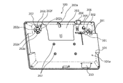
- FIG. 2 is an explanatory view (No. 2) showing an external configuration of the security camera device according to the embodiment of the present invention.
- FIG. 3 is an explanatory view (No. 3) showing an external configuration of the security camera device according to the embodiment of the present invention.
- FIG. 4 is an explanatory view (No. 4) showing an external configuration of the security camera device according to the embodiment of the present invention.
- It is explanatory drawing (the 2) which shows the connection state of an AC power connector and a power supply plug.
- FIG. 1 is an explanatory drawing (the 1) which shows the connection state of an AC power connector and a power supply plug.
- FIG. 7 is an explanatory diagram showing an installation example of the security camera device according to the embodiment of the present invention.
- FIG. 8 is an explanatory diagram showing a display example on the display screen.
- FIG. 9 is a block diagram showing an example of the hardware configuration of the security camera device according to the embodiment of the present invention.
- FIG. 1 shows a front view of the security camera device according to the embodiment of the present invention
- FIG. 2 shows a rear view
- FIG. 3 shows a perspective view from the front side of the security camera device according to the embodiment of the present invention
- FIG. 4 shows a perspective view from the back side.
- the security camera device 100 has a flat plate shape.
- the security camera device 100 includes a housing 101 having a flat rectangular parallelepiped shape, and the housing 101 forms a flat plate shape.
- the security camera device 100 is installed with one surface (hereinafter referred to as “rear surface”) 101a of the flat plate-shaped housing 101 facing the inner wall surface side of the elevator cage (see FIG. 7).
- the security camera device 100 can be retrofitted in the basket.
- a display screen 102 is provided on the surface opposite to the back surface 101a (hereinafter referred to as "front surface 101b").
- the display screen 102 can be realized by, for example, a liquid crystal display (LCD: Liquid Crystal Display), an organic EL (Electro-luminescence) display, a 7-segment display, or the like.
- the front lens 103 is provided on the front 101b.
- the front lens 103 is provided so as to be located vertically below the display screen 102 when it is installed in the basket.
- the front lens 103 together with the front image sensor, constitutes a front camera (see reference numeral 903 in FIG. 9), which is a photographing means according to the present invention.
- the front camera may include one or more lenses between the front lens 103 and the image sensor, a movable mechanism for moving at least one of the plurality of lenses along the optical axis direction, and the like. ..
- the front camera is realized by an AF unit that focuses by a passive method such as contrast AF (AutoFocus) or phase difference AF.
- At least the front lens 103 may be located vertically below the display screen 102, and depending on the shape of the housing 101 and the arrangement of the parts inside the housing 101, the front lens The components other than 103 do not necessarily have to be located below the display screen 102 in the vertical direction.
- a speaker 104 and a status display LED (Light Emitting Diode) 105 are provided on the front 101b.
- the speaker 104 vibrates the diaphragm by an electric signal which is an audio signal to generate sound.
- the speakers 104 are provided on the left and right sides of the display screen 102 (left and right sides when installed in the basket).
- the speaker 104 may be an output terminal that outputs an audio signal, or an external speaker may be connected to the output terminal to generate sound.
- the number of external speakers to be connected may be one or two or more.
- the status display LED 105 indicates the operating state of the security camera device 100. Specifically, the status display LED 105 indicates, for example, a power ON / OFF state, a link-up state, the presence / absence of data transmission / reception, the presence / absence of an error, a warning calling attention, and the like.
- the status display LED 105 is composed of a plurality of LED lamps 105a. Each of the plurality of LED lamps 105a may emit light in a different color, or each of the plurality of LED lamps 105a may appropriately switch a plurality of colors to emit light.
- the status display LED 105 indicates the operating state of the security camera device 100 depending on whether or not each LED lamp 105a is lit and the emission color.
- a power button 201 and an operation button 202 are provided on the back surface 101a. Each time the power button 201 is operated, the power of the security camera device 100 is switched ON / OFF.
- the operation button 202 is composed of a plurality of buttons 202a to 202f.
- buttons 202a and 202b accept, for example, an operation for adjusting the volume of the sound output from the speaker 104.
- the buttons 202c and 202d accept, for example, an operation of selecting a desired operation menu from a plurality of operation menus displayed on the setting screen displayed on the display screen 102 when the security camera device 100 is activated.
- Button 202e accepts the decision of the selected operation menu.
- the button 202e may be operated during the activation of the security camera device 100 to accept an operation of switching the display contents on the display screen 102. Specifically, by operating the button 202e while the security camera device 100 is activated, the display content such as an advertisement can be switched to the setting screen.
- the button 202f is operated while the security camera device 100 is activated to accept the start of shooting. Whether to shoot with the front camera or the rear camera can be selected by operating the buttons 202a to 202e.
- At least one of the power button 201 and the operation button 202 may be provided on the back surface 101a.
- the power button 201 may be provided on the back surface 101a
- the operation button 202 may be provided on the side surface (a surface other than the back surface 101a and the front surface 101b) or the front surface 101b of the housing 101.
- the operation button 202 may be realized by stacking a touch panel on the display screen 102 and using soft keys reproduced by software by the touch panel and the image displayed on the display screen 102.
- the rear surface 101a is provided with a rear lid 203, a rear lens 204, a power switch 205 for a port, an external antenna mounting hole 206, a plurality of screw holes 207, an AC power connector 208, and an AC power cable fixing member 209. ing.
- the back lid 203 is detachably attached to the housing 101.
- the back lid 203 is fixed to the housing 101 using screws or the like.
- the screw for fixing the back lid 203 to the housing 101 it is preferable to use a special screw that cannot be operated with a general-purpose tool. Further, it is preferable that the back cover 203 is provided at a plurality of locations including at least two locations on both sides. The back cover 203 covers the ports and slots provided on the back 101a (both not shown) when attached to the housing 101.
- the port is responsible for inputting / outputting data to / from the outside of the security camera device 100, and can be specifically realized by, for example, a USB Type-A port.
- a plurality of ports may be provided.
- one is used as an interface with an external device such as a remote monitoring device for an elevator, and the other is a USB memory that records (records) the image in the basket taken by the security camera function. It can be used as an interface with the storage device of. As a result, it is possible to record (record) the image in the basket while operating in cooperation with the external device.
- the slot accepts the insertion of an expansion board, a memory card, or the like, and can be specifically realized by, for example, a SIM card slot or a MicroSD card slot.
- the back lid 203 is provided with a slit 203a.
- the cable (see reference numeral 502 in FIGS. 5 and 6) connecting the security camera device 100 and the external device via the port is externally connected from the slit 203a. Can be pulled out to. As a result, the degree of freedom of connection with the external device can be ensured.
- the rear lens 204 together with the rear image sensor, constitutes a rear camera (see reference numeral 905 in FIG. 9).
- the rear camera is used to read the property code (not shown) attached to the elevator to be installed when the security camera device 100 is installed.
- the property code can be realized by, for example, a two-dimensional code attached to the inner wall surface of the elevator car.
- the two-dimensional code may be read by the rear camera only when the security camera device 100 is installed, or may be read periodically after the installation or when predetermined conditions are met.
- the port power switch 205 switches the port power ON / OFF by being operated. As a result, power saving can be achieved by turning off the power when the port is not used.
- a port power switch 205 may be provided for each port. As a result, the power can be switched on / off for each port, and further power saving can be achieved.
- the external antenna mounting hole 206 is used for mounting an external antenna that is separate from the security camera device 100.
- the external antenna mounting hole 206 can be realized by, for example, an F-type connector.
- the F-type connector is connected to a receiving circuit (not shown) inside the housing 101.
- a screw for fixing the security camera device 100 to the inner wall surface of the basket is screwed into the screw hole 207.
- the security camera device 100 may be directly fixed to the inner wall surface of the basket by a screw, or may be fixed to the inner wall surface of the basket via a stay fixed to the inner wall surface of the basket. Good.
- the AC power connector 208 has a power supply plug (see reference numeral 501 in FIGS. 5 and 6) that can be inserted and removed, and receives power supply by inserting the power supply plug connected to the power supply.
- the AC power connector 208 accepts the insertion of a power supply plug included in a device called an AC (Alternating Current) adapter or the like, which is provided with a device that extracts a predetermined DC power from an alternating current input from an AC power supply (commercial power supply).
- the AC power connector 208 realizes the power connector according to the present invention.
- the power supply plug is connected to the AC power supply, and is connected to the main body composed of a transformer circuit, a rectifying circuit, a stabilized power supply circuit, etc. that take out a predetermined DC power from the AC power supply.
- the security camera device 100 By receiving power via the AC adapter, the security camera device 100 itself, which operates using a semiconductor element, can operate even if it is not equipped with a circuit that converts alternating current into direct current. As a result, the weight and cost of the security camera device 100 can be reduced.
- the security camera device 100 itself may include a circuit that converts alternating current into direct current.
- the AC adapter is not limited to the one that is normally connected to the AC power supply, and may include an outlet plug that receives power by being inserted into an outlet.
- the AC power cable fixing member 209 is used to fix the position of the cable continuous with the power supply plug inserted (connected) to the AC power connector 208.
- the AC power cable fixing member 209 has an arc shape in which both ends in the length direction are in contact with the back surface 101a, and a hole is formed by the arcuate inner peripheral surface and the back surface 101a.
- At least one end of the AC power cable fixing member 209 in the length direction is fixed to the back surface 101a.
- the other end of the AC power cable fixing member 209 in the length direction may not be fixed to the back surface 101a or may be separated from the back surface 101a. The method of fixing the cable using the AC power cable fixing member 209 will be described later (see FIGS. 5 and 6).
- Another port is provided at the lower part of the housing 101.
- Another port is responsible for inputting and outputting data to and from the outside of the security camera device 100, and specifically, for example, like the above port, it can be realized by a USB Type-A port.
- Another port is used, for example, when exporting the image data (recorded data of the security camera) taken by the security camera device 100 to the external device.
- the image data can be exported to the external device without removing the security camera device 100 from the inner wall surface of the basket or the back cover 203 from the housing 101. Can be done.
- the housing 101 may be provided with a cover 210 that covers another port.
- the cover 210 may be fixed to the housing 101 using screws or the like.
- As the screw for fixing the cover 210 it is preferable to use a special screw as well as the screw for fixing the back cover 203 described above. As a result, it is possible to prevent the image data from being illegally exported even when the port is provided in the lower part of the housing 101 in order to ensure good operability.
- FIGS. 5 and 6 are explanatory views showing a connection state between the AC power connector 208 and the power supply plug.
- the security camera device 100 can be powered and operated by inserting (connecting) a power supply plug 501 connected to the AC power supply into the AC power supply connector 208. ..
- the cable 502 connected to the power supply plug 501 for example, after inserting (connecting) the power supply plug 501 into the AC power connector 208, consideration is given to preventing disconnection of the cable 502 and preventing interference with surrounding members. Route it to any position. Then, after confirming that the routed cable 502 does not break and that the cable 502 does not interfere with surrounding members, the cable 502 is attached to the AC power cable 502 fixing member 209 using a binding band or the like. Fix it.
- the positional relationship between the AC power connector 208 and the power supply plug 501 is fixed to some extent, the power supply plug 501 is suppressed from freely moving with respect to the AC power connector 208, and the elevator basket moves up and down. It is possible to prevent the power supply from being inadvertently stopped due to vibration or the like. Further, by fixing the position of the cable 502, it is possible to prevent mischief such as the cable 502 hanging down to spoil the aesthetic appearance or pulling the cable 502 to stop the power supply.
- FIG. 7 is an explanatory diagram showing an installation example of the security camera device 100 according to the embodiment of the present invention.
- FIG. 7 shows the inside of the elevator basket.
- the elevator car 701 is provided with a space for the occupant to ride inside, opens and closes the space and the outside, and is provided with a door 702 at the entrance / exit portion where the occupant enters and exits the basket 701.
- a door 702 at the entrance / exit portion where the occupant enters and exits the basket 701.
- an operation panel 703 operated by an occupant on the basket 701 is provided on the inner wall surface of the basket 701.
- the operation panel 703 includes, for example, a group of operation buttons including a destination floor button, a door open / close button, an emergency button, and a display for displaying the floor on which the basket 701 is located.
- the operation panel 703 is an inner surface of the basket 701 and is provided on the same surface as the door 702.
- the security camera device 100 is the same wall surface as the wall surface on which the door 702 and the operation panel 703 are provided, and is installed near the ceiling above the operation panel 703. This assumes that the occupants in the basket 701 generally stand facing the wall surface on the door 702 side.
- the occupant in the basket 701 can display the display.
- the advertisement displayed on the screen 102 can be easily seen. As a result, a high advertising effect can be exhibited through the security camera device 100.
- the security camera device 100 captures the facial expressions of the occupants with, for example, a front camera. By installing the security camera device 100 near the ceiling, the facial expressions of the occupants can be easily photographed by the front camera. In addition, the front camera can capture the facial expressions of the occupants when getting out of the basket 701.
- the security camera device 100 by installing the security camera device 100 near the ceiling, the occupant cannot easily touch the security camera device 100 even if he / she reaches out in a normal state. Therefore, it is possible to prevent the occupant from inadvertently touching, illegally operating, or destroying the security camera device 100.
- the security camera device 100 may be provided on the wall surface (the wall surface on the back side of the basket 701) facing the wall surface on which the door 702 and the operation panel 703 are provided. By providing it on the wall surface on the back side of the basket 701, the occupant can see the security camera device 100 (display screen 102) when entering the basket 701.
- the security camera device 100 on the wall surface on which the door 702 and the operation panel 703 are provided and the wall surface facing the wall surface (the wall surface on the back side of the basket 701), the occupant can be inside the basket 701.
- the security camera device 100 (display screen 102) can be seen when entering and exiting the basket 701.
- the security camera device 100 may be provided on the side wall surface instead of the upper side of the same wall surface as the wall surface on which the door 702 and the operation panel 703 are provided. In this case, it is preferable that the security camera device 100 is provided at an upper position close to the ceiling on the side wall surface of the basket 701. As described above, the security camera device 100 may be installed at any position above the upper end of the door 702 in the basket 701.
- the security camera device 100 can be retrofitted after the elevator is installed.
- the security camera device 100 includes the size of the basket 701 (capacity), the height of the ceiling of the basket 701, the shape of the basket 701 (the floor is square or rectangular, etc.), the type of elevator (see-through type, with or without a mirror on the wall surface). ), The type of outer door (with or without windows), etc. can be taken into consideration when installing in the optimum position. Further, the security camera device 100 may be capable of freely changing its installation position after the security camera device 100 is installed.
- the security camera device 100 can be installed, for example, by screwing it to the wall surface. By screwing the security camera device 100 to the wall surface, it is possible to reliably prevent the device from falling.
- the screwing may be applied not only to the wall surface but also to the ceiling of the basket 701 via a stay or the like.
- the security camera device 100 may be installed by a method other than screwing (for example, using a magnet or the like).
- the basket 701 is provided with a plug socket 704 that accepts the insertion of the outlet plug included in the AC adapter.
- the plug socket 704 constitutes a wiring plug connector together with the outlet plug by inserting the outlet plug provided in the AC adapter.
- an A type plug socket widely used in Japan can be used.
- the plug socket 704 is not limited to the A type. Specifically, for example, a B3 type or C type plug socket widely used in India or Indonesia may be used, or a BF type plug socket widely used in Hong Kong or the like may be used.
- an SE type plug socket widely used in South Korea or the like may be used, or an O type plug socket widely used in Taiwan or the like may be used.
- elevators are installed from various types such as A type, B type, C type, B3 type, BF type, SE type, and O type. It is preferable to use any type of plug socket according to the area where it is used.
- the plug socket 704 is electrically connected to the electric circuit of the board housed in the box on the basket. As a result, power can be supplied to the security camera device 100 via the plug socket 704 and the AC adapter.
- the plug socket 704 is not limited to the one directly connected to the terminal of the electric circuit of the board housed in the box on the basket, and may be connected to the power line connected to the terminal. When connecting the plug socket 704 to such a power line, a branching connector can be provided on the power line, and the plug socket 704 can be connected to the connector.
- the security camera device 100 does not have to make a separate hole for inserting the power supply cable 502 into the basket 701. Can be powered.
- the security camera device 100 can be easily and quickly installed without imposing a burden on the operator, and can be always operated without being stopped due to insufficient power. Further, even when an advertisement or the like is displayed on the display screen, it can be operated stably without being stopped due to insufficient power.
- the work time required for installing the security camera device 100 can be shortened, and the burden on elevator users and workers can be reduced.
- the basket 701 is provided with the plug socket 704, it is not necessary to backfill the through hole for inserting the power supply cable 502 into the basket 701, and the burden on the operator for the removal work is reduced. be able to. Further, it is possible to secure the aesthetic appearance in the basket 701 after the security camera device 100 is removed.
- the plug socket 704 When the plug socket 704 is exposed in the basket 701, it is preferable that the plug socket 704 is arranged at a high position in the basket 701 as shown in FIG. 7. Specifically, as shown in FIG. 7, the plug socket 704 is preferably provided on the side surface or the ceiling surface of the basket 701. By arranging the plug socket 704 exposed in the basket 701 at a high position in the basket 701 in this way, it is possible to prevent water droplets flying from the umbrella or clothes from adhering in rainy weather, and it is possible to prevent electric power theft or children. It can make mischief less likely.
- One plug socket 704 may be provided in one basket 701, or a plurality of plug sockets 704 may be provided in one basket 701.
- the plurality of plug sockets 704 may be arranged side by side or dispersed in a plurality of places.
- the plug socket 704 may be arranged, for example, so that the plug socket 704 is located on the same surface as the inner wall surface (ceiling surface) of the basket 701.
- the basket 701 may be provided with a plug seat, which is not shown, instead of the plug socket 704.
- the plug seat has a function of supplying power supplied from an electric circuit housed in a box on a basket (not shown) to the security camera device 100 connected to the plug seat.
- the resectorable may include wiring for signal transmission in addition to wiring for power supply.
- the resectorable that realizes the plug seat is preferably realized by a hot plug that can be inserted and removed during the operation of the security camera device 100 connected to the resectorable.
- the resectorable that realizes the plug seat may further supply power to the security camera device 100 via a control circuit (not shown).
- the plug seat may be realized by, for example, a USB connector.
- the USB connector as a resectorable that realizes the plug seat can be realized by resectorable of various known USB connectors such as a USB Type-A connector, a Micro USB connector, a Micro USB Type-B connector, and a USB Type-C connector. Can be done.
- the resectorable that realizes the plug seat is not limited to the USB interface connector (resectorable), for example, an IEEE 1394 connector, a PS / 2 connector, a D-Sub connector, a DIN connector, a coaxial connector, and various other known connectors. It may be realized by the connector for communication of.
- One resectorable that realizes the plug seat may be provided in one basket 701, or a plurality of resectors may be provided in one basket 701.
- the number of types of communication I / F connectors may be one type or a plurality of types.
- the resectorable that realizes the plug seat can be arranged, for example, so that the end of the resectorable is located on the same surface as the inner wall surface of the basket 701. Further, the resectorable that realizes the plug seat may, for example, have the end portion of the resectorable protruding from the inner wall surface of the basket 701 to the inside of the basket 701, and is arranged at a position recessed from the inner wall surface of the basket 701. May be good.
- FIG. 8 is an explanatory view showing an example of the appearance of the security camera device 100 according to the embodiment of the present invention.
- the display screen 102 of the security camera device 100 forms a long rectangle in the lateral direction and is surrounded by the housing 101.
- the display screen 102 may be displayed from a plurality of areas (four in this embodiment) such as a security camera image display area 801, a management information display area 802, various information display areas 803, and an advertisement display area (advertisement area) 804. It may be configured. In this way, by dividing the display into four areas and displaying the information, various information can be efficiently transmitted to the occupants.
- a security camera image display area 801, a management information display area 802, and various information display areas 803 are provided in an inverted "L" shape from the upper side to the right side so as to surround the rectangular advertisement display area 804 on the lower left side of the display screen 102.
- the security camera image display area 801 is provided on the left side, and subsequently, the management information display area 802 is provided horizontally. In the security camera image display area 801, the image taken by the front camera may be displayed in real time.
- this management information display area 802 if the message is long, the message is displayed so as to flow from the right side to the left side.
- the management information display area 802 is provided on the upper side of the display screen 102 so that the upper side of the display screen 102 is easily visible to the occupant, and therefore relatively important management information can be reliably transmitted to the occupant.
- various information display areas 803 are provided vertically on the right side surface to display various information to be notified to elevator occupants, such as weather forecasts, traffic information, and news as shown in FIG.
- various information display areas 803 when displaying a large amount of information, it may be displayed so as to flow from the lower side to the upper side.
- the information for the new region when displaying the weather forecast for each region, the information for the new region may be displayed sequentially from the bottom, and the information for the old region may be moved upward and then deleted. On the contrary, it may be displayed so as to flow from the upper side to the lower side. Further, it may be displayed so as to flow to either the left or right.
- the display form can be changed depending on the content of the information to be displayed.
- the management information display area 802 can be lengthened to the right side, and various information display areas 803 can be lengthened to the upper side according to the display situation. Further, depending on the information to be displayed, the management information display area 802 and various information display areas 803 can be used as a series.
- the display screen 102 By laying out the display screen 102 in this way, it is possible to display the advertisement information and at the same time convey other information to the occupant.
- the display screen 102 usually has a layout as shown in FIG. 8, but this layout may be changed depending on the situation. For example, in the event of an emergency such as an elevator failure, the advertising area may be erased to display the required information. Further, as an advertisement display effect, the entire surface of the display screen 102 may be used as an advertisement display.
- FIG. 9 is a block diagram showing an example of the hardware configuration of the security camera device 100 according to the embodiment of the present invention.
- the security camera device 100 includes a CPU 901, a memory 902, a front camera 903, a rear camera 904, a communication interface (I / F) 905, a display screen (display) 102, and a speaker 104.
- a microphone 906, a vibration sensor 907, an illuminance sensor 908, a power button 201, and an operation button 202 are provided.
- Each component 102, 104, 201, 202, 901 to 908 is connected by a bus 900.
- the CPU 901 controls the entire device of the security camera device 100 by executing the program stored in the memory 902.
- the memory 902 can store various information including a program executed by the CPU 901. Further, the memory 902 may store advertisement information displayed on the display screen 102, image data captured by the front camera 903 and the rear camera 904, information regarding the date and time of capture, and the like.
- the memory 902 may be an IC memory, an SSD (Solid State Drive), or the like, in addition to the hard disk memory.
- the memory 902 may be a memory card that can be attached to and detached from the security camera device 100 via a card slot provided in the security camera device 100.
- the function of the memory card can be realized by an IC card such as an SD (Secure Digital) memory card.
- SD Secure Digital
- the memory card may realize its function by an external hard disk, a USB memory, an SSD, or the like.
- the front camera 903 includes a front image sensor, and acquires image information (photographed data) by converting the light received by the front image sensor through the front lens 103 into an electric signal.
- the front camera 903 may capture a still image or may capture a moving image.
- the moving image includes a continuous reproduction of still images taken at predetermined time intervals.
- the image information may be compressed by a standard of a predetermined video / audio data compression method (for example, MPEG (Moving Picture Experts Group) or the like).
- the rear camera 904 includes a rear image sensor, and acquires image information (photographed data) by converting the light received by the rear image sensor through the rear lens 204 into an electric signal.
- the rear camera 904 captures, for example, a still image.
- the image information may be compressed by a standard of a predetermined video / audio data compression method (for example, MPEG (Moving Picture Experts Group) or the like).
- the communication I / F905 is an interface for connecting the security camera device 100 and a network N such as the Internet through a communication line, controls the interface between the network N and the inside of the security camera device 100, and inputs data from an external device. And control the output of data to external devices.
- the CPU 901 may control the communication I / F 905 to acquire advertisement information from an advertisement distribution server or an advertiser's information terminal device (not shown) via the network N. Further, the CPU 901 may control the communication I / F905 to receive advertisement information from an information terminal device such as a smartphone carried by an elevator occupant.
- Communication I / F905 is, for example, a wireless interface using Wi-Fi (registered trademark). Further, the communication I / F905 may be a wireless communication interface such as a mobile phone line (for example, LTE (Long Term Evolution), PHS (Personal Handy-phone System)), or a wired communication such as a modem or a LAN adapter. The interface of the above can be adopted. Further, the elevator may be connected to a network provided for remote monitoring or the like, and information may be transmitted / received via the network. Further, the communication I / F905 may be realized by, for example, a USB interface.
- LTE Long Term Evolution
- PHS Personal Handy-phone System
- the display screen 102 is driven and controlled by the CPU 901 to display an advertisement or the like.
- the display screen 102 may display elevator management information such as a maintenance schedule.
- the management information is appropriately transmitted to the security camera device 100 by, for example, the administrator of the security camera device 100.
- the advertisement information and the management information may include information indicating a period (display start date and time, display end date and time, etc.) to be displayed on the display screen 102.
- the speaker 104 vibrates the diaphragm with an electric signal which is an audio signal to generate sound. Further, the speaker 104 may be an output terminal that outputs an audio signal, and an external speaker 104 may be connected to the output terminal to generate sound.
- the microphone 906 collects the sound in the basket 701.
- the vibration sensor 907 detects the vibration of the basket 701.
- the vibration sensor 907 can be realized by, for example, an acceleration sensor or the like.
- the illuminance sensor 908 detects the illuminance (brightness) in the basket 701.
- the illuminance sensor 908 can be realized by using, for example, a phototransistor or a photodiode.
- the power button 201 or the operation button 202 Each time the power button 201 or the operation button 202 receives an operation, the power button 201 or the operation button 202 outputs a signal corresponding to the received button to the CPU 901.
- the CPU 901 drives and controls each unit based on the signals output from the power button 201 and the operation button 202 to switch the power ON / OFF, adjust the volume of the sound output from the speaker 104, and display the display screen.
- the display content in 102 is switched.
- the security camera device 100 may include a memory card I / F, an input / output device, a power supply control unit, a GPS receiver, and the like.
- the memory card I / F is an interface connected to the security camera device 100 via the card slot.
- the memory card I / F controls the internal interface between the memory card and controls the input of data from the memory card and the output of data to the memory card.
- the input / output device can be realized by, for example, a key or a button for inputting characters, numbers, various instructions, and the like. Further, the input / output device may be realized by a microphone, a display (touch panel), a connection terminal to which another information processing device can be connected, or the like.
- the power supply control unit can be realized by, for example, a voltage adjusting unit (power supply IC or the like) that adjusts the voltage of the AC power supply supplied via the cable 502.
- the power supply control unit may be, for example, a transformer circuit, a rectifying circuit, or a stabilized power supply that extracts a predetermined DC power from an outlet plug, a cable connected to the outlet plug, and an AC power supply supplied via the outlet plug. It may be configured by a circuit or the like.
- the security camera device 100 may further include a battery such as a lithium battery.
- the GPS receiver receives radio waves from three or five GPS satellites, receives radio waves from GPS satellites, and outputs GPS positioning data in order to obtain a geometrical position with the GPS satellites.
- the GPS receiver can grasp the current position of the security camera device 100.
- the security camera device 100 of the embodiment according to the present invention is a security camera device 100 which has a flat plate shape and is retrofitted with the back surface 101a facing the inner wall surface side of the elevator cage 701.
- the security camera device 100 of the embodiment according to the present invention when the security camera device 100 is installed in the basket 701, the security camera device 100 is in a state where the power supply plug 501 is pulled out from the power connector.
- the security camera device 100 can be easily and quickly installed in the basket 701. As a result, it is possible to reduce the burden on the worker who installs the security camera device 100 and the work time required for the installation work, so that the burden on the worker can be reduced.
- the power supply plug 501 is inserted into the AC power connector 208 to stabilize the security camera device 100, which needs to be always activated. Can be powered. As a result, it is possible to eliminate a situation in which shooting is not possible due to insufficient power, to reliably shoot the inside of the basket 701, and to contribute to ensuring the safety of the occupants.
- the time when the elevator cannot be used for work can be shortened by shortening the work time. As a result, it is possible to suppress a decrease in the convenience of the elevator user and ensure the convenience of the user.
- the security camera device 100 of the embodiment according to the present invention can be easily and quickly installed in the basket 701 without deteriorating the convenience of the elevator user, and the safety of the occupant. It can contribute to securing.
- the security camera device 100 of the embodiment according to the present invention is characterized in that the AC power connector 208 is provided on the back surface 101a.
- the security camera device 100 of the embodiment according to the present invention it is possible to make it difficult for the occupant to see the AC power connector 208 when the security camera is installed in the basket 701. As a result, it is possible to prevent the power supply from being stopped due to mischief of the occupant, to reliably photograph the inside of the basket 701, and to contribute to ensuring the safety of the occupant.
- the AC power connector 208 is provided on the side surface of the housing 101, there is a concern that the AC power connector 208 will be easily visible to the occupants and promote mischief. By making it difficult to see, it is possible to surely prevent the power supply from being stopped due to mischief of the occupant, and to secure the aesthetic appearance in the basket 701.
- the security camera device 100 of the embodiment according to the present invention is characterized in that at least one of the power button 201 and the operation button 202 is provided on the back surface 101a.
- the security camera device 100 of the embodiment according to the present invention when the security camera is installed in the basket 701, it is difficult for the occupant to see the operation unit related to the operation of the security camera device 100 such as the power button 201 and the operation button 202. can do. As a result, it is possible to prevent the security camera device 100 from not operating normally due to mischief of the occupant, to reliably photograph the inside of the basket 701, and to contribute to ensuring the safety of the occupant.
- an operation unit related to the operation of the security camera device 100 such as a power button 201 or an operation button 202 is provided on the side surface of the housing 101, the operation unit is easily visible to the occupant, which may facilitate mischief. Although there is concern, by making it difficult for the occupant to see the operation unit, it is possible to reliably prevent the security camera device 100 from malfunctioning due to mischief of the occupant or the like.
- the security camera device 100 of the embodiment according to the present invention is characterized in that a display screen 102 for displaying an image or a moving image is provided on the front surface 101b.
- the security camera device 100 of the embodiment according to the present invention it can be realized by a general-purpose tablet terminal device without separately developing and manufacturing a device dedicated to the elevator. Then, by displaying an image or video that attracts the attention of the occupant on the display screen 102, it is possible to make it easier for the occupant's face to face the security camera device 100. As a result, it is possible to reliably photograph the occupant and contribute to ensuring the safety of the occupant.
- the security camera device 100 of the embodiment according to the present invention when the front camera 903 (at least the front lens 103 constituting the front camera 903) is installed in the basket 701, the security camera device 100 is vertically below the display screen 102.
- the feature is that it is provided so as to be located on the side.
- the front camera 903 (at least the front lens 103 constituting the front camera 903) is located below the display screen 102 in the vertical direction, the front camera The angle of view (shooting range) of the 903 can be easily adjusted. As a result, the inside of the basket 701 can be reliably photographed without being influenced by the shape and size of the basket 701, which can contribute to ensuring the safety of the occupants.
- the security camera device according to the present invention is useful for a security camera device that photographs the inside of a basket for the purpose of crime prevention, and in particular, a security camera device that can further improve the safety of occupants. Are suitable.
- Security camera device 101 Housing 101a Rear 101b Front 102 Display screen 103 Front lens 104 Speaker 105 Status display LED 105a LED lamp 201 Power button 202 Operation button 203 Rear lid 204 Rear camera 205 Port power switch 206 External antenna mounting hole 207 Screw hole 208 AC power connector 209 AC power cable fixing member 210 Cover 701 (elevator) basket 702 (basket) ) Door 703 Operation panel 704 Plug socket 901 CPU 902 Memory 903 Front camera 904 Rear camera 905 Communication I / F 906 Microphone 907 Vibration sensor 908 Illuminance sensor
Abstract
In this security camera device (100) which has a planar plate shape and has a rear surface (101a) post-installed toward an inner wall side of an elevator car, a front camera for imaging the inside of the car is provided on the front surface of the security camera device, and an AC power connector (208), which a power supply plug for supplying power to be supplied for operation of an own device including the front camera can be inserted into or extracted from, is provided, whereby the security camera device 100 can be easily and quickly installed inside the car without degrading the convenience of elevator users, and it is possible to contribute to ensuring the safety of passengers.
Description
この発明は、エレベーターのカゴ内を撮影する防犯カメラ装置に関する。
The present invention relates to a security camera device that photographs the inside of an elevator basket.
エレベーターのカゴ内における防犯を目的として、カゴ内を撮影する防犯カメラ装置を設置したエレベーターが数多く存在する。
There are many elevators equipped with security camera devices that take pictures of the inside of the elevator for the purpose of crime prevention inside the elevator basket.
関連する技術として、具体的には、従来、たとえば、エレベーターのカゴ内に設置されたコンピュータに、エレベーターの乗員に対して画像を表示する第1の処理と、第1の処理によって表示される画像を見ている乗員を撮影する第2の処理と、第2の処理によって撮影された情報を記憶する第3の処理と、を実行させることにより、エレベーターの乗員に対して情報を提供するとともに、エレベーター内で発生するおそれがある犯罪行為などを抑止し、エレベーター内の防犯に寄与するようにした技術があった(たとえば、下記特許文献1を参照。)。
As related technologies, specifically, conventionally, for example, a first process of displaying an image on an elevator occupant on a computer installed in an elevator basket, and an image displayed by the first process. By executing the second process of photographing the occupant watching and the third process of storing the information photographed by the second process, the information is provided to the occupants of the elevator and the information is provided. There was a technique for deterring criminal acts that may occur in an elevator and contributing to crime prevention in the elevator (see, for example, Patent Document 1 below).
しかしながら、防犯カメラ装置は、新規に設置されるエレベーターに備え付けられていることが多く、設置時に防犯カメラ装置を備えているエレベーターは、一般的に、高価なエレベーターに限定される傾向にある。設置時において防犯カメラ装置を備えていないエレベーターに防犯カメラ装置を後付けするためには、大掛かりな工事が必要になり、工事のためにエレベーターを利用できない期間が長くなり、エレベーターの利用者の利便性が低下してしまうという問題がある。
However, security camera devices are often installed in newly installed elevators, and elevators equipped with security camera devices at the time of installation tend to be generally limited to expensive elevators. In order to retrofit an elevator that is not equipped with a security camera device at the time of installation, a large-scale construction work is required, and the period during which the elevator cannot be used due to the construction work becomes longer, which is convenient for elevator users. There is a problem that is reduced.
一方で、費用の面から防犯カメラ装置の設置を先送りすることは、乗員の安全確保が不十分であり好ましくなく、また、エレベーターのカゴ内での犯罪やトラブルが発生しても特定や検証することができず、防犯面において問題がある。
On the other hand, it is not preferable to postpone the installation of the security camera device from the viewpoint of cost because the safety of the occupants is insufficient, and even if a crime or trouble occurs in the elevator basket, it is identified and verified. There is a problem in terms of crime prevention.
この発明は、上述した従来技術による問題点を解消するため、エレベーターの利用者の利便性を低下させることなく、容易かつ速やかにカゴ内に設置することができ、乗員の安全確保に寄与することができる防犯カメラ装置を提供することを目的とする。
Since the present invention solves the problems caused by the above-mentioned prior art, it can be easily and quickly installed in the basket without deteriorating the convenience of the elevator user, and contributes to ensuring the safety of the occupants. It is an object of the present invention to provide a security camera device capable of performing.
上述した課題を解決し、目的を達成するため、この発明にかかる防犯カメラ装置は、平板形状をなし、平板の一面(以下「背面」という)をエレベーターのカゴの内壁面側に向けて後付け設置する防犯カメラ装置であって、前記背面とは反対の面(以下「正面」という)に設けられて前記カゴ内を撮影する撮影手段と、前記撮影手段を含む自装置の駆動に供される電源を供給する電源供給用プラグを挿抜可能な電源コネクタと、を備えることを特徴とする。
In order to solve the above-mentioned problems and achieve the object, the security camera device according to the present invention has a flat plate shape, and one side of the flat plate (hereinafter referred to as "rear surface") is retrofitted toward the inner wall surface side of the elevator car. A security camera device provided on a surface opposite to the back surface (hereinafter referred to as “front”) to photograph the inside of the basket, and a power source used to drive the own device including the photographing means. It is characterized by including a power connector into which a power supply plug for supplying power can be inserted and removed.
また、この発明にかかる防犯カメラ装置は、上記の発明において、前記電源コネクタが、前記背面に設けられていることを特徴とする。
Further, the security camera device according to the present invention is characterized in that, in the above invention, the power connector is provided on the back surface.
また、この発明にかかる防犯カメラ装置は、上記の発明において、前記背面に、電源ボタンおよび操作ボタンの少なくともいずれかが設けられていることを特徴とする。
Further, the security camera device according to the present invention is characterized in that, in the above invention, at least one of a power button and an operation button is provided on the back surface.
また、この発明にかかる防犯カメラ装置は、上記の発明において、前記正面に、画像または映像を表示する表示画面が設けられていることを特徴とする。
Further, the security camera device according to the present invention is characterized in that, in the above invention, a display screen for displaying an image or a moving image is provided on the front surface.
また、この発明にかかる防犯カメラ装置は、上記の発明において、前記撮影手段が、前記カゴ内に設置された状態において、前記表示画面より鉛直方向下側に位置するように設けられていることを特徴とする。
Further, in the above invention, the security camera device according to the present invention is provided so that the photographing means is located vertically below the display screen in a state where the photographing means is installed in the basket. It is a feature.
この発明にかかる防犯カメラ装置によれば、エレベーターの利用者の利便性を低下させることなく、容易かつ速やかにカゴ内に設置することができ、乗員の安全確保に寄与することができるという効果を奏する。
According to the security camera device according to the present invention, it can be easily and quickly installed in the basket without deteriorating the convenience of the elevator user, and can contribute to ensuring the safety of the occupants. Play.
以下に添付図面を参照して、この発明にかかる防犯カメラ装置の好適な実施の形態を詳細に説明する。
A preferred embodiment of the security camera device according to the present invention will be described in detail below with reference to the accompanying drawings.
(防犯カメラ装置の外観構成)
まず、この発明にかかる実施の形態の防犯カメラ装置の外観構成について説明する。図1~図4は、この発明にかかる実施の形態の防犯カメラ装置の外観構成を示す説明図である。図1においてはこの発明にかかる実施の形態の防犯カメラ装置の正面図を示し、図2においては背面図を示している。図3においてはこの発明にかかる実施の形態の防犯カメラ装置の正面側からの斜視図を示し、図4においては背面側からの斜視図を示している。 (Appearance configuration of security camera device)
First, the appearance configuration of the security camera device according to the embodiment of the present invention will be described. 1 to 4 are explanatory views showing an external configuration of a security camera device according to an embodiment of the present invention. FIG. 1 shows a front view of the security camera device according to the embodiment of the present invention, and FIG. 2 shows a rear view. FIG. 3 shows a perspective view from the front side of the security camera device according to the embodiment of the present invention, and FIG. 4 shows a perspective view from the back side.
図1~図4に示すように、この発明にかかる実施の形態の防犯カメラ装置100は、平板形状をなす。具体的に、防犯カメラ装置100は、扁平な長方体形状をなす筐体101を備えており、当該筐体101によって平板形状をなす。防犯カメラ装置100は、平板形状をなす筐体101の一面(以下「背面」という)101aを、エレベーターのカゴの内壁面側に向けた状態で設置される(図7を参照)。防犯カメラ装置100は、カゴ内に後付けすることができる。
As shown in FIGS. 1 to 4, the security camera device 100 according to the embodiment of the present invention has a flat plate shape. Specifically, the security camera device 100 includes a housing 101 having a flat rectangular parallelepiped shape, and the housing 101 forms a flat plate shape. The security camera device 100 is installed with one surface (hereinafter referred to as “rear surface”) 101a of the flat plate-shaped housing 101 facing the inner wall surface side of the elevator cage (see FIG. 7). The security camera device 100 can be retrofitted in the basket.
防犯カメラ装置100の筐体101において、背面101aとは反対の面(以下「正面101b」という)には、表示画面102が設けられている。表示画面102は、たとえば、液晶表示器(LCD:Liquid Crystal Display)、有機EL(Electro-Luminescence)ディスプレイ、7セグメントディスプレイなどによって実現することができる。
In the housing 101 of the security camera device 100, a display screen 102 is provided on the surface opposite to the back surface 101a (hereinafter referred to as "front surface 101b"). The display screen 102 can be realized by, for example, a liquid crystal display (LCD: Liquid Crystal Display), an organic EL (Electro-luminescence) display, a 7-segment display, or the like.
また、正面101bには、正面レンズ103が設けられている。正面レンズ103は、カゴ内に設置された状態において、表示画面102より鉛直方向下側に位置するように設けられている。正面レンズ103は、正面用撮像素子とともに、この発明にかかる撮影手段である正面カメラ(図9における符号903を参照)を構成する。
Further, the front lens 103 is provided on the front 101b. The front lens 103 is provided so as to be located vertically below the display screen 102 when it is installed in the basket. The front lens 103, together with the front image sensor, constitutes a front camera (see reference numeral 903 in FIG. 9), which is a photographing means according to the present invention.
正面カメラは、正面レンズ103と撮像素子との間に1または複数のレンズや、当該複数のレンズのうちの少なくとも1つのレンズを光軸方向に沿って移動させる可動機構などを備えていてもよい。正面カメラは、具体的には、たとえば、コントラストAF(AutoFocus)や位相差AFなどのパッシブ方式により焦点を合わせるAFユニットによって実現される。
The front camera may include one or more lenses between the front lens 103 and the image sensor, a movable mechanism for moving at least one of the plurality of lenses along the optical axis direction, and the like. .. Specifically, the front camera is realized by an AF unit that focuses by a passive method such as contrast AF (AutoFocus) or phase difference AF.
なお、正面カメラの構成部品のうち、少なくとも正面レンズ103が表示画面102より鉛直方向下側に位置していればよく、筐体101の形状や筐体101内の部品の配置によっては、正面レンズ103以外の構成部品は、必ずしも表示画面102より鉛直方向下側に位置していなくてもよい。
Of the components of the front camera, at least the front lens 103 may be located vertically below the display screen 102, and depending on the shape of the housing 101 and the arrangement of the parts inside the housing 101, the front lens The components other than 103 do not necessarily have to be located below the display screen 102 in the vertical direction.
また、正面101bには、スピーカー104やステータス表示LED(Light Emitting Diode)105が設けられている。スピーカー104は、音声信号である電気信号によって振動板を振動させて音を発生させる。スピーカー104は、表示画面102の左右(カゴ内に設置された状態における左右)にそれぞれ設けられている。スピーカー104は、音声信号を出力する出力端子であってもよく、当該出力端子に外部スピーカーを接続して、音を発生させるようにしてもよい。接続する外部スピーカーは、1台であってもよく、2台以上であってもよい。
Further, a speaker 104 and a status display LED (Light Emitting Diode) 105 are provided on the front 101b. The speaker 104 vibrates the diaphragm by an electric signal which is an audio signal to generate sound. The speakers 104 are provided on the left and right sides of the display screen 102 (left and right sides when installed in the basket). The speaker 104 may be an output terminal that outputs an audio signal, or an external speaker may be connected to the output terminal to generate sound. The number of external speakers to be connected may be one or two or more.
ステータス表示LED105は、防犯カメラ装置100の動作状態を示す。具体的に、ステータス表示LED105は、たとえば、電源のON/OFF状態、リンクアップ状態、データ送受信の有無、エラー発生の有無、注意を促す警告などを示す。ステータス表示LED105は、複数のLEDランプ105aによって構成されている。複数のLEDランプ105aは、それぞれが異なる色で発光するものであってもよく、それぞれが複数色を適宜切り替えて発光するものであってもよい。ステータス表示LED105は、各LEDランプ105aの点灯の有無や発光色によって防犯カメラ装置100の動作状態を示す。
The status display LED 105 indicates the operating state of the security camera device 100. Specifically, the status display LED 105 indicates, for example, a power ON / OFF state, a link-up state, the presence / absence of data transmission / reception, the presence / absence of an error, a warning calling attention, and the like. The status display LED 105 is composed of a plurality of LED lamps 105a. Each of the plurality of LED lamps 105a may emit light in a different color, or each of the plurality of LED lamps 105a may appropriately switch a plurality of colors to emit light. The status display LED 105 indicates the operating state of the security camera device 100 depending on whether or not each LED lamp 105a is lit and the emission color.
背面101aには、電源ボタン201および操作ボタン202が設けられている。電源ボタン201は、操作されるごとに、防犯カメラ装置100の電源のON/OFFを切り替える。操作ボタン202は、複数のボタン202a~202fによって構成されている。
A power button 201 and an operation button 202 are provided on the back surface 101a. Each time the power button 201 is operated, the power of the security camera device 100 is switched ON / OFF. The operation button 202 is composed of a plurality of buttons 202a to 202f.
具体的に、ボタン202a、202bは、たとえば、スピーカー104から出力される音声の音量の調整操作を受け付ける。ボタン202c、202dは、たとえば、防犯カメラ装置100の起動時に表示画面102に表示される設定画面に表示される複数の操作メニューの中から所望の操作メニューを選択する操作を受け付ける。ボタン202eは、選択された操作メニューの決定を受け付ける。
Specifically, the buttons 202a and 202b accept, for example, an operation for adjusting the volume of the sound output from the speaker 104. The buttons 202c and 202d accept, for example, an operation of selecting a desired operation menu from a plurality of operation menus displayed on the setting screen displayed on the display screen 102 when the security camera device 100 is activated. Button 202e accepts the decision of the selected operation menu.
ボタン202eは、防犯カメラ装置100の起動中に操作されることにより、表示画面102における表示内容の切り替え操作を受け付けてもよい。具体的には、防犯カメラ装置100の起動中におけるボタン202eの操作により、たとえば、広告などの表示内容を設定画面に切り替えることができる。
The button 202e may be operated during the activation of the security camera device 100 to accept an operation of switching the display contents on the display screen 102. Specifically, by operating the button 202e while the security camera device 100 is activated, the display content such as an advertisement can be switched to the setting screen.
ボタン202fは、防犯カメラ装置100の起動中に操作されることにより、撮影開始を受け付ける。正面カメラおよび背面カメラのいずれの撮影をおこなうかは、ボタン202a~202eの操作によって選択することができる。
The button 202f is operated while the security camera device 100 is activated to accept the start of shooting. Whether to shoot with the front camera or the rear camera can be selected by operating the buttons 202a to 202e.
電源ボタン201および操作ボタン202は、少なくとも一方が背面101aに設けられていればよい。具体的には、たとえば、電源ボタン201を背面101aに設け、操作ボタン202を筐体101の側面(背面101aおよび正面101b以外の面)や正面101bに設けてもよい。また、表示画面102にタッチパネルを積層し、当該タッチパネルと表示画面102に表示する画像とによってソフトウェア的に再現されるソフトキーによって操作ボタン202を実現してもよい。
At least one of the power button 201 and the operation button 202 may be provided on the back surface 101a. Specifically, for example, the power button 201 may be provided on the back surface 101a, and the operation button 202 may be provided on the side surface (a surface other than the back surface 101a and the front surface 101b) or the front surface 101b of the housing 101. Further, the operation button 202 may be realized by stacking a touch panel on the display screen 102 and using soft keys reproduced by software by the touch panel and the image displayed on the display screen 102.
また、背面101aには、背面蓋203、背面レンズ204、ポート用電源スイッチ205、外部アンテナ取付穴206、複数のビス穴207、AC電源コネクタ208、および、AC電源ケーブル固定用部材209が設けられている。背面蓋203は、筐体101に対して取り外し可能に取り付けられている。背面蓋203は、ネジなどを用いて筐体101に固定されている。
Further, the rear surface 101a is provided with a rear lid 203, a rear lens 204, a power switch 205 for a port, an external antenna mounting hole 206, a plurality of screw holes 207, an AC power connector 208, and an AC power cable fixing member 209. ing. The back lid 203 is detachably attached to the housing 101. The back lid 203 is fixed to the housing 101 using screws or the like.
背面蓋203を筐体101に固定するネジは、汎用的な工具では操作することができない特殊ネジを用いることが好ましい。また、背面蓋203は、少なくとも両脇の2ヵ所を含む複数箇所に設けることが好ましい。背面蓋203は、筐体101に取り付けられた状態において、背面101aに設けられたポートやスロット(いずれも図示を省略)を覆う。
As the screw for fixing the back lid 203 to the housing 101, it is preferable to use a special screw that cannot be operated with a general-purpose tool. Further, it is preferable that the back cover 203 is provided at a plurality of locations including at least two locations on both sides. The back cover 203 covers the ports and slots provided on the back 101a (both not shown) when attached to the housing 101.
ポートは、防犯カメラ装置100の外部とのデータの入出力を担い、具体的には、たとえば、USB Type-Aポートによって実現することができる。ポートは、複数設けられていてもよい。ポートを複数設ける場合、たとえば、1つをエレベーターの遠隔監視装置などの外部装置とのインターフェースとして用い、別の1つを防犯カメラ機能により撮影したカゴ内の画像を記録(録画)するUSBメモリなどの記憶装置とのインターフェースとして用いることができる。これにより、外部装置と連携して動作しつつ、カゴ内の画像を記録(録画)することができる。スロットは、拡張ボードやメモリカードなどの挿入を受け付け、具体的には、たとえば、SIMカードスロットやMicroSDカードスロットによって実現することができる。
The port is responsible for inputting / outputting data to / from the outside of the security camera device 100, and can be specifically realized by, for example, a USB Type-A port. A plurality of ports may be provided. When providing multiple ports, for example, one is used as an interface with an external device such as a remote monitoring device for an elevator, and the other is a USB memory that records (records) the image in the basket taken by the security camera function. It can be used as an interface with the storage device of. As a result, it is possible to record (record) the image in the basket while operating in cooperation with the external device. The slot accepts the insertion of an expansion board, a memory card, or the like, and can be specifically realized by, for example, a SIM card slot or a MicroSD card slot.
背面蓋203には、スリット203aが設けられている。これにより、ポートおよびポートと端子との接続を保護しつつ、ポートを介して防犯カメラ装置100と外部装置などとを接続するケーブル(図5および図6における符号502を参照)をスリット203aから外部に引き出すことができる。そして、これにより、外部機器との接続の自由度を確保することができる。
The back lid 203 is provided with a slit 203a. Thereby, while protecting the port and the connection between the port and the terminal, the cable (see reference numeral 502 in FIGS. 5 and 6) connecting the security camera device 100 and the external device via the port is externally connected from the slit 203a. Can be pulled out to. As a result, the degree of freedom of connection with the external device can be ensured.
背面レンズ204は、背面用撮像素子とともに、背面カメラ(図9における符号905を参照)を構成する。背面カメラは、防犯カメラ装置100の設置に際して、設置対象となるエレベーターに貼り付けてある物件コード(図示を省略する)の読み込みに用いる。物件コードは、たとえば、エレベーターのカゴの内壁面に貼り付けられた二次元コードによって実現することができる。背面カメラによる二次元コードの読み込みは、防犯カメラ装置100の設置時のみおこなってもよく、設置後も定期的あるいは所定の条件が整った場合におこなってもよい。
The rear lens 204, together with the rear image sensor, constitutes a rear camera (see reference numeral 905 in FIG. 9). The rear camera is used to read the property code (not shown) attached to the elevator to be installed when the security camera device 100 is installed. The property code can be realized by, for example, a two-dimensional code attached to the inner wall surface of the elevator car. The two-dimensional code may be read by the rear camera only when the security camera device 100 is installed, or may be read periodically after the installation or when predetermined conditions are met.
防犯カメラ装置100の設置後に定期的あるいは所定の条件が整った場合に、背面カメラによる二次元コードの読み込みをおこなうことにより、防犯カメラ装置100が正規の位置に取り付けられていることを確認することができ、防犯カメラ装置100の不正な持ち出しを抑制することができる。
Confirm that the security camera device 100 is installed in the proper position by reading the two-dimensional code with the rear camera when regular or predetermined conditions are met after the security camera device 100 is installed. It is possible to prevent the security camera device 100 from being taken out illegally.
ポート用電源スイッチ205は、操作されることにより、ポートの電源のON/OFFを切り替える。これにより、ポートを使わない場合は電源をOFFすることによって、省電力化を図ることができる。防犯カメラ装置100が複数のポートを備える場合、ポートごとにポート用電源スイッチ205を設けてもよい。これにより、ポートごとに電源のON/OFFを切り替えることができ、一層の省電力化を図ることができる。
The port power switch 205 switches the port power ON / OFF by being operated. As a result, power saving can be achieved by turning off the power when the port is not used. When the security camera device 100 includes a plurality of ports, a port power switch 205 may be provided for each port. As a result, the power can be switched on / off for each port, and further power saving can be achieved.
外部アンテナ取付穴206は、防犯カメラ装置100とは別体の外部アンテナの取り付けに用いる。具体的に、外部アンテナ取付穴206は、たとえば、F型コネクタによって実現することができる。F型コネクタは、筐体101の内部において、図示を省略する受信回路に接続されている。
The external antenna mounting hole 206 is used for mounting an external antenna that is separate from the security camera device 100. Specifically, the external antenna mounting hole 206 can be realized by, for example, an F-type connector. The F-type connector is connected to a receiving circuit (not shown) inside the housing 101.
ビス穴207には、防犯カメラ装置100をカゴの内壁面に固定するためのビスが螺合される。防犯カメラ装置100は、ビスによって、カゴの内壁面に直接固定されるものであってもよく、カゴの内壁面に固定されるステーを介してカゴの内壁面に固定されるものであってもよい。
A screw for fixing the security camera device 100 to the inner wall surface of the basket is screwed into the screw hole 207. The security camera device 100 may be directly fixed to the inner wall surface of the basket by a screw, or may be fixed to the inner wall surface of the basket via a stay fixed to the inner wall surface of the basket. Good.
AC電源コネクタ208は、電源供給用プラグ(図5および図6における符号501を参照)を挿抜可能であって、電源に接続された電源供給用プラグが挿入されることによって電力の供給を受け付ける。AC電源コネクタ208は、たとえば、AC(Alternating Current)アダプターなどと称される、AC電源(商用電源)より入力される交流から所定の直流電力を取り出す機器が備える電源供給用プラグの挿入を受け付ける。AC電源コネクタ208は、この発明にかかる電源コネクタを実現する。
The AC power connector 208 has a power supply plug (see reference numeral 501 in FIGS. 5 and 6) that can be inserted and removed, and receives power supply by inserting the power supply plug connected to the power supply. The AC power connector 208 accepts the insertion of a power supply plug included in a device called an AC (Alternating Current) adapter or the like, which is provided with a device that extracts a predetermined DC power from an alternating current input from an AC power supply (commercial power supply). The AC power connector 208 realizes the power connector according to the present invention.
ACアダプターにおいて、電源供給用プラグは、AC電源に接続され、AC電源の交流をから所定の直流電力を取り出す変圧回路、整流回路、安定化電源回路などによって構成される本体部に接続される。ACアダプターを介して給電を受けることにより、半導体素子を利用して動作する防犯カメラ装置100自体が、交流を直流に変換する回路を搭載していなくても動作することができる。これにより、防犯カメラ装置100の軽量化、低コスト化を図ることができる。なお、防犯カメラ装置100自体が、交流を直流に変換する回路を備えていてもよい。ACアダプターは、AC電源に常態的に接続されているものに限らず、コンセントに挿入されることによって給電を受けるコンセントプラグを備えていてもよい。
In the AC adapter, the power supply plug is connected to the AC power supply, and is connected to the main body composed of a transformer circuit, a rectifying circuit, a stabilized power supply circuit, etc. that take out a predetermined DC power from the AC power supply. By receiving power via the AC adapter, the security camera device 100 itself, which operates using a semiconductor element, can operate even if it is not equipped with a circuit that converts alternating current into direct current. As a result, the weight and cost of the security camera device 100 can be reduced. The security camera device 100 itself may include a circuit that converts alternating current into direct current. The AC adapter is not limited to the one that is normally connected to the AC power supply, and may include an outlet plug that receives power by being inserted into an outlet.
AC電源ケーブル固定用部材209は、AC電源コネクタ208に挿入(接続)された電源供給用プラグに連続するケーブルの位置の固定に用いる。具体的に、AC電源ケーブル固定用部材209は、長さ方向における両端が背面101aに接して設けられた円弧形状をなし、円弧形状の内周面と背面101aとによって孔を形成する。
The AC power cable fixing member 209 is used to fix the position of the cable continuous with the power supply plug inserted (connected) to the AC power connector 208. Specifically, the AC power cable fixing member 209 has an arc shape in which both ends in the length direction are in contact with the back surface 101a, and a hole is formed by the arcuate inner peripheral surface and the back surface 101a.
AC電源ケーブル固定用部材209は、少なくとも長さ方向における一端が背面101aに固定されている。AC電源ケーブル固定用部材209の長さ方向における他端は、背面101aに固定されていなくてもよく、背面101aから離間していてもよい。AC電源ケーブル固定用部材209を利用したケーブルの固定方法については、後述する(図5および図6を参照)。
At least one end of the AC power cable fixing member 209 in the length direction is fixed to the back surface 101a. The other end of the AC power cable fixing member 209 in the length direction may not be fixed to the back surface 101a or may be separated from the back surface 101a. The method of fixing the cable using the AC power cable fixing member 209 will be described later (see FIGS. 5 and 6).
さらに、防犯カメラ装置100がカゴ内に設置された状態における、筐体101の下部には、図示を省略する別のポートが設けられている。別のポートは、防犯カメラ装置100の外部とのデータの入出力を担い、具体的には、たとえば、上記のポートと同様に、USB Type-Aポートによって実現することができる。別のポートは、たとえば、防犯カメラ装置100が撮影した画像データ(防犯カメラ録画データ)を外部装置にエクスポートする際に使用する。別のポートを筐体101の下部に設けることにより、防犯カメラ装置100をカゴの内壁面から取り外したり、背面蓋203を筐体101から取り外したりすることなく、画像データを外部装置にエクスポートすることができる。
Further, when the security camera device 100 is installed in the basket, another port (not shown) is provided at the lower part of the housing 101. Another port is responsible for inputting and outputting data to and from the outside of the security camera device 100, and specifically, for example, like the above port, it can be realized by a USB Type-A port. Another port is used, for example, when exporting the image data (recorded data of the security camera) taken by the security camera device 100 to the external device. By providing another port at the bottom of the housing 101, the image data can be exported to the external device without removing the security camera device 100 from the inner wall surface of the basket or the back cover 203 from the housing 101. Can be done.
筐体101には、別のポートを覆うカバー210が設けられていてもよい。このカバー210は、ネジなどを用いて筐体101に固定されていてもよい。カバー210を固定するネジも、上述した背面蓋203を固定するネジと同様に、特殊ネジを用いることが好ましい。これにより、良好な操作性を確保するために、筐体101の下部にポートを設ける場合にも、画像データが不正にエクスポートされることを防止できる。
The housing 101 may be provided with a cover 210 that covers another port. The cover 210 may be fixed to the housing 101 using screws or the like. As the screw for fixing the cover 210, it is preferable to use a special screw as well as the screw for fixing the back cover 203 described above. As a result, it is possible to prevent the image data from being illegally exported even when the port is provided in the lower part of the housing 101 in order to ensure good operability.
(AC電源コネクタ208と電源供給用プラグとの接続状態)
つぎに、AC電源コネクタ208と電源供給用プラグとの接続状態について説明する。図5および図6は、AC電源コネクタ208と電源供給用プラグとの接続状態を示す説明図である。防犯カメラ装置100は、図5および図6に示すように、AC電源コネクタ208に、AC電源に接続された電源供給用プラグ501が挿入(接続)されることによって給電され、動作することができる。 (Connected state ofAC power connector 208 and power supply plug)
Next, the connection state between theAC power connector 208 and the power supply plug will be described. 5 and 6 are explanatory views showing a connection state between the AC power connector 208 and the power supply plug. As shown in FIGS. 5 and 6, the security camera device 100 can be powered and operated by inserting (connecting) a power supply plug 501 connected to the AC power supply into the AC power supply connector 208. ..
つぎに、AC電源コネクタ208と電源供給用プラグとの接続状態について説明する。図5および図6は、AC電源コネクタ208と電源供給用プラグとの接続状態を示す説明図である。防犯カメラ装置100は、図5および図6に示すように、AC電源コネクタ208に、AC電源に接続された電源供給用プラグ501が挿入(接続)されることによって給電され、動作することができる。 (Connected state of
Next, the connection state between the
電源供給用プラグ501に接続されたケーブル502は、たとえば、電源供給用プラグ501をAC電源コネクタ208に挿入(接続)した後、ケーブル502の断線防止や周囲の部材との干渉防止などを考慮した任意の位置に引き回す。そして、引き回したケーブル502が断線しないことや、当該ケーブル502が周囲の部材に干渉しないことなどを確認してから、当該ケーブル502を、結束バンドなどを用いてAC電源ケーブル502固定用部材209に固定する。
For the cable 502 connected to the power supply plug 501, for example, after inserting (connecting) the power supply plug 501 into the AC power connector 208, consideration is given to preventing disconnection of the cable 502 and preventing interference with surrounding members. Route it to any position. Then, after confirming that the routed cable 502 does not break and that the cable 502 does not interfere with surrounding members, the cable 502 is attached to the AC power cable 502 fixing member 209 using a binding band or the like. Fix it.
これにより、AC電源コネクタ208と電源供給用プラグ501との位置関係がある程度固定され、AC電源コネクタ208に対して電源供給用プラグ501が自由に移動することが抑制され、エレベーターのカゴが昇降することによる振動などに起因して不用意に給電が停止することを防止できる。また、ケーブル502の位置を固定することにより、ケーブル502が垂れ下がって美観を損ねたり、ケーブル502を引っ張って給電を停止させるなどの悪戯を防止することができる。
As a result, the positional relationship between the AC power connector 208 and the power supply plug 501 is fixed to some extent, the power supply plug 501 is suppressed from freely moving with respect to the AC power connector 208, and the elevator basket moves up and down. It is possible to prevent the power supply from being inadvertently stopped due to vibration or the like. Further, by fixing the position of the cable 502, it is possible to prevent mischief such as the cable 502 hanging down to spoil the aesthetic appearance or pulling the cable 502 to stop the power supply.
(防犯カメラ装置100の設置例)
つぎに、この発明にかかる実施の形態の防犯カメラ装置100の設置例について説明する。図7は、この発明にかかる実施の形態の防犯カメラ装置100の設置例を示す説明図である。図7においては、エレベーターのカゴ内の様子を示している。 (Installation example of security camera device 100)
Next, an installation example of thesecurity camera device 100 according to the embodiment of the present invention will be described. FIG. 7 is an explanatory diagram showing an installation example of the security camera device 100 according to the embodiment of the present invention. FIG. 7 shows the inside of the elevator basket.
つぎに、この発明にかかる実施の形態の防犯カメラ装置100の設置例について説明する。図7は、この発明にかかる実施の形態の防犯カメラ装置100の設置例を示す説明図である。図7においては、エレベーターのカゴ内の様子を示している。 (Installation example of security camera device 100)
Next, an installation example of the
図7に示すように、エレベーターのカゴ701は、乗員が乗るための空間を内側に備え、当該空間と外部とを開閉し、カゴ701に対して乗員が出入りする出入り口部分の扉702を備えている。カゴ701の内壁面には、カゴ701に搭乗した乗員が操作する操作盤703が設けられている。操作盤703は、たとえば、行先階ボタン、扉開閉ボタン、非常ボタンなどを含む操作ボタン群や、カゴ701が位置する階床などを表示する表示器を備えている。操作盤703は、カゴ701の内面であって、扉702と同じ面に設けられている。
As shown in FIG. 7, the elevator car 701 is provided with a space for the occupant to ride inside, opens and closes the space and the outside, and is provided with a door 702 at the entrance / exit portion where the occupant enters and exits the basket 701. There is. On the inner wall surface of the basket 701, an operation panel 703 operated by an occupant on the basket 701 is provided. The operation panel 703 includes, for example, a group of operation buttons including a destination floor button, a door open / close button, an emergency button, and a display for displaying the floor on which the basket 701 is located. The operation panel 703 is an inner surface of the basket 701 and is provided on the same surface as the door 702.
図7において、防犯カメラ装置100は、扉702および操作盤703が設けられている壁面と同じ壁面であって、操作盤703より上側の天井近くに設置されている。これは、カゴ701内の乗員が、扉702側の壁面を向いて立つことが一般的であることを想定している。
In FIG. 7, the security camera device 100 is the same wall surface as the wall surface on which the door 702 and the operation panel 703 are provided, and is installed near the ceiling above the operation panel 703. This assumes that the occupants in the basket 701 generally stand facing the wall surface on the door 702 side.
すなわち、通常、乗員は、カゴ701内に入った後、扉702側の壁面を向いて立つことが多く、このような位置に防犯カメラ装置100を設けることによって、カゴ701内の乗員が、表示画面102に表示される広告を容易に見ることができる。これにより、防犯カメラ装置100を介した高い広告効果を発揮させることができる。
That is, usually, after entering the basket 701, the occupant often stands facing the wall surface on the door 702 side, and by providing the security camera device 100 at such a position, the occupant in the basket 701 can display the display. The advertisement displayed on the screen 102 can be easily seen. As a result, a high advertising effect can be exhibited through the security camera device 100.
防犯カメラ装置100は、たとえば、正面カメラによって乗員の表情を撮影する。防犯カメラ装置100を天井近くに設置することにより、正面カメラによって乗員の表情を容易に撮影することができる。また、正面カメラは、カゴ701から降りる際の乗員の表情を撮影することができる。
The security camera device 100 captures the facial expressions of the occupants with, for example, a front camera. By installing the security camera device 100 near the ceiling, the facial expressions of the occupants can be easily photographed by the front camera. In addition, the front camera can capture the facial expressions of the occupants when getting out of the basket 701.
また、防犯カメラ装置100を天井付近に設置することにより、乗員は、通常の状態で手を伸ばしても防犯カメラ装置100に容易に触れることができない。したがって、乗員により、不用意に防犯カメラ装置100に触れられたり、不正に操作されたり、壊されたりすることを防止することができる。
Further, by installing the security camera device 100 near the ceiling, the occupant cannot easily touch the security camera device 100 even if he / she reaches out in a normal state. Therefore, it is possible to prevent the occupant from inadvertently touching, illegally operating, or destroying the security camera device 100.
図示を省略するが、防犯カメラ装置100は、扉702および操作盤703が設けられている壁面に対向する壁面(カゴ701の奥側の壁面)に、それぞれ設けるようにしてもよい。カゴ701の奥側の壁面に設けることによって、乗員は、カゴ701内に入ってくる際に、防犯カメラ装置100(の表示画面102)を見ることができる。
Although not shown, the security camera device 100 may be provided on the wall surface (the wall surface on the back side of the basket 701) facing the wall surface on which the door 702 and the operation panel 703 are provided. By providing it on the wall surface on the back side of the basket 701, the occupant can see the security camera device 100 (display screen 102) when entering the basket 701.
さらに、扉702および操作盤703が設けられている壁面と、その壁面に対向する壁面(カゴ701の奥側の壁面)とに、それぞれ防犯カメラ装置100を設けることにより、乗員は、カゴ701内に入る際、および、カゴ701内から出る際に、防犯カメラ装置100(の表示画面102)を見ることができる。
Further, by providing the security camera device 100 on the wall surface on which the door 702 and the operation panel 703 are provided and the wall surface facing the wall surface (the wall surface on the back side of the basket 701), the occupant can be inside the basket 701. The security camera device 100 (display screen 102) can be seen when entering and exiting the basket 701.
また、防犯カメラ装置100は、扉702および操作盤703が設けられている壁面と同一の壁面の上側に代えて、側壁面に設けるようにしてもよい。この場合、防犯カメラ装置100は、カゴ701の側壁面において、天井に近い上側の位置に設けることが好ましい。このように、防犯カメラ装置100は、カゴ701内の扉702の上端よりも上側の位置のどの位置に設置してもよい。
Further, the security camera device 100 may be provided on the side wall surface instead of the upper side of the same wall surface as the wall surface on which the door 702 and the operation panel 703 are provided. In this case, it is preferable that the security camera device 100 is provided at an upper position close to the ceiling on the side wall surface of the basket 701. As described above, the security camera device 100 may be installed at any position above the upper end of the door 702 in the basket 701.
防犯カメラ装置100は、エレベーターの設置後に、後付けすることができる。防犯カメラ装置100は、カゴ701の広さ(定員数)、カゴ701の天井の高さ、カゴ701の形状(床が正方形あるいは長方形など)、エレベーターの種類(シースルー型、壁面に鏡の有り無し)、外扉の種類(窓の有り無し)などを勘案した最適な位置に設置することができる。また、防犯カメラ装置100は、防犯カメラ装置100の設置後に、自由にその設置位置を変更できるようにしてもよい。
The security camera device 100 can be retrofitted after the elevator is installed. The security camera device 100 includes the size of the basket 701 (capacity), the height of the ceiling of the basket 701, the shape of the basket 701 (the floor is square or rectangular, etc.), the type of elevator (see-through type, with or without a mirror on the wall surface). ), The type of outer door (with or without windows), etc. can be taken into consideration when installing in the optimum position. Further, the security camera device 100 may be capable of freely changing its installation position after the security camera device 100 is installed.
防犯カメラ装置100は、たとえば、壁面へのネジ止めにより設置することができる。防犯カメラ装置100を壁面にネジ止めすることにより、落下を確実に防止することができる。ネジ止めは、壁面に限らず、ステーなどを介してカゴ701の天井に施してもよい。防犯カメラ装置100は、ネジ止め以外の方法(たとえばマグネットなどを使用するなど)によって設置してもよい。
The security camera device 100 can be installed, for example, by screwing it to the wall surface. By screwing the security camera device 100 to the wall surface, it is possible to reliably prevent the device from falling. The screwing may be applied not only to the wall surface but also to the ceiling of the basket 701 via a stay or the like. The security camera device 100 may be installed by a method other than screwing (for example, using a magnet or the like).
カゴ701には、ACアダプターが備えるコンセントプラグの挿入を受け付けるプラグソケット704が設けられている。プラグソケット704は、ACアダプターが備えるコンセントプラグが挿入されることによって当該コンセントプラグとともに配線用差込接続器を構成する。具体的には、たとえば、日本において汎用的に用いられているAタイプのプラグソケットを用いることができる。
The basket 701 is provided with a plug socket 704 that accepts the insertion of the outlet plug included in the AC adapter. The plug socket 704 constitutes a wiring plug connector together with the outlet plug by inserting the outlet plug provided in the AC adapter. Specifically, for example, an A type plug socket widely used in Japan can be used.
プラグソケット704は、Aタイプに限るものではない。具体的には、たとえば、インドやインドネシアなどにおいて広く用いられているB3タイプやCタイプのプラグソケットを用いてもよく、香港などにおいて広く用いられているBFタイプのプラグソケットを用いてもよい。
The plug socket 704 is not limited to the A type. Specifically, for example, a B3 type or C type plug socket widely used in India or Indonesia may be used, or a BF type plug socket widely used in Hong Kong or the like may be used.
あるいは、韓国などにおいて広く用いられているSEタイプのプラグソケットを用いてもよく、台湾などにおいて広く用いられているOタイプのプラグソケットを用いてもよい。中国など、複数タイプのプラグソケットが普及している国や地域においては、Aタイプ、Bタイプ、Cタイプ、B3タイプ、BFタイプ、SEタイプ、Oタイプなど様々なタイプの中から、エレベーターを設置する地域に応じた任意のタイプのプラグソケットを用いることが好ましい。
Alternatively, an SE type plug socket widely used in South Korea or the like may be used, or an O type plug socket widely used in Taiwan or the like may be used. In countries and regions where multiple types of plug sockets are widespread, such as China, elevators are installed from various types such as A type, B type, C type, B3 type, BF type, SE type, and O type. It is preferable to use any type of plug socket according to the area where it is used.
プラグソケット704は、カゴ上ボックスが収容する基板の電気回路に電気的に接続されている。これにより、プラグソケット704やACアダプターを介して防犯カメラ装置100に給電することができる。プラグソケット704は、カゴ上ボックスが収容する基板の電気回路の端子に直接結線されているものに限らず、当該端子に接続された電力線に接続されていてもよい。このような電力線にプラグソケット704を接続する場合、当該電力線に分岐用のコネクタを設け、当該コネクタにプラグソケット704を接続することができる。
The plug socket 704 is electrically connected to the electric circuit of the board housed in the box on the basket. As a result, power can be supplied to the security camera device 100 via the plug socket 704 and the AC adapter. The plug socket 704 is not limited to the one directly connected to the terminal of the electric circuit of the board housed in the box on the basket, and may be connected to the power line connected to the terminal. When connecting the plug socket 704 to such a power line, a branching connector can be provided on the power line, and the plug socket 704 can be connected to the connector.
上述した特許文献1に記載された従来の技術は、情報処理装置において長時間にわたって画像を表示するためには、当該情報処理装置に対する常時給電が必須であるものの、仮に、情報処理装置に対して給電用のケーブル502を接続する場合、カゴ701に給電用のケーブル502を通すための孔を空けなくてはならず、作業が煩雑であって時間がかかるという問題があった。
In the conventional technique described in Patent Document 1 described above, in order to display an image in an information processing device for a long period of time, constant power supply to the information processing device is indispensable. When connecting the power supply cable 502, it is necessary to make a hole in the basket 701 for passing the power supply cable 502, which causes a problem that the work is complicated and takes time.
また、カゴ701に給電用のケーブル502を通すための孔を空けた場合、エレベーターの設置後にカゴ701内に取り付けた防犯カメラ装置100を撤去する際には、ケーブル502を通すためにカゴ701に空けた孔が露出した状態となることで美観を損ねるなどの不具合を回避するため、当該孔を塞ぐ補修作業をおこなう必要がある。このため、作業が煩雑であって時間がかかり、エレベーターを利用できない時間が長くなって、利用者の利便性に劣るという問題があった。
Further, when a hole for passing the power supply cable 502 is made in the basket 701, when the security camera device 100 installed in the basket 701 is removed after the elevator is installed, the basket 701 is used to pass the cable 502. In order to avoid problems such as spoiling the aesthetic appearance due to the exposed holes, it is necessary to carry out repair work to close the holes. For this reason, there is a problem that the work is complicated and takes a long time, the time when the elevator cannot be used becomes long, and the convenience of the user is inferior.
これに対し、図7に示すエレベーターにおいては、カゴ701にプラグソケット704が設けられているため、カゴ701に給電用のケーブル502を挿通するための孔を別途空けることなく防犯カメラ装置100に対して給電することができる。これにより、作業者に負担をかけることなく、防犯カメラ装置100を容易かつ速やかに設置することができ、電力不足によって停止させることなく、常時稼動させることができる。また、表示画面に広告などを表示する場合も、電力不足によって停止させてしまうことなく、安定して稼動させることができる。また、防犯カメラ装置100の設置にかかる作業時間の短縮を図り、エレベーターの利用者、作業者の負担軽減を図ることができる。
On the other hand, in the elevator shown in FIG. 7, since the basket 701 is provided with the plug socket 704, the security camera device 100 does not have to make a separate hole for inserting the power supply cable 502 into the basket 701. Can be powered. As a result, the security camera device 100 can be easily and quickly installed without imposing a burden on the operator, and can be always operated without being stopped due to insufficient power. Further, even when an advertisement or the like is displayed on the display screen, it can be operated stably without being stopped due to insufficient power. In addition, the work time required for installing the security camera device 100 can be shortened, and the burden on elevator users and workers can be reduced.
また、カゴ701にプラグソケット704が設けられているため、カゴ701に給電用のケーブル502を挿通するための貫通孔を埋め戻す作業が不要になり、撤去作業にかかる作業者の負担軽減を図ることができる。さらに、防犯カメラ装置100を撤去した後のカゴ701内の美観を確保することができる。
Further, since the basket 701 is provided with the plug socket 704, it is not necessary to backfill the through hole for inserting the power supply cable 502 into the basket 701, and the burden on the operator for the removal work is reduced. be able to. Further, it is possible to secure the aesthetic appearance in the basket 701 after the security camera device 100 is removed.
なお、プラグソケット704がカゴ701内に露出している場合、当該プラグソケット704は、図7に示すように、カゴ701内の高い位置に配置することが好ましい。具体的には、図7に示すように、プラグソケット704は、カゴ701の側面や天井面に設けることが好ましい。このように、カゴ701内に露出したプラグソケット704をカゴ701内の高い位置に配置することにより、雨天時に傘や衣服から飛んだ水滴が付着することを防止でき、また、盗電や子供などによる悪戯をしにくくすることができる。
When the plug socket 704 is exposed in the basket 701, it is preferable that the plug socket 704 is arranged at a high position in the basket 701 as shown in FIG. 7. Specifically, as shown in FIG. 7, the plug socket 704 is preferably provided on the side surface or the ceiling surface of the basket 701. By arranging the plug socket 704 exposed in the basket 701 at a high position in the basket 701 in this way, it is possible to prevent water droplets flying from the umbrella or clothes from adhering in rainy weather, and it is possible to prevent electric power theft or children. It can make mischief less likely.
プラグソケット704は、1つのカゴ701に1つ設けられていてもよく、1つのカゴ701に複数個設けられていてもよい。1つのカゴ701に複数のプラグソケット704を設ける場合、当該複数のプラグソケット704を並べて配置してもよく、複数箇所に分散して配置してもよい。プラグソケット704は、たとえば、当該プラグソケット704がカゴ701の内壁面(天井面)と同一面内に位置するように配置するとよい。
One plug socket 704 may be provided in one basket 701, or a plurality of plug sockets 704 may be provided in one basket 701. When a plurality of plug sockets 704 are provided in one basket 701, the plurality of plug sockets 704 may be arranged side by side or dispersed in a plurality of places. The plug socket 704 may be arranged, for example, so that the plug socket 704 is located on the same surface as the inner wall surface (ceiling surface) of the basket 701.
また、カゴ701には、プラグソケット704に代えて、図示を省略する、接栓座を設けるようにしてもよい。接栓座は、図示を省略するカゴ上ボックスが収容する電気回路から供給される電源を、当該接栓座に接続された防犯カメラ装置100に対して供給する機能を備える。具体的には、たとえば、電源供給用の配線を備えたレセクタブルを用いることによって、接栓座に接続された電気機器に対して電源を供給することができる。なお、レセクタブルは、電源供給用の配線に加えて、信号伝送用の配線を備えていてもよい。
Further, the basket 701 may be provided with a plug seat, which is not shown, instead of the plug socket 704. The plug seat has a function of supplying power supplied from an electric circuit housed in a box on a basket (not shown) to the security camera device 100 connected to the plug seat. Specifically, for example, by using a resectorable provided with wiring for supplying power, it is possible to supply power to an electric device connected to the plug seat. The resectorable may include wiring for signal transmission in addition to wiring for power supply.
接栓座を実現するレセクタブルは、当該レセクタブルに接続されている防犯カメラ装置100の動作中に抜き差しすることができるホットプラグによって実現することが好ましい。接栓座を実現するレセクタブルは、さらに、図示を省略する制御回路を介して防犯カメラ装置100への給電をおこなうようにしてもよい。
The resectorable that realizes the plug seat is preferably realized by a hot plug that can be inserted and removed during the operation of the security camera device 100 connected to the resectorable. The resectorable that realizes the plug seat may further supply power to the security camera device 100 via a control circuit (not shown).
また、接栓座は、たとえば、USBコネクタによって実現してもよい。接栓座を実現するレセクタブルとしてのUSBコネクタは、たとえば、USB Type-Aコネクタ、Micro USBコネクタ、Micro USB Type-Bコネクタ、USB Type-Cコネクタなど公知の各種のUSBコネクタのレセクタブルによって実現することができる。
Further, the plug seat may be realized by, for example, a USB connector. The USB connector as a resectorable that realizes the plug seat can be realized by resectorable of various known USB connectors such as a USB Type-A connector, a Micro USB connector, a Micro USB Type-B connector, and a USB Type-C connector. Can be done.
また、接栓座を実現するレセクタブルは、USBインタフェースのコネクタ(レセクタブル)に限るものではなく、たとえば、IEEE 1394コネクタ、PS/2コネクタ、D-Subコネクタ、DINコネクタ、同軸コネクタ、その他公知の各種の通信用のコネクタによって実現されるものであってもよい。
Further, the resectorable that realizes the plug seat is not limited to the USB interface connector (resectorable), for example, an IEEE 1394 connector, a PS / 2 connector, a D-Sub connector, a DIN connector, a coaxial connector, and various other known connectors. It may be realized by the connector for communication of.
接栓座を実現するレセクタブルは、1つのカゴ701に1つ設けられていてもよく、1つのカゴ701に複数設けられていてもよい。1つのカゴ701に複数の接栓座を実現するレセクタブルを設ける場合、通信I/Fのコネクタは1種類であってもよく、複数種類であってもよい。
One resectorable that realizes the plug seat may be provided in one basket 701, or a plurality of resectors may be provided in one basket 701. When a resectorable that realizes a plurality of plug seats is provided in one basket 701, the number of types of communication I / F connectors may be one type or a plurality of types.
接栓座を実現するレセクタブルは、たとえば、当該レセクタブルの端部がカゴ701の内壁面と同一面内に位置するように配置することができる。また、接栓座を実現するレセクタブルは、たとえば、当該レセクタブルの端部がカゴ701の内壁面よりもカゴ701の内側に飛び出していてもよく、カゴ701の内壁面から凹んだ位置に配置してもよい。
The resectorable that realizes the plug seat can be arranged, for example, so that the end of the resectorable is located on the same surface as the inner wall surface of the basket 701. Further, the resectorable that realizes the plug seat may, for example, have the end portion of the resectorable protruding from the inner wall surface of the basket 701 to the inside of the basket 701, and is arranged at a position recessed from the inner wall surface of the basket 701. May be good.
(防犯カメラ装置100の外観)
つぎに、防犯カメラ装置100の外観について説明する。図8は、この発明にかかる実施の形態の防犯カメラ装置100の外観の一例を示す説明図である。図8に示すように、防犯カメラ装置100の表示画面102は、横方向に長い長方形をなし、筐体101に囲まれている。 (Appearance of security camera device 100)
Next, the appearance of thesecurity camera device 100 will be described. FIG. 8 is an explanatory view showing an example of the appearance of the security camera device 100 according to the embodiment of the present invention. As shown in FIG. 8, the display screen 102 of the security camera device 100 forms a long rectangle in the lateral direction and is surrounded by the housing 101.
つぎに、防犯カメラ装置100の外観について説明する。図8は、この発明にかかる実施の形態の防犯カメラ装置100の外観の一例を示す説明図である。図8に示すように、防犯カメラ装置100の表示画面102は、横方向に長い長方形をなし、筐体101に囲まれている。 (Appearance of security camera device 100)
Next, the appearance of the
表示画面102は、防犯カメラ映像表示領域801、管理情報表示領域802、各種情報表示領域803、広告表示領域(広告エリア)804などのように複数(この実施の形態においては4つ)の領域から構成されるものであってもよい。このように、4つの領域に区切って表示することによって、各種情報を効率よく乗員に伝えることができる。
The display screen 102 may be displayed from a plurality of areas (four in this embodiment) such as a security camera image display area 801, a management information display area 802, various information display areas 803, and an advertisement display area (advertisement area) 804. It may be configured. In this way, by dividing the display into four areas and displaying the information, various information can be efficiently transmitted to the occupants.
表示画面102の左下側の長方形の広告表示領域804を囲むように、上側から右側にかけて、防犯カメラ映像表示領域801、管理情報表示領域802、各種情報表示領域803が逆「L」字状に設けられている。防犯カメラ映像表示領域801は、左側に設けられ、それに続いて、管理情報表示領域802が横長に設けられる。防犯カメラ映像表示領域801には、正面カメラによって撮影された映像をリアルタイムで表示するようにしてもよい。
A security camera image display area 801, a management information display area 802, and various information display areas 803 are provided in an inverted "L" shape from the upper side to the right side so as to surround the rectangular advertisement display area 804 on the lower left side of the display screen 102. Has been done. The security camera image display area 801 is provided on the left side, and subsequently, the management information display area 802 is provided horizontally. In the security camera image display area 801, the image taken by the front camera may be displayed in real time.
また、この管理情報表示領域802では、長いメッセージである場合は、右側から左側に流れるようにメッセージが表示される。管理情報表示領域802を表示画面102の上側に設けたのは、表示画面102の上側は、乗員にとっては視認しやすく、それ故に、比較的重要な管理情報を確実に乗員に伝えることができる。
Also, in this management information display area 802, if the message is long, the message is displayed so as to flow from the right side to the left side. The management information display area 802 is provided on the upper side of the display screen 102 so that the upper side of the display screen 102 is easily visible to the occupant, and therefore relatively important management information can be reliably transmitted to the occupant.
また、右側の側面には、縦長に各種情報表示領域803が設けられており、図8に示すような天気予報や、交通情報、ニュースなど、エレベーターの乗員に通知したい各種情報を表示する。各種情報表示領域803では、多くの情報を表示する場合は、下側から上側へ流れるように表示するようにしてもよい。具体的には、たとえば、各地域の天気予報を表示する場合は、新しい地域の情報は、順次下から表示され、古い地域の情報は上側へ移動してから、消去するようにしてもよい。また、その逆に、上側から、下側へ流れるように表示してもよい。また、左右どちらかへ流れるように表示してもよい。このように、各種情報表示領域803では、表示する情報の内容によって、表示形態を変えることができる。
In addition, various information display areas 803 are provided vertically on the right side surface to display various information to be notified to elevator occupants, such as weather forecasts, traffic information, and news as shown in FIG. In the various information display areas 803, when displaying a large amount of information, it may be displayed so as to flow from the lower side to the upper side. Specifically, for example, when displaying the weather forecast for each region, the information for the new region may be displayed sequentially from the bottom, and the information for the old region may be moved upward and then deleted. On the contrary, it may be displayed so as to flow from the upper side to the lower side. Further, it may be displayed so as to flow to either the left or right. As described above, in the various information display areas 803, the display form can be changed depending on the content of the information to be displayed.
管理情報表示領域802と、各種情報表示領域803とでは、その境に明確な区切りはなくてもよい。これにより、表示する状況に応じて、管理情報表示領域802を右側に長くしたり、また、各種情報表示領域803を上側に長くしたりすることができる。また、表示する情報によっては、管理情報表示領域802と、各種情報表示領域803とを、一続きとして、使用することもできる。
There may not be a clear boundary between the management information display area 802 and the various information display areas 803. Thereby, the management information display area 802 can be lengthened to the right side, and various information display areas 803 can be lengthened to the upper side according to the display situation. Further, depending on the information to be displayed, the management information display area 802 and various information display areas 803 can be used as a series.
このように、表示画面102をレイアウトすることで、広告情報を表示しながら、それ以外の情報も同時に、乗員に伝えることができる。表示画面102は、通常は、図8に示すようなレイアウトであるが、状況によって、このレイアウトを変更してもよい。たとえば、エレベーターの故障などの緊急事態が生じた場合は、広告エリアを消去して、必要な情報を表示するようにしてもよい。また、広告の表示演出として、表示画面102の全面を広告表示としてもよい。
By laying out the display screen 102 in this way, it is possible to display the advertisement information and at the same time convey other information to the occupant. The display screen 102 usually has a layout as shown in FIG. 8, but this layout may be changed depending on the situation. For example, in the event of an emergency such as an elevator failure, the advertising area may be erased to display the required information. Further, as an advertisement display effect, the entire surface of the display screen 102 may be used as an advertisement display.
(防犯カメラ装置100のハードウエア構成)
つぎに、この発明にかかる実施の形態の防犯カメラ装置100のハードウエア構成について説明する。図9は、この発明にかかる実施の形態の防犯カメラ装置100のハードウエア構成の一例を示すブロック図である。図9に示すように、防犯カメラ装置100は、CPU901と、メモリ902と、正面カメラ903と、背面カメラ904と、通信インタフェース(I/F)905と、表示画面(ディスプレイ)102と、スピーカー104と、マイク906と、振動センサ907と、照度センサ908と、電源ボタン201と、操作ボタン202と、を備えている。各構成部102,104,201,202,901~908は、バス900によって接続されている。 (Hardware configuration of security camera device 100)
Next, the hardware configuration of thesecurity camera device 100 according to the embodiment of the present invention will be described. FIG. 9 is a block diagram showing an example of the hardware configuration of the security camera device 100 according to the embodiment of the present invention. As shown in FIG. 9, the security camera device 100 includes a CPU 901, a memory 902, a front camera 903, a rear camera 904, a communication interface (I / F) 905, a display screen (display) 102, and a speaker 104. A microphone 906, a vibration sensor 907, an illuminance sensor 908, a power button 201, and an operation button 202 are provided. Each component 102, 104, 201, 202, 901 to 908 is connected by a bus 900.
つぎに、この発明にかかる実施の形態の防犯カメラ装置100のハードウエア構成について説明する。図9は、この発明にかかる実施の形態の防犯カメラ装置100のハードウエア構成の一例を示すブロック図である。図9に示すように、防犯カメラ装置100は、CPU901と、メモリ902と、正面カメラ903と、背面カメラ904と、通信インタフェース(I/F)905と、表示画面(ディスプレイ)102と、スピーカー104と、マイク906と、振動センサ907と、照度センサ908と、電源ボタン201と、操作ボタン202と、を備えている。各構成部102,104,201,202,901~908は、バス900によって接続されている。 (Hardware configuration of security camera device 100)
Next, the hardware configuration of the
CPU901は、メモリ902に記憶されたプログラムを実行することによって、防犯カメラ装置100の装置全体の制御をつかさどる。メモリ902は、CPU901が実行するプログラムを含む各種情報を記憶することができる。また、メモリ902は、表示画面102に表示する広告情報や、正面カメラ903や背面カメラ904が撮影した画像データおよび撮影した日時に関する情報などを記憶していてもよい。メモリ902は、ハードディスクメモリのほか、ICメモリ、SSD(Solid State Drive)などであってもよい。
The CPU 901 controls the entire device of the security camera device 100 by executing the program stored in the memory 902. The memory 902 can store various information including a program executed by the CPU 901. Further, the memory 902 may store advertisement information displayed on the display screen 102, image data captured by the front camera 903 and the rear camera 904, information regarding the date and time of capture, and the like. The memory 902 may be an IC memory, an SSD (Solid State Drive), or the like, in addition to the hard disk memory.
また、メモリ902は、防犯カメラ装置100に対して、防犯カメラ装置100に設けられたカードスロットを介して着脱可能なメモリカードであってもよい。メモリカードは、たとえば、SD(Secure Digital)メモリカードなどのICカードによってその機能を実現することができる。メモリカードは、外付けハードディスク、USBメモリ、SSDなどによって、その機能を実現するようにしてもよい。
Further, the memory 902 may be a memory card that can be attached to and detached from the security camera device 100 via a card slot provided in the security camera device 100. The function of the memory card can be realized by an IC card such as an SD (Secure Digital) memory card. The memory card may realize its function by an external hard disk, a USB memory, an SSD, or the like.
正面カメラ903は、正面用撮像素子を備え、正面用撮像素子が正面レンズ103を通して受光した光を電気信号に変換することによって、画像情報(撮影データ)を取得する。正面カメラ903は、静止画を撮影するものであってもよく、動画を撮影するものであってもよい。動画は、所定時間間隔で撮影された静止画を連続して再生するものを含む。画像情報は、所定の動画・音声データの圧縮方式の標準規格(たとえば、MPEG(Moving Picture Experts Group)など)によって圧縮されたものであってもよい。
The front camera 903 includes a front image sensor, and acquires image information (photographed data) by converting the light received by the front image sensor through the front lens 103 into an electric signal. The front camera 903 may capture a still image or may capture a moving image. The moving image includes a continuous reproduction of still images taken at predetermined time intervals. The image information may be compressed by a standard of a predetermined video / audio data compression method (for example, MPEG (Moving Picture Experts Group) or the like).
背面カメラ904は、背面用撮像素子を備え、背面用撮像素子が背面レンズ204を通して受光した光を電気信号に変換することによって、画像情報(撮影データ)を取得する。背面カメラ904は、たとえば、静止画を撮影する。画像情報は、正面カメラ903と同様に、所定の動画・音声データの圧縮方式の標準規格(たとえば、MPEG(Moving Picture Experts Group)など)によって圧縮されたものであってもよい。
The rear camera 904 includes a rear image sensor, and acquires image information (photographed data) by converting the light received by the rear image sensor through the rear lens 204 into an electric signal. The rear camera 904 captures, for example, a still image. Similar to the front camera 903, the image information may be compressed by a standard of a predetermined video / audio data compression method (for example, MPEG (Moving Picture Experts Group) or the like).
通信I/F905は、通信回線を通じて防犯カメラ装置100とインターネットなどのネットワークNとを接続するインタフェースであって、ネットワークNと防犯カメラ装置100の内部とのインタフェースをつかさどり、外部装置からのデータの入力および外部装置へのデータの出力を制御する。
The communication I / F905 is an interface for connecting the security camera device 100 and a network N such as the Internet through a communication line, controls the interface between the network N and the inside of the security camera device 100, and inputs data from an external device. And control the output of data to external devices.
CPU901は、通信I/F905を制御して、図示を省略する広告配信サーバあるいは広告主の情報端末装置から、ネットワークNを介して、広告情報を取得してもよい。また、CPU901は、通信I/F905を制御して、エレベーターの乗員が携行するスマートフォンなどの情報端末装置から広告情報を受信するようにしてもよい。
The CPU 901 may control the communication I / F 905 to acquire advertisement information from an advertisement distribution server or an advertiser's information terminal device (not shown) via the network N. Further, the CPU 901 may control the communication I / F905 to receive advertisement information from an information terminal device such as a smartphone carried by an elevator occupant.
通信I/F905は、たとえば、Wi-Fi(登録商標)による無線インタフェースである。また、通信I/F905は、携帯電話回線(たとえばLTE(Long Term Evolution)、PHS(Personal Handy-phone System)などの無線通信のインタフェースであってもよく、また、モデムやLANアダプタなどの有線通信のインタフェースを採用することができる。また、エレベーターが遠隔監視などのために有しているネットワークに接続し、そのネットワークを介して、情報の送受信をおこなうようにしてもよい。また、通信I/F905は、たとえば、USBインタフェースによって実現してもよい。
Communication I / F905 is, for example, a wireless interface using Wi-Fi (registered trademark). Further, the communication I / F905 may be a wireless communication interface such as a mobile phone line (for example, LTE (Long Term Evolution), PHS (Personal Handy-phone System)), or a wired communication such as a modem or a LAN adapter. The interface of the above can be adopted. Further, the elevator may be connected to a network provided for remote monitoring or the like, and information may be transmitted / received via the network. Further, the communication I / F905 may be realized by, for example, a USB interface.
表示画面102は、CPU901によって駆動制御されて、広告などを表示する。表示画面102は、メンテナンス予定などのエレベーターの管理情報を表示してもよい。管理情報は、たとえば、防犯カメラ装置100の管理者などによって適宜防犯カメラ装置100に送信される。広告情報や管理情報は、表示画面102に表示する期間(表示開始日時や表示終了日時など)を示す情報を含んでいてもよい。
The display screen 102 is driven and controlled by the CPU 901 to display an advertisement or the like. The display screen 102 may display elevator management information such as a maintenance schedule. The management information is appropriately transmitted to the security camera device 100 by, for example, the administrator of the security camera device 100. The advertisement information and the management information may include information indicating a period (display start date and time, display end date and time, etc.) to be displayed on the display screen 102.
スピーカー104は、音声信号である電気信号によって振動板を振動させて音を発生させる。また、スピーカー104は、音声信号を出力する出力端子であってもよく、当該出力端子に外部スピーカー104を接続して、音を発生させるようにしてもよい。
The speaker 104 vibrates the diaphragm with an electric signal which is an audio signal to generate sound. Further, the speaker 104 may be an output terminal that outputs an audio signal, and an external speaker 104 may be connected to the output terminal to generate sound.
マイク906は、カゴ701内の音声を集音する。振動センサ907は、カゴ701の振動を検出する。振動センサ907は、たとえば、加速度センサなどによって実現することができる。照度センサ908は、カゴ701内の照度(明るさ)を検出する。照度センサ908は、たとえば、フォトトランジスタやフォトダイオードを用いて実現することができる。
The microphone 906 collects the sound in the basket 701. The vibration sensor 907 detects the vibration of the basket 701. The vibration sensor 907 can be realized by, for example, an acceleration sensor or the like. The illuminance sensor 908 detects the illuminance (brightness) in the basket 701. The illuminance sensor 908 can be realized by using, for example, a phototransistor or a photodiode.
電源ボタン201や操作ボタン202は、操作を受け付けるごとに、受け付けたボタンに応じた信号をCPU901に出力する。CPU901は、電源ボタン201や操作ボタン202から出力される信号に基づいて各部を駆動制御することにより、電源のON/OFFを切り替えたり、スピーカー104から出力する音声の音量を調整したり、表示画面102における表示内容を切り替えたりする。
Each time the power button 201 or the operation button 202 receives an operation, the power button 201 or the operation button 202 outputs a signal corresponding to the received button to the CPU 901. The CPU 901 drives and controls each unit based on the signals output from the power button 201 and the operation button 202 to switch the power ON / OFF, adjust the volume of the sound output from the speaker 104, and display the display screen. The display content in 102 is switched.
その他、図示は省略するが、防犯カメラ装置100は、メモリカードI/F、入出力デバイス、電源制御ユニット、GPS受信機などを備えていてもよい。メモリカードI/Fは、カードスロットを介して防犯カメラ装置100と接続されるインタフェースである。メモリカードI/Fは、メモリカードと内部のインタフェースをつかさどり、メモリカードからのデータの入力およびメモリカードへのデータの出力を制御する。
In addition, although not shown, the security camera device 100 may include a memory card I / F, an input / output device, a power supply control unit, a GPS receiver, and the like. The memory card I / F is an interface connected to the security camera device 100 via the card slot. The memory card I / F controls the internal interface between the memory card and controls the input of data from the memory card and the output of data to the memory card.
入出力デバイスは、たとえば、文字、数字、各種指示などの入力のためのキーまたはボタンによって実現することができる。また、入出力デバイスは、マイク、ディスプレイ(タッチパネル)、他の情報処理装置を接続可能な接続端子などによって実現されるものであってもよい。
The input / output device can be realized by, for example, a key or a button for inputting characters, numbers, various instructions, and the like. Further, the input / output device may be realized by a microphone, a display (touch panel), a connection terminal to which another information processing device can be connected, or the like.
電源制御ユニットは、たとえば、ケーブル502を介して供給を受けたAC電源の電圧を調整する電圧調整部(電源ICなど)によって実現することができる。あるいは、電源制御ユニットは、たとえば、コンセントプラグ、当該コンセントプラグに接続されたケーブル、および、コンセントプラグを介して供給を受けたAC電源から所定の直流電力を取り出す変圧回路、整流回路、安定化電源回路などによって構成されるものであってもよい。また、防犯カメラ装置100は、リチウム電池などのバッテリーを、さらに備えていてもよい。
The power supply control unit can be realized by, for example, a voltage adjusting unit (power supply IC or the like) that adjusts the voltage of the AC power supply supplied via the cable 502. Alternatively, the power supply control unit may be, for example, a transformer circuit, a rectifying circuit, or a stabilized power supply that extracts a predetermined DC power from an outlet plug, a cable connected to the outlet plug, and an AC power supply supplied via the outlet plug. It may be configured by a circuit or the like. Further, the security camera device 100 may further include a battery such as a lithium battery.
GPS受信機は、3つないし5つのGPS衛星からの電波を受信し、GPS衛星との幾何学的位置を求めるために、GPS衛星からの電波を受信してGPS測位データを出力する。GPS受信機により、防犯カメラ装置100の現在位置を把握することができる。
The GPS receiver receives radio waves from three or five GPS satellites, receives radio waves from GPS satellites, and outputs GPS positioning data in order to obtain a geometrical position with the GPS satellites. The GPS receiver can grasp the current position of the security camera device 100.
以上説明したように、この発明にかかる実施の形態の防犯カメラ装置100は、平板形状をなし、背面101aをエレベーターのカゴ701の内壁面側に向けて後付け設置する防犯カメラ装置100であって、正面101bに設けられてカゴ701内を撮影する正面カメラ903と、正面カメラ903を含む自装置の駆動に供される電源を供給する電源供給用プラグ501を挿抜可能なAC電源コネクタ208と、を備えることを特徴としている。
As described above, the security camera device 100 of the embodiment according to the present invention is a security camera device 100 which has a flat plate shape and is retrofitted with the back surface 101a facing the inner wall surface side of the elevator cage 701. A front camera 903 provided on the front 101b to photograph the inside of the basket 701, and an AC power connector 208 to which a power supply plug 501 for supplying power used for driving the own device including the front camera 903 can be inserted and removed. It is characterized by being prepared.
この発明にかかる実施の形態の防犯カメラ装置100によれば、防犯カメラ装置100のカゴ701内への設置に際し、電源コネクタから電源供給用プラグ501を引き抜いた状態とすることにより、防犯カメラ装置100の取り扱い性を高め、容易かつ速やかに防犯カメラ装置100をカゴ701内に設置することができる。これにより、防犯カメラ装置100を設置する作業者の負担軽減および設置作業にかかる作業時間の短縮を図ることができるので、作業者の負担軽減を図ることができる。
According to the security camera device 100 of the embodiment according to the present invention, when the security camera device 100 is installed in the basket 701, the security camera device 100 is in a state where the power supply plug 501 is pulled out from the power connector. The security camera device 100 can be easily and quickly installed in the basket 701. As a result, it is possible to reduce the burden on the worker who installs the security camera device 100 and the work time required for the installation work, so that the burden on the worker can be reduced.
そして、カゴ701内における防犯カメラ装置100の位置が定まってから、AC電源コネクタ208に電源供給用プラグ501を挿入した状態とすることにより、常時起動している必要がある防犯カメラ装置100に安定して給電することができる。これにより、電力不足により撮影ができないなどの事態をなくし、カゴ701内を確実に撮影し、乗員の安全確保に寄与することができる。
Then, after the position of the security camera device 100 in the basket 701 is determined, the power supply plug 501 is inserted into the AC power connector 208 to stabilize the security camera device 100, which needs to be always activated. Can be powered. As a result, it is possible to eliminate a situation in which shooting is not possible due to insufficient power, to reliably shoot the inside of the basket 701, and to contribute to ensuring the safety of the occupants.
また、この発明にかかる実施の形態の防犯カメラ装置100によれば、作業時間の短縮を図ることにより、作業のためにエレベーターが使用できない時間を短くすることができる。これにより、エレベーターの利用者の利便性が低下することを抑制し、利用者の利便性を確保することができる。
Further, according to the security camera device 100 of the embodiment according to the present invention, the time when the elevator cannot be used for work can be shortened by shortening the work time. As a result, it is possible to suppress a decrease in the convenience of the elevator user and ensure the convenience of the user.
このように、この発明にかかる実施の形態の防犯カメラ装置100によれば、エレベーターの利用者の利便性を低下させることなく、容易かつ速やかにカゴ701内に設置することができ、乗員の安全確保に寄与することができる。
As described above, according to the security camera device 100 of the embodiment according to the present invention, it can be easily and quickly installed in the basket 701 without deteriorating the convenience of the elevator user, and the safety of the occupant. It can contribute to securing.
また、この発明にかかる実施の形態の防犯カメラ装置100は、AC電源コネクタ208は、背面101aに設けられていることを特徴としている。
Further, the security camera device 100 of the embodiment according to the present invention is characterized in that the AC power connector 208 is provided on the back surface 101a.
この発明にかかる実施の形態の防犯カメラ装置100によれば、防犯カメラをカゴ701内に設置した状態において乗員からAC電源コネクタ208を見づらくすることができる。これにより、乗員の悪戯などによって給電が停止することを防止し、カゴ701内を確実に撮影し、乗員の安全確保に寄与することができる。
According to the security camera device 100 of the embodiment according to the present invention, it is possible to make it difficult for the occupant to see the AC power connector 208 when the security camera is installed in the basket 701. As a result, it is possible to prevent the power supply from being stopped due to mischief of the occupant, to reliably photograph the inside of the basket 701, and to contribute to ensuring the safety of the occupant.
また、仮に、筐体101の側面にAC電源コネクタ208を設ける場合、乗員からAC電源コネクタ208が視認しやすくなって、悪戯を助長しやすくなることが懸念されるが、乗員からAC電源コネクタ208を見づらくすることにより、乗員の悪戯などによって給電が停止することを確実に防止するとともに、カゴ701内の美観を確保することができる。
Further, if the AC power connector 208 is provided on the side surface of the housing 101, there is a concern that the AC power connector 208 will be easily visible to the occupants and promote mischief. By making it difficult to see, it is possible to surely prevent the power supply from being stopped due to mischief of the occupant, and to secure the aesthetic appearance in the basket 701.
また、この発明にかかる実施の形態の防犯カメラ装置100は、背面101aに、電源ボタン201および操作ボタン202の少なくともいずれかが設けられていることを特徴としている。
Further, the security camera device 100 of the embodiment according to the present invention is characterized in that at least one of the power button 201 and the operation button 202 is provided on the back surface 101a.
この発明にかかる実施の形態の防犯カメラ装置100によれば、防犯カメラをカゴ701内に設置した状態において、電源ボタン201や操作ボタン202など防犯カメラ装置100の動作にかかわる操作部を乗員から見づらくすることができる。これにより、乗員の悪戯などによって防犯カメラ装置100が正常に動作しなくなることを防止し、カゴ701内を確実に撮影し、乗員の安全確保に寄与することができる。
According to the security camera device 100 of the embodiment according to the present invention, when the security camera is installed in the basket 701, it is difficult for the occupant to see the operation unit related to the operation of the security camera device 100 such as the power button 201 and the operation button 202. can do. As a result, it is possible to prevent the security camera device 100 from not operating normally due to mischief of the occupant, to reliably photograph the inside of the basket 701, and to contribute to ensuring the safety of the occupant.
また、仮に、筐体101の側面に電源ボタン201や操作ボタン202など防犯カメラ装置100の動作にかかわる操作部を設ける場合、操作部が乗員から視認しやすいため、悪戯を助長しやすくなることが懸念されるが、乗員から操作部を見づらくすることにより、乗員の悪戯などによって防犯カメラ装置100が正常に動作しなくなることを確実に防止することができる。
Further, if an operation unit related to the operation of the security camera device 100 such as a power button 201 or an operation button 202 is provided on the side surface of the housing 101, the operation unit is easily visible to the occupant, which may facilitate mischief. Although there is concern, by making it difficult for the occupant to see the operation unit, it is possible to reliably prevent the security camera device 100 from malfunctioning due to mischief of the occupant or the like.
また、この発明にかかる実施の形態の防犯カメラ装置100は、正面101bに、画像または映像を表示する表示画面102が設けられていることを特徴としている。
Further, the security camera device 100 of the embodiment according to the present invention is characterized in that a display screen 102 for displaying an image or a moving image is provided on the front surface 101b.
この発明にかかる実施の形態の防犯カメラ装置100によれば、エレベーターに専用の機器を別途開発・製造することなく、汎用的なタブレット型端末装置によって実現することができる。そして、乗員の注意を惹く画像や映像を表示画面102に表示することで、乗員の顔を防犯カメラ装置100に向かせやすくすることができる。これにより、乗員を確実に撮影し、乗員の安全確保に寄与することができる。
According to the security camera device 100 of the embodiment according to the present invention, it can be realized by a general-purpose tablet terminal device without separately developing and manufacturing a device dedicated to the elevator. Then, by displaying an image or video that attracts the attention of the occupant on the display screen 102, it is possible to make it easier for the occupant's face to face the security camera device 100. As a result, it is possible to reliably photograph the occupant and contribute to ensuring the safety of the occupant.
また、この発明にかかる実施の形態の防犯カメラ装置100は、正面カメラ903(少なくとも正面カメラ903を構成する正面レンズ103)が、カゴ701内に設置された状態において、表示画面102より鉛直方向下側に位置するように設けられていることを特徴としている。
Further, in the security camera device 100 of the embodiment according to the present invention, when the front camera 903 (at least the front lens 103 constituting the front camera 903) is installed in the basket 701, the security camera device 100 is vertically below the display screen 102. The feature is that it is provided so as to be located on the side.
この発明にかかる実施の形態の防犯カメラ装置100によれば、正面カメラ903(少なくとも正面カメラ903を構成する正面レンズ103)が、表示画面102より鉛直方向下側に位置しているため、正面カメラ903の画角(撮影範囲)を調整しやすくすることができる。これにより、カゴ701の形状や大きさに左右されることなく、カゴ701内を確実に撮影し、乗員の安全確保に寄与することができる。
According to the security camera device 100 of the embodiment according to the present invention, since the front camera 903 (at least the front lens 103 constituting the front camera 903) is located below the display screen 102 in the vertical direction, the front camera The angle of view (shooting range) of the 903 can be easily adjusted. As a result, the inside of the basket 701 can be reliably photographed without being influenced by the shape and size of the basket 701, which can contribute to ensuring the safety of the occupants.
以上のように、この発明にかかる防犯カメラ装置は、防犯の目的でカゴ内を撮影する防犯カメラ装置に有用であり、特に、乗員の一層の安全性の向上を図ることができる防犯カメラ装置に適している。
As described above, the security camera device according to the present invention is useful for a security camera device that photographs the inside of a basket for the purpose of crime prevention, and in particular, a security camera device that can further improve the safety of occupants. Are suitable.
100 防犯カメラ装置
101 筐体
101a 背面
101b 正面
102 表示画面
103 正面レンズ
104 スピーカー
105 ステータス表示LED
105a LEDランプ
201 電源ボタン
202 操作ボタン
203 背面蓋
204 背面カメラ
205 ポート用電源スイッチ
206 外部アンテナ取付穴
207 ビス穴
208 AC電源コネクタ
209 AC電源ケーブル固定用部材
210 カバー
701 (エレベーターの)カゴ
702 (カゴの)扉
703 操作盤
704 プラグソケット
901 CPU
902 メモリ
903 正面カメラ
904 背面カメラ
905 通信I/F
906 マイク
907 振動センサ
908 照度センサ 100Security camera device 101 Housing 101a Rear 101b Front 102 Display screen 103 Front lens 104 Speaker 105 Status display LED
105a LED lamp 201 Power button 202 Operation button 203 Rear lid 204 Rear camera 205 Port power switch 206 External antenna mounting hole 207 Screw hole 208 AC power connector 209 AC power cable fixing member 210 Cover 701 (elevator) basket 702 (basket) ) Door 703 Operation panel 704 Plug socket 901 CPU
902Memory 903 Front camera 904 Rear camera 905 Communication I / F
906Microphone 907 Vibration sensor 908 Illuminance sensor
101 筐体
101a 背面
101b 正面
102 表示画面
103 正面レンズ
104 スピーカー
105 ステータス表示LED
105a LEDランプ
201 電源ボタン
202 操作ボタン
203 背面蓋
204 背面カメラ
205 ポート用電源スイッチ
206 外部アンテナ取付穴
207 ビス穴
208 AC電源コネクタ
209 AC電源ケーブル固定用部材
210 カバー
701 (エレベーターの)カゴ
702 (カゴの)扉
703 操作盤
704 プラグソケット
901 CPU
902 メモリ
903 正面カメラ
904 背面カメラ
905 通信I/F
906 マイク
907 振動センサ
908 照度センサ 100
902
906
Claims (5)
- 平板形状をなし、平板の一面(以下「背面」という)をエレベーターのカゴの内壁面側に向けて後付け設置する防犯カメラ装置であって、
前記背面とは反対の面(以下「正面」という)に設けられて前記カゴ内を撮影する撮影手段と、
前記撮影手段を含む自装置の駆動に供される電源を供給する電源供給用プラグを挿抜可能な電源コネクタと、
を備えることを特徴とする防犯カメラ装置。 It is a security camera device that has a flat plate shape and is retrofitted with one side of the flat plate (hereinafter referred to as the "back surface") facing the inner wall side of the elevator car.
A photographing means provided on the surface opposite to the back surface (hereinafter referred to as "front surface") to photograph the inside of the basket, and
A power connector capable of inserting and removing a power supply plug that supplies power to drive the own device including the photographing means, and
A security camera device characterized by being equipped with. - 前記電源コネクタは、前記背面に設けられていることを特徴とする請求項1に記載の防犯カメラ装置。 The security camera device according to claim 1, wherein the power connector is provided on the back surface.
- 前記背面に、電源ボタンおよび操作ボタンの少なくともいずれかが設けられていることを特徴とする請求項1または2に記載の防犯カメラ装置。 The security camera device according to claim 1 or 2, wherein at least one of a power button and an operation button is provided on the back surface.
- 前記正面に、画像または映像を表示する表示画面が設けられていることを特徴とする請求項1に記載の防犯カメラ装置。 The security camera device according to claim 1, wherein a display screen for displaying an image or a video is provided on the front surface.
- 前記撮影手段は、前記カゴ内に設置された状態において、前記表示画面より鉛直方向下側に位置するように設けられていることを特徴とする請求項4に記載の防犯カメラ装置。 The security camera device according to claim 4, wherein the photographing means is provided so as to be located vertically below the display screen in a state of being installed in the basket.
Priority Applications (3)
| Application Number | Priority Date | Filing Date | Title |
|---|---|---|---|
| PCT/JP2019/041773 WO2021079474A1 (en) | 2019-10-24 | 2019-10-24 | Security camera device |
| JP2021553242A JP7459125B2 (en) | 2019-10-24 | 2019-10-24 | Information display device for elevators |
| JP2023055967A JP2023073451A (en) | 2019-10-24 | 2023-03-30 | Security camera device |
Applications Claiming Priority (1)
| Application Number | Priority Date | Filing Date | Title |
|---|---|---|---|
| PCT/JP2019/041773 WO2021079474A1 (en) | 2019-10-24 | 2019-10-24 | Security camera device |
Publications (1)
| Publication Number | Publication Date |
|---|---|
| WO2021079474A1 true WO2021079474A1 (en) | 2021-04-29 |
Family
ID=75619749
Family Applications (1)
| Application Number | Title | Priority Date | Filing Date |
|---|---|---|---|
| PCT/JP2019/041773 WO2021079474A1 (en) | 2019-10-24 | 2019-10-24 | Security camera device |
Country Status (2)
| Country | Link |
|---|---|
| JP (2) | JP7459125B2 (en) |
| WO (1) | WO2021079474A1 (en) |
Citations (8)
| Publication number | Priority date | Publication date | Assignee | Title |
|---|---|---|---|---|
| JP2002221748A (en) * | 2001-01-24 | 2002-08-09 | Omron Corp | Camera housing and camera unit |
| JP3420320B2 (en) * | 1994-02-25 | 2003-06-23 | マミヤ・オーピー株式会社 | Surveillance imaging device |
| JP2009277212A (en) * | 2008-04-18 | 2009-11-26 | Yuusuke Kin | Alarm device for vending machine |
| JP2012188253A (en) * | 2011-03-11 | 2012-10-04 | Mitsubishi Electric Building Techno Service Co Ltd | Elevator landing display device |
| US9071740B1 (en) * | 2011-10-28 | 2015-06-30 | Google Inc. | Modular camera system |
| JP2017050834A (en) * | 2015-09-06 | 2017-03-09 | 亮一 舟城 | Smartphone holder for monitor camera |
| JP2019119610A (en) * | 2019-02-01 | 2019-07-22 | ジャパンエレベーターサービスホールディングス株式会社 | Elevator |
| JP2019151443A (en) * | 2018-03-01 | 2019-09-12 | 株式会社東京 | Display device and crime prevention assistance program |
Family Cites Families (9)
| Publication number | Priority date | Publication date | Assignee | Title |
|---|---|---|---|---|
| JP2002032034A (en) * | 2000-07-19 | 2002-01-31 | Fujitsu General Ltd | Mounting structure of plane type display device |
| US6578675B2 (en) * | 2000-12-06 | 2003-06-17 | Elevator Channel, Llc, The | Elevator information and advertising delivery system |
| JP2006330463A (en) * | 2005-05-27 | 2006-12-07 | Nissei Metals Co Ltd | Flat display attaching device |
| JP3142901U (en) | 2008-04-01 | 2008-07-03 | コンクルージョン株式会社 | Mounting bracket for wall-mounted TV with power supply function |
| JP2012209838A (en) | 2011-03-30 | 2012-10-25 | Pioneer Electronic Corp | Image display device |
| JP2012248750A (en) | 2011-05-30 | 2012-12-13 | Sony Corp | Fitting structure for electronic equipment and electronic equipment |
| KR102256517B1 (en) * | 2013-03-15 | 2021-05-27 | 비데리 인코포레이티드 | Systems and methods for controlling the distribution and viewing of digital art and imaging via the internet |
| JP2017053904A (en) * | 2015-09-07 | 2017-03-16 | シャープ株式会社 | Display device and television receiver |
| DE202018101412U1 (en) | 2018-03-13 | 2019-06-14 | Mostron Elektronik Gmbh | Fire resistant display |
-
2019
- 2019-10-24 WO PCT/JP2019/041773 patent/WO2021079474A1/en active Application Filing
- 2019-10-24 JP JP2021553242A patent/JP7459125B2/en active Active
-
2023
- 2023-03-30 JP JP2023055967A patent/JP2023073451A/en active Pending
Patent Citations (8)
| Publication number | Priority date | Publication date | Assignee | Title |
|---|---|---|---|---|
| JP3420320B2 (en) * | 1994-02-25 | 2003-06-23 | マミヤ・オーピー株式会社 | Surveillance imaging device |
| JP2002221748A (en) * | 2001-01-24 | 2002-08-09 | Omron Corp | Camera housing and camera unit |
| JP2009277212A (en) * | 2008-04-18 | 2009-11-26 | Yuusuke Kin | Alarm device for vending machine |
| JP2012188253A (en) * | 2011-03-11 | 2012-10-04 | Mitsubishi Electric Building Techno Service Co Ltd | Elevator landing display device |
| US9071740B1 (en) * | 2011-10-28 | 2015-06-30 | Google Inc. | Modular camera system |
| JP2017050834A (en) * | 2015-09-06 | 2017-03-09 | 亮一 舟城 | Smartphone holder for monitor camera |
| JP2019151443A (en) * | 2018-03-01 | 2019-09-12 | 株式会社東京 | Display device and crime prevention assistance program |
| JP2019119610A (en) * | 2019-02-01 | 2019-07-22 | ジャパンエレベーターサービスホールディングス株式会社 | Elevator |
Also Published As
| Publication number | Publication date |
|---|---|
| JP2023073451A (en) | 2023-05-25 |
| JP7459125B2 (en) | 2024-04-01 |
| JPWO2021079474A1 (en) | 2021-04-29 |
Similar Documents
| Publication | Publication Date | Title |
|---|---|---|
| JP2023024827A (en) | elevator | |
| JP2014241525A (en) | Communication device, communication system, application method of communication device, and program | |
| JP7008889B2 (en) | Security camera device and security camera device control program | |
| WO2021079474A1 (en) | Security camera device | |
| WO2021095148A1 (en) | Security camera device with advertisement display function | |
| WO2021084759A1 (en) | Crime prevention camera device | |
| JP6680963B1 (en) | Security camera device with advertisement display function | |
| JP7354283B2 (en) | Security camera equipment and security camera equipment control program | |
| JP7420988B2 (en) | advertising display device | |
| JP6680962B1 (en) | Security camera device and security camera device control program | |
| JP7227399B2 (en) | Security camera device and security camera device control program | |
| JP7343431B2 (en) | Display devices and display control programs | |
| JP2021084812A (en) | Security camera device with advertisement display function | |
| JP7239737B2 (en) | Advertising display device | |
| JP7190068B2 (en) | Image display device and image display device control program | |
| JP2023045314A (en) | Suspension apparatus for elevator car, display device for elevator car, and suspension method | |
| JP7273191B2 (en) | Security camera device and security camera device control program | |
| WO2021075008A1 (en) | Monitoring device | |
| WO2021038673A1 (en) | Advertisement display device | |
| JP7375234B2 (en) | Crew support equipment | |
| KR20160100015A (en) | Security system | |
| CN106948734A (en) | Combined type peeping device | |
| KR20170088799A (en) | A Monitering Camera Having a Display | |
| KR20170085621A (en) | A Monitering Camera Having a Display | |
| JP2007124004A (en) | Telephone set with detachable display section, and projector |
Legal Events
| Date | Code | Title | Description |
|---|---|---|---|
| 121 | Ep: the epo has been informed by wipo that ep was designated in this application |
Ref document number: 19950063 Country of ref document: EP Kind code of ref document: A1 |
|
| ENP | Entry into the national phase |
Ref document number: 2021553242 Country of ref document: JP Kind code of ref document: A |
|
| NENP | Non-entry into the national phase |
Ref country code: DE |
|
| 122 | Ep: pct application non-entry in european phase |
Ref document number: 19950063 Country of ref document: EP Kind code of ref document: A1 |