WO2021075540A1 - Semiconductor integrated circuit device - Google Patents
Semiconductor integrated circuit device Download PDFInfo
- Publication number
- WO2021075540A1 WO2021075540A1 PCT/JP2020/039062 JP2020039062W WO2021075540A1 WO 2021075540 A1 WO2021075540 A1 WO 2021075540A1 JP 2020039062 W JP2020039062 W JP 2020039062W WO 2021075540 A1 WO2021075540 A1 WO 2021075540A1
- Authority
- WO
- WIPO (PCT)
- Prior art keywords
- nanosheet
- type region
- gate
- gate wiring
- wiring
- Prior art date
Links
- 239000004065 semiconductor Substances 0.000 title claims description 39
- 239000002135 nanosheet Substances 0.000 claims abstract description 310
- 239000002184 metal Substances 0.000 description 22
- 238000010586 diagram Methods 0.000 description 9
- 230000004048 modification Effects 0.000 description 7
- 238000012986 modification Methods 0.000 description 7
- 239000000758 substrate Substances 0.000 description 6
- 238000000034 method Methods 0.000 description 4
- 230000000694 effects Effects 0.000 description 3
- 230000006870 function Effects 0.000 description 3
- 230000006872 improvement Effects 0.000 description 3
- 230000009471 action Effects 0.000 description 2
- 230000010354 integration Effects 0.000 description 2
- 239000002070 nanowire Substances 0.000 description 2
- 230000005669 field effect Effects 0.000 description 1
- 230000014509 gene expression Effects 0.000 description 1
- 238000004519 manufacturing process Methods 0.000 description 1
- 238000005457 optimization Methods 0.000 description 1
- 230000009467 reduction Effects 0.000 description 1
- 229910052710 silicon Inorganic materials 0.000 description 1
- 239000010703 silicon Substances 0.000 description 1
Images


Classifications
-
- H—ELECTRICITY
- H01—ELECTRIC ELEMENTS
- H01L—SEMICONDUCTOR DEVICES NOT COVERED BY CLASS H10
- H01L27/00—Devices consisting of a plurality of semiconductor or other solid-state components formed in or on a common substrate
- H01L27/02—Devices consisting of a plurality of semiconductor or other solid-state components formed in or on a common substrate including semiconductor components specially adapted for rectifying, oscillating, amplifying or switching and having potential barriers; including integrated passive circuit elements having potential barriers
- H01L27/04—Devices consisting of a plurality of semiconductor or other solid-state components formed in or on a common substrate including semiconductor components specially adapted for rectifying, oscillating, amplifying or switching and having potential barriers; including integrated passive circuit elements having potential barriers the substrate being a semiconductor body
- H01L27/08—Devices consisting of a plurality of semiconductor or other solid-state components formed in or on a common substrate including semiconductor components specially adapted for rectifying, oscillating, amplifying or switching and having potential barriers; including integrated passive circuit elements having potential barriers the substrate being a semiconductor body including only semiconductor components of a single kind
- H01L27/085—Devices consisting of a plurality of semiconductor or other solid-state components formed in or on a common substrate including semiconductor components specially adapted for rectifying, oscillating, amplifying or switching and having potential barriers; including integrated passive circuit elements having potential barriers the substrate being a semiconductor body including only semiconductor components of a single kind including field-effect components only
- H01L27/088—Devices consisting of a plurality of semiconductor or other solid-state components formed in or on a common substrate including semiconductor components specially adapted for rectifying, oscillating, amplifying or switching and having potential barriers; including integrated passive circuit elements having potential barriers the substrate being a semiconductor body including only semiconductor components of a single kind including field-effect components only the components being field-effect transistors with insulated gate
- H01L27/092—Devices consisting of a plurality of semiconductor or other solid-state components formed in or on a common substrate including semiconductor components specially adapted for rectifying, oscillating, amplifying or switching and having potential barriers; including integrated passive circuit elements having potential barriers the substrate being a semiconductor body including only semiconductor components of a single kind including field-effect components only the components being field-effect transistors with insulated gate complementary MIS field-effect transistors
-
- H—ELECTRICITY
- H01—ELECTRIC ELEMENTS
- H01L—SEMICONDUCTOR DEVICES NOT COVERED BY CLASS H10
- H01L21/00—Processes or apparatus adapted for the manufacture or treatment of semiconductor or solid state devices or of parts thereof
- H01L21/70—Manufacture or treatment of devices consisting of a plurality of solid state components formed in or on a common substrate or of parts thereof; Manufacture of integrated circuit devices or of parts thereof
- H01L21/77—Manufacture or treatment of devices consisting of a plurality of solid state components or integrated circuits formed in, or on, a common substrate
- H01L21/78—Manufacture or treatment of devices consisting of a plurality of solid state components or integrated circuits formed in, or on, a common substrate with subsequent division of the substrate into plural individual devices
- H01L21/82—Manufacture or treatment of devices consisting of a plurality of solid state components or integrated circuits formed in, or on, a common substrate with subsequent division of the substrate into plural individual devices to produce devices, e.g. integrated circuits, each consisting of a plurality of components
- H01L21/822—Manufacture or treatment of devices consisting of a plurality of solid state components or integrated circuits formed in, or on, a common substrate with subsequent division of the substrate into plural individual devices to produce devices, e.g. integrated circuits, each consisting of a plurality of components the substrate being a semiconductor, using silicon technology
- H01L21/8232—Field-effect technology
- H01L21/8234—MIS technology, i.e. integration processes of field effect transistors of the conductor-insulator-semiconductor type
- H01L21/8238—Complementary field-effect transistors, e.g. CMOS
- H01L21/823871—Complementary field-effect transistors, e.g. CMOS interconnection or wiring or contact manufacturing related aspects
-
- H—ELECTRICITY
- H01—ELECTRIC ELEMENTS
- H01L—SEMICONDUCTOR DEVICES NOT COVERED BY CLASS H10
- H01L27/00—Devices consisting of a plurality of semiconductor or other solid-state components formed in or on a common substrate
- H01L27/02—Devices consisting of a plurality of semiconductor or other solid-state components formed in or on a common substrate including semiconductor components specially adapted for rectifying, oscillating, amplifying or switching and having potential barriers; including integrated passive circuit elements having potential barriers
- H01L27/0203—Particular design considerations for integrated circuits
- H01L27/0207—Geometrical layout of the components, e.g. computer aided design; custom LSI, semi-custom LSI, standard cell technique
-
- H—ELECTRICITY
- H01—ELECTRIC ELEMENTS
- H01L—SEMICONDUCTOR DEVICES NOT COVERED BY CLASS H10
- H01L29/00—Semiconductor devices specially adapted for rectifying, amplifying, oscillating or switching and having potential barriers; Capacitors or resistors having potential barriers, e.g. a PN-junction depletion layer or carrier concentration layer; Details of semiconductor bodies or of electrodes thereof ; Multistep manufacturing processes therefor
- H01L29/02—Semiconductor bodies ; Multistep manufacturing processes therefor
- H01L29/06—Semiconductor bodies ; Multistep manufacturing processes therefor characterised by their shape; characterised by the shapes, relative sizes, or dispositions of the semiconductor regions ; characterised by the concentration or distribution of impurities within semiconductor regions
- H01L29/0657—Semiconductor bodies ; Multistep manufacturing processes therefor characterised by their shape; characterised by the shapes, relative sizes, or dispositions of the semiconductor regions ; characterised by the concentration or distribution of impurities within semiconductor regions characterised by the shape of the body
- H01L29/0665—Semiconductor bodies ; Multistep manufacturing processes therefor characterised by their shape; characterised by the shapes, relative sizes, or dispositions of the semiconductor regions ; characterised by the concentration or distribution of impurities within semiconductor regions characterised by the shape of the body the shape of the body defining a nanostructure
- H01L29/0669—Nanowires or nanotubes
- H01L29/0673—Nanowires or nanotubes oriented parallel to a substrate
-
- H—ELECTRICITY
- H01—ELECTRIC ELEMENTS
- H01L—SEMICONDUCTOR DEVICES NOT COVERED BY CLASS H10
- H01L29/00—Semiconductor devices specially adapted for rectifying, amplifying, oscillating or switching and having potential barriers; Capacitors or resistors having potential barriers, e.g. a PN-junction depletion layer or carrier concentration layer; Details of semiconductor bodies or of electrodes thereof ; Multistep manufacturing processes therefor
- H01L29/40—Electrodes ; Multistep manufacturing processes therefor
- H01L29/41—Electrodes ; Multistep manufacturing processes therefor characterised by their shape, relative sizes or dispositions
- H01L29/423—Electrodes ; Multistep manufacturing processes therefor characterised by their shape, relative sizes or dispositions not carrying the current to be rectified, amplified or switched
- H01L29/42312—Gate electrodes for field effect devices
- H01L29/42316—Gate electrodes for field effect devices for field-effect transistors
- H01L29/4232—Gate electrodes for field effect devices for field-effect transistors with insulated gate
- H01L29/42384—Gate electrodes for field effect devices for field-effect transistors with insulated gate for thin film field effect transistors, e.g. characterised by the thickness or the shape of the insulator or the dimensions, the shape or the lay-out of the conductor
- H01L29/42392—Gate electrodes for field effect devices for field-effect transistors with insulated gate for thin film field effect transistors, e.g. characterised by the thickness or the shape of the insulator or the dimensions, the shape or the lay-out of the conductor fully surrounding the channel, e.g. gate-all-around
-
- H—ELECTRICITY
- H01—ELECTRIC ELEMENTS
- H01L—SEMICONDUCTOR DEVICES NOT COVERED BY CLASS H10
- H01L29/00—Semiconductor devices specially adapted for rectifying, amplifying, oscillating or switching and having potential barriers; Capacitors or resistors having potential barriers, e.g. a PN-junction depletion layer or carrier concentration layer; Details of semiconductor bodies or of electrodes thereof ; Multistep manufacturing processes therefor
- H01L29/66—Types of semiconductor device ; Multistep manufacturing processes therefor
- H01L29/68—Types of semiconductor device ; Multistep manufacturing processes therefor controllable by only the electric current supplied, or only the electric potential applied, to an electrode which does not carry the current to be rectified, amplified or switched
- H01L29/76—Unipolar devices, e.g. field effect transistors
- H01L29/772—Field effect transistors
- H01L29/775—Field effect transistors with one dimensional charge carrier gas channel, e.g. quantum wire FET
-
- H—ELECTRICITY
- H01—ELECTRIC ELEMENTS
- H01L—SEMICONDUCTOR DEVICES NOT COVERED BY CLASS H10
- H01L29/00—Semiconductor devices specially adapted for rectifying, amplifying, oscillating or switching and having potential barriers; Capacitors or resistors having potential barriers, e.g. a PN-junction depletion layer or carrier concentration layer; Details of semiconductor bodies or of electrodes thereof ; Multistep manufacturing processes therefor
- H01L29/66—Types of semiconductor device ; Multistep manufacturing processes therefor
- H01L29/68—Types of semiconductor device ; Multistep manufacturing processes therefor controllable by only the electric current supplied, or only the electric potential applied, to an electrode which does not carry the current to be rectified, amplified or switched
- H01L29/76—Unipolar devices, e.g. field effect transistors
- H01L29/772—Field effect transistors
- H01L29/78—Field effect transistors with field effect produced by an insulated gate
- H01L29/786—Thin film transistors, i.e. transistors with a channel being at least partly a thin film
- H01L29/78696—Thin film transistors, i.e. transistors with a channel being at least partly a thin film characterised by the structure of the channel, e.g. multichannel, transverse or longitudinal shape, length or width, doping structure, or the overlap or alignment between the channel and the gate, the source or the drain, or the contacting structure of the channel
-
- H—ELECTRICITY
- H01—ELECTRIC ELEMENTS
- H01L—SEMICONDUCTOR DEVICES NOT COVERED BY CLASS H10
- H01L21/00—Processes or apparatus adapted for the manufacture or treatment of semiconductor or solid state devices or of parts thereof
- H01L21/70—Manufacture or treatment of devices consisting of a plurality of solid state components formed in or on a common substrate or of parts thereof; Manufacture of integrated circuit devices or of parts thereof
- H01L21/77—Manufacture or treatment of devices consisting of a plurality of solid state components or integrated circuits formed in, or on, a common substrate
- H01L21/78—Manufacture or treatment of devices consisting of a plurality of solid state components or integrated circuits formed in, or on, a common substrate with subsequent division of the substrate into plural individual devices
- H01L21/82—Manufacture or treatment of devices consisting of a plurality of solid state components or integrated circuits formed in, or on, a common substrate with subsequent division of the substrate into plural individual devices to produce devices, e.g. integrated circuits, each consisting of a plurality of components
- H01L21/822—Manufacture or treatment of devices consisting of a plurality of solid state components or integrated circuits formed in, or on, a common substrate with subsequent division of the substrate into plural individual devices to produce devices, e.g. integrated circuits, each consisting of a plurality of components the substrate being a semiconductor, using silicon technology
- H01L21/8232—Field-effect technology
- H01L21/8234—MIS technology, i.e. integration processes of field effect transistors of the conductor-insulator-semiconductor type
- H01L21/8238—Complementary field-effect transistors, e.g. CMOS
- H01L21/823828—Complementary field-effect transistors, e.g. CMOS with a particular manufacturing method of the gate conductors, e.g. particular materials, shapes
-
- H—ELECTRICITY
- H01—ELECTRIC ELEMENTS
- H01L—SEMICONDUCTOR DEVICES NOT COVERED BY CLASS H10
- H01L21/00—Processes or apparatus adapted for the manufacture or treatment of semiconductor or solid state devices or of parts thereof
- H01L21/70—Manufacture or treatment of devices consisting of a plurality of solid state components formed in or on a common substrate or of parts thereof; Manufacture of integrated circuit devices or of parts thereof
- H01L21/77—Manufacture or treatment of devices consisting of a plurality of solid state components or integrated circuits formed in, or on, a common substrate
- H01L21/78—Manufacture or treatment of devices consisting of a plurality of solid state components or integrated circuits formed in, or on, a common substrate with subsequent division of the substrate into plural individual devices
- H01L21/82—Manufacture or treatment of devices consisting of a plurality of solid state components or integrated circuits formed in, or on, a common substrate with subsequent division of the substrate into plural individual devices to produce devices, e.g. integrated circuits, each consisting of a plurality of components
- H01L21/822—Manufacture or treatment of devices consisting of a plurality of solid state components or integrated circuits formed in, or on, a common substrate with subsequent division of the substrate into plural individual devices to produce devices, e.g. integrated circuits, each consisting of a plurality of components the substrate being a semiconductor, using silicon technology
- H01L21/8232—Field-effect technology
- H01L21/8234—MIS technology, i.e. integration processes of field effect transistors of the conductor-insulator-semiconductor type
- H01L21/8238—Complementary field-effect transistors, e.g. CMOS
- H01L21/823878—Complementary field-effect transistors, e.g. CMOS isolation region manufacturing related aspects, e.g. to avoid interaction of isolation region with adjacent structure
Definitions
- the present disclosure relates to a semiconductor integrated circuit device provided with a nanosheet (nanowire) FET (Field Effect Transistor).
- nanosheet nanowire
- FET Field Effect Transistor
- the standard cell method is known as a method for forming a semiconductor integrated circuit on a semiconductor substrate.
- a basic unit having a specific logical function for example, an inverter, a latch, a flip-flop, a full adder, etc.
- a plurality of standard cells are arranged on a semiconductor substrate. Then, it is a method of designing an LSI chip by connecting these standard cells with wiring.
- the transistor which is a basic component of the LSI, has realized an improvement in the degree of integration, a reduction in the operating voltage, and an improvement in the operating speed by reducing (scaling) the gate length.
- off-current due to excessive scaling and a significant increase in power consumption due to the off-current have become problems.
- three-dimensional structure transistors in which the transistor structure is changed from the conventional two-dimensional type to the three-dimensional type are being actively studied. As one of them, nanosheet (nanowire) FETs are attracting attention.
- Non-Patent Document 1 discloses a layout of a SRAM memory cell using a nanosheet FET having a fork-shaped gate electrode.
- a nanosheet FET having a fork-shaped gate electrode is referred to as a forksheet FET, following the description in Non-Patent Document 1.
- An object of the present disclosure is to provide a layout structure of a semiconductor integrated circuit device using a fork sheet FET with a small area.
- the standard cell in a semiconductor integrated circuit apparatus including standard cells arranged side by side in the first direction, has a P-type region in which a P-type transistor is formed and an N in which an N-type transistor is formed.
- Two or more mold regions are formed adjacent to each other in a second direction perpendicular to the first direction, extend in each of the first directions in the P-shaped region, and are lined up in the second direction.
- the first nanosheet group consisting of the above nanosheets
- the second nanosheet group consisting of two or more nanosheets extending in the first direction and lining up in the second direction in the N-type region
- the second nanosheet group in a semiconductor integrated circuit apparatus including standard cells arranged side by side in the first direction
- the standard cell has a P-type region in which a P-type transistor is formed and an N in which an N-type transistor is formed.
- Two or more mold regions are formed adjacent to each other in a second direction perpendicular to the first direction, extend in each of the first directions in the P-shaped
- the first gate wiring extending in the direction and surrounding the outer periphery in the second direction of each nanosheet of the first nanosheet group and the third direction perpendicular to the first and second directions.
- the first nanosheet group includes a second gate wiring that extends in the second direction and is formed so as to surround the outer periphery of each nanosheet in the second nanosheet group in the second direction and the third direction.
- the surface opposite to the N-type region in the second direction is exposed from the first gate wiring, and the second nanosheet closest to the N-type region.
- the surface on the N-type region side in the second direction is exposed from the first gate wiring, and in the second nanosheet group, the third nanosheet farthest from the P-type region is the second nanosheet.
- the surface opposite to the P-type region in the direction is exposed from the second gate wiring, and the fourth nanosheet closest to the P-type region has a surface on the P-type region side in the second direction. It is exposed from the second gate wiring.
- the surface of the first nanosheet farthest from the N-type region on the side opposite to the N-type region in the second direction is exposed from the first gate wiring.
- the surface of the third nanosheet farthest from the P-type region on the side opposite to the P-type region in the second direction is exposed from the second gate wiring. That is, the first gate wiring does not overlap the first nanosheet group toward the outside of the standard cell, and the second gate wiring overlaps the second nanosheet group toward the outside of the standard cell. Not.
- the surface of the second nanosheet closest to the N-type region on the N-type region side in the second direction is exposed from the first gate wiring.
- the surface of the fourth nanosheet closest to the P-type region on the P-type region side in the second direction is exposed from the second gate wiring. That is, the first gate wiring does not overlap the first nanosheet group toward the second nanosheet group, and the second gate wiring overlaps the second nanosheet group toward the first nanosheet group. Not wrapped. Therefore, the size of the standard cell in the second direction can be reduced, so that a layout structure having a small area can be realized.
- the semiconductor integrated circuit device extends in the first direction and supplies the first power supply wiring, and extends in the first direction and supplies the second power supply voltage.
- a P-type region in which a P-type transistor is formed and an N-type region in which an N-type transistor is formed are formed between the first power supply wiring and the second power supply wiring. It is formed adjacent to each other in a second direction perpendicular to the first direction, and further extends in the first direction in the P-shaped region, and is composed of two or more nanosheets arranged in the second direction.
- the first nanosheet group and the second nanosheet group consisting of two or more nanosheets extending in the first direction and lining up in the second direction in the N-type region and extending in the second direction.
- the first gate wiring formed so as to surround the outer periphery in the second direction of each nanosheet of the first nanosheet group and the third direction perpendicular to the first and second directions, and the second direction.
- the N-shaped region includes a second gate wiring that extends and is formed so as to surround the outer periphery of each nanosheet of the second nanosheet group in the second direction and the third direction.
- the surface of the first nanosheet farthest from the N-type region is exposed from the first gate wiring in the second direction, and the second nanosheet closest to the N-type region is the second nanosheet.
- the surface on the N-type region side in the direction is exposed from the first gate wiring, and in the second nanosheet group, the third nanosheet farthest from the P-type region is the P-type region in the second direction.
- the surface opposite to the second gate wiring is exposed from the second gate wiring, and in the fourth nanosheet closest to the P-type region, the surface on the P-type region side in the second direction is from the second gate wiring. It is exposed.
- the surface of the first nanosheet farthest from the N-type region on the side opposite to the N-type region in the second direction is exposed from the first gate wiring.
- the surface of the third nanosheet farthest from the P-type region on the side opposite to the P-type region in the second direction is exposed from the second gate wiring. That is, the first gate wiring does not overlap the first nanosheet group toward the power supply wiring side, and the second gate wiring overlaps the second nanosheet group toward the power supply wiring side. Not.
- the surface of the second nanosheet closest to the N-type region on the N-type region side in the second direction is exposed from the first gate wiring.
- the surface of the fourth nanosheet closest to the P-type region on the P-type region side in the second direction is exposed from the second gate wiring. That is, the first gate wiring does not overlap the first nanosheet group toward the second nanosheet group, and the second gate wiring overlaps the second nanosheet group toward the first nanosheet group. Not wrapped. Therefore, the size of the semiconductor integrated circuit device in the second direction can be reduced, so that a layout structure having a small area can be realized.
- a layout structure having a small area can be realized for a semiconductor integrated circuit device using a fork sheet FET.
- FIG. 4 It is a figure which shows the example of the basic structure of the standard cell which has a fork sheet FET which concerns on embodiment,
- (a) is a plan view
- (b) is a sectional view.
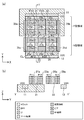
- (A) is a plan view showing a layout structure of a 2-input NAND cell
- (b) is a circuit diagram of a 2-input NAND.
- (A) and (b) are cross-sectional views of the two-input NAND cell of FIG. 2 (a).
- A) is a plan view showing the layout structure of the tri-state inverter cell
- (b) is a circuit diagram of the tri-state inverter.
- (A) and (b) are cross-sectional views of the tri-state inverter cell of FIG. 4 (a).
- (A) is a plan view showing the layout structure of the inverter cell, and (b) is a circuit diagram of the inverter.
- (A) is a plan view showing a layout structure of a 2-input NOR cell, and (b) is a circuit diagram of a 2-input NOR.
- It is a figure which shows the basic structure of a fork sheet FET (a) is a plan view, (b) is a sectional view.
- the semiconductor integrated circuit apparatus includes a plurality of standard cells (in the present specification, as appropriate, simply referred to as cells), and at least a part of the plurality of standard cells is a nanosheet FET (Field). Effect Transistor) shall be provided.
- the nanosheet FET is an FET using a thin sheet (nanosheet) through which an electric current flows. Nanosheets are made of, for example, silicon. Then, in the semiconductor integrated circuit device, a part of the nanosheet FET is a fork sheet FET having a fork-shaped gate electrode.
- the semiconductor layer portion formed at both ends of the nanosheet and forming the terminal serving as the source or drain of the nanosheet FET is referred to as a "pad".
- the horizontal direction of the drawing is the X direction (corresponding to the first direction)
- the vertical direction of the drawing is the Y direction (corresponding to the second direction)
- the direction perpendicular to the substrate surface is defined. It is in the Z direction (corresponding to the third direction).
- FIG. 10A and 10B are views showing the basic structure of the fork sheet FET, where FIG. 10A is a plan view and FIG. 10B is a cross-sectional view taken along the line YY'of FIG. 10A.
- FIG. 10A is a plan view
- FIG. 10B is a cross-sectional view taken along the line YY'of FIG. 10A.
- two transistors TR1 and TR2 are arranged side by side with an interval S in the Y direction.
- the gate wiring 531 that serves as the gate of the transistor TR1 and the gate wiring 532 that serves as the gate of the transistor TR2 both extend in the Y direction and are arranged at the same position in the X direction.
- the channel portion 521 which is the channel region of the transistor TR1 and the channel portion 526 which is the channel region of the transistor TR2 are composed of nanosheets.
- each of the channel portions 521 and 526 is composed of nanosheets having a three-sheet structure that overlaps in a plan view.
- Pads 522a and 522b serving as a source region or a drain region of the transistor TR1 are formed on both sides of the channel portion 521 in the X direction.
- Pads 527a and 527b serving as a source region or a drain region of the transistor TR2 are formed on both sides of the channel portion 526 in the X direction.
- the pads 522a and 522b are formed by epitaxial growth from the nanosheets constituting the channel portion 521.
- the pads 527a and 527b are formed by epitaxial growth from the nanosheets constituting the channel portion 526.
- the gate wiring 531 surrounds the outer periphery of the channel portion 521 made of nanosheets in the Y direction and the Z direction via a gate insulating film (not shown). However, in the nanosheet constituting the channel portion 521, the surface on the side of the transistor TR2 in the Y direction is not covered by the gate wiring 531 and is exposed from the gate wiring 531. That is, in the cross-sectional view of FIG. 10B, the gate wiring 531 does not cover the right side of the drawing of the nanosheet constituting the channel portion 521, but covers the upper side, the left side, and the lower side of the drawing. The gate wiring 531 overlaps the nanosheet constituting the channel portion 521 on the opposite side of the transistor TR2 in the Y direction by the length OL.
- the gate wiring 532 surrounds the outer periphery of the channel portion 526 made of nanosheets in the Y and Z directions via a gate insulating film (not shown). However, in the nanosheet constituting the channel portion 526, the surface on the side of the transistor TR1 in the Y direction is not covered by the gate wiring 532 and is exposed from the gate wiring 532. That is, in the cross-sectional view of FIG. 10B, the gate wiring 532 does not cover the left side of the drawing of the nanosheet constituting the channel portion 526, but covers the upper side, the right side, and the lower side of the drawing. The gate wiring 532 overlaps the nanosheet constituting the channel portion 526 on the opposite side of the transistor TR1 in the Y direction by the length OL.
- the effective gate width Weff 2 ⁇ W + H Will be. Since the channel portions 521 and 526 of the transistors TR1 and TR2 are composed of three nanosheets, the gate effective width of the transistors TR1 and TR2 is determined. 3x (2xW + H) Will be.
- the gate wiring 531 does not overlap the nanosheet constituting the channel portion 521 on the side of the transistor TR2 in the Y direction. Further, the gate wiring 532 does not overlap with the nanosheet constituting the channel portion 526 on the side of the transistor TR1 in the Y direction. As a result, the transistors TR1 and TR2 can be brought closer to each other, and the area can be reduced.
- the number of nanosheets constituting the channel portion of the transistor is not limited to three. That is, the nanosheet may have a single sheet structure, or may have a plurality of overlapping sheet structures in a plan view. Further, in FIG. 10B, the cross-sectional shape of the nanosheet is shown as a rectangle, but the cross-sectional shape of the nanosheet is not limited to this, and the cross-sectional shape of the nanosheet may be, for example, a square, a circle, an ellipse, or the like. ..
- the fork sheet FET and the nano sheet FET in which the gate wiring surrounds the entire circumference of the nano sheet may be mixed in the semiconductor integrated circuit device.
- VDD and VVSS indicate the power supply voltage or the power supply itself.
- expressions such as “same wiring width” that mean that the widths and the like are the same include a range of manufacturing variation.
- FIG. 1A and 1B are views showing an example of a basic structure of a standard cell having a fork sheet FET according to an embodiment, in which FIG. 1A is a plan view and FIG. 1B is a cross-sectional view taken along the line YY'of FIG. is there.
- FIG. 1A shows the cell frame CL of the standard cell. The same applies to the subsequent plan views.
- the standard cell of FIG. 1 is arranged side by side in the X direction in contact with the cell frame CL together with other standard cells to form a cell row. Further, the plurality of cell rows are arranged side by side in the Y direction in contact with the cell frame CL. However, the plurality of cell columns are flipped upside down every other column.
- power supply wirings 11 and 12 extending in the X direction are provided at both ends of the standard cell in the Y direction, respectively.
- Both the power supply wirings 11 and 12 are embedded power supply wirings (BPR: Buried Power Rail) formed in the embedded wiring layer.
- the power supply wiring 11 supplies the power supply voltage VDD
- the power supply wiring 12 supplies the power supply voltage VSS.
- the power supply wirings 11 and 12 are shared with other cells arranged side by side in the X direction to form a power supply wiring arranged between the cell rows.
- P-type transistors P11, P12, P21, and P22 are formed in the P-type region on the N well.
- N-type transistors N11, N12, N21, and N22 are formed in the N-type region on the P-type substrate.
- the transistors P11, P12, N11, and N12 are arranged in a row in the Y direction.
- the transistors P21, P22, N21, and N22 are arranged in a row in the Y direction.
- the transistors P11, P12, P21, and P22 each have nanosheets 21a, 23a, 21b, and 23b composed of three sheets as channel portions. That is, the transistors P11, P12, P21, and P22 are nanosheet FETs.
- a pad 22a composed of a semiconductor layer having an integral structure connected to three sheets, 22b and 22c are formed, respectively.
- the pads 22a and 22b serve as a source region and a drain region of the transistor P11.
- the pads 22b and 22c serve as a source region and a drain region of the transistor P21.
- Pads 24a, 24b, 24c made of a semiconductor layer having an integral structure connected to three sheets are formed on the left side of the drawing of the nanosheet 23a, between the nanosheets 23a and 23b, and on the right side of the drawing of the nanosheet 23b, respectively.
- the pads 24a and 24b serve as a source region and a drain region of the transistor P12.
- the pads 24b and 24c serve as a source region and a drain region of the transistor P22.
- the transistors N11, N12, N21, and N22 each have nanosheets 26a, 28a, 26b, and 28b composed of three sheets as channel portions. That is, the transistors N11, N12, N21, and N22 are nanosheet FETs.
- a pad 27a composed of a semiconductor layer having an integral structure connected to three sheets, 27b and 27c are formed, respectively.
- the pads 27a and 27b serve as a source region and a drain region of the transistor N11.
- the pads 27b and 27c serve as a source region and a drain region of the transistor N21.
- Pads 29a, 29b, 29c made of a semiconductor layer having an integral structure connected to three sheets are formed on the left side of the drawing of the nanosheet 28a, between the nanosheets 28a and 28b, and on the right side of the drawing of the nanosheet 28b, respectively.
- the pads 29a and 29b serve as a source region and a drain region of the transistor N12.
- the pads 29b and 29c serve as a source region and a drain region of the transistor N22.
- Gate wirings 31 and 32 extending in parallel in the Y direction are formed in the P-shaped region.
- Dummy gate wirings 35a and 35b are formed on the cell frame CLs on both sides of the gate wirings 31 and 32 in the X direction.
- the gate wirings 31 and 32 and the dummy gate wirings 35a and 35b are formed with the same width and are arranged at the same pitch.
- Gate wirings 33 and 34 extending in parallel in the Y direction are formed in the N-type region.
- Dummy gate wirings 35c and 35d are formed on the cell frame CLs on both sides of the gate wirings 33 and 34 in the X direction.
- the gate wirings 33 and 34 and the dummy gate wirings 35c and 35d are formed with the same width and are arranged at the same pitch.
- the gate wiring 31 surrounds the nanosheet 21a of the transistor P11 and the outer periphery of the nanosheet 23a of the transistor P12 in the Y and Z directions via a gate insulating film (not shown).
- the gate wiring 31 serves as a gate for the transistors P11 and P12.
- the gate wiring 32 surrounds the nanosheet 21b of the transistor P21 and the outer periphery of the nanosheet 23b of the transistor P22 in the Y direction and the Z direction via a gate insulating film (not shown).
- the gate wiring 32 serves as a gate for the transistors P21 and P22.
- the gate wiring 33 surrounds the nanosheet 26a of the transistor N11 and the outer periphery of the nanosheet 28a of the transistor N12 in the Y and Z directions via a gate insulating film (not shown).
- the gate wiring 33 serves as a gate for the transistors N11 and N12.
- the gate wiring 34 surrounds the nanosheet 26b of the transistor N21 and the outer periphery of the nanosheet 28b of the transistor N22 in the Y direction and the Z direction via a gate insulating film (not shown).
- the gate wiring 34 serves as a gate for the transistors N21 and N22.
- the surface on the side opposite to the N-shaped region in the Y direction (the surface on the side close to the power supply wiring 11) is not covered by the gate wirings 31 and 32, and from the gate wirings 31 and 32. It is exposed.
- the surface on the N-shaped region side in the Y direction is not covered by the gate wirings 31 and 32, but is exposed from the gate wirings 31 and 32.
- the nanosheets 21a and 23a constitute the first nanosheet group
- the nanosheet 21a corresponds to the first nanosheet farthest from the N-type region in the first nanosheet group
- the nanosheet 23a corresponds to the first nanosheet group. It corresponds to the second nanosheet closest to the N-type region.
- the surface on the P-shaped region side in the Y direction is not covered by the gate wirings 33 and 34, and is exposed from the gate wirings 33 and 34.
- the surface opposite to the P-shaped region in the Y direction (the surface closer to the power supply wiring 12) is not covered by the gate wirings 33 and 34, and is exposed from the gate wirings 33 and 34.
- the nanosheets 26a and 28a constitute the second nanosheet group
- the nanosheet 28a corresponds to the third nanosheet farthest from the P-type region in the second nanosheet group
- the nanosheet 26a is in the second nanosheet group. It corresponds to the 4th nanosheet closest to the P-type region.
- the power supply wirings 11 and 12 are embedded power supply wirings, the present invention is not limited to this, and for example, the power supply wirings may be formed in the upper metal wiring layer.
- transistors are arranged in the X direction, but the present invention is not limited to this.
- only one transistor may be arranged in the X direction, or three or more transistors may be arranged in the X direction. You may be.
- FIG. 2 (a) is a plan view showing the layout structure of the 2-input NAND cell
- FIG. 2 (b) is a circuit diagram of the 2-input NAND
- FIG. 3 (a) is a cross section of line Y1-Y1'of FIG. 2 (a).
- FIG. 3 (b) is a cross-sectional view taken along the line Y2-Y2'of FIG. 2 (a).
- local wirings 41, 42, 43, 44, 45 extending in the Y direction are formed.
- the local wiring 41 is connected to the pads 22a and 24a.
- the local wiring 42 is connected to the pads 22b and 24b, and is also connected to the power supply wiring 11 via vias.
- the local wiring 43 is connected to the pads 22c, 24c, 27c, 29c.
- the local wiring 44 is connected to the pads 27a and 29a, and is also connected to the power supply wiring 12 via vias.
- the local wiring 45 is connected to the pads 27b and 29b.
- the gate wirings 31 and 33 arranged in the Y direction are connected via a bridge portion 36a formed between the gate wiring 31 and the gate wiring 33.
- the gate wirings 32 and 34 arranged in the Y direction are connected via a bridge portion 36b formed between the gate wiring 32 and the gate wiring 34.
- the bridge portions 36a and 36b are examples of gate connection portions.
- metal wirings 51, 52, 53 extending in the X direction are formed.
- the metal wiring 51 is connected to the local wirings 41 and 43 via vias.
- the metal wiring 52 is connected to the gate wirings 32 and 34 via vias.
- the metal wiring 53 is connected to the gate wirings 31 and 33 via vias.
- the metal wirings 51, 52, and 53 correspond to the outputs Y and the inputs A and B of the 2-input NAND, respectively.
- FIG. 4 (a) is a plan view showing the layout structure of the tri-state inverter cell
- FIG. 4 (b) is a circuit diagram of the tri-state inverter
- FIG. 5 (a) is a cross section of line Y1-Y1'of FIG. 4 (a).
- FIG. 4 (b) is a cross-sectional view taken along the line Y2-Y2'of FIG. 4 (a).
- local wirings 61, 62, 63, 64, 65 extending in the Y direction are formed.
- the local wiring 61 is connected to the pads 22a and 24a, and is connected to the power supply wiring 11 via vias.
- the local wiring 62 is connected to the pads 22b and 24b.
- the local wiring 63 is connected to the pads 22c, 24c, 27c, 29c.
- the local wiring 64 is connected to the pads 27a and 29a, and is also connected to the power supply wiring 12 via vias.
- the local wiring 65 is connected to the pads 27b and 29b.
- the gate wirings 31 and 33 arranged in the Y direction are connected via a bridge portion 37 formed between the gate wiring 31 and the gate wiring 33.
- the gate wires 32, 34 lined up in the Y direction are not connected and remain separated.
- metal wirings 71, 72, 73, 74 extending in the X direction are formed.
- the metal wiring 71 is connected to the gate wiring 32 via vias.
- the metal wiring 72 is connected to the gate wirings 31 and 33 via vias.
- the metal wiring 73 is connected to the gate wiring 34 via vias.
- the metal wiring 74 is connected to the local wiring 63 via a via.
- the metal wirings 71, 72, 73, and 74 correspond to the inputs NE, A, E, and the output Y of the tri-state inverter, respectively.
- FIG. 6A is a plan view showing the layout structure of the inverter cell
- FIG. 6B is a circuit diagram of the inverter.
- This inverter cell is based on a basic structure in which only one transistor is arranged in the X direction. In this basic structure, it is assumed that only the transistors P11, P12, N11, and N12 of FIG. 1 are formed.
- local wirings 81, 82, 83 extending in the Y direction are formed.
- the local wiring 81 is connected to the pads 22a and 24a, and is also connected to the power supply wiring 11 via vias.
- the local wiring 82 is connected to the pads 22b, 24b, 27b, 29b.
- the local wiring 83 is connected to the pads 27a and 29a, and is also connected to the power supply wiring 12 via vias.
- the gate wirings 31 and 33 arranged in the Y direction are connected via a bridge portion 38 formed between the gate wiring 31 and the gate wiring 33.
- metal wirings 91 and 92 extending in the X direction are formed.
- the metal wiring 91 is connected to the gate wirings 31 and 33 via vias.
- the metal wiring 92 is connected to the local wiring 82 via a via.
- the metal wirings 91 and 92 correspond to the input A and the output Y of the inverter, respectively.
- FIG. 7A is a plan view showing the layout structure of the 2-input NOR cell
- FIG. 7B is a circuit diagram of the 2-input NOR.
- local wirings 101, 102, 103, 104, 105 extending in the Y direction are formed.
- the local wiring 101 is connected to the pads 22a and 24a, and is also connected to the power supply wiring 11 via vias.
- the local wiring 102 is connected to the pads 22b and 24b.
- the local wiring 103 is connected to the pads 22c, 24c, 27c, 29c.
- the local wiring 104 is connected to the pads 27a and 29a.
- the local wiring 105 is connected to the pads 27b and 29b, and is also connected to the power supply wiring 12 via via vias.
- the gate wirings 31 and 33 arranged in the Y direction are connected via a bridge portion 39a formed between the gate wiring 31 and the gate wiring 33.
- the gate wirings 32 and 34 arranged in the Y direction are connected via a bridge portion 39b formed between the gate wiring 32 and the gate wiring 34.
- metal wirings 111, 112, 113 extending in the X direction are formed.
- the metal wiring 111 is connected to the gate wirings 31 and 33 via vias.
- the metal wiring 112 is connected to the gate wirings 32 and 34 via vias.
- the metal wiring 113 is connected to the local wirings 103 and 104 via vias.
- the metal wirings 111, 112, and 113 correspond to inputs B, A, and output Y of the two-input NOR, respectively.
- the surfaces of the nanosheets 21a and 21b on the side far from the N-type region in the Y direction are exposed from the gate wirings 31 and 32.
- the gate wirings 31 and 32 do not overlap from the nanosheets 21a and 21b to the power supply wiring 11 side.
- the surface on the side far from the P-shaped region in the Y direction is exposed from the gate wirings 33 and 34.
- the gate wirings 33 and 34 do not overlap from the nanosheets 28a and 28b to the power supply wiring 12 side. Therefore, at the boundary between adjacent cells in the Y direction, the space required between the nanosheets of one cell and the nanosheets of the other cell becomes smaller.
- the surface on the N-shaped region side in the Y direction is exposed from the gate wirings 31 and 32.
- the gate wirings 31 and 32 do not overlap from the nanosheets 23a and 23b to the N-type region side.
- the surface on the P-shaped region side in the Y direction is exposed from the gate wirings 33 and 34.
- the gate wirings 33 and 34 do not overlap from the nanosheets 26a and 26b to the P-type region side. Therefore, at the boundary between the P-type region and the N-type region, the space required between the nanosheet in the P-type region and the nanosheet in the N-type region becomes smaller.
- the size of the semiconductor integrated circuit device having the fork sheet FET in the Y direction can be effectively reduced.
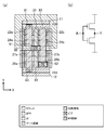
- FIG. 8 is a diagram showing a basic structure of a standard cell having a fork sheet FET according to a modified example, (a) is a plan view, and (b) is a cross-sectional view taken along the line YY'of (a).
- the transistors are arranged in three rows in the Y direction in the P-type region on the N-well, and the transistors are arranged in three rows in the Y direction in the N-type region on the P-type substrate. That is, P-type transistors P11, P12, P13, P21, P22, and P23 are formed in the P-type region. N-type transistors N11, N12, N13, N21, N22, and N23 are formed in the N-type region. The transistors P11, P12, P13, N11, N12, and N13 are arranged in a row in the Y direction. The transistors P21, P22, P23, N21, N22, and N23 are arranged in a row in the Y direction.
- the transistors P11, P12, P13, P21, P22, and P23 have nanosheets 121a, 122a, 123a, 121b, 122b, and 123b, which are composed of three sheets, as channel portions, respectively.
- the transistors N11, N12, N13, N21, N22, and N23 have nanosheets 124a, 125a, 126a, 124b, 125b, and 126b, which are composed of three sheets, as channel portions, respectively.
- Gate wirings 131 and 132 extending in parallel in the Y direction are formed in the P-shaped region.
- the gate wiring 131 surrounds the nanosheet 121a of the transistor P11, the nanosheet 122a of the transistor P12, and the outer periphery of the nanosheet 123a of the transistor P13 in the Y and Z directions via a gate insulating film (not shown).
- the gate wiring 131 serves as a gate for the transistors P11, P12, and P13.
- the gate wiring 132 surrounds the nanosheet 121b of the transistor P21, the nanosheet 122b of the transistor P22, and the outer periphery of the nanosheet 123b of the transistor P23 in the Y and Z directions via a gate insulating film (not shown).
- the gate wiring 132 serves as a gate for the transistors P21, P22, and P23.
- Gate wiring 133, 134 extending in parallel in the Y direction is formed in the N-type region.
- the gate wiring 133 surrounds the nanosheet 124a of the transistor N11, the nanosheet 125a of the transistor N12, and the outer periphery of the nanosheet 126a of the transistor N13 in the Y and Z directions via a gate insulating film (not shown).
- the gate wiring 133 serves as a gate for the transistors N11, N12, and N13.
- the gate wiring 134 surrounds the nanosheet 124b of the transistor N21, the nanosheet 125b of the transistor N22, and the outer periphery of the nanosheet 126b of the transistor N23 in the Y and Z directions via a gate insulating film (not shown).
- the gate wiring 134 serves as a gate for the transistors N21, N22, and N23.
- the surface opposite to the N-shaped region in the Y direction is not covered by the gate wirings 131 and 132, and the nanosheets 121a and 121b are formed from the gate wirings 131 and 132. It is exposed.
- the surface on the N-shaped region side in the Y direction is not covered by the gate wirings 131 and 132, but is exposed from the gate wirings 131 and 132.
- the nanosheets 121a, 122a, 123a constitute the first nanosheet group
- the nanosheet 121a corresponds to the first nanosheet farthest from the N-type region in the first nanosheet group
- the nanosheet 123a is the first nanosheet. It corresponds to the second nanosheet closest to the N-type region in the group.
- the surface on the P-shaped region side in the Y direction is not covered by the gate wirings 133 and 134, but is exposed from the gate wirings 133 and 134.
- the surface opposite to the P-shaped region in the Y direction (the surface closer to the power supply wiring 12) is not covered by the gate wiring 133 and 134, and is exposed from the gate wiring 133 and 134.
- the nanosheets 124a, 125a, 126a constitute the second nanosheet group
- the nanosheet 126a corresponds to the third nanosheet farthest from the P-type region in the second nanosheet group
- the nanosheet 124a is the second nanosheet group.
- the nanosheets 122a and 122b are surrounded by gate wirings 131 and 132 all around in the Y direction.
- the entire circumference of the nanosheets 125a and 125b in the Y direction is surrounded by gate wiring 133 and 134.
- the same action and effect as those in the above-described embodiment can be obtained. That is, at the boundary between adjacent cells in the Y direction, the space required between the nanosheets of one cell and the nanosheets of the other cell becomes smaller. Further, at the boundary portion between the P-type region and the N-type region, the space required between the nanosheet in the P-type region and the nanosheet in the N-type region becomes smaller. Therefore, the size of the semiconductor integrated circuit device having the fork sheet FET in the Y direction can be effectively reduced.
- Modification 2 9A and 9B are views showing the basic structure of a standard cell having a fork sheet FET according to a modified example, FIG. 9A is a plan view, and FIG. 9B is a sectional view taken along line YY'of FIG. 9A.
- the transistors are arranged in four rows in the Y direction in the P-type region on the N-well, and the transistors are arranged in four rows in the Y direction in the N-type region on the P-type substrate. That is, P-type transistors P11, P12, P13, P14, P21, P22, P23, and P24 are formed in the P-type region. N-type transistors N11, N12, N13, N14, N21, N22, N23, and N24 are formed in the N-type region. The transistors P11, P12, P13, P14, N11, N12, N13, and N14 are arranged in a row in the Y direction. The transistors P21, P22, P23, P24, N21, N22, N23, and N24 are arranged in a row in the Y direction.
- Transistors P11, P12, P13, P14, P21, P22, P23, P24 have nanosheets 221a, 222a, 223a, 224a, 221b, 222b, 223b, 224b, respectively, as channel portions.
- the transistors N11, N12, N13, N14, N21, N22, N23, and N24 have nanosheets 225a, 226a, 227a, 228a, 225b, 226b, 227b, and 228b, respectively, as channel portions.
- Gate wirings 231 and 232 extending in parallel in the Y direction are formed in the P-shaped region.
- the gate wiring 231 surrounds the nanosheet 221a of the transistor P11 and the outer periphery of the nanosheet 222a of the transistor P12 in the Y and Z directions via a gate insulating film (not shown).
- the gate wiring 231 serves as a gate for the transistors P11 and P12.
- the gate wiring 232 surrounds the nanosheet 221b of the transistor P21 and the outer periphery of the nanosheet 222b of the transistor P22 in the Y direction and the Z direction via a gate insulating film (not shown).
- the gate wiring 232 serves as a gate for the transistors P21 and P22.
- gate wirings 233 and 234 extending in parallel in the Y direction are formed.
- the gate wiring 233 is in the same position as the gate wiring 231 in the X direction, and the gate wiring 234 is in the same position as the gate wiring 232 in the X direction.
- the gate wiring 233 surrounds the nanosheet 223a of the transistor P13 and the outer periphery of the nanosheet 224a of the transistor P14 in the Y and Z directions via a gate insulating film (not shown).
- the gate wiring 233 serves as a gate for the transistors P13 and P14.
- the gate wiring 234 surrounds the nanosheet 223b of the transistor P23 and the outer periphery of the nanosheet 224b of the transistor P24 in the Y direction and the Z direction via a gate insulating film (not shown).
- the gate wiring 234 serves as a gate for the transistors P23 and P24.
- Gate wirings 235 and 236 extending in parallel in the Y direction are formed in the N-shaped region.
- the gate wiring 235 surrounds the nanosheet 225a of the transistor N11 and the outer periphery of the nanosheet 226a of the transistor N12 in the Y and Z directions via a gate insulating film (not shown).
- the gate wiring 235 serves as a gate for the transistors N11 and N12.
- the gate wiring 236 surrounds the nanosheet 225b of the transistor N21 and the outer periphery of the nanosheet 226b of the transistor N22 in the Y direction and the Z direction via a gate insulating film (not shown).
- the gate wiring 236 serves as a gate for the transistors N21 and N22.
- gate wirings 237 and 238 extending in parallel in the Y direction are formed.
- the gate wiring 237 is in the same position as the gate wiring 235 in the X direction, and the gate wiring 238 is in the same position as the gate wiring 236 in the X direction.
- the gate wiring 237 surrounds the nanosheet 227a of the transistor N13 and the outer periphery of the nanosheet 228a of the transistor N14 in the Y and Z directions via a gate insulating film (not shown).
- the gate wiring 237 serves as a gate for the transistors N13 and N14.
- the gate wiring 238 surrounds the nanosheet 227b of the transistor N23 and the outer periphery of the nanosheet 228b of the transistor N24 in the Y direction and the Z direction via a gate insulating film (not shown).
- the gate wiring 238 serves as a gate for the transistors N23 and N24.
- the surface on the side opposite to the N-shaped region in the Y direction (the surface on the side close to the power supply wiring 11) is not covered by the gate wirings 231,232, and the gate wirings 231 and 232 It is exposed.
- the surface on the N-shaped region side in the Y direction is not covered by the gate wirings 233 and 234, but is exposed from the gate wirings 233 and 234.
- the nanosheets 221a, 222a, 223a, 224a constitute the first nanosheet group
- the nanosheet 221a corresponds to the first nanosheet farthest from the N-type region in the first nanosheet group
- the nanosheet 224a is the first nanosheet group. It corresponds to the second nanosheet closest to the N-type region in one nanosheet group.
- the gate wirings 231 and 233 correspond to the first gate wiring.
- the first gate wiring is separated between the nanosheet 222a and the nanosheet 223a.
- nanosheets 225a and 225b the surface on the P-shaped region side in the Y direction is not covered by the gate wirings 235 and 236, and is exposed from the gate wirings 235 and 236.
- the surface opposite to the P-shaped region in the Y direction (the surface closer to the power supply wiring 12) is not covered by the gate wirings 237 and 238, and is exposed from the gate wirings 237 and 238.
- nanosheets 225a, 226a, 227a, 228a constitute the second nanosheet group
- nanosheet 228a corresponds to the third nanosheet farthest from the P-type region in the second nanosheet group
- nanosheet 225a is the second nanosheet group.
- the gate wirings 235 and 237 correspond to the second gate wiring.
- the second gate wiring is separated between the nanosheet 226a and the nanosheet 227a.
- the same action and effect as those in the above-described embodiment can be obtained. That is, at the boundary between adjacent cells in the Y direction, the space required between the nanosheets of one cell and the nanosheets of the other cell becomes smaller. Further, at the boundary portion between the P-type region and the N-type region, the space required between the nanosheet in the P-type region and the nanosheet in the N-type region becomes smaller. Therefore, the size of the semiconductor integrated circuit device having the fork sheet FET in the Y direction can be effectively reduced.
- the surfaces of the nanosheets 222a and 222b facing the nanosheets 223a and 223b are not covered by the gate wirings 231,232 and are exposed from the gate wirings 231,232.
- the surfaces of the nanosheets 223a and 223b facing the nanosheets 222a and 222b are not covered by the gate wirings 233 and 234 and are exposed from the gate wirings 233 and 234.
- the nanosheets 222a and 223a are located between the first nanosheet and the second nanosheet in the first nanosheet group, and correspond to the fifth and sixth nanosheets adjacent to each other in the Y direction.
- the surfaces of the nanosheets 226a and 226b facing the nanosheets 227a and 227b are not covered by the gate wirings 235 and 236 and are exposed from the gate wirings 235 and 236.
- the surfaces of the nanosheets 227a and 227b facing the nanosheets 226a and 226b are not covered by the gate wirings 237 and 238 and are exposed from the gate wirings 237 and 238.
- the nanosheets 226a and 227a are located between the third nanosheet and the fourth nanosheet in the second nanosheet group, and correspond to the seventh and eighth nanosheets adjacent to each other in the Y direction.
- the gate wiring 231 and the gate wiring 233 are separated, different signals can be given to the gates of the transistors P11 and P12 and the gates of the transistors P13 and P14. Since the gate wiring 232 and the gate wiring 234 are separated, different signals can be given to the gates of the transistors P21 and P22 and the gates of the transistors P23 and P24. Further, since the gate wiring 235 and the gate wiring 237 are separated, different signals can be given to the gates of the transistors N11 and N12 and the gates of the transistors N13 and N14. Since the gate wiring 236 and the gate wiring 238 are separated, different signals can be given to the gates of the transistors N21 and N22 and the gates of the transistors N23 and N24. Therefore, the degree of freedom of the logic circuit that can be configured is improved.
- the space required between the transistors P12 and P22 and the transistors P13 and P23, that is, between the nanosheets 222a and 222b and the nanosheets 223a and 223b can be small.
- the space required between the transistors N12 and N22 and the transistors N13 and N23, that is, between the nanosheets 226a and 226b and the nanosheets 227a and 227b can be small. Therefore, the size of the semiconductor integrated circuit device having the fork sheet FET in the Y direction can be further effectively reduced.
- the gate wiring 231,233, the gate wiring 232, 234, the gate wiring 235, 237, and the gate wiring 236, 238 may be integrally formed without being separated from each other.
- a layout structure having a small area can be realized for a semiconductor integrated circuit device using a fork sheet FET, which is useful for, for example, miniaturization of a semiconductor chip and improvement of the degree of integration.
Landscapes
- Engineering & Computer Science (AREA)
- Power Engineering (AREA)
- Microelectronics & Electronic Packaging (AREA)
- Condensed Matter Physics & Semiconductors (AREA)
- Computer Hardware Design (AREA)
- Physics & Mathematics (AREA)
- General Physics & Mathematics (AREA)
- Ceramic Engineering (AREA)
- Chemical & Material Sciences (AREA)
- Nanotechnology (AREA)
- Crystallography & Structural Chemistry (AREA)
- Materials Engineering (AREA)
- Manufacturing & Machinery (AREA)
- General Engineering & Computer Science (AREA)
- Design And Manufacture Of Integrated Circuits (AREA)
Abstract
According to the present invention, a nano sheet (21a) which is positioned in a P-type region to be furthest from an N-type region has a surface that is exposed from a gate wiring line (31), said surface being on the reverse side from the N-type region in the Y direction; a nano sheet (28a) which is positioned in the N-type region to be furthest from the P-type region has a surface that is exposed from a gate wiring line (33), said surface being on the reverse side from the P-type region in the Y direction; a nano sheet (23a) which is positioned in the P-type region to be closest to the N-type region has a surface that is exposed from the gate wiring line (31), said surface being on the N-type region side in the Y direction; and a nano sheet (26a) which is positioned in the N-type region to be closest to the P-type region has a surface that is exposed from the gate wiring line (33), said surface being on the P-type region side in the Y direction.
Description
本開示は、ナノシート(ナノワイヤ)FET(Field Effect Transistor)を備えた半導体集積回路装置に関する。
The present disclosure relates to a semiconductor integrated circuit device provided with a nanosheet (nanowire) FET (Field Effect Transistor).
半導体基板上に半導体集積回路を形成する方法として、スタンダードセル方式が知られている。スタンダードセル方式とは、特定の論理機能を有する基本的単位(例えば、インバータ,ラッチ,フリップフロップ,全加算器など)をスタンダードセルとして予め用意しておき、半導体基板上に複数のスタンダードセルを配置して、それらのスタンダードセルを配線で接続することによって、LSIチップを設計する方式のことである。
The standard cell method is known as a method for forming a semiconductor integrated circuit on a semiconductor substrate. In the standard cell method, a basic unit having a specific logical function (for example, an inverter, a latch, a flip-flop, a full adder, etc.) is prepared in advance as a standard cell, and a plurality of standard cells are arranged on a semiconductor substrate. Then, it is a method of designing an LSI chip by connecting these standard cells with wiring.
また、LSIの基本構成要素であるトランジスタは、ゲート長の縮小(スケーリング)により、集積度の向上、動作電圧の低減、および動作速度の向上を実現してきた。しかし近年、過度なスケーリングによるオフ電流と、それによる消費電力の著しい増大が問題となっている。この問題を解決するため、トランジスタ構造を従来の平面型から立体型に変更した立体構造トランジスタが盛んに研究されている。その1つとして、ナノシート(ナノワイヤ)FETが注目されている。
In addition, the transistor, which is a basic component of the LSI, has realized an improvement in the degree of integration, a reduction in the operating voltage, and an improvement in the operating speed by reducing (scaling) the gate length. However, in recent years, off-current due to excessive scaling and a significant increase in power consumption due to the off-current have become problems. In order to solve this problem, three-dimensional structure transistors in which the transistor structure is changed from the conventional two-dimensional type to the three-dimensional type are being actively studied. As one of them, nanosheet (nanowire) FETs are attracting attention.
非特許文献1では、ゲート電極をフォーク形状としたナノシートFETを用いたSRAMメモリセルのレイアウトが開示されている。
Non-Patent Document 1 discloses a layout of a SRAM memory cell using a nanosheet FET having a fork-shaped gate electrode.
本明細書では、ゲート電極をフォーク形状としたナノシートFETのことを、非特許文献1の記載にならい、フォークシート(fork sheet)FETと呼ぶことにする。
In this specification, a nanosheet FET having a fork-shaped gate electrode is referred to as a forksheet FET, following the description in Non-Patent Document 1.
これまで、フォークシートFETを用いたスタンダードセルのレイアウト構造や、フォークシートFETを用いた半導体集積回路のレイアウトについて、開示した文献はない。
So far, there is no document that discloses the layout structure of a standard cell using a fork sheet FET and the layout of a semiconductor integrated circuit using a fork sheet FET.
本開示は、小面積の、フォークシートFETを用いた半導体集積回路装置のレイアウト構造を提供することを目的とする。
An object of the present disclosure is to provide a layout structure of a semiconductor integrated circuit device using a fork sheet FET with a small area.
本開示の第1態様では、第1方向に並べて配置されたスタンダードセルを備える半導体集積回路装置において、前記スタンダードセルは、P型トランジスタが形成されるP型領域とN型トランジスタが形成されるN型領域とが、前記第1方向と垂直をなす第2方向において隣接して形成されており、前記P型領域において、前記第1方向にそれぞれ延びており、前記第2方向に並ぶ2つ以上のナノシートからなる、第1ナノシート群と、前記N型領域において、前記第1方向にそれぞれ延びており、前記第2方向に並ぶ2つ以上のナノシートからなる、第2ナノシート群と、前記第2方向に延びており、前記第1ナノシート群の各ナノシートの前記第2方向、並びに、前記第1および第2方向と垂直をなす第3方向における外周を囲うように形成された第1ゲート配線と、前記第2方向に延びており、前記第2ナノシート群の各ナノシートの前記第2方向および前記第3方向における外周を囲うように形成された第2ゲート配線とを備え、前記第1ナノシート群において、前記N型領域から最も遠い第1ナノシートは、前記第2方向における前記N型領域と反対側の面が、前記第1ゲート配線から露出しており、前記N型領域に最も近い第2ナノシートは、前記第2方向における前記N型領域側の面が、前記第1ゲート配線から露出しており、前記第2ナノシート群において、前記P型領域から最も遠い第3ナノシートは、前記第2方向における前記P型領域と反対側の面が、前記第2ゲート配線から露出しており、前記P型領域に最も近い第4ナノシートは、前記第2方向における前記P型領域側の面が、前記第2ゲート配線から露出している。
In the first aspect of the present disclosure, in a semiconductor integrated circuit apparatus including standard cells arranged side by side in the first direction, the standard cell has a P-type region in which a P-type transistor is formed and an N in which an N-type transistor is formed. Two or more mold regions are formed adjacent to each other in a second direction perpendicular to the first direction, extend in each of the first directions in the P-shaped region, and are lined up in the second direction. The first nanosheet group consisting of the above nanosheets, the second nanosheet group consisting of two or more nanosheets extending in the first direction and lining up in the second direction in the N-type region, and the second nanosheet group. With the first gate wiring extending in the direction and surrounding the outer periphery in the second direction of each nanosheet of the first nanosheet group and the third direction perpendicular to the first and second directions. The first nanosheet group includes a second gate wiring that extends in the second direction and is formed so as to surround the outer periphery of each nanosheet in the second nanosheet group in the second direction and the third direction. In the first nanosheet farthest from the N-type region, the surface opposite to the N-type region in the second direction is exposed from the first gate wiring, and the second nanosheet closest to the N-type region. In the nanosheet, the surface on the N-type region side in the second direction is exposed from the first gate wiring, and in the second nanosheet group, the third nanosheet farthest from the P-type region is the second nanosheet. The surface opposite to the P-type region in the direction is exposed from the second gate wiring, and the fourth nanosheet closest to the P-type region has a surface on the P-type region side in the second direction. It is exposed from the second gate wiring.
この態様によると、P型領域における第1ナノシート群において、N型領域から最も遠い第1ナノシートは、第2方向におけるN型領域と反対側の面が第1ゲート配線から露出している。N型領域における第2ナノシート群において、P型領域から最も遠い第3ナノシートは、第2方向におけるP型領域と反対側の面が第2ゲート配線から露出している。すなわち、第1ゲート配線は、第1ナノシート群に対してスタンダードセル外側に向けてオーバーラップしておらず、第2ゲート配線は、第2ナノシート群に対してスタンダードセル外側に向けてオーバーラップしていない。また、P型領域における第1ナノシート群において、N型領域に最も近い第2ナノシートは、第2方向におけるN型領域側の面が第1ゲート配線から露出している。N型領域における第2ナノシート群において、P型領域に最も近い第4ナノシートは、第2方向におけるP型領域側の面が第2ゲート配線から露出している。すなわち、第1ゲート配線は、第1ナノシート群に対して第2ナノシート群に向けてオーバーラップしておらず、第2ゲート配線は、第2ナノシート群に対して第1ナノシート群に向けてオーバーラップしていない。このため、スタンダードセルの第2方向のサイズを縮小することができるので、小面積のレイアウト構造を実現することができる。
According to this aspect, in the first nanosheet group in the P-type region, the surface of the first nanosheet farthest from the N-type region on the side opposite to the N-type region in the second direction is exposed from the first gate wiring. In the second nanosheet group in the N-type region, the surface of the third nanosheet farthest from the P-type region on the side opposite to the P-type region in the second direction is exposed from the second gate wiring. That is, the first gate wiring does not overlap the first nanosheet group toward the outside of the standard cell, and the second gate wiring overlaps the second nanosheet group toward the outside of the standard cell. Not. Further, in the first nanosheet group in the P-type region, the surface of the second nanosheet closest to the N-type region on the N-type region side in the second direction is exposed from the first gate wiring. In the second nanosheet group in the N-type region, the surface of the fourth nanosheet closest to the P-type region on the P-type region side in the second direction is exposed from the second gate wiring. That is, the first gate wiring does not overlap the first nanosheet group toward the second nanosheet group, and the second gate wiring overlaps the second nanosheet group toward the first nanosheet group. Not wrapped. Therefore, the size of the standard cell in the second direction can be reduced, so that a layout structure having a small area can be realized.
本開示の第2態様では、半導体集積回路装置は、第1方向に延びており、第1電源電圧を供給する第1電源配線と、前記第1方向に延びており、第2電源電圧を供給する第2電源配線とを備え、前記第1電源配線と前記第2電源配線との間に、P型トランジスタが形成されるP型領域とN型トランジスタが形成されるN型領域とが、前記第1方向と垂直をなす第2方向において隣接して形成されており、さらに、前記P型領域において、前記第1方向に延びており、前記第2方向に並ぶ2つ以上のナノシートからなる、第1ナノシート群と、前記N型領域において、前記第1方向に延びており、前記第2方向に並ぶ2つ以上のナノシートからなる、第2ナノシート群と、前記第2方向に延びており、前記第1ナノシート群の各ナノシートの前記第2方向、並びに、前記第1および第2方向と垂直をなす第3方向における外周を囲うように形成された第1ゲート配線と、前記第2方向に延びており、前記第2ナノシート群の各ナノシートの前記第2方向および前記第3方向における外周を囲うように形成された第2ゲート配線とを備え、前記第1ナノシート群において、前記N型領域から最も遠い第1ナノシートは、前記第2方向における前記N型領域と反対側の面が、前記第1ゲート配線から露出しており、前記N型領域に最も近い第2ナノシートは、前記第2方向における前記N型領域側の面が、前記第1ゲート配線から露出しており、前記第2ナノシート群において、前記P型領域から最も遠い第3ナノシートは、前記第2方向における前記P型領域と反対側の面が、前記第2ゲート配線から露出しており、前記P型領域に最も近い第4ナノシートは、前記第2方向における前記P型領域側の面が、前記第2ゲート配線から露出している。
In the second aspect of the present disclosure, the semiconductor integrated circuit device extends in the first direction and supplies the first power supply wiring, and extends in the first direction and supplies the second power supply voltage. A P-type region in which a P-type transistor is formed and an N-type region in which an N-type transistor is formed are formed between the first power supply wiring and the second power supply wiring. It is formed adjacent to each other in a second direction perpendicular to the first direction, and further extends in the first direction in the P-shaped region, and is composed of two or more nanosheets arranged in the second direction. The first nanosheet group and the second nanosheet group consisting of two or more nanosheets extending in the first direction and lining up in the second direction in the N-type region and extending in the second direction. The first gate wiring formed so as to surround the outer periphery in the second direction of each nanosheet of the first nanosheet group and the third direction perpendicular to the first and second directions, and the second direction. In the first nanosheet group, the N-shaped region includes a second gate wiring that extends and is formed so as to surround the outer periphery of each nanosheet of the second nanosheet group in the second direction and the third direction. The surface of the first nanosheet farthest from the N-type region is exposed from the first gate wiring in the second direction, and the second nanosheet closest to the N-type region is the second nanosheet. The surface on the N-type region side in the direction is exposed from the first gate wiring, and in the second nanosheet group, the third nanosheet farthest from the P-type region is the P-type region in the second direction. The surface opposite to the second gate wiring is exposed from the second gate wiring, and in the fourth nanosheet closest to the P-type region, the surface on the P-type region side in the second direction is from the second gate wiring. It is exposed.
この態様によると、P型領域における第1ナノシート群において、N型領域から最も遠い第1ナノシートは、第2方向におけるN型領域と反対側の面が第1ゲート配線から露出している。N型領域における第2ナノシート群において、P型領域から最も遠い第3ナノシートは、第2方向におけるP型領域と反対側の面が第2ゲート配線から露出している。すなわち、第1ゲート配線は、第1ナノシート群に対して電源配線側に向けてオーバーラップしておらず、第2ゲート配線は、第2ナノシート群に対して電源配線側に向けてオーバーラップしていない。また、P型領域における第1ナノシート群において、N型領域に最も近い第2ナノシートは、第2方向におけるN型領域側の面が第1ゲート配線から露出している。N型領域における第2ナノシート群において、P型領域に最も近い第4ナノシートは、第2方向におけるP型領域側の面が第2ゲート配線から露出している。すなわち、第1ゲート配線は、第1ナノシート群に対して第2ナノシート群に向けてオーバーラップしておらず、第2ゲート配線は、第2ナノシート群に対して第1ナノシート群に向けてオーバーラップしていない。このため、半導体集積回路装置の第2方向のサイズを縮小することができるので、小面積のレイアウト構造を実現することができる。
According to this aspect, in the first nanosheet group in the P-type region, the surface of the first nanosheet farthest from the N-type region on the side opposite to the N-type region in the second direction is exposed from the first gate wiring. In the second nanosheet group in the N-type region, the surface of the third nanosheet farthest from the P-type region on the side opposite to the P-type region in the second direction is exposed from the second gate wiring. That is, the first gate wiring does not overlap the first nanosheet group toward the power supply wiring side, and the second gate wiring overlaps the second nanosheet group toward the power supply wiring side. Not. Further, in the first nanosheet group in the P-type region, the surface of the second nanosheet closest to the N-type region on the N-type region side in the second direction is exposed from the first gate wiring. In the second nanosheet group in the N-type region, the surface of the fourth nanosheet closest to the P-type region on the P-type region side in the second direction is exposed from the second gate wiring. That is, the first gate wiring does not overlap the first nanosheet group toward the second nanosheet group, and the second gate wiring overlaps the second nanosheet group toward the first nanosheet group. Not wrapped. Therefore, the size of the semiconductor integrated circuit device in the second direction can be reduced, so that a layout structure having a small area can be realized.
本開示によると、フォークシートFETを用いた半導体集積回路装置について、小面積のレイアウト構造が実現できる。
According to the present disclosure, a layout structure having a small area can be realized for a semiconductor integrated circuit device using a fork sheet FET.
以下、実施の形態について、図面を参照して説明する。以下の実施の形態では、半導体集積回路装置は、複数のスタンダードセル(本明細書では、適宜、単にセルという)を備えており、この複数のスタンダードセルのうち少なくとも一部は、ナノシートFET(Field Effect Transistor)を備えるものとする。ナノシートFETとは、電流が流れる薄いシート(ナノシート)を用いたFETである。ナノシートは例えばシリコンによって形成されている。そして、半導体集積回路装置において、ナノシートFETの一部は、ゲート電極をフォーク形状としたフォークシートFETであるものとする。
Hereinafter, embodiments will be described with reference to the drawings. In the following embodiments, the semiconductor integrated circuit apparatus includes a plurality of standard cells (in the present specification, as appropriate, simply referred to as cells), and at least a part of the plurality of standard cells is a nanosheet FET (Field). Effect Transistor) shall be provided. The nanosheet FET is an FET using a thin sheet (nanosheet) through which an electric current flows. Nanosheets are made of, for example, silicon. Then, in the semiconductor integrated circuit device, a part of the nanosheet FET is a fork sheet FET having a fork-shaped gate electrode.
また、本開示では、ナノシートの両端に形成されており、ナノシートFETのソースまたはドレインとなる端子を構成する半導体層部のことを「パッド」という。また、以下の説明では、図1等の平面図において、図面横方向をX方向(第1方向に相当)、図面縦方向をY方向(第2方向に相当)、基板面に垂直な方向をZ方向(第3方向に相当)としている。
Further, in the present disclosure, the semiconductor layer portion formed at both ends of the nanosheet and forming the terminal serving as the source or drain of the nanosheet FET is referred to as a "pad". Further, in the following description, in a plan view such as FIG. 1, the horizontal direction of the drawing is the X direction (corresponding to the first direction), the vertical direction of the drawing is the Y direction (corresponding to the second direction), and the direction perpendicular to the substrate surface is defined. It is in the Z direction (corresponding to the third direction).
まず、フォークシートFETの基本構造について、説明する。
First, the basic structure of the fork sheet FET will be explained.
図10はフォークシートFETの基本構造を示す図であり、(a)は平面図、(b)は(a)の線Y-Y’における断面図である。図10の基本構造では、2つのトランジスタTR1,TR2が、Y方向において間隔Sを空けて並べて配置されている。トランジスタTR1のゲートとなるゲート配線531と、トランジスタTR2のゲートとなるゲート配線532は、ともにY方向に延びており、かつ、X方向において同じ位置に配置されている。
10A and 10B are views showing the basic structure of the fork sheet FET, where FIG. 10A is a plan view and FIG. 10B is a cross-sectional view taken along the line YY'of FIG. 10A. In the basic structure of FIG. 10, two transistors TR1 and TR2 are arranged side by side with an interval S in the Y direction. The gate wiring 531 that serves as the gate of the transistor TR1 and the gate wiring 532 that serves as the gate of the transistor TR2 both extend in the Y direction and are arranged at the same position in the X direction.
トランジスタTR1のチャネル領域となるチャネル部521と、トランジスタTR2のチャネル領域となるチャネル部526は、ナノシートで構成されている。図10では、チャネル部521,526はそれぞれ、平面視で重なる3枚のシート構造からなるナノシートによって構成されている。チャネル部521のX方向における両側に、トランジスタTR1のソース領域またはドレイン領域となるパッド522a,522bが形成されている。チャネル部526のX方向における両側に、トランジスタTR2のソース領域またはドレイン領域となるパッド527a,527bが形成されている。パッド522a,522bは、チャネル部521を構成するナノシートからのエピタキシャル成長によって、形成される。パッド527a,527bは、チャネル部526を構成するナノシートからのエピタキシャル成長によって、形成される。
The channel portion 521 which is the channel region of the transistor TR1 and the channel portion 526 which is the channel region of the transistor TR2 are composed of nanosheets. In FIG. 10, each of the channel portions 521 and 526 is composed of nanosheets having a three-sheet structure that overlaps in a plan view. Pads 522a and 522b serving as a source region or a drain region of the transistor TR1 are formed on both sides of the channel portion 521 in the X direction. Pads 527a and 527b serving as a source region or a drain region of the transistor TR2 are formed on both sides of the channel portion 526 in the X direction. The pads 522a and 522b are formed by epitaxial growth from the nanosheets constituting the channel portion 521. The pads 527a and 527b are formed by epitaxial growth from the nanosheets constituting the channel portion 526.
ゲート配線531は、ナノシートで構成されたチャネル部521のY方向およびZ方向における外周を、ゲート絶縁膜(図示せず)を介して囲んでいる。ただし、チャネル部521を構成するナノシートは、Y方向におけるトランジスタTR2の側の面が、ゲート配線531によって覆われておらず、ゲート配線531から露出している。すなわち、図10(b)の断面図では、ゲート配線531は、チャネル部521を構成するナノシートの図面右側は覆っておらず、図面上側、左側および下側を覆っている。ゲート配線531は、チャネル部521を構成するナノシートに対して、Y方向におけるトランジスタTR2の反対側に長さOLだけオーバーラップしている。
The gate wiring 531 surrounds the outer periphery of the channel portion 521 made of nanosheets in the Y direction and the Z direction via a gate insulating film (not shown). However, in the nanosheet constituting the channel portion 521, the surface on the side of the transistor TR2 in the Y direction is not covered by the gate wiring 531 and is exposed from the gate wiring 531. That is, in the cross-sectional view of FIG. 10B, the gate wiring 531 does not cover the right side of the drawing of the nanosheet constituting the channel portion 521, but covers the upper side, the left side, and the lower side of the drawing. The gate wiring 531 overlaps the nanosheet constituting the channel portion 521 on the opposite side of the transistor TR2 in the Y direction by the length OL.
ゲート配線532は、ナノシートで構成されたチャネル部526のY方向およびZ方向における外周を、ゲート絶縁膜(図示せず)を介して囲んでいる。ただし、チャネル部526を構成するナノシートは、Y方向におけるトランジスタTR1の側の面は、ゲート配線532によって覆われておらず、ゲート配線532から露出している。すなわち、図10(b)の断面図では、ゲート配線532は、チャネル部526を構成するナノシートの図面左側は覆っておらず、図面上側、右側および下側を覆っている。ゲート配線532は、チャネル部526を構成するナノシートに対して、Y方向におけるトランジスタTR1の反対側に長さOLだけオーバーラップしている。
The gate wiring 532 surrounds the outer periphery of the channel portion 526 made of nanosheets in the Y and Z directions via a gate insulating film (not shown). However, in the nanosheet constituting the channel portion 526, the surface on the side of the transistor TR1 in the Y direction is not covered by the gate wiring 532 and is exposed from the gate wiring 532. That is, in the cross-sectional view of FIG. 10B, the gate wiring 532 does not cover the left side of the drawing of the nanosheet constituting the channel portion 526, but covers the upper side, the right side, and the lower side of the drawing. The gate wiring 532 overlaps the nanosheet constituting the channel portion 526 on the opposite side of the transistor TR1 in the Y direction by the length OL.
各ナノシートの幅(Y方向におけるサイズ)をW、高さ(Z方向のサイズ)をHとすると、ゲート実効幅Weffは、
Weff=2×W+H
となる。トランジスタTR1,TR2のチャネル部521,526は3枚のナノシートによって構成されているので、トランジスタTR1,TR2のゲート実効幅は、
3×(2×W+H)
となる。 Assuming that the width (size in the Y direction) of each nanosheet is W and the height (size in the Z direction) is H, the effective gate width Weff is
Weff = 2 × W + H
Will be. Since the channel portions 521 and 526 of the transistors TR1 and TR2 are composed of three nanosheets, the gate effective width of the transistors TR1 and TR2 is determined.
3x (2xW + H)
Will be.
Weff=2×W+H
となる。トランジスタTR1,TR2のチャネル部521,526は3枚のナノシートによって構成されているので、トランジスタTR1,TR2のゲート実効幅は、
3×(2×W+H)
となる。 Assuming that the width (size in the Y direction) of each nanosheet is W and the height (size in the Z direction) is H, the effective gate width Weff is
Weff = 2 × W + H
Will be. Since the
3x (2xW + H)
Will be.
図10の構造によると、ゲート配線531は、チャネル部521を構成するナノシートに対して、Y方向におけるトランジスタTR2の側にオーバーラップしていない。また、ゲート配線532は、チャネル部526を構成するナノシートに対して、Y方向におけるトランジスタTR1の側にオーバーラップしていない。これにより、トランジスタTR1,TR2をより近づけることが可能になり、小面積化が実現できる。
According to the structure of FIG. 10, the gate wiring 531 does not overlap the nanosheet constituting the channel portion 521 on the side of the transistor TR2 in the Y direction. Further, the gate wiring 532 does not overlap with the nanosheet constituting the channel portion 526 on the side of the transistor TR1 in the Y direction. As a result, the transistors TR1 and TR2 can be brought closer to each other, and the area can be reduced.
なお、トランジスタのチャネル部を構成するナノシートの枚数は、3枚に限られるものではない。すなわち、ナノシートは、1枚のシート構造からなるものであってよいし、平面視で重なる複数枚のシート構造からなるものであってもよい。また、図10(b)では、ナノシートの断面形状は長方形として図示しているが、これに限られるものではなく、ナノシートの断面形状は、例えば、正方形、円形、楕円形等であってもよい。
The number of nanosheets constituting the channel portion of the transistor is not limited to three. That is, the nanosheet may have a single sheet structure, or may have a plurality of overlapping sheet structures in a plan view. Further, in FIG. 10B, the cross-sectional shape of the nanosheet is shown as a rectangle, but the cross-sectional shape of the nanosheet is not limited to this, and the cross-sectional shape of the nanosheet may be, for example, a square, a circle, an ellipse, or the like. ..
また、半導体集積回路装置内には、フォークシートFETと、ゲート配線がナノシートの全周囲を囲んでいるナノシートFETとが、混在していてもかまわない。
Further, the fork sheet FET and the nano sheet FET in which the gate wiring surrounds the entire circumference of the nano sheet may be mixed in the semiconductor integrated circuit device.
本明細書では、「VDD」「VSS」は、電源電圧または電源自体を示す。また、本明細書において、「同一配線幅」等のように、幅等が同じであることを意味する表現は、製造上のばらつき範囲を含んでいるものとする。
In this specification, "VDD" and "VSS" indicate the power supply voltage or the power supply itself. Further, in the present specification, expressions such as "same wiring width" that mean that the widths and the like are the same include a range of manufacturing variation.
(実施形態)
図1は実施形態に係る、フォークシートFETを有するスタンダードセルの基本構造の例を示す図であり、(a)は平面図、(b)は(a)の線Y-Y’の断面図である。図1(a)ではスタンダードセルのセル枠CLを示している。以降の平面図でも同様である。 (Embodiment)
1A and 1B are views showing an example of a basic structure of a standard cell having a fork sheet FET according to an embodiment, in which FIG. 1A is a plan view and FIG. 1B is a cross-sectional view taken along the line YY'of FIG. is there. FIG. 1A shows the cell frame CL of the standard cell. The same applies to the subsequent plan views.
図1のスタンダードセルは、他のスタンダードセルとともに、セル枠CLを接してX方向に並べて配置されて、セル列を構成する。また、複数のセル列は、セル枠CLを接してY方向に並べて配置される。ただし、複数のセル列は、1列おきに上下反転される。
The standard cell of FIG. 1 is arranged side by side in the X direction in contact with the cell frame CL together with other standard cells to form a cell row. Further, the plurality of cell rows are arranged side by side in the Y direction in contact with the cell frame CL. However, the plurality of cell columns are flipped upside down every other column.
図1に示すように、スタンダードセルのY方向における両端において、X方向に延びる電源配線11,12がそれぞれ設けられている。電源配線11,12はともに、埋め込み配線層に形成された埋め込み電源配線(BPR:Buried Power Rail)である。電源配線11は電源電圧VDDを供給し、電源配線12は電源電圧VSSを供給する。電源配線11,12は、X方向において並べて配置される他のセルと共有されて、セル列同士の間に配置される電源配線を構成する。
As shown in FIG. 1, power supply wirings 11 and 12 extending in the X direction are provided at both ends of the standard cell in the Y direction, respectively. Both the power supply wirings 11 and 12 are embedded power supply wirings (BPR: Buried Power Rail) formed in the embedded wiring layer. The power supply wiring 11 supplies the power supply voltage VDD, and the power supply wiring 12 supplies the power supply voltage VSS. The power supply wirings 11 and 12 are shared with other cells arranged side by side in the X direction to form a power supply wiring arranged between the cell rows.
Nウェル上のP型領域に、P型のトランジスタP11,P12,P21,P22が形成されている。P型基板上のN型領域に、N型のトランジスタN11,N12,N21,N22が形成されている。トランジスタP11,P12,N11,N12はY方向に1列に並んでいる。トランジスタP21,P22,N21,N22はY方向に1列に並んでいる。
P-type transistors P11, P12, P21, and P22 are formed in the P-type region on the N well. N-type transistors N11, N12, N21, and N22 are formed in the N-type region on the P-type substrate. The transistors P11, P12, N11, and N12 are arranged in a row in the Y direction. The transistors P21, P22, N21, and N22 are arranged in a row in the Y direction.
トランジスタP11,P12,P21,P22は、チャネル部として、3枚のシートからなるナノシート21a,23a,21b,23bをそれぞれ有する。すなわち、トランジスタP11,P12,P21,P22はナノシートFETである。
The transistors P11, P12, P21, and P22 each have nanosheets 21a, 23a, 21b, and 23b composed of three sheets as channel portions. That is, the transistors P11, P12, P21, and P22 are nanosheet FETs.
図1(a)に示すように、ナノシート21aの図面左側、ナノシート21a,21bの間、および、ナノシート21bの図面右側に、3枚のシートに接続された一体構造の半導体層からなるパッド22a,22b,22cがそれぞれ形成されている。パッド22a,22bは、トランジスタP11のソース領域およびドレイン領域となる。パッド22b,22cは、トランジスタP21のソース領域およびドレイン領域となる。
As shown in FIG. 1A, on the left side of the drawing of the nanosheet 21a, between the nanosheets 21a and 21b, and on the right side of the drawing of the nanosheet 21b, a pad 22a composed of a semiconductor layer having an integral structure connected to three sheets, 22b and 22c are formed, respectively. The pads 22a and 22b serve as a source region and a drain region of the transistor P11. The pads 22b and 22c serve as a source region and a drain region of the transistor P21.
ナノシート23aの図面左側、ナノシート23a,23bの間、および、ナノシート23bの図面右側に、3枚のシートに接続された一体構造の半導体層からなるパッド24a,24b,24cがそれぞれ形成されている。パッド24a,24bは、トランジスタP12のソース領域およびドレイン領域となる。パッド24b,24cは、トランジスタP22のソース領域およびドレイン領域となる。
Pads 24a, 24b, 24c made of a semiconductor layer having an integral structure connected to three sheets are formed on the left side of the drawing of the nanosheet 23a, between the nanosheets 23a and 23b, and on the right side of the drawing of the nanosheet 23b, respectively. The pads 24a and 24b serve as a source region and a drain region of the transistor P12. The pads 24b and 24c serve as a source region and a drain region of the transistor P22.
トランジスタN11,N12,N21,N22は、チャネル部として、3枚のシートからなるナノシート26a,28a,26b,28bをそれぞれ有する。すなわち、トランジスタN11,N12,N21,N22はナノシートFETである。
The transistors N11, N12, N21, and N22 each have nanosheets 26a, 28a, 26b, and 28b composed of three sheets as channel portions. That is, the transistors N11, N12, N21, and N22 are nanosheet FETs.
図1(a)に示すように、ナノシート26aの図面左側、ナノシート26a,26bの間、および、ナノシート26bの図面右側に、3枚のシートに接続された一体構造の半導体層からなるパッド27a,27b,27cがそれぞれ形成されている。パッド27a,27bは、トランジスタN11のソース領域およびドレイン領域となる。パッド27b,27cは、トランジスタN21のソース領域およびドレイン領域となる。
As shown in FIG. 1A, on the left side of the drawing of the nanosheet 26a, between the nanosheets 26a and 26b, and on the right side of the drawing of the nanosheet 26b, a pad 27a composed of a semiconductor layer having an integral structure connected to three sheets, 27b and 27c are formed, respectively. The pads 27a and 27b serve as a source region and a drain region of the transistor N11. The pads 27b and 27c serve as a source region and a drain region of the transistor N21.
ナノシート28aの図面左側、ナノシート28a,28bの間、および、ナノシート28bの図面右側に、3枚のシートに接続された一体構造の半導体層からなるパッド29a,29b,29cがそれぞれ形成されている。パッド29a,29bは、トランジスタN12のソース領域およびドレイン領域となる。パッド29b,29cは、トランジスタN22のソース領域およびドレイン領域となる。
Pads 29a, 29b, 29c made of a semiconductor layer having an integral structure connected to three sheets are formed on the left side of the drawing of the nanosheet 28a, between the nanosheets 28a and 28b, and on the right side of the drawing of the nanosheet 28b, respectively. The pads 29a and 29b serve as a source region and a drain region of the transistor N12. The pads 29b and 29c serve as a source region and a drain region of the transistor N22.
P型領域に、Y方向に並列に延びるゲート配線31,32が形成されている。ゲート配線31,32のX方向における両側のセル枠CL上に、ダミーゲート配線35a,35bが形成されている。ゲート配線31,32、ダミーゲート配線35a,35bは、同じ幅で形成されており、同一ピッチで配置されている。
Gate wirings 31 and 32 extending in parallel in the Y direction are formed in the P-shaped region. Dummy gate wirings 35a and 35b are formed on the cell frame CLs on both sides of the gate wirings 31 and 32 in the X direction. The gate wirings 31 and 32 and the dummy gate wirings 35a and 35b are formed with the same width and are arranged at the same pitch.
N型領域に、Y方向に並列に延びるゲート配線33,34が形成されている。ゲート配線33,34のX方向における両側のセル枠CL上に、ダミーゲート配線35c,35dが形成されている。ゲート配線33,34、ダミーゲート配線35c,35dは、同じ幅で形成されており、同一ピッチで配置されている。
Gate wirings 33 and 34 extending in parallel in the Y direction are formed in the N-type region. Dummy gate wirings 35c and 35d are formed on the cell frame CLs on both sides of the gate wirings 33 and 34 in the X direction. The gate wirings 33 and 34 and the dummy gate wirings 35c and 35d are formed with the same width and are arranged at the same pitch.
ゲート配線31は、トランジスタP11のナノシート21a、および、トランジスタP12のナノシート23aのY方向およびZ方向における外周を、ゲート絶縁膜(図示せず)を介して囲んでいる。ゲート配線31は、トランジスタP11,P12のゲートとなる。ゲート配線32は、トランジスタP21のナノシート21b、および、トランジスタP22のナノシート23bのY方向およびZ方向における外周を、ゲート絶縁膜(図示せず)を介して囲んでいる。ゲート配線32は、トランジスタP21,P22のゲートとなる。
The gate wiring 31 surrounds the nanosheet 21a of the transistor P11 and the outer periphery of the nanosheet 23a of the transistor P12 in the Y and Z directions via a gate insulating film (not shown). The gate wiring 31 serves as a gate for the transistors P11 and P12. The gate wiring 32 surrounds the nanosheet 21b of the transistor P21 and the outer periphery of the nanosheet 23b of the transistor P22 in the Y direction and the Z direction via a gate insulating film (not shown). The gate wiring 32 serves as a gate for the transistors P21 and P22.
ゲート配線33は、トランジスタN11のナノシート26a、および、トランジスタN12のナノシート28aのY方向およびZ方向における外周を、ゲート絶縁膜(図示せず)を介して囲んでいる。ゲート配線33は、トランジスタN11,N12のゲートとなる。ゲート配線34は、トランジスタN21のナノシート26b、および、トランジスタN22のナノシート28bのY方向およびZ方向における外周を、ゲート絶縁膜(図示せず)を介して囲んでいる。ゲート配線34は、トランジスタN21,N22のゲートとなる。
The gate wiring 33 surrounds the nanosheet 26a of the transistor N11 and the outer periphery of the nanosheet 28a of the transistor N12 in the Y and Z directions via a gate insulating film (not shown). The gate wiring 33 serves as a gate for the transistors N11 and N12. The gate wiring 34 surrounds the nanosheet 26b of the transistor N21 and the outer periphery of the nanosheet 28b of the transistor N22 in the Y direction and the Z direction via a gate insulating film (not shown). The gate wiring 34 serves as a gate for the transistors N21 and N22.
ここで、ナノシート21a,21bは、Y方向におけるN型領域と反対側の面(電源配線11に近い側の面)が、ゲート配線31,32によって覆われておらず、ゲート配線31,32から露出している。ナノシート23a,23bは、Y方向におけるN型領域側の面が、ゲート配線31,32によって覆われておらず、ゲート配線31,32から露出している。例えば、ナノシート21a,23aが第1ナノシート群を構成しており、ナノシート21aが、第1ナノシート群においてN型領域から最も遠い第1ナノシートに対応しており、ナノシート23aが、第1ナノシート群においてN型領域に最も近い第2ナノシートに対応している。
Here, in the nanosheets 21a and 21b, the surface on the side opposite to the N-shaped region in the Y direction (the surface on the side close to the power supply wiring 11) is not covered by the gate wirings 31 and 32, and from the gate wirings 31 and 32. It is exposed. In the nanosheets 23a and 23b, the surface on the N-shaped region side in the Y direction is not covered by the gate wirings 31 and 32, but is exposed from the gate wirings 31 and 32. For example, the nanosheets 21a and 23a constitute the first nanosheet group, the nanosheet 21a corresponds to the first nanosheet farthest from the N-type region in the first nanosheet group, and the nanosheet 23a corresponds to the first nanosheet group. It corresponds to the second nanosheet closest to the N-type region.
また、ナノシート26a,26bは、Y方向におけるP型領域側の面が、ゲート配線33,34によって覆われておらず、ゲート配線33,34から露出している。ナノシート28a,28bは、Y方向におけるP型領域と反対側の面(電源配線12に近い側の面)が、ゲート配線33,34によって覆われておらず、ゲート配線33,34から露出している。例えば、ナノシート26a,28aが第2ナノシート群を構成しており、ナノシート28aが、第2ナノシート群においてP型領域から最も遠い第3ナノシートに対応しており、ナノシート26aが、第2ナノシート群においてP型領域に最も近い第4ナノシートに対応している。
Further, in the nanosheets 26a and 26b, the surface on the P-shaped region side in the Y direction is not covered by the gate wirings 33 and 34, and is exposed from the gate wirings 33 and 34. In the nanosheets 28a and 28b, the surface opposite to the P-shaped region in the Y direction (the surface closer to the power supply wiring 12) is not covered by the gate wirings 33 and 34, and is exposed from the gate wirings 33 and 34. There is. For example, the nanosheets 26a and 28a constitute the second nanosheet group, the nanosheet 28a corresponds to the third nanosheet farthest from the P-type region in the second nanosheet group, and the nanosheet 26a is in the second nanosheet group. It corresponds to the 4th nanosheet closest to the P-type region.
このような基本構造を基にして、トランジスタ間の接続を行うためのビアや配線(ローカル配線、メタル配線)を形成することによって、論理機能を実現するスタンダードセルが形成される。
Based on such a basic structure, by forming vias and wiring (local wiring, metal wiring) for connecting transistors, a standard cell that realizes a logical function is formed.
なお、電源配線11,12は埋め込み電源配線としたが、これに限られるものではなく、例えば、電源配線は上層のメタル配線層に形成されてもよい。
Although the power supply wirings 11 and 12 are embedded power supply wirings, the present invention is not limited to this, and for example, the power supply wirings may be formed in the upper metal wiring layer.
また、トランジスタがX方向に2個ずつ並んでいるものとしたが、これに限られるものではなく、例えば、X方向に1個だけ配置されていてもよいし、X方向に3個以上配置されていてもよい。
Further, it is assumed that two transistors are arranged in the X direction, but the present invention is not limited to this. For example, only one transistor may be arranged in the X direction, or three or more transistors may be arranged in the X direction. You may be.
以下、上述した基本構造を基にして形成した、論理機能を実現するスタンダードセルの例を説明する。
Hereinafter, an example of a standard cell that realizes a logical function formed based on the above-mentioned basic structure will be described.
(例1:2入力NAND)
図2(a)は2入力NANDセルのレイアウト構造を示す平面図、図2(b)は2入力NANDの回路図、図3(a)は図2(a)の線Y1-Y1’の断面図、図3(b)は図2(a)の線Y2-Y2’の断面図である。 (Example 1: 2-input NAND)
2 (a) is a plan view showing the layout structure of the 2-input NAND cell, FIG. 2 (b) is a circuit diagram of the 2-input NAND, and FIG. 3 (a) is a cross section of line Y1-Y1'of FIG. 2 (a). FIG. 3 (b) is a cross-sectional view taken along the line Y2-Y2'of FIG. 2 (a).
ローカル配線層において、Y方向に延びるローカル配線41,42,43,44,45が形成されている。ローカル配線41は、パッド22a,24aと接続されている。ローカル配線42は、パッド22b,24bと接続されており、かつ、電源配線11とビアを介して接続されている。ローカル配線43は、パッド22c,24c,27c,29cと接続されている。ローカル配線44は、パッド27a,29aと接続されており、かつ、電源配線12とビアを介して接続されている。ローカル配線45は、パッド27b,29bと接続されている。
In the local wiring layer, local wirings 41, 42, 43, 44, 45 extending in the Y direction are formed. The local wiring 41 is connected to the pads 22a and 24a. The local wiring 42 is connected to the pads 22b and 24b, and is also connected to the power supply wiring 11 via vias. The local wiring 43 is connected to the pads 22c, 24c, 27c, 29c. The local wiring 44 is connected to the pads 27a and 29a, and is also connected to the power supply wiring 12 via vias. The local wiring 45 is connected to the pads 27b and 29b.
Y方向に並ぶゲート配線31,33は、ゲート配線31とゲート配線33との間に形成されたブリッジ部36aを介して、接続されている。Y方向に並ぶゲート配線32,34は、ゲート配線32とゲート配線34との間に形成されたブリッジ部36bを介して、接続されている。ブリッジ部36a,36bは、ゲート接続部の一例である。
The gate wirings 31 and 33 arranged in the Y direction are connected via a bridge portion 36a formed between the gate wiring 31 and the gate wiring 33. The gate wirings 32 and 34 arranged in the Y direction are connected via a bridge portion 36b formed between the gate wiring 32 and the gate wiring 34. The bridge portions 36a and 36b are examples of gate connection portions.
M1配線層において、X方向に延びるメタル配線51,52,53が形成されている。メタル配線51は、ローカル配線41,43と、ビアを介して接続されている。メタル配線52は、ゲート配線32,34と、ビアを介して接続されている。メタル配線53は、ゲート配線31,33と、ビアを介して接続されている。メタル配線51,52,53は、2入力NANDの、出力Y、入力A,Bにそれぞれ対応している。
In the M1 wiring layer, metal wirings 51, 52, 53 extending in the X direction are formed. The metal wiring 51 is connected to the local wirings 41 and 43 via vias. The metal wiring 52 is connected to the gate wirings 32 and 34 via vias. The metal wiring 53 is connected to the gate wirings 31 and 33 via vias. The metal wirings 51, 52, and 53 correspond to the outputs Y and the inputs A and B of the 2-input NAND, respectively.
(例2:トライステートインバータ)
図4(a)はトライステートインバータセルのレイアウト構造を示す平面図、図4(b)はトライステートインバータの回路図、図5(a)は図4(a)の線Y1-Y1’の断面図、図4(b)は図4(a)の線Y2-Y2’の断面図である。 (Example 2: Tri-state inverter)
4 (a) is a plan view showing the layout structure of the tri-state inverter cell, FIG. 4 (b) is a circuit diagram of the tri-state inverter, and FIG. 5 (a) is a cross section of line Y1-Y1'of FIG. 4 (a). FIG. 4 (b) is a cross-sectional view taken along the line Y2-Y2'of FIG. 4 (a).
ローカル配線層において、Y方向に延びるローカル配線61,62,63,64,65が形成されている。ローカル配線61は、パッド22a,24aと接続されており、かつ電源配線11とビアを介して接続されている。ローカル配線62は、パッド22b,24bと接続されている。ローカル配線63は、パッド22c,24c,27c,29cと接続されている。ローカル配線64は、パッド27a,29aと接続されており、かつ、電源配線12とビアを介して接続されている。ローカル配線65は、パッド27b,29bと接続されている。
In the local wiring layer, local wirings 61, 62, 63, 64, 65 extending in the Y direction are formed. The local wiring 61 is connected to the pads 22a and 24a, and is connected to the power supply wiring 11 via vias. The local wiring 62 is connected to the pads 22b and 24b. The local wiring 63 is connected to the pads 22c, 24c, 27c, 29c. The local wiring 64 is connected to the pads 27a and 29a, and is also connected to the power supply wiring 12 via vias. The local wiring 65 is connected to the pads 27b and 29b.
Y方向に並ぶゲート配線31,33は、ゲート配線31とゲート配線33との間に形成されたブリッジ部37を介して、接続されている。Y方向に並ぶゲート配線32,34は、接続されておらず、分離されたままである。
The gate wirings 31 and 33 arranged in the Y direction are connected via a bridge portion 37 formed between the gate wiring 31 and the gate wiring 33. The gate wires 32, 34 lined up in the Y direction are not connected and remain separated.
M1配線層において、X方向に延びるメタル配線71,72,73,74が形成されている。メタル配線71は、ゲート配線32と、ビアを介して接続されている。メタル配線72は、ゲート配線31,33と、ビアを介して接続されている。メタル配線73は、ゲート配線34と、ビアを介して接続されている。メタル配線74は、ローカル配線63と、ビアを介して接続されている。メタル配線71,72,73,74は、トライステートインバータの、入力NE,A,E、出力Yにそれぞれ対応している。
In the M1 wiring layer, metal wirings 71, 72, 73, 74 extending in the X direction are formed. The metal wiring 71 is connected to the gate wiring 32 via vias. The metal wiring 72 is connected to the gate wirings 31 and 33 via vias. The metal wiring 73 is connected to the gate wiring 34 via vias. The metal wiring 74 is connected to the local wiring 63 via a via. The metal wirings 71, 72, 73, and 74 correspond to the inputs NE, A, E, and the output Y of the tri-state inverter, respectively.
(例3:インバータセル)
図6(a)はインバータセルのレイアウト構造を示す平面図、図6(b)はインバータの回路図である。このインバータセルは、トランジスタがX方向に1個だけ配置された基本構造を基にしている。この基本構造では、図1のトランジスタP11,P12,N11,N12のみが形成されているものとする。 (Example 3: Inverter cell)
FIG. 6A is a plan view showing the layout structure of the inverter cell, and FIG. 6B is a circuit diagram of the inverter. This inverter cell is based on a basic structure in which only one transistor is arranged in the X direction. In this basic structure, it is assumed that only the transistors P11, P12, N11, and N12 of FIG. 1 are formed.
ローカル配線層において、Y方向に延びるローカル配線81,82,83が形成されている。ローカル配線81は、パッド22a,24aと接続されており、かつ、電源配線11とビアを介して接続されている。ローカル配線82は、パッド22b,24b,27b,29bと接続されている。ローカル配線83は、パッド27a,29aと接続されており、かつ、電源配線12とビアを介して接続されている。
In the local wiring layer, local wirings 81, 82, 83 extending in the Y direction are formed. The local wiring 81 is connected to the pads 22a and 24a, and is also connected to the power supply wiring 11 via vias. The local wiring 82 is connected to the pads 22b, 24b, 27b, 29b. The local wiring 83 is connected to the pads 27a and 29a, and is also connected to the power supply wiring 12 via vias.
Y方向に並ぶゲート配線31,33は、ゲート配線31とゲート配線33との間に形成されたブリッジ部38を介して、接続されている。
The gate wirings 31 and 33 arranged in the Y direction are connected via a bridge portion 38 formed between the gate wiring 31 and the gate wiring 33.
M1配線層において、X方向に延びるメタル配線91,92が形成されている。メタル配線91は、ゲート配線31,33と、ビアを介して接続されている。メタル配線92は、ローカル配線82と、ビアを介して接続されている。メタル配線91,92は、インバータの、入力A,出力Yにそれぞれ対応している。
In the M1 wiring layer, metal wirings 91 and 92 extending in the X direction are formed. The metal wiring 91 is connected to the gate wirings 31 and 33 via vias. The metal wiring 92 is connected to the local wiring 82 via a via. The metal wirings 91 and 92 correspond to the input A and the output Y of the inverter, respectively.
(例4:2入力NOR)
図7(a)は2入力NORセルのレイアウト構造を示す平面図、図7(b)は2入力NORの回路図である。 (Example 4: 2-input NOR)
FIG. 7A is a plan view showing the layout structure of the 2-input NOR cell, and FIG. 7B is a circuit diagram of the 2-input NOR.
図7(a)は2入力NORセルのレイアウト構造を示す平面図、図7(b)は2入力NORの回路図である。 (Example 4: 2-input NOR)
FIG. 7A is a plan view showing the layout structure of the 2-input NOR cell, and FIG. 7B is a circuit diagram of the 2-input NOR.
ローカル配線層において、Y方向に延びるローカル配線101,102,103,104,105が形成されている。ローカル配線101は、パッド22a,24aと接続されており、かつ、電源配線11とビアを介して接続されている。ローカル配線102は、パッド22b,24bと接続されている。ローカル配線103は、パッド22c,24c,27c,29cと接続されている。ローカル配線104は、パッド27a,29aと接続されている。ローカル配線105は、パッド27b,29bと接続されており、かつ、電源配線12とビアを介して接続されている。
In the local wiring layer, local wirings 101, 102, 103, 104, 105 extending in the Y direction are formed. The local wiring 101 is connected to the pads 22a and 24a, and is also connected to the power supply wiring 11 via vias. The local wiring 102 is connected to the pads 22b and 24b. The local wiring 103 is connected to the pads 22c, 24c, 27c, 29c. The local wiring 104 is connected to the pads 27a and 29a. The local wiring 105 is connected to the pads 27b and 29b, and is also connected to the power supply wiring 12 via vias.
Y方向に並ぶゲート配線31,33は、ゲート配線31とゲート配線33との間に形成されたブリッジ部39aを介して、接続されている。Y方向に並ぶゲート配線32,34は、ゲート配線32とゲート配線34との間に形成されたブリッジ部39bを介して、接続されている。
The gate wirings 31 and 33 arranged in the Y direction are connected via a bridge portion 39a formed between the gate wiring 31 and the gate wiring 33. The gate wirings 32 and 34 arranged in the Y direction are connected via a bridge portion 39b formed between the gate wiring 32 and the gate wiring 34.
M1配線層において、X方向に延びるメタル配線111,112,113が形成されている。メタル配線111は、ゲート配線31,33と、ビアを介して接続されている。メタル配線112は、ゲート配線32,34と、ビアを介して接続されている。メタル配線113は、ローカル配線103,104と、ビアを介して接続されている。メタル配線111,112,113は、2入力NORの、入力B,A,出力Yにそれぞれ対応している。
In the M1 wiring layer, metal wirings 111, 112, 113 extending in the X direction are formed. The metal wiring 111 is connected to the gate wirings 31 and 33 via vias. The metal wiring 112 is connected to the gate wirings 32 and 34 via vias. The metal wiring 113 is connected to the local wirings 103 and 104 via vias. The metal wirings 111, 112, and 113 correspond to inputs B, A, and output Y of the two-input NOR, respectively.
以上のように本実施形態によると、フォークシートFETを有するスタンダードセルにおいて、ナノシート21a,21bは、Y方向におけるN型領域から遠い側の面が、ゲート配線31,32から露出している。言い換えると、ゲート配線31,32は、ナノシート21a,21bから電源配線11側にオーバーラップしていない。また、ナノシート28a,28bは、Y方向におけるP型領域から遠い側の面が、ゲート配線33,34から露出している。言い換えると、ゲート配線33,34は、ナノシート28a,28bから電源配線12側にオーバーラップしていない。このため、Y方向において隣接するセルの境界部分において、一方のセルのナノシートと他方のセルのナノシートとの間に必要となるスペースがより小さくなる。
As described above, according to the present embodiment, in the standard cell having the fork sheet FET, the surfaces of the nanosheets 21a and 21b on the side far from the N-type region in the Y direction are exposed from the gate wirings 31 and 32. In other words, the gate wirings 31 and 32 do not overlap from the nanosheets 21a and 21b to the power supply wiring 11 side. Further, in the nanosheets 28a and 28b, the surface on the side far from the P-shaped region in the Y direction is exposed from the gate wirings 33 and 34. In other words, the gate wirings 33 and 34 do not overlap from the nanosheets 28a and 28b to the power supply wiring 12 side. Therefore, at the boundary between adjacent cells in the Y direction, the space required between the nanosheets of one cell and the nanosheets of the other cell becomes smaller.
また、ナノシート23a,23bは、Y方向におけるN型領域側の面が、ゲート配線31,32から露出している。言い換えると、ゲート配線31,32は、ナノシート23a,23bからN型領域側にオーバーラップしていない。また、ナノシート26a,26bは、Y方向におけるP型領域側の面が、ゲート配線33,34から露出している。言い換えると、ゲート配線33,34は、ナノシート26a,26bからP型領域側にオーバーラップしていない。このため、P型領域とN型領域との境界部分において、P型領域のナノシートとN型領域のナノシートとの間に必要となるスペースがより小さくなる。
Further, in the nanosheets 23a and 23b, the surface on the N-shaped region side in the Y direction is exposed from the gate wirings 31 and 32. In other words, the gate wirings 31 and 32 do not overlap from the nanosheets 23a and 23b to the N-type region side. Further, in the nanosheets 26a and 26b, the surface on the P-shaped region side in the Y direction is exposed from the gate wirings 33 and 34. In other words, the gate wirings 33 and 34 do not overlap from the nanosheets 26a and 26b to the P-type region side. Therefore, at the boundary between the P-type region and the N-type region, the space required between the nanosheet in the P-type region and the nanosheet in the N-type region becomes smaller.
したがって、フォークシートFETを有する半導体集積回路装置のY方向におけるサイズを、効果的に縮小することができる。
Therefore, the size of the semiconductor integrated circuit device having the fork sheet FET in the Y direction can be effectively reduced.
(変形例1)
図8は変形例に係る、フォークシートFETを有するスタンダードセルの基本構造を示す図であり、(a)は平面図、(b)は(a)の線Y-Y’の断面図である。 (Modification example 1)
FIG. 8 is a diagram showing a basic structure of a standard cell having a fork sheet FET according to a modified example, (a) is a plan view, and (b) is a cross-sectional view taken along the line YY'of (a).
図8の例では、Nウェル上のP型領域において、トランジスタがY方向において3列配置されており、P型基板上のN型領域において、トランジスタがY方向において3列配置されている。すなわち、P型領域に、P型のトランジスタP11,P12,P13,P21,P22,P23が形成されている。N型領域に、N型のトランジスタN11,N12,N13,N21,N22,N23が形成されている。トランジスタP11,P12,P13,N11,N12,N13はY方向に1列に並んでいる。トランジスタP21,P22,P23,N21,N22,N23はY方向に1列に並んでいる。
In the example of FIG. 8, the transistors are arranged in three rows in the Y direction in the P-type region on the N-well, and the transistors are arranged in three rows in the Y direction in the N-type region on the P-type substrate. That is, P-type transistors P11, P12, P13, P21, P22, and P23 are formed in the P-type region. N-type transistors N11, N12, N13, N21, N22, and N23 are formed in the N-type region. The transistors P11, P12, P13, N11, N12, and N13 are arranged in a row in the Y direction. The transistors P21, P22, P23, N21, N22, and N23 are arranged in a row in the Y direction.
トランジスタP11,P12,P13,P21,P22,P23は、チャネル部として、3枚のシートからなるナノシート121a,122a,123a,121b,122b,123bをそれぞれ有する。トランジスタN11,N12,N13,N21,N22,N23は、チャネル部として、3枚のシートからなるナノシート124a,125a,126a,124b,125b,126bをそれぞれ有する。
The transistors P11, P12, P13, P21, P22, and P23 have nanosheets 121a, 122a, 123a, 121b, 122b, and 123b, which are composed of three sheets, as channel portions, respectively. The transistors N11, N12, N13, N21, N22, and N23 have nanosheets 124a, 125a, 126a, 124b, 125b, and 126b, which are composed of three sheets, as channel portions, respectively.
P型領域に、Y方向に並列に延びるゲート配線131,132が形成されている。ゲート配線131は、トランジスタP11のナノシート121a、トランジスタP12のナノシート122a、および、トランジスタP13のナノシート123aのY方向およびZ方向における外周を、ゲート絶縁膜(図示せず)を介して囲んでいる。ゲート配線131は、トランジスタP11,P12,P13のゲートとなる。ゲート配線132は、トランジスタP21のナノシート121b、トランジスタP22のナノシート122b、および、トランジスタP23のナノシート123bのY方向およびZ方向における外周を、ゲート絶縁膜(図示せず)を介して囲んでいる。ゲート配線132は、トランジスタP21,P22,P23のゲートとなる。
Gate wirings 131 and 132 extending in parallel in the Y direction are formed in the P-shaped region. The gate wiring 131 surrounds the nanosheet 121a of the transistor P11, the nanosheet 122a of the transistor P12, and the outer periphery of the nanosheet 123a of the transistor P13 in the Y and Z directions via a gate insulating film (not shown). The gate wiring 131 serves as a gate for the transistors P11, P12, and P13. The gate wiring 132 surrounds the nanosheet 121b of the transistor P21, the nanosheet 122b of the transistor P22, and the outer periphery of the nanosheet 123b of the transistor P23 in the Y and Z directions via a gate insulating film (not shown). The gate wiring 132 serves as a gate for the transistors P21, P22, and P23.
N型領域に、Y方向に並列に延びるゲート配線133,134が形成されている。ゲート配線133は、トランジスタN11のナノシート124a、トランジスタN12のナノシート125a、および、トランジスタN13のナノシート126aのY方向およびZ方向における外周を、ゲート絶縁膜(図示せず)を介して囲んでいる。ゲート配線133は、トランジスタN11,N12,N13のゲートとなる。ゲート配線134は、トランジスタN21のナノシート124b、トランジスタN22のナノシート125b、および、トランジスタN23のナノシート126bのY方向およびZ方向における外周を、ゲート絶縁膜(図示せず)を介して囲んでいる。ゲート配線134は、トランジスタN21,N22,N23のゲートとなる。
Gate wiring 133, 134 extending in parallel in the Y direction is formed in the N-type region. The gate wiring 133 surrounds the nanosheet 124a of the transistor N11, the nanosheet 125a of the transistor N12, and the outer periphery of the nanosheet 126a of the transistor N13 in the Y and Z directions via a gate insulating film (not shown). The gate wiring 133 serves as a gate for the transistors N11, N12, and N13. The gate wiring 134 surrounds the nanosheet 124b of the transistor N21, the nanosheet 125b of the transistor N22, and the outer periphery of the nanosheet 126b of the transistor N23 in the Y and Z directions via a gate insulating film (not shown). The gate wiring 134 serves as a gate for the transistors N21, N22, and N23.
ここで、ナノシート121a,121bは、Y方向におけるN型領域と反対側の面(電源配線11に近い側の面)が、ゲート配線131,132によって覆われておらず、ゲート配線131,132から露出している。ナノシート123a,123bは、Y方向におけるN型領域側の面が、ゲート配線131,132によって覆われておらず、ゲート配線131,132から露出している。例えば、ナノシート121a,122a,123aが第1ナノシート群を構成しており、ナノシート121aが、第1ナノシート群においてN型領域から最も遠い第1ナノシートに対応しており、ナノシート123aが、第1ナノシート群においてN型領域に最も近い第2ナノシートに対応している。
Here, in the nanosheets 121a and 121b, the surface opposite to the N-shaped region in the Y direction (the surface closer to the power supply wiring 11) is not covered by the gate wirings 131 and 132, and the nanosheets 121a and 121b are formed from the gate wirings 131 and 132. It is exposed. In the nanosheets 123a and 123b, the surface on the N-shaped region side in the Y direction is not covered by the gate wirings 131 and 132, but is exposed from the gate wirings 131 and 132. For example, the nanosheets 121a, 122a, 123a constitute the first nanosheet group, the nanosheet 121a corresponds to the first nanosheet farthest from the N-type region in the first nanosheet group, and the nanosheet 123a is the first nanosheet. It corresponds to the second nanosheet closest to the N-type region in the group.
ナノシート124a,124bは、Y方向におけるP型領域側の面が、ゲート配線133,134によって覆われておらず、ゲート配線133,134から露出している。ナノシート126a,126bは、Y方向におけるP型領域と反対側の面(電源配線12に近い側の面)が、ゲート配線133,134によって覆われておらず、ゲート配線133,134から露出している。例えば、ナノシート124a,125a,126aが第2ナノシート群を構成しており、ナノシート126aが、第2ナノシート群においてP型領域から最も遠い第3ナノシートに対応しており、ナノシート124aが、第2ナノシート群においてP型領域に最も近い第4ナノシートに対応している。
In the nanosheets 124a and 124b, the surface on the P-shaped region side in the Y direction is not covered by the gate wirings 133 and 134, but is exposed from the gate wirings 133 and 134. In the nanosheets 126a and 126b, the surface opposite to the P-shaped region in the Y direction (the surface closer to the power supply wiring 12) is not covered by the gate wiring 133 and 134, and is exposed from the gate wiring 133 and 134. There is. For example, the nanosheets 124a, 125a, 126a constitute the second nanosheet group, the nanosheet 126a corresponds to the third nanosheet farthest from the P-type region in the second nanosheet group, and the nanosheet 124a is the second nanosheet group. Corresponds to the fourth nanosheet closest to the P-type region in the group.
なお、ナノシート122a,122bは、ゲート配線131,132によって、Y方向における全周が囲われている。ナノシート125a,125bは、ゲート配線133,134によって、Y方向における全周が囲われている。
The nanosheets 122a and 122b are surrounded by gate wirings 131 and 132 all around in the Y direction. The entire circumference of the nanosheets 125a and 125b in the Y direction is surrounded by gate wiring 133 and 134.
本変形例においても、上述の実施形態と同様の作用効果が得られる。すなわち、Y方向において隣接するセルの境界部分において、一方のセルのナノシートと他方のセルのナノシートとの間に必要となるスペースがより小さくなる。また、P型領域とN型領域との境界部分において、P型領域のナノシートとN型領域のナノシートとの間に必要となるスペースがより小さくなる。したがって、フォークシートFETを有する半導体集積回路装置のY方向におけるサイズを、効果的に縮小することができる。
Also in this modified example, the same action and effect as those in the above-described embodiment can be obtained. That is, at the boundary between adjacent cells in the Y direction, the space required between the nanosheets of one cell and the nanosheets of the other cell becomes smaller. Further, at the boundary portion between the P-type region and the N-type region, the space required between the nanosheet in the P-type region and the nanosheet in the N-type region becomes smaller. Therefore, the size of the semiconductor integrated circuit device having the fork sheet FET in the Y direction can be effectively reduced.
(変形例2)
図9は変形例に係る、フォークシートFETを有するスタンダードセルの基本構造を示す図であり、(a)は平面図、(b)は(a)の線Y-Y’の断面図である。 (Modification 2)
9A and 9B are views showing the basic structure of a standard cell having a fork sheet FET according to a modified example, FIG. 9A is a plan view, and FIG. 9B is a sectional view taken along line YY'of FIG. 9A.
図9の例では、Nウェル上のP型領域において、トランジスタがY方向において4列配置されており、P型基板上のN型領域において、トランジスタがY方向において4列配置されている。すなわち、P型領域に、P型のトランジスタP11,P12,P13,P14,P21,P22,P23,P24が形成されている。N型領域に、N型のトランジスタN11,N12,N13,N14,N21,N22,N23,N24が形成されている。トランジスタP11,P12,P13,P14,N11,N12,N13,N14はY方向に1列に並んでいる。トランジスタP21,P22,P23,P24,N21,N22,N23,N24はY方向に1列に並んでいる。
In the example of FIG. 9, the transistors are arranged in four rows in the Y direction in the P-type region on the N-well, and the transistors are arranged in four rows in the Y direction in the N-type region on the P-type substrate. That is, P-type transistors P11, P12, P13, P14, P21, P22, P23, and P24 are formed in the P-type region. N-type transistors N11, N12, N13, N14, N21, N22, N23, and N24 are formed in the N-type region. The transistors P11, P12, P13, P14, N11, N12, N13, and N14 are arranged in a row in the Y direction. The transistors P21, P22, P23, P24, N21, N22, N23, and N24 are arranged in a row in the Y direction.
トランジスタP11,P12,P13,P14,P21,P22,P23,P24は、チャネル部として、3枚のシートからなるナノシート221a,222a,223a,224a,221b,222b,223b,224bをそれぞれ有する。トランジスタN11,N12,N13,N14,N21,N22,N23,N24は、チャネル部として、3枚のシートからなるナノシート225a,226a,227a,228a,225b,226b,227b,228bをそれぞれ有する。
Transistors P11, P12, P13, P14, P21, P22, P23, P24 have nanosheets 221a, 222a, 223a, 224a, 221b, 222b, 223b, 224b, respectively, as channel portions. The transistors N11, N12, N13, N14, N21, N22, N23, and N24 have nanosheets 225a, 226a, 227a, 228a, 225b, 226b, 227b, and 228b, respectively, as channel portions.
P型領域に、Y方向に並列に延びるゲート配線231,232が形成されている。ゲート配線231は、トランジスタP11のナノシート221a、および、トランジスタP12のナノシート222aのY方向およびZ方向における外周を、ゲート絶縁膜(図示せず)を介して囲んでいる。ゲート配線231は、トランジスタP11,P12のゲートとなる。ゲート配線232は、トランジスタP21のナノシート221b、および、トランジスタP22のナノシート222bのY方向およびZ方向における外周を、ゲート絶縁膜(図示せず)を介して囲んでいる。ゲート配線232は、トランジスタP21,P22のゲートとなる。
Gate wirings 231 and 232 extending in parallel in the Y direction are formed in the P-shaped region. The gate wiring 231 surrounds the nanosheet 221a of the transistor P11 and the outer periphery of the nanosheet 222a of the transistor P12 in the Y and Z directions via a gate insulating film (not shown). The gate wiring 231 serves as a gate for the transistors P11 and P12. The gate wiring 232 surrounds the nanosheet 221b of the transistor P21 and the outer periphery of the nanosheet 222b of the transistor P22 in the Y direction and the Z direction via a gate insulating film (not shown). The gate wiring 232 serves as a gate for the transistors P21 and P22.
また、P型領域に、Y方向に並列に延びるゲート配線233,234が形成されている。ゲート配線233は、ゲート配線231とX方向において同じ位置にあり、ゲート配線234は、ゲート配線232とX方向において同じ位置にある。ゲート配線233は、トランジスタP13のナノシート223a、および、トランジスタP14のナノシート224aのY方向およびZ方向における外周を、ゲート絶縁膜(図示せず)を介して囲んでいる。ゲート配線233は、トランジスタP13,P14のゲートとなる。ゲート配線234は、トランジスタP23のナノシート223b、および、トランジスタP24のナノシート224bのY方向およびZ方向における外周を、ゲート絶縁膜(図示せず)を介して囲んでいる。ゲート配線234は、トランジスタP23,P24のゲートとなる。
Further, in the P-shaped region, gate wirings 233 and 234 extending in parallel in the Y direction are formed. The gate wiring 233 is in the same position as the gate wiring 231 in the X direction, and the gate wiring 234 is in the same position as the gate wiring 232 in the X direction. The gate wiring 233 surrounds the nanosheet 223a of the transistor P13 and the outer periphery of the nanosheet 224a of the transistor P14 in the Y and Z directions via a gate insulating film (not shown). The gate wiring 233 serves as a gate for the transistors P13 and P14. The gate wiring 234 surrounds the nanosheet 223b of the transistor P23 and the outer periphery of the nanosheet 224b of the transistor P24 in the Y direction and the Z direction via a gate insulating film (not shown). The gate wiring 234 serves as a gate for the transistors P23 and P24.
N型領域に、Y方向に並列に延びるゲート配線235,236が形成されている。ゲート配線235は、トランジスタN11のナノシート225a、および、トランジスタN12のナノシート226aのY方向およびZ方向における外周を、ゲート絶縁膜(図示せず)を介して囲んでいる。ゲート配線235は、トランジスタN11,N12のゲートとなる。ゲート配線236は、トランジスタN21のナノシート225b、および、トランジスタN22のナノシート226bのY方向およびZ方向における外周を、ゲート絶縁膜(図示せず)を介して囲んでいる。ゲート配線236は、トランジスタN21,N22のゲートとなる。
Gate wirings 235 and 236 extending in parallel in the Y direction are formed in the N-shaped region. The gate wiring 235 surrounds the nanosheet 225a of the transistor N11 and the outer periphery of the nanosheet 226a of the transistor N12 in the Y and Z directions via a gate insulating film (not shown). The gate wiring 235 serves as a gate for the transistors N11 and N12. The gate wiring 236 surrounds the nanosheet 225b of the transistor N21 and the outer periphery of the nanosheet 226b of the transistor N22 in the Y direction and the Z direction via a gate insulating film (not shown). The gate wiring 236 serves as a gate for the transistors N21 and N22.
また、N型領域に、Y方向に並列に延びるゲート配線237,238が形成されている。ゲート配線237は、ゲート配線235とX方向において同じ位置にあり、ゲート配線238は、ゲート配線236とX方向において同じ位置にある。ゲート配線237は、トランジスタN13のナノシート227a、および、トランジスタN14のナノシート228aのY方向およびZ方向における外周を、ゲート絶縁膜(図示せず)を介して囲んでいる。ゲート配線237は、トランジスタN13,N14のゲートとなる。ゲート配線238は、トランジスタN23のナノシート227b、および、トランジスタN24のナノシート228bのY方向およびZ方向における外周を、ゲート絶縁膜(図示せず)を介して囲んでいる。ゲート配線238は、トランジスタN23,N24のゲートとなる。
Further, in the N-shaped region, gate wirings 237 and 238 extending in parallel in the Y direction are formed. The gate wiring 237 is in the same position as the gate wiring 235 in the X direction, and the gate wiring 238 is in the same position as the gate wiring 236 in the X direction. The gate wiring 237 surrounds the nanosheet 227a of the transistor N13 and the outer periphery of the nanosheet 228a of the transistor N14 in the Y and Z directions via a gate insulating film (not shown). The gate wiring 237 serves as a gate for the transistors N13 and N14. The gate wiring 238 surrounds the nanosheet 227b of the transistor N23 and the outer periphery of the nanosheet 228b of the transistor N24 in the Y direction and the Z direction via a gate insulating film (not shown). The gate wiring 238 serves as a gate for the transistors N23 and N24.
ここで、ナノシート221a,221bは、Y方向におけるN型領域と反対側の面(電源配線11に近い側の面)が、ゲート配線231,232によって覆われておらず、ゲート配線231,232から露出している。ナノシート224a,224bは、Y方向におけるN型領域側の面が、ゲート配線233,234によって覆われておらず、ゲート配線233,234から露出している。例えば、ナノシート221a,222a,223a,224aが第1ナノシート群を構成しており、ナノシート221aが、第1ナノシート群においてN型領域から最も遠い第1ナノシートに対応しており、ナノシート224aが、第1ナノシート群においてN型領域に最も近い第2ナノシートに対応している。また、ゲート配線231,233が、第1ゲート配線に対応している。ただし、本変形例では、第1ゲート配線は、ナノシート222aとナノシート223aとの間で分離している。
Here, in the nanosheets 221a and 221b, the surface on the side opposite to the N-shaped region in the Y direction (the surface on the side close to the power supply wiring 11) is not covered by the gate wirings 231,232, and the gate wirings 231 and 232 It is exposed. In the nanosheets 224a and 224b, the surface on the N-shaped region side in the Y direction is not covered by the gate wirings 233 and 234, but is exposed from the gate wirings 233 and 234. For example, the nanosheets 221a, 222a, 223a, 224a constitute the first nanosheet group, the nanosheet 221a corresponds to the first nanosheet farthest from the N-type region in the first nanosheet group, and the nanosheet 224a is the first nanosheet group. It corresponds to the second nanosheet closest to the N-type region in one nanosheet group. Further, the gate wirings 231 and 233 correspond to the first gate wiring. However, in this modification, the first gate wiring is separated between the nanosheet 222a and the nanosheet 223a.
ナノシート225a,225bは、Y方向におけるP型領域側の面が、ゲート配線235,236によって覆われておらず、ゲート配線235,236から露出している。ナノシート228a,228bは、Y方向におけるP型領域と反対側の面(電源配線12に近い側の面)が、ゲート配線237,238によって覆われておらず、ゲート配線237,238から露出している。例えば、ナノシート225a,226a,227a,228aが第2ナノシート群を構成しており、ナノシート228aが、第2ナノシート群においてP型領域から最も遠い第3ナノシートに対応しており、ナノシート225aが、第2ナノシート群においてP型領域に最も近い第4ナノシートに対応している。また、ゲート配線235,237が、第2ゲート配線に対応している。ただし、本変形例では、第2ゲート配線は、ナノシート226aとナノシート227aとの間で分離している。
In the nanosheets 225a and 225b, the surface on the P-shaped region side in the Y direction is not covered by the gate wirings 235 and 236, and is exposed from the gate wirings 235 and 236. In the nanosheets 228a and 228b, the surface opposite to the P-shaped region in the Y direction (the surface closer to the power supply wiring 12) is not covered by the gate wirings 237 and 238, and is exposed from the gate wirings 237 and 238. There is. For example, nanosheets 225a, 226a, 227a, 228a constitute the second nanosheet group, nanosheet 228a corresponds to the third nanosheet farthest from the P-type region in the second nanosheet group, and nanosheet 225a is the second nanosheet group. It corresponds to the 4th nanosheet closest to the P-type region in the 2 nanosheet group. Further, the gate wirings 235 and 237 correspond to the second gate wiring. However, in this modification, the second gate wiring is separated between the nanosheet 226a and the nanosheet 227a.
本変形例においても、上述の実施形態と同様の作用効果が得られる。すなわち、Y方向において隣接するセルの境界部分において、一方のセルのナノシートと他方のセルのナノシートとの間に必要となるスペースがより小さくなる。また、P型領域とN型領域との境界部分において、P型領域のナノシートとN型領域のナノシートとの間に必要となるスペースがより小さくなる。したがって、フォークシートFETを有する半導体集積回路装置のY方向におけるサイズを、効果的に縮小することができる。
Also in this modified example, the same action and effect as those in the above-described embodiment can be obtained. That is, at the boundary between adjacent cells in the Y direction, the space required between the nanosheets of one cell and the nanosheets of the other cell becomes smaller. Further, at the boundary portion between the P-type region and the N-type region, the space required between the nanosheet in the P-type region and the nanosheet in the N-type region becomes smaller. Therefore, the size of the semiconductor integrated circuit device having the fork sheet FET in the Y direction can be effectively reduced.
さらに、本変形例では、ナノシート222a,222bは、ナノシート223a,223bに対向する側の面が、ゲート配線231,232によって覆われておらず、ゲート配線231,232から露出している。ナノシート223a,223bは、ナノシート222a,222bに対向する側の面が、ゲート配線233,234によって覆われておらず、ゲート配線233,234から露出している。例えば、ナノシート222a,223aは、第1ナノシート群において、第1ナノシートと第2ナノシートとの間にあり、Y方向において隣り合う第5および第6ナノシートに対応する。
Further, in this modification, the surfaces of the nanosheets 222a and 222b facing the nanosheets 223a and 223b are not covered by the gate wirings 231,232 and are exposed from the gate wirings 231,232. The surfaces of the nanosheets 223a and 223b facing the nanosheets 222a and 222b are not covered by the gate wirings 233 and 234 and are exposed from the gate wirings 233 and 234. For example, the nanosheets 222a and 223a are located between the first nanosheet and the second nanosheet in the first nanosheet group, and correspond to the fifth and sixth nanosheets adjacent to each other in the Y direction.
ナノシート226a,226bは、ナノシート227a,227bに対向する側の面が、ゲート配線235,236によって覆われておらず、ゲート配線235,236から露出している。ナノシート227a,227bは、ナノシート226a,226bに対向する側の面が、ゲート配線237,238によって覆われておらず、ゲート配線237,238から露出している。例えば、ナノシート226a,227aは、第2ナノシート群において、第3ナノシートと第4ナノシートとの間にあり、Y方向において隣り合う第7および第8ナノシートに対応する。
The surfaces of the nanosheets 226a and 226b facing the nanosheets 227a and 227b are not covered by the gate wirings 235 and 236 and are exposed from the gate wirings 235 and 236. The surfaces of the nanosheets 227a and 227b facing the nanosheets 226a and 226b are not covered by the gate wirings 237 and 238 and are exposed from the gate wirings 237 and 238. For example, the nanosheets 226a and 227a are located between the third nanosheet and the fourth nanosheet in the second nanosheet group, and correspond to the seventh and eighth nanosheets adjacent to each other in the Y direction.
このような構成により、ゲート配線231とゲート配線233とが分離しているため、トランジスタP11,P12のゲートとトランジスタP13,P14のゲートに異なる信号を与えることができる。ゲート配線232とゲート配線234とが分離しているため、トランジスタP21,P22のゲートとトランジスタP23,P24のゲートに異なる信号を与えることができる。また、ゲート配線235とゲート配線237とが分離しているため、トランジスタN11,N12のゲートとトランジスタN13,N14のゲートに異なる信号を与えることができる。ゲート配線236とゲート配線238とが分離しているため、トランジスタN21,N22のゲートとトランジスタN23,N24のゲートに異なる信号を与えることができる。したがって、構成できる論理回路の自由度が向上する。
With such a configuration, since the gate wiring 231 and the gate wiring 233 are separated, different signals can be given to the gates of the transistors P11 and P12 and the gates of the transistors P13 and P14. Since the gate wiring 232 and the gate wiring 234 are separated, different signals can be given to the gates of the transistors P21 and P22 and the gates of the transistors P23 and P24. Further, since the gate wiring 235 and the gate wiring 237 are separated, different signals can be given to the gates of the transistors N11 and N12 and the gates of the transistors N13 and N14. Since the gate wiring 236 and the gate wiring 238 are separated, different signals can be given to the gates of the transistors N21 and N22 and the gates of the transistors N23 and N24. Therefore, the degree of freedom of the logic circuit that can be configured is improved.
加えて、トランジスタP12,P22とトランジスタP13,P23との間、すなわち、ナノシート222a,222bとナノシート223a,223bとの間は、必要となるスペースが小さくて済む。また、トランジスタN12,N22とトランジスタN13,N23との間、すなわち、ナノシート226a,226bとナノシート227a,227bとの間は、必要となるスペースが小さくて済む。したがって、フォークシートFETを有する半導体集積回路装置のY方向におけるサイズを、さらに効果的に縮小することができる。
In addition, the space required between the transistors P12 and P22 and the transistors P13 and P23, that is, between the nanosheets 222a and 222b and the nanosheets 223a and 223b can be small. Further, the space required between the transistors N12 and N22 and the transistors N13 and N23, that is, between the nanosheets 226a and 226b and the nanosheets 227a and 227b can be small. Therefore, the size of the semiconductor integrated circuit device having the fork sheet FET in the Y direction can be further effectively reduced.
なお、図9の構成において、ゲート配線231,233、ゲート配線232,234、ゲート配線235,237、ゲート配線236,238は、それぞれ、分離しないで一体に形成してもかまわない。
In the configuration of FIG. 9, the gate wiring 231,233, the gate wiring 232, 234, the gate wiring 235, 237, and the gate wiring 236, 238 may be integrally formed without being separated from each other.
本開示では、フォークシートFETを用いた半導体集積回路装置について、小面積のレイアウト構造が実現できるので、例えば半導体チップの小型化や集積度向上に有用である。
In the present disclosure, a layout structure having a small area can be realized for a semiconductor integrated circuit device using a fork sheet FET, which is useful for, for example, miniaturization of a semiconductor chip and improvement of the degree of integration.
11,12 電源配線
21a,21b,23a,23b,26a,26b,28a,28b ナノシート
31,32,33,34 ゲート配線
36a,36b,37,38,39a,39b ブリッジ部(ゲート接続部)
121a,121b,122a,122b,123a,123b,124a,124b,125a,125b,126a,126b ナノシート
131,132,133,134 ゲート配線
221a,221b,222a,222b,223a,224a,224b,225a,225b,226a,226b,227a,227b,228a,228b ナノシート
231,232,233,234,235,236,237,238 ゲート配線 11,12 Power supply wiring 21a, 21b, 23a, 23b, 26a, 26b, 28a, 28b Nanosheet 31, 32, 33, 34 Gate wiring 36a, 36b, 37, 38, 39a, 39b Bridge part (gate connection part)
121a, 121b, 122a, 122b, 123a, 123b, 124a, 124b, 125a, 125b, 126a, 126b Nanosheet 131, 132, 133,134 Gate wiring 221a, 221b, 222a, 222b, 223a, 224a, 224b, 225a, 225b , 226a, 226b, 227a, 227b, 228a, 228b Nanosheets 231,232,233,234,235,236,237,238 Gate wiring
21a,21b,23a,23b,26a,26b,28a,28b ナノシート
31,32,33,34 ゲート配線
36a,36b,37,38,39a,39b ブリッジ部(ゲート接続部)
121a,121b,122a,122b,123a,123b,124a,124b,125a,125b,126a,126b ナノシート
131,132,133,134 ゲート配線
221a,221b,222a,222b,223a,224a,224b,225a,225b,226a,226b,227a,227b,228a,228b ナノシート
231,232,233,234,235,236,237,238 ゲート配線 11,12
121a, 121b, 122a, 122b, 123a, 123b, 124a, 124b, 125a, 125b, 126a,
Claims (7)
- 第1方向に並べて配置されたスタンダードセルを備える半導体集積回路装置であって、
前記スタンダードセルは、
P型トランジスタが形成されるP型領域とN型トランジスタが形成されるN型領域とが、前記第1方向と垂直をなす第2方向において隣接して形成されており、
前記P型領域において、前記第1方向にそれぞれ延びており、前記第2方向に並ぶ2つ以上のナノシートからなる、第1ナノシート群と、
前記N型領域において、前記第1方向にそれぞれ延びており、前記第2方向に並ぶ2つ以上のナノシートからなる、第2ナノシート群と、
前記第2方向に延びており、前記第1ナノシート群の各ナノシートの前記第2方向、並びに、前記第1および第2方向と垂直をなす第3方向における外周を囲うように形成された第1ゲート配線と、
前記第2方向に延びており、前記第2ナノシート群の各ナノシートの前記第2方向および前記第3方向における外周を囲うように形成された第2ゲート配線とを備え、
前記第1ナノシート群において、前記N型領域から最も遠い第1ナノシートは、前記第2方向における前記N型領域と反対側の面が、前記第1ゲート配線から露出しており、前記N型領域に最も近い第2ナノシートは、前記第2方向における前記N型領域側の面が、前記第1ゲート配線から露出しており、
前記第2ナノシート群において、前記P型領域から最も遠い第3ナノシートは、前記第2方向における前記P型領域と反対側の面が、前記第2ゲート配線から露出しており、前記P型領域に最も近い第4ナノシートは、前記第2方向における前記P型領域側の面が、前記第2ゲート配線から露出している
ことを特徴とする半導体集積回路装置。 A semiconductor integrated circuit device including standard cells arranged side by side in the first direction.
The standard cell is
The P-type region in which the P-type transistor is formed and the N-type region in which the N-type transistor is formed are formed adjacent to each other in the second direction perpendicular to the first direction.
In the P-shaped region, a first nanosheet group consisting of two or more nanosheets extending in the first direction and lining up in the second direction, and a group of nanosheets.
In the N-type region, a second nanosheet group consisting of two or more nanosheets extending in the first direction and lining up in the second direction, and
A first formed so as to extend in the second direction and surround the outer periphery of each nanosheet of the first nanosheet group in the second direction and in the third direction perpendicular to the first and second directions. Gate wiring and
It includes a second gate wiring extending in the second direction and forming to surround the outer periphery of each nanosheet in the second nanosheet group in the second direction and the third direction.
In the first nanosheet group, in the first nanosheet farthest from the N-type region, the surface opposite to the N-type region in the second direction is exposed from the first gate wiring, and the N-type region is exposed. In the second nanosheet closest to, the surface on the N-shaped region side in the second direction is exposed from the first gate wiring.
In the second nanosheet group, in the third nanosheet farthest from the P-type region, the surface opposite to the P-type region in the second direction is exposed from the second gate wiring, and the P-type region is exposed. The fourth nanosheet closest to the semiconductor integrated circuit device is characterized in that the surface on the P-shaped region side in the second direction is exposed from the second gate wiring. - 請求項1記載の半導体集積回路装置において、
前記第1および第2ナノシート群の各ナノシートは、1枚のシート構造、または、平面視で重なる複数枚のシート構造からなる
ことを特徴とする半導体集積回路装置。 In the semiconductor integrated circuit device according to claim 1,
A semiconductor integrated circuit device, wherein each of the first and second nanosheet groups has a single sheet structure or a plurality of overlapping sheet structures in a plan view. - 請求項1記載の半導体集積回路装置において、
前記第1および第2ゲート配線は、前記第1方向において同一位置に配置されている
ことを特徴とする半導体集積回路装置。 In the semiconductor integrated circuit device according to claim 1,
A semiconductor integrated circuit device characterized in that the first and second gate wirings are arranged at the same position in the first direction. - 請求項3記載の半導体集積回路装置において、
前記スタンダードセルは、
前記第1ゲート配線と前記第2ゲート配線との間に形成され、前記第1ゲート配線と前記第2ゲート配線とを接続するゲート接続部を備える
ことを特徴とする半導体集積回路装置。 In the semiconductor integrated circuit device according to claim 3,
The standard cell is
A semiconductor integrated circuit device that is formed between the first gate wiring and the second gate wiring and includes a gate connection portion that connects the first gate wiring and the second gate wiring. - 請求項1記載の半導体集積回路装置において、
前記第1ナノシート群は、前記第1ナノシートと前記第2ナノシートとの間にあり、前記第2方向において隣り合う第5および第6ナノシートを含み、
前記第2ナノシート群は、前記第3ナノシートと前記第4ナノシートとの間にあり、前記第2方向において隣り合う第7および第8ナノシートを含み、
前記第5および第6ナノシートは、前記第2方向における互いに対向する側の面が、前記第1ゲート配線から露出しており、
前記第7および第8ナノシートは、前記第2方向における互いに対向する側の面が、前記第2ゲート配線から露出している
ことを特徴とする半導体集積回路装置。 In the semiconductor integrated circuit device according to claim 1,
The first nanosheet group includes fifth and sixth nanosheets located between the first nanosheet and the second nanosheet and adjacent to each other in the second direction.
The second nanosheet group includes seventh and eighth nanosheets located between the third nanosheet and the fourth nanosheet and adjacent to each other in the second direction.
In the fifth and sixth nanosheets, the surfaces of the fifth and sixth nanosheets facing each other in the second direction are exposed from the first gate wiring.
The seventh and eighth nanosheets are semiconductor integrated circuit devices in which surfaces on opposite sides in the second direction are exposed from the second gate wiring. - 請求項1記載の半導体集積回路装置において、
前記第1方向に延びており、第1電源電圧を供給する第1電源配線と、
前記第1方向に延びており、第2電源電圧を供給する第2電源配線とを備え、
前記P型領域および前記N型領域は、前記第1電源配線と前記第2電源配線との間に形成されている
ことを特徴とする半導体集積回路装置。 In the semiconductor integrated circuit device according to claim 1,
The first power supply wiring extending in the first direction and supplying the first power supply voltage,
It is provided with a second power supply wiring extending in the first direction and supplying a second power supply voltage.
A semiconductor integrated circuit device characterized in that the P-type region and the N-type region are formed between the first power supply wiring and the second power supply wiring. - 半導体集積回路装置であって、
第1方向に延びており、第1電源電圧を供給する第1電源配線と、
前記第1方向に延びており、第2電源電圧を供給する第2電源配線とを備え、
前記第1電源配線と前記第2電源配線との間に、P型トランジスタが形成されるP型領域とN型トランジスタが形成されるN型領域とが、前記第1方向と垂直をなす第2方向において隣接して形成されており、さらに、
前記P型領域において、前記第1方向に延びており、前記第2方向に並ぶ2つ以上のナノシートからなる、第1ナノシート群と、
前記N型領域において、前記第1方向に延びており、前記第2方向に並ぶ2つ以上のナノシートからなる、第2ナノシート群と、
前記第2方向に延びており、前記第1ナノシート群の各ナノシートの前記第2方向、並びに、前記第1および第2方向と垂直をなす第3方向における外周を囲うように形成された第1ゲート配線と、
前記第2方向に延びており、前記第2ナノシート群の各ナノシートの前記第2方向および前記第3方向における外周を囲うように形成された第2ゲート配線とを備え、
前記第1ナノシート群において、前記N型領域から最も遠い第1ナノシートは、前記第2方向における前記N型領域と反対側の面が、前記第1ゲート配線から露出しており、前記N型領域に最も近い第2ナノシートは、前記第2方向における前記N型領域側の面が、前記第1ゲート配線から露出しており、
前記第2ナノシート群において、前記P型領域から最も遠い第3ナノシートは、前記第2方向における前記P型領域と反対側の面が、前記第2ゲート配線から露出しており、前記P型領域に最も近い第4ナノシートは、前記第2方向における前記P型領域側の面が、前記第2ゲート配線から露出している
ことを特徴とする半導体集積回路装置。 It is a semiconductor integrated circuit device
The first power supply wiring that extends in the first direction and supplies the first power supply voltage,
It is provided with a second power supply wiring extending in the first direction and supplying a second power supply voltage.
A second region in which a P-type transistor is formed and an N-type region in which an N-type transistor is formed is perpendicular to the first direction between the first power supply wiring and the second power supply wiring. It is formed adjacent in the direction, and further
In the P-shaped region, a first nanosheet group consisting of two or more nanosheets extending in the first direction and lining up in the second direction.
In the N-type region, a second nanosheet group consisting of two or more nanosheets extending in the first direction and lined up in the second direction.
A first formed so as to extend in the second direction and surround the outer periphery of each nanosheet of the first nanosheet group in the second direction and in the third direction perpendicular to the first and second directions. Gate wiring and
It includes a second gate wiring extending in the second direction and forming to surround the outer periphery of each nanosheet in the second nanosheet group in the second direction and the third direction.
In the first nanosheet group, in the first nanosheet farthest from the N-type region, the surface opposite to the N-type region in the second direction is exposed from the first gate wiring, and the N-type region is exposed. In the second nanosheet closest to, the surface on the N-shaped region side in the second direction is exposed from the first gate wiring.
In the second nanosheet group, in the third nanosheet farthest from the P-type region, the surface opposite to the P-type region in the second direction is exposed from the second gate wiring, and the P-type region is exposed. The fourth nanosheet closest to the semiconductor integrated circuit device is characterized in that the surface on the P-shaped region side in the second direction is exposed from the second gate wiring.
Priority Applications (2)
| Application Number | Priority Date | Filing Date | Title |
|---|---|---|---|
| JP2021552462A JPWO2021075540A1 (en) | 2019-10-18 | 2020-10-16 | |
| US17/706,177 US20220216319A1 (en) | 2019-10-18 | 2022-03-28 | Semiconductor integrated circuit device |
Applications Claiming Priority (2)
| Application Number | Priority Date | Filing Date | Title |
|---|---|---|---|
| JP2019-191324 | 2019-10-18 | ||
| JP2019191324 | 2019-10-18 |
Related Child Applications (1)
| Application Number | Title | Priority Date | Filing Date |
|---|---|---|---|
| US17/706,177 Continuation US20220216319A1 (en) | 2019-10-18 | 2022-03-28 | Semiconductor integrated circuit device |
Publications (1)
| Publication Number | Publication Date |
|---|---|
| WO2021075540A1 true WO2021075540A1 (en) | 2021-04-22 |
Family
ID=75538092
Family Applications (1)
| Application Number | Title | Priority Date | Filing Date |
|---|---|---|---|
| PCT/JP2020/039062 WO2021075540A1 (en) | 2019-10-18 | 2020-10-16 | Semiconductor integrated circuit device |
Country Status (3)
| Country | Link |
|---|---|
| US (1) | US20220216319A1 (en) |
| JP (1) | JPWO2021075540A1 (en) |
| WO (1) | WO2021075540A1 (en) |
Cited By (2)
| Publication number | Priority date | Publication date | Assignee | Title |
|---|---|---|---|---|
| WO2023066793A1 (en) * | 2021-10-19 | 2023-04-27 | International Business Machines Corporation | Semiconductor device having hybrid middle of line contacts |
| WO2023209971A1 (en) * | 2022-04-28 | 2023-11-02 | 株式会社ソシオネクスト | Semiconductor integrated circuit device |
Citations (1)
| Publication number | Priority date | Publication date | Assignee | Title |
|---|---|---|---|---|
| WO2018030107A1 (en) * | 2016-08-08 | 2018-02-15 | 株式会社ソシオネクスト | Semiconductor integrated-circuit device |
-
2020
- 2020-10-16 WO PCT/JP2020/039062 patent/WO2021075540A1/en active Application Filing
- 2020-10-16 JP JP2021552462A patent/JPWO2021075540A1/ja active Pending
-
2022
- 2022-03-28 US US17/706,177 patent/US20220216319A1/en active Pending
Patent Citations (1)
| Publication number | Priority date | Publication date | Assignee | Title |
|---|---|---|---|---|
| WO2018030107A1 (en) * | 2016-08-08 | 2018-02-15 | 株式会社ソシオネクスト | Semiconductor integrated-circuit device |
Non-Patent Citations (2)
| Title |
|---|
| WECKX P., GUPTA M., ONIKI Y., RAGNARSSON L.-A., HORIGUCHI N., SPESSOT A., VERKEST D., RYCKAERT J., LITTA E. DENTONI, YAKIMETS D., : "Novel forksheet device architecture as ultimate logic scaling device towards 2nm", IEEE INTERNATIONAL ELECTRON DEVICES MEETINGS (IDEM), 7 December 2019 (2019-12-07), pages 36.5.1 - 36.5.4, XP033714586 * |
| WECKX P., RYCKAERT J., PUTCHA V., DE KEERSGIETER A., BOEMMELS J., SCHUDDINCK P., JANG D., YAKIMETS D., BARDON M. G., RAGNARSSON L.: "Stacked nanosheet fork architecture for SRAM design and device co-optimization toward 3 nm", IEEE INTERNATIONAL ELECTRON DEVICES MEETING (IEDM), 2 December 2017 (2017-12-02), pages 20.5.1 - 20.5.4, XP033306012 * |
Cited By (2)
| Publication number | Priority date | Publication date | Assignee | Title |
|---|---|---|---|---|
| WO2023066793A1 (en) * | 2021-10-19 | 2023-04-27 | International Business Machines Corporation | Semiconductor device having hybrid middle of line contacts |
| WO2023209971A1 (en) * | 2022-04-28 | 2023-11-02 | 株式会社ソシオネクスト | Semiconductor integrated circuit device |
Also Published As
| Publication number | Publication date |
|---|---|
| US20220216319A1 (en) | 2022-07-07 |
| JPWO2021075540A1 (en) | 2021-04-22 |
Similar Documents
| Publication | Publication Date | Title |
|---|---|---|
| JP6947987B2 (en) | Semiconductor integrated circuit equipment | |
| TWI743566B (en) | Semiconductor device | |
| CN109564893B (en) | Semiconductor chip | |
| WO2020110733A1 (en) | Semiconductor integrated circuit device | |
| US20210305278A1 (en) | Semiconductor integrated circuit device | |
| JP7364928B2 (en) | Semiconductor integrated circuit device | |
| WO2018003634A1 (en) | Semiconductor integrated circuit device | |
| US8803202B2 (en) | Layout methods of integrated circuits having unit MOS devices | |
| WO2021075540A1 (en) | Semiconductor integrated circuit device | |
| WO2021075434A1 (en) | Semiconductor integrated circuit device | |
| US20210320065A1 (en) | Semiconductor integrated circuit device | |
| JP7376805B2 (en) | Semiconductor integrated circuit device | |
| US10777579B2 (en) | Semiconductor integrated circuit device | |
| WO2021171969A1 (en) | Semiconductor integrated circuit device | |
| JP6970357B2 (en) | Semiconductor integrated circuit equipment | |
| US11348925B2 (en) | Matching nanowire FET periodic structuire to standard cell periodic structure in integrated circuits | |
| JP7060814B2 (en) | Semiconductor integrated circuit equipment | |
| WO2022172737A1 (en) | Semiconductor integrated circuit device | |
| KR19990007090A (en) | SOI. Small semiconductor device using CMOS technology | |
| JP2000223575A (en) | Design of semiconductor device, semiconductor device and its manufacture | |
| WO2024176933A1 (en) | Semiconductor integrated circuit device |
Legal Events
| Date | Code | Title | Description |
|---|---|---|---|
| 121 | Ep: the epo has been informed by wipo that ep was designated in this application |
Ref document number: 20876771 Country of ref document: EP Kind code of ref document: A1 |
|
| ENP | Entry into the national phase |
Ref document number: 2021552462 Country of ref document: JP Kind code of ref document: A |
|
| NENP | Non-entry into the national phase |
Ref country code: DE |
|
| 122 | Ep: pct application non-entry in european phase |
Ref document number: 20876771 Country of ref document: EP Kind code of ref document: A1 |